US7019639B2 - RFID based security network - Google Patents
RFID based security networkDownload PDFInfo
- Publication number
- US7019639B2 US7019639B2US10/423,887US42388703AUS7019639B2US 7019639 B2US7019639 B2US 7019639B2US 42388703 AUS42388703 AUS 42388703AUS 7019639 B2US7019639 B2US 7019639B2
- Authority
- US
- United States
- Prior art keywords
- rfid
- rfid reader
- security network
- network
- rfid transponder
- Prior art date
- Legal status (The legal status is an assumption and is not a legal conclusion. Google has not performed a legal analysis and makes no representation as to the accuracy of the status listed.)
- Expired - Lifetime
Links
Images


Classifications
- G—PHYSICS
- G08—SIGNALLING
- G08B—SIGNALLING OR CALLING SYSTEMS; ORDER TELEGRAPHS; ALARM SYSTEMS
- G08B29/00—Checking or monitoring of signalling or alarm systems; Prevention or correction of operating errors, e.g. preventing unauthorised operation
- G08B29/12—Checking intermittently signalling or alarm systems
- G08B29/14—Checking intermittently signalling or alarm systems checking the detection circuits
- A—HUMAN NECESSITIES
- A01—AGRICULTURE; FORESTRY; ANIMAL HUSBANDRY; HUNTING; TRAPPING; FISHING
- A01K—ANIMAL HUSBANDRY; AVICULTURE; APICULTURE; PISCICULTURE; FISHING; REARING OR BREEDING ANIMALS, NOT OTHERWISE PROVIDED FOR; NEW BREEDS OF ANIMALS
- A01K11/00—Marking of animals
- A01K11/006—Automatic identification systems for animals, e.g. electronic devices, transponders for animals
- G—PHYSICS
- G08—SIGNALLING
- G08B—SIGNALLING OR CALLING SYSTEMS; ORDER TELEGRAPHS; ALARM SYSTEMS
- G08B19/00—Alarms responsive to two or more different undesired or abnormal conditions, e.g. burglary and fire, abnormal temperature and abnormal rate of flow
- G08B19/005—Alarms responsive to two or more different undesired or abnormal conditions, e.g. burglary and fire, abnormal temperature and abnormal rate of flow combined burglary and fire alarm systems
- G—PHYSICS
- G08—SIGNALLING
- G08B—SIGNALLING OR CALLING SYSTEMS; ORDER TELEGRAPHS; ALARM SYSTEMS
- G08B25/00—Alarm systems in which the location of the alarm condition is signalled to a central station, e.g. fire or police telegraphic systems
- G08B25/009—Signalling of the alarm condition to a substation whose identity is signalled to a central station, e.g. relaying alarm signals in order to extend communication range
Definitions
- Security systems and home automation networksare described in numerous patents, and have been in prevalent use for over 40 years. In the United States, there are over 14 million security systems in residential homes alone. The vast majority of these systems are hardwired systems, meaning the keypad, system controller, and various intrusion sensors are wired to each other.
- wireless security systemsIn order to reduce the labor costs of installing wired systems into existing homes, wireless security systems have been developed in the last 10 to 20 years. These systems use RF communications for at least a portion of the keypads and intrusion sensors. Typically, a transceiver is installed in a central location in the home. Then, each opening is outfitted with an intrusion sensor connected to a small battery powered transmitter. The initial cost of the wireless system can range from $25 to $50 for each transmitter, plus the cost of the centrally located transceiver. This may seem less than the cost of a wired system, but in fact the opposite is true over a longer time horizon. Wireless security systems have demonstrated lower reliability than wired systems, leading to higher service and maintenance costs.
- each transmittercontains a battery that drains over time (perhaps only a year or two), requiring a service call to replace the battery. Many of these transmitters lose their programming when the battery dies, requiring reprogramming along with the change of battery. Further, in larger houses, some of the windows and doors may be an extended distance from the centrally located transceiver, causing the wireless communications to intermittently fade out.
- additional sensorssuch as glass breakage sensors or motion sensors are an additional cost beyond a system with only intrusion sensors.
- Each glass breakage or motion sensorcan cost $30 to $50 or more, not counting the labor cost of running wires from the alarm panel to these sensors.
- the glass breakage or motion sensorcan also be wireless, but then these sensors suffer from the same drawback as the transmitters used for intrusion sensing—they are battery powered and therefore require periodic servicing to replace the batteries and possible reprogramming in the event of memory loss.
- Radio Frequency Identificationor RFID
- RFIDRadio Frequency Identification
- a search of the USPTO databasewill reveal several hundred RFID-related patents.
- a number of large companiessuch as Micron and Motorola have exited the RFID business as the existing applications for RFID have not proved lucrative enough.
- Most development and applications for RFID technologyhave been targeted at moveable items—things, people, animals, vehicles, merchandise, etc. that must be tracked or counted. Therefore, RFID has been applied to animal tracking, access control into buildings, inventory management, theft detection, toll collections, and library and supermarket checkout.
- the low-cost RFID transponder or tagis affixed to the moveable object, and the RFID reader is generally a much higher cost transceiver.
- RFID readeror “RFID interrogator” is commonly used in the industry to refer to any transceiver device capable of transmitting to and receiving signals from RFID tags or RFID transponders.
- RFID tagor “RFID transponder” are commonly used interchangeably in the industry to refer to the device remote from the RFID reader, with which the RFID reader is communicating. For example, in a building access application, an RFID reader is usually affixed near the entrance door of a building.
- RFID tag or RFID transponderPersons desiring access to the building carry an RFID tag or RFID transponder, sometimes in the form of an ID card, and hold this RFID tag or RFID transponder next to or in the vicinity of the RFID reader when attempting entry to the building.
- the RFID readerthen “reads” the RFID tag, and if the RFID tag is valid, unlocks the entrance door.
- RFID readersThe relative high cost (hundreds to thousands of dollars) of RFID readers is due to the requirement that they perform reliably in each mobile application. For example, the RFID reader for a toll collection application must “read” all of the RFID tags on cars traveling 40 MPH or more. Similarly, access control must read a large number of RFID tags in a brief period of time (perhaps only hundreds of milliseconds) while people are entering a building. Or a portable RFID reader must read hundreds or thousands of inventory RFID tags simultaneously while the operator is walking around a warehouse. Each of these applications can be fairly demanding from a technical standpoint, hence the need for sophisticated and higher cost readers. To date, RFID technology has not been applied to the market for security systems in homes or businesses.
- the present inventionis a highly reliable system and method for constructing a security system, or security network, for a building comprising a network of devices and using a novel approach to designing RFID readers and RFID transponders to provide the radio link between each of a number of openings and a controller function capable of causing an alert in the event of an intrusion.
- the present inventionimproves upon the traditional system model and paradigm by providing a security system with reliability exceeding that of existing wireless security systems, at lower cost than either professionally installed hardwired systems or wireless security systems.
- the present inventionalso allows self-installation, including incremental expansion, by typical homeowners targeted by the major home improvement chains.
- the present inventionalso provides an RFID reader that can be wired to and powered from existing control panels, directly or indirectly.
- the overall system costis lower, and the alarm services company is not required to underwrite initial installation costs, as is presently done today. Therefore, the alarm services company can offer monitoring services at substantially lower prices.
- a new market for apartment dwellersopens up.
- very few security systemsare installed in apartments because building owners are unwilling to permit the drilling of holes and installation of permanent systems.
- Apartment dwellersare also more transient than homeowners and therefore most apartment dwellers and alarm service companies are unwilling to underwrite the cost of these systems anyway.
- the inventive systemis not permanent, nor is drilling holes for hardwiring required. Therefore, an apartment dweller can purchase the inventive security system, use it in one apartment, and then unplug and move the system to another apartment later.
- the improvements provided by the present inventionare accomplished through the following innovations.
- the first innovationis the design of a low-cost RFID reader that can be installed onto an outlet and cover an area the size of a large room in the example of a house.
- the present inventionplaces the RFID reader into each major room for which coverage is desired.
- the RFID readerhas a more limited range than the centrally located transceiver, and is therefore less susceptible to hacking by sophisticated intruders. For the example of smaller to medium sized houses, a single RFID reader may be able to cover more than one room.
- the presence of multiple RFID readers within a buildingprovides spatial receiver diversity.
- the second innovationis the design of a low-cost RFID reader that can be installed in conjunction with the control panels of existing security systems, in particular wired security systems that can make power available to the RFID reader in the same manner as control panels make power available to conventional motion detectors, glass breakage detectors, and other sensors.
- the third innovationis the use of an RFID transponder to transmit data from covered openings and sensors.
- the fourth innovationis the provision of a circuitry in both the RFID reader and the RFID transponder for the charging of any battery included in the RFID transponder.
- a batterymay be used in the RFID transponder to increase the range and reliability of the RF link between reader and transponder.
- the present problem of short battery life in wireless security system transmittersis overcome by the transfer of power through radio waves.
- the RFID readerreceives its power from a permanent power source such as standard AC outlets, and converts some of this power into RF energy, which can then be received by the RFID transponder and used for battery charging.
- the fifth innovationis the status monitoring of the need for battery charging.
- the RFID transpondercan indicate to the RFID reader when power for charging is required. If desired, the RFID reader can shut off its transmitter if no power transfer is required, thereby reducing RF emissions and any possible interference.
- the sixth innovationis the use of multiple forms of communications, providing different levels of communications cost, security, and range.
- the lowest cost and most prevalent form of communicationsis expected to be active RF communications, operating under 47 CFR 15.247.
- an RFID readercan perform both RFID functions and RF communications using shared RF circuits and antennas.
- the systemcan also include the use of power line carrier communications, if desired, between the RFID readers and one or more other devices.
- the RFID readerscan be hardwired to a control panel or controller. Relative to hardwiring, a significant installation cost advantage is obtained by allowing the RFID readers to “piggyback” on the standard AC power lines already in the building.
- an example homeownercan simply plug in the controller to a desired outlet, plug in the RFID readers in an outlet in the desired covered rooms, and configure the system and the system is ready to begin monitoring RFID transponders.
- the seventh innovationis the optional inclusion of a glass breakage or motion sensor into the RFID reader.
- an RFID readerwill likely be installed into each major room of a house, using the same example throughout this document.
- a form of the RFID readerincludes a glass breakage or motion sensor within the same integrated package, providing a further reduction in overall system cost when compared to conventional systems.
- the eighth innovationis the permitted use of multiple distributed controller functions in the security system.
- the controller functioncan be located within RFID readers, the keypad for the security system, or even the alarm panel of a conventional security system. Therefore, a homeowner or building owner installing multiple devices will also simultaneously be installing multiple controller functions.
- the controller functionsoperate in a redundant mode with each other. Therefore, if an intruder discovers and disables a single device containing a controller function, the intruder may still be detected by any of the remaining installed devices containing controller functions.
- the ninth innovationis the permitted optional use of the traditional public switched telephone network (i.e., PSTN—the standard home phone line), the integrated use of a commercial mobile radio service (CMRS) such as a TDMA, GSM, or CDMA wireless network, or the use of a broadband Internet network via Ethernet or WiFi connection for causing an alert at an emergency response agency such as an alarm service company.
- PSTNpublic switched telephone network
- CMRScommercial mobile radio service
- the use of a CMRS networkprovides a higher level of security, and a further ease of installation.
- the higher level of securityresults from (i) reduced susceptibility of the security system to cuts in the wires of a PSTN connection, and (ii) optional use of messaging between the security system and an emergency response agency such that any break in the messaging will in itself cause an alert.
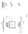
- FIG. 1shows the RFID reader communicating with RFID transponders and other transmitters.
- FIG. 2Ashows three ways in which the RFID reader and gateway can communicate with each other.
- FIG. 2Bshows an example network architecture if the RFID readers and gateways use power line carrier communications.
- FIG. 2Cshows an example network architecture if the RFID readers and gateways use active RF communications.
- FIG. 3shows a generalized network architecture of the security network.
- FIG. 4shows the distributed manner in which the present invention would be installed into an example house.
- FIG. 5Ashows a generalized architecture of a device in the security system containing a control function.
- FIG. 5Bshows the control functions in multiple devices logically connecting to each other.
- FIG. 6shows multiple ways in which a gateway can be configured to reach different private and external networks.
- FIG. 7shows some of the multiple ways in which a gateway can be configured to reach emergency response agencies and other terminals.
- FIG. 8shows an example layout of a house with multiple RFID readers, and the manner in which the RFID readers may form a network to use wireless communications to reach a gateway.
- FIG. 9shows an architecture of the RF reader.
- FIG. 10shows an architecture of the gateway.
- FIG. 11shows an architecture of the RF transponder.
- FIG. 12shows an architecture of the RF transponder with an amplifier.
- FIG. 13is a flow chart for a method of providing a remote monitoring function.
- FIG. 14shows the manner in which an RFID reader can be connected to a controller that is designed to interface with a conventional alarm panel.
- FIG. 15shows the manner in which an RFID reader can be connected to a controller that is part of a conventional alarm panel.
- FIG. 16shows an example configuration in which power line carrier communication is used.
- FIG. 17shows an example embodiment of an RF reader without an acoustic transducer, and in approximate proportion to a standard power outlet.
- FIG. 18shows an example embodiment of an RF reader with an acoustic transducer.
- FIGS. 19A and 19Bshow one way in which the controller or RFID reader may be mounted to a plate, and then mounted to an outlet.
- FIGS. 20A and 20Bshow the locations on the RFID reader where patch or microstrip antennas may be mounted so as to provide directivity to the transmissions.
- FIG. 21shows an example embodiment of a keypad and display.
- FIG. 22shows one way in which the keypad may be mounted onto an electrical box while permitting a light switch to protrude.
- FIG. 23Ashows an example embodiment of a passive infrared sensor integrated into a light switch.
- FIG. 23Bshows an example embodiment of a gateway.
- FIGS. 24A and 24Bshow alternate forms of a passive infrared sensor that may be used with the security system.
- FIGS. 25A and 25Bshow examples of LED generators and LED detectors that may be used as intrusion sensors.
- FIG. 26shows examples of corner antennas for RFID transponders and examples of window frames in which they may be mounted.
- the present inventionis a highly reliable system and method for constructing a security system, or security network, for use in a building, such as a commercial building, single or multifamily residence, or apartment.
- a buildingsuch as a commercial building, single or multifamily residence, or apartment.
- security systemshall be used throughout, though in the context of this present application, the terms “security system” and “security network” shall be considered interchangeable as they apply to the present invention.
- the security systemmay also be used for buildings that are smaller structures such as sheds, boathouses, other storage facilities, and the like. Throughout this specification, a residential house will be used as an example when describing aspects of the present invention. However, the present invention is equally application to other types of buildings.
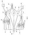
- FIG. 1shows a very basic configuration of the security system with a single RFID reader 200 communicating with several RFID transponders 100 , one of which has an associated intrusion sensor 600 , one of which has any one of several other sensors 620 , an a third which has no sensor.
- the controller function 250is not shown in the diagram, but is present in the RFID reader 200 .
- a security system with a single RFID reader 200can be expanded to support multiple RFID readers 200 .
- the systemcan communicate with external networks 410 using a device known as a gateway 300 .
- FIGS. 2A , 2 B, and 2 Cshow the way in which multiple RFID readers 200 and gateways 300 communicate with each other in the security system.
- FIG. 2Ashows three available connections: via active RF communications 422 , via power line carrier communications 202 over the power lines 430 , or via hardwire connection 431 .
- FIG. 2Bshows communications via power line carrier communications 202 , where any of the devices can directly connect to any of the other devices.
- FIG. 2Cshows a network in which active RF communications 422 is used; some of the devices can directly communicate with each other and some pairs of devices can only communicate through one or more intermediate devices.
- FIG. 8shows an example of how the logical architecture of FIG. 2C might appear in a sample residence.
- FIG. 3shows various examples of the types of devices that can be contained and can communicate within a security system.
- different example gateways 300 , 510 , and 520show how the devices in the security system can also communicate to networks and devices external to the security system.
- other devices 550 and functionscan be added and integrated.
- other device 550means generically any powered device generally following the architecture shown in FIG. 5A , and includes RFID readers 200 , gateways 300 , email devices 530 , siren devices 530 , camera/audio devices 540 , as well as devices not specifically identified here but designed to operate in the inventive security system by connecting to the security network 400 and being capable of communicating over the security network 400 with example devices shown in FIG. 5A .
- a keypad 500may be added to provide a method for user interface.
- a gateway 300can be provided to enable communications between the security system and external networks 410 such as, for example, a security monitoring company. The gateway 300 may also convert protocols between the security system and a WiFi network 401 or a USB port of a computer 450 .
- a siren 551may be added to provide loud noise-making capability.
- An email terminal 530can be added to initiate and receive messages to/from external networks 410 and via a gateway 300 .
- Other sensors 620may be added to detect fire, smoke, heat, water, temperature, vibration, motion, as well as other measurable events or items.
- a camera and/or audio terminal 540may be added to enable remote monitoring via a gateway 300 .
- a keyfob 561may be added to enable wireless function control of the security system. This list of devices that can be added is not intended to be exhaustive, and other types can also be created and added as well.
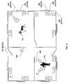
- the distributed nature of the security systemis shown in the example layout in FIG. 4 for a small house.
- an intrusion sensor 600 and RFID transponder 100are mounted at each opening in the house, such as windows 702 and doors 701 , for which monitoring is desired.
- an intrusion sensor 600 and RFID transponder 100are mounted at each opening in the house.
- an intrusion sensor 600 and RFID transponder 100are mounted at each opening in the house.
- one or more RFID readers 200are mounted at each opening in the house, such as windows 702 and doors 701 , for which monitoring is desired.
- an intrusion sensor 600 and RFID transponder 100are mounted at each opening in the house, such as windows 702 and doors 701 , for which monitoring is desired.
- RFID readers 200are mounted at each opening in the house, such as windows 702 and doors 701 , for which monitoring is desired.
- RFID readers 200are mounted at each opening in the house, such as windows 702 and doors 701 , for which monitoring is desired.
- RFID readers 200are mounted at each opening in the house
- each RFID reader 200is responsible for the RFID transponders 100 in a predetermined read range of each RFID reader 200 .
- the range of wireless communicationsis dependent, in part, upon many environmental factors in addition to the specific design parameters of the RFID readers 200 and RFID transponders 100 .
- the median size of one-family houseshas ranged from 1,900 to 2,100 square feet (176 to 195 square meters) in the last ten years, with approximately two-thirds under 2,400 square feet (223 square meters). This implies typical rooms in the house of 13 to 20 square meters, with typical wall lengths in each room ranging from 3 to 6 meters. It is likely in many residential homes that most installed RFID readers 200 will be able to communicate with RFID transponders 100 in multiple rooms. Therefore, in many cases with this system it will be possible to either install fewer RFID readers 200 than major rooms in a building, or to follow the guideline of one RFID reader 200 per major room, creating a system with excellent spatial antenna diversity as well as redundancy in the event of single component failure.
- the RFID reader 200can be installed in various locations within a house or building. The choice of location is at the convenience of the installer or building occupant, and is typically chosen to provide good wireless propagation ability. In a residential house example, the RFID reader 200 can be installed in a room, a hallway, in the attic above a room, or in the basement/crawl space below a room. When installed in a room or a hallway, the RFID reader 200 may either be (i) mounted on a wall/ceiling and obtain its power remotely in a manner similar to conventional motion detectors, or (ii) mounted on or near an outlet and obtain its power locally from the aforesaid outlet. The choice of installation location will determine the physical shape and embodiment of the RFID reader 200 , but the primary function will remain the same.
- the RFID reader 200is the central element in the security system, and it typically is capable of several basic and optional forms of communication.
- the first basic formis the backscatter modulation 420 technique, used to communicate with the RFID transponders 100 .
- the second basic formis active RF communication 422 , used to communicate with other powered devices within the security system such as other RFID readers 200 , gateways, etc.
- both formsare wireless communications, but active RF communication 422 is differentiated from backscatter modulation 420 in that (i) backscatter modulation 420 relies on an RFID reader 200 to initiate a wireless communication and an RFID transponder 100 can only respond with a wireless communication 421 that is based upon or derived from the wireless transmission originated by the RFID reader 200 , and (ii) active RF communication is that which independently originated from any powered device in the security system using its own generated carrier frequency independent of any other device.
- a first optional form of communicationis power line carrier communication 202 that travels over standard power lines 430 .
- a second optional form of communicationis a hardwired connection 431 .
- a second common elementis the controller function 250 .
- Conventional alarm panelstypically contain a single controller, and all other contacts, motion detectors, etc. are fairly dumb from an electronics and software perspective. For this reason, the alarm panel must be hidden in the house because, if the alarm panel were discovered and disabled, all of the intelligence of the system would be lost.
- the controller function 250 of the present inventionis distributed through most, if not all, of the powered devices in the security system.
- the controller function 250is a set of software logic that can reside in the processor and memory of a number of different devices within the security system, including within the RFID reader 200 .
- FIG. 5Ashows a generalized architecture for any device used in the security system. Elements common to most devices will be power 264 , a processor 261 , memory 266 associated with the processor, and the chosen networking 262 . If the memory 266 is of an appropriate type and size, the memory 266 can contain a controller function 250 , consisting of both program code 251 and configuration data 252 . The program code 251 will generally contain both controller function 250 code common to all devices as well as code specific to the device type. For example, an RFID reader 200 will have certain device-specific hardware 263 that requires matching code, and a gateway 300 may have different device-specific hardware 263 that requires different matching code.
- each control function 250 in each devicecan communicate with all other control functions 250 in all other devices as shown in FIG. 5B .
- the purpose of replicating the controller function 250 on multiple devicesis to provide a high level of redundancy throughout the entire security system, and to reduce or eliminate possible points of failure (whether component failure, power failure, or disablement by an intruder).
- the controller functions 250 implemented on each deviceperform substantially the same common functions; therefore, the chances of system disablement by an intruder are fairly low.
- the controller functions 250arbitrate among themselves to determine which controller function 250 shall be the master controller for a given period of time.
- the preferred arbitration schemeconsists of a periodic self-check test by each controller function 250 , and the present master controller may remain the master controller as long as its own periodic self-check is okay and reported to the other controller functions 250 in the security system. If the present master controller fails its self-check test, or has simply failed for any reason or been disabled, and there is at least one other controller function 250 whose self-check is okay, the failing master controller will abdicate and the other controller function 250 whose self-check is okay will assume the master controller role.
- the controller functions 250may elect a master controller from among themselves by each choosing a random number from a random number generator, and then selecting the controller function 250 with the lowest random number.
- arbitration schemesthat are widely known, and any number are equally useful without deducting from the inventiveness of permitting multiple controller functions 250 in a single security system, as long as the result is that in a multi-controller function 250 system, no more than one controller function 250 is the master controller at any one time.
- one controller function 250is master controller and the remaining controller functions 250 are slave controllers, keeping a copy of all parameters, configurations, tables, and status but not duplicating the actions of the master controller.
- the security systemcan receive updated program code 251 and selectively update the control function 250 in just one of the devices. If the single device updates its program code 251 and operates successfully, then the program code 251 can be updated in other devices. If the first device cannot successfully update its program code 251 and operate, then the first device can revert to a copy of older program code 251 still stored in other devices. Because of the distributed nature of the control functions 250 , the security system of the present invention does not suffer the risks of conventional alarm panels which had only one controller.
- the controller function 250typically performs the following major logic activities, although the following list is not meant to be limiting:
- the inventive security systempermits monitoring as well as access to various external networks 410 through a gateway device 300 .
- Each gateway 300is configured with appropriate hardware and software that match the external network 410 to which access is desired.
- examples of external networks 410 to which access can be providedare private Ethernets 401 , CMRS 402 , PSTN 403 , WiFi 404 , and the Internet 405 .
- This list of external networks 400is not meant to be limiting, and appropriate hardware and software can be provided to enable the gateway 300 to access other network formats and protocols as well.
- Private Ethernets 401are those which might exist only within a building or residence, servicing local computer terminals 450 . If the gateway 300 is connected to a private Ethernet 401 , access to the Internet 405 can then be provided through a cable modem 440 , DSL 441 , or other type of broadband network 442 . There are too many suppliers to enumerate here.
- a block diagram of the gateway 300is shown in FIG. 10 ; it can be seen that the specific architecture of the gateway 300 follows the generic device architecture previously shown in FIG. 5A .
- the major logic functions, including a controller function 250are implemented in the firmware or software executed by the microprocessor 303 of the gateway 300 .
- the microprocessor 303contains non-volatile memory 304 for storing the controller function 250 firmware or software as well as the configuration of the system.
- the gateway 300typically has its own power supply 308 and can also contain a backup battery 309 , if desired, for use in case of loss of normal power.
- the gateway 300will typically store the controller function 250 configuration information in the form of one or more tables in non-volatile memory 304 .
- the table entriesenable the gateway 300 to store the identity of each RFID reader 200 and other devices, along with the capabilities of each RFID reader 200 and other devices, the identity of each RFID transponder 100 , along with the type of RFID transponder 100 and any associated intrusion sensors 600 , and the association of various sensors in the system. For example, as discussed later, it is advantageous for the controller function 250 to associate particular passive infrared sensors 570 with particular RFID readers 200 containing a microwave Doppler motion function. With respect to each RFID transponder 100 , the table entries may further contain radio frequency, power level, and modulation technique data.
- table entriescan enable the controller function 250 to command an RFID reader 200 to use a particular combination of radio frequency, modulation technique, antenna, and power level for a particular RFID transponder 100 , wherein the combination used can vary when communicating with each separate RFID reader 200 , RFID transponder 100 , or other device 551 .
- the tablesmay contain state information, such as the reported status of any battery 111 included with an RFID transponder 100 .
- One embodiment of the gateway 300can take the form shown in FIG. 23B .
- the security systempermits the installation of multiple gateways 300 in a single security network 400 , each of which can interface to the same or different external networks 410 .
- a second gateway 300can serve to function as an alternate or backup gateway 300 for cases in which the first gateway 300 fails, such as component failure, disablement or destruction by an intruder, or loss of power at the outlet where the first gateway 300 is plugged in.
- the gateway 300will typically communicate with the RFID readers 200 using any of active RF communications 422 through an RF interface 305 , analog interface 306 , and antenna 307 , a power line carrier protocol 202 , or hardwire interface 209 . There are tradeoffs to consider with each form of communication. Active RF communications 422 will require that the gateway 300 be within RF propagation range of other devices, such as RFID readers 200 . In a typical 2,100 square foot house, this will generally not be a problem, especially given the allowed power limits (as discussed below).
- Power line carrier protocols 202can extend the range of communications, but are susceptible to interference on the power line 430 and interruption if the breaker for that power circuit “trips.”
- Hardwire communications 209is the most reliable because it is dedicated; however, it entails the cost of installing dedicated wires 431 .
- Power line carrier 202 protocolsallow the sending of data between devices using the existing power lines 430 in a building.
- One of the first protocols for doing thisis known as the X-10 protocol.
- CEBusConsumer Electronics Bus
- EIA600EIA600
- the primary driver for deciding upon a particular power line carrier protocolis the availability of chipsets, reference designs, and related components at high manufacturing volumes and at low manufacturing cost. Furthermore, compatibility with other products in the home automation field would be an additional advantage.
- power line carrier communications 202were desired by a homeowner or building owner, the preferred choice would be the standard HomePlug, embodied in the Intellon chipset.
- HomePlugoffers sufficient data speeds over standard power lines 430 at a reported distance of up to 300 meters. That standard operates using frequencies between 4.3 and 20.9 MHz, and includes security and encryption protocols to prevent eavesdropping over the power lines 430 from adjacent houses or buildings.
- the specific choice of which protocol to useis at the designer's discretion, and does not subtract from the inventiveness of this system.
- a form of the gateway 300may also be configured to use hardwired connections 431 through a hardwire interface 209 to one or more RFID readers 200 .
- Homeowners and building ownersgenerally desire one or two types of alerts in the event that an intrusion is detected.
- an audible alertmay be desired whereby a loud siren 551 is activated both to frighten the intruder and to call attention to the building so that any passers-by may take notice of the intruder or any evidence of the intrusion.
- the building ownerprefers the so-called silent alert whereby no audible alert is made so as to lull the intruder into believing he has not been discovered and therefore may still be there when law enforcement personnel arrive.
- the second type of alertinvolves messaging an emergency response agency 460 , indicating the detection of an intrusion and the identity of the building, as shown in FIG. 7 .
- the emergency response agency 460may be public or private, depending upon the local customs, and so, for example, may be an alarm services company or the city police department.
- the gateway 300 of the inventive systemsupports the second type of foregoing alert by including a slot capable of receiving optional modules 310 , 311 , 312 , or 313 which provide, respectively, a modem module 310 , wireless module 311 , WiFi module 312 , or Ethernet module 313 .
- modules 310 to 313are preferably in the form of an industry standard PCMCIA or compact flash (CF) module 330 , thereby allowing the selection of any of a growing variety of modules made by various vendors manufactured to these standards.
- the modem module 310is used for connection to a public switched telephone network (PSTN) 403 ; the wireless module 311 is used for connection to a commercial mobile radio service (CMRS) network 402 such as any of the widely available CDMA, TDMA, or GSM-based 2G, 2.5 G, or 3G wireless networks.
- CMRScommercial mobile radio service
- the WiFi module 312is used for connection to private or public WiFi networks 404 ; the Ethernet module 313 is use for connection to private or public Ethernets 401 .
- Certain building ownerswill prefer the high security level offered by sending an alert message through a CMRS 402 network or WiFi network 404 .
- the use of a CMRS network 402 or WiFi network 404 by the gateway 300overcomes a potential point of failure that occurs if the intruder were to cut the telephone wires prior to attempting an intrusion. If the building owner has installed at least two gateways 300 in the system, one gateway 300 may have a wireless module 311 installed and a second may have a modem module 310 installed. This provides the inventive security system with two separate communication paths for sending alerts to the emergency response agency 460 as shown in FIG. 7 . By placing different gateways 300 in very different location in the building, the building owner significantly decreases the likelihood that an intruder can discover and defeat the security system.
- the controller function 250in particular when contained in a gateway 300 with a wireless module 311 or WiFi module 312 , offers an even higher level of security that is particularly attractive to marketing the inventive security system to apartment dwellers.
- security systems of any typehave not been sold and installed into apartments for several reasons.
- Apartment dwellersare more transient than homeowners, making it difficult for the dweller or an alarm services company to recoup an investment in installing a system.
- Of larger issue, though,is the small size of apartments relative to houses. The smaller size makes it difficult to effectively hide the alarm panel of conventional security systems, making it vulnerable to discovery and then disconnection or destruction during the pre-alert period.
- the pre-alert period of any security systemis the time allowed by the alarm panel for the normal homeowner to enter the home and disarm the system by entering an appropriate code or password into a keypad.
- This pre-alert timeis often set to 30 seconds to allow for the fumbling of keys, the carrying of groceries, the removal of gloves, etc.
- 30 secondsis a relatively long time in which an intruder can search the apartment seeking the alarm panel and then preventing alert. Therefore, security systems have not been considered a viable option for most apartments. Yet, at least 35% of the households in the U.S. live in apartments and their security needs are not less important than those of homeowners.
- the inventive security systemincludes an additional remote monitoring function in the controller function 250 , which can be selectively enabled at the discretion of the system user, typically for use with the wireless module 311 or WiFi module 312 , but also available for use with the Ethernet module 313 .
- SMSShort Messaging Service
- Most CMRS 402 networks based upon CDMA, TDMA, or GSMhave supported a feature known as two-way Short Messaging Service (SMS). Available under many brand names, SMS is a connectionless service that enables the sending of short text messages between a combination of wireless and/or wired entities.
- Public WiFi networks 404 and Ethernet networkshave a similar messaging capability.
- the controller function 250includes a capability whereby the controller function 250 can send a message, via the wireless module 311 or WiFi module 312 and using the SMS feature of CMRS 402 networks or messaging feature of WiFi networks 404 , to a designated remote processor at an alarm services company, or other designated location, at the time that a pre-alert period begins and again at the time that the security system has been disabled by the normal user, such as the apartment dweller, by entering the normal disarm code.
- the controller function 250can send a different message, via the wireless module 311 or WiFi module 312 and using the SMS feature of CMRS networks 402 or messaging feature of WiFi networks 404 , to the same designated processor if the normal user enters an abnormal disarm code that signals distress, such as when, for example, an intruder has forced entry by following the apartment dweller home and using a weapon to force the apartment dweller to enter her apartment with the intruder and disarm the security system.
- an abnormal disarm codethat signals distress
- the remote monitoring functionoperates as shown in FIG. 13 and described in more detail below, assuming that the function has been enabled by the user:
- An intrusionis detected in the building, such as the apartment,
- this inventive remote monitoring functionnow enables the installation of this inventive security system into apartments without the historical risk that the system can be rendered useless by the discovery and disablement or destruction by the intruder.
- this functionenabled, even if the intruder were to disable or destroy the system, a remote alert could still be signaled because a message indicating a transition to disarm state would not be sent, and a timer would automatically conclude remotely at the designated processor.
- This functionis obviously not limited to just apartments and could be used for any building.
- a gateway 300can also be configured to send either an SMS-based message through the CMRS 402 or an email message through a WiFi network 404 or Ethernet network 401 to the Internet 405 and to any email address based upon selected user events. For example, an individual away from home during the day may want a message sent to his pager, wireless phone, or office email on computer 450 if the inventive security system is disarmed at any point during the day when no one is supposed to be at home. Alternately, a parent may want a message sent when a child has retuned home from school and disarmed the security system.
- a homeownerhas provided a temporary disarm code to a service company scheduled to work in the home, and the homeowner wants to receive a message when the work personnel have arrived and entered the home.
- the owner of the security systemcan discriminate among the persons authorized to disarm the system. Any message sent, as described herein, can contain an indication identifying the code and/or the person that entered the disarm code.
- the disarm codeitself is not sent for the obvious security reasons, just an identifier associated with the code.
- the gateway 300can send or receive updated software, parameters, configuration, or remote commands, as well as distribute these updated software, parameters, configuration, or remote commands to other controller functions 250 embedded in other devices such as RFID readers 200 .
- a copy of the configurationincluding all of the table entries, can be sent to a remote processor for both backup and as an aid to responding to any reported emergency. If, for any reason, all of the controller functions 250 within the security system ever experienced a catastrophic failure whereby its configuration were ever lost, the copy of the configuration stored at the remote processor could be downloaded to a restarted or replacement controller function 250 .
- Certain parameterscan be downloaded to the controller function 250 and then propagated, in this example, to the appropriate glass breakage detection functions that may be contained within the system. Therefore, for example, if a homeowner were experiencing an unusual number of false alarm indications from a glass breakage detection function, remote technical personnel could remotely make adjustments in certain parameters and then download these new parameters to the controller function 250 .
- the controller function 250can also report periodic status and/or operating problems detected by the system to the emergency response agency 460 or to the manufacturer of the system.
- One example of the usefulness of this functionis that reports of usage statistics, status, and/or problems can be generated by an emergency response agency 460 and a copy can be provided to the customer as part of his monthly bill. Furthermore, the usage statistics of similarly situated customers can be compared and analyzed for any useful patterns.
- the RFID reader 200is typically designed to be inexpensively manufactured since, in each installed security system, there may be approximately one RFID reader 200 for each major room to be monitored. From a physical form factor perspective, the RFID reader 200 of the present invention can be made in several embodiments, where the form of the embodiment is partially dependent upon whether the RFID reader 200 is being used with existing security systems or whether the RFID reader 200 is being used in a new self-install system. Embodiments particularly useful in self-installed security systems, wherein the RFID reader 200 , or other devices 550 such as for example gateways 300 , obtains its power from a nearby standard AC power outlet 720 shall hereinafter be termed “self-install embodiments.” In this embodiment, shown in FIG.
- the packaging of the RFID reader 200 , or other devices 550such as for example gateways 300 , may have the plug integrated into the package such that the RFID reader 200 or other device 550 is plugged into a standard outlet 720 without any associated extension cords, power strips, or the like.
- FIGS. 14 and 15show the RFID reader 200 as it can be connected, typically via hardwire, to controllers associated with conventional alarm panels.
- Existing embodiments of the RFID reader 200will generally not include a controller function 250 . Rather, the controller function 250 may be implemented using a dedicated processor on a panel interface module 350 as shown in FIG. 14 or it may be incorporated into the processor of a controller 351 associated with the alarm panel of conventional security systems. In existing embodiments, the panel interface module 350 and associated RFID readers 200 derive their power from the power supply and/or lead acid battery of the conventional alarm panel.
- the self-install embodiment of the RFID reader 200is provided with threaded screw holes on the rear of the packaging, as shown in FIG. 19A .
- holescan be drilled into a plate 722 , which may be an existing outlet cover (for example, if the user has stylized outlet covers that he wishes to preserve) whereby the holes are of the size and location that match the holes on the rear of the packaging for the RFID reader 200 or the gateway 300 , for example.
- the usercan employ a plate in the shape of an extended outlet cover 721 shown in FIG. 19B which provides additional mechanical support through the use of additional screw attachment points.
- the plate 722 or 721can be first attached to the rear of the RFID reader 200 or other device packaging, using the screws 724 shown, and if necessary, spacers or washers.
- the RFID reader 200 or other example devices 550can be plugged into the outlet 720 , whereby the plate 722 or 721 is in alignment with the sockets of the outlet 720 .
- an attachment screw 723can be used to attach the plate 722 or 721 to the socket assembly of the outlet 720 .
- FIG. 9shows a block diagram the RFID reader 200 .
- Blocks shown in solid linesare typically included in each embodiment of an RFID reader 200 .
- Blocks shown in dashed linesmay or may not be included in a particular embodiment, depending upon the integration wishes of the designer.
- the RFID reader 200will include at a minimum a microprocessor 203 controlling transmission and receive functions through an RF interface 204 chipset, an analog interface 205 , and antenna 206 .
- the microprocessor 203 , RF interface 204 , and analog interface 205may be incorporated as a single chipset or discretely separated.
- FIG. 9shows only a single antenna 206 for simplicity, as will be discussed later it may be advantageous for the RFID reader 200 to contain more than one antenna 206 to provide increased directivity.
- the analog circuits 205will typically enable the switching of the RF interface 204 between the multiple antenna elements 206 .
- this existing embodiment of the RFID reader 200may only support limited functions such as only backscatter modulation if the RFID reader 200 will only be in wireless communications with RFID transponders 100 and not with any other devices 550 .
- the processor 203 and memory 204may not be present if the controller functions 250 are incorporated into the panel interface module 350 or controller 351 of a conventional alarm panel.
- the existing embodiment of the RFID reader 200may not have a power supply 207 since power can be derived directly or indirectly from the conventional alarm panel.
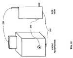
- the configuration of the RFID reader 200includes only a single antenna, it can take the form shown in FIG. 17 with one PC motherboard containing most of the components, with a slot for accepting a daughter card in the form factor of an industry standard PCMCIA or compact flash (CF) module 220 .
- PCMCIA or compact flash (CF) module 220These module sizes are preferred because the growing variety of modules made by various vendors and manufactured to these standards are leading to rapidly declining component and manufacturing costs for chipsets, discrete resistors, capacitors, inductors, antennas, packaging, and the like. Furthermore, it may ease the process of FCC equipment certification to make the intentional radiating portions of the RFID reader 200 into a mechanical package separate from the remaining circuits. It is not a requirement of this present invention that the RFID reader 200 be constructed in these two parts as shown in FIG.
- RFID reader 200can also be produced with all components integrated into a single package, perhaps even smaller in size, without detracting from the present inventive architecture and combination of functions, circuits, and logic. For example, as will be discussed later, when multiple antennas 206 are used the packaging is generally integrated.
- the RFID reader 200includes a local power supply 207 . If battery backup is desired, the packaging of the RFID reader 200 also permits the installation of a battery 208 for backup purposes in case normal power supply 207 is interrupted.
- the RFID reader 200will generally also include a controller function 250 , therefore the microprocessor 203 will also require sufficient memory 211 for program and data storage.
- the lowest cost form of the self-install embodimentwill use active RF communications 422 between multiple RFID readers 200 and other devices 550 .
- the RFID reader 200may also include a power line interface 202 or a hardwire interface 209 to provide communications capability over wires, as discussed elsewhere.
- the RFID reader 200will typically communicate with the RFID transponders 100 using frequencies in one or more of following unlicensed frequency bands: 902 to 928 MHz, 2435 to 2465 MHz, 2400 to 2483 MHz, or 5725 to 5850 MHz. These bands permit the use of unlicensed secondary transmitters, and are part of the bands that have become popular for the development of cordless phones and wireless LAN networks, thereby leading to the wide availability of many low cost components that are required for this invention, such as the RF interface 204 chips, analog interface 205 components, and antennas 206 . There are 3 different FCC rule sets applicable to the present invention, which will be discussed briefly.
- Each phone manufactureruses its own modulation and protocol format.
- For data devicesthere are several well known standards that use the 2400 to 2483 band, such as 802.11, 802.11b (WiFi), Bluetooth, ZigBee (HomeRF-lite), and IEEE 802.15.4, among others.
- the present inventionhas a substantial advantage over the aforementioned products in that the RFID readers 200 , gateways 300 , and other devices 550 of the security system are fixed.
- Other productssuch as cordless phones and various data devices usually have at least one handheld, usually battery powered, component.
- the FCC's Maximum Permitted Exposure (MPE) guidelinesdescribed in OET 65 , generally cause manufacturers to limit transmission power of handheld devices to 100 mW or less. Since most wireless links are symmetrical, once the handheld device (such as the cordless phone) is power limited, any fixed unit (such as the cordless base unit) is also limited in power to match the handheld device. Given that the RFID reader 200 , gateway 300 , and other devices 550 of the security system are not handheld, they can use the full power permitted by the FCC rules and still meet the MPE guidelines.
- the preferred mechanism of communications by and between RFID readers 200 , gateways 300 , and other devicesis active RF communications 422 .
- the inventionis not limiting, and modulation formats and protocols using either FHSS or DM can be employed.
- the active RF communications 422can use Gaussian Frequency Shift Keyed (GFSK) modulation with FHSS. This particular modulation format has already been used quite successfully and inexpensively for Bluetooth, 802.11, and other data systems to achieve raw data rates on the order of 1 Mbps.
- GFSKGaussian Frequency Shift Keyed
- the active RF communications 422 used in the security systemshould achieve higher reliability and range, and lower susceptibility to interference than other collocated products.
- RFID readers 200 , gateways 300 , and other devices 550When using active RF communications 422 , RFID readers 200 , gateways 300 , and other devices 550 function as a network of devices. A message originating on one device may pass through intermediate devices before terminating on the destination devices, as shown in FIGS. 2C and 8 .
- the RFID readers 200 , gateways 300 , and other devices 550determine their own network topology based upon the ability of each device to reliably receive the transmissions from other devices. As will be discussed later, the antennas 206 used in these devices may be directional, and therefore it is not always certain that each device can directly transmit to and receive from every other device.
- each devicecan communicate with at least one other device, and that the devices can then form for themselves a network that enables the routing of a message from any one device to any other device.
- Networking protocolsare well understood in the art and therefore not covered here.
- the devices described hereintypically will use the unique originating and destination address of each device in the header of each message sent in routing messages within the network.
- the RFID readers 200can use both 47 CFR 15.245 and 47 CFR 15.247 rules for their wireless communications 420 with the RFID transponders 100 .
- the RFID readers 200can communicate to the RFID transponders 100 using one protocol, at a maximum power of 4 W for any length of time, and then switch to a second protocol, if desired, at a maximum power of 7.5 W to obtain a response 421 from an RFID transponder 100 .
- the RFID reader 200can transmit at 7.5 W for only 1 ms under the 47 CFR 15.245, that time period is more than enough to obtain tens or hundreds of bits of data from an RFID transponder 100 .
- the extra permitted 2.7 dB of power under 47 CFR 15.245is useful for increasing the read range of the RFID reader 200 .
- the RFID reader 200can use the longer transmission times at 4 W to deliver power to the RFID transponders 100 , as described elsewhere, and reserve the brief bursts at 7.5 W only for data transfer.
- the RFID readers 200 , gateways 300 , and other devices 550can use a power line carrier protocol 202 , matching of course, the chipsets and protocols discussed for the gateway 300 .
- Either communications mechanismpermits the homeowner or building owner to install the RFID readers 200 by simply plugging each into an outlet 720 in approximately each major room.
- the power line carrier protocol 202is connected to the outlet 720 via an AC connector 201 .
- the RFID readers 200 , gateways 300 , and other devices 550can then use the method disclosed later to associate themselves with each other and begin communications without the need to install any new wires.
- Each RFID reader 200communicates with one or more RFID transponders 100 typically using modulated backscatter techniques.
- modulated backscatter techniquesare very well understood by those skilled in the art, and have been well discussed in a plethora of literature including patent specifications, trade publications, marketing materials, and the like.
- the readeris directed to RFID Handbook Radio-Frequency Identification: Fundamentals And Applications, by Klaus Finkenzeller, published by John Wiley, 1999.
- U.S. Pat. No. 6,147,605, issued to Vega et al.provides additional material on the design and theory of modulated backscatter techniques.
- Patent application Ser. No. 10/072,984, filed by Shanks et al.also provides material on the design and theory of modulated backscatter techniques.
- Some centralized transceiversattempt to use diversity antennas to improve their reliability; however, these antennas are separated only by the width of the packaging, which is frequently much less than one wavelength of the chosen frequency (i.e., 87 cm at 345 MHz and 69 cm at 433 MHz).
- spatial diversity of antennasworks best when the antennas are separated by more than one wavelength at the chosen frequency.
- RFID readers 200are separated into multiple rooms, creating excellent spatial diversity and the ability to overcome environmental effects such as multipath and signal blockage. Multipath and signal blockage are effects of the RF path between any transmitter and receiver.
- Most cellular systemsuse diversity antennas separated by multiple wavelengths to help overcome the effects of multipath and signal blockage.
- each RFID reader 200in most installations there will be multiple RFID readers 200 in a building. There will therefore be an independent RF path between each RFID reader 200 and each RFID transponder 100 .
- the master controllersequences transmissions from the RFID readers 200 so that only one RFID reader 200 is transmitting at a time. Besides reducing the potential for interference, this allows the other RFID readers 200 to listen to both the transmitting RFID reader 200 and the subsequent response from the RFID transponders 100 . If the RF path between the transmitting RFID reader 200 and the RFID transponder 100 is subject to some form of multipath or signal blockage, it is possible and even highly probable that one of the remaining RFID readers 200 is capable of detecting and interpreting the signal. If the transmitting RFID reader 200 is having trouble receiving an adequate response from a particular RFID transponder 100 , the master controller will then poll the remaining RFID readers 200 to determine whether the response was received by any of them.
- RFID readers 200 for other applicationsmust include the complexity to deal with many simultaneous tags in the read zone, tags moving rapidly, or tags only briefly in the read zone, the present invention can take advantage of the controlled static relationship in the following ways.
- the RFID reader 200can poll each RFID transponder 100 individually, preventing collisions or interference.
- the RFID reader 200can use longer integration times in its signal processing to increase the reliability of the read signal, permitting successful reading at longer distances and lower power when compared with RFID applications with mobile tags.
- the RFID reader 200can make changes in specific frequency while remaining within the specified unlicensed frequency band, in an attempt to find, for each RFID transponder 100 , an optimal center frequency, given the manufacturing tolerances of the components in each RFID transponder 100 and any environment effects that may be creating more absorption or reflection at a particular frequency.
- the controller function 250can sequence the RFID readers 200 in time so that the RFID readers 200 do not interfere with each other.
- the controller function 250can use the excellent spatial diversity created by the distributed nature of the RFID readers 200 to increase and improve the reliability of each read. That is, one RFID reader 200 can initiate the transmission sequence 420 , but multiple RFID readers 200 can tune and read the response 421 from the RFID transponder 100 . Thus, the multiple RFID readers 200 can operate as a network of receivers to demodulate and interpret the response 421 from the RFID transponder 100 .
- the RFID transponders 100are typically static, and because the events (such as intrusion) that affect the status of the sensors connected to the RFID transponders 100 are relatively slow compared to the speed of electronics in the RFID readers 200 , the RFID readers 200 have the opportunity to pick and choose moments of low quiescent interference from other products in which to perform their reads with maximum signal-to-noise ratio potential—all without missing the events themselves.
- the RFID reader 200can use different power levels when communicating with each RFID transponder 100 .
- Lower path lossesrequire lower power to communicate; conversely, the RFID reader 200 can step up the power, within the specified limits of the FCC rules, to compensate for higher path losses.
- the RFID reader 200can determine the lowest power level to use for each RFID transponder 100 by sequentially stepping down its transmit power 420 on successive reads until no return signal 421 can be detected. Then the power level can be increased one or two incremental levels. This determined level can then be used for successive reads. This use of the lowest necessary power level for each RFID transponder 100 can help reduce the possibility of interference while ensuring that each RFID transponder 100 can always be read.
- the master controller and RFID readers 200can determine and store the typical characteristics of transmission between each RFID transponder 100 and each RFID reader 200 (such as signal power, signal-to-noise ratio, turn on time, modulation bit time, etc.), and determine from any change in the characteristics of transmission whether a potential problem exists.
- the RFID reader 200can immediately detect attempts to tamper with the RFID transponder 100 , such as partial or full shielding, deformation, destruction, or removal.
- the RFID reader 200 of the present inventionhas a demonstrated wireless range of up to 30 meters when communicating with the RFID transponders 100 , depending upon the building construction materials, placement of the RFID reader 200 in the room, and the furniture and other materials in the room which may have certain reflective or absorptive properties. This range is more than sufficient for the majority of homes and other buildings in the target market of the present security system, whereby the system can be implemented in a ratio of approximately one RFID reader 200 per major room (i.e., a hallway or foyer is not considered a major room for the purposes of the present discussion, but a living room or bedroom is a major room).
- the RFID reader 200is available with several options that increase both the level of security and functionality in the inventive security system.
- One optionenhances the RFID reader 200 to include an acoustic transducer 210 capable of both receiving and emitting sound waves that enables a glass breakage detection capability in the RFID reader 200 .
- Glass breakage sensorshave been widely available for years for both wired and wireless prior art security systems. However, they are available only as standalone sensors selling for $30 to $50 or more.
- the cost of the sensorsgenerally limits their use to just a few rooms in a house or other building. The cost, of course, is due to the need for circuits and processors dedicated to just analyzing the sound waves.
- the only incremental cost of adding the glass breakage detection capabilityis the addition of the acoustic transducer 210 (shown in FIGS. 9 and 18 ). With the addition of this option, glass breakage detection can be available in every room in which an RFID reader 200 has been installed.
- Glass breakage detectionis performed by analyzing received sound waves to look for certain sound patterns distinct in the breaking of glass. These include certain high frequency sounds that occur during the impact and breaking of the glass and low frequencies that occur as a result of the glass flexing from the impact.
- the sound wave analysiscan be performed by any number of widely known signal processing techniques that permit the filtering of received signals and determination of signal peaks at various frequencies over time.
- One advantage of the present invention over conventional standalone glass breakage sensorsis the ability to adjust parameters in the field. Because glass breakage sensors largely rely on the receipt of audio frequencies, they are susceptible to false alarms from anything that generates sounds at the right combination of audio frequencies. Therefore, there is sometimes a requirement that each glass breakage sensor be adjusted after installation to minimize the possibility of false alarms. In some cases, no adjustment is possible because algorithms are permanently stored in firmware at the time of manufacture. Because the glass breakage detection of the present invention is performed by the RFID readers 200 , which include or are in communication with a controller function 250 , the controller function 250 can alter or adjust parameters used by the RFID reader 200 in glass breakage detection. For example, the controller function 250 can contain tables of parameters, each of which applies to different building construction materials or window types.
- the usercan select the appropriate table entry during system configuration, or select another table entry later after experience has been gained with the installed security system.
- a gateway 300has any of the modules 310 to 313 , the controller function 250 can contact an appropriate database via a gateway 300 that is, for example, managed by the manufacturer of the security system to obtain updated parameters.
- the addition of the acoustic transducer 210 , with both sound input and output capability, to the RFID reader 200 for the glass breakage optionalso allows the RFID reader 200 to be used by an emergency response agency 460 as a distributed microphone to listen into the activities of an intruder. Rather than being analyzed, the sound waves can be digitized and sent to the gateway 300 , and then by the gateway 300 to the emergency response agency 460 . After the gateway 300 has sent an alert message to the emergency response agency 460 , any of the installed modules 310 to 313 can be available for use in an audio link.
- the RFID reader 200can contain optional algorithms for the sensing of motion in the room.
- conventional motion sensorsare widely available as standalone devices.
- Conventional motion sensorssuffer from the same disadvantages cited for standalone glass breakage sensors, that is they are standalone devices requiring dedicated processors, circuits, and microwave generators.
- the RFID reader 200already contains all of the hardware components necessary for generating and receiving the radio wave frequencies commonly used in detecting motion; therefore, the RFID reader 200 only requires the addition of algorithms to process the signals for motion in addition to performing its reading of the RFID transponders 100 . Different algorithms are available for motion detection at microwave frequencies.
- Doppler analysisIt is a well-known physical phenomenon that objects moving with respect to a transmitter cause a reflection with a shift in the frequency of the reflected wave. While the shift is not large relative to the carrier frequency, it is easily detectable. Therefore, the RFID reader 200 can perform as a Doppler radar by the rapid sending and receiving of radio pulses, with the subsequent measurement of the reflected pulse relative to the transmitted pulse. People and animals walking at normal speeds will typically generate Doppler shifts of 5 Hz to 100 Hz, depending on the speed and direction of movement relative to the RFID reader 200 antenna 206 .
- the implementation of this algorithm to detect the Doppler shiftcan be, at the discretion of the designer, implemented with a detection circuit or by performing signal analysis using the processor of the RFID reader 200 . In either case, the object of the implementation is to discriminate any change in frequency of the return signal relative to the transmitted signal for the purpose of discerning a Doppler shift.
- the RFID reader 200is capable of altering its transmitted power to vary the detection range of this motion detection function.
- the RFID reader 200in a single integrated package can be capable of (i) communicating with other RFID readers 200 , gateways 300 , and other devices 550 using active RF communications 422 , power line communications 202 , and/or hardwired communications 209 , (ii) communicating with RFID transponders 100 using wireless communications 420 , (iii) detecting motion via Doppler analysis at microwave frequencies, (iv) detecting glass breakage via sound wave analysis of acoustic waves received via an audio transducer 210 , and (v) providing a two-way audio link to an emergency response agency 460 via an audio transducer 210 and via a gateway 300 .
- This RFID reader 200achieves significant cost savings versus conventional security systems through the avoidance of new wire installation and the sharing of communicating and processing circuitry among the multiple functions. Furthermore, because the RFID readers 200 are under the control of a single master controller, the performance of these functions can be coordinated to minimize interference and provide spatial diversity and redundant confirmation of received signals.
- the motion detector implemented in the RFID reader 200is only a single detection technology. Historically, single motion detection technologies, whether microwave, ultrasonic, or passive infrared, all suffer false positive indications. For example, a curtain being blown by a heating vent can occasionally be detected by a Doppler analysis motion detector. Therefore, dual technology motion detectors are sometimes used to increase reliability—for example by combining microwave Doppler with passive infrared so that motion by a warm body is required to trigger an alert.
- An existing embodiment of the RFID reader 200which can be mounted high on a wall or on a ceiling, can incorporate a passive infrared sensor 570 , if desired, to achieve manufacturing cost savings for the same reasons previously discussed for glass breakage.
- the self-install embodiment of the RFID reader 200will typically be mounted directly on power outlets 720 , which are relatively low on the wall in most rooms, incorporating an infrared sensor 570 in the RFID reader 200 is not a viable option.
- Passive infrared sensors 570lose their discriminating ability when their line of sight to a warm body is blocked.
- the inventive security systemadopts a novel technique to implement dual technology motion sensing in a room without the requirement that both technologies be implemented into a single package.
- the inventive controller function 250can use active RF communications 422 , power line carrier 202 protocols, or modulated backscatter 420 to communicate with a passive infrared sensor 570 mounted separately from the RFID reader 200 . Therefore, if in a single room, the RFID reader 200 is detecting motion via microwave Doppler analysis and a passive infrared sensor 570 is detecting the presence of a warm body 710 as shown in FIG. 4 , the master controller can interpret the combination of both of these indications in a single room as the likely presence of a person.
- this passive infrared sensor 570is in the form of a light switch 730 with a cover 731 as shown in FIG. 23A .
- Most major roomshave at least one existing light switch 730 , typically mounted at an average height of 55 ′′ above the floor. This mounting height is above the majority of furniture in a room, thereby providing a generally clear view of the room.
- Passive infrared sensorshave previously been combined with light switches 730 so as to automatically turn on the light when people are in a room. More importantly, these sensor/switches turn off the lights when everyone has left, thereby saving electricity that would otherwise be wasted by lighting an unoccupied room. Because the primary purpose of these existing devices is to provide local switching, the devices cannot communicate with central controllers such as existing alarm panels.
- the passive infrared sensor 570that operates with the inventive security system includes a local power supply 207 and any of active RF communications 422 , power line carrier 202 communications, or modulated backscatter communications 421 that permit the passive infrared sensor 570 to communicate with one or more controller functions 250 in the RFID readers 200 or gateways 300 , and be under control of the master controller.
- the master controlleris configured by the user thereby identifying the rooms in which the RFID readers 200 are located and the rooms in which the passive infrared sensors 570 are located.
- the master controllercan then associate each passive infrared sensor 570 with one or more RFID readers 200 containing microwave Doppler algorithms.
- the master controllercan then require the simultaneous or near simultaneous detection of motion and a warm body, such as a person 710 , before interpreting the indications as a probable person in the room.
- each of the RFID readers 200 and passive infrared sensors 570are under control of the master controller, portions of the circuitry in these devices can be shut down and placed into a sleep mode during normal occupation of the building. Since conventional motion sensors are essentially standalone devices, they are always on and are always reporting a “motion” or “no motion” condition to the alarm panel. Obviously, if the alarm panel has been placed into a disarmed state because, for example, the building is being normally occupied, then these “motion” or “no motion” conditions are simply ignored by the alarm panel. But the sensors continue to use power, which although the amount may be small, it is still a waste of AC or battery power. Furthermore, it is well known in the study of reliability of electronic components that “power on” states generate heat in electronic components, and it is heat that contributes to component aging and possible eventual failure.
- the present security systemcan selectively shut down or at least slow down the rate of the radiation from the RFID readers 200 when the security system is in a disarmed mode, or if the homeowner or building owner wants the security system to operate in a perimeter-only mode without regard to the detection of motion. By shutting down the radiation and transmissions used for motion detection, the security system is conserving power, extending the potential life of the components, and reducing the possibility of interference between the RFID reader 200 and other products that may be operating in the same unlicensed band.
- the RFID transponder 100 of the present inventionis shown in FIG. 11 .
- One formmay typically be provided with an adhesive backing to enable easy attachment to the frame of an opening such as, for example, a window 702 frame or door 701 frame.
- RFID transponder 100 designs based upon modulated backscatterare widely known and the details of transponder design are well understood by those skilled in the art.
- the RFID transponder 100will typically include energy management circuits such as an overvoltage clamp 101 for protection, a rectifier 105 and regulator 107 to produce proper voltages for use by the charge pump 109 in charging the energy store 108 and powering the microprocessor 106 .
- the RFID transponder 100receives and interprets commands from the RFID reader 200 by typically including circuits for clock extraction 103 and data modulation 104 .
- the microprocessor 106can send data and status back to the RFID reader 200 by typically using a modulator 102 to control the impedance of the antenna 110 .
- the impedance controlalternately causes the absorption or reflection of the RF energy transmitted by the RFID reader 200 thereby forming the response wireless communications 421 .
- the RFID reader 200 to RFID transponder 100 radio link budgetis designed to operate at an approximate range of up to 30 meters. In a typical installation, each opening will have an RFID transponder 100 installed.
- the ratio of RFID transponders 100 to each RFID reader 200will typically be 3 to 8 in an average residential home, although the technology of the present invention has no practical limit on this ratio.
- the choice of addressing rangeis a designer's choice largely based on the desire to limit the transmission of wasted bits.
- the RFID transponders 100can include an encryption algorithm. The tradeoff is that this will increase the number of transmitted bits in each message. The key to be used for encryption can be exchanged during enrollment, as explained later.
- the RFID transponders 100are typically based upon a modulated backscatter design. Each RFID transponder 100 in a room absorbs power radiated from one or more RFID readers 200 when the RFID transponder 100 is being addressed, as well as when other RFID transponders 100 are being addressed. In addition, the RFID readers 200 can radiate power for the purpose of providing energy for absorption by the RFID transponders 100 even when the RFID reader 200 is not interrogating any RFID transponders 100 . Therefore, unlike most RFID applications in which the RFID transponders or tags are mobile and in the read zone of a conventional RFID reader briefly, the RFID transponders 100 of the present invention are fixed relative to the RFID readers 200 and therefore always in the read zone of at least one RFID reader 200 . Therefore, the RFID transponders 100 have extremely long periods of time in which to absorb, integrate, and store transmitted energy.
- the RFID reader 200is making periodic transmissions.
- the master controllerwill typically sequence the transmissions from the RFID readers 200 so as to prevent interference between the transmissions of any two RFID readers 200 .
- the master controllerwill also control the rates and transmission lengths, depending upon various states of the system. For example, if the security system is in a disarmed state during normal occupancy hours, the master controller may use a lower rate of transmissions since little or no monitoring may be required. When the security system is in an armed state, the rate of transmissions may be increased so as to increase the rate of wireless communications between the RFID readers 200 and the various sensors. The increased rate of wireless communications will reduce the latency from any attempted intrusion to the detection of the attempted intrusion.
- the purpose of the various transmissionswill generally fall into several categories including: power transfer without information content, direct addressing of a particular RFID transponder 100 , addressing to a predetermined group of RFID transponders 100 , general addressing to all RFID transponders 100 within the read range, and radiation for motion detection.
- An RFID transponder 100can typically only send a response wireless communication 421 in reply to a transmission 420 from an RFID reader 200 . Furthermore, the RFID transponder 100 will only send a response wireless communication 421 if the RFID transponder 100 has information that it desires to communicate. Therefore, if the RFID reader 200 has made a globally addressed wireless communication 420 to all RFID transponders 100 asking if any RFID transponder 100 has a change in status, an RFID transponder 100 will not respond if in fact it has no change in status to report. This communications architecture reduces the use of resources on multiple levels. On the other hand, if an intrusion sensor 600 detects a probable intrusion attempt, it is desirable to reduce the latency required to report the probable intrusion attempt.
- the communications architecturealso includes a mechanism whereby an RFID transponder 100 can cause an interrupt of the otherwise periodic transmissions of any category in order to request a time in which the RFID transponder 100 can provide a response wireless communication with the details of the probable intrusion attempt.
- the interruptmight be, for example, an extended change of state of the antenna (i.e., from terminate to shorted) or a sequence of bits that otherwise does not occur in normal communications messages (i.e., 01010101).
- An example sequencemay be: (a) the RFID reader 200 may be transmitting power without information content, (b) a first RFID transponder 100 causes an interrupt, (c) the RFID reader 200 detects the interrupt and sends a globally addressed wireless communication 420 , (d) the first RFID transponder 100 sends its response wireless communication 421 .
- This example sequencemay also operate similarly even if in step (a) the RFID reader 200 had been addressing a second RFID transponder 100 ; steps (b) through (d) may otherwise remain the same.
- the transfer of energy in which to power the RFID transponder 100relies on the buildup of electrostatic charge across the antenna elements 110 of the RFID transponder 100 .
- the potential voltage that can develop across the antenna elementsdeclines.
- the RFID reader 200can transmit up to 7.5 W of power. At a distance of 10 m, this transmitted power generates a field of 1500 mV/m and at a distance of 30 m, the field declines to 500 mV/m.
- the RFID transponder 100may therefore include a charge pump 109 in which to incrementally add the voltages developed across several capacitors together to produce higher voltages necessary to charge the energy store 108 and/or power the various circuits contained within the RFID transponder 100 .
- Charge pump circuits for boosting voltageare well understood by those skilled in the art. For example, U.S. Pat. Nos. 5,300,875 and 6,275,681 contain descriptions of some examples.
- the RFID transponder 100can contain a battery 111 , such as a button battery (most familiar use is as a watch battery) or a thin film battery. Batteries of these shapes can be based upon various lithium compounds that provide very long life. For example, Cymbet has developed a thin film battery that is long life and can be recharged at least 70,000 times. Therefore, rather than relying solely on a limited energy store 108 such as a capacitor, the RFID transponder 100 can be assured of always having sufficient energy through a longer life battery 111 component. In order to preserve charge in the battery 111 , the processor 106 of the RFID transponder 100 can place some of the circuits in the RFID transponder 100 into temporary sleep mode during periods of inactivity.
- a battery 111such as a button battery (most familiar use is as a watch battery) or a thin film battery. Batteries of these shapes can be based upon various lithium compounds that provide very long life. For example, Cymbet has developed a thin film battery that is long life and can be recharged
- the use of the battery 111 in the RFID transponder 100typically does not change the use of the passive modulated backscatter techniques as the communications mechanism. Rather, the battery 111 is typically used to enhance and assist in the powering of the various circuits in the RFID transponder 100 .
- an enhanced form of the RFID transponder 100can contain an active amplifier stage 113 which is shown in FIG. 12 . This amplifier stage 113 is used to extend the possible range between the RFID reader 200 and the RFID transponder 100 by amplifying the return modulated signal 421 normally sent by backscatter modulation alone. Depending on the specific design, a duplexor 112 may also be required with the amplifier 113 .
- This amplifying stageis particularly useful when the RFID transponder 100 replies to the RFID reader 200 using a modulation such as On-Off Keyed (OOK) amplitude modulation.
- OOKoperates by receiving a carrier wave from the RFID reader 200 at a center frequency selected by the RFID reader 200 , or a master controller directing the RFID reader 200 , and modulating marking (i.e., a “one”) and spacing (i.e., a “zero”) bits onto the carrier wave at shifted frequencies.
- the marking and spacing bitsobviously use two different shifted frequencies, and ideally the shifted frequencies are selected so that neither creates harmonics that can confuse the interpretation of the marking and spacing bits.
- the OOKis not purely on and off, but rather two different frequency shifts nominally interpreted in the same manner as a pure on-off might normally be interpreted.
- the purposeis to actively send bits rather that using the absence of modulation to represent a bit.
- the use of OOK, and in particular amplified OOKmakes the detection and interpretation of the return signal 421 at the RFID reader 200 simpler than with some other modulation schemes.
- the RFID transponder 100contains a charge pump 109 with which the RFID transponder 100 can build up voltages and stored energy with which to regularly recharge the battery 111 , if present. If the battery 111 were to be recharged once per day, a battery capable of being recharged 70,000 times provides a life of over 190 years. This is in stark contrast with the battery-powered transmitters used in conventional wireless security systems, which have a typical life of only 1 to 2 years.
- the RFID transponder 100contains circuits for monitoring the charged state of the battery 111 . If the battery 111 is already sufficiently charged, the RFID transponder 100 can signal the RFID reader 200 using one or more bits in a communications message. Likewise, if the battery 111 is less than fully charged, the RFID transponder 100 can signal the RFID reader 200 using one or more bits in a wireless communications message.
- the RFID reader 200can take actions to continue with the transmission of radiated power, increase the amount of power radiated (obviously while remaining within prescribed FCC limits), or even suspend the transmission of radiated power if no RFID transponder 100 requires power for battery charging. By suspending unnecessary transmissions, the RFID reader 200 can conserve wasted power and reduce the likelihood of causing unwanted interference.
- One form of the RFID transponder 100excluding those designed to be carried by a person or animal, is typically connected to at least one intrusion sensor 600 .
- the present inventionalso includes the ability to combine the intrusion sensors 600 and the RFID transponder 100 into a single package, although this is not a requirement of the invention.
- the intrusion sensor 600is typically used to detect the passage, or attempted passage, of an intruder through an opening in a building, such as the window 702 or door 701 .
- the intrusion sensor 600is capable of being in at least two states, indicating the status of the window 702 or door 701 such as “open” or “closed.”
- Intrusion sensors 600can also be designed under this invention to report more than two states. For example, an intrusion sensor 600 may have 4 states, corresponding to window 702 “closed,” window 702 “open 2 inches,” window 702 “open halfway,” and window 702 “open fully.”
- the intrusion sensor 600may simply detect the movement of a portion of a window 702 or door 701 in order to determine its current state. This may be accomplished, for example, by the use of one or more miniature magnets, which may be based upon rare earth metals, on the movable portion of the window 702 or door 701 , and the use of one or more magnetically actuated miniature reed switches on various fixed portions of the window 702 or door 701 frame. Other forms are also possible.
- pressure-sensitive contactsmay be used whereby the movement of the window 702 or door 701 causes or relieves the pressure on the contact, changing its state.
- the pressure-sensitive contactmay be mechanical or electro-mechanical such as a MEMS device. Alternately, various types of Hall effect sensors may also be used to construct a multi-state intrusion sensor 600 .
- the input/output leads of the intrusion sensor 600are connected to, or incorporated into, the RFID transponder 100 such that the state of the intrusion sensor 600 can be determined by and then transmitted by the RFID transponder 100 in a message to the RFID reader 200 .
- the RFID transponder 100is a powered device (without or without the battery 111 , the RFID transponder 100 can receive and store power), and the RFID reader 200 makes radiated power available to any device within its read zone capable of receiving its power
- other forms of intrusion sensor 600 designare also available.
- the intrusion sensor 600can itself be a circuit capable of limited radiation reflection. Under normally closed circumstances, the close location of this intrusion sensor 600 to the RFID transponder 100 and the simultaneous reflection of RF energy can cause the generation of harmonics detectable by the RFID reader 200 .
- the intrusion sensor 600is moved due to the opening of the window 702 or door 701 , the gap between the intrusion sensor 600 and the RFID transponder 100 will increase, thereby reducing or ceasing the generation of harmonics.
- the intrusion sensor 600can contain metal or magnetic components that act to tune the antenna 110 or frequency-generating components of the RFID transponder 100 through coupling between the antenna 110 and the metal components, or the switching in/out of capacitors or inductors in the tuning circuit.
- the intrusion sensor 600is closely located next to the RFID transponder 100 , one form of tuning is created and detected by the RFID reader 200 .
- the intrusion sensor 600is moved due to the opening of the window 702 or door 701 , the gap between the intrusion sensor 600 and the RFID transponder 100 will increase, thereby creating a different form of tuning within the RFID transponder 100 which can also be detected by the RFID reader 200 .
- the intrusion sensor 600can also be an RF receiver, absorbing energy from the RF reader 200 , and building an electrostatic charge upon a capacitor using a charge pump, for example.
- the increasing electrostatic chargewill create an electric field that is small, but detectable by a circuit in the closely located RFID transponder 100 .
- the gap between the intrusion sensor 600 and the RFID transponder 100will increase, causing the RFID transponder 100 to no longer detect the electric field created by the intrusion sensor 600 .
- intrusion sensor 600may be implemented with light emitting diode (LED) generators and detectors. At least two forms of LED-based intrusion sensor 600 are available. In the first form, shown in FIG. 25A , the LED generator 601 and detector 602 are incorporated into the fixed portion of the intrusion sensor 600 that is typically mounted on the window 702 or door 701 frame. It is immaterial to the present invention whether a designer chooses to implement the LED generator 601 and detector 602 as two separate components or a single component. Then a reflective material, typically in the form of a tape 603 , can be attached to the moving portion of the window 702 or door 701 . If the LED detector 602 receives an expected reflection from the LED generator 601 , then no alarm condition is present.
- LEDlight emitting diode
- the reflective tape 603can have an interference pattern 604 embedded into the material such that the movement of the window 702 or door 701 causes the interference pattern 604 to move past the LED generator 601 and detector 602 that are incorporated into the fixed portion of the intrusion sensor 600 . In this case, the movement itself signals that an intrusion is likely being attempted without waiting further for the LED detector 602 to receive a different reflection or no reflection from the LED generator 601 .
- the speed of movementis not critical, as the data encoded into the interference pattern 604 and not the data rate are important.
- interference pattern 604can prevent easy defeat of the LED-based intrusion sensor 600 by the simple use of tin foil, for example.
- a different interference pattern 604incorporating a different code, can be used for each separate window 702 or door 701 , whereby the code is stored into the master controller and associated with each particular window 702 or door 701 .
- Thisfurther prevents defeat of the LED-based intrusion sensor 600 by the use of another piece of reflective material containing any other interference pattern 604 .
- This use of the LED-based intrusion sensor 600is made particularly attractive by its connection with an RFID transponder 100 containing a battery 111 .
- the LED generator 601 and detector 602will, of course, consume energy in their regular use. Since the battery 111 of the RFID transponder 100 can be recharged as discussed elsewhere, this LED-based intrusion sensor 600 receives the same benefit of long life without changing batteries.
- a second form of LED-based intrusion sensor 600is also available.
- the LED generator 601 and LED detector 602are separated so as to provide a beam of light across an opening as shown in FIG. 25B .
- This beam of lightwill typically be invisible to the naked eye such that an intruder cannot easily see the presence of the beam of light.
- the LED detector 602will typically be associated with the LED-based intrusion sensor 600 , and the LED generator 601 will typically be located across the opening from the LED detector 602 .
- the purpose of the LED-based intrusion sensor 600is not to detect the movement of the window 702 or door 701 , but rather to detect a breakage of the beam caused by the passage of the intruder through the beam. This form is particularly attractive if a user would like to leave a window 702 open for air, but still have the window 702 protected in case an intruder attempts to enter through the window 353 .
- Each LED generator 601can be provided with a unique code to use for modulation of the light beam, whereby the code is stored into the master controller and associated with each particular window 702 or door 701 .
- the LED generator 601can be powered by a replaceable battery or can be attached to an RFID transponder 100 containing a battery 111 so that the LED generator 601 is powered by the battery 111 of the RFID transponder 100 , and the battery 111 is recharged as discussed elsewhere. In this latter case, the purpose of the RFID transponder 100 associated with the LED generator 601 would not be to report intrusion, but rather only to act to absorb RF energy provided by the RFID reader 200 and charge the battery 111 .
- the RFID transponder 100is acting with a connected or associated intrusion sensor 600 to provide an indication to the RFID reader 200 that an intrusion has been detected.
- the indicationcan be in the form of a message from the RFID transponder 100 to the RFID reader 200 , or in the form of a changed characteristic of the transmissions from the RFID transponder 100 such that the RFID reader 200 can detect the changes in the characteristics of the transmission. It is impossible to know which form of intrusion sensor 600 will become most popular with users of the inventive security system, and therefore the capability for multiple forms has been incorporated into the invention. Therefore, the inventive nature of the security system and the embodiments disclosed herein are not limited to any single combination of intrusion sensor 600 technique and RFID transponder 100 .
- RFID transponders 100may exist under the present invention.
- Two other forms of passive infrared sensors 570can be created by combining a passive infrared sensor 570 with the circuits of the RFID transponder 100 .
- the master controllercan communicate with the passive infrared sensor 570 without the size, form factor, and cost of the power line communications 202 interface and associated circuits.
- the passive infrared sensor 570 with its power supply 207is integrated into the packaging of a light switch 730 .
- an RFID transponder 100is also integrated.
- the passive infrared sensor 570operates as before, sensing the presence of a warm body 710 .
- the output of the circuits of the passive infrared sensor 570is connected to the RFID transponder 100 whereby the RFID transponder 100 can relay the status of the passive infrared sensor 570 (i.e., presence or no presence of a warm body 710 detected) to the RFID reader 200 , and then to the master controller.
- the master controlleris configured by the user thereby identifying the rooms in which the RFID readers 200 are located and the rooms in which the passive infrared sensors 570 are located.
- the master controllercan then associate each passive infrared sensor 570 with one or more RFID readers 200 containing microwave Doppler algorithms.
- the master controllercan then require the simultaneous or near simultaneous detection of motion and a warm body, such as a person 710 , before interpreting the indications as a probable person in the room.
- the passive infrared sensor 570be packaged into a light switch 730 housing.
- the passive infrared sensor 570is implemented into a standalone packaging.
- both the passive infrared sensor 570 and the RFID transponder 100are battery 208 powered so that this sensor/transponder combination can be located anywhere within a room. So, for example, this embodiment allows the mounting of this standalone packaging on the ceiling, for a look down on the covered room, or the mounting of this standalone packaging high on a wall.
- the present inventionalso includes a novel method of enrolling RFID transponders 100 with the master controller.
- the process of enrollingrefers to identifying the RFID transponders 100 that are associated with each security system.
- Each RFID transponder 100contains a unique serial number to distinguish that RFID transponder 100 from others that may be located in the same building as well as other RFID transponders 100 that may be located in other buildings.
- the process of enrollingmust prevent the unintentional enrollment of RFID transponders 100 that are not intended to be associated with a given security system, without regard to whether the unintentional enrollment would be accidental or malicious.
- the RFID transponder 100exchanges more detailed information about itself than would otherwise be transmitted during normal routine transmissions.
- This more detailed informationallows the RFID transponder 100 and RFID reader 200 to mutually encrypt communications, if necessary, between themselves so that intruders or other interlopers may be prevented from interpreting or spoofing the routine communications between the RFID transponder 100 and RFID reader 200 .
- Spoofingrefers to the generation of false communications that attempt to trick a security system into reporting normal conditions when in fact an intrusion is being attempted and the security system would be causing an alert in the absence of the spoofing. Therefore, during enrollment, it would be advantageous to ensure to the greatest degree possible that the more detailed information is not intercepted.
- the transmittersfrequently require programming to associate them with the security system. In some cases, this programming requires the attachment of a special programming console to the transmitter. This is generally not an operation that can be performed by a homeowner. Alternately, the transmitter is identified by a serial number, which then must be manually typed into the keypad. Given the size of the typical keypad and LCD display, and the number of transmitters in a home, this manual process can be quite arduous.
- the RFID reader 200is capable of altering its transmitted power so as to vary the range of its read zone (that is, the distance and shape of the area in which the RFID reader 200 can communicate with an RFID transponder 100 ).
- 47 CFR 15.245permits a maximum average transmit power of 75 mW, but there is no restriction on how low the power can be set. Therefore, using the present invention, when the user desires to enroll with the master controller of a given security system, the following process is followed.
- the master controlleris placed into an enrollment mode.
- one or more RFID readers 200are instructed to prepare for enrollment, which entails setting the power level to a low level, thereby creating only a small read zone near to the RFID reader 200 .
- the RFID reader 200may command all known RFID transponders 100 , that is those RFID transponders 100 already enrolled with the master controller, to not respond to the RFID reader 200 , thereby allowing the RFID reader 200 to receive responses only from new RFID transponders 100 not already enrolled.
- the user of the systembrings an unenrolled RFID transponder 100 near to the RFID reader 200 . Near in this case will typically be within 20 to 30 centimeters of the RFID reader 200 .
- the RFID reader 200will sequentially step its power down in incremental steps to verify that the RFID transponder 100 is in fact very near to the RFID reader 200 . Each incremental step down in power further reduces the size and shape of the read zone.
- the RFID reader 200will reduce its power to a predetermined threshold, at which point the RFID reader 200 can be reasonably certain that the RFID transponder 100 is physically close to the RFID reader 200 . At this point of physical closeness and low power, it is highly unlikely that the communications between the two devices can be intercepted.
- the RFID transponder 100provides its unique serial number including the detailed information required for the RFID reader 200 and RFID transponder 100 to engage in encrypted communications.
- the master controllermay provide some form of feedback, such as audible or visual, to the user indicating that the RFID transponder 100 has been enrolled. Now the RFID transponder 100 may be installed.
- RFID readers 200 , gateways 300 , and other devices 550may be enrolled with each other and therefore with the master controller.
- the same type of issues related in the foregoingapply to this enrollment process.
- the goalis to enable the network of devices within the inventive security system to exchange communications that may be encrypted without sharing certain identity or encryption information in the open where it can be intercepted.
- the automatic method of the present inventionproceeds as follows.
- the installer of the systemmay first install and power on at least one RFID reader 200 .
- Each gateway 300 or other device 550except RFID readers 200 , is provided with an associated master key RFID transponder 265 .
- Thiswill typically be either in a small form factor that is portable or can in fact be embedded into the packaging of the gateway 300 or other device 550 . In a sense, it is like a key for entry to the system.
- the master controllerwhich is likely to initially be the first RFID reader 200 powered on, is placed into an enrollment mode. During the enrollment mode, one or more RFID readers 200 are instructed to prepare for enrollment, which entails setting the power level to a low level, thereby creating only a small read zone near to the RFID reader 200 .
- the user of the systembrings the master key RFID transponder 265 (which may be separate or embedded into the packaging of a gateway 300 or other device) near to the RFID reader 200 . Near in this case will typically be within 20 to 30 centimeters of the RFID reader 200 .
- the RFID reader 200will sequentially step its power down in incremental steps to verify that the master key RFID transponder 265 is in fact very near to the RFID reader 200 . Each incremental step down in power further reduces the size and shape of the read zone. As the power is reduced, all other RFID transponders 100 in the vicinity of the RFID reader 200 should no longer be detectable, and only the master key RFID transponder 265 will be detectable.
- the RFID reader 200will reduce its power to a predetermined threshold, at which point the RFID reader 200 can be certain that the master key RFID transponder 265 is physically close to the RFID reader 200 . At this point of physical closeness and low power, it is highly unlikely that the communications between the two devices can be intercepted.
- the master controllercommands the RFID reader 200 to read the master key RFID transponder 265 , and verifies the content of the master key RFID transponder 265 . If the master key RFID transponder 265 is properly verified, the master controller enrolls the RFID reader 200 by receiving its unique identity codes. If desired for higher security, the master key RFID transponder 265 can contain a code used for encrypting communications.
- This codeonce received by the RFID reader 200 , can be used to encrypt all communications between the master controller and the RFID reader 200 .
- the coderemains secret because it is only transmitted over the short air gap between the RFID reader 200 and the master key RFID transponder 265 during enrollment, and never over the power lines 250 , or at high enough power that it is detectable outside of the immediate physical vicinity of the RFID reader 200 or user during enrollment. It is not a requirement that the code is ever user readable or user accessible.
- gateway Ais registered using key A with RFID reader C and RFID reader D
- gateway Bis registered using key B with RFID reader C
- RFID reader Ccan provide key B to both gateway A and reader D using key A.
- the entire network of devices within the security systemhas the full set of master keys 265 necessary for any device to communicate with any other device, whether the communication is active RF 422 or power line carrier 202 .
- the master controllermay command all devices to shift to a single new key.
- the RFID reader 200 and RFID transponder 100operate in one of the shared frequency bands allocated by the FCC, these devices, as do all Part 15 devices, are required to accept interference from other Part 15 devices. It is primarily the responsibility of the RFID reader 200 to manage communications with the RFID transponder 100 , and therefore the following are some of the capabilities that may be included in the RFID to mitigate interference.
- the RFID reader 200can support the use of multiple modulation schemes. For example, 47 CFR 15.245 has a bandwidth of 26 MHz in the 902 to 928 MHz band and 30 MHz in the 2435 to 2465 MHz band, with no restrictions on modulation scheme or duty cycle.
- the other devices operating in these bandswill typically be frequency hopping devices that have divided their allowable spectrum into channels, where each channel may typically be 250 KHz, 500 KHz, 1 MHz, or similar.
- the specific channels used by other devicesmay or may not overlap with the spectrum used by the present invention.
- the most typical caseis a partial overlap.
- some wireless LAN devicesfollow a standard known as 802.11, which uses the spectrum 2400 to 2483.5 MHz, and employs 75 channels, each with a bandwidth of 1 MHz. These devices only partially overlap the 2435 to 2465 MHz spectrum that may be used by the present invention. All frequency hopping devices operating under 47 CFR 15.247 will typically occupy each of their channels for no more than 400 milliseconds. Therefore, 802.11 devices, in this example, have the potential for causing only transitory interference and only for a small proportion of the time (no more than 30/75th probability, or 40%).
- the RFID reader 200can vary its modulation scheme, under command of the master controller.
- the RFID transponder 100uses backscatter modulation, which alternately reflects or absorbs the signal radiated by the RFID reader 200 in order to send its own data back. Therefore, the RFID transponder 100 will automatically follow, by design, the specific frequency and modulation used by the RFID reader 200 .
- Thisis a significant advantage versus conventional wireless security system transmitters, which can only transmit at a single modulation scheme with their carrier centered at a single frequency. If interference is encountered at or near that single frequency, these transmitters of conventional wireless security systems have no ability to alter their transmission characteristics to avoid or mitigate the interference.
- An RFID reader 200can be implemented to support any of the following modulation schemes, though the present invention is not limited to just these modulation schemes. As is well known in the art, there are many modulation techniques and variations within any one modulation technique, and designers have great flexibility in making choices in this area. The simplest is a carrier wave (CW) signal, at a variety of frequency choices within the allowable bandwidth. The CW conveys no information from the RFID reader 200 to the RFID transponder 100 , but still allows the RFID transponder 100 to backscatter modulate 421 the signal on the return path as described earlier.
- CWcarrier wave
- the RFID reader 200would typically use another modulation scheme such as Binary Phase Shift Keyed (BPSK), Gaussian Minimum Shift Keyed (GMSK), Gaussian Frequency Shift Keyed (GFSK), or even on-off keyed (OOK) AM, when sending data to the RFID transponder 100 , but can use CW when expecting a return signal 421 .
- the RFID reader 200can concentrate its transmitted power into this CW, permitting this narrowband signal to overpower a portion of the spread spectrum signal typically used by other devices operating in the unlicensed bands. If the RFID reader 200 is unsuccessful with CW at a particular frequency, the RFID reader 200 can shift frequency within the permitted band. As stated, under the present invention the RFID transponder 100 will automatically follow the shift in frequency by design. Rather than repeatedly generating CW at a single frequency, the RFID reader 200 can also frequency hop according to any prescribed pattern.
- the patternmay be predetermined or pseudorandom. This pattern can be adaptive and can be varied, as needed to avoid interference.
- the RFID reader 200can use a multicarrier modulation scheme, whereby the signal content in now spread into multiple frequencies within a predetermined bandwidth. Since the anticipated interference will likely be coming from frequency hopping devices (based upon the profiles of devices registered in the FCC equipment database for these frequency bands), and only for brief periods of time (less than 400 milliseconds, which is a requirement of most devices operating under 47 CFR 15.247), if the RFID reader 200 spreads its signal out across multiple frequencies in the permitted band then only a portion of the signal will be interfered with at any one point in time. The remaining portion of the signal will likely retain its fidelity.
- the multicarrier modulation schememay be spread spectrum or another appropriate scheme.
- the RFID reader 200can combine a multicarrier modulation scheme with frequency hopping so as to both spread its energy within a predetermined channel and also periodically change the channel within the permitted band in which it is operated.
- Some devicessuch as microwave ovens, which may bleed energy into one of the unlicensed bands. This will typically cause interference in only a region of the band, and will not be moving (as in channel hopping). Therefore the RFID reader 200 can detect repeated failures in the interfered region of the band, and avoid that region for a period of time.
- 47 CFR 15.245as the rule basis in addition to 47 CFR 15.247 permits the RFID reader 200 great flexibility in responding to the environmental conditions experienced in each installation, and at each point in time. Very few other devices have such operating flexibility.
- Jammingis an operation by which a malicious intruder independently generates a set of radio transmissions intended to overpower or confuse legitimate transmissions. In this case, the intruder would likely be trying to prevent one or more RFID transponders 100 from reporting a detected intrusion to the RFID reader 200 , and then to the master controller. Jamming is, of course, illegal under the FCC rules; however, intrusion itself is also illegal. In all likelihood, a person about to perpetrate a crime may not give any consideration to the FCC rules.
- the RFID reader 200also contains algorithms that can determine within a reasonable probability that the RFID reader 200 is being subjected to jamming. If one or more RFID readers 200 detect a change in the radio environment, in a relatively short predetermined period of time, wherein attempted changes in modulation schemes, power levels, and other parameters are unable to overcome the interference, the master controller can cause an alert indicating that it is out of communications with one or more RFID transponders 100 with the likely cause being jamming. This condition can be distinguished from the failure of a single RFID transponder 100 by a simultaneous and parallel occurrence of the change in RF environment, caused by signals not following known FCC transmission rules for power, duty cycle, bandwidth, modulation, or other related parameters and characteristics. The alert can allow the building owner or emergency response agency 460 to decide upon an appropriate response to the probable jamming.
- the RFID reader 200is available in an embodiment with multiple antennas that enables the RFID reader 200 to subdivide the space into which the RFID reader 200 transmits and/or receives. It is well known in antenna design that it is desirable to control the radiation pattern of antennas to both minimize the reception of noise and maximize the reception of desired signals.
- An antenna that radiates equally in all directionsis termed isotropic.
- An antenna that limits its radiation into a large donut shapecan achieve a gain of 2 dBi. By limiting the radiation to the half of a sphere above a ground place, an antenna can achieve a gain of about 3 dBi. By combining the two previous concepts, the gain can be further increased.
- the RFID reader 200 circuit designpermits the construction of embodiments with more than one antenna, whereby the transceiver circuits can be switched from one antenna to another.
- the self-installed embodiment of the RFID reader 200will typically be plugged into an outlet 720 . Therefore, the necessary coverage zone of the RFID reader 200 is logically bounded by the planes created by the floor below the reader and the wall behind the reader. Therefore, relative to an isotropic antenna, the read zone of the RFID reader 200 should normally be required to cover the space contained within only one-quarter of a sphere. Therefore, a single antenna configured with the RFID reader 200 should typically be designed at a gain of approximately 6 dBi.
- the antennas of most centralized transceivers of conventional wireless security systemsare isotropic or have a gain of only 2 to 3 dBi because the wireless transmitters of these conventional systems can be located in any direction from the one centralized transceiver. This design limitation detracts from their receive sensitivity.
- this spacemay be further subdivided into multiple subspaces, for example a “left” and a “right” space, with antenna lobes that overlap in the middle. Each antenna lobe may be then able to increase its design gain to approximately 9 dBi or more. Since the RFID readers 200 and RFID transponders 100 are fixed, the RFID reader 200 can “learn” in this example “left”/“right” configuration which RFID transponders 100 have a higher received signal strength in each of the “left” and “right” antennas 206 . The simplest method by which this can be achieved is with two separate antennas 206 , with the transceiver circuits of the RFID reader 200 switching between the antennas 206 as appropriate for each RFID transponder 100 .
- This example of two antennas 206can be expanded to three or four antennas 206 . Each subdivision of the covered space can allow a designer to design an increase in the gain of the antenna 206 in a particular direction. Because the physical packaging of the RFID reader 200 has physical depth proportionally similar to its width, a three antenna 206 pattern is a logical configuration in which to offer this product, where one antenna 206 looks forward, one looks left, and the other looks right. An alternate configuration, which is equally logical, can employ four antennas 206 : one antenna 206 looks forward, the second looks left, the third looks right, and the fourth looks up. These example configurations are demonstrated in FIGS. 20A and 20B .
- antennascan be easily printed onto circuit boards or the housing of the RFID reader 200 thereby creating antennas known as patch antennas or microstrip antennas.
- the readeris directed to Compact and Broadband Microstrip Antennas, by Kin-Lu Wong, published by Wiley (2002), as one source for a description of the design and performance of these microstrip antennas.
- This present specificationdoes not recommend the choice of any one specific antenna design, because so much relies on the designer's preference and resultant manufacturing costs.
- Backscatter modulationrelies in part upon the Friis transmission equation and the radar range equation.
- the power P r that the receiving RFID reader 200 can be expected to receive back from the RFID transponder 100can be estimated from the power P t transmitted from the transmitting RFID reader 200 , the gain G t of the transmitting RFID reader 200 antenna, gain G r of the receiving RFID reader 200 antenna, the wavelength ⁇ of the carrier frequency, the radar cross section ⁇ of the RFID transponder 100 antenna, and the distances R 1 from the transmitting RFID reader 200 to the RFID transponder 100 and R 2 from the RFID transponder 100 to the receiving RFID reader 200 .
- the designershould consider antenna choices for the RFID readers 200 and RFID transponders 100 that maximize, in particular, G r and ⁇ .
- the combination of P t and G tcannot result in a field strength that exceeds the prescribed FCC rules.
- the foregoing discussion of microstrip antennasdoes not preclude the designer from considering other antenna designs. For example, dipoles, folded dipoles, and log periodic antennas may also be considered.
- Various patentssuch as U.S. Pat. Nos. 6,147,606, 6,366,260, 6,388,628, 6,400,274, among others show examples of other antennas that can be considered.
- the security system of the present inventionuses RFID principles in a primarily static relationship.
- the relationship between the RFID reader 200 antennas and RFID transponder 100 antennaswill typically be orthogonal since most buildings and homes have a square or rectangular layout with largely flat walls. This prior knowledge of the generally static orthogonal layout should present an advantage in the design of antennas for this RFID application versus all other RFID applications.
- FIG. 26Some example antenna designs are shown in FIG. 26 .
- One form of the RFID transponder 100will typically be used in residential homes.
- the windows 702 and doors 701 of most residential homesare surrounded by a type of molding known as casing 703 .
- casing 703Many shapes of casing 703 are available, but they all share the two important features of width and depth.
- the minimum widthis 2.25 inches and the minimum depth of the side furthest from the window 702 or door 701 is 0.5 inches.
- wraparound corner antenna designssuch as 271 or 272 are possible as shown that provide a reflective surface in two directions and increase the antenna surface area and the radar cross section ⁇ of the resultant antenna 206 even when viewed from multiple directions.
- the corner reflector design for the RFID transponder 100 antenna 271 or 272increases the layout flexibility of the RFID transponders 100 and the RFID readers 200 in any given room.
- an antennacan be designed to be inserted under the molding such that the antenna is between the molding and the underlying drywall. This permits a hidden antenna that can be relatively large in surface area.
- the reflective surface of the antenna designs 271 – 273can be covered with a plastic housing capable of accepting paint so that the RFID transponder 100 can be painted after installation so as to blend in with the wall decor.
- the architecture of the security system of the present inventionprovides an advantage to the physical design of antennas for the RFID readers 200 .
- the concepts of directional antenna gainhave been applied to various wireless systems, such as cellular systems. However, these systems suffer from the design constraint of multiple sectored antennas simultaneously transmitting. Therefore, in order to achieve the types of gains stated above, these antennas must be designed with large front-to-back signal rejection ratios, for example.
- the present security systemis under command, at all times, of a central master controller, which can sequence the transmissions of each of the RFID readers 200 installed in each system. Therefore, the antenna design parameters are relaxed by knowing that the system is not self-interfering whereby the antenna of one RFID reader 200 must be designed to reject the signals simultaneously generated by another RFID reader 200 . This centralized control and the simplified antenna design parameters permit the present system to be manufactured at lower cost.
- FCC rule section 47 CFR 15.249permits the construction of transmitters in the bands 902 to 928 MHz and 2400 to 2483.5 MHz with a field strength of 50 mV/m at 3 meters (equivalent to approximately 750 microwatts). Unlike the RFID transponders 100 , transmitters under this rule section must now be active transmitters 560 . These active transmitters 560 require more components, and therefore will be more expensive to manufacture than the RFID transponders 100 . They will also likely suffer from some of the same disadvantages of the transmitters of conventional wireless security systems such as reduced battery life, with the following exceptions. 47 CFR 15.249 does not have the duty cycle restrictions of 47 CFR 15.231.
- the field strength limits of 47 CFR 15.249are greater than the field strength limits of 47 CFR 15.231.
- the RFID reader 200can confirm receipt of a transmission from an active transmitter 560 so that the transmitter 560 knows its message has been received. If the message has not been received, the transmitter 560 can shift frequency.
- the present security systemis not based around a single central transceiver; distributed RFID readers 200 are still used with all of the aforementioned advantages. If the building owner has an area too large in which to operate using the lower-cost RFID transponders 100 , transmitters 560 may be used in place of the RFID transponders 100 . In the manner previously discussed, the transmitters 560 will now be connected to an intrusion sensor 600 .
- a single RFID reader 200can communicate with both RFID transponders 100 and transmitters 560 , and the RFID reader 200 remains in control of communications with both the RFID transponders 100 and transmitters 560 to avoid system self-interference and collisions.
- these active transmitters 560can be used to monitor objects that have their own battery power source, such as automobiles, tractors, or watercraft.
- the security systemenables the coverage of more than just the perimeter and interior of a home or other building.
- an active transmitter 560is a handheld device known as a keyfob 561 .
- Keyfobs 561are widely used today for locking and unlocking cars, and a number of conventional wireless alarm panels also support keyfobs 561 .
- the present security systemalso includes support for keyfobs 561 , whose signals can be received by either RFID readers 200 or gateways 300 .
- the security systemwould be programmed such that the function keys on the keyfob 561 will be used to place the system into either armed or disarmed mode.
- the batteries on keyfobs 561will typically last for years because the keyfobs 561 only transmit when a button is pressed.
- the RFID reader 200is not limited to reading just the RFID transponders 100 installed in the openings of the building.
- the RFID reader 200can also read RFID transponders 100 that may be carried by individuals 710 or animals 711 , or placed on objects of high value.
- the controller function 250can optionally ignore indications received from the motion sensors if the animal 711 is in the room where the motion was detected.
- the controller function 250can use any of the modules 310 to 313 installed in a gateway 300 , to send a message to a parent at work when the child has arrived home or equally important, if the child was home and then leaves the home.
- the RFID transponder 100can also include a button than can be used, for example, by an elderly or invalid person to call for help in the event of a medical emergency or other panic condition.
- the RFID transponder 100When used with a button, the RFID transponder 100 is capable of reporting two states: one state where the RFID transponder 100 simply registers its presence, and the second state in which the RFID transponder 100 communicates the “button pressed” state. It can be a choice of the system user of how to interpret the pressing of the button, such as causing an alert, sending a message to a relative, or calling for medical help. Because the RFID readers 200 will typically be distributed throughout a house, this form of panic button can provide a more reliable radio link than conventional systems with only a single centralized receiver.
- the X-10 power line protocolwas mentioned and then dismissed as a contender for use in the power line communications of the disclosed invention.
- the X-10 protocolis far too simple and lacking in reliability features for use in a security system.
- lighting and appliance control devicesthat have shipped with the X-10 protocol. These devices are typically used only to turn on, turn off, or variably dim lights or appliances.
- the RFID reader 200 and gateway 300are already coupled to the power lines 250 , these devices are also capable of generating the 120 KHz pulses necessary to send X-10 based commands to X-10 devices that may be installed in the building or home.
- the controller function 250can be configured, for example, to turn on certain lights when an intrusion has been detected and when the system has been disarmed. The support for this protocol is only as a convenience for these legacy devices.
- the security systemalso includes an optional legacy interface module 580 shown in FIG. 16 .
- This interface module 580can be used by building owners or homeowners that already have certain parts of a conventional wired security system installed, and would like to continue to use these parts in conjunction with the inventive security system disclosed herein.
- Older wired security systemsoperate on the contact “closed” or “open” principle. That is, each sensor, whether magnetic/reed switch window/door contact, motion sensor, glass breakage sensor, heat sensor, etc., is in one state (generally contact “closed”) when normal, and then is in the other state (generally contact “open”) when in the detection state (i.e., intrusion, motion, heat, etc.).
- the interface module 580allows these legacy devices to be monitored by the controller 300 .
- the interface module 580provides active RF 422 or power line communications 202 to the controller function 250 , terminal interfaces 581 for the wires associated with the sensors, DC power 582 to powered devices, and battery 583 backup in the case of loss of primary power.
- the controller function 250must be configured by the user to interpret the inputs from these legacy devices.
- the interface module 580also implements the bus protocol supported by the legacy keypads 500 currently used with conventional wired security systems. This bus protocol is separate from the contact “closed” or “open” interfaces described in the foregoing; it is typically a 4-wire interface whereby commands and responses can be modulated onto the wires.
- the inventive security systemprovides a number of mechanisms for users and operators to interface with the security system. On a day-to-day basis, it is expected that most security systems will include a keypad 500 similar to the one shown in FIG. 21 since it is a convenient mechanism by which authorized persons can arm or disarm the system and view the status of various zones.
- keypad optionsthat can be made available for the security system, derived from permutations of the following possibilities: (i) active RF communications 422 , backscatter modulation 421 , or power line carrier communications 202 with the RFID readers 200 , gateways 300 , and other devices 550 , (ii) AC powered or battery powered, and if battery powered, rechargeable from the RFID readers 200 in the manner discussed earlier for RFID transponders 100 , and (iii) inclusion, or not, of sufficient processing 261 and memory 266 capability to also support a controller function 250 . In smaller systems, it may be useful for the keypad 500 to be capable of supporting a controller function 250 .
- One example keypad 500may be mounted, for example, onto the type of electrical box 243 used for light switches 730 .
- One form of packaging that is particularly suited to mounting onto electrical boxes 732 used for light switches 730is shown in FIG. 22 .
- the keypad 500is packaged with a light switch 730 so that the installation of the present security system does not result in the loss of an accessible light switch 730 .
- the power supply 308 and power line communications interface circuits 202if included, are packaged with a light switch 730 into an AC interface unit 733 and installed into electrical box 732 .
- a wire connection 734protrudes from this AC interface unit 733 for connection to the keypad 500 .
- the keypad 500is then mounted onto the wall in such a manner that the light switch 730 portion of the AC interface unit 733 protrudes through the housing of the keypad 500 , thereby enabling both the light switch 730 to be accessible and the keypad 500 to access AC power through an existing electrical box 732 .
- USB gateway 510Another interface mechanism available for use with the security system is a USB gateway 510 that enables a desktop or laptop computer to be used for downloading, uploading, or editing the configuration stored in the controller functions 250 .
- the USB gateway 510connects to and can obtain power from the Universal Serial Bus (USB) port commonly installed in most computers 450 today.
- USB gateway device 510then converts signals from the USB port to backscatter modulation or active RF communications 422 with an RFID reader 200 or gateway 300 , thereby providing access to the configuration data stored by the controller functions 250 .
- a software program provided with the USB gateway 510enables the user to access the USB gateway 510 via the USB port, and display, edit, or convert the configuration data.
- RFID readers 200may be labeled “Living Room Window” so that any alert generated by the security system can identify by label the room in which the intrusion has occurred.
- the labels created for the various devicescan also be displayed on the keypad 500 to show, for example, which zones are in an open or closed state.
- USB gateway 510can also be used to send or receive email on the PC 450 via the modules 310 to 313 installed in a gateway 300 . This therefore expands the capability and cost effectiveness of the inventive security system, and expands its use beyond just security.
- the security systemalso supports an email device 530 that uses active RF communications 422 , backscatter modulation 421 , or power line carrier communications 202 to communicate with the RFID readers 200 and gateways 300 .
- This email device 530which can take the form of a palm-type organizer or other forms, will typically be used to send and receive email via the modules 310 to 313 installed in a gateway 300 .
- the various devices in the security systemself form a network, thereby enabling messages to originate on any device and terminate on any capable device. Therefore, it is not necessary that the email device 530 be near a gateway 300 .
- messagescan be received via the modules 310 to 313 installed in a gateway 300 , be routed through multiple RFID readers 200 , and then terminated at the email device 530 .
- the primary advantage of including an email device 530 in the security systemis to give the homeowner a device that is always on and available for viewing. There are a greater number of wireless phones in use today capable of sending and receiving SMS messages.
- the email device 530provides a convenient “always on” device whereby family members can send short messages to each other. Alternately, in another example, one spouse can leave a message for another spouse before leaving work.
- the security systemalso supports a WiFi gateway 520 .
- WiFialso known as 802.11b
- 802.11bis becoming a more prevalent form of networking computers.
- Intelmade available a new chip called Centrino by which most new computers will automatically come equipped with WiFi support. Therefore, rather than using a USB gateway 510 that connects to a port on the computer 450 , a gateway 300 can have a WiFi module 520 installed in the PCMCIA or CF slot 330 .
- WiFi modules with these form factorsare available from a number of manufacturers, such as Bromax.
- the gateway 300 with WiFi module 520can provide either local access from a local PC 450 (assuming that the local PC supports WiFi) to the security system, or alternately from the security system to a public WiFi network 404 . It is expected that, in the near future, some neighborhoods will be wired with public WiFi networks 404 . These public WiFi networks 404 will provide another alternative access to the Internet from homes (in addition to cable modems 440 and DSL 441 , for example). There may be users, therefore, that may prefer the security system to provide alerts through this network rather than a PSTN 403 or CMRS 402 network. In the event these public WiFi networks 404 become prevalent, then the security system can offer the email access described above through these networks as well.
- the gateway 300 with WiFi module 520primarily acts as a protocol converter between the chosen modulation and protocol used within the security system and the 802.11b standard. In addition to the protocol conversion, the gateway 300 with WiFi module 520 also provides a software-based security barrier similar to a firewall to prevent unauthorized access to the security system. Any application accessing the security system, whether on a local PC 450 or remote through a public WiFi network 404 , must possess and use one of the master keys 265 provided by one of the gateways 300 or RFID readers 200 .
- the security systemcan access external networks 410 as well as be accessed through these same networks. Some users may find it useful to be able to visually or audibly monitor their home or building remotely. Therefore, the security system also supports camera devices 540 and audio devices 540 , as well as combination camera/audio devices 540 that enable a user to remotely see and/or hear what is occurring in a home or building. Each of the devices can be individually addressed since, like the RFID readers 200 and gateways 300 , each is provided with a unique identity. When a security system causes an alert, an emergency response agency 460 or an authorized user can be contacted.
- the security systemcan be configured to provide pictures and/or audio clips of the activity occurring within the security system.
- Low-cost miniature camerasare widely available for PC and wireless phone use, and formats for transmitting pictures taken by these miniature cameras is also widely known.
- cameras and/or microphonesare packaged in a manner similar to RFID readers 200 .
- These devices 540are powered locally and support active RF communications 422 or power line carrier communications 202 so as to transfer pictures and/or audio to the appropriate gateway 300 . These devices will be particularly useful in communities in which the emergency response agency 460 requires confirmation of intrusion prior to dispatching police.
- the security systemcan monitor the status of other environmental quantities such as fire, smoke, heat, water, gases, temperature, vibration, motion, as well as other measurable events or items, whether environmental or not (i.e., presence, range, location).
- environmental or noti.e., presence, range, location.
- An important part of the inventive nature of this security systemis enabling the reading and monitoring of various other sensor types 620 by an RFID-based security system using backscatter modulation 421 or active RF communications 422 , whereby the monitoring of intrusion is combined with the monitoring of other measurable quantities, and placed under the control of a common master controller.
- the security systemcan be configured to report an alert based upon a change in the condition or quantity being measured, or by the condition or quantity reaching a particular relationship to a predetermined threshold, where the relationship can be, for example, one or more of less than, equal to, or more than (i.e., a monitored temperature is less than or equal to a predetermined threshold such as the freezing point).
- an appropriate sensorcan be connected to an RFID transponder 100 , in a manner similar to that by which an intrusion sensor 600 is connected to the RFID transponder 100 . All of the previous discussion relating to the powering of an LED generator 601 by the RFID transponder 100 applies to the powering of appropriate sensors as well. This embodiment enables the creation of low-cost sensors, as long as the sensors are within the reader range of RFID readers 200 .
- these sensor devicesmay be independently powered, much as RFID readers 200 and gateways 300 are independently powered.
- Each of these detection devicesare created by combining a sensor appropriate for the quantity being measured and monitored with a local power supply 264 , processor 261 , and a communications mechanism 262 that may include any of active RF 422 , backscatter modulation 421 , or power line carrier communications 202 .
- the detection devicesmust be registered using the same mechanism as discussed for RFID readers 200 , gateways 300 , and other devices 550 .
- the true scope of the present inventionis not limited to the presently preferred embodiments disclosed herein.
- different componentssuch as processors or chipsets, can be chosen in the design, packaging, and manufacture of the various elements of the present invention.
- the discussed embodiments of the present inventionhave generally relied on the availability of commercial chipsets, however many of the functions disclosed herein can also be implemented by a designer using discrete circuits and components.
- the RFID reader 200 and RFID transponder 100can operate at different frequencies than those discussed herein, or the gateways 300 and RFID readers 200 can use alternate RF or power line communications protocols.
- certain functions which have been discussed as optionalmay be incorporated as part of the standard product offering if customer purchase patterns dictate certain preferred forms.
Landscapes
- Physics & Mathematics (AREA)
- General Physics & Mathematics (AREA)
- Life Sciences & Earth Sciences (AREA)
- Environmental Sciences (AREA)
- Biodiversity & Conservation Biology (AREA)
- Animal Husbandry (AREA)
- Zoology (AREA)
- Birds (AREA)
- Business, Economics & Management (AREA)
- Emergency Management (AREA)
- Engineering & Computer Science (AREA)
- Computer Security & Cryptography (AREA)
- Alarm Systems (AREA)
Abstract
Description
- configuration of the security system whereby each of the other components are identified, enrolled, and placed under control of the master controller,
- receipt and interpretation of daily operation commands executed by the homeowner or building occupants including commands whereby the system is placed, for example, into armed or monitoring mode or disarmed for normal building use,
- communications with other controller functions250, if present, in the system including exchange of configuration information and daily operation commands as well as arbitration between the controller functions250 as to which
controller function 250 shall be the master controller, - communications with various
external networks 410 for purposes such as sending and receiving messages, picture and audio files, new or updatedprogram code 251, commands and responses, and similar functions, - communications with
RFID readers 200 andother sensors 620 anddevices 550, such as passiveinfrared sensors 570, in the security system including the sending of various commands and the receiving of various responses and requests, - processing and interpreting data received from the
RFID readers 200 including data regarding the receipt of various signals from the sensors andRFID transponders 100 within read range of eachRFID reader 200, - monitoring of each of the sensors, both directly and indirectly, to determine, for example, whether a likely intrusion has occurred, whether glass breakage has been detected, or whether motion has been detected by a microwave- and/or passive infrared-based device,
- deciding, based upon the configuration of the security system and the results of monitoring activity conducted by the
controller function 250, whether to cause an alert or take another event-based action, - causing an alert, if necessary, by some combination of audible indication such as via a
siren device 551, or using agateway 300 to dial through the public switched telephone network (PSTN)403 to deliver a message to anemergency response agency 460, or sending a message through one or more commercial mobile radio service (CMRS)402 operators to anemergency response agency 460.
- the
controller function 250 begins a pre-alert period, - the
controller function 250 sends a message via thewireless module 311 orWiFi module 312 to a designated remote processor that may be remotely monitoring security systems, whereby the message indicates the identity of the security system and the transition to pre-alert state, - the designated remote processor begins a timer (for example 30 seconds or any reasonable period allowing for an adequate pre-alert time),
- if the person causing the intrusion is a normal user under normal circumstances, the normal user will enter the normal disarm code,
- the
controller function 250 ends the pre-alert period, and enters a disarmed state, - the
controller function 250 sends a message via thewireless module 311 orWiFi module 312 to the designated remote processor, whereby the message indicates the identity of the security system and the transition to disarm state, - if the person causing the intrusion is an intruder who does not know the disarm code and/or disables and/or destroys the device containing the
controller function 250 of the security system, - the timer at the designated remote processor reaches the maximum time limit (30 seconds in this example) without receiving a message from the
controller function 250 indicating the transition to disarm state, - the designated remote processor may remotely cause an alert indicating that a probable intrusion has taken place at the location associated with the identity of the security system,
- if the person causing the intrusion is an authorized user under distressed circumstances (i.e., gun to back), the authorized user will enter an abnormal disarm code indicating distress,
- the
controller function 250 sends a message via thewireless module 311 orWiFi module 312 to the designated remote processor, whereby the message indicates the identity of the security system and the entering of an abnormal disarm code indicating distress, - the designated remote processor may remotely cause an alert indicating that an intrusion has taken place at the location associated with the identity of the security system and that the authorized user is present at the location and under distress.
- the
Pr=Pt·σ·[Gt·Gr/4π]·[π/4πR1R2]2
Claims (33)
Priority Applications (12)
| Application Number | Priority Date | Filing Date | Title |
|---|---|---|---|
| US10/423,887US7019639B2 (en) | 2003-02-03 | 2003-04-28 | RFID based security network |
| US10/602,854US7023341B2 (en) | 2003-02-03 | 2003-06-25 | RFID reader for a security network |
| US10/795,368US7079020B2 (en) | 2003-02-03 | 2004-03-09 | Multi-controller security network |
| US10/806,371US7084756B2 (en) | 2003-02-03 | 2004-03-23 | Communications architecture for a security network |
| US10/820,804US20040215750A1 (en) | 2003-04-28 | 2004-04-09 | Configuration program for a security system |
| US10/821,938US7042353B2 (en) | 2003-02-03 | 2004-04-12 | Cordless telephone system |
| US11/321,526US7511614B2 (en) | 2003-02-03 | 2005-12-29 | Portable telephone in a security network |
| US11/321,515US7202789B1 (en) | 2003-02-03 | 2005-12-29 | Clip for RFID transponder of a security network |
| US11/321,429US7283048B2 (en) | 2003-02-03 | 2005-12-29 | Multi-level meshed security network |
| US11/321,338US7532114B2 (en) | 2003-02-03 | 2005-12-29 | Fixed part-portable part communications network for a security network |
| US11/321,528US20060132302A1 (en) | 2003-02-03 | 2005-12-29 | Power management of transponders and sensors in an RFID security network |
| US11/321,776US7495544B2 (en) | 2003-02-03 | 2005-12-29 | Component diversity in a RFID security network |
Applications Claiming Priority (3)
| Application Number | Priority Date | Filing Date | Title |
|---|---|---|---|
| US10/356,512US6888459B2 (en) | 2003-02-03 | 2003-02-03 | RFID based security system |
| US10/366,316US7057512B2 (en) | 2003-02-03 | 2003-02-14 | RFID reader for a security system |
| US10/423,887US7019639B2 (en) | 2003-02-03 | 2003-04-28 | RFID based security network |
Related Parent Applications (2)
| Application Number | Title | Priority Date | Filing Date |
|---|---|---|---|
| US10/336,316Continuation-In-PartUS6896510B2 (en) | 2002-05-08 | 2003-01-03 | Apparatus and methods for controlling a flame |
| US10/366,316Continuation-In-PartUS7057512B2 (en) | 2003-02-03 | 2003-02-14 | RFID reader for a security system |
Related Child Applications (1)
| Application Number | Title | Priority Date | Filing Date |
|---|---|---|---|
| US10/602,854Continuation-In-PartUS7023341B2 (en) | 2003-02-03 | 2003-06-25 | RFID reader for a security network |
Publications (2)
| Publication Number | Publication Date |
|---|---|
| US20040212500A1 US20040212500A1 (en) | 2004-10-28 |
| US7019639B2true US7019639B2 (en) | 2006-03-28 |
Family
ID=36123110
Family Applications (1)
| Application Number | Title | Priority Date | Filing Date |
|---|---|---|---|
| US10/423,887Expired - LifetimeUS7019639B2 (en) | 2003-02-03 | 2003-04-28 | RFID based security network |
Country Status (1)
| Country | Link |
|---|---|
| US (1) | US7019639B2 (en) |
Cited By (162)
| Publication number | Priority date | Publication date | Assignee | Title |
|---|---|---|---|---|
| US20050003845A1 (en)* | 2001-08-23 | 2005-01-06 | Johnny Pollard | Fire detection system |
| US20050073405A1 (en)* | 2003-10-02 | 2005-04-07 | Honeywell International, Inc. | Wireless children's safety light |
| US20050099293A1 (en)* | 2003-11-06 | 2005-05-12 | Honeywell International, Inc. | Object locator feature as part of a security system |
| US20050122231A1 (en)* | 2003-12-08 | 2005-06-09 | The Regents Of The University Of California | Power efficient wireless system for sensor network |
| US20050204167A1 (en)* | 2004-03-15 | 2005-09-15 | Conlin Michael T. | Systems and methods for access control |
| US20050237159A1 (en)* | 2004-04-13 | 2005-10-27 | Impinj, Inc. | RFID tag systems, RFID tags and RFID processes with reverse link burst mode |
| US20060006817A1 (en)* | 2004-05-13 | 2006-01-12 | Chason Marc K | AC powered self organizing wireless node |
| US20060044147A1 (en)* | 2004-08-31 | 2006-03-02 | Michael Knox | Angle of position object location system and method |
| US20060062154A1 (en)* | 2004-09-22 | 2006-03-23 | International Business Machines Corporation | Method and systems for copying data components between nodes of a wireless sensor network |
| US20060104312A1 (en)* | 2004-11-16 | 2006-05-18 | SONITROL CORPORATION, Corporation of the State of Delaware | System and method for monitoring security at a premises |
| US20060148485A1 (en)* | 2004-12-31 | 2006-07-06 | Arto Kangas | Method and a network element for providing a handover in a communications system |
| US20060206924A1 (en)* | 2005-03-08 | 2006-09-14 | Xceedid | Systems and methods for authorization credential emulation |
| US20070024444A1 (en)* | 2003-08-11 | 2007-02-01 | Sony Corporation | Radio communication system and wireless communication device |
| US20070063836A1 (en)* | 2005-09-20 | 2007-03-22 | Hayden Craig A | Method and apparatus for adding wireless devices to a security system |
| US20070073861A1 (en)* | 2005-09-07 | 2007-03-29 | International Business Machines Corporation | Autonomic sensor network ecosystem |
| US20070103314A1 (en)* | 2004-11-17 | 2007-05-10 | Geissler Randolph K | Radio frequency animal tracking system |
| US20070132584A1 (en)* | 2005-12-07 | 2007-06-14 | Datamars S.A. | Combined radio frequency identification system |
| US20070138302A1 (en)* | 2005-11-02 | 2007-06-21 | Nokia Corporation | RFID tag record for service discovery of UPNP devices and services |
| US20070173978A1 (en)* | 2006-01-04 | 2007-07-26 | Gene Fein | Controlling environmental conditions |
| US20070198675A1 (en)* | 2004-10-25 | 2007-08-23 | International Business Machines Corporation | Method, system and program product for deploying and allocating an autonomic sensor network ecosystem |
| US20070194914A1 (en)* | 2005-11-22 | 2007-08-23 | Gates Tell A | RFID perimeter alarm monitoring system |
| US20080024301A1 (en)* | 2006-07-28 | 2008-01-31 | Fritchie Patrick P | System for tracking vessels in automated laboratory analyzers by radio frequency identification |
| US20080039212A1 (en)* | 2006-07-10 | 2008-02-14 | Erik Ahlgren | Method and system for data transfer from a hand held device |
| US20080143524A1 (en)* | 2006-12-07 | 2008-06-19 | Marusak Thomas J | Wireless Detection System |
| WO2008027622A3 (en)* | 2006-09-01 | 2008-09-25 | Intermec Ip Corp | Rfid tags with cdma communication capabilities |
| US20090002151A1 (en)* | 2004-05-28 | 2009-01-01 | Richard Ferri | Wireless sensor network |
| US20090009290A1 (en)* | 2007-07-05 | 2009-01-08 | Baxter International Inc. | Radio frequency auto-identification system |
| US20090021343A1 (en)* | 2006-05-10 | 2009-01-22 | Airdefense, Inc. | RFID Intrusion Protection System and Methods |
| US20090028078A1 (en)* | 2007-07-23 | 2009-01-29 | Savi Technology, Inc. | Method and apparatus for providing security in a radio frequency identification system |
| WO2008127235A3 (en)* | 2007-04-13 | 2009-02-19 | Avisere Inc | Machine vision system for enterprise management |
| US20090058730A1 (en)* | 2007-01-21 | 2009-03-05 | Geissler Randolph K | Animal Management System Including Radio Animal Tag and Additional Transceiver(s) |
| US20090058629A1 (en)* | 2007-09-05 | 2009-03-05 | Sonitrol Corporation, Corporation of the State of Florida | System and method for monitoring security at a premises using line card |
| US20090094869A1 (en)* | 2007-10-12 | 2009-04-16 | Geissler Randolph K | Electronic tag |
| USD591012S1 (en) | 2007-06-25 | 2009-04-21 | Destron Fearing Corporation | Animal ear tag |
| US20090112737A1 (en)* | 2007-10-30 | 2009-04-30 | Owens Kenneth G | Supply and demand management of intelligent assets |
| US20090140858A1 (en)* | 2007-11-30 | 2009-06-04 | Andersen Corporation | Status Monitoring System For A Fenestration Unit |
| US20090265124A1 (en)* | 2005-10-28 | 2009-10-22 | Electro Industries/Gauge Tech | Intelligent Electronic Device for Providing Broadband Internet Access |
| US20090273439A1 (en)* | 2008-05-01 | 2009-11-05 | Richard Selsor | Micro-chip ID |
| US7619522B2 (en) | 2004-11-17 | 2009-11-17 | Destron Fearing Corporation | Radio frequency animal tracking system |
| US20100019897A1 (en)* | 2006-01-27 | 2010-01-28 | Orbiter, Llc | Portable lap counter and system |
| US7659821B2 (en) | 2006-09-14 | 2010-02-09 | International Business Machines Corporation | Smart radio-frequency identification (RFID) infrastructure and method |
| US20100171595A1 (en)* | 2007-09-28 | 2010-07-08 | Brother Kogyo Kabushiki Kaisha | Rfid tag communicating apparatus and rfid tag communication system |
| US20100188509A1 (en)* | 2009-01-23 | 2010-07-29 | Ik Huh | Central access control apparatus |
| US20100271179A1 (en)* | 2006-09-01 | 2010-10-28 | Maltseff Paul A | Rfid tags with orthogonal communication capabilities, and associated systems |
| US7825793B1 (en) | 2006-06-21 | 2010-11-02 | Sunrise Technologies, Inc. | Remote monitoring and control system |
| US20100277318A1 (en)* | 2006-09-01 | 2010-11-04 | Intermec Ip Corp. | Rfid tag system with block coding, such as space-time block coding |
| US7969919B1 (en)* | 2005-08-08 | 2011-06-28 | Rockwell Collins, Inc. | System and method for thermal load sharing between nodes in a communications network |
| US20110234383A1 (en)* | 2010-01-29 | 2011-09-29 | Innovative Timing Systems, Llc | Spaced apart extended range rfid tag assemblies and methods of operation |
| US20110233283A1 (en)* | 2010-01-29 | 2011-09-29 | Innovative Timing Systems, Llc | Harsh operating environment rfid tag assemblies and methods of manufacturing thereof |
| US20120185168A1 (en)* | 2011-01-13 | 2012-07-19 | Patel Sanjaykumar R | Asset tracking system |
| US8281392B2 (en) | 2006-08-11 | 2012-10-02 | Airdefense, Inc. | Methods and systems for wired equivalent privacy and Wi-Fi protected access protection |
| USD676790S1 (en) | 2012-01-20 | 2013-02-26 | Innovative Timing Systems, LLC. | RFID tag mount assembly for a bicycle |
| US8576050B2 (en) | 2010-01-29 | 2013-11-05 | Innovative Timing Systems, LLC. | Extended range RFID tag assemblies and methods of operation |
| US8872634B2 (en) | 2010-09-03 | 2014-10-28 | Innovative Timing Systems, Llc | Integrated detection point passive RFID tag reader and event timing system and method |
| US20150057013A1 (en)* | 2013-08-21 | 2015-02-26 | Cisco Technology, Inc. | Network-enabled light fixture for locating movable object |
| US9002979B2 (en) | 2010-01-11 | 2015-04-07 | Innovative Timing Systems, Llc | Sports timing system (STS) event and participant announcement communication system (EPACS) and method |
| US9076278B2 (en) | 2010-07-29 | 2015-07-07 | Innovative Timing Systems, Llc | Automated timing systems and methods having multiple time event recorders and an integrated user time entry interface |
| US20150223310A1 (en)* | 2008-09-03 | 2015-08-06 | Lutron Electronics Co., Inc. | Radio-frequency lighting control system with occupancy sensing |
| US9187154B2 (en) | 2012-08-01 | 2015-11-17 | Innovative Timing Systems, Llc | RFID tag reading systems and methods for aquatic timed events |
| US9268970B2 (en) | 2014-03-20 | 2016-02-23 | Analog Devices, Inc. | System and method for security-aware master |
| US9375627B2 (en) | 2011-01-20 | 2016-06-28 | Innovative Timing Systems, Llc | Laser detection enhanced RFID tag reading event timing system and method |
| US9412248B1 (en)* | 2007-02-28 | 2016-08-09 | Icontrol Networks, Inc. | Security, monitoring and automation controller access and use of legacy security control panel information |
| US20160274759A1 (en) | 2008-08-25 | 2016-09-22 | Paul J. Dawes | Security system with networked touchscreen and gateway |
| US9485404B2 (en) | 2012-01-25 | 2016-11-01 | Innovative Timing Systems, Llc | Timing system and method with integrated event participant tracking management services |
| US9489552B2 (en) | 2011-01-20 | 2016-11-08 | Innovative Timing Systems, Llc | RFID timing system and method with integrated event participant location tracking |
| US9495568B2 (en) | 2010-01-11 | 2016-11-15 | Innovative Timing Systems, Llc | Integrated timing system and method having a highly portable RFID tag reader with GPS location determination |
| US9504896B2 (en) | 2010-03-01 | 2016-11-29 | Innovative Timing Systems, Llc | Variably spaced multi-point RFID tag reader systems and methods |
| US9508036B2 (en) | 2011-01-20 | 2016-11-29 | Innovative Timing Systems, Llc | Helmet mountable timed event RFID tag assembly and method of use |
| US9785804B2 (en)* | 2004-07-09 | 2017-10-10 | Amtech Systems, LLC | Multi-protocol RFID system |
| US9883332B2 (en) | 2010-03-01 | 2018-01-30 | Innovative Timing Systems, Llc | System and method of an event timing system having integrated geodetic timing points |
| US10051078B2 (en) | 2007-06-12 | 2018-08-14 | Icontrol Networks, Inc. | WiFi-to-serial encapsulation in systems |
| US10062273B2 (en) | 2010-09-28 | 2018-08-28 | Icontrol Networks, Inc. | Integrated security system with parallel processing architecture |
| US10062245B2 (en) | 2005-03-16 | 2018-08-28 | Icontrol Networks, Inc. | Cross-client sensor user interface in an integrated security network |
| US10078958B2 (en) | 2010-12-17 | 2018-09-18 | Icontrol Networks, Inc. | Method and system for logging security event data |
| US10079839B1 (en) | 2007-06-12 | 2018-09-18 | Icontrol Networks, Inc. | Activation of gateway device |
| US10091014B2 (en) | 2005-03-16 | 2018-10-02 | Icontrol Networks, Inc. | Integrated security network with security alarm signaling system |
| US10127801B2 (en) | 2005-03-16 | 2018-11-13 | Icontrol Networks, Inc. | Integrated security system with parallel processing architecture |
| US10140840B2 (en) | 2007-04-23 | 2018-11-27 | Icontrol Networks, Inc. | Method and system for providing alternate network access |
| US10142166B2 (en) | 2004-03-16 | 2018-11-27 | Icontrol Networks, Inc. | Takeover of security network |
| US10142394B2 (en) | 2007-06-12 | 2018-11-27 | Icontrol Networks, Inc. | Generating risk profile using data of home monitoring and security system |
| US10142392B2 (en) | 2007-01-24 | 2018-11-27 | Icontrol Networks, Inc. | Methods and systems for improved system performance |
| US10156831B2 (en) | 2004-03-16 | 2018-12-18 | Icontrol Networks, Inc. | Automation system with mobile interface |
| US10156959B2 (en) | 2005-03-16 | 2018-12-18 | Icontrol Networks, Inc. | Cross-client sensor user interface in an integrated security network |
| US10200504B2 (en) | 2007-06-12 | 2019-02-05 | Icontrol Networks, Inc. | Communication protocols over internet protocol (IP) networks |
| US10228266B1 (en) | 2015-01-05 | 2019-03-12 | Andersen Corporation | Fenestration unit monitoring devices and methods |
| US10234307B1 (en) | 2015-01-05 | 2019-03-19 | Andersen Corporation | Slot-based fenestration unit monitoring apparatus and methods |
| US10237237B2 (en) | 2007-06-12 | 2019-03-19 | Icontrol Networks, Inc. | Communication protocols in integrated systems |
| US10313303B2 (en) | 2007-06-12 | 2019-06-04 | Icontrol Networks, Inc. | Forming a security network including integrated security system components and network devices |
| US10317247B1 (en) | 2015-01-05 | 2019-06-11 | Andersen Corporation | Fenestration unit monitoring apparatus with tethers and methods |
| US10339791B2 (en) | 2007-06-12 | 2019-07-02 | Icontrol Networks, Inc. | Security network integrated with premise security system |
| US10348575B2 (en) | 2013-06-27 | 2019-07-09 | Icontrol Networks, Inc. | Control system user interface |
| US10365810B2 (en) | 2007-06-12 | 2019-07-30 | Icontrol Networks, Inc. | Control system user interface |
| US10380871B2 (en) | 2005-03-16 | 2019-08-13 | Icontrol Networks, Inc. | Control system user interface |
| US10382452B1 (en) | 2007-06-12 | 2019-08-13 | Icontrol Networks, Inc. | Communication protocols in integrated systems |
| US10389736B2 (en) | 2007-06-12 | 2019-08-20 | Icontrol Networks, Inc. | Communication protocols in integrated systems |
| US10423309B2 (en) | 2007-06-12 | 2019-09-24 | Icontrol Networks, Inc. | Device integration framework |
| US10462666B2 (en)* | 2016-08-19 | 2019-10-29 | Jason Dean Hart | Method of communicating and authenticating credentials between a portable computing device and multiple radio frequency identification enabled readers |
| US10498830B2 (en) | 2007-06-12 | 2019-12-03 | Icontrol Networks, Inc. | Wi-Fi-to-serial encapsulation in systems |
| US10522026B2 (en) | 2008-08-11 | 2019-12-31 | Icontrol Networks, Inc. | Automation system user interface with three-dimensional display |
| US10523689B2 (en) | 2007-06-12 | 2019-12-31 | Icontrol Networks, Inc. | Communication protocols over internet protocol (IP) networks |
| US10530839B2 (en) | 2008-08-11 | 2020-01-07 | Icontrol Networks, Inc. | Integrated cloud system with lightweight gateway for premises automation |
| US10559193B2 (en) | 2002-02-01 | 2020-02-11 | Comcast Cable Communications, Llc | Premises management systems |
| US10616075B2 (en) | 2007-06-12 | 2020-04-07 | Icontrol Networks, Inc. | Communication protocols in integrated systems |
| US10666523B2 (en) | 2007-06-12 | 2020-05-26 | Icontrol Networks, Inc. | Communication protocols in integrated systems |
| US10721087B2 (en) | 2005-03-16 | 2020-07-21 | Icontrol Networks, Inc. | Method for networked touchscreen with integrated interfaces |
| US10747216B2 (en) | 2007-02-28 | 2020-08-18 | Icontrol Networks, Inc. | Method and system for communicating with and controlling an alarm system from a remote server |
| US10785319B2 (en) | 2006-06-12 | 2020-09-22 | Icontrol Networks, Inc. | IP device discovery systems and methods |
| US10841381B2 (en) | 2005-03-16 | 2020-11-17 | Icontrol Networks, Inc. | Security system with networked touchscreen |
| US10979389B2 (en) | 2004-03-16 | 2021-04-13 | Icontrol Networks, Inc. | Premises management configuration and control |
| US10999254B2 (en) | 2005-03-16 | 2021-05-04 | Icontrol Networks, Inc. | System for data routing in networks |
| US11058783B2 (en) | 2017-02-17 | 2021-07-13 | Seal Shield, Llc | UV sterilization system and device and related methods |
| US11089122B2 (en) | 2007-06-12 | 2021-08-10 | Icontrol Networks, Inc. | Controlling data routing among networks |
| US11113950B2 (en) | 2005-03-16 | 2021-09-07 | Icontrol Networks, Inc. | Gateway integrated with premises security system |
| US11146637B2 (en) | 2014-03-03 | 2021-10-12 | Icontrol Networks, Inc. | Media content management |
| US11153266B2 (en) | 2004-03-16 | 2021-10-19 | Icontrol Networks, Inc. | Gateway registry methods and systems |
| US11182060B2 (en) | 2004-03-16 | 2021-11-23 | Icontrol Networks, Inc. | Networked touchscreen with integrated interfaces |
| US11201755B2 (en) | 2004-03-16 | 2021-12-14 | Icontrol Networks, Inc. | Premises system management using status signal |
| US11212192B2 (en) | 2007-06-12 | 2021-12-28 | Icontrol Networks, Inc. | Communication protocols in integrated systems |
| US11218360B2 (en) | 2019-12-09 | 2022-01-04 | Quest Automated Services, LLC | Automation system with edge computing |
| US11218878B2 (en) | 2007-06-12 | 2022-01-04 | Icontrol Networks, Inc. | Communication protocols in integrated systems |
| US11240059B2 (en) | 2010-12-20 | 2022-02-01 | Icontrol Networks, Inc. | Defining and implementing sensor triggered response rules |
| US11237714B2 (en) | 2007-06-12 | 2022-02-01 | Control Networks, Inc. | Control system user interface |
| US11244545B2 (en) | 2004-03-16 | 2022-02-08 | Icontrol Networks, Inc. | Cross-client sensor user interface in an integrated security network |
| US11258625B2 (en) | 2008-08-11 | 2022-02-22 | Icontrol Networks, Inc. | Mobile premises automation platform |
| US11277465B2 (en) | 2004-03-16 | 2022-03-15 | Icontrol Networks, Inc. | Generating risk profile using data of home monitoring and security system |
| US11310199B2 (en) | 2004-03-16 | 2022-04-19 | Icontrol Networks, Inc. | Premises management configuration and control |
| US11316753B2 (en) | 2007-06-12 | 2022-04-26 | Icontrol Networks, Inc. | Communication protocols in integrated systems |
| US11316958B2 (en) | 2008-08-11 | 2022-04-26 | Icontrol Networks, Inc. | Virtual device systems and methods |
| US11343380B2 (en) | 2004-03-16 | 2022-05-24 | Icontrol Networks, Inc. | Premises system automation |
| US11368327B2 (en) | 2008-08-11 | 2022-06-21 | Icontrol Networks, Inc. | Integrated cloud system for premises automation |
| US11398147B2 (en) | 2010-09-28 | 2022-07-26 | Icontrol Networks, Inc. | Method, system and apparatus for automated reporting of account and sensor zone information to a central station |
| US11405463B2 (en) | 2014-03-03 | 2022-08-02 | Icontrol Networks, Inc. | Media content management |
| US11423756B2 (en) | 2007-06-12 | 2022-08-23 | Icontrol Networks, Inc. | Communication protocols in integrated systems |
| US11424980B2 (en) | 2005-03-16 | 2022-08-23 | Icontrol Networks, Inc. | Forming a security network including integrated security system components |
| US11451409B2 (en) | 2005-03-16 | 2022-09-20 | Icontrol Networks, Inc. | Security network integrating security system and network devices |
| US11489812B2 (en) | 2004-03-16 | 2022-11-01 | Icontrol Networks, Inc. | Forming a security network including integrated security system components and network devices |
| US11496568B2 (en) | 2005-03-16 | 2022-11-08 | Icontrol Networks, Inc. | Security system with networked touchscreen |
| US11582065B2 (en) | 2007-06-12 | 2023-02-14 | Icontrol Networks, Inc. | Systems and methods for device communication |
| US11601810B2 (en) | 2007-06-12 | 2023-03-07 | Icontrol Networks, Inc. | Communication protocols in integrated systems |
| US11615697B2 (en) | 2005-03-16 | 2023-03-28 | Icontrol Networks, Inc. | Premise management systems and methods |
| US11646907B2 (en) | 2007-06-12 | 2023-05-09 | Icontrol Networks, Inc. | Communication protocols in integrated systems |
| US11677577B2 (en) | 2004-03-16 | 2023-06-13 | Icontrol Networks, Inc. | Premises system management using status signal |
| US11700142B2 (en) | 2005-03-16 | 2023-07-11 | Icontrol Networks, Inc. | Security network integrating security system and network devices |
| US11706279B2 (en) | 2007-01-24 | 2023-07-18 | Icontrol Networks, Inc. | Methods and systems for data communication |
| US11706045B2 (en) | 2005-03-16 | 2023-07-18 | Icontrol Networks, Inc. | Modular electronic display platform |
| US11729255B2 (en) | 2008-08-11 | 2023-08-15 | Icontrol Networks, Inc. | Integrated cloud system with lightweight gateway for premises automation |
| US11750414B2 (en) | 2010-12-16 | 2023-09-05 | Icontrol Networks, Inc. | Bidirectional security sensor communication for a premises security system |
| US11758026B2 (en) | 2008-08-11 | 2023-09-12 | Icontrol Networks, Inc. | Virtual device systems and methods |
| US11792330B2 (en) | 2005-03-16 | 2023-10-17 | Icontrol Networks, Inc. | Communication and automation in a premises management system |
| US11792036B2 (en) | 2008-08-11 | 2023-10-17 | Icontrol Networks, Inc. | Mobile premises automation platform |
| US11811845B2 (en) | 2004-03-16 | 2023-11-07 | Icontrol Networks, Inc. | Communication protocols over internet protocol (IP) networks |
| US11816323B2 (en) | 2008-06-25 | 2023-11-14 | Icontrol Networks, Inc. | Automation system user interface |
| US11831462B2 (en) | 2007-08-24 | 2023-11-28 | Icontrol Networks, Inc. | Controlling data routing in premises management systems |
| US11839803B2 (en) | 2020-08-04 | 2023-12-12 | Orbiter, Inc. | System and process for RFID tag and reader detection in a racing environment |
| US11916928B2 (en) | 2008-01-24 | 2024-02-27 | Icontrol Networks, Inc. | Communication protocols over internet protocol (IP) networks |
| US11916870B2 (en) | 2004-03-16 | 2024-02-27 | Icontrol Networks, Inc. | Gateway registry methods and systems |
| US12003387B2 (en) | 2012-06-27 | 2024-06-04 | Comcast Cable Communications, Llc | Control system user interface |
| US12063220B2 (en) | 2004-03-16 | 2024-08-13 | Icontrol Networks, Inc. | Communication protocols in integrated systems |
| US12063221B2 (en) | 2006-06-12 | 2024-08-13 | Icontrol Networks, Inc. | Activation of gateway device |
| US12184443B2 (en) | 2007-06-12 | 2024-12-31 | Icontrol Networks, Inc. | Controlling data routing among networks |
| US12283172B2 (en) | 2007-06-12 | 2025-04-22 | Icontrol Networks, Inc. | Communication protocols in integrated systems |
| US12367746B2 (en) | 2022-07-12 | 2025-07-22 | Melody Rae Hubbs | Multifaceted security system |
Families Citing this family (94)
| Publication number | Priority date | Publication date | Assignee | Title |
|---|---|---|---|---|
| JP3961469B2 (en)* | 2003-09-26 | 2007-08-22 | オムロン株式会社 | Security management device, security management method, security management program, and computer-readable recording medium |
| US7324824B2 (en)* | 2003-12-09 | 2008-01-29 | Awarepoint Corporation | Wireless network monitoring system |
| US7545326B2 (en)* | 2003-10-22 | 2009-06-09 | Awarepoint Corporation | Wireless tracking system and method with multipath error mitigation |
| WO2005062066A2 (en)* | 2003-10-22 | 2005-07-07 | Awarepoint Corporation | Wireless position location and tracking system |
| US20070234456P1 (en)* | 2006-03-30 | 2007-10-04 | Cosner Harlan B | Impatiens plant named 'tirose' |
| US7148803B2 (en)* | 2003-10-24 | 2006-12-12 | Symbol Technologies, Inc. | Radio frequency identification (RFID) based sensor networks |
| BRPI0417506A (en)* | 2003-12-09 | 2007-06-05 | Awarepoint Corp | plug in network appliance |
| US6989753B1 (en) | 2003-12-12 | 2006-01-24 | Hewlett-Packard Development Company, L.P. | Method of and computer for identifying reminder event |
| JP4519476B2 (en)* | 2004-02-03 | 2010-08-04 | 株式会社東芝 | Wireless communication device |
| US7403744B2 (en)* | 2004-03-11 | 2008-07-22 | Symbol Technologies, Inc. | Self-associating wireless personal area network |
| US7630323B2 (en)* | 2004-03-11 | 2009-12-08 | Symbol Technologies, Inc. | Self-configuring wireless personal area network |
| US7581108B1 (en)* | 2004-04-21 | 2009-08-25 | Hewlett-Packard Development Company, L.P. | Method and system for generating time-based identifiers |
| DE102004031570B4 (en)* | 2004-06-12 | 2008-04-10 | Leica Microsystems Cms Gmbh | Object carrier device for examination with a microscope |
| US7860495B2 (en)* | 2004-08-09 | 2010-12-28 | Siemens Industry Inc. | Wireless building control architecture |
| US7408839B2 (en)* | 2004-09-09 | 2008-08-05 | Siemens Building Technologies, Inc. | Distance measurement for wireless building automation devices |
| US20060063522A1 (en)* | 2004-09-21 | 2006-03-23 | Mcfarland Norman R | Self-powering automated building control components |
| US20060063523A1 (en)* | 2004-09-21 | 2006-03-23 | Mcfarland Norman R | Portable wireless sensor for building control |
| US7378980B2 (en)* | 2004-09-29 | 2008-05-27 | Siemens Building Technologies, Inc. | Triangulation of position for automated building control components |
| US7382271B2 (en)* | 2004-09-29 | 2008-06-03 | Siemens Building Technologies, Inc. | Automated position detection for wireless building automation devices |
| US7614556B2 (en)* | 2004-11-05 | 2009-11-10 | Goliath Solutions, Llc | Distributed RFID antenna array utilizing circular polarized helical antennas |
| CN100433067C (en)* | 2005-03-11 | 2008-11-12 | 北京富星创业科技发展有限公司 | Police inspection tour system and working method |
| US8442433B2 (en) | 2005-03-30 | 2013-05-14 | At&T Intellectual Property I, Lp | Method and apparatus for provisioning a device |
| KR100738329B1 (en)* | 2005-09-23 | 2007-07-12 | 한국전자통신연구원 | Information security method between RFID reader and tag and RFID reader and tag for it |
| DE102005052952A1 (en)* | 2005-11-03 | 2007-05-10 | Ice Age Ice Gmbh & Co. Kg | refrigeration cabinets |
| JP2007172139A (en)* | 2005-12-20 | 2007-07-05 | Toshiba Tec Corp | Wireless ID detection apparatus and wireless ID detection method |
| US8447234B2 (en) | 2006-01-18 | 2013-05-21 | Qualcomm Incorporated | Method and system for powering an electronic device via a wireless link |
| US9130602B2 (en) | 2006-01-18 | 2015-09-08 | Qualcomm Incorporated | Method and apparatus for delivering energy to an electrical or electronic device via a wireless link |
| US20070229217A1 (en)* | 2006-03-31 | 2007-10-04 | Pretide Holdings, Inc. | A rfid automatic guarding system for campus safety |
| WO2008019339A2 (en)* | 2006-08-04 | 2008-02-14 | Micah Paul Anderson | Security system and method using mobile-telephone technology |
| US10741047B2 (en) | 2006-08-04 | 2020-08-11 | J & Cp Investments, Llc. | Security system and method using mobile-telephone technology |
| US9499126B2 (en) | 2006-08-04 | 2016-11-22 | J & Cp Investments Llc | Security system and method using mobile-telephone technology |
| US20100259611A1 (en)* | 2006-09-14 | 2010-10-14 | Abtin Keshavarzian | System, method, and device for controlled user tracking |
| WO2008051736A2 (en)* | 2006-10-12 | 2008-05-02 | Honeywell International Inc. | Architecture for unified threat management |
| US20080088703A1 (en)* | 2006-10-17 | 2008-04-17 | Keith Dollahite | System, method and apparatus for automatically tracking and recording objects |
| US8378523B2 (en) | 2007-03-02 | 2013-02-19 | Qualcomm Incorporated | Transmitters and receivers for wireless energy transfer |
| US9774086B2 (en) | 2007-03-02 | 2017-09-26 | Qualcomm Incorporated | Wireless power apparatus and methods |
| US8482157B2 (en) | 2007-03-02 | 2013-07-09 | Qualcomm Incorporated | Increasing the Q factor of a resonator |
| US8305190B2 (en)* | 2007-03-20 | 2012-11-06 | Golba Llc | Method and apparatus for power management for a radio frequency identification system |
| US20080238668A1 (en)* | 2007-03-28 | 2008-10-02 | Control4 Corporation | System and method for security monitoring between trusted neighbors |
| US8044804B1 (en)* | 2007-06-01 | 2011-10-25 | Hewlett-Packard Development Company, L. P. | Localizing a tag using variable signal range |
| US9124120B2 (en) | 2007-06-11 | 2015-09-01 | Qualcomm Incorporated | Wireless power system and proximity effects |
| US20090216587A1 (en)* | 2007-06-20 | 2009-08-27 | Saket Dwivedi | Mapping of physical and logical coordinates of users with that of the network elements |
| US20090010178A1 (en)* | 2007-07-03 | 2009-01-08 | Digi International Inc. | Cordless mains powered form factor for mesh network router node |
| US20110187533A1 (en)* | 2007-08-13 | 2011-08-04 | Mti Wireless Edge Ltd. | Antenna for Near Field Radio-Frequency Identification and Method and System for Use Thereof |
| US7952476B1 (en)* | 2007-08-24 | 2011-05-31 | At&T Mobility Ii Llc | Mobile security system |
| WO2009036405A1 (en) | 2007-09-13 | 2009-03-19 | Nigelpower, Llc | Maximizing power yield from wireless power magnetic resonators |
| US9137589B2 (en)* | 2007-09-20 | 2015-09-15 | Finisar Corporation | Network device management using an RFID system |
| JP5362733B2 (en) | 2007-10-11 | 2013-12-11 | クゥアルコム・インコーポレイテッド | Wireless power transfer using a magneto-mechanical system |
| US8396510B1 (en) | 2007-10-12 | 2013-03-12 | Sprint Communications Company L.P. | Method and system for establishing communication services |
| US8629576B2 (en) | 2008-03-28 | 2014-01-14 | Qualcomm Incorporated | Tuning and gain control in electro-magnetic power systems |
| US20090266904A1 (en)* | 2008-04-24 | 2009-10-29 | International Business Machines Corporation | Hvac system with energy saving modes set using a security system control panel |
| EP2165603A1 (en)* | 2008-09-23 | 2010-03-24 | Koninklijke Philips Electronics N.V. | Animal-adapted illumination method and system |
| US8604911B2 (en)* | 2008-10-17 | 2013-12-10 | Tialinx, Inc. | Signal power mapping for detection of buried objects and other changes to the RF environment |
| US20100111199A1 (en)* | 2008-11-06 | 2010-05-06 | Manu Sharma | Device and Method for Communicating over Power Lines |
| WO2010053967A1 (en)* | 2008-11-06 | 2010-05-14 | Current Technologies International Gmbh | System, device and method for communicating over power lines |
| US8188855B2 (en)* | 2008-11-06 | 2012-05-29 | Current Technologies International Gmbh | System, device and method for communicating over power lines |
| US8279058B2 (en)* | 2008-11-06 | 2012-10-02 | Current Technologies International Gmbh | System, device and method for communicating over power lines |
| US8552838B2 (en)* | 2008-11-24 | 2013-10-08 | Honeywell International Inc. | Passive wireless system |
| US8659398B2 (en)* | 2009-03-13 | 2014-02-25 | Tyco Safety Products Canada Ltd. | System and method for buffered wireless device enrollment in a security system |
| US8892469B2 (en)* | 2009-04-01 | 2014-11-18 | Igt | Gaming device security mechanism |
| CA2759403A1 (en)* | 2009-05-01 | 2010-11-04 | Checkpoint Systems, Inc. | Transmit-only electronic article surveillance system and method |
| US8509954B2 (en)* | 2009-08-21 | 2013-08-13 | Allure Energy, Inc. | Energy management system and method |
| US8498749B2 (en) | 2009-08-21 | 2013-07-30 | Allure Energy, Inc. | Method for zone based energy management system with scalable map interface |
| KR101003017B1 (en)* | 2009-12-30 | 2010-12-21 | 동아대학교 산학협력단 | RFID system with Multi ㅡ Subscription and its operation method |
| US8456278B1 (en)* | 2010-03-24 | 2013-06-04 | Resolution Products, Inc. | Communicating within a wireless security system |
| US20110241844A1 (en)* | 2010-03-30 | 2011-10-06 | Bsh Home Appliances Corporation | Appliance including a radio frequency identification (rfid) device and method for two-way communication of dynamic data by the appliance via the rfid device |
| US20110275040A1 (en)* | 2010-05-07 | 2011-11-10 | De La Torre Paniagua Jorge | Multifunctional educational and entertainment apparatus |
| SE1000531A1 (en)* | 2010-05-19 | 2011-11-20 | Virtual Market Ab | Technology-based business and information model for monitoring fire processes via the Internet |
| US8341186B2 (en) | 2010-06-03 | 2012-12-25 | Digi International Inc. | Smart energy network configuration using link key database |
| US8391496B2 (en) | 2010-06-03 | 2013-03-05 | Digi International Inc. | Smart energy network configuration using an auxiliary gateway |
| US8578001B2 (en) | 2010-06-25 | 2013-11-05 | Digi International Inc. | Smart energy gateway with integrated plug |
| US8378848B2 (en) | 2010-06-25 | 2013-02-19 | Digi International Inc. | Virtual smart energy meter with integrated plug |
| US8692663B2 (en)* | 2010-08-10 | 2014-04-08 | General Motors Llc. | Wireless monitoring of battery for lifecycle management |
| US8583040B2 (en) | 2010-10-01 | 2013-11-12 | Digi International Inc. | Devices, systems, and methods for configuring a wireless device |
| US8769688B2 (en)* | 2011-09-23 | 2014-07-01 | Universidad Politécnica de P.R. | Simultaneous determination of a computer location and user identification |
| US9053624B2 (en)* | 2012-01-17 | 2015-06-09 | Avaya Inc. | System and method for tracking in multi-story buildings |
| JP2015507748A (en)* | 2012-01-20 | 2015-03-12 | シーメンス アクチエンゲゼルシヤフトSiemens Aktiengesellschaft | Use of occupancy status in an area or building to simulate human flow |
| US9166732B2 (en)* | 2012-04-19 | 2015-10-20 | At&T Mobility Ii Llc | Facilitation of security employing a femto cell access point |
| FR3000587B1 (en)* | 2012-12-27 | 2016-04-15 | Commissariat Energie Atomique | DEVICE FOR DETECTING THE FLIGHT OF AN OBJECT |
| US9716530B2 (en)* | 2013-01-07 | 2017-07-25 | Samsung Electronics Co., Ltd. | Home automation using near field communication |
| CN110380958A (en)* | 2013-05-17 | 2019-10-25 | Fybr有限责任公司 | Distributed remote sensing system gateway |
| EP2997723A4 (en)* | 2013-05-17 | 2017-03-29 | Fybr | Distributed remote sensing system component interface |
| US9601267B2 (en) | 2013-07-03 | 2017-03-21 | Qualcomm Incorporated | Wireless power transmitter with a plurality of magnetic oscillators |
| US9726721B2 (en)* | 2014-07-02 | 2017-08-08 | Avery Dennison Retail Information Services, Llc | Oscillation-based systems and methods for testing RFID straps |
| US9942628B2 (en)* | 2014-12-31 | 2018-04-10 | Honeywell International Inc. | Wearable technology based apparatus and method for accelerated enrollment of parallel wireless sensors into their own network |
| US9805229B2 (en) | 2015-10-15 | 2017-10-31 | International Business Machines Corporation | Location sensing using a radio frequency tag |
| JP2019505062A (en) | 2015-12-10 | 2019-02-21 | マトリクス2, インコーポレイテッド | System and method for randomization for robust RFID security |
| US10582359B2 (en)* | 2016-03-07 | 2020-03-03 | Matrics2, Inc. | System, apparatus, and method for forming a secured network using tag devices having a random identification number associated therewith |
| US10516765B2 (en) | 2016-03-29 | 2019-12-24 | Resolution Products, Llc | Universal protocol translator |
| US20170017874A1 (en)* | 2016-05-06 | 2017-01-19 | Qualcomm Incorporated | Radio frequency identification (rfid) reader with frequency adjustment of continuous radio frequency (rf) wave |
| CA3044602A1 (en)* | 2016-11-23 | 2018-05-31 | Alarm.Com Incorporated | Detection of authorized user presence and handling of unauthenticated monitoring system commands |
| EP3560141A4 (en) | 2016-12-22 | 2020-06-10 | Level 8 IOT, LLC | Systems and methods for electronic ticketing, monitoring, and indicating permissive use of facilities |
| US10026303B1 (en)* | 2016-12-28 | 2018-07-17 | Nortek Security & Control Llc | System and method for configuring a security system using near-field communication |
| US10861270B2 (en) | 2018-02-01 | 2020-12-08 | Halo Maritime Defense Systems, Inc. | Presence-based automatic gate operation for marine barriers and gate systems |
Citations (114)
| Publication number | Priority date | Publication date | Assignee | Title |
|---|---|---|---|---|
| US4367458A (en) | 1980-08-29 | 1983-01-04 | Ultrak Inc. | Supervised wireless security system |
| US4465904A (en) | 1978-09-29 | 1984-08-14 | Gottsegen Ronald B | Programmable alarm system |
| US4550311A (en) | 1982-12-02 | 1985-10-29 | Racal Security Limited | Remote sensing systems |
| US4613848A (en) | 1984-11-29 | 1986-09-23 | Teletron Security, Inc. | Multiple-zone intrusion detection system |
| US4724425A (en) | 1985-07-18 | 1988-02-09 | Gerhart Roland T | Security and alarm system |
| US4731810A (en) | 1986-02-25 | 1988-03-15 | Watkins Randy W | Neighborhood home security system |
| US4754261A (en) | 1987-03-30 | 1988-06-28 | Pittway Corporation | Security system |
| US4812820A (en) | 1985-07-23 | 1989-03-14 | Chatwin Ian Malcolm | Electronic surveillance system and transceiver unit therefor |
| US4855713A (en) | 1988-10-07 | 1989-08-08 | Interactive Technologies, Inc. | Learn mode transmitter |
| US4908604A (en) | 1987-09-21 | 1990-03-13 | Dimango Products Corporation | Remotely controlled security system |
| US4951029A (en) | 1988-02-16 | 1990-08-21 | Interactive Technologies, Inc. | Micro-programmable security system |
| US4980913A (en) | 1988-04-19 | 1990-12-25 | Vindicator Corporation | Security system network |
| US5040335A (en) | 1991-03-18 | 1991-08-20 | Davidson Textron Inc. | Inner panel assembly with integral energy absorber |
| US5233640A (en) | 1991-01-11 | 1993-08-03 | Detection Systems, Inc. | Security system with backup dialer |
| US5300875A (en) | 1992-06-08 | 1994-04-05 | Micron Technology, Inc. | Passive (non-contact) recharging of secondary battery cell(s) powering RFID transponder tags |
| US5307763A (en) | 1992-05-13 | 1994-05-03 | Arthur David L | Restricted area alarm system |
| US5406263A (en) | 1992-07-27 | 1995-04-11 | Micron Communications, Inc. | Anti-theft method for detecting the unauthorized opening of containers and baggage |
| US5438607A (en) | 1992-11-25 | 1995-08-01 | U.S. Monitors, Ltd. | Programmable monitoring system and method |
| US5465081A (en) | 1990-03-03 | 1995-11-07 | Cedar-Dell Limited | Multicomponent wireless system with periodic shutdown of transmitting and receiving modes |
| US5543778A (en) | 1993-04-19 | 1996-08-06 | Code-Alarm, Inc. | Security system |
| US5621662A (en) | 1994-02-15 | 1997-04-15 | Intellinet, Inc. | Home automation system |
| US5625338A (en) | 1993-12-16 | 1997-04-29 | Digital Security Controls Ltd. | Wireless alarm system |
| US5649296A (en) | 1995-06-19 | 1997-07-15 | Lucent Technologies Inc. | Full duplex modulated backscatter system |
| US5668929A (en) | 1993-01-21 | 1997-09-16 | Hirsch Electronics Corporation | Speech activated security systems and methods |
| US5706399A (en) | 1994-03-18 | 1998-01-06 | Voice Control Systems, Inc. | Speech controlled vehicle alarm system |
| US5726644A (en) | 1995-06-30 | 1998-03-10 | Philips Electronics North America Corporation | Lighting control system with packet hopping communication |
| US5736927A (en) | 1993-09-29 | 1998-04-07 | Interactive Technologies, Inc. | Audio listen and voice security system |
| US5742237A (en) | 1995-11-30 | 1998-04-21 | Lockheed Martin Corporation | Tag location monitor |
| US5748079A (en) | 1996-05-20 | 1998-05-05 | Pittway Corporation | Alarm communications system with independent supervision signal analysis |
| US5761206A (en) | 1996-02-09 | 1998-06-02 | Interactive Technologies, Inc. | Message packet protocol for communication of remote sensor information in a wireless security system |
| US5786767A (en) | 1997-04-29 | 1998-07-28 | Severino; Joseph | Home safety system |
| US5799062A (en) | 1997-03-07 | 1998-08-25 | Allsop, Inc. | Systems and methods for integrating telephone and security devices |
| US5801626A (en) | 1996-05-20 | 1998-09-01 | Pittway Corporation | Alarm communications system with supervision signal RSSI analysis |
| US5805063A (en) | 1996-02-09 | 1998-09-08 | Interactive Technologies, Inc. | Wireless security sensor transmitter |
| US5805064A (en) | 1995-08-04 | 1998-09-08 | Yorkey; David | Security system |
| US5809013A (en) | 1996-02-09 | 1998-09-15 | Interactive Technologies, Inc. | Message packet management in a wireless security system |
| US5812054A (en) | 1994-05-09 | 1998-09-22 | Audiogard International Ltd. | Device for the verification of an alarm |
| US5822373A (en) | 1995-08-17 | 1998-10-13 | Pittway Corporation | Method and apparatus for optimization of wireless communications |
| US5828300A (en) | 1996-05-20 | 1998-10-27 | Pittway Corporation | Alarm system with supervision controlled receiver parameter modification |
| US5831531A (en) | 1992-07-27 | 1998-11-03 | Micron Communications, Inc. | Anti-theft method for detecting the unauthorized opening of containers and baggage |
| US5889468A (en) | 1997-11-10 | 1999-03-30 | Banga; William Robert | Extra security smoke alarm system |
| US5894266A (en)* | 1996-05-30 | 1999-04-13 | Micron Technology, Inc. | Method and apparatus for remote monitoring |
| US5898369A (en) | 1996-01-18 | 1999-04-27 | Godwin; Paul K. | Communicating hazardous condition detector |
| US5905438A (en) | 1997-01-10 | 1999-05-18 | Micro Weiss Electronics | Remote detecting system and method |
| US5907279A (en) | 1996-02-08 | 1999-05-25 | U.S. Philips Corporation | Initialization of a wireless security system |
| US5920270A (en) | 1994-07-22 | 1999-07-06 | Digital Security Controls Ltd. | Security system remote control |
| US5929778A (en) | 1994-11-10 | 1999-07-27 | Rikagaku Kenkyusho | Data carrier system |
| US5949335A (en)* | 1998-04-14 | 1999-09-07 | Sensormatic Electronics Corporation | RFID tagging system for network assets |
| US5950110A (en) | 1997-08-06 | 1999-09-07 | Interactive Techanologies, Inc. | Jamming detection in a wireless security system |
| US6026165A (en) | 1996-06-20 | 2000-02-15 | Pittway Corporation | Secure communications in a wireless system |
| US6028513A (en) | 1998-02-27 | 2000-02-22 | Pittway Corporation | Wireless activation of multiple alarm devices upon triggering of a single device |
| US6049273A (en) | 1994-09-09 | 2000-04-11 | Tattletale Portable Alarm, Inc. | Cordless remote alarm transmission apparatus |
| US6054925A (en) | 1997-08-27 | 2000-04-25 | Data Investments Limited | High impedance transponder with improved backscatter modulator for electronic identification system |
| US6058137A (en) | 1997-09-15 | 2000-05-02 | Partyka; Andrzej | Frequency hopping system for intermittent transmission |
| US6060994A (en) | 1999-01-20 | 2000-05-09 | Tempa Communication Inc. | Method for controlling united home security system |
| US6078269A (en) | 1997-11-10 | 2000-06-20 | Safenight Technology Inc. | Battery-powered, RF-interconnected detector sensor system |
| US6084530A (en) | 1996-12-30 | 2000-07-04 | Lucent Technologies Inc. | Modulated backscatter sensor system |
| US6087933A (en) | 1996-05-20 | 2000-07-11 | Pittway Corporation | Antenna switching for amplitude degradation during supervision and installation of wireless security systems |
| US6091320A (en) | 1997-06-12 | 2000-07-18 | Microsoft Corporation | Automated home control using existing electrical lines as a communications medium |
| US6104785A (en) | 1999-01-20 | 2000-08-15 | Tempa Communication Inc. | Subscriber control unit for united home security system |
| US6120262A (en) | 1998-10-07 | 2000-09-19 | Emerson Electric Co. | Electronic device control system |
| US6127928A (en) | 1998-02-10 | 2000-10-03 | E-Tag Systems, Inc. | Method and apparatus for locating and tracking documents and other objects |
| US6134303A (en) | 1999-01-20 | 2000-10-17 | Tempa Communication Inc. | United home security system |
| US6137402A (en) | 1999-03-04 | 2000-10-24 | Pittway Corp. | Method for arming a security system |
| US6150948A (en) | 1999-04-24 | 2000-11-21 | Soundcraft, Inc. | Low-power radio frequency identification reader |
| US6150936A (en) | 1996-05-20 | 2000-11-21 | Pittway Corporation | Method and system for analyzing received signal strength |
| US6163257A (en) | 1996-10-31 | 2000-12-19 | Detection Systems, Inc. | Security system having event detectors and keypads with integral monitor |
| US6175860B1 (en) | 1997-11-26 | 2001-01-16 | International Business Machines Corporation | Method and apparatus for an automatic multi-rate wireless/wired computer network |
| US6177861B1 (en) | 1998-07-17 | 2001-01-23 | Lucent Technologies, Inc | System for short range wireless data communication to inexpensive endpoints |
| US6191701B1 (en) | 1995-08-25 | 2001-02-20 | Microchip Technology Incorporated | Secure self learning system |
| US6195006B1 (en) | 1997-07-24 | 2001-02-27 | Checkpoint Systems Inc. | Inventory system using articles with RFID tags |
| US6204760B1 (en) | 1998-01-30 | 2001-03-20 | Interactive Technologies, Inc. | Security system for a building complex having multiple units |
| US6208694B1 (en) | 1995-08-17 | 2001-03-27 | Pittway Corp. | Reduced power supervisory message transmission in a wireless alarm system |
| US6208247B1 (en) | 1998-08-18 | 2001-03-27 | Rockwell Science Center, Llc | Wireless integrated sensor network using multiple relayed communications |
| US6215404B1 (en) | 1999-03-24 | 2001-04-10 | Fernando Morales | Network audio-link fire alarm monitoring system and method |
| US6229997B1 (en) | 1997-04-21 | 2001-05-08 | Pittway, Corp. | Interference detecting receiver |
| US6236315B1 (en) | 1999-10-19 | 2001-05-22 | Lucent Technologies Inc. | Method and apparatus for improving the interrogation range of an RF tag |
| US6243010B1 (en) | 1998-01-08 | 2001-06-05 | Pittway Corp. | Adaptive console for augmenting wireless capability in security systems |
| US6243012B1 (en) | 1996-12-31 | 2001-06-05 | Lucent Technologies Inc. | Inexpensive modulated backscatter reflector |
| US6252501B1 (en) | 1998-12-11 | 2001-06-26 | Pittway Corporation | Message repeating apparatus and method |
| US6255944B1 (en) | 1997-12-26 | 2001-07-03 | Pittway Corp. | Remote indication device for use in wireless security systems |
| US6271754B1 (en) | 1999-07-01 | 2001-08-07 | Microlynx Systems, Ltd. | Method and system for detecting intrusions into a particular region |
| US6285261B1 (en) | 1996-08-29 | 2001-09-04 | Micron Technology, Inc. | Digital clock recovery loop |
| US6294992B1 (en) | 1995-08-17 | 2001-09-25 | Pittway Corp. | High power control signal transmission and low power data signal transmission in a wireless security system |
| US6313743B1 (en) | 1997-08-01 | 2001-11-06 | Siemens Aktiengellschaft | Home emergency warning system |
| US6317028B1 (en) | 1998-07-24 | 2001-11-13 | Electronic Security And Identification Llc | Electronic identification, control, and security system and method for consumer electronics and the like |
| US6366215B1 (en) | 1998-12-04 | 2002-04-02 | Pittway Corporation | Communications systems and methods |
| US6367697B1 (en) | 1997-08-28 | 2002-04-09 | Supersensor (Proprietary) Limited | Reader arrangement for an electronic identification system having a plurality of reader heads for energizing transponders |
| US6377609B1 (en) | 1999-03-05 | 2002-04-23 | Neptune Technology Group Inc. | Spread spectrum frequency hopping system and method |
| US20020060639A1 (en) | 2000-10-11 | 2002-05-23 | Southwest Microwave, Inc. | Intrusion detection radar system |
| US20020070863A1 (en) | 1999-03-16 | 2002-06-13 | Brooking Timothy John | Tagging system and method |
| US6441723B1 (en) | 1999-11-15 | 2002-08-27 | General Electric Company | Highly reliable power line communications system |
| US6445292B1 (en) | 2000-04-12 | 2002-09-03 | Pittway Corporation | Processor based wireless detector |
| US6456668B1 (en) | 1996-12-31 | 2002-09-24 | Lucent Technologies Inc. | QPSK modulated backscatter system |
| US6459726B1 (en) | 1998-04-24 | 2002-10-01 | Micron Technology, Inc. | Backscatter interrogators, communication systems and backscatter communication methods |
| US6466138B1 (en) | 1997-09-15 | 2002-10-15 | Andrzej Partyka | Meshed telemetry system using frequency hopping for intermittent transmission |
| US6483433B2 (en) | 2001-02-20 | 2002-11-19 | International Business Machines Corporation | Method and apparatus for notifying of receipt |
| US20020174367A1 (en)* | 1999-09-01 | 2002-11-21 | Kimmel David E. | Method and apparatus for remotely monitoring a site |
| US6501807B1 (en) | 1998-02-06 | 2002-12-31 | Intermec Ip Corp. | Data recovery system for radio frequency identification interrogator |
| US6507607B1 (en) | 1997-01-30 | 2003-01-14 | Motorola, Inc. | Apparatus and method for recovering a clock signal for use in a portable data carrier |
| US6593845B1 (en) | 1998-01-09 | 2003-07-15 | Intermac Ip Corp. | Active RF tag with wake-up circuit to prolong battery life |
| US6617963B1 (en) | 1999-02-26 | 2003-09-09 | Sri International | Event-recording devices with identification codes |
| US6624750B1 (en) | 1998-10-06 | 2003-09-23 | Interlogix, Inc. | Wireless home fire and security alarm system |
| US6646550B1 (en) | 2001-08-23 | 2003-11-11 | Battelle Memorial Institute | Radio frequency security system and method for a building facility |
| US20030227385A1 (en) | 2002-06-10 | 2003-12-11 | Lancaster Cory L. | Limited access article identifier and locator system and method |
| US20040008112A1 (en) | 2002-07-09 | 2004-01-15 | Battelle Memorial Institute | Method and apparatus for determining average environmental conditions |
| US6691172B1 (en) | 1998-12-15 | 2004-02-10 | Honeywell International, Inc. | Communication system for defining a variable group of processors for receiving a transmitted communication |
| US6693513B2 (en) | 1997-10-03 | 2004-02-17 | Micron Technology, Inc. | Wireless identification device, RFID device with push-on/push off switch, and method of manufacturing wireless identification device |
| US6703930B2 (en) | 2001-10-05 | 2004-03-09 | Hewlett-Packard Development Company, L.P. | Personal alerting apparatus and methods |
| US20040046642A1 (en) | 2002-09-05 | 2004-03-11 | Honeywell International Inc. | Protocol for addressing groups of RFID tags |
| US6707374B1 (en) | 1999-07-21 | 2004-03-16 | Otis Elevator Company | Elevator access security |
| US20040066280A1 (en) | 2002-10-02 | 2004-04-08 | Pratt Richard M. | Wireless communications systems, radio frequency identification devices, wireless communications methods, and radio frequency identification device communications methods |
| US6806808B1 (en) | 1999-02-26 | 2004-10-19 | Sri International | Wireless event-recording device with identification codes |
| US20040210495A1 (en) | 2001-04-04 | 2004-10-21 | White Daniel F. | System and method of managing time-sensitive items |
Family Cites Families (5)
| Publication number | Priority date | Publication date | Assignee | Title |
|---|---|---|---|---|
| US4655713A (en)* | 1984-03-05 | 1987-04-07 | Weiss Martin M | Device for reading and writing and the teaching of literacy |
| JPH09153741A (en)* | 1995-09-13 | 1997-06-10 | Fujitsu Ltd | Modulator, indirect modulation type modulator, and frequency multiplier |
| US5831631A (en)* | 1996-06-27 | 1998-11-03 | Intel Corporation | Method and apparatus for improved information visualization |
| US6621662B1 (en)* | 1999-05-05 | 2003-09-16 | Magnecomp Corp. | Load beam opening-mounted chip on suspension |
| US6668929B2 (en)* | 2000-07-26 | 2003-12-30 | Halliburton Energy Services, Inc. | Methods and oil-based settable spotting fluid compositions for cementing wells |
- 2003
- 2003-04-28USUS10/423,887patent/US7019639B2/ennot_activeExpired - Lifetime
Patent Citations (117)
| Publication number | Priority date | Publication date | Assignee | Title |
|---|---|---|---|---|
| US4465904A (en) | 1978-09-29 | 1984-08-14 | Gottsegen Ronald B | Programmable alarm system |
| US4367458A (en) | 1980-08-29 | 1983-01-04 | Ultrak Inc. | Supervised wireless security system |
| US4550311A (en) | 1982-12-02 | 1985-10-29 | Racal Security Limited | Remote sensing systems |
| US4613848A (en) | 1984-11-29 | 1986-09-23 | Teletron Security, Inc. | Multiple-zone intrusion detection system |
| US4724425A (en) | 1985-07-18 | 1988-02-09 | Gerhart Roland T | Security and alarm system |
| US4812820A (en) | 1985-07-23 | 1989-03-14 | Chatwin Ian Malcolm | Electronic surveillance system and transceiver unit therefor |
| US4731810A (en) | 1986-02-25 | 1988-03-15 | Watkins Randy W | Neighborhood home security system |
| US4754261A (en) | 1987-03-30 | 1988-06-28 | Pittway Corporation | Security system |
| US4908604A (en) | 1987-09-21 | 1990-03-13 | Dimango Products Corporation | Remotely controlled security system |
| US4951029A (en) | 1988-02-16 | 1990-08-21 | Interactive Technologies, Inc. | Micro-programmable security system |
| US4980913A (en) | 1988-04-19 | 1990-12-25 | Vindicator Corporation | Security system network |
| US4855713A (en) | 1988-10-07 | 1989-08-08 | Interactive Technologies, Inc. | Learn mode transmitter |
| US5465081A (en) | 1990-03-03 | 1995-11-07 | Cedar-Dell Limited | Multicomponent wireless system with periodic shutdown of transmitting and receiving modes |
| US5233640A (en) | 1991-01-11 | 1993-08-03 | Detection Systems, Inc. | Security system with backup dialer |
| US5040335A (en) | 1991-03-18 | 1991-08-20 | Davidson Textron Inc. | Inner panel assembly with integral energy absorber |
| US5307763A (en) | 1992-05-13 | 1994-05-03 | Arthur David L | Restricted area alarm system |
| US5300875A (en) | 1992-06-08 | 1994-04-05 | Micron Technology, Inc. | Passive (non-contact) recharging of secondary battery cell(s) powering RFID transponder tags |
| US5646592A (en) | 1992-07-27 | 1997-07-08 | Micron Communications, Inc. | Anti-theft method for detecting the unauthorized opening of containers and baggage |
| US5831531A (en) | 1992-07-27 | 1998-11-03 | Micron Communications, Inc. | Anti-theft method for detecting the unauthorized opening of containers and baggage |
| US5406263A (en) | 1992-07-27 | 1995-04-11 | Micron Communications, Inc. | Anti-theft method for detecting the unauthorized opening of containers and baggage |
| US5438607A (en) | 1992-11-25 | 1995-08-01 | U.S. Monitors, Ltd. | Programmable monitoring system and method |
| US5668929A (en) | 1993-01-21 | 1997-09-16 | Hirsch Electronics Corporation | Speech activated security systems and methods |
| US5543778A (en) | 1993-04-19 | 1996-08-06 | Code-Alarm, Inc. | Security system |
| US5736927A (en) | 1993-09-29 | 1998-04-07 | Interactive Technologies, Inc. | Audio listen and voice security system |
| US5625338A (en) | 1993-12-16 | 1997-04-29 | Digital Security Controls Ltd. | Wireless alarm system |
| US5621662A (en) | 1994-02-15 | 1997-04-15 | Intellinet, Inc. | Home automation system |
| US5706399A (en) | 1994-03-18 | 1998-01-06 | Voice Control Systems, Inc. | Speech controlled vehicle alarm system |
| US5812054A (en) | 1994-05-09 | 1998-09-22 | Audiogard International Ltd. | Device for the verification of an alarm |
| US5920270A (en) | 1994-07-22 | 1999-07-06 | Digital Security Controls Ltd. | Security system remote control |
| US6049273A (en) | 1994-09-09 | 2000-04-11 | Tattletale Portable Alarm, Inc. | Cordless remote alarm transmission apparatus |
| US6441731B1 (en) | 1994-09-09 | 2002-08-27 | Brian K. Hess | Alarm transmission apparatus |
| US5929778A (en) | 1994-11-10 | 1999-07-27 | Rikagaku Kenkyusho | Data carrier system |
| US5649296A (en) | 1995-06-19 | 1997-07-15 | Lucent Technologies Inc. | Full duplex modulated backscatter system |
| US5726644A (en) | 1995-06-30 | 1998-03-10 | Philips Electronics North America Corporation | Lighting control system with packet hopping communication |
| US5805064A (en) | 1995-08-04 | 1998-09-08 | Yorkey; David | Security system |
| US5822373A (en) | 1995-08-17 | 1998-10-13 | Pittway Corporation | Method and apparatus for optimization of wireless communications |
| US6294992B1 (en) | 1995-08-17 | 2001-09-25 | Pittway Corp. | High power control signal transmission and low power data signal transmission in a wireless security system |
| US6208694B1 (en) | 1995-08-17 | 2001-03-27 | Pittway Corp. | Reduced power supervisory message transmission in a wireless alarm system |
| US6191701B1 (en) | 1995-08-25 | 2001-02-20 | Microchip Technology Incorporated | Secure self learning system |
| US5742237A (en) | 1995-11-30 | 1998-04-21 | Lockheed Martin Corporation | Tag location monitor |
| US5898369A (en) | 1996-01-18 | 1999-04-27 | Godwin; Paul K. | Communicating hazardous condition detector |
| US5907279A (en) | 1996-02-08 | 1999-05-25 | U.S. Philips Corporation | Initialization of a wireless security system |
| US5809013A (en) | 1996-02-09 | 1998-09-15 | Interactive Technologies, Inc. | Message packet management in a wireless security system |
| US5805063A (en) | 1996-02-09 | 1998-09-08 | Interactive Technologies, Inc. | Wireless security sensor transmitter |
| US5761206A (en) | 1996-02-09 | 1998-06-02 | Interactive Technologies, Inc. | Message packet protocol for communication of remote sensor information in a wireless security system |
| US5801626A (en) | 1996-05-20 | 1998-09-01 | Pittway Corporation | Alarm communications system with supervision signal RSSI analysis |
| US5828300A (en) | 1996-05-20 | 1998-10-27 | Pittway Corporation | Alarm system with supervision controlled receiver parameter modification |
| US6150936A (en) | 1996-05-20 | 2000-11-21 | Pittway Corporation | Method and system for analyzing received signal strength |
| US5748079A (en) | 1996-05-20 | 1998-05-05 | Pittway Corporation | Alarm communications system with independent supervision signal analysis |
| US6087933A (en) | 1996-05-20 | 2000-07-11 | Pittway Corporation | Antenna switching for amplitude degradation during supervision and installation of wireless security systems |
| US5894266A (en)* | 1996-05-30 | 1999-04-13 | Micron Technology, Inc. | Method and apparatus for remote monitoring |
| US6026165A (en) | 1996-06-20 | 2000-02-15 | Pittway Corporation | Secure communications in a wireless system |
| US6285261B1 (en) | 1996-08-29 | 2001-09-04 | Micron Technology, Inc. | Digital clock recovery loop |
| US6163257A (en) | 1996-10-31 | 2000-12-19 | Detection Systems, Inc. | Security system having event detectors and keypads with integral monitor |
| US6084530A (en) | 1996-12-30 | 2000-07-04 | Lucent Technologies Inc. | Modulated backscatter sensor system |
| US6456668B1 (en) | 1996-12-31 | 2002-09-24 | Lucent Technologies Inc. | QPSK modulated backscatter system |
| US6243012B1 (en) | 1996-12-31 | 2001-06-05 | Lucent Technologies Inc. | Inexpensive modulated backscatter reflector |
| US5905438A (en) | 1997-01-10 | 1999-05-18 | Micro Weiss Electronics | Remote detecting system and method |
| US6507607B1 (en) | 1997-01-30 | 2003-01-14 | Motorola, Inc. | Apparatus and method for recovering a clock signal for use in a portable data carrier |
| US5799062A (en) | 1997-03-07 | 1998-08-25 | Allsop, Inc. | Systems and methods for integrating telephone and security devices |
| US6229997B1 (en) | 1997-04-21 | 2001-05-08 | Pittway, Corp. | Interference detecting receiver |
| US5786767A (en) | 1997-04-29 | 1998-07-28 | Severino; Joseph | Home safety system |
| US6091320A (en) | 1997-06-12 | 2000-07-18 | Microsoft Corporation | Automated home control using existing electrical lines as a communications medium |
| US6195006B1 (en) | 1997-07-24 | 2001-02-27 | Checkpoint Systems Inc. | Inventory system using articles with RFID tags |
| US6313743B1 (en) | 1997-08-01 | 2001-11-06 | Siemens Aktiengellschaft | Home emergency warning system |
| US5950110A (en) | 1997-08-06 | 1999-09-07 | Interactive Techanologies, Inc. | Jamming detection in a wireless security system |
| US6054925A (en) | 1997-08-27 | 2000-04-25 | Data Investments Limited | High impedance transponder with improved backscatter modulator for electronic identification system |
| US6367697B1 (en) | 1997-08-28 | 2002-04-09 | Supersensor (Proprietary) Limited | Reader arrangement for an electronic identification system having a plurality of reader heads for energizing transponders |
| US6466138B1 (en) | 1997-09-15 | 2002-10-15 | Andrzej Partyka | Meshed telemetry system using frequency hopping for intermittent transmission |
| US6058137A (en) | 1997-09-15 | 2000-05-02 | Partyka; Andrzej | Frequency hopping system for intermittent transmission |
| US6693513B2 (en) | 1997-10-03 | 2004-02-17 | Micron Technology, Inc. | Wireless identification device, RFID device with push-on/push off switch, and method of manufacturing wireless identification device |
| US5889468A (en) | 1997-11-10 | 1999-03-30 | Banga; William Robert | Extra security smoke alarm system |
| US6078269A (en) | 1997-11-10 | 2000-06-20 | Safenight Technology Inc. | Battery-powered, RF-interconnected detector sensor system |
| US6175860B1 (en) | 1997-11-26 | 2001-01-16 | International Business Machines Corporation | Method and apparatus for an automatic multi-rate wireless/wired computer network |
| US6255944B1 (en) | 1997-12-26 | 2001-07-03 | Pittway Corp. | Remote indication device for use in wireless security systems |
| US6243010B1 (en) | 1998-01-08 | 2001-06-05 | Pittway Corp. | Adaptive console for augmenting wireless capability in security systems |
| US6445291B2 (en) | 1998-01-08 | 2002-09-03 | Pittway Corporation | Adaptive console for augmenting wireless capability in security systems |
| US6593845B1 (en) | 1998-01-09 | 2003-07-15 | Intermac Ip Corp. | Active RF tag with wake-up circuit to prolong battery life |
| US6204760B1 (en) | 1998-01-30 | 2001-03-20 | Interactive Technologies, Inc. | Security system for a building complex having multiple units |
| US6501807B1 (en) | 1998-02-06 | 2002-12-31 | Intermec Ip Corp. | Data recovery system for radio frequency identification interrogator |
| US6127928A (en) | 1998-02-10 | 2000-10-03 | E-Tag Systems, Inc. | Method and apparatus for locating and tracking documents and other objects |
| US6028513A (en) | 1998-02-27 | 2000-02-22 | Pittway Corporation | Wireless activation of multiple alarm devices upon triggering of a single device |
| US5949335A (en)* | 1998-04-14 | 1999-09-07 | Sensormatic Electronics Corporation | RFID tagging system for network assets |
| US6459726B1 (en) | 1998-04-24 | 2002-10-01 | Micron Technology, Inc. | Backscatter interrogators, communication systems and backscatter communication methods |
| US6177861B1 (en) | 1998-07-17 | 2001-01-23 | Lucent Technologies, Inc | System for short range wireless data communication to inexpensive endpoints |
| US6317028B1 (en) | 1998-07-24 | 2001-11-13 | Electronic Security And Identification Llc | Electronic identification, control, and security system and method for consumer electronics and the like |
| US6208247B1 (en) | 1998-08-18 | 2001-03-27 | Rockwell Science Center, Llc | Wireless integrated sensor network using multiple relayed communications |
| US6624750B1 (en) | 1998-10-06 | 2003-09-23 | Interlogix, Inc. | Wireless home fire and security alarm system |
| US6120262A (en) | 1998-10-07 | 2000-09-19 | Emerson Electric Co. | Electronic device control system |
| US6366215B1 (en) | 1998-12-04 | 2002-04-02 | Pittway Corporation | Communications systems and methods |
| US6252501B1 (en) | 1998-12-11 | 2001-06-26 | Pittway Corporation | Message repeating apparatus and method |
| US6691172B1 (en) | 1998-12-15 | 2004-02-10 | Honeywell International, Inc. | Communication system for defining a variable group of processors for receiving a transmitted communication |
| US6060994A (en) | 1999-01-20 | 2000-05-09 | Tempa Communication Inc. | Method for controlling united home security system |
| US6134303A (en) | 1999-01-20 | 2000-10-17 | Tempa Communication Inc. | United home security system |
| US6104785A (en) | 1999-01-20 | 2000-08-15 | Tempa Communication Inc. | Subscriber control unit for united home security system |
| US6806808B1 (en) | 1999-02-26 | 2004-10-19 | Sri International | Wireless event-recording device with identification codes |
| US6617963B1 (en) | 1999-02-26 | 2003-09-09 | Sri International | Event-recording devices with identification codes |
| US6137402A (en) | 1999-03-04 | 2000-10-24 | Pittway Corp. | Method for arming a security system |
| US6377609B1 (en) | 1999-03-05 | 2002-04-23 | Neptune Technology Group Inc. | Spread spectrum frequency hopping system and method |
| US20020070863A1 (en) | 1999-03-16 | 2002-06-13 | Brooking Timothy John | Tagging system and method |
| US6215404B1 (en) | 1999-03-24 | 2001-04-10 | Fernando Morales | Network audio-link fire alarm monitoring system and method |
| US6150948A (en) | 1999-04-24 | 2000-11-21 | Soundcraft, Inc. | Low-power radio frequency identification reader |
| US6271754B1 (en) | 1999-07-01 | 2001-08-07 | Microlynx Systems, Ltd. | Method and system for detecting intrusions into a particular region |
| US6707374B1 (en) | 1999-07-21 | 2004-03-16 | Otis Elevator Company | Elevator access security |
| US20020174367A1 (en)* | 1999-09-01 | 2002-11-21 | Kimmel David E. | Method and apparatus for remotely monitoring a site |
| US6236315B1 (en) | 1999-10-19 | 2001-05-22 | Lucent Technologies Inc. | Method and apparatus for improving the interrogation range of an RF tag |
| US6441723B1 (en) | 1999-11-15 | 2002-08-27 | General Electric Company | Highly reliable power line communications system |
| US6445292B1 (en) | 2000-04-12 | 2002-09-03 | Pittway Corporation | Processor based wireless detector |
| US20020060639A1 (en) | 2000-10-11 | 2002-05-23 | Southwest Microwave, Inc. | Intrusion detection radar system |
| US6483433B2 (en) | 2001-02-20 | 2002-11-19 | International Business Machines Corporation | Method and apparatus for notifying of receipt |
| US20040210495A1 (en) | 2001-04-04 | 2004-10-21 | White Daniel F. | System and method of managing time-sensitive items |
| US6646550B1 (en) | 2001-08-23 | 2003-11-11 | Battelle Memorial Institute | Radio frequency security system and method for a building facility |
| US6703930B2 (en) | 2001-10-05 | 2004-03-09 | Hewlett-Packard Development Company, L.P. | Personal alerting apparatus and methods |
| US20030227385A1 (en) | 2002-06-10 | 2003-12-11 | Lancaster Cory L. | Limited access article identifier and locator system and method |
| US20040008112A1 (en) | 2002-07-09 | 2004-01-15 | Battelle Memorial Institute | Method and apparatus for determining average environmental conditions |
| US20040046642A1 (en) | 2002-09-05 | 2004-03-11 | Honeywell International Inc. | Protocol for addressing groups of RFID tags |
| US20040066280A1 (en) | 2002-10-02 | 2004-04-08 | Pratt Richard M. | Wireless communications systems, radio frequency identification devices, wireless communications methods, and radio frequency identification device communications methods |
Cited By (347)
| Publication number | Priority date | Publication date | Assignee | Title |
|---|---|---|---|---|
| US20050003845A1 (en)* | 2001-08-23 | 2005-01-06 | Johnny Pollard | Fire detection system |
| US10559193B2 (en) | 2002-02-01 | 2020-02-11 | Comcast Cable Communications, Llc | Premises management systems |
| US20070024444A1 (en)* | 2003-08-11 | 2007-02-01 | Sony Corporation | Radio communication system and wireless communication device |
| US7986234B2 (en)* | 2003-08-11 | 2011-07-26 | Sony Corporation | Wireless communication system and wireless communication apparatus |
| US20050073405A1 (en)* | 2003-10-02 | 2005-04-07 | Honeywell International, Inc. | Wireless children's safety light |
| US7321301B2 (en)* | 2003-10-02 | 2008-01-22 | Honeywell International, Inc. | Wireless children's safety light in a security system |
| US20050099293A1 (en)* | 2003-11-06 | 2005-05-12 | Honeywell International, Inc. | Object locator feature as part of a security system |
| US7551076B2 (en)* | 2003-11-06 | 2009-06-23 | Honeywell International Inc. | Object locator feature as part of a security system |
| US20050122231A1 (en)* | 2003-12-08 | 2005-06-09 | The Regents Of The University Of California | Power efficient wireless system for sensor network |
| US7738413B2 (en)* | 2003-12-08 | 2010-06-15 | The Regents Of The University Of California | Minimizing power consumption in a wireless system for a sensor networks using time slots for nodes |
| US20050204167A1 (en)* | 2004-03-15 | 2005-09-15 | Conlin Michael T. | Systems and methods for access control |
| US20110115603A1 (en)* | 2004-03-15 | 2011-05-19 | XceedID Inc. | Systems and Methods for Access Control |
| US9680837B2 (en) | 2004-03-15 | 2017-06-13 | Xceedid Corporation | Systems and methods for access control |
| US20100212007A1 (en)* | 2004-03-15 | 2010-08-19 | Lsi Corporation | Systems and methods for access control |
| US9361740B2 (en) | 2004-03-15 | 2016-06-07 | Xceedid Corporation | Systems and methods for access control |
| US9142069B2 (en) | 2004-03-15 | 2015-09-22 | Xceedid Corporation | Systems and methods for access control |
| US7676839B2 (en)* | 2004-03-15 | 2010-03-09 | Xceedid | Systems and methods for access control |
| US8407775B2 (en) | 2004-03-15 | 2013-03-26 | Xceed ID Corporation | Systems and methods for access control |
| US11082395B2 (en) | 2004-03-16 | 2021-08-03 | Icontrol Networks, Inc. | Premises management configuration and control |
| US11656667B2 (en) | 2004-03-16 | 2023-05-23 | Icontrol Networks, Inc. | Integrated security system with parallel processing architecture |
| US11601397B2 (en) | 2004-03-16 | 2023-03-07 | Icontrol Networks, Inc. | Premises management configuration and control |
| US11588787B2 (en) | 2004-03-16 | 2023-02-21 | Icontrol Networks, Inc. | Premises management configuration and control |
| US12253833B2 (en) | 2004-03-16 | 2025-03-18 | Icontrol Networks, Inc. | Automation system with mobile interface |
| US11537186B2 (en) | 2004-03-16 | 2022-12-27 | Icontrol Networks, Inc. | Integrated security system with parallel processing architecture |
| US12063220B2 (en) | 2004-03-16 | 2024-08-13 | Icontrol Networks, Inc. | Communication protocols in integrated systems |
| US11489812B2 (en) | 2004-03-16 | 2022-11-01 | Icontrol Networks, Inc. | Forming a security network including integrated security system components and network devices |
| US11449012B2 (en) | 2004-03-16 | 2022-09-20 | Icontrol Networks, Inc. | Premises management networking |
| US11410531B2 (en) | 2004-03-16 | 2022-08-09 | Icontrol Networks, Inc. | Automation system user interface with three-dimensional display |
| US11677577B2 (en) | 2004-03-16 | 2023-06-13 | Icontrol Networks, Inc. | Premises system management using status signal |
| US11378922B2 (en) | 2004-03-16 | 2022-07-05 | Icontrol Networks, Inc. | Automation system with mobile interface |
| US11991306B2 (en) | 2004-03-16 | 2024-05-21 | Icontrol Networks, Inc. | Premises system automation |
| US11368429B2 (en) | 2004-03-16 | 2022-06-21 | Icontrol Networks, Inc. | Premises management configuration and control |
| US11343380B2 (en) | 2004-03-16 | 2022-05-24 | Icontrol Networks, Inc. | Premises system automation |
| US11310199B2 (en) | 2004-03-16 | 2022-04-19 | Icontrol Networks, Inc. | Premises management configuration and control |
| US11277465B2 (en) | 2004-03-16 | 2022-03-15 | Icontrol Networks, Inc. | Generating risk profile using data of home monitoring and security system |
| US11244545B2 (en) | 2004-03-16 | 2022-02-08 | Icontrol Networks, Inc. | Cross-client sensor user interface in an integrated security network |
| US11201755B2 (en) | 2004-03-16 | 2021-12-14 | Icontrol Networks, Inc. | Premises system management using status signal |
| US11182060B2 (en) | 2004-03-16 | 2021-11-23 | Icontrol Networks, Inc. | Networked touchscreen with integrated interfaces |
| US11184322B2 (en) | 2004-03-16 | 2021-11-23 | Icontrol Networks, Inc. | Communication protocols in integrated systems |
| US11175793B2 (en) | 2004-03-16 | 2021-11-16 | Icontrol Networks, Inc. | User interface in a premises network |
| US11159484B2 (en) | 2004-03-16 | 2021-10-26 | Icontrol Networks, Inc. | Forming a security network including integrated security system components and network devices |
| US11153266B2 (en) | 2004-03-16 | 2021-10-19 | Icontrol Networks, Inc. | Gateway registry methods and systems |
| US11916870B2 (en) | 2004-03-16 | 2024-02-27 | Icontrol Networks, Inc. | Gateway registry methods and systems |
| US11757834B2 (en) | 2004-03-16 | 2023-09-12 | Icontrol Networks, Inc. | Communication protocols in integrated systems |
| US11626006B2 (en) | 2004-03-16 | 2023-04-11 | Icontrol Networks, Inc. | Management of a security system at a premises |
| US11043112B2 (en) | 2004-03-16 | 2021-06-22 | Icontrol Networks, Inc. | Integrated security system with parallel processing architecture |
| US11037433B2 (en) | 2004-03-16 | 2021-06-15 | Icontrol Networks, Inc. | Management of a security system at a premises |
| US10992784B2 (en) | 2004-03-16 | 2021-04-27 | Control Networks, Inc. | Communication protocols over internet protocol (IP) networks |
| US11893874B2 (en) | 2004-03-16 | 2024-02-06 | Icontrol Networks, Inc. | Networked touchscreen with integrated interfaces |
| US10979389B2 (en) | 2004-03-16 | 2021-04-13 | Icontrol Networks, Inc. | Premises management configuration and control |
| US10890881B2 (en) | 2004-03-16 | 2021-01-12 | Icontrol Networks, Inc. | Premises management networking |
| US10142166B2 (en) | 2004-03-16 | 2018-11-27 | Icontrol Networks, Inc. | Takeover of security network |
| US11625008B2 (en) | 2004-03-16 | 2023-04-11 | Icontrol Networks, Inc. | Premises management networking |
| US10796557B2 (en) | 2004-03-16 | 2020-10-06 | Icontrol Networks, Inc. | Automation system user interface with three-dimensional display |
| US10156831B2 (en) | 2004-03-16 | 2018-12-18 | Icontrol Networks, Inc. | Automation system with mobile interface |
| US10754304B2 (en) | 2004-03-16 | 2020-08-25 | Icontrol Networks, Inc. | Automation system with mobile interface |
| US10735249B2 (en) | 2004-03-16 | 2020-08-04 | Icontrol Networks, Inc. | Management of a security system at a premises |
| US11810445B2 (en) | 2004-03-16 | 2023-11-07 | Icontrol Networks, Inc. | Cross-client sensor user interface in an integrated security network |
| US11811845B2 (en) | 2004-03-16 | 2023-11-07 | Icontrol Networks, Inc. | Communication protocols over internet protocol (IP) networks |
| US10691295B2 (en) | 2004-03-16 | 2020-06-23 | Icontrol Networks, Inc. | User interface in a premises network |
| US10692356B2 (en) | 2004-03-16 | 2020-06-23 | Icontrol Networks, Inc. | Control system user interface |
| US10447491B2 (en) | 2004-03-16 | 2019-10-15 | Icontrol Networks, Inc. | Premises system management using status signal |
| US11782394B2 (en) | 2004-03-16 | 2023-10-10 | Icontrol Networks, Inc. | Automation system with mobile interface |
| US20050237159A1 (en)* | 2004-04-13 | 2005-10-27 | Impinj, Inc. | RFID tag systems, RFID tags and RFID processes with reverse link burst mode |
| US20060006817A1 (en)* | 2004-05-13 | 2006-01-12 | Chason Marc K | AC powered self organizing wireless node |
| US20090002151A1 (en)* | 2004-05-28 | 2009-01-01 | Richard Ferri | Wireless sensor network |
| US8041834B2 (en) | 2004-05-28 | 2011-10-18 | International Business Machines Corporation | System and method for enabling a wireless sensor network by mote communication |
| US9785804B2 (en)* | 2004-07-09 | 2017-10-10 | Amtech Systems, LLC | Multi-protocol RFID system |
| US7170412B2 (en)* | 2004-08-31 | 2007-01-30 | Symbol Technologies, Inc. | Angle of position object location system and method |
| US20060044147A1 (en)* | 2004-08-31 | 2006-03-02 | Michael Knox | Angle of position object location system and method |
| US20060062154A1 (en)* | 2004-09-22 | 2006-03-23 | International Business Machines Corporation | Method and systems for copying data components between nodes of a wireless sensor network |
| US7769848B2 (en) | 2004-09-22 | 2010-08-03 | International Business Machines Corporation | Method and systems for copying data components between nodes of a wireless sensor network |
| US9552262B2 (en) | 2004-10-25 | 2017-01-24 | International Business Machines Corporation | Method, system and program product for deploying and allocating an autonomic sensor network ecosystem |
| US20070198675A1 (en)* | 2004-10-25 | 2007-08-23 | International Business Machines Corporation | Method, system and program product for deploying and allocating an autonomic sensor network ecosystem |
| US8248226B2 (en) | 2004-11-16 | 2012-08-21 | Black & Decker Inc. | System and method for monitoring security at a premises |
| US20060192668A1 (en)* | 2004-11-16 | 2006-08-31 | Sonitrol Corporation | System and method for monitoring security at a premises |
| US20060104312A1 (en)* | 2004-11-16 | 2006-05-18 | SONITROL CORPORATION, Corporation of the State of Delaware | System and method for monitoring security at a premises |
| US7965188B2 (en) | 2004-11-17 | 2011-06-21 | Destron Fearing Corporation | Radio frequency animal tracking system |
| US20070103314A1 (en)* | 2004-11-17 | 2007-05-10 | Geissler Randolph K | Radio frequency animal tracking system |
| US7619522B2 (en) | 2004-11-17 | 2009-11-17 | Destron Fearing Corporation | Radio frequency animal tracking system |
| US20100045468A1 (en)* | 2004-11-17 | 2010-02-25 | Destron Fearing Corporation | Radio frequency animal tracking system |
| US20060148485A1 (en)* | 2004-12-31 | 2006-07-06 | Arto Kangas | Method and a network element for providing a handover in a communications system |
| US8402521B2 (en) | 2005-03-08 | 2013-03-19 | Xceedid | Systems and methods for dual reader emulation |
| US20060206924A1 (en)* | 2005-03-08 | 2006-09-14 | Xceedid | Systems and methods for authorization credential emulation |
| US7900253B2 (en) | 2005-03-08 | 2011-03-01 | Xceedid Corporation | Systems and methods for authorization credential emulation |
| US20060206927A1 (en)* | 2005-03-08 | 2006-09-14 | Xceedid | Systems and methods for dual reader emulation |
| US10062245B2 (en) | 2005-03-16 | 2018-08-28 | Icontrol Networks, Inc. | Cross-client sensor user interface in an integrated security network |
| US11792330B2 (en) | 2005-03-16 | 2023-10-17 | Icontrol Networks, Inc. | Communication and automation in a premises management system |
| US11113950B2 (en) | 2005-03-16 | 2021-09-07 | Icontrol Networks, Inc. | Gateway integrated with premises security system |
| US11424980B2 (en) | 2005-03-16 | 2022-08-23 | Icontrol Networks, Inc. | Forming a security network including integrated security system components |
| US10091014B2 (en) | 2005-03-16 | 2018-10-02 | Icontrol Networks, Inc. | Integrated security network with security alarm signaling system |
| US11451409B2 (en) | 2005-03-16 | 2022-09-20 | Icontrol Networks, Inc. | Security network integrating security system and network devices |
| US10127801B2 (en) | 2005-03-16 | 2018-11-13 | Icontrol Networks, Inc. | Integrated security system with parallel processing architecture |
| US10999254B2 (en) | 2005-03-16 | 2021-05-04 | Icontrol Networks, Inc. | System for data routing in networks |
| US11496568B2 (en) | 2005-03-16 | 2022-11-08 | Icontrol Networks, Inc. | Security system with networked touchscreen |
| US10930136B2 (en) | 2005-03-16 | 2021-02-23 | Icontrol Networks, Inc. | Premise management systems and methods |
| US10841381B2 (en) | 2005-03-16 | 2020-11-17 | Icontrol Networks, Inc. | Security system with networked touchscreen |
| US11367340B2 (en) | 2005-03-16 | 2022-06-21 | Icontrol Networks, Inc. | Premise management systems and methods |
| US10156959B2 (en) | 2005-03-16 | 2018-12-18 | Icontrol Networks, Inc. | Cross-client sensor user interface in an integrated security network |
| US11595364B2 (en) | 2005-03-16 | 2023-02-28 | Icontrol Networks, Inc. | System for data routing in networks |
| US10721087B2 (en) | 2005-03-16 | 2020-07-21 | Icontrol Networks, Inc. | Method for networked touchscreen with integrated interfaces |
| US11700142B2 (en) | 2005-03-16 | 2023-07-11 | Icontrol Networks, Inc. | Security network integrating security system and network devices |
| US11615697B2 (en) | 2005-03-16 | 2023-03-28 | Icontrol Networks, Inc. | Premise management systems and methods |
| US11706045B2 (en) | 2005-03-16 | 2023-07-18 | Icontrol Networks, Inc. | Modular electronic display platform |
| US11824675B2 (en) | 2005-03-16 | 2023-11-21 | Icontrol Networks, Inc. | Networked touchscreen with integrated interfaces |
| US12277853B2 (en) | 2005-03-16 | 2025-04-15 | Icontrol Networks, Inc. | Gateway integrated with premises security system |
| US10380871B2 (en) | 2005-03-16 | 2019-08-13 | Icontrol Networks, Inc. | Control system user interface |
| US7969919B1 (en)* | 2005-08-08 | 2011-06-28 | Rockwell Collins, Inc. | System and method for thermal load sharing between nodes in a communications network |
| US20070073861A1 (en)* | 2005-09-07 | 2007-03-29 | International Business Machines Corporation | Autonomic sensor network ecosystem |
| US8041772B2 (en) | 2005-09-07 | 2011-10-18 | International Business Machines Corporation | Autonomic sensor network ecosystem |
| AU2006292464B2 (en)* | 2005-09-20 | 2010-12-09 | Robert Bosch Gmbh | Method and apparatus for adding wireless devices to a security system |
| US7576646B2 (en)* | 2005-09-20 | 2009-08-18 | Robert Bosch Gmbh | Method and apparatus for adding wireless devices to a security system |
| US20070063836A1 (en)* | 2005-09-20 | 2007-03-22 | Hayden Craig A | Method and apparatus for adding wireless devices to a security system |
| US20090265124A1 (en)* | 2005-10-28 | 2009-10-22 | Electro Industries/Gauge Tech | Intelligent Electronic Device for Providing Broadband Internet Access |
| US8022690B2 (en)* | 2005-10-28 | 2011-09-20 | Electro Industries/Gauge Tech | Intelligent electronic device for providing broadband internet access |
| US9678122B2 (en) | 2005-10-28 | 2017-06-13 | Electro Industries/Gauge Tech | Intelligent electronic device for providing broadband internet access |
| US8907657B2 (en) | 2005-10-28 | 2014-12-09 | Electro Industries/Gauge Tech | Intelligent electronic device for providing broadband internet access |
| US20070138302A1 (en)* | 2005-11-02 | 2007-06-21 | Nokia Corporation | RFID tag record for service discovery of UPNP devices and services |
| US20070194914A1 (en)* | 2005-11-22 | 2007-08-23 | Gates Tell A | RFID perimeter alarm monitoring system |
| US8193935B2 (en)* | 2005-11-22 | 2012-06-05 | Gates Tell A | RFID perimeter alarm monitoring system |
| US20070132584A1 (en)* | 2005-12-07 | 2007-06-14 | Datamars S.A. | Combined radio frequency identification system |
| US7456743B2 (en)* | 2005-12-07 | 2008-11-25 | Datamars S.A. | Combined low and high frequency RFID system |
| US20070173978A1 (en)* | 2006-01-04 | 2007-07-26 | Gene Fein | Controlling environmental conditions |
| US8085136B2 (en) | 2006-01-27 | 2011-12-27 | Orbiter, Llc | Portable lap counter and system |
| US8373548B2 (en) | 2006-01-27 | 2013-02-12 | Orbiter, Llc | Portable lap counter and system |
| US20100019897A1 (en)* | 2006-01-27 | 2010-01-28 | Orbiter, Llc | Portable lap counter and system |
| US20090021343A1 (en)* | 2006-05-10 | 2009-01-22 | Airdefense, Inc. | RFID Intrusion Protection System and Methods |
| US10616244B2 (en) | 2006-06-12 | 2020-04-07 | Icontrol Networks, Inc. | Activation of gateway device |
| US10785319B2 (en) | 2006-06-12 | 2020-09-22 | Icontrol Networks, Inc. | IP device discovery systems and methods |
| US12063221B2 (en) | 2006-06-12 | 2024-08-13 | Icontrol Networks, Inc. | Activation of gateway device |
| US11418518B2 (en) | 2006-06-12 | 2022-08-16 | Icontrol Networks, Inc. | Activation of gateway device |
| US7825793B1 (en) | 2006-06-21 | 2010-11-02 | Sunrise Technologies, Inc. | Remote monitoring and control system |
| US20080039212A1 (en)* | 2006-07-10 | 2008-02-14 | Erik Ahlgren | Method and system for data transfer from a hand held device |
| US7986917B2 (en)* | 2006-07-10 | 2011-07-26 | Sony Ericsson Mobile Communications Ab | Method and system for data transfer from a hand held device |
| US20080024301A1 (en)* | 2006-07-28 | 2008-01-31 | Fritchie Patrick P | System for tracking vessels in automated laboratory analyzers by radio frequency identification |
| US7688207B2 (en)* | 2006-07-28 | 2010-03-30 | Abbott Laboratories Inc. | System for tracking vessels in automated laboratory analyzers by radio frequency identification |
| US8281392B2 (en) | 2006-08-11 | 2012-10-02 | Airdefense, Inc. | Methods and systems for wired equivalent privacy and Wi-Fi protected access protection |
| US20100271179A1 (en)* | 2006-09-01 | 2010-10-28 | Maltseff Paul A | Rfid tags with orthogonal communication capabilities, and associated systems |
| US8587406B2 (en) | 2006-09-01 | 2013-11-19 | Intermec Ip Corp. | RFID tags with orthogonal communication capabilities, and associated systems |
| US20100277318A1 (en)* | 2006-09-01 | 2010-11-04 | Intermec Ip Corp. | Rfid tag system with block coding, such as space-time block coding |
| US8754749B2 (en)* | 2006-09-01 | 2014-06-17 | Intermec Ip Corp. | RFID tags with CDMA communication capabilities |
| US20100214065A1 (en)* | 2006-09-01 | 2010-08-26 | Intermec Ip Corp. | Rfid tags with cdma communication capabilities |
| WO2008027622A3 (en)* | 2006-09-01 | 2008-09-25 | Intermec Ip Corp | Rfid tags with cdma communication capabilities |
| US9779274B2 (en) | 2006-09-01 | 2017-10-03 | Intermec Ip Corp. | RFID tags with CDMA communication capabilities |
| US8508369B2 (en) | 2006-09-01 | 2013-08-13 | Intermec Ip Corp. | RFID tag system with block coding, such as space-time block coding |
| US7659821B2 (en) | 2006-09-14 | 2010-02-09 | International Business Machines Corporation | Smart radio-frequency identification (RFID) infrastructure and method |
| US7800497B2 (en) | 2006-12-07 | 2010-09-21 | Comfortex Corporation | Wireless detection system |
| US20080143524A1 (en)* | 2006-12-07 | 2008-06-19 | Marusak Thomas J | Wireless Detection System |
| US20110148639A1 (en)* | 2007-01-21 | 2011-06-23 | Destron Fearing Corporation | Animal management system including radio animal tags and additional transceiver(s) |
| US8149125B2 (en) | 2007-01-21 | 2012-04-03 | Destron Fearing Corporation | Animal management system including radio animal tags and additional transceiver(s) |
| US7843350B2 (en) | 2007-01-21 | 2010-11-30 | Destron Fearing Corporation | Animal management system including radio animal tag and additional tranceiver(s) |
| US20090058730A1 (en)* | 2007-01-21 | 2009-03-05 | Geissler Randolph K | Animal Management System Including Radio Animal Tag and Additional Transceiver(s) |
| US11412027B2 (en) | 2007-01-24 | 2022-08-09 | Icontrol Networks, Inc. | Methods and systems for data communication |
| US11418572B2 (en) | 2007-01-24 | 2022-08-16 | Icontrol Networks, Inc. | Methods and systems for improved system performance |
| US10225314B2 (en) | 2007-01-24 | 2019-03-05 | Icontrol Networks, Inc. | Methods and systems for improved system performance |
| US10142392B2 (en) | 2007-01-24 | 2018-11-27 | Icontrol Networks, Inc. | Methods and systems for improved system performance |
| US12120171B2 (en) | 2007-01-24 | 2024-10-15 | Icontrol Networks, Inc. | Methods and systems for data communication |
| US11706279B2 (en) | 2007-01-24 | 2023-07-18 | Icontrol Networks, Inc. | Methods and systems for data communication |
| US11194320B2 (en) | 2007-02-28 | 2021-12-07 | Icontrol Networks, Inc. | Method and system for managing communication connectivity |
| US11809174B2 (en) | 2007-02-28 | 2023-11-07 | Icontrol Networks, Inc. | Method and system for managing communication connectivity |
| US10657794B1 (en)* | 2007-02-28 | 2020-05-19 | Icontrol Networks, Inc. | Security, monitoring and automation controller access and use of legacy security control panel information |
| US9412248B1 (en)* | 2007-02-28 | 2016-08-09 | Icontrol Networks, Inc. | Security, monitoring and automation controller access and use of legacy security control panel information |
| US10747216B2 (en) | 2007-02-28 | 2020-08-18 | Icontrol Networks, Inc. | Method and system for communicating with and controlling an alarm system from a remote server |
| CN101790717B (en)* | 2007-04-13 | 2014-07-16 | 阿维萨瑞公司 | Machine vision system for enterprise management |
| WO2008127235A3 (en)* | 2007-04-13 | 2009-02-19 | Avisere Inc | Machine vision system for enterprise management |
| US11132888B2 (en) | 2007-04-23 | 2021-09-28 | Icontrol Networks, Inc. | Method and system for providing alternate network access |
| US10672254B2 (en) | 2007-04-23 | 2020-06-02 | Icontrol Networks, Inc. | Method and system for providing alternate network access |
| US11663902B2 (en) | 2007-04-23 | 2023-05-30 | Icontrol Networks, Inc. | Method and system for providing alternate network access |
| US10140840B2 (en) | 2007-04-23 | 2018-11-27 | Icontrol Networks, Inc. | Method and system for providing alternate network access |
| US11316753B2 (en) | 2007-06-12 | 2022-04-26 | Icontrol Networks, Inc. | Communication protocols in integrated systems |
| US11237714B2 (en) | 2007-06-12 | 2022-02-01 | Control Networks, Inc. | Control system user interface |
| US10313303B2 (en) | 2007-06-12 | 2019-06-04 | Icontrol Networks, Inc. | Forming a security network including integrated security system components and network devices |
| US11611568B2 (en) | 2007-06-12 | 2023-03-21 | Icontrol Networks, Inc. | Communication protocols over internet protocol (IP) networks |
| US10051078B2 (en) | 2007-06-12 | 2018-08-14 | Icontrol Networks, Inc. | WiFi-to-serial encapsulation in systems |
| US10339791B2 (en) | 2007-06-12 | 2019-07-02 | Icontrol Networks, Inc. | Security network integrated with premise security system |
| US10237237B2 (en) | 2007-06-12 | 2019-03-19 | Icontrol Networks, Inc. | Communication protocols in integrated systems |
| US10365810B2 (en) | 2007-06-12 | 2019-07-30 | Icontrol Networks, Inc. | Control system user interface |
| US12284057B2 (en) | 2007-06-12 | 2025-04-22 | Icontrol Networks, Inc. | Systems and methods for device communication |
| US11625161B2 (en) | 2007-06-12 | 2023-04-11 | Icontrol Networks, Inc. | Control system user interface |
| US10382452B1 (en) | 2007-06-12 | 2019-08-13 | Icontrol Networks, Inc. | Communication protocols in integrated systems |
| US10389736B2 (en) | 2007-06-12 | 2019-08-20 | Icontrol Networks, Inc. | Communication protocols in integrated systems |
| US10423309B2 (en) | 2007-06-12 | 2019-09-24 | Icontrol Networks, Inc. | Device integration framework |
| US11423756B2 (en) | 2007-06-12 | 2022-08-23 | Icontrol Networks, Inc. | Communication protocols in integrated systems |
| US10444964B2 (en) | 2007-06-12 | 2019-10-15 | Icontrol Networks, Inc. | Control system user interface |
| US12283172B2 (en) | 2007-06-12 | 2025-04-22 | Icontrol Networks, Inc. | Communication protocols in integrated systems |
| US11089122B2 (en) | 2007-06-12 | 2021-08-10 | Icontrol Networks, Inc. | Controlling data routing among networks |
| US11646907B2 (en) | 2007-06-12 | 2023-05-09 | Icontrol Networks, Inc. | Communication protocols in integrated systems |
| US10498830B2 (en) | 2007-06-12 | 2019-12-03 | Icontrol Networks, Inc. | Wi-Fi-to-serial encapsulation in systems |
| US10079839B1 (en) | 2007-06-12 | 2018-09-18 | Icontrol Networks, Inc. | Activation of gateway device |
| US10523689B2 (en) | 2007-06-12 | 2019-12-31 | Icontrol Networks, Inc. | Communication protocols over internet protocol (IP) networks |
| US12184443B2 (en) | 2007-06-12 | 2024-12-31 | Icontrol Networks, Inc. | Controlling data routing among networks |
| US11894986B2 (en) | 2007-06-12 | 2024-02-06 | Icontrol Networks, Inc. | Communication protocols in integrated systems |
| US11212192B2 (en) | 2007-06-12 | 2021-12-28 | Icontrol Networks, Inc. | Communication protocols in integrated systems |
| US11632308B2 (en) | 2007-06-12 | 2023-04-18 | Icontrol Networks, Inc. | Communication protocols in integrated systems |
| US10616075B2 (en) | 2007-06-12 | 2020-04-07 | Icontrol Networks, Inc. | Communication protocols in integrated systems |
| US11601810B2 (en) | 2007-06-12 | 2023-03-07 | Icontrol Networks, Inc. | Communication protocols in integrated systems |
| US12250547B2 (en) | 2007-06-12 | 2025-03-11 | Icontrol Networks, Inc. | Communication protocols in integrated systems |
| US10666523B2 (en) | 2007-06-12 | 2020-05-26 | Icontrol Networks, Inc. | Communication protocols in integrated systems |
| US11582065B2 (en) | 2007-06-12 | 2023-02-14 | Icontrol Networks, Inc. | Systems and methods for device communication |
| US10200504B2 (en) | 2007-06-12 | 2019-02-05 | Icontrol Networks, Inc. | Communication protocols over internet protocol (IP) networks |
| US10142394B2 (en) | 2007-06-12 | 2018-11-27 | Icontrol Networks, Inc. | Generating risk profile using data of home monitoring and security system |
| US11218878B2 (en) | 2007-06-12 | 2022-01-04 | Icontrol Networks, Inc. | Communication protocols in integrated systems |
| US11722896B2 (en) | 2007-06-12 | 2023-08-08 | Icontrol Networks, Inc. | Communication protocols in integrated systems |
| USD591012S1 (en) | 2007-06-25 | 2009-04-21 | Destron Fearing Corporation | Animal ear tag |
| US20090009290A1 (en)* | 2007-07-05 | 2009-01-08 | Baxter International Inc. | Radio frequency auto-identification system |
| US8330579B2 (en) | 2007-07-05 | 2012-12-11 | Baxter International Inc. | Radio-frequency auto-identification system for dialysis systems |
| US20090028329A1 (en)* | 2007-07-23 | 2009-01-29 | Savi Technology, Inc. | Method and Apparatus for Providing Security in a Radio Frequency Identification System |
| US8547957B2 (en) | 2007-07-23 | 2013-10-01 | Savi Technology, Inc. | Method and apparatus for providing security in a radio frequency identification system |
| US20090028078A1 (en)* | 2007-07-23 | 2009-01-29 | Savi Technology, Inc. | Method and apparatus for providing security in a radio frequency identification system |
| US20090028337A1 (en)* | 2007-07-23 | 2009-01-29 | Savi Technology, Inc. | Method and Apparatus for Providing Security in a Radio Frequency Identification System |
| US11815969B2 (en) | 2007-08-10 | 2023-11-14 | Icontrol Networks, Inc. | Integrated security system with parallel processing architecture |
| US11831462B2 (en) | 2007-08-24 | 2023-11-28 | Icontrol Networks, Inc. | Controlling data routing in premises management systems |
| US12301379B2 (en) | 2007-08-24 | 2025-05-13 | Icontrol Networks, Inc. | Controlling data routing in premises management systems |
| US20090058629A1 (en)* | 2007-09-05 | 2009-03-05 | Sonitrol Corporation, Corporation of the State of Florida | System and method for monitoring security at a premises using line card |
| US7986228B2 (en) | 2007-09-05 | 2011-07-26 | Stanley Convergent Security Solutions, Inc. | System and method for monitoring security at a premises using line card |
| US8531286B2 (en) | 2007-09-05 | 2013-09-10 | Stanley Convergent Security Solutions, Inc. | System and method for monitoring security at a premises using line card with secondary communications channel |
| US20100171595A1 (en)* | 2007-09-28 | 2010-07-08 | Brother Kogyo Kabushiki Kaisha | Rfid tag communicating apparatus and rfid tag communication system |
| US20090094869A1 (en)* | 2007-10-12 | 2009-04-16 | Geissler Randolph K | Electronic tag |
| US7978079B2 (en) | 2007-10-12 | 2011-07-12 | Destron Fearing Corporation | Electronic tag |
| WO2009058610A3 (en)* | 2007-10-30 | 2009-06-18 | Boeing Co | Supply and demand management of intelligent assets |
| US20090112737A1 (en)* | 2007-10-30 | 2009-04-30 | Owens Kenneth G | Supply and demand management of intelligent assets |
| GB2468074A (en)* | 2007-10-30 | 2010-08-25 | Boeing Co | Supply and demand management of intelligent assets |
| US20090140858A1 (en)* | 2007-11-30 | 2009-06-04 | Andersen Corporation | Status Monitoring System For A Fenestration Unit |
| US8269627B2 (en) | 2007-11-30 | 2012-09-18 | Andersen Corporation | Status monitoring system for a fenestration unit |
| US8624736B2 (en) | 2007-11-30 | 2014-01-07 | Andersen Corporation | Status monitoring system for a fenestration unit |
| US9157902B2 (en) | 2007-11-30 | 2015-10-13 | Andersen Corporation | Status monitoring system for a fenestration unit |
| US11916928B2 (en) | 2008-01-24 | 2024-02-27 | Icontrol Networks, Inc. | Communication protocols over internet protocol (IP) networks |
| US20090273439A1 (en)* | 2008-05-01 | 2009-11-05 | Richard Selsor | Micro-chip ID |
| US11816323B2 (en) | 2008-06-25 | 2023-11-14 | Icontrol Networks, Inc. | Automation system user interface |
| US11962672B2 (en) | 2008-08-11 | 2024-04-16 | Icontrol Networks, Inc. | Virtual device systems and methods |
| US11258625B2 (en) | 2008-08-11 | 2022-02-22 | Icontrol Networks, Inc. | Mobile premises automation platform |
| US11368327B2 (en) | 2008-08-11 | 2022-06-21 | Icontrol Networks, Inc. | Integrated cloud system for premises automation |
| US11190578B2 (en) | 2008-08-11 | 2021-11-30 | Icontrol Networks, Inc. | Integrated cloud system with lightweight gateway for premises automation |
| US12244663B2 (en) | 2008-08-11 | 2025-03-04 | Icontrol Networks, Inc. | Integrated cloud system with lightweight gateway for premises automation |
| US11758026B2 (en) | 2008-08-11 | 2023-09-12 | Icontrol Networks, Inc. | Virtual device systems and methods |
| US12341865B2 (en) | 2008-08-11 | 2025-06-24 | Icontrol Networks, Inc. | Virtual device systems and methods |
| US11729255B2 (en) | 2008-08-11 | 2023-08-15 | Icontrol Networks, Inc. | Integrated cloud system with lightweight gateway for premises automation |
| US11641391B2 (en) | 2008-08-11 | 2023-05-02 | Icontrol Networks Inc. | Integrated cloud system with lightweight gateway for premises automation |
| US11316958B2 (en) | 2008-08-11 | 2022-04-26 | Icontrol Networks, Inc. | Virtual device systems and methods |
| US11792036B2 (en) | 2008-08-11 | 2023-10-17 | Icontrol Networks, Inc. | Mobile premises automation platform |
| US11616659B2 (en) | 2008-08-11 | 2023-03-28 | Icontrol Networks, Inc. | Integrated cloud system for premises automation |
| US10530839B2 (en) | 2008-08-11 | 2020-01-07 | Icontrol Networks, Inc. | Integrated cloud system with lightweight gateway for premises automation |
| US11711234B2 (en) | 2008-08-11 | 2023-07-25 | Icontrol Networks, Inc. | Integrated cloud system for premises automation |
| US10522026B2 (en) | 2008-08-11 | 2019-12-31 | Icontrol Networks, Inc. | Automation system user interface with three-dimensional display |
| US12267385B2 (en) | 2008-08-11 | 2025-04-01 | Icontrol Networks, Inc. | Integrated cloud system with lightweight gateway for premises automation |
| US20160274759A1 (en) | 2008-08-25 | 2016-09-22 | Paul J. Dawes | Security system with networked touchscreen and gateway |
| US10375253B2 (en) | 2008-08-25 | 2019-08-06 | Icontrol Networks, Inc. | Security system with networked touchscreen and gateway |
| US20190045606A1 (en)* | 2008-09-03 | 2019-02-07 | Lutron Electronics Co., Inc. | Control system with occupancy sensing |
| US10462882B2 (en)* | 2008-09-03 | 2019-10-29 | Lutron Technology Company Llc | Control system with occupancy sensing |
| US20150223310A1 (en)* | 2008-09-03 | 2015-08-06 | Lutron Electronics Co., Inc. | Radio-frequency lighting control system with occupancy sensing |
| US12302476B2 (en) | 2008-09-03 | 2025-05-13 | Lutron Technology Company Llc | Control system with occupancy sensing |
| US10098206B2 (en)* | 2008-09-03 | 2018-10-09 | Lutron Electronics Co., Inc. | Radio-frequency lighting control system with occupancy sensing |
| US11743999B2 (en) | 2008-09-03 | 2023-08-29 | Lutron Technology Company Llc | Control system with occupancy sensing |
| US11129262B2 (en)* | 2008-09-03 | 2021-09-21 | Lutron Technology Company Llc | Control system with occupancy sensing |
| US20100188509A1 (en)* | 2009-01-23 | 2010-07-29 | Ik Huh | Central access control apparatus |
| US11856502B2 (en) | 2009-04-30 | 2023-12-26 | Icontrol Networks, Inc. | Method, system and apparatus for automated inventory reporting of security, monitoring and automation hardware and software at customer premises |
| US11553399B2 (en) | 2009-04-30 | 2023-01-10 | Icontrol Networks, Inc. | Custom content for premises management |
| US20220232454A1 (en)* | 2009-04-30 | 2022-07-21 | Icontrol Networks, Inc. | Hardware configurable security, monitoring and automation controller having modular communication protocol interfaces |
| US10275999B2 (en) | 2009-04-30 | 2019-04-30 | Icontrol Networks, Inc. | Server-based notification of alarm event subsequent to communication failure with armed security system |
| US11129084B2 (en) | 2009-04-30 | 2021-09-21 | Icontrol Networks, Inc. | Notification of event subsequent to communication failure with security system |
| US11356926B2 (en) | 2009-04-30 | 2022-06-07 | Icontrol Networks, Inc. | Hardware configurable security, monitoring and automation controller having modular communication protocol interfaces |
| US10813034B2 (en) | 2009-04-30 | 2020-10-20 | Icontrol Networks, Inc. | Method, system and apparatus for management of applications for an SMA controller |
| US11665617B2 (en) | 2009-04-30 | 2023-05-30 | Icontrol Networks, Inc. | Server-based notification of alarm event subsequent to communication failure with armed security system |
| US11778534B2 (en)* | 2009-04-30 | 2023-10-03 | Icontrol Networks, Inc. | Hardware configurable security, monitoring and automation controller having modular communication protocol interfaces |
| US11997584B2 (en) | 2009-04-30 | 2024-05-28 | Icontrol Networks, Inc. | Activation of a home automation controller |
| US11223998B2 (en) | 2009-04-30 | 2022-01-11 | Icontrol Networks, Inc. | Security, monitoring and automation controller access and use of legacy security control panel information |
| US10674428B2 (en) | 2009-04-30 | 2020-06-02 | Icontrol Networks, Inc. | Hardware configurable security, monitoring and automation controller having modular communication protocol interfaces |
| US11284331B2 (en) | 2009-04-30 | 2022-03-22 | Icontrol Networks, Inc. | Server-based notification of alarm event subsequent to communication failure with armed security system |
| US11601865B2 (en) | 2009-04-30 | 2023-03-07 | Icontrol Networks, Inc. | Server-based notification of alarm event subsequent to communication failure with armed security system |
| US12127095B2 (en) | 2009-04-30 | 2024-10-22 | Icontrol Networks, Inc. | Custom content for premises management |
| US12245131B2 (en) | 2009-04-30 | 2025-03-04 | Icontrol Networks, Inc. | Security, monitoring and automation controller access and use of legacy security control panel information |
| US10332363B2 (en) | 2009-04-30 | 2019-06-25 | Icontrol Networks, Inc. | Controller and interface for home security, monitoring and automation having customizable audio alerts for SMA events |
| US10237806B2 (en) | 2009-04-30 | 2019-03-19 | Icontrol Networks, Inc. | Activation of a home automation controller |
| US9164494B2 (en) | 2010-01-11 | 2015-10-20 | Innovation Timing Systems, LLC | Sports timing system (STS) integrated communication system and method |
| US10029163B2 (en) | 2010-01-11 | 2018-07-24 | Innovative Timing Systems, Llc | Event timing system having an RFID tag reader and integrated GPS location determination |
| US9397845B2 (en) | 2010-01-11 | 2016-07-19 | Innovative Timing Systems, Llc | Sports timing system (STS) integrated communication system and method |
| US9002979B2 (en) | 2010-01-11 | 2015-04-07 | Innovative Timing Systems, Llc | Sports timing system (STS) event and participant announcement communication system (EPACS) and method |
| US9495568B2 (en) | 2010-01-11 | 2016-11-15 | Innovative Timing Systems, Llc | Integrated timing system and method having a highly portable RFID tag reader with GPS location determination |
| US20110234383A1 (en)* | 2010-01-29 | 2011-09-29 | Innovative Timing Systems, Llc | Spaced apart extended range rfid tag assemblies and methods of operation |
| US20110233283A1 (en)* | 2010-01-29 | 2011-09-29 | Innovative Timing Systems, Llc | Harsh operating environment rfid tag assemblies and methods of manufacturing thereof |
| US11436468B2 (en) | 2010-01-29 | 2022-09-06 | Innovative Timing Systems, Llc | Methods of operation of an RFID tag assembly for use in a timed event |
| US9515391B2 (en) | 2010-01-29 | 2016-12-06 | Innovative Timing Systems, Llc | Extended range RFID tag assemblies and methods of operation |
| US9076053B2 (en) | 2010-01-29 | 2015-07-07 | Innovative Timing Systems, Llc | Method of operating a spaced apart extended range RFID tag assembly |
| US9286563B2 (en) | 2010-01-29 | 2016-03-15 | Innovative Timing Systems, Llc | Spaced apart extended range RFID tag assembly |
| US8576050B2 (en) | 2010-01-29 | 2013-11-05 | Innovative Timing Systems, LLC. | Extended range RFID tag assemblies and methods of operation |
| US8576051B2 (en) | 2010-01-29 | 2013-11-05 | Innovative Timing Systems, LLC. | Spaced apart extended range RFID tag assemblies and methods of operation |
| US10445637B2 (en) | 2010-01-29 | 2019-10-15 | Innovative Timing Systems, Llc | Methods of operation of an RFID tag assembly for use in a timed event |
| US10095973B2 (en) | 2010-01-29 | 2018-10-09 | Innovative Timing Systems, Llc | Methods of operation of an RFID tag assembly for use in a timed event |
| US11645491B2 (en) | 2010-01-29 | 2023-05-09 | Innovative Timing Systems, Llc | Methods of operation of an RFID tag assembly for use in a timed event |
| US10311354B2 (en) | 2010-01-29 | 2019-06-04 | Innovative Timing Systems, Llc | Methods of operation of an RFID tag assembly for use in a timed event |
| US8360331B2 (en) | 2010-01-29 | 2013-01-29 | Innovative Timing Systems, Llc | Harsh operating environment RFID tag assemblies and methods of manufacturing thereof |
| US10328329B2 (en) | 2010-03-01 | 2019-06-25 | Innovative Timing Systems, Llc | Variably spaced multi-point RFID tag reader systems and methods |
| US9504896B2 (en) | 2010-03-01 | 2016-11-29 | Innovative Timing Systems, Llc | Variably spaced multi-point RFID tag reader systems and methods |
| US9975030B2 (en) | 2010-03-01 | 2018-05-22 | Innovative Timing Systems, Llc | Variably spaced multi-point RFID tag reader systems and methods |
| US9883332B2 (en) | 2010-03-01 | 2018-01-30 | Innovative Timing Systems, Llc | System and method of an event timing system having integrated geodetic timing points |
| US9076278B2 (en) | 2010-07-29 | 2015-07-07 | Innovative Timing Systems, Llc | Automated timing systems and methods having multiple time event recorders and an integrated user time entry interface |
| US10157505B2 (en) | 2010-07-29 | 2018-12-18 | Innovative Timing Systems, Llc | Automated timing systems and methods having multiple time event recorders and an integrated user time entry interface |
| US8872634B2 (en) | 2010-09-03 | 2014-10-28 | Innovative Timing Systems, Llc | Integrated detection point passive RFID tag reader and event timing system and method |
| US10223903B2 (en) | 2010-09-28 | 2019-03-05 | Icontrol Networks, Inc. | Integrated security system with parallel processing architecture |
| US11398147B2 (en) | 2010-09-28 | 2022-07-26 | Icontrol Networks, Inc. | Method, system and apparatus for automated reporting of account and sensor zone information to a central station |
| US10062273B2 (en) | 2010-09-28 | 2018-08-28 | Icontrol Networks, Inc. | Integrated security system with parallel processing architecture |
| US11900790B2 (en) | 2010-09-28 | 2024-02-13 | Icontrol Networks, Inc. | Method, system and apparatus for automated reporting of account and sensor zone information to a central station |
| US10127802B2 (en) | 2010-09-28 | 2018-11-13 | Icontrol Networks, Inc. | Integrated security system with parallel processing architecture |
| US12088425B2 (en) | 2010-12-16 | 2024-09-10 | Icontrol Networks, Inc. | Bidirectional security sensor communication for a premises security system |
| US11750414B2 (en) | 2010-12-16 | 2023-09-05 | Icontrol Networks, Inc. | Bidirectional security sensor communication for a premises security system |
| US12100287B2 (en) | 2010-12-17 | 2024-09-24 | Icontrol Networks, Inc. | Method and system for processing security event data |
| US10741057B2 (en) | 2010-12-17 | 2020-08-11 | Icontrol Networks, Inc. | Method and system for processing security event data |
| US11341840B2 (en) | 2010-12-17 | 2022-05-24 | Icontrol Networks, Inc. | Method and system for processing security event data |
| US10078958B2 (en) | 2010-12-17 | 2018-09-18 | Icontrol Networks, Inc. | Method and system for logging security event data |
| US12021649B2 (en) | 2010-12-20 | 2024-06-25 | Icontrol Networks, Inc. | Defining and implementing sensor triggered response rules |
| US11240059B2 (en) | 2010-12-20 | 2022-02-01 | Icontrol Networks, Inc. | Defining and implementing sensor triggered response rules |
| US9721473B2 (en)* | 2011-01-13 | 2017-08-01 | Trimble Inc. | Asset tracking system |
| US20120185168A1 (en)* | 2011-01-13 | 2012-07-19 | Patel Sanjaykumar R | Asset tracking system |
| US9375627B2 (en) | 2011-01-20 | 2016-06-28 | Innovative Timing Systems, Llc | Laser detection enhanced RFID tag reading event timing system and method |
| US9760824B2 (en) | 2011-01-20 | 2017-09-12 | Innovative Timing Systems, Llc | Mountable timed event RFID tag assembly and method of use |
| US9586124B2 (en) | 2011-01-20 | 2017-03-07 | Innovative Timing Systems, Llc | RFID tag read triggered image and video capture event timing method |
| US10318773B2 (en) | 2011-01-20 | 2019-06-11 | Innovative Timing Systems, Llc | Event RFID timing system and method having integrated participant event location tracking |
| US10552653B2 (en) | 2011-01-20 | 2020-02-04 | Innovative Timing Systems, Llc | Event timing system and method having integrated participant event location tracking |
| US9489552B2 (en) | 2011-01-20 | 2016-11-08 | Innovative Timing Systems, Llc | RFID timing system and method with integrated event participant location tracking |
| US10049243B2 (en) | 2011-01-20 | 2018-08-14 | Innovative Timing Systems, Llc | Event RFID timing system and method having integrated participant event location tracking |
| US9508036B2 (en) | 2011-01-20 | 2016-11-29 | Innovative Timing Systems, Llc | Helmet mountable timed event RFID tag assembly and method of use |
| USD676790S1 (en) | 2012-01-20 | 2013-02-26 | Innovative Timing Systems, LLC. | RFID tag mount assembly for a bicycle |
| US9485404B2 (en) | 2012-01-25 | 2016-11-01 | Innovative Timing Systems, Llc | Timing system and method with integrated event participant tracking management services |
| US10898784B2 (en) | 2012-01-25 | 2021-01-26 | Innovative Timing Systems, Llc | Integrated timing system and method having a highly portable RFID tag reader with GPS location determination |
| US10537784B2 (en) | 2012-01-25 | 2020-01-21 | Innovative Timing Systems, Llc | Integrated timing system and method having a highly portable RFID tag reader with GPS location determination |
| US9942455B2 (en) | 2012-01-25 | 2018-04-10 | Innovative Timing Systems, Llc | Timing system and method with integrated participant event image capture management services |
| US12003387B2 (en) | 2012-06-27 | 2024-06-04 | Comcast Cable Communications, Llc | Control system user interface |
| US9187154B2 (en) | 2012-08-01 | 2015-11-17 | Innovative Timing Systems, Llc | RFID tag reading systems and methods for aquatic timed events |
| US10154370B2 (en) | 2013-03-15 | 2018-12-11 | Innovative Timing Systems, Llc | System and method of an event timing system having integrated geodetic timing points |
| US10348575B2 (en) | 2013-06-27 | 2019-07-09 | Icontrol Networks, Inc. | Control system user interface |
| US11296950B2 (en) | 2013-06-27 | 2022-04-05 | Icontrol Networks, Inc. | Control system user interface |
| US9253748B2 (en)* | 2013-08-21 | 2016-02-02 | Cisco Technology, Inc. | Network-enabled light fixture for locating movable object |
| US20150057013A1 (en)* | 2013-08-21 | 2015-02-26 | Cisco Technology, Inc. | Network-enabled light fixture for locating movable object |
| US11146637B2 (en) | 2014-03-03 | 2021-10-12 | Icontrol Networks, Inc. | Media content management |
| US11405463B2 (en) | 2014-03-03 | 2022-08-02 | Icontrol Networks, Inc. | Media content management |
| US11943301B2 (en) | 2014-03-03 | 2024-03-26 | Icontrol Networks, Inc. | Media content management |
| US9268970B2 (en) | 2014-03-20 | 2016-02-23 | Analog Devices, Inc. | System and method for security-aware master |
| US10317247B1 (en) | 2015-01-05 | 2019-06-11 | Andersen Corporation | Fenestration unit monitoring apparatus with tethers and methods |
| US10234307B1 (en) | 2015-01-05 | 2019-03-19 | Andersen Corporation | Slot-based fenestration unit monitoring apparatus and methods |
| US10228266B1 (en) | 2015-01-05 | 2019-03-12 | Andersen Corporation | Fenestration unit monitoring devices and methods |
| US10462666B2 (en)* | 2016-08-19 | 2019-10-29 | Jason Dean Hart | Method of communicating and authenticating credentials between a portable computing device and multiple radio frequency identification enabled readers |
| US12076455B2 (en) | 2017-02-17 | 2024-09-03 | Seal Shield, Llc | UV sterilization system and device and related methods |
| US11058783B2 (en) | 2017-02-17 | 2021-07-13 | Seal Shield, Llc | UV sterilization system and device and related methods |
| US11305027B2 (en) | 2017-02-17 | 2022-04-19 | Seal Shield, Llc | UV sterilization system and device and related methods |
| US11218360B2 (en) | 2019-12-09 | 2022-01-04 | Quest Automated Services, LLC | Automation system with edge computing |
| US11839803B2 (en) | 2020-08-04 | 2023-12-12 | Orbiter, Inc. | System and process for RFID tag and reader detection in a racing environment |
| US12367746B2 (en) | 2022-07-12 | 2025-07-22 | Melody Rae Hubbs | Multifaceted security system |
Also Published As
| Publication number | Publication date |
|---|---|
| US20040212500A1 (en) | 2004-10-28 |
Similar Documents
| Publication | Publication Date | Title |
|---|---|---|
| US7019639B2 (en) | RFID based security network | |
| US7023341B2 (en) | RFID reader for a security network | |
| US7079034B2 (en) | RFID transponder for a security system | |
| US7119658B2 (en) | Device enrollment in a security system | |
| US7091827B2 (en) | Communications control in a security system | |
| US7057512B2 (en) | RFID reader for a security system | |
| US7053764B2 (en) | Controller for a security system | |
| US6888459B2 (en) | RFID based security system | |
| US7079020B2 (en) | Multi-controller security network | |
| US7511614B2 (en) | Portable telephone in a security network | |
| US7042353B2 (en) | Cordless telephone system | |
| US7283048B2 (en) | Multi-level meshed security network | |
| US7495544B2 (en) | Component diversity in a RFID security network | |
| US7532114B2 (en) | Fixed part-portable part communications network for a security network | |
| US7629880B2 (en) | System, method and device for detecting a siren | |
| US20040215750A1 (en) | Configuration program for a security system | |
| US20060132302A1 (en) | Power management of transponders and sensors in an RFID security network | |
| US8456305B2 (en) | Redundant security system | |
| US8193935B2 (en) | RFID perimeter alarm monitoring system | |
| EP1119837B1 (en) | Wireless home fire and security alarm system | |
| US20080246587A1 (en) | Electronic lock box with transponder based communications | |
| JP4635731B2 (en) | Security system | |
| EP4207124A1 (en) | Security monitoring systems |
Legal Events
| Date | Code | Title | Description |
|---|---|---|---|
| AS | Assignment | Owner name:SECURINEX, INC., PENNSYLVANIA Free format text:ASSIGNMENT OF ASSIGNORS INTEREST;ASSIGNOR:STILP, LOUIS A.;REEL/FRAME:015897/0310 Effective date:20040916 | |
| AS | Assignment | Owner name:INGRID, INC., PENNSYLVANIA Free format text:CHANGE OF NAME;ASSIGNOR:SECURINEX, INC.;REEL/FRAME:016513/0406 Effective date:20050602 | |
| STCF | Information on status: patent grant | Free format text:PATENTED CASE | |
| FPAY | Fee payment | Year of fee payment:4 | |
| AS | Assignment | Owner name:LIFESHIELD, INC., PENNSYLVANIA Free format text:CHANGE OF NAME;ASSIGNOR:INGRID, INC.;REEL/FRAME:024982/0084 Effective date:20100202 | |
| AS | Assignment | Owner name:SQUARE 1 BANK, NORTH CAROLINA Free format text:SECURITY AGREEMENT;ASSIGNOR:LIFESHIELD, INC.;REEL/FRAME:027697/0420 Effective date:20120203 | |
| AS | Assignment | Owner name:LIFESHIELD, INC., PENNSYLVANIA Free format text:RELEASE BY SECURED PARTY;ASSIGNOR:SQUARE 1 BANK;REEL/FRAME:028454/0833 Effective date:20120626 | |
| AS | Assignment | Owner name:VENTURE LENDING & LEASING VI, INC., CALIFORNIA Free format text:SECURITY AGREEMENT;ASSIGNOR:LIFESHIELD, INC.;REEL/FRAME:028604/0350 Effective date:20120629 | |
| FEPP | Fee payment procedure | Free format text:PAT HOLDER NO LONGER CLAIMS SMALL ENTITY STATUS, ENTITY STATUS SET TO UNDISCOUNTED (ORIGINAL EVENT CODE: STOL); ENTITY STATUS OF PATENT OWNER: LARGE ENTITY | |
| FPAY | Fee payment | Year of fee payment:8 | |
| AS | Assignment | Owner name:LIFESHIELD, LLC, DELAWARE Free format text:CHANGE OF NAME;ASSIGNOR:LIFESHIELD, INC.;REEL/FRAME:039157/0154 Effective date:20130610 | |
| AS | Assignment | Owner name:CITIZENS BANK, NATIONAL ASSOCIATION, MASSACHUSETTS Free format text:ACKNOWLEDGMENT OF SECURITY INTEREST IN INTELLECTUAL PROPERTY;ASSIGNORS:LIFESHIELD, LLC;LIFESHIELD SECURITY LLC;REEL/FRAME:042446/0511 Effective date:20170502 | |
| MAFP | Maintenance fee payment | Free format text:PAYMENT OF MAINTENANCE FEE, 12TH YEAR, LARGE ENTITY (ORIGINAL EVENT CODE: M1553) Year of fee payment:12 | |
| AS | Assignment | Owner name:LIFESHIELD, LLC (FORMERLY LIFESHIELD, INC.), PENNS Free format text:RELEASE OF INTELLECTUAL PROPERTY SECURITY AGREEMENT;ASSIGNOR:VENTURE LENDING & LEASING VI, INC.;REEL/FRAME:046327/0262 Effective date:20180523 | |
| AS | Assignment | Owner name:LIFESHIELD LLC, PENNSYLVANIA Free format text:RELEASE BY SECURED PARTY;ASSIGNOR:CITIZENS BANK, NATIONAL ASSOCIATION;REEL/FRAME:048631/0477 Effective date:20190201 Owner name:LIFESHIELD SECURITY LLC, PENNSYLVANIA Free format text:RELEASE BY SECURED PARTY;ASSIGNOR:CITIZENS BANK, NATIONAL ASSOCIATION;REEL/FRAME:048631/0477 Effective date:20190201 | |
| AS | Assignment | Owner name:BARCLAYS BANK PLC, NEW YORK Free format text:SECURITY AGREEMENT;ASSIGNOR:LIFESHIELD, LLC;REEL/FRAME:049352/0944 Effective date:20190531 | |
| AS | Assignment | Owner name:WELLS FARGO BANK, NATIONAL ASSOCIATION, NEW YORK Free format text:SECURITY INTEREST;ASSIGNOR:LIFESHIELD, LLC;REEL/FRAME:049432/0241 Effective date:20190531 | |
| AS | Assignment | Owner name:THE ADT SECURITY CORPORATION, FLORIDA Free format text:ASSIGNMENT OF ASSIGNORS INTEREST;ASSIGNOR:ADT LLC;REEL/FRAME:051475/0101 Effective date:20200101 | |
| AS | Assignment | Owner name:ADT LLC, FLORIDA Free format text:MERGER AND CHANGE OF NAME;ASSIGNORS:LIFESHIELD, LLC;ADT LLC;REEL/FRAME:051499/0934 Effective date:20191231 | |
| AS | Assignment | Owner name:THE ADT SECURITY CORPORATION, FLORIDA Free format text:RELEASE BY SECURED PARTY;ASSIGNOR:WELLS FARGO BANK, NATIONAL ASSOCIATION;REEL/FRAME:051646/0695 Effective date:20200128 Owner name:WELLS FARGO BANK, NATIONAL ASSOCIATION, NEW YORK Free format text:NOTICE OF GRANT OF SECURITY INTEREST (SECOND LIEN) IN INTELLECTUAL PROPERTY;ASSIGNOR:THE ADT SECURITY CORPORATION;REEL/FRAME:051724/0769 Effective date:20200128 |