US7019553B2 - Method and circuit for off chip driver control, and memory device using same - Google Patents
Method and circuit for off chip driver control, and memory device using sameDownload PDFInfo
- Publication number
- US7019553B2 US7019553B2US10/726,312US72631203AUS7019553B2US 7019553 B2US7019553 B2US 7019553B2US 72631203 AUS72631203 AUS 72631203AUS 7019553 B2US7019553 B2US 7019553B2
- Authority
- US
- United States
- Prior art keywords
- drive strength
- circuit
- pull
- word
- count
- Prior art date
- Legal status (The legal status is an assumption and is not a legal conclusion. Google has not performed a legal analysis and makes no representation as to the accuracy of the status listed.)
- Expired - Fee Related, expires
Links
- 238000000034methodMethods0.000titleclaimsdescription19
- 230000004044responseEffects0.000claimsdescription24
- 230000015654memoryEffects0.000description31
- 230000005540biological transmissionEffects0.000description18
- 240000007320Pinus strobusSpecies0.000description13
- 230000001360synchronised effectEffects0.000description12
- 230000000295complement effectEffects0.000description11
- 230000000873masking effectEffects0.000description7
- 238000010586diagramMethods0.000description6
- 230000000630rising effectEffects0.000description6
- 230000006870functionEffects0.000description5
- 230000003111delayed effectEffects0.000description3
- 238000001514detection methodMethods0.000description2
- 238000002281optical coherence-domain reflectometryMethods0.000description2
- 238000003491arrayMethods0.000description1
- 238000004364calculation methodMethods0.000description1
- 238000013500data storageMethods0.000description1
- 230000001419dependent effectEffects0.000description1
- 230000003068static effectEffects0.000description1
Images


Classifications
- H—ELECTRICITY
- H03—ELECTRONIC CIRCUITRY
- H03K—PULSE TECHNIQUE
- H03K19/00—Logic circuits, i.e. having at least two inputs acting on one output; Inverting circuits
- H03K19/0005—Modifications of input or output impedance
Definitions
- the present inventionrelates generally to integrated circuits, and more specifically to output drive strength and slew rate control.
- the integrated circuitis clocked by an external clock signal and performs operations at predetermined times relative the rising and falling edges of the applied clock signal.
- Examples of synchronous integrated circuitsinclude synchronous memory devices such as synchronous dynamic random access memories (SDRAMs), synchronous static random access memories (SSRAMs), and packetized memories like SLDRAMs and RDRAMs, and include other types of integrated circuits as well, such as microprocessors.
- SDRAMssynchronous dynamic random access memories
- SSRAMssynchronous static random access memories
- packetized memorieslike SLDRAMs and RDRAMs
- microprocessorssynchronous memory devices
- the timing of signals external to a synchronous memory deviceis determined by the external clock signal, and operations within the memory device typically must be synchronized to external operations. For example, data words are placed on a data bus of the memory device in synchronism with the external clock signal, and the memory device must latch these data words at the proper times to successfully capture each data word.
- DDR SDRAMdouble-data rate synchronous dynamic random access memory
- data drivers in the memory devicemay operate in either a full-drive operating mode or a reduced-drive operating mode, as will now be described in more detail.
- DDR SDRAMdouble-data rate synchronous dynamic random access memory
- the principles described hereinare discussed with reference to a DDR SDRAM, the principles are applicable to any memory device that may include a clock synchronization circuit for synchronizing internal and external signals, such as conventional synchronous DRAMs (SDRAMs), as well as packetized memory devices like SLDRAMs and RDRAMs, and are equally applicable to any integrated circuit that must synchronize internal and external clocking signals.
- SDRAMsconventional synchronous DRAMs
- packetized memory deviceslike SLDRAMs and RDRAMs
- a data driverreceives a data signal DQ and outputs the data signal in response to being clocked by an internal clock signal. Ideally, the data driver outputs the DQ signal on a data bus of the DDR SDRAM in synchronism with a data strobe signal.
- the data drivermay operate in either a full-drive mode or a reduced-drive mode of operation, and the electrical characteristics of the buffer can vary between modes, which affects the delay of the DQ signal relative to the data strobe signal. More specifically, in a conventional DDR SDRAM an extended load mode register includes an output drive strength bit that determines whether the data drivers operate in the full-drive or reduced-drive mode of operation.
- a memory controllertypically sets the output drive strength bit in the extended load mode register via a load mode register command to thereby place the data driver in the desired operating mode.
- the data driveris typically placed in the full-drive mode when the DDR SDRAM is being utilized in a conventional application, such as on a conventional memory module, while the data driver may be placed in the reduced-drive mode when the DDR SDRAM is being utilized in a point-to-point application such as on a graphics card, as will be appreciated by those skilled in the art.
- the data driverprovides sufficient current to drive the DQ signals to full-range voltages for a particular loading of the data bus, while during the reduced-drive mode the driver provides a reduced current to drive the DQ signals to reduced voltages given the same loading of the data bus, as will also be appreciated by those skilled in the art.
- a conventional memory devicemay not satisfy a required access time or other specified parameter in both the full- and reduced-drive modes of operation.
- some memory devicessuch as DDR II devices currently being developed, will execute an off chip driver (OCD) impedance adjustment procedure in which a memory controller applies an OCD adjustment command to a memory device and thereafter provides data on the DQ bus to adjust the impedance or “drive strength” of the output drivers.
- OCDoff chip driver
- the processis referred to as “impedance” adjustment because it is the impedance characteristics of the driver that are being controlled, and the impedance characteristics determine the drive current or drive strength with which the drivers drive the DQ bus, as will be appreciated by those skilled in the art.
- an off chip driver impedance adjustment circuitincludes a storage circuit adapted to receive and store a drive strength adjustment word.
- a counter circuitis coupled to the storage circuit to receive the drive strength adjustment word and develops a drive strength count responsive to the drive strength adjustment word.
- An output driver circuitis coupled to the counter circuit to receive the drive strength count and is adapted to receive a data signal. The output driver circuit develops an output signal on an output responsive to the data signal and adjusts a drive strength as a function of the drive strength count.
- FIG. 1is a functional block diagram of an off chip driver impedance adjustment circuit according to one embodiment of the present invention.
- FIG. 2is a schematic of the write control circuit of FIG. 1 according to one embodiment of the present invention.
- FIG. 3is a schematic of the latch of FIG. 1 according to one embodiment of the present invention.
- FIG. 4is a schematic of each of the counters of FIG. 1 according to one embodiment of the present invention.
- FIG. 5is a schematic of one of the individual counter bit circuits forming the counter of FIG. 4 .
- FIG. 6is a schematic illustrating the output drivers of FIG. 1 according to one embodiment of the present invention.
- FIG. 7is a functional schematic of the pre-drivers of FIG. 1 according to one embodiment of the present invention.
- FIG. 8is a schematic illustrating one embodiment of the pull-up circuit of FIG. 7 .
- FIG. 9is a schematic of each of the inverters forming the pull-up circuit of FIG. 7 according to one embodiment of the present invention.
- FIG. 10is a schematic illustrating one embodiment of the pull-down circuit of FIG. 7 .
- FIG. 11is a schematic of each of the inverters forming the pull-down circuit of FIG. 10 according to one embodiment of the present invention.
- FIG. 12is a functional block diagram of a memory device including the off chip driver impedance adjustment circuit of FIG. 1 .
- FIG. 13is a functional block diagram of the computer system including the memory device of FIG. 12 .
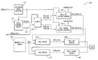
- FIG. 1is a functional block diagram of an off chip driver (OCD) impedance adjustment circuit 100 according to one embodiment of the present invention.
- OCDoff chip driver
- an external circuitsuch as a memory controller applies a drive strength adjustment word DRADJ ⁇ 0:3> to the adjustment circuit 100 , and in response to the applied DRADJ ⁇ 0:3> word a pair of up/down (UP/DN) counters 102 and 104 develop respective drive strength words to thereby adjust the output drive strength of a pair of output drivers 106 and 108 , as will be discussed in more detail below.
- UP/DNup/down
- a latch 110latches the drive strength adjustment word DRADJ ⁇ 0:3> applied on a data bus DQ responsive to an OCD clock signal OCDCLK from a write control circuit 112 .
- the write control circuit 112develops a number of control signals 114 that are applied to control various components in the adjustment circuit 100 , as will be described in more detail below.
- the DRADJ ⁇ 0:3> wordis a four-bit word in the example of FIG. 1 , and the latch 110 outputs two of the latched adjustment bits as pull-up bits PUP-UP and PUP-DN and outputs the other two of the latched adjustment bits as pull-down bits PDN-UP and PDN-DN.
- the pull-up bits PUP-UP, PUP-DNare applied to the pull-up UP/DN counter 102 , which increments or decrements a pull-up drive strength count PUP-DR ⁇ 0:3> responsive to the applied adjustment bits.
- the pull-down bits PDN-UP, PDN-DNare applied to the pull-down UP/DN counter 104 , which increments or decrements a pull-down drive strength word PDN-DR ⁇ 0:3> responsive to the applied adjustment bits.
- the pull-up UP/DN counter 102operates in either an adjustment or default mode of operation as determined by the control signals 114 from the write control circuit 112 .
- each counter 102 , 104operates as previously described to increment or decrement the pull-up and pull-down counts PUP-DR ⁇ 0:3>, PDN-DR ⁇ 0:3>, while in the default mode the counters utilize a corresponding pull-up fuse adjustment word FADJ-PU ⁇ 0:3> or pull-down fuse adjustment word FADJ-PD ⁇ 0:3> to generate the corresponding drive strength count PUP-DR ⁇ 0:3>, PDN-DR ⁇ 0:3>.
- An extended mode register 116stores several bits associated with the drive strength adjustment process, including a half drive strength bit HDRV which, when set, causes the drive strength of the drivers 106 , 108 to be set to half the default value defined by the FADJ-PU ⁇ 0:3>, FADJ-PD ⁇ 0:3> words. Other bits in the extended mode register 116 determine whether the write control circuit 112 controls the components in the circuit 100 to adjust the drive strength of the drivers 106 , 108 or utilize the default drive determined by the FADJ-PU ⁇ 0:3>, FADJ-PD ⁇ 0:3> words, as will be discussed in more detail below.
- the extended mode register 116is a standard component in SDRAMs, with the memory controller loading bits into the register to define various operating parameters of the SDRAM.
- bits in the extended mode register 116control the enabling or disabling of data strobes provided by the SDRAM, and the enabling or disabling of a delay-locked loop synchronization circuit (not shown) in the SDRAM, as well as determining other operational parameters of the SDRAM as will be understood by those skilled in the art.
- a predriver 118receives the PUP-DR ⁇ 0:3> count from the counter 102 and also receives a data signal designated QINi from a memory-cell array 120 . In response to the PUP-DR ⁇ 0:3> count and the QINi signal, the predriver 118 develops a pull-up drive strength word PUPi ⁇ 0:4> that is applied to the output driver 102 .
- One bit of the five bit PUPi ⁇ 0:4> wordis determined by the logic state of the QINi signal, while the other four bits each have values determined by the QINi signal and the applied PUP-DR ⁇ 0:3> word, and function to set the drive strength of the output driver 106 .
- a predriver 122receives the PDN-DR ⁇ 0:3> word from the counter 104 and also receives the QINi signal, and operates in the same way as the predriver 118 to generate a pull-down drive strength word PDN ⁇ 0:4> that is applied to the output driver 104 .
- PDN ⁇ 0:4> wordone of the five bits corresponds to the QINi signal while the other four bits set the drive strength of the corresponding output driver 106 , 108 .
- the drive strength of each driver 106 , 108may be set to one of sixteen values in the embodiment of FIG.
- Each predriver 118 , 122also provides for slew rate compensation to precisely control when the signals forming the PUPi ⁇ 0:4>, PDN ⁇ 0:4> words are applied to the drivers 106 , 108 , which in turn controls the precise time at which each driver drives the data line 124 high or low, as will be discussed in more detail below.
- One of the output drivers 106 , 108is activated in response to the applied PUPi ⁇ 0:4>, PDN ⁇ 0:4> word, and the activated driver 106 , 108 applies data a data line 124 of the data bus DQ. Whether each driver 106 , 108 is activated to drive the data line 124 depends on the state of the one bit in the PUPi ⁇ 0:4>, PDN ⁇ 0:4> words corresponding to the QINi signal. When the QINi signal is low, the pull-up driver 106 is activated to drive the data line 124 high with a drive strength set by the other four bits in the PUPi ⁇ 0:4> word. Conversely, when the QINi signal is high the pull-down driver 108 is activated to drive the data line 124 low with a drive strength set by the other four bits in the PDN ⁇ 0:4> word.
- the circuit 100operates in two modes, an adjustment mode and a default mode, as determined by bits in the extended mode register 116 .
- the write control circuit 112develops the control signals 114 that cause the counters 102 , 104 to develop the PUP-DR ⁇ 0:3>, PDN-DR ⁇ 0:3> counts using the corresponding default FADJ-PU ⁇ 0:3>, FADJ-PD ⁇ 0:3> words.
- the control circuit 112does not apply the OCDCLK signal to clock the latch.
- PUP-DR ⁇ 0:3>, PDN-DR ⁇ 0:3> countsmay be termed default words, and are applied to the predrivers 118 , 122 which, in turn, generate the PUPi ⁇ 0:4> and PDN ⁇ 0:4> words using the default values and an applied QINi signal.
- Each driver 106 , 108thus drives the data line 124 with a default drive strength defined by the PUP-DR ⁇ 0:3>, PDN-DR ⁇ 0:3> counts from the counters 102 , 104 .
- the pull-up driver 106drives the data line 124 high with the default drive strength
- the pull-down driver 108drives the data line low with the default drive strength when the QINi signal is high.
- the default drive strength of each driver 106 , 108is one of the 16 possible values.
- the four bits in each of the PUPi ⁇ 0:4>, PDN ⁇ 0:4> that set the drive strength of the corresponding driver 106 , 108could have the values (0111), which would be half way between a minimum value of (0000) and a maximum value of (1111).
- the write control circuit 112develops the control signals 114 and OCDCLK signal to cause the counters 102 , 104 to adjust the values of the PUP-DR ⁇ 0:3>, PDN-DR ⁇ 0:3> counts using the DRADJ ⁇ 0:3> words. More specifically, the memory controller (not shown) loads bits into the extended mode register 116 to place the circuit 100 into the adjustment mode, and also initially develops control signals 114 that cause each counter 102 , 104 to set the PUP-DR ⁇ 0:3>, PDN-DR ⁇ 0:3> counts to their default values as determined by the corresponding FADJ-PU ⁇ 0:3>, FADJ-PD ⁇ 0:3> words. The memory controller thereafter sequentially applies DRADJ ⁇ 0:3> words on the data bus DQ, and the write control circuit 112 develops the OCDCLK signal to clock each DRADJ ⁇ 0:3> word into the latch 110 .
- the latch 110For each latched DRADJ ⁇ 0:3> word, the latch 110 outputs the corresponding PUP-UP, PUP-DN and PDN-UP, PDN-DN bits to the counters 102 , 104 .
- the counter 102In response to the applied PUP-UP, PUP-DN bits, the counter 102 either increments or decrements the PUP-DR ⁇ 0:3> count.
- the default value of the PUP-DR ⁇ 0:3> countwas 0111 and the count is decremented by one, the new value of the count is 0110.
- the counter 104operates in the same way responsive to the PDN-UP, PDN-DN bits to increment or decrement the PDN-DR ⁇ 0:3> count.
- the adjusted PUP-DR ⁇ 0:3>, PDN-DR ⁇ 0:3> countsare applied to the predrivers 118 , 122 along with the QINi signal from the memory-cell array.
- the predriver 118develops the PUPi ⁇ 0:4> word that is applied to the output driver 106
- the predriver 122develops the PDN ⁇ 0:4> word in the same manner responsive to the PDN-DR ⁇ 0:3> count and QINi signal.
- one of the drivers 106 , 108is activated and drives the data line 124 high or low.
- the driver 108is activated and drives the data line 124 low, while the driver 106 is activated if the QINi signal is low to thereby drive the data line high.
- the memory controllercaptures the data signal placed on the data line 124 responsive to a data strobe signal DQS (not shown) that is output coincident with the data signal, and the captured data signal is utilized in determining a final drive strength of the drivers 106 , 108 , as will be discussed in more detail below.
- the memory controllerrepeats the process just described for a number of DRADJ ⁇ 0:3> words.
- the latch 110captures the word and outputs the corresponding PUP-UP, PUP-DN, PDN-UP, PDN-DN bits to increment or decrement and the counters 102 , 104 , and the predrivers 118 , 122 and output drivers 106 , 108 thereafter operate as previously described to adjust the drive strength of the output drivers and drive the data line 124 .
- Each DRADJ ⁇ 0:3> wordresults in the drive strength of each driver 106 , 108 either being incremented or decremented from its prior value, or results in the drive strength remaining the same.
- the memory controllercontinues operating in this manner to adjust the strength of the drivers 106 , 108 to desired values.
- the specific process utilized by the controller in determining a final value for the drive strengthis not relevant to the present invention and may vary, and thus, for the sake of brevity, such a process will not be described in more detail.
- the OCD impedance adjustment circuit 100allows the controller to easily adjust the drive strengths of the drivers 106 , 108 to such desired values. Note that the extended mode register 116 and memory-cell array 120 are shown in FIG. 1 for convenience in describing the operation of the OCD impedance adjustment circuit 100 , and need not be considered components of the impedance adjustment circuit.
- FIG. 2is a schematic of the write control circuit 112 of FIG. 1 according to one embodiment of the present invention.
- the write control circuit 112receives a power-up reset signal DQRST from circuitry (not shown) which is activated upon power-up of a memory device containing the write control circuit 112 .
- the DQRST signalhas a high logic level during power up, but is typically at a low logic level otherwise.
- the active DQRST signal applied to a NOR gate 208causes a default signal DEFAULT output by an inverter 210 to become active high, which in turn forces the OCDCLK signal high as well.
- a default drive signal OCDRhas a logic level responsive to corresponding bits loaded in the extended mode register 116 , as previously discussed, and is used to force a default drive strength.
- a half drive signal HDRVis used to set the drive strength of the output drivers 106 , 108 to be approximately one half the default drive strengths, and has a logic level responsive to corresponding bits loaded in the extended mode register 116 .
- the HDRV signalis applied through series-connected delay circuits 200 – 204 as shown to an XOR gate 206 to generate a pulse that sets the counters 102 and 104 to their default values when the HDRV is initially set. In the event that the OCDR and DQRST signals, and the HDRV pulse are all inactive, drive strength adjustments can be made.
- a reset signal OCDW applied through an inverter 218 to a reset input of a first RS latch 212 formed by cross-coupled NAND gates 214 , 216is pulsed high to prepare the write control circuit 112 for a data write operation in order to load an OCD adjustment control word.
- the DEFAULT signalis also applied to the NAND gate 216 through an inverter 222 .
- the OCDCLK signalis forced to a low logic level.
- a subsequent write commandwill now cause a set signal WRH, which is applied through an inverter 220 to a set input of the latch 212 and also to a reset input of a second RS latch 228 formed by cross-coupled NAND gates 230 and 232 , to pulse high when the OCD adjustment control word is valid.
- the OCDCLK signalis forced back to a high logic level via the inverters 224 , 226 to latch the OCD adjustment control word. While the WRH pulse is high, a strobe pulse STRB remains in a low logic state.
- an active STRB pulseis output in response to the output of the NAND gate 232 being applied to an inverter 234 , delay circuit 236 , NOR gate 238 , and inverters 240 , 242 , after the OCD adjustment word has been latched.
- the DEFAULT and STRB signalsare applied to control other components in the adjustment circuit 100 .
- the active STRB pulseforces the counters 102 , 104 to respond to the latched drive adjustment word.
- FIG. 3is a schematic of the latch 110 of FIG. 1 according to one embodiment of the present invention.
- the latch 110includes four flip-flops 300 – 306 that receive respective bits of the DRADJ ⁇ 0:3> word and latch these respective bits responsive to the OCDCLK signal.
- the flip-flops 300 – 306are reset responsive to the DQRST signal, with each flip-flop driving a corresponding output inactive low responsive to the DQRST signal going active.
- the latched DRADJ ⁇ 0>-DRADJ ⁇ 1> bitsare output from the flip-flops 300 and 302 as the PDN-DN and PDN-UP bits, respectively, and are applied to the pull-down UP/DN counter 104 ( FIG. 1 ).
- the latched DRADJ ⁇ 2>-DRADJ ⁇ 3> bitsare output from the flip flops 304 and 306 as the PUP-DN and PUP-UP bits, respectively, and are applied to the pull-up UP/DN counter 102 ( FIG. 1 ).
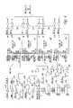
- FIG. 4is a schematic of each of the counters 102 , 104 of FIG. 1 according to one embodiment of the present invention.
- the counter in FIG. 4will be referred to as the pull-up UP/DN counter 102 for ease of description.
- the counter 102includes four counter bit circuits 400 – 406 , with each counter bit circuit having respective complementary outputs DR ⁇ 0>, DRi ⁇ 0>-DR ⁇ 3>, DRi ⁇ 3> that are applied through series-connected inverters 408 to generate a corresponding bits of the PUP-DR ⁇ 0:3> count.
- each counter bit circuit 400 – 406operates in the default mode and one of the bits FADJ ⁇ 0>-FADJ ⁇ 3> is provided as the corresponding DR ⁇ 0:3>, DRi ⁇ 0:3> outputs, with the specific output provided depending upon the state of the HDRV signal.
- the counter bit circuit 400latches the FADJ ⁇ 0> bit responsive to the STRB signals and outputs the latched bit as the DR ⁇ 0>, DRi ⁇ 0> bits.
- the counter bit circuit 400latches the FADJ ⁇ 1> bit responsive to the STRB signals and outputs this latched bit as the DR ⁇ 0>, DRi ⁇ 0> bits. This results in the bits of the FADJ ⁇ 0:3> word being shifted to the right one place when the HDRV signal is active, which divides the value of the FADJ ⁇ 0:3> word by two.
- each counter bit circuit 400 – 406When the DEFAULT signals are inactive, each counter bit circuit 400 – 406 operates in the adjustment mode and either toggles or leaves the same the corresponding DR, DRi bits responsive to a toggle signal PRE-TGL0-3 applied to each of the counter bit circuits.
- a NOR gategenerates the PRE-TGL-0 signal applied to circuit 400 responsive to three input signals.
- An XOR gate 416receives the PUP-UP, PUP-DN bits and applies an active input to the NOR gate 414 , and otherwise provides an inactive input to the NOR gate.
- a NAND gate 418 and NOR gate 420operate in combination as a full-up count detection circuit, with the NOR gate 420 applying a high input to the NOR gate 414 when the PUP-DR ⁇ 0:3> count has its maximum value of (1111).
- a NAND gate 422 and NOR gate 424operate in combination as a full-down count detection circuit, with the NOR gate 424 applying a high input to the NOR gate 414 when the PUP-DR ⁇ 0:3> count has its minimum value of (0000).
- the PUP-UP signalis applied through an inverter 426 to enable the NOR gate 420 when this signal is high and the PUP-DN signal is applied through an inverter 428 to enable the NOR gate 424 when this signal is high.
- the NOR gate 420is enabled when the PUP-DR ⁇ 0:3> count is being incremented to determine whether the count has reached its maximum value, and the NOR gate 424 is enabled when the PUP-DR ⁇ 0:3> count is being decremented to determine whether the count has reached its minimum value.
- the NOR gate 414drives the PRE-TGL-0 signal low, which disables the toggling of the DR ⁇ 0> bits responsive to the STRB signals.
- the PRE-TGL-0 signalis high, meaning the PUP-UP and PUP-DN signals have complementary values and the PUP-DR ⁇ 0:3> count is not at its maximum or minimum, the counter bit circuit 400 toggles the bit DR ⁇ 0> responsive to the STRB signals.
- a transmission gate 430receives the PUP-UP, PUP-DN signals and outputs one of the signals responsive to the DR ⁇ 0>, DRi ⁇ 0> bit from the counter bit circuit 400 , with the output PUP-UP, PUP-DN signal being applied to a NAND gate 432 .
- the PRE-TGL-0 signalis also applied to enable the NAND gate 432 , and the output of the NAND gate 432 is applied through an inverter 434 to generate a toggle signal PRE-TGL-1 applied to the counter bit circuit 402 .
- the counter bit circuit 402operates in the same way as described for the circuit 400 responsive to the PRE-TGL-1 signal and other signals applied to the circuit.
- Components 436 – 446operate in the same way as described for the components 430 – 434 to generate a PRE-TGL-2 signal applied to the counter bit circuit 404 and a PRE-TGL-3 signal applied to the counter bit circuit 406 .
- the counter 102increments the PUP-DR ⁇ 0:3> count by one, and when the PUP-UP signal is 0 and PUP-DN signal is 1 the counter decrements this count by one. Note that whenever the PRE-TGL-0 signal is inactive low, meaning that counter bit circuit 400 will not toggle the least significant bit DR ⁇ 0>, all other counter bit circuit 402 – 406 will be similarly disabled.
- the theory of operation of the counter 102will now be briefly described with reference to FIG. 4 , although one skilled in the art will understand such operation merely from the illustrated schematic. In incrementing the PUP-DR ⁇ 0:3> count, the least significant bit DR ⁇ 0> alternately toggles between 0 and 1.
- the DR ⁇ 1> bitwill not toggle because the DR ⁇ 0> bit is a 0.
- this bitwill only toggle when all lesser significant bits are 1's. For example, the count (1010) will increment to (1011) and the DR ⁇ 2> did not toggle because the DR ⁇ 0> and DR ⁇ 1> lesser significant bits were not both 1's.
- the countincrements to 1100, with the DR ⁇ 2> bit toggling to a 1 because both the DR ⁇ 0> and DR ⁇ 1> bits are 1's. Note that in this example the DR ⁇ 3> bit does not toggle since not all lesser significant bits are 1's.
- the operation in decrementing the PUP-DR ⁇ 0:3> countis similar and will be understood by those skilled in the art.
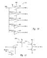
- FIG. 5is a schematic of one of the individual counter bit circuits 400 – 406 forming the counter 102 of FIG. 4 .
- the depicted circuitis assumed to be the counter bit circuit 400 .
- a transmission gate 500applies the PRE-TGL signal to one input of a NAND gate 502 and also through series connected inverters 504 , 506 to a second input of the transmission gate.
- the transmission gate 500 and inverters 504 , 506operate as a latch to latch the previous value of the PRE-TGL signal and provide this signal on a node 507 when the STRB signals go active.
- the NAND gate 502When the PRE-TGL signal is high, the NAND gate 502 is enabled and drives its output low when the STRB signals go active.
- the output of the NAND gate 502is applied directly and through an inverter 508 to transmission gates 510 , 512 .
- the transmission gate 510 and a pair of inverters 514 , 516operate as a first latch having an output L 1
- the transmission gate 512 and a pair of inverters 518 , 520operate as a second latch having an output L 2 .
- the output L 2 of the second latchis applied directly and through an inverter 522 to generate DRi ⁇ 0> and DR ⁇ 0> bits.
- the NAND gatedrives its output low responsive to the STRB signals going active and drives its output high responsive to the STRB signals going inactive.
- the transmission gate 512is enabled and applies the output L 1 to the inverter 518 which, in turn, drives the output L 2 high.
- the output L 2is applied through the inverter 520 and through the transmission gate 512 to the input of the inverter 518 such that the second latch stores the value of L 2 , which is the complementary value of L 1 .
- the output L 2is applied through the inverter 520 to an input of the transmission gate 510 .
- the transmission gate 510is enabled and the value of L 2 is applied through the inverter 520 , through the transmission gate 510 , and through the inverter 514 to the output L 1 of the first latch.
- this new value for the output L 1which is same as the current value of L 2 , will be applied through the inverter to provide the complement of this signal as the new L 2 value.
- the first and second latchesare merely serially-connected latches with the output of the second latch being inverted and fed back to the input of the first latch, as will be appreciated by those skilled in the art.
- a gate 524is enabled to force L 2 to a value determined by the HDRV signal and the FADJ ⁇ 0:1> bits, as previously described. It will be appreciated by those ordinarily skilled in the art that the gate 524 has higher drive than the transmission gate 512 to overwrite the second latch for L 2 .
- FIG. 6is a schematic illustrating one embodiment of the output drivers 106 , 108 of FIG. 1 .
- the output driver 106includes five PMOS transistors 600 – 608 coupled between a supply voltage VCC and the data line 124 , each PMOS transistor receiving a respective bit of the PUPi ⁇ 0:4> word from the predriver 118 ( FIG. 1 ). When any of the PUPi ⁇ 0>– ⁇ 4> bits is low, the corresponding PMOS transistor 600 – 608 turns on, driving the data line 124 high through that transistor.
- the drive strength of the driver 106is determined by the number of transistors 600 – 608 that are turned on.
- the PMOS transistor 600provides the minimum drive strength of the driver 106 in that if the driver is activated to drive the data line 124 high, and the data line will be driven high through at least the PMOS transistor 600 .
- the output driver 108includes five NMOS transistors 610 – 618 coupled between ground and the data line 124 , each NMOS transistor receiving a respective bit of the PDN ⁇ 0:4> word from the predriver 122 ( FIG. 1 ). When any of the PDN ⁇ 0>– ⁇ 4> bits is high, the corresponding NMOS transistor 610 – 618 turns on, driving the data line 124 low through that transistor.
- the drive strength of the driver 108is determined by the number of transistors 610 – 618 that are turned on, and the NMOS transistor 610 provides the minimum drive strength of the driver in that if the driver will drive the data line low through at least the NMOS transistor 610 .
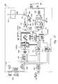
- FIG. 7is a functional schematic of the pre-drivers 118 , 122 of FIG. 1 according to one embodiment of the present invention.
- the QINi signal from the memory-cell array 120( FIG. 1 ) is stored by a latch 700 formed by cross-coupled inverters 702 , 704 and applied to first inputs of a NAND gate 706 and a NOR gate 708 .
- a latch 710 formed by cross-coupled inverters 712 , 714latches an external signal LQEDi. When the LQEDi is active low, the latch 710 applies a high output to enable the NAND gate 706 and is applied through a transmission gate 716 to enable the NOR gate 708 .
- An enable drive signal ENDRVis applied to a PMOS transistor 718 , and when activated forces the LQEDi signal high to thereby disable the NAND gate 706 and NOR gate 708 .
- the NAND gate 706applies an active low output through series-connected inverters 720 , 722 to an input of an inverter 724 formed by a PMOS transistor 726 and an NMOS transistor 728 .
- the PMOS transistor 726turns on driving an input of a pull-up circuit 730 high.
- the NAND gate 706drives its output high and the inverter 724 drives the input of the pull-up circuit 730 low.
- the pull-up circuit 730also receives the PUP-DR ⁇ 0:3> count from the counter 102 ( FIG.
- a resistor network 731is coupled to a low terminal of the pull-up circuit 730 and determines a rate at which the circuit drives each of the bits in the PUPi ⁇ 0:4> word to its desired value, as explained in more detail below.
- the nor gate 708In response to the low QINi signal, the nor gate 708 also applies a low output through series-connected inverters 732 and 734 to an input of an inverter 736 formed by a PMOS transistor 738 and an NMOS transistor 740 .
- the inverter 736operates in the same way as the inverter 724 in response to the low input to drive an input of a pull-down circuit 742 high.
- the pull-down circuit 742also receives the PDN-DR ⁇ 0:3> count from the counter 104 ( FIG. 1 ), and in response to this count and the output of the inverter 736 , the pull-down circuit 742 generates the PDN ⁇ 0:4> word.
- a resistor network 741is coupled to a high terminal of the pull-down circuit 742 and determines a rate at which the circuit drives each of the bits in the PDN ⁇ 0:4> word to its desired value, as explained in more detail below.
- FIG. 8is a schematic illustrating one embodiment of the pull-up circuit 730 of FIG. 7 .
- the pull-up circuit 730includes a plurality of inverters 800 – 808 each receiving an input signal IN corresponding to the output of the inverter 724 in FIG. 7 .
- the value of the input signal INis the complement of the value of the QINi signal, as indicated in parentheses in FIG. 8 .
- Each inverter 800 – 808receives an enable signal which, when active, allows for normal operation of the inverter and when inactive drives the output of the inverter high independent of the input signal IN.
- the enable signal of the inverter 800is coupled to a supply voltage VCC to permanently enable the inverter and cause the inverter to provide the complement of the IN signal as the PUPi ⁇ 4> bit.
- the enable signals of the inverters 802 – 808are supplied by the respective PUP-DR ⁇ 0>-PUP-DR ⁇ 3> bits from the counter 102 .
- a given bitis high (i.e., the logic 1)
- the corresponding inverter 802 – 808is enabled and the inverter drives the corresponding PUPi ⁇ 0>-PUPi ⁇ 3> to a level determined by the value of the IN signal.
- Each inverter 800 – 808also includes a LOW terminal that is coupled to the resistor network 731 of FIG. 7 .
- FIG. 9is a schematic of each of the inverters 800 – 808 forming the pull-up circuit 730 of FIG. 7 according to one embodiment of the present invention.
- the PUP-DR ⁇ 3> bitcorresponds to the enable signal for the inverter 802 and is applied directly and through an inverter 900 to a transmission gate 902 .
- the IN signalis applied through the transmission gate 902 to an input of an inverter 904 formed by a PMOS transistor 906 and an NMOS transistor 908 coupled between a supply voltage VCC and the LOW terminal which, as previously discussed, is coupled to the resistor network 731 of FIG. 7 .
- the output of the inverter 904corresponds to the PUPi ⁇ 3> bit applied to the pull-up driver 106 of FIG. 6 .
- the output of the inverter 900is further applied to an NMOS transistor 910 coupled between the input of the inverter 904 and ground.
- the transmission gate 902is enabled and the IN signal is applied to the input of the inverter 904 which, in turn, generates the PUPi ⁇ 3> bit having a value that is the complement of the IN signal.
- the value of the resistor network 731 coupled to the LOW terminal of the inverter 904determines the rate at which the inverter drives the PUPi ⁇ 3> bit to its desired value and thus controls the slew rate of the inverter.
- the NMOS transistor 910is turned off when the PUP-DR ⁇ 3> bit is active high.
- the transmission gate 902When the PUPi ⁇ 3> bit is inactive low (i.e., is a logic 0), the transmission gate 902 is disabled and the transistor 910 turns on driving the input of the inverter 904 low which, in turn, drives the PUPi ⁇ 3> bit high independent of the IN signal.
- FIG. 10is a schematic illustrating one embodiment of the pull-down circuit 742 of FIG. 7 .
- the pull-down circuit 742includes five inverters 1000 – 1008 coupled in much the same way as the inverters 800 – 808 previously described with reference to FIG. 8 , and thus, the interconnection of these inverters will not again be described in detail.
- the inverter 1000is permanently enabled while each of the other inverters 1002 – 1008 is enabled by a respective PDN-DR signal.
- each inverter 1002 – 1008when a given bit is high (i.e., the logic 1), and the corresponding inverter 1002 – 1008 is enabled when the corresponding PDN-DR ⁇ 3>-PDN-DR ⁇ 0> bit is a 1, the inverter drives the corresponding PDN ⁇ 0>-PDN ⁇ 3> bit to a level determined by the value of the IN signal.
- Each inverter 1002 – 1008also includes a HIGH terminal that is coupled to the resistor network 741 of FIG. 7 . When disabled, each of the inverters drives the corresponding PDN ⁇ 3>-PDN ⁇ 0> bit low regardless of the signal level of the IN signal applied to its input.
- FIG. 11is a schematic of each of the inverters 1000 – 1008 forming the pull-down circuit 742 of FIG. 10 according to one embodiment of the present invention.
- the inverter 1002is assumed to be illustrated in FIG. 11 , and includes components 1100 – 1108 that function in substantially the same way as components 900 – 908 in the inverter 802 of FIG. 9 , and thus will not again be described in detail.
- the inverter 1002includes a PMOS transistor 1110 coupled between a supply voltage VCC and the input of the inverter 1104 .
- the PMOS transistor 1110turns on driving the input of the inverter 1104 high which, in turn, drives the PDN ⁇ 3> bit low.
- the HIGH terminal of the inverter 1002is coupled to the resistor network 741 of FIG. 7 , and the value of the resistor network determines the rate at which the inverter drives the PDN ⁇ 3> bit to its desired value, and thus, controls the slew rate of the inverter 1002 .
- FIG. 12is a functional block diagram of a memory device 1200 including the (OCD) impedance adjustment circuit 100 of FIG. 1 .
- the memory device 1200 in FIG. 12is a double-data rate (DDR) synchronous dynamic random access memory (“SDRAM”), although the principles described herein are particularly applicable to DDR II DRAM or any other integrated circuit that may include OCD impedance adjustment.
- DDRdouble-data rate
- SDRAMsynchronous dynamic random access memory
- the memory device 1200includes an address register 1202 that receives row, column, and bank addresses over an address bus ADDR, with a memory controller (not shown) typically supplying the addresses.
- the address register 1202receives a row address and a bank address that are applied to a row address multiplexer 1204 and bank control logic circuit 1206 , respectively.
- the row address multiplexer 1204applies either the row address received from the address register 1202 or a refresh row address from a refresh counter 1208 to a plurality of row address latch and decoders 1210 A–D.
- the bank control logic 1206activates the row address latch and decoder 1210 A–D corresponding to either the bank address received from the address register 1202 or a refresh bank address from the refresh counter 1208 , and the activated row address latch and decoder latches and decodes the received row address.
- the activated row address latch and decoder 1210 A–Dapplies various signals to a corresponding memory bank 1212 A–D to thereby activate a row of memory cells corresponding to the decoded row address.
- Each memory bank 1212 A–Dincludes a memory-cell array having a plurality of memory cells arranged in rows and columns, and the data stored in the memory cells in the activated row is stored in sense amplifiers in the corresponding memory bank.
- the row address multiplexer 1204applies the refresh row address from the refresh counter 1208 to the decoders 1210 A–D and the bank control logic circuit 1206 uses the refresh bank address from the refresh counter when the memory device 1200 operates in an auto-refresh or self-refresh mode of operation in response to an auto- or self-refresh command being applied to the memory device 1200 , as will be appreciated by those skilled in the art.
- a column addressis applied on the ADDR bus after the row and bank addresses, and the address register 1202 applies the column address to a column address counter and latch 1214 which, in turn, latches the column address and applies the latched column address to a plurality of column decoders 1216 A–D.
- the bank control logic 1206activates the column decoder 1216 A–D corresponding to the received bank address, and the activated column decoder decodes the applied column address.
- the column address counter and latch 1214either directly applies the latched column address to the decoders 1216 A–D, or applies a sequence of column addresses to the decoders starting at the column address provided by the address register 1202 .
- the activated column decoder 1216 A–Dapplies decode and control signals to an I/O gating and data masking circuit 1218 which, in turn, accesses memory cells corresponding to the decoded column address in the activated row of memory cells in the memory bank 1212 A–D being accessed.
- data being read from the addressed memory cellsis coupled through the I/O gating and data masking circuit 1218 to a read latch 1220 .
- the I/O gating and data masking circuit 1218supplies N bits of data to the read latch 1220 , which then applies two N/2 bit words to a multiplexer 1222 .
- the circuit 1218provides 64 bits to the read latch 1220 which, in turn, provides two 32 bits words to the multiplexer 1222 .
- a data driver 1224sequentially receives the N/2 bit words from the multiplexer 1222 and also receives a data strobe signal DQS from a strobe signal generator 1226 and a delayed clock signal CLKDEL from a delay-locked loop (DLL) 1227 .
- the DQS signalis used by an external circuit such as a memory controller (not shown) in latching data from the memory device 1200 during read operations.
- the data driver 1224sequentially outputs the received N/2 bits words as a corresponding data word DQ, each data word being output in synchronism with a rising or falling edge of a CLK signal that is applied to clock the memory device 1200 .
- the data driver 1224also outputs the data strobe signal DQS having rising and falling edges in synchronism with rising and falling edges of the CLK signal, respectively.
- Each data word DQ and the data strobe signal DQScollectively define a data bus DATA.
- the CLKDEL signal from the DLL 1227is a delayed version of the CLK signal, and the DLL 1227 adjusts the delay of the CLKDEL signal relative to the CLK signal to ensure that the DQS signal and the DQ words are placed on the DATA bus in synchronism with the CLK signal.
- the DATA busalso includes masking signals DM 0 -M, which will be described in more detail below with reference to data write operations.
- an external circuitsuch as a memory controller (not shown) applies N/2 bit data words DQ, the strobe signal DQS, and corresponding data masking signals DM 0 -X on the data bus DATA.
- a data receiver 1228receives each DQ word and the associated DM 0 -X signals, and applies these signals to input registers 1230 that are clocked by the DQS signal. In response to a rising edge of the DQS signal, the input registers 1230 latch a first N/2 bit DQ word and the associated DM 0 -X signals, and in response to a falling edge of the DQS signal the input registers latch the second N/2 bit DQ word and associated DM 0 -X signals.
- the input register 1230provides the two latched N/2 bit DQ words as an N-bit word to a write FIFO and driver 1232 , which clocks the applied DQ word and DM 0 -X signals into the write FIFO and driver in response to the DQS signal.
- the DQ wordis clocked out of the write FIFO and driver 1232 in response to the CLK signal, and is applied to the I/O gating and masking circuit 1218 .
- the I/O gating and masking circuit 1218transfers the DQ word to the addressed memory cells in the accessed bank 1212 A–D subject to the DM 0 -X signals, which may be used to selectively mask bits or groups of bits in the DQ words (i.e., in the write data) being written to the addressed memory cells.
- a control logic and command decoder 1234receives a plurality of command and clocking signals over a control bus CONT, typically from an external circuit such as a memory controller (not shown).
- the command signalsinclude a chip select signal CS*, a write enable signal WE*, a column address strobe signal CAS*, and a row address strobe signal RAS*, while the clocking signals include a clock enable signal CKE* and complementary clock signals CLK, CLK*, with the “*” designating a signal as being active low.
- the command signals CS*, WE*, CAS*, and RAS*are driven to values corresponding to a particular command, such as a read, write, or auto-refresh command.
- the command decoder 1234In response to the clock signals CLK, CLK*, the command decoder 1234 latches and decodes an applied command, and generates a sequence of clocking and control signals that control the components 1202 – 1232 to execute the function of the applied command.
- the clock enable signal CKEenables clocking of the command decoder 1234 by the clock signals CLK, CLK*.
- the command decoder 1234latches command and address signals at positive edges of the CLK, CLK* signals (i.e., the crossing point of CLK going high and CLK* going low), while the input registers 1230 and data drivers 1224 transfer data into and from, respectively, the memory device 1200 in response to both edges of the data strobe signal DQS and thus at double the frequency of the clock signals CLK, CLK*. This is true because the DQS signal has the same frequency as the CLK, CLK* signals.
- the memory device 1200is referred to as a double-data-rate device because the data words DQ being transferred to and from the device are transferred at double the rate of a conventional SDRAM, which transfers data at a rate corresponding to the frequency of the applied clock signal.
- the detailed operation of the control logic and command decoder 1234 in generating the control and timing signalsis conventional, and thus, for the sake of brevity, will not be described in more detail.
- the control logic and command decoder 1234would typically supply the external signals discussed with reference to the OCD impedance adjustment circuit 100 of FIG. 1 , and the OCD impedance adjustment circuit 100 would typically be included with the data drivers 1224 previously discussed.
- the mode registers 1236include the extended mode register 116 of FIG. 1 and the memory arrays 1212 A–D correspond to the memory-cell array 120 of FIG. 1 .
- FIG. 13is a block diagram of a computer system 1300 including computer circuitry 1302 including the memory device 1200 of FIG. 12 .
- the computer circuitry 1302is coupled through address, data, and control buses to the memory device 1200 to provide for writing data to and reading data from the memory device.
- the computer circuitry 1302includes circuitry for performing various computing functions, such as executing specific software to perform specific calculations or tasks.
- the computer system 1300includes one or more input devices 1304 , such as a keyboard or a mouse, coupled to the computer circuitry 1302 to allow an operator to interface with the computer system.
- the computer system 1300also includes one or more output devices 1306 coupled to the computer circuitry 1302 , such as output devices typically including a printer and a video terminal.
- One or more data storage devices 1308are also typically coupled to the computer circuitry 1302 to store data or retrieve data from external storage media (not shown). Examples of typical storage devices 1308 include hard and floppy disks, tape cassettes, compact disk read-only (CD-ROMs) and compact disk read-write (CD-RW) memories, and digital video disks (DVDs).
- typical storage devices 1308include hard and floppy disks, tape cassettes, compact disk read-only (CD-ROMs) and compact disk read-write (CD-RW) memories, and digital video disks (DVDs).
Landscapes
- Physics & Mathematics (AREA)
- Engineering & Computer Science (AREA)
- Computer Hardware Design (AREA)
- Computing Systems (AREA)
- General Engineering & Computer Science (AREA)
- Mathematical Physics (AREA)
- Dram (AREA)
Abstract
Description
Claims (50)
Priority Applications (3)
| Application Number | Priority Date | Filing Date | Title |
|---|---|---|---|
| US10/726,312US7019553B2 (en) | 2003-12-01 | 2003-12-01 | Method and circuit for off chip driver control, and memory device using same |
| US11/351,047US7463052B2 (en) | 2003-12-01 | 2006-02-08 | Method and circuit for off chip driver control, and memory device using same |
| US12/329,132US7936181B2 (en) | 2003-12-01 | 2008-12-05 | Method and circuit for off chip driver control, and memory device using same |
Applications Claiming Priority (1)
| Application Number | Priority Date | Filing Date | Title |
|---|---|---|---|
| US10/726,312US7019553B2 (en) | 2003-12-01 | 2003-12-01 | Method and circuit for off chip driver control, and memory device using same |
Related Child Applications (1)
| Application Number | Title | Priority Date | Filing Date |
|---|---|---|---|
| US11/351,047ContinuationUS7463052B2 (en) | 2003-12-01 | 2006-02-08 | Method and circuit for off chip driver control, and memory device using same |
Publications (2)
| Publication Number | Publication Date |
|---|---|
| US20050116736A1 US20050116736A1 (en) | 2005-06-02 |
| US7019553B2true US7019553B2 (en) | 2006-03-28 |
Family
ID=34620500
Family Applications (3)
| Application Number | Title | Priority Date | Filing Date |
|---|---|---|---|
| US10/726,312Expired - Fee RelatedUS7019553B2 (en) | 2003-12-01 | 2003-12-01 | Method and circuit for off chip driver control, and memory device using same |
| US11/351,047Expired - Fee RelatedUS7463052B2 (en) | 2003-12-01 | 2006-02-08 | Method and circuit for off chip driver control, and memory device using same |
| US12/329,132Expired - Fee RelatedUS7936181B2 (en) | 2003-12-01 | 2008-12-05 | Method and circuit for off chip driver control, and memory device using same |
Family Applications After (2)
| Application Number | Title | Priority Date | Filing Date |
|---|---|---|---|
| US11/351,047Expired - Fee RelatedUS7463052B2 (en) | 2003-12-01 | 2006-02-08 | Method and circuit for off chip driver control, and memory device using same |
| US12/329,132Expired - Fee RelatedUS7936181B2 (en) | 2003-12-01 | 2008-12-05 | Method and circuit for off chip driver control, and memory device using same |
Country Status (1)
| Country | Link |
|---|---|
| US (3) | US7019553B2 (en) |
Cited By (17)
| Publication number | Priority date | Publication date | Assignee | Title |
|---|---|---|---|---|
| US20060071689A1 (en)* | 2004-09-30 | 2006-04-06 | Peter Poechmueller | Circuit and method for generating an output signal |
| US20060250157A1 (en)* | 2005-05-09 | 2006-11-09 | Samsung Electronics Co., Ltd. | Impedance controllable output drive circuit in semiconductor device and impedance control method therefor |
| US20060255830A1 (en)* | 2005-05-12 | 2006-11-16 | Hynix Semiconductor Inc. | On-die termination apparatus |
| US20070139070A1 (en)* | 2005-12-19 | 2007-06-21 | Intel Corporation | Buffer having predriver to help improve symmetry of rise and fall transitions in an output signal |
| US7280410B2 (en) | 2005-02-18 | 2007-10-09 | Micron Technology, Inc. | System and method for mode register control of data bus operating mode and impedance |
| US20080122510A1 (en)* | 2006-11-03 | 2008-05-29 | Micron Technology, Inc. | Output slew rate control |
| US20080122511A1 (en)* | 2006-11-03 | 2008-05-29 | Micron Technology, Inc. | Output slew rate control |
| US20080122478A1 (en)* | 2006-11-03 | 2008-05-29 | Micron Technology, Inc. | Output slew rate control |
| US20080168262A1 (en)* | 2007-01-05 | 2008-07-10 | Mark David Bellows | Methods and Apparatus for Software Control of a Non-Functional Operation on Memory |
| US20090091350A1 (en)* | 2003-12-01 | 2009-04-09 | Micron Technology, Inc. | Method and circuit for off chip driver control, and memory device using same |
| US20090167357A1 (en)* | 2007-12-31 | 2009-07-02 | Po-Shen Lai | Extending drive capability in integrated circuits utilizing programmable-voltage output circuits |
| US20100156455A1 (en)* | 2008-12-23 | 2010-06-24 | Yang Ji Yeon | Impedance calibration period setting circuit and semiconductor integrated circuit |
| US20100157711A1 (en)* | 2008-12-19 | 2010-06-24 | Ati Technologies Ulc | Self-Refresh Based Power Saving Circuit and Method |
| US20100220537A1 (en)* | 2001-11-28 | 2010-09-02 | Round Rock Research, Llc | Active termination circuit and method for controlling the impedance of external integrated circuit terminals |
| US20120112736A1 (en)* | 2009-06-09 | 2012-05-10 | Jain Ashish R | Apparatus and method for testing driver writeability strength on an integrated circuit |
| WO2012151029A1 (en)* | 2011-05-05 | 2012-11-08 | Apple Inc. | Driver with impedance control |
| US12308087B2 (en) | 2010-11-03 | 2025-05-20 | Netlist, Inc. | Memory package having stacked array dies and reduced driver load |
Families Citing this family (14)
| Publication number | Priority date | Publication date | Assignee | Title |
|---|---|---|---|---|
| KR100582358B1 (en)* | 2003-12-29 | 2006-05-22 | 주식회사 하이닉스반도체 | On-die termination driving circuit and method of semiconductor memory device |
| KR100575006B1 (en)* | 2005-04-12 | 2006-04-28 | 삼성전자주식회사 | Semiconductor device and control method capable of controlling OCD circuit and ODT circuit |
| KR100744039B1 (en)* | 2005-09-27 | 2007-07-30 | 주식회사 하이닉스반도체 | Semiconductor memory device that can adjust impedance of data output driver |
| KR100640158B1 (en)* | 2005-09-27 | 2006-11-01 | 주식회사 하이닉스반도체 | Semiconductor memory device that can adjust impedance of data output driver |
| US7586799B2 (en)* | 2007-09-27 | 2009-09-08 | Micron Technology, Inc. | Devices, systems, and methods for independent output drive strengths |
| KR100907012B1 (en)* | 2007-12-27 | 2009-07-08 | 주식회사 하이닉스반도체 | Data output driving circuit of semiconductor device |
| KR100968418B1 (en)* | 2008-06-04 | 2010-07-07 | 주식회사 하이닉스반도체 | Semiconductor memory device and driving method thereof |
| KR101138834B1 (en)* | 2010-05-25 | 2012-05-10 | 에스케이하이닉스 주식회사 | Inpedance code generation circuit and semiconductor device including the same, method for setting termination impedance |
| US8929159B2 (en) | 2011-04-06 | 2015-01-06 | Rambus Inc. | Driver circuit |
| US9614436B2 (en)* | 2013-04-10 | 2017-04-04 | Linear Technology Corporation | Circuit and method for dynamic switching frequency adjustment in a power converter |
| US10777234B2 (en) | 2018-08-29 | 2020-09-15 | Winbond Electronics Corp. | Off-chip driver |
| CN112071251B (en)* | 2020-09-04 | 2022-02-01 | 深圳市华星光电半导体显示技术有限公司 | Gate drive circuit and display panel |
| JP2022051277A (en)* | 2020-09-18 | 2022-03-31 | キオクシア株式会社 | Memory system and control method |
| KR20240131776A (en)* | 2023-02-24 | 2024-09-02 | 삼성전자주식회사 | Flash memory and read recovery method thereof |
Citations (50)
| Publication number | Priority date | Publication date | Assignee | Title |
|---|---|---|---|---|
| US5097149A (en) | 1990-07-02 | 1992-03-17 | Micron Technology, Inc. | Two stage push-pull output buffer circuit with control logic feedback for reducing crossing current, switching noise and the like |
| US5099148A (en) | 1990-10-22 | 1992-03-24 | Sgs-Thomson Microelectronics, Inc. | Integrated circuit having multiple data outputs sharing a resistor network |
| US5128560A (en) | 1991-03-22 | 1992-07-07 | Micron Technology, Inc. | Boosted supply output driver circuit for driving an all N-channel output stage |
| US5134311A (en) | 1990-06-07 | 1992-07-28 | International Business Machines Corporation | Self-adjusting impedance matching driver |
| US5274276A (en) | 1992-06-26 | 1993-12-28 | Micron Technology, Inc. | Output driver circuit comprising a programmable circuit for determining the potential at the output node and the method of implementing the circuit |
| US5576656A (en) | 1994-12-20 | 1996-11-19 | Sgs-Thomson Microelectronics, Inc. | Voltage regulator for an output driver with reduced output impedance |
| US5594373A (en) | 1994-12-20 | 1997-01-14 | Sgs-Thomson Microelectronics, Inc. | Output driver circuitry with selective limited output high voltage |
| US5606275A (en) | 1995-09-05 | 1997-02-25 | Motorola, Inc. | Buffer circuit having variable output impedance |
| US5617064A (en) | 1995-03-01 | 1997-04-01 | Lattice Semiconductor Corporation | Active resistor for stability compensation |
| US5729152A (en) | 1994-07-05 | 1998-03-17 | Monolithic System Technology, Inc. | Termination circuits for reduced swing signal lines and methods for operating same |
| US5732027A (en) | 1996-12-30 | 1998-03-24 | Cypress Semiconductor Corporation | Memory having selectable output strength |
| US5754480A (en) | 1995-02-17 | 1998-05-19 | Mitsubishi Denki Kabushiki Kaisha | Semiconductor device including an output buffer circuit that can output data while establishing impedance matching with an external data transmission line |
| US5834951A (en) | 1993-12-17 | 1998-11-10 | Imp, Inc. | Current amplifier having a fully differential output without a d. c. bias and applications thereof |
| US5903504A (en) | 1996-05-01 | 1999-05-11 | Micron Technology, Inc. | Op amp circuit with variable resistance and memory system including same |
| US5926031A (en) | 1996-10-29 | 1999-07-20 | Linfinitymicroelectronics, Inc. | High speed digital bus termination |
| US5949254A (en) | 1996-11-26 | 1999-09-07 | Micron Technology, Inc. | Adjustable output driver circuit |
| US5995443A (en) | 1990-04-18 | 1999-11-30 | Rambus Inc. | Synchronous memory device |
| US6026456A (en) | 1995-12-15 | 2000-02-15 | Intel Corporation | System utilizing distributed on-chip termination |
| US6060907A (en) | 1997-06-25 | 2000-05-09 | Sun Microsystems, Inc. | Impedance control circuit |
| US6066977A (en) | 1998-05-21 | 2000-05-23 | Lattice Semiconductor Corporation | Programmable output voltage levels |
| US6069504A (en) | 1997-01-06 | 2000-05-30 | Micron Technnology, Inc. | Adjustable output driver circuit having parallel pull-up and pull-down elements |
| US6087853A (en) | 1998-06-22 | 2000-07-11 | Lucent Technologies, Inc. | Controlled output impedance buffer using CMOS technology |
| US6198307B1 (en) | 1998-10-26 | 2001-03-06 | Rambus Inc. | Output driver circuit with well-controlled output impedance |
| US6222388B1 (en)* | 1997-04-18 | 2001-04-24 | Adaptec, Inc. | Low voltage differential driver with multiple drive strengths |
| US6288563B1 (en) | 1998-12-31 | 2001-09-11 | Intel Corporation | Slew rate control |
| US6307424B1 (en) | 1999-09-07 | 2001-10-23 | Samsung Electronics Co., Ltd. | Programmable impedance control output circuit and programmable impedance control method thereof in semiconductor device |
| US6307791B1 (en) | 1999-09-22 | 2001-10-23 | Kabushiki Kaisha Toshiba | Semiconductor device |
| US6323687B1 (en) | 2000-11-03 | 2001-11-27 | Fujitsu Limited | Output drivers for integrated-circuit chips with VCCQ supply compensation |
| US6330194B1 (en) | 2000-06-26 | 2001-12-11 | Micron Technology, Inc. | High speed I/O calibration using an input path and simplified logic |
| US6339351B1 (en) | 1999-06-07 | 2002-01-15 | Sun Microsystems, Inc. | Output driver with improved impedance control |
| US6351421B1 (en) | 1994-06-01 | 2002-02-26 | Micron Technology, Inc. | Data output buffer |
| US6351138B1 (en) | 2001-03-22 | 2002-02-26 | Pericom Semiconductor Corp. | Zero-DC-power active termination with CMOS overshoot and undershoot clamps |
| US6359465B1 (en) | 2000-05-30 | 2002-03-19 | International Business Machines Corporation | CMOS small signal switchable adjustable impedence terminator network |
| US6373276B1 (en) | 2000-05-31 | 2002-04-16 | International Business Machines Corporation | CMOS small signal switchable impedence and voltage adjustable terminator with hysteresis receiver network |
| US6388495B1 (en) | 2001-02-23 | 2002-05-14 | Sun Microsystems, Inc. | Dynamic termination and clamping circuit |
| US6420913B1 (en) | 1999-09-20 | 2002-07-16 | Sun Microsystems, Inc. | Dynamic termination logic driver with improved impedance control |
| US6424169B1 (en) | 2000-01-24 | 2002-07-23 | Broadcom Corporation | Active termination network |
| US6445245B1 (en) | 2000-10-06 | 2002-09-03 | Xilinx, Inc. | Digitally controlled impedance for I/O of an integrated circuit device |
| US6445316B1 (en) | 2000-09-29 | 2002-09-03 | Intel Corporation | Universal impedance control for wide range loaded signals |
| US6456124B1 (en) | 1999-08-09 | 2002-09-24 | Samsung Electronics Co., Ltd. | Method and apparatus for controlling impedance of an off-chip driver circuit |
| US6459320B2 (en) | 2000-05-24 | 2002-10-01 | Samsung Electronics Co., Ltd. | Impedance matching circuit for semiconductor memory device |
| US6466487B2 (en) | 2000-09-18 | 2002-10-15 | Kabushiki Kaisha Toshiba | Semiconductor device with impedance controllable output buffer |
| US6480798B2 (en) | 2000-06-23 | 2002-11-12 | Micron Technology, Inc. | Method and apparatus for independent output driver calibration |
| US6501306B1 (en) | 1999-09-28 | 2002-12-31 | Samsung Electronics Co., Ltd. | Data output circuit for semiconductor device with level shifter and method for outputting data using the same |
| US6549036B1 (en) | 2000-05-31 | 2003-04-15 | Micron Technology, Inc. | Simple output buffer drive strength calibration |
| US6563337B2 (en) | 2001-06-28 | 2003-05-13 | Intel Corporation | Driver impedance control mechanism |
| US6657906B2 (en) | 2001-11-28 | 2003-12-02 | Micron Technology, Inc. | Active termination circuit and method for controlling the impedance of external integrated circuit terminals |
| US20040017696A1 (en) | 2002-07-23 | 2004-01-29 | Micron Technology, Inc. | Method and apparatus for regulating predriver for output buffer |
| US6700418B2 (en) | 2002-05-30 | 2004-03-02 | Sun Microsystems, Inc. | Output driver having dynamic impedance control |
| US6885226B2 (en)* | 2001-03-15 | 2005-04-26 | Micron Technology, Inc. | Programmable dual-drive strength output buffer with a shared boot circuit |
Family Cites Families (19)
| Publication number | Priority date | Publication date | Assignee | Title |
|---|---|---|---|---|
| US622388A (en)* | 1899-04-04 | pierce | ||
| US5831467A (en) | 1991-11-05 | 1998-11-03 | Monolithic System Technology, Inc. | Termination circuit with power-down mode for use in circuit module architecture |
| US5357156A (en) | 1992-07-10 | 1994-10-18 | Lattice Semiconductor Corporation | Active clamp circuit scheme for CMOS devices |
| SE9400657D0 (en) | 1994-02-25 | 1994-02-25 | Ellemtel Utvecklings Ab | One, a control voltage generating, circuit |
| JPH11163709A (en) | 1997-11-27 | 1999-06-18 | Nec Corp | Output impedance adjustment circuit |
| US6269451B1 (en) | 1998-02-27 | 2001-07-31 | Micron Technology, Inc. | Method and apparatus for adjusting data timing by delaying clock signal |
| US6064224A (en) | 1998-07-31 | 2000-05-16 | Hewlett--Packard Company | Calibration sharing for CMOS output driver |
| US6166563A (en)* | 1999-04-26 | 2000-12-26 | Intel Corporation | Method and apparatus for dual mode output buffer impedance compensation |
| US6326802B1 (en)* | 1999-09-30 | 2001-12-04 | Intel Corporation | On-die adaptive arrangements for continuous process, voltage and temperature compensation |
| US6496037B1 (en) | 2000-06-06 | 2002-12-17 | International Business Machines Corporation | Automatic off-chip driver adjustment based on load characteristics |
| US6356105B1 (en)* | 2000-06-28 | 2002-03-12 | Intel Corporation | Impedance control system for a center tapped termination bus |
| US6545522B2 (en)* | 2001-05-17 | 2003-04-08 | Intel Corporation | Apparatus and method to provide a single reference component for multiple circuit compensation using digital impedance code shifting |
| JP2003007056A (en) | 2001-06-18 | 2003-01-10 | Mitsubishi Electric Corp | Semiconductor storage device |
| US6965529B2 (en) | 2002-06-21 | 2005-11-15 | Intel Coproration | Memory bus termination |
| KR100894984B1 (en) | 2003-01-20 | 2009-04-24 | 삼성전자주식회사 | Synchronous output buffer, synchronous memory device and access time measurement method |
| US7084662B1 (en)* | 2003-02-12 | 2006-08-01 | Cypress Semiconductor Corporation | Variable impedance output driver |
| KR100583636B1 (en)* | 2003-08-19 | 2006-05-26 | 삼성전자주식회사 | Device for controlling impedance of termination circuit and off-chip drive circuit using single reference resistor |
| US7019553B2 (en) | 2003-12-01 | 2006-03-28 | Micron Technology, Inc. | Method and circuit for off chip driver control, and memory device using same |
| US7215579B2 (en) | 2005-02-18 | 2007-05-08 | Micron Technology, Inc. | System and method for mode register control of data bus operating mode and impedance |
- 2003
- 2003-12-01USUS10/726,312patent/US7019553B2/ennot_activeExpired - Fee Related
- 2006
- 2006-02-08USUS11/351,047patent/US7463052B2/ennot_activeExpired - Fee Related
- 2008
- 2008-12-05USUS12/329,132patent/US7936181B2/ennot_activeExpired - Fee Related
Patent Citations (52)
| Publication number | Priority date | Publication date | Assignee | Title |
|---|---|---|---|---|
| US5995443A (en) | 1990-04-18 | 1999-11-30 | Rambus Inc. | Synchronous memory device |
| US5134311A (en) | 1990-06-07 | 1992-07-28 | International Business Machines Corporation | Self-adjusting impedance matching driver |
| US5097149A (en) | 1990-07-02 | 1992-03-17 | Micron Technology, Inc. | Two stage push-pull output buffer circuit with control logic feedback for reducing crossing current, switching noise and the like |
| US5099148A (en) | 1990-10-22 | 1992-03-24 | Sgs-Thomson Microelectronics, Inc. | Integrated circuit having multiple data outputs sharing a resistor network |
| US5128560A (en) | 1991-03-22 | 1992-07-07 | Micron Technology, Inc. | Boosted supply output driver circuit for driving an all N-channel output stage |
| US5274276A (en) | 1992-06-26 | 1993-12-28 | Micron Technology, Inc. | Output driver circuit comprising a programmable circuit for determining the potential at the output node and the method of implementing the circuit |
| US5834951A (en) | 1993-12-17 | 1998-11-10 | Imp, Inc. | Current amplifier having a fully differential output without a d. c. bias and applications thereof |
| US6351421B1 (en) | 1994-06-01 | 2002-02-26 | Micron Technology, Inc. | Data output buffer |
| US5729152A (en) | 1994-07-05 | 1998-03-17 | Monolithic System Technology, Inc. | Termination circuits for reduced swing signal lines and methods for operating same |
| US5594373A (en) | 1994-12-20 | 1997-01-14 | Sgs-Thomson Microelectronics, Inc. | Output driver circuitry with selective limited output high voltage |
| US5576656A (en) | 1994-12-20 | 1996-11-19 | Sgs-Thomson Microelectronics, Inc. | Voltage regulator for an output driver with reduced output impedance |
| US5754480A (en) | 1995-02-17 | 1998-05-19 | Mitsubishi Denki Kabushiki Kaisha | Semiconductor device including an output buffer circuit that can output data while establishing impedance matching with an external data transmission line |
| US5617064A (en) | 1995-03-01 | 1997-04-01 | Lattice Semiconductor Corporation | Active resistor for stability compensation |
| US5606275A (en) | 1995-09-05 | 1997-02-25 | Motorola, Inc. | Buffer circuit having variable output impedance |
| US6026456A (en) | 1995-12-15 | 2000-02-15 | Intel Corporation | System utilizing distributed on-chip termination |
| US5903504A (en) | 1996-05-01 | 1999-05-11 | Micron Technology, Inc. | Op amp circuit with variable resistance and memory system including same |
| US5926031A (en) | 1996-10-29 | 1999-07-20 | Linfinitymicroelectronics, Inc. | High speed digital bus termination |
| US5949254A (en) | 1996-11-26 | 1999-09-07 | Micron Technology, Inc. | Adjustable output driver circuit |
| US5732027A (en) | 1996-12-30 | 1998-03-24 | Cypress Semiconductor Corporation | Memory having selectable output strength |
| US5864506A (en)* | 1996-12-30 | 1999-01-26 | Cypress Semiconductor Corporation | Memory having selectable output strength |
| US6069504A (en) | 1997-01-06 | 2000-05-30 | Micron Technnology, Inc. | Adjustable output driver circuit having parallel pull-up and pull-down elements |
| US6222388B1 (en)* | 1997-04-18 | 2001-04-24 | Adaptec, Inc. | Low voltage differential driver with multiple drive strengths |
| US6060907A (en) | 1997-06-25 | 2000-05-09 | Sun Microsystems, Inc. | Impedance control circuit |
| US6066977A (en) | 1998-05-21 | 2000-05-23 | Lattice Semiconductor Corporation | Programmable output voltage levels |
| US6087853A (en) | 1998-06-22 | 2000-07-11 | Lucent Technologies, Inc. | Controlled output impedance buffer using CMOS technology |
| US6198307B1 (en) | 1998-10-26 | 2001-03-06 | Rambus Inc. | Output driver circuit with well-controlled output impedance |
| US6288563B1 (en) | 1998-12-31 | 2001-09-11 | Intel Corporation | Slew rate control |
| US6339351B1 (en) | 1999-06-07 | 2002-01-15 | Sun Microsystems, Inc. | Output driver with improved impedance control |
| US6456124B1 (en) | 1999-08-09 | 2002-09-24 | Samsung Electronics Co., Ltd. | Method and apparatus for controlling impedance of an off-chip driver circuit |
| US6307424B1 (en) | 1999-09-07 | 2001-10-23 | Samsung Electronics Co., Ltd. | Programmable impedance control output circuit and programmable impedance control method thereof in semiconductor device |
| US6420913B1 (en) | 1999-09-20 | 2002-07-16 | Sun Microsystems, Inc. | Dynamic termination logic driver with improved impedance control |
| US6307791B1 (en) | 1999-09-22 | 2001-10-23 | Kabushiki Kaisha Toshiba | Semiconductor device |
| US6501306B1 (en) | 1999-09-28 | 2002-12-31 | Samsung Electronics Co., Ltd. | Data output circuit for semiconductor device with level shifter and method for outputting data using the same |
| US6424169B1 (en) | 2000-01-24 | 2002-07-23 | Broadcom Corporation | Active termination network |
| US6459320B2 (en) | 2000-05-24 | 2002-10-01 | Samsung Electronics Co., Ltd. | Impedance matching circuit for semiconductor memory device |
| US6359465B1 (en) | 2000-05-30 | 2002-03-19 | International Business Machines Corporation | CMOS small signal switchable adjustable impedence terminator network |
| US6549036B1 (en) | 2000-05-31 | 2003-04-15 | Micron Technology, Inc. | Simple output buffer drive strength calibration |
| US6373276B1 (en) | 2000-05-31 | 2002-04-16 | International Business Machines Corporation | CMOS small signal switchable impedence and voltage adjustable terminator with hysteresis receiver network |
| US6480798B2 (en) | 2000-06-23 | 2002-11-12 | Micron Technology, Inc. | Method and apparatus for independent output driver calibration |
| US6330194B1 (en) | 2000-06-26 | 2001-12-11 | Micron Technology, Inc. | High speed I/O calibration using an input path and simplified logic |
| US6466487B2 (en) | 2000-09-18 | 2002-10-15 | Kabushiki Kaisha Toshiba | Semiconductor device with impedance controllable output buffer |
| US6445316B1 (en) | 2000-09-29 | 2002-09-03 | Intel Corporation | Universal impedance control for wide range loaded signals |
| US6445245B1 (en) | 2000-10-06 | 2002-09-03 | Xilinx, Inc. | Digitally controlled impedance for I/O of an integrated circuit device |
| US6323687B1 (en) | 2000-11-03 | 2001-11-27 | Fujitsu Limited | Output drivers for integrated-circuit chips with VCCQ supply compensation |
| US6388495B1 (en) | 2001-02-23 | 2002-05-14 | Sun Microsystems, Inc. | Dynamic termination and clamping circuit |
| US6885226B2 (en)* | 2001-03-15 | 2005-04-26 | Micron Technology, Inc. | Programmable dual-drive strength output buffer with a shared boot circuit |
| US6351138B1 (en) | 2001-03-22 | 2002-02-26 | Pericom Semiconductor Corp. | Zero-DC-power active termination with CMOS overshoot and undershoot clamps |
| US6563337B2 (en) | 2001-06-28 | 2003-05-13 | Intel Corporation | Driver impedance control mechanism |
| US6657906B2 (en) | 2001-11-28 | 2003-12-02 | Micron Technology, Inc. | Active termination circuit and method for controlling the impedance of external integrated circuit terminals |
| US6711073B2 (en) | 2001-11-28 | 2004-03-23 | Micron Technology, Inc. | Active termination circuit and method for controlling the impedance of external integrated circuit terminals |
| US6700418B2 (en) | 2002-05-30 | 2004-03-02 | Sun Microsystems, Inc. | Output driver having dynamic impedance control |
| US20040017696A1 (en) | 2002-07-23 | 2004-01-29 | Micron Technology, Inc. | Method and apparatus for regulating predriver for output buffer |
Cited By (33)
| Publication number | Priority date | Publication date | Assignee | Title |
|---|---|---|---|---|
| US8054703B2 (en) | 2001-11-28 | 2011-11-08 | Round Rock Research, Llc | Active termination circuit and method for controlling the impedance of external integrated circuit terminals |
| US20100220537A1 (en)* | 2001-11-28 | 2010-09-02 | Round Rock Research, Llc | Active termination circuit and method for controlling the impedance of external integrated circuit terminals |
| US20090091350A1 (en)* | 2003-12-01 | 2009-04-09 | Micron Technology, Inc. | Method and circuit for off chip driver control, and memory device using same |
| US7936181B2 (en) | 2003-12-01 | 2011-05-03 | Round Rock Research, Llc | Method and circuit for off chip driver control, and memory device using same |
| US7298174B2 (en)* | 2004-09-30 | 2007-11-20 | Infineon Technologies Ag | Circuit and method for generating an output signal |
| US20060071689A1 (en)* | 2004-09-30 | 2006-04-06 | Peter Poechmueller | Circuit and method for generating an output signal |
| US7280410B2 (en) | 2005-02-18 | 2007-10-09 | Micron Technology, Inc. | System and method for mode register control of data bus operating mode and impedance |
| US20060250157A1 (en)* | 2005-05-09 | 2006-11-09 | Samsung Electronics Co., Ltd. | Impedance controllable output drive circuit in semiconductor device and impedance control method therefor |
| US7385414B2 (en)* | 2005-05-09 | 2008-06-10 | Samsung Electronics Co., Ltd. | Impedance controllable ouput drive circuit in semiconductor device and impedance control method therefor |
| US20060255830A1 (en)* | 2005-05-12 | 2006-11-16 | Hynix Semiconductor Inc. | On-die termination apparatus |
| US7372294B2 (en)* | 2005-09-29 | 2008-05-13 | Hynix Semiconductor Inc. | On-die termination apparatus |
| US20070139070A1 (en)* | 2005-12-19 | 2007-06-21 | Intel Corporation | Buffer having predriver to help improve symmetry of rise and fall transitions in an output signal |
| US9231572B2 (en) | 2006-11-03 | 2016-01-05 | Micron Technology, Inc. | Output slew rate control |
| US20080122478A1 (en)* | 2006-11-03 | 2008-05-29 | Micron Technology, Inc. | Output slew rate control |
| US7656209B2 (en)* | 2006-11-03 | 2010-02-02 | Micron Technology, Inc. | Output slew rate control |
| US20080122511A1 (en)* | 2006-11-03 | 2008-05-29 | Micron Technology, Inc. | Output slew rate control |
| US8698520B2 (en) | 2006-11-03 | 2014-04-15 | Micron Technology, Inc. | Output slew rate control |
| US8138794B2 (en) | 2006-11-03 | 2012-03-20 | Micron Technology, Inc. | Output slew rate control |
| US7902875B2 (en) | 2006-11-03 | 2011-03-08 | Micron Technology, Inc. | Output slew rate control |
| US20080122510A1 (en)* | 2006-11-03 | 2008-05-29 | Micron Technology, Inc. | Output slew rate control |
| US20110148493A1 (en)* | 2006-11-03 | 2011-06-23 | Micron Technology, Inc. | Output slew rate control |
| US7646229B2 (en) | 2006-11-03 | 2010-01-12 | Micron Technology, Inc. | Method of output slew rate control |
| US20080168262A1 (en)* | 2007-01-05 | 2008-07-10 | Mark David Bellows | Methods and Apparatus for Software Control of a Non-Functional Operation on Memory |
| US20090167357A1 (en)* | 2007-12-31 | 2009-07-02 | Po-Shen Lai | Extending drive capability in integrated circuits utilizing programmable-voltage output circuits |
| US7812639B2 (en) | 2007-12-31 | 2010-10-12 | Sandisk Corporation | Extending drive capability in integrated circuits utilizing programmable-voltage output circuits |
| US7986580B2 (en)* | 2008-12-19 | 2011-07-26 | Ati Technologies Ulc | Self-refresh based power saving circuit and method |
| US20100157711A1 (en)* | 2008-12-19 | 2010-06-24 | Ati Technologies Ulc | Self-Refresh Based Power Saving Circuit and Method |
| US7821292B2 (en)* | 2008-12-23 | 2010-10-26 | Hynix Semiconductor Inc. | Impedance calibration period setting circuit and semiconductor integrated circuit |
| US20100156455A1 (en)* | 2008-12-23 | 2010-06-24 | Yang Ji Yeon | Impedance calibration period setting circuit and semiconductor integrated circuit |
| US20120112736A1 (en)* | 2009-06-09 | 2012-05-10 | Jain Ashish R | Apparatus and method for testing driver writeability strength on an integrated circuit |
| US8947070B2 (en)* | 2009-06-09 | 2015-02-03 | Apple Inc. | Apparatus and method for testing driver writeability strength on an integrated circuit |
| US12308087B2 (en) | 2010-11-03 | 2025-05-20 | Netlist, Inc. | Memory package having stacked array dies and reduced driver load |
| WO2012151029A1 (en)* | 2011-05-05 | 2012-11-08 | Apple Inc. | Driver with impedance control |
Also Published As
| Publication number | Publication date |
|---|---|
| US7463052B2 (en) | 2008-12-09 |
| US20090091350A1 (en) | 2009-04-09 |
| US20060125516A1 (en) | 2006-06-15 |
| US7936181B2 (en) | 2011-05-03 |
| US20050116736A1 (en) | 2005-06-02 |
Similar Documents
| Publication | Publication Date | Title |
|---|---|---|
| US7936181B2 (en) | Method and circuit for off chip driver control, and memory device using same | |
| US6819151B2 (en) | Method and circuit for adjusting the timing of output data based on an operational mode of output drivers | |
| JP3986578B2 (en) | Synchronous semiconductor memory device | |
| US7275172B2 (en) | Apparatus and method for generating a delayed clock signal | |
| US9455019B2 (en) | Semiconductor device having CAL latency function | |
| CN111756368B (en) | Frequency detector, apparatus and method using phase-locked circuitry for frequency detection | |
| KR20100099879A (en) | Delay locked loop circuit having delay line nonsensitive pvt variation | |
| US8923077B2 (en) | Semiconductor device operates on external and internal power supply voltages and data processing system including the same | |
| US7103126B2 (en) | Method and circuit for adjusting the timing of output data based on the current and future states of the output data | |
| US6333875B1 (en) | Semiconductor circuit with adjustment of double data rate data latch timings | |
| US7280410B2 (en) | System and method for mode register control of data bus operating mode and impedance | |
| US6992949B2 (en) | Method and circuit for controlling generation of column selection line signal |
Legal Events
| Date | Code | Title | Description |
|---|---|---|---|
| AS | Assignment | Owner name:MICRON TECHNOLOGY, INC., IDAHO Free format text:ASSIGNMENT OF ASSIGNORS INTEREST;ASSIGNORS:BLODGETT, GREG A.;MORZANO, CHRISTOPHER K.;REEL/FRAME:014756/0811 Effective date:20031113 | |
| FEPP | Fee payment procedure | Free format text:PAYOR NUMBER ASSIGNED (ORIGINAL EVENT CODE: ASPN); ENTITY STATUS OF PATENT OWNER: LARGE ENTITY | |
| FPAY | Fee payment | Year of fee payment:4 | |
| AS | Assignment | Owner name:ROUND ROCK RESEARCH, LLC,NEW YORK Free format text:ASSIGNMENT OF ASSIGNORS INTEREST;ASSIGNOR:MICRON TECHNOLOGY, INC.;REEL/FRAME:023786/0416 Effective date:20091223 Owner name:ROUND ROCK RESEARCH, LLC, NEW YORK Free format text:ASSIGNMENT OF ASSIGNORS INTEREST;ASSIGNOR:MICRON TECHNOLOGY, INC.;REEL/FRAME:023786/0416 Effective date:20091223 | |
| FPAY | Fee payment | Year of fee payment:8 | |
| FEPP | Fee payment procedure | Free format text:MAINTENANCE FEE REMINDER MAILED (ORIGINAL EVENT CODE: REM.) | |
| LAPS | Lapse for failure to pay maintenance fees | Free format text:PATENT EXPIRED FOR FAILURE TO PAY MAINTENANCE FEES (ORIGINAL EVENT CODE: EXP.) | |
| STCH | Information on status: patent discontinuation | Free format text:PATENT EXPIRED DUE TO NONPAYMENT OF MAINTENANCE FEES UNDER 37 CFR 1.362 | |
| FP | Lapsed due to failure to pay maintenance fee | Effective date:20180328 |