US7018391B2 - Methods and apparatus for removing veins - Google Patents
Methods and apparatus for removing veinsDownload PDFInfo
- Publication number
- US7018391B2 US7018391B2US10/059,148US5914802AUS7018391B2US 7018391 B2US7018391 B2US 7018391B2US 5914802 AUS5914802 AUS 5914802AUS 7018391 B2US7018391 B2US 7018391B2
- Authority
- US
- United States
- Prior art keywords
- vein
- veins
- surgical instrument
- housing
- patient
- Prior art date
- Legal status (The legal status is an assumption and is not a legal conclusion. Google has not performed a legal analysis and makes no representation as to the accuracy of the status listed.)
- Expired - Lifetime, expires
Links
- 210000003462veinAnatomy0.000titleabstractdescription141
- 238000000034methodMethods0.000titleabstractdescription42
- 239000012530fluidSubstances0.000claimsabstractdescription25
- 238000003780insertionMethods0.000claimsabstractdescription6
- 230000037431insertionEffects0.000claimsabstractdescription6
- 238000007920subcutaneous administrationMethods0.000claimsabstractdescription5
- 210000001519tissueAnatomy0.000description41
- 210000003752saphenous veinAnatomy0.000description24
- 206010046996Varicose veinDiseases0.000description19
- 208000027185varicose diseaseDiseases0.000description19
- 210000002414legAnatomy0.000description12
- 239000000463materialSubstances0.000description11
- FAPWRFPIFSIZLT-UHFFFAOYSA-MSodium chlorideChemical compound[Na+].[Cl-]FAPWRFPIFSIZLT-UHFFFAOYSA-M0.000description10
- 230000002262irrigationEffects0.000description10
- 238000003973irrigationMethods0.000description10
- 239000011780sodium chlorideSubstances0.000description10
- 208000009056telangiectasisDiseases0.000description9
- 239000008280bloodSubstances0.000description8
- 210000004369bloodAnatomy0.000description8
- 230000037390scarringEffects0.000description6
- 238000007632sclerotherapyMethods0.000description6
- 210000003191femoral veinAnatomy0.000description5
- 229910001220stainless steelInorganic materials0.000description5
- 239000010935stainless steelSubstances0.000description5
- 238000010276constructionMethods0.000description4
- 210000004013groinAnatomy0.000description4
- 239000002245particleSubstances0.000description4
- 239000004033plasticSubstances0.000description4
- 229920003023plasticPolymers0.000description4
- 238000011282treatmentMethods0.000description4
- 206010061218InflammationDiseases0.000description3
- 208000034189SclerosisDiseases0.000description3
- 210000002683footAnatomy0.000description3
- 210000004283incisorAnatomy0.000description3
- 230000004054inflammatory processEffects0.000description3
- 238000002347injectionMethods0.000description3
- 239000007924injectionSubstances0.000description3
- 206010024612LipomaDiseases0.000description2
- 229920000106Liquid crystal polymerPolymers0.000description2
- 239000004977Liquid-crystal polymers (LCPs)Substances0.000description2
- 208000007536ThrombosisDiseases0.000description2
- RTAQQCXQSZGOHL-UHFFFAOYSA-NTitaniumChemical compound[Ti]RTAQQCXQSZGOHL-UHFFFAOYSA-N0.000description2
- 208000025865UlcerDiseases0.000description2
- 230000008878couplingEffects0.000description2
- 238000010168coupling processMethods0.000description2
- 238000005859coupling reactionMethods0.000description2
- 208000015181infectious diseaseDiseases0.000description2
- 208000014674injuryDiseases0.000description2
- 238000012986modificationMethods0.000description2
- 230000004048modificationEffects0.000description2
- 208000001297phlebitisDiseases0.000description2
- 239000008152sclerosing solutionSubstances0.000description2
- 239000000243solutionSubstances0.000description2
- 238000001356surgical procedureMethods0.000description2
- 230000008961swellingEffects0.000description2
- 208000024891symptomDiseases0.000description2
- 229910052719titaniumInorganic materials0.000description2
- 239000010936titaniumSubstances0.000description2
- 230000008733traumaEffects0.000description2
- 210000000689upper legAnatomy0.000description2
- 206010002091AnaesthesiaDiseases0.000description1
- 208000032544CicatrixDiseases0.000description1
- 208000034656ContusionsDiseases0.000description1
- 201000004624DermatitisDiseases0.000description1
- 206010061857Fat necrosisDiseases0.000description1
- 206010018852HaematomaDiseases0.000description1
- 208000032843HemorrhageDiseases0.000description1
- 206010020751HypersensitivityDiseases0.000description1
- 208000028389Nerve injuryDiseases0.000description1
- 239000004677NylonSubstances0.000description1
- 208000008589ObesityDiseases0.000description1
- 208000002193PainDiseases0.000description1
- 208000003251PruritusDiseases0.000description1
- 206010040893Skin necrosisDiseases0.000description1
- 229910000831SteelInorganic materials0.000description1
- 208000002847Surgical WoundDiseases0.000description1
- 206010042674SwellingDiseases0.000description1
- 230000001133accelerationEffects0.000description1
- 230000003213activating effectEffects0.000description1
- 230000002411adverseEffects0.000description1
- 229910052782aluminiumInorganic materials0.000description1
- XAGFODPZIPBFFR-UHFFFAOYSA-NaluminiumChemical compound[Al]XAGFODPZIPBFFR-UHFFFAOYSA-N0.000description1
- 230000037005anaesthesiaEffects0.000description1
- 230000003444anaesthetic effectEffects0.000description1
- 230000002052anaphylactic effectEffects0.000description1
- 238000013459approachMethods0.000description1
- 230000015572biosynthetic processEffects0.000description1
- 230000017531blood circulationEffects0.000description1
- 210000004204blood vesselAnatomy0.000description1
- 230000004087circulationEffects0.000description1
- 230000006835compressionEffects0.000description1
- 238000007906compressionMethods0.000description1
- 238000007796conventional methodMethods0.000description1
- 239000012809cooling fluidSubstances0.000description1
- 239000002537cosmeticSubstances0.000description1
- 230000002950deficientEffects0.000description1
- 230000000994depressogenic effectEffects0.000description1
- 238000011161developmentMethods0.000description1
- 238000001839endoscopyMethods0.000description1
- 210000003414extremityAnatomy0.000description1
- 239000000835fiberSubstances0.000description1
- 230000014509gene expressionEffects0.000description1
- 239000003193general anesthetic agentSubstances0.000description1
- 230000035876healingEffects0.000description1
- 230000003054hormonal effectEffects0.000description1
- 238000005286illuminationMethods0.000description1
- 208000028867ischemiaDiseases0.000description1
- 230000007803itchingEffects0.000description1
- 210000003127kneeAnatomy0.000description1
- 238000007443liposuctionMethods0.000description1
- 239000003589local anesthetic agentSubstances0.000description1
- 210000003141lower extremityAnatomy0.000description1
- 239000003550markerSubstances0.000description1
- 230000008764nerve damageEffects0.000description1
- 229920001778nylonPolymers0.000description1
- 235000020824obesityNutrition0.000description1
- 230000010355oscillationEffects0.000description1
- 230000003534oscillatory effectEffects0.000description1
- 230000036407painEffects0.000description1
- 206010033675panniculitisDiseases0.000description1
- 230000005019pattern of movementEffects0.000description1
- 208000033808peripheral neuropathyDiseases0.000description1
- 239000004417polycarbonateSubstances0.000description1
- 229920000515polycarbonatePolymers0.000description1
- 210000003513popliteal veinAnatomy0.000description1
- 238000002360preparation methodMethods0.000description1
- 230000002441reversible effectEffects0.000description1
- 231100000241scarToxicity0.000description1
- 230000037387scarsEffects0.000description1
- 229960000776sodium tetradecyl sulfateDrugs0.000description1
- UPUIQOIQVMNQAP-UHFFFAOYSA-Msodium;tetradecyl sulfateChemical compound[Na+].CCCCCCCCCCCCCCOS([O-])(=O)=OUPUIQOIQVMNQAP-UHFFFAOYSA-M0.000description1
- 239000010959steelSubstances0.000description1
- 210000004304subcutaneous tissueAnatomy0.000description1
- 238000002560therapeutic procedureMethods0.000description1
- 201000005060thrombophlebitisDiseases0.000description1
- 210000003371toeAnatomy0.000description1
- 230000000472traumatic effectEffects0.000description1
- 231100000397ulcerToxicity0.000description1
- 230000036269ulcerationEffects0.000description1
- 230000002792vascularEffects0.000description1
- 238000012800visualizationMethods0.000description1
Images


Classifications
- A—HUMAN NECESSITIES
- A61—MEDICAL OR VETERINARY SCIENCE; HYGIENE
- A61B—DIAGNOSIS; SURGERY; IDENTIFICATION
- A61B17/00—Surgical instruments, devices or methods
- A61B17/32—Surgical cutting instruments
- A61B17/320016—Endoscopic cutting instruments, e.g. arthroscopes, resectoscopes
- A61B17/32002—Endoscopic cutting instruments, e.g. arthroscopes, resectoscopes with continuously rotating, oscillating or reciprocating cutting instruments
- A—HUMAN NECESSITIES
- A61—MEDICAL OR VETERINARY SCIENCE; HYGIENE
- A61B—DIAGNOSIS; SURGERY; IDENTIFICATION
- A61B17/00—Surgical instruments, devices or methods
- A61B17/00008—Vein tendon strippers
- A—HUMAN NECESSITIES
- A61—MEDICAL OR VETERINARY SCIENCE; HYGIENE
- A61B—DIAGNOSIS; SURGERY; IDENTIFICATION
- A61B17/00—Surgical instruments, devices or methods
- A61B17/32—Surgical cutting instruments
- A61B17/3205—Excision instruments
- A61B17/3207—Atherectomy devices working by cutting or abrading; Similar devices specially adapted for non-vascular obstructions
- A61B17/320758—Atherectomy devices working by cutting or abrading; Similar devices specially adapted for non-vascular obstructions with a rotating cutting instrument, e.g. motor driven
- A—HUMAN NECESSITIES
- A61—MEDICAL OR VETERINARY SCIENCE; HYGIENE
- A61B—DIAGNOSIS; SURGERY; IDENTIFICATION
- A61B17/00—Surgical instruments, devices or methods
- A61B17/32—Surgical cutting instruments
- A61B17/3205—Excision instruments
- A61B17/3207—Atherectomy devices working by cutting or abrading; Similar devices specially adapted for non-vascular obstructions
- A61B17/320783—Atherectomy devices working by cutting or abrading; Similar devices specially adapted for non-vascular obstructions through side-hole, e.g. sliding or rotating cutter inside catheter
- A—HUMAN NECESSITIES
- A61—MEDICAL OR VETERINARY SCIENCE; HYGIENE
- A61B—DIAGNOSIS; SURGERY; IDENTIFICATION
- A61B90/00—Instruments, implements or accessories specially adapted for surgery or diagnosis and not covered by any of the groups A61B1/00 - A61B50/00, e.g. for luxation treatment or for protecting wound edges
- A61B90/30—Devices for illuminating a surgical field, the devices having an interrelation with other surgical devices or with a surgical procedure
- A—HUMAN NECESSITIES
- A61—MEDICAL OR VETERINARY SCIENCE; HYGIENE
- A61B—DIAGNOSIS; SURGERY; IDENTIFICATION
- A61B17/00—Surgical instruments, devices or methods
- A61B17/30—Surgical pincettes, i.e. surgical tweezers without pivotal connections
- A61B2017/306—Surgical pincettes, i.e. surgical tweezers without pivotal connections holding by means of suction
- A—HUMAN NECESSITIES
- A61—MEDICAL OR VETERINARY SCIENCE; HYGIENE
- A61B—DIAGNOSIS; SURGERY; IDENTIFICATION
- A61B17/00—Surgical instruments, devices or methods
- A61B17/32—Surgical cutting instruments
- A61B17/3205—Excision instruments
- A61B17/3207—Atherectomy devices working by cutting or abrading; Similar devices specially adapted for non-vascular obstructions
- A61B17/320758—Atherectomy devices working by cutting or abrading; Similar devices specially adapted for non-vascular obstructions with a rotating cutting instrument, e.g. motor driven
- A61B2017/320775—Morcellators, impeller or propeller like means
- A—HUMAN NECESSITIES
- A61—MEDICAL OR VETERINARY SCIENCE; HYGIENE
- A61B—DIAGNOSIS; SURGERY; IDENTIFICATION
- A61B90/00—Instruments, implements or accessories specially adapted for surgery or diagnosis and not covered by any of the groups A61B1/00 - A61B50/00, e.g. for luxation treatment or for protecting wound edges
- A61B90/30—Devices for illuminating a surgical field, the devices having an interrelation with other surgical devices or with a surgical procedure
- A61B2090/306—Devices for illuminating a surgical field, the devices having an interrelation with other surgical devices or with a surgical procedure using optical fibres
- A—HUMAN NECESSITIES
- A61—MEDICAL OR VETERINARY SCIENCE; HYGIENE
- A61B—DIAGNOSIS; SURGERY; IDENTIFICATION
- A61B90/00—Instruments, implements or accessories specially adapted for surgery or diagnosis and not covered by any of the groups A61B1/00 - A61B50/00, e.g. for luxation treatment or for protecting wound edges
- A61B90/36—Image-producing devices or illumination devices not otherwise provided for
- A61B90/361—Image-producing devices, e.g. surgical cameras
Definitions
- the present inventionrelates generally to surgical apparatus and procedures. More particularly, it relates to methods and apparatus for removing veins, such as, varicose veins and spider veins, in a venous system of a patient.
- varicose veins and spider veinscan contribute to the development of varicose veins and spider veins, including heredity, obesity, posture, standing or sitting for long periods of time, hormonal shifts, and excessive heat.
- Varicose veinsmay cause patients to experience various symptoms, such as, for example, aching, burning, swelling, cramping, and itching, while more serious complications of varicose veins can include thrombophlebitis, dermatitis, hemorrhage and ulcers. If these varicose veins are not treated, blood clots may form in the vein, and phlebitis or inflammation of the inside lining of the vein may occur. Even absent such symptoms, many patients seek medical treatment of varicose or spider veins for cosmetic reasons.
- sclerotherapymay be used to treat varicose veins.
- the affected veinsare injected with a sclerosing solution, such as sodium tetradecyl sulfate or pilocainol.
- a sclerosing solutionsuch as sodium tetradecyl sulfate or pilocainol.
- the sclerosing solutioncauses subsequent inflammation and sclerosis of the veins.
- the sclerosisresults in localized scarring or closure of the veins, which forces rerouting of the blood away from the affected veins.
- Sclerotherapyalso has other potential complications, including browning splotches or bruising of the skin, formation of blood clots in the veins, inflammation, adverse allergic reactions, ulceration, phlebitis, anaphylactic overdose, ischemia, skin or fat necrosis, and peripheral neuropathy.
- sclerotherapycannot be applied to the saphenous vein in the upper thigh region due to the risk of sclerosis of the deep veins.
- the sclerotherapy techniqueis often combined with an operative procedure, such as ligation of a portion of the saphenous vein.
- stabavulsion phlebectomy with hooksAnother technique to treat varicose veins is called stabavulsion phlebectomy with hooks.
- one or more incisionsare made in the skin of the patient, and a hook is inserted into the incision to grip or hook the veins to be removed.
- the veinsare grabbed, the veins are pulled through the surgical incision and severed.
- this procedureusually requires two surgeons to perform the procedure and takes about 2–3 hours.
- this procedureusually requires multiple incisions in the patient in order to hook the affected veins. Furthermore, it is often difficult to completely remove the entire affected veins using this procedure.
- Varicose veinscan also be removed by a procedure commonly referred to as “stripping.”
- a large incisionis made near the groin area of a patient and the saphenous vein is separated from the femoral vein.
- the saphenous veinis also usually dissected near the lower portion of the leg. Multiple large incisions are made along the leg in order to sever and ligate the tributary veins of the saphenous vein.
- a vein strippersuch as a wire, is then inserted into the lumen of the saphenous vein.
- the wireis then inserted through the saphenous vein to the groin incision and tied to the lower end of the vein.
- the wireis then removed through the groin incision to extract the vein. After the saphenous vein is completely removed from the leg, the large incisions along the leg are closed.
- the stripping procedureis usually painful and often requires overnight hospitalization.
- numerous incisionsare usually required to remove the saphenous vein and its branches which often leave permanent unsightly scars along the leg of a patient.
- the large incisionscreate a risk of infection to the patient and may not heal properly, especially patients who have poor circulation in their extremities.
- complications with this techniquesuch as, for example, blood loss, pain, infection, hematoma, nerve injury, and swelling.
- the present inventionprovides methods and apparatus for removing undesired veins, such as, varicose and spider veins, in a venous system of a patient.
- the apparatus and methods of the present inventionprovide an efficient and minimally intrusive procedure to remove the undesired veins.
- the undesired veinscan be completely removed with minimal scarring and without hospitalization.
- the methods and apparatuscan also reduce operating time in the removal of the undesired veins, and the entire procedure can be performed by a single surgeon in less time than traditional procedures.
- a method for removing a veinincludes making an incision through a skin layer of a patient, inserting a surgical instrument through the incision, visualizing the vein through the skin layer using a light source positioned subcutaneously and in proximity of the vein, and cutting the vein using the surgical instrument.
- Embodiments of this aspect of the inventionmay include one or more of the following features.
- Visualizing the veinincludes directing light from the light source at the vein from underneath the vein or from a side of the vein.
- the surgical instrumentis provided with the light source.
- the light sourceis a fiberoptic, e.g., a fiberoptic bundle.
- the methodfurther includes irrigating and tumescing a surgical region in proximity to the vein using the surgical instrument, and aspirating cut veinous tissue through the surgical instrument.
- visualizing the veinincludes providing a second instrument including the light source, making a second incision through a skin layer of the patient, and inserting the second instrument through the incision. A surgical region in proximity to the vein is irrigated and tumesced using the second instrument.
- a method of visualizing a body structureincludes positioning an illuminating device subcutaneously such that light is directed at the body structure, and observing the body structure through a skin layer of the patient overlying the body structure.
- Embodiments of this aspect of the inventionmay include one or more of the following features.
- Visualizing the body structureincludes directing light from the illuminating device at the body structure from underneath the body structure or from a side of the body structure.
- a device for illuminating a body structurehas a housing with a distal end configured for subcutaneous insertion into a patient's tissue and positioning in proximity of the body structure, a light path supported by the housing and configured for directing light at the body structure, and a fluid line supported by the housing.
- Embodiments of this aspect of the inventionmay include one or more of the following features.
- the housingincludes a connector for connecting the light path to a light transmitter.
- the connectorextends from a proximal end of the housing substantially in the direction of a longitudinal axis of the housing.
- the housinghas a generally hour glassed-shape handle in cross-section.
- the light pathis a fiberoptic, e.g., a fiberoptic bundle.
- a device for cutting tissueincludes a surgical instrument with a distal end configured for subcutaneous insertion into a patient's tissue and positioning in proximity of the tissue.
- the surgical instrumentincludes an outer tube defining a lumen, and an inner tube located within the outer tube.
- the inner tubehas a cutter and is movable relative to the outer tube to cut tissue.
- a light pathis supported by the surgical instrument and is configured for directing light at a region adjacent the cutter and at a skin layer overlying the tissue.
- Embodiments of this aspect of the inventionmay include one or more of the following features.
- a fluid lineis supported by the surgical instrument.
- the inner tubedefines an aspiration path, and the inner tube and outer tube define a fluid path therebetween.
- the inner tubeis configured to rotate at a speed of about 500–2000 rpm.
- the illuminating device of the inventioncan provide the surgeon with a subcutaneous light source that has more fibers, is of smaller size, is less traumatic, and has superior ergonomics to presently available surgical light sources such as endoscopes. Furthermore, as compared to an endoscope, if the illuminating device of the invention is bent during use, there are no expensive optics that can be damaged.
- FIG. 1is a side elevational view of a surgical system to remove undesired veins in a venous system of a patient;
- FIG. 1Ais a fragmentary side view of the distal end of a surgical instrument of the surgical system of FIG. 1 ;
- FIG. 2is a cross-sectional view taken about line 2 — 2 of FIG. 1 ;
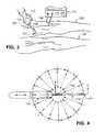
- FIG. 3is a diagrammatical view of undesired veins being removed from the legs of a patient by the surgical system of FIG. 1 ;
- FIG. 4shows a pattern of movement of the surgical instrument of the surgical system of FIG. 3 to remove undesired veins
- FIG. 5is a cross-sectional view taken about line 5 — 5 of FIG. 4 ;
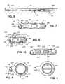
- FIG. 6is a fragmentary view of the distal end of a surgical instrument of the surgical system of FIG. 1 ;
- FIG. 7is a fragmentary view of another embodiment of the distal end of a surgical instrument of the surgical system of FIG. 1 ;
- FIG. 8is another embodiment of a distal end of a surgical instrument of the surgical system of FIG. 1 ;
- FIG. 9is a fragmentary view of another embodiment of the distal end of the surgical instrument of the surgical system of FIG. 1 ;
- FIG. 10is a fragmentary view of another embodiment of the distal end of the surgical instrument of the surgical system of FIG. 1 ;
- FIG. 11is a side elevational view of another embodiment of a surgical system to remove undesired veins in a venous system of a patient;
- FIG. 12is a cross-sectional view taken about line 12 of FIG. 11 ;
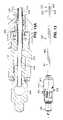
- FIG. 13shows an additional embodiment of a surgical instrument for removing undesired veins
- FIG. 13Ais a cross-sectional view of a proximal end of the surgical instrument of FIG. 13 ;
- FIG. 14illustrates a fiberoptic transilluminator
- FIG. 14Ais an end view of the fiberoptic transilluminator of FIG. 14 , taken along lines 14 A— 14 A;
- FIG. 15illustrates the placement of the fiberoptic transilluminator beneath a patient's skin
- FIG. 16illustrates an additional embodiment of a fiberoptic transilluminator
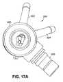
- FIG. 17shows an additional embodiment of a surgical instrument for removing undesired veins
- FIG. 17Ais an end view of the surgical instrument of FIG. 17 , taken along lines 17 A— 17 A.
- FIG. 1a preferred embodiment of a surgical system 100 to remove undesired veins in a venous system of a patient is illustrated.
- the surgical system 100allows a single surgeon to remove veins from a patient more quickly than traditional techniques.
- the undesired veinscan be completely removed with minimal scarring and without hospitalization.
- the surgical system 100can also allow two or more surgeons to remove undesired veins of a patient at the same time.
- the surgical system 100generally includes a control unit 110 and a surgical instrument 120 .
- the control unit 110sends electrical signals through a cable 112 at a selected amplitude and frequency.
- the electrical signalsenergize a motor 122 of the surgical instrument 120 which drives a cutting element 141 at a selected speed.
- the speed of the cutting element 141 of the surgical instrument 120is controlled and monitored by the control unit 110 .
- the surgical instrument 120 of the surgical system 100can be utilized by a surgeon to remove undesired veins in a leg 190 of a patient.
- a second handpiece assembly(not shown) may also be connected to the control unit 110 to allow a second surgeon to remove undesired veins in the other leg 192 or another portion of the patient. It will be recognized that any suitable number of surgical instrument 120 can be attached to the control unit 110 to remove undesired veins.
- one or more small incisions 152are made through the skin layer 194 of the patient near the undesired veins.
- the distal end of the surgical instrument 120is inserted through the small incision 152 .
- the cutting element 141is energized at a desired speed.
- the cutting element 141is then placed in contact with an undesired vein 195 of the patient as shown in FIG. 3 and 5 .
- the portion of the vein 195 that contacts the cutting element 141is cut up into small or tiny particles or pieces.
- the particles of the undesired vein 19 Sare removed from the surgical site to a suction or vacuum source 160 .
- the small incision 152can be closed with steri-strips or any suitable closure material. Although these incisions can be closed with sutures, it is considered unnecessary due to the small size of the incisions, and is also undesirable since suturing the skin can cause scarring.
- the control unit 110 of the surgical system 100preferably includes a control system (not shown) integral to the control unit 110 , an on-off switch 112 , jacks or connectors 114 and 115 , a power control switch 116 , and a display 118 .
- the control unit 110sends signals to the surgical instrument 120 to control the acceleration, deceleration, and speed of the cutting element 141 of the surgical instrument 120 .
- the control unit 110may also monitor the speed of the cutting element 141 in order to limit the speed and the torque of the cutting element 141 to within preselected limits for optimum performance of the surgical instrument 120 being used. It will be recognized that the control unit 110 may drive the cutting element 141 at any suitable speed and torque.
- the on-off switch 112 of the surgical system 100controls the electrical power to the control unit 110 to allow the surgeon to actuate the cutting element 141 of the surgical instrument 120 .
- the control unit 110provides power to drive the cutting element 141 of the surgical instrument 120 at a desired speed.
- the jack 114 of the control system 110is attached to the proximal end of the cable 112 to allow the surgical instrument 120 to be connected to the control unit 110 .
- the jack 115 of the control systemprovides another connector to allow another cable of a surgical instrument to be coupled to the control unit 110 . Although only two jacks 114 and 115 are shown, it is contemplated that any suitable number of jacks may be incorporated into the control unit 110 .
- the control unit 110also has a power line 118 for insertion in an electro-signal unit or conventional outlet. It is contemplated that the control unit 110 may also be powered by a direct current (DC) source, such as a battery.
- the control unit 110may be any suitable control unit, such as Model No. PS3500EPTM or Dyonics®EP-1 surgical drive system available from Smith & Nephew.
- the surgical instrument 120generally includes a motor drive unit or handpiece assembly 121 and a blade assembly 140 .
- the handpiece assembly 121includes a motor 122 , a suction nozzle 124 , a housing or an outer casing 125 , a trigger mechanism 126 , and a vacuum switch 128 .
- the distal end of the handpiece assembly 121is sized and configured to receive the blade assembly 140 , and proximal end of the handpiece assembly 121 is coupled to the control unit 110 by the cable 112 .
- the cable 112may include ducts or vents to allow air or a cooling fluid to be introduced into the handpiece assembly 121 to cool the motor 122 .
- a suitable handpiece assembly 121may be Model Nos. 7205354, 72-5355, or 72-5357, available from Smith & Nephew.
- the housing 125 of the handpiece assembly 121is adapted to isolate the operator from the inner components of the handpiece assembly 121 .
- the housing 125is preferably substantially cylindrically shaped and is adapted to be held by a user in a conventional manner, but may be any suitable shape or size which allows it to be grasped by the user. While a single or unitary component housing 125 is illustrated, the housing 125 may comprise multiple parts or pieces.
- the housing 125 of the handpiece assembly 121can be constructed from a plastic, titanium, aluminum, or steel. It is also contemplated that the housing 125 may be made from a variety of materials including other plastics (i.e., liquid crystal polymer (LCP), nylon, or polycarbonate) or any other suitable material.
- LCPliquid crystal polymer
- nylonnylon
- polycarbonateany other suitable material.
- the triggering mechanism 126 of the handpiece assembly 121allows a surgeon to activate the control unit 110 so that power may be continuously supplied to the motor 122 of the handpiece assembly 121 .
- the triggering mechanism 126preferably includes a switch incorporated in the handpiece assembly 121 . It will be recognized that the triggering mechanism 126 may alternatively include a foot activating switch 136 that is detachably coupled or attached to the control unit 110 by a cable or cord 138 .
- the suction nozzle 124 of the handpiece assembly 121is coupled to a vacuum source 160 by a hose 162 .
- the vacuum source 160draws a vacuum through a conduit (not shown) defined through the handpiece assembly 121 and the surgical instrument 120 .
- the vacuum source 160causes vein tissue and other fluids to be drawn from the surgical site through the conduit of the blade assembly 140 and handpiece assembly 121 into the vacuum source 160 .
- the vacuum source 160can be any suitable vacuum or suction source to remove vein tissue from the surgical site. It is also contemplated that the vacuum source 160 can be a separate tool, such as, for example, a cannula, or any other suitable instrument that can be inserted in the incision to remove vein tissue.
- the motor 122 of the handpiece assembly 121is preferably disposed within the handpiece assembly 121 .
- the motor 122receives power from the control unit 110 over wires (not shown) in cable 112 .
- the motor 122preferably includes a housing 122 a and a drive shaft 122 b. When the motor 122 is activated, the drive shaft 122 b rotates to drive the cutting element 141 of the surgical instrument 120 at a desired speed.
- the motor 122is preferably a reversible rotational drive motor that can turn the drive shaft 122 b in either direction or oscillate the shaft 122 b back and forth. It will be recognized that the motor 122 can be any suitable device that can drive or actuate the cutting element 141 of the surgical instrument 120 .
- the blade assembly 140 of the surgical instrument 120preferably includes an outer stationary member 170 and a rotatable member 180 .
- the blade assembly 140is preferably a disposable unit to eliminate resterilization of the portions of the assembly that enters into the patient's body. Therefore, the blade assembly 140 is removed from the handpiece assembly 121 after use and disposed of.
- the blade assembly 140may include any suitable blade from the EP-1 family from Smith & Nephew, such as, for example, the full radius 3.5 mm blade (Ref. No. 7295305), or any suitable blade from Xomed® Endoscopy Products.
- the distal end of the outer stationary member 170is sized for insertion into an incision of the body via a puncture opening made through the skin.
- the outer stationary member 170includes a fitting 172 and an elongated member 174 . It is contemplated that the distal end of the blade assembly 140 may be bendable or may be articulable in various directions.
- the fitting 172 of the outer stationary member 170is preferably adapted to be threaded or snapped into the distal end of the handpiece assembly 121 .
- the fitting 172is preferably constructed from a plastic material and has an aperture 173 extending therethrough. It is contemplated that the fitting 172 may be fabricated from any suitable material.
- the distal end of the fitting 174is coupled or attached to the proximal end of the elongated member 174 of the outer stationary member 170 .
- the elongated member 174 of the outer stationary member 170preferably includes an aperture 176 extending longitudinally therethrough and one or more ports or openings 178 (one being shown).
- the elongated member 174preferably has a length of about 5 inches and is fabricated from stainless steel. It is contemplated that the elongated member 174 may have any suitable length and can be manufactured from any suitable material.
- the port 178 of the elongated member 174is preferably located at or near the distal end of the elongated member 174 .
- the port 178has a generally cylindrical shape and preferably includes a pair of cutting edges 178 a and 178 b.
- the port 178allows vein tissue to enter into the aperture 176 so that the cutting element 141 of the surgical instrument 120 can sever the tissue as further described below.
- the port 178can be any size and shape to receive vein tissue.
- a guardmay also be disposed across the port 178 to limit the amount of extraneous tissue that can enter into the port 178 to be severed.
- the aperture 176 of the elongated member 174 and the aperture 173 of the fitting 172are adapted to receive the rotatable member 180 .
- the rotatable member 180preferably includes a base 182 and an elongated member 184 .
- the base 182is preferably fabricated from plastic. It will be recognized that the base 182 may be fabricated from any suitable material.
- the inner rotatable member 180is preferably rotated at various speeds by the motor 122 .
- the distal end of the base 182 of the rotatable member 180is coupled to the proximal end of the elongated member 184 , and the proximal end of the base 182 is coupled to the drive shaft 122 b of the motor 122 .
- the drive shaft 122 b of the motor 122When the drive shaft 122 b of the motor 122 is energized, the drive shaft 122 b rotates the base 182 and the elongated member 184 of the rotatable member 180 at a desired speed.
- the elongated member 184 of the rotatable member 180preferably includes an aperture 186 extending longitudinally therethrough and a cutting element 141 .
- the elongated member 184is preferably disposed coaxially within the elongated member 174 of the outer stationary member 172 .
- the elongated member 184is preferably fabricated from stainless steel. It is contemplated that the elongated member 184 may be constructed from any suitable material.
- the cutting element 141 of the elongated member 184is disposed at or near the distal end of the elongated member 184 .
- Vein tissue that is exposed to the cutting element 141 through the port 178 of the outer stationary member 170is cut by the cutting element 141 into small pieces.
- the piecesare drawn through the aperture 186 of the rotatable member 180 and through the suction nozzle 124 of the handpiece assembly 121 by the use of suction applied by the vacuum source 160 .
- the cutting element 141 of the rotatable member 180preferably includes one or more ports or openings 188 (one being shown) disposed in the outer surface of the elongated member 184 .
- the port 188has a generally cylindrical shape and preferably includes a pair of cutting edges 188 a and 188 b .
- the cutting edges 188 a and 188 b of the port 188 of the rotatable member 180are sharp and cooperate with sharpened edges 178 a and 178 b of the port 178 of the outer stationary member 170 .
- the cutting element 141may also comprise a blade, abrading burr, or ultrasonic element.
- the cutting edges 188 a and 188 b of the port 188are configured for cutting vein tissue when the rotatable member 180 is rotated in either direction of rotation, as selected by the surgeon.
- the port 188 of the rotatable member 180periodically aligns with the port 178 of the outer stationary member 170 to admit vein tissue.
- the vein tissueenters into the ports 178 and 188 , the vein tissue is severed or sheared between the cutting edges 188 a and 188 b of the rotatable member 180 and the cutting edges 178 a and 178 b of the outer stationary member 170 .
- the severed tissueis removed via the aperture 186 in the rotatable member 180 and through the suction nozzle 124 via a conduit (not shown) in the handpiece assembly 121 to the vacuum source 160 .
- the cutting element 141may include any suitable cutting implement and may be vibrated at a high rate of speed (i.e., in an ultrasonic range).
- the surgical instrumentpreferably includes an outer stationary member 210 and an inner stationary member 220 .
- the outer stationary member 220includes a fitting (not shown) and an elongated member 212 .
- the elongated member 212 of the outer stationary member 210preferably includes an aperture 214 extending longitudinally therethrough and two ports or openings 216 and 218 .
- the ports 216 of the elongated member 210are preferably located at or near the distal end of the elongated member 210 and are arranged in a row along the side of the elongated member 210 .
- the ports 216 and 218have a generally cylindrical shape and each preferably include a pair of cutting edges 230 , 232 , 234 , and 236 . It will be recognized that the ports 216 and 218 can be any size and shape to receive vein tissue.
- a guard 220is preferably disposed across the port 218 to limit the amount of vein tissue that can enter into the port 178 to be severed.
- the rotatable member 220preferably includes a base (not shown) and an elongated member 222 .
- the elongated member 222 of the rotatable member 220preferably includes an aperture 224 extending longitudinally therethrough and two cutting elements 226 and 228 .
- the elongated member 222 of the rotatable member 220is preferably disposed coaxially within the elongated member 212 of the outer stationary member 210 .
- the elongated member 222 of the rotatable member 220is preferably fabricated from stainless steel. It is contemplated that the elongated member 222 may be manufactured from any suitable material.
- the cutting elements 226 and 228 of the elongated member 222 of the rotatable member 220are disposed near the distal end of the elongated member 222 .
- the cutting elements 226 and 228 of the rotatable member 220preferably includes two ports or openings 240 and 242 disposed in the outer surface of the elongated member 222 .
- the ports 240 and 242have a generally cylindrical shape and each preferably includes a pair of cutting edges 244 , 246 , 248 , and 250 .
- the cutting edges 244 , 246 , 248 , and 250 of the ports 240 and 242are sharp and cooperate with sharpened edges of the ports 216 and 218 of the outer stationary member 210 .
- the cutting elements 226 and 228may be a blade, abrading burr, or an ultrasonic element.
- the ports 216 and 218 of the rotatable member 220periodically aligns with the ports 240 and 242 , respectively, of the outer stationary member 210 to admit vein tissue.
- the vein tissueis severed or sheared between the cutting edges 244 , 246 , 248 and 250 of the rotatable member 220 and the cutting edges 230 , 232 , 234 , and 236 of the outer stationary member 210 .
- the severed issueis removed from the surgical site by a vacuum source (not shown).
- FIG. 7a distal end of another surgical instrument 300 to remove undesired veins is illustrated which in many respects corresponds in construction and function to the previously described surgical instrument of FIG. 6 .
- Components of the surgical instrument 300which generally correspond to those components of the surgical instrument 200 of FIG. 6 are designated by like reference numerals in the three-hundred series.
- the surgical instrument 300includes another port 360 in the-outer stationary member 310 and a corresponding port 370 of the rotatable member 320 to sever vein tissue. It will be recognized that the surgical instrument 300 may include any suitable number of ports in the outer stationary member 310 and the rotatable member 320 to cut vein tissue.
- FIG. 10a distal end of another surgical instrument 500 to remove undesired veins is illustrated which in many respects corresponds in construction and function to the previously described surgical instrument 300 of FIG. 7 .
- Components of the surgical instrument 500which generally correspond to those components of the surgical instrument 300 of FIG. 5 are designated by like reference numbers in the five-hundred series.
- the surgical instrument 500includes guards 580 and 590 that extend across ports 560 and 570 of the surgical instrument 500 , and the distal port 518 is configured without a guard.
- the surgical instrument 400preferably includes an outer stationary member 410 and a rotatable member 420 .
- the outer stationary member 410includes a fitting (not shown) and an elongated member 412 .
- the elongated member 412 of the outer stationary member 410preferably includes an aperture 414 extending longitudinally therethrough and opening or port 416 .
- the port 416 of the elongated member 412is preferably located at or near the distal end of the elongated member 412 .
- the port 416has a generally round shape and preferably includes a cutting edge 418 . It will be recognized that the port 416 can be any size and shape to receive vein tissue.
- a guard 440(see FIG. 9 ) may be disposed across the port 416 to limit the amount of vein tissue that can enter into the port 416 to be severed.
- the rotatable member 420preferably includes a base (not shown) and an elongated member 422 .
- the elongated member 422 of the rotatable member 420preferably includes an aperture 424 extending longitudinally therethrough and a cutting element 426 .
- the elongated member 422 of the rotatable member 420is preferably disposed coaxially within the elongated member 412 of the outer stationary member 410 .
- the elongated member 412is preferably fabricated from stainless steel. It is contemplated that the elongated member 412 may be manufactured from any suitable material.
- the cutting element 426 of the elongated member 422is disposed at or near the distal end of the elongated member 422 .
- the cutting element 426preferably includes a port or opening 428 disposed in the outer surface of the elongated member 422 .
- the port 428has a generally substantially round shape and a cutting edge 430 disposed around the periphery of the port 428 .
- the cutting edge 430 of the port 428is sharp and cooperates with the sharpened edge of the port 416 of the outer stationary member 410 .
- the cutting element 426may comprise a blade, abrading burr, or ultrasonic element.
- the port 428 of the rotatable member 420periodically aligns with the port 416 of the outer stationary member 410 to admit vein tissue.
- the vein tissueis severed or sheared between the cutting edge 430 of the rotatable member 420 and the cutting edge 418 of the outer stationary member 410 .
- the severed tissueis removed from the surgical site by a vacuum source (not shown).
- FIG. 11another surgical system 700 is illustrated which in many respects corresponds in construction and function to the previously described surgical system 100 of FIG. 1 .
- Components of the surgical system 700which generally correspond to those components of the surgical instrument 100 are designated by like reference numbers in the seven-hundred series.
- the surgical system 700includes an irrigation assembly 800 that allows saline or other materials to be introduced into the surgical site of the patient.
- the irrigation assembly 800preferably includes an elongated member 810 and a saline bag 820 .
- the elongated member 810has an aperture extending therethrough to allow the saline to flow from the saline bag 820 through the elongated member 810 and into the handpiece assembly via a coupling member 822 when a trigger member 823 is depressed.
- the salineflows through a conduit 824 and into the surgical site.
- the coupling member 822can be located at the distal end of the handpiece assembly or near the proximal end of the elongated member. It will be recognized that the tip of the instrument can be dipped into saline to introduce the saline into the surgical site or the saline can flow through a gap formed between the outer surface of the rotatable member and the inner surface of the outer stationary member. The saline can be suctioned from the surgical site when the vacuum source is activated.
- FIGS. 3–5the operation of the surgical system to remove undesired veins, such as, varicose and spider veins, of legs of a patient will be described.
- a lower extremity venous doppleris taken of the patient to reveal the incompetent valves of the veins between the superficial vein system and the deeper vein system. If there is incompetence in the greater saphenous veins going into the femoral veins and the lesser saphenous veins going into the popliteal veins, the greater saphenous veins will be ligated and divided.
- the patientmay undergo a general anesthetic, regional anesthetic (i.e., spinal or epidural), or a local anesthetic.
- saphenous veinTo disconnect the saphenous vein, an incision is made in the groin area to ligate the saphenous vein at its juncture with the femoral vein. All branches of the saphenous vein are ligated and divided with titanium clips and the main greater saphenous vein is ligated proximally and distally.
- the saphenous veincan be disconnected from the deep veins at a lower point along the leg, such as behind the knee at the lesser saphenous-popliteal junction. This alternative technique may be advisable in circumstances in which treatment of various veins is only necessary in the lower leg.
- the saphenous veinWhen the saphenous vein is disconnected from the femoral vein, the blood from the deep veins will be prevented from flowing backing into the saphenous vein, eliminating the primary cause of the varicose veins. While blood can still enter the saphenous vein through the numerous tributary veins, the subsequent permanent closure of the saphenous vein will effectively prevent this occurrence. Once the saphenous vein is disconnected from the femoral vein, the varicose and/or spider veins can be treated. It will also be recognized that the saphenous vein may not have to be disconnected.
- the patientis placed in a trendelenburg position, i.e., feet up, and the incision site is prepared.
- a surgeonmakes a small incision 152 through the skin layer and subcutaneous tissue of the patient.
- the incisionis approximately 2–3 mm and only needs to be large enough to permit the distal end of the surgical instrument 120 to pass therethrough.
- the incision 152may be made by a blade, such as a small surgical scalpel, such as a Number 67 scalpel blade.
- the incision 152is preferably made near the center of the undesired veins to reach the most veins. It should be apparent that the selection of the incision 152 is for exemplary purposes only and the incision may be made at any suitable location.
- the distal end of the surgical instrument 120is inserted through the incision 152 made at the skin with the motor 122 of the handpiece assembly 121 . It is also contemplated that the distal end of the surgical instrument 120 may have a sharp point that enables it to be inserted through the skin layer without having to first make an incision.
- the surgical instrument 120may have a retractable scalpel blade.
- the surgeonthen activates the switch 128 to cause vacuum suction.
- the distal end of the surgical instrument 120is placed on the undesired vein in order to move the vein away from the skin and to remove as much vein tissue with the vacuum suction.
- the distal end of the surgical instrument 120is then guided underneath or on the side of the vein to be removed.
- the surgeonthen activates the switch 126 to actuate the cutting element 141 of the surgical instrument 120 at a predetermined speed.
- the surgeoncan control rotational speed and direction (either unidirectional or oscillatory) using the switch 126 on the handpiece assembly 121 or the foot switch 136 .
- the cutting element 141can rotate over a wide range of speeds, for example, approximately 500–2000 rpm, and preferably in the range of 800–1200 rpm.
- Oscillationcan be in the ultrasonic range.
- Salinecan also be introduced into the surgical site.
- the vacuum suction 160draws the vein tissue to be cut into the port 178 of the outer stationary member 170 .
- the veinis severed by the cutting element 141 of the rotary member 180 and cut into small particles.
- the surgeoncan move the surgical instrument 120 back and forth under the skin and pushing it in and out in a fan-like or circular fashion as permitted to progressively cut away the vein.
- the amount of cuttingvaries with the speed of the rotatable member 180 , the amount of pressure applied by the surgeon, the sharpness of the cutting edges, and the number and size of the ports on the outer stationary member 170 .
- the incisionis closed by conventional techniques, such as, with steri-strips. While suturing of the incision is also possible, it is considered unnecessary due to the small size of the incision, and is also undesirable since suturing the skin can cause scarring. This procedure can then be repeated at another location.
- a stockingcan be rolled up on the patient's leg and a convatec duoderm elastaplast type stocking can be placed from just proximal to the toes to the upper thigh in order for compression to take place.
- the apparatus and methods of the present inventionallow various veins to be removed with minimal scarring and without hospitalization. Moreover, the procedure can be performed on an outpatient basis without any of the usual complications of conventional surgical procedures. The procedure can be performed in a short period of time to avoid physician fatigue, minimize anesthesia time for the patient, and increase the number of procedures possible with a given operating room facility.
- surgical instrument 900includes a housing 901 with an outer stationary member 902 having a proximal hub 904 for attaching member 902 to a handpiece (not shown), and an inner member 906 rotatably received within outer member 902 .
- Inner member 906includes a proximal hub 908 driven by a motor (not shown).
- Outer member 902has a cylindrical wall 910 defining a lumen 912 in which inner member 906 is received.
- Inner member 906defines a lumen 920 through which cut tissue is aspirated, as described above.
- Hub 904 of outer member 902includes an irrigation/tumescence inlet connector 914 communicating with a port 916 which extends through outer member wall 910 permitting access of irrigation/tumescence fluid to a channel 918 defined between outer member 902 and inner member 906 .
- Distal end 922 of outer member 902includes a window 924 providing access to a cutter 926 located at a distal end 928 of inner member 906 .
- Window 924is preferably a full radius window with smooth cutting edges (such as is formed on the Smith & Nephew 4.5 mm Full Radius Resector, part no. 3443), and cutter 926 is preferably an incisor blade with serrated cutting edges (such as that formed on the Smith & nephew 4.5 mm Incisor, part no. 3810).
- This blade combinationadvantageously produces a surgical instrument for cutting veins which is more aggressive than a standard full radius blade (which has smooth cutting edges on the inner and outer members) but less aggressive than an incisor blade (the inner and outer members of which both have serrated cutting edges).
- Hub 904includes a handpiece attachment element 930 and a locator tab 932 for attaching hub 904 to a handpiece, as described in U.S. Ser. No. 08/630,537, entitled SURGICAL INSTRUMENT HANDPIECE AND SYSTEM, Incorporated by reference herein.
- the trigger mechanism 126 on the handpiece for controlling the rotation of inner member 906is aligned with window 924 such that trigger mechanism 126 is easily accessible to the surgeon during use of surgical instrument 900 (cutting window 924 generally faces the surgeon during use, as described below).
- Vacuum switch 128can be used to turn off the suction for aspiration of cut tissue such that irrigation channel 918 can be used to deliver tumescence fluid to the surgical site.
- While surgical instrument 900is shown having constant diameter inner and outer members 902 , 906 , the members can be enlarged at all but there distal ends to reduce potential clogging of cut tissue in lumen 920 with their diameters sloping to smaller diameter distal ends.
- Window 924can be elongated to provide a larger tissue entry port.
- a light sourcee.g., fiberoptic illuminating device 950
- the light sourceis positioned subcutaneously and in close proximity to the vein to be cut, e.g., about 1 to 2 cm from the vein, with light directed at the vein from below or from the side of the vein causing the vein to be shadowed. This enables the surgeon to see the vein through the patient's skin, greatly improving the accuracy, efficacy, and efficiency of the procedure, and enabling the surgeon to see even small, branching veins which can also be advantageously removed using surgical instrument 900 .
- Illuminating device 950includes a housing 951 having a handle 952 and an elongated member 954 terminating in a tip 956 .
- Housing 951contains a fiberoptic bundle 958 .
- Handle 952includes a lightpost 960 for connecting fiberoptic bundle 958 to a light transmitter (not shown).
- Lightpost 960is positioned at proximal end 962 of handle 952 substantially in the direction of a longitudinal axis, A, of illuminating device 950 such that lightpost 960 does not contact the patient during use, which would potentially interfere with the placement of illuminator tip 956 within the patient, and does not interfere with the surgeons grip on handle 952 .
- Member 954has a small outer diameter of, e.g., only about 0.165′′, to minimize tissue trauma.
- Tip 956 of illuminating device 950 or the distal end of fiberoptic bundle 958 (or both)is oriented at an oblique angle, ⁇ , to the longitudinal axis, A.
- ⁇oblique angle
- Member 954has a length, L 1 , of about 7.5′′, such that a large vascular region can be accessed from a single skin portal, and handle 952 has a length, L 2 , of about 3.75′′.
- Member 954 and handle 952are preferably made from stainless steel.
- handle 952is somewhat hourglass shaped for ease of handling by the surgeon.
- Handle 952has, e.g., a thickness, T 1 , at waist section 964 of about 0.375′′, and a larger thickness, T 2 , of about 0.5′′ nearer to its upper and lower ends.
- Sides 966 , 968 of handle 952include grooves 970 to facilitate grasping of handle 952 by the surgeon.
- the surgeonuses an ink marker to outline on the patient's skin 971 the veins to be removed.
- the surgeonplaces illuminating device 950 through a first incision in the patient's skin to a location in proximity of a vein 973 to be removed, with the light from illuminating device 950 directed generally upwardly or to the side of the vein to shadow the vein.
- illuminating device 950directs a light cone 975 upward so the surgeon can see the vein shadowed through the skin.
- the veincan also be shadowed and seen through the skin when the cone of light is directed at the vein from the side of the vein.
- the surgeonmakes a second incision in the patient's skin spaced by a few inches from the first incision with the vein to be removed located between the incisions.
- the surgeonthen places cutting instrument 900 through the second incision and locates distal end 922 of cutting instrument 900 underneath the vein and facing tip 956 of illuminating device 950 .
- the surgeonthen activates cutting instrument 900 to cut the vein.
- Illuminating device 950permits the surgeon to visualize the vein and the distal end 922 of the cutting instrument 900 through the patient's skin during cutting. Illuminating device 950 also aids the surgeon in identifying other diseased vessels, particularly small branches of veins which are otherwise difficult to see.
- Tumescenceis preferably carried out prior to cutting to shrink the vessels thus limiting blood loss and improving illumination. After cutting is completed, further tumescence can limit blood flow and speed healing. Irrigation is preferably carried out during cutting. Tumescence and irrigation fluid can be delivered through surgical instrument 900 , through the illuminating device, as described below, or through both instruments.
- an alternative fiberoptic illuminating device 950 aincludes a fiberoptic bundle 958 as shown in FIG. 14 , and a separate fluid channel 972 .
- Fluid channel 972is preferably a straight channel having an internal diameter of about 1 mm.
- Handle 952 aincludes a connector 974 for attaching an input fluid line (not shown) to handle 952 a to supply fluid to a proximal end 982 of fluid channel 972 , and a valve 976 for controlling flow of irrigation and tumescence fluid.
- the curvature in fiberoptic bundle 958 leading to lightpost 960facilitates the placement of both lightpost 960 and connector 974 at the proximal end 962 of handle 952 a.
- Connector 974has, e.g, either or both of a luer fitting 978 and a tapered hose barb 980 .
- Valve 976is spring loaded to be biased in an off position, and can be pushed for intermittent supply of fluid or locked on for continuous fluid supply.
- Channel 972has an open distal end 982 a, and can include distal side openings (not shown) to provide an alternative flow profile of irrigation and tumescence fluid.
- Member 954 ahas a small outer diameter of, e.g., only about 0.165′′, to minimize tissue trauma.
- an integral surgical illuminating device 984includes an outer cutting member 986 , an inner cutting member 986 a, and a fiberoptic bundle 985 attached to the external surface of outer cutting member 986 .
- a distal tip 987 of fiberoptic bundle 985is set at an angle relative to the longitudinal axis of device 984 of, e.g., about 0 to 90°, preferably about 45 to 70°, and positioned adjacent to the outer member window 988 to direct the light at a vein positioned above or beside outer member window 988 .
- surgical instrument 984also includes a separate line 989 attached to the external surface of outer member 986 and distally directed along the longitudinal axis of instrument 984 for delivering fluid to the surgical site.
- Tine 989can replace fluid supply channel 918 defined between the inner and outer members (described above), or line 989 can be in addition to fluid channel 918 .
- surgical instrument 984need not include line 989 and both tumescence and irrigation are conducted through channel 918 .
- Surgical instrument 984is otherwise as described above with reference to FIG. 14 .
- illuminating devices 950 , 950 a, and 984include lipoma (fatty tumor removal) and liposuction. During these procedures, the illuminating device can provide visualization of the veins in the area of surgery to aid the surgeon in avoiding the veins.
Landscapes
- Health & Medical Sciences (AREA)
- Surgery (AREA)
- Life Sciences & Earth Sciences (AREA)
- Molecular Biology (AREA)
- General Health & Medical Sciences (AREA)
- Veterinary Medicine (AREA)
- Engineering & Computer Science (AREA)
- Biomedical Technology (AREA)
- Heart & Thoracic Surgery (AREA)
- Medical Informatics (AREA)
- Nuclear Medicine, Radiotherapy & Molecular Imaging (AREA)
- Animal Behavior & Ethology (AREA)
- Public Health (AREA)
- Vascular Medicine (AREA)
- Pathology (AREA)
- Oral & Maxillofacial Surgery (AREA)
- Orthopedic Medicine & Surgery (AREA)
- Rheumatology (AREA)
- Surgical Instruments (AREA)
- External Artificial Organs (AREA)
Abstract
Description
Claims (10)
Priority Applications (2)
| Application Number | Priority Date | Filing Date | Title |
|---|---|---|---|
| US10/059,148US7018391B2 (en) | 1997-10-06 | 2002-01-31 | Methods and apparatus for removing veins |
| US11/360,595US8177800B2 (en) | 1997-10-06 | 2006-02-24 | Methods and apparatus for removing veins |
Applications Claiming Priority (4)
| Application Number | Priority Date | Filing Date | Title |
|---|---|---|---|
| US08/944,384US5893858A (en) | 1997-10-06 | 1997-10-06 | Method for removing veins |
| US28917299A | 1999-04-09 | 1999-04-09 | |
| US09/444,925US6436116B1 (en) | 1997-10-06 | 1999-11-24 | Methods and apparatus for removing veins |
| US10/059,148US7018391B2 (en) | 1997-10-06 | 2002-01-31 | Methods and apparatus for removing veins |
Related Parent Applications (1)
| Application Number | Title | Priority Date | Filing Date |
|---|---|---|---|
| US09/444,925ContinuationUS6436116B1 (en) | 1997-10-06 | 1999-11-24 | Methods and apparatus for removing veins |
Related Child Applications (1)
| Application Number | Title | Priority Date | Filing Date |
|---|---|---|---|
| US11/360,595DivisionUS8177800B2 (en) | 1997-10-06 | 2006-02-24 | Methods and apparatus for removing veins |
Publications (2)
| Publication Number | Publication Date |
|---|---|
| US20020082632A1 US20020082632A1 (en) | 2002-06-27 |
| US7018391B2true US7018391B2 (en) | 2006-03-28 |
Family
ID=23766917
Family Applications (3)
| Application Number | Title | Priority Date | Filing Date |
|---|---|---|---|
| US09/444,925Expired - Fee RelatedUS6436116B1 (en) | 1997-10-06 | 1999-11-24 | Methods and apparatus for removing veins |
| US10/059,148Expired - LifetimeUS7018391B2 (en) | 1997-10-06 | 2002-01-31 | Methods and apparatus for removing veins |
| US11/360,595Expired - Fee RelatedUS8177800B2 (en) | 1997-10-06 | 2006-02-24 | Methods and apparatus for removing veins |
Family Applications Before (1)
| Application Number | Title | Priority Date | Filing Date |
|---|---|---|---|
| US09/444,925Expired - Fee RelatedUS6436116B1 (en) | 1997-10-06 | 1999-11-24 | Methods and apparatus for removing veins |
Family Applications After (1)
| Application Number | Title | Priority Date | Filing Date |
|---|---|---|---|
| US11/360,595Expired - Fee RelatedUS8177800B2 (en) | 1997-10-06 | 2006-02-24 | Methods and apparatus for removing veins |
Country Status (7)
| Country | Link |
|---|---|
| US (3) | US6436116B1 (en) |
| EP (1) | EP1233702B1 (en) |
| JP (1) | JP4435458B2 (en) |
| AU (2) | AU1615401A (en) |
| CA (1) | CA2391917C (en) |
| DE (1) | DE60042559D1 (en) |
| WO (1) | WO2001037739A1 (en) |
Cited By (10)
| Publication number | Priority date | Publication date | Assignee | Title |
|---|---|---|---|---|
| US20030181934A1 (en)* | 2002-03-22 | 2003-09-25 | Gyrus Ent L.L.C. | Powered surgical apparatus, method of manufacturing powered surgical apparatus, and method of using powered surgical apparatus |
| US20040204735A1 (en)* | 2003-04-11 | 2004-10-14 | Shiroff Jason Alan | Subcutaneous dissection tool incorporating pharmacological agent delivery |
| US20040204728A1 (en)* | 2003-04-11 | 2004-10-14 | Paul Haefner | Ultrasonic subcutaneous dissection tool incorporating fluid delivery |
| US20050143801A1 (en)* | 2002-10-05 | 2005-06-30 | Aboul-Hosn Walid N. | Systems and methods for overcoming or preventing vascular flow restrictions |
| US20070244371A1 (en)* | 2006-04-04 | 2007-10-18 | Nguyen Hoa D | Phlebectomy illumination device and methods |
| US20100280328A1 (en)* | 2009-05-01 | 2010-11-04 | Tyco Healthcare Group, Lp | Methods and systems for illumination during phlebectomy procedures |
| WO2017007851A1 (en)* | 2015-07-06 | 2017-01-12 | Cirrus Technologies Kft | Surgical system and method of use |
| US10335189B2 (en) | 2014-12-03 | 2019-07-02 | PAVmed Inc. | Systems and methods for percutaneous division of fibrous structures |
| US12156693B2 (en) | 2020-05-27 | 2024-12-03 | PAVmed Inc. | Systems and methods for minimally-invasive division of fibrous structures |
| US12185978B2 (en) | 2015-07-06 | 2025-01-07 | Hermes Innovations, LLC | Surgical system and method of use |
Families Citing this family (199)
| Publication number | Priority date | Publication date | Assignee | Title |
|---|---|---|---|---|
| US6638238B1 (en)* | 1999-12-09 | 2003-10-28 | The Regents Of The University Of California | Liposuction cannula device and method |
| US6569163B2 (en)* | 2001-03-09 | 2003-05-27 | Quantumcor, Inc. | Wireless electrosurgical adapter unit and methods thereof |
| US6676677B2 (en)* | 2001-05-11 | 2004-01-13 | Jeffrey A. Klein | Liposuction cannula with abrading apertures |
| US11229472B2 (en) | 2001-06-12 | 2022-01-25 | Cilag Gmbh International | Modular battery powered handheld surgical instrument with multiple magnetic position sensors |
| CA2455385C (en) | 2001-06-26 | 2011-01-25 | Tyco Healthcare Group, Lp | Conduit harvesting instrument and method |
| US20030083681A1 (en)* | 2001-09-17 | 2003-05-01 | Moutafis Timothy E. | Surgical rotary abrader |
| US6527771B1 (en)* | 2001-09-28 | 2003-03-04 | Ethicon, Inc. | Surgical device for endoscopic vein harvesting |
| US7163546B2 (en) | 2001-12-21 | 2007-01-16 | Mirizzi Michael S | Method and apparatus for avulsion of varicose veins |
| EP1581115B1 (en)* | 2002-12-30 | 2009-10-14 | Roche Diagnostics GmbH | Blood acquisition suspension system |
| US7150747B1 (en) | 2003-01-22 | 2006-12-19 | Smith & Nephew, Inc. | Electrosurgical cutter |
| US20040236307A1 (en)* | 2003-05-21 | 2004-11-25 | Klein Jeffrey A. | Infiltration cannula |
| US20040236313A1 (en) | 2003-05-21 | 2004-11-25 | Klein Jeffrey A. | Infiltration cannula |
| US8105310B2 (en) | 2003-05-21 | 2012-01-31 | Klein Jeffrey A | Infiltration cannula |
| US8182501B2 (en) | 2004-02-27 | 2012-05-22 | Ethicon Endo-Surgery, Inc. | Ultrasonic surgical shears and method for sealing a blood vessel using same |
| EP1593346A1 (en)* | 2004-05-04 | 2005-11-09 | L'Echevin, Patrick | Light-emitting, linear collimated, successively readjustable,operative vein stripper |
| IL161928A (en) | 2004-05-11 | 2005-11-20 | Pikus Valery | Instrument and method for cosmetic removal of superficial varicose veins |
| EP1750589A2 (en)* | 2004-05-13 | 2007-02-14 | Medtronic, Inc. | Percutaneous vein harvester |
| WO2006007410A2 (en) | 2004-06-16 | 2006-01-19 | Medtronic, Inc. | Minimally invasive coring vein harvester |
| US20060036274A1 (en)* | 2004-06-25 | 2006-02-16 | Usher Raymond W | One-piece vessel harvester |
| US7762951B2 (en)* | 2004-06-25 | 2010-07-27 | Medtronic, Inc. | Vein harvesting system including dilator shaft and removable retractor housing |
| US20060079879A1 (en) | 2004-10-08 | 2006-04-13 | Faller Craig N | Actuation mechanism for use with an ultrasonic surgical instrument |
| US20060095056A1 (en)* | 2004-10-29 | 2006-05-04 | Peter Douglas | Device for incising a blood vessel |
| US20070191713A1 (en) | 2005-10-14 | 2007-08-16 | Eichmann Stephen E | Ultrasonic device for cutting and coagulating |
| US7621930B2 (en) | 2006-01-20 | 2009-11-24 | Ethicon Endo-Surgery, Inc. | Ultrasound medical instrument having a medical ultrasonic blade |
| US20070260229A1 (en)* | 2006-05-05 | 2007-11-08 | Luis Navarro | Method and kit for treatment of varicose veins and other superficial venous pathology |
| US7763033B2 (en)* | 2006-10-18 | 2010-07-27 | Interlace Medical, Inc. | System and methods for preventing intravasation during intrauterine procedures |
| US9392935B2 (en) | 2006-11-07 | 2016-07-19 | Hologic, Inc. | Methods for performing a medical procedure |
| GB0623369D0 (en)* | 2006-11-23 | 2007-01-03 | Shturman Leonid | Handle for a rotational atherectomy device |
| US8142461B2 (en) | 2007-03-22 | 2012-03-27 | Ethicon Endo-Surgery, Inc. | Surgical instruments |
| US8226675B2 (en) | 2007-03-22 | 2012-07-24 | Ethicon Endo-Surgery, Inc. | Surgical instruments |
| US20080234709A1 (en) | 2007-03-22 | 2008-09-25 | Houser Kevin L | Ultrasonic surgical instrument and cartilage and bone shaping blades therefor |
| US8057498B2 (en) | 2007-11-30 | 2011-11-15 | Ethicon Endo-Surgery, Inc. | Ultrasonic surgical instrument blades |
| US8911460B2 (en) | 2007-03-22 | 2014-12-16 | Ethicon Endo-Surgery, Inc. | Ultrasonic surgical instruments |
| US9259233B2 (en) | 2007-04-06 | 2016-02-16 | Hologic, Inc. | Method and device for distending a gynecological cavity |
| WO2008124650A1 (en) | 2007-04-06 | 2008-10-16 | Interlace Medical, Inc. | Method, system and device for tissue removal |
| US8951274B2 (en)* | 2007-04-06 | 2015-02-10 | Hologic, Inc. | Methods of high rate, low profile tissue removal |
| US9095366B2 (en) | 2007-04-06 | 2015-08-04 | Hologic, Inc. | Tissue cutter with differential hardness |
| US8882791B2 (en) | 2007-07-27 | 2014-11-11 | Ethicon Endo-Surgery, Inc. | Ultrasonic surgical instruments |
| US8348967B2 (en) | 2007-07-27 | 2013-01-08 | Ethicon Endo-Surgery, Inc. | Ultrasonic surgical instruments |
| US8523889B2 (en) | 2007-07-27 | 2013-09-03 | Ethicon Endo-Surgery, Inc. | Ultrasonic end effectors with increased active length |
| US8808319B2 (en) | 2007-07-27 | 2014-08-19 | Ethicon Endo-Surgery, Inc. | Surgical instruments |
| US9044261B2 (en) | 2007-07-31 | 2015-06-02 | Ethicon Endo-Surgery, Inc. | Temperature controlled ultrasonic surgical instruments |
| US8252012B2 (en) | 2007-07-31 | 2012-08-28 | Ethicon Endo-Surgery, Inc. | Ultrasonic surgical instrument with modulator |
| US8512365B2 (en) | 2007-07-31 | 2013-08-20 | Ethicon Endo-Surgery, Inc. | Surgical instruments |
| US8430898B2 (en) | 2007-07-31 | 2013-04-30 | Ethicon Endo-Surgery, Inc. | Ultrasonic surgical instruments |
| EP2217157A2 (en) | 2007-10-05 | 2010-08-18 | Ethicon Endo-Surgery, Inc. | Ergonomic surgical instruments |
| US10010339B2 (en) | 2007-11-30 | 2018-07-03 | Ethicon Llc | Ultrasonic surgical blades |
| WO2009124170A1 (en)* | 2008-04-04 | 2009-10-08 | The Cleveland Clinic Foundation | Use of epineural sheath grafts for neural regeneration and protection |
| US9089360B2 (en) | 2008-08-06 | 2015-07-28 | Ethicon Endo-Surgery, Inc. | Devices and techniques for cutting and coagulating tissue |
| US8058771B2 (en) | 2008-08-06 | 2011-11-15 | Ethicon Endo-Surgery, Inc. | Ultrasonic device for cutting and coagulating with stepped output |
| US10080578B2 (en)* | 2008-12-16 | 2018-09-25 | Nico Corporation | Tissue removal device with adjustable delivery sleeve for neurosurgical and spinal surgery applications |
| US11903602B2 (en) | 2009-04-29 | 2024-02-20 | Hologic, Inc. | Uterine fibroid tissue removal device |
| US9700339B2 (en) | 2009-05-20 | 2017-07-11 | Ethicon Endo-Surgery, Inc. | Coupling arrangements and methods for attaching tools to ultrasonic surgical instruments |
| US8650728B2 (en) | 2009-06-24 | 2014-02-18 | Ethicon Endo-Surgery, Inc. | Method of assembling a transducer for a surgical instrument |
| US8461744B2 (en) | 2009-07-15 | 2013-06-11 | Ethicon Endo-Surgery, Inc. | Rotating transducer mount for ultrasonic surgical instruments |
| US8663220B2 (en) | 2009-07-15 | 2014-03-04 | Ethicon Endo-Surgery, Inc. | Ultrasonic surgical instruments |
| US9017326B2 (en) | 2009-07-15 | 2015-04-28 | Ethicon Endo-Surgery, Inc. | Impedance monitoring apparatus, system, and method for ultrasonic surgical instruments |
| US9050093B2 (en) | 2009-10-09 | 2015-06-09 | Ethicon Endo-Surgery, Inc. | Surgical generator for ultrasonic and electrosurgical devices |
| US11090104B2 (en) | 2009-10-09 | 2021-08-17 | Cilag Gmbh International | Surgical generator for ultrasonic and electrosurgical devices |
| US9168054B2 (en) | 2009-10-09 | 2015-10-27 | Ethicon Endo-Surgery, Inc. | Surgical generator for ultrasonic and electrosurgical devices |
| US10441345B2 (en) | 2009-10-09 | 2019-10-15 | Ethicon Llc | Surgical generator for ultrasonic and electrosurgical devices |
| USRE47996E1 (en) | 2009-10-09 | 2020-05-19 | Ethicon Llc | Surgical generator for ultrasonic and electrosurgical devices |
| US8292805B2 (en) | 2009-11-10 | 2012-10-23 | Invuity, Inc. | Illuminated suction apparatus |
| US8957060B2 (en) | 2009-11-30 | 2015-02-17 | Jeffrey Alan KLEIN | Tumescent antibiotic solution |
| US20110172688A1 (en)* | 2010-01-11 | 2011-07-14 | Tyco Healthcare Group Lp | Conduit Harvesting Instrument and Method |
| US8961547B2 (en) | 2010-02-11 | 2015-02-24 | Ethicon Endo-Surgery, Inc. | Ultrasonic surgical instruments with moving cutting implement |
| US8469981B2 (en) | 2010-02-11 | 2013-06-25 | Ethicon Endo-Surgery, Inc. | Rotatable cutting implement arrangements for ultrasonic surgical instruments |
| US9259234B2 (en)* | 2010-02-11 | 2016-02-16 | Ethicon Endo-Surgery, Llc | Ultrasonic surgical instruments with rotatable blade and hollow sheath arrangements |
| US8323302B2 (en) | 2010-02-11 | 2012-12-04 | Ethicon Endo-Surgery, Inc. | Methods of using ultrasonically powered surgical instruments with rotatable cutting implements |
| US8579928B2 (en) | 2010-02-11 | 2013-11-12 | Ethicon Endo-Surgery, Inc. | Outer sheath and blade arrangements for ultrasonic surgical instruments |
| US8382782B2 (en) | 2010-02-11 | 2013-02-26 | Ethicon Endo-Surgery, Inc. | Ultrasonic surgical instruments with partially rotating blade and fixed pad arrangement |
| US8951272B2 (en) | 2010-02-11 | 2015-02-10 | Ethicon Endo-Surgery, Inc. | Seal arrangements for ultrasonically powered surgical instruments |
| US8486096B2 (en) | 2010-02-11 | 2013-07-16 | Ethicon Endo-Surgery, Inc. | Dual purpose surgical instrument for cutting and coagulating tissue |
| US8419759B2 (en) | 2010-02-11 | 2013-04-16 | Ethicon Endo-Surgery, Inc. | Ultrasonic surgical instrument with comb-like tissue trimming device |
| US8531064B2 (en) | 2010-02-11 | 2013-09-10 | Ethicon Endo-Surgery, Inc. | Ultrasonically powered surgical instruments with rotating cutting implement |
| GB2480498A (en) | 2010-05-21 | 2011-11-23 | Ethicon Endo Surgery Inc | Medical device comprising RF circuitry |
| US8795327B2 (en) | 2010-07-22 | 2014-08-05 | Ethicon Endo-Surgery, Inc. | Electrosurgical instrument with separate closure and cutting members |
| US9192431B2 (en) | 2010-07-23 | 2015-11-24 | Ethicon Endo-Surgery, Inc. | Electrosurgical cutting and sealing instrument |
| FR2964552B1 (en)* | 2010-09-14 | 2012-10-05 | Ct Hospitalier Universitaire Nimes | PROBE FOR SUB-CUTANE DRAINAGE DURING EVEINAGE |
| US9913577B2 (en) | 2010-09-28 | 2018-03-13 | Obp Medical Corporation | Speculum |
| US9259265B2 (en) | 2011-07-22 | 2016-02-16 | Ethicon Endo-Surgery, Llc | Surgical instruments for tensioning tissue |
| US9066678B2 (en)* | 2011-09-23 | 2015-06-30 | Alcon Research, Ltd. | Ophthalmic endoilluminators with directed light |
| WO2013119545A1 (en) | 2012-02-10 | 2013-08-15 | Ethicon-Endo Surgery, Inc. | Robotically controlled surgical instrument |
| US9237921B2 (en) | 2012-04-09 | 2016-01-19 | Ethicon Endo-Surgery, Inc. | Devices and techniques for cutting and coagulating tissue |
| US9439668B2 (en) | 2012-04-09 | 2016-09-13 | Ethicon Endo-Surgery, Llc | Switch arrangements for ultrasonic surgical instruments |
| US9226766B2 (en) | 2012-04-09 | 2016-01-05 | Ethicon Endo-Surgery, Inc. | Serial communication protocol for medical device |
| US9241731B2 (en) | 2012-04-09 | 2016-01-26 | Ethicon Endo-Surgery, Inc. | Rotatable electrical connection for ultrasonic surgical instruments |
| US9724118B2 (en) | 2012-04-09 | 2017-08-08 | Ethicon Endo-Surgery, Llc | Techniques for cutting and coagulating tissue for ultrasonic surgical instruments |
| US20150080878A1 (en)* | 2012-04-13 | 2015-03-19 | Board Of Regents, The University Of Texas System | Device and method for tissue removal |
| US20140005705A1 (en) | 2012-06-29 | 2014-01-02 | Ethicon Endo-Surgery, Inc. | Surgical instruments with articulating shafts |
| US9198714B2 (en) | 2012-06-29 | 2015-12-01 | Ethicon Endo-Surgery, Inc. | Haptic feedback devices for surgical robot |
| US9351754B2 (en) | 2012-06-29 | 2016-05-31 | Ethicon Endo-Surgery, Llc | Ultrasonic surgical instruments with distally positioned jaw assemblies |
| US9393037B2 (en) | 2012-06-29 | 2016-07-19 | Ethicon Endo-Surgery, Llc | Surgical instruments with articulating shafts |
| US9820768B2 (en) | 2012-06-29 | 2017-11-21 | Ethicon Llc | Ultrasonic surgical instruments with control mechanisms |
| US20140005702A1 (en) | 2012-06-29 | 2014-01-02 | Ethicon Endo-Surgery, Inc. | Ultrasonic surgical instruments with distally positioned transducers |
| US9226767B2 (en) | 2012-06-29 | 2016-01-05 | Ethicon Endo-Surgery, Inc. | Closed feedback control for electrosurgical device |
| US9326788B2 (en) | 2012-06-29 | 2016-05-03 | Ethicon Endo-Surgery, Llc | Lockout mechanism for use with robotic electrosurgical device |
| US9283045B2 (en) | 2012-06-29 | 2016-03-15 | Ethicon Endo-Surgery, Llc | Surgical instruments with fluid management system |
| US9408622B2 (en) | 2012-06-29 | 2016-08-09 | Ethicon Endo-Surgery, Llc | Surgical instruments with articulating shafts |
| EP2900158B1 (en) | 2012-09-28 | 2020-04-15 | Ethicon LLC | Multi-function bi-polar forceps |
| US10201365B2 (en) | 2012-10-22 | 2019-02-12 | Ethicon Llc | Surgeon feedback sensing and display methods |
| US9095367B2 (en) | 2012-10-22 | 2015-08-04 | Ethicon Endo-Surgery, Inc. | Flexible harmonic waveguides/blades for surgical instruments |
| US20140135804A1 (en) | 2012-11-15 | 2014-05-15 | Ethicon Endo-Surgery, Inc. | Ultrasonic and electrosurgical devices |
| RU2524305C1 (en)* | 2012-11-30 | 2014-07-27 | Государственное бюджетное учреждение здравоохранения города Москвы "Городская клиническая больница N 79 Департамента здравоохранения г.Москвы" | Method for modified video-assisted treatment of perianal fistulas |
| US10226273B2 (en) | 2013-03-14 | 2019-03-12 | Ethicon Llc | Mechanical fasteners for use with surgical energy devices |
| US9241728B2 (en) | 2013-03-15 | 2016-01-26 | Ethicon Endo-Surgery, Inc. | Surgical instrument with multiple clamping mechanisms |
| EP2829222B1 (en) | 2013-07-24 | 2020-05-27 | Cook Medical Technologies LLC | Locating device |
| US9814514B2 (en) | 2013-09-13 | 2017-11-14 | Ethicon Llc | Electrosurgical (RF) medical instruments for cutting and coagulating tissue |
| US9265926B2 (en) | 2013-11-08 | 2016-02-23 | Ethicon Endo-Surgery, Llc | Electrosurgical devices |
| GB2521229A (en) | 2013-12-16 | 2015-06-17 | Ethicon Endo Surgery Inc | Medical device |
| GB2521228A (en) | 2013-12-16 | 2015-06-17 | Ethicon Endo Surgery Inc | Medical device |
| US9795436B2 (en) | 2014-01-07 | 2017-10-24 | Ethicon Llc | Harvesting energy from a surgical generator |
| US9554854B2 (en) | 2014-03-18 | 2017-01-31 | Ethicon Endo-Surgery, Llc | Detecting short circuits in electrosurgical medical devices |
| US10092310B2 (en) | 2014-03-27 | 2018-10-09 | Ethicon Llc | Electrosurgical devices |
| US10463421B2 (en) | 2014-03-27 | 2019-11-05 | Ethicon Llc | Two stage trigger, clamp and cut bipolar vessel sealer |
| US9737355B2 (en) | 2014-03-31 | 2017-08-22 | Ethicon Llc | Controlling impedance rise in electrosurgical medical devices |
| US9913680B2 (en) | 2014-04-15 | 2018-03-13 | Ethicon Llc | Software algorithms for electrosurgical instruments |
| US10285724B2 (en) | 2014-07-31 | 2019-05-14 | Ethicon Llc | Actuation mechanisms and load adjustment assemblies for surgical instruments |
| US10646210B2 (en) | 2014-10-14 | 2020-05-12 | Covidien Lp | Methods and devices for vein harvesting |
| US10575835B2 (en) | 2014-10-14 | 2020-03-03 | Covidien Lp | Methods and devices for vein harvesting |
| US10639092B2 (en) | 2014-12-08 | 2020-05-05 | Ethicon Llc | Electrode configurations for surgical instruments |
| US9867602B2 (en) | 2015-02-05 | 2018-01-16 | Obp Medical Corporation | Illuminated surgical retractor |
| US10420538B2 (en) | 2015-02-05 | 2019-09-24 | Obp Medical Corporation | Illuminated surgical retractor |
| US10245095B2 (en) | 2015-02-06 | 2019-04-02 | Ethicon Llc | Electrosurgical instrument with rotation and articulation mechanisms |
| US10321950B2 (en) | 2015-03-17 | 2019-06-18 | Ethicon Llc | Managing tissue treatment |
| US10342602B2 (en) | 2015-03-17 | 2019-07-09 | Ethicon Llc | Managing tissue treatment |
| US10595929B2 (en) | 2015-03-24 | 2020-03-24 | Ethicon Llc | Surgical instruments with firing system overload protection mechanisms |
| US10939899B2 (en) | 2015-06-03 | 2021-03-09 | Obp Medical Corporation | End cap assembly for retractor and other medical devices |
| US10881387B2 (en) | 2015-06-03 | 2021-01-05 | Obp Medical Corporation | Retractor |
| ES2968069T3 (en) | 2015-06-03 | 2024-05-07 | Obp Surgical Corp | Retractor |
| US10034684B2 (en) | 2015-06-15 | 2018-07-31 | Ethicon Llc | Apparatus and method for dissecting and coagulating tissue |
| US11020140B2 (en) | 2015-06-17 | 2021-06-01 | Cilag Gmbh International | Ultrasonic surgical blade for use with ultrasonic surgical instruments |
| US10357303B2 (en) | 2015-06-30 | 2019-07-23 | Ethicon Llc | Translatable outer tube for sealing using shielded lap chole dissector |
| US11129669B2 (en) | 2015-06-30 | 2021-09-28 | Cilag Gmbh International | Surgical system with user adaptable techniques based on tissue type |
| US10034704B2 (en) | 2015-06-30 | 2018-07-31 | Ethicon Llc | Surgical instrument with user adaptable algorithms |
| US11051873B2 (en) | 2015-06-30 | 2021-07-06 | Cilag Gmbh International | Surgical system with user adaptable techniques employing multiple energy modalities based on tissue parameters |
| US11141213B2 (en) | 2015-06-30 | 2021-10-12 | Cilag Gmbh International | Surgical instrument with user adaptable techniques |
| US10898256B2 (en) | 2015-06-30 | 2021-01-26 | Ethicon Llc | Surgical system with user adaptable techniques based on tissue impedance |
| US10154852B2 (en) | 2015-07-01 | 2018-12-18 | Ethicon Llc | Ultrasonic surgical blade with improved cutting and coagulation features |
| US10064611B2 (en) | 2015-07-22 | 2018-09-04 | Covidien Lp | Methods and devices for vein harvesting |
| US10194973B2 (en) | 2015-09-30 | 2019-02-05 | Ethicon Llc | Generator for digitally generating electrical signal waveforms for electrosurgical and ultrasonic surgical instruments |
| US10595930B2 (en) | 2015-10-16 | 2020-03-24 | Ethicon Llc | Electrode wiping surgical device |
| US10179022B2 (en) | 2015-12-30 | 2019-01-15 | Ethicon Llc | Jaw position impedance limiter for electrosurgical instrument |
| US10575892B2 (en) | 2015-12-31 | 2020-03-03 | Ethicon Llc | Adapter for electrical surgical instruments |
| US10716615B2 (en) | 2016-01-15 | 2020-07-21 | Ethicon Llc | Modular battery powered handheld surgical instrument with curved end effectors having asymmetric engagement between jaw and blade |
| US11129670B2 (en) | 2016-01-15 | 2021-09-28 | Cilag Gmbh International | Modular battery powered handheld surgical instrument with selective application of energy based on button displacement, intensity, or local tissue characterization |
| US11051840B2 (en) | 2016-01-15 | 2021-07-06 | Ethicon Llc | Modular battery powered handheld surgical instrument with reusable asymmetric handle housing |
| US12193698B2 (en) | 2016-01-15 | 2025-01-14 | Cilag Gmbh International | Method for self-diagnosing operation of a control switch in a surgical instrument system |
| US11229471B2 (en) | 2016-01-15 | 2022-01-25 | Cilag Gmbh International | Modular battery powered handheld surgical instrument with selective application of energy based on tissue characterization |
| US10555769B2 (en) | 2016-02-22 | 2020-02-11 | Ethicon Llc | Flexible circuits for electrosurgical instrument |
| US10485607B2 (en) | 2016-04-29 | 2019-11-26 | Ethicon Llc | Jaw structure with distal closure for electrosurgical instruments |
| US10646269B2 (en) | 2016-04-29 | 2020-05-12 | Ethicon Llc | Non-linear jaw gap for electrosurgical instruments |
| US10702329B2 (en) | 2016-04-29 | 2020-07-07 | Ethicon Llc | Jaw structure with distal post for electrosurgical instruments |
| US10456193B2 (en) | 2016-05-03 | 2019-10-29 | Ethicon Llc | Medical device with a bilateral jaw configuration for nerve stimulation |
| US10722621B2 (en) | 2016-07-11 | 2020-07-28 | Obp Medical Corporation | Illuminated suction device |
| US10245064B2 (en) | 2016-07-12 | 2019-04-02 | Ethicon Llc | Ultrasonic surgical instrument with piezoelectric central lumen transducer |
| US10893883B2 (en) | 2016-07-13 | 2021-01-19 | Ethicon Llc | Ultrasonic assembly for use with ultrasonic surgical instruments |
| US10842522B2 (en) | 2016-07-15 | 2020-11-24 | Ethicon Llc | Ultrasonic surgical instruments having offset blades |
| US10376305B2 (en) | 2016-08-05 | 2019-08-13 | Ethicon Llc | Methods and systems for advanced harmonic energy |
| US10285723B2 (en) | 2016-08-09 | 2019-05-14 | Ethicon Llc | Ultrasonic surgical blade with improved heel portion |
| USD847990S1 (en) | 2016-08-16 | 2019-05-07 | Ethicon Llc | Surgical instrument |
| US10952759B2 (en) | 2016-08-25 | 2021-03-23 | Ethicon Llc | Tissue loading of a surgical instrument |
| US10736649B2 (en) | 2016-08-25 | 2020-08-11 | Ethicon Llc | Electrical and thermal connections for ultrasonic transducer |
| US10603064B2 (en) | 2016-11-28 | 2020-03-31 | Ethicon Llc | Ultrasonic transducer |
| US11266430B2 (en) | 2016-11-29 | 2022-03-08 | Cilag Gmbh International | End effector control and calibration |
| US10820920B2 (en) | 2017-07-05 | 2020-11-03 | Ethicon Llc | Reusable ultrasonic medical devices and methods of their use |
| US10687793B2 (en) | 2017-07-18 | 2020-06-23 | Obp Medical Corporation | Minimally invasive no touch (MINT) procedure for harvesting the great saphenous vein (GSV) and venous hydrodissector and retractor for use during the MINT procedure |
| US10278572B1 (en) | 2017-10-19 | 2019-05-07 | Obp Medical Corporation | Speculum |
| US10799229B2 (en) | 2018-02-20 | 2020-10-13 | Obp Medical Corporation | Illuminated medical devices |
| US11547466B2 (en) | 2018-06-20 | 2023-01-10 | Covidien Lp | Visualization devices and methods for use in surgical procedures |
| US20210196357A1 (en) | 2019-12-30 | 2021-07-01 | Ethicon Llc | Electrosurgical instrument with asynchronous energizing electrodes |
| US11911063B2 (en) | 2019-12-30 | 2024-02-27 | Cilag Gmbh International | Techniques for detecting ultrasonic blade to electrode contact and reducing power to ultrasonic blade |
| US12023086B2 (en) | 2019-12-30 | 2024-07-02 | Cilag Gmbh International | Electrosurgical instrument for delivering blended energy modalities to tissue |
| US11696776B2 (en) | 2019-12-30 | 2023-07-11 | Cilag Gmbh International | Articulatable surgical instrument |
| US11452525B2 (en) | 2019-12-30 | 2022-09-27 | Cilag Gmbh International | Surgical instrument comprising an adjustment system |
| US12343063B2 (en) | 2019-12-30 | 2025-07-01 | Cilag Gmbh International | Multi-layer clamp arm pad for enhanced versatility and performance of a surgical device |
| US11684412B2 (en) | 2019-12-30 | 2023-06-27 | Cilag Gmbh International | Surgical instrument with rotatable and articulatable surgical end effector |
| US11779329B2 (en) | 2019-12-30 | 2023-10-10 | Cilag Gmbh International | Surgical instrument comprising a flex circuit including a sensor system |
| US11660089B2 (en) | 2019-12-30 | 2023-05-30 | Cilag Gmbh International | Surgical instrument comprising a sensing system |
| US11786291B2 (en) | 2019-12-30 | 2023-10-17 | Cilag Gmbh International | Deflectable support of RF energy electrode with respect to opposing ultrasonic blade |
| US11950797B2 (en) | 2019-12-30 | 2024-04-09 | Cilag Gmbh International | Deflectable electrode with higher distal bias relative to proximal bias |
| US12114912B2 (en) | 2019-12-30 | 2024-10-15 | Cilag Gmbh International | Non-biased deflectable electrode to minimize contact between ultrasonic blade and electrode |
| US12053224B2 (en) | 2019-12-30 | 2024-08-06 | Cilag Gmbh International | Variation in electrode parameters and deflectable electrode to modify energy density and tissue interaction |
| US12076006B2 (en) | 2019-12-30 | 2024-09-03 | Cilag Gmbh International | Surgical instrument comprising an orientation detection system |
| US11937863B2 (en) | 2019-12-30 | 2024-03-26 | Cilag Gmbh International | Deflectable electrode with variable compression bias along the length of the deflectable electrode |
| US12336747B2 (en) | 2019-12-30 | 2025-06-24 | Cilag Gmbh International | Method of operating a combination ultrasonic / bipolar RF surgical device with a combination energy modality end-effector |
| US11944366B2 (en) | 2019-12-30 | 2024-04-02 | Cilag Gmbh International | Asymmetric segmented ultrasonic support pad for cooperative engagement with a movable RF electrode |
| US11937866B2 (en) | 2019-12-30 | 2024-03-26 | Cilag Gmbh International | Method for an electrosurgical procedure |
| US11986201B2 (en) | 2019-12-30 | 2024-05-21 | Cilag Gmbh International | Method for operating a surgical instrument |
| US11786294B2 (en) | 2019-12-30 | 2023-10-17 | Cilag Gmbh International | Control program for modular combination energy device |
| US20210196362A1 (en) | 2019-12-30 | 2021-07-01 | Ethicon Llc | Electrosurgical end effectors with thermally insulative and thermally conductive portions |
| US12064109B2 (en) | 2019-12-30 | 2024-08-20 | Cilag Gmbh International | Surgical instrument comprising a feedback control circuit |
| US11779387B2 (en) | 2019-12-30 | 2023-10-10 | Cilag Gmbh International | Clamp arm jaw to minimize tissue sticking and improve tissue control |
| US12262937B2 (en) | 2019-12-30 | 2025-04-01 | Cilag Gmbh International | User interface for surgical instrument with combination energy modality end-effector |
| US11812957B2 (en) | 2019-12-30 | 2023-11-14 | Cilag Gmbh International | Surgical instrument comprising a signal interference resolution system |
| US12082808B2 (en) | 2019-12-30 | 2024-09-10 | Cilag Gmbh International | Surgical instrument comprising a control system responsive to software configurations |
| US10959609B1 (en) | 2020-01-31 | 2021-03-30 | Obp Medical Corporation | Illuminated suction device |
| US10966702B1 (en) | 2020-02-25 | 2021-04-06 | Obp Medical Corporation | Illuminated dual-blade retractor |
| US12318080B2 (en) | 2023-07-21 | 2025-06-03 | Coopersurgical, Inc. | Illuminated surgical retractor capable of hand-held operation and of being mounted to a fixed frame |
Citations (59)
| Publication number | Priority date | Publication date | Assignee | Title |
|---|---|---|---|---|
| US3590232A (en) | 1968-03-27 | 1971-06-29 | Radioptics Inc | Annular illuminator for dental tools or the like |
| US3945375A (en) | 1972-04-04 | 1976-03-23 | Surgical Design Corporation | Rotatable surgical instrument |
| US4126136A (en) | 1976-02-09 | 1978-11-21 | Research Corporation | Photocoagulating scalpel system |
| US4249533A (en) | 1977-05-16 | 1981-02-10 | Olympus Optical Co., Ltd. | Laser knife |
| US4311138A (en) | 1980-03-10 | 1982-01-19 | Sugarman Edward D | Illuminated hypodermic needle |
| US4313431A (en) | 1978-12-06 | 1982-02-02 | Messerschmitt-Boelkow-Blohm Gesellschaft Mit Beschraenkter Haftung | Endoscopic apparatus with a laser light conductor |
| US4499899A (en) | 1983-01-21 | 1985-02-19 | Brimfield Precision, Inc. | Fiber-optic illuminated microsurgical scissors |
| US4562838A (en) | 1981-01-23 | 1986-01-07 | Walker William S | Electrosurgery instrument |
| US4693244A (en) | 1984-05-22 | 1987-09-15 | Surgical Laser Technologies, Inc. | Medical and surgical laser probe I |
| DE3603782A1 (en) | 1986-02-06 | 1987-10-15 | Hauer Gerald | Method of localising a vein stripper probe and a device for performing the method |
| US4793346A (en) | 1986-09-04 | 1988-12-27 | Bruce Mindich | Process and apparatus for harvesting vein |
| US4811734A (en) | 1987-08-13 | 1989-03-14 | Baxter Travenol Laboratories, Inc. | Surgical cutting instrument |
| US4850354A (en) | 1987-08-13 | 1989-07-25 | Baxter Travenol Laboratories, Inc. | Surgical cutting instrument |
| WO1989007913A1 (en) | 1988-03-05 | 1989-09-08 | Loertscher Jean Jacques | Tendon stripper |
| US4867157A (en) | 1987-08-13 | 1989-09-19 | Baxter Travenol Laboratories, Inc. | Surgical cutting instrument |
| US4895145A (en) | 1985-05-28 | 1990-01-23 | Surgical Laser Technologies, Inc. | Two-piece disposable laser delivery system |
| US4896015A (en) | 1988-07-29 | 1990-01-23 | Refractive Laser Research & Development Program, Ltd. | Laser delivery system |
| US4944738A (en) | 1987-10-13 | 1990-07-31 | Rodriguez Michael A | Surgical laser backstop instrument |
| US4976710A (en) | 1987-01-28 | 1990-12-11 | Mackin Robert A | Working well balloon method |
| US5011483A (en) | 1989-06-26 | 1991-04-30 | Dennis Sleister | Combined electrosurgery and laser beam delivery device |
| US5029573A (en) | 1990-03-30 | 1991-07-09 | Chow James C | System for endoscopic surgery |
| US5061266A (en) | 1988-03-30 | 1991-10-29 | Hakky Said I | Laser resectoscope and method |
| US5084052A (en) | 1989-02-09 | 1992-01-28 | Baxter International Inc. | Surgical cutting instrument with plurality of openings |
| US5084043A (en) | 1990-01-12 | 1992-01-28 | Laserscope | Method for performing a percutaneous diskectomy using a laser |
| US5085657A (en) | 1983-03-14 | 1992-02-04 | Ben Simhon Haim | Electrosurgical instrument |
| US5102410A (en) | 1990-02-26 | 1992-04-07 | Dressel Thomas D | Soft tissue cutting aspiration device and method |
| US5147354A (en) | 1988-08-19 | 1992-09-15 | Coherent, Inc. | Mid-infrared laser endoscope |
| US5156604A (en) | 1990-10-25 | 1992-10-20 | Messerschmitt-Bolkow-Blohm Gmbh | Small probing hook for arthroscopy |
| US5188634A (en) | 1990-07-13 | 1993-02-23 | Trimedyne, Inc. | Rotatable laser probe with beveled tip |
| US5203353A (en) | 1989-10-24 | 1993-04-20 | Surgical Technologies, Inc. | Method of penetrating and working in the vitreous humor of the eye |
| US5224944A (en) | 1991-01-07 | 1993-07-06 | Elliott Martin P | Aspiration tip for a cautery handpiece |
| US5254115A (en) | 1990-10-11 | 1993-10-19 | The General Hospital Corporation | Coagulating scalpels |
| US5257989A (en) | 1990-02-07 | 1993-11-02 | Coherent, Inc. | Contact laser delivery probe |
| USRE34556E (en) | 1985-01-23 | 1994-03-01 | Smith & Nephew Dyonics Inc. | Surgical system for powered instruments |
| US5312399A (en) | 1992-09-29 | 1994-05-17 | Hakky Said I | Laser resectoscope with mechanical cutting means and laser coagulating means |
| US5313962A (en) | 1991-10-18 | 1994-05-24 | Obenchain Theodore G | Method of performing laparoscopic lumbar discectomy |
| US5320617A (en) | 1993-06-25 | 1994-06-14 | Leach Gary E | Method of laser-assisted prostatectomy and apparatus for carrying out the method |
| US5342358A (en) | 1993-01-12 | 1994-08-30 | S.L.T. Japan Co., Ltd. | Apparatus for operation by laser energy |
| US5373840A (en) | 1992-10-02 | 1994-12-20 | Knighton; David R. | Endoscope and method for vein removal |
| US5409483A (en) | 1993-01-22 | 1995-04-25 | Jeffrey H. Reese | Direct visualization surgical probe |
| US5447493A (en) | 1994-01-10 | 1995-09-05 | Very Inventive Physicians, Inc. | Tumescent lipoplastic apparatus |
| US5531739A (en) | 1994-09-23 | 1996-07-02 | Coherent, Inc. | Method of treating veins |
| US5571098A (en) | 1994-11-01 | 1996-11-05 | The General Hospital Corporation | Laser surgical devices |
| US5588952A (en) | 1993-08-02 | 1996-12-31 | Dandolu; Bhaktavathsala R. | Intracardiac illuminator with suction |
| US5611357A (en) | 1995-02-09 | 1997-03-18 | Suval; William D. | Method and apparatus for treating varicose veins |
| US5611358A (en) | 1995-09-08 | 1997-03-18 | Suval; William D. | Method and apparatus for treating varicose veins |
| US5665101A (en) | 1996-04-01 | 1997-09-09 | Linvatec Corporation | Endoscopic or open lipectomy instrument |
| US5667480A (en) | 1995-10-20 | 1997-09-16 | Ethicon Endo-Surgery, Inc. | Method and devices for endoscopic vessel harvesting |
| US5782795A (en) | 1995-06-30 | 1998-07-21 | Xomed Surgical Products, Inc. | Surgical suction cutting instrument with internal irrigation |
| US5792168A (en) | 1996-11-14 | 1998-08-11 | Suval; William D. | Apparatus for treating varicose veins |
| US5810806A (en) | 1996-08-29 | 1998-09-22 | Ethicon Endo-Surgery | Methods and devices for collection of soft tissue |
| US5893858A (en) | 1997-10-06 | 1999-04-13 | Smith & Nephew, Inc. | Method for removing veins |
| US5902315A (en) | 1997-08-28 | 1999-05-11 | Ethicon Endo-Surgery, Inc. | Optical tissue dissector/retractor |
| US5913857A (en) | 1996-08-29 | 1999-06-22 | Ethicon End0-Surgery, Inc. | Methods and devices for collection of soft tissue |
| US5922004A (en) | 1997-08-28 | 1999-07-13 | Ethicon Endo-Surgery, Inc. | Method for performing optical tissue dissection/retraction |
| US6013073A (en) | 1995-05-22 | 2000-01-11 | Mxm | Instrument intended to the location of veins by means of optical fibers and to the simultaneous ablation thereof |
| US6129661A (en) | 1998-04-09 | 2000-10-10 | Smith & Nephew, Inc. | Endoscopic instrumentation with working channel |
| US6193653B1 (en) | 1998-02-06 | 2001-02-27 | Ethicon Endo-Surgery, Inc. | Methods and devices for visualizing, dissecting and harvesting vessels and the like |
| US6206823B1 (en) | 1999-08-02 | 2001-03-27 | Ethicon Endo-Surgery, Inc. | Surgical instrument and method for endoscopic tissue dissection |
Family Cites Families (8)
| Publication number | Priority date | Publication date | Assignee | Title |
|---|---|---|---|---|
| US34556A (en)* | 1862-03-04 | Improvement in steam-boilers | ||
| JPS5139348B1 (en)* | 1970-12-09 | 1976-10-27 | ||
| US5161266A (en)* | 1991-08-06 | 1992-11-10 | Hildebrand Gerald R | Portable shower |
| US5456689A (en)* | 1993-10-13 | 1995-10-10 | Arnold J. Kresch | Method and device for tissue resection |
| PH31381A (en)* | 1994-02-07 | 1998-10-29 | Isk Biotech Corp | Pesticidal micronutrient compositions containing zinc oxide. |
| US5601589A (en)* | 1994-06-29 | 1997-02-11 | General Surgical Innovations, Inc. | Extraluminal balloon dissection apparatus and method |
| US5601583A (en)* | 1995-02-15 | 1997-02-11 | Smith & Nephew Endoscopy Inc. | Surgical instrument |
| US5871493A (en) | 1995-10-31 | 1999-02-16 | Smith & Nephew Endoscopy Inc. | Surgical instrument handpiece and system |
- 1999
- 1999-11-24USUS09/444,925patent/US6436116B1/ennot_activeExpired - Fee Related
- 2000
- 2000-11-16EPEP00978724Apatent/EP1233702B1/ennot_activeExpired - Lifetime
- 2000-11-16JPJP2001539357Apatent/JP4435458B2/ennot_activeExpired - Fee Related
- 2000-11-16AUAU16154/01Apatent/AU1615401A/ennot_activeAbandoned
- 2000-11-16WOPCT/US2000/031504patent/WO2001037739A1/enactiveApplication Filing
- 2000-11-16CACA2391917Apatent/CA2391917C/ennot_activeExpired - Fee Related
- 2000-11-16DEDE60042559Tpatent/DE60042559D1/ennot_activeExpired - Lifetime
- 2002
- 2002-01-31USUS10/059,148patent/US7018391B2/ennot_activeExpired - Lifetime
- 2005
- 2005-04-05AUAU2005201436Apatent/AU2005201436B2/ennot_activeCeased
- 2006
- 2006-02-24USUS11/360,595patent/US8177800B2/ennot_activeExpired - Fee Related
Patent Citations (60)
| Publication number | Priority date | Publication date | Assignee | Title |
|---|---|---|---|---|
| US3590232A (en) | 1968-03-27 | 1971-06-29 | Radioptics Inc | Annular illuminator for dental tools or the like |
| US3945375A (en) | 1972-04-04 | 1976-03-23 | Surgical Design Corporation | Rotatable surgical instrument |
| US4126136A (en) | 1976-02-09 | 1978-11-21 | Research Corporation | Photocoagulating scalpel system |
| US4249533A (en) | 1977-05-16 | 1981-02-10 | Olympus Optical Co., Ltd. | Laser knife |
| US4313431A (en) | 1978-12-06 | 1982-02-02 | Messerschmitt-Boelkow-Blohm Gesellschaft Mit Beschraenkter Haftung | Endoscopic apparatus with a laser light conductor |
| US4311138A (en) | 1980-03-10 | 1982-01-19 | Sugarman Edward D | Illuminated hypodermic needle |
| US4562838A (en) | 1981-01-23 | 1986-01-07 | Walker William S | Electrosurgery instrument |
| US4499899A (en) | 1983-01-21 | 1985-02-19 | Brimfield Precision, Inc. | Fiber-optic illuminated microsurgical scissors |
| US5085657A (en) | 1983-03-14 | 1992-02-04 | Ben Simhon Haim | Electrosurgical instrument |
| US4693244A (en) | 1984-05-22 | 1987-09-15 | Surgical Laser Technologies, Inc. | Medical and surgical laser probe I |
| USRE34556E (en) | 1985-01-23 | 1994-03-01 | Smith & Nephew Dyonics Inc. | Surgical system for powered instruments |
| US4895145A (en) | 1985-05-28 | 1990-01-23 | Surgical Laser Technologies, Inc. | Two-piece disposable laser delivery system |
| DE3603782A1 (en) | 1986-02-06 | 1987-10-15 | Hauer Gerald | Method of localising a vein stripper probe and a device for performing the method |
| US4793346A (en) | 1986-09-04 | 1988-12-27 | Bruce Mindich | Process and apparatus for harvesting vein |
| US4976710A (en) | 1987-01-28 | 1990-12-11 | Mackin Robert A | Working well balloon method |
| US4867157A (en) | 1987-08-13 | 1989-09-19 | Baxter Travenol Laboratories, Inc. | Surgical cutting instrument |
| US4811734A (en) | 1987-08-13 | 1989-03-14 | Baxter Travenol Laboratories, Inc. | Surgical cutting instrument |
| US4850354A (en) | 1987-08-13 | 1989-07-25 | Baxter Travenol Laboratories, Inc. | Surgical cutting instrument |
| US4944738A (en) | 1987-10-13 | 1990-07-31 | Rodriguez Michael A | Surgical laser backstop instrument |
| WO1989007913A1 (en) | 1988-03-05 | 1989-09-08 | Loertscher Jean Jacques | Tendon stripper |
| US5061266A (en) | 1988-03-30 | 1991-10-29 | Hakky Said I | Laser resectoscope and method |
| US4896015A (en) | 1988-07-29 | 1990-01-23 | Refractive Laser Research & Development Program, Ltd. | Laser delivery system |
| US5147354B1 (en) | 1988-08-19 | 1997-10-14 | Coherent Inc | Mid-infrared laser endoscope |
| US5147354A (en) | 1988-08-19 | 1992-09-15 | Coherent, Inc. | Mid-infrared laser endoscope |
| US5084052A (en) | 1989-02-09 | 1992-01-28 | Baxter International Inc. | Surgical cutting instrument with plurality of openings |
| US5011483A (en) | 1989-06-26 | 1991-04-30 | Dennis Sleister | Combined electrosurgery and laser beam delivery device |
| US5203353A (en) | 1989-10-24 | 1993-04-20 | Surgical Technologies, Inc. | Method of penetrating and working in the vitreous humor of the eye |
| US5084043A (en) | 1990-01-12 | 1992-01-28 | Laserscope | Method for performing a percutaneous diskectomy using a laser |
| US5257989A (en) | 1990-02-07 | 1993-11-02 | Coherent, Inc. | Contact laser delivery probe |
| US5102410A (en) | 1990-02-26 | 1992-04-07 | Dressel Thomas D | Soft tissue cutting aspiration device and method |
| US5029573A (en) | 1990-03-30 | 1991-07-09 | Chow James C | System for endoscopic surgery |
| US5188634A (en) | 1990-07-13 | 1993-02-23 | Trimedyne, Inc. | Rotatable laser probe with beveled tip |
| US5254115A (en) | 1990-10-11 | 1993-10-19 | The General Hospital Corporation | Coagulating scalpels |
| US5156604A (en) | 1990-10-25 | 1992-10-20 | Messerschmitt-Bolkow-Blohm Gmbh | Small probing hook for arthroscopy |
| US5224944A (en) | 1991-01-07 | 1993-07-06 | Elliott Martin P | Aspiration tip for a cautery handpiece |
| US5313962A (en) | 1991-10-18 | 1994-05-24 | Obenchain Theodore G | Method of performing laparoscopic lumbar discectomy |
| US5312399A (en) | 1992-09-29 | 1994-05-17 | Hakky Said I | Laser resectoscope with mechanical cutting means and laser coagulating means |
| US5373840A (en) | 1992-10-02 | 1994-12-20 | Knighton; David R. | Endoscope and method for vein removal |
| US5342358A (en) | 1993-01-12 | 1994-08-30 | S.L.T. Japan Co., Ltd. | Apparatus for operation by laser energy |
| US5409483A (en) | 1993-01-22 | 1995-04-25 | Jeffrey H. Reese | Direct visualization surgical probe |
| US5320617A (en) | 1993-06-25 | 1994-06-14 | Leach Gary E | Method of laser-assisted prostatectomy and apparatus for carrying out the method |
| US5588952A (en) | 1993-08-02 | 1996-12-31 | Dandolu; Bhaktavathsala R. | Intracardiac illuminator with suction |
| US5447493A (en) | 1994-01-10 | 1995-09-05 | Very Inventive Physicians, Inc. | Tumescent lipoplastic apparatus |
| US5531739A (en) | 1994-09-23 | 1996-07-02 | Coherent, Inc. | Method of treating veins |
| US5571098A (en) | 1994-11-01 | 1996-11-05 | The General Hospital Corporation | Laser surgical devices |
| US5611357A (en) | 1995-02-09 | 1997-03-18 | Suval; William D. | Method and apparatus for treating varicose veins |
| US6013073A (en) | 1995-05-22 | 2000-01-11 | Mxm | Instrument intended to the location of veins by means of optical fibers and to the simultaneous ablation thereof |
| US5782795A (en) | 1995-06-30 | 1998-07-21 | Xomed Surgical Products, Inc. | Surgical suction cutting instrument with internal irrigation |
| US5611358A (en) | 1995-09-08 | 1997-03-18 | Suval; William D. | Method and apparatus for treating varicose veins |
| US5667480A (en) | 1995-10-20 | 1997-09-16 | Ethicon Endo-Surgery, Inc. | Method and devices for endoscopic vessel harvesting |
| US5665101A (en) | 1996-04-01 | 1997-09-09 | Linvatec Corporation | Endoscopic or open lipectomy instrument |
| US5810806A (en) | 1996-08-29 | 1998-09-22 | Ethicon Endo-Surgery | Methods and devices for collection of soft tissue |
| US5913857A (en) | 1996-08-29 | 1999-06-22 | Ethicon End0-Surgery, Inc. | Methods and devices for collection of soft tissue |
| US5792168A (en) | 1996-11-14 | 1998-08-11 | Suval; William D. | Apparatus for treating varicose veins |
| US5902315A (en) | 1997-08-28 | 1999-05-11 | Ethicon Endo-Surgery, Inc. | Optical tissue dissector/retractor |
| US5922004A (en) | 1997-08-28 | 1999-07-13 | Ethicon Endo-Surgery, Inc. | Method for performing optical tissue dissection/retraction |
| US5893858A (en) | 1997-10-06 | 1999-04-13 | Smith & Nephew, Inc. | Method for removing veins |
| US6193653B1 (en) | 1998-02-06 | 2001-02-27 | Ethicon Endo-Surgery, Inc. | Methods and devices for visualizing, dissecting and harvesting vessels and the like |
| US6129661A (en) | 1998-04-09 | 2000-10-10 | Smith & Nephew, Inc. | Endoscopic instrumentation with working channel |
| US6206823B1 (en) | 1999-08-02 | 2001-03-27 | Ethicon Endo-Surgery, Inc. | Surgical instrument and method for endoscopic tissue dissection |
Non-Patent Citations (3)
| Title |
|---|
| "Endoscopically Guided Percutaneous Diskectomy", Coherent Brochure. |
| James C.Y. Chow, M.D. "Endoscopic Release of the Carpal Ligament: A New Technique for Carpal Tunnel Syndrome," Anthroscopy: The Journal of Anthroscopic and Related Surgery 5(1): 19-24 (1989). |
| R. A. Weiss. MD, "Transillumination Mapping Prior To Ambulatory Phlebectomy", Apr. 30, 1999, vol. 12, p. 3-6. |
Cited By (27)
| Publication number | Priority date | Publication date | Assignee | Title |
|---|---|---|---|---|
| US7416539B2 (en) | 2002-03-22 | 2008-08-26 | Gyrus Ent L.L.C. | Powered surgical apparatus, method of manufacturing powered surgical apparatus, and method of using powered surgical apparatus |
| US7473263B2 (en) | 2002-03-22 | 2009-01-06 | Gyrus Ent L.L.C. | Powered surgical apparatus, method of manufacturing powered surgical apparatus, and method of using powered surgical apparatus |
| US20030181934A1 (en)* | 2002-03-22 | 2003-09-25 | Gyrus Ent L.L.C. | Powered surgical apparatus, method of manufacturing powered surgical apparatus, and method of using powered surgical apparatus |
| US20050107814A1 (en)* | 2002-03-22 | 2005-05-19 | Gyrus Ent L.L.C. | Powered surgical apparatus, method of manufacturing powered surgical apparatus, and method of using powered surgical apparatus |
| US20050131437A1 (en)* | 2002-03-22 | 2005-06-16 | Gyrus Ent L.L.C. | Powered surgical apparatus, method of manufacturing powered surgical apparatus, and method of using powered surgical apparatus |
| US8454640B2 (en) | 2002-03-22 | 2013-06-04 | Gyrus Ent L.L.C. | Powered surgical apparatus, method of manufacturing powered surgical apparatus, and method of using powered surgical apparatus |
| US20050165435A1 (en)* | 2002-03-22 | 2005-07-28 | Gyrus Ent L.L.C. | Powered surgical apparatus, method of manufacturing powered surgical apparatus, and method of using powered surgical apparatus |
| US20050187572A1 (en)* | 2002-03-22 | 2005-08-25 | Gyrus Ent L.L.C. | Powered surgical apparatus, method of manufacturing powered surgical apparatus, and method of using powered surgical apparatus |
| US20050267501A2 (en)* | 2002-03-22 | 2005-12-01 | Gyrus Ent L.L.C. | Powered surgical apparatus, method of manufacturing powered surgical apapratus, and method of using powered surgical apparatus |
| US20070156083A1 (en)* | 2002-03-22 | 2007-07-05 | Gyrus Ent L.L.C. | Powered surgical apparatus, method of manufacturing powered surgical apparatus, and method of using powered surgical apparatus |
| US7247161B2 (en) | 2002-03-22 | 2007-07-24 | Gyrus Ent L.L.C. | Powered surgical apparatus, method of manufacturing powered surgical apparatus, and method of using powered surgical apparatus |
| US7799044B2 (en) | 2002-03-22 | 2010-09-21 | Gyrus Ent L.L.C. | Powered surgical apparatus, method of manufacturing powered surgical apparatus, and method of using powered surgical apparatus |
| US7462187B2 (en)* | 2002-03-22 | 2008-12-09 | Gyrus Ent L.L.C. | Powered surgical apparatus, method of manufacturing powered surgical apparatus, and method of using powered surgical apparatus |
| US20050143801A1 (en)* | 2002-10-05 | 2005-06-30 | Aboul-Hosn Walid N. | Systems and methods for overcoming or preventing vascular flow restrictions |
| US20040204735A1 (en)* | 2003-04-11 | 2004-10-14 | Shiroff Jason Alan | Subcutaneous dissection tool incorporating pharmacological agent delivery |
| US7566318B2 (en) | 2003-04-11 | 2009-07-28 | Cardiac Pacemakers, Inc. | Ultrasonic subcutaneous dissection tool incorporating fluid delivery |
| US20040204728A1 (en)* | 2003-04-11 | 2004-10-14 | Paul Haefner | Ultrasonic subcutaneous dissection tool incorporating fluid delivery |
| US20070244371A1 (en)* | 2006-04-04 | 2007-10-18 | Nguyen Hoa D | Phlebectomy illumination device and methods |
| US20100280328A1 (en)* | 2009-05-01 | 2010-11-04 | Tyco Healthcare Group, Lp | Methods and systems for illumination during phlebectomy procedures |
| US12114888B2 (en) | 2014-12-03 | 2024-10-15 | PAVmed Inc. | Systems and methods for percutaneous division of fibrous structures |
| US10335189B2 (en) | 2014-12-03 | 2019-07-02 | PAVmed Inc. | Systems and methods for percutaneous division of fibrous structures |
| US11141186B2 (en) | 2014-12-03 | 2021-10-12 | PAVmed Inc. | Systems and methods for percutaneous division of fibrous structures |
| US11259837B2 (en) | 2014-12-03 | 2022-03-01 | PAVmed Inc. | Systems and methods for percutaneous division of fibrous structures |
| WO2017007851A1 (en)* | 2015-07-06 | 2017-01-12 | Cirrus Technologies Kft | Surgical system and method of use |
| US12178504B2 (en) | 2015-07-06 | 2024-12-31 | Hermes Innovations, LLC | Surgical system and method of use |
| US12185978B2 (en) | 2015-07-06 | 2025-01-07 | Hermes Innovations, LLC | Surgical system and method of use |
| US12156693B2 (en) | 2020-05-27 | 2024-12-03 | PAVmed Inc. | Systems and methods for minimally-invasive division of fibrous structures |
Also Published As
| Publication number | Publication date |
|---|---|
| US8177800B2 (en) | 2012-05-15 |
| JP4435458B2 (en) | 2010-03-17 |
| US20020082632A1 (en) | 2002-06-27 |
| US20060229647A1 (en) | 2006-10-12 |
| US6436116B1 (en) | 2002-08-20 |
| WO2001037739A1 (en) | 2001-05-31 |
| EP1233702B1 (en) | 2009-07-15 |
| DE60042559D1 (en) | 2009-08-27 |
| JP2003514610A (en) | 2003-04-22 |
| CA2391917A1 (en) | 2001-05-31 |
| AU2005201436A1 (en) | 2005-04-28 |
| AU2005201436B2 (en) | 2009-03-19 |
| AU1615401A (en) | 2001-06-04 |
| EP1233702A1 (en) | 2002-08-28 |
| CA2391917C (en) | 2012-04-24 |
Similar Documents
| Publication | Publication Date | Title |
|---|---|---|
| US7018391B2 (en) | Methods and apparatus for removing veins | |
| US5893858A (en) | Method for removing veins | |
| US5569178A (en) | Power assisted suction lipectomy device | |
| US4985027A (en) | Soft tissue aspiration device and method | |
| US6352544B1 (en) | Apparatus and methods for removing veins | |
| US5254117A (en) | Multi-functional endoscopic probe apparatus | |
| US5102410A (en) | Soft tissue cutting aspiration device and method | |
| USRE36043E (en) | Endoscope and method for vein removal | |
| US20140371522A1 (en) | Vein harvesting system and method | |
| US20040049208A1 (en) | Methods and systems for vein harvesting and fistula creation | |
| GB2311468A (en) | Electrosurgical interstitial resector | |
| WO2013095745A1 (en) | Veno-merse/harvester device | |
| JP7699641B2 (en) | Endoscopic resection cap with built-in vibrating dissector - Patent application | |
| US20160183962A1 (en) | Apparatus And Methods For Treating Undesired Viens | |
| EP2252341A1 (en) | Liposuction of visceral fat using tissue liquefaction | |
| RU2205601C2 (en) | Method for low-invasive veinectomy of varicose veins | |
| CN100506175C (en) | Underarm odor cutting and suction knife | |
| RU2187263C1 (en) | Low-invasion varix venectomy apparatus | |
| US20240261491A1 (en) | Devices for removal of visceral fat, and related systems and methods | |
| WO2025111615A1 (en) | Apparatus and methods for closing vessels | |
| SPITZ | Minimally invasive varicose vein surgery: transilluminated powered phlebectomy | |
| Bergan et al. | Single-port open-scope perforator vein surgery |
Legal Events
| Date | Code | Title | Description |
|---|---|---|---|
| STCF | Information on status: patent grant | Free format text:PATENTED CASE | |
| AS | Assignment | Owner name:SMITH & NEPHEW, INC., TENNESSEE Free format text:ASSIGNMENT OF ASSIGNORS INTEREST;ASSIGNORS:SPITZ, GREGORY A.;SJOSTROM, DOUGLAS D.;GRINBERG, ALEXANDER D.;AND OTHERS;REEL/FRAME:018917/0537;SIGNING DATES FROM 19991101 TO 19991119 | |
| AS | Assignment | Owner name:INAVEIN LLC, MASSACHUSETTS Free format text:ASSIGNMENT OF ASSIGNORS INTEREST;ASSIGNOR:SMITH & NEPHEW, INC.;REEL/FRAME:021478/0523 Effective date:20071116 | |
| FEPP | Fee payment procedure | Free format text:PAT HOLDER CLAIMS SMALL ENTITY STATUS, ENTITY STATUS SET TO SMALL (ORIGINAL EVENT CODE: LTOS); ENTITY STATUS OF PATENT OWNER: SMALL ENTITY | |
| FPAY | Fee payment | Year of fee payment:4 | |
| AS | Assignment | Owner name:SMITH & NEPHEW, INC.,TENNESSEE Free format text:SECURITY AGREEMENT;ASSIGNOR:INAVEIN LLC;REEL/FRAME:024421/0497 Effective date:20071116 | |
| AS | Assignment | Owner name:INAVEIN LLC, MASSACHUSETTS Free format text:RELEASE BY SECURED PARTY;ASSIGNOR:SMITH & NEPHEW, INC.;REEL/FRAME:026005/0985 Effective date:20110323 | |
| REMI | Maintenance fee reminder mailed | ||
| AS | Assignment | Owner name:INAVEIN, LLC, MASSACHUSETTS Free format text:ASSIGNMENT OF ASSIGNORS INTEREST;ASSIGNOR:LEMAITRE VASCULAR, INC.;REEL/FRAME:031729/0583 Effective date:20130828 | |
| FPAY | Fee payment | Year of fee payment:8 | |
| SULP | Surcharge for late payment | Year of fee payment:7 | |
| AS | Assignment | Owner name:LEMAITRE VASCULAR, INC., MASSACHUSETTS Free format text:CORRECTIVE ASSIGNMENT TO CORRECT THE ASSIGNOR AND ASSIGNEE PREVIOUSLY RECORDED AT REEL: 031729 FRAME: 0583. ASSIGNOR(S) HEREBY CONFIRMS THE ASSIGNMENT;ASSIGNOR:INAVEIN, LLC;REEL/FRAME:032981/0690 Effective date:20130828 | |
| FPAY | Fee payment | Year of fee payment:12 |