US7018204B2 - Methods for determining optical characteristics of dental objects using an imaging element and a spectrometer apparatus - Google Patents
Methods for determining optical characteristics of dental objects using an imaging element and a spectrometer apparatusDownload PDFInfo
- Publication number
- US7018204B2 US7018204B2US09/872,071US87207101AUS7018204B2US 7018204 B2US7018204 B2US 7018204B2US 87207101 AUS87207101 AUS 87207101AUS 7018204 B2US7018204 B2US 7018204B2
- Authority
- US
- United States
- Prior art keywords
- optical characteristics
- dental object
- dental
- characteristics data
- data
- Prior art date
- Legal status (The legal status is an assumption and is not a legal conclusion. Google has not performed a legal analysis and makes no representation as to the accuracy of the status listed.)
- Expired - Fee Related, expires
Links
- 238000000034methodMethods0.000titleclaimsabstractdescription206
- 230000003287optical effectEffects0.000titleclaimsdescription124
- 238000003384imaging methodMethods0.000titleclaims7
- 238000005259measurementMethods0.000claimsabstractdescription68
- 230000003595spectral effectEffects0.000claimsabstractdescription14
- 239000000463materialSubstances0.000claimsdescription42
- 230000005540biological transmissionEffects0.000claimsdescription14
- 238000011049fillingMethods0.000claimsdescription14
- 238000002156mixingMethods0.000claimsdescription8
- 229910052573porcelainInorganic materials0.000claimsdescription7
- 239000000470constituentSubstances0.000claimsdescription6
- 239000002131composite materialSubstances0.000claimsdescription5
- 238000009434installationMethods0.000claims3
- 239000000835fiberSubstances0.000abstractdescription261
- 239000000523sampleSubstances0.000abstractdescription102
- 238000011109contaminationMethods0.000abstractdescription7
- 230000002265preventionEffects0.000abstract1
- 230000008569processEffects0.000description32
- 230000007423decreaseEffects0.000description11
- 230000015654memoryEffects0.000description11
- 230000007935neutral effectEffects0.000description11
- 239000011159matrix materialSubstances0.000description9
- 238000004364calculation methodMethods0.000description7
- 230000006870functionEffects0.000description6
- 238000012545processingMethods0.000description5
- 230000001681protective effectEffects0.000description5
- 229910052594sapphireInorganic materials0.000description5
- 239000010980sapphireSubstances0.000description5
- 238000001228spectrumMethods0.000description5
- 230000009471actionEffects0.000description4
- 230000008901benefitEffects0.000description4
- 238000005253claddingMethods0.000description4
- 238000012790confirmationMethods0.000description4
- 238000007796conventional methodMethods0.000description4
- 238000001514detection methodMethods0.000description4
- 238000004519manufacturing processMethods0.000description4
- 230000007246mechanismEffects0.000description4
- 239000003973paintSubstances0.000description4
- 239000000049pigmentSubstances0.000description4
- 230000035945sensitivityEffects0.000description4
- 108010010803GelatinProteins0.000description3
- 230000004913activationEffects0.000description3
- 238000004458analytical methodMethods0.000description3
- 238000006243chemical reactionMethods0.000description3
- 239000003086colorantSubstances0.000description3
- 238000010586diagramMethods0.000description3
- 238000001914filtrationMethods0.000description3
- 229920000159gelatinPolymers0.000description3
- 239000008273gelatinSubstances0.000description3
- 235000019322gelatineNutrition0.000description3
- 235000011852gelatine dessertsNutrition0.000description3
- 229910052736halogenInorganic materials0.000description3
- 239000000843powderSubstances0.000description3
- 238000002360preparation methodMethods0.000description3
- VYPSYNLAJGMNEJ-UHFFFAOYSA-NSilicium dioxideChemical compoundO=[Si]=OVYPSYNLAJGMNEJ-UHFFFAOYSA-N0.000description2
- 230000002159abnormal effectEffects0.000description2
- 238000003491arrayMethods0.000description2
- 239000004568cementSubstances0.000description2
- 238000004140cleaningMethods0.000description2
- 238000005520cutting processMethods0.000description2
- 230000000694effectsEffects0.000description2
- 238000005516engineering processMethods0.000description2
- 150000002367halogensChemical class0.000description2
- 230000000977initiatory effectEffects0.000description2
- 230000033001locomotionEffects0.000description2
- 238000000691measurement methodMethods0.000description2
- 238000010606normalizationMethods0.000description2
- 230000000737periodic effectEffects0.000description2
- 230000000630rising effectEffects0.000description2
- 230000001954sterilising effectEffects0.000description2
- 238000001429visible spectrumMethods0.000description2
- 230000000007visual effectEffects0.000description2
- NCGICGYLBXGBGN-UHFFFAOYSA-N3-morpholin-4-yl-1-oxa-3-azonia-2-azanidacyclopent-3-en-5-imine;hydrochlorideChemical compoundCl.[N-]1OC(=N)C=[N+]1N1CCOCC1NCGICGYLBXGBGN-UHFFFAOYSA-N0.000description1
- 238000012935AveragingMethods0.000description1
- 230000005856abnormalityEffects0.000description1
- 238000007792additionMethods0.000description1
- 239000000853adhesiveSubstances0.000description1
- 230000001070adhesive effectEffects0.000description1
- 230000002411adverseEffects0.000description1
- 235000013405beerNutrition0.000description1
- 238000009125cardiac resynchronization therapyMethods0.000description1
- 239000000919ceramicSubstances0.000description1
- 230000008859changeEffects0.000description1
- 239000013078crystalSubstances0.000description1
- 230000003247decreasing effectEffects0.000description1
- 230000001419dependent effectEffects0.000description1
- 238000001506fluorescence spectroscopyMethods0.000description1
- 239000011521glassSubstances0.000description1
- 125000005843halogen groupChemical group0.000description1
- 238000007373indentationMethods0.000description1
- 230000010354integrationEffects0.000description1
- 230000001788irregularEffects0.000description1
- 230000000670limiting effectEffects0.000description1
- 239000012528membraneSubstances0.000description1
- QSHDDOUJBYECFT-UHFFFAOYSA-NmercuryChemical compound[Hg]QSHDDOUJBYECFT-UHFFFAOYSA-N0.000description1
- 239000000203mixtureSubstances0.000description1
- 238000012986modificationMethods0.000description1
- 230000004048modificationEffects0.000description1
- 238000012544monitoring processMethods0.000description1
- 239000000382optic materialSubstances0.000description1
- 230000036961partial effectEffects0.000description1
- 230000002093peripheral effectEffects0.000description1
- 230000000644propagated effectEffects0.000description1
- 238000011002quantificationMethods0.000description1
- 230000009467reductionEffects0.000description1
- 230000008439repair processEffects0.000description1
- 239000011347resinSubstances0.000description1
- 229920005989resinPolymers0.000description1
- 230000004044responseEffects0.000description1
- 239000000377silicon dioxideSubstances0.000description1
- 229910001220stainless steelInorganic materials0.000description1
- 239000010935stainless steelSubstances0.000description1
- 238000006467substitution reactionMethods0.000description1
- 239000000758substrateSubstances0.000description1
- 230000000153supplemental effectEffects0.000description1
- 230000002195synergetic effectEffects0.000description1
- 230000002277temperature effectEffects0.000description1
- WFKWXMTUELFFGS-UHFFFAOYSA-NtungstenChemical compound[W]WFKWXMTUELFFGS-UHFFFAOYSA-N0.000description1
- 229910052721tungstenInorganic materials0.000description1
- 239000010937tungstenSubstances0.000description1
- 230000003936working memoryEffects0.000description1
- 229910052724xenonInorganic materials0.000description1
- FHNFHKCVQCLJFQ-UHFFFAOYSA-Nxenon atomChemical compound[Xe]FHNFHKCVQCLJFQ-UHFFFAOYSA-N0.000description1
Images


Classifications
- G—PHYSICS
- G01—MEASURING; TESTING
- G01J—MEASUREMENT OF INTENSITY, VELOCITY, SPECTRAL CONTENT, POLARISATION, PHASE OR PULSE CHARACTERISTICS OF INFRARED, VISIBLE OR ULTRAVIOLET LIGHT; COLORIMETRY; RADIATION PYROMETRY
- G01J3/00—Spectrometry; Spectrophotometry; Monochromators; Measuring colours
- G01J3/02—Details
- A—HUMAN NECESSITIES
- A61—MEDICAL OR VETERINARY SCIENCE; HYGIENE
- A61C—DENTISTRY; APPARATUS OR METHODS FOR ORAL OR DENTAL HYGIENE
- A61C1/00—Dental machines for boring or cutting ; General features of dental machines or apparatus, e.g. hand-piece design
- A—HUMAN NECESSITIES
- A61—MEDICAL OR VETERINARY SCIENCE; HYGIENE
- A61B—DIAGNOSIS; SURGERY; IDENTIFICATION
- A61B5/00—Measuring for diagnostic purposes; Identification of persons
- A61B5/45—For evaluating or diagnosing the musculoskeletal system or teeth
- A61B5/4538—Evaluating a particular part of the muscoloskeletal system or a particular medical condition
- A61B5/4542—Evaluating the mouth, e.g. the jaw
- A61B5/4547—Evaluating teeth
- A—HUMAN NECESSITIES
- A61—MEDICAL OR VETERINARY SCIENCE; HYGIENE
- A61C—DENTISTRY; APPARATUS OR METHODS FOR ORAL OR DENTAL HYGIENE
- A61C19/00—Dental auxiliary appliances
- A61C19/04—Measuring instruments specially adapted for dentistry
- A—HUMAN NECESSITIES
- A61—MEDICAL OR VETERINARY SCIENCE; HYGIENE
- A61C—DENTISTRY; APPARATUS OR METHODS FOR ORAL OR DENTAL HYGIENE
- A61C19/00—Dental auxiliary appliances
- A61C19/10—Supports for artificial teeth for transport or for comparison of the colour
- G—PHYSICS
- G01—MEASURING; TESTING
- G01J—MEASUREMENT OF INTENSITY, VELOCITY, SPECTRAL CONTENT, POLARISATION, PHASE OR PULSE CHARACTERISTICS OF INFRARED, VISIBLE OR ULTRAVIOLET LIGHT; COLORIMETRY; RADIATION PYROMETRY
- G01J3/00—Spectrometry; Spectrophotometry; Monochromators; Measuring colours
- G01J3/02—Details
- G01J3/0205—Optical elements not provided otherwise, e.g. optical manifolds, diffusers, windows
- G01J3/0218—Optical elements not provided otherwise, e.g. optical manifolds, diffusers, windows using optical fibers
- G—PHYSICS
- G01—MEASURING; TESTING
- G01J—MEASUREMENT OF INTENSITY, VELOCITY, SPECTRAL CONTENT, POLARISATION, PHASE OR PULSE CHARACTERISTICS OF INFRARED, VISIBLE OR ULTRAVIOLET LIGHT; COLORIMETRY; RADIATION PYROMETRY
- G01J3/00—Spectrometry; Spectrophotometry; Monochromators; Measuring colours
- G01J3/46—Measurement of colour; Colour measuring devices, e.g. colorimeters
- G01J3/463—Colour matching
- G—PHYSICS
- G01—MEASURING; TESTING
- G01J—MEASUREMENT OF INTENSITY, VELOCITY, SPECTRAL CONTENT, POLARISATION, PHASE OR PULSE CHARACTERISTICS OF INFRARED, VISIBLE OR ULTRAVIOLET LIGHT; COLORIMETRY; RADIATION PYROMETRY
- G01J3/00—Spectrometry; Spectrophotometry; Monochromators; Measuring colours
- G01J3/46—Measurement of colour; Colour measuring devices, e.g. colorimeters
- G01J3/50—Measurement of colour; Colour measuring devices, e.g. colorimeters using electric radiation detectors
- G01J3/508—Measurement of colour; Colour measuring devices, e.g. colorimeters using electric radiation detectors measuring the colour of teeth
- G—PHYSICS
- G01—MEASURING; TESTING
- G01J—MEASUREMENT OF INTENSITY, VELOCITY, SPECTRAL CONTENT, POLARISATION, PHASE OR PULSE CHARACTERISTICS OF INFRARED, VISIBLE OR ULTRAVIOLET LIGHT; COLORIMETRY; RADIATION PYROMETRY
- G01J3/00—Spectrometry; Spectrophotometry; Monochromators; Measuring colours
- G01J3/46—Measurement of colour; Colour measuring devices, e.g. colorimeters
- G01J3/50—Measurement of colour; Colour measuring devices, e.g. colorimeters using electric radiation detectors
- G01J3/51—Measurement of colour; Colour measuring devices, e.g. colorimeters using electric radiation detectors using colour filters
- G01J3/513—Measurement of colour; Colour measuring devices, e.g. colorimeters using electric radiation detectors using colour filters having fixed filter-detector pairs
- G—PHYSICS
- G01—MEASURING; TESTING
- G01N—INVESTIGATING OR ANALYSING MATERIALS BY DETERMINING THEIR CHEMICAL OR PHYSICAL PROPERTIES
- G01N21/00—Investigating or analysing materials by the use of optical means, i.e. using sub-millimetre waves, infrared, visible or ultraviolet light
- G01N21/17—Systems in which incident light is modified in accordance with the properties of the material investigated
- G01N21/25—Colour; Spectral properties, i.e. comparison of effect of material on the light at two or more different wavelengths or wavelength bands
- G—PHYSICS
- G01—MEASURING; TESTING
- G01N—INVESTIGATING OR ANALYSING MATERIALS BY DETERMINING THEIR CHEMICAL OR PHYSICAL PROPERTIES
- G01N21/00—Investigating or analysing materials by the use of optical means, i.e. using sub-millimetre waves, infrared, visible or ultraviolet light
- G01N21/17—Systems in which incident light is modified in accordance with the properties of the material investigated
- G01N21/47—Scattering, i.e. diffuse reflection
- G01N21/4738—Diffuse reflection, e.g. also for testing fluids, fibrous materials
- G01N21/474—Details of optical heads therefor, e.g. using optical fibres
- G—PHYSICS
- G01—MEASURING; TESTING
- G01N—INVESTIGATING OR ANALYSING MATERIALS BY DETERMINING THEIR CHEMICAL OR PHYSICAL PROPERTIES
- G01N21/00—Investigating or analysing materials by the use of optical means, i.e. using sub-millimetre waves, infrared, visible or ultraviolet light
- G01N21/17—Systems in which incident light is modified in accordance with the properties of the material investigated
- G01N21/55—Specular reflectivity
- G01N21/57—Measuring gloss
- A—HUMAN NECESSITIES
- A61—MEDICAL OR VETERINARY SCIENCE; HYGIENE
- A61B—DIAGNOSIS; SURGERY; IDENTIFICATION
- A61B2560/00—Constructional details of operational features of apparatus; Accessories for medical measuring apparatus
- A61B2560/02—Operational features
- A61B2560/0223—Operational features of calibration, e.g. protocols for calibrating sensors
- A61B2560/0228—Operational features of calibration, e.g. protocols for calibrating sensors using calibration standards
- A61B2560/0233—Optical standards
- A—HUMAN NECESSITIES
- A61—MEDICAL OR VETERINARY SCIENCE; HYGIENE
- A61B—DIAGNOSIS; SURGERY; IDENTIFICATION
- A61B2562/00—Details of sensors; Constructional details of sensor housings or probes; Accessories for sensors
- A61B2562/24—Hygienic packaging for medical sensors; Maintaining apparatus for sensor hygiene
- A61B2562/247—Hygienic covers, i.e. for covering the sensor or apparatus during use
Definitions
- the present inventionrelates to devices and methods for measuring the color of objects such as teeth, and more particularly to devices and methods for measuring the color of teeth or other objects or surfaces with a hand-held probe that presents minimal problems with height or angular dependencies.
- the color of an objectdetermines the manner in which light is reflected from the surface of the object. When light is incident upon an object, the reflected light will vary in intensity and wavelength dependent upon the color of the surface of the object. Thus, a red object will reflect red light with a greater intensity than a blue or a green object, and correspondingly a green object will reflect green light with a greater intensity than a red or blue object.
- One method of quantifying the color of an objectis to illuminate it with broad band spectrum or “white” light, and measure the spectral properties of the reflected light over the entire visible spectrum and compare the reflected spectrum with the incident light spectrum.
- Such instrumentstypically require a broad band spectrophotometer, which generally are expensive, bulky and relatively cumbersome to operate, thereby limiting the practical application of such instruments.
- the broad band data provided by a spectrophotometeris unnecessary.
- deviceshave been produced or proposed that quantify color in terms of a numerical value or relatively small set of values representative of the color of the object.
- the color of an objectcan be represented by three values.
- the color of an objectcan be represented by red, green and blue values, an intensity value and color difference values, by a CIE value, or by what are known as “tristimulus values” or numerous other orthogonal combinations. It is important that the three values be orthogonal; i.e., any combination of two elements in the set cannot be included in the third element.
- One such method of quantifying the color of in objectis to illuminate an object with broad, band “white” light and measure the intensity of the reflected light after it has been passed through narrow band filters. Typically three filters (such as red, green and blue) are used to provide tristimulus light values representative of the color of the surface. Yet another method is to illuminate an object with three monochromatic light sources (such as red, green and blue) one at a time and then measure the intensity of the reflected light with a single light sensor. The three measurements are then converted to a tristimulus value representative of the color of the surface. Such color measurement techniques can be utilized to produce equivalent tristimulus values representative of the color of the surface.
- a “white” light sourceis used with a plurality of color sensors (or a continuum in the case of a spectrophotometer), or if a plurality of colored light sources are utilized with a single light sensor.
- One method for eliminating the height and angular dependency of the light source and receiveris to provide a fixed mounting arrangement where the light source and receiver are stationary and the object is always positioned and measured at a preset height and angle.
- the fixed mounting arrangementgreatly limits the applicability of such a method.
- Another methodis to add mounting feet to the light source and receiver probe and to touch the object with the probe to maintain a constant height and angle.
- the feet in such an apparatusmust be wide enough apart to insure that a constant angle (usually perpendicular) is maintained relative to the object.
- Such an apparatustends to be very difficult to utilize on small objects or on objects that are hard to reach, and in general does not work satisfactorily in measuring objects with curved surfaces. Such devices are particularly difficult to implement in the field of dentistry.
- a handheld probeis utilized in the present invention, with the handheld probe containing a number of fiber optics.
- Lightis directed from one (or more) light source fiber optics towards the object/tooth to be measured, which in certain preferred embodiments is a central light source fiber optic (other light source arrangements also may be utilized).
- Light reflected from the objectis detected by a number of light receiver fiber optics. Included in the light receiver fiber optics are a plurality of perimeter fiber optics.
- three perimeter fiber opticsare utilized in order to take measurements at a desired, and predetermined height and angle, thereby minimizing height and angular dependency problems found in conventional methods.
- the present inventionalso may measure translucence and fluorescence characteristics of the object/tooth being measured, as well as surface texture and/or other surface characteristics.
- the present inventionmay include constituent elements of a broad band spectrophotometer, or, alternatively, may include constituent elements of a tristimulus type colorimeter.
- the present inventionmay employ a variety of color measuring devices in order to measure color in a practical, reliable and efficient manner, and in certain preferred embodiments includes a color filter array and a plurality of color sensors.
- a microprocessoris included for control and calculation purposes.
- a temperature sensoris included to measure temperature in order to detect abnormal conditions and/or to compensate for temperature effects of the filters or other components of the system.
- the present inventionmay include audio feedback to guide the operator in making color measurements, as well is one or more display devices for displaying control, status or other information.
- the present inventionincludes methods of using such color measurement data to implement processes for forming dental prostheses and the like, as well as methods for keeping such color and/or other data as part of a patient record database.
- FIG. 1is a diagram illustrating a preferred embodiment of the present invention
- FIG. 2is a diagram illustrating a cross section of a probe in accordance with a preferred embodiment of the present invention
- FIG. 3is a diagram illustrating an arrangement of fiber optic receivers and sensors utilized with a preferred embodiment of the present invention
- FIGS. 4A to 4 Cillustrate certain geometric considerations of fiber optics
- FIGS. 5A and 5Billustrate the light amplitude received by fiber optic light receivers as a function of height from an object
- FIG. 6is a flow chart illustrating a color measuring method in accordance with an embodiment of the present invention.
- FIGS. 7A and 7Billustrate a protective cap that may be used with certain embodiments of the present invention
- FIGS. 8A and 8Billustrate removable probe tips that may be used with certain embodiments of the present invention
- FIG. 9illustrates a fiber optic bundle in accordance with another preferred embodiment of the present invention.
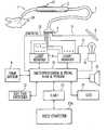
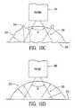
- FIGS. 10A , 10 B, 10 C and 10 Dillustrate and describe other fiber optic bundle configurations that may be used in accordance with yet other preferred embodiments of the present invention
- FIG. 11illustrates a linear optical sensor array that may be used in certain embodiments of the present invention
- FIG. 12illustrates a matrix optical sensor array that may be used in certain embodiments of the present invention
- FIGS. 13A and 13Billustrate certain optical properties of a filter array that may be used in certain embodiments of the present invention
- FIGS. 14A and 14Billustrate examples of received light intensities of receivers used in certain embodiments of the present invention
- FIG. 15is a flow chart illustrating audio tones that may be used in certain preferred embodiments of the present invention.
- FIG. 16is a flow chart illustrating a dental prosthesis manufacturing method in accordance with a preferred embodiment of the present invention.
- FIGS. 17A and 17Billustrate a positioning implement used in certain embodiments of the present invention
- FIG. 18is a flow chart illustrating a patient database method in accordance with certain embodiments of the present invention.
- FIG. 19illustrates an integrated unit in accordance with the present invention that includes a measuring device and other implements.
- objectfor example. It should be understood that an exemplary use of the present invention is in the field of dentistry, and thus the object typically should be understood to include teeth, dentures, dental-type cements or the like, although for discussion purposes in certain instances reference is only made to the “object.”
- FIG. 1an exemplary preferred embodiment of a color measuring system and method in accordance with the present invention will be described.
- Probe tip 1encloses a plurality of fiber optics, each of which may constitute one or more fiber optic fibers.
- the fiber optics contained within probe tip 1includes a single light source fiber optic and three light receiver fiber optics. The use of such fiber optics to measure the color of an object will be described later herein.
- Probe tip 1is attached to probe body 2 , on which is fixed switch 17 .
- Switch 17communicates with microprocessor 10 through wire 18 and provides, for example, a mechanism by which an operator may activate the device in order to make a color measurement.
- Fiber optics within probe tip 1terminate at the forward end thereof (i.e., the end away from probe body 2 ). The forward end of probe tip 1 is directed towards the surface of the object to be measured as described more fully below.
- the fiber optics within probe tip 1optically extend through probe body 2 and through fiber optic cable 3 to light sensors 8 , which are coupled to microprocessor 10 .
- microprocessor 10includes conventional associated components, such as memory (programmable memory, such as PROM, EPROM or EEPROM; working memory such as DRAMs or SRAMs; and/or other types of memory such as non-volatile memory, such as FLASH), peripheral circuits, clocks and power supplies, although for clarity such components are not explicitly shown.
- memoryprogrammable memory, such as PROM, EPROM or EEPROM
- working memorysuch as DRAMs or SRAMs
- non-volatile memorysuch as FLASH
- peripheral circuitssuch as non-volatile memory, such as FLASH
- Other types of computing devicesare used in other embodiments of the present invention.
- each of the three receiver fiber optics used in this embodimentis spliced into at least five smaller fiber optics ((generally denoted as fibers 7 ), which in this embodiment are fibers of equal diameter, but which in other embodiments may be of unequal diameter (such as a larger or smaller “height/angle” or perimeter fiber, as more fully described herein).
- fibers 7are fibers of equal diameter, but which in other embodiments may be of unequal diameter (such as a larger or smaller “height/angle” or perimeter fiber, as more fully described herein).
- One of the fibers of each group of five fiberspasses to light sensors 8 through a neutral density filter (as more fully described with reference to FIG.
- splicing connector 4is not used, and fiber bundles of, for example, five or more fibers each extend from light sensors 8 to the forward end of probe tip 1 .
- unused fibers or other materialsmay be included as part of a bundle of fibers for purposes of, for example, easing the manufacturing process for the fiber bundle.
- a plurality of light receiver fiber optics(such as fibers 7 ) are presented to light sensors 8 , with the light from the light receiver fiber optics representing light reflected from object 20 . While the various embodiments describe herein present tradeoffs and benefits that may not have been apparent prior to the present invention (and thus may be independently novel), what is important for the present discussion is that light from fiber optics at the forward end of probe tip 1 is presented to color sensors 8 for color measurement and angle/height determination, etc.
- Light source 11 in the preferred embodimentis a halogen light source (of, for example, 5-100 watts, with the particular wattage chosen for the particular application), which may be under the control of microprocessor 10 .
- the light from light source 11reflects from cold mirror 6 and into source fiber optic 5 .
- Source fiber optic 5passes through to the forward end of probe tip 1 and provides the light stimulus used for purposes of making the measurements described herein.
- Cold mirror 6reflects visible light and passes infra-red light, and is used to reduce the amount of infra-red light produced by light source 11 before the light is introduced into source fiber optic 5 .
- Fiber 15receives light directly from light source 11 and passes through to light sensors 8 (which may be through a neutral density filter).
- Microprocessor 10monitors the light output of light source 11 through fiber 15 , and thus may monitor and, if necessary compensate for, drift of the output of light source 11 .
- microprocessor 10also may sound an alarm (such as through speaker 16 ) or otherwise provide some indication if abnormal or other undesired performance of light source 11 is detected.
- microprocessor 10processes the data from light sensors 8 to produce a measurement of color and/or other characteristics.
- Microprocessor 10also is coupled to key pad switches 12 , which serve as an input device. Through key pad switches 12 , the operator may input control information or commands, or information relating to the object being measured or the like.
- key pad switches 12or other suitable data input devices (such as push button, toggle, membrane or other switches or the like), serve as a mechanism to input desired information to microprocessor 10 .
- Microprocessor 10also communicates with UART 13 , which enables microprocessor 10 to be coupled to an external device such as computer 13 A.
- color data provided by microprocessor 10may be processed as desired for the particular application, such as for averaging, format conversion or for various display or print options, etc.
- UART 13is configured so as to provide what is known as a RS232 interface, such as is commonly found in personal computers.
- Microprocessor 10also communicates with LCD 14 for purposes of displaying status, control or other information as desired for the particular application. For example, color bars, charts or other graphic representations of the color or other collected data and/or the measured object or tooth may be displayed. In other embodiments, other display devices are used, such as CRTs, matrix-type LEDs, lights or other mechanisms for producing a visible indicia of system status or the like.
- LCD 14may provide an indication that the system is stable, ready and available for taking color measurements.
- Speaker 16serves to provide audio feedback to the operator, which may serve to guide the operator in the use of the device. Speaker 16 also may serve to provide status or other information altering the operator of the condition of the system, including an audio tone, beeps or other audible indication (i.e., voice) that the system is initialized and available for taking measurements. Speaker 16 also may present audio information indicative of the measured data, shade guide or reference values corresponding to the measured data, or an indication of the status of the color measurements.
- Microprocessor 10also receives an input from temperature sensor 9 .
- temperature sensor 9serves to provide temperature information to microprocessor 10 .
- color filterssuch as may be included in light sensors 8 , are sensitive to temperature, and operate reliably only over a certain temperature range.
- microprocessor 10may compensate for temperature variations of the color filters.
- the color filtersare characterized as to filtering characteristics as a function of temperature, either by data provided by the filter manufacturer, or through measurement as a function of temperature.
- Such filter temperature compensation datamay be stored in the form of a look-up table in memory, or may be stored as a set of polynomial coefficients from which the temperature characteristics of the filters may be computed by microprocessor 10 .
- microprocessor 10Under control of microprocessor 10 , which may be in response to operator activation (through, for example, key pad switches 12 or switch 17 ), light is directed from light source 11 , and reflected from cold mirror 6 through source fiber optic 5 (and through fiber optic cable 3 , probe body 2 and probe tip 1 ) and is directed onto object 20 . Light reflected from object passes through the receiver fiber optics in probe tip 1 to light sensors 8 (through probe body 2 , fiber optic cable 3 and fibers 7 ). Based on the information produced by light sensors 8 , microprocessor 10 produces a color measurement result or other information to the operator. Color measurement or other data produced by microprocessor 10 may be displayed on display 14 , passed through UART 13 to computer 13 A, or used to generate audio information that is presented to speaker 16 . Other operational aspects of the preferred embodiment illustrated in FIG. 1 will be explained hereinafter.
- a preferred embodiment of the fiber optic arrangement presented at the forward end of probe tip 1will now be described.
- a preferred embodiment of the present inventionutilizes a single central light source fiber optic, denoted as light source fiber optic S, and a plurality of perimeter light receiver fiber optics, denoted as light receivers R 1 , R 2 and R 3 .
- a preferred embodiment of the present inventionutilizes three perimeter fiber optics, although in other embodiments two, four or some other number of receiver fiber optics are utilized.
- the perimeter light receiver fiber opticsserve not only to provide reflected light for purposes of making the color measurement, but such perimeter fibers also serve to provide information regarding the angle and height of probe tip 1 with respect to the surface of the object that is being measured, and also may provide information regarding the surface characteristics of the object that is being measured.
- receiver fiber optics R 1 to R 3are positioned symmetrically around source fiber optic S, with a spacing of about 120 degrees from each other. It should be noted that spacing t is provided between receiver fiber optics R 1 to R 3 and source fiber optic S. While the precise angular placement of the receiver fiber optics around the perimeter of the fiber bundle in general is not critical, it has been determined that three receiver fiber optics positioned 120 degrees apart generally may give acceptable results. As discussed above, in certain embodiments light receiver fiber optics R 1 to R 3 each constitute a single fiber, which is divided at splicing connector 4 (refer again to FIG.
- light receiver fiber optics R 1 to R 3each constitute a bundle of fibers, numbering, for example, at least five fibers per bundle. It has been determined that, with available fibers of uniform size, a bundle of, for example, seven fibers may be readily produced (although as will be apparent to one of skill in the art, the precise number of fibers may be determined in view of the desired number of receiver fiber optics, manufacturing considerations, etc.).
- receiver fiber optics R 1 to R 3may serve to detect whether, for example, the angle of probe tip 1 with respect to the surface of the object being measured is at 90 degrees, or if the surface of the object being measured contains surface texture and/or spectral irregularities. In the case where probe tip 1 is perpendicular to the surface of the object being measured and the surface of the object being measured is a diffuse reflector, then the light intensity input into the perimeter fibers should be approximately equal.
- spacing tserves to adjust the optimal height at which color measurements should be made (as more fully described below), and also ensures that the light reflected into receiver fiber optics R 1 to R 3 is at an angle for diffuse reflection, which helps to reduce problems associated with measurements of “hot spots” on the surface of the object being measured.
- area between the fiber optics on probe tip 1may be wholly or partially filled with a non-reflective material and/or surface (which may be a black mat, contoured or other non-reflective surface). Having such exposed area of probe tip 1 non-reflective helps to reduce undesired reflections, thereby helping to increase the accuracy and reliability of the present invention.
- Fibers 7represent light receiving fiber optics, which transmit light reflected from the object being measured to light sensors 8 .
- sixteen sensors(two sets of eight) are utilized, although for ease of discussion only 8 are illustrated in FIG. 3 (in this preferred embodiment, the circuitry of FIG. 3 is duplicated, for example, in order to result in sixteen sensors). In other embodiments, other numbers of sensors are utilized in accordance with the present invention.
- sensing elements 24include light-to-frequency converters, manufactured by Texas Instruments and sold under the part number TSL230.
- Such convertersconstitute, in general, photo diode arrays that integrate the light received from fibers 7 and output an AC signal with a frequency proportional to the intensity (not frequency) of the incident light.
- the basic principle of such devicesis that, as the intensity increases, the integrator output voltage rises more quickly, and the shorter the integrator rise time, the greater the output frequency.
- the outputs of the TSL230 sensorsare TTL or CMOS compatible digital signals, which may be coupled to various digital logic devices.
- sensing elements 24are, in this embodiment, asynchronous signals of frequencies depending upon the light intensity presented to the particular sensing elements, which are presented to processor 26 .
- processor 26is a Microchip PIC16C55 microprocessor, which as described more fully herein implements an algorithm to measure the frequencies of the signals output by sensing elements 24 .
- processor 26measures the frequencies of the signals output from sensing elements 24 .
- processor 26implements a software timing loop, and at periodic intervals processor 26 reads the states of the outputs of sensing elements 24 .
- An internal counteris incremented each pass through the software timing loop.
- the accuracy of the timing loopgenerally is determined by the crystal oscillator time base (not shown in FIG. 3 ) coupled to processor 26 (such oscillators typically are quite stable).
- processor 26After reading the outputs of sensing elements 24 , processor 26 performs an exclusive OR (“XOR”) operation with the last data read (in a preferred embodiment such data is read in byte length). If any bit has changed, the XOR operation will produce a 1, and, if no bits have changed, the XOR operation will produce a 0.
- XORexclusive OR
- processor 26analyzes the stored input bytes and internal counter states. There should be 2 to 16 saved inputs (for the 8 total sensors of FIG. 3 ) and counter states (if two or more inputs change at the same time, they are saved simultaneously).
- the stored values of the internal countercontains information determinative of the period of the signals received from sensing elements 24 .
- the periodmay be calculated.
- Such periods calculated for each of the outputs of sensing elementsis provided by processor 26 to microprocessor 10 (see, e.g., FIG. 1 ). From such calculated periods, a measure of the received light intensities may be calculated.
- sensing circuitry and methodology illustrated in FIG. 3have been determined to provide a practical and expedient manner in which to measure the light intensities received by sensing elements 24 .
- other circuits and methodologiesare employed (other exemplary sensing schemes are described elsewhere herein).
- one of fibers 7measures light source 11 , which may be through a neutral density filter, which serves to reduce the intensity of the received light in order maintain the intensity roughly in the range of the other received light intensities.
- Three of fibers 7also are from perimeter receiver fiber optics R 1 to R 3 (see, e.g., FIG. 2 ) and also may pass through neutral density filters. Such receiving fibers 7 serve to provide data from which angle/height information and/or surface characteristics may be determined.
- the remaining twelve fibers (of the preferred embodiment's total of 16 fibers) of fibers 7pass through color filters and are used to produce the color measurement.
- the color filtersare Kodak Sharp Cutting Wratten Gelatin Filters, which pass light with wavelengths greater than the cut-off value of the filter (i.e., redish values), and absorb light with wavelengths less than the cut-off value of the filter (i.e., bluish values).
- “Sharp Cutting” filtersare available in a wide variety of cut-off frequencies/wavelengths, and the cut-off values generally may be selected by proper selection of the desired cut-off filter.
- the filter cut-off valuesare chosen to cover the entire visible spectrum and, in general, to have band spacings of approximately the visible band range (or other desired range) divided by the number of receivers/filters. As an example, 700 nanometers minus 400 nanometers, divided by 11 bands (produced by twelve color receivers/sensors), is roughly 30 nanometer band spacing.
- band 1400 nm to 430 nm
- intensity values that may result from filtering with such an arrayare more fully described in connection with FIGS. 13A to 14 B.
- the specific characteristics of the light source, filters, sensors and fiber optics, etc.are normalized/calibrated by directing the probe towards, and measuring, a known color standard.
- Such normalization/calibrationmay be performed by placing the probe in a suitable fixture, with the probe directed from a predetermined position (i.e., height and angle) from the known color standard.
- Such measured normalization/calibration datamay be stored, for example, in a look-up table, and used by microprocessor 10 to normalize or correct measured color or other data. Such procedures may be conducted at start-up, at regular periodic intervals, or by operator command, etc.
- FIG. 3provides a practical and expedient way to determine the intensity by color of the light reflected from the surface of the object being measured.
- spectral datamay be utilized in a variety of ways.
- spectral datamay be displayed directly as intensity-wavelength band values.
- tristimulus type valuesmay be readily computed (through, for example, conventional matrix math), or any other desired color values.
- the color datais output in the form of a closest match or matches of dental shade guide value(s).
- various existing shade guidessuch as the shade guides produced by Vita Zahnfabrik
- the color measurement dataare used to select the closest shade guide value.
- the color measurement dataare used (such as with look-up tables) to select materials for the composition of paint or ceramics such as for prosthetic teeth.
- a light source with an ultraviolet componentmay be used to produce more accurate color data of such objects.
- a tungsten/halogen sourcesuch as used in a preferred embodiment
- a UV light sourcesuch as a mercury vapor, xenon or other fluorescent light source, etc.
- a separate UV light sourcecombined with a visible-light-blocking filter, may be used to illuminate the object.
- Such a UV light sourcemay be combined with light from a red LED (for example) in order to provide a visual indication of when the UV light is on and also to serve as an aid for the directional positioning of the probe operating with such a light source.
- a second measurementmay be taken using the UV light source in a manner analogous to that described earlier, with the band of the red LED or other supplemental light source being ignored. The second measurement may thus be used to produce an indication of the fluorescence of the tooth or other object being measured.
- a silica fiber optictypically would be required to transmit the light to the object (standard fiber optic materials such as glass and plastic do not propagate UV light in a desired manner, etc.).
- the present inventionutilizes a plurality of perimeter receiver fiber optics spaced apart from and around a central source fiber optic to measure color and determine information regarding the height and angle of the probe with respect to the surface of the object being measured, which may include surface characteristic information, etc.
- a principle underlying this aspect of the present inventionwill now be described with reference to FIGS. 4A to 4 C.
- FIG. 4Aillustrates a typical step index fiber optic consisting of a core and a cladding.
- the corehas an index of refraction of n 0
- the claddinghas an index of refraction of n 1 .
- Typical fiber opticshave an aperture of 0.5, and thus an acceptance/critical angle of 60°.
- a fiber opticas a light source.
- One endis illuminated by a light source (such as light source 11 of FIG. 1 ), and the other is held near a surface.
- the fiber opticwill emit a cone of light as illustrated in FIG. 4 A. If the fiber optic is held perpendicular to a surface it will create a circular light pattern on the surface. As the fiber optic is raised, the radius r of the circle will increase. As the fiber optic is lowered, the radius of the light pattern will decrease. Thus, the intensity of the light (light energy per unit area) in the illuminated circular area will increase as the fiber optic is lowered and will decrease as the fiber optic is raised.
- a fiber optic utilized as a light receiver near a surfacewill only accept and propagate light from the circular area of radius r on the surface. As the fiber optic is raised from the surface, the area increases. As the fiber optic is lowered to the surface, the area decreases.
- One fiber opticis a source fiber optic
- the other fiber opticis a receiver fiber optic.
- the source fiber opticemits a cone of light that illuminates a circular area of radius r.
- the receiver fiber opticcan only accept light that is within its acceptance angle phi, or only light that is received within a cone of angle phi.
- the only light availableis that emitted by the source fiber optic
- the only light that can be accepted by the receiver fiber opticis the light that strikes the surface at the intersection of the two circles as illustrated in FIG. 4 C.
- the proportion of the intersection of the two circular areas relative to the circular area of the source fiber opticincreases.
- the proportion of the intersection of the two circular areas to the circular area of the source fiber opticdecreases. If the fiber optics are held too close to the surface, the circular areas will no longer intersect and no light emitted from the source fiber optic will be received by the receiver fiber optic.
- the intensity of the light in the circular area illuminated by the source fiberincreases as the fiber is lowered to the surface.
- the intersection of the two conesdecreases as the fiber optic pair is lowered.
- the intensity of light received by the receiver fiber opticincreases to a maximal value, and then decreases sharply is the fiber optic pair is lowered still further to the surface.
- the intensitywill decrease essentially to zero (assuming the object being measured is not translucent, as described more fully herein), and will remain essentially zero until the fiber optic pair is in contact with the surface.
- a source-receiver pair of fiber optics as described aboveare positioned near a surface and as their height is varied, the intensity of light received by the receiver fiber optic reaches a maximal value at a critical height h c .
- the critical height h cis a function primarily of the geometry of fixed parameters, such as fiber apertures, fiber diameters and fiber spacing. Since the receiver fiber optic in the illustrated arrangement is only detecting a maximum value and not attempting to quantify the value, its maximum is independent of the surface characteristics. It is only necessary that the surface reflect sufficient light from the intersecting area of the source and receiver fiber optics to be within the detection range of the receiver fiber optic light sensor. Thus, red or green or blue or any color surface will all exhibit a maximum at the same critical height h c .
- smooth reflecting surfaces and rough surfacesalso will have varying intensity values at the maximal value, but generally speaking all such surfaces will exhibit a maximum at the same critical height h c .
- the actual value of the light intensitywill be a function of the color of the surface and of the surface characteristics, but the height where the maximum intensity value occurs in general will not.
- FIGS. 5A and 5Bthe intensity of light received as a fiber optic source-receiver pair is moved to and from a surface will now be described.
- FIG. 5Aillustrates the intensity of the received light as a function of time.
- FIG. 5Billustrates the height of the fiber optic pair from the surface of the object being measured.
- FIGS. 5A and 5Billustrate (for ease of discussion) a relatively uniform rate of motion of the fiber optic pair to and from the surface of the object being measured (although similar illustrations/analysis would be applicable for non-uniform rates as well).
- FIG. 5Aillustrates the intensity of received light as the fiber optic pair is moved to and then from a surface. While FIG. 5A illustrates the intensity relationship for a single receiver fiber optic, similar intensity relationships would be expected to be observed for other receiver fiber optics, such as, for example, the multiple receiver fiber optics of FIGS. 1 and 2 . In general with the preferred embodiment described above, all fifteen fiber optic receivers (of fibers 7 ) will exhibit curves similar to that illustrated in FIG. 5 A.
- FIG. 5Aillustrates five regions.
- region 1the probe is moved towards the surface of the object being measured, which causes the received light intensity to increase.
- region 2the probe is moved past the critical height, and the received light intensity peaks and then falls off sharply.
- region 3the probe essentially is in contact with the surface of the object being measured. As illustrated, the received intensity in region 3 will vary depending upon the translucence of the object being measured. If the object is opaque, the received light intensity will be very low, or almost zero (perhaps out of range of the sensing circuitry). If the object is translucent, however, the light intensity will be quite high, but in general should be less than the peak value.
- region 4the probe is lifted and the light intensity rises sharply to a maximum value.
- region 5the probe is lifted further away from the object, and the light intensity decreases again.
- peaks P 1 and P 2 produced by a receive fiber opticare the same value, this generally is an indication that the probe has been moved to and from the surface of the object to be measured in a consistent manner. If peaks P 1 and P 2 ire of different values, then these may be an indication that the probe was not moved to and from the surface of the object in a desired manner, or that the surface is curved or textured, as described more fully herein. In such a case, the data may be considered suspect and rejected.
- peaks P 1 and P 2 for each of the perimeter fiber opticsshould occur at the same critical height (assuming the geometric attributes of the perimeter fiber optics, such as aperture, diameter and spacing from the source fiber optic, etc.).
- the perimeter fiber optics of a probe moved in a consistent, perpendicular manner to and from the surface of the object being measuredshould have peaks P 1 and P 2 that occur at the same critical height.
- Monitoring receiver fibers from the perimeter receiver fiber optics and looking for simultaneous (or near simultaneous, e.g., within a predetermined range) peaks P 1 and P 2provides a mechanism for determining if the probe is held at a desired perpendicular angle with respect to the object being measured.
- the relative intensity level in region 3serves as an indication of the level of translucency of the object being measured.
- such principlesgenerally are applicable to the totality of receiver fiber optics in the probe (see, e.g., fibers 7 of FIGS. 1 and 3 ). Based on such principles, measurement techniques in accordance with the present invention will now be described.
- FIG. 6is a flow chart illustrating a measuring technique in accordance with the present invention.
- Step 49indicates the start or beginning of a color measurement.
- any equipment initialization, diagnostic or setup proceduresmay be performed. Audio or visual information or other indicia may be given to the operator to inform the operator that the system is available and ready to take a measurement. Initiation of the color measurement commences by the operator moving the probe towards the object to be measured, and may be accompanied by, for example, activation of switch 17 (see FIG. 1 ).
- step 50the system on a continuing basis monitors the intensity levels for the receiver fiber optics (see, e.g., fibers 7 of FIG. 1 ). If the intensity is rising, step 50 is repeated until a peak is detected. If a peak is detected, the process proceeds to step 52 . In step 52 , measured peak intensity P 1 , and the time at which such peak occurred, are stored in memory (such as in memory included as a part of microprocessor 10 ), and the process proceeds to step 54 . In step 54 , the system continues to monitor the intensity levels of the receiver fiber optics. If the intensity is falling, step 54 is repeated.
- step 56the measured surface intensity (IS) is stored in memory, and the process proceeds to step 58 .
- step 58the system continues to monitor the intensity levels of the receiver fibers. If the intensity is rising, step 58 is repeated until a peak is detected. If a peak is detected, the process proceeds to step 60 .
- step 60measured peak intensity P 2 , and the time at which such peak occurred, are stored in memory, and the process proceeds to step 62 .
- step 62the system continues to monitor the intensity levels of the receiver fiber optics. Once the received intensity levels begin to fall from peak P 2 , the system perceives that region 5 has been entered (see, e.g., FIG. 5 A), and the process proceeds to step 64 .
- step 64the system, under control of microprocessor 10 , may analyze the collected data taken by the sensing circuitry for the various receiver fiber optics.
- step 64peaks P 1 and P 2 of one or more of the various fiber optics may be compared. If any of peaks P 1 and P 2 for any of the various receiver fiber optics have unequal peak values, then the color data may be rejected, and the entire color measuring process repeated.
- peaks P 1 and P 2may be indicative, for example, that the probe was moved in a non-perpendicular or otherwise unstable manner (i.e., angular or lateral movement), and, for example, peak P 1 may be representative of a first point on the object, while peak P 2 may be representative of a second point on the object.
- peak P 1may be representative of a first point on the object
- peak P 2may be representative of a second point on the object.
- step 66the system analyzes the data taken from the neutral-density-filtered receivers from each of the perimeter fiber optics (e.g., R 1 to R 3 of FIG. 2 ). If the peaks of the perimeter fiber optics did not occur at or about the same point in time, this may be indicative, for example, that the probe was not held perpendicular to the surface of the object being measured. As non-perpendicular alignment of the probe with the surface of the object being measured may cause suspect results, in a preferred embodiment of the present invention, color data taken in such circumstances are rejected in step 66 .
- step 66includes an analysis of peak values P 1 and P 2 of the perimeter fiber optics.
- the systemseeks to determine if the peak values of the perimeter fiber optics (perhaps normalized with any initial calibration data) are equal within a defined range. If the peak values of the perimeter fiber optics are within the defined range, the data may be accepted, and if not, the data may be rejected.
- a combination of simultaneous peaking and equal value detectionare used as acceptance/rejection criteria for the color data, and/or the operator may have the ability (such as through key pad switches 12 ) to control one or more of the acceptance criteria ranges.
- the sensitivity of the systemmay be controllably altered by the operator depending upon the particular application and operative environment, etc.
- step 68the color data may be processed in a desired manner to produce output color measurement data.
- datamay be normalized in some manner, or adjusted based on temperature compensation or other data detected by the system.
- the dataalso may be converted to different display or other formats, depending on the intended use of the color data.
- the data indicative of the translucence of the objectalso may be quantified and/or displayed in step 68 .
- the processmay proceed to starting step 49 , or the process may be terminated, etc.
- three light intensity valuesare stored per receiver fiber optic to make color and translucency measurements. If stored peak values P 1 and P 2 are not equal (for some or all of the receivers), this is an indication that the probe was not held steady over one area, and the data may be rejected (in other embodiments, the data may not be rejected, although the resulting data may be used to produce an average of the measured color data).
- peak values P 1 and P 2 for the three neutral density perimeter fiber opticsshould be equal or approximately equal; if this is not the case, then this is an indication that the probe was not held perpendicular or a curved surface is being measured.
- the systemattempts to compensate for curved surfaces and/or non-perpendicular angles. In any event, if the system cannot make a color measurement, or if the data is rejected because peak values P 1 and P 2 are unequal to an unacceptable degree, then the operator is notified so that another measurement or other action may be taken (such as adjust the sensitivity).
- color measurementsmay be taken of an object, with accepted color data having height and angular dependencies removed. Data not taken at the critical height, or data not taken with the probe perpendicular to the surface of the object being measured, etc., are rejected in a preferred embodiment of the present invention.
- data received from the perimeter fiber opticsmay be used to calculate the angle of the probe with respect to the surface of the object being measured, and in such embodiments non-perpendicular or curved surface color data may be compensated instead of rejected.
- peak values P 1 and P 2 for the neutral density perimeter fiber opticsprovide a measure of the luminance (gray value) of the surface of the object being measured, and also may serve to quantify the color value.
- the translucency of the object being measuredmay be quantified as a ratio or percentage, such as, for example, (IS/P 1 ) ⁇ 100%. In other embodiments, other methods of quantifying translucency data provided in accordance with the present invention are utilized.
- data generated in accordance with the present inventionmay be used to implement an automated material mixing/generation machine.
- Certain objects/materialssuch as dental prostheses, are made from porcelain or other powders/materials that may be combined in the correct ratios to form the desired color of the object/prosthesis.
- Certain powdersoften contain pigments that generally obey Beer's law and/or act in accordance with Kubelka-Munk equations when mixed in a recipe.
- Color and other data taken from a measurement in accordance with the present inventionmay be used to determine or predict desired quantities of pigment or other materials for the recipe. Porcelain powders and other materials are available in different colors, opacities, etc.
- Certain objectsmay be layered to simulate the degree of translucency of the desired object (such as to simulate a human tooth).
- Data generated in accordance with the present inventionalso may be used to determine the thickness and position of the porcelain or other material layers to more closely produce the desired color, translucency, surface characteristics, etc.
- the material recipemay be adjusted to include a desired quantity of fluorescing-type material.
- surface characteristics (such as texture) informationmay be used to add a texturing material to the recipe, all of which may be carried out in accordance with the present invention.
- FIGS. 7A and 7Billustrate a protective cap that may be used to fit over the end of probe tip 1 .
- a protective capconsists of body 80 , the end of which is covered by optical window 82 , which in a preferred embodiment consists of a structure having a thin sapphire window.
- body 80consists of stainless steel.
- Body 80fits over the end of probe tip 1 and may be held into place by, for example, indentations formed in body 80 , which fit with ribs 84 (which may be a spring clip or other retainer) formed on probe tip 1 .
- ribs 84which may be a spring clip or other retainer
- the protective capmay be removed from probe tip 1 and sterilized in a typical autoclave, hot steam or other sterilizing system.
- the thickness of the sapphire windowshould be less than the critical height of the probe in order to preserve the ability to detect peaking in accordance with the present invention. It also is believed that sapphire windows may be manufactured in a reproducible manner, and thus any light attenuation from one cap to another may be reproducible. In addition, any distortion of the color measurements produced by the sapphire window may be calibrated out by microprocessor 10 .
- body 80has a cap with a hole in the center (as opposed to a sapphire window), with the hole positioned over the fiber optic source/receivers.
- the cap with the holeserves to prevent the probe from coming into contact with the surface, thereby reducing the risk of contamination.
- FIGS. 8A and 8Billustrate another embodiment of a removable probe tip that may be used to reduce contamination in accordance with the present invention.
- probe tip 88is removable, and includes four (or a different number, depending upon the application) fiber optic connectors 90 , which are positioned within optical guard 92 .
- Optical guard 92serves to prevent “cross talk” between adjacent fiber optics.
- removable tip 88is secured in probe tip housing 92 by way of spring clip 96 (other removable retaining implements are utilized in other embodiments).
- Probe tip housing 92may be secured to base connector 94 by a screw or other conventional fitting.
- Removable tip 88also may be sterilized in a typical autoclave, hot steam or other sterilizing system.
- the entire probe tip assemblyis constructed so that it may be readily disassembled for cleaning or repair.
- FIG. 9illustrates a cross section of the probe tip fiber optics used in this embodiment.
- Probe tip 100includes central source fiber optic 106 , surrounded by (and spaced apart from) three perimeter receiver fiber optics 104 and three color receiver fiber optics 102 .
- Three perimeter receiver fiber optics 104are optically coupled to neutral density filters and serve as height/angle sensors in a manner analogous to the embodiment describe above.
- Three color receiver fiber opticsare optically coupled to suitable tristimulus filters, such as red, green and blue filters.
- tristimulus filterssuch as red, green and blue filters.
- perimeter fiber optics 104may be used to detect simultaneous peaking or otherwise whether the probe is perpendicular to the object being measured.
- taking color measurement data at the critical heightalso may be used with this embodiment.
- FIG. 10Aillustrates an embodiment of the present invention, similar to the embodiment discussed with reference to FIG. 9 .
- Probe tip 100includes central source fiber optic 106 , surrounded by (and spaced apart from) three perimeter receiver fiber optics 104 and a plurality of color receiver fiber optics 102 .
- the number of color receiver fiber optics 102 , and the filters associated with such receiver fiber optics 102may be chosen based upon the particular application. As with the embodiment of FIG. 9 , the process described with reference to FIG. 6 generally is applicable to this embodiment.
- FIG. 10Billustrates an embodiment of the present invention in which there are a plurality of receiver fiber optics that surround central source fiber optic 240 .
- the receiver fiber opticsare arranged in rings surrounding the central source fiber optic.
- FIG. 10Billustrates three rings of receiver fiber optics (consisting of fiber optics 242 , 244 and 246 , respectively), in which there are six receiver fiber optics per ring.
- the ringsmay be arranged in successive larger circles as illustrated to cover the entire area of the end of the probe, with the distance from each receiver fiber optic within a given ring to the central fiber optic being equal (or approximately so).
- Central fiber optic 240is utilized as the light source fiber optic and is connected to the light source in a manner similar to light source fiber optic 5 illustrated in FIG. 1 .
- the plurality of receiver fiber opticsare each coupled to two or more fiber optics in a manner similar to the arrangement illustrated in FIG. 1 for splicing connector 4 .
- One fiber optic from such a splicing connector for each receiver fiber opticpasses through a neutral density filter and then to light sensor circuitry similar to the light sensor circuitry illustrated in FIG. 3.
- a second fiber optic from the splicing connector per receiver fiber opticpasses through a Sharp Cutting Wrattan Gelatin Filter and then to light sensor circuitry as discussed elsewhere herein.
- each of the receiver fiber optics in the probe tipincludes both color measuring elements and neutral light measuring or “perimeter” elements.
- FIG. 10Dillustrates the geometry of probe 260 (such as described above) illuminating an area on flat diffuse surface 272 .
- Probe 260creates light pattern 262 that is reflected diffusely from surface 272 in uniform hemispherical pattern 270 . With such a reflection pattern, the reflected light that is incident upon the receiving elements in the probe will be equal (or nearly equal) for all elements if the probe is perpendicular to the surface as described above herein.
- FIG. 10Cillustrates a probe illuminating rough surface 268 or a surface that reflects light spectrally. Spectral reflected light will exhibit hot spots or regions where the reflected light intensity is considerably greater than it is on other areas. The reflected light pattern will be uneven when compared to a smooth surface as illustrate in FIG. 10 D.
- the probemay be utilized to determine the surface texture of the surface as well as being able to measure the color and translucency of the surface as described earlier herein. If the light intensity received by the receiver fiber optics is equal for all fiber optics within a given ring of receiver fiber optics, then generally the surface is diffuse and smooth. If, however, the light intensity of receiver fibers in a ring varies with respect to each other, then generally the surface is rough or spectral. By comparing the light intensities measured within receiver fiber optics in a given ring and from ring to ring, the texture and other characteristics of the surface may be quantified.
- FIG. 11illustrates an embodiment of the present invention in which linear optical sensors and a color gradient filter are utilized instead of light sensors 8 (and filters 22 , etc.).
- Receiver fiber optics 7which may be optically coupled to probe tip 1 as with the embodiment of FIG. 1 , are optically coupled to linear optical sensor 112 through color gradient filter 110 .
- color gradient filter 110may consist of series of narrow strips of cut-off type filters on a transparent or open substrate, which are constructed so as to positionally correspond to the sensor areas of linear optical sensor 112 .
- An example of a commercially available linear optical sensor 112is Texas Instruments part number TSL213, which has 61 photo diodes in a linear array.
- Light receiver fiber optics 7are arranged correspondingly in a line over linear optical sensor 112 .
- the number of receiver fiber opticsmay be chosen for the particular application, so long as enough are included to more or less evenly cover the full length of color gradient filter 110 .
- the lightis received and output from receiver fiber optics 7 , and the light received by linear optical sensor 112 is integrated for a short period of time (determined by the light intensity, filter characteristics and desired accuracy).
- the output of linear array sensor 112is digitized by ADC 114 and output to microprocessor 116 (which may the same processor as microprocessor 10 or another processor).
- perimeter receiver fiber opticsmay be used as with the embodiment of FIG. 1 , and in general the process described with reference to FIG. 6 is applicable to this embodiment.
- FIG. 12illustrates an embodiment of the present invention in which a matrix optical sensor and a color filter grid are utilized instead of light sensors 8 (and filters 22 , etc.).
- Receiver fiber optics 7which may be optically coupled to probe tip 1 as with the embodiment of FIG. 1 , are optically coupled to matrix optical sensor 122 through filter grid 120 .
- Filter grid 120is a filter array consisting of a number of small colored spot filters that pass narrow bands of visible light. Light from receiver fiber optics 7 pass through corresponding filter spots to corresponding points on matrix optical sensor 122 .
- matrix optical sensor 122may be a monochrome optical sensor array, such as CCD-type or other type of light sensor element such as may be used in a video camera.
- matrix optical sensor 122The output of matrix optical sensor 122 is digitized by ADC 124 and output to microprocessor 126 (which may the same processor as microprocessor 10 or another processor). Under control of microprocessor 126 , matrix optical sensor 126 collects color data from receiver fiber optics 7 through color filter grid 120 .
- perimeter receiver fiber opticsmay be used as with the embodiment of FIG. 1 , and in general the process described with reference to FIG. 6 also is applicable to this embodiment.
- spectral color photometersor tristimulus-type colorimeters
- perimeter receiver fiber opticsused to collect color data essentially free from height and angular deviations.
- the present inventionenables color measurements to be taken at a critical height from the surface of the object being measured, and thus color data may be taken without physical contact with the object being measured (in such embodiments, the color data is taken only by passing the probe through region 1 and into region 2 , but without necessarily going into region 3 of FIGS. 5 A and 5 B). Such embodiments may be utilized if contact with the surface is undesirable in a particular application.
- FIG. 13Aillustrates the properties of a single Kodak Sharp Cutting Wratten Gelatin Filter discussed in connection with FIG. 3 .
- Such a cut-off filterpasses light below a cut-off frequency (i.e., above a cut-off wavelength).
- Such filtersmay be manufactured to have a wide range of cut-off frequencies/wavelengths.
- FIG. 13Billustrates a number of such filters, twelve in a preferred embodiment, with cut-off frequencies/wavelengths chosen so that essentially the entire visible band is covered by the collection of cut-off filters.
- FIGS. 14A and 14Billustrate exemplary intensity measurements using a cut-off filter arrangement such as illustrated in FIG. 13B , first in the case of a white surface being measured (FIG. 14 A), and also in the case of a blue surface being measured (FIG. 14 B).
- the neutrally filtered perimeter fiber opticswhich are used to detect height and angle, etc., generally will produce the highest intensity (although this depends at least in part upon the characteristics of the neutral density filters).
- the remaining intensitieswill gradually decrease in value as illustrated in FIG. 14 A.
- any color data detected that does not fit the decreasing intensity profiles of FIGS. 14A and 14Bmay be detected as an abnormality, and in certain embodiments detection of such a condition results in data rejection, generation of an error message or initiation of a diagnostic routine, etc.
- FIGS. 1 and 3Reference should be made to the FIGS. 1 and 3 and the related description for a detailed discussion of how such a cut-off filter arrangement may be utilized in accordance with the present invention.
- FIG. 15is a flow chart illustrating audio tones that may be used in certain preferred embodiments of the present invention. It has been discovered that audio tones (such as tones, beeps, voice or the like such as will be described) present a particularly useful and instructive means to guide an operator in the proper use of a color measuring system of the type described herein.
- audio tonessuch as tones, beeps, voice or the like such as will be described
- the operatormay initiate a color measurement by activation of a switch (such as switch 17 of FIG. 1 ) at step 150 . Thereafter, if the system is ready (set-up, initialized, calibrated, etc.), a lower-the-probe tone is emitted (such as through speaker 16 of FIG. 1 ) at step 152 .
- the systemattempts to detect peak intensity P 1 at step 154 . If a peak is detected, at step 156 a determination is made whether the measured peak P 1 meets the applicable criteria (such as discussed above in connection with FIGS. 5A , 5 B and 6 ). If the measured peak P 1 is accepted, a first peak acceptance tone is generated at step 160 .
- an unsuccessful toneis generated at step 158 , and the system may await the operator to initiate a further color measurement. Assuming that the first peak was accepted, the system attempts to detect peak intensity P 2 at step 162 . If a second peak is detected, at step 164 a determination is made whether the measured peak P 2 meets the applicable criteria. If the measured peak P 2 is accepted the process proceeds to color calculation step 166 (in other embodiments, a second peak acceptance tone also is generated at step 166 ). If the measured peak P 2 is not accepted, an unsuccessful tone is generated at step 158 , and the system may await the operator to initiate a further color measurement.
- a color calculationis made at step 166 (such as, for example, microprocessor 10 of FIG. 1 processing the data output from light sensors 8 , etc.).
- step 168a determination is made whether the color calculation meets the applicable criteria. If the color calculation is accepted, a successful tone is generated at step 170 . If the color calculation is not accepted, an unsuccessful tone is generated at step 158 , and the system may await the operator to initiate a further color measurement.
- audio tones presented to an operator in accordance with the particular operating state of the systemmay be greatly facilitated.
- Such audio informationalso tends to increase operator satisfaction and skill level, as, for example, acceptance tones provide positive and encouraging feedback when the system is operated in a desired manner.
- the color measuring systems and methods in accordance with the present inventionmay be applied to particular advantage in the field of dentistry, as will be more fully explained hereinafter.
- the present inventionincludes the use of such systems and methods to measure the color and other attributes of a tooth in order to prepare a dental prosthesis or intraoral tooth-colored fillings, or to select denture teeth or to determine a suitable cement color for porcelain/resin prostheses.
- the present inventionalso provides methods for storing and organizing measured data such as in the form of a patient database.
- FIG. 16is a flow chart illustrating a general dental application process flow for use of the color measuring systems and methods in accordance with the present invention.
- the color measuring systemmay be powered-up and stabilized, with any required initialization or other setup routines performed.
- an indication of the system statusmay be provided to the operator, such as through LCD 14 or speaker 16 of FIG. 1 .
- the probe tipmay be shielded or a clean probe tip may be inserted in order to reduce the likelihood of contamination (see, e.g., FIGS. 7A to 8 B and related description).
- a plastic or other shieldmay also be used, so long as it is constructed and/or positioned so as to not adversely affect the measurement process.
- the patient and the tooth to be measuredare prepared. Any required cleaning or other tooth preparation would be performed at step 202 . Any required patient consultation about the type of prosthesis or area of a tooth to be matched would be performed at (or before) step 202 .
- a positioning deviceis prepared at step 202 , such as is illustrated in FIGS. 17A and 17B .
- a black or other suitably-colored material 282which may adhere to tooth 280 (such as with a suitable adhesive), is formed to have opening 281 larger than the diameter of the measuring probe, with opening 281 centered on the area of tooth 280 to be measured.
- positioning device 282is formed in a manner to fit on/over tooth 280 (such as over the incisal edge of tooth 280 and/or over one or more adjacent teeth) so that it may be placed on/over tooth 280 in a repeatable manner.
- a positioning devicemay serve to ensure that the desired area of tooth 280 is measured, and also allows for repeat measurements of the same area for purposes of confirmation or the like. Any other pre-measurement activities may be performed at (or before) step 202 .
- the operatortypically a dentist or other dental professional moves the probe towards the area of the tooth to be measured.
- This processpreferably is conducted in accordance with the methodology described with reference to FIGS. 5A , 5 B and 6 , and preferably is accompanied by audio tones such as described with reference to FIG. 15 .
- the operatormay obtain color and translucency data, for example, from a desired area of the tooth to be measured.
- an accepted color measurementis made, or some indication is given to the operator that the measurement step needs to be repeated or some other action taken.
- the dentistmay operate on the desired tooth or teeth or take other action. Before or after such action, additional measurements may be taken as needed (see, e.g., FIG. 18 and related description).
- any data conversion or processing of data collected at step 204may be performed.
- any data conversion or processing of data collected at step 204may be performed.
- detailed color spectrum and translucency informationis generated.
- a dental labfor example, requires that the color be presented in Munsell format (i.e., chroma, hue and value), RGB values, XYZ coordinates, CIELAB values, Hunter values, or some other color data format.
- datamay be converted to such formats through conventional matrix math, for example. Such math may be performed by microprocessor 10 or computer 13 A of FIG.
- step 206may be omitted.
- step 206consists of data formatting, such as preparing the data for reproduction in hard copy, pictorial or other form, or for transmission as facsimile or modem data.
- a translucency factoris computed in a format suitable for the particular application.
- a surface texture or detail factoris computed in a format suitable for the particular application.
- a matchingis optionally attempted between the data produced at steps 204 and 206 (if performed) and a desired color (in other embodiments, the process may proceed from 204 directly to 210 , or alternatively steps 206 and 208 may be combined).
- shade guidesare available in the market, some of which are known in the industry as Vita shade guides, Bioform shade guides or other color matching standards, guides or references or custom shade guides.
- a lookup tableis prepared and loaded into memory (such as memory associated with microprocessor 10 or computer 13 A of FIG. 1 ), and an attempt is made to the closest match or matches of the collected data with the known shade guides, custom shade guides or reference values.
- a translucency factor and/or a surface texture or detail factoralso is used in an effort to select the best possible match.
- a material correlation lookup tableis accessed. Based on the color and translucency data obtained at step 204 , a proposed recipe of materials, pigments or other instruction information is prepared for a prosthesis or filling, etc., of the desired color and translucency, etc. With the detailed color and other information made available in accordance with the present invention, a direct correlation with the relevant constituent materials may be made. In still other embodiments, such information is made available to an automated mixing or manufacturing machine for preparation of prosthesis or material of the desired color and translucency, as more fully described elsewhere herein.
- the prosthesis, denture, intraoral tooth-colored filling material or other itemsare prepared.
- This stepmay be performed at a dental lab, or, in certain embodiments, at or near the dental operatory.
- relevant data produced at steps 204 , 206 and/or 208may be sent to the remote lab or facility by hardcopy, facsimile or modem or other transmission.
- a prosthesismay be prepared of a desirable color at step 210 .
- the prosthesis or other material prepared at step 210may be measured for confirmation purposes, again preferably conducted in accordance with the methodology described with reference to FIGS. 5A , 5 B and 6 , and preferably accompanied by audio tones such as described with reference to FIG. 15.
- a re-measure of the tooth in the patient's mouth, etc.also may be made at this step for confirmation purposes. If the confirmation process gives satisfactory results, the prosthesis, denture, composite filling or other material may be preliminarily installed or applied in the patient at step 214 .
- a re-measure of the prosthesis, denture, composite filling or other materialsoptionally may be made. If the results of step 216 are acceptable, then the prosthesis may be more permanently installed or applied in the patient at step 218 . If the results of step 216 are not acceptable, the prosthesis may be modified and/or other of the steps repeated as necessary in the particular situation.
- client database softwareis run on a computing device, such as computer 13 A of FIG. 1 .
- Such softwaremay include data records for each patient, including fields storing the history of dental services performed on the patient, information regarding the status or condition of the patient's teeth, billing, address and other information.
- Such softwaremay enter a mode by which it is in condition to accept color or data take in accordance with the present invention.
- the dentist or other dental professionalmay select parameters for a particular tooth of the patient to be measured.
- the dentistmay sector the tooth into one or more regions, such as a grid.
- regionssuch as a grid.
- the toothmay be sectored into four regions.
- Such parameterswhich may include a pictorial representation on the computer of the tooth sectored into four regions (such as by grid lines), along with tooth identification and patient information may be entered into the computer at this time.
- one or more measurements of the toothmay be taken, such as with a system and method as described in connection with FIGS. 1 , 5 A, 5 B and/or 6 .
- the number of such measurementspreferably is associated with the parameters entered at step 288 .
- the data collected from the measurement(s)may be sent to the computer for subsequent processing.
- four color measurementsmay be taken (for the four regions of the tooth in the above example) and sent to the computer, with the data for the four color measurements (such as RGB or other values) associated with the four regions in accordance with the entered parameters.
- the displayed pictorial representation of the toothmay have overlaid thereof data indicative of the color measurement(s).
- the data collected during the processmay be associatively stored as a part of the patient's dental records in the data base.
- captured images of one or more of the patient's teethalso may be associatively stored as part of the patient's dental records.
- a picture captured by the intraoral camerais overlaid with grid or sector lines (such as may be defined in step 288 ), with color or other data measured as described herein also overlaid over the captured image.
- the color or other datamay be electronically and visually associated with a picture of the particular measured tooth, thereby facilitating the use of the system and the understanding of the collected data.
- all such captured image and color measurement recordsinclude a time and/or date, so that a record of the particular history of a particular tooth of a particular patient may be maintained.
- control unit 300contains conventional electronics and circuitry, such as power supplies, control electronics, light sources and the like. Coupled to control unit 300 is intraoral camera 301 (for viewing, and capturing images of, a patient's tooth or mouth, etc.), curing light 302 (such as for curing light-cured intraoral filling material), measuring device 304 (such as described elsewhere herein), and visible light 306 (which may be an auxiliary light for intraoral examinations and the like).
- intraoral camera 301for viewing, and capturing images of, a patient's tooth or mouth, etc.
- curing light 302such as for curing light-cured intraoral filling material
- measuring device 304such as described elsewhere herein
- visible light 306which may be an auxiliary light for intraoral examinations and the like.
- color, translucency, fluorescence, surface texture and/or other data collected for a particular tooth from measuring device 304may be combined with images captured by intraoral camera 301 , with the overall examination and processing of the patient facilitated by having measuring device 304 , intraoral camera 301 , curing light 302 and visible light 306 integrated into a single unit.
- Such integrationserves to provide synergistic benefits in the use of the instruments, while also reducing costs and saving physical space.
- the light source for measuring device 304 and intraoral camera 301are shared, thereby resulting in additional benefits.
Landscapes
- Physics & Mathematics (AREA)
- Spectroscopy & Molecular Physics (AREA)
- Health & Medical Sciences (AREA)
- General Physics & Mathematics (AREA)
- Life Sciences & Earth Sciences (AREA)
- General Health & Medical Sciences (AREA)
- Veterinary Medicine (AREA)
- Oral & Maxillofacial Surgery (AREA)
- Public Health (AREA)
- Animal Behavior & Ethology (AREA)
- Pathology (AREA)
- Dentistry (AREA)
- Epidemiology (AREA)
- Biochemistry (AREA)
- Chemical & Material Sciences (AREA)
- Immunology (AREA)
- Analytical Chemistry (AREA)
- Biophysics (AREA)
- Engineering & Computer Science (AREA)
- Biomedical Technology (AREA)
- Orthopedic Medicine & Surgery (AREA)
- Molecular Biology (AREA)
- Surgery (AREA)
- Medical Informatics (AREA)
- Heart & Thoracic Surgery (AREA)
- Rheumatology (AREA)
- Physical Education & Sports Medicine (AREA)
- Spectrometry And Color Measurement (AREA)
- Dental Tools And Instruments Or Auxiliary Dental Instruments (AREA)
- Investigating Or Analysing Materials By Optical Means (AREA)
- Testing Of Optical Devices Or Fibers (AREA)
Abstract
Description
Claims (120)
Priority Applications (1)
| Application Number | Priority Date | Filing Date | Title |
|---|---|---|---|
| US09/872,071US7018204B2 (en) | 1996-01-02 | 2001-06-01 | Methods for determining optical characteristics of dental objects using an imaging element and a spectrometer apparatus |
Applications Claiming Priority (3)
| Application Number | Priority Date | Filing Date | Title |
|---|---|---|---|
| US08/582,054US5759030A (en) | 1996-01-02 | 1996-01-02 | Method for determing optical characteristics of teeth |
| US08/909,664US6264470B1 (en) | 1996-01-02 | 1997-08-12 | Apparatus and method for measuring the color of teeth |
| US09/872,071US7018204B2 (en) | 1996-01-02 | 2001-06-01 | Methods for determining optical characteristics of dental objects using an imaging element and a spectrometer apparatus |
Related Parent Applications (1)
| Application Number | Title | Priority Date | Filing Date |
|---|---|---|---|
| US08/909,664ContinuationUS6264470B1 (en) | 1996-01-02 | 1997-08-12 | Apparatus and method for measuring the color of teeth |
Publications (2)
| Publication Number | Publication Date |
|---|---|
| US20010029009A1 US20010029009A1 (en) | 2001-10-11 |
| US7018204B2true US7018204B2 (en) | 2006-03-28 |
Family
ID=24327647
Family Applications (7)
| Application Number | Title | Priority Date | Filing Date |
|---|---|---|---|
| US08/582,054Expired - LifetimeUS5759030A (en) | 1996-01-02 | 1996-01-02 | Method for determing optical characteristics of teeth |
| US08/909,982Expired - LifetimeUS5871351A (en) | 1996-01-02 | 1997-08-12 | Apparatus and method for measuring the color of teeth |
| US08/909,991Expired - LifetimeUS5851113A (en) | 1996-01-02 | 1997-08-12 | Apparatus and method for measuring the color of teeth |
| US08/909,664Expired - LifetimeUS6264470B1 (en) | 1996-01-02 | 1997-08-12 | Apparatus and method for measuring the color of teeth |
| US09/872,071Expired - Fee RelatedUS7018204B2 (en) | 1996-01-02 | 2001-06-01 | Methods for determining optical characteristics of dental objects using an imaging element and a spectrometer apparatus |
| US09/904,610Expired - Fee RelatedUS7244122B2 (en) | 1996-01-02 | 2001-07-12 | Methods for determining optical characteristics of dental objects |
| US11/879,480AbandonedUS20080102417A1 (en) | 1996-01-02 | 2007-07-16 | Apparatus and method for measuring the color of teeth |
Family Applications Before (4)
| Application Number | Title | Priority Date | Filing Date |
|---|---|---|---|
| US08/582,054Expired - LifetimeUS5759030A (en) | 1996-01-02 | 1996-01-02 | Method for determing optical characteristics of teeth |
| US08/909,982Expired - LifetimeUS5871351A (en) | 1996-01-02 | 1997-08-12 | Apparatus and method for measuring the color of teeth |
| US08/909,991Expired - LifetimeUS5851113A (en) | 1996-01-02 | 1997-08-12 | Apparatus and method for measuring the color of teeth |
| US08/909,664Expired - LifetimeUS6264470B1 (en) | 1996-01-02 | 1997-08-12 | Apparatus and method for measuring the color of teeth |
Family Applications After (2)
| Application Number | Title | Priority Date | Filing Date |
|---|---|---|---|
| US09/904,610Expired - Fee RelatedUS7244122B2 (en) | 1996-01-02 | 2001-07-12 | Methods for determining optical characteristics of dental objects |
| US11/879,480AbandonedUS20080102417A1 (en) | 1996-01-02 | 2007-07-16 | Apparatus and method for measuring the color of teeth |
Country Status (9)
| Country | Link |
|---|---|
| US (7) | US5759030A (en) |
| EP (1) | EP0877577B1 (en) |
| JP (1) | JP4219981B2 (en) |
| KR (1) | KR100461526B1 (en) |
| AU (1) | AU734091B2 (en) |
| CA (1) | CA2238499C (en) |
| ES (1) | ES2389009T3 (en) |
| NO (1) | NO983058L (en) |
| WO (1) | WO1997024075A1 (en) |
Cited By (18)
| Publication number | Priority date | Publication date | Assignee | Title |
|---|---|---|---|---|
| US20010049083A1 (en)* | 1996-01-02 | 2001-12-06 | Jung Wayne D. | Apparatus and method for measuring the color of teeth |
| US20050168742A1 (en)* | 1997-07-01 | 2005-08-04 | Jung Wayne D. | Apparatus and method for measuring optical characteristics of an object |
| US20070054242A1 (en)* | 1996-01-02 | 2007-03-08 | Jung Wayne D | Apparatus and method for measuring optical characteristics of teeth |
| US20070061111A1 (en)* | 1998-07-09 | 2007-03-15 | Jung Wayne D | Apparatus and method for measuring optical characteristics of an object |
| US20070076206A1 (en)* | 1996-01-02 | 2007-04-05 | Jung Wayne D | Apparatus and method for measuring color |
| US20070115472A1 (en)* | 1997-01-02 | 2007-05-24 | Jung Wayne D | Apparatus and method for measuring optical characteristics of an object |
| US20070146712A1 (en)* | 1998-06-30 | 2007-06-28 | Jung Wayne D | Apparatus and method for measuring optical characteristics of an object |
| US20070188738A1 (en)* | 1998-06-30 | 2007-08-16 | Jung Wayne D | Apparatus and method for measuring optical characteristics of teeth |
| US20080023625A1 (en)* | 2006-07-31 | 2008-01-31 | Ivoclar Vivadent Ag | Light Measurement apparatus |
| US20080133389A1 (en)* | 2006-07-31 | 2008-06-05 | Schowengerdt Brian T | Method, apparatus, and article to facilitate distributed evaluation of objects using electromagnetic energy |
| US20090112101A1 (en)* | 2006-07-31 | 2009-04-30 | Furness Iii Thomas A | Method, apparatus, and article to facilitate evaluation of objects using electromagnetic energy |
| US7538878B2 (en) | 1996-01-02 | 2009-05-26 | Jjl Technologies Llc | Apparatus and method for measuring optical characteristics of an object |
| US20100141931A1 (en)* | 2008-12-10 | 2010-06-10 | Aplik, S.A. | Method and device for quantitatively determining the surface optical characteristics of a reference object comprised by a plurality of optically differentiable layers |
| US8076630B2 (en) | 2006-07-31 | 2011-12-13 | Visualant, Inc. | System and method of evaluating an object using electromagnetic energy |
| US8888207B2 (en) | 2012-02-10 | 2014-11-18 | Visualant, Inc. | Systems, methods and articles related to machine-readable indicia and symbols |
| US9041920B2 (en) | 2013-02-21 | 2015-05-26 | Visualant, Inc. | Device for evaluation of fluids using electromagnetic energy |
| US9316581B2 (en) | 2013-02-04 | 2016-04-19 | Visualant, Inc. | Method, apparatus, and article to facilitate evaluation of substances using electromagnetic energy |
| US9664610B2 (en) | 2013-03-12 | 2017-05-30 | Visualant, Inc. | Systems for fluid analysis using electromagnetic energy that is reflected a number of times through a fluid contained within a reflective chamber |
Families Citing this family (101)
| Publication number | Priority date | Publication date | Assignee | Title |
|---|---|---|---|---|
| US5766006A (en)* | 1995-06-26 | 1998-06-16 | Murljacic; Maryann Lehmann | Tooth shade analyzer system and methods |
| GB2304187B (en)* | 1995-08-07 | 1998-12-30 | Dia Stron Ltd | Translucency measurement |
| US5926262A (en)* | 1997-07-01 | 1999-07-20 | Lj Laboratories, L.L.C. | Apparatus and method for measuring optical characteristics of an object |
| US6118521A (en)* | 1996-01-02 | 2000-09-12 | Lj Laboratories, L.L.C. | Apparatus and method for measuring optical characteristics of an object |
| US5966205A (en) | 1997-07-01 | 1999-10-12 | Lj Laboratories, Llc | Method and apparatus for detecting and preventing counterfeiting |
| US5880826A (en) | 1997-07-01 | 1999-03-09 | L J Laboratories, L.L.C. | Apparatus and method for measuring optical characteristics of teeth |
| US5745229A (en)* | 1996-01-02 | 1998-04-28 | Lj Laboratories, L.L.C. | Apparatus for determining optical characteristics of an object |
| US6239868B1 (en)* | 1996-01-02 | 2001-05-29 | Lj Laboratories, L.L.C. | Apparatus and method for measuring optical characteristics of an object |
| US6233047B1 (en) | 1997-01-02 | 2001-05-15 | Lj Laboratories, L.L.C. | Apparatus and method for measuring optical characteristics of an object |
| DE19709500C1 (en)* | 1997-03-07 | 1998-07-23 | Kaltenbach & Voigt | Method and device for determining caries on teeth |
| DE29704185U1 (en)* | 1997-03-07 | 1997-04-30 | Kaltenbach & Voigt Gmbh & Co, 88400 Biberach | Device for the detection of caries, plaque or bacterial attack on teeth |
| IL120426A0 (en)* | 1997-03-12 | 1997-07-13 | Fradkin Boris | Teeth color measurement system |
| DE19714167B4 (en)* | 1997-04-07 | 2010-01-28 | Hahn, Rainer, Dr. | Device for supplying treatment medium in hard tissue and use of such |
| US6271913B1 (en) | 1997-07-01 | 2001-08-07 | Lj Laboratories, Llc | Apparatus and method for measuring optical characteristics of an object |
| US6449041B1 (en) | 1997-07-01 | 2002-09-10 | Lj Laboratories, Llc | Apparatus and method for measuring optical characteristics of an object |
| US6111650A (en)* | 1997-08-14 | 2000-08-29 | Rawicz; Andrew | Method and apparatus for color matching of slightly colored translucent objects such as teeth and dental prosthesis, in particular |
| US6030209A (en)* | 1997-10-15 | 2000-02-29 | Jeneric/Pentron Incorporated | Method for accurately preparing the color of a dental restoration |
| US6038024A (en)* | 1998-01-09 | 2000-03-14 | Mht Optic Research | Method and an apparatus for determining the color stimulus specification of an object |
| EP0928957A3 (en)* | 1998-01-09 | 2002-08-21 | MHT Optic Research AG | Method and device for determination of colour value of transparent bodies |
| US6331113B1 (en) | 1999-01-21 | 2001-12-18 | Dentech, L.L.C. | Automated tooth shade analysis and matching system |
| US6190170B1 (en) | 1998-05-05 | 2001-02-20 | Dentech, Llc | Automated tooth shade analysis and matching system |
| US6246471B1 (en) | 1998-06-08 | 2001-06-12 | Lj Laboratories, Llc | Apparatus and method for measuring optical characteristics of an object |
| US6246479B1 (en) | 1998-06-08 | 2001-06-12 | Lj Laboratories, L.L.C. | Integrated spectrometer assembly and methods |
| US6518998B1 (en)* | 1998-06-09 | 2003-02-11 | Integra Medical | Image quality by automatically changing the black level of a video signal |
| US6538726B2 (en) | 1998-07-10 | 2003-03-25 | Lj Laboratories, Llc | Apparatus and method for measuring optical characteristics of an object |
| DK199801099A (en)* | 1998-09-01 | 2000-03-02 | Identa I S | Method and apparatus for measuring the color of a tooth |
| US6157454A (en)* | 1998-09-02 | 2000-12-05 | Colorimeter, Llc | Miniature colorimeter |
| DE69941249D1 (en) | 1998-11-03 | 2009-09-24 | Shade Analyzing Technologies Inc | SYSTEM AND METHOD FOR ANALYZING THE COLOR NUANCES OF TEETH |
| WO2000025696A1 (en) | 1998-11-03 | 2000-05-11 | Shade Analyzing Technologies, Inc. | Interactive dental restorative network |
| US8790118B2 (en)* | 1998-11-03 | 2014-07-29 | Shade Analyzing Technologies, Inc. | Interactive dental restorative network |
| US6008905A (en)* | 1998-12-22 | 1999-12-28 | Deus Ex Machina Inc. | Method and apparatus for determining the appearance of an object |
| US6328567B1 (en) | 1999-01-21 | 2001-12-11 | Dentech, Llc | Method, apparatus and system for automated tooth shade analysis and matching |
| AT407954B (en) | 1999-04-19 | 2001-07-25 | Oesterr Forsch Seibersdorf | METHOD AND DEVICE FOR DETERMINING TOOTH COLORS |
| DE19922870A1 (en)* | 1999-05-19 | 2000-12-07 | Paul Weigl | Automatic adjustment of dental restoration work comprises submitting CAD data to iterative process comprising analyzing properties of natural tooth, calculating required values, applying material to produce these and correcting |
| US7050168B2 (en)* | 1999-12-08 | 2006-05-23 | X-Rite, Incorporated | Optical measurement device and related process |
| US6519037B2 (en) | 1999-12-23 | 2003-02-11 | Lj Laboratories, Llc | Spectrometer having optical unit including a randomized fiber optic implement |
| US6362888B1 (en) | 1999-12-23 | 2002-03-26 | Lj Laboratories, L.L.C. | Spectrometer assembly |
| US6414750B2 (en) | 2000-01-10 | 2002-07-02 | Lj Laboratories, L.L.C. | Spectrometric apparatus and method for measuring optical characteristics of an object |
| US6244863B1 (en)* | 2000-03-10 | 2001-06-12 | Andrew H. Rawicz | Dental color comparator scope |
| US6276933B1 (en)* | 2000-03-21 | 2001-08-21 | Ivan Melnyk | Dental translucency analyzer and method |
| DE10016361B4 (en)* | 2000-04-03 | 2010-08-26 | Leica Microsystems Cms Gmbh | Optical arrangement |
| US6958766B2 (en) | 2000-04-06 | 2005-10-25 | Gendex Corporation | Dental video imaging system |
| US6592371B2 (en) | 2000-10-25 | 2003-07-15 | Duane Durbin | Method and system for imaging and modeling a three dimensional structure |
| RU2207528C2 (en)* | 2000-11-13 | 2003-06-27 | Чернов Евгений Иванович | Procedure determining color of object and facility for its realization |
| DE60112245T2 (en)* | 2001-04-23 | 2006-03-30 | Cicero Dental Systems B.V. | Production method for an artificial tooth |
| EP1252859A3 (en) | 2001-04-27 | 2003-12-17 | Firma Ivoclar Vivadent AG | Dental camera with mouthpiece |
| EP1262751B1 (en)* | 2001-06-01 | 2011-04-06 | Ivoclar Vivadent AG | Apparatus and method for analysing light |
| KR20030008826A (en)* | 2001-07-20 | 2003-01-29 | 스트리트 디자인 가부시끼가이샤 | Artificial Tooth Manufacturing System |
| DE20115933U1 (en)* | 2001-09-27 | 2003-02-13 | Kaltenbach & Voigt | Device for measuring dental objects |
| US6903813B2 (en)* | 2002-02-21 | 2005-06-07 | Jjl Technologies Llc | Miniaturized system and method for measuring optical characteristics |
| US8131332B2 (en)* | 2002-04-04 | 2012-03-06 | Veralight, Inc. | Determination of a measure of a glycation end-product or disease state using tissue fluorescence of various sites |
| US7773802B2 (en) | 2002-07-26 | 2010-08-10 | Olympus Corporation | Image processing system with multiple imaging modes |
| EP1528380A4 (en) | 2002-07-26 | 2009-12-09 | Olympus Corp | Image processing system |
| US20040129884A1 (en)* | 2003-01-07 | 2004-07-08 | Boyle Frederick P. | Apparatus for on-line monitoring quality/condition of fluids |
| RU2262673C2 (en)* | 2003-05-08 | 2005-10-20 | Чернов Евгений Иванович | Method and device for determining optical characteristics of multilayer objects |
| US7064830B2 (en)* | 2003-06-12 | 2006-06-20 | Eastman Kodak Company | Dental color imaging system |
| US7341450B2 (en)* | 2003-10-03 | 2008-03-11 | Shade Analyzing Technologies, Inc. | Tooth shade scan system and method |
| EP1707928A4 (en)* | 2004-01-23 | 2011-03-09 | Olympus Corp | Image processing system and camera |
| EP1566617B1 (en)* | 2004-02-20 | 2015-11-11 | Carestream Health, Inc. | Apparatus and method for tooth shade measurement |
| DE102004024164A1 (en)* | 2004-05-14 | 2005-12-08 | Kaltenbach & Voigt Gmbh & Co. Kg | Dental system for examining the optical properties of tooth tissue with optical inspection device and matching device |
| US7698068B2 (en) | 2004-06-17 | 2010-04-13 | Cadent Ltd. | Method for providing data associated with the intraoral cavity |
| EP3443890A1 (en) | 2004-06-17 | 2019-02-20 | Align Technology, Inc. | Method and system for providing data associated with the intraoral cavity |
| US7270543B2 (en)* | 2004-06-29 | 2007-09-18 | Therametric Technologies, Inc. | Handpiece for caries detection |
| US7522322B2 (en)* | 2004-08-19 | 2009-04-21 | Carestream Health, Inc. | Apparatus for dental shade measurement |
| SE530196C2 (en)* | 2004-09-30 | 2008-03-25 | Nobel Biocare Ab | Method and apparatus for effecting coloration or nuance of prosthetics and such prosthetics |
| RU2288453C2 (en)* | 2004-10-07 | 2006-11-27 | Панов Евгений Алексеевич | Method for measuring color of surface and device for measuring color of surface |
| US20060147874A1 (en)* | 2005-01-06 | 2006-07-06 | Touchstone C A | Method and apparatus for selecting non-opacious dental materials |
| US7623942B2 (en)* | 2005-01-06 | 2009-11-24 | Touchstone C Alex | Method and apparatus for selecting non-opacious dental materials |
| DE102005019386B4 (en)* | 2005-04-26 | 2010-07-29 | Ivoclar Vivadent Ag | Apparatus for polymerizing polymerizable dental material and method for determining the degree of polymerization |
| US7557924B2 (en)* | 2005-08-15 | 2009-07-07 | X-Rite, Inc. | Apparatus and methods for facilitating calibration of an optical instrument |
| RU2312314C2 (en)* | 2005-12-16 | 2007-12-10 | Олег Леонидович Головков | Mode of measuring color of objects(variants) and an arrangement for its execution(variants) |
| US7668355B2 (en)* | 2006-08-31 | 2010-02-23 | Carestream Health, Inc. | Method for detection of caries |
| US8360771B2 (en)* | 2006-12-28 | 2013-01-29 | Therametric Technologies, Inc. | Handpiece for detection of dental demineralization |
| KR100833463B1 (en) | 2007-03-14 | 2008-05-29 | 주식회사바텍 | Dental form measuring device |
| US7520188B2 (en)* | 2007-05-24 | 2009-04-21 | Ocv Intellectual Capital, Llc | Method for controlling quality of a fiberglass mat |
| US9717896B2 (en) | 2007-12-18 | 2017-08-01 | Gearbox, Llc | Treatment indications informed by a priori implant information |
| US20090287120A1 (en) | 2007-12-18 | 2009-11-19 | Searete Llc, A Limited Liability Corporation Of The State Of Delaware | Circulatory monitoring systems and methods |
| US8636670B2 (en) | 2008-05-13 | 2014-01-28 | The Invention Science Fund I, Llc | Circulatory monitoring systems and methods |
| US8866894B2 (en)* | 2008-01-22 | 2014-10-21 | Carestream Health, Inc. | Method for real-time visualization of caries condition |
| US20090214089A1 (en)* | 2008-02-27 | 2009-08-27 | Therametric Technologies, Inc. | System and Method for Data Analysis And Capture |
| JP5642090B2 (en)* | 2009-01-15 | 2014-12-17 | メデンティック ソシエテ アノニム | Impression tray and method for capturing structure, placement or shape in the oral cavity or human body |
| BRPI1014540A2 (en)* | 2009-04-09 | 2016-04-05 | Dalhouse University | method and system for measuring curing energy delivered during simulated dental restorations. |
| EP2255749B1 (en)* | 2009-05-29 | 2015-11-25 | Ivoclar Vivadent AG | Dental colour key |
| CA2763826C (en) | 2009-06-17 | 2020-04-07 | 3Shape A/S | Focus scanning apparatus |
| US8314377B2 (en)* | 2009-12-23 | 2012-11-20 | Mcneil-Ppc, Inc. | Device and method for detecting plaque in the oral cavity |
| CN102235972B (en)* | 2010-04-30 | 2014-03-19 | 中测测试科技有限公司 | Spectral method of color measurement |
| US8702422B2 (en)* | 2010-06-29 | 2014-04-22 | Mcneil-Ppc, Inc. | Device and method for cleaning the oral cavity |
| EP2486892B1 (en) | 2011-02-14 | 2015-09-02 | Ivoclar Vivadent AG | Method for manufacturing a dental restoration part and CAD/CAM device |
| KR102005004B1 (en) | 2011-12-22 | 2019-07-29 | 쓰리엠 이노베이티브 프로퍼티즈 컴파니 | A method and system for making a dental restoration |
| US10617495B2 (en) | 2012-02-13 | 2020-04-14 | 3M Innovative Properties Company | Dental milling block containing individualized dental article and process of production |
| US20140009762A1 (en)* | 2012-06-21 | 2014-01-09 | Nikon Corporation | Measurement assembly with fiber optic array |
| EP4306075A3 (en)* | 2012-06-27 | 2024-04-10 | 3Shape A/S | 3d intraoral scanner measuring fluorescence |
| DE102014104993A1 (en)* | 2013-06-24 | 2014-12-24 | Qioptiq Photonics Gmbh & Co. Kg | Dental measuring device for the three-dimensional measurement of teeth |
| DE102013106554A1 (en)* | 2013-06-24 | 2014-12-24 | Qioptiq Photonics Gmbh & Co. Kg | Non-contact dental device |
| US10010387B2 (en) | 2014-02-07 | 2018-07-03 | 3Shape A/S | Detecting tooth shade |
| KR101559462B1 (en)* | 2014-05-28 | 2015-10-13 | 주식회사 피스티스 | Management system for dental technology using NFC and method thereof |
| JP2017533058A (en) | 2014-09-17 | 2017-11-09 | ギャリソン デンタル ソリューションズ,リミティド ライアビリティ カンパニー | Dental curing light |
| EP3053542B1 (en)* | 2015-02-06 | 2018-03-28 | Ivoclar Vivadent AG | Dental light curing apparatus |
| KR101832752B1 (en)* | 2016-03-29 | 2018-02-27 | 주식회사바텍 | Dental scanner probe and pollution preventing device |
| US11382727B1 (en) | 2021-05-19 | 2022-07-12 | Thamer Marghalani | Three-dimensional oral imaging system and method |
| CN113509284B (en)* | 2021-07-14 | 2022-08-16 | 德州可恩口腔医院股份有限公司 | Telescopic root canal measuring apparatu |
Citations (141)
| Publication number | Priority date | Publication date | Assignee | Title |
|---|---|---|---|---|
| US3327584A (en) | 1963-09-09 | 1967-06-27 | Mechanical Tech Inc | Fiber optic proximity probe |
| US3436157A (en) | 1966-04-08 | 1969-04-01 | Hans Adler | Color and surface structure comparator |
| US3507042A (en) | 1969-04-14 | 1970-04-21 | Dahlin Dental Lab | Color matching system for teeth |
| US3555262A (en) | 1968-05-07 | 1971-01-12 | Dainippon Screen Mfg | Apparatus for production of color separation records |
| US3743429A (en) | 1970-05-18 | 1973-07-03 | Kyoto Daiichi Kogaku Kk | Colorimeter for measuring concentration and indicating the concentration as a digital quantity |
| US3748741A (en) | 1972-06-08 | 1973-07-31 | J Yerkes | Model for tooth color matching |
| US3778541A (en) | 1971-09-03 | 1973-12-11 | Itek Corp | System for analyzing multicolored scenes |
| DE2256355A1 (en) | 1972-06-01 | 1973-12-13 | Swinson Jun | METHOD AND DEVICE FOR COLOR DETERMINATION OR. ADAPTING OBJECTS, FOR EXAMPLE TEETH |
| US3940608A (en) | 1974-02-04 | 1976-02-24 | Mechanical Technology Incorporated | Fiber optic displacement measuring apparatus |
| US3986777A (en) | 1974-08-22 | 1976-10-19 | Weber Dental Mfg. Co., Div. Of Sterndent Corporation | Tristimulus colorimeter for use in the fabrication of artificial teeth |
| US4054389A (en) | 1976-09-23 | 1977-10-18 | International Business Machines Corporation | Spectrophotometer with photodiode array |
| US4115922A (en) | 1976-09-20 | 1978-09-26 | Alderman C Gale | Dental crown and bridge shading system |
| US4125329A (en) | 1976-09-07 | 1978-11-14 | Sterndent Corporation | Tristimulus colorimeter |
| JPS54103055U (en) | 1977-12-29 | 1979-07-20 | ||
| US4184175A (en) | 1977-02-09 | 1980-01-15 | The Procter & Gamble Company | Method of and apparatus for optically detecting anomalous subsurface structure in translucent articles |
| US4207678A (en) | 1977-09-26 | 1980-06-17 | Jeannette William W | Multiple dental shade guide system |
| US4241738A (en) | 1977-06-13 | 1980-12-30 | Max Planck Gesellschaft Zur Forderung Der Wissenschaften | Spectral photometer for medical use in determining skin coloration |
| US4278353A (en) | 1980-04-11 | 1981-07-14 | Bell Telephone Laboratories, Incorporated | Optical inspection of gold surfaces |
| US4290433A (en) | 1979-08-20 | 1981-09-22 | Alfano Robert R | Method and apparatus for detecting the presence of caries in teeth using visible luminescence |
| US4324546A (en) | 1979-09-12 | 1982-04-13 | Paul Heitlinger | Method for the manufacture of dentures and device for carrying out the method |
| US4382784A (en) | 1980-07-02 | 1983-05-10 | Freller Robert T | Custom dental shade guide selector and method for its use |
| US4411626A (en) | 1980-01-31 | 1983-10-25 | Becker Dental-Labor Gmbh | Process and apparatus for preparing a crown portion to be fixed on a tooth |
| US4434654A (en) | 1982-08-09 | 1984-03-06 | Sundstrand Data Control, Inc. | Borehole orientation detection system employing polarized radiation |
| US4464054A (en) | 1982-05-27 | 1984-08-07 | Pacific Scientific Company | Colorimeter instrument with fiber optic ring illuminator |
| US4487206A (en) | 1982-10-13 | 1984-12-11 | Honeywell Inc. | Fiber optic pressure sensor with temperature compensation and reference |
| US4505589A (en) | 1981-04-03 | 1985-03-19 | Gretag Aktiengesellschaft | Process and apparatus for the colorimetric analysis of printed material |
| US4560275A (en) | 1980-04-08 | 1985-12-24 | California Institute Of Technology | Portable instant display and analysis reflectance spectrometer |
| EP0167750A2 (en) | 1984-06-13 | 1986-01-15 | Abbott Laboratories | Spectrophotometer |
| US4568191A (en) | 1982-07-14 | 1986-02-04 | Compur-Electronic Gmbh | Distance-independent optical reflectance instrument |
| US4575805A (en) | 1980-12-24 | 1986-03-11 | Moermann Werner H | Method and apparatus for the fabrication of custom-shaped implants |
| WO1986003292A1 (en) | 1984-11-28 | 1986-06-05 | Massimo Di Mattia | A spectrum-photometer device for exactly determining the colour of a dental plate and of dental pluggings |
| US4616933A (en) | 1979-09-13 | 1986-10-14 | L'oreal | Process and apparatus for making a numerical determination of the color, or of a change in color, of an object |
| US4654794A (en) | 1984-02-18 | 1987-03-31 | Colorgen, Inc. | Methods for determining the proper coloring for a tooth replica |
| US4666309A (en) | 1982-07-14 | 1987-05-19 | Compur-Electronic Gmbh | Head for measuring reflectance |
| US4687329A (en) | 1985-03-21 | 1987-08-18 | Abbott Laboratories | Spectrophotometer |
| US4707138A (en) | 1985-06-03 | 1987-11-17 | Filper Industries, Inc. | Color measuring and control device |
| US4728290A (en) | 1987-04-28 | 1988-03-01 | Eisner Mark R | Dental hand piece shield or prophylactic |
| US4730922A (en) | 1985-05-08 | 1988-03-15 | E. I. Du Pont De Nemours And Company | Absorbance, turbidimetric, fluorescence and nephelometric photometer |
| US4773063A (en) | 1984-11-13 | 1988-09-20 | University Of Delaware | Optical wavelength division multiplexing/demultiplexing system |
| US4798951A (en) | 1987-12-14 | 1989-01-17 | Consolidated Controls Corporation | Fiber optic displacement transducer with dichroic target |
| US4823169A (en) | 1986-02-26 | 1989-04-18 | Fuji Photo Film Co., Ltd. | Reflection density measuring system |
| US4836674A (en) | 1985-12-13 | 1989-06-06 | Bertin & Cie | Method and apparatus for determining color, in particular of a dental prosthesis |
| US4844617A (en) | 1988-01-20 | 1989-07-04 | Tencor Instruments | Confocal measuring microscope with automatic focusing |
| US4878485A (en) | 1989-02-03 | 1989-11-07 | Adair Edwin Lloyd | Rigid video endoscope with heat sterilizable sheath |
| US4881811A (en) | 1988-02-16 | 1989-11-21 | Colorgen, Inc. | Remote color measurement device |
| US4914512A (en) | 1988-01-19 | 1990-04-03 | Kabushiki Kaisha Toshiba | Electronic endoscope apparatus capable of displaying hemoglobin concentration on color image |
| US4917500A (en) | 1987-12-03 | 1990-04-17 | Siemens Aktiengesellschaft | Color sensor system for the recognition of objects with colored surfaces |
| US4957371A (en) | 1987-12-11 | 1990-09-18 | Santa Barbara Research Center | Wedge-filter spectrometer |
| US4966458A (en) | 1988-05-06 | 1990-10-30 | Milton Roy Company | Optical system for a multidetector array spectrograph |
| US4986671A (en) | 1989-04-12 | 1991-01-22 | Luxtron Corporation | Three-parameter optical fiber sensor and system |
| US4988206A (en) | 1986-07-04 | 1991-01-29 | De La Rue Systems Limited | Methods are apparatus for monitoring the diffuse reflectivity of a surface |
| US5017772A (en) | 1989-05-30 | 1991-05-21 | Bei Electronics, Inc. | Fiber optic probe sensor for measuring target displacement |
| US5028139A (en) | 1987-07-16 | 1991-07-02 | Miles Inc. | Readhead for reflectance measurement of distant samples |
| US5040940A (en) | 1988-11-07 | 1991-08-20 | Helmut Kolodziej | Device for the alignment of the desheathed ends of round cables |
| US5095210A (en) | 1990-04-06 | 1992-03-10 | The Dow Chemical Company | Multilayer film indicator for determining the integrity or authenticity of an item and process for using same |
| US5139335A (en) | 1990-08-24 | 1992-08-18 | Sets, Inc. | Holographic grating imaging spectrometer |
| US5142383A (en) | 1990-01-25 | 1992-08-25 | American Banknote Holographics, Inc. | Holograms with discontinuous metallization including alpha-numeric shapes |
| US5159199A (en) | 1991-08-12 | 1992-10-27 | The United States Of America As Represented By The Administrator Of The National Aeronautics And Space Administration | Integrated filter and detector array for spectral imaging |
| US5164597A (en) | 1989-09-29 | 1992-11-17 | University Of Kentucky Research Foundation | Method and apparatus for detecting microorganisms within a liquid product in a sealed vial |
| US5166755A (en) | 1990-05-23 | 1992-11-24 | Nahum Gat | Spectrometer apparatus |
| FR2669526B1 (en) | 1990-11-26 | 1993-02-19 | Tretout Jean Pierre | DEVICE FOR PREPARING A DEFINED QUANTITY OF A DENTAL RESTORATION MATERIAL. |
| US5193525A (en) | 1990-11-30 | 1993-03-16 | Vision Sciences | Antiglare tip in a sheath for an endoscope |
| US5229841A (en) | 1991-07-10 | 1993-07-20 | Eaton Corporation | Color sensor employing optical fiber bundles with varied diameters |
| US5245404A (en) | 1990-10-18 | 1993-09-14 | Physical Optics Corportion | Raman sensor |
| US5306144A (en) | 1992-01-14 | 1994-04-26 | Kaltenbach & Voigt Gmbh & Co. | Device for detecting dental caries |
| US5309256A (en) | 1990-10-03 | 1994-05-03 | Fuji Photo Film Co., Ltd. | Method of and apparatus for processing image and correction chart employed in the apparatus |
| US5308771A (en) | 1992-04-13 | 1994-05-03 | Geo-Centers, Inc. | Chemical sensors |
| US5329935A (en) | 1989-12-25 | 1994-07-19 | Asahi Kogaku Kabushiki Kaisha | Sheathed endoscope and sheath therefor |
| US5369481A (en) | 1992-05-08 | 1994-11-29 | X-Rite, Incorporated | Portable spectrophotometer |
| US5371586A (en) | 1992-10-09 | 1994-12-06 | Instruments Sa, Inc. | Low aberration diffraction grating system |
| US5372502A (en)* | 1988-09-02 | 1994-12-13 | Kaltenbach & Voight Gmbh & Co. | Optical probe and method for the three-dimensional surveying of teeth |
| US5377669A (en) | 1992-04-06 | 1995-01-03 | Henke-Sass, Wolf Gmbh | Sapphire protective covering for medical endoscope |
| US5383020A (en) | 1991-12-23 | 1995-01-17 | Bertin & Cie | Method and apparatus for determining the color of a translucent object such as a tooth |
| US5386292A (en) | 1992-05-05 | 1995-01-31 | Kaltenbach & Voight Gmbh & Co. | Optical measurement of teeth |
| US5392110A (en) | 1992-04-22 | 1995-02-21 | Nec Corporation | Method and device for measuring height of object whose surface has irregular reflectance |
| US5401967A (en) | 1990-12-26 | 1995-03-28 | Colorado Seminary Dba University Of Denver | Apparatus for remote analysis of vehicle emissions |
| US5401954A (en) | 1992-10-30 | 1995-03-28 | Oms-Optical Measuring Systems | Product ripeness discrimination system and method therefor with area measurement |
| US5404218A (en) | 1993-11-18 | 1995-04-04 | The United States Of America As Represented By The United States Department Of Energy | Fiber optic probe for light scattering measurements |
| US5410413A (en) | 1993-08-18 | 1995-04-25 | Petrometrix Ltd. | Optical head probe using a gradient index lens and optical fibers |
| US5410410A (en) | 1992-12-29 | 1995-04-25 | Mitutoyo Corporation | Non-contact type measuring device for measuring three-dimensional shape using optical probe |
| US5428450A (en) | 1992-12-22 | 1995-06-27 | Bertin & Cie | Method and apparatus for determining the color of an object that is transparent, diffusing, and absorbent, such as a tooth, in particular |
| US5450203A (en) | 1993-12-22 | 1995-09-12 | Electroglas, Inc. | Method and apparatus for determining an objects position, topography and for imaging |
| US5450511A (en) | 1992-04-29 | 1995-09-12 | At&T Corp. | Efficient reflective multiplexer arrangement |
| US5450193A (en) | 1992-02-24 | 1995-09-12 | Hewlett-Packard Company | Raman spectroscopy of airway gases |
| US5453838A (en) | 1994-06-17 | 1995-09-26 | Ceram Optec Industries, Inc. | Sensing system with a multi-channel fiber optic bundle sensitive probe |
| US5457525A (en) | 1992-01-16 | 1995-10-10 | Canon Kabushiki Kaisha | Distance measuring device having light receiving areas of different sizes |
| US5461476A (en) | 1992-11-30 | 1995-10-24 | Her Majesty The Queen In Right Of Canada, As Represented By The Minister Of National Defence | Optical apparatus for receiving scattered light |
| US5467289A (en) | 1992-10-15 | 1995-11-14 | Mitutoyo Corporation | Method of and an apparatus for measuring surface contour |
| US5469249A (en) | 1989-10-12 | 1995-11-21 | Magyar, Jr., Deceased; Peter F. | Photosensitive probes |
| US5474449A (en) | 1992-01-29 | 1995-12-12 | Kaltenbach & Voigt Gmbh & Co. | Laser treatment unit especially for medical or dental purposes |
| US5477332A (en) | 1992-12-17 | 1995-12-19 | Mcdonnell Douglas Corporation | Digital image system and method for determining surface reflective and refractive characteristics of objects |
| US5483335A (en) | 1993-03-18 | 1996-01-09 | Tobias; Reginald | Multiplex spectroscopy |
| US5487661A (en) | 1993-10-08 | 1996-01-30 | Dentsply International, Inc. | Portable dental camera and system |
| US5497227A (en) | 1992-09-29 | 1996-03-05 | Nhk Spring Co., Ltd. | System for determining the authenticity of an object |
| US5498157A (en) | 1992-10-07 | 1996-03-12 | Hall; Neil R. | Dental color mixture indicator device |
| US5533628A (en) | 1992-03-06 | 1996-07-09 | Agri Tech Incorporated | Method and apparatus for sorting objects by color including stable color transformation |
| US5560355A (en) | 1993-12-17 | 1996-10-01 | Nellcor Puritan Bennett Incorporated | Medical sensor with amplitude independent output |
| US5565976A (en) | 1995-01-18 | 1996-10-15 | Abbott Laboratories | Method and apparatus for detecting and compensating for a kink in an optic fiber |
| US5575284A (en) | 1994-04-01 | 1996-11-19 | University Of South Florida | Portable pulse oximeter |
| US5583631A (en) | 1993-02-11 | 1996-12-10 | Mantegazza Antonio Arti Grafiche S.R.L. | Anticounterfeit security device . . . including two security elements |
| US5590251A (en) | 1993-08-06 | 1996-12-31 | Toyota Jidosha Kabushiki Kaisha | Color reproducing device for reproducing matched colors and an outputting device for outputting information for reproducing a color of a coated surface |
| US5592294A (en) | 1994-03-30 | 1997-01-07 | Minolta Co., Ltd. | Color measuring apparatus with position adjustment |
| US5604594A (en) | 1994-05-19 | 1997-02-18 | Schablonentechnik Kufstein Aktiengesellschaft | Device and method for determining the color value of a light |
| US5609978A (en) | 1995-06-06 | 1997-03-11 | Eastman Kodak Company | Method for producing an electronic image from a photographic element |
| US5625459A (en) | 1995-03-03 | 1997-04-29 | Galileo Electro-Optics Corporation | Diffuse reflectance probe |
| WO1997024075A1 (en)* | 1996-01-02 | 1997-07-10 | Lj Laboratories, L.L.C. | Apparatus and method for measuring optical characteristics of teeth |
| US5668633A (en) | 1995-10-03 | 1997-09-16 | General Electric Company | Method and system for formulating a color match |
| US5671735A (en) | 1983-07-18 | 1997-09-30 | Chromatics Color Sciences International, Inc. | Method and apparatus for detecting and measuring conditions affecting color |
| US5683243A (en) | 1992-11-09 | 1997-11-04 | Ormco Corporation | Custom orthodontic appliance forming apparatus |
| US5690486A (en) | 1995-07-28 | 1997-11-25 | Dentalase Corporation | Dental tooth color detector apparatus and method |
| US5695949A (en) | 1995-04-07 | 1997-12-09 | Lxn Corp. | Combined assay for current glucose level and intermediate or long-term glycemic control |
| US5696751A (en) | 1994-05-06 | 1997-12-09 | Schablonentechnik Kufstein Aktiengesellschaft | Optical reading head having a displaceable light source for scanning a target having surface structure |
| US5742060A (en) | 1994-12-23 | 1998-04-21 | Digirad Corporation | Medical system for obtaining multiple images of a body from different perspectives |
| US5745229A (en) | 1996-01-02 | 1998-04-28 | Lj Laboratories, L.L.C. | Apparatus for determining optical characteristics of an object |
| US5754283A (en) | 1994-10-26 | 1998-05-19 | Byk-Gardner Usa, Division Of Atlana | Color measuring device having interchangeable optical geometries |
| US5757496A (en) | 1997-03-07 | 1998-05-26 | Mitutoyo Corporation | Method of surface roughness measurement using a fiber-optic probe |
| US5766006A (en) | 1995-06-26 | 1998-06-16 | Murljacic; Maryann Lehmann | Tooth shade analyzer system and methods |
| US5774610A (en) | 1996-07-08 | 1998-06-30 | Equitech Int'l Corporation | Fiber optic probe |
| US5784507A (en) | 1991-04-05 | 1998-07-21 | Holm-Kennedy; James W. | Integrated optical wavelength discrimination devices and methods for fabricating same |
| US5798839A (en) | 1995-12-01 | 1998-08-25 | Mht Optic Research Ag | Method for determining the color stimulus specification of translucent objects and an apparatus for performing the method |
| US5822474A (en) | 1995-08-21 | 1998-10-13 | Nec Corporation | Optical branching apparatus and transmission line setting method therefor |
| US5850195A (en) | 1993-09-09 | 1998-12-15 | Texas Instruments Incorporated | Monolithic light-to-digital signal converter |
| US5850301A (en) | 1995-08-24 | 1998-12-15 | Mitsubishi Denki Kabushiki Kaisha | Wavelength multiplexed light transfer unit and wavelength multiplexed light transfer system |
| US5880826A (en) | 1997-07-01 | 1999-03-09 | L J Laboratories, L.L.C. | Apparatus and method for measuring optical characteristics of teeth |
| US5926262A (en)* | 1997-07-01 | 1999-07-20 | Lj Laboratories, L.L.C. | Apparatus and method for measuring optical characteristics of an object |
| US5924981A (en) | 1996-01-17 | 1999-07-20 | Spectrx, Inc. | Disposable calibration target |
| US5961327A (en) | 1997-03-07 | 1999-10-05 | Kaltenbach & Voigt Gmbh & Co. | Dental treatment device |
| US5989022A (en) | 1996-10-14 | 1999-11-23 | Kabushiki Kaisha Shofu | Shade matching device for artificial teeth and crown restoration |
| US5995235A (en) | 1997-02-13 | 1999-11-30 | Applied Materials, Inc. | Bandpass photon detector |
| US6002488A (en) | 1994-09-14 | 1999-12-14 | X-Rite, Incorporated | Compact spectrophotometer |
| US6007332A (en) | 1996-09-26 | 1999-12-28 | O'brien; William J. | Tooth color matching system |
| US6008905A (en) | 1998-12-22 | 1999-12-28 | Deus Ex Machina Inc. | Method and apparatus for determining the appearance of an object |
| US6030209A (en) | 1997-10-15 | 2000-02-29 | Jeneric/Pentron Incorporated | Method for accurately preparing the color of a dental restoration |
| US6031928A (en) | 1996-02-21 | 2000-02-29 | Taylor Hobson Limited | Image processing apparatus and method of processing height data to obtain image data using gradient data calculated for a plurality of different points of a surface and adjusted in accordance with a selected angle of illumination |
| US6038024A (en) | 1998-01-09 | 2000-03-14 | Mht Optic Research | Method and an apparatus for determining the color stimulus specification of an object |
| US6052195A (en) | 1998-05-22 | 2000-04-18 | Xerox Corporation | Automatic colorant mixing method and apparatus |
| US6057925A (en) | 1998-08-28 | 2000-05-02 | Optical Coating Laboratory, Inc. | Compact spectrometer device |
| US6086274A (en) | 1997-05-27 | 2000-07-11 | Krzyminski; Ulrich | Line printer for the digital output and colorimetric measurement of colored images |
| US6188471B1 (en)* | 1999-03-05 | 2001-02-13 | Lj Laboratories, L.L.C. | Apparatus and method for measuring optical characteristics of an object |
| US6254385B1 (en)* | 1997-01-02 | 2001-07-03 | Lj Laboratories, Llc | Apparatus and method for measuring optical characteristics of teeth |
| US6573984B2 (en)* | 1998-06-30 | 2003-06-03 | Lj Laboratories Llc | Apparatus and method for measuring optical characteristics of teeth |
Family Cites Families (29)
| Publication number | Priority date | Publication date | Assignee | Title |
|---|---|---|---|---|
| US4422759A (en)* | 1981-05-04 | 1983-12-27 | Holman Daniel G | Photographic accessory |
| US4657399A (en) | 1983-12-23 | 1987-04-14 | Hall Neil R | Color mixture indicator device |
| US4813000A (en)* | 1986-07-09 | 1989-03-14 | Jones-Blair Company | Computerized color matching |
| US4967379A (en)* | 1987-12-16 | 1990-10-30 | Gretag Aktiengesellschaft | Process for the ink control or regulation of a printing machine by comparing desired color to obtainable color data |
| DE68926120T2 (en)* | 1988-07-14 | 1996-12-12 | Accudent Pty Ltd | Process for computer-controlled color matching |
| US5347454A (en)* | 1990-04-10 | 1994-09-13 | Mushabac David R | Method, system and mold assembly for use in preparing a dental restoration |
| US5872655A (en) | 1991-07-10 | 1999-02-16 | Optical Coating Laboratory, Inc. | Monolithic linear variable filter and method of manufacture |
| US5273429A (en)* | 1992-04-03 | 1993-12-28 | Foster-Miller, Inc. | Method and apparatus for modeling a dental prosthesis |
| US5386299A (en)* | 1993-03-12 | 1995-01-31 | Ncr Corporation | Method and appartus for automatically calibrating cameras used for document scanning |
| US6307629B1 (en)* | 1997-08-12 | 2001-10-23 | Lj Laboratories, L.L.C. | Apparatus and method for measuring optical characteristics of an object |
| US5966205A (en)* | 1997-07-01 | 1999-10-12 | Lj Laboratories, Llc | Method and apparatus for detecting and preventing counterfeiting |
| US6239868B1 (en)* | 1996-01-02 | 2001-05-29 | Lj Laboratories, L.L.C. | Apparatus and method for measuring optical characteristics of an object |
| US6118521A (en)* | 1996-01-02 | 2000-09-12 | Lj Laboratories, L.L.C. | Apparatus and method for measuring optical characteristics of an object |
| US6373573B1 (en)* | 2000-03-13 | 2002-04-16 | Lj Laboratories L.L.C. | Apparatus for measuring optical characteristics of a substrate and pigments applied thereto |
| US6233047B1 (en)* | 1997-01-02 | 2001-05-15 | Lj Laboratories, L.L.C. | Apparatus and method for measuring optical characteristics of an object |
| US6301004B1 (en)* | 2000-05-31 | 2001-10-09 | Lj Laboratories, L.L.C. | Apparatus and method for measuring optical characteristics of an object |
| US6271913B1 (en)* | 1997-07-01 | 2001-08-07 | Lj Laboratories, Llc | Apparatus and method for measuring optical characteristics of an object |
| US6870616B2 (en)* | 1998-06-30 | 2005-03-22 | Jjl Technologies Llc | Spectrometer apparatus for determining an optical characteristic of an object or material having one or more sensors for determining a physical position or non-color property |
| US6501542B2 (en)* | 1998-06-30 | 2002-12-31 | Lj Laboratories, Llc | Apparatus and method for measuring optical characteristics of an object |
| US6449041B1 (en)* | 1997-07-01 | 2002-09-10 | Lj Laboratories, Llc | Apparatus and method for measuring optical characteristics of an object |
| US6008920A (en) | 1998-03-11 | 1999-12-28 | Optical Coating Laboratory, Inc. | Multiple channel multiplexer/demultiplexer devices |
| US6246479B1 (en)* | 1998-06-08 | 2001-06-12 | Lj Laboratories, L.L.C. | Integrated spectrometer assembly and methods |
| US6246471B1 (en)* | 1998-06-08 | 2001-06-12 | Lj Laboratories, Llc | Apparatus and method for measuring optical characteristics of an object |
| US6249348B1 (en)* | 1998-11-23 | 2001-06-19 | Lj Laboratories, L.L.C. | Integrated spectrometer assembly and methods |
| US6538726B2 (en)* | 1998-07-10 | 2003-03-25 | Lj Laboratories, Llc | Apparatus and method for measuring optical characteristics of an object |
| US6362888B1 (en)* | 1999-12-23 | 2002-03-26 | Lj Laboratories, L.L.C. | Spectrometer assembly |
| US6519037B2 (en)* | 1999-12-23 | 2003-02-11 | Lj Laboratories, Llc | Spectrometer having optical unit including a randomized fiber optic implement |
| US6414750B2 (en)* | 2000-01-10 | 2002-07-02 | Lj Laboratories, L.L.C. | Spectrometric apparatus and method for measuring optical characteristics of an object |
| US6903813B2 (en)* | 2002-02-21 | 2005-06-07 | Jjl Technologies Llc | Miniaturized system and method for measuring optical characteristics |
- 1996
- 1996-01-02USUS08/582,054patent/US5759030A/ennot_activeExpired - Lifetime
- 1997
- 1997-01-02CACA002238499Apatent/CA2238499C/ennot_activeExpired - Fee Related
- 1997-01-02ESES97901921Tpatent/ES2389009T3/ennot_activeExpired - Lifetime
- 1997-01-02KRKR10-1998-0705071Apatent/KR100461526B1/ennot_activeExpired - Fee Related
- 1997-01-02EPEP97901921Apatent/EP0877577B1/ennot_activeExpired - Lifetime
- 1997-01-02JPJP52463597Apatent/JP4219981B2/ennot_activeExpired - Fee Related
- 1997-01-02AUAU15714/97Apatent/AU734091B2/ennot_activeCeased
- 1997-01-02WOPCT/US1997/000129patent/WO1997024075A1/enactiveIP Right Grant
- 1997-08-12USUS08/909,982patent/US5871351A/ennot_activeExpired - Lifetime
- 1997-08-12USUS08/909,991patent/US5851113A/ennot_activeExpired - Lifetime
- 1997-08-12USUS08/909,664patent/US6264470B1/ennot_activeExpired - Lifetime
- 1998
- 1998-07-01NONO983058Apatent/NO983058L/enunknown
- 2001
- 2001-06-01USUS09/872,071patent/US7018204B2/ennot_activeExpired - Fee Related
- 2001-07-12USUS09/904,610patent/US7244122B2/ennot_activeExpired - Fee Related
- 2007
- 2007-07-16USUS11/879,480patent/US20080102417A1/ennot_activeAbandoned
Patent Citations (149)
| Publication number | Priority date | Publication date | Assignee | Title |
|---|---|---|---|---|
| US3327584A (en) | 1963-09-09 | 1967-06-27 | Mechanical Tech Inc | Fiber optic proximity probe |
| US3436157A (en) | 1966-04-08 | 1969-04-01 | Hans Adler | Color and surface structure comparator |
| US3555262A (en) | 1968-05-07 | 1971-01-12 | Dainippon Screen Mfg | Apparatus for production of color separation records |
| US3507042A (en) | 1969-04-14 | 1970-04-21 | Dahlin Dental Lab | Color matching system for teeth |
| US3743429A (en) | 1970-05-18 | 1973-07-03 | Kyoto Daiichi Kogaku Kk | Colorimeter for measuring concentration and indicating the concentration as a digital quantity |
| US3778541A (en) | 1971-09-03 | 1973-12-11 | Itek Corp | System for analyzing multicolored scenes |
| DE2256355A1 (en) | 1972-06-01 | 1973-12-13 | Swinson Jun | METHOD AND DEVICE FOR COLOR DETERMINATION OR. ADAPTING OBJECTS, FOR EXAMPLE TEETH |
| US3748741A (en) | 1972-06-08 | 1973-07-31 | J Yerkes | Model for tooth color matching |
| US3940608A (en) | 1974-02-04 | 1976-02-24 | Mechanical Technology Incorporated | Fiber optic displacement measuring apparatus |
| US3986777A (en) | 1974-08-22 | 1976-10-19 | Weber Dental Mfg. Co., Div. Of Sterndent Corporation | Tristimulus colorimeter for use in the fabrication of artificial teeth |
| US4125329A (en) | 1976-09-07 | 1978-11-14 | Sterndent Corporation | Tristimulus colorimeter |
| US4115922A (en) | 1976-09-20 | 1978-09-26 | Alderman C Gale | Dental crown and bridge shading system |
| US4054389A (en) | 1976-09-23 | 1977-10-18 | International Business Machines Corporation | Spectrophotometer with photodiode array |
| US4184175A (en) | 1977-02-09 | 1980-01-15 | The Procter & Gamble Company | Method of and apparatus for optically detecting anomalous subsurface structure in translucent articles |
| US4241738A (en) | 1977-06-13 | 1980-12-30 | Max Planck Gesellschaft Zur Forderung Der Wissenschaften | Spectral photometer for medical use in determining skin coloration |
| US4207678A (en) | 1977-09-26 | 1980-06-17 | Jeannette William W | Multiple dental shade guide system |
| JPS54103055U (en) | 1977-12-29 | 1979-07-20 | ||
| US4290433A (en) | 1979-08-20 | 1981-09-22 | Alfano Robert R | Method and apparatus for detecting the presence of caries in teeth using visible luminescence |
| US4324546A (en) | 1979-09-12 | 1982-04-13 | Paul Heitlinger | Method for the manufacture of dentures and device for carrying out the method |
| US4616933A (en) | 1979-09-13 | 1986-10-14 | L'oreal | Process and apparatus for making a numerical determination of the color, or of a change in color, of an object |
| US4411626A (en) | 1980-01-31 | 1983-10-25 | Becker Dental-Labor Gmbh | Process and apparatus for preparing a crown portion to be fixed on a tooth |
| US4560275A (en) | 1980-04-08 | 1985-12-24 | California Institute Of Technology | Portable instant display and analysis reflectance spectrometer |
| US4278353A (en) | 1980-04-11 | 1981-07-14 | Bell Telephone Laboratories, Incorporated | Optical inspection of gold surfaces |
| US4382784A (en) | 1980-07-02 | 1983-05-10 | Freller Robert T | Custom dental shade guide selector and method for its use |
| US4575805A (en) | 1980-12-24 | 1986-03-11 | Moermann Werner H | Method and apparatus for the fabrication of custom-shaped implants |
| US4505589A (en) | 1981-04-03 | 1985-03-19 | Gretag Aktiengesellschaft | Process and apparatus for the colorimetric analysis of printed material |
| US4464054A (en) | 1982-05-27 | 1984-08-07 | Pacific Scientific Company | Colorimeter instrument with fiber optic ring illuminator |
| US4666309A (en) | 1982-07-14 | 1987-05-19 | Compur-Electronic Gmbh | Head for measuring reflectance |
| US4568191A (en) | 1982-07-14 | 1986-02-04 | Compur-Electronic Gmbh | Distance-independent optical reflectance instrument |
| US4434654A (en) | 1982-08-09 | 1984-03-06 | Sundstrand Data Control, Inc. | Borehole orientation detection system employing polarized radiation |
| US4487206A (en) | 1982-10-13 | 1984-12-11 | Honeywell Inc. | Fiber optic pressure sensor with temperature compensation and reference |
| US5671735A (en) | 1983-07-18 | 1997-09-30 | Chromatics Color Sciences International, Inc. | Method and apparatus for detecting and measuring conditions affecting color |
| US4654794A (en) | 1984-02-18 | 1987-03-31 | Colorgen, Inc. | Methods for determining the proper coloring for a tooth replica |
| EP0167750A2 (en) | 1984-06-13 | 1986-01-15 | Abbott Laboratories | Spectrophotometer |
| US4773063A (en) | 1984-11-13 | 1988-09-20 | University Of Delaware | Optical wavelength division multiplexing/demultiplexing system |
| WO1986003292A1 (en) | 1984-11-28 | 1986-06-05 | Massimo Di Mattia | A spectrum-photometer device for exactly determining the colour of a dental plate and of dental pluggings |
| US4687329A (en) | 1985-03-21 | 1987-08-18 | Abbott Laboratories | Spectrophotometer |
| US4730922A (en) | 1985-05-08 | 1988-03-15 | E. I. Du Pont De Nemours And Company | Absorbance, turbidimetric, fluorescence and nephelometric photometer |
| US4707138A (en) | 1985-06-03 | 1987-11-17 | Filper Industries, Inc. | Color measuring and control device |
| US4836674A (en) | 1985-12-13 | 1989-06-06 | Bertin & Cie | Method and apparatus for determining color, in particular of a dental prosthesis |
| US4823169A (en) | 1986-02-26 | 1989-04-18 | Fuji Photo Film Co., Ltd. | Reflection density measuring system |
| US4988206A (en) | 1986-07-04 | 1991-01-29 | De La Rue Systems Limited | Methods are apparatus for monitoring the diffuse reflectivity of a surface |
| US4728290A (en) | 1987-04-28 | 1988-03-01 | Eisner Mark R | Dental hand piece shield or prophylactic |
| US5028139A (en) | 1987-07-16 | 1991-07-02 | Miles Inc. | Readhead for reflectance measurement of distant samples |
| US4917500A (en) | 1987-12-03 | 1990-04-17 | Siemens Aktiengesellschaft | Color sensor system for the recognition of objects with colored surfaces |
| US4957371A (en) | 1987-12-11 | 1990-09-18 | Santa Barbara Research Center | Wedge-filter spectrometer |
| US4798951A (en) | 1987-12-14 | 1989-01-17 | Consolidated Controls Corporation | Fiber optic displacement transducer with dichroic target |
| US4914512A (en) | 1988-01-19 | 1990-04-03 | Kabushiki Kaisha Toshiba | Electronic endoscope apparatus capable of displaying hemoglobin concentration on color image |
| US4844617A (en) | 1988-01-20 | 1989-07-04 | Tencor Instruments | Confocal measuring microscope with automatic focusing |
| US4881811A (en) | 1988-02-16 | 1989-11-21 | Colorgen, Inc. | Remote color measurement device |
| US4966458A (en) | 1988-05-06 | 1990-10-30 | Milton Roy Company | Optical system for a multidetector array spectrograph |
| US5372502A (en)* | 1988-09-02 | 1994-12-13 | Kaltenbach & Voight Gmbh & Co. | Optical probe and method for the three-dimensional surveying of teeth |
| US5040940A (en) | 1988-11-07 | 1991-08-20 | Helmut Kolodziej | Device for the alignment of the desheathed ends of round cables |
| US4878485A (en) | 1989-02-03 | 1989-11-07 | Adair Edwin Lloyd | Rigid video endoscope with heat sterilizable sheath |
| US4986671A (en) | 1989-04-12 | 1991-01-22 | Luxtron Corporation | Three-parameter optical fiber sensor and system |
| US5017772A (en) | 1989-05-30 | 1991-05-21 | Bei Electronics, Inc. | Fiber optic probe sensor for measuring target displacement |
| US5164597A (en) | 1989-09-29 | 1992-11-17 | University Of Kentucky Research Foundation | Method and apparatus for detecting microorganisms within a liquid product in a sealed vial |
| US5469249A (en) | 1989-10-12 | 1995-11-21 | Magyar, Jr., Deceased; Peter F. | Photosensitive probes |
| US5329935A (en) | 1989-12-25 | 1994-07-19 | Asahi Kogaku Kabushiki Kaisha | Sheathed endoscope and sheath therefor |
| US5142383A (en) | 1990-01-25 | 1992-08-25 | American Banknote Holographics, Inc. | Holograms with discontinuous metallization including alpha-numeric shapes |
| US5095210A (en) | 1990-04-06 | 1992-03-10 | The Dow Chemical Company | Multilayer film indicator for determining the integrity or authenticity of an item and process for using same |
| US5166755A (en) | 1990-05-23 | 1992-11-24 | Nahum Gat | Spectrometer apparatus |
| US5139335A (en) | 1990-08-24 | 1992-08-18 | Sets, Inc. | Holographic grating imaging spectrometer |
| US5309256A (en) | 1990-10-03 | 1994-05-03 | Fuji Photo Film Co., Ltd. | Method of and apparatus for processing image and correction chart employed in the apparatus |
| US5245404A (en) | 1990-10-18 | 1993-09-14 | Physical Optics Corportion | Raman sensor |
| FR2669526B1 (en) | 1990-11-26 | 1993-02-19 | Tretout Jean Pierre | DEVICE FOR PREPARING A DEFINED QUANTITY OF A DENTAL RESTORATION MATERIAL. |
| US5193525A (en) | 1990-11-30 | 1993-03-16 | Vision Sciences | Antiglare tip in a sheath for an endoscope |
| US5401967A (en) | 1990-12-26 | 1995-03-28 | Colorado Seminary Dba University Of Denver | Apparatus for remote analysis of vehicle emissions |
| US5784507A (en) | 1991-04-05 | 1998-07-21 | Holm-Kennedy; James W. | Integrated optical wavelength discrimination devices and methods for fabricating same |
| US5229841A (en) | 1991-07-10 | 1993-07-20 | Eaton Corporation | Color sensor employing optical fiber bundles with varied diameters |
| US5159199A (en) | 1991-08-12 | 1992-10-27 | The United States Of America As Represented By The Administrator Of The National Aeronautics And Space Administration | Integrated filter and detector array for spectral imaging |
| US5383020A (en) | 1991-12-23 | 1995-01-17 | Bertin & Cie | Method and apparatus for determining the color of a translucent object such as a tooth |
| US5306144A (en) | 1992-01-14 | 1994-04-26 | Kaltenbach & Voigt Gmbh & Co. | Device for detecting dental caries |
| US5457525A (en) | 1992-01-16 | 1995-10-10 | Canon Kabushiki Kaisha | Distance measuring device having light receiving areas of different sizes |
| US5474449A (en) | 1992-01-29 | 1995-12-12 | Kaltenbach & Voigt Gmbh & Co. | Laser treatment unit especially for medical or dental purposes |
| US5450193A (en) | 1992-02-24 | 1995-09-12 | Hewlett-Packard Company | Raman spectroscopy of airway gases |
| US5533628A (en) | 1992-03-06 | 1996-07-09 | Agri Tech Incorporated | Method and apparatus for sorting objects by color including stable color transformation |
| US5377669A (en) | 1992-04-06 | 1995-01-03 | Henke-Sass, Wolf Gmbh | Sapphire protective covering for medical endoscope |
| US5308771A (en) | 1992-04-13 | 1994-05-03 | Geo-Centers, Inc. | Chemical sensors |
| US5392110A (en) | 1992-04-22 | 1995-02-21 | Nec Corporation | Method and device for measuring height of object whose surface has irregular reflectance |
| US5450511A (en) | 1992-04-29 | 1995-09-12 | At&T Corp. | Efficient reflective multiplexer arrangement |
| US5386292A (en) | 1992-05-05 | 1995-01-31 | Kaltenbach & Voight Gmbh & Co. | Optical measurement of teeth |
| US5369481A (en) | 1992-05-08 | 1994-11-29 | X-Rite, Incorporated | Portable spectrophotometer |
| US5497227A (en) | 1992-09-29 | 1996-03-05 | Nhk Spring Co., Ltd. | System for determining the authenticity of an object |
| US5498157A (en) | 1992-10-07 | 1996-03-12 | Hall; Neil R. | Dental color mixture indicator device |
| US5371586A (en) | 1992-10-09 | 1994-12-06 | Instruments Sa, Inc. | Low aberration diffraction grating system |
| US5467289A (en) | 1992-10-15 | 1995-11-14 | Mitutoyo Corporation | Method of and an apparatus for measuring surface contour |
| US5401954A (en) | 1992-10-30 | 1995-03-28 | Oms-Optical Measuring Systems | Product ripeness discrimination system and method therefor with area measurement |
| US5683243A (en) | 1992-11-09 | 1997-11-04 | Ormco Corporation | Custom orthodontic appliance forming apparatus |
| US5461476A (en) | 1992-11-30 | 1995-10-24 | Her Majesty The Queen In Right Of Canada, As Represented By The Minister Of National Defence | Optical apparatus for receiving scattered light |
| US5477332A (en) | 1992-12-17 | 1995-12-19 | Mcdonnell Douglas Corporation | Digital image system and method for determining surface reflective and refractive characteristics of objects |
| US5428450A (en) | 1992-12-22 | 1995-06-27 | Bertin & Cie | Method and apparatus for determining the color of an object that is transparent, diffusing, and absorbent, such as a tooth, in particular |
| US5410410A (en) | 1992-12-29 | 1995-04-25 | Mitutoyo Corporation | Non-contact type measuring device for measuring three-dimensional shape using optical probe |
| US5583631A (en) | 1993-02-11 | 1996-12-10 | Mantegazza Antonio Arti Grafiche S.R.L. | Anticounterfeit security device . . . including two security elements |
| US5483335A (en) | 1993-03-18 | 1996-01-09 | Tobias; Reginald | Multiplex spectroscopy |
| US5590251A (en) | 1993-08-06 | 1996-12-31 | Toyota Jidosha Kabushiki Kaisha | Color reproducing device for reproducing matched colors and an outputting device for outputting information for reproducing a color of a coated surface |
| US5410413A (en) | 1993-08-18 | 1995-04-25 | Petrometrix Ltd. | Optical head probe using a gradient index lens and optical fibers |
| US5850195A (en) | 1993-09-09 | 1998-12-15 | Texas Instruments Incorporated | Monolithic light-to-digital signal converter |
| US5487661A (en) | 1993-10-08 | 1996-01-30 | Dentsply International, Inc. | Portable dental camera and system |
| US5404218A (en) | 1993-11-18 | 1995-04-04 | The United States Of America As Represented By The United States Department Of Energy | Fiber optic probe for light scattering measurements |
| US5560355A (en) | 1993-12-17 | 1996-10-01 | Nellcor Puritan Bennett Incorporated | Medical sensor with amplitude independent output |
| US5450203A (en) | 1993-12-22 | 1995-09-12 | Electroglas, Inc. | Method and apparatus for determining an objects position, topography and for imaging |
| US5592294A (en) | 1994-03-30 | 1997-01-07 | Minolta Co., Ltd. | Color measuring apparatus with position adjustment |
| US5575284A (en) | 1994-04-01 | 1996-11-19 | University Of South Florida | Portable pulse oximeter |
| EP0681256B1 (en) | 1994-05-06 | 1999-07-28 | Schablonentechnik Kufstein Aktiengesellschaft | Optical reader |
| US5696751A (en) | 1994-05-06 | 1997-12-09 | Schablonentechnik Kufstein Aktiengesellschaft | Optical reading head having a displaceable light source for scanning a target having surface structure |
| US5604594A (en) | 1994-05-19 | 1997-02-18 | Schablonentechnik Kufstein Aktiengesellschaft | Device and method for determining the color value of a light |
| US5453838A (en) | 1994-06-17 | 1995-09-26 | Ceram Optec Industries, Inc. | Sensing system with a multi-channel fiber optic bundle sensitive probe |
| US6002488A (en) | 1994-09-14 | 1999-12-14 | X-Rite, Incorporated | Compact spectrophotometer |
| US5754283A (en) | 1994-10-26 | 1998-05-19 | Byk-Gardner Usa, Division Of Atlana | Color measuring device having interchangeable optical geometries |
| US5742060A (en) | 1994-12-23 | 1998-04-21 | Digirad Corporation | Medical system for obtaining multiple images of a body from different perspectives |
| US5565976A (en) | 1995-01-18 | 1996-10-15 | Abbott Laboratories | Method and apparatus for detecting and compensating for a kink in an optic fiber |
| US5625459A (en) | 1995-03-03 | 1997-04-29 | Galileo Electro-Optics Corporation | Diffuse reflectance probe |
| US5695949A (en) | 1995-04-07 | 1997-12-09 | Lxn Corp. | Combined assay for current glucose level and intermediate or long-term glycemic control |
| US5609978A (en) | 1995-06-06 | 1997-03-11 | Eastman Kodak Company | Method for producing an electronic image from a photographic element |
| US5961324A (en) | 1995-06-26 | 1999-10-05 | Shade Analyzing Technologies, Inc. | Tooth shade analyzer system and methods |
| US5766006A (en) | 1995-06-26 | 1998-06-16 | Murljacic; Maryann Lehmann | Tooth shade analyzer system and methods |
| US5690486A (en) | 1995-07-28 | 1997-11-25 | Dentalase Corporation | Dental tooth color detector apparatus and method |
| US5822474A (en) | 1995-08-21 | 1998-10-13 | Nec Corporation | Optical branching apparatus and transmission line setting method therefor |
| US5850301A (en) | 1995-08-24 | 1998-12-15 | Mitsubishi Denki Kabushiki Kaisha | Wavelength multiplexed light transfer unit and wavelength multiplexed light transfer system |
| US5668633A (en) | 1995-10-03 | 1997-09-16 | General Electric Company | Method and system for formulating a color match |
| US5798839A (en) | 1995-12-01 | 1998-08-25 | Mht Optic Research Ag | Method for determining the color stimulus specification of translucent objects and an apparatus for performing the method |
| US5745229A (en) | 1996-01-02 | 1998-04-28 | Lj Laboratories, L.L.C. | Apparatus for determining optical characteristics of an object |
| WO1997024075A1 (en)* | 1996-01-02 | 1997-07-10 | Lj Laboratories, L.L.C. | Apparatus and method for measuring optical characteristics of teeth |
| US6264470B1 (en)* | 1996-01-02 | 2001-07-24 | Lj Laboratories, L.L.C. | Apparatus and method for measuring the color of teeth |
| US5883708A (en) | 1996-01-02 | 1999-03-16 | Lj Laboratories, L.L.C. | Apparatus for measuring optical properties |
| US6040902A (en) | 1996-01-02 | 2000-03-21 | Lj Laboratories, L.L.C. | Apparatus and method for measuring color |
| US5759030A (en) | 1996-01-02 | 1998-06-02 | Lj Laboratories, L.L.C. | Method for determing optical characteristics of teeth |
| US5924981A (en) | 1996-01-17 | 1999-07-20 | Spectrx, Inc. | Disposable calibration target |
| US6031928A (en) | 1996-02-21 | 2000-02-29 | Taylor Hobson Limited | Image processing apparatus and method of processing height data to obtain image data using gradient data calculated for a plurality of different points of a surface and adjusted in accordance with a selected angle of illumination |
| US5774610A (en) | 1996-07-08 | 1998-06-30 | Equitech Int'l Corporation | Fiber optic probe |
| US6007332A (en) | 1996-09-26 | 1999-12-28 | O'brien; William J. | Tooth color matching system |
| US5989022A (en) | 1996-10-14 | 1999-11-23 | Kabushiki Kaisha Shofu | Shade matching device for artificial teeth and crown restoration |
| US6254385B1 (en)* | 1997-01-02 | 2001-07-03 | Lj Laboratories, Llc | Apparatus and method for measuring optical characteristics of teeth |
| US5995235A (en) | 1997-02-13 | 1999-11-30 | Applied Materials, Inc. | Bandpass photon detector |
| US5961327A (en) | 1997-03-07 | 1999-10-05 | Kaltenbach & Voigt Gmbh & Co. | Dental treatment device |
| US5757496A (en) | 1997-03-07 | 1998-05-26 | Mitutoyo Corporation | Method of surface roughness measurement using a fiber-optic probe |
| US6086274A (en) | 1997-05-27 | 2000-07-11 | Krzyminski; Ulrich | Line printer for the digital output and colorimetric measurement of colored images |
| US6249340B1 (en)* | 1997-07-01 | 2001-06-19 | Lj Laboratories, L.L.C. | Apparatus and method for measuring optical characteristics of an object |
| US6222620B1 (en)* | 1997-07-01 | 2001-04-24 | Lj Laboratories, Llc | Apparatus and method for measuring optical characteristics of an object |
| US5926262A (en)* | 1997-07-01 | 1999-07-20 | Lj Laboratories, L.L.C. | Apparatus and method for measuring optical characteristics of an object |
| US5880826A (en) | 1997-07-01 | 1999-03-09 | L J Laboratories, L.L.C. | Apparatus and method for measuring optical characteristics of teeth |
| US6030209A (en) | 1997-10-15 | 2000-02-29 | Jeneric/Pentron Incorporated | Method for accurately preparing the color of a dental restoration |
| US6038024A (en) | 1998-01-09 | 2000-03-14 | Mht Optic Research | Method and an apparatus for determining the color stimulus specification of an object |
| US6052195A (en) | 1998-05-22 | 2000-04-18 | Xerox Corporation | Automatic colorant mixing method and apparatus |
| US6573984B2 (en)* | 1998-06-30 | 2003-06-03 | Lj Laboratories Llc | Apparatus and method for measuring optical characteristics of teeth |
| US6057925A (en) | 1998-08-28 | 2000-05-02 | Optical Coating Laboratory, Inc. | Compact spectrometer device |
| US6008905A (en) | 1998-12-22 | 1999-12-28 | Deus Ex Machina Inc. | Method and apparatus for determining the appearance of an object |
| US6188471B1 (en)* | 1999-03-05 | 2001-02-13 | Lj Laboratories, L.L.C. | Apparatus and method for measuring optical characteristics of an object |
Non-Patent Citations (38)
| Title |
|---|
| Aswell, Cecil J. et al., "A Monolithic Light-to-Frequency Converter with a Scalable Sensor Array", IEEE, 1994, pp. 122-123 and 158-159. |
| Bangston et al.; "The conversion of Chromascan designations to CIE tristimilus values"; Nov. 1982; pp 610-617 vol. 48 No. 5, Journal of Prosthetic Dentistry. |
| Barghi et al.; "Effects of batch variation on shade of dental porcelain"; Nov. 1985; pp 625-627, vol. 54 No. 5, Journal of Prosthetic Dentistry. |
| Council on Dental Materials, Instruments, and Equipment; "How to improve shade matching in the dental operatory"; Feb. 1981; pp 209-210, vol. 102; JADA. |
| Davison et al.; "Shade selection by color vision-defective dental personnel"; Jan. 1990; pp 97-101 vol. 63 No. 1, Journal of Prosthetic Dentistry. |
| Demro, James C., R. Hartshome, P.A. Levine, L.M. Woody, "Design of Multispectral, Wedge Filter, Remote-Sensing Instrument incorporating a multi-port, thinned, CCD area array" SPIE vol. 2480 p. 280. |
| Dickerson, "Trilogy of Creating an Esthetic Smile"; Jul. 1996; pp 1-7, vol. 1, Issue 3; Technical Update-A Publication of Micro Dental Laboratories. |
| Elerding, George T. John G. Thunen, Loren M. Woody "Wedge Imaging Spectrometer: Application to drug and pollution law enforcement" SPIE vol. 1479 Surveillance Technologies, p. 380 (1991). |
| Goldstein et al.; "Repeatability of a specially designed intraoral colorimeter"; Jun. 1993; pp 616-619, vol. 69 No. 6, Journal of Prosthetic Dentistry. |
| Goodkind et al.; "A comparison of Chromascan and spectrophotometric color measurement of 100 natural teeth"; Jan. 1985; pp 105-109, vol. 53 No. 1, Journal of Prosthetic Dentistry. |
| Ishikawa et al.; "Trial Manufacture of Photoelectric Colorimeter Using Optical Fibers"; Nov. 1969; pp 191-197, vol. 10, No. 4, Bull. Tokyo dent. Coll. |
| Johnston et al.; "Assessment of Appearance Match by Visual Observation and Clinical Colorimetry"; May 1989; pp 819-822, vol. 68, No. 5; J. Dent. Res. |
| Johnston et al.; "The Color Accuracy of the Kubelka-Munk Theory for Various Colorants in Maxillofacial Prosthetic Material"; Sep. 1987; pp 1438-1444, vol. 66, No. 9; J. Dent. Res. |
| Kato et al; "The Current State of Porcelain Shades: A Discussion"; Oct. 1984; pp 559-571, vol. 8, No. 9; Quintessence Of Dental Technology. |
| Mika, Aram M., "Linear-Wedge Spectrometer" SPIE vol. 1298 Imaging Spectroscopy of the Terrestrial Environment, p. 127 (1990). |
| Miller et al; "Shade selection and laboratory communication"; May 1993; pp 305-309, vol. 24, No. 5; Quintessence International. |
| Miller; "Organizing color in dentistry"; Dec. 1987; pp 26E-40E, Special Issue; JADA. |
| O'Brien et al.; "A New, Small-color-difference Equation for Dental Shades"; Nov. 1990; pp 1762-1764, vol. 69, No. 11; J. Dent. Res. |
| O'Brien et al.; "Coverage Errors of Two Shade Guides"; Jan./Feb. 1991; pp 45-50, vol. 4, No. 1; The International Journal of Prosthodontics. |
| O'Keefe et al.; "Color Shade and Matching: The Weak Link in Esthetic Dentistry"; Feb. 1990; pp 116-120, vol. XI, No. 2, Compend Contin Educ Dent. |
| Pensler; "A New Approach to Shade Selection"; Sep. 1991; pp 668-675, vol. XII, No. 9, Compend Contin Educ Dent. |
| Preston et al.; "Light and Lighting in the Dental Office"; Jul. 1978; pp 431-451, vol. 22, No. 3; Dental Clinics of North America. |
| Preston; "Current status of shade selection and color matching"; Jan. 1985; pp 47-58, vol. 16, No. 1; Quintessence International. |
| Rosenstiel et al.; "The effects of manipulative variables on the color of ceramic metal restorations"; Sep. 1987; pp 297-303, vol. 60 No. 3, Journal of Prosthetic Dentistry. |
| Rugh et al.; "The Relationship Between Elastomer Opacity, Colorimeter Beam Size, and Measured Colorimetric Response"; Nov./Dec. 1991; pp 569-576, vol. 4, No. 6; The International Journal of Prosthodontics. |
| Ryther et al.; "Colormetric Evaluation of Shade Guide Variability"; 1993; p. 215; J. Dent. Res. 72 (IADR Abstracts) Special Issue. |
| Schwabacher et al.; "Three-dimensional color coordinates of natural teeth compared with three shade guides"; Oct. 1990; pp 425-431, vol. 64 No. 4, Journal of Prosthetic Denstistry. |
| Seghi et al., "Performance Assessment of Colorimetric Devices on Dental Porcelains"; Dec. 1989; pp 1755-1759, vol. 69, No. 11; J. Dent. Res. |
| Seghi et al.; "Spectrophotometric analysis of color differences between porcelain systems"; Jul. 1986; pp 35-40, vol. 56 No. 1, Journal of Prosthetic Dentistry. |
| Seghi et al.; "Visual and Instrumental Colorimetric Assessments of Small Color Differences on Translucent Dental Porcelain"; Dec. 1989; pp 1760-1764 vol. 68, No. 12; J. Dent. Res. |
| Seghi; "Effects of Instrument-measuring Geometry on Colorimetric Assessments of Dental Porcelains"; May 1990; pp 1180-1183, vol. 69, No. 5; J. Dent. Res. |
| Sorensen et al.; "Improved color matching of metal-ceramic restorations. Part I: A systematic method for shade determination"; Aug. 1987; pp 133-139, vol. 58, No. 2, Journal of Prosthetic Dentistry. |
| Sorensen et al.; "Improved color matching of metal-ceramic restorations. Part II: Procedures for visual communication"; Dec. 1987; pp 669-677, vol. 58, No. 6, Journal of Prosthetic Dentistry. |
| Sproul; "Color matching in dentistry. Part 2. Practical applications of the organization of color"; May 1973; pp 556-566, vol. 29, No. 5; J. Prosthet. Dent. |
| Sproul; "Color matching in dentistry. Part I. Color control"; Feb. 1974; pp 146-154, vol. 31, No. 2; J. Prosthet. Dent. |
| Sproul; "Color matching in dentistry. Part I. The three-dimensional nature of color"; Apr. 1973; pp 416-424, vol. 29, No. 4; J. Prosthet. Dent. |
| Swift et al.; "Colormetric Evaluation of Vita Shade Resin Composites"; 1994; pp 356-361, vol. 7, No. 4; The International Journal of Prosthodontics. |
| van der Burgt et al.; "A comparison of new and conventional methods for quantification of tooth color"; Feb. 1990; pp 155-162, vol. 63 No. 2, Journal of Prosthetic Dentistry. |
Cited By (44)
| Publication number | Priority date | Publication date | Assignee | Title |
|---|---|---|---|---|
| US8792097B2 (en) | 1996-01-02 | 2014-07-29 | 511 Innovations, Inc. | Systems for applying pigment to a substrate with a spectrophotometer integral to the system |
| US7400404B2 (en) | 1996-01-02 | 2008-07-15 | Jjl Technologies Llc | Apparatus and method for measuring color |
| US20070054242A1 (en)* | 1996-01-02 | 2007-03-08 | Jung Wayne D | Apparatus and method for measuring optical characteristics of teeth |
| US20100043706A1 (en)* | 1996-01-02 | 2010-02-25 | Jung Wayne D | Apparatus and method for measuring optical characteristics of an object |
| US20070076206A1 (en)* | 1996-01-02 | 2007-04-05 | Jung Wayne D | Apparatus and method for measuring color |
| US7682150B2 (en) | 1996-01-02 | 2010-03-23 | Jjl Technologies Llc | Method for preparing a dental prosthesis based on electronically determined image and color/shade data and based on telephone communication |
| US8817243B2 (en) | 1996-01-02 | 2014-08-26 | 511 Innovations, Inc. | Apparatus and method for measuring color |
| US7244122B2 (en)* | 1996-01-02 | 2007-07-17 | Jjl Technologies Llc | Methods for determining optical characteristics of dental objects |
| US8159666B2 (en) | 1996-01-02 | 2012-04-17 | Jjl Technologies Llc | Apparatus and method for measuring color |
| US20010049083A1 (en)* | 1996-01-02 | 2001-12-06 | Jung Wayne D. | Apparatus and method for measuring the color of teeth |
| US7538878B2 (en) | 1996-01-02 | 2009-05-26 | Jjl Technologies Llc | Apparatus and method for measuring optical characteristics of an object |
| US7397541B2 (en) | 1997-01-02 | 2008-07-08 | Ssl Technologies Llc | Apparatus and method for measuring optical characteristics of an object |
| US8472012B2 (en) | 1997-01-02 | 2013-06-25 | Jjl Technologies Llc | Apparatus having a first optical sensor making a first measurement to detect position and a second optical sensor making a second measurement |
| US20070115472A1 (en)* | 1997-01-02 | 2007-05-24 | Jung Wayne D | Apparatus and method for measuring optical characteristics of an object |
| US8998613B2 (en) | 1997-01-02 | 2015-04-07 | 511 Innovations Inc. | Apparatus and method for measuring optical characteristics using a camera and a calibration chart imaged with the camera |
| US20050168742A1 (en)* | 1997-07-01 | 2005-08-04 | Jung Wayne D. | Apparatus and method for measuring optical characteristics of an object |
| US7403285B2 (en) | 1997-07-01 | 2008-07-22 | Jjl Technologies Llc | Apparatus and method for measuring optical characteristics of an object |
| US8786844B2 (en) | 1998-06-30 | 2014-07-22 | 511 Innovations, Inc. | Apparatus for measuring optical characteristics including position detection |
| US20090079966A1 (en)* | 1998-06-30 | 2009-03-26 | Jung Wayne D | Apparatus and method for measuring optical characteristics of an object |
| US20080309924A1 (en)* | 1998-06-30 | 2008-12-18 | Jung Wayne D | Apparatus and method for measuring optical characteristics of teeth |
| US20070146712A1 (en)* | 1998-06-30 | 2007-06-28 | Jung Wayne D | Apparatus and method for measuring optical characteristics of an object |
| US7785103B2 (en) | 1998-06-30 | 2010-08-31 | Jjl Technologies Llc | Apparatus and method for measuring optical characteristics of teeth |
| US20070188738A1 (en)* | 1998-06-30 | 2007-08-16 | Jung Wayne D | Apparatus and method for measuring optical characteristics of teeth |
| US7397562B2 (en) | 1998-07-09 | 2008-07-08 | Jjl Technologies Llc | Apparatus and method for measuring optical characteristics of an object |
| US20070061111A1 (en)* | 1998-07-09 | 2007-03-15 | Jung Wayne D | Apparatus and method for measuring optical characteristics of an object |
| US8368878B2 (en) | 2006-07-31 | 2013-02-05 | Visualant, Inc. | Method, apparatus, and article to facilitate evaluation of objects using electromagnetic energy |
| US7996173B2 (en) | 2006-07-31 | 2011-08-09 | Visualant, Inc. | Method, apparatus, and article to facilitate distributed evaluation of objects using electromagnetic energy |
| US8076630B2 (en) | 2006-07-31 | 2011-12-13 | Visualant, Inc. | System and method of evaluating an object using electromagnetic energy |
| US9625371B2 (en) | 2006-07-31 | 2017-04-18 | Visulant, Inc. | Method, apparatus, and article to facilitate evaluation of objects using electromagnetic energy |
| US8285510B2 (en) | 2006-07-31 | 2012-10-09 | Visualant, Inc. | Method, apparatus, and article to facilitate distributed evaluation of objects using electromagnetic energy |
| US20090112101A1 (en)* | 2006-07-31 | 2009-04-30 | Furness Iii Thomas A | Method, apparatus, and article to facilitate evaluation of objects using electromagnetic energy |
| US20080133389A1 (en)* | 2006-07-31 | 2008-06-05 | Schowengerdt Brian T | Method, apparatus, and article to facilitate distributed evaluation of objects using electromagnetic energy |
| US8583394B2 (en) | 2006-07-31 | 2013-11-12 | Visualant, Inc. | Method, apparatus, and article to facilitate distributed evaluation of objects using electromagnetic energy |
| US20080023625A1 (en)* | 2006-07-31 | 2008-01-31 | Ivoclar Vivadent Ag | Light Measurement apparatus |
| US8081304B2 (en) | 2006-07-31 | 2011-12-20 | Visualant, Inc. | Method, apparatus, and article to facilitate evaluation of objects using electromagnetic energy |
| US7629571B2 (en)* | 2006-07-31 | 2009-12-08 | Ivoclar Vivadent Ag | Light measurement apparatus |
| US8988666B2 (en) | 2006-07-31 | 2015-03-24 | Visualant, Inc. | Method, apparatus, and article to facilitate evaluation of objects using electromagnetic energy |
| US20100141931A1 (en)* | 2008-12-10 | 2010-06-10 | Aplik, S.A. | Method and device for quantitatively determining the surface optical characteristics of a reference object comprised by a plurality of optically differentiable layers |
| US8203713B2 (en) | 2008-12-10 | 2012-06-19 | Aplik, S.A. | Method and device for quantitatively determining the surface optical characteristics of a reference object comprised by a plurality of optically differentiable layers |
| US8888207B2 (en) | 2012-02-10 | 2014-11-18 | Visualant, Inc. | Systems, methods and articles related to machine-readable indicia and symbols |
| US9316581B2 (en) | 2013-02-04 | 2016-04-19 | Visualant, Inc. | Method, apparatus, and article to facilitate evaluation of substances using electromagnetic energy |
| US9041920B2 (en) | 2013-02-21 | 2015-05-26 | Visualant, Inc. | Device for evaluation of fluids using electromagnetic energy |
| US9869636B2 (en) | 2013-02-21 | 2018-01-16 | Visualant, Inc. | Device for evaluation of fluids using electromagnetic energy |
| US9664610B2 (en) | 2013-03-12 | 2017-05-30 | Visualant, Inc. | Systems for fluid analysis using electromagnetic energy that is reflected a number of times through a fluid contained within a reflective chamber |
Also Published As
| Publication number | Publication date |
|---|---|
| AU1571497A (en) | 1997-07-28 |
| AU734091B2 (en) | 2001-06-07 |
| US5759030A (en) | 1998-06-02 |
| KR100461526B1 (en) | 2005-07-28 |
| WO1997024075A1 (en) | 1997-07-10 |
| KR19990076943A (en) | 1999-10-25 |
| EP0877577A4 (en) | 2005-05-11 |
| US20010049083A1 (en) | 2001-12-06 |
| US7244122B2 (en) | 2007-07-17 |
| NO983058L (en) | 1998-08-19 |
| NO983058D0 (en) | 1998-07-01 |
| EP0877577A1 (en) | 1998-11-18 |
| US5851113A (en) | 1998-12-22 |
| CA2238499C (en) | 2009-05-19 |
| JP4219981B2 (en) | 2009-02-04 |
| JP2000503117A (en) | 2000-03-14 |
| ES2389009T3 (en) | 2012-10-22 |
| EP0877577B1 (en) | 2012-06-06 |
| US20080102417A1 (en) | 2008-05-01 |
| US20010029009A1 (en) | 2001-10-11 |
| CA2238499A1 (en) | 1997-07-10 |
| US6264470B1 (en) | 2001-07-24 |
| US5871351A (en) | 1999-02-16 |
Similar Documents
| Publication | Publication Date | Title |
|---|---|---|
| US7018204B2 (en) | Methods for determining optical characteristics of dental objects using an imaging element and a spectrometer apparatus | |
| US8998613B2 (en) | Apparatus and method for measuring optical characteristics using a camera and a calibration chart imaged with the camera | |
| US7400404B2 (en) | Apparatus and method for measuring color | |
| US5880826A (en) | Apparatus and method for measuring optical characteristics of teeth | |
| US5883708A (en) | Apparatus for measuring optical properties | |
| US6271913B1 (en) | Apparatus and method for measuring optical characteristics of an object | |
| US6188471B1 (en) | Apparatus and method for measuring optical characteristics of an object | |
| US20020003620A1 (en) | Apparatus and method for measuring optical characteristics of teeth | |
| AU2006252232B2 (en) | Apparatus and method for measuring optical characteristics of teeth | |
| AU1635201A (en) | Apparatus and method for measuring optical characteristics of teeth |
Legal Events
| Date | Code | Title | Description |
|---|---|---|---|
| AS | Assignment | Owner name:JJL TECHNOLOGIES LLC, ILLINOIS Free format text:ASSIGNMENT OF ASSIGNORS INTEREST;ASSIGNORS:LJ LABORATORIES LLC;JUNG, WAYNE D.;JUNG, RUSSELL W.;AND OTHERS;REEL/FRAME:019597/0461 Effective date:20070727 Owner name:JJL TECHNOLOGIES LLC,ILLINOIS Free format text:ASSIGNMENT OF ASSIGNORS INTEREST;ASSIGNORS:LJ LABORATORIES LLC;JUNG, WAYNE D.;JUNG, RUSSELL W.;AND OTHERS;REEL/FRAME:019597/0461 Effective date:20070727 | |
| FEPP | Fee payment procedure | Free format text:PAT HOLDER NO LONGER CLAIMS SMALL ENTITY STATUS, ENTITY STATUS SET TO UNDISCOUNTED (ORIGINAL EVENT CODE: STOL); ENTITY STATUS OF PATENT OWNER: LARGE ENTITY | |
| FPAY | Fee payment | Year of fee payment:4 | |
| FPAY | Fee payment | Year of fee payment:8 | |
| FEPP | Fee payment procedure | Free format text:MAINTENANCE FEE REMINDER MAILED (ORIGINAL EVENT CODE: REM.) | |
| LAPS | Lapse for failure to pay maintenance fees | Free format text:PATENT EXPIRED FOR FAILURE TO PAY MAINTENANCE FEES (ORIGINAL EVENT CODE: EXP.) | |
| STCH | Information on status: patent discontinuation | Free format text:PATENT EXPIRED DUE TO NONPAYMENT OF MAINTENANCE FEES UNDER 37 CFR 1.362 | |
| FP | Lapsed due to failure to pay maintenance fee | Effective date:20180328 | |
| AS | Assignment | Owner name:RPX CORPORATION, CALIFORNIA Free format text:ASSIGNMENT OF ASSIGNORS INTEREST;ASSIGNOR:511 INNOVATIONS, INC.;REEL/FRAME:054449/0400 Effective date:20201117 | |
| AS | Assignment | Owner name:BARINGS FINANCE LLC, AS COLLATERAL AGENT, NORTH CAROLINA Free format text:PATENT SECURITY AGREEMENT;ASSIGNOR:RPX CORPORATION;REEL/FRAME:055983/0914 Effective date:20210205 |