US7017654B2 - Apparatus and method of forming channels in a heat-exchanging device - Google Patents
Apparatus and method of forming channels in a heat-exchanging deviceDownload PDFInfo
- Publication number
- US7017654B2 US7017654B2US10/643,684US64368403AUS7017654B2US 7017654 B2US7017654 B2US 7017654B2US 64368403 AUS64368403 AUS 64368403AUS 7017654 B2US7017654 B2US 7017654B2
- Authority
- US
- United States
- Prior art keywords
- layer
- interface layer
- heat exchanger
- narrowing
- manifold
- Prior art date
- Legal status (The legal status is an assumption and is not a legal conclusion. Google has not performed a legal analysis and makes no representation as to the accuracy of the status listed.)
- Expired - Lifetime, expires
Links
- 238000000034methodMethods0.000titleclaimsabstractdescription58
- 239000000463materialSubstances0.000claimsabstractdescription133
- 238000001816coolingMethods0.000claimsabstractdescription121
- 230000008878couplingEffects0.000claimsabstractdescription15
- 238000010168coupling processMethods0.000claimsabstractdescription15
- 238000005859coupling reactionMethods0.000claimsabstractdescription15
- 238000005530etchingMethods0.000claimsabstractdescription15
- WGTYBPLFGIVFAS-UHFFFAOYSA-Mtetramethylammonium hydroxideChemical compound[OH-].C[N+](C)(C)CWGTYBPLFGIVFAS-UHFFFAOYSA-M0.000claimsdescription20
- XUIMIQQOPSSXEZ-UHFFFAOYSA-NSiliconChemical compound[Si]XUIMIQQOPSSXEZ-UHFFFAOYSA-N0.000claimsdescription13
- 229910052751metalInorganic materials0.000claimsdescription13
- 239000002184metalSubstances0.000claimsdescription13
- 239000004065semiconductorSubstances0.000claimsdescription13
- 229910052710siliconInorganic materials0.000claimsdescription13
- 239000010703siliconSubstances0.000claimsdescription13
- 230000008569processEffects0.000claimsdescription12
- 239000007788liquidSubstances0.000claimsdescription9
- 239000000758substrateSubstances0.000claimsdescription8
- 230000001747exhibiting effectEffects0.000claimsdescription6
- 238000003754machiningMethods0.000claimsdescription6
- KWYUFKZDYYNOTN-UHFFFAOYSA-MPotassium hydroxideChemical compound[OH-].[K+]KWYUFKZDYYNOTN-UHFFFAOYSA-M0.000claimsdescription5
- 238000005266castingMethods0.000claimsdescription5
- 238000004512die castingMethods0.000claimsdescription5
- 238000005553drillingMethods0.000claimsdescription5
- 238000009713electroplatingMethods0.000claimsdescription5
- 239000011521glassSubstances0.000claimsdescription5
- 238000001746injection mouldingMethods0.000claimsdescription5
- 238000005495investment castingMethods0.000claimsdescription5
- 238000003801millingMethods0.000claimsdescription5
- 238000004026adhesive bondingMethods0.000claimsdescription3
- 230000005496eutecticsEffects0.000claimsdescription3
- 239000000203mixtureSubstances0.000claimsdescription3
- XLYOFNOQVPJJNP-UHFFFAOYSA-NwaterSubstancesOXLYOFNOQVPJJNP-UHFFFAOYSA-N0.000claimsdescription3
- 238000004519manufacturing processMethods0.000abstractdescription8
- 239000007787solidSubstances0.000description27
- 239000012530fluidSubstances0.000description7
- 238000009760electrical discharge machiningMethods0.000description6
- 230000008901benefitEffects0.000description5
- VYPSYNLAJGMNEJ-UHFFFAOYSA-NSilicium dioxideChemical compoundO=[Si]=OVYPSYNLAJGMNEJ-UHFFFAOYSA-N0.000description2
- 238000004891communicationMethods0.000description2
- 239000002131composite materialSubstances0.000description2
- 238000007704wet chemistry methodMethods0.000description2
- RYGMFSIKBFXOCR-UHFFFAOYSA-NCopperChemical compound[Cu]RYGMFSIKBFXOCR-UHFFFAOYSA-N0.000description1
- 230000005540biological transmissionEffects0.000description1
- 230000015572biosynthetic processEffects0.000description1
- 229910052681coesiteInorganic materials0.000description1
- 238000010276constructionMethods0.000description1
- 229910052802copperInorganic materials0.000description1
- 239000010949copperSubstances0.000description1
- 229910052906cristobaliteInorganic materials0.000description1
- 238000010586diagramMethods0.000description1
- 230000002708enhancing effectEffects0.000description1
- 150000002739metalsChemical class0.000description1
- 238000012986modificationMethods0.000description1
- 230000004048modificationEffects0.000description1
- 150000004767nitridesChemical class0.000description1
- 238000005086pumpingMethods0.000description1
- 238000005389semiconductor device fabricationMethods0.000description1
- 239000000377silicon dioxideSubstances0.000description1
- 239000002210silicon-based materialSubstances0.000description1
- 229910052682stishoviteInorganic materials0.000description1
- 230000007704transitionEffects0.000description1
- 229910052905tridymiteInorganic materials0.000description1
Images


Classifications
- F—MECHANICAL ENGINEERING; LIGHTING; HEATING; WEAPONS; BLASTING
- F28—HEAT EXCHANGE IN GENERAL
- F28F—DETAILS OF HEAT-EXCHANGE AND HEAT-TRANSFER APPARATUS, OF GENERAL APPLICATION
- F28F3/00—Plate-like or laminated elements; Assemblies of plate-like or laminated elements
- F28F3/12—Elements constructed in the shape of a hollow panel, e.g. with channels
- F—MECHANICAL ENGINEERING; LIGHTING; HEATING; WEAPONS; BLASTING
- F28—HEAT EXCHANGE IN GENERAL
- F28F—DETAILS OF HEAT-EXCHANGE AND HEAT-TRANSFER APPARATUS, OF GENERAL APPLICATION
- F28F3/00—Plate-like or laminated elements; Assemblies of plate-like or laminated elements
- F28F3/08—Elements constructed for building-up into stacks, e.g. capable of being taken apart for cleaning
- F28F3/086—Elements constructed for building-up into stacks, e.g. capable of being taken apart for cleaning having one or more openings therein forming tubular heat-exchange passages
- H—ELECTRICITY
- H01—ELECTRIC ELEMENTS
- H01L—SEMICONDUCTOR DEVICES NOT COVERED BY CLASS H10
- H01L21/00—Processes or apparatus adapted for the manufacture or treatment of semiconductor or solid state devices or of parts thereof
- H01L21/02—Manufacture or treatment of semiconductor devices or of parts thereof
- H01L21/04—Manufacture or treatment of semiconductor devices or of parts thereof the devices having potential barriers, e.g. a PN junction, depletion layer or carrier concentration layer
- H01L21/48—Manufacture or treatment of parts, e.g. containers, prior to assembly of the devices, using processes not provided for in a single one of the groups H01L21/18 - H01L21/326 or H10D48/04 - H10D48/07
- H01L21/4814—Conductive parts
- H01L21/4871—Bases, plates or heatsinks
- F—MECHANICAL ENGINEERING; LIGHTING; HEATING; WEAPONS; BLASTING
- F28—HEAT EXCHANGE IN GENERAL
- F28D—HEAT-EXCHANGE APPARATUS, NOT PROVIDED FOR IN ANOTHER SUBCLASS, IN WHICH THE HEAT-EXCHANGE MEDIA DO NOT COME INTO DIRECT CONTACT
- F28D21/00—Heat-exchange apparatus not covered by any of the groups F28D1/00 - F28D20/00
- F28D2021/0019—Other heat exchangers for particular applications; Heat exchange systems not otherwise provided for
- F28D2021/0028—Other heat exchangers for particular applications; Heat exchange systems not otherwise provided for for cooling heat generating elements, e.g. for cooling electronic components or electric devices
- F28D2021/0029—Heat sinks
- H—ELECTRICITY
- H01—ELECTRIC ELEMENTS
- H01L—SEMICONDUCTOR DEVICES NOT COVERED BY CLASS H10
- H01L23/00—Details of semiconductor or other solid state devices
- H01L23/34—Arrangements for cooling, heating, ventilating or temperature compensation ; Temperature sensing arrangements
- H01L23/46—Arrangements for cooling, heating, ventilating or temperature compensation ; Temperature sensing arrangements involving the transfer of heat by flowing fluids
- H01L23/473—Arrangements for cooling, heating, ventilating or temperature compensation ; Temperature sensing arrangements involving the transfer of heat by flowing fluids by flowing liquids
- H—ELECTRICITY
- H01—ELECTRIC ELEMENTS
- H01L—SEMICONDUCTOR DEVICES NOT COVERED BY CLASS H10
- H01L2924/00—Indexing scheme for arrangements or methods for connecting or disconnecting semiconductor or solid-state bodies as covered by H01L24/00
- H01L2924/0001—Technical content checked by a classifier
- H01L2924/0002—Not covered by any one of groups H01L24/00, H01L24/00 and H01L2224/00
Definitions
- This inventionrelates to the field of heat exchangers. More particularly, this invention relates to a method and apparatus for circulating a cooling material through optimally shaped channels and other geometric structures in a heat exchanger.
- Certain heat sinksuse pumps to pump a cooling material through a portion of the heat sink overlying a heat-generating source.
- the cooling materialabsorbs the heat generated by the heat-generating source and carries it away from the heat-generating source, thereby cooling the heat-generating source.
- Pumps used to transmit the cooling material through the heat sinkare operated at maximum flow rates.
- Cooling materials transmitted along channels used in these heat sinksgenerally suffer from excessive and non-uniform pressure drops.
- the pumps used to circulate cooling materials, already overworked to pump the cooling material at high rates,require even more energy to account for these pressure drops.
- a heat exchangercirculates a cooling material that absorbs heat from a heat-generating source and carries the heat away from the heat-generating source, thereby cooling the heat-generating source.
- the heat exchangercan thus be used to cool a variety of heat sources, such as semiconductor devices, batteries, motors, walls of process chambers, and any source that generates heat.
- a method of forming a heat exchangercomprises forming a manifold layer defining a plurality of apertures and forming an interface layer comprising one or more narrowing trenches. Each aperture is positioned on one side of a narrowing trench, whereby a path is defined from a first aperture, through a narrowing trench, and to a second aperture.
- the interface layercomprises a material exhibiting properties of anisotropic etching.
- the materialcomprises a ⁇ 110> oriented silicon substrate.
- forming an interface layercomprises etching the ⁇ 110> oriented silicon substrate in an etchant to produce a ⁇ 111> oriented surface defining a sloping wall of a narrowing trench.
- the materialis any orientation of silicon and is etched in an anisotropic plasma etch to form one or more narrowing trenches.
- the etchantcomprises potassium hydroxide (KOH) or tetramethyl ammonium hydroxide (TMAH).
- KOHpotassium hydroxide
- TMAHtetramethyl ammonium hydroxide
- the one or more narrowing trenchesare formed by a machining process such as milling, sawing, drilling, stamping, electrical discharge machining (EDM), wire EDM, coining, die casting, investment casting, or any combination of these.
- the one or more narrowing trenchesare formed by electroplating, metal injection molding, LIGA processes, casting, or any combination of these.
- the manifold layer and the interface layerare formed of a monolithic device.
- the methodfurther comprises coupling the manifold layer to the interface layer. Coupling the manifold layer to the interface layer can comprise adhesively bonding the manifold layer to the interface layer, thermally fusing the manifold layer to the interface layer, anodically bonding the manifold layer to the interface layer, and eutectically bonding the manifold layer to the interface layer.
- the manifold layercomprises a material selected from the group consisting essentially of a plastic, a glass, a metal, and a semiconductor.
- forming the manifold layercomprises forming a first plurality of interconnected hollow fingers and a second plurality of interconnected hollow fingers.
- the first plurality of interconnected hollow fingersprovides flow paths to the one or more first apertures and the second plurality of interconnected hollow fingers provides flow paths from the one or more second apertures.
- the first plurality of interconnected hollow fingers and the second plurality of interconnected hollow fingerslie substantially in a single plane.
- the methodfurther comprises coupling a pump to the first plurality of interconnected hollow fingers.
- the methodfurther comprises coupling a heat-generating source to the interface layer.
- the methodcomprises integrally forming a bottom surface of the interface layer with the heat-generating source.
- the heat-generating sourcecomprises a semiconductor microprocessor.
- the methodfurther comprises introducing a cooling material to the pump, so that the pump circulates the cooling material along the first plurality of fingers, to the one or more first apertures, along a the plurality of narrowing trenches, to the one or more second apertures, and to the second plurality of fingers, thereby cooling the heat-generating source.
- the cooling materialcomprises a liquid, such as water.
- the cooling materialcomprises a liquid/vapor mixture.
- each aperturelies substantially in a single plane, parallel to a lower surface of the interface layer.
- the manifold layercomprises a surface that extends into each narrowing trench and substantially conforms to a contour of each narrowing trench.
- a narrowing trenchhas a depth:width aspect ratio of at least approximately 10:1.
- the methodfurther comprises coupling an intermediate layer between the manifold layer and the interface layer.
- the intermediate layercomprises a plurality of openings positioned over the plurality of apertures, thereby controlling the flow of a cooling material to the paths.
- a heat exchangercomprises a manifold layer defining a plurality of apertures, and an interface layer comprising a plurality of narrowing trenches. Each aperture is positioned on one side of a narrowing trench, whereby a path is defined from a first aperture, through a narrowing trench, and to a second aperture.
- the interface layercomprises a material exhibiting anisotropic etching.
- the materialcomprises a ⁇ 110> oriented silicon substrate.
- the interface layeris formed by etching the ⁇ 110> oriented silicon substrate in an etchant to produce a ⁇ 111> oriented surface defining a sloping wall of a narrowing trench.
- the etchantcomprises potassium hydroxide (KOH) or tetramethyl ammonium hydroxide (TMAH).
- KOHpotassium hydroxide
- TMAHtetramethyl ammonium hydroxide
- the narrowing trenchesare formed by a machining process, such as milling, sawing, drilling, stamping, EDM, wire EDM, coining, die casting, investment casting, or any combination of these.
- the narrowing trenchesare formed by electroplating, metal injection molding, LIGA processes, casting, or any combination of these.
- the manifold layer and the interface layerare formed of a monolithic device.
- the manifold layeris coupled to the interface layer.
- the manifold layercan be coupled to the interface layer by adhesive bonding, thermal fusing, anodic bonding, or eutectic bonding.
- the manifold layercomprises a material selected from the group consisting essentially of a plastic, a glass, a metal, and a semiconductor.
- the manifold layercomprises a first plurality of interconnected hollow fingers and a second plurality of interconnected hollow fingers.
- the first plurality of interconnected hollow fingersprovide flow paths to the one or more first apertures and the second plurality of interconnected hollow fingers providing flow paths from the one or more second apertures.
- the first plurality of interconnected hollow fingers and the second plurality of interconnected hollow fingerslie substantially in a single plane.
- the manifold layercomprises a first layer comprising one or more of the first apertures and one or more of the second apertures, and a second layer comprising a first plurality of interconnected fingers and a second plurality of interconnected fingers.
- the first plurality of interconnected fingersprovides flow paths to the one or more first apertures and the second plurality of fingers provides flow paths from the one or more second apertures.
- the heat exchangerfurther comprises a pump coupled to the first plurality of fingers.
- the heat exchangerfurther comprises a heat-generating source coupled to the interface layer.
- the heat-generating sourcecomprises a semiconductor microprocessor.
- the heat-generating sourceis integrally formed to a bottom surface of the interface layer.
- each aperturelies substantially in a single plane, parallel to a lower surface of the interface layer.
- the manifold layercomprises a surface that extends into each trench and substantially conforms to a contour of each narrowing trench.
- a depth:width aspect ratio for at least one of the plurality of narrowing trenchesis at least 10:1.
- the heat exchangerfurther comprises an intermediate layer positioned between the manifold layer and the interface layer.
- the intermediate layercomprises a plurality of openings positioned over the plurality of apertures, thereby controlling the flow of a cooling material to the paths.
- FIG. 1Ais a side cross-sectional view of an interface layer and a portion of a manifold layer, together forming a heat exchanger in accordance with the present invention, coupled to a heat-generating source.
- FIG. 1Bis a side cross-sectional view of the heat exchanger and heat-generating source of FIG. 1A , showing flow paths traveled by a cooling material.
- FIG. 2is a side cross-sectional view of an interface layer and a portion of a manifold layer, together forming a heat exchanger in accordance with the present invention, coupled to a heat-generating source, with the manifold layer having a curving bottom surface that extends into a plurality of the trenches that forms the interface layer.
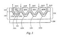
- FIG. 3is a side cross-sectional view of an interface layer and a portion of a manifold layer, together forming a heat exchanger in accordance with the present invention, coupled to a heat-generating source, with the manifold layer having a piecewise curving bottom surface that extends into a plurality of the trenches that form the interface layer.
- FIG. 4is a perspective view of the manifold layer and the interface layer of FIG. 1 A.
- FIG. 5is a perspective view of the manifold layer of FIG. 4 .
- FIG. 6Ais a top cross-sectional view of the manifold layer and the interface layer of FIG. 4 , showing how the narrowing trenches of the interface layer align with the fingers and the solid portions of the manifold layer.
- FIG. 6Bis a top cross-sectional view of the manifold layer and the interface layer of FIG. 6A , showing flow paths for a cooling material.
- FIG. 7is a perspective view of the manifold layer and the interface layer of FIG. 6B , again showing a flow path.
- FIG. 8is a perspective view of the manifold layer of FIG. 4 , an intermediate layer, and the interface layer of FIG. 4 , together forming a heat exchanger in accordance with the present invention.
- FIG. 9is a side cross-sectional view of the heat exchanger of FIG. 8 , showing several flow paths.
- FIG. 10is a perspective view of a manifold layer of FIG. 4 , an intermediate layer, and the interface layer of FIG. 4 , together forming a heat exchanger in accordance with the present invention.
- FIG. 11is a side cross-sectional view of the heat exchanger of FIG. 10 , showing a flow path.
- FIG. 12Ais a top view of an interface layer in accordance with one embodiment of the present invention.
- FIG. 12Bis side cross-sectional view of the interface layer of FIG. 12A and a manifold layer aligned with the interface layer, in accordance with the present invention.
- FIG. 12Cis more detailed top view of the interface layer of FIG. 12 A.
- FIGS. 13A-Dshow the steps used to form an interface layer, in accordance with the present invention.
- FIG. 1Ais a side cross-sectional view of a portion of a heat exchanger 110 coupled to a heat-generating source 180 .
- the heat exchanger 110comprises a manifold layer 101 and an interface layer 105 .
- the manifold layer 101comprises a surface having a plurality of apertures 101 A-E and a plurality of solid portions 101 J-M.
- the interface layer 105comprises a plurality of narrowing trenches 105 A-D and is coupled at a bottom surface to the heat-generating source 180 .
- Each narrowing trenchis defined by a sloping sidewall, a substantially planar floor, and a second sloping sidewall.
- Each trenchis narrowing in that a cross-sectional area at an upper plane of a trench is larger than a cross-sectional area at a bottom plane of the trench, realized, for example, by sloping sidewalls.
- the plurality of apertures 101 A-E, the plurality of solid portions 101 J-M, and the narrowing trenches 105 A-Ddefine flow paths or channels that can accommodate the flow of a cooling material.
- the cooling materialcomprises a fluid, such as a liquid, a vapor, air, or any combination of these. Circulating the cooling material in a narrowing trench above the heat-generating source 180 will cool that heat-generating source 180 at an area below the narrowing trench.
- FIG. 1Bis the side cross-sectional view of the heat exchanger 110 and heat-generating source 180 depicted in FIG. 1 A.
- FIG. 1Bfurther illustrates a cooling material introduced into the apertures 101 B and 101 D and removed from the apertures 10 A, 101 C, and 101 E. Arrows in FIG. 1B indicate the direction of flow for the cooling material. The squiggly arrows show the path of heat from the heat-generating source 180 to the cooling material.
- a cooling materialis introduced into the apertures 101 B and 101 D by, for example, a pump (not shown) coupled to the apertures 101 B and 101 D.
- the cooling material introduced into the aperture 101 B on the flow path 120is divided into the flow paths 121 and 122 .
- That portion of the cooling material traveling along the flow path 121is channeled from the aperture 101 B, to the narrowing trench 105 A, and to the aperture 101 A.
- the cooling material traveling along the flow path 121absorbs the heat conducted by the interface layer 105 from the heat-generating source 180 to the cooling material substantially adjacent to the narrowing trench 105 A.
- the cooling material traveling along the flow path 121is then channeled to the aperture 101 A, carrying the absorbed heat away from the heat-generating source 180 , and thus cooling the heat-generating source 180 at a position substantially adjacent to the narrowing trench 105 A.
- That portion of the cooling material traveling along the flow path 122is channeled from the aperture 101 B, to the narrowing trench 105 B, and to the aperture 101 C, thus cooling the heat-generating source 180 at a location substantially adjacent to the narrowing trench 105 B.
- the cooling material traveling along the flow path 122combines with the cooling material traveling along a flow path 131 to form cooling material traveling out of the aperture 101 C along a flow path 130 .
- cooling material introduced into the aperture 101 D along a flow path 135is divided into flow paths 131 and 132 . That portion of the cooling material traveling along the flow path 131 is channeled from the aperture 101 D, to the narrowing trench 105 C, and to the aperture 101 C, thus cooling the heat-generating source 180 at a location substantially adjacent to the narrowing trench 105 C.
- the cooling material from the flow path 131is combined with the cooling material from the flow path 122 to form cooling material on a flow path 130 at the aperture 101 C.
- That portion of the cooling material traveling along the flow path 132is channeled from the aperture 101 D, to the narrowing trench 105 D, and to the aperture 101 E, thus cooling the heat-generating source 180 at a location substantially adjacent to the narrowing trench 105 D.
- the cooling material removed from the apertures 101 A, 101 C, and 101 Ecan be processed in many ways.
- the cooling materialcan removed from the heat exchanger 110 , or it can be re-cooled and reintroduced into the apertures 101 B and 101 D.
- the manifold layer 101can have many shapes useful for providing a cooling material to the apertures 101 B and 101 D and for removing the cooling material from the apertures 10 A, 101 C, and 101 E. It will be appreciated that the roles of the apertures can be reversed or assigned in different combinations.
- the apertures 10 A, 101 C, and 101 Ecan be used to introduce a cooling material into the channels formed by the narrowing trenches and the apertures 101 B and 101 D used to remove the cooling material from the channels formed by the narrowing trenches.
- the drawingsshow only five apertures 10 A-E and four narrowing trenches 105 A-D, fewer or more apertures and narrowing trenches can be formed in accordance with the present invention.
- the interface layer 105has a thermal conductivity sufficient to conduct heat generated at the heat-generating source 180 to the cooling material traveling along the fluid paths 121 , 122 , 131 , and 132 .
- the interface layer 105has a thermal conductivity of approximately 20 W/m-K or larger.
- the interface layercomprises a silicon material. It will be appreciated, however, that the interface layer 105 can comprise other materials, such as a metal, and can have a thermal conductivity smaller than 20 W/m-K.
- fluid paths channeled along sloping sidewalls, rounded corners, and other non-perpendicular edges in accordance with the present inventionhave advantages over channels having substantially perpendicular edges. Because sloping sidewalls provide a more uniform flow path than do right-angled sidewalls, there are fewer pressure drops along the flow path. Thus, a pump requires less energy to transmit the cooling material along the channels and thus forms part of a more efficient heat-exchanging system.
- FIG. 2is a side cross-sectional view of a heat exchanger 210 , in accordance with the present invention, coupled to a heat-generating source 280 .
- the heat-exchanger 210comprises the interface layer 105 of FIG. 1A and a manifold layer 201 comprising a plurality of apertures 201 A-E and a plurality of solid portions 201 J-M.
- FIG. 2also depicts a flow path 220 from the aperture 201 B, divided into a flow path 221 to the aperture 201 A and a flow path 222 to the aperture 201 C.
- a flow path 235 from the aperture 201 Dis divided into the flow paths 231 and 232 .
- the flow path 231is combined with the flow path 222 to form a flow path 230 at the aperture 201 C.
- the flow path 232extends to the aperture 201 E.
- a bottom surface of the solid portion 201 J that forms part of the flow path 221extends into the narrowing trench 205 A and substantially conforms to the contour of the narrowing trench 205 A.
- the bottom surface of the solid portion 201 Jthus has a non-perpendicular and preferably rounded surface that forms part of the flow path 221 .
- This configurationis expected to enhance the fluid flow of the cooling material at the bottom of each narrowing trench 105 A, 105 B, 105 C, and 105 D, thereby enhancing the heat removal while reducing the pressure drops.
- a bottom surface of the solid portions 201 K-M, forming part of the flow paths 222 , 231 , and 232 , respectively,have similar contours.
- FIG. 3illustrates a cross-sectional diagram of a heat exchanger 250 , in accordance with the present invention, coupled to the heat-generating source 280 .
- the heat exchanger 250comprises the interface layer 105 described above and a manifold layer 265 having apertures 265 A-E and solid portions 265 J-M.
- FIG. 3also shows an exemplary flow path 261 from the aperture 265 B to the aperture 265 A.
- the solid portions 265 J-Meach has a bottom surface that extends into each of the plurality of narrowing trenches 105 A-D, respectively.
- the solid portion 265 Jis exemplary. As illustrated in FIG. 3 , the bottom surface of the solid portion 265 J is formed from piecewise straight edges, such as exemplary piecewise straight edges 270 A-C, which extend into the narrowing trench 105 A. As described above, it will be appreciated that because the bottom surface of the solid portion 265 J extends into the narrowing trench 105 D, the flow path 261 has a smaller cross-sectional area than a corresponding flow path formed when the bottom surface of a solid portion does not extend into the narrowing channels. Thus, for example, the flow path 261 illustrated in FIG. 3 has a smaller cross-sectional area than the flow path 121 illustrated in FIG. 1 B.
- This structurehas several advantages. For example, a cooling material traveling along the exemplary fluid flow paths 221 ( FIG. 2 ) and 261 ( FIG. 3 ) do not encounter any sharp edges as they travel between apertures, cooling a heat-generating source, and thus travel with fewer pressure drops. These structures also reduce the volume of the channel (flow path) along which the cooling material is transmitted. Forcing the same amount of cooling material along each smaller channel increases the velocity of the cooling material, which will increase the rate at which heat is carried away from the heat-generating source 280 . Those skilled in the art will recognize other advantages with a manifold layer having a bottom surface that defines a portion of a channel, conforming to the shape of a narrowing trench.
- heat exchangers in accordance with the present inventioncan have non-symmetrical features. Specifically, it may be advantageous to have larger openings at the outlets than at the inlets to accommodate the volume expansion associated with the transition from liquid to liquid/vapor mixtures.
- the narrowing trenches 105 A-D( FIG. 1A ) can also have different shapes and dimensions. And rather than aligned in symmetrical rows, the narrowing trenches can be apportioned in any number between rows, can even be staggered, or can be positioned and distributed in any manner to fit the application at hand.
- FIG. 1A-B , 2 , and 3all depict a one-dimensional view of a heat exchanger with four narrowing trenches 105 A-D, it will be appreciated that a heat exchanger in accordance with the present invention can have fewer than or more than four trenches in a one-, two- or three-dimensional configuration.
- FIG. 4is a perspective view of a heat exchanger 300 with a plurality of narrowing trenches in a two-dimensional configuration, used to cool a heat-generating source (not shown). It is believed that using a large number of small narrowing trenches has advantages over using a small number of large narrowing trenches to cool a heat-generating source. It is believed that small narrowing trenches formed without any sharp angles advantageously reduce pressure drops associated with cooling materials transmitted through the heat exchanger, thus requiring less energy to pump the cooling material through the heat exchanger. It is also believed that the smaller narrowing trenches increase the surface-to-volume ratio of the cooling material to the surface of the heat-generating source, thus aiding in more efficiently cooling the heat-generating source.
- the heat exchanger 300comprises the manifold layer 101 and the interface layer 105 , both of FIG. 1A , but gives a more complete three-dimensional view of each.
- FIG. 1Aillustrates only a cross-sectional portion of the manifold layer 101 .
- FIG. 4illustrates the manifold layer 101 with a portion of a top, enclosing surface 189 cut away to expose elements of the manifold layer 101 , contained below the top surface 189 and described below.
- the interface layer 105comprises the narrowing trenches 105 A-D and narrowing trenches 106 A-D and 107 A-D.
- FIG. 4also shows a plane RR′SS′ perpendicular to the top surface 189 and described below in relation to FIG. 7 .
- the manifold layer 101comprises a first plurality of hollow fingers 196 A-B (collectively, 196 ), a second plurality of hollow fingers 190 A-C (collectively, 190 ), solid portions 11 J-M, a first reservoir 195 , a second reservoir 198 , inlet ports 197 A and 197 B coupled to the first reservoir 195 , and outlet ports 199 A and 199 B coupled to the second reservoir 198 .
- the hollow fingers 190 and 196all lie substantially in a single plane, parallel to a bottom surface of the manifold layer 101 .
- the hollow fingers 190 and 196are openings in the manifold layer 101 , providing communications path between a top surface of the manifold layer 101 and a bottom surface of the manifold layer 101 .
- the hollow fingers 196are coupled to the first reservoir 195 and thus to each other, and provide a flow (communication) path from the first reservoir 195 to a first portion of the bottom surface of the manifold layer 101 .
- a cooling materialcan flow from the inlet ports 197 A-B, to the first reservoir 195 , to the hollow fingers 196 , and through the bottom of the manifold layer 101 into the interface layer 105 .
- the hollow fingers 190are coupled to the second reservoir 198 and thus to each other, and provide a flow path from the interface layer 105 up through the bottom of the manifold layer 101 , and to the second reservoir 198 .
- a cooling materialcan flow from the inlet ports 197 A-B, through the hollow fingers 196 , down to the interface layer 105 , along a narrowing trench 105 D, back up to the hollow fingers 190 in the manifold layer 101 , and to the outlet ports 199 A-B.
- the hollow fingers 196are interwoven with the hollow fingers 190 in that the hollow fingers 196 are interdigitated with the hollow fingers 190 .
- the solid portions 101 J-Malternate with the hollow fingers 196 and the hollow fingers 190 .
- the solid portion 101 Mis between the hollow fingers 190 A and 196 A
- the solid portion 101 Lis between the hollow fingers 196 A and 190 B
- the solid portion 101 Kis between the hollow fingers 190 B and 196 B
- the solid portion 101 Jis between the hollow fingers 196 B and 190 C.
- the solid portions 101 J-Mthus provide structure for the manifold layer 101 .
- FIG. 5is a perspective view of the manifold layer 101 of FIG. 4 , with the top surface 189 ( FIG. 4 ) completely removed.
- manifold layers used in accordance with the present inventioncan have configurations different from those described here.
- the hollow fingers 190 A-Cneed not be coupled to each other by the reservoir 198
- the hollow fingers 196 A-Bneed not be coupled to each other by the reservoir 195 .
- the plurality of hollow fingers 190need not be interwoven with the plurality of hollow fingers 196 .
- Manifold layers with any number and combination of hollow fingerscan be used. Examples of manifold layers that can be used in accordance with the present invention are taught in co-pending U.S. patent application Ser. No. 10/439,635, filed on May 16, 2003, and titled “Method and Apparatus for Flexible Fluid Delivery for Cooling Desired Hot Spots in a Heat Producing Device,” which is hereby incorporated by reference.
- FIG. 6Ais a top cross-sectional view of the manifold layer 101 aligned over the interface layer 105 .
- the twodefine a plurality of apertures 101 A-E, as illustrated, for example, in FIG. 1 A.
- FIGS. 1AFor example, as illustrated in FIGS.
- the solid portion 101 Joverlies and spans a portion of the narrowing trench 105 D, defining the apertures 10 A and 101 B; the solid portion 101 K overlies and spans a portion of the narrowing trench 105 B, defining the apertures 101 B and 101 C; the solid portion 101 L overlies and spans a portion of the narrowing trench 105 C, defining the apertures 101 C and 101 D; and the solid portion 101 M overlies and spans a portion of the narrowing trench 105 D, defining the apertures 101 D and 101 E.
- FIG. 6Aalso illustrates the dashed line segment TT′ shown in FIG. 4 .
- FIG. 6Billustrates flow paths along the manifold layer 101 of FIG. 6A for the heat exchanger 300 shown in FIG. 4 .
- a cooling materialis introduced into the inlet ports 197 A-B by, for example, a pump (not shown).
- the cooling materialthen flows into the first reservoir 195 and then into the hollow finger 196 B.
- the cooling materialtravels along the hollow finger 196 B and down into the aperture 101 B along the flow path 120 .
- the cooling material traveling along the hollow finger 190 Cflows to the reservoir 198 and to the outlet ports 199 A-B. From here, the cooling material can be removed from the heat exchanger 300 or cooled and reintroduced to the inlet ports 197 A-B.
- the cooling material introduced to the inlet ports 197 A-Bcan and generally does travel along hollow fingers in addition to the hollow fingers 196 B and 190 C.
- the present discussionis limited to cooling material traveling along the hollow fingers 196 B and 190 C only to simplify the present description.
- the cooling materialcan and generally is introduced into apertures other than the aperture 101 B.
- the cooling materialcan and generally does travel along paths other than the flow path 121 , as illustrated in FIG. 6 B.
- the cooling material traveling along the flow path 120can be divided with a portion traveling along the flow path 122 , as illustrated in FIG. 1 B.
- the heat exchanger 300can also comprise an intermediate layer that determines which apertures the cooling material is introduced into, thus controlling the flow of cooling material above a heat-generating source.
- FIG. 7illustrates a section of the heat exchanger 300 of FIG. 4 , with the top surface 189 removed.
- FIG. 7shows that section of the heat exchanger 300 of FIG. 4 delimited by the plane RR′SS′ and containing the first reservoir 195 .
- the plane RR′SS′intersects the hollow fingers 190 , the hollow fingers 196 , the solid portions 101 J-M, and the narrowing trenches 105 A-D, all shown in FIG. 4 .
- FIG. 7is used to describe a three-dimensional flow path for a portion of a cooling material 103 .
- the cooling material 103is introduced into the inlet port 197 A, into the reservoir 195 , along the hollow finger 196 A, down to the aperture 101 D, along the flow path 132 through the narrowing trench 105 D, up to the aperture 101 E, and up through the hollow finger 190 A.
- the cooling materialthen flows in a direction out of and perpendicular to the page.
- the cooling materialthen flows into the second reservoir 198 and out one or both of the outlet ports 199 A and 199 B.
- the cooling materialabsorbs heat generated by the heat-generating source 180 and conducted by that portion of the interface layer 105 substantially adjacent to the narrowing trench 105 D.
- the cooling materialcarries the absorbed heat away from the heat-generating source 180 , thus cooling the heat-generating source 180 at a location adjacent to the narrowing trench 105 D.
- the cooling material circulating in the other narrowing trenches 105 A-Ccools the heat-generating source 180 in a similar manner at locations adjacent to the narrowing trenches 105 A-C.
- FIG. 8illustrates a heat exchanger 500 comprising the manifold layer 101 and interface layer 105 , both of FIG. 4 , with an intermediate layer 310 positioned between the manifold layer 101 and the interface layer 105 .
- FIG. 8shows the manifold layer with a portion of the top surface 189 cut away.
- the intermediate layer 310can be used, for example, to allow cooling material to flow only into those channels that are above hot spots and to prevent cooling material from flowing into those channels that are not above hot spots. Thus, less cooling material is required and less energy is required for a pump circulating the cooling material.
- the intermediate layer 310has a plurality of apertures 311 A-E, used to control the flow of the cooling material from the manifold layer 101 to the interface layer 105 . While FIG. 9 depicts one row of apertures 311 A-E, it will be appreciated that the intermediate layer 310 can and generally does contain more than one row of apertures. FIG. 9 depicts one row of apertures to simplify the present discussion. The use of the intermediate layer 310 in accordance with the present invention is described in relation to FIG. 9 .
- FIG. 9is a side cross-sectional view of a section of the manifold layer 101 , the intermediate layer 310 , and the interface layer 105 of FIG. 8 .
- the aperture 311 Ais positioned between the hollow finger 190 C and the narrowing trench 105 A;
- the aperture 311 Bis positioned between the hollow finger 196 B and the narrowing trenches 105 A and 105 B;
- the aperture 311 Cis positioned between the hollow finger 190 B and the narrowing trenches 105 B and 105 C;
- the aperture 311 Dis positioned between the hollow finger 196 A and the narrowing trenches 105 C and 105 D;
- the aperture 311 Eis positioned between the hollow finger 190 A and the narrowing trench 105 D.
- the cooling material traveling along the flow path 317 Bis introduced into the hollow finger 196 B and along the flow paths 316 A and 316 B.
- the cooling material traveling along the flow path 316 Atravels through the aperture 311 A and into the hollow finger 190 C.
- the cooling material traveling along the flow path 316 Btravels through the aperture 311 C and into the hollow finger 190 B.
- the cooling material traveling along the flow path 317 Dis introduced into the hollow finger 196 A and along the flow paths 316 C and 316 D.
- the cooling material traveling along the flow path 316 Ctravels through the aperture 311 C and into the hollow finger 190 B.
- the cooling material traveling along the flow path 316 Dtravels through the aperture 311 E and into the hollow finger 190 A.
- FIG. 10shows a heat exchanger 600 having the manifold layer 101 , the interface layer 105 , both of FIG. 8 , and an intermediate layer 314 positioned between the manifold layer 101 and the interface layer 105 .
- the intermediate layer 314is configured to allow cooling material to flow only along the flow path 316 D (FIG. 11 ).
- FIG. 10shows the manifold layer 101 with a portion of the top surface 189 cut away.
- the intermediate layer 314has the apertures 311 D and 311 E, but not the apertures 311 A-C as shown in FIG. 8 .
- the cooling materialis controlled to flow only along the flow path 316 D and not along the flow paths 316 A-C.
- Intermediate layerssuch as the intermediate layer 314 are useful, for example, when a heat-generating source (not shown) coupled to a bottom surface of the interface layer 105 has non-uniform heat-generating portions.
- the heat-generating sourceneeds to be cooled only below the narrowing trench 105 D and thus below the flow path 316 D.
- Intermediate layerssuch as that described here are taught, for example, in U.S. patent application Ser. No. 10/439,635, filed on May 16, 2003, and titled “Method and apparatus for Flexible Fluid Delivery for Cooling Desired Hot Spots in a Heat Producing Device,” incorporated by reference above.
- FIGS. 12A-Care used to show features of a portion of a heat exchanger 790 in accordance with one embodiment of the present invention.
- FIGS. 12A-Cshow, respectively, a top view of an interface layer 705 , a side cross-sectional view of a heat exchanger 790 formed from the interface layer 705 and a manifold layer 701 , and a more detailed top view of the interface layer 705 .
- FIG. 12Aillustrates that the interface layer 705 has top surface 707 and narrowing trenches 705 A and 705 B.
- the narrowing trench 705 Ahas a first vertical edge wall 711 delineated by the line AA′ and a second vertical edge wall 712 delineated by the line BB′.
- the line MM′bisects the interface layer 705 and is used below to describe features of the interface layer 705 .
- the narrowing trench 705 Acomprises two sloping sidewall sections 709 and 710 , each of which comprises two sloping sidewalls ( 709 A and 709 B, and 710 A and 710 B, respectively).
- FIG. 12Bis a cross-sectional view of the heat exchanger 790 , in accordance with one embodiment of the present invention.
- FIG. 12Billustrates a cross section of the interface layer 705 of FIG. 12A , taken along the line MM′, and a cross-section of the manifold layer 701 .
- the manifold layer 701comprises an aperture 701 A with a width W 1 and an aperture 701 B with a width W 2 .
- the narrowing trench 705 Ahas a height H measured from a point X on the top surface 707 of the narrowing trench 705 A to a point Y on a flat bottom surface 706 of the narrowing trench 705 A.
- the narrowing trench 705 Ahas a first sloping sidewall section 709 that extends from the point X to the point Y. Similarly, the narrowing trench 705 A has a second sloping sidewall section 710 that extends from a point X′ on the top surface 707 of the narrowing trench 705 A to a point Y′ on the bottom surface 706 .
- FIG. 12Bfurther illustrates that the sloping sidewall section 709 (and thus, as described below, each of the sidewalls 709 A and 709 B that form the sidewall section 709 ) makes an angle ⁇ 1 with the bottom surface 706 , measured clockwise from the bottom surface 706 .
- the sidewall section 710makes an angle ⁇ 2 with the bottom surface 706 , measured counterclockwise from the bottom surface 706 .
- both ⁇ 1 and ⁇ 2are between 0 degrees and 90 degrees.
- ⁇ 1equals ⁇ 2 .
- the sloping sidewall section 709( FIG. 12B ) is comprised of two sloping sidewalls 709 A and 709 B angled to each other. Each of the sloping sidewalls 709 A and 709 B makes the angle ⁇ 1 with the bottom surface 706 , measured clockwise from the bottom surface 706 .
- the sloping sidewall section 710( FIG. 12B ) is comprised of two sloping sidewalls 710 A and 710 B angled to each other. Each of the sidewalls 710 A and 710 B makes the angle ⁇ 2 with the bottom surface 706 , measured counterclockwise from the bottom surface 706 . As illustrated in FIG.
- the line MM′bisects the heat exchanger 790 , intersecting the sloping sidewall section 709 where the sloping sidewall 709 A meets the sidewall 709 B and where the sloping sidewall 710 A meets the sloping sidewall 710 B.
- the narrowing trench 705 Ahas a width G, the distance between the lines AA′ and BB′.
- the height His approximately 1 mm
- the widths W 1 and W 2are both approximately 200 ⁇ m
- the width Gis approximately 20 ⁇ m
- the length Eis approximately 2 mm
- the length Vis approximately 3.4 mm.
- Hcan be larger or smaller than 1 mm
- one or both of W 1 and W 2can be larger or smaller than 200 ⁇ m
- Gcan be larger or smaller than 20 ⁇ m
- Ecan be larger or smaller than 2 mm.
- the dimensions of the trench 705 Bcan differ from those of the trench 705 A; the dimensions of both are depicted as similar merely for ease of illustration.
- His chosen large enough to provide structure for the heat exchanger 790 and to withstand the heat generated by a heat-generating source coupled to the heat exchanger 790 .
- His also small enough to allow heat to radiate quickly and efficiently to a cooling material circulating in the channels of the heat exchanger 790 .
- the above valuesare chosen to provide aspect ratios for the narrowing trenches of 10:1 or larger. It will be appreciated, however, that the dimensions can also be chosen to provide depth:width aspect ratios smaller than 10:1.
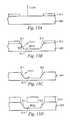
- FIGS. 13A-Ddepict steps used to fabricate a narrowing trench (and thus a channel) and a portion of a manifold layer, in accordance with one embodiment of the present invention. While FIGS. 13A-D depict the formation of one narrowing trench, it will be appreciated that by using appropriate masks, the steps illustrated in FIGS. 13A-D can be used to form a plurality of narrowing trenches in accordance with the present invention.
- FIG. 13Aillustrates a material 805 having a ⁇ 110> orientation with a mask 815 formed or deposited over a surface of the material 805 .
- the mask 815is patterned using, for example, photo-lithographic processes to expose areas that will later define the narrowing trenches.
- the material 805exhibits anisotropic etching, as described below.
- the material 805is ⁇ 110> oriented silicon. It will be appreciated that etching ⁇ 110> oriented silicon will expose ⁇ 111> oriented sidewalls of the silicon.
- the material 805is any orientation of silicon or any other material or composite of materials that together exhibit anisotropic etching.
- the material 805is then exposed to an etchant, such as a wet etchant, to expose the ⁇ 111> oriented planes (i.e., the sidewalls 811 and 812 ) and a bottom surface 813 , as illustrated in FIG. 13B , of the resulting narrowing trench 805 A.
- an etchantsuch as a wet etchant
- the material 805is etched in an anisotropic plasma etch.
- the sloping sidewall 811makes an angle ⁇ 3 , measured clockwise from the a bottom surface of the trench 805 A, of approximately 54.7 degrees.
- the present inventioncontemplates sidewalls having other angles with the bottom surface of the trench 805 A, angles preferably greater than 0 degrees but less than 90 degrees.
- the present inventionalso contemplates forming angled sidewalls within this range by, for example, combining piecewise sections to form an angled sidewall.
- the mask 815is formed of a material substantially resistant to the etchant.
- Etchants used in accordance with the present inventioninclude, but are not limited to, potassium hydroxide (KOH) and tetramethyl ammonium hydroxide (TMAH).
- KOHpotassium hydroxide
- TMAHtetramethyl ammonium hydroxide
- Masks used in accordance with the present inventioncan comprise nitrides, oxides such as SiO 2 , and some metals.
- a manifold layer 810is coupled to the interface layer 805 .
- the manifold layer 810can be coupled to the interface layer using a variety of techniques, including adhesive bonding, thermal fusing, anodic bonding, eutectic bonding, or other any other form of bonding.
- the manifold layer 810 and the interface layer 805can be formed from a single monolithic device during device fabrication.
- the manifold layer 810is formed and oriented so that the resulting apertures all lie substantially in a single plane, substantially parallel to the bottom surfaces of the narrowing trenches.
- the manifold layer 810can be formed from a variety of materials including, but not limited to, a plastic, a glass, a metal, a semiconductor, and a composite of materials.
- the interface layer 805can be coupled to a heat-generating source, such as a semiconductor device.
- the heat-generating sourcecan be integrally formed with a bottom surface of the interface layer 805 , for example in one or more semiconductor device fabrication steps.
- a pump(not shown) can then be coupled to the manifold layer 810 , as described above, to pump the cooling material through the heat exchanger and thus cool the heat-generating source.
- the cooling materialcan comprise a liquid, such as water, a gas, air, a vapor, or a combination of these.
- the interface layer 805can be manufactured from a metal, such as copper, using standard machining processes to form the narrowing trenches. These machining processes can include, but are not limited to, milling, sawing, drilling, stamping, EDM, wire EDM, coining, die casting, investment casting, or any combination of these. Alternatively, the interface layer 805 can be formed by other processes, including, but not limited to, electroplating, metal injection molding, LIGA processes, casting, or any combination of these.
- Heat exchangers in accordance with the present inventionprovide smooth flow paths (channels) in which cooling materials travel. Such structures work more efficiently and thus reduce the load on the pumps pumping the cooling material through the heat exchanger.
- the method of manufacturing heat exchangers in accordance with one embodiment of the present inventionare relatively inexpensive. Materials exhibiting anisotropic etching are chemically etched, preferably using wet chemistries, to form narrowing trenches that ultimately form the flow paths. The use of wet chemistries is inexpensive and quick compared to other device fabrication processes.
- the present inventioncan thus be used to inexpensively fabricate heat exchangers used to cool a variety of devices, such as semiconductor devices, motors, batteries, walls of process chambers, or any device that generates heat.
Landscapes
- Engineering & Computer Science (AREA)
- Physics & Mathematics (AREA)
- Thermal Sciences (AREA)
- Mechanical Engineering (AREA)
- General Engineering & Computer Science (AREA)
- General Physics & Mathematics (AREA)
- Condensed Matter Physics & Semiconductors (AREA)
- Manufacturing & Machinery (AREA)
- Computer Hardware Design (AREA)
- Microelectronics & Electronic Packaging (AREA)
- Power Engineering (AREA)
- Heat-Exchange Devices With Radiators And Conduit Assemblies (AREA)
- Cooling Or The Like Of Semiconductors Or Solid State Devices (AREA)
Abstract
Description
Claims (56)
Priority Applications (3)
| Application Number | Priority Date | Filing Date | Title |
|---|---|---|---|
| US10/643,684US7017654B2 (en) | 2003-03-17 | 2003-08-18 | Apparatus and method of forming channels in a heat-exchanging device |
| PCT/US2004/006771WO2004083759A2 (en) | 2003-03-17 | 2004-03-05 | Apparatus and method of forming channels in a heat-exchanging device |
| TW093106099ATWI296040B (en) | 2003-03-17 | 2004-03-08 | Apparatus and method of forming channels in a heat-exchanging device |
Applications Claiming Priority (2)
| Application Number | Priority Date | Filing Date | Title |
|---|---|---|---|
| US45572903P | 2003-03-17 | 2003-03-17 | |
| US10/643,684US7017654B2 (en) | 2003-03-17 | 2003-08-18 | Apparatus and method of forming channels in a heat-exchanging device |
Publications (2)
| Publication Number | Publication Date |
|---|---|
| US20040182560A1 US20040182560A1 (en) | 2004-09-23 |
| US7017654B2true US7017654B2 (en) | 2006-03-28 |
Family
ID=32994653
Family Applications (1)
| Application Number | Title | Priority Date | Filing Date |
|---|---|---|---|
| US10/643,684Expired - LifetimeUS7017654B2 (en) | 2003-03-17 | 2003-08-18 | Apparatus and method of forming channels in a heat-exchanging device |
Country Status (3)
| Country | Link |
|---|---|
| US (1) | US7017654B2 (en) |
| TW (1) | TWI296040B (en) |
| WO (1) | WO2004083759A2 (en) |
Cited By (61)
| Publication number | Priority date | Publication date | Assignee | Title |
|---|---|---|---|---|
| US20050063161A1 (en)* | 2003-09-18 | 2005-03-24 | Fuji Electric Systems Co., Ltd. | Heat sink and method for its production |
| US20050258468A1 (en)* | 2004-05-24 | 2005-11-24 | Texas Instruments, Incorporated | Dual work function metal gate integration in semiconductor devices |
| WO2006006170A3 (en)* | 2004-07-15 | 2006-08-31 | Yuval Yassour | Heat-exchanger device and cooling sysatem |
| US20060231237A1 (en)* | 2005-03-21 | 2006-10-19 | Carlos Dangelo | Apparatus and method for cooling ICs using nano-rod based chip-level heat sinks |
| US20060250773A1 (en)* | 2005-05-06 | 2006-11-09 | International Business Machines Corporation | Cooling apparatus, cooled electronic module and methods of fabrication thereof employing an integrated manifold and a plurality of thermally conductive fins |
| US20070168139A1 (en)* | 2004-09-16 | 2007-07-19 | Semiconductor Manufacturing International (Shanghai) Corporation | Device and method for voltage regulator with low standby current |
| US20080156519A1 (en)* | 2006-12-29 | 2008-07-03 | Bothhand Enterprise Inc. | Printed circuit boardc structure |
| US20080216991A1 (en)* | 2007-03-02 | 2008-09-11 | Hironori Oikawa | Cooling device for information equipment |
| US20080264604A1 (en)* | 2007-04-24 | 2008-10-30 | International Business Machines Corporation | Cooling appartaus, cooled electronic module and methods of fabrication employing a manifold structure with interleaved coolant inlet and outlet passageways |
| US20090046429A1 (en)* | 2007-08-07 | 2009-02-19 | Werner Douglas E | Deformable duct guides that accommodate electronic connection lines |
| US20090114373A1 (en)* | 2007-11-02 | 2009-05-07 | Calsonic Kansei Corporation | Heat exchanger |
| US20090225515A1 (en)* | 2008-03-10 | 2009-09-10 | James Hom | Thermal bus or junction for the removal of heat from electronic components |
| US7599184B2 (en) | 2006-02-16 | 2009-10-06 | Cooligy Inc. | Liquid cooling loops for server applications |
| US20100032143A1 (en)* | 2008-08-05 | 2010-02-11 | Cooligy Inc. | microheat exchanger for laser diode cooling |
| US20100038660A1 (en)* | 2008-08-13 | 2010-02-18 | Progressive Cooling Solutions, Inc. | Two-phase cooling for light-emitting devices |
| US7715194B2 (en) | 2006-04-11 | 2010-05-11 | Cooligy Inc. | Methodology of cooling multiple heat sources in a personal computer through the use of multiple fluid-based heat exchanging loops coupled via modular bus-type heat exchangers |
| US20100132404A1 (en)* | 2008-12-03 | 2010-06-03 | Progressive Cooling Solutions, Inc. | Bonds and method for forming bonds for a two-phase cooling apparatus |
| US7806168B2 (en) | 2002-11-01 | 2010-10-05 | Cooligy Inc | Optimal spreader system, device and method for fluid cooled micro-scaled heat exchange |
| US7814965B1 (en)* | 2005-10-27 | 2010-10-19 | United States Thermoelectric Consortium | Airflow heat dissipation device |
| US7836597B2 (en) | 2002-11-01 | 2010-11-23 | Cooligy Inc. | Method of fabricating high surface to volume ratio structures and their integration in microheat exchangers for liquid cooling system |
| US7913719B2 (en) | 2006-01-30 | 2011-03-29 | Cooligy Inc. | Tape-wrapped multilayer tubing and methods for making the same |
| US20110109335A1 (en)* | 2009-11-06 | 2011-05-12 | Schroeder Christopher R | Direct liquid-contact micro-channel heat transfer devices, methods of temperature control for semiconductive devices, and processes of forming same |
| US20110232864A1 (en)* | 2010-03-29 | 2011-09-29 | Zaffetti Mark A | Compact two sided cold plate with threaded inserts |
| US20110232882A1 (en)* | 2010-03-29 | 2011-09-29 | Zaffetti Mark A | Compact cold plate configuration utilizing ramped closure bars |
| US20110232866A1 (en)* | 2010-03-29 | 2011-09-29 | Zaffetti Mark A | Integral cold plate and honeycomb facesheet assembly |
| US20110232879A1 (en)* | 2010-03-29 | 2011-09-29 | Zaffetti Mark A | Compact two sided cold plate with transfer tubes |
| US8077460B1 (en) | 2010-07-19 | 2011-12-13 | Toyota Motor Engineering & Manufacturing North America, Inc. | Heat exchanger fluid distribution manifolds and power electronics modules incorporating the same |
| US8157001B2 (en) | 2006-03-30 | 2012-04-17 | Cooligy Inc. | Integrated liquid to air conduction module |
| US8199505B2 (en) | 2010-09-13 | 2012-06-12 | Toyota Motor Engineering & Manufacturing Norh America, Inc. | Jet impingement heat exchanger apparatuses and power electronics modules |
| US8210243B2 (en) | 2008-07-21 | 2012-07-03 | International Business Machines Corporation | Structure and apparatus for cooling integrated circuits using cooper microchannels |
| US20130050944A1 (en)* | 2011-08-22 | 2013-02-28 | Mark Eugene Shepard | High performance liquid cooled heatsink for igbt modules |
| US8391008B2 (en) | 2011-02-17 | 2013-03-05 | Toyota Motor Engineering & Manufacturing North America, Inc. | Power electronics modules and power electronics module assemblies |
| US8427832B2 (en) | 2011-01-05 | 2013-04-23 | Toyota Motor Engineering & Manufacturing North America, Inc. | Cold plate assemblies and power electronics modules |
| US8464781B2 (en) | 2002-11-01 | 2013-06-18 | Cooligy Inc. | Cooling systems incorporating heat exchangers and thermoelectric layers |
| US8482919B2 (en) | 2011-04-11 | 2013-07-09 | Toyota Motor Engineering & Manufacturing North America, Inc. | Power electronics card assemblies, power electronics modules, and power electronics devices |
| US8602092B2 (en) | 2003-07-23 | 2013-12-10 | Cooligy, Inc. | Pump and fan control concepts in a cooling system |
| US8659896B2 (en) | 2010-09-13 | 2014-02-25 | Toyota Motor Engineering & Manufacturing North America, Inc. | Cooling apparatuses and power electronics modules |
| US8786078B1 (en) | 2013-01-04 | 2014-07-22 | Toyota Motor Engineering & Manufacturing North America, Inc. | Vehicles, power electronics modules and cooling apparatuses with single-phase and two-phase surface enhancement features |
| US8797741B2 (en)* | 2010-10-21 | 2014-08-05 | Raytheon Company | Maintaining thermal uniformity in micro-channel cold plates with two-phase flows |
| US9131631B2 (en) | 2013-08-08 | 2015-09-08 | Toyota Motor Engineering & Manufacturing North America, Inc. | Jet impingement cooling apparatuses having enhanced heat transfer assemblies |
| CN105318621A (en)* | 2014-07-29 | 2016-02-10 | 英特尔公司 | Fluid flow channel for enhanced heat transfer efficiency |
| US20160290734A1 (en)* | 2015-03-30 | 2016-10-06 | Infinera Corporation | Low-cost nano-heat pipe |
| US9510478B2 (en) | 2013-06-20 | 2016-11-29 | Honeywell International Inc. | Cooling device including etched lateral microchannels |
| US9655294B2 (en) | 2010-07-28 | 2017-05-16 | Wolverine Tube, Inc. | Method of producing electronics substrate with enhanced direct bonded metal |
| US9681580B2 (en) | 2010-07-28 | 2017-06-13 | Wolverine Tube, Inc. | Method of producing an enhanced base plate |
| US9795057B2 (en) | 2010-07-28 | 2017-10-17 | Wolverine Tube, Inc. | Method of producing a liquid cooled coldplate |
| US10211127B1 (en)* | 2016-03-28 | 2019-02-19 | Lockheed Martin Corporation | Integration of chip level micro-fluidic cooling in chip packages for heat flux removal |
| US10270220B1 (en)* | 2013-03-13 | 2019-04-23 | Science Research Laboratory, Inc. | Methods and systems for heat flux heat removal |
| US10490482B1 (en)* | 2018-12-05 | 2019-11-26 | Toyota Motor Engineering & Manufacturing North America, Inc. | Cooling devices including jet cooling with an intermediate mesh and methods for using the same |
| US10531594B2 (en) | 2010-07-28 | 2020-01-07 | Wieland Microcool, Llc | Method of producing a liquid cooled coldplate |
| US10533809B1 (en)* | 2018-07-06 | 2020-01-14 | Keysight Technologies, Inc. | Cooling apparatus and methods of use |
| US20220013386A1 (en)* | 2020-07-08 | 2022-01-13 | Applied Materials, Inc. | Annealing chamber |
| US20230200009A1 (en)* | 2021-12-22 | 2023-06-22 | Baidu Usa Llc | Two phase immersion system with local fluid accelerations |
| US20230284414A1 (en)* | 2022-03-04 | 2023-09-07 | Aavid Thermalloy, Llc | Liquid cooled heat exchanger |
| US20230301019A1 (en)* | 2022-03-18 | 2023-09-21 | Baidu Usa Llc | System on a chip based cooling system |
| US20230380106A1 (en)* | 2022-05-19 | 2023-11-23 | Toyota Motor Engineering & Manufacturing North America, Inc. | Systems for cooler devices and cooling manifolds |
| US20230392836A1 (en)* | 2020-12-02 | 2023-12-07 | Danfoss A/S | Motor cooling using impingement jets created by perforated cooling jacket |
| US20230417227A1 (en)* | 2022-06-25 | 2023-12-28 | EvansWerks, Inc. | Pumping systems and methods |
| US11894251B2 (en) | 2018-10-04 | 2024-02-06 | Applied Materials, Inc. | Transport system |
| US12141508B2 (en) | 2020-03-16 | 2024-11-12 | Washington University | Systems and methods for forming micropillar array |
| US12363864B2 (en) | 2022-06-25 | 2025-07-15 | EvansWerks, Inc. | Cooling system and methods |
Families Citing this family (26)
| Publication number | Priority date | Publication date | Assignee | Title |
|---|---|---|---|---|
| DE102005058780A1 (en) | 2005-12-09 | 2007-06-14 | Forschungszentrum Karlsruhe Gmbh | Micro heat exchanger and the use thereof as a fluid cooler for electronic components |
| US7331378B2 (en)* | 2006-01-17 | 2008-02-19 | Delphi Technologies, Inc. | Microchannel heat sink |
| JP2009533859A (en)* | 2006-04-13 | 2009-09-17 | コーニンクレッカ フィリップス エレクトロニクス エヌ ヴィ | Microdevice with microtube |
| US9453691B2 (en) | 2007-08-09 | 2016-09-27 | Coolit Systems, Inc. | Fluid heat exchange systems |
| US8746330B2 (en) | 2007-08-09 | 2014-06-10 | Coolit Systems Inc. | Fluid heat exchanger configured to provide a split flow |
| EP2149771B8 (en)* | 2008-07-29 | 2017-03-15 | MAHLE Behr GmbH & Co. KG | Device for cooling a heat source of a motor vehicle |
| CN101929819A (en)* | 2009-06-26 | 2010-12-29 | 富准精密工业(深圳)有限公司 | Flat-plate heat pipe |
| WO2012069054A1 (en)* | 2010-11-25 | 2012-05-31 | Danfoss Drives A/S | An energy transfer device |
| US10365667B2 (en) | 2011-08-11 | 2019-07-30 | Coolit Systems, Inc. | Flow-path controllers and related systems |
| US12366870B2 (en) | 2013-03-15 | 2025-07-22 | Coolit Systems, Inc. | Flow-path controllers and related systems |
| US10364809B2 (en) | 2013-03-15 | 2019-07-30 | Coolit Systems, Inc. | Sensors, multiplexed communication techniques, and related systems |
| DE102013109246B4 (en) | 2013-08-27 | 2019-01-31 | Rogers Germany Gmbh | Cooling arrangement and arrangement with it |
| JP6439326B2 (en) | 2014-08-29 | 2018-12-19 | 株式会社Ihi | Reactor |
| US10415597B2 (en) | 2014-10-27 | 2019-09-17 | Coolit Systems, Inc. | Fluid heat exchange systems |
| US11480398B2 (en)* | 2015-05-22 | 2022-10-25 | The Johns Hopkins University | Combining complex flow manifold with three dimensional woven lattices as a thermal management unit |
| CN107872942B (en)* | 2016-09-27 | 2019-09-20 | 技嘉科技股份有限公司 | Heat exchange device and method for manufacturing the same |
| US11948860B2 (en)* | 2017-08-29 | 2024-04-02 | Welcon Inc. | Heat sink |
| US11452243B2 (en) | 2017-10-12 | 2022-09-20 | Coolit Systems, Inc. | Cooling system, controllers and methods |
| CN108168354B (en)* | 2018-01-29 | 2023-08-01 | 杭州中泰深冷技术股份有限公司 | Liquid injection structure and collecting and redistributing fin structure and method thereof |
| WO2020123631A1 (en)* | 2018-12-11 | 2020-06-18 | Kelvin Thermal Technologies, Inc. | Vapor chamber |
| US11662037B2 (en) | 2019-01-18 | 2023-05-30 | Coolit Systems, Inc. | Fluid flow control valve for fluid flow systems, and methods |
| US11473860B2 (en) | 2019-04-25 | 2022-10-18 | Coolit Systems, Inc. | Cooling module with leak detector and related systems |
| US11387164B2 (en)* | 2019-08-28 | 2022-07-12 | Taiwan Semiconductor Manufacturing Company, Ltd. | Semiconductor device and manufacturing method thereof |
| WO2021229365A1 (en) | 2020-05-11 | 2021-11-18 | Coolit Systems, Inc. | Liquid pumping units, and related systems and methods |
| US11725886B2 (en) | 2021-05-20 | 2023-08-15 | Coolit Systems, Inc. | Modular fluid heat exchange systems |
| US12200914B2 (en) | 2022-01-24 | 2025-01-14 | Coolit Systems, Inc. | Smart components, systems and methods for transferring heat |
Citations (236)
| Publication number | Priority date | Publication date | Assignee | Title |
|---|---|---|---|---|
| US596062A (en) | 1897-12-28 | Device for preventing bursting of freezing pipes | ||
| US2039593A (en) | 1935-06-20 | 1936-05-05 | Theodore N Hubbuch | Heat transfer coil |
| US2273505A (en) | 1942-02-17 | Container | ||
| US3361195A (en) | 1966-09-23 | 1968-01-02 | Westinghouse Electric Corp | Heat sink member for a semiconductor device |
| US3654988A (en) | 1970-02-24 | 1972-04-11 | American Standard Inc | Freeze protection for outdoor cooler |
| US3771219A (en) | 1970-02-05 | 1973-11-13 | Sharp Kk | Method for manufacturing semiconductor device |
| US3817321A (en) | 1971-01-19 | 1974-06-18 | Bosch Gmbh Robert | Cooling apparatus semiconductor elements, comprising partitioned bubble pump, separator and condenser means |
| US3823572A (en) | 1973-08-15 | 1974-07-16 | American Air Filter Co | Freeze protection device in heat pump system |
| US3923426A (en) | 1974-08-15 | 1975-12-02 | Alza Corp | Electroosmotic pump and fluid dispenser including same |
| US3929154A (en) | 1974-07-29 | 1975-12-30 | Frank E Goodwin | Freeze protection apparatus |
| US3948316A (en) | 1973-02-06 | 1976-04-06 | Gaz De France | Process of and device for using the energy given off by a heat source |
| US4109707A (en) | 1975-07-02 | 1978-08-29 | Honeywell Information Systems, Inc. | Fluid cooling systems for electronic systems |
| US4138996A (en) | 1977-07-28 | 1979-02-13 | Rheem Manufacturing Company | Solar heater freeze protection system |
| US4194559A (en) | 1978-11-01 | 1980-03-25 | Thermacore, Inc. | Freeze accommodating heat pipe |
| US4211208A (en) | 1976-12-24 | 1980-07-08 | Deutsche Forschungs- Und Versuchsanstalt Fur Luft- Und Raumfahrt E.V. | Container for a heat storage medium |
| US4248295A (en) | 1980-01-17 | 1981-02-03 | Thermacore, Inc. | Freezable heat pipe |
| US4312012A (en) | 1977-11-25 | 1982-01-19 | International Business Machines Corp. | Nucleate boiling surface for increasing the heat transfer from a silicon device to a liquid coolant |
| US4450472A (en) | 1981-03-02 | 1984-05-22 | The Board Of Trustees Of The Leland Stanford Junior University | Method and means for improved heat removal in compact semiconductor integrated circuits and similar devices utilizing coolant chambers and microscopic channels |
| US4467861A (en) | 1982-10-04 | 1984-08-28 | Otdel Fiziko-Tekhnicheskikh Problem Energetiki Uralskogo Nauchnogo Tsentra Akademii Nauk Sssr | Heat-transporting device |
| US4485429A (en) | 1982-06-09 | 1984-11-27 | Sperry Corporation | Apparatus for cooling integrated circuit chips |
| US4516632A (en) | 1982-08-31 | 1985-05-14 | The United States Of America As Represented By The United States Deparment Of Energy | Microchannel crossflow fluid heat exchanger and method for its fabrication |
| US4540115A (en) | 1983-08-26 | 1985-09-10 | Rca Corporation | Flux-free photodetector bonding |
| US4561040A (en) | 1984-07-12 | 1985-12-24 | Ibm Corporation | Cooling system for VLSI circuit chips |
| US4567505A (en) | 1983-10-27 | 1986-01-28 | The Board Of Trustees Of The Leland Stanford Junior University | Heat sink and method of attaching heat sink to a semiconductor integrated circuit and the like |
| US4573067A (en) | 1981-03-02 | 1986-02-25 | The Board Of Trustees Of The Leland Stanford Junior University | Method and means for improved heat removal in compact semiconductor integrated circuits |
| US4574876A (en) | 1981-05-11 | 1986-03-11 | Extracorporeal Medical Specialties, Inc. | Container with tapered walls for heating or cooling fluids |
| US4644385A (en) | 1983-10-28 | 1987-02-17 | Hitachi, Ltd. | Cooling module for integrated circuit chips |
| US4664181A (en) | 1984-03-05 | 1987-05-12 | Thermo Electron Corporation | Protection of heat pipes from freeze damage |
| US4758926A (en) | 1986-03-31 | 1988-07-19 | Microelectronics And Computer Technology Corporation | Fluid-cooled integrated circuit package |
| US4866570A (en) | 1988-08-05 | 1989-09-12 | Ncr Corporation | Apparatus and method for cooling an electronic device |
| US4868712A (en) | 1987-02-04 | 1989-09-19 | Woodman John K | Three dimensional integrated circuit package |
| JPH01256775A (en) | 1988-04-04 | 1989-10-13 | Mitsubishi Electric Corp | Pod cooling device |
| US4893174A (en) | 1985-07-08 | 1990-01-09 | Hitachi, Ltd. | High density integration of semiconductor circuit |
| US4894709A (en) | 1988-03-09 | 1990-01-16 | Massachusetts Institute Of Technology | Forced-convection, liquid-cooled, microchannel heat sinks |
| US4896719A (en) | 1988-05-11 | 1990-01-30 | Mcdonnell Douglas Corporation | Isothermal panel and plenum |
| US4903761A (en) | 1987-06-03 | 1990-02-27 | Lockheed Missiles & Space Company, Inc. | Wick assembly for self-regulated fluid management in a pumped two-phase heat transfer system |
| US4908112A (en) | 1988-06-16 | 1990-03-13 | E. I. Du Pont De Nemours & Co. | Silicon semiconductor wafer for analyzing micronic biological samples |
| US4938280A (en) | 1988-11-07 | 1990-07-03 | Clark William E | Liquid-cooled, flat plate heat exchanger |
| US5009760A (en) | 1989-07-28 | 1991-04-23 | Board Of Trustees Of The Leland Stanford Junior University | System for measuring electrokinetic properties and for characterizing electrokinetic separations by monitoring current in electrophoresis |
| US5016090A (en)* | 1990-03-21 | 1991-05-14 | International Business Machines Corporation | Cross-hatch flow distribution and applications thereof |
| US5016138A (en) | 1987-10-27 | 1991-05-14 | Woodman John K | Three dimensional integrated circuit package |
| US5043797A (en) | 1990-04-03 | 1991-08-27 | General Electric Company | Cooling header connection for a thyristor stack |
| US5057908A (en) | 1990-07-10 | 1991-10-15 | Iowa State University Research Foundation, Inc. | High power semiconductor device with integral heat sink |
| US5058627A (en) | 1989-04-10 | 1991-10-22 | Brannen Wiley W | Freeze protection system for water pipes |
| US5070040A (en) | 1990-03-09 | 1991-12-03 | University Of Colorado Foundation, Inc. | Method and apparatus for semiconductor circuit chip cooling |
| US5083194A (en) | 1990-01-16 | 1992-01-21 | Cray Research, Inc. | Air jet impingement on miniature pin-fin heat sinks for cooling electronic components |
| US5088005A (en) | 1990-05-08 | 1992-02-11 | Sundstrand Corporation | Cold plate for cooling electronics |
| US5096388A (en) | 1990-03-22 | 1992-03-17 | The Charles Stark Draper Laboratory, Inc. | Microfabricated pump |
| US5099311A (en) | 1991-01-17 | 1992-03-24 | The United States Of America As Represented By The United States Department Of Energy | Microchannel heat sink assembly |
| US5099910A (en) | 1991-01-15 | 1992-03-31 | Massachusetts Institute Of Technology | Microchannel heat sink with alternating flow directions |
| US5125451A (en) | 1991-04-02 | 1992-06-30 | Microunity Systems Engineering, Inc. | Heat exchanger for solid-state electronic devices |
| US5131233A (en) | 1991-03-08 | 1992-07-21 | Cray Computer Corporation | Gas-liquid forced turbulence cooling |
| US5161089A (en) | 1990-06-04 | 1992-11-03 | International Business Machines Corporation | Enhanced multichip module cooling with thermally optimized pistons and closely coupled convective cooling channels, and methods of manufacturing the same |
| US5179500A (en) | 1990-02-27 | 1993-01-12 | Grumman Aerospace Corporation | Vapor chamber cooled electronic circuit card |
| US5203401A (en) | 1990-06-29 | 1993-04-20 | Digital Equipment Corporation | Wet micro-channel wafer chuck and cooling method |
| US5218515A (en) | 1992-03-13 | 1993-06-08 | The United States Of America As Represented By The United States Department Of Energy | Microchannel cooling of face down bonded chips |
| US5219278A (en) | 1989-11-10 | 1993-06-15 | Westonbridge International, Ltd. | Micropump with improved priming |
| US5228502A (en)* | 1991-09-04 | 1993-07-20 | International Business Machines Corporation | Cooling by use of multiple parallel convective surfaces |
| US5232047A (en) | 1991-04-02 | 1993-08-03 | Microunity Systems Engineering, Inc. | Heat exchanger for solid-state electronic devices |
| US5239200A (en) | 1991-08-21 | 1993-08-24 | International Business Machines Corporation | Apparatus for cooling integrated circuit chips |
| US5239443A (en)* | 1992-04-23 | 1993-08-24 | International Business Machines Corporation | Blind hole cold plate cooling system |
| US5263251A (en) | 1991-04-02 | 1993-11-23 | Microunity Systems Engineering | Method of fabricating a heat exchanger for solid-state electronic devices |
| US5265670A (en) | 1990-04-27 | 1993-11-30 | International Business Machines Corporation | Convection transfer system |
| US5269372A (en)* | 1992-12-21 | 1993-12-14 | International Business Machines Corporation | Intersecting flow network for a cold plate cooling system |
| US5275237A (en) | 1992-06-12 | 1994-01-04 | Micron Technology, Inc. | Liquid filled hot plate for precise temperature control |
| US5308429A (en) | 1992-09-29 | 1994-05-03 | Digital Equipment Corporation | System for bonding a heatsink to a semiconductor chip package |
| US5309319A (en) | 1991-02-04 | 1994-05-03 | International Business Machines Corporation | Integral cooling system for electric components |
| US5316077A (en) | 1992-12-09 | 1994-05-31 | Eaton Corporation | Heat sink for electrical circuit components |
| US5317805A (en) | 1992-04-28 | 1994-06-07 | Minnesota Mining And Manufacturing Company | Method of making microchanneled heat exchangers utilizing sacrificial cores |
| US5325265A (en) | 1988-11-10 | 1994-06-28 | Mcnc | High performance integrated circuit chip package |
| US5336062A (en) | 1990-02-27 | 1994-08-09 | Fraunhofer-Gesellschaft Zur Forderung Der Angewandten Forschung E.V. | Microminiaturized pump |
| US5346000A (en) | 1992-11-28 | 1994-09-13 | Erno Raumfahrttechnik Gmbh | Heat pipe with a bubble trap |
| US5380956A (en) | 1993-07-06 | 1995-01-10 | Sun Microsystems, Inc. | Multi-chip cooling module and method |
| US5383340A (en) | 1994-03-24 | 1995-01-24 | Aavid Laboratories, Inc. | Two-phase cooling system for laptop computers |
| US5386143A (en) | 1991-10-25 | 1995-01-31 | Digital Equipment Corporation | High performance substrate, electronic package and integrated circuit cooling process |
| US5388635A (en)* | 1990-04-27 | 1995-02-14 | International Business Machines Corporation | Compliant fluidic coolant hat |
| US5421943A (en) | 1991-11-22 | 1995-06-06 | International Business Machines Corporation | Pulsed current resistive heating for bonding temperature critical components |
| US5427174A (en) | 1993-04-30 | 1995-06-27 | Heat Transfer Devices, Inc. | Method and apparatus for a self contained heat exchanger |
| US5436793A (en) | 1993-03-31 | 1995-07-25 | Ncr Corporation | Apparatus for containing and cooling an integrated circuit device having a thermally insulative positioning member |
| US5459099A (en) | 1990-09-28 | 1995-10-17 | The United States Of America As Represented By The Secretary Of The Navy | Method of fabricating sub-half-micron trenches and holes |
| US5490117A (en) | 1993-03-23 | 1996-02-06 | Seiko Epson Corporation | IC card with dual level power supply interface and method for operating the IC card |
| US5508234A (en) | 1994-10-31 | 1996-04-16 | International Business Machines Corporation | Microcavity structures, fabrication processes, and applications thereof |
| US5514906A (en) | 1993-11-10 | 1996-05-07 | Fujitsu Limited | Apparatus for cooling semiconductor chips in multichip modules |
| US5544696A (en) | 1994-07-01 | 1996-08-13 | The United States Of America As Represented By The Secretary Of The Air Force | Enhanced nucleate boiling heat transfer for electronic cooling and thermal energy transfer |
| US5548605A (en)* | 1995-05-15 | 1996-08-20 | The Regents Of The University Of California | Monolithic microchannel heatsink |
| US5575929A (en) | 1995-06-05 | 1996-11-19 | The Regents Of The University Of California | Method for making circular tubular channels with two silicon wafers |
| US5579828A (en) | 1996-01-16 | 1996-12-03 | Hudson Products Corporation | Flexible insert for heat pipe freeze protection |
| US5585069A (en) | 1994-11-10 | 1996-12-17 | David Sarnoff Research Center, Inc. | Partitioned microelectronic and fluidic device array for clinical diagnostics and chemical synthesis |
| US5641400A (en) | 1994-10-19 | 1997-06-24 | Hewlett-Packard Company | Use of temperature control devices in miniaturized planar column devices and miniaturized total analysis systems |
| US5658831A (en) | 1993-03-31 | 1997-08-19 | Unisys Corporation | Method of fabricating an integrated circuit package having a liquid metal-aluminum/copper joint |
| US5675473A (en) | 1996-02-23 | 1997-10-07 | Motorola, Inc. | Apparatus and method for shielding an electronic module from electromagnetic radiation |
| US5692558A (en) | 1996-07-22 | 1997-12-02 | Northrop Grumman Corporation | Microchannel cooling using aviation fuels for airborne electronics |
| US5696405A (en) | 1995-10-13 | 1997-12-09 | Lucent Technologies Inc. | Microelectronic package with device cooling |
| US5703536A (en) | 1996-04-08 | 1997-12-30 | Harris Corporation | Liquid cooling system for high power solid state AM transmitter |
| US5704416A (en) | 1993-09-10 | 1998-01-06 | Aavid Laboratories, Inc. | Two phase component cooler |
| US5727618A (en) | 1993-08-23 | 1998-03-17 | Sdl Inc | Modular microchannel heat exchanger |
| US5740013A (en) | 1996-07-03 | 1998-04-14 | Hewlett-Packard Company | Electronic device enclosure having electromagnetic energy containment and heat removal characteristics |
| JPH1099592A (en) | 1996-09-27 | 1998-04-21 | Matsushita Electric Ind Co Ltd | Pump equipment for washing machines, etc. |
| US5759014A (en) | 1994-01-14 | 1998-06-02 | Westonbridge International Limited | Micropump |
| US5763951A (en) | 1996-07-22 | 1998-06-09 | Northrop Grumman Corporation | Non-mechanical magnetic pump for liquid cooling |
| US5768104A (en) | 1996-02-22 | 1998-06-16 | Cray Research, Inc. | Cooling approach for high power integrated circuits mounted on printed circuit boards |
| US5774779A (en) | 1996-11-06 | 1998-06-30 | Materials And Electrochemical Research (Mer) Corporation | Multi-channel structures and processes for making such structures |
| US5801442A (en) | 1996-07-22 | 1998-09-01 | Northrop Grumman Corporation | Microchannel cooling of high power semiconductor devices |
| US5800690A (en) | 1996-07-03 | 1998-09-01 | Caliper Technologies Corporation | Variable control of electroosmotic and/or electrophoretic forces within a fluid-containing structure via electrical forces |
| US5835345A (en) | 1996-10-02 | 1998-11-10 | Sdl, Inc. | Cooler for removing heat from a heated region |
| US5836750A (en) | 1997-10-09 | 1998-11-17 | Honeywell Inc. | Electrostatically actuated mesopump having a plurality of elementary cells |
| US5858188A (en) | 1990-02-28 | 1999-01-12 | Aclara Biosciences, Inc. | Acrylic microchannels and their use in electrophoretic applications |
| US5869004A (en) | 1997-06-09 | 1999-02-09 | Caliper Technologies Corp. | Methods and apparatus for in situ concentration and/or dilution of materials in microfluidic systems |
| US5870823A (en) | 1996-11-27 | 1999-02-16 | International Business Machines Corporation | Method of forming a multilayer electronic packaging substrate with integral cooling channels |
| US5874795A (en) | 1995-12-28 | 1999-02-23 | Japan Servo Co., Ltd | Multi-phase permanent-magnet type electric rotating machine |
| US5876655A (en) | 1995-02-21 | 1999-03-02 | E. I. Du Pont De Nemours And Company | Method for eliminating flow wrinkles in compression molded panels |
| US5880017A (en) | 1994-08-08 | 1999-03-09 | Hewlett-Packard Co. | Method of bumping substrates by contained paste deposition |
| US5880524A (en) | 1997-05-05 | 1999-03-09 | Intel Corporation | Heat pipe lid for electronic packages |
| US5901037A (en) | 1997-06-18 | 1999-05-04 | Northrop Grumman Corporation | Closed loop liquid cooling for semiconductor RF amplifier modules |
| US5921087A (en) | 1997-04-22 | 1999-07-13 | Intel Corporation | Method and apparatus for cooling integrated circuits using a thermoelectric module |
| US5936192A (en) | 1996-12-20 | 1999-08-10 | Aisin Seiki Kabushiki Kaisha | Multi-stage electronic cooling device |
| US5940270A (en) | 1998-07-08 | 1999-08-17 | Puckett; John Christopher | Two-phase constant-pressure closed-loop water cooling system for a heat producing device |
| US5942093A (en) | 1997-06-18 | 1999-08-24 | Sandia Corporation | Electro-osmotically driven liquid delivery method and apparatus |
| US5945217A (en) | 1997-10-14 | 1999-08-31 | Gore Enterprise Holdings, Inc. | Thermally conductive polytrafluoroethylene article |
| US5965813A (en) | 1998-07-23 | 1999-10-12 | Industry Technology Research Institute | Integrated flow sensor |
| US5964092A (en) | 1996-12-13 | 1999-10-12 | Nippon Sigmax, Co., Ltd. | Electronic cooling apparatus |
| US5978220A (en) | 1996-10-23 | 1999-11-02 | Asea Brown Boveri Ag | Liquid cooling device for a high-power semiconductor module |
| US5993750A (en) | 1997-04-11 | 1999-11-30 | Eastman Kodak Company | Integrated ceramic micro-chemical plant |
| US5997713A (en) | 1997-05-08 | 1999-12-07 | Nanosciences Corporation | Silicon etching process for making microchannel plates |
| US6007309A (en) | 1995-12-13 | 1999-12-28 | Hartley; Frank T. | Micromachined peristaltic pumps |
| US6010316A (en) | 1996-01-16 | 2000-01-04 | The Board Of Trustees Of The Leland Stanford Junior University | Acoustic micropump |
| US6014312A (en) | 1997-03-17 | 2000-01-11 | Curamik Electronics Gmbh | Cooler or heat sink for electrical components or circuits and an electrical circuit with this heat sink |
| US6013164A (en) | 1997-06-25 | 2000-01-11 | Sandia Corporation | Electokinetic high pressure hydraulic system |
| US6019882A (en) | 1997-06-25 | 2000-02-01 | Sandia Corporation | Electrokinetic high pressure hydraulic system |
| US6019165A (en) | 1998-05-18 | 2000-02-01 | Batchelder; John Samuel | Heat exchange apparatus |
| US6034872A (en) | 1997-07-16 | 2000-03-07 | International Business Machines Corporation | Cooling computer systems |
| US6039114A (en) | 1996-01-04 | 2000-03-21 | Daimler - Benz Aktiengesellschaft | Cooling body having lugs |
| US6054034A (en) | 1990-02-28 | 2000-04-25 | Aclara Biosciences, Inc. | Acrylic microchannels and their use in electrophoretic applications |
| US6068752A (en) | 1997-04-25 | 2000-05-30 | Caliper Technologies Corp. | Microfluidic devices incorporating improved channel geometries |
| US6090251A (en) | 1997-06-06 | 2000-07-18 | Caliper Technologies, Inc. | Microfabricated structures for facilitating fluid introduction into microfluidic devices |
| US6096656A (en) | 1999-06-24 | 2000-08-01 | Sandia Corporation | Formation of microchannels from low-temperature plasma-deposited silicon oxynitride |
| US6100541A (en) | 1998-02-24 | 2000-08-08 | Caliper Technologies Corporation | Microfluidic devices and systems incorporating integrated optical elements |
| US6101715A (en) | 1995-04-20 | 2000-08-15 | Daimlerchrysler Ag | Microcooling device and method of making it |
| US6119729A (en) | 1998-09-14 | 2000-09-19 | Arise Technologies Corporation | Freeze protection apparatus for fluid transport passages |
| US6126723A (en) | 1994-07-29 | 2000-10-03 | Battelle Memorial Institute | Microcomponent assembly for efficient contacting of fluid |
| JP2000277540A (en) | 1999-03-24 | 2000-10-06 | Fuji Photo Film Co Ltd | Part bonding device |
| US6129260A (en) | 1998-08-19 | 2000-10-10 | Fravillig Technologies Company | Solderable structures |
| US6129145A (en) | 1997-08-28 | 2000-10-10 | Sumitomo Electric Industries, Ltd. | Heat dissipator including coolant passage and method of fabricating the same |
| US6131650A (en) | 1999-07-20 | 2000-10-17 | Thermal Corp. | Fluid cooled single phase heat sink |
| US6140860A (en) | 1997-12-31 | 2000-10-31 | Intel Corporation | Thermal sensing circuit |
| US6146103A (en) | 1998-10-09 | 2000-11-14 | The Regents Of The University Of California | Micromachined magnetohydrodynamic actuators and sensors |
| US6154363A (en) | 1999-12-29 | 2000-11-28 | Chang; Neng Chao | Electronic device cooling arrangement |
| US6159353A (en) | 1997-04-30 | 2000-12-12 | Orion Research, Inc. | Capillary electrophoretic separation system |
| US6167948B1 (en) | 1996-11-18 | 2001-01-02 | Novel Concepts, Inc. | Thin, planar heat spreader |
| US6171067B1 (en) | 1997-09-25 | 2001-01-09 | Caliper Technologies Corp. | Micropump |
| US6174675B1 (en) | 1997-11-25 | 2001-01-16 | Caliper Technologies Corp. | Electrical current for controlling fluid parameters in microchannels |
| US6176962B1 (en) | 1990-02-28 | 2001-01-23 | Aclara Biosciences, Inc. | Methods for fabricating enclosed microchannel structures |
| US6186660B1 (en) | 1997-10-09 | 2001-02-13 | Caliper Technologies Corp. | Microfluidic systems incorporating varied channel dimensions |
| US6206022B1 (en)* | 1998-10-30 | 2001-03-27 | Industrial Technology Research Institute | Integrated flow controller module |
| US6210986B1 (en) | 1999-09-23 | 2001-04-03 | Sandia Corporation | Microfluidic channel fabrication method |
| US6216343B1 (en) | 1999-09-02 | 2001-04-17 | The United States Of America As Represented By The Secretary Of The Air Force | Method of making micro channel heat pipe having corrugated fin elements |
| US6227809B1 (en) | 1995-03-09 | 2001-05-08 | University Of Washington | Method for making micropumps |
| US6234240B1 (en) | 1999-07-01 | 2001-05-22 | Kioan Cheon | Fanless cooling system for computer |
| US6238538B1 (en) | 1996-04-16 | 2001-05-29 | Caliper Technologies, Corp. | Controlled fluid transport in microfabricated polymeric substrates |
| US6253832B1 (en) | 1996-02-13 | 2001-07-03 | Asea Brown Boveri Ab | Device for casting in a mould |
| US6253835B1 (en) | 2000-02-11 | 2001-07-03 | International Business Machines Corporation | Isothermal heat sink with converging, diverging channels |
| US6257320B1 (en) | 2000-03-28 | 2001-07-10 | Alec Wargo | Heat sink device for power semiconductors |
| US6277257B1 (en) | 1997-06-25 | 2001-08-21 | Sandia Corporation | Electrokinetic high pressure hydraulic system |
| US20010016985A1 (en) | 1998-06-18 | 2001-08-30 | Minnesota Mining And Manufacturing Company | Microchanneled active fluid heat exchanger method |
| US6287440B1 (en) | 1999-06-18 | 2001-09-11 | Sandia Corporation | Method for eliminating gas blocking in electrokinetic pumping systems |
| US20010024820A1 (en) | 2000-02-11 | 2001-09-27 | Ubaldo Mastromatteo | Integrated device microfluid thermoregulation, and manufacturing process thereof |
| US6301109B1 (en) | 2000-02-11 | 2001-10-09 | International Business Machines Corporation | Isothermal heat sink with cross-flow openings between channels |
| US6313992B1 (en) | 1998-12-22 | 2001-11-06 | James J. Hildebrandt | Method and apparatus for increasing the power density of integrated circuit boards and their components |
| US6317326B1 (en) | 2000-09-14 | 2001-11-13 | Sun Microsystems, Inc. | Integrated circuit device package and heat dissipation device |
| US20010044155A1 (en) | 2000-04-13 | 2001-11-22 | Paul Phillip H. | Sample injector for high pressure liquid chromatography |
| JP2001326311A (en) | 2000-05-15 | 2001-11-22 | Hitachi Ltd | Electronic equipment cooling device |
| US6321791B1 (en) | 1998-01-20 | 2001-11-27 | Caliper Technologies Corp. | Multi-layer microfluidic devices |
| US6322753B1 (en) | 1997-01-24 | 2001-11-27 | Johan Roeraade | Integrated microfluidic element |
| US6324058B1 (en) | 2000-10-25 | 2001-11-27 | Chieh-Jen Hsiao | Heat-dissipating apparatus for an integrated circuit device |
| US20010045270A1 (en) | 2000-03-14 | 2001-11-29 | Bhatti Mohinder Singh | High-performance heat sink for electronics cooling |
| US20010046703A1 (en) | 1995-09-15 | 2001-11-29 | The Regents Of The University Of Michigan | Microscale devices and reactions in microscale devices |
| US6330907B1 (en) | 1997-03-07 | 2001-12-18 | Mitsubishi Denki Kabushiki Kaisha | Evaporator and loop-type heat pipe using the same |
| US20010055714A1 (en) | 2000-05-22 | 2001-12-27 | Alstom | Electronic power device |
| US6337794B1 (en) | 2000-02-11 | 2002-01-08 | International Business Machines Corporation | Isothermal heat sink with tiered cooling channels |
| US6336497B1 (en) | 2000-11-24 | 2002-01-08 | Ching-Bin Lin | Self-recirculated heat dissipating means for cooling central processing unit |
| US6351384B1 (en) | 1999-08-11 | 2002-02-26 | Hitachi, Ltd. | Device and method for cooling multi-chip modules |
| US6366462B1 (en) | 2000-07-18 | 2002-04-02 | International Business Machines Corporation | Electronic module with integral refrigerant evaporator assembly and control system therefore |
| US6366467B1 (en) | 2000-03-31 | 2002-04-02 | Intel Corporation | Dual-socket interposer and method of fabrication therefor |
| US6367544B1 (en) | 2000-11-21 | 2002-04-09 | Thermal Corp. | Thermal jacket for reducing condensation and method for making same |
| US6388317B1 (en) | 2000-09-25 | 2002-05-14 | Lockheed Martin Corporation | Solid-state chip cooling by use of microchannel coolant flow |
| US6396706B1 (en) | 1999-07-30 | 2002-05-28 | Credence Systems Corporation | Self-heating circuit board |
| US6397932B1 (en) | 2000-12-11 | 2002-06-04 | Douglas P. Calaman | Liquid-cooled heat sink with thermal jacket |
| US6400012B1 (en) | 1997-09-17 | 2002-06-04 | Advanced Energy Voorhees, Inc. | Heat sink for use in cooling an integrated circuit |
| US6406605B1 (en) | 1999-06-01 | 2002-06-18 | Ysi Incorporated | Electroosmotic flow controlled microfluidic devices |
| US20020075645A1 (en) | 2000-12-20 | 2002-06-20 | Makoto Kitano | Liquid cooling system and personal computer using thereof |
| US6415860B1 (en) | 2000-02-09 | 2002-07-09 | Board Of Supervisors Of Louisiana State University And Agricultural And Mechanical College | Crossflow micro heat exchanger |
| US6416642B1 (en) | 1999-01-21 | 2002-07-09 | Caliper Technologies Corp. | Method and apparatus for continuous liquid flow in microscale channels using pressure injection, wicking, and electrokinetic injection |
| US6417060B2 (en) | 2000-02-25 | 2002-07-09 | Borealis Technical Limited | Method for making a diode device |
| US6424531B1 (en) | 2001-03-13 | 2002-07-23 | Delphi Technologies, Inc. | High performance heat sink for electronics cooling |
| US6431260B1 (en) | 2000-12-21 | 2002-08-13 | International Business Machines Corporation | Cavity plate and jet nozzle assemblies for use in cooling an electronic module, and methods of fabrication thereof |
| US6437981B1 (en) | 2000-11-30 | 2002-08-20 | Harris Corporation | Thermally enhanced microcircuit package and method of forming same |
| US6438984B1 (en) | 2001-08-29 | 2002-08-27 | Sun Microsystems, Inc. | Refrigerant-cooled system and method for cooling electronic components |
| US6444461B1 (en) | 1997-04-04 | 2002-09-03 | Caliper Technologies Corp. | Microfluidic devices and methods for separation |
| US6443222B1 (en) | 1999-11-08 | 2002-09-03 | Samsung Electronics Co., Ltd. | Cooling device using capillary pumped loop |
| US20020121105A1 (en) | 2000-12-21 | 2002-09-05 | Mccarthy Joseph H. | Method and system for cooling heat-generating component in a closed-loop system |
| US20020134543A1 (en) | 2001-03-20 | 2002-09-26 | Motorola, Inc | Connecting device with local heating element and method for using same |
| US6457515B1 (en) | 1999-08-06 | 2002-10-01 | The Ohio State University | Two-layered micro channel heat sink, devices and systems incorporating same |
| US6459581B1 (en) | 2000-12-19 | 2002-10-01 | Harris Corporation | Electronic device using evaporative micro-cooling and associated methods |
| US6466442B2 (en) | 2001-01-29 | 2002-10-15 | Ching-Bin Lin | Guidably-recirculated heat dissipating means for cooling central processing unit |
| US6477045B1 (en) | 2001-12-28 | 2002-11-05 | Tien-Lai Wang | Heat dissipater for a central processing unit |
| US6492200B1 (en) | 1998-06-12 | 2002-12-10 | Hyundai Electronics Industries Co., Inc. | Semiconductor chip package and fabrication method thereof |
| US6495015B1 (en) | 1999-06-18 | 2002-12-17 | Sandia National Corporation | Electrokinetically pumped high pressure sprays |
| US6519151B2 (en)* | 2001-06-27 | 2003-02-11 | International Business Machines Corporation | Conic-sectioned plate and jet nozzle assembly for use in cooling an electronic module, and methods of fabrication thereof |
| US6533029B1 (en) | 2001-09-04 | 2003-03-18 | Thermal Corp. | Non-inverted meniscus loop heat pipe/capillary pumped loop evaporator |
| US6537437B1 (en) | 2000-11-13 | 2003-03-25 | Sandia Corporation | Surface-micromachined microfluidic devices |
| US6536516B2 (en) | 2000-12-21 | 2003-03-25 | Long Manufacturing Ltd. | Finned plate heat exchanger |
| US20030062149A1 (en) | 2001-09-28 | 2003-04-03 | Goodson Kenneth E. | Electroosmotic microchannel cooling system |
| US6543521B1 (en) | 1999-10-04 | 2003-04-08 | Matsushita Electric Industrial Co., Ltd. | Cooling element and cooling apparatus using the same |
| US6553253B1 (en) | 1999-03-12 | 2003-04-22 | Biophoretic Therapeutic Systems, Llc | Method and system for electrokinetic delivery of a substance |
| US6578626B1 (en) | 2000-11-21 | 2003-06-17 | Thermal Corp. | Liquid cooled heat exchanger with enhanced flow |
| US6581388B2 (en) | 2001-11-27 | 2003-06-24 | Sun Microsystems, Inc. | Active temperature gradient reducer |
| US6587343B2 (en) | 2001-08-29 | 2003-07-01 | Sun Microsystems, Inc. | Water-cooled system and method for cooling electronic components |
| US20030121274A1 (en) | 2000-09-14 | 2003-07-03 | Wightman David A. | Vapor compression systems, expansion devices, flow-regulating members, and vehicles, and methods for using vapor compression systems |
| US6588498B1 (en) | 2002-07-18 | 2003-07-08 | Delphi Technologies, Inc. | Thermosiphon for electronics cooling with high performance boiling and condensing surfaces |
| US6591625B1 (en) | 2002-04-17 | 2003-07-15 | Agilent Technologies, Inc. | Cooling of substrate-supported heat-generating components |
| US6600220B2 (en) | 2001-05-14 | 2003-07-29 | Hewlett-Packard Company | Power distribution in multi-chip modules |
| US6601643B2 (en) | 2001-04-27 | 2003-08-05 | Samsung Electronics Co., Ltd | Flat evaporator |
| US6606251B1 (en) | 2002-02-07 | 2003-08-12 | Cooligy Inc. | Power conditioning module |
| US6609560B2 (en) | 2001-04-28 | 2003-08-26 | Samsung Electronics Co., Ltd. | Flat evaporator |
| US6632719B1 (en)* | 1999-08-30 | 2003-10-14 | Micron Technology, Inc. | Capacitor structures with recessed hemispherical grain silicon |
| US6632655B1 (en) | 1999-02-23 | 2003-10-14 | Caliper Technologies Corp. | Manipulation of microparticles in microfluidic systems |
| US20030213580A1 (en) | 2002-05-20 | 2003-11-20 | The Board Of Trustees Of The University Of Illinoi S | Flexible microchannel heat exchanger |
| US6651735B2 (en) | 2001-05-15 | 2003-11-25 | Samsung Electronics Co., Ltd. | Evaporator of CPL cooling apparatus having fine wick structure |
| US20040040695A1 (en) | 2001-09-20 | 2004-03-04 | Intel Corporation | Modular capillary pumped loop cooling system |
| US20040052049A1 (en) | 2002-09-13 | 2004-03-18 | Wu Bo Jiu | Integrated fluid cooling system for electronic components |
| US6729383B1 (en) | 1999-12-16 | 2004-05-04 | The United States Of America As Represented By The Secretary Of The Navy | Fluid-cooled heat sink with turbulence-enhancing support pins |
| US20040089008A1 (en) | 2002-11-12 | 2004-05-13 | Tilton Charles L. | Spray cooling system |
| US6743664B2 (en) | 2000-03-29 | 2004-06-01 | Intel Corporation | Flip-chip on flex for high performance packaging applications |
| US20040125561A1 (en) | 2002-12-27 | 2004-07-01 | Gwin Paul J | Sealed and pressurized liquid cooling system for microprocessor |
| US20040160741A1 (en) | 2003-02-13 | 2004-08-19 | Dell Products L.P. | Liquid cooling module |
| US20040188069A1 (en) | 2002-08-26 | 2004-09-30 | Kentaro Tomioka | Electronic apparatus having a circulating path of liquid coolant |
- 2003
- 2003-08-18USUS10/643,684patent/US7017654B2/ennot_activeExpired - Lifetime
- 2004
- 2004-03-05WOPCT/US2004/006771patent/WO2004083759A2/enactiveApplication Filing
- 2004-03-08TWTW093106099Apatent/TWI296040B/ennot_activeIP Right Cessation
Patent Citations (244)
| Publication number | Priority date | Publication date | Assignee | Title |
|---|---|---|---|---|
| US596062A (en) | 1897-12-28 | Device for preventing bursting of freezing pipes | ||
| US2273505A (en) | 1942-02-17 | Container | ||
| US2039593A (en) | 1935-06-20 | 1936-05-05 | Theodore N Hubbuch | Heat transfer coil |
| US3361195A (en) | 1966-09-23 | 1968-01-02 | Westinghouse Electric Corp | Heat sink member for a semiconductor device |
| US3771219A (en) | 1970-02-05 | 1973-11-13 | Sharp Kk | Method for manufacturing semiconductor device |
| US3654988A (en) | 1970-02-24 | 1972-04-11 | American Standard Inc | Freeze protection for outdoor cooler |
| US3817321A (en) | 1971-01-19 | 1974-06-18 | Bosch Gmbh Robert | Cooling apparatus semiconductor elements, comprising partitioned bubble pump, separator and condenser means |
| US3948316A (en) | 1973-02-06 | 1976-04-06 | Gaz De France | Process of and device for using the energy given off by a heat source |
| US3823572A (en) | 1973-08-15 | 1974-07-16 | American Air Filter Co | Freeze protection device in heat pump system |
| US3929154A (en) | 1974-07-29 | 1975-12-30 | Frank E Goodwin | Freeze protection apparatus |
| US3923426A (en) | 1974-08-15 | 1975-12-02 | Alza Corp | Electroosmotic pump and fluid dispenser including same |
| US4109707A (en) | 1975-07-02 | 1978-08-29 | Honeywell Information Systems, Inc. | Fluid cooling systems for electronic systems |
| US4211208A (en) | 1976-12-24 | 1980-07-08 | Deutsche Forschungs- Und Versuchsanstalt Fur Luft- Und Raumfahrt E.V. | Container for a heat storage medium |
| US4138996A (en) | 1977-07-28 | 1979-02-13 | Rheem Manufacturing Company | Solar heater freeze protection system |
| US4312012A (en) | 1977-11-25 | 1982-01-19 | International Business Machines Corp. | Nucleate boiling surface for increasing the heat transfer from a silicon device to a liquid coolant |
| US4194559A (en) | 1978-11-01 | 1980-03-25 | Thermacore, Inc. | Freeze accommodating heat pipe |
| US4248295A (en) | 1980-01-17 | 1981-02-03 | Thermacore, Inc. | Freezable heat pipe |
| US4573067A (en) | 1981-03-02 | 1986-02-25 | The Board Of Trustees Of The Leland Stanford Junior University | Method and means for improved heat removal in compact semiconductor integrated circuits |
| US4450472A (en) | 1981-03-02 | 1984-05-22 | The Board Of Trustees Of The Leland Stanford Junior University | Method and means for improved heat removal in compact semiconductor integrated circuits and similar devices utilizing coolant chambers and microscopic channels |
| US4574876A (en) | 1981-05-11 | 1986-03-11 | Extracorporeal Medical Specialties, Inc. | Container with tapered walls for heating or cooling fluids |
| US4485429A (en) | 1982-06-09 | 1984-11-27 | Sperry Corporation | Apparatus for cooling integrated circuit chips |
| US4516632A (en) | 1982-08-31 | 1985-05-14 | The United States Of America As Represented By The United States Deparment Of Energy | Microchannel crossflow fluid heat exchanger and method for its fabrication |
| US4467861A (en) | 1982-10-04 | 1984-08-28 | Otdel Fiziko-Tekhnicheskikh Problem Energetiki Uralskogo Nauchnogo Tsentra Akademii Nauk Sssr | Heat-transporting device |
| US4540115A (en) | 1983-08-26 | 1985-09-10 | Rca Corporation | Flux-free photodetector bonding |
| US4567505A (en) | 1983-10-27 | 1986-01-28 | The Board Of Trustees Of The Leland Stanford Junior University | Heat sink and method of attaching heat sink to a semiconductor integrated circuit and the like |
| US4644385A (en) | 1983-10-28 | 1987-02-17 | Hitachi, Ltd. | Cooling module for integrated circuit chips |
| US4664181A (en) | 1984-03-05 | 1987-05-12 | Thermo Electron Corporation | Protection of heat pipes from freeze damage |
| US4561040A (en) | 1984-07-12 | 1985-12-24 | Ibm Corporation | Cooling system for VLSI circuit chips |
| US4893174A (en) | 1985-07-08 | 1990-01-09 | Hitachi, Ltd. | High density integration of semiconductor circuit |
| US4758926A (en) | 1986-03-31 | 1988-07-19 | Microelectronics And Computer Technology Corporation | Fluid-cooled integrated circuit package |
| US4868712A (en) | 1987-02-04 | 1989-09-19 | Woodman John K | Three dimensional integrated circuit package |
| US4903761A (en) | 1987-06-03 | 1990-02-27 | Lockheed Missiles & Space Company, Inc. | Wick assembly for self-regulated fluid management in a pumped two-phase heat transfer system |
| US5016138A (en) | 1987-10-27 | 1991-05-14 | Woodman John K | Three dimensional integrated circuit package |
| US4894709A (en) | 1988-03-09 | 1990-01-16 | Massachusetts Institute Of Technology | Forced-convection, liquid-cooled, microchannel heat sinks |
| JPH01256775A (en) | 1988-04-04 | 1989-10-13 | Mitsubishi Electric Corp | Pod cooling device |
| US4896719A (en) | 1988-05-11 | 1990-01-30 | Mcdonnell Douglas Corporation | Isothermal panel and plenum |
| US4908112A (en) | 1988-06-16 | 1990-03-13 | E. I. Du Pont De Nemours & Co. | Silicon semiconductor wafer for analyzing micronic biological samples |
| US4866570A (en) | 1988-08-05 | 1989-09-12 | Ncr Corporation | Apparatus and method for cooling an electronic device |
| US4938280A (en) | 1988-11-07 | 1990-07-03 | Clark William E | Liquid-cooled, flat plate heat exchanger |
| US5325265A (en) | 1988-11-10 | 1994-06-28 | Mcnc | High performance integrated circuit chip package |
| US5058627A (en) | 1989-04-10 | 1991-10-22 | Brannen Wiley W | Freeze protection system for water pipes |
| US5009760A (en) | 1989-07-28 | 1991-04-23 | Board Of Trustees Of The Leland Stanford Junior University | System for measuring electrokinetic properties and for characterizing electrokinetic separations by monitoring current in electrophoresis |
| US5219278A (en) | 1989-11-10 | 1993-06-15 | Westonbridge International, Ltd. | Micropump with improved priming |
| US5083194A (en) | 1990-01-16 | 1992-01-21 | Cray Research, Inc. | Air jet impingement on miniature pin-fin heat sinks for cooling electronic components |
| US5336062A (en) | 1990-02-27 | 1994-08-09 | Fraunhofer-Gesellschaft Zur Forderung Der Angewandten Forschung E.V. | Microminiaturized pump |
| US5179500A (en) | 1990-02-27 | 1993-01-12 | Grumman Aerospace Corporation | Vapor chamber cooled electronic circuit card |
| US6176962B1 (en) | 1990-02-28 | 2001-01-23 | Aclara Biosciences, Inc. | Methods for fabricating enclosed microchannel structures |
| US5858188A (en) | 1990-02-28 | 1999-01-12 | Aclara Biosciences, Inc. | Acrylic microchannels and their use in electrophoretic applications |
| US6054034A (en) | 1990-02-28 | 2000-04-25 | Aclara Biosciences, Inc. | Acrylic microchannels and their use in electrophoretic applications |
| US5070040A (en) | 1990-03-09 | 1991-12-03 | University Of Colorado Foundation, Inc. | Method and apparatus for semiconductor circuit chip cooling |
| US5016090A (en)* | 1990-03-21 | 1991-05-14 | International Business Machines Corporation | Cross-hatch flow distribution and applications thereof |
| US5096388A (en) | 1990-03-22 | 1992-03-17 | The Charles Stark Draper Laboratory, Inc. | Microfabricated pump |
| US5043797A (en) | 1990-04-03 | 1991-08-27 | General Electric Company | Cooling header connection for a thyristor stack |
| US5310440A (en)* | 1990-04-27 | 1994-05-10 | International Business Machines Corporation | Convection transfer system |
| US5388635A (en)* | 1990-04-27 | 1995-02-14 | International Business Machines Corporation | Compliant fluidic coolant hat |
| US5265670A (en) | 1990-04-27 | 1993-11-30 | International Business Machines Corporation | Convection transfer system |
| US5088005A (en) | 1990-05-08 | 1992-02-11 | Sundstrand Corporation | Cold plate for cooling electronics |
| US5161089A (en) | 1990-06-04 | 1992-11-03 | International Business Machines Corporation | Enhanced multichip module cooling with thermally optimized pistons and closely coupled convective cooling channels, and methods of manufacturing the same |
| US5203401A (en) | 1990-06-29 | 1993-04-20 | Digital Equipment Corporation | Wet micro-channel wafer chuck and cooling method |
| US5057908A (en) | 1990-07-10 | 1991-10-15 | Iowa State University Research Foundation, Inc. | High power semiconductor device with integral heat sink |
| US5459099A (en) | 1990-09-28 | 1995-10-17 | The United States Of America As Represented By The Secretary Of The Navy | Method of fabricating sub-half-micron trenches and holes |
| US5099910A (en) | 1991-01-15 | 1992-03-31 | Massachusetts Institute Of Technology | Microchannel heat sink with alternating flow directions |
| US5099311A (en) | 1991-01-17 | 1992-03-24 | The United States Of America As Represented By The United States Department Of Energy | Microchannel heat sink assembly |
| US5309319A (en) | 1991-02-04 | 1994-05-03 | International Business Machines Corporation | Integral cooling system for electric components |
| US5131233A (en) | 1991-03-08 | 1992-07-21 | Cray Computer Corporation | Gas-liquid forced turbulence cooling |
| US5263251A (en) | 1991-04-02 | 1993-11-23 | Microunity Systems Engineering | Method of fabricating a heat exchanger for solid-state electronic devices |
| US5125451A (en) | 1991-04-02 | 1992-06-30 | Microunity Systems Engineering, Inc. | Heat exchanger for solid-state electronic devices |
| US5274920A (en) | 1991-04-02 | 1994-01-04 | Microunity Systems Engineering | Method of fabricating a heat exchanger for solid-state electronic devices |
| US5232047A (en) | 1991-04-02 | 1993-08-03 | Microunity Systems Engineering, Inc. | Heat exchanger for solid-state electronic devices |
| US5239200A (en) | 1991-08-21 | 1993-08-24 | International Business Machines Corporation | Apparatus for cooling integrated circuit chips |
| US5228502A (en)* | 1991-09-04 | 1993-07-20 | International Business Machines Corporation | Cooling by use of multiple parallel convective surfaces |
| US5386143A (en) | 1991-10-25 | 1995-01-31 | Digital Equipment Corporation | High performance substrate, electronic package and integrated circuit cooling process |
| US5421943A (en) | 1991-11-22 | 1995-06-06 | International Business Machines Corporation | Pulsed current resistive heating for bonding temperature critical components |
| US5218515A (en) | 1992-03-13 | 1993-06-08 | The United States Of America As Represented By The United States Department Of Energy | Microchannel cooling of face down bonded chips |
| US5239443A (en)* | 1992-04-23 | 1993-08-24 | International Business Machines Corporation | Blind hole cold plate cooling system |
| US5317805A (en) | 1992-04-28 | 1994-06-07 | Minnesota Mining And Manufacturing Company | Method of making microchanneled heat exchangers utilizing sacrificial cores |
| US5275237A (en) | 1992-06-12 | 1994-01-04 | Micron Technology, Inc. | Liquid filled hot plate for precise temperature control |
| US5308429A (en) | 1992-09-29 | 1994-05-03 | Digital Equipment Corporation | System for bonding a heatsink to a semiconductor chip package |
| US5346000A (en) | 1992-11-28 | 1994-09-13 | Erno Raumfahrttechnik Gmbh | Heat pipe with a bubble trap |
| US5316077A (en) | 1992-12-09 | 1994-05-31 | Eaton Corporation | Heat sink for electrical circuit components |
| US5269372A (en)* | 1992-12-21 | 1993-12-14 | International Business Machines Corporation | Intersecting flow network for a cold plate cooling system |
| US5490117A (en) | 1993-03-23 | 1996-02-06 | Seiko Epson Corporation | IC card with dual level power supply interface and method for operating the IC card |
| US5658831A (en) | 1993-03-31 | 1997-08-19 | Unisys Corporation | Method of fabricating an integrated circuit package having a liquid metal-aluminum/copper joint |
| US5436793A (en) | 1993-03-31 | 1995-07-25 | Ncr Corporation | Apparatus for containing and cooling an integrated circuit device having a thermally insulative positioning member |
| US5427174A (en) | 1993-04-30 | 1995-06-27 | Heat Transfer Devices, Inc. | Method and apparatus for a self contained heat exchanger |
| US5380956A (en) | 1993-07-06 | 1995-01-10 | Sun Microsystems, Inc. | Multi-chip cooling module and method |
| US5727618A (en) | 1993-08-23 | 1998-03-17 | Sdl Inc | Modular microchannel heat exchanger |
| US5704416A (en) | 1993-09-10 | 1998-01-06 | Aavid Laboratories, Inc. | Two phase component cooler |
| US5514906A (en) | 1993-11-10 | 1996-05-07 | Fujitsu Limited | Apparatus for cooling semiconductor chips in multichip modules |
| US5759014A (en) | 1994-01-14 | 1998-06-02 | Westonbridge International Limited | Micropump |
| US5383340A (en) | 1994-03-24 | 1995-01-24 | Aavid Laboratories, Inc. | Two-phase cooling system for laptop computers |
| US5544696A (en) | 1994-07-01 | 1996-08-13 | The United States Of America As Represented By The Secretary Of The Air Force | Enhanced nucleate boiling heat transfer for electronic cooling and thermal energy transfer |
| US6126723A (en) | 1994-07-29 | 2000-10-03 | Battelle Memorial Institute | Microcomponent assembly for efficient contacting of fluid |
| US5880017A (en) | 1994-08-08 | 1999-03-09 | Hewlett-Packard Co. | Method of bumping substrates by contained paste deposition |
| US5641400A (en) | 1994-10-19 | 1997-06-24 | Hewlett-Packard Company | Use of temperature control devices in miniaturized planar column devices and miniaturized total analysis systems |
| US5514832A (en) | 1994-10-31 | 1996-05-07 | International Business Machines Corporation | Microcavity structures, fabrication processes, and applications thereof |
| US5508234A (en) | 1994-10-31 | 1996-04-16 | International Business Machines Corporation | Microcavity structures, fabrication processes, and applications thereof |
| US5863708A (en) | 1994-11-10 | 1999-01-26 | Sarnoff Corporation | Partitioned microelectronic device array |
| US5585069A (en) | 1994-11-10 | 1996-12-17 | David Sarnoff Research Center, Inc. | Partitioned microelectronic and fluidic device array for clinical diagnostics and chemical synthesis |
| US5876655A (en) | 1995-02-21 | 1999-03-02 | E. I. Du Pont De Nemours And Company | Method for eliminating flow wrinkles in compression molded panels |
| US6227809B1 (en) | 1995-03-09 | 2001-05-08 | University Of Washington | Method for making micropumps |
| US6101715A (en) | 1995-04-20 | 2000-08-15 | Daimlerchrysler Ag | Microcooling device and method of making it |
| US5548605A (en)* | 1995-05-15 | 1996-08-20 | The Regents Of The University Of California | Monolithic microchannel heatsink |
| US5575929A (en) | 1995-06-05 | 1996-11-19 | The Regents Of The University Of California | Method for making circular tubular channels with two silicon wafers |
| US20010046703A1 (en) | 1995-09-15 | 2001-11-29 | The Regents Of The University Of Michigan | Microscale devices and reactions in microscale devices |
| US5696405A (en) | 1995-10-13 | 1997-12-09 | Lucent Technologies Inc. | Microelectronic package with device cooling |
| US6007309A (en) | 1995-12-13 | 1999-12-28 | Hartley; Frank T. | Micromachined peristaltic pumps |
| US5874795A (en) | 1995-12-28 | 1999-02-23 | Japan Servo Co., Ltd | Multi-phase permanent-magnet type electric rotating machine |
| US6039114A (en) | 1996-01-04 | 2000-03-21 | Daimler - Benz Aktiengesellschaft | Cooling body having lugs |
| US5579828A (en) | 1996-01-16 | 1996-12-03 | Hudson Products Corporation | Flexible insert for heat pipe freeze protection |
| US6010316A (en) | 1996-01-16 | 2000-01-04 | The Board Of Trustees Of The Leland Stanford Junior University | Acoustic micropump |
| US6253832B1 (en) | 1996-02-13 | 2001-07-03 | Asea Brown Boveri Ab | Device for casting in a mould |
| US5768104A (en) | 1996-02-22 | 1998-06-16 | Cray Research, Inc. | Cooling approach for high power integrated circuits mounted on printed circuit boards |
| US5675473A (en) | 1996-02-23 | 1997-10-07 | Motorola, Inc. | Apparatus and method for shielding an electronic module from electromagnetic radiation |
| US5703536A (en) | 1996-04-08 | 1997-12-30 | Harris Corporation | Liquid cooling system for high power solid state AM transmitter |
| US6238538B1 (en) | 1996-04-16 | 2001-05-29 | Caliper Technologies, Corp. | Controlled fluid transport in microfabricated polymeric substrates |
| US5800690A (en) | 1996-07-03 | 1998-09-01 | Caliper Technologies Corporation | Variable control of electroosmotic and/or electrophoretic forces within a fluid-containing structure via electrical forces |
| US5965001A (en) | 1996-07-03 | 1999-10-12 | Caliper Technologies Corporation | Variable control of electroosmotic and/or electrophoretic forces within a fluid-containing structure via electrical forces |
| US5740013A (en) | 1996-07-03 | 1998-04-14 | Hewlett-Packard Company | Electronic device enclosure having electromagnetic energy containment and heat removal characteristics |
| US5998240A (en)* | 1996-07-22 | 1999-12-07 | Northrop Grumman Corporation | Method of extracting heat from a semiconductor body and forming microchannels therein |
| US5692558A (en) | 1996-07-22 | 1997-12-02 | Northrop Grumman Corporation | Microchannel cooling using aviation fuels for airborne electronics |
| US5801442A (en) | 1996-07-22 | 1998-09-01 | Northrop Grumman Corporation | Microchannel cooling of high power semiconductor devices |
| US5763951A (en) | 1996-07-22 | 1998-06-09 | Northrop Grumman Corporation | Non-mechanical magnetic pump for liquid cooling |
| JPH1099592A (en) | 1996-09-27 | 1998-04-21 | Matsushita Electric Ind Co Ltd | Pump equipment for washing machines, etc. |
| US5835345A (en) | 1996-10-02 | 1998-11-10 | Sdl, Inc. | Cooler for removing heat from a heated region |
| US5978220A (en) | 1996-10-23 | 1999-11-02 | Asea Brown Boveri Ag | Liquid cooling device for a high-power semiconductor module |
| US5774779A (en) | 1996-11-06 | 1998-06-30 | Materials And Electrochemical Research (Mer) Corporation | Multi-channel structures and processes for making such structures |
| US6167948B1 (en) | 1996-11-18 | 2001-01-02 | Novel Concepts, Inc. | Thin, planar heat spreader |
| US5870823A (en) | 1996-11-27 | 1999-02-16 | International Business Machines Corporation | Method of forming a multilayer electronic packaging substrate with integral cooling channels |
| US5964092A (en) | 1996-12-13 | 1999-10-12 | Nippon Sigmax, Co., Ltd. | Electronic cooling apparatus |
| US5936192A (en) | 1996-12-20 | 1999-08-10 | Aisin Seiki Kabushiki Kaisha | Multi-stage electronic cooling device |
| US6322753B1 (en) | 1997-01-24 | 2001-11-27 | Johan Roeraade | Integrated microfluidic element |
| US6330907B1 (en) | 1997-03-07 | 2001-12-18 | Mitsubishi Denki Kabushiki Kaisha | Evaporator and loop-type heat pipe using the same |
| US6014312A (en) | 1997-03-17 | 2000-01-11 | Curamik Electronics Gmbh | Cooler or heat sink for electrical components or circuits and an electrical circuit with this heat sink |
| US6444461B1 (en) | 1997-04-04 | 2002-09-03 | Caliper Technologies Corp. | Microfluidic devices and methods for separation |
| US5993750A (en) | 1997-04-11 | 1999-11-30 | Eastman Kodak Company | Integrated ceramic micro-chemical plant |
| US5921087A (en) | 1997-04-22 | 1999-07-13 | Intel Corporation | Method and apparatus for cooling integrated circuits using a thermoelectric module |
| US6068752A (en) | 1997-04-25 | 2000-05-30 | Caliper Technologies Corp. | Microfluidic devices incorporating improved channel geometries |
| US6159353A (en) | 1997-04-30 | 2000-12-12 | Orion Research, Inc. | Capillary electrophoretic separation system |
| US5880524A (en) | 1997-05-05 | 1999-03-09 | Intel Corporation | Heat pipe lid for electronic packages |
| US5997713A (en) | 1997-05-08 | 1999-12-07 | Nanosciences Corporation | Silicon etching process for making microchannel plates |
| US6090251A (en) | 1997-06-06 | 2000-07-18 | Caliper Technologies, Inc. | Microfabricated structures for facilitating fluid introduction into microfluidic devices |
| US5869004A (en) | 1997-06-09 | 1999-02-09 | Caliper Technologies Corp. | Methods and apparatus for in situ concentration and/or dilution of materials in microfluidic systems |
| US5901037A (en) | 1997-06-18 | 1999-05-04 | Northrop Grumman Corporation | Closed loop liquid cooling for semiconductor RF amplifier modules |
| US5942093A (en) | 1997-06-18 | 1999-08-24 | Sandia Corporation | Electro-osmotically driven liquid delivery method and apparatus |
| US6572749B1 (en) | 1997-06-25 | 2003-06-03 | Sandia Corporation | Electrokinetic high pressure hydraulic system |
| US6277257B1 (en) | 1997-06-25 | 2001-08-21 | Sandia Corporation | Electrokinetic high pressure hydraulic system |
| US6019882A (en) | 1997-06-25 | 2000-02-01 | Sandia Corporation | Electrokinetic high pressure hydraulic system |
| US6013164A (en) | 1997-06-25 | 2000-01-11 | Sandia Corporation | Electokinetic high pressure hydraulic system |
| US6034872A (en) | 1997-07-16 | 2000-03-07 | International Business Machines Corporation | Cooling computer systems |
| US6129145A (en) | 1997-08-28 | 2000-10-10 | Sumitomo Electric Industries, Ltd. | Heat dissipator including coolant passage and method of fabricating the same |
| US6400012B1 (en) | 1997-09-17 | 2002-06-04 | Advanced Energy Voorhees, Inc. | Heat sink for use in cooling an integrated circuit |
| US6171067B1 (en) | 1997-09-25 | 2001-01-09 | Caliper Technologies Corp. | Micropump |
| US6186660B1 (en) | 1997-10-09 | 2001-02-13 | Caliper Technologies Corp. | Microfluidic systems incorporating varied channel dimensions |
| US5836750A (en) | 1997-10-09 | 1998-11-17 | Honeywell Inc. | Electrostatically actuated mesopump having a plurality of elementary cells |
| US5945217A (en) | 1997-10-14 | 1999-08-31 | Gore Enterprise Holdings, Inc. | Thermally conductive polytrafluoroethylene article |
| US6174675B1 (en) | 1997-11-25 | 2001-01-16 | Caliper Technologies Corp. | Electrical current for controlling fluid parameters in microchannels |
| US6140860A (en) | 1997-12-31 | 2000-10-31 | Intel Corporation | Thermal sensing circuit |
| US6321791B1 (en) | 1998-01-20 | 2001-11-27 | Caliper Technologies Corp. | Multi-layer microfluidic devices |
| US6100541A (en) | 1998-02-24 | 2000-08-08 | Caliper Technologies Corporation | Microfluidic devices and systems incorporating integrated optical elements |
| US6019165A (en) | 1998-05-18 | 2000-02-01 | Batchelder; John Samuel | Heat exchange apparatus |
| US6492200B1 (en) | 1998-06-12 | 2002-12-10 | Hyundai Electronics Industries Co., Inc. | Semiconductor chip package and fabrication method thereof |
| US20020011330A1 (en) | 1998-06-18 | 2002-01-31 | Thomas I. Insley | Microchanneled active fluid heat exchanger |
| US20010016985A1 (en) | 1998-06-18 | 2001-08-30 | Minnesota Mining And Manufacturing Company | Microchanneled active fluid heat exchanger method |
| US5940270A (en) | 1998-07-08 | 1999-08-17 | Puckett; John Christopher | Two-phase constant-pressure closed-loop water cooling system for a heat producing device |
| US5965813A (en) | 1998-07-23 | 1999-10-12 | Industry Technology Research Institute | Integrated flow sensor |
| US6129260A (en) | 1998-08-19 | 2000-10-10 | Fravillig Technologies Company | Solderable structures |
| US6119729A (en) | 1998-09-14 | 2000-09-19 | Arise Technologies Corporation | Freeze protection apparatus for fluid transport passages |
| US6146103A (en) | 1998-10-09 | 2000-11-14 | The Regents Of The University Of California | Micromachined magnetohydrodynamic actuators and sensors |
| US6206022B1 (en)* | 1998-10-30 | 2001-03-27 | Industrial Technology Research Institute | Integrated flow controller module |
| US6313992B1 (en) | 1998-12-22 | 2001-11-06 | James J. Hildebrandt | Method and apparatus for increasing the power density of integrated circuit boards and their components |
| US6416642B1 (en) | 1999-01-21 | 2002-07-09 | Caliper Technologies Corp. | Method and apparatus for continuous liquid flow in microscale channels using pressure injection, wicking, and electrokinetic injection |
| US6632655B1 (en) | 1999-02-23 | 2003-10-14 | Caliper Technologies Corp. | Manipulation of microparticles in microfluidic systems |
| US6553253B1 (en) | 1999-03-12 | 2003-04-22 | Biophoretic Therapeutic Systems, Llc | Method and system for electrokinetic delivery of a substance |
| JP2000277540A (en) | 1999-03-24 | 2000-10-06 | Fuji Photo Film Co Ltd | Part bonding device |
| US6406605B1 (en) | 1999-06-01 | 2002-06-18 | Ysi Incorporated | Electroosmotic flow controlled microfluidic devices |
| US6495015B1 (en) | 1999-06-18 | 2002-12-17 | Sandia National Corporation | Electrokinetically pumped high pressure sprays |
| US6287440B1 (en) | 1999-06-18 | 2001-09-11 | Sandia Corporation | Method for eliminating gas blocking in electrokinetic pumping systems |
| US6096656A (en) | 1999-06-24 | 2000-08-01 | Sandia Corporation | Formation of microchannels from low-temperature plasma-deposited silicon oxynitride |
| US6234240B1 (en) | 1999-07-01 | 2001-05-22 | Kioan Cheon | Fanless cooling system for computer |
| US6131650A (en) | 1999-07-20 | 2000-10-17 | Thermal Corp. | Fluid cooled single phase heat sink |
| US6396706B1 (en) | 1999-07-30 | 2002-05-28 | Credence Systems Corporation | Self-heating circuit board |
| US6457515B1 (en) | 1999-08-06 | 2002-10-01 | The Ohio State University | Two-layered micro channel heat sink, devices and systems incorporating same |
| US6351384B1 (en) | 1999-08-11 | 2002-02-26 | Hitachi, Ltd. | Device and method for cooling multi-chip modules |
| US6632719B1 (en)* | 1999-08-30 | 2003-10-14 | Micron Technology, Inc. | Capacitor structures with recessed hemispherical grain silicon |
| US6216343B1 (en) | 1999-09-02 | 2001-04-17 | The United States Of America As Represented By The Secretary Of The Air Force | Method of making micro channel heat pipe having corrugated fin elements |
| US6210986B1 (en) | 1999-09-23 | 2001-04-03 | Sandia Corporation | Microfluidic channel fabrication method |
| US6543521B1 (en) | 1999-10-04 | 2003-04-08 | Matsushita Electric Industrial Co., Ltd. | Cooling element and cooling apparatus using the same |
| US6443222B1 (en) | 1999-11-08 | 2002-09-03 | Samsung Electronics Co., Ltd. | Cooling device using capillary pumped loop |
| US6729383B1 (en) | 1999-12-16 | 2004-05-04 | The United States Of America As Represented By The Secretary Of The Navy | Fluid-cooled heat sink with turbulence-enhancing support pins |
| US6154363A (en) | 1999-12-29 | 2000-11-28 | Chang; Neng Chao | Electronic device cooling arrangement |
| US6415860B1 (en) | 2000-02-09 | 2002-07-09 | Board Of Supervisors Of Louisiana State University And Agricultural And Mechanical College | Crossflow micro heat exchanger |
| US6337794B1 (en) | 2000-02-11 | 2002-01-08 | International Business Machines Corporation | Isothermal heat sink with tiered cooling channels |
| US6253835B1 (en) | 2000-02-11 | 2001-07-03 | International Business Machines Corporation | Isothermal heat sink with converging, diverging channels |
| US6301109B1 (en) | 2000-02-11 | 2001-10-09 | International Business Machines Corporation | Isothermal heat sink with cross-flow openings between channels |
| US20010024820A1 (en) | 2000-02-11 | 2001-09-27 | Ubaldo Mastromatteo | Integrated device microfluid thermoregulation, and manufacturing process thereof |
| US6417060B2 (en) | 2000-02-25 | 2002-07-09 | Borealis Technical Limited | Method for making a diode device |
| US20010045270A1 (en) | 2000-03-14 | 2001-11-29 | Bhatti Mohinder Singh | High-performance heat sink for electronics cooling |
| US6257320B1 (en) | 2000-03-28 | 2001-07-10 | Alec Wargo | Heat sink device for power semiconductors |
| US6743664B2 (en) | 2000-03-29 | 2004-06-01 | Intel Corporation | Flip-chip on flex for high performance packaging applications |
| US6366467B1 (en) | 2000-03-31 | 2002-04-02 | Intel Corporation | Dual-socket interposer and method of fabrication therefor |
| US20010044155A1 (en) | 2000-04-13 | 2001-11-22 | Paul Phillip H. | Sample injector for high pressure liquid chromatography |
| JP2001326311A (en) | 2000-05-15 | 2001-11-22 | Hitachi Ltd | Electronic equipment cooling device |
| US20010055714A1 (en) | 2000-05-22 | 2001-12-27 | Alstom | Electronic power device |
| US6366462B1 (en) | 2000-07-18 | 2002-04-02 | International Business Machines Corporation | Electronic module with integral refrigerant evaporator assembly and control system therefore |
| US20030121274A1 (en) | 2000-09-14 | 2003-07-03 | Wightman David A. | Vapor compression systems, expansion devices, flow-regulating members, and vehicles, and methods for using vapor compression systems |
| US6317326B1 (en) | 2000-09-14 | 2001-11-13 | Sun Microsystems, Inc. | Integrated circuit device package and heat dissipation device |
| US6388317B1 (en) | 2000-09-25 | 2002-05-14 | Lockheed Martin Corporation | Solid-state chip cooling by use of microchannel coolant flow |
| US6324058B1 (en) | 2000-10-25 | 2001-11-27 | Chieh-Jen Hsiao | Heat-dissipating apparatus for an integrated circuit device |
| US6537437B1 (en) | 2000-11-13 | 2003-03-25 | Sandia Corporation | Surface-micromachined microfluidic devices |
| US6578626B1 (en) | 2000-11-21 | 2003-06-17 | Thermal Corp. | Liquid cooled heat exchanger with enhanced flow |
| US6367544B1 (en) | 2000-11-21 | 2002-04-09 | Thermal Corp. | Thermal jacket for reducing condensation and method for making same |
| US6336497B1 (en) | 2000-11-24 | 2002-01-08 | Ching-Bin Lin | Self-recirculated heat dissipating means for cooling central processing unit |
| US6437981B1 (en) | 2000-11-30 | 2002-08-20 | Harris Corporation | Thermally enhanced microcircuit package and method of forming same |
| US6397932B1 (en) | 2000-12-11 | 2002-06-04 | Douglas P. Calaman | Liquid-cooled heat sink with thermal jacket |
| US6459581B1 (en) | 2000-12-19 | 2002-10-01 | Harris Corporation | Electronic device using evaporative micro-cooling and associated methods |
| US20020075645A1 (en) | 2000-12-20 | 2002-06-20 | Makoto Kitano | Liquid cooling system and personal computer using thereof |
| US6536516B2 (en) | 2000-12-21 | 2003-03-25 | Long Manufacturing Ltd. | Finned plate heat exchanger |
| US20020121105A1 (en) | 2000-12-21 | 2002-09-05 | Mccarthy Joseph H. | Method and system for cooling heat-generating component in a closed-loop system |
| US6431260B1 (en) | 2000-12-21 | 2002-08-13 | International Business Machines Corporation | Cavity plate and jet nozzle assemblies for use in cooling an electronic module, and methods of fabrication thereof |
| US6466442B2 (en) | 2001-01-29 | 2002-10-15 | Ching-Bin Lin | Guidably-recirculated heat dissipating means for cooling central processing unit |
| US6424531B1 (en) | 2001-03-13 | 2002-07-23 | Delphi Technologies, Inc. | High performance heat sink for electronics cooling |
| US20020134543A1 (en) | 2001-03-20 | 2002-09-26 | Motorola, Inc | Connecting device with local heating element and method for using same |
| US6601643B2 (en) | 2001-04-27 | 2003-08-05 | Samsung Electronics Co., Ltd | Flat evaporator |
| US6609560B2 (en) | 2001-04-28 | 2003-08-26 | Samsung Electronics Co., Ltd. | Flat evaporator |
| US6600220B2 (en) | 2001-05-14 | 2003-07-29 | Hewlett-Packard Company | Power distribution in multi-chip modules |
| US6651735B2 (en) | 2001-05-15 | 2003-11-25 | Samsung Electronics Co., Ltd. | Evaporator of CPL cooling apparatus having fine wick structure |
| US6519151B2 (en)* | 2001-06-27 | 2003-02-11 | International Business Machines Corporation | Conic-sectioned plate and jet nozzle assembly for use in cooling an electronic module, and methods of fabrication thereof |
| US6587343B2 (en) | 2001-08-29 | 2003-07-01 | Sun Microsystems, Inc. | Water-cooled system and method for cooling electronic components |
| US6438984B1 (en) | 2001-08-29 | 2002-08-27 | Sun Microsystems, Inc. | Refrigerant-cooled system and method for cooling electronic components |
| US6533029B1 (en) | 2001-09-04 | 2003-03-18 | Thermal Corp. | Non-inverted meniscus loop heat pipe/capillary pumped loop evaporator |
| US20040040695A1 (en) | 2001-09-20 | 2004-03-04 | Intel Corporation | Modular capillary pumped loop cooling system |
| US20030062149A1 (en) | 2001-09-28 | 2003-04-03 | Goodson Kenneth E. | Electroosmotic microchannel cooling system |
| US6581388B2 (en) | 2001-11-27 | 2003-06-24 | Sun Microsystems, Inc. | Active temperature gradient reducer |
| US6477045B1 (en) | 2001-12-28 | 2002-11-05 | Tien-Lai Wang | Heat dissipater for a central processing unit |
| US6606251B1 (en) | 2002-02-07 | 2003-08-12 | Cooligy Inc. | Power conditioning module |
| US6591625B1 (en) | 2002-04-17 | 2003-07-15 | Agilent Technologies, Inc. | Cooling of substrate-supported heat-generating components |
| US20030213580A1 (en) | 2002-05-20 | 2003-11-20 | The Board Of Trustees Of The University Of Illinoi S | Flexible microchannel heat exchanger |
| US6588498B1 (en) | 2002-07-18 | 2003-07-08 | Delphi Technologies, Inc. | Thermosiphon for electronics cooling with high performance boiling and condensing surfaces |
| US20040188069A1 (en) | 2002-08-26 | 2004-09-30 | Kentaro Tomioka | Electronic apparatus having a circulating path of liquid coolant |
| US20040052049A1 (en) | 2002-09-13 | 2004-03-18 | Wu Bo Jiu | Integrated fluid cooling system for electronic components |
| US20040089008A1 (en) | 2002-11-12 | 2004-05-13 | Tilton Charles L. | Spray cooling system |
| US20040125561A1 (en) | 2002-12-27 | 2004-07-01 | Gwin Paul J | Sealed and pressurized liquid cooling system for microprocessor |
| US20040160741A1 (en) | 2003-02-13 | 2004-08-19 | Dell Products L.P. | Liquid cooling module |
Non-Patent Citations (177)
| Title |
|---|
| "Autonomous displacement of a solution in a microchannel by another solution", Research Disclosure, Jun. 2001, pp. 1046-1047. |
| "Chip Cooling Device", IBM Technical Disclosure Bulletin, vol. 30, No. 9, Feb. 1988, pp. 435-436. |
| "Circuit Module Cooling with Coaxial Bellow Providing Inlet, Outlet and Redundant Connections to Water-Cooled Element", IBM Technical Bulletin, vol. 30, No. 5, Oct. 1987, pp. 345-347. |
| "Circuit Module Cooling with Mutliple Pistons Contacting a Heat Spreader/Electrical Buffer Plate in Contact with Chip", IBM Technical Disclosure Bulletin, vol. 31, No. 12, May 1989, p. 5-7. |
| "Circuit Package with Circulating Boiling Liquid and Local Heat Exchanger to Limit Vapor in Coolant Outlet", IBM Technical Disclosure Bulletin, vol. 31, No. 12 May 1989, p. 34. |
| "Cold Plate for Thermal Conduction Module with Inlet for Cooling Water Near Highest Power Chips", IBM Technical Disclosure Bulletin, vol. 30, No. 5, Oct. 1987, p. 413. |
| "Cold Plate for Thermal conduction Module with Only Peripheral Mounting bolts, Large Surface Area Fin Inserts and Reduced Water Flow and Thermal Resistances", IBM Technical Disclosure Bulletin, vol. 31, No. 12, May 1989, p. 59. |
| "Cooling System for Chip Carrier on Card", IBM Technical Disclosure Bulletin, vol. 31, No. 4, Sep. 1988, pp. 39-40. |
| "Enhanced Cooling of Thermal Conduction Module", IBM Technical Disclosure Bulletin, vol. 30, No. 5, Oct. 1987, p. 426. |
| "Forced Boiling Cooling System with Jet Enhancement for Critical Heat Flux Extension", IBM Technical Disclosure Bulletin, vol. 39, No. 10, Oct. 1996, p. 143. |
| "Heat Exchanger Modules for Data Process with Valves Operated by Pressure form Cooling Water Pump", IBM Technical Disclosure Bulletin, vol. 30, No. 5, Oct. 1987, p. 419. |
| "Heat Sink Fabrication Method", IBM Technical Disclosre Bulletin, vol. 27, No. 10A, Mar. 1985, pp. 5656-5657. |
| "Integrally Grooved Semiconductor Chip and Heat Sink", Oct. 1971, IBM Technical Disclosure Bulletin, vol. 14, No. 5, p. 1425. |
| "Means of Removing More Heat From a TCM (Or Other Liquid-Cooled Logic Package) By Reducing the Coolant Temperature", IBM Technical Disclosure Bulletin, vol. 32 No. 5A, Oct. 1989, pp. 153-154. |
| "Miniature Heat Exchanger for Corrosive Media", IBM Technical Disclosure Bulletin, vol. 38, No. 01, Jan. 1995, pp. 55-56. |
| "Multi-Chip Package with Cooling by a Spreader Plate in Contact with a Chip having Cylindrical Holes Mating with an Inverse Frame Providing Water Flow Within its Pins", IBM Technical Disclosure Bulletin, vol. 31, No. 5, Oct. 1988, pp. 141-142. |
| "Pin Fin Array Heat Pipe Apparatus", IBM Technical Disclosure Bulletin, vol. 37, No. 09, Sep. 1994, p. 171. |
| "Piping System with Valves Controlled by Processor for Heating Circuit Modules in a Selected Temperature Profile for Sealing Integrity Test Under Temperature Stress", IBM Technical Disclosure Bulletin, vol. 30, No. 5, Oct. 1987, p. 336. |
| "Self-Contained Active Heat Dissipation Device", IBM Technical Disclosure Bulletin vol. 39, No. 04, Apr. 1996, pp. 115-116. |
| "TCM-LIKE Circuit Module with Local Heat Sink Resting on Chip and Chip Separated From Coolant by Bellows with Pins and Deflector Plate Attached to Local Heat Sink and Extending Above Bellows into Region of Coolant Flow", IBM Technical Disclosure Bulletin, vol. 31, No. 11, pp. 305-306. |
| "Thermal Conduction Module with Liquid Dielectric and Pistons with Surface Treatment for Enhanced Nucleate Boiling", IBM Technical Disclosure Bulletin, vol. 27, No. 12, May 1985, p. 6904. |
| "Thermal Control Hardware for Accelerated Run-In Testing of Multi-Chip Modules", IBM Technical Disclosure Bulletin, vol. 32, No. 5A, Oct. 1989, p. 129-130. |
| "Thin Heat Pipe for Cooling Components on Printed Circuit Boards", IBM Technical Disclosure Bulletin, vol. 34, No. 7B, Dec. 1991, pp. 321-322. |
| "Water-Cooled Circuit Module with Grooves Forming Water Passages Near Heat-Producing Devices", IBM Technical Disclosure Bulletin, vol. 31, No. 12, May 1989, pp. 49-50. |
| A. H. Johnson, "Device Cooling", IBM Technical Disclosure Bulletin, vol. 20, No. 10, Mar. 1978, pp. 3919-3920. |
| A. J. Arnold et al., "Heat Sink Design for Cooling Modules in a Forced Air Environment", IBM Technical Disclosure Bulletin, vol. 22, No. 6, Nov. 1979, pp. 2297-2298. |
| A. J. Arnold, "Electronic Packaging Structure", IBM Technical Disclosure Bulletin, vol. 20, No. 11B, Apr. 1978, pp. 4820-4822. |
| A. J. Arnold, "Structure for the Removal of Heat from an Integrated Circuit Module", IBM Technical Disclosure Bulletin, vol. 22, No. 6, Nov. 1979, pp. 2294-2296. |
| A. L. Pacuzzo et al., "Integrated Circuit Module Package Cooling Structure", IBM Technical Disclosure Bulletin, vol. 20, No. 10, Mar. 1978, pp. 3898-3899. |
| A. Manz et al., Integrated Electoosmotic Pumps and Flow Manifolds for Total Chemical Analysis System, 1991, Inter. Conf. on Solid-State Sensors and Actuators, pp. 939-941. |
| A. Rostami et al., "Liquid Flow and Heat Transfer in Microchannels: a Review", 2000, Heat and Technology, vol. 18, No. 2, pp. 59-68. |
| Andreas Manz et al., Electroosmotic pumping and electrophoretic separations for miniaturized chemical analysis systems, Sep. 16, 1994, J.Micromech. Microeng. 4 (1994), pp. 257-265, printed in the U.K. |
| Angela Rasmussen et al., "Fabrication Techniques to Realize CMOS-Compatible Microfluidic Microchannels", Journal of Microelectromechanical, Vo. 10, No. 2, Jun. 2001, pp. 286-297. |
| Arel Weisberg et al., Analysis of microchannels for integrated cooling, 1992, Int. J. Heat Mass Transfer, vol. 35, No. 10, pp. 2465-2473. |
| B. J. Ronkese, "Centerless Ceramic Package with Directly Connected Heat Sink", IBM Technical Disclosure Bulletin, vol. 20, No. 9, Feb. 1978, p. 3577-3578. |
| B. X. Wang et al., Experimental investigation on liquid forced-convection heat transfer through microchannels, 1994, Int. J. Heat Mass Transfer, vol. 37 Suppl. 1, pp. 73-82. |
| Bassam Badran et al., Experimental Results for Low-Temperature Silicon Micromachined Micro Heat Pipe Arrays Using Water and Methanol as Working Fluids, May 31, 1997, Experimental Heat Transfer, 10: pp. 253-272. |
| Bengt Sunden et al., An Overview of Fabrication Methods and Fluid Flow and Heat Transfer Characteristics of Micro Channels, pp. 3-23. |
| C. J. Keller et al., "Jet Cooling Cup for Cooling Semiconductor Devices", IBM Technical Disclosure Bulletin, vol. 20, No. 9, Feb. 1978, pp. 3575-3576. |
| C. Perret et al., Microchannel integrated heat sinks in silicon technology, Oct. 12-15, 1998, The 1998 IEEE Industry Applications Conference, pp. 1051-1055. |
| C.R. Friedrich et al., Micro heat exchangers fabricated by diamond machining, Jan. 1994, Precision Engineering, vol. 16, No. 1, pp. 56-59. |
| Chad Harris et al., Design and Fabrication of a Cross Flow Micro Heat Exchanger, Dec. 2000, Journal of Microelectromechanical Systems, vol. 9, No. 4, pp. 502-508. |
| Charlotte Gillot et al., Integrated Micro Heat Sink for Power Multichip Module, Sep. 3, 1999, IEEE Transactions on Industry Applications, vol. 36. No. 1. Jan./Feb. 2000, pp. 217-221. |
| Charlotte Gillot et al., Integrated Single and Two-Phase Micro Heat Sinks Under IGBT Chips, IEEE Transactions on Components and Packaging Technology, vol. 22 No. 3, Sep. 1999, pp. 384-389. |
| Chris Bourne, Cool Chips plc Receives Nanotech Manufacturing Patent, Jul. 31, 2002, pp. 1-2. |
| Chun Yang et al., Modeling forced liquid convection in rectangular microchannels with electrokinetic effect, 1998, International Journal of Heat and Mass Transfer 41 (1998), pp. 4229-4249. |
| D. B. Tuckerman et al., High-Performance Heat Sinking for VLSI, 1981, IEEE Electron Device Letters, vol. EDL-2, No. 5, pp. 126-129. |
| D. Balderes et al., "Liquid Cooling of a Multichip Module Package", IBM Technical Disclosure Bulletin, vol. 20, No. 11A, Apr. 1978, pp. 4336-4337. |
| D. Jed Harrison et al., Electroosmotic Pumping Within A Chemical Sensor System Integrated on Silicon, Session C9 Chemical Sensors and Systems for Liquids, Jun. 26, 1991, pp. 792-795. |
| D. Mundinger et al., High average power 2-D laser diode arrays or silicon microchannel coolers, CLEO '89/Friday Morning/404. |
| D. Yu et al., An Experimental and Theoretical Investigation of Fluid Flow and Heat Transfer in Microtube, 1995, ASME/JSME Thermal Engineering Conference, vol. 1, pp. 523-530. |
| David Bazeley Tuckerman, Heat-Transfer Microstructures for Integrated Circuits, Feb. 1984, pp. ii-xix, pp. 1-141. |
| David Copeland et al., Manifold Microchannel Heat Sinks: Theory and Experiment, 1995, EEP-vol. 10-2, Advances in Electronic Packaging ASME 1995, pp. 829-835. |
| David S. Shen et al., Micro Heat Spreader Enhance Heat Transfer in MCMs, 1995, IEEE Multi-Chip Module Conference, pp. 189-194. |
| E. B. Cummings et al., Irrotationality of uniform electroosmosis, Sep. 1999, Part of the SPIE Conference on Microfluidic Devices and Systems II, SPIE vol. 3877, pp. 180-189. |
| E. G. Loeffel et al., "Liquid Cooled Module with Compliant Membrane", IBM Technical Disclosure Bulletin, vol. 20, No. 2, Jul. 1977, pp. 673-674. |
| E. P. Damm, Jr., "Convection Cooling Apparatus", IBM Technical Disclosure Bulletin, vol. 20, No. 7, Dec. 1977, pp. 2755-2756. |
| E. W. Kreutz et al., "Simulation of micro-channel heat sinks for optoelectronic microsystems", Microelectronics Journal 31(2000) pp. 787-790. |
| Electroerosion Micropump, May 1990, IBM Technical Disclosure Bulletin, vol. 32, No. 12, pp. 342-343. |
| Frank Wagner et al., Electroosmotic Flow Control in Micro Channels Produced by Scanning Excimer Laser Ablation, 2000, Proceedings of SPIE vol. 4088, Jun. 14-16, 2000, pp. 337-340. |
| G. Mohjuddin Mala et al., "Heat transfer and fluid flow in microchannels", 1997, Int. J. Mass transfer, vol. 40, No. 13, pp. 3079-3088, printed in Great Britain. |
| Gad Hetsroni et al., "Nonuniform Temperature Distribution in Electronic Devices Cooled by Flow in Parallel Microchannels", IEEE Transactions on Components and Packaging Technologies, Mar. 2001, vol. 24, No. 1, pp. 16-23. |
| George M. Harpole et al., Micro-Channel Heat Exchanger Optimization, 1991, Seventh IEEE SEMI-THERM Symposium, pp. 59-63. |
| Gh. Mohiuddin Mala et al., Flow characteristics of water through a microchannel between two parallel plates with electrokinetic effects, 1997, Int. J. Heat and Fluid Flow, vol. 18, No. 5, pp. 489-496. |
| Gokturk Tune et al., Heat transfer in rectangular microchannels, 2002, Int. J. Heat Mass Transfer, 45 (2002), pp. 765-773. |
| H. A. Goodman, Data Processor Cooling With Connection To Maintain Flow Through Standby Pump, Dec. 1983, IBM Technical Dislosure Bulletin, vol. 26, No. 7A, p. 3325. |
| H. D. Edmonds et al., "Heat Exchange Element for Semiconductor Device Cooling", IBM Technical Disclosure Bulletin, vol. 23, No. 3, Aug. 1980, p. 1057. |
| H. Krumm "Chip Cooling", IBM Technical Disclosure Bulletin, vol. 20, No. 7, Dec. 1997, p. 2728. |
| Haim H. Bau, Optimization of conduits' shape in micro heat exchangers, Dec. 10, 1997, International Journal of Heat and Mass Transfer 41 (1998), pp. 2717-2723. |
| Issam Mudawar et al., "Enhancement of Critical Heat Flux from High Power Microelectronic Heat Sources in a Flow Channel", Journal of Electronic Packaging, Sep. 1990, vol. 112, pp. 241-248. |
| J. A. Dorler et al., "Temperature Triggerable Fluid-Coupling System for cooling Semiconductor Dies", IBM Technical Disclosure Bulletin, vol. 20, No. 11A, Apr. 1978, pp. 4386-4388. |
| J. C. Rife et al., Acousto- and electroosmotic microfluidic controllers, 1998, Microfluidic Devices and Systems, vol. 3515, pp. 125-135. |
| J. G. Sunderland, Electrokinetic dewatering and thickening. I. Introduction and historical review of electrokinetic applications, Sep. 1987, Journal of Applied Electrochemistry vol. 17, No. 5, pp. 889-898. |
| J. H. Wang et al., "Thermal-Hydraulic Characteristic of Micro Heat Exchangers", 1991, DSC-vol. 32, Micromechanical Sensors, Actuators and Systems, pp. 331-339. |
| J. Landrock et al., "Cooling System for Semiconductor Chips", IBM Technical Disclosure Bulletin, vol. 23, No. 4, Sep. 1980, p. 1483. |
| J. M. Cuta et al., "Fabrication and Testing of Micro-Channel Heat Exhangers", SPIE Microlithography and Metrology in Micromaching, vol. 2640, 1995, pp. 152-160. |
| J. M. Cuta et al., Forced Convection Heat Transfer in Parallel Channel Array Microchannel Heat Exchanger, 1996, PID-vol. 2/HID-vol. 338, Advances in Energy efficiency, Heat/Mass Transfer Enhancement, ASME 1996, pp. 17-23. |
| J. M. Eldridge et al., "Heat-Pipe Vapor Cooling Etched Silicon Structure", IBM Technical Disclosure Bulletin, vol. 25, No. 8, Jan. 1983, pp. 4118-4119. |
| J. Pfahler et al., Liquid Transport in Micron and Submicron Channels, Mar. 1990, Sensors and Actuators, A21-A23 (1990), pp. 431-434. |
| J. R. Skobern, "Thermoelectrically Cooled Module", IBM Technical Disclose Bulletin, vol. 27, No. 1A, Jun. 1984, p. 30. |
| J. Riseman, "Structure for Cooling by Nucleate Boiling", IBM Technical Disclosure Bulletin, vol. 18, No. 11, Apr. 1976, p. 3700. |
| J.C.Y. Koh et al., "Heat Transfer of Microstructure for Integrated Circuits", 1986, Int. Comm. Heat Mass Transfer, vol. 13, pp. 89-98. |
| Jae-Mo Koo et al., "Modeling of Two-Phase Microchannel Heat Sinks for VLSI Chips", Mech. Eng. Depart. of Stanford University, pp. 422-426. |
| Jaisree Moorthy et al., Active control of electroosmotic flow in microchannels using light, Jan. 26, 2001, Sensors and Actuators B 75, pp. 223-229. |
| James P. Slupe et al., "An idea for maintaining a stable thermal environment for electronic devices", Research Disclosure, Aug. 2001, p. 1312. |
| Jeffrey D. Barner et al., "Thermal Ink Jet Print Head Carriage with Integral Liquid Cooling Capabilities", Xerox Disclosure Journal-vol. 21, No. 1, Jan./Feb. 1996, pp. 33-34. |
| Jerry K. Keska Ph. D. et al., "An Experimental Study on an Enhanced Microchannel Heat Sink for Microelectronics Applications", EEP-vol. 26-2, Advances in Electronic Packaging, 1999, vol. 2, pp. 1235-1259. |
| John Gooding, Microchannel heat exchangers—a review, SPIE vol. 1997 High Heat Flux Engineering II (1993), pp. 66-82. |
| John M. Waldvogel, "A Heat Transfer Enhancement Method for Forced Convection Bonded-Fin Heatsinks", Motorola, Dec. 1997, Technical Developments, pp. 158-159. |
| John M. Waldvogel, "Aluminum Silicon Carbide Phase Change Heat Spreader", Motorola, Jun. 1999, Technical Developments, pp. 226-230. |
| Joseph C. Tramontana, "Semiconductor Laser Body Heat Sink", Xerox Disclosure Journal, vol. 10, No. 6, Nov./Dec. 1985, pp. 379-381. |
| K. C. Gallagher et al., "Cooling System for Data Processor with Flow Restricter in Secondary Loop to Limit Bypass-Cooling Water Flow", IBM Technical Disclosure Bulletin, vol. 26, No. 5, Oct. 1983, p. 2658. |
| K. Fushinobu et al., Heat Generation and Transport in Sub-Micron Semiconductor Devices, 1993, HTD-vol. 253, Heat Transfer on the Microscale, ASME 1993, pp. 21-28. |
| K. S. Sachar, "Liquid Jet Cooling of Integrated Circuit Chips", vol. 20, No. 9, Feb. 1978, pp. 3727-3728. |
| Kambiz Vafai et al., Analysis of two-layered micro-channel heat sink concept in electronic cooling, 1999, Int. J. Heat Mass Transfer, 42 (1999), pp. 2287-2297. |
| Kendra V. Sharp et al., "Liquid Flows in Microchannels", 2002, vol. 6, pp. 6-1 to 6-38. |
| Kenneth Pettigrew et al., Performance of a MEMS based Micro Capillary Pumped Loop for Chip-Level Temperature Control, 2001, The 14th IEEE International Conference on Micro Electro Mechanical Systems, pp. 427-430. |
| Koichiro Kawano et al., Micro Channel Heat Exhanger for Cooling Electrical Equipment, HTD-vol. 361-3/PID-vol. 3, Proceeding of the ASME Heat Transfer Division—vol. 3, ASME 1998, pp. 173-188. |
| Kurt Seller et al., Electroosmotic Pumping and Valveless Control of Fluid Flow within a Manifold of Capillaries on a Glass Chip, 1994, Analytical Chemistry, vol. 66, No. 20, Oct. 15, 1994, pp. 3485-3491. |
| L.J. Missaggia et al., Microchannel Heat Sinks for Two-Dimensional High-Power-Density Diode Laser Arrays, 1989, IEEE Journal of Quantum Electronics, vol. 25, No. 9, Sep. 1989, pp. 1989-1992. |
| Lian Zhang et al., "Measurements and Modeling of Two-Phase Flow in Microchannels with Nearly Constant Heat Flux Boundary Conditions", Journal of Microelectromechanical Systems, vol. 11, No. 1, Feb. 2002, pp. 12-19. |
| Linan Jiang et al., "A Micro-Channel Heat Sink with Integrated Temperature Sensors for Phase Transition Study", 1999, 12<SUP>th </SUP>IEEE International Conference on Micro Electro Mechanical Systems, pp. 159-164. |
| Linan Jiang et al., "Fabrication and characterization of a microsystem for a micro-scale heat transfer study", J. Micromech. Microeng. 9 (1999) pp. 422-428, printed in the U.K. |
| Linan Jiang et al., "Forced Convection Boiling in a Microchannel Heat Sink", Journal of Microelectromechanical Systems, vol. 10, No. 1, Mar. 2001, pp. 80-87. |
| Linan Jiang et al., "A Micro-Channel Heat Sink with Integrated Temperature Sensors for Phase Transition Study", 1999, 12th IEEE International Conference on Micro Electro Mechanical Systems, pp. 159-164. |
| Linan Jiang et al., Closed-Loop Electroosmotic Microchannel Cooling System for VLSI Circuits, Mechanical Engineering Dept. Stanford University, pp. 1-27. |
| Lung-Jieh Yang et al., "A Micro Fluidic System of Micro Channels with On-Site Sensors by Silicon Bulk Micromaching", Sep. 1999, Microfluidic Devices and Systems, II, vol. 3877, pp. 267-272. |
| M Esashi, Silicon micromachining for integrated microsystems, 1996, Vacuum/volume 47/numbers 6-8/pp. 469-474. |
| M. B. Bowers et al., "High flux boiling in low flow rate, low pressure drop mini-channel and micro-channel heat sinks", 1994, Int. J. Heat Mass Transfer, vol. 37, No. 2, pp. 321-332. |
| M. B. Bowers et al., Two-Phase Electronic Cooling Using Mini-Channel and Micro-Channel Heat Sinks: Part 2-Flow Rate and Pressure Drop Constraints, Dec. 1994, Journal of Electronic Packaging 116, pp. 298-305. |
| M. Esashi, Silicon micromachining and micromachines, Sep. 1, 1993, Wear, vol. 168, No. 1-2, (1993), pp. 181-187. |
| M. J. Brady et al., "Etched Silicon Integrated Circuit Heat Sink", IBM Technical Disclosure Bulletin, vol. 27, No. 1B, Jun. 1984, p. 627. |
| M.J. Marongiu et al., Enhancement of Multichip Modules (MCMs) Cooling by Incorporating MicroHeatPipes and Other High Thermal Conductivity Materials into Microchannel Heat Sinks, 1998, Electronic Components and Technology Conference, pp. 45-50. |
| Mali Mahalingam, Thermal Management in Semicondutor Device Packaging, 1985, Proceedings of the IEEE, vol. 73, No. 9, Sep. 1985, pp. 1396-1404. |
| Meint J. de Boer et al., Micromachining of Buried Micro Channels in Silicon, Mar. 2000, Journal of Microelectromechanical systems, vol. 9, No. 1, pp. 94-103. |
| Michael B. Kleiner et al., "High Performance Forced Air Cooling Scheme Employing Microchannel Heat Exchangers", 1995, IEEE Transactions on Components, Packaging, and Manufacturing Technology-Part A, vol. 18, No. 4, pp. 795-804. |
| Muhammad M. Rahman et al., "Experimental Measurements of Fluid Flow and Heat Transfer in Microchannel Cooling Passages in a Chip Substrate", 1993, EEP-vol. 4-2, Advances in Electronic Packages, pp. 685-692. |
| Muhammad Mustafizur Rahman, "Measurements of Heat Transfer in Microchannel Heat Sinks", Int. Comm. Heat Mass Transfer, vol. 27, No. 4, May 2000, pp. 495-506. |
| N. P. Bailey et al., "Cooling Device for Controlled Rectifier", IBM Technical Disclosure Bulletin, vol. 21, No. 11, Apr. 1979, pp. 4609-4610. |
| Nelson Kuan, "Experimental Evaluation of Micro Heat Exchangers Fabricated in Silicon", 1996, HTD-vol. 331, National Heat Transfer Conference, vol. 9, pp. 131-136. |
| O. T. Guenat et al., Partial electroosmotic pumping in complex capillary systems Part: 2 Fabrications and application of a micro total analysis system suited for continuous volumetric nanotitrations, Oct. 16, 2000, Sensors and Actuators B 72 (2001) pp. 273-282. |
| P. Hwang et al., "Conduction Cooling Module", IBM Technical Disclosure Bulletin, vol. 20, No. 11A, Apr. 1978, pp. 4334-4335. |
| Pei-Xue Jiang et al., Thermal-hydraulic performance of small scale micro-channel and prous-media heat-exchangers, 2001, International Journal of Heat and Mass Transfer 44 (2001), pp. 1039-1051. |
| Philip H. Paul et al., Electrokinetic Generation of High Pressures Using Porous Microstructures, 1998, Micro-Total Analysis Systems, pp. 49-52. |
| Purnendu K Dasgupta et al., Electroosmosis: A Reliable Fluid Propulsion System for Flow Injection Analysis, 1994, Anal. Chem., vol. 66, No. 11, pp. 1792-1798. |
| R. C. Chu et al., "Process for Nucleate Boiling Enhancement", IBM Technical Disclosure Bulletin, vol. 18, No. 7, Dec. 1975, p. 2227. |
| R. C. Chu et al., "Silicon Heat Sink for Semiconductor Chip", IBM Technical Disclosure Bulletin, vol. 24, No. 11A, Apr. 1982, p. 5743. |
| R. D. Durand et al., "Flexible Thermal Conductor for Electronic Module", IBM Technical Disclosure Bulletin, vol. 20, No. 1A, Apr. 1978, p. 4343. |
| R. P. Chrisfield et al., "Distributed Power/Thermal Control", IBM Technical Disclosure Bulletin, vol. 22, No. 3, Aug. 1979, pp. 1131-1132. |
| R. W. Noth, "Heat Transfer from Silicon Chips and Wafers", IBM Technical Disclosure Bulletin, vol. 17, No. 12, May 1975, p. 3544. |
| Ray Beach et al., Modular Microchannel Cooled Heatsinks for High Average Power Laser Diode Arrays, Apr. 1992, IEEE Journal of Quantum Electronics, vol. 28, No. 4, pp. 966-976. |
| Roger S. Stanley et al., Two-Phase Flow in Microchannels, 1997, DSE-vol. 62/HTD-vol. 354, MEMS, pp. 143-152. |
| Roy W. Knight et al., Optimal Thermal Design of Air cooled Forced Convection finned Heat Sinks—Experimental Verification, Oct. 1992, IEEE Transactions on Components, Hybrids, and Manufacturing Technology, vol. 15, No. 5 pp. 754-760. |
| S. B. Choi et al., Fluid Flow and Heat Transfer in Microtubes, 1991, DSC-vol. 32, Micromechanical sensors, Actuators, and Systems, ASME 1991, pp. 123-134. |
| S. F. Choquette M. Faghri et al., Optimum Design of Microchannel Heat Sinks, 1996, DSC-vol. 59, Microelectromechanical Systems, (MEMS), ASME 1996, pp. 115-126. |
| S. Sasaki et al., Optimal Structure for Microgrooved Cooling Fin for High-Power LSI Devices, Electronic Letters, Dec. 4, 1986, vol. 22, No. 25. |
| Sanjay K. Roy et al., A Very High Heat Flux Microchannel Heat Exchanger for Cooling of Semiconductor Laser Diode Arrays, 1996, IEEE Transactions on components, packaging, and manufacturing technology-part B, vol. 19, No. 2, pp. 444-451. |
| Sarah Arulanandam et al., "Liquid transport in rectangular microchannels by electroosmotic pumping", Colloid and Surfaces A: Physicochemical and Engineering Aspects 161 (2000), pp. 89-102. |
| Sarah Arunlanandam et al., Liquid transport in rectangular microchannels by electroosmotic pumping, 2000, Colloids and Surfaces A: Physicochemical and Engineering Aspects vol. 161 (2000), pp. 89-102. |
| Shuchi Shoji et al., "Microflow devices and systems,", J. Microcech. Microeng. 4 (1994), pp. 157-171, printed in the U.K. |
| Shulin Zeng et al., Fabrication and Characterization of Electrokinetic Micro Pumps, 2000 Inter Society Conferences on Thermal Phenomena, pp. 31-35. |
| Shung-Wen Kang et al., "The Performance Test and Analysis of Silicon-Based Microchannel Heat Sink", Jul. 1999, Terahertz and Gigahertz Photonics, vol. 3795, pp. 259-270. |
| Snezana Konecni et al., "Convection Cooling of Microelectronic Chips", 1992, InterSociety Conference on Thermal Phenomena, pp. 138-144. |
| Stephanus Buttgenbach et al., Microflow devices for miniaturized chemical analysis systems, Nov. 4-5, 1998, SPIE-Chemical Microsensors and Applications, vol. 3539, pp. 51-61. |
| Stephen C. Jacobson et al., "Fused Quartz Substrates for Microchip Electrophoresis", Analytical Chemistry, Vo. 67, No. 13, Jul. 1, 1995, pp. 2059-2063. |
| Stephen C. Jacobson et al., Fused Quartz Substrates for Microchip Electrophoresis, Jul. 1, 1995, Analytical Chemistry, vol. 67, No. 13, pp. 2059-2063. |
| Susan L. R. Barker et al., Fabrication, Derivatization and Applications of Plastic Microfluidic Devices, Proceedings of SPIE, vol. 4205. Nov. 5-8, 2000, pp. 112-118. |
| T.M. Adams et al., An experimental investigation of single-phase forced convection in microchannels, 1997, Int. J. Heat Mass Transfer, vol. 41, Nos. 6-7, pp. 851-857, Printed in Great Britain. |
| T.M. Adams et al., Applicability of traditional turbulent single-phase forced convection correlations to non-circular micrhchannels, 1999, Int. J. Heat and Transfer 42 (1999) pp. 4411-4415. |
| T.S. Raviguruajan et al., Effect of Heat Flux on Two-Phase Flow characteristics of Refrigerant Flow in a Micro-Channel Heat Exchanger, HTD-vol. 329, National Heat Transfer Conference, vol. 7, ASME 1996, pp. 167-178. |
| T.S. Raviguruajan et al., Liquid Flow Characteristics in a Diamond-Pattern Micro-Heat Exchanger, DSC-vol. 59 Microelectromechanical Systems, (IMEMS), ASME 1996, pp. 159-166. |
| T.S. Raviguruajan et al., Single-Phase Flow Thermal Performance Characteristics of a Parallel Micro-Channel Heat Exchanger, 1996, HTD-vol. 329, National Heat Transfer Conference, vol. 7, ASME 1996, pp. 157-166. |
| T.S. Raviguruajan, Impact of Channel Geometry on Two-Phase Flow Heat Transfer Characteristics of Refrigerants in Microchannel Heat Exchangers, May 1998, Journal of Heat Transfer, vol. 120, pp. 485-491. |
| Timothy E. McKnight et al., Electroosmotically Induced Hydraulic Pumping with Integrated Electrodes on Microfluidic Devices, 2001, Anal. Chem., vol. 73, pp. 4045-4049. |
| U. P. Hwang et al., "Cold Plate for Thermal Conduction Module with Improved Flow Pattern and Flexible Base", IBM Technical Disclosure Bulletin, vol. 25, No. 9, Feb. 1983, p. 4517. |
| V. K. Dwivedi et al., Fabrication of very smooth walls and bottoms of silicon microchannels for heat dissipation of semiconductor devices, Jan. 25, 2000, Microelectronics Journal 31 (2000), pp. 405-410. |
| V. W. Antonetti et al., "Integrated Module Heat Exchanger", IBM Technical Disclosure Bulletin, vol. 20, No. 11A, Apr. 1978, p. 4498. |
| V. Y. Doo et al., "High Performance Package for Memory", IBM Technical Disclosure Bulletin, vol. 21, No. 2, Jul. 1978, pp. 585-586. |
| V. Y. Doo et al., "Method of Effective Cooling of a High Power Silicon Chip", IBM Technical Disclosure Bulletin, vol. 20, No. 4, Sep. 1977, pp. 1436-1437. |
| V. Y. Doo et al., Semiconductor Chip Cooling Package, IBM Technical Disclosure Bulletin, vol. 20, No. 4, Sep. 1977, pp. 1440-1441. |
| Vijay K. Samalam, Convective Heat Transfer in Microchannels, Sep. 1989, Journal of Electronic Materials, vol. 18, No. 5, pp. 611-617. |
| W. E. Ahearn et al., "Silicon Heat Sink Method to Control Integrated Circuit Chip Operating Temperatures", IBM Technical Disclosure Bulletin, vol. 21, No. 8, Jan. 1979, pp. 3378-3380. |
| W. J. Kleinfelder et al., "Liquid-Filled Bellows Heat Sink", IBM Technical Disclosure Bulletin, vol. 21, No. 10, Mar. 1979, pp. 4125-4126. |
| W.E. Morf et al., Partial electroosmotic pumping in complex capillary systems Part 1: Principles and general theoretical approach, Oct. 16, 2000, Sensors and Actuators B 72 (2001), pp. 266-272. |
| X. F. Peng et al., "Forced convection and flow boiling heat transfer for liquid flowing through Microchannels", 1993, Int. J. Heat Mass Transfer, vol. 36, No. 14, pp. 3421-3427. |
| X. F. Peng et al., "Heat Transfer Characteristics of Water Flowing through Microchannels", Experimental Heat Transfer An International Journal, vol. 7, No. 4, Oct.-Dec. 1994, pp. 265-283. |
| X. F. Peng et al., Convective heat transfer and flow friction for water flow in microchannel structures, 1996, Int. J. Heat Mass Transfer, vol. 39, No. 12, pp. 2599-2608, printed in Great Britain. |
| X. Yin et al., Uniform Channel Micro Heat Exchangers, 1997, Journal of Electronic Packaging Jun. 1997, vol. 119, No. 2, pp. 89-94. |
| X.F. Peng et al., "Enhancing the Critical Heat Flux Using Microchanneled Surfaces", Enhanced Heat Transfer, 1998, vol. 5 pp. 165-176. |
| X.F. Peng et al., Cooling Characteristics with Microchanneled Structures, 1994, Enhanced Heat Transfer, vol. 1, No. 4, pp. 315-326, printed in the United States of America. |
| X.F. Peng et al., Experimental investigation of heat transfer in flat plates with rectangular microchannels, 1994, Int. J. Heat Mass Transfer, vol. 38, No. 1, pp. 127-137, printed in Great Britain. |
| X.N. Jiang et al., Laminar Flow Through Microchannels Used for Microscale Cooling Systems, 1997, IEEE/CPMT Electronic Packaging Technology Conference, pp. 119-122, Singapore. |
| Xiaoqing Yin et al., Micro Heat Exchangers Consisting of Pin Arrays, 1997, Journal of Electronic Packaging Mar. 1997, vol. 119, pp. 51-57. |
| Y. Zhuang et al., Experimental study on local heat transfer with liquid impingement flow in two-dimensional micro-channels, 1997, Int. J. Heat Mass Transfer, vol. 40, No. 17, pp. 4055-4059. |
| Yoichi Murakami et al., Parametric Optimization of Multichananneled Heat Sinks for VLSI Chip Cooling, Mar. 2002, IEEE Transaction on Components and Packaging Technologies, vol. 24, No. 1, pp. 2-9. |
| Yongendra Joshi, "Heat out of small packages", Dec. 2001, Mechanical Engineer, pp. 56-58. |
| Youngcheol Joo et al., "Fabrication of Monolithic Microchannels for IC Chip Cooling", 1995, IEEE Micro Electro Mechanical Systems, pp. 362-367. |
Cited By (89)
| Publication number | Priority date | Publication date | Assignee | Title |
|---|---|---|---|---|
| US7836597B2 (en) | 2002-11-01 | 2010-11-23 | Cooligy Inc. | Method of fabricating high surface to volume ratio structures and their integration in microheat exchangers for liquid cooling system |
| US8464781B2 (en) | 2002-11-01 | 2013-06-18 | Cooligy Inc. | Cooling systems incorporating heat exchangers and thermoelectric layers |
| US7806168B2 (en) | 2002-11-01 | 2010-10-05 | Cooligy Inc | Optimal spreader system, device and method for fluid cooled micro-scaled heat exchange |
| US8602092B2 (en) | 2003-07-23 | 2013-12-10 | Cooligy, Inc. | Pump and fan control concepts in a cooling system |
| US7161806B2 (en)* | 2003-09-18 | 2007-01-09 | Fuji Electric Systems Co., Ltd. | Heat sink and method for its production |
| US20070087483A1 (en)* | 2003-09-18 | 2007-04-19 | Fuji Electric Systems Co., Ltd. | Heat sink and method for its production |
| US7371615B2 (en) | 2003-09-18 | 2008-05-13 | Fuji Electric Systems, Co., Ltd. | Heat sink and method for its production |
| US20050063161A1 (en)* | 2003-09-18 | 2005-03-24 | Fuji Electric Systems Co., Ltd. | Heat sink and method for its production |
| US20050258468A1 (en)* | 2004-05-24 | 2005-11-24 | Texas Instruments, Incorporated | Dual work function metal gate integration in semiconductor devices |
| US7528024B2 (en)* | 2004-05-24 | 2009-05-05 | Texas Instruments Incorporated | Dual work function metal gate integration in semiconductor devices |
| WO2006006170A3 (en)* | 2004-07-15 | 2006-08-31 | Yuval Yassour | Heat-exchanger device and cooling sysatem |
| US20080135211A1 (en)* | 2004-07-15 | 2008-06-12 | Yuval Yassour | Heat-Exchanger Device and Cooling System |
| US20070168139A1 (en)* | 2004-09-16 | 2007-07-19 | Semiconductor Manufacturing International (Shanghai) Corporation | Device and method for voltage regulator with low standby current |
| US20060231237A1 (en)* | 2005-03-21 | 2006-10-19 | Carlos Dangelo | Apparatus and method for cooling ICs using nano-rod based chip-level heat sinks |
| US7233494B2 (en)* | 2005-05-06 | 2007-06-19 | International Business Machines Corporation | Cooling apparatus, cooled electronic module and methods of fabrication thereof employing an integrated manifold and a plurality of thermally conductive fins |
| US20060250773A1 (en)* | 2005-05-06 | 2006-11-09 | International Business Machines Corporation | Cooling apparatus, cooled electronic module and methods of fabrication thereof employing an integrated manifold and a plurality of thermally conductive fins |
| US7814965B1 (en)* | 2005-10-27 | 2010-10-19 | United States Thermoelectric Consortium | Airflow heat dissipation device |
| US7913719B2 (en) | 2006-01-30 | 2011-03-29 | Cooligy Inc. | Tape-wrapped multilayer tubing and methods for making the same |
| US7599184B2 (en) | 2006-02-16 | 2009-10-06 | Cooligy Inc. | Liquid cooling loops for server applications |
| US8157001B2 (en) | 2006-03-30 | 2012-04-17 | Cooligy Inc. | Integrated liquid to air conduction module |
| US7715194B2 (en) | 2006-04-11 | 2010-05-11 | Cooligy Inc. | Methodology of cooling multiple heat sources in a personal computer through the use of multiple fluid-based heat exchanging loops coupled via modular bus-type heat exchangers |
| US20080156519A1 (en)* | 2006-12-29 | 2008-07-03 | Bothhand Enterprise Inc. | Printed circuit boardc structure |
| US20080216991A1 (en)* | 2007-03-02 | 2008-09-11 | Hironori Oikawa | Cooling device for information equipment |
| US7762314B2 (en)* | 2007-04-24 | 2010-07-27 | International Business Machines Corporation | Cooling apparatus, cooled electronic module and methods of fabrication employing a manifold structure with interleaved coolant inlet and outlet passageways |
| US20080264604A1 (en)* | 2007-04-24 | 2008-10-30 | International Business Machines Corporation | Cooling appartaus, cooled electronic module and methods of fabrication employing a manifold structure with interleaved coolant inlet and outlet passageways |
| US7746634B2 (en) | 2007-08-07 | 2010-06-29 | Cooligy Inc. | Internal access mechanism for a server rack |
| US20090046429A1 (en)* | 2007-08-07 | 2009-02-19 | Werner Douglas E | Deformable duct guides that accommodate electronic connection lines |
| US20090114373A1 (en)* | 2007-11-02 | 2009-05-07 | Calsonic Kansei Corporation | Heat exchanger |
| US20090225513A1 (en)* | 2008-03-10 | 2009-09-10 | Adrian Correa | Device and methodology for the removal of heat from an equipment rack by means of heat exchangers mounted to a door |
| US20090225514A1 (en)* | 2008-03-10 | 2009-09-10 | Adrian Correa | Device and methodology for the removal of heat from an equipment rack by means of heat exchangers mounted to a door |
| US20090225515A1 (en)* | 2008-03-10 | 2009-09-10 | James Hom | Thermal bus or junction for the removal of heat from electronic components |
| US8250877B2 (en) | 2008-03-10 | 2012-08-28 | Cooligy Inc. | Device and methodology for the removal of heat from an equipment rack by means of heat exchangers mounted to a door |
| US8210243B2 (en) | 2008-07-21 | 2012-07-03 | International Business Machines Corporation | Structure and apparatus for cooling integrated circuits using cooper microchannels |
| US8299604B2 (en) | 2008-08-05 | 2012-10-30 | Cooligy Inc. | Bonded metal and ceramic plates for thermal management of optical and electronic devices |
| US20100032143A1 (en)* | 2008-08-05 | 2010-02-11 | Cooligy Inc. | microheat exchanger for laser diode cooling |
| US20100035024A1 (en)* | 2008-08-05 | 2010-02-11 | Cooligy Inc. | Bonded metal and ceramic plates for thermal management of optical and electronic devices |
| US8254422B2 (en) | 2008-08-05 | 2012-08-28 | Cooligy Inc. | Microheat exchanger for laser diode cooling |
| US20100038660A1 (en)* | 2008-08-13 | 2010-02-18 | Progressive Cooling Solutions, Inc. | Two-phase cooling for light-emitting devices |
| US8188595B2 (en) | 2008-08-13 | 2012-05-29 | Progressive Cooling Solutions, Inc. | Two-phase cooling for light-emitting devices |
| US20100132404A1 (en)* | 2008-12-03 | 2010-06-03 | Progressive Cooling Solutions, Inc. | Bonds and method for forming bonds for a two-phase cooling apparatus |
| US20150285857A1 (en)* | 2009-11-06 | 2015-10-08 | Intel Corporation | Direct liquid-contact micro-channel heat transfer devices, methods of temperature control for semiconductive devices, and processes of forming same |
| US20110109335A1 (en)* | 2009-11-06 | 2011-05-12 | Schroeder Christopher R | Direct liquid-contact micro-channel heat transfer devices, methods of temperature control for semiconductive devices, and processes of forming same |
| US9347987B2 (en)* | 2009-11-06 | 2016-05-24 | Intel Corporation | Direct liquid-contact micro-channel heat transfer devices, methods of temperature control for semiconductive devices, and processes of forming same |
| US9448278B2 (en)* | 2009-11-06 | 2016-09-20 | Intel Corporation | Direct liquid-contact micro-channel heat transfer devices, methods of temperature control for semiconductive devices, and processes of forming same |
| US8991478B2 (en) | 2010-03-29 | 2015-03-31 | Hamilton Sundstrand Space Systems International, Inc. | Compact two sided cold plate with transfer tubes |
| US8931546B2 (en) | 2010-03-29 | 2015-01-13 | Hamilton Sundstrand Space Sytems International, Inc. | Compact two sided cold plate with threaded inserts |
| US20110232882A1 (en)* | 2010-03-29 | 2011-09-29 | Zaffetti Mark A | Compact cold plate configuration utilizing ramped closure bars |
| US20110232866A1 (en)* | 2010-03-29 | 2011-09-29 | Zaffetti Mark A | Integral cold plate and honeycomb facesheet assembly |
| US20110232879A1 (en)* | 2010-03-29 | 2011-09-29 | Zaffetti Mark A | Compact two sided cold plate with transfer tubes |
| US20110232864A1 (en)* | 2010-03-29 | 2011-09-29 | Zaffetti Mark A | Compact two sided cold plate with threaded inserts |
| US8077460B1 (en) | 2010-07-19 | 2011-12-13 | Toyota Motor Engineering & Manufacturing North America, Inc. | Heat exchanger fluid distribution manifolds and power electronics modules incorporating the same |
| US9795057B2 (en) | 2010-07-28 | 2017-10-17 | Wolverine Tube, Inc. | Method of producing a liquid cooled coldplate |
| US10531594B2 (en) | 2010-07-28 | 2020-01-07 | Wieland Microcool, Llc | Method of producing a liquid cooled coldplate |
| US9655294B2 (en) | 2010-07-28 | 2017-05-16 | Wolverine Tube, Inc. | Method of producing electronics substrate with enhanced direct bonded metal |
| US9681580B2 (en) | 2010-07-28 | 2017-06-13 | Wolverine Tube, Inc. | Method of producing an enhanced base plate |
| US8659896B2 (en) | 2010-09-13 | 2014-02-25 | Toyota Motor Engineering & Manufacturing North America, Inc. | Cooling apparatuses and power electronics modules |
| US8199505B2 (en) | 2010-09-13 | 2012-06-12 | Toyota Motor Engineering & Manufacturing Norh America, Inc. | Jet impingement heat exchanger apparatuses and power electronics modules |
| US8797741B2 (en)* | 2010-10-21 | 2014-08-05 | Raytheon Company | Maintaining thermal uniformity in micro-channel cold plates with two-phase flows |
| US8427832B2 (en) | 2011-01-05 | 2013-04-23 | Toyota Motor Engineering & Manufacturing North America, Inc. | Cold plate assemblies and power electronics modules |
| US8391008B2 (en) | 2011-02-17 | 2013-03-05 | Toyota Motor Engineering & Manufacturing North America, Inc. | Power electronics modules and power electronics module assemblies |
| US8482919B2 (en) | 2011-04-11 | 2013-07-09 | Toyota Motor Engineering & Manufacturing North America, Inc. | Power electronics card assemblies, power electronics modules, and power electronics devices |
| US8897010B2 (en)* | 2011-08-22 | 2014-11-25 | General Electric Company | High performance liquid cooled heatsink for IGBT modules |
| US20130050944A1 (en)* | 2011-08-22 | 2013-02-28 | Mark Eugene Shepard | High performance liquid cooled heatsink for igbt modules |
| US8786078B1 (en) | 2013-01-04 | 2014-07-22 | Toyota Motor Engineering & Manufacturing North America, Inc. | Vehicles, power electronics modules and cooling apparatuses with single-phase and two-phase surface enhancement features |
| US10270220B1 (en)* | 2013-03-13 | 2019-04-23 | Science Research Laboratory, Inc. | Methods and systems for heat flux heat removal |
| US9510478B2 (en) | 2013-06-20 | 2016-11-29 | Honeywell International Inc. | Cooling device including etched lateral microchannels |
| US9131631B2 (en) | 2013-08-08 | 2015-09-08 | Toyota Motor Engineering & Manufacturing North America, Inc. | Jet impingement cooling apparatuses having enhanced heat transfer assemblies |
| CN105318621A (en)* | 2014-07-29 | 2016-02-10 | 英特尔公司 | Fluid flow channel for enhanced heat transfer efficiency |
| JP2016032101A (en)* | 2014-07-29 | 2016-03-07 | インテル コーポレイション | Fluidic channels for enhanced heat transfer efficiency |
| US10030916B2 (en) | 2014-07-29 | 2018-07-24 | Intel Corporation | Fluid flow channel for enhanced heat transfer efficiency |
| US20160290734A1 (en)* | 2015-03-30 | 2016-10-06 | Infinera Corporation | Low-cost nano-heat pipe |
| US10175005B2 (en)* | 2015-03-30 | 2019-01-08 | Infinera Corporation | Low-cost nano-heat pipe |
| US20190181071A1 (en)* | 2016-03-28 | 2019-06-13 | Lockheed Martin Corporation | Integration of chip level micro-fluidic cooling in chip packages for heat flux removal |
| US10211127B1 (en)* | 2016-03-28 | 2019-02-19 | Lockheed Martin Corporation | Integration of chip level micro-fluidic cooling in chip packages for heat flux removal |
| US10533809B1 (en)* | 2018-07-06 | 2020-01-14 | Keysight Technologies, Inc. | Cooling apparatus and methods of use |
| US11894251B2 (en) | 2018-10-04 | 2024-02-06 | Applied Materials, Inc. | Transport system |
| US10490482B1 (en)* | 2018-12-05 | 2019-11-26 | Toyota Motor Engineering & Manufacturing North America, Inc. | Cooling devices including jet cooling with an intermediate mesh and methods for using the same |
| US12141508B2 (en) | 2020-03-16 | 2024-11-12 | Washington University | Systems and methods for forming micropillar array |
| US20220013386A1 (en)* | 2020-07-08 | 2022-01-13 | Applied Materials, Inc. | Annealing chamber |
| US11521870B2 (en)* | 2020-07-08 | 2022-12-06 | Applied Materials, Inc. | Annealing chamber |
| US20230392836A1 (en)* | 2020-12-02 | 2023-12-07 | Danfoss A/S | Motor cooling using impingement jets created by perforated cooling jacket |
| US20230200009A1 (en)* | 2021-12-22 | 2023-06-22 | Baidu Usa Llc | Two phase immersion system with local fluid accelerations |
| US11968803B2 (en)* | 2021-12-22 | 2024-04-23 | Baidu Usa Llc | Two phase immersion system with local fluid accelerations |
| US20230284414A1 (en)* | 2022-03-04 | 2023-09-07 | Aavid Thermalloy, Llc | Liquid cooled heat exchanger |
| US20230301019A1 (en)* | 2022-03-18 | 2023-09-21 | Baidu Usa Llc | System on a chip based cooling system |
| US20230380106A1 (en)* | 2022-05-19 | 2023-11-23 | Toyota Motor Engineering & Manufacturing North America, Inc. | Systems for cooler devices and cooling manifolds |
| US12274026B2 (en)* | 2022-05-19 | 2025-04-08 | Toyota Motor Engineering & Manufacturing North America Inc. | Systems for cooler devices and cooling manifolds |
| US20230417227A1 (en)* | 2022-06-25 | 2023-12-28 | EvansWerks, Inc. | Pumping systems and methods |
| US12363864B2 (en) | 2022-06-25 | 2025-07-15 | EvansWerks, Inc. | Cooling system and methods |
Also Published As
| Publication number | Publication date |
|---|---|
| TW200506311A (en) | 2005-02-16 |
| TWI296040B (en) | 2008-04-21 |
| US20040182560A1 (en) | 2004-09-23 |
| WO2004083759A2 (en) | 2004-09-30 |
| WO2004083759A3 (en) | 2007-10-11 |
Similar Documents
| Publication | Publication Date | Title |
|---|---|---|
| US7017654B2 (en) | Apparatus and method of forming channels in a heat-exchanging device | |
| US6986382B2 (en) | Interwoven manifolds for pressure drop reduction in microchannel heat exchangers | |
| US7000684B2 (en) | Method and apparatus for efficient vertical fluid delivery for cooling a heat producing device | |
| US7836597B2 (en) | Method of fabricating high surface to volume ratio structures and their integration in microheat exchangers for liquid cooling system | |
| US8464781B2 (en) | Cooling systems incorporating heat exchangers and thermoelectric layers | |
| US20050211417A1 (en) | Interwoven manifolds for pressure drop reduction in microchannel heat exchangers | |
| US20040112571A1 (en) | Method and apparatus for efficient vertical fluid delivery for cooling a heat producing device | |
| US10028410B2 (en) | Cold plate with combined inclined impingement and ribbed channels | |
| US20050211418A1 (en) | Method and apparatus for efficient vertical fluid delivery for cooling a heat producing device | |
| US20050133212A1 (en) | Forced fluid heat sink | |
| US7441591B2 (en) | Heatsink | |
| WO2004042313A1 (en) | Method and apparatus for flexible fluid delivery for cooling desired hot spots in a heat producing device | |
| US20050211427A1 (en) | Method and apparatus for flexible fluid delivery for cooling desired hot spots in a heat producing device | |
| CN111328245B (en) | Return type jet microchannel radiator and heat dissipation method | |
| US20040182548A1 (en) | Multi-level microchannel heat exchangers | |
| US20080179046A1 (en) | Water cooling apparatus | |
| JP2009239043A (en) | Cooling device equipped with fine channel and method for manufacturing the same | |
| JP2001035981A (en) | Cooler for semiconductor element and power converter using the same | |
| US9970718B2 (en) | Microchannel structure and heat sink having the same | |
| JP4013883B2 (en) | Heat exchanger | |
| JP2008111653A (en) | Cooler | |
| JP2008530482A (en) | Heat exchanger manufacturing method, micro heat exchanger manufacturing method, and micro heat exchanger | |
| US9277679B2 (en) | Heat sink fin including angular dimples | |
| JP2012054444A (en) | Connector | |
| CN222619745U (en) | Micro-channel heat radiation structure |
Legal Events
| Date | Code | Title | Description |
|---|---|---|---|
| AS | Assignment | Owner name:COOLIGY, INC., CALIFORNIA Free format text:ASSIGNMENT OF ASSIGNORS INTEREST;ASSIGNORS:KENNY, THOAMS;MCMASTER, MARK;REEL/FRAME:014430/0765 Effective date:20030815 | |
| AS | Assignment | Owner name:COOLIGY, INC., CALIFORNIA Free format text:ASSIGNMENT OF ASSIGNORS INTEREST;ASSIGNOR:LOVETTE, JAMES;REEL/FRAME:014720/0781 Effective date:20031029 | |
| STCF | Information on status: patent grant | Free format text:PATENTED CASE | |
| CC | Certificate of correction | ||
| FEPP | Fee payment procedure | Free format text:PAYOR NUMBER ASSIGNED (ORIGINAL EVENT CODE: ASPN); ENTITY STATUS OF PATENT OWNER: LARGE ENTITY Free format text:PAT HOLDER NO LONGER CLAIMS SMALL ENTITY STATUS, ENTITY STATUS SET TO UNDISCOUNTED (ORIGINAL EVENT CODE: STOL); ENTITY STATUS OF PATENT OWNER: LARGE ENTITY | |
| REFU | Refund | Free format text:REFUND - SURCHARGE, PETITION TO ACCEPT PYMT AFTER EXP, UNINTENTIONAL (ORIGINAL EVENT CODE: R2551); ENTITY STATUS OF PATENT OWNER: LARGE ENTITY | |
| FPAY | Fee payment | Year of fee payment:4 | |
| FPAY | Fee payment | Year of fee payment:8 | |
| AS | Assignment | Owner name:LIEBERT CORPORATION, OHIO Free format text:ASSIGNMENT OF ASSIGNORS INTEREST;ASSIGNOR:COOLIGY, INC.;REEL/FRAME:040593/0364 Effective date:20161207 | |
| AS | Assignment | Owner name:JPMORGAN CHASE BANK, N.A., AS COLLATERAL AGENT, NEW YORK Free format text:SECURITY AGREEMENT;ASSIGNORS:ASCO POWER TECHNOLOGIES, L.P.;AVOCENT CORPORATION;AVOCENT FREMONT, LLC;AND OTHERS;REEL/FRAME:041944/0892 Effective date:20170228 Owner name:JPMORGAN CHASE BANK, N.A., AS COLLATERAL AGENT, NE Free format text:SECURITY AGREEMENT;ASSIGNORS:ASCO POWER TECHNOLOGIES, L.P.;AVOCENT CORPORATION;AVOCENT FREMONT, LLC;AND OTHERS;REEL/FRAME:041944/0892 Effective date:20170228 | |
| AS | Assignment | Owner name:JPMORGAN CHASE BANK, N.A., AS COLLATERAL AGENT, NEW YORK Free format text:ABL SECURITY AGREEMENT;ASSIGNORS:ASCO POWER TECHNOLOGIES, L.P.;AVOCENT CORPORATION;AVOCENT FREMONT, LLC;AND OTHERS;REEL/FRAME:041941/0363 Effective date:20170228 Owner name:JPMORGAN CHASE BANK, N.A., AS COLLATERAL AGENT, NE Free format text:ABL SECURITY AGREEMENT;ASSIGNORS:ASCO POWER TECHNOLOGIES, L.P.;AVOCENT CORPORATION;AVOCENT FREMONT, LLC;AND OTHERS;REEL/FRAME:041941/0363 Effective date:20170228 | |
| MAFP | Maintenance fee payment | Free format text:PAYMENT OF MAINTENANCE FEE, 12TH YEAR, LARGE ENTITY (ORIGINAL EVENT CODE: M1553) Year of fee payment:12 | |
| AS | Assignment | Owner name:VERTIV CORPORATION, OHIO Free format text:CHANGE OF NAME;ASSIGNOR:LIEBERT CORPORATION;REEL/FRAME:047749/0820 Effective date:20180830 | |
| AS | Assignment | Owner name:THE BANK OF NEW YORK MELLON TRUST COMPANY, N.A., T Free format text:SECOND LIEN SECURITY AGREEMENT;ASSIGNORS:VERTIV IT SYSTEMS, INC.;VERTIV CORPORATION;VERTIV NORTH AMERICA, INC.;AND OTHERS;REEL/FRAME:049415/0262 Effective date:20190513 Owner name:THE BANK OF NEW YORK MELLON TRUST COMPANY, N.A., TEXAS Free format text:SECOND LIEN SECURITY AGREEMENT;ASSIGNORS:VERTIV IT SYSTEMS, INC.;VERTIV CORPORATION;VERTIV NORTH AMERICA, INC.;AND OTHERS;REEL/FRAME:049415/0262 Effective date:20190513 | |
| AS | Assignment | Owner name:VERTIV IT SYSTEMS, INC. (F/K/A AVOCENT REDMOND CORP.), OHIO Free format text:RELEASE BY SECURED PARTY;ASSIGNOR:JPMORGAN CHASE BANK, N.A.;REEL/FRAME:052065/0757 Effective date:20200302 Owner name:VERTIV CORPORATION (F/K/A EMERSON NETWORK POWER, ENERGY SYSTEMS, NORTH AMERICA, INC.), OHIO Free format text:RELEASE BY SECURED PARTY;ASSIGNOR:JPMORGAN CHASE BANK, N.A.;REEL/FRAME:052065/0757 Effective date:20200302 Owner name:VERTIV IT SYSTEMS, INC. (F/K/A AVOCENT FREMONT, LLC), OHIO Free format text:RELEASE BY SECURED PARTY;ASSIGNOR:JPMORGAN CHASE BANK, N.A.;REEL/FRAME:052065/0757 Effective date:20200302 Owner name:VERTIV IT SYSTEMS, INC. (F/K/A AVOCENT HUNTSVILLE, LLC), OHIO Free format text:RELEASE BY SECURED PARTY;ASSIGNOR:JPMORGAN CHASE BANK, N.A.;REEL/FRAME:052065/0757 Effective date:20200302 Owner name:VERTIV CORPORATION (F/K/A LIEBERT CORPORATION), OHIO Free format text:RELEASE BY SECURED PARTY;ASSIGNOR:JPMORGAN CHASE BANK, N.A.;REEL/FRAME:052065/0757 Effective date:20200302 Owner name:VERTIV IT SYSTEMS, INC. (F/K/A AVOCENT CORPORATION), OHIO Free format text:RELEASE BY SECURED PARTY;ASSIGNOR:JPMORGAN CHASE BANK, N.A.;REEL/FRAME:052065/0757 Effective date:20200302 Owner name:ELECTRICAL RELIABILITY SERVICES, INC., OHIO Free format text:RELEASE BY SECURED PARTY;ASSIGNOR:THE BANK OF NEW YORK MELLON TRUST COMPANY N.A.;REEL/FRAME:052071/0913 Effective date:20200302 Owner name:VERTIV IT SYSTEMS, INC., OHIO Free format text:RELEASE BY SECURED PARTY;ASSIGNOR:THE BANK OF NEW YORK MELLON TRUST COMPANY N.A.;REEL/FRAME:052071/0913 Effective date:20200302 Owner name:VERTIV CORPORATION, OHIO Free format text:RELEASE BY SECURED PARTY;ASSIGNOR:THE BANK OF NEW YORK MELLON TRUST COMPANY N.A.;REEL/FRAME:052071/0913 Effective date:20200302 | |
| AS | Assignment | Owner name:CITIBANK, N.A., NEW YORK Free format text:SECURITY AGREEMENT;ASSIGNORS:ELECTRICAL RELIABILITY SERVICES, INC.;ENERGY LABS, INC.;VERTIV CORPORATION;AND OTHERS;REEL/FRAME:052076/0874 Effective date:20200302 | |
| AS | Assignment | Owner name:UMB BANK, N.A., AS COLLATERAL AGENT, TEXAS Free format text:SECURITY INTEREST;ASSIGNORS:VERTIV CORPORATION;VERTIV IT SYSTEMS, INC.;ELECTRICAL RELIABILITY SERVICES, INC.;AND OTHERS;REEL/FRAME:057923/0782 Effective date:20211022 |