US7017623B2 - Automated use of a vision system to unroll a label to capture and process drug identifying indicia present on the label - Google Patents
Automated use of a vision system to unroll a label to capture and process drug identifying indicia present on the labelDownload PDFInfo
- Publication number
- US7017623B2 US7017623B2US10/873,420US87342004AUS7017623B2US 7017623 B2US7017623 B2US 7017623B2US 87342004 AUS87342004 AUS 87342004AUS 7017623 B2US7017623 B2US 7017623B2
- Authority
- US
- United States
- Prior art keywords
- medication
- drug
- label
- drug container
- automated
- Prior art date
- Legal status (The legal status is an assumption and is not a legal conclusion. Google has not performed a legal analysis and makes no representation as to the accuracy of the status listed.)
- Expired - Lifetime, expires
Links
- 239000003814drugSubstances0.000titleclaimsabstractdescription411
- 229940079593drugDrugs0.000titleclaimsabstractdescription410
- 238000000034methodMethods0.000titleclaimsdescription45
- 230000008569processEffects0.000titleclaimsdescription26
- 238000002360preparation methodMethods0.000claimsabstractdescription36
- 229940126534drug productDrugs0.000claimsabstractdescription30
- 239000000825pharmaceutical preparationSubstances0.000claimsabstractdescription30
- 238000012545processingMethods0.000claimsabstractdescription22
- 230000003287optical effectEffects0.000claimsabstractdescription18
- 239000012530fluidSubstances0.000claimsdescription108
- 239000003085diluting agentSubstances0.000claimsdescription77
- 238000004891communicationMethods0.000claimsdescription24
- 238000002483medicationMethods0.000claimsdescription17
- 238000012015optical character recognitionMethods0.000claimsdescription17
- 238000007599dischargingMethods0.000claimsdescription12
- 238000003860storageMethods0.000claimsdescription10
- 238000013507mappingMethods0.000claimsdescription8
- 230000007246mechanismEffects0.000claimsdescription8
- 230000001360synchronised effectEffects0.000claims1
- 238000012546transferMethods0.000description17
- 239000000203mixtureSubstances0.000description9
- 239000007787solidSubstances0.000description9
- 208000036647Medication errorsDiseases0.000description7
- 238000002156mixingMethods0.000description5
- 238000004519manufacturing processMethods0.000description4
- 238000011109contaminationMethods0.000description3
- 230000007812deficiencyEffects0.000description3
- 238000003384imaging methodMethods0.000description3
- 230000001965increasing effectEffects0.000description3
- 239000007788liquidSubstances0.000description3
- 239000012528membraneSubstances0.000description3
- 230000001105regulatory effectEffects0.000description3
- 230000009471actionEffects0.000description2
- 238000013019agitationMethods0.000description2
- 238000004458analytical methodMethods0.000description2
- 230000006378damageEffects0.000description2
- 230000002349favourable effectEffects0.000description2
- 238000009472formulationMethods0.000description2
- 231100001261hazardousToxicity0.000description2
- 230000036541healthEffects0.000description2
- 239000005414inactive ingredientSubstances0.000description2
- 238000007689inspectionMethods0.000description2
- 239000000463materialSubstances0.000description2
- 230000000813microbial effectEffects0.000description2
- 239000000243solutionSubstances0.000description2
- 239000000126substanceSubstances0.000description2
- XLYOFNOQVPJJNP-UHFFFAOYSA-NwaterSubstancesOXLYOFNOQVPJJNP-UHFFFAOYSA-N0.000description2
- 206010020751HypersensitivityDiseases0.000description1
- 208000027418Wounds and injuryDiseases0.000description1
- 239000004480active ingredientSubstances0.000description1
- 239000000853adhesiveSubstances0.000description1
- 230000001070adhesive effectEffects0.000description1
- 208000030961allergic reactionDiseases0.000description1
- 239000008280bloodSubstances0.000description1
- 210000004369bloodAnatomy0.000description1
- 238000004364calculation methodMethods0.000description1
- 238000004140cleaningMethods0.000description1
- 230000000295complement effectEffects0.000description1
- 230000001276controlling effectEffects0.000description1
- 239000002537cosmeticSubstances0.000description1
- 238000005034decorationMethods0.000description1
- 230000007547defectEffects0.000description1
- 238000010586diagramMethods0.000description1
- 238000009826distributionMethods0.000description1
- 239000002552dosage formSubstances0.000description1
- 238000011143downstream manufacturingMethods0.000description1
- 230000000694effectsEffects0.000description1
- 238000005516engineering processMethods0.000description1
- 230000002708enhancing effectEffects0.000description1
- 239000011521glassSubstances0.000description1
- 238000002347injectionMethods0.000description1
- 239000007924injectionSubstances0.000description1
- 208000014674injuryDiseases0.000description1
- 238000012544monitoring processMethods0.000description1
- 238000004806packaging method and processMethods0.000description1
- 239000000843powderSubstances0.000description1
- 238000007639printingMethods0.000description1
- 238000011112process operationMethods0.000description1
- 230000005180public healthEffects0.000description1
- 239000012780transparent materialSubstances0.000description1
Images


Classifications
- G—PHYSICS
- G09—EDUCATION; CRYPTOGRAPHY; DISPLAY; ADVERTISING; SEALS
- G09F—DISPLAYING; ADVERTISING; SIGNS; LABELS OR NAME-PLATES; SEALS
- G09F3/00—Labels, tag tickets, or similar identification or indication means; Seals; Postage or like stamps
- G09F3/02—Forms or constructions
- A—HUMAN NECESSITIES
- A61—MEDICAL OR VETERINARY SCIENCE; HYGIENE
- A61M—DEVICES FOR INTRODUCING MEDIA INTO, OR ONTO, THE BODY; DEVICES FOR TRANSDUCING BODY MEDIA OR FOR TAKING MEDIA FROM THE BODY; DEVICES FOR PRODUCING OR ENDING SLEEP OR STUPOR
- A61M2205/00—General characteristics of the apparatus
- A61M2205/60—General characteristics of the apparatus with identification means
- A61M2205/6063—Optical identification systems
Definitions
- the present inventionrelates generally to medical and pharmaceutical equipment, and more particularly, to an automated syringe preparation that includes reconstitution of the medication and delivery of the reconstituted medication to a syringe and includes a station having a vision system for reading medication identifying indicia on a label that is associated with a container that holds the medication so as to serve as a safety enhancing feature.
- syringesare in widespread use for a number of different types of applications. For example, syringes are used not only to withdraw a fluid (e.g., blood) from a patient but also to administer a medication to a patient. In the latter, a cap or the like is removed from the syringe and a unit dose of the medication is carefully measured and then injected or otherwise disposed within the syringe.
- a fluide.g., blood
- a cap or the likeis removed from the syringe and a unit dose of the medication is carefully measured and then injected or otherwise disposed within the syringe.
- one type of exemplary automated systemoperates as a syringe filling apparatus that receives user inputted information, such as the type of medication, the volume of the medication and any mixing instructions, etc. The system then uses this inputted information to disperse the correct medication into the syringe up to the inputted volume.
- the medication that is to be delivered to the patientincludes more than one pharmaceutical substance.
- the medicationcan be a mixture of several components, such as several pharmaceutical substances.
- syringesare used often as the carrier means for transporting and delivering the medication to the patient, it is advantageous for these automated systems to be tailored to accept syringes.
- the previous methods of dispersing the medication from the vial and into the syringewere very time consuming and labor intensive. More specifically, medications and the like are typically stored in a vial that is sealed with a safety cap or the like.
- a trained personretrieves the correct vial from a storage cabinet or the like, confirms the contents and then removes the safety cap manually. This is typically done by simply popping the safety cap off with one's hands. Once the safety cap is removed, the trained person inspects the integrity of the membrane and cleans the membrane.
- An instrumente.g., a needle, is then used to pierce the membrane and withdraw the medication contained in the vial. The withdrawn medication is then placed into a syringe to permit subsequent administration of the medication from the syringe.
- a conventional syringeincludes a barrel having an elongated body that defines a chamber that receives and holds a medication that is disposed at a later time.
- An outer surface of the barrel tip or luercan include features to permit fastening with a cap.
- the term “medication”refers to a medicinal preparation for administration to a patient and most often, the medication is contained within the chamber in a liquid state even though the medication initially may have been in a solid state, which was processed into a liquid state.
- the syringefurther includes a plunger that is removably and adjustably disposed within the barrel.
- a drugis provided off the shelf in solid form within an injectable drug vial that is initially stored in a drug cabinet or the like.
- a prescribed amount of diluentwater or some other liquid
- diluentwater or some other liquid
- Mixing and agitation of the vial contentsis usually required. This can be a time consuming and labor intensive operation since first it must be determined how much diluent to add to achieve the desired concentration of medication and then this precise amount needs to be added and then the vial contents need to be mixed for a predetermined time period to ensure that all of the solid goes into solution.
- the medicationinitially comes in a solid form and is contained in an injectable drug vial and then the proper amount of diluent is added and the vial is agitated to ensure that all of the solid goes into solution, thereby providing a medication having the desired concentration.
- the drug vialis typically stored in a drug cabinet or the like and is then delivered to other stations where it is processed to receive the diluent.
- the drug vialtypically includes a some type of label that is affixed to the outer surface of the drug vial and serves to identify the contents of the drug vial.
- a labelis typically affixed to the drug vial using conventional means, such as the use of an adhesive, and contains certain indicia that serves to identify the contents of the container.
- the labeltypically includes printed identifying indicia including the name of the medication that is contained therein, the dosage amount of the medication and manufacturer information.
- bar codesWhile the use of bar codes is gaining momentum and the applicable government regulatory authorities have and are presently involved with rulemaking on this topic; there are still a number of system deficiencies that need to be addressed and remedied. For example, studies have indicated that only about 20–30 percent of all containers include a scanable safety feature, such as a bar code label. Moreover, while the bar code contains some information that identifies the drug, it does not include additional information that would assist in increasing the safety feature aspects of the bar code. For example, typically and as recommended in the applicable Federal Rules, the bar code includes, at a minimum, the drug's NDC number. The NDC number identifies each drug product that is listed with the applicable government agencies and its principle value is verifying that the correct drug in the correct dosage is being administered.
- NDCNational Drug Code
- the bar codeonly contains information about the drug name and the dosage strength; however, the bar code does not contain information that relates to expiration dates for the drug and it does not contain information that relates to a lot number of the drug.
- the expiration dateis an important piece of information in the drug dispensing operation since it permits the operator to determine whether the drug is outdated for administration.
- a drug that is past its expiration dateis potentially ineffective in treating the patient and therefore can be potentially hazardous for the patient.
- lot informationis the principle means by which drug recalls are announced and regulated. A drug recall is typically instituted for any number of reasons; however, most relate to the integrity of the drug and therefore, a recalled drug that is in distribution and use is likewise potentially hazardous to the patient.
- an automated medication preparationtypically involves the preparation and dispensing of drug products, whether they are in a bag, a syringe or via some other type of administration vehicle.
- the automated medication preparationis incorporated into a hood within an I.V. room and is constructed to be accessed in the course of manual preparation of an I.V. product, in order to ensure that the correct drug, dose, expiration and lot of a product are chosen.
- the systemincludes an automated device for delivering a prescribed unit dose of medication to the syringe by delivering the medication through the uncapped barrel. This is preferably done in a just-in-time for use manner.
- One exemplary automated device for delivering a prescribed unit dose of medication to the syringeis in the form of an automated device having a fluid delivery device that is movable in at least one direction. The fluid delivery device is adapted to perform the following operations: (1) receiving and discharging diluent from a diluent supply in a prescribed amount to reconstitute the medication in a drug vial; and (2) aspirating and later discharging reconstituted medication from the drug vial into the syringe.
- a label containing medication informationis disposed about an outer surface, e.g., a circumference, of the drug vial.
- the automated systemincludes a vision system for detecting and processing the medication information that is found on the label, the vision system is capable of reading a barcode that is formed on the label and includes an optical device for producing a rollout image of the label as the drug vial is rotated on a turntable, as well as an optical recognition system (software) for reading a particular coordinate location of the rollout image and for detecting and recognizing characters that at least represent an expiration date and lot number information of the drug vial as well as bar coded information.
- a controlleris provided and is in communication with the vision system and is configured to compare medication information read from the bar code with inputted medication information.
- the controlleralso compares the expiration date with a present date and the lot number with a drug recall list.
- the controllerwill signal and influence the downstream processing of the automated system when at least one of the following event occurs: (a) the read medication information is different from the inputted medication information; (b) the expiration date is earlier than or within a prescribed number of days from the present date; or (c) the lot number is on the recall list. If one or more of these events occurs than the controller prevents the unit dose from being automatically delivered from the drug vial to the syringe.
- the optical deviceincludes a rollout camera that produces the rollout image (and is capable of producing a rollout photograph, if desired) and more specifically, the drug vial is disposed on a rotatable turntable that is in operative communication with the controller so as to calculate an optimal speed of the turntable, based on a number of inputted parameters, including a circumference of the drug vial, as well as an optimal focusing distance of the camera to ensure that a high quality rollout image is captured. From the rollout image and the implementation of a coordinate mapping system, discrete target zones of the label can be read and processed to detect and process any drug identifying indicia formed in these areas.
- FIG. 2is a partial perspective view of a number of stations of the system of FIG. 1 including a station that includes a vision system;
- FIG. 3is a side elevation view of a fluid transfer device in a first position where a fluid delivery system is in a retracted position and a vial gripper device moves the vial into a fluid transfer position;
- FIG. 4is a side elevation view of the fluid transfer device in a second position in which the fluid delivery system is rotated to the rotary dial that contains the nested syringes;
- FIG. 5is a side elevation view of the fluid transfer device in a third position in which the fluid delivery system is retracted so that a cannula or the like thereof is inserted into the syringe to permit the aspirated unit dose of medication to be delivered to the syringe;
- FIG. 6is a side elevation view of a fluid pump system that is located in the fluid transfer area shown in a one operating position;
- FIG. 7is a view of a rollout image of a label on a drug vial that has been digitally unrolled.
- FIG. 8is a flow chart of an exemplary process of using a vision system for detecting and processing medication identifying indicia that is found on the label.
- the present automated medication preparation disclosed hereincan take any number of different forms that can equally be used with the vision system of the present invention.
- these applicationsare merely exemplary in nature and are not limiting in any way since it will be understood that other automated medication preparation systems can equally be used.
- one class of exemplary automated medication preparationtypically involves the preparation and dispensing of drug products, whether they are in a bag, a syringe or via some other type of administration vehicle.
- the automated medication preparationis incorporated into a hood within an I.V. room and is constructed to be accessed in the course of manual preparation of an I.V.
- the automated medication preparation systeminvolves the automated preparation of a syringe in which the desired medication is stored.
- the present inventioncovers a vision system used in combination with an automated medication preparation system that includes the preparation and dispensing of a drug product (unit dose of medication). Therefore, it will be understood that as used herein, a drug vial is merely one exemplary type of drug container, while a syringe is one exemplary type of drug product container and neither is limiting of the present invention.
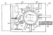
- FIG. 1is a schematic diagram illustrating one exemplary automated system, generally indicated at 100 , for the preparation of a medication.
- the automated system 100is divided into a number of stations where a specific task is performed based on the automated system 100 receiving user input instructions, processing these instructions and then preparing unit doses of one or more medications in accordance with the instructions.
- the automated system 100includes a station 110 where medications and other substances used in the preparation process are stored.
- the term “medication”refers to a medicinal preparation for administration to a patient.
- the medicationis initially stored as a solid, e.g., a powder, to which a diluent is added to form a medicinal composition.
- the station 110functions as a storage unit for storing one or medications, etc. under proper storage conditions.
- medications and the likeare stored in sealed containers, such as vials, that are labeled to clearly indicate the contents of each vial.
- a first station 120is a syringe storage station that houses and stores a number of syringes. For example, up to 500 syringes or more can be disposed in the first station 120 for storage and later use.
- the first station 120can be in the form of a bin or the like or any other type of structure than can hold a number of syringes.
- the syringesare provided as a bandolier structure that permits the syringes to be fed into the other components of the system 100 using standard delivery techniques, such as a conveyor belt, etc.
- the system 100also includes a rotary apparatus 130 for advancing the fed syringes from and to various stations of the system 100 .
- a number of the stationsare arranged circumferentially around the rotary apparatus 130 so that the syringe is first loaded at the first station 120 and then rotated a predetermined distance to a next station, etc. as the medication preparation process advances.
- a different operationis performed with the end result being that a unit dose of medication is disposed within the syringe that is then ready to be administered.
- One exemplary type of rotary apparatus 130is a multiple station cam-indexing dial that is adapted to perform material handling operations.
- the indexeris configured to have multiple stations positioned thereabout with individual nests for each station position.
- One syringeis held within one nest using any number of suitable techniques, including opposing spring-loaded fingers that act to clamp the syringe in its respective nest.
- the indexerpermits the rotary apparatus 130 to be advanced at specific intervals.
- the syringesare loaded into one of the nests of the rotary apparatus 130 .
- One syringeis loaded into one nest of the rotary apparatus 130 in which the syringe is securely held in place.
- the system 100preferably includes additional mechanisms for preparing the syringe for use, such as removing a tip cap at station 150 and extending a plunger of the syringe at a fourth station 160 . At this point, the syringe is ready for use.
- the system 100can include a reading device (not shown) that is capable of reading a label disposed on the sealed container containing the medication.
- the labelis read using any number of suitable reader/scanner devices, such as a bar code reader, etc., so as to confirm that the proper medication has been selected from the storage unit of the station 110 . Multiple readers can be employed in the system at various locations to confirm the accuracy of the entire process.
- the containeris delivered to another station using an automated mechanism, such a robotic gripping device as will be described in greater detail.
- the vialis prepared by removing the safety cap from the sealed container and then cleaning the exposed end of the vial.
- the safety capis removed on a deck of the automated system 100 having a controlled environment. In this manner, the safety cap is removed just-in-time for use.
- the system 100also preferably includes a fifth station (fluid transfer station) 170 for injecting or delivering a diluent into the medication contained in the sealed container and then subsequently mixing the medication and the diluent to form the medication composition that is to be disposed into the prepared syringe.
- a fifth stationfluid transfer station 170 for injecting or delivering a diluent into the medication contained in the sealed container and then subsequently mixing the medication and the diluent to form the medication composition that is to be disposed into the prepared syringe.
- the prepared medication compositionis withdrawn from the container (i.e., vial) and is then delivered into the syringe.
- a cannulacan be inserted into the sealed vial and the medication composition then aspirated into a cannula set.
- the cannulais then withdrawn from the vial and is then rotated relative to the rotary apparatus 130 so that it is in line with (above, below, etc.) the syringe.
- the unit dose of the medication compositionis then delivered to the syringe, as well as additional diluent if necessary or desired.
- the tip capis then placed back on the syringe at a sixth station 180 .
- a seventh station 190prints and station 195 applies a label to the syringe and a device, such as a reader, can be used to verify that this label is placed in a correct location and the printing thereon is readable. Also, the reader can confirm that the label properly identifies the medication composition that is contained in the syringe.
- the syringeis then unloaded from the rotary apparatus 130 at an unloading station 200 and delivered to a predetermined location, such as a new order bin, a conveyor, a sorting device, or a reject bin.
- a predetermined locationsuch as a new order bin, a conveyor, a sorting device, or a reject bin.
- the delivery of the syringecan be accomplished using a standard conveyor or other type of apparatus. If the syringe is provided as a part of the previously-mentioned syringe bandolier, the bandolier is cut prior at a station 198 located prior to the unloading station 200 .
- the various devices that form a part of the system 100 as well as a detailed explanation of the operations that are performed at each stationare described in greater detail in U.S.
- FIGS. 2 and 3shows one type of drug vial 300 that in its simple terms is a drug container that has a vial body 302 for storing a drug and a cap member or some other type of closure element 310 that is sealingly mated to an open end of the drug container 300 opposite a closed end.
- the cap member 310can be releasably attached to the open end or it can be permanently attached after the contents are disposed within the vial body 302 .
- the vial body 302is preferably made of a transparent material so that the contents therein are visible, with one preferred material being glass.
- FIGS. 1 through 6illustrate parts of the fluid transfer station 170 for preparing the syringe for later use and as shown in FIGS. 2 and 3 , one exemplary cannula unit 500 can include a vertical housing 502 that is rotatably coupled to a base 504 between the ends thereof. At an upper end 506 of the housing 502 , a cannula housing 510 is operatively coupled thereto such that the cannula housing 510 can be independently moved in a controlled up and down manner so to either lower it or raise it relative to the drug vial 300 .
- the cannula housing 510can be pneumatically operated and therefore, can include a plurality of shafts 512 which support the cannula housing 510 and extend into an interior of the vertical housing 502 such that when the device is pneumatically operated, the shafts 512 can be driven either out of or into the housing 502 resulting in the cannula housing 510 either being raised or lowered, respectively.
- the cannula housing 510includes a cannula 520 .
- the cannula 520has a distal end 522 that serves to interact with the drug vial 300 for delivering or withdrawing fluid from the drug vial 300 and an opposite end 524 that is operatively coupled to a fluid source, such as a diluent, via tubing or the like.
- a fluid sourcesuch as a diluent, via tubing or the like.
- the housing 510can contain and hold in place a section of fluid conduit (tubing) with a luer fitting or some other type of fitting at the end.
- a robotic device 530then advances forward to a fluid transfer station 530 .
- the fluid transfer station 530is an automated station where the medication (drug) can be processed so that it is in a proper form for injection into one of the syringes 10 that is coupled to the rotary dial 130 .
- a diluente.g., water or other fluid
- the fluid transfer stationis a station where a precise amount of medication is simply aspirated or withdrawn from the vial 300 and delivered to the syringe 10 .
- the cannula unit 500includes a fluid delivery system 600 which includes a main conduit 620 that is operative coupled to the cannula 520 for delivering fluid thereto in a controlled manner, with an opposite end of the main conduit 620 being connected to a fluid pump system 630 that provides the means for creating a negative pressure in the main conduit 620 to cause a precise amount of fluid to be withdrawn into the cannula 520 and the main conduit 620 as well as creating a positive pressure in the main conduit 620 to discharge the fluid (either diluent or medication) that is stored in the main conduit 620 proximate the cannula 520 .
- a fluid delivery system 600which includes a main conduit 620 that is operative coupled to the cannula 520 for delivering fluid thereto in a controlled manner, with an opposite end of the main conduit 620 being connected to a fluid pump system 630 that provides the means for creating a negative pressure in the main conduit 620 to cause a precise amount of fluid to be withdrawn into the cannul
- the fluid pump system 630includes a first syringe 632 and a second syringe 634 , each of which has a plunger or the like 638 which serves to draw fluid into the syringe or expel fluid therefrom.
- the main difference between the first and second syringes 632 , 634is that the amount of fluid that each can hold.
- the first syringe 632has a larger diameter barrel and therefore has increased holding capacity relative to the second syringe 634 .
- the first syringe 632is intended to receive and discharge larger volumes of fluid, while the second syringe 634 performs more of a fine tuning operation in that it precisely can receive and discharge small volumes of fluid.
- the syringes 632 , 634are typically mounted so that an open end 636 thereof is the uppermost portion of the syringe and the plunger 638 is disposed so that it is the lowermost portion of the syringe.
- Each of the syringes 632 , 634is operatively connected to a syringe driver, generally indicated at 640 , which serves to precisely control the movement of the plunger 638 and thus precisely controls the amount (volume) of fluid that is either received or discharged therefrom.
- the driver 640is mechanically linked to the plunger 638 so that controlled actuation thereof causes precise movements of the plunger 638 relative to the barrel of the syringe.
- the driver 640is a stepper motor that can precisely control the distance that the plunger 638 is extended or retracted, which in turn corresponds to a precise volume of fluid being aspirated or discharged.
- each syringe 632 , 634has its own driver 640 so that the corresponding plunger 638 thereof can be precisely controlled and this permits the larger syringe 632 to handle large volumes of fluid, while the smaller syringe 634 handles smaller volumes of fluid.
- stepper motorscan be controlled with a great degree of precision so that the stepper motor can only be driven a small number of steps which corresponds to the plunger 638 being moved a very small distance.
- the stepper motorcan be driven a large number of steps which results in the plunger 638 being moved a much greater distance.
- the drivers 640are preferably a part of a larger automated system that is in communication with a master controller that serves to monitor and control the operation of the various components. For example, the master controller calculates the amount of fluid that is to be either discharged from or aspirated into the cannula 520 and the main conduit 620 and then determines the volume ratio as to how much fluid is to be associated with the first syringe 632 and how much fluid is to be associated with the second syringe 634 . Based on these calculations and determinations, the controller instructs the drivers 640 to operate in a prescribed manner to ensure that the precise amount of volume of fluid is either discharged or aspirated into the main conduit 620 through the cannula 520 .
- each syringe 632 , 634includes one or more connectors to fluidly couple the syringe 632 , 634 with a source 650 of diluent and with the main conduit 620 .
- the first syringe 632includes a first T connector 660 that is coupled to the open end 636 and the second syringe 634 includes a second T connector 662 that is coupled to the open end 636 thereof.
- Each of the legs of the T connectors 660 , 662has an internal valve mechanism or the like 670 that is associated therewith so that each leg as well as the main body that leads to the syringe itself can either be open or closed and this action and setting is independent from the action at the other two conduit members of the connector.
- the valve 670is an internal valve assembly contained within the T connector body itself such that there is a separate valve element for each leg as well as a separate valve element for the main body. It will be appreciated that each of the legs and the main body defines a conduit section and therefore, it is desirable to be able to selectively permit or prevent flow of fluid in a particular conduit section.
- a first leg 661 of the first T connector 660is connected to a first conduit 656 that is connected at its other end to the diluent source 650 and the second leg 663 of the first T connector 660 is connected to a connector conduit (tubing) 652 that is connected at its other end to the first leg of the second T connector 662 associated with the second syringe 634 .
- a main body 665 of the first T connector 660is mated with the open end 636 of the first syringe 632 and defines a flow path thereto.
- the connector conduit 652thus serves to fluidly connect the first and second syringes 632 , 634 .
- the valve mechanism 670is preferably of the type that includes three independently operable valve elements with one associated with one leg 661 , one associated with the other leg 663 and one associated with the main body 665 .
- a first leg 667is connected to the connector conduit 652 and a second leg 669 is connected to a second conduit 658 that is connected to the main conduit 620 or can actually be simply one end of the main conduit.
- a main body 671 of the second T connector 662is mated with the open end 636 of the second syringe 634 .
- the second T connector 662includes an internal valve mechanism 670 that is preferably of the type that includes three independently operable valve elements with one associated with one leg 667 , one associated with the other leg 669 and one associated with the main body 671 .
- valve 670 associated with the second leg 669is first closed so that the communication between the syringes and the main conduit 620 is restricted.
- the valve element 670 associated with first leg 661 of the T connector 660is left open so that a prescribed amount of diluent can be received from the source 650 .
- the valve element associated with the second leg 663 of the T connector 660is initially closed so that the diluent from the diluent source 650 is initially drawn into the first syringe 630 and the valve element associated with the main body 665 is left open so that the diluent can flow into the first syringe 632 .
- the driver 640 associated with the first syringe 632is then actuated for a prescribed period of time resulting in the plunger 638 thereof being extended a prescribed distance.
- the distance that the driver 640 moves the corresponding plunger 638is directly tied to the amount of fluid that is to be received within the syringe 632 .
- the extension of the plunger 638creates negative pressure in the first syringe 632 , thereby causing diluent to be drawn therein.
- valve element associated with the main body 665 of the T connector 660is closed and the valve element associated with the second leg 663 is open, thereby permitting flow from the first T connector 660 to the second T connector 662 .
- valve element associated with the first leg 667 and the main body 671 of the second T connector 662are opened (with the valve element associated with the second leg 669 being kept closed).
- the driver 640 associated with the second syringe 634is then actuated for a prescribed period of time resulting in the plunger 638 thereof being extended a prescribed distance which results in a precise, prescribed amount of fluid being drawn into the second syringe 634 .
- the extension of the plunger 638creates negative pressure within the barrel of the second syringe 634 and since the second T connector 662 is in fluid communication with the diluent source 650 through the first T connector 660 and the connector conduit 652 , diluent can be drawn directly into the second syringe 632 .
- the diluentis not drawn into the first syringe 660 since the valve element associated with the main body 665 of the first T connector 660 is closed.
- the first and second syringes 632 , 634hold in total at least a prescribed volume of diluent that corresponds to at least the precise volume that is to be discharged through the cannula 520 into the vial 300 to reconstitute the medication contained therein.
- the processis essentially reversed with the valve 670 associated with the first leg 661 of the T connector 660 is closed to prevent flow through the first conduit 656 from the diluent source 650 .
- the valve element associated with the second leg 669 of the second T connector 662is opened to permit fluid flow therethrough and into the second conduit 658 to the cannula 520 .
- the diluent that is stored in the first and second syringes 632 , 634can be delivered to the second conduit 658 in a prescribed volume according to any number of different methods, including discharging the diluent from one of the syringes 632 , 634 or discharging the diluent from both of the syringes 634 .
- discharging the diluent from one of the syringes 632 , 634or discharging the diluent from both of the syringes 634 .
- the diluentis drawn from both of the syringes 632 , 634 .
- the diluent contained in the first syringe 632can be introduced into the main conduit 620 by opening the valve associated with the second leg 663 and the main body 665 of the first T connector 660 as well as opening up the valve element associated with the first leg 667 of the second T connector 662 , while the valve element associated with the main body 671 of the second T connector 662 remains closed.
- the valve element associated with the second leg 669remains open.
- the driver 640 associated with the first syringe 632is operated to retract the plunger 638 causing a positive pressure to be exerted and resulting in a volume of the stored diluent being discharged from the first syringe 632 into the connector conduit 652 and ultimately to the second conduit 658 which is in direct fluid communication with the cannula 520 .
- the entire volume of diluent that is needed for the reconstitutioncan be taken from the first syringe 632 or else a portion of the diluent is taken therefrom with an additional amount (fine tuning) to be taken from the second syringe 634 .
- the valve associated with the first leg 667 of the second T connector 662is closed (thereby preventing fluid communication between the syringes 632 , 634 ) and the valve associated with the main body 671 of the second T connector 662 is opened.
- the driver 640 associated with the second syringe 634is then instructed to retract the plunger 638 causing a positive pressure to be exerted and resulting in the stored diluent being discharged from the second syringe 634 into the second conduit 658 .
- any new volume of diluent that is added to the second conduit 658 by one or both of the first and second syringes 632 , 634is discharged at the other end of the main conduit 620 .
- the net resultis that the prescribed amount of diluent that is needed to properly reconstitute the medication is delivered through the cannula 520 and into the vial 300 .
- the cannula 520pierces the septum of the vial and then delivers the diluent to the vial and then the cannula unit 590 and the vial gripper device 530 are inverted to cause agitation and mixing of the contents of the vial.
- first and second syringes 632 , 634may be needed to operate to first receive diluent from the diluent source 650 and then discharge the diluent into the main conduit 520 .
- the fluid pump system 630is then operated so that a prescribed amount of medication is aspirated or otherwise drawn from the vial 300 through the cannula 520 and into the main conduit 620 .
- an air bubbleis introduced into the main conduit 620 to serve as a buffer between the diluent contained in the conduit 620 to be discharged into one vial and the aspirated medication that is to be delivered and discharged into one syringe 10 . It will be appreciated that the two fluids (diluent and prepared medication) can not be allowed to mix together in the conduit 620 .
- the air bubbleserves as an air cap in the tubing of the cannula and serves as an air block used between the fluid in the line (diluent) and the pulled medication.
- the air blockis a 1/10 ml air block; however, this volume is merely exemplary and the size of the air block can be varied.
- the aspiration operationis essentially the opposite of the above operation where the diluent is discharged into the vial 300 . More specifically, the valve 670 associated with the first leg 661 of the first T connector 660 is closed and the valve associated with the second leg 669 of the second T connector 662 is opened to permit flow of the diluent in the main conduit into one or both of the syringes 632 , 634 . As previously mentioned, the second syringe 634 acts more as a means to fine tune the volume of the fluid that is either to be discharged or aspirated.
- the drivers 640 associated with one or both of the first and second syringes 632 , 634are actuated for a prescribed period of time resulting in the plungers 638 thereof being extended a prescribed distance (which can be different from one another).
- the distance that the drivers 640 move the corresponding plungers 638is directly tied to the volume of fluid that is to be received within the corresponding syringe 632 , 634 .
- the aspiration processcan be conducted so that fluid is aspirated into one of the syringes 632 , 634 first and then later an additional amount of fluid can be aspirated into the other syringe 632 , 634 by simply controlling whether the valves in the main bodies 665 , 671 are open or closed.
- valve elements associated with the first and second legs 667 , 669 of the second T connector 662 and the valve element associated with the second leg 663 and main body 665 of the first T connector 660are all open, while the valve elements associated with the first leg 661 of the T connector 660 and the main body 671 of the T connector 662 remain closed.
- valve element associated with the first leg 667simply needs to be closed and then the driver 640 of the second syringe 634 is actuated to extend the plunger 638 .
- the fluid transfer device 580is rotated as is described below to position the cannula 520 relative to one syringe 10 that is nested within the rotary dial 130 . Since the plungers 638 are pulled a prescribed distance that directly translates into a predetermined amount of medication being drawn into the main conduit 620 , the plungers 638 are simply retracted (moved in the opposite direction) the same distance which results in a positive pressure being exerted on the fluid within the main conduit 620 and this causes the pulled medication to be discharged through the cannula 520 and into the syringe 10 .
- valvesare maintained at set positions so that the fluid can be discharged from the first and second syringes 632 , 634 .
- the air blockcontinuously moves within the main conduit 620 toward the cannula 520 .
- the air blockWhen all of the pulled (aspirated) medication is discharged, the air block is positioned at the end of the main conduit signifying that the complete pulled medication dose has been discharged; however, none of the diluent that is stored within the main conduit 620 is discharged into the syringe 10 since the fluid transfer device 580 , and more particularly, the drivers 640 thereof, operates with such precision that only the prescribed medication that has been previously pulled into the main conduit 620 is discharged into the vial 300 .
- the valve elementscan be arranged so that the plungers can be retracted one at a time with only one valve element associated with the main bodies 665 , 671 being open or the plungers can be operated at the same time.
- the fluid transfer device 580may need to make several aspirations and discharges of the medication into the vial 300 in order to inject the complete prescribed medication dosage into the vial 300 .
- the cannula unit 590can operate to first aspirate a prescribed amount of fluid into the main conduit 620 and then is operated so that it rotates over to and above one syringe 10 on the rotary dial 130 , where one incremental dose amount is discharged into the vial 300 .
- the vertical base section 582is rotated so that the cannula unit 590 is brought back the fluid transfer position where the fluid transfer device 582 is operated so that a second incremental dose amount is aspirated into the main conduit 620 in the manner described in detail hereinbefore.
- the vertical base section 582is then rotated again so that the cannula unit 590 is brought back to the rotary dial 130 above the syringe 10 that contains the first incremental dose amount of medication.
- the cannula 520is then lowered so that the cannula tip is placed within the interior of the syringe 10 and the cannula unit 590 (drivers 640 ) is operated so that the second incremental dose amount is discharged into the syringe 10 .
- the processis repeated until the complete medication dose is transferred into the syringe 10 .
- the vial 300 that is positioned at the fluid transfer positioncan either be (1) discarded or (2) it can be delivered to a holding station where it is cataloged and held for additional future use. More specifically, the holding station serves as a parking location where a vial that is not completely used can be used later in the preparation of a downstream syringe 10 .
- the vials 60 that are stored at the holding stationare labeled as multi-use medications that can be reused. These multi-use vials 60 are fully reconstituted so that at the time of the next use, the medication is only aspirated from the vials 60 as opposed to having to first inject diluent to reconstitute the medication.
- a safety featureis provided for monitoring and observing the quality of the medication that is aspirated or otherwise removed from the drug vial 300 into the cannula 520 and the main conduit 620 .
- the safety featureis in the form of a vision system 700 that generally takes and processes an image of the entire surface (landscape) of a drug label 740 ( FIG. 7 ) that is applied around an outer surface (e.g., a circumference) of the drug vial 300 .
- the pictureis processed such that medication (drug) identifying indicia that is present on the label 740 is captured and processed such that the drug that is contained within the drug vial 300 is identified as well as the dosage amount and preferably the expiration date and the lot number of the drug.
- medicationdrug
- the challenges of capturing an image of the drug vial label 740is that the label 740 is affixed to a circular drug vial and therefore, the label 740 is not affixed to a planar surface; however, the present system is configured to overcome this challenge.
- the vision system 700is constructed so that it can take a “rollout” which is an image or can even be a photograph of the decoration, in this case the label 740 , on the circumference of a round object, in this case the drug vial 300 .
- the object (drug vial 300 )is rotated by a special turntable 710 in front of specially adapted camera 720 .
- Camera 720is commercially available from a number of suppliers and can be easily integrated into the present system 100 .
- camera 720 and software and associated hardwareis commercially available from Better Light Company, e.g., a version of Dicomed Field Pro DDC is an excellent digital system that provides digital rollout and large format digital panorama pictures.
- the Belgian systemis a turntable rollout system that includes a 70 mm film camera.
- the 70 mm filmcan be easily digitized by using a flatbed scanner, such as a Umax PowerLook 3.
- Each rollouthas a variable length depending upon the object being imaged, e.g., one rollout can be about 2 inches in length (by 70 mm high). It is important in developing a good quality rollout system that a number of parameters are monitored and controlled in order to produce a high quality rollout photograph. Better rollout systems achieve a high order of precision due to the mathematics of the turntable speed, the circumference of the drug vial, and focusing distance all need to be correctly calculated and expressed.
- Fuzziness in rollout images and photographsis most time an inherent result of a lack synchronization and other factors. For example, when the drug vial and the turntable are out of synch, then the resulting image tends to look out of focus.
- the best rollout systemshave incorporated therein formulas that coordinate and properly integrate the turntable speed and the focusing distance.
- the rollout systemcan be mechanical in nature or it can be more of a computer based system.
- the vision system 700optionally and preferably includes processing equipment that takes the rollout image and applies a coordinate system thereto.
- the rollout image that is taken by the camera 720is stored as a file and the computer overlays a coordinate map over the rollout image so as to be able to identify and look for certain indicia that lie within different defined coordinates or regions of the label.
- the vision system 700can be constructed to perform certain profiling operations, such as profiling where certain indicia (e.g., expiration date) are found on the label 740 and then mapping and storing these locations in a database.
- the label 740is preferably constructed such that the expiration date information lies in one section of the label 740 , while other drug identifying indicia, including a bar code, lie in other locations of the label.
- the process for reading the label with the computeris simplified and can be integrated into the overall system.
- most drug labelsare printed such that the location of the indicia is disposed in a fairly uniform manner and more particularly, the name of the drug and the dosage amount or strength are each generally printed in one or more select regions of the drug label 740 .
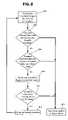
- the computer systemis constructed to first scan these areas and read the drug identifying indicia that may be present within the selected areas as shown in step 802 of FIG. 8 .
- the vision system 700will include some type of optical character recognition software (OCR) 730 .
- OCRoptical character recognition
- ASCIIASCII
- OCRtypically involves the use of a scanner for scanning the object typically in the form of printed matter, etc.
- the rollout cameracan serve generally as a scanner in that the rollout camera and the associated hardware and software can produce not only a physical rollout photograph but more typically, the computer reads and stores a rollout image (e.g., digital image) created by the rollout camera and then processes this image using OCR software and protocol, as well as overlaying a coordinate map, etc.
- a rollout imagee.g., digital image
- label 740is divided into different areas of zone that each present different information or drug identifying indicia.
- one area 742is typically reserved for providing directions of use and any warnings, such as side effects, whereas another area 744 of the label is where dosage strength and frequency is set forth.
- a bar code 746is provided in another coordinate of the label 740 and as previously discussed, the bar code 746 contains certain information, such as the name of the medication and the dosage amount, that helps identify the particular drug vial 300 and its intended use.
- an expiration date 748 and lot information 750are most often included in the form of characters on the label as opposed to being present in a bar code or the like.
- the vision system 700including the database thereof, and the optical character recognition system can be configured so that upon detecting the type of medication and the dosage information, as by reading the NDC bar code, the system then searches a database that is associated with and complementary to the OCR software as shown in step 804 of FIG. 8 . Once the drug is found in the database, the system proceeds to step 806 and if it is not found in the database, then the system is instructed to step 814 .
- This databasecan contain label specific information that concerns the layout of the label in terms of where information is found in the various coordinates.
- the computercan access the database to learn the general make-up of the label that is provided for this drug by this particular manufacturer.
- the databasecan include information that relates to where on such a label the expiration date 748 and lot information 750 are found.
- the OCR system 730 and softwarecan then be instructed to read select coordinate locations for the desired information, e.g., expiration date 748 and lot information 750 .
- mapping of the labelis performed relative to a label 740 that is laid flat to permit an X, Y coordinate system to be laid thereover, this is why it is necessary to first capture and produce a rollout image of the label that is disposed circumferentially around the drug vial 300 .
- the software associated with the vision systemin one aspect, emulates a bar code scanner.
- the OCR software/hardware componentAfter being directed to read select coordinate locations (such as those areas where the expiration date and lot information should be present) to capture any characters that are found in these locations, the OCR software/hardware component recognizes characters from a registered image.
- Document analysisis the process where text is extracted from the document image; however, in our case, the document image is actually the rollout image of the drug label which is stored as a file in the computer.
- the character recognition stepconsists of two main components, namely, the feature extractor and the classifier.
- the feature extractoror Intelligent Character Recognition
- the obtained featuresare used as input to the character classifier.
- the classification methodis done by comparing an input character image with a set of templates from each character class. This operation is also known as a template matching method. After all templates have been compared, the character's identity is allocated as the identity of the most familiar template.
- Yet another classification methodis called the structural classification method that uses structural features and decision rules in categorizing characters.
- Structural featurescan be described in terms of character strokes, holes or other attributes.
- the character “B”can be described as a vertical stroke with two holes attached to it on the upper and lower right side.
- Contextual processingis a post-process operation where information is recognized. For instance, recognizing a street name in an address by correctly recognizing the zip code.
- the post-processfollows the application of a spell checker feature to ensure the correct spelling of words.
- the OCR systemis instructed and directed to read a coordinate section of the rollout image of the label where the expiration date and lot information should be, the characters in this area are recognized and then through the contextual processing step, the expiration date and the lot information is determined as shown in step 806 of FIG. 8 .
- the expiration dateis obviously presented in the form of a date and therefore will include some numbers regardless of the formatting of the date.
- the expiration datecould be presented in an abbreviated form, such as mm/dd/yy or mm/dd/yyyy or it can be present in more of a long form, such as Month dd, yyyy.
- the expiration datecan be expressed in the format “mm/yy” which is interpreted to be the last day of the month “mm” in the year “yy”. For example an expiration date of 09/04 in this format is interpreted to mean 09/30/2004.
- one or more numbersshould be a part of the detected expiration date 748 and therefore, if the OCR system does not recognize and detect any numbers as being part of the expiration date, a red flag, so to speak, should be raised.
- the databasecan be consulted again to double check the coordinate locations for the expiration date 748 and the lot number 750 and then the process can be repeated to see if any characters are present in the selected coordinate locations that should correspond to the expiration date and lot information coordinate locations.
- the detected expiration date 748is compared to the present date (a threshold value) to ascertain whether the present date is already beyond the expiration date 748 or to determine how many days until the expiration date 748 as shown in step 806 .
- a threshold valueFor example if the expiration date will occur in a relatively short period of time, such as a few weeks, a decision can be made as to whether the drug vial 300 should be further processed or whether it should just be discarded.
- step 806the system proceeds to step 808 .
- this informationis used to determine whether this particular drug has been subject to a recall order or some other type of order as shown in step 808 of FIG. 8 .
- the recall ordertypically identifies the medication that is to be discarded and not used by its lot information.
- a number of different type of productsare distributed by packaging a number of smaller products into a large package, such as a crate or pallet.
- the medicationis prepared in batches that are identified by lot information in order to keep track of which individual products originated from one particular batch.
- lot informationIn order to keep track of which individual products originated from one particular batch.
- the manufacturer and any authorities involvedwill first determine the origin of the medication. In other words, the lot information of the contaminated product is identified and at the very least, all drug products that originated from the same identified lot are listed in the recall since there is a risk that the entire batch is contaminated.
- the detected lot number 750is then compared to lot numbers that are listed in the constantly updated database that contains lot numbers for products that have been recalled as shown in step 810 . If the detected lot number 750 matches a lot number that is contained on the recall list, then a signal is generated to alert the user as to this fact and permit the user to take the necessary steps as shown in step 814 . For example, if it is found that the product is part of the recall order, then the product should be isolated and not administered but rather should be packaged and sent back to the manufacturer or to the entity identified on the recall order. Also, this event should prompt the user to check other identical or similar medications to see if they are likewise part of the same recall order. If other medications are found that are part of the recall order, then all of the medications can be quarantined from the other medications and specially marked for return.
- step 812the system is instructed to step 812 and the drug vial can be further processed as by withdrawing a predetermined amount of medication or by reconstituting the medication in the drug vial.
- the expiration date and lot informationis not set forth on the label as characters in a specific section of the label but rather, this information can be incorporated as part of an expanded bar code or a second bar code that is separate from the NDC bar code.
- the expiration datecan be represented as a set of numbers in bar code formatting at a specific location or segment thereof
- the lot informationcan be represented as a set of numbers in bar code formatting at a second location or segment of the bar code.
- the second bar codecan be in the form of a linear bar code. The second bar code can be placed in a select section of the label and the associated coordinates of this section are entered into the database so that the OCR system can be instructed to look in this select location for the second bar code.
- the vision system softwareemulates a bar code reader or scanner and is configured to read such a bar code and process the information accordingly from reading the rollout image.
- the bar codecan be broken into individual segments such that each individual segment of the bar code represents a different piece of information, such as the name of the medication, the dosage, etc.
- the vision system 700 and more particularly the character recognition softwareis configured to emulate a bar code reader or scanner so as to permit the vision system 700 to detect indicia on the label 740 that would otherwise not be detected by a standard bar code reader or some other type of reader.
- the optical character recognition software of the vision system 700is preferably provided in order to read the expiration date 748 and lot information 750 , etc., while the bar code software reads the bar code (e.g., NDC bar code) to ascertain the drug name, dosage information, etc.
- the bar codee.g., NDC bar code
- the bar code softwarewill not detect any bar code as part of the rollout image and is merely inactive; however, the label still will have expiration date 748 and lot information 750 that can be checked by the vision system in the manner described above.
- the operatorcan be signaled that a manual inspection is recommended or suggested, or some other type of sensing mechanism can be used to ascertain whether the drug vial 300 contains the proper medication at the proper dose.
- optical readers and the OCR techniques described above for reading the expiration date 748 and lot information 750could be used to scan and read the region of the vial 300 that contains the drug identifying indicia.
- the present automated systemovercomes a number of the deficiencies that were associated with the prior art systems and more particularly, the present system provides a system that can capture and process drug identifying indicia that is present on the label. Since the label is disposed on an outer surface of the drug vial that has an annular shape, the label extends about a circumference of the drug vial and this prevents an imaging device from having a clear view of the entire label and therefore, the device will fail to capture all of the drug identifying indicia contained thereon. By incorporating rollout imaging techniques, the present system overcomes this problem since the special mechanics of the roll out camera and the rotation of the drug vial permit the entire surface of the label to be captured by the camera.
- the vision systemcan profile and map and store in a database where certain drug identifying indicia should be found and then this information is later used to drive the components of the vision system in an effort to detect the drug identifying indicia and process the information so that a decision as to whether the drug vial should be advanced to the next station can be made.
Landscapes
- Physics & Mathematics (AREA)
- General Physics & Mathematics (AREA)
- Engineering & Computer Science (AREA)
- Theoretical Computer Science (AREA)
- Medical Preparation Storing Or Oral Administration Devices (AREA)
Abstract
Description
Claims (49)
Priority Applications (1)
| Application Number | Priority Date | Filing Date | Title |
|---|---|---|---|
| US10/873,420US7017623B2 (en) | 2004-06-21 | 2004-06-21 | Automated use of a vision system to unroll a label to capture and process drug identifying indicia present on the label |
Applications Claiming Priority (1)
| Application Number | Priority Date | Filing Date | Title |
|---|---|---|---|
| US10/873,420US7017623B2 (en) | 2004-06-21 | 2004-06-21 | Automated use of a vision system to unroll a label to capture and process drug identifying indicia present on the label |
Publications (2)
| Publication Number | Publication Date |
|---|---|
| US20050279419A1 US20050279419A1 (en) | 2005-12-22 |
| US7017623B2true US7017623B2 (en) | 2006-03-28 |
Family
ID=35479344
Family Applications (1)
| Application Number | Title | Priority Date | Filing Date |
|---|---|---|---|
| US10/873,420Expired - LifetimeUS7017623B2 (en) | 2004-06-21 | 2004-06-21 | Automated use of a vision system to unroll a label to capture and process drug identifying indicia present on the label |
Country Status (1)
| Country | Link |
|---|---|
| US (1) | US7017623B2 (en) |
Cited By (73)
| Publication number | Priority date | Publication date | Assignee | Title |
|---|---|---|---|---|
| US20050278066A1 (en)* | 2004-06-15 | 2005-12-15 | Kevin Graves | Automated dispensing system and associated method of use |
| US7325667B1 (en)* | 2003-10-10 | 2008-02-05 | Damick Keith D | Systems and methods for feeding articles to and removing articles from an automatic washer |
| US20080169046A1 (en)* | 2006-10-20 | 2008-07-17 | Forhealth Technologies, Inc. | Automated drug preparation apparatus including a bluetooth communications network |
| US20080171981A1 (en)* | 2007-01-11 | 2008-07-17 | Forhealth Technologies, Inc. | Tamper evident cap for a drug delivery device |
| US20090038709A1 (en)* | 2005-04-13 | 2009-02-12 | Medical Dispensing Systems B.V. | Device for automatically filling product containers with a liquid comprising one or more medicines |
| US20090126825A1 (en)* | 2007-11-16 | 2009-05-21 | Intelligent Hospital Systems Ltd. | Method and Apparatus for Automated Fluid Transfer Operations |
| US20100100234A1 (en)* | 2006-10-20 | 2010-04-22 | Forhealth Technologies, Inc. | Automated drug preparation apparatus including syringe loading, preparation and filling |
| WO2010027717A3 (en)* | 2008-08-23 | 2010-05-14 | United States Pharmaceutical Distributors, Inc. | Automated pharmacy drug handling and prescription verification system and method |
| WO2010022345A3 (en)* | 2008-08-22 | 2010-05-14 | Robert Terzini | Container dispersion and filling system |
| US7900658B2 (en) | 2006-10-20 | 2011-03-08 | Fht, Inc. | Automated drug preparation apparatus including drug vial handling, venting, cannula positioning functionality |
| US20110062703A1 (en)* | 2009-07-29 | 2011-03-17 | Icu Medical, Inc. | Fluid transfer devices and methods of use |
| US20110100501A1 (en)* | 2009-03-31 | 2011-05-05 | Osamu Mizuno | Medication mixing device and medication mixing method |
| US20110135144A1 (en)* | 2009-07-01 | 2011-06-09 | Hand Held Products, Inc. | Method and system for collecting voice and image data on a remote device and coverting the combined data |
| US20110146835A1 (en)* | 2008-08-23 | 2011-06-23 | Robert Terzini | Automated pharmacy drug handling and prescription verification system and method |
| US20110153066A1 (en)* | 2008-08-22 | 2011-06-23 | Robert Terzini | Container dispersion wheel |
| US20120130308A1 (en)* | 2005-04-11 | 2012-05-24 | Hospira, Inc. | User interface improvements for medical devices |
| US8328082B1 (en)* | 2010-05-30 | 2012-12-11 | Crisi Medical Systems, Inc. | Medication container encoding, verification, and identification |
| US20120330152A1 (en)* | 2009-11-27 | 2012-12-27 | Claus-Peter Reisinger | Fluid management system |
| US8353869B2 (en) | 2010-11-02 | 2013-01-15 | Baxa Corporation | Anti-tampering apparatus and method for drug delivery devices |
| US20130306190A1 (en)* | 2011-04-06 | 2013-11-21 | Mitsubishi Heavy Industries Food & Packaging Machine Co., Ltd. | Rotary-type filling machine and method for calculating filling quantity for rotary-type filling machine |
| US8702674B2 (en) | 2010-04-27 | 2014-04-22 | Crisi Medical Systems, Inc. | Medication and identification information transfer apparatus |
| US9039655B2 (en) | 2009-11-06 | 2015-05-26 | Crisi Medical Systems, Inc. | Medication injection site and data collection system |
| US9078809B2 (en) | 2011-06-16 | 2015-07-14 | Crisi Medical Systems, Inc. | Medication dose preparation and transfer system |
| US9150119B2 (en) | 2013-03-15 | 2015-10-06 | Aesynt Incorporated | Apparatuses, systems, and methods for anticipating and delivering medications from a central pharmacy to a patient using a track based transport system |
| US20160045876A1 (en)* | 2013-03-15 | 2016-02-18 | Baxter Corporation Englewood | Systems and methods for compounding a preparation using a premix solution |
| US9511945B2 (en) | 2012-10-12 | 2016-12-06 | Aesynt Incorporated | Apparatuses, systems, and methods for transporting medications from a central pharmacy to a patient in a healthcare facility |
| US9744298B2 (en) | 2011-06-22 | 2017-08-29 | Crisi Medical Systems, Inc. | Selectively controlling fluid flow through a fluid pathway |
| US9849236B2 (en) | 2013-11-25 | 2017-12-26 | Icu Medical, Inc. | Methods and systems for filling IV bags with therapeutic fluid |
| US9883987B2 (en) | 2011-12-22 | 2018-02-06 | Icu Medical, Inc. | Fluid transfer devices and methods of use |
| US9930297B2 (en) | 2010-04-30 | 2018-03-27 | Becton, Dickinson And Company | System and method for acquiring images of medication preparations |
| US9931498B2 (en) | 2013-03-13 | 2018-04-03 | Crisi Medical Systems, Inc. | Injection site information cap |
| US10022498B2 (en) | 2011-12-16 | 2018-07-17 | Icu Medical, Inc. | System for monitoring and delivering medication to a patient and method of using the same to minimize the risks associated with automated therapy |
| US10166328B2 (en) | 2013-05-29 | 2019-01-01 | Icu Medical, Inc. | Infusion system which utilizes one or more sensors and additional information to make an air determination regarding the infusion system |
| USD837983S1 (en) | 2015-12-04 | 2019-01-08 | Icu Medical, Inc. | Fluid transfer device |
| US10293107B2 (en) | 2011-06-22 | 2019-05-21 | Crisi Medical Systems, Inc. | Selectively Controlling fluid flow through a fluid pathway |
| USD851745S1 (en) | 2016-07-19 | 2019-06-18 | Icu Medical, Inc. | Medical fluid transfer system |
| US10347374B2 (en) | 2008-10-13 | 2019-07-09 | Baxter Corporation Englewood | Medication preparation system |
| US10342917B2 (en) | 2014-02-28 | 2019-07-09 | Icu Medical, Inc. | Infusion system and method which utilizes dual wavelength optical air-in-line detection |
| US10417758B1 (en) | 2005-02-11 | 2019-09-17 | Becton, Dickinson And Company | System and method for remotely supervising and verifying pharmacy functions |
| US10430761B2 (en) | 2011-08-19 | 2019-10-01 | Icu Medical, Inc. | Systems and methods for a graphical interface including a graphical representation of medical data |
| US10463788B2 (en) | 2012-07-31 | 2019-11-05 | Icu Medical, Inc. | Patient care system for critical medications |
| US10578474B2 (en) | 2012-03-30 | 2020-03-03 | Icu Medical, Inc. | Air detection system and method for detecting air in a pump of an infusion system |
| US10596316B2 (en) | 2013-05-29 | 2020-03-24 | Icu Medical, Inc. | Infusion system and method of use which prevents over-saturation of an analog-to-digital converter |
| US10635784B2 (en) | 2007-12-18 | 2020-04-28 | Icu Medical, Inc. | User interface improvements for medical devices |
| US10646405B2 (en) | 2012-10-26 | 2020-05-12 | Baxter Corporation Englewood | Work station for medical dose preparation system |
| US10656894B2 (en) | 2017-12-27 | 2020-05-19 | Icu Medical, Inc. | Synchronized display of screen content on networked devices |
| US10679342B2 (en) | 2014-09-08 | 2020-06-09 | Becton, Dickinson And Company | Aerodynamically streamlined enclosure for input devices of a medication preparation system |
| US10818387B2 (en) | 2014-12-05 | 2020-10-27 | Baxter Corporation Englewood | Dose preparation data analytics |
| US10850024B2 (en) | 2015-03-02 | 2020-12-01 | Icu Medical, Inc. | Infusion system, device, and method having advanced infusion features |
| US10874793B2 (en) | 2013-05-24 | 2020-12-29 | Icu Medical, Inc. | Multi-sensor infusion system for detecting air or an occlusion in the infusion system |
| US10971257B2 (en) | 2012-10-26 | 2021-04-06 | Baxter Corporation Englewood | Image acquisition for medical dose preparation system |
| US11013857B2 (en) | 2016-07-06 | 2021-05-25 | Bayer Healthcare Llc | Contrast heating system with in-line contrast warmer |
| US11020541B2 (en) | 2016-07-25 | 2021-06-01 | Icu Medical, Inc. | Systems, methods, and components for trapping air bubbles in medical fluid transfer modules and systems |
| US11107574B2 (en) | 2014-09-30 | 2021-08-31 | Baxter Corporation Englewood | Management of medication preparation with formulary management |
| US11135360B1 (en) | 2020-12-07 | 2021-10-05 | Icu Medical, Inc. | Concurrent infusion with common line auto flush |
| US11246985B2 (en) | 2016-05-13 | 2022-02-15 | Icu Medical, Inc. | Infusion pump system and method with common line auto flush |
| WO2022046554A1 (en)* | 2020-08-28 | 2022-03-03 | Omnicell, Inc. | Systems and methods for parallel preparation processing |
| US11273103B1 (en) | 2021-06-22 | 2022-03-15 | Vmi Holland B.V. | Method, computer program product and dispensing device for dispensing discrete medicaments |
| US11278671B2 (en) | 2019-12-04 | 2022-03-22 | Icu Medical, Inc. | Infusion pump with safety sequence keypad |
| US11324888B2 (en) | 2016-06-10 | 2022-05-10 | Icu Medical, Inc. | Acoustic flow sensor for continuous medication flow measurements and feedback control of infusion |
| US11344668B2 (en) | 2014-12-19 | 2022-05-31 | Icu Medical, Inc. | Infusion system with concurrent TPN/insulin infusion |
| US11344673B2 (en) | 2014-05-29 | 2022-05-31 | Icu Medical, Inc. | Infusion system and pump with configurable closed loop delivery rate catch-up |
| US11367533B2 (en) | 2014-06-30 | 2022-06-21 | Baxter Corporation Englewood | Managed medical information exchange |
| US11498761B1 (en) | 2021-06-22 | 2022-11-15 | Vmi Holland B.V. | Method for dispensing discrete medicaments, a test station for testing a feeder unit, and a method for determining a fill level of a feeder unit |
| US11575673B2 (en) | 2014-09-30 | 2023-02-07 | Baxter Corporation Englewood | Central user management in a distributed healthcare information management system |
| US11590057B2 (en) | 2020-04-03 | 2023-02-28 | Icu Medical, Inc. | Systems, methods, and components for transferring medical fluids |
| US11673700B2 (en) | 2021-06-22 | 2023-06-13 | Vmi Holland B.V. | Device and methods for packaging medicaments with fault detection |
| US11857497B2 (en) | 2022-03-08 | 2024-01-02 | Equashield Medical Ltd | Fluid transfer station in a robotic pharmaceutical preparation system |
| US11883361B2 (en) | 2020-07-21 | 2024-01-30 | Icu Medical, Inc. | Fluid transfer devices and methods of use |
| US11948112B2 (en) | 2015-03-03 | 2024-04-02 | Baxter Corporation Engelwood | Pharmacy workflow management with integrated alerts |
| US12350233B2 (en) | 2021-12-10 | 2025-07-08 | Icu Medical, Inc. | Medical fluid compounding systems with coordinated flow control |
| USD1091564S1 (en) | 2021-10-13 | 2025-09-02 | Icu Medical, Inc. | Display screen or portion thereof with graphical user interface for a medical device |
| US12412644B2 (en) | 2014-10-24 | 2025-09-09 | Baxter Corporation Englewood | Automated exchange of healthcare information for fulfillment of medication doses |
Families Citing this family (37)
| Publication number | Priority date | Publication date | Assignee | Title |
|---|---|---|---|---|
| US7753085B2 (en) | 2002-12-03 | 2010-07-13 | Forhealth Technologies, Inc. | Automated drug preparation apparatus including automated drug reconstitution |
| US10688021B2 (en) | 2002-12-03 | 2020-06-23 | Baxter Corporation Englewood | Automated drug preparation apparatus including automated drug reconstitution |
| WO2006069361A2 (en)* | 2004-12-22 | 2006-06-29 | Intelligent Hospital Systems Ltd. | Automated pharmacy admixture system (apas) |
| US7783383B2 (en)* | 2004-12-22 | 2010-08-24 | Intelligent Hospital Systems Ltd. | Automated pharmacy admixture system (APAS) |
| EP2457550B8 (en)* | 2005-05-16 | 2016-07-13 | ARxIUM Inc. | Automated pharmacy admixture system (APAS) |
| US7931859B2 (en) | 2005-12-22 | 2011-04-26 | Intelligent Hospital Systems Ltd. | Ultraviolet sanitization in pharmacy environments |
| CA2849553C (en)* | 2006-07-26 | 2015-09-29 | Daniele Baldassari | Machine for the preparation of pharmaceutical products |
| WO2008055194A2 (en)* | 2006-10-31 | 2008-05-08 | Forhealth Technologies, Inc. | Automated drug preparation apparatus including drug reconstitution and serial dilution functionality |
| US7913720B2 (en)* | 2006-10-31 | 2011-03-29 | Fht, Inc. | Automated drug preparation apparatus including serial dilution functionality |
| CA2668981C (en) | 2006-11-09 | 2016-10-04 | Intelligent Hospital Systems Ltd. | Control of fluid transfer operations |
| US8271138B2 (en)* | 2007-09-12 | 2012-09-18 | Intelligent Hospital Systems Ltd. | Gripper device |
| DE602007005945D1 (en)* | 2007-10-08 | 2010-05-27 | Iner Aec Executive Yuan | Automatic dispenser for radiopharmaceuticals |
| US8386070B2 (en) | 2009-03-18 | 2013-02-26 | Intelligent Hospital Systems, Ltd | Automated pharmacy admixture system |
| US8818821B2 (en)* | 2010-01-29 | 2014-08-26 | Medarchiver S.R.L. | Digital assistant appliance for assisting an operator in the manual preparation of a liquid pharmaceutical composition in a medical instrument for administering the composition to a patient, and corresponding operating method |
| US20130194414A1 (en)* | 2010-03-05 | 2013-08-01 | Frédéric Poirier | Verification system for prescription packaging and method |
| US10492991B2 (en) | 2010-05-30 | 2019-12-03 | Crisi Medical Systems, Inc. | Medication container encoding, verification, and identification |
| US9514131B1 (en)* | 2010-05-30 | 2016-12-06 | Crisi Medical Systems, Inc. | Medication container encoding, verification, and identification |
| US20130117044A1 (en)* | 2011-11-05 | 2013-05-09 | James Kalamas | System and method for generating a medication inventory |
| CN103129890B (en)* | 2011-11-24 | 2015-08-12 | 苏州艾隆科技股份有限公司 | Rotary medicine delivery machine |
| WO2014189834A1 (en)* | 2013-05-18 | 2014-11-27 | Codonics, Inc. | Medicinal substance identification based on container recognition |
| FR3007613A1 (en)* | 2013-06-20 | 2014-12-26 | Eurekam | SHOOTING DEVICE FOR SECURE PREPARATION OF MEDICINAL PREPARATIONS, ASSOCIATED OBJECT POSITIONING MEDIUM, AND SYSTEM INCLUDING SUCH A DEVICE AND SUCH A MEDIUM |
| JP5601486B1 (en)* | 2013-12-19 | 2014-10-08 | セイコーエプソン株式会社 | Sales management support system |
| US10837977B2 (en) | 2015-05-11 | 2020-11-17 | Kabushiki Kaisha Yaskawa Denki | Rack for dispensing and dispensing system |
| WO2016181466A1 (en)* | 2015-05-11 | 2016-11-17 | 株式会社安川電機 | Dispensing system, controller, and control method |
| US20170076441A1 (en)* | 2015-09-10 | 2017-03-16 | Teri Lynn Peterson | System and Method for Locating Errors in the Distribution of Prescribed Pills in an Organizer Box of Sequential Compartments Holding the Pills Therein |
| MX385034B (en)* | 2016-01-22 | 2025-03-14 | Baxter Int | METHOD AND MACHINE FOR THE PRODUCTION OF STERILE SOLUTION PRODUCT BAGS. |
| WO2017127625A1 (en) | 2016-01-22 | 2017-07-27 | Baxter International Inc. | Sterile solutions product bag |
| EP3399463A1 (en)* | 2017-05-05 | 2018-11-07 | Ares Trading S.A. | Method and apparatus for determining information about a drug-containing vessel |
| WO2020162310A1 (en)* | 2019-02-05 | 2020-08-13 | 富士フイルム株式会社 | Management system |
| WO2021007154A1 (en)* | 2019-07-05 | 2021-01-14 | Norton (Waterford) Limited | Drug delivery device with electronics and power management |
| EP4126112A4 (en)* | 2020-04-29 | 2024-08-07 | Becton, Dickinson and Company | SMART SYRINGE WITH DOSE CAPTURE AND SMARTPHONE APP |
| CN115187968A (en)* | 2021-03-23 | 2022-10-14 | 深圳市联新移动医疗科技有限公司 | Injection medicine identification method and system based on machine vision and intelligent dispensing equipment |
| CN114030856B (en)* | 2021-11-10 | 2023-12-22 | 佛山市三水飞马包装有限公司 | Automatic handle sleeving device based on visual recognition and intelligent control method |
| CN115201504A (en)* | 2022-07-05 | 2022-10-18 | 中科育成(天津)科技发展有限公司 | Target detection system and method |
| CN115438679A (en)* | 2022-08-18 | 2022-12-06 | 深圳市日联科技有限公司 | Bar code visual identification device on column |
| US12387509B2 (en)* | 2023-01-31 | 2025-08-12 | Saudi Arabian Oil Company | Sample labeling method using image-matching |
| WO2024246908A1 (en)* | 2023-06-01 | 2024-12-05 | Equashield Medical Ltd | Imaging-based pharmaceutical content verification in a robotic preparation system |
Citations (16)
| Publication number | Priority date | Publication date | Assignee | Title |
|---|---|---|---|---|
| US2981432A (en) | 1958-04-17 | 1961-04-25 | Dennison Mfg Co | Indicia-applying apparatus |
| US3835897A (en) | 1971-10-18 | 1974-09-17 | L Gess | Apparatus for filling and labeling containers |
| US3880211A (en) | 1971-10-18 | 1975-04-29 | Larry C Gess | Apparatus for filling containers |
| US4472357A (en) | 1981-11-18 | 1984-09-18 | Medical Laboratory Automation, Inc. | Blood bank cuvette cassette and label therefor |
| US4535820A (en) | 1984-05-24 | 1985-08-20 | Burron Medical Inc. | Normally closed check valve |
| US4683916A (en) | 1986-09-25 | 1987-08-04 | Burron Medical Inc. | Normally closed automatic reflux valve |
| US4823982A (en) | 1985-04-11 | 1989-04-25 | Medical Microsystems, Inc. | Multiple cartridge dispensing system |
| US4921277A (en) | 1988-10-24 | 1990-05-01 | Academy Of Applied Science, Inc. | Method of labeling needle syringes and medication vials and novel labels therefor |
| US5188696A (en) | 1991-07-31 | 1993-02-23 | Good Jr Kenneth W | Wrap around labeling machine |
| US5341854A (en) | 1989-09-28 | 1994-08-30 | Alberta Research Council | Robotic drug dispensing system |
| US5651775A (en) | 1995-07-12 | 1997-07-29 | Walker; Richard Bradley | Medication delivery and monitoring system and methods |
| US5805454A (en) | 1995-08-10 | 1998-09-08 | Valerino, Sr.; Fred M. | Parenteral products automation system (PPAS) |
| US5911252A (en) | 1997-04-29 | 1999-06-15 | Cassel; Douglas | Automated syringe filling system for radiographic contrast agents and other injectable substances |
| US6048086A (en) | 1995-08-10 | 2000-04-11 | Valerino, Sr.; Fred M. | Parenteral products automatic system (PPAS) with an oral/solid interface |
| US20020020459A1 (en) | 2000-08-10 | 2002-02-21 | Baldwin Brian Eugene | Method, system, and apparatus for handling, labeling, filling and capping syringes |
| US20030012913A1 (en) | 2001-07-11 | 2003-01-16 | Peter Seidl | Label for labelling of preferably cylind rical containers |
- 2004
- 2004-06-21USUS10/873,420patent/US7017623B2/ennot_activeExpired - Lifetime
Patent Citations (18)
| Publication number | Priority date | Publication date | Assignee | Title |
|---|---|---|---|---|
| US2981432A (en) | 1958-04-17 | 1961-04-25 | Dennison Mfg Co | Indicia-applying apparatus |
| US3835897A (en) | 1971-10-18 | 1974-09-17 | L Gess | Apparatus for filling and labeling containers |
| US3880211A (en) | 1971-10-18 | 1975-04-29 | Larry C Gess | Apparatus for filling containers |
| US4472357A (en) | 1981-11-18 | 1984-09-18 | Medical Laboratory Automation, Inc. | Blood bank cuvette cassette and label therefor |
| US4535820A (en) | 1984-05-24 | 1985-08-20 | Burron Medical Inc. | Normally closed check valve |
| US4823982A (en) | 1985-04-11 | 1989-04-25 | Medical Microsystems, Inc. | Multiple cartridge dispensing system |
| US4683916A (en) | 1986-09-25 | 1987-08-04 | Burron Medical Inc. | Normally closed automatic reflux valve |
| US4921277A (en) | 1988-10-24 | 1990-05-01 | Academy Of Applied Science, Inc. | Method of labeling needle syringes and medication vials and novel labels therefor |
| US5341854A (en) | 1989-09-28 | 1994-08-30 | Alberta Research Council | Robotic drug dispensing system |
| US5188696A (en) | 1991-07-31 | 1993-02-23 | Good Jr Kenneth W | Wrap around labeling machine |
| US5651775A (en) | 1995-07-12 | 1997-07-29 | Walker; Richard Bradley | Medication delivery and monitoring system and methods |
| US5805454A (en) | 1995-08-10 | 1998-09-08 | Valerino, Sr.; Fred M. | Parenteral products automation system (PPAS) |
| US6048086A (en) | 1995-08-10 | 2000-04-11 | Valerino, Sr.; Fred M. | Parenteral products automatic system (PPAS) with an oral/solid interface |
| US20020198738A1 (en) | 1995-08-10 | 2002-12-26 | Forhealth Technologies, Inc. | Parenteral products automation system (PPAS) |
| US5911252A (en) | 1997-04-29 | 1999-06-15 | Cassel; Douglas | Automated syringe filling system for radiographic contrast agents and other injectable substances |
| US20020020459A1 (en) | 2000-08-10 | 2002-02-21 | Baldwin Brian Eugene | Method, system, and apparatus for handling, labeling, filling and capping syringes |
| US20040088951A1 (en) | 2000-08-10 | 2004-05-13 | Baldwin Brian Eugene | Method, system, and apparatus for handling, labeling, filling, and capping syringes |
| US20030012913A1 (en) | 2001-07-11 | 2003-01-16 | Peter Seidl | Label for labelling of preferably cylind rical containers |
Cited By (182)
| Publication number | Priority date | Publication date | Assignee | Title |
|---|---|---|---|---|
| US7325667B1 (en)* | 2003-10-10 | 2008-02-05 | Damick Keith D | Systems and methods for feeding articles to and removing articles from an automatic washer |
| US20080105515A1 (en)* | 2003-10-10 | 2008-05-08 | Mack Design, Inc. | Systems and methods for feeding articles to and removing articles from an automatic washer |
| US20050278066A1 (en)* | 2004-06-15 | 2005-12-15 | Kevin Graves | Automated dispensing system and associated method of use |
| US7163031B2 (en)* | 2004-06-15 | 2007-01-16 | Mallinckrodt Inc. | Automated dispensing system and associated method of use |
| US10417758B1 (en) | 2005-02-11 | 2019-09-17 | Becton, Dickinson And Company | System and method for remotely supervising and verifying pharmacy functions |
| US20120130308A1 (en)* | 2005-04-11 | 2012-05-24 | Hospira, Inc. | User interface improvements for medical devices |
| US8577692B2 (en)* | 2005-04-11 | 2013-11-05 | Hospira, Inc. | User interface improvements for medical devices |
| US8276623B2 (en)* | 2005-04-13 | 2012-10-02 | Medical Dispensing Systems B.V. | Device for automatically filling product containers with a liquid comprising one or more medicines |
| US20090038709A1 (en)* | 2005-04-13 | 2009-02-12 | Medical Dispensing Systems B.V. | Device for automatically filling product containers with a liquid comprising one or more medicines |
| US20100100234A1 (en)* | 2006-10-20 | 2010-04-22 | Forhealth Technologies, Inc. | Automated drug preparation apparatus including syringe loading, preparation and filling |
| US20100097465A1 (en)* | 2006-10-20 | 2010-04-22 | Forhealth Technologies, Inc. | Automated drug preparation apparatus including syringe loading, preparation and filling |
| US8037659B2 (en) | 2006-10-20 | 2011-10-18 | Forhealth Technologies, Inc. | Automated drug preparation apparatus including syringe loading, preparation and filling |
| US7814731B2 (en) | 2006-10-20 | 2010-10-19 | Forhealth Technologies, Inc. | Automated drug preparation apparatus including a bluetooth communications network |
| US7900658B2 (en) | 2006-10-20 | 2011-03-08 | Fht, Inc. | Automated drug preparation apparatus including drug vial handling, venting, cannula positioning functionality |
| US8209941B2 (en) | 2006-10-20 | 2012-07-03 | Fht, Inc. | Automated drug preparation apparatus including syringe loading, preparation and filling |
| US20080169046A1 (en)* | 2006-10-20 | 2008-07-17 | Forhealth Technologies, Inc. | Automated drug preparation apparatus including a bluetooth communications network |
| US20100145270A1 (en)* | 2007-01-11 | 2010-06-10 | Abdul Wahid Khan | Tamper evident cap for a drug delivery device |
| US20080171981A1 (en)* | 2007-01-11 | 2008-07-17 | Forhealth Technologies, Inc. | Tamper evident cap for a drug delivery device |
| US8225824B2 (en)* | 2007-11-16 | 2012-07-24 | Intelligent Hospital Systems, Ltd. | Method and apparatus for automated fluid transfer operations |
| US20090126825A1 (en)* | 2007-11-16 | 2009-05-21 | Intelligent Hospital Systems Ltd. | Method and Apparatus for Automated Fluid Transfer Operations |
| US10635784B2 (en) | 2007-12-18 | 2020-04-28 | Icu Medical, Inc. | User interface improvements for medical devices |
| WO2010022345A3 (en)* | 2008-08-22 | 2010-05-14 | Robert Terzini | Container dispersion and filling system |
| US20110153066A1 (en)* | 2008-08-22 | 2011-06-23 | Robert Terzini | Container dispersion wheel |
| US20110146212A1 (en)* | 2008-08-22 | 2011-06-23 | Robert Terzini | Container dispersion and filling system |
| US8745961B2 (en) | 2008-08-22 | 2014-06-10 | Tension International, Inc. | Container dispersion and filling system |
| US8511478B2 (en) | 2008-08-22 | 2013-08-20 | Tension International, Inc. | Container dispersion wheel |
| WO2010027717A3 (en)* | 2008-08-23 | 2010-05-14 | United States Pharmaceutical Distributors, Inc. | Automated pharmacy drug handling and prescription verification system and method |
| US20110146835A1 (en)* | 2008-08-23 | 2011-06-23 | Robert Terzini | Automated pharmacy drug handling and prescription verification system and method |
| US10347374B2 (en) | 2008-10-13 | 2019-07-09 | Baxter Corporation Englewood | Medication preparation system |
| US8596309B2 (en)* | 2009-03-31 | 2013-12-03 | Panasonic Corporation | Medication mixing device and medication mixing method |
| US20110100501A1 (en)* | 2009-03-31 | 2011-05-05 | Osamu Mizuno | Medication mixing device and medication mixing method |
| US20110135144A1 (en)* | 2009-07-01 | 2011-06-09 | Hand Held Products, Inc. | Method and system for collecting voice and image data on a remote device and coverting the combined data |
| US12186270B2 (en) | 2009-07-29 | 2025-01-07 | Icu Medical, Inc. | Fluid transfer devices and methods of use |
| US9511989B2 (en) | 2009-07-29 | 2016-12-06 | Icu Medical, Inc. | Fluid transfer devices and methods of use |
| US11806308B2 (en) | 2009-07-29 | 2023-11-07 | Icu Medical, Inc. | Fluid transfer devices and methods of use |
| US8522832B2 (en) | 2009-07-29 | 2013-09-03 | Icu Medical, Inc. | Fluid transfer devices and methods of use |
| US9931276B2 (en) | 2009-07-29 | 2018-04-03 | Icu Medical, Inc. | Fluid transfer devices and methods of use |
| US8973622B2 (en) | 2009-07-29 | 2015-03-10 | Icu Medical, Inc. | Fluid transfer devices and methods of use |
| US10314765B2 (en) | 2009-07-29 | 2019-06-11 | Icu Medical, Inc. | Fluid transfer devices and methods of use |
| US11007119B2 (en) | 2009-07-29 | 2021-05-18 | Icu Medical, Inc. | Fluid transfer devices and methods of use |
| US20110062703A1 (en)* | 2009-07-29 | 2011-03-17 | Icu Medical, Inc. | Fluid transfer devices and methods of use |
| US9827163B2 (en) | 2009-07-29 | 2017-11-28 | Icu Medical, Inc. | Fluid transfer devices and methods of use |
| US11690958B2 (en) | 2009-11-06 | 2023-07-04 | Crisi Medical Systems, Inc. | Medication injection site and data collection system |
| US10503873B2 (en) | 2009-11-06 | 2019-12-10 | Crisi Medical Systems, Inc. | Medication injection site and data collection system |
| US9039655B2 (en) | 2009-11-06 | 2015-05-26 | Crisi Medical Systems, Inc. | Medication injection site and data collection system |
| US20120330152A1 (en)* | 2009-11-27 | 2012-12-27 | Claus-Peter Reisinger | Fluid management system |
| US9555189B2 (en)* | 2009-11-27 | 2017-01-31 | Bayer Intellectual Property Gmbh | Fluid management device having rotating carousel with container holders for vertically positioning a container during automated spiking and injection into patient |
| US8702674B2 (en) | 2010-04-27 | 2014-04-22 | Crisi Medical Systems, Inc. | Medication and identification information transfer apparatus |
| US10412347B2 (en) | 2010-04-30 | 2019-09-10 | Becton, Dickinson And Company | System and method for acquiring images of medication preparation |
| US10554937B2 (en) | 2010-04-30 | 2020-02-04 | Becton, Dickinson And Company | System and method for acquiring images of medication preparations |
| US11838690B2 (en) | 2010-04-30 | 2023-12-05 | Becton, Dickinson And Company | System and method for acquiring images of medication preparations |
| US11516443B2 (en) | 2010-04-30 | 2022-11-29 | Becton, Dickinson And Company | System and method for acquiring images of medication preparations |
| US9930297B2 (en) | 2010-04-30 | 2018-03-27 | Becton, Dickinson And Company | System and method for acquiring images of medication preparations |
| US8328082B1 (en)* | 2010-05-30 | 2012-12-11 | Crisi Medical Systems, Inc. | Medication container encoding, verification, and identification |
| US8353869B2 (en) | 2010-11-02 | 2013-01-15 | Baxa Corporation | Anti-tampering apparatus and method for drug delivery devices |
| US8784377B2 (en) | 2010-11-02 | 2014-07-22 | Baxter Corporation Englewood | Anti-tampering apparatus and method for drug delivery devices |
| US20130306190A1 (en)* | 2011-04-06 | 2013-11-21 | Mitsubishi Heavy Industries Food & Packaging Machine Co., Ltd. | Rotary-type filling machine and method for calculating filling quantity for rotary-type filling machine |
| US9428373B2 (en)* | 2011-04-06 | 2016-08-30 | Mitsubishi Heavy Industries Food & Packaging Machine Co., Ltd. | Rotary-type filling machine and method for calculating filling quantity for rotary-type filling machine |
| US9615999B2 (en) | 2011-06-16 | 2017-04-11 | Crisi Medical Systems, Inc. | Medication dose preparation and transfer system |
| US9078809B2 (en) | 2011-06-16 | 2015-07-14 | Crisi Medical Systems, Inc. | Medication dose preparation and transfer system |
| US11464708B2 (en) | 2011-06-16 | 2022-10-11 | Crisi Medical Systems, Inc. | Medication dose preparation and transfer system |
| US12343311B2 (en) | 2011-06-16 | 2025-07-01 | Crisi Medical Systems, Inc. | Medication dose preparation and transfer system |
| US10391033B2 (en) | 2011-06-16 | 2019-08-27 | Crisi Medical Systems, Inc. | Medication dose preparation and transfer system |
| US9744298B2 (en) | 2011-06-22 | 2017-08-29 | Crisi Medical Systems, Inc. | Selectively controlling fluid flow through a fluid pathway |
| US11464904B2 (en) | 2011-06-22 | 2022-10-11 | Crisi Medical Systems, Inc. | Selectively controlling fluid flow through a fluid pathway |
| US10293107B2 (en) | 2011-06-22 | 2019-05-21 | Crisi Medical Systems, Inc. | Selectively Controlling fluid flow through a fluid pathway |
| US10532154B2 (en) | 2011-06-22 | 2020-01-14 | Crisi Medical Systems, Inc. | Selectively controlling fluid flow through a fluid pathway |
| US11972395B2 (en) | 2011-08-19 | 2024-04-30 | Icu Medical, Inc. | Systems and methods for a graphical interface including a graphical representation of medical data |
| US12346879B2 (en) | 2011-08-19 | 2025-07-01 | Icu Medical, Inc. | Systems and methods for a graphical interface including a graphical representation of medical data |
| US10430761B2 (en) | 2011-08-19 | 2019-10-01 | Icu Medical, Inc. | Systems and methods for a graphical interface including a graphical representation of medical data |
| US11004035B2 (en) | 2011-08-19 | 2021-05-11 | Icu Medical, Inc. | Systems and methods for a graphical interface including a graphical representation of medical data |
| US11599854B2 (en) | 2011-08-19 | 2023-03-07 | Icu Medical, Inc. | Systems and methods for a graphical interface including a graphical representation of medical data |
| US10022498B2 (en) | 2011-12-16 | 2018-07-17 | Icu Medical, Inc. | System for monitoring and delivering medication to a patient and method of using the same to minimize the risks associated with automated therapy |
| US11376361B2 (en) | 2011-12-16 | 2022-07-05 | Icu Medical, Inc. | System for monitoring and delivering medication to a patient and method of using the same to minimize the risks associated with automated therapy |
| US11439571B2 (en) | 2011-12-22 | 2022-09-13 | Icu Medical, Inc. | Fluid transfer devices and methods of use |
| US12023304B2 (en) | 2011-12-22 | 2024-07-02 | Icu Medical, Inc. | Fluid transfer devices and methods of use |
| US9883987B2 (en) | 2011-12-22 | 2018-02-06 | Icu Medical, Inc. | Fluid transfer devices and methods of use |
| US10314764B2 (en) | 2011-12-22 | 2019-06-11 | Icu Medical, Inc. | Fluid transfer devices and methods of use |
| US11439570B2 (en) | 2011-12-22 | 2022-09-13 | Icu Medical, Inc. | Fluid transfer devices and methods of use |
| US10578474B2 (en) | 2012-03-30 | 2020-03-03 | Icu Medical, Inc. | Air detection system and method for detecting air in a pump of an infusion system |
| US11933650B2 (en) | 2012-03-30 | 2024-03-19 | Icu Medical, Inc. | Air detection system and method for detecting air in a pump of an infusion system |
| US10463788B2 (en) | 2012-07-31 | 2019-11-05 | Icu Medical, Inc. | Patient care system for critical medications |
| US12280239B2 (en) | 2012-07-31 | 2025-04-22 | Icu Medical, Inc. | Patient care system for critical medications |
| US11623042B2 (en) | 2012-07-31 | 2023-04-11 | Icu Medical, Inc. | Patient care system for critical medications |
| US9511945B2 (en) | 2012-10-12 | 2016-12-06 | Aesynt Incorporated | Apparatuses, systems, and methods for transporting medications from a central pharmacy to a patient in a healthcare facility |
| US11694782B2 (en) | 2012-10-12 | 2023-07-04 | Omnicell, Inc. | Apparatuses, systems, and methods for transporting medications from a central pharmacy to a patient in a healthcare facility |
| US10315851B2 (en) | 2012-10-12 | 2019-06-11 | Aesynt Incorporated | Apparatuses, systems, and methods for transporting medications from a central pharmacy to a patient in a healthcare facility |
| US10518981B2 (en) | 2012-10-12 | 2019-12-31 | Aesynt Incorporated | Apparatuses, systems, and methods for transporting medications from a central pharmacy to a patient in a healthcare facility |
| US10029856B2 (en) | 2012-10-12 | 2018-07-24 | Aesynt Incorporated | Apparatuses, systems, and methods for transporting medications from a central pharmacy to a patient in a healthcare facility |
| US10850926B2 (en) | 2012-10-12 | 2020-12-01 | Omnicell, Inc. | Apparatuses, systems, and methods for transporting medications from a central pharmacy to a patient in a healthcare facility |
| US10646405B2 (en) | 2012-10-26 | 2020-05-12 | Baxter Corporation Englewood | Work station for medical dose preparation system |
| US10971257B2 (en) | 2012-10-26 | 2021-04-06 | Baxter Corporation Englewood | Image acquisition for medical dose preparation system |
| US11717667B2 (en) | 2013-03-13 | 2023-08-08 | Crisi Medical Systems, Inc. | Injection site information cap |
| US9931498B2 (en) | 2013-03-13 | 2018-04-03 | Crisi Medical Systems, Inc. | Injection site information cap |
| US10420926B2 (en) | 2013-03-13 | 2019-09-24 | Crisi Medical Systems, Inc. | Injection site information cap |
| US10946184B2 (en)* | 2013-03-13 | 2021-03-16 | Crisi Medical Systems, Inc. | Injection site information cap |
| US10143830B2 (en) | 2013-03-13 | 2018-12-04 | Crisi Medical Systems, Inc. | Injection site information cap |
| US20160045876A1 (en)* | 2013-03-15 | 2016-02-18 | Baxter Corporation Englewood | Systems and methods for compounding a preparation using a premix solution |
| US9475019B2 (en)* | 2013-03-15 | 2016-10-25 | Baxter Corporation Englewood | Systems and methods for compounding a preparation using a premix solution |
| US20170035655A1 (en)* | 2013-03-15 | 2017-02-09 | Baxter Corporation Englewood | Systems and methods for compounding a preparation using a premix solution |
| US9668940B2 (en)* | 2013-03-15 | 2017-06-06 | Baxter Corporation Englewood | Systems and methods for compounding a preparation using a premix solution |
| US9150119B2 (en) | 2013-03-15 | 2015-10-06 | Aesynt Incorporated | Apparatuses, systems, and methods for anticipating and delivering medications from a central pharmacy to a patient using a track based transport system |
| US10874793B2 (en) | 2013-05-24 | 2020-12-29 | Icu Medical, Inc. | Multi-sensor infusion system for detecting air or an occlusion in the infusion system |
| US12048831B2 (en) | 2013-05-24 | 2024-07-30 | Icu Medical, Inc. | Multi-sensor infusion system for detecting air or an occlusion in the infusion system |
| US11433177B2 (en) | 2013-05-29 | 2022-09-06 | Icu Medical, Inc. | Infusion system which utilizes one or more sensors and additional information to make an air determination regarding the infusion system |
| US10166328B2 (en) | 2013-05-29 | 2019-01-01 | Icu Medical, Inc. | Infusion system which utilizes one or more sensors and additional information to make an air determination regarding the infusion system |
| US11596737B2 (en) | 2013-05-29 | 2023-03-07 | Icu Medical, Inc. | Infusion system and method of use which prevents over-saturation of an analog-to-digital converter |
| US12059551B2 (en) | 2013-05-29 | 2024-08-13 | Icu Medical, Inc. | Infusion system and method of use which prevents over-saturation of an analog-to-digital converter |
| US10596316B2 (en) | 2013-05-29 | 2020-03-24 | Icu Medical, Inc. | Infusion system and method of use which prevents over-saturation of an analog-to-digital converter |
| US9849236B2 (en) | 2013-11-25 | 2017-12-26 | Icu Medical, Inc. | Methods and systems for filling IV bags with therapeutic fluid |
| US11541171B2 (en) | 2013-11-25 | 2023-01-03 | Icu Medical, Inc. | Methods and systems for filling IV bags with therapeutic fluid |
| US12083310B2 (en) | 2014-02-28 | 2024-09-10 | Icu Medical, Inc. | Infusion system and method which utilizes dual wavelength optical air-in-line detection |
| US10342917B2 (en) | 2014-02-28 | 2019-07-09 | Icu Medical, Inc. | Infusion system and method which utilizes dual wavelength optical air-in-line detection |
| US11344673B2 (en) | 2014-05-29 | 2022-05-31 | Icu Medical, Inc. | Infusion system and pump with configurable closed loop delivery rate catch-up |
| US11367533B2 (en) | 2014-06-30 | 2022-06-21 | Baxter Corporation Englewood | Managed medical information exchange |
| US11763448B2 (en) | 2014-09-08 | 2023-09-19 | Becton, Dickinson And Company | System and method for preparing a pharmaceutical compound |
| US10679342B2 (en) | 2014-09-08 | 2020-06-09 | Becton, Dickinson And Company | Aerodynamically streamlined enclosure for input devices of a medication preparation system |
| US10692207B2 (en) | 2014-09-08 | 2020-06-23 | Becton, Dickinson And Company | System and method for preparing a pharmaceutical compound |
| US12315156B2 (en) | 2014-09-08 | 2025-05-27 | Becton, Dickinson And Company | Enhanced platen for pharmaceutical compounding |
| US11341641B2 (en) | 2014-09-08 | 2022-05-24 | Becton, Dickinson And Company | Aerodynamically streamlined enclosure for input devices of a medication preparation system |
| US12283042B2 (en) | 2014-09-08 | 2025-04-22 | Becton, Dickinson And Company | Aerodynamically streamlined enclosure for input devices of a medication preparation system |
| US10853938B2 (en) | 2014-09-08 | 2020-12-01 | Becton, Dickinson And Company | Enhanced platen for pharmaceutical compounding |
| US11568537B2 (en) | 2014-09-08 | 2023-01-31 | Becton, Dickinson And Company | Enhanced platen for pharmaceutical compounding |
| US11107574B2 (en) | 2014-09-30 | 2021-08-31 | Baxter Corporation Englewood | Management of medication preparation with formulary management |
| US11575673B2 (en) | 2014-09-30 | 2023-02-07 | Baxter Corporation Englewood | Central user management in a distributed healthcare information management system |
| US12412644B2 (en) | 2014-10-24 | 2025-09-09 | Baxter Corporation Englewood | Automated exchange of healthcare information for fulfillment of medication doses |
| US10818387B2 (en) | 2014-12-05 | 2020-10-27 | Baxter Corporation Englewood | Dose preparation data analytics |
| US11344668B2 (en) | 2014-12-19 | 2022-05-31 | Icu Medical, Inc. | Infusion system with concurrent TPN/insulin infusion |
| US10850024B2 (en) | 2015-03-02 | 2020-12-01 | Icu Medical, Inc. | Infusion system, device, and method having advanced infusion features |
| US12115337B2 (en) | 2015-03-02 | 2024-10-15 | Icu Medical, Inc. | Infusion system, device, and method having advanced infusion features |
| US11948112B2 (en) | 2015-03-03 | 2024-04-02 | Baxter Corporation Engelwood | Pharmacy workflow management with integrated alerts |
| US11865295B2 (en) | 2015-12-04 | 2024-01-09 | Icu Medical, Inc. | Systems, methods, and components for transferring medical fluids |
| US10420927B2 (en) | 2015-12-04 | 2019-09-24 | Icu Medical, Inc. | Systems, methods, and components for transferring medical fluids |
| USD1018849S1 (en) | 2015-12-04 | 2024-03-19 | Icu Medical, Inc. | Fluid transfer device |
| USD948044S1 (en) | 2015-12-04 | 2022-04-05 | Icu Medical, Inc. | Fluid transfer device |
| US10188849B2 (en) | 2015-12-04 | 2019-01-29 | Icu Medical, Inc. | Systems, methods, and components for transferring medical fluids |
| USD837983S1 (en) | 2015-12-04 | 2019-01-08 | Icu Medical, Inc. | Fluid transfer device |
| US11135416B2 (en) | 2015-12-04 | 2021-10-05 | Icu Medical, Inc. | Systems, methods, and components for transferring medical fluids |
| US11246985B2 (en) | 2016-05-13 | 2022-02-15 | Icu Medical, Inc. | Infusion pump system and method with common line auto flush |
| US12201811B2 (en) | 2016-05-13 | 2025-01-21 | Icu Medical, Inc. | Infusion pump system and method with common line auto flush |
| US12076531B2 (en) | 2016-06-10 | 2024-09-03 | Icu Medical, Inc. | Acoustic flow sensor for continuous medication flow measurements and feedback control of infusion |
| US11324888B2 (en) | 2016-06-10 | 2022-05-10 | Icu Medical, Inc. | Acoustic flow sensor for continuous medication flow measurements and feedback control of infusion |
| US11013857B2 (en) | 2016-07-06 | 2021-05-25 | Bayer Healthcare Llc | Contrast heating system with in-line contrast warmer |
| USD851745S1 (en) | 2016-07-19 | 2019-06-18 | Icu Medical, Inc. | Medical fluid transfer system |
| USD943732S1 (en) | 2016-07-19 | 2022-02-15 | Icu Medical, Inc. | Medical fluid transfer system |
| USD874644S1 (en) | 2016-07-19 | 2020-02-04 | Icu Medical, Inc. | Medical fluid transfer system |
| USD905228S1 (en) | 2016-07-19 | 2020-12-15 | Icu Medical, Inc. | Medical fluid transfer system |
| US11583637B2 (en) | 2016-07-25 | 2023-02-21 | Icu Medical, Inc. | Systems, methods, and components for trapping air bubbles in medical fluid transfer modules and systems |
| US11951293B2 (en) | 2016-07-25 | 2024-04-09 | Icu Medical, Inc. | Systems, methods, and components for trapping air bubbles in medical fluid transfer modules and systems |
| US11020541B2 (en) | 2016-07-25 | 2021-06-01 | Icu Medical, Inc. | Systems, methods, and components for trapping air bubbles in medical fluid transfer modules and systems |
| US12280249B2 (en) | 2016-07-25 | 2025-04-22 | Icu Medical, Inc. | Systems, methods, and components for trapping air bubbles in medical fluid transfer modules and systems |
| US11029911B2 (en) | 2017-12-27 | 2021-06-08 | Icu Medical, Inc. | Synchronized display of screen content on networked devices |
| US11868161B2 (en) | 2017-12-27 | 2024-01-09 | Icu Medical, Inc. | Synchronized display of screen content on networked devices |
| US12333201B2 (en) | 2017-12-27 | 2025-06-17 | Icu Medical, Inc. | Synchronized display of screen content on networked devices |
| US10656894B2 (en) | 2017-12-27 | 2020-05-19 | Icu Medical, Inc. | Synchronized display of screen content on networked devices |
| US12268843B2 (en) | 2019-12-04 | 2025-04-08 | Icu Medical, Inc. | Infusion pump with safety sequence keypad |
| US11278671B2 (en) | 2019-12-04 | 2022-03-22 | Icu Medical, Inc. | Infusion pump with safety sequence keypad |
| US12303464B2 (en) | 2020-04-03 | 2025-05-20 | Icu Medical, Inc. | Systems, methods, and components for transferring medical fluids |
| US11590057B2 (en) | 2020-04-03 | 2023-02-28 | Icu Medical, Inc. | Systems, methods, and components for transferring medical fluids |
| US12310921B2 (en) | 2020-07-21 | 2025-05-27 | Icu Medical, Inc. | Fluid transfer devices and methods of use |
| US11883361B2 (en) | 2020-07-21 | 2024-01-30 | Icu Medical, Inc. | Fluid transfer devices and methods of use |
| US12125574B2 (en) | 2020-08-28 | 2024-10-22 | Omnicell, Inc. | Systems and methods for parallel preparation processing |
| US20250022568A1 (en)* | 2020-08-28 | 2025-01-16 | Omnicell, Inc. | Systems and methods for parallel preparation processing |
| WO2022046554A1 (en)* | 2020-08-28 | 2022-03-03 | Omnicell, Inc. | Systems and methods for parallel preparation processing |
| US11135360B1 (en) | 2020-12-07 | 2021-10-05 | Icu Medical, Inc. | Concurrent infusion with common line auto flush |
| US12390586B2 (en) | 2020-12-07 | 2025-08-19 | Icu Medical, Inc. | Concurrent infusion with common line auto flush |
| US11673700B2 (en) | 2021-06-22 | 2023-06-13 | Vmi Holland B.V. | Device and methods for packaging medicaments with fault detection |
| US11498761B1 (en) | 2021-06-22 | 2022-11-15 | Vmi Holland B.V. | Method for dispensing discrete medicaments, a test station for testing a feeder unit, and a method for determining a fill level of a feeder unit |
| US11931317B2 (en) | 2021-06-22 | 2024-03-19 | Vmi Holland B.V. | Method, computer program product and dispensing device for dispensing discrete medicaments |
| US11925604B2 (en) | 2021-06-22 | 2024-03-12 | Vmi Holland B.V. | Method, computer program product and dispensing device for dispensing discrete medicaments |
| US11273103B1 (en) | 2021-06-22 | 2022-03-15 | Vmi Holland B.V. | Method, computer program product and dispensing device for dispensing discrete medicaments |
| USD1091564S1 (en) | 2021-10-13 | 2025-09-02 | Icu Medical, Inc. | Display screen or portion thereof with graphical user interface for a medical device |
| US12350233B2 (en) | 2021-12-10 | 2025-07-08 | Icu Medical, Inc. | Medical fluid compounding systems with coordinated flow control |
| US11857497B2 (en) | 2022-03-08 | 2024-01-02 | Equashield Medical Ltd | Fluid transfer station in a robotic pharmaceutical preparation system |
| US11992462B2 (en) | 2022-03-08 | 2024-05-28 | Equashield Medical Ltd | Fluid transfer station in a robotic pharmaceutical preparation system |
| US11865074B2 (en) | 2022-03-08 | 2024-01-09 | Equashield Medical Ltd | Fluid transfer station in a robotic pharmaceutical preparation system |
| US11865075B2 (en) | 2022-03-08 | 2024-01-09 | Equashield Medical Ltd | Fluid transfer station in a robotic pharmaceutical preparation system |
| US12370125B2 (en) | 2022-03-08 | 2025-07-29 | Equashield Medical Ltd | Fluid transfer station in a robotic pharmaceutical preparation system |
| US11925600B2 (en) | 2022-03-08 | 2024-03-12 | Equashield Medical Ltd | Fluid transfer station in a robotic pharmaceutical preparation system |
| US11931313B2 (en) | 2022-03-08 | 2024-03-19 | Equashield Medical Ltd | Fluid transfer station in a robotic pharmaceutical preparation system |
| US11938091B2 (en) | 2022-03-08 | 2024-03-26 | Equashield Medical Ltd | Fluid transfer station in a robotic pharmaceutical preparation system |
| US12414899B2 (en) | 2022-03-08 | 2025-09-16 | Equashield Medical Ltd | Fluid transfer station in a robotic pharmaceutical preparation system |
Also Published As
| Publication number | Publication date |
|---|---|
| US20050279419A1 (en) | 2005-12-22 |
Similar Documents
| Publication | Publication Date | Title |
|---|---|---|
| US7017623B2 (en) | Automated use of a vision system to unroll a label to capture and process drug identifying indicia present on the label | |
| EP3039619B1 (en) | Method and apparatus for monitoring, documenting and assisting with the manual compounding of medications | |
| US7163035B2 (en) | Automated use of a vision system to detect foreign matter in reconstituted drugs before transfer to a syringe | |
| US10688021B2 (en) | Automated drug preparation apparatus including automated drug reconstitution | |
| US10327988B2 (en) | Automated drug preparation apparatus including automated drug reconstitution | |
| US7343943B2 (en) | Medication dose underfill detection system and application in an automated syringe preparing system | |
| US7681606B2 (en) | Automated system and process for filling drug delivery devices of multiple sizes | |
| US7900658B2 (en) | Automated drug preparation apparatus including drug vial handling, venting, cannula positioning functionality | |
| KR101382028B1 (en) | Mixed injection inspection system | |
| US6604903B2 (en) | Automated drug vial safety cap removal | |
| US20090154764A1 (en) | Drug vial detection in an automated drug preparation system | |
| US20060201575A1 (en) | Automated means for storing, dispensing and orienting injectable drug vials for a robotic application | |
| WO2011045906A1 (en) | System for assisting medicinal liquid preparation and method for assisting medicinal liquid preparation | |
| CN111448583A (en) | Multi-camera imaging for intravenous compounding | |
| CN106980766A (en) | Compounding medicine control method and device | |
| WO2005096776A2 (en) | Reconstituting a drug vial and medication dose underfill detection system in an automated syringe preparing system | |
| WO2008055194A2 (en) | Automated drug preparation apparatus including drug reconstitution and serial dilution functionality | |
| Othman et al. | Introducing Augmented Reality Technique to Enhance the Preparation Circuit of Injectable Chemotherapy Drugs | |
| HK1226518B (en) | Method and apparatus for monitoring, documenting and assisting with the manual compounding of medications | |
| Otero | Introducing Augmented Reality Technique to Enhance the Preparation Circuit of Injecta-ble Chemotherapy Drugs | |
| JP2025100365A (en) | Mixed injection support system, judgment system and mixed injection support program |
Legal Events
| Date | Code | Title | Description |
|---|---|---|---|
| AS | Assignment | Owner name:FORHEALTH TECHNOLOGIES, INC., FLORIDA Free format text:ASSIGNMENT OF ASSIGNORS INTEREST;ASSIGNORS:TRIBBLE, DENNIS;OSBORNE, JOEL A.;REEL/FRAME:015817/0464 Effective date:20040816 | |
| STCF | Information on status: patent grant | Free format text:PATENTED CASE | |
| FEPP | Fee payment procedure | Free format text:PAT HOLDER NO LONGER CLAIMS SMALL ENTITY STATUS, ENTITY STATUS SET TO UNDISCOUNTED (ORIGINAL EVENT CODE: STOL); ENTITY STATUS OF PATENT OWNER: LARGE ENTITY | |
| REFU | Refund | Free format text:REFUND - SURCHARGE, PETITION TO ACCEPT PYMT AFTER EXP, UNINTENTIONAL (ORIGINAL EVENT CODE: R2551); ENTITY STATUS OF PATENT OWNER: LARGE ENTITY | |
| AS | Assignment | Owner name:SQUARE 1 BANK, NORTH CAROLINA Free format text:SECURITY AGREEMENT;ASSIGNOR:FORHEALTH TECHNOLOGIES, INC.;REEL/FRAME:021838/0856 Effective date:20081031 Owner name:SQUARE 1 BANK,NORTH CAROLINA Free format text:SECURITY AGREEMENT;ASSIGNOR:FORHEALTH TECHNOLOGIES, INC.;REEL/FRAME:021838/0856 Effective date:20081031 | |
| AS | Assignment | Owner name:BAXA-FHT, INC., COLORADO Free format text:CHANGE OF NAME;ASSIGNOR:FORHEALTH TECHNOLOGIES, INC.;REEL/FRAME:022619/0055 Effective date:20090303 Owner name:FHT, INC., COLORADO Free format text:CHANGE OF NAME;ASSIGNOR:BAXA-FHT, INC.;REEL/FRAME:022619/0213 Effective date:20090414 Owner name:BAXA-FHT, INC.,COLORADO Free format text:CHANGE OF NAME;ASSIGNOR:FORHEALTH TECHNOLOGIES, INC.;REEL/FRAME:022619/0055 Effective date:20090303 Owner name:FHT, INC.,COLORADO Free format text:CHANGE OF NAME;ASSIGNOR:BAXA-FHT, INC.;REEL/FRAME:022619/0213 Effective date:20090414 | |
| AS | Assignment | Owner name:FORHEALTH TECHNOLOGIES, INC., COLORADO Free format text:RELEASE BY SECURED PARTY;ASSIGNOR:SQUARE 1 BANK;REEL/FRAME:022634/0985 Effective date:20090505 Owner name:FORHEALTH TECHNOLOGIES, INC.,COLORADO Free format text:RELEASE BY SECURED PARTY;ASSIGNOR:SQUARE 1 BANK;REEL/FRAME:022634/0985 Effective date:20090505 | |
| AS | Assignment | Owner name:U.S. BANK NATIONAL ASSOCIATION, MISSOURI Free format text:SECURITY AGREEMENT;ASSIGNORS:FHT, INC.;BAXA CORPORATION;REEL/FRAME:022773/0268 Effective date:20090529 Owner name:U.S. BANK NATIONAL ASSOCIATION,MISSOURI Free format text:SECURITY AGREEMENT;ASSIGNORS:FHT, INC.;BAXA CORPORATION;REEL/FRAME:022773/0268 Effective date:20090529 | |
| FPAY | Fee payment | Year of fee payment:4 | |
| FEPP | Fee payment procedure | Free format text:PAYOR NUMBER ASSIGNED (ORIGINAL EVENT CODE: ASPN); ENTITY STATUS OF PATENT OWNER: LARGE ENTITY Free format text:PAYER NUMBER DE-ASSIGNED (ORIGINAL EVENT CODE: RMPN); ENTITY STATUS OF PATENT OWNER: LARGE ENTITY | |
| FPAY | Fee payment | Year of fee payment:8 | |
| AS | Assignment | Owner name:BAXA CORPORATION, COLORADO Free format text:MERGER;ASSIGNOR:FHT, INC.;REEL/FRAME:032197/0586 Effective date:20121214 | |
| AS | Assignment | Owner name:BAXTER CORPORATION ENGLEWOOD, COLORADO Free format text:CHANGE OF NAME;ASSIGNOR:BAXA CORPORATION;REEL/FRAME:032287/0159 Effective date:20130101 | |
| MAFP | Maintenance fee payment | Free format text:PAYMENT OF MAINTENANCE FEE, 12TH YEAR, LARGE ENTITY (ORIGINAL EVENT CODE: M1553) Year of fee payment:12 |