US7017472B2 - Brewing apparatus water temperature control - Google Patents
Brewing apparatus water temperature controlDownload PDFInfo
- Publication number
- US7017472B2 US7017472B2US10/683,744US68374403AUS7017472B2US 7017472 B2US7017472 B2US 7017472B2US 68374403 AUS68374403 AUS 68374403AUS 7017472 B2US7017472 B2US 7017472B2
- Authority
- US
- United States
- Prior art keywords
- heater
- pump
- water
- hot water
- controller
- Prior art date
- Legal status (The legal status is an assumption and is not a legal conclusion. Google has not performed a legal analysis and makes no representation as to the accuracy of the status listed.)
- Expired - Lifetime, expires
Links
Images


Classifications
- A—HUMAN NECESSITIES
- A47—FURNITURE; DOMESTIC ARTICLES OR APPLIANCES; COFFEE MILLS; SPICE MILLS; SUCTION CLEANERS IN GENERAL
- A47J—KITCHEN EQUIPMENT; COFFEE MILLS; SPICE MILLS; APPARATUS FOR MAKING BEVERAGES
- A47J31/00—Apparatus for making beverages
- A47J31/06—Filters or strainers for coffee or tea makers ; Holders therefor
- A47J31/0657—Filters or strainers for coffee or tea makers ; Holders therefor for brewing coffee under pressure, e.g. for espresso machines
- A47J31/0668—Filters or strainers for coffee or tea makers ; Holders therefor for brewing coffee under pressure, e.g. for espresso machines specially adapted for cartridges
- A—HUMAN NECESSITIES
- A47—FURNITURE; DOMESTIC ARTICLES OR APPLIANCES; COFFEE MILLS; SPICE MILLS; SUCTION CLEANERS IN GENERAL
- A47J—KITCHEN EQUIPMENT; COFFEE MILLS; SPICE MILLS; APPARATUS FOR MAKING BEVERAGES
- A47J31/00—Apparatus for making beverages
- A47J31/44—Parts or details or accessories of beverage-making apparatus
- A47J31/54—Water boiling vessels in beverage making machines
- A47J31/56—Water boiling vessels in beverage making machines having water-level controls; having temperature controls
- A—HUMAN NECESSITIES
- A47—FURNITURE; DOMESTIC ARTICLES OR APPLIANCES; COFFEE MILLS; SPICE MILLS; SUCTION CLEANERS IN GENERAL
- A47J—KITCHEN EQUIPMENT; COFFEE MILLS; SPICE MILLS; APPARATUS FOR MAKING BEVERAGES
- A47J31/00—Apparatus for making beverages
- A47J31/44—Parts or details or accessories of beverage-making apparatus
- A47J31/58—Safety devices
Definitions
- the present inventionrelates to a brewing apparatus, such as a coffeemaker, and more particularly to a hot water delivery control in a brewing apparatus.
- U.S. Patent Publication No. 2002/0051632 A1discloses a first fixed power heater and two temperature sensors. The temperature sensors are used to control the power to the second heater.
- U.S. Pat. No. 5,738,001discloses two temperature sensors located at an inlet and an outlet to the heat exchanger.
- U.S. Pat. No. 5,014,611discloses a temperature sensor in a heat exchanger.
- Coffeemakersare known which use single serve pouches or pods. There is a desire to provide good quality brewed liquid in a single serve brewing apparatus which can accommodate more than just a single mode of operation. This can add increased versatility to the brewing apparatus to accommodate different users or varying desires. For example, a user(s) might desire a single serve coffeemaker to make a small cup of coffee (such as seven ounces) or a larger cup of coffee (such as twelve ounces), or a small cup of relatively strong coffee (such as seven ounces, but stronger than an ordinary copy of coffee), or a cup of coffee with nondairy creamer automatically added. There is a desire to provide a single serve brewing apparatus which can accommodate these desires, but without expensive machinery associated with automatic mechanized coffee dispensers.
- Consistently repeatable good quality brewed liquidrequires accurate hot water quantity delivery and relatively precise hot water temperature.
- Conventional coffeemakersadjust the hot water heat to control water temperature.
- temperature controlespecially in a single serve brewing apparatus dispensing a relatively small quantity of water such as only about seven to twelve ounces, is not good and does not produce consistently repeatable good quality brewed liquid.
- a better control system for water temperature for a small serve brewing apparatussuch as an individual serving dispenser coffeemaker.
- a brewing apparatussuch as a coffeemaker
- a hot water heaterincluding a hot water heater; a first temperature sensor connected to the hot water heater; a second temperature sensor connected to either a cold water inlet to the heater or a hot water outlet from the heater; a pump connected to the cold water inlet for supplying water to the heater; and a controller coupled to the pump and the sensors.
- the pumpis a variable speed pump.
- the controlleris adapted to adjust the speed of the pump based upon signals from the sensors.
- a brewing apparatuscomprising a hot water heater; a first temperature sensor connected to the hot water heater; a second temperature sensor connected to a cold water inlet to the heater; a pump connected to the cold water inlet for supplying water to the heater; and a system for varying water temperature of water exiting the heater.
- the systemcomprises a controller coupled to the sensors.
- the pumpis a variable speed pump. Power, when the hot water heater is ON, is supplied as a substantially fixed non-varying power.
- the controlleris adapted to provide hot water from the heater at either a first temperature or a second higher temperature based upon speed of the pump without varying power supply to the heater.
- a brewing apparatuscomprising a controller; a hot water heater connected to the controller; a water pump connected to the controller for supplying water to the hot water heater; and a user input section connected to the controller.
- the user input sectionis adapted to allow a user to select one of at least three brewing modes comprising a first mode having a first quantity of water delivered by the pump and the heater at a first temperature, a second mode having a second quantity of water delivered by the pump and the heater at a second temperature, and a third mode having a third quantity of water delivered by the pump and the heater at a third temperature.
- the first and second temperaturesare about equal.
- the first and third quantities of waterare about equal.
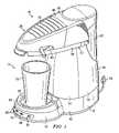
- FIG. 1is a perspective view of a coffeemaker incorporating features of the present invention
- FIG. 2is an exploded perspective view of the coffeemaker shown in FIG. 1 ;
- FIG. 3is an exploded perspective view of the hot water heater used in the coffeemaker shown in FIG. 2 ;
- FIG. 4is a partial perspective view of the top of the coffeemaker shown in FIG. 1 with the lid moved to an open position;
- FIG. 5is a perspective view of the combined locking and cam ring member shown in FIG. 2 ;
- FIG. 6is a partial perspective view as in FIG. 4 with the coffee pod carrier shown in an exploded position;
- FIG. 7is a bottom plan view of the funnel shown in FIGS. 2 and 6 ;
- FIG. 8is a top plan view of the pod carrier and funnel shown in FIGS. 4 and 6 ;
- FIG. 9is a cross sectional view of the pod carrier and funnel shown in FIG. 8 taken along line 9 — 9 ;
- FIG. 10is a perspective view of a coffee pod for use with the coffeemaker shown in FIG. 1 ;
- FIG. 11is a cross sectional view similar to FIG. 9 with the coffee pod carrier located in a reversed, flipped different position;
- FIG. 12is a cross sectional view of alternate embodiments of a coffee pod, coffee pod carrier, and funnel incorporating features of the present invention
- FIG. 13is an exploded perspective view of an attachment between the coffee pod carrier and funnel shown in FIG. 12 ;
- FIG. 14is a perspective view of the coffeemaker shown in FIG. 1 with an optional elevation attachment for use with a smaller cup;
- FIG. 15is a partial, exploded perspective view of the optional elevation attachment shown in FIG. 14 and the support section of the housing of the coffeemaker
- FIG. 16is a partial cross-sectional view of the pod carrier and the seal before the seal is compressed
- FIG. 17is a partial cross-sectional view of the pod carrier and the seal after the seal is compressed
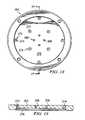
- FIG. 18is a bottom plan view of a bottom plate of one embodiment of the hot water discharge head.
- FIG. 19is a cross sectional view of the plate shown in FIG. 18 taken along line 19 — 19 .
- FIG. 1there is shown a perspective view of a brewing apparatus 10 incorporating features of the present invention.
- a brewing apparatus 10incorporating features of the present invention.
- the present inventionwill be described with reference to the exemplary embodiment shown in the drawings, it should be understood that the present invention can be embodied in many alternate forms of embodiments.
- any suitable size, shape or type of elements or materialscould be used.
- a similar brewing apparatusis described in U.S. Patent application No. 60/327,538 filed Oct. 5, 2001; U.S. patent application Ser. No. 10/260,045 filed Sep. 30, 2002; and PCT application No. PCT/US02/30565 which are hereby incorporated by reference in their entireties.
- the brewing apparatus 10comprises a coffeemaker.
- the brewing apparatuscould comprise any suitable type of brewing apparatus such as, for example, a cappuccino maker or a tea maker.
- the coffeemaker 10generally comprises a housing 12 , a hot water heater 14 , a controller 16 , a pump 18 , a pod receiving section 20 , and a water reservoir 22 .
- the coffeemakeris a single serve coffeemaker. More specifically, the coffeemaker is adapted to make a single serving of coffee at a time, such as a single cup or mug.
- the coffeemaker 10is adapted to be plugged into an electrical outlet by a removable plug 24 .
- the water reservoir 22is removable from the housing 12 .
- the coffeemakermight not include a removable water reservoir, such as when the coffeemaker is connected directly to a water supply line or if the water reservoir is non-removable.
- the water reservoir 22includes a seal 26 for removably coupling the water reservoir with an inlet 28 to the pump 18 .
- the pump 18includes an outlet 30 which is connected by tubing 31 to an inlet 32 of the hot water heater 14 .
- the pump 18preferably comprises a direct drive solenoid pump which can vary the flow rate of water therethrough by adjustably controlling the speed of the pump. In alternate embodiments, any suitable type of pump could be used.
- the pump 18is connected to the controller 16 .
- the controller 16comprises a printed circuit board 34 with a processor 36 and control switches 38 .
- the controller 16is adapted to control the speed of the pump 18 based upon sensor input, input from the control switches 38 , and pre-programming.
- the controller 16is also adapted to control activation of the hot water heater 14 . More specifically, the controller 16 is connected to a relay 44 for controlling the supply of electricity to the hot water heater 14 .
- the housing 12forms a general frame for the coffeemaker. As seen in FIG. 1 , the housing 12 includes a base section 42 , a column section 44 , and a top section 46 .
- the column section 44is supported on a rear portion of the base section 42 .
- the pump 18is mounted on top of the base section 42 with the column section 44 surrounding the pump 18 .
- the base section 42forms a forward extending section 48 .
- the controller 16is located inside the base section 42 with the control switches 38 extending out of apertures at the front end of the forward extending section 48 .
- the top side of the forward extending section 48forms a support surface 50 .
- the support surface 50is adapted to support a cup or container 52 , such as a cup or mug, or any other type of liquid single user container, thereon.
- the support surface 50can be flat or in a recess 51 , or recessed as shown in FIG. 2 .
- the sidewalls which form the recess at the support surface 50comprise overflow slots 54 .
- the overflow slots 54allow the fluid to flow out of the recess, in the event fluid overflows into the recess, and prevents the overflowing fluid from overflowing onto the user control section 56 having the control switches 38 .
- the slots 54can also be used to support attachment of a removable elevated cup support platform 244 (see FIG. 14 ) as further described below.
- the coffeemakeralso comprises a system 58 for detecting when an overflow condition has occurred.
- the system 58includes a tube 60 which is connected to the pump 18 or a sensor. A front end of the tube 60 extends into the recess 51 at the support surface 50 . In the event the recess fills with fluid, the tube 60 can transport some of the fluid in the tube to the pump or a sensor to signal the overflow condition. The pump 18 and/or the controller 16 can then automatically deactivate the pumping action of the pump 18 to prevent further overflow.
- any suitable type of overflow sensing systemcould be provided. In another alternate embodiment, an overflow sensing system might not be provided.
- the column section 44 of the housingsupports the hot water heater 14 in a front section 62 .
- the column section 44also has a receiving area 64 for removably receiving the water reservoir 22 .
- FIG. 3an exploded perspective view of the heater 14 is shown.
- the heater 14generally comprises a water heating subassembly 118 , heat shield members 120 , 122 , thermal cutoffs (TCO) 124 , a TCO clip 126 , a thermistor 128 , a thermistor clip 130 , top and bottom water tube fittings 132 , 134 , and top and bottom end caps 136 , 138 .
- TCOthermal cutoffs
- the heatercould comprise additional or alternative components.
- the thermistoris used to measure the temperature of the hot water generator for determining an end of a pre-heat cycle and, to help insure that the hot water generator is at a temperature for generating the hot water in a temperature range to provide proper brewing and a preferred coffee temperature. If too hot, the power to the heating elements can be turned OFF. If too cool, the pump can be stopped or its speed lowered.
- the thermistoralso provides over-temperature sensing, such as when water flow to the heater stops (such as when the water reservoir becomes empty).
- the coffeemakeralso comprises a temperature sensor 70 (see FIG. 2 ) connected to the tubing 31 .
- the temperature sensor 70can sense the temperature of the water entering the inlet 32 of the heater 14 . In an alternate embodiment, the temperature sensor 70 could be located connected to the tube 68 for measuring the temperature of the water exiting the heater 14 .
- the water heating subassembly 118generally comprises a water conduit tube 140 , two heating elements 142 , and blocks 144 of heat conductive material which connect the heating elements 142 to the water conduit tube 140 .
- the two heating elements 142are Calrods. However, in alternate embodiments, any suitable type of heating element could be used. In addition, more or less than two heating elements could be used.
- the tube 140 and the blocks 144are formed as a single extruded aluminum member.
- the heating elements 142are connected to the one-piece member after it is formed.
- the inside of the tube 140comprises one or more heat transfer fins 141 . However, in an alternate embodiment, the fins 141 might not be provided.
- any suitable type of internal heat transfer memberscould be provided inside the tube 140 .
- Formation of the tube 140 as an extruded membermakes formation of heat transfer members inside the tube relatively easy.
- the blocks 144 of heat conductive materialare comprised of cast aluminum and are subsequently connected to the tube.
- the blocks 144could be comprised of any suitable type of material.
- more or less than two blockscould be used.
- Blocks 144function as mechanical attachments for the heating elements 142 to the water conduit tube 140 .
- the blocks 144also function as heat transfer elements to transfer heat from the heating elements 142 to the water conduit tube 140 .
- the heating elements 142are connected to the relay 40 which is controlled by the controller 16 .
- any suitable type of water heating subassemblycould be provided.
- the TCO 124 and the thermistor 128are mechanically attached to the subassembly 118 by the two clips 126 , 130 .
- any suitable meanscould be used to attach the TCO 124 and the thermistor 128 to the subassembly 118 .
- the TCO 124 and/or the thermistor 128could be integrally formed with the subassembly 118 .
- the TCO 124 and the thermistor 128are operably electrically connected to the controller 24 .
- any suitable type of a temperature sensor or thermal fusecould be provided.
- the shield members 120 , 122 and end caps 136 , 138substantially surround the water heating subassembly 118 .
- the two fittings 132 , 134are connected to opposite ends of the water conduit tube 140 .
- the bottom tube fitting 132is connected to the tubing 31 .
- the top tube fitting 134is connected to a hot water discharge head 66 by a tube 68 (see FIG. 2 ).
- the heater 14is orientated in a substantially vertical orientation with its water inlet 32 at its bottom end and its heated water outlet at its top end.
- the heatercould be orientated in any suitable orientation.
- the heater in this embodimenthas a substantially straight shape.
- the heatercould have any suitable type of shape, such as L shaped for example.
- the water being pushed upward into the inlet 32contacts the entire inner diameter surface of the water conduit tube 140 .
- the wateris retained in the water conduit tube 140 by gravity until the water is pushed out of the top outlet at fitting 134 by new incoming water. This ensures maximum heat transfer to the water in the water conduit tube 140 before the water flows out of the top outlet fitting 134 .
- the heateris a 1400 Watt heater at 120 Volts.
- any suitable heatercould be provided.
- a 1400 Watt heaterallows the heater to be able to increase in temperature from room temperature to heat water to 180° F. within one minute.
- temperature sensorscould be provided in the water reservoir and/or at the outlet from the heater for more precise hot water generation.
- power from the power companycan fluctuate, such as during a brownout. Manufacturing tolerances for the heater are preferably +5% to ⁇ 10% Wattage variation.
- the heaterwould have an output of 1950 Watts, and at 107 Volts the heater would have an output of 1100 Watts.
- the present inventionrecognizes this and uses the controller to compensate by controlling operation of the pump and heater.
- the thermistor 128 and temperature sensor 70monitor the hot water generator and the incoming water temperature, and sends signals to the controller 16 such that the controller can take action to adjust or correct the temperature of the water while the water is still inside the hot water generator.
- This controldelivers a relatively accurate desired temperature of the hot water. This results in the best predetermine quality of brewed coffee even though the supply of electricity or the initial water temperature may not always be the same.
- the controllercan control the heater 14 and the pump 18 , based at least partially upon the temperature of the heater sensed by the thermistor 128 and the temperature of the incoming water sensed by the temperature sensor 70 .
- the controller 16can be programmed to, at least initially, control the speed of the pump 18 based upon the incoming water temperature as sensed by the temperature sensor 70 .
- the use of two sensors 70 , 128can also do away with the pre-heating cycle, or at least reduce the pre-heating cycle.
- the controller 16is programmed to control the speed of the pump 18 based upon the temperatures sensed by the two sensors 128 , 70 .
- the programming of the controller 16can comprises an algorithm or a lookup table, for example.
- the controller 16performs a pre-heat cycle of the heater before the pump 18 is actuated, such as about one minute.
- a pre-heat cyclemight not be provided.
- the pre-heat cyclecould be longer or shorter than one minute, such as merely 10 seconds for example when the speed of the pump 18 is initially set at a slow speed while the heater is being initially heated.
- the pump 18is not turned ON until the heater 14 has reached a predetermined minimum temperature. After the predetermined minimum temperature is reached, the controller 16 then actuates the pump 18 to start pumping water into the heater. However, the speed of the pump 18 does not need to be constant as explained above.
- the controllercontinuously monitors the temperature of the heater and the inlet water.
- the controllershuts the heater OFF, but continues pumping water through the pump to the heater. If the temperature of the heater goes below a predetermined out-of-range lower temperature, the controller shuts the pump OFF until the temperature of the heater rises again. Then, the pump is turned ON again.
- the controllercould turn the pump ON without use of the pre-heat cycle; such as when a user starts the coffee maker when the temperature of the heater is between the out-of-range lower and upper temperatures.
- the out-of-range lower and upper temperaturescould be fixed or could be varied based upon predetermined conditions, such as pod recognition or coffee maker system state.
- the top section 46 of the housing 12comprises a stationary section 72 and a movable lid 73 .
- the top section 46is connected to the top of the column section 44 .
- the top section 46extends outward in a general cantilevered fashion from the top of the column section 44 . More specifically, the top section 46 extends outward over the forward extending section 48 of the base section 42 . This forms a cup receiving area 74 between the support surface 50 and the top section 46 .
- the stationary section 72comprises a top section 76 and a bottom section 78 .
- the bottom section 78comprises two members 80 , 82 (see FIG. 2 ).
- the two members 80 , 82form an internal area which houses a switch 84 .
- the switch 84is connected to the controller 16 .
- the stationary section 72forms an aperture 86 for receiving various components as further described below.
- the movable lid 73is pivotably connected to the stationary section 72 .
- a brewing areais formed under the lid 73 when the lid is located at a closed, down position.
- the lid 73comprises a main lid member 88 and an assembly 90 .
- the main lid member 88comprises two rearwardly extending pivot arms 92 .
- the rear ends of the pivot arms 92are pivotably attached to the rear end of the stationary section 72 at the top rear of the housing 12 .
- Springs 146could be provided to bias the lid 88 in the open position shown in FIG. 4 .
- the spring(s)could bias the lid in the closed position shown in FIG. 1 .
- a spring for the lid 73does not need to be provided.
- the lid 73could comprise a latch (not shown) for latching the lid in a closed position with the stationary section 72 .
- the main lid member 88could comprise a resilient deflectable latch.
- the latch for retaining the lid in the closed positioncould be mounted on the stationary section 72 and adapted to engage the main lid member 88 .
- One side of the main housing member 88comprises a slot 94 .
- the assembly 90generally comprises the hot water discharge head 66 , a seal 96 , a combined locking and cam ring member 98 , and a mounting member 100 .
- the discharge head 66has a general showerhead design.
- the hot water discharge head 66generally comprises a top water inlet 102 , mounting flanges 104 , an internal plenum 106 , and bottom side outlet apertures 108 (see FIG. 4 ).
- the inlet 102is connected to the tube 68 from the hot water heater 14 .
- the mounting flanges 104are used to stationarily attach the discharge head 66 to the main lid member 88 .
- the outlet apertures 108allow hot water to exit the discharge head in a downward direction.
- the outlet apertures 108are arranged to deliver a greater quantity of water towards the outer perimeter than the center of the bottom side of the discharge head.
- any suitable type of array or configuration of the outlet aperturescould be provided.
- any suitable type of discharge headcould be provided.
- the seal 96is attached to the bottom side of the discharge head 66 at its outer perimeter.
- the seal 96comprises an O-ring seal.
- the mounting member 100is located above the top side of the discharge head 66 , and is adapted to slidably rotate on the top side of the discharge head.
- the ring member 98is fixedly attached to the mounting member 100 .
- the ring member 98extends below the discharge head 66 and is adapted to rotate relative to the discharge head 66 due to its suspended connection with the mounting member 100 .
- the ring member 98generally comprises a handle 110 and a center ring section 111 .
- the center ring section 111generally comprises a main center aperture 113 , three equi-spaced locking projections 112 , two opposing slots 114 , and two opposing cam surfaces 116 .
- the locking projections 112extends downward from the ring section.
- the slots 114are located along an interior side of the ring section at the main center aperture 113 .
- the cam surfaces 116are located adjacent the slots 114 .
- the handle 110extends out of the slot 94 in the main lid member 88 . The handle 110 can move in the slot 94 as the ring member 98 is rotated.
- a usercan moved the handle to rotate the ring member 98 between a locked position (shown in FIG. 1 ) and an unlocked position (shown in FIG. 4 ).
- the hot water discharge head 66remain stationary as the ring member 98 is rotated between its locked and unlocked positions.
- the stationary section 72comprises slots 148 along the aperture 86 to allow the locking projections 112 of the ring member 98 to pass therethrough.
- the lid 73is located in its down, closed position and the ring member 98 is rotated to its locked position, bottom portions of the locking projections 112 are moved beneath portions of the stationary section 72 to latch the lid 73 in its closed position.
- the locking projections 112can once again be passed through the slots 148 to allow the lid 73 to be moved back to its open position.
- any suitable type of locking systemcould be provided.
- the coffeemaker 10includes a pod carrier 150 and a discharge funnel 152 .
- the carrier pod 150 and the discharge funnel 152are adapted to be removably connected to the stationary section 72 at the aperture 86 .
- the funnel 152generally comprises an upper circular wall section 154 , a lower cone-shaped wall section 156 , and an outlet 158 at the bottom center of the lower cone-shaped wall section 156 .
- the upper wall section 154includes slots 164 (see FIGS. 2 and 4 ). The slots 164 are provided to accommodate projections on the pod carrier 150 as further described below.
- the funnel 152includes support ledges 160 extending outward from a top side of the upper wall section 154 .
- Keying sections 162extends downward from the support ledges 160 .
- the stationary section 72includes slots for receiving the keying sections 162 , and the support ledges 160 are adapted to be supported on a top side of the stationary section 72 at the aperture 86 .
- the funnel 152can be dropped into the aperture 86 with the support ledges 160 supporting the funnel on the stationary section and the keying sections 162 aligning the funnel in the aperture 86 in a predetermined position.
- the pod carrier 150generally comprises a frame 166 and a center support 168 .
- the frame 166comprises a one piece member made of molded plastic or polymer material.
- the center support 168preferably comprises a metal screen member. However, in alternate embodiments, any suitable type of center support could be provided.
- the frame 166is preferably over molded onto the outer perimeter of the center support 168 . This fixedly attaches the center support 168 to the frame 166 . However, in alternate embodiments, any suitable attachment system could be used.
- the center support 168provides three functions. First, the center support 168 divides the frame 166 into two sections; each section having a distinct pod receiving area.
- the center support 168provides a path to allow fluid to flow through the center support from one pod receiving area to the other pod receiving area.
- the center support 168helps to provide a support surface for supporting a pod of material in either one of the two pod receiving areas as further described below.
- the frame 166includes a handle 170 , a first pod receiving area or cavity 172 , a second pod receiving area or cavity 174 , and two sets of lateral extending cam projections 176 , 178 .
- the two pod receiving areas 172 , 174are separated from each other by the center support 168 .
- the two pod receiving areas 172 , 174are adapted to receive pods 180 , one of which is shown in FIG. 10 .
- the pod 180generally comprises a porous casing 182 and an interior area comprising material to be brewed, such as coffee grounds 184 .
- the casing 182is comprised of a material similar to coffee filter paper.
- Each pod 180is preferably a single serve pod; i.e., each pod can be used to generate a single serving, such as one cup, of coffee.
- the first pod receiving area 172has a first open entrance aperture on a first side of the frame, and the first pod receiving area is sized and shaped to receive one of the coffee pods 180 .
- the second pod receiving area 174is about twice as large as the first pod receiving area 172 .
- the second pod receiving area 174has a second open entrance aperture on a second side of the frame, and the second pod receiving area is sized and shaped to receive two of the coffee pods 180 ; one pod stacked on top of the other pod inside the receiving area.
- a single larger coffee podcould be positioned into the second pod receiving area 174 .
- the coffee pod(s) 180are held in the first or second pod receiving areas 172 , 174 merely by gravity; at least before the lid 73 is moved to its closed position.
- the first pod receiving area 172can receive and hold one of the pods 180 only when it is orientated facing a top side of the pod carrier 150 .
- the second pod receiving area 174can receive and hold two of the pods 180 only when it is orientated facing the top side of the pod carrier 150 .
- the pod carrier 150is adapted to be flipped 180 degrees to hold either one pod 180 in the first pod receiving area 172 or two pods 180 in the second pod receiving area 174 .
- the frame 166 of the pod carrier 150has an first open aperture on a first side at the first pod receiving area 172 and a second open aperture at a second side of the second pod receiving area 174 .
- the frame 166forms a surrounding perimeter wall 186 forming two inwardly facing sealing surfaces 188 , 190 and two inwardly extending shells 192 , 194 located at a bottom of the sealing surfaces 188 , 190 , respectively.
- the entrance apertures into the first and second pod receiving areasare defined by the perimeter wall.
- the outer rim 196 of the bottom coffee podcan flex upward against the sidewalls inside the second pod receiving area 174 , and the outer rim 196 of the top coffee pod can sit against the shelf 194 .
- the bottom of the bottom coffee podwould sit against one side of the mesh screen 168 .
- the coffee pod carrieris shown flipped 180 degrees relative to its position shown in FIG. 9 . In this position, the first coffee pod receiving area 172 is located at the top of the coffee pod carrier 150 .
- One of the coffee pods 180can be located in the first coffee pod receiving area 172 with its outer rim 196 located against the shelf 192 and the bottom of the coffee pod being located against one side of the mesh screen 168 .
- the handle 170extends outward along a plane proximate a junction of the first and second pod receiving areas; slightly more toward the larger second pod receiving area than the first pod receiving area.
- the coffee pod carrier 150is adapted to be removably inserted into the top side of the funnel 152 when the lid 73 is located in its open position.
- FIGS. 4 , 6 and 9illustrate the position of the coffee pod carrier 150 into the funnel 152 inside the stationary section 72 with the second pod receiving area 174 located in the top position.
- the first set of cam projections 176slide into the slots 164 in the funnel and come to rest on the bottom sides of the slots. Because the funnel 152 is supported on the stationary section 72 by its support ledges 160 , the pod carrier 150 is therefore supported on the stationary section 172 by the funnel 152 .
- the second set of cam projections 178would be received in the slots 164 and rest against the bottom of the slots.
- the handle 170is positioned in a front recess of the stationary section 72 for relatively easy grasping by a user to remove the pod carrier after use and dispose of a hot coffee pod(s) located in the carrier without the need for touching the hot coffee pod(s).
- the top side of the pod carrierextends above the funnel as shown in FIGS. 4 and 9 .
- the cam projections 178pass through the slots 114 (see FIG. 5 ) in the ring member 98 .
- the bottom side of the hot water discharge head 66 and the seal 96extend slightly into or just above the top aperture into the second pod receiving area 174 .
- the lid 73comes down on the pod carrier 150 at a very small angle; almost vertically, such as about merely five degrees of rotation between when the bottom of the seal 96 is located proximate the top of the aperture into the second receiving area 172 and when the lid 73 reaches its closed position.
- the inner top side of the surrounding perimeter wall 186is curved to substantially prevent wear on the seal 96 when the lid 73 is merely moved to its closed position and before the pod carrier 150 is moved upward as explained below.
- the ring section 111rotates, and the cam surfaces 116 engage the bottom surfaces of the cam projections 178 to cam the pod carrier 150 in an upward direction.
- the outer rim 196 of the top coffee pod 180 in the second pod receiving area 174is sandwiched or captured between the shelf 194 and the seal 96 . This helps to clamp the pod to prevent it from moving, and to prevent hot water from the discharge head 66 from passing around the outer side of the top pod 180 without passing through the pod.
- the seal 96is vertically compressed and expands or deforms in an outward direction. As the seal 96 expands outwardly, it engages the sealing surface 190 on the inner side of the perimeter wall 186 at the second receiving area 174 . This seals the pod carrier frame 166 with the hot water discharge head 66 such that water discharged from the discharge head 66 must pass through the second pod receiving area 174 in order to exit through the mesh screen 168 .
- the seal 96also helps to clamp the rim 196 against the surface 194 to hold the rim in a stationary position. However, the sealing action is provided between the surface 190 (or 188 ) and the head 66 by the seal 96 .
- the brewed coffeeWhen the brewed coffee exits through the mesh screen 168 it flows through the first pod receiving area 172 and onto the inner surface of the discharge funnel 152 at the lower cone-shaped wall section 156 .
- the brewed coffeecan flow to the outlet 158 and flow out of the funnel 152 as a stream into the cup 52 located on the support surface 50 .
- the funnel 152has a relatively high upper wall section 154 , the bottom side of the pod carrier 150 stays inside the funnel when the pod carrier is moved upward by the ring member 98 . This ensures that the brewed coffee exits the pod carrier into the interior of the funnel even though the pod carrier has been vertically moved relative to the funnel.
- the pod carrier 150is inserted into the funnel 152 with the first pod receiving area 172 located in the top position as shown in FIG. 11 , the pod carrier 150 is located in the funnel 152 with the top side of the pod carrier extending above the funnel.
- the cam projections 176past through the slots 114 (see FIG. 5 ) in the ring member 98 .
- the bottom side of the hot water discharge head 66 and the seal 96extend slightly into or just above the top aperture into the first pod receiving area 172 .
- the inner top side of the surrounding perimeter wall 186 at the first pod receiving area 172is curved to substantially prevent wear on the seal 96 when the lid 73 is merely moved to its closed position and before the pod carrier 150 is moved upward as explained below.
- the ring section 111rotates and the cam surfaces 116 to engage the bottom surfaces of the cam projections 176 to cam the pod carrier 150 in an upward direction.
- the outer rim 196 of the coffee pod 180 in the first receiving area 172is clamped between the shelf 192 and the seal 196 . This helps to prevent the pod from moving and to prevent hot water from the discharge head 66 from passing around the outer side of the pod 180 in the first receiving area 172 without passing through the pod.
- the seal 96is vertically compressed and expands or deforms in an outward direction.
- the coffeemakerhas a system for varying water temperature of water exiting the heater.
- the systemcomprising the controller coupled to the sensors.
- the pumpis a variable speed pump. Power, when the hot water heater is ON, is supplied as a substantially fixed non-varying power, and the controller is adapted to provide hot water from the heater at either a first temperature or a second higher temperature based upon speed of the pump without varying power supply to the heater.
- the systemcould be configured to deliver hot water at more or less than two temperatures.
- Consistently repeatable good quality brewed liquidrequires accurate hot water quantity delivery and relatively precise hot water temperature.
- Conventional coffeemakersadjust the hot water heat to control water temperature.
- temperature controlespecially in a single serve brewing apparatus dispensing a relatively small quantity of water such as only about seven to twelve ounces, is not good and does not produce consistently repeatable good quality brewed liquid.
- the present inventionprovides a better control system for water temperature for a small serve brewing apparatus, such as an individual serving dispenser coffeemaker.
- the usercan rotate the handle 110 back to its unlocked position and open the lid 73 .
- the usercan then grasp the coffee pod carrier 150 at the handle 170 to remove the coffee pod carrier and dispose of the used coffee pod(s).
- One of the features of the present inventionis a reduced amount of wear on the seal 96 . More specifically, the seal 96 does not run up against any of the components when it is being inserted into or removed from the aperture in the pod carrier. Only after the seal is located in the aperture in the pod carrier is it deformed to perform its sealing function.
- the perimeter sealing feature described abovereduces wear on the seal 96 to prevent steam or water vapor from exiting from the pod brewing chamber without passing through the coffee pod. This helps to maintain an accurate and predictable good brewed coffee quality.
- the coffeemakercomprises a switch 84 (see FIG. 2 ) located in the stationary section 72 .
- the ring member 98comprises a section which is adapted to actuate the switch 84 when the ring member 98 is moved to its locked position.
- the ring member 98is adapted to deactuate the switch 84 when the ring member is moved away from its locked position.
- the switch 84is connected to the controller 16 .
- the controller 16knows that the ring member 98 is at its locked position. If the user moves the ring member 98 from its locked position during a brewing cycle, the controller 16 is programmed to deactivate the heater 14 .
- the pump 18will continue to flow water out of the discharge head 66 , but the water is prevented from being converted into potentially harmful steam because the heater 14 has been turned OFF and, the continuing flow of water through the heater 14 prevents water from standing in the heater and turning into steam.
- any suitable type of signaling system or any suitable type of system for preventing a user from being potentially harmed by steamcould be provided.
- the controllercould be programmed to continue pumping of water through the heater until the heater reached a predetermined relatively cool temperature.
- the controllercould be programmed to continue pumping of water through the heater for a predetermined amount of time after the switch is deactuated or after the heater is turned OFF.
- the control systemcould also comprise an electromagnetic solenoid 260 having an extendable shaft 262 .
- the solenoidwould be connected to the controller 16 .
- the shaft 262would normally be retracted at a home position when the solenoid is not actuated.
- the controlleractivated the solenoid to move the shaft 262 forward and into engagement with the member 98 . This engagement results in the member 98 no longer being able to rotate away from its locked position.
- the control systemforms a lock to prevent the user from opening the lid 73 during a brewing cycle.
- the controller 16can deactivate the solenoid 260 , thereby removing engagement between the shaft 262 and the member 98 , and the user can now rotate the member 98 to allow the lid to be opened again.
- the controllermight be programmed to move the solenoid to an unlocked position after an end of a purge cycle of the brewing cycle to allow a purge of water and steam from the heater into the brewing chamber before the lid can be moved to an open position.
- any suitable type of locking systemcould be provided.
- FIG. 12shows a cross sectional view of a second type of pod carrier 198 , a funnel and mixing or frothing attachment 200 , and a second type of pod 202 .
- the second type of pod 202in this embodiment, is a creamy coffee pod.
- the creamy coffee pod 202comprises an outer casing 182 , a plastic or hard paper divider 204 which forms a first chamber 206 and a second chamber 208 , coffee grounds 184 located in the first chamber 206 and a powdered nondairy creamer 210 located in the second chamber 208 .
- the divider 204is adapted to allow fluid to flow therethrough, but otherwise substantially separates the coffee grounds 184 from the nondairy creamer 210 .
- the divider 204extends to the outer rim 212 where the top and bottom sides of the casing 182 are connected to the divider 204 .
- the podcould have more than one divider, and nondairy creamer might not be provided such as when the chambers of the pod merely comprise different types of coffee grounds, such as one or more different flavored coffee grounds.
- the pod carrier 198generally comprises a handle 214 , a pod receiving area 216 , and a lower chamber 218 .
- the pod receiving area 216is adapted to receive the pod 202 .
- the pod receiving area 216includes a shelf 220 and a sealing surface 222 on an inwardly facing perimeter side.
- the pod carrier 198is adapted to be inserted into the aperture 86 in the stationary section 72 as a replacement component for the pod carrier 150 .
- the funnel 152is not used.
- the funnel 152is removed from the aperture 86 .
- the funnel and mixing attachment 200is attached to the bottom end of the pod carrier 198 as further described below.
- the shelf 220 and sealing surface 222function substantially the same way as the shelves 192 , 194 and sealing surfaces 188 , 190 described above with reference to the pod carrier 150 .
- the ring member 98can be rotated to its locked position to move the pod carrier 198 to an upward position.
- the seal 96is clamped between the top side of the outer rim 212 and the hot water discharge head to cause the seal to expand outward against the sealing surface 222 . Because of the porous nature of the casing 182 , a good seal cannot be formed against the casing 182 at the shelf 212 .
- the seal 96is used to seal against the sealing surface 212 and substantially prevent steam or hot water vapor from exiting from the pod receiving area 216 without passing through the pod 202 .
- the seal 96helps to clamp the pod 202 in the pod receiving area 216 such that the pod does not move or float in the event the pod receiving area 216 becomes substantially filled with water.
- the pod carrier 198includes a metal mesh screen 168 , such as a screen having the plastic portion of the pod carrier over molded thereonto.
- the screenmight not be metal, such as a molded plastic screen, and the screen could be attached to the frame of the pod carrier by any suitable means.
- the lower chamber 218is located beneath the screen 168 and allows brewed coffee and nondairy creamer to mix therein before exiting a bottom outlet 224 .
- the main housing 226 of the pod carrier 198includes mounting projections 228 on a lower exterior side and cam lugs 176 at a top side.
- the cam lugs 176can work with the member 98 the same way that the cam lugs work on the pod carrier 150 .
- the mounting projections 228are provided to allow the funnel and mixing attachment 200 to be removably connected to the bottom end of the pod carrier 198 .
- any suitable system for removably attaching the attachment 200 to the pod carrier 198could be provided.
- the attachment 200is screwed, twisted or rotated onto the bottom of the pod carrier 198 .
- the two members 198 , 200could be connected by a caming connection.
- the funnel and mixing attachmentcould be formed integrally with the pod carrier rather than being removably connected.
- the funnel and frothing attachment 200comprises a main housing 230 and a mixing or frothing insert 232 .
- the main housing 230includes a top end with mounting apertures 234 and a bottom end with an outlet 236 .
- the mounting apertures 234are adapted to receive the mounting projections 228 therein to fixedly but removably attach the main housing 230 to the main housing 226 .
- the mixing insert 232comprises a plate having apertures 238 therethrough.
- the mixing insert 232divides the main housing 230 into two chambers 240 , 242 . At least the first chamber 240 forms a frothing chamber.
- the mixing insert 232is adapted to sit against interior sidewalls of the frame in the chamber.
- the mixing insert 232is preferably removably located in the chamber for easier cleaning.
- coffee and nondairy creamerexit from the lower chamber 218 from the bottom outlet 224 of the pod carrier 198 , they enter the chamber 240 and contact the mixing insert 232 .
- the chamber 240 and mixing insert 232allow the coffee and nondairy creamer to mix again, more thoroughly, in the chamber 240 .
- the coffee and nondairy creamercan flow through the apertures 238 into the chamber 242 , with additional mixing or frothing occurring, and exit the outlet 236 as a mixed stream of coffee and creamer directly into a user's cup.
- the mixingis done automatically in the chambers 218 , 240 and 242 ; the three chambers each forming frothing chambers.
- the pod carrier 198 and funnel and mixing attachment 200cause a slight time delay in the flow of liquid therethrough. This allows froth or foam generated from the mixing to at least slightly settle. Thus, because of this slight time delay, it may be preferred to have the temperature of the water entering the pod carrier 198 from the heater to be slightly higher in temperature than normal to compensate for heat lost during this time delay.
- a brewing apparatus pod carrier and mixing devicewhich includes a pod receiving section open at a top side of the device, a first mixing section located below the pod receiving section and adapted to receive brewed liquid from a first outlet of the pod receiving section, and a second mixing section located below the first mixing section and adapted to receive the brewed liquid from a second outlet from the first mixing section.
- the devicecan include the two mixing sections arranged in series. The second outlet of the first mixing section is small relative to the first outlet of the pod receiving section such that the brewed liquid will partially mix in the first mixing section before passing through the second outlet to the second mixing section.
- the coffeemaker 10is provided with an additional, optional attachment 244 for accommodating the positioning of a smaller cup 246 .
- the attachment 244is a booster seat or elevated cup platform.
- the cup 52 shown in FIG. 1is sized and shaped to receive at least twelve ounces of brewed coffee. Twelve ounces of brewed coffee can be generated by the coffeemaker 10 with the use of two of the coffee pods 180 and the pod carrier 150 having been positioned as shown in FIGS. 4 and 9 .
- a smaller cup of coffeesuch as seven ounces with the smaller coffee cup 246 shown in FIG.
- the attachment 244is provided to allow the smaller coffee cup 246 to be located at an elevated position relative to the support surface 50 .
- the elevation attachment 244generally comprises a bottom end 248 , a top surface 250 , and stabilizing supports 252 .
- the attachment 244has a general truncated cone shape with the bottom end 248 being larger than the top surface 250 .
- a side wallconnects the top and bottom sides. In a preferred embodiment the side wall is about two or three or four inches high. However, any suitable height could be provided.
- the attachment 244is preferably a one piece member made of molded plastic or polymer material.
- the general cone shapeprovides stability to the attachment on the support surface 50 . However, any suitable shape can be provided.
- the bottom end 248is sized and shaped to fit in the recess 51 and against the support surface 50 .
- the bottom sideis adapted to be vertically lowered into the recess.
- the stabilizing supports 252are sized and shaped to be located in the slots 54 .
- the stabilizing supports 252help to stabilize the elevation attachment 244 and prevent it from pivoting or rotating while connected in the recess 51 .
- the top surface 250is sized and shaped to support the bottom surface of the smaller cup 246 thereon.
- the elevation attachment 244when the elevation attachment 244 is connected to the forward extending section 48 of the base section 42 , the elevation attachment 244 can allow a user to place the smaller size cup 246 on the attachment 244 at an elevated position closer to the outlet 158 of the discharge, funnel 152 (see FIG. 11 ).
- the pod carrier 150When brewing coffee for the smaller size cup 246 , the pod carrier 150 would be orientated as shown in FIG. 11 to receive only one pod in its top receiving area.
- the height of the elevation attachmentis preferably about three to four inches or more. However, any suitable height could be provided.
- the elevation attachmentcould also have a variable or reconfigurable height, or variable connection location to the housing of the coffeemaker.
- the housing and the booster seatare adapted to alternatively support the first larger cup 52 without use of the booster seat or the second smaller cup 246 with the use of the booster seat at about the same distance from the brewed coffee outlet from the exit funnel.
- One of the features of the present inventionis the reduced cost of the attachment 244 relative to the more complicated prior art devices. The reduced cost is possible because the attachment is merely a one-piece member, such as a molded member, and does not need any complicated connection to the frame of the coffeemaker. In addition, the attachment 244 is relatively easy to clean because of its simple structure, and can even be placed in an automatic dishwasher.
- the stabilizing supports 252might not be provided.
- the bottom sideforms a sole connection area with the brewing apparatus by merely being place on top of the brewed liquid container support surface 50 without any additional attachments.
- the coffeemaker 10comprises four of the control switches 38 .
- a first one of the control switches 38is actuated by a user when using a single pod 180 and the elevation attachment 244 for making a small cup of coffee.
- the pod carrier 150would be positioned as shown in FIG. 11 .
- the controller 16will control the heater 14 and pump 18 to supply about seven ounces of hot water through the pod carrier and out the outlet 158 . Based upon the speed of the pump 18 and the duration which the pump is pumping, the controller 16 can precisely measure the quantity of hot water which is being dispensed.
- a second one of the control switches 38is actuated by a user when using two of the pods 180 for making a larger cup of coffee, such as the twelve ounce cup 52 shown in FIG. 1 .
- the pod carrier 150would be positioned as shown in FIGS. 4 and 9 .
- the controller 16will control the heater 14 and pump 18 to supply about twelve ounces of hot water through the pod carrier and out the outlet 158 .
- a third one of the control switches 38is actuated by the user when using the pod 202 , pod carrier 198 and attachment 200 shown in FIG. 12 for making coffee having nondairy creamer.
- the controller 16When this third control switch is actuated, the controller 16 will control the heater and pump to supply about seven ounces of hot water through the pod carrier and out the outlet 236 .
- the speed of the pump 18 when brewing with the pod 202might be slower than the speed of the pump when the first or second control switches are actuated to allow the water to be heated to a higher temperature because the water will take longer to pass through the pod 202 then through one or two of the pods 180 .
- a fourth one of the control switches 38is actuated by the user to perform an override or reset of the controller 16 . For example, if the user presses a wrong one of the control switches, the user can press the fourth control switch to interrupt a brewing cycle. In alternate embodiments, any suitable type of user interactive control could be provided.
- the coffeemakercan operate in one of three brewing modes with the actuation of one of the first three user actuated switches 38 noted above.
- the actuation of the first switchcan cause the coffeemaker to dispense a first quantity of water at a first temperature.
- the actuation of the second switchcan cause the coffeemaker to dispense a second quantity of water at a second temperature.
- the second temperaturecould be the same as the first temperature or could be hotter or cooler than the first temperature.
- the actuation of the third switchcan cause the coffeemaker to dispense a third quantity of water at a third temperature.
- the third quantity of wateris preferably about the same as the first quantity of water. However, the third quantity of water could be more or less than the first quantity of water.
- the third temperatureis preferably hotter than the first and second temperatures. However, the third temperature could be the same as or cooler than the first or second temperatures.
- One of the features of the present inventionis the ability to use another mode of brewing.
- a usercan load the pod carrier 150 with two of the pods 180 . However, rather than pressing the user actuated switch 38 for twelve ounces of water, the user can actuate the switch 38 for seven ounces of water. This will result in an extra strong cup of seven ounces of coffee being brewed.
- Another mode of operationcould comprise the user loading the pod carrier 150 with two of the pods 180 . However, rather than pressing the user actuated switch 38 for seven or twelve ounces of water, the user can actuate the switch 38 for the creamy pod. This could result in a hotter and stronger cup of coffee, but perhaps more than seven ounces.
- the usercould also load the pod carrier with two different types of the pods 180 ; having different coffee grounds in each pod to produce a unique mixture or coffee blend.
- the usercould load one pod flavored with vanilla and a second pod flavored with hazelnut to produce a user configured blend; configured based upon user selection of different types of coffee pods.
- the present inventionwas described above comprising a removable coffee pod carrier and a reversible coffee pod carrier, features of the present invention could be used with a non-removable coffee pod carrier and/or a coffee pod carrier which is not intended to be reversible or re-orientatable.
- the coffee pod carriermight have more or less than two coffee pod receiving areas, such as only one coffee pod receiving area as shown in FIG. 12 .
- the funnelcould be integrally formed with the housing of the coffeemaker or the housing of the coffee pod carrier.
- any suitable type of movable lid for the coffeemakercould be provided.
- the seal 96could form a seal with the top side of the pod carrier, or the seal could form a seal with the outer perimeter side of the pod carrier. The seal could be located on the lid housing rather than on the hot water discharge head.
- the coffeemakercould comprise an electromechanical latch, such as a solenoid to prevent the ring 98 from being moved away from the locked position during a brew cycle and thereby prevent the lid from being moved to an open position during the brew cycle.
- the temperature of the heatercould be adjusted as well as the speed of the pump. Alternatively, the speed of the pump could be constant and the temperature of the heater could merely be adjusted.
- a brewing apparatuscomprising a system for varying water temperature of water exiting the heater.
- the systemcan comprise a controller coupled to sensors, wherein power when the hot water heater is ON is supplied as a substantially fixed non-varying power, and wherein the controller is adapted to provide hot water from the heater at either a first temperature or a second higher temperature based upon speed of the pump without varying power supply to the heater.
- a brewing apparatuscan be provided comprising a user input section connected to the controller.
- the user input sectioncan be adapted to allowed a user to select one of at least three brewing modes comprising a first mode having a first quantity of water delivered by the pump and the heater at a first temperature, a second mode having a second quantity of water delivered by the pump and the heater at a second temperature, and a third mode having a third quantity of water delivered by the pump and the heater at a third temperature.
- the first and second temperaturescan be equal, and the third temperature can be the same as or different from the first and second temperatures.
- the bottom plate 264generally comprises three sets of water discharge holes.
- a first set 266 of the holescomprises a first center array of smaller holes 268 .
- the first set 266 of smaller holes 268comprise four of the smaller holes arranged in a general box or diamond shape configuration. However, in alternate embodiments, any suitable number of smaller holes and any suitable pattern could be provided.
- the second set 270 of the holes and to the third set 272 of the holesform a second surrounding array of larger holes 274 .
- the second set 270 of larger holes 274comprise four of the larger holes arranged in a general box or diamond shape configuration similar to the pattern of the first set 266 of smaller holes.
- the second set 270 of larger holesis axially rotated about 45 degrees relative to the first set 266 of smaller holes.
- the third set 272 of larger holes to 274comprise four of the larger holes arranged in a general box or diamond shape configuration similar to the pattern of the first set 266 of smaller holes and aligned with the first set of smaller holes.
- the second set 270 and a third set 272form concentric rings of holes around the first set 266 .
- the larger holes 274are at least about 50 percent larger than the smaller holes 268 . In a preferred embodiment, the larger holes 274 are about 75 percent larger than the smaller holes 268 .
- hot water introduced into the plenum of the hot water discharge head 66is allowed to exit the plenum out the bottom outlet holes 268 , 274 . More of the hot water from the plenum exits the outer holes than the center holes for a total wetting of the coffee pod located beneath the bottom plate 264 and a substantially even removal of coffee from the coffee grounds in the pod.
- the bottom plate 264includes a recessed area 276 which is adapted to receive a portion of the coffee pod if necessary. However, the recessed area 276 preferably provides an area to allow hot water to migrate, at least partially, over a top surface of the coffee pod before entering the coffee pod. This also increases entire wedding of the coffee grounds inside the coffee pod and more even removal of coffee from the coffee grounds.
Landscapes
- Engineering & Computer Science (AREA)
- Food Science & Technology (AREA)
- Apparatus For Making Beverages (AREA)
Abstract
Description
Claims (20)
Priority Applications (4)
| Application Number | Priority Date | Filing Date | Title |
|---|---|---|---|
| US10/683,744US7017472B2 (en) | 2003-10-10 | 2003-10-10 | Brewing apparatus water temperature control |
| CA002482229ACA2482229A1 (en) | 2003-10-10 | 2004-09-20 | Brewing apparatus water temperature control |
| EP04023576AEP1522247A3 (en) | 2003-10-10 | 2004-10-04 | Brewing apparatus water temperature control |
| MXPA04009792AMXPA04009792A (en) | 2003-10-10 | 2004-10-07 | Brewing apparatus water temperature control. |
Applications Claiming Priority (1)
| Application Number | Priority Date | Filing Date | Title |
|---|---|---|---|
| US10/683,744US7017472B2 (en) | 2003-10-10 | 2003-10-10 | Brewing apparatus water temperature control |
Publications (2)
| Publication Number | Publication Date |
|---|---|
| US20050076788A1 US20050076788A1 (en) | 2005-04-14 |
| US7017472B2true US7017472B2 (en) | 2006-03-28 |
Family
ID=34314163
Family Applications (1)
| Application Number | Title | Priority Date | Filing Date |
|---|---|---|---|
| US10/683,744Expired - LifetimeUS7017472B2 (en) | 2003-10-10 | 2003-10-10 | Brewing apparatus water temperature control |
Country Status (4)
| Country | Link |
|---|---|
| US (1) | US7017472B2 (en) |
| EP (1) | EP1522247A3 (en) |
| CA (1) | CA2482229A1 (en) |
| MX (1) | MXPA04009792A (en) |
Cited By (31)
| Publication number | Priority date | Publication date | Assignee | Title |
|---|---|---|---|---|
| US20050247205A1 (en)* | 2004-05-06 | 2005-11-10 | Chen Andrew Y C | Single/multiple beverage machine |
| US20060283331A1 (en)* | 2005-06-20 | 2006-12-21 | Uni-Splendor Corp. | Coffee maker |
| USD544286S1 (en)* | 2005-01-04 | 2007-06-12 | Societe Des Produits Nestle S.A. | Milk machine |
| USD549520S1 (en)* | 2005-03-18 | 2007-08-28 | Hamilton Beach/Proctor-Silex | Coffee maker base |
| US20070261566A1 (en)* | 2006-05-08 | 2007-11-15 | Varney James R | Mixing and dispensing granular food products and liquid |
| USD556499S1 (en)* | 2006-01-31 | 2007-12-04 | Seb S.A. | Hot water dispenser for beverages |
| US20080216667A1 (en)* | 2007-03-09 | 2008-09-11 | Michael Garman | Brewed beverage maker |
| US20080302123A1 (en)* | 2004-12-31 | 2008-12-11 | Whirlpool Corporation | Disposable flavor insert for water dispenser |
| US20090229471A1 (en)* | 2008-03-17 | 2009-09-17 | Man Fai Lun | Two Cups Automatic Coffee Maker with Flow Control |
| US20100089339A1 (en)* | 2008-10-09 | 2010-04-15 | Krause Timothy D | System and method for controlling a pump in a recirculating hot water system |
| US20100260907A1 (en)* | 2009-04-08 | 2010-10-14 | Melitta SystemService GmbH & Co. KG | Method for the preparation of a fresh, cold, coffee-based beverage and a corresponding coffee machine |
| US20110265658A1 (en)* | 2009-01-14 | 2011-11-03 | Nestec S.A. | Modular system with small footprint autonomous module |
| US20120052171A1 (en)* | 2010-09-01 | 2012-03-01 | William D Starr | High powered, single serve, automatic drip brewed beverage maker and related scoop |
| WO2012039772A1 (en)* | 2010-09-21 | 2012-03-29 | Joseph Behm | System for precise temperature control of liquids in consumer products |
| USD666451S1 (en)* | 2010-08-26 | 2012-09-04 | Rocky Cheng | Espresso coffee machine |
| WO2013039590A1 (en)* | 2011-09-13 | 2013-03-21 | Conair Corporation | Brewed beverage appliance and method |
| US9114902B2 (en) | 2011-03-22 | 2015-08-25 | Polyone Designed Structures And Solutions Llc | Methods and systems for use in forming an article from a multi-layer sheet structure |
| WO2016072845A1 (en) | 2014-09-08 | 2016-05-12 | Innobizzer B.V. | System for making a hot beverage with substantially horizontal throughflow and method for making a hot beverage |
| US9427106B2 (en)* | 2009-04-01 | 2016-08-30 | Rancilio Group S.p.A. | Machine for infusion preparation, in particular espresso coffee, supplying group and manufacturing method thereof |
| WO2017031212A1 (en)* | 2015-08-18 | 2017-02-23 | Remington Designs, Llc | Beverage maker |
| US9700171B2 (en) | 2013-04-03 | 2017-07-11 | 2266170 Ontario Inc. | Capsule machine and components |
| USD823040S1 (en) | 2016-12-27 | 2018-07-17 | Hamilton Beach Brands, Inc. | Coffeemaker |
| US11083331B2 (en) | 2015-02-04 | 2021-08-10 | Hamilton Beach Brands, Inc. | Beverage maker |
| US11524268B2 (en) | 2016-11-09 | 2022-12-13 | Pepsico, Inc. | Carbonated beverage makers, methods, and systems |
| USD1034029S1 (en)* | 2018-10-03 | 2024-07-09 | LNJ Group, LLC | Upper portion of a beverage dispenser |
| USD1048793S1 (en) | 2023-05-02 | 2024-10-29 | Sharkninja Operating Llc | Coffee machine |
| USD1048792S1 (en) | 2023-04-12 | 2024-10-29 | Sharkninja Operating Llc | Coffee machine |
| US12171361B2 (en) | 2020-12-30 | 2024-12-24 | Sharkninja Operating Llc | Hybrid receptacle beverage brewing system |
| EP4442173A4 (en)* | 2021-12-03 | 2025-01-29 | LG Electronics Inc. | COFFEE MACHINE |
| EP4442174A4 (en)* | 2021-12-03 | 2025-01-29 | LG Electronics Inc. | COFFEE MACHINE |
| US12303063B2 (en) | 2020-12-11 | 2025-05-20 | Hamilton Beach Brands, Inc. | Beverage-making machine |
Families Citing this family (31)
| Publication number | Priority date | Publication date | Assignee | Title |
|---|---|---|---|---|
| ES1058642Y (en) | 2004-10-08 | 2005-05-01 | Quality Espresso S A | COFFEE PREPARATION MACHINE WITH ELECTRONIC TEMPERATURE CONTROL. |
| US7401545B2 (en)* | 2004-11-09 | 2008-07-22 | Nestec S.A. | Method and apparatus for optimizing variable liquid temperatures |
| US20080190298A1 (en)* | 2005-05-17 | 2008-08-14 | Tenacta Group S.P.A. | Appliance For Producing Hot Drinks |
| EP1899656A2 (en)* | 2005-06-20 | 2008-03-19 | CN Energy Developments A/S | A solar water heating system |
| AU2006332444B2 (en)* | 2006-01-05 | 2013-02-28 | Breville Pty Limited | Automated dose control for espresso maker |
| WO2008007278A1 (en)* | 2006-07-11 | 2008-01-17 | Koninklijke Philips Electronics N.V. | Method for controlling a quantity of water to be used for the purpose of obtaining a quantity of hot liquid |
| EP2027798A1 (en)* | 2007-08-20 | 2009-02-25 | Nestec S.A. | Beverage production module and method for operating a beverage production module |
| ATE539261T1 (en)* | 2008-04-01 | 2012-01-15 | Nestle Sa | BEVERAGE DISPENSER COMPRISING AN ELECTROMAGNETICALLY DRIVEN PUMP AND METHOD FOR CONTROLLING THE PUMP |
| PT2314183E (en)* | 2009-10-23 | 2011-11-08 | Gruppo Cimbali Spa | A coffee machine with dispensing pressure regulation and a method relating thereto |
| PT2314182E (en)* | 2009-10-23 | 2011-10-17 | Gruppo Cimbali Spa | A coffee machine with dispensing pressure regulation and a method relating thereto |
| DE102010039840A1 (en)* | 2010-08-26 | 2012-03-01 | Eichenauer Heizelemente Gmbh & Co. Kg | Instantaneous water heater for heating a fluid and method for operating a continuous flow heater |
| US10687652B1 (en)* | 2012-12-06 | 2020-06-23 | Food Equipment Technologies Company, Inc. | Beverage brewer with dispense pump |
| CN102648823A (en)* | 2012-04-13 | 2012-08-29 | 小田(中山)实业有限公司 | An intelligent constant temperature tea brewing machine and tea brewing process |
| WO2015016799A2 (en)* | 2013-08-02 | 2015-02-05 | Arcelik Anonim Sirketi | A hot beverage preparation machine |
| USD740599S1 (en)* | 2013-09-02 | 2015-10-13 | Bsh Hausgeraete Gmbh | Apparatus for preparing hot beverages |
| US9521924B2 (en) | 2013-12-24 | 2016-12-20 | Pangaea Labs Ltd. | Brewable beverage making machine |
| USD741101S1 (en)* | 2014-03-03 | 2015-10-20 | Bsh Hausgeraete Gmbh | Apparatus for preparing hot beverages |
| US9439532B2 (en)* | 2014-03-11 | 2016-09-13 | Starbucks Corporation | Beverage production machines with multi-chambered basket units |
| US9504348B2 (en) | 2014-03-11 | 2016-11-29 | Starbucks Corporation | Cartridge ejection systems and methods for single-serve beverage production machines |
| CN104188534B (en)* | 2014-03-13 | 2017-11-10 | 泛世开发所有限公司 | Machine for making beverage capable of being brewed |
| EP3590394A1 (en)* | 2014-08-20 | 2020-01-08 | Breville Pty Limited | Coffee maker |
| US10342377B2 (en) | 2015-06-16 | 2019-07-09 | Starbucks Corporation | Beverage preparation systems with adaptable brew chambers |
| US10602874B2 (en) | 2015-06-16 | 2020-03-31 | Starbucks Corporation Dba Starbucks Coffee Company | Beverage preparation systems with brew chamber access mechanisms |
| US9968217B2 (en) | 2015-06-16 | 2018-05-15 | Starbucks Corporation | Beverage preparation systems with brew chamber securing mechanisms |
| US10806293B2 (en)* | 2016-09-29 | 2020-10-20 | Guangdong Midea Consumer Electrics Manufacturing Co., Ltd. | Coffee machine screen and coffee machine |
| US11529015B2 (en) | 2019-06-06 | 2022-12-20 | B/E Aerospace, Inc. | Beverage maker platen overflow sensing system |
| US11540663B2 (en) | 2019-06-06 | 2023-01-03 | B/E Aerospace, Inc. | Differential pressure flow meter for beverage maker |
| IT201900018401A1 (en)* | 2019-10-10 | 2021-04-10 | Simonelli Group Spa | DISCHARGE TRAY FOR SOLENOID VALVES OF COFFEE DISPENSING MACHINES AND COFFEE DISPENSING MACHINE FITTED WITH THIS DISCHARGE TRAY. |
| CN112119747A (en)* | 2020-10-16 | 2020-12-25 | 格力博(江苏)股份有限公司 | Lawn mower |
| CN114617435B (en)* | 2020-12-11 | 2025-04-25 | 汉美驰品牌有限公司 | Beverage making machine and method for drip brewing beverage |
| US12383093B2 (en)* | 2022-06-23 | 2025-08-12 | Bartesian Corp. | Apparatus for securing a container to a beverage machine |
Citations (95)
| Publication number | Priority date | Publication date | Assignee | Title |
|---|---|---|---|---|
| US2882811A (en) | 1957-01-09 | 1959-04-21 | Samuel M Kass | Coffee mushroom |
| US2899886A (en) | 1959-08-18 | rodth | ||
| US3030874A (en) | 1959-08-07 | 1962-04-24 | Ref Mfg Corp | Method of making beverages and a canister apparatus therefor |
| US3374897A (en) | 1966-02-01 | 1968-03-26 | Bunn O Matic Corp | One-piece funnel with integral ribs for holding disposable coffee carrying filter |
| US3450024A (en) | 1968-06-17 | 1969-06-17 | Bunn O Matic Corp | Coffee making machine with holder for prepackaged ground coffee |
| US3490356A (en) | 1968-06-11 | 1970-01-20 | Reynolds Products | Spray discharge head |
| US3561349A (en) | 1968-05-20 | 1971-02-09 | Farmer Bros Co | Brewing means for prepackaged coffee |
| US3610132A (en) | 1970-07-29 | 1971-10-05 | Bunn O Matic Corp | Funnel for receiving prepackaged ground coffee |
| US3626839A (en) | 1970-01-15 | 1971-12-14 | Bunn O Matic Corp | Hot water spray head for coffee making machine |
| US3793935A (en) | 1972-05-11 | 1974-02-26 | Bunn O Matic Corp | Coffee making machine convertible between funnel-filter operation and pouch pack operation |
| US3861285A (en) | 1972-05-11 | 1975-01-21 | Bunn O Matic Corp | Coffee making machine convertible between funnel-filter operation and pouch pack operation |
| US3924525A (en) | 1973-05-10 | 1975-12-09 | Cory Food Services | Beverage chamber filter |
| US3935805A (en) | 1973-10-03 | 1976-02-03 | Dart Industries Inc. | Spreader closure |
| US3952642A (en) | 1974-11-04 | 1976-04-27 | Cory Food Services, Inc. | Liquid distributor |
| US3975996A (en) | 1975-01-22 | 1976-08-24 | Cory Food Services, Inc. | Coffee brewer apparatus |
| US4080299A (en) | 1974-08-07 | 1978-03-21 | Roberto Diaz Bartolome | Coffee filter for coffee pots having a unitary filtering element |
| US4174006A (en) | 1977-03-09 | 1979-11-13 | U.S. Philips Corporation | Filtering device |
| US4300442A (en) | 1980-04-28 | 1981-11-17 | Societe D'assistance Technique Pour Produits Nestle Sa | Coffee maker |
| US4303525A (en) | 1979-09-14 | 1981-12-01 | Bunn-O-Matic Corporation | Brewing funnel |
| US4429623A (en) | 1981-07-16 | 1984-02-07 | Ernesto Illy | Coffee-making machine |
| US4550024A (en) | 1983-01-20 | 1985-10-29 | Dowe Egberts Koninklijke Tabaksfabriek-Koffiebranderijen-Theehandel N.V. | Apparatus for preparing hot drinks |
| US4612850A (en) | 1984-04-16 | 1986-09-23 | Sanden Corporation | Brewing apparatus |
| US4642190A (en) | 1985-02-01 | 1987-02-10 | Bunn-O-Matic Corporation | Brewing funnel with screen filter assembly |
| US4667585A (en) | 1984-07-30 | 1987-05-26 | Sanden Corporation | Beverage brewing apparatus |
| US4782744A (en) | 1988-01-20 | 1988-11-08 | Bunn-O-Matic Corporation | Beverage brewer and hot water dispenser |
| US4791860A (en) | 1986-05-01 | 1988-12-20 | Verheijen, B.V. | Equipment for supplying hot water |
| US4825758A (en) | 1985-03-27 | 1989-05-02 | W. M. Still & Sons Limited | Coffee and tea making or brewing apparatus |
| US4917005A (en) | 1989-06-09 | 1990-04-17 | Bunn-O-Matic Corporation | Beverage brewer with brewing temperature interlock |
| US4920871A (en) | 1989-06-01 | 1990-05-01 | Bunn-O-Matic Corporation | Beverage making appliance |
| US4995311A (en) | 1988-09-05 | 1991-02-26 | Kabushiki Kaisha Toshiba | Device for making liquid coffee |
| US5014611A (en) | 1989-01-30 | 1991-05-14 | Illycaffe S.P.A. | Coffee machine |
| US5044261A (en) | 1988-10-06 | 1991-09-03 | U.S. Philips Corporation | Coffee brewing apparatus |
| US5063836A (en) | 1989-01-25 | 1991-11-12 | Cafe 98 Industries Ltd. | Coffee making machine and components thereof |
| US5070773A (en) | 1989-05-03 | 1991-12-10 | Melitta-Werke Bentz & Sohn | Coffee or tea maker |
| US5111969A (en) | 1990-09-27 | 1992-05-12 | Bunn-O-Matic Corporation | Hot water dispenser with electronic control |
| US5113752A (en) | 1990-12-20 | 1992-05-19 | Bunn-O-Matic Corporation | Bypass basket structure for iced tea makers |
| US5146839A (en) | 1990-02-08 | 1992-09-15 | Wmf Wurttembergische Metallwarenfabrik Ag | Brewing means for a coffee machine |
| US5161455A (en) | 1991-05-15 | 1992-11-10 | Bunn-O-Matic Corporation | Combination coffee and tea brewer |
| US5178058A (en) | 1989-07-13 | 1993-01-12 | Sara Lee/De N.V. | Filterpan ring for brewing prepackaged dry beverages |
| US5186096A (en) | 1989-11-07 | 1993-02-16 | Estro S.R.L. | Coffee brewing machine |
| US5197374A (en) | 1990-07-27 | 1993-03-30 | Nestec S.A. | Apparatus for extracting cartridges containing coffee |
| US5287797A (en) | 1992-02-03 | 1994-02-22 | Nestec S.A. | Brew basket |
| US5309821A (en) | 1992-05-28 | 1994-05-10 | Bunn-O-Matic Corporation | Coffee brewing urn |
| US5325765A (en) | 1992-09-16 | 1994-07-05 | Keurig, Inc. | Beverage filter cartridge |
| US5347916A (en) | 1990-07-27 | 1994-09-20 | Nestec S.A. | Device to assist extraction of beverage material in cartridges |
| US5375508A (en) | 1993-12-29 | 1994-12-27 | Bunn-O-Matic Corporation | Digital brewer control |
| US5388501A (en) | 1992-12-22 | 1995-02-14 | U.S. Phillips Corporation | Appliance for infusing a substance |
| US5404794A (en) | 1993-04-22 | 1995-04-11 | Cafe 98 Industries Ltd. | Coffee-making machine |
| US5440972A (en)* | 1991-08-01 | 1995-08-15 | English; Philip H. | Portable beverage brewing device |
| US5455887A (en) | 1992-12-03 | 1995-10-03 | U.S. Philips Corporation | Coffee-maker |
| US5477775A (en) | 1993-03-24 | 1995-12-26 | Seb S.A. | Machine for preparing hot beverages provided with a device for varying the flavor of the beverages |
| US5531152A (en) | 1995-01-05 | 1996-07-02 | Grimac Royal Falcon Corp. | Platen assembly for coffee maker using pre-dosaged coffee filter packets |
| US5549035A (en) | 1994-04-12 | 1996-08-27 | Simatelex Manufactory Co., Ltd. | Coffee making machines |
| US5584229A (en) | 1995-08-14 | 1996-12-17 | Bunn-O-Matic Corporation | Reduced temperature coffee brewer |
| US5590581A (en) | 1995-03-09 | 1997-01-07 | Maxs Ag | Assembly kit for a filter coffee maker |
| US5619902A (en) | 1994-07-29 | 1997-04-15 | Braun Aktiengesellschaft | Method for controlling a pump for delivering the water in an apparatus for the production of brewed beverages, as well as such an apparatus |
| US5634394A (en) | 1994-03-11 | 1997-06-03 | Essegielle S.R.L. | Espresso coffee machine |
| US5649472A (en) | 1992-07-20 | 1997-07-22 | Nestec S.A. | Extraction of a substance contained sachet |
| US5695092A (en) | 1996-01-03 | 1997-12-09 | Betzdearborn Inc. | Fluid flow measuring system |
| US5704275A (en) | 1996-12-31 | 1998-01-06 | Bloomfield Industries Canada, Limited | Electronic brew control system |
| US5738001A (en)* | 1995-10-31 | 1998-04-14 | Illycaffe's S.P.A. | Coffee machine |
| US5836236A (en) | 1997-03-03 | 1998-11-17 | Rolfes; Patrick J. | Coffee brewer and hot water dispenser |
| US5868062A (en) | 1995-08-28 | 1999-02-09 | Enomoto; Kazuo | Coffee making apparatus for making coffee using heated and unheated water |
| US5870943A (en) | 1995-03-06 | 1999-02-16 | Levi; Jean Pierre | Device permitting using, on a coffee making machine, ground coffee or prepackaged cakes of coffee |
| US5875703A (en) | 1998-08-10 | 1999-03-02 | Rolfes; Patrick J. | Coffee brewer and hot water dispenser |
| US5887508A (en) | 1996-06-17 | 1999-03-30 | Seb S.A. | Coffee maker operating with different types of receptacles |
| US5901636A (en) | 1996-12-23 | 1999-05-11 | U.S. Philips Corporation | Coffee maker |
| US5910205A (en) | 1997-07-24 | 1999-06-08 | Cafe 98 Industries Limited | Brew basket for coffee-making machine |
| US5913961A (en) | 1997-02-16 | 1999-06-22 | Zelmer | Automatic hot-beverage maker for coffee, tea, and similar beverages |
| US5931329A (en) | 1998-02-10 | 1999-08-03 | Melitta Haushaltsprodukte Gmbh & Co. Kg | Device to selectively change the height of a coffee carafe |
| US6000317A (en) | 1996-12-23 | 1999-12-14 | U.S. Philips Corporation | Coffee maker |
| US6021705A (en) | 1997-09-30 | 2000-02-08 | Sara Lee/De N.V. | Assembly for use in a coffee machine for preparing coffee |
| US6021706A (en) | 1996-01-25 | 2000-02-08 | Seguenot; Gerard | Filter holder for an espresso-type coffee machine |
| US6044754A (en) | 1998-01-27 | 2000-04-04 | Oficina De Investigacion Agrupada, S.A. | Coffee maker filter holder system |
| US6082246A (en) | 1997-06-27 | 2000-07-04 | Thorn; Richard P. | Telescoping coffee and tea brewer |
| US6098525A (en) | 1998-07-01 | 2000-08-08 | U.S. Philips Corporation | Apparatus for brewing beverages |
| US6164189A (en)* | 1999-10-12 | 2000-12-26 | Bunn-O-Matic Corporation | Heated water dispensing system |
| US6192786B1 (en) | 1998-07-16 | 2001-02-27 | Maxs Ag | Espresso brewing head unit |
| US6240831B1 (en) | 2000-05-19 | 2001-06-05 | Patrick J. Rolfes | Brewing completion indicator |
| US6244162B1 (en) | 2000-01-24 | 2001-06-12 | Grindmaster Corporation | Spray head for coffee brewer |
| US6250209B1 (en) | 1999-09-13 | 2001-06-26 | Bunn-O-Matic Corporation | Brewer filter support |
| US20010006022A1 (en) | 1999-12-16 | 2001-07-05 | Carsten Joergensen | Gasket for a funnel for a coffee making apparatus |
| US6260476B1 (en) | 1999-08-06 | 2001-07-17 | Bunn-O-Matic Corporation | Beverage brewing substance holder |
| US6305267B1 (en) | 2000-07-03 | 2001-10-23 | Patrick J. Rolfes | Automated fill before brewing coffee brewer |
| US6380521B1 (en) | 2000-10-30 | 2002-04-30 | Hp Intellectual Corp. | Kitchen appliance with improved heating element control |
| US20020051632A1 (en) | 2000-10-02 | 2002-05-02 | Hans Kodden | Water flow heater |
| US20020088807A1 (en) | 2001-01-05 | 2002-07-11 | Josip Perkovic | Pre-measured portion packaged for producing a brewed beverage |
| US6422132B1 (en) | 2000-10-13 | 2002-07-23 | Mother Parker's Tea & Coffee Inc. | Multi-use brew bowl |
| US20020129712A1 (en) | 2001-03-16 | 2002-09-19 | The Procter & Gamble Co. | Beverage brewing system |
| US20020130137A1 (en) | 2001-01-24 | 2002-09-19 | Shlomo Greenwald | Beverage dispenser having selectable temperature |
| US6499388B2 (en) | 2000-06-14 | 2002-12-31 | Fianara Interational B. V. | Coffee machine for brewing coffee power pre-packed in a cartridge |
| US20030003208A1 (en) | 1998-08-11 | 2003-01-02 | Lassota Zbigniew G. | Coffee brewer with independent control of dispense period and batch quantity and method |
| US20030000392A1 (en) | 2001-04-18 | 2003-01-02 | Lassota Zbigiew G. | Beverage brewer with automatic safety brew basket lock and method |
| US20030029322A1 (en) | 2000-03-27 | 2003-02-13 | Jacky Rolland | Infusion machine |
| US6526872B2 (en) | 2001-05-22 | 2003-03-04 | Raymond Electric (China) Limited | Coffee making machine |
Family Cites Families (3)
| Publication number | Priority date | Publication date | Assignee | Title |
|---|---|---|---|---|
| US634631A (en)* | 1898-04-09 | 1899-10-10 | Charles W H Smithers | Apparatus for developing roll-films. |
| CH457761A (en)* | 1967-05-22 | 1968-06-15 | Eveco Trust Reg | Steam and water treatment machine, in particular for making coffee and tea infusions, with electric heating |
| WO2003030696A1 (en)* | 2001-10-05 | 2003-04-17 | Hp Intellectual Corp. | Coffee maker |
- 2003
- 2003-10-10USUS10/683,744patent/US7017472B2/ennot_activeExpired - Lifetime
- 2004
- 2004-09-20CACA002482229Apatent/CA2482229A1/ennot_activeAbandoned
- 2004-10-04EPEP04023576Apatent/EP1522247A3/ennot_activeWithdrawn
- 2004-10-07MXMXPA04009792Apatent/MXPA04009792A/ennot_activeApplication Discontinuation
Patent Citations (99)
| Publication number | Priority date | Publication date | Assignee | Title |
|---|---|---|---|---|
| US2899886A (en) | 1959-08-18 | rodth | ||
| US2882811A (en) | 1957-01-09 | 1959-04-21 | Samuel M Kass | Coffee mushroom |
| US3030874A (en) | 1959-08-07 | 1962-04-24 | Ref Mfg Corp | Method of making beverages and a canister apparatus therefor |
| US3374897A (en) | 1966-02-01 | 1968-03-26 | Bunn O Matic Corp | One-piece funnel with integral ribs for holding disposable coffee carrying filter |
| US3561349A (en) | 1968-05-20 | 1971-02-09 | Farmer Bros Co | Brewing means for prepackaged coffee |
| US3490356A (en) | 1968-06-11 | 1970-01-20 | Reynolds Products | Spray discharge head |
| US3450024A (en) | 1968-06-17 | 1969-06-17 | Bunn O Matic Corp | Coffee making machine with holder for prepackaged ground coffee |
| US3626839A (en) | 1970-01-15 | 1971-12-14 | Bunn O Matic Corp | Hot water spray head for coffee making machine |
| US3610132A (en) | 1970-07-29 | 1971-10-05 | Bunn O Matic Corp | Funnel for receiving prepackaged ground coffee |
| US3861285A (en) | 1972-05-11 | 1975-01-21 | Bunn O Matic Corp | Coffee making machine convertible between funnel-filter operation and pouch pack operation |
| US3793935A (en) | 1972-05-11 | 1974-02-26 | Bunn O Matic Corp | Coffee making machine convertible between funnel-filter operation and pouch pack operation |
| US3924525A (en) | 1973-05-10 | 1975-12-09 | Cory Food Services | Beverage chamber filter |
| US3935805A (en) | 1973-10-03 | 1976-02-03 | Dart Industries Inc. | Spreader closure |
| US4080299A (en) | 1974-08-07 | 1978-03-21 | Roberto Diaz Bartolome | Coffee filter for coffee pots having a unitary filtering element |
| US3952642A (en) | 1974-11-04 | 1976-04-27 | Cory Food Services, Inc. | Liquid distributor |
| US3975996A (en) | 1975-01-22 | 1976-08-24 | Cory Food Services, Inc. | Coffee brewer apparatus |
| US4174006A (en) | 1977-03-09 | 1979-11-13 | U.S. Philips Corporation | Filtering device |
| US4303525A (en) | 1979-09-14 | 1981-12-01 | Bunn-O-Matic Corporation | Brewing funnel |
| US4300442A (en) | 1980-04-28 | 1981-11-17 | Societe D'assistance Technique Pour Produits Nestle Sa | Coffee maker |
| US4429623A (en) | 1981-07-16 | 1984-02-07 | Ernesto Illy | Coffee-making machine |
| US4550024A (en) | 1983-01-20 | 1985-10-29 | Dowe Egberts Koninklijke Tabaksfabriek-Koffiebranderijen-Theehandel N.V. | Apparatus for preparing hot drinks |
| US4612850A (en) | 1984-04-16 | 1986-09-23 | Sanden Corporation | Brewing apparatus |
| US4667585A (en) | 1984-07-30 | 1987-05-26 | Sanden Corporation | Beverage brewing apparatus |
| US4642190A (en) | 1985-02-01 | 1987-02-10 | Bunn-O-Matic Corporation | Brewing funnel with screen filter assembly |
| US4825758A (en) | 1985-03-27 | 1989-05-02 | W. M. Still & Sons Limited | Coffee and tea making or brewing apparatus |
| US4791860A (en) | 1986-05-01 | 1988-12-20 | Verheijen, B.V. | Equipment for supplying hot water |
| US4782744A (en) | 1988-01-20 | 1988-11-08 | Bunn-O-Matic Corporation | Beverage brewer and hot water dispenser |
| US4995311A (en) | 1988-09-05 | 1991-02-26 | Kabushiki Kaisha Toshiba | Device for making liquid coffee |
| US5044261A (en) | 1988-10-06 | 1991-09-03 | U.S. Philips Corporation | Coffee brewing apparatus |
| US5063836A (en) | 1989-01-25 | 1991-11-12 | Cafe 98 Industries Ltd. | Coffee making machine and components thereof |
| US5014611A (en) | 1989-01-30 | 1991-05-14 | Illycaffe S.P.A. | Coffee machine |
| US5070773A (en) | 1989-05-03 | 1991-12-10 | Melitta-Werke Bentz & Sohn | Coffee or tea maker |
| US4920871A (en) | 1989-06-01 | 1990-05-01 | Bunn-O-Matic Corporation | Beverage making appliance |
| US4917005A (en) | 1989-06-09 | 1990-04-17 | Bunn-O-Matic Corporation | Beverage brewer with brewing temperature interlock |
| US5178058A (en) | 1989-07-13 | 1993-01-12 | Sara Lee/De N.V. | Filterpan ring for brewing prepackaged dry beverages |
| US5186096A (en) | 1989-11-07 | 1993-02-16 | Estro S.R.L. | Coffee brewing machine |
| US5146839A (en) | 1990-02-08 | 1992-09-15 | Wmf Wurttembergische Metallwarenfabrik Ag | Brewing means for a coffee machine |
| US5197374A (en) | 1990-07-27 | 1993-03-30 | Nestec S.A. | Apparatus for extracting cartridges containing coffee |
| US5347916A (en) | 1990-07-27 | 1994-09-20 | Nestec S.A. | Device to assist extraction of beverage material in cartridges |
| US5111969A (en) | 1990-09-27 | 1992-05-12 | Bunn-O-Matic Corporation | Hot water dispenser with electronic control |
| US5113752A (en) | 1990-12-20 | 1992-05-19 | Bunn-O-Matic Corporation | Bypass basket structure for iced tea makers |
| US5161455A (en) | 1991-05-15 | 1992-11-10 | Bunn-O-Matic Corporation | Combination coffee and tea brewer |
| US5440972A (en)* | 1991-08-01 | 1995-08-15 | English; Philip H. | Portable beverage brewing device |
| US5287797A (en) | 1992-02-03 | 1994-02-22 | Nestec S.A. | Brew basket |
| US5309821A (en) | 1992-05-28 | 1994-05-10 | Bunn-O-Matic Corporation | Coffee brewing urn |
| US5649472A (en) | 1992-07-20 | 1997-07-22 | Nestec S.A. | Extraction of a substance contained sachet |
| US5325765A (en) | 1992-09-16 | 1994-07-05 | Keurig, Inc. | Beverage filter cartridge |
| US5455887A (en) | 1992-12-03 | 1995-10-03 | U.S. Philips Corporation | Coffee-maker |
| US5388501A (en) | 1992-12-22 | 1995-02-14 | U.S. Phillips Corporation | Appliance for infusing a substance |
| US5477775A (en) | 1993-03-24 | 1995-12-26 | Seb S.A. | Machine for preparing hot beverages provided with a device for varying the flavor of the beverages |
| US5404794A (en) | 1993-04-22 | 1995-04-11 | Cafe 98 Industries Ltd. | Coffee-making machine |
| US5375508A (en) | 1993-12-29 | 1994-12-27 | Bunn-O-Matic Corporation | Digital brewer control |
| US5634394A (en) | 1994-03-11 | 1997-06-03 | Essegielle S.R.L. | Espresso coffee machine |
| US5549035A (en) | 1994-04-12 | 1996-08-27 | Simatelex Manufactory Co., Ltd. | Coffee making machines |
| US5619902A (en) | 1994-07-29 | 1997-04-15 | Braun Aktiengesellschaft | Method for controlling a pump for delivering the water in an apparatus for the production of brewed beverages, as well as such an apparatus |
| US5531152A (en) | 1995-01-05 | 1996-07-02 | Grimac Royal Falcon Corp. | Platen assembly for coffee maker using pre-dosaged coffee filter packets |
| US5870943A (en) | 1995-03-06 | 1999-02-16 | Levi; Jean Pierre | Device permitting using, on a coffee making machine, ground coffee or prepackaged cakes of coffee |
| US5590581A (en) | 1995-03-09 | 1997-01-07 | Maxs Ag | Assembly kit for a filter coffee maker |
| US5858437A (en) | 1995-08-14 | 1999-01-12 | Bunn-O-Matic Corporation | Methods of brewing reduced temperature coffee |
| US5584229A (en) | 1995-08-14 | 1996-12-17 | Bunn-O-Matic Corporation | Reduced temperature coffee brewer |
| US5868062A (en) | 1995-08-28 | 1999-02-09 | Enomoto; Kazuo | Coffee making apparatus for making coffee using heated and unheated water |
| US5738001A (en)* | 1995-10-31 | 1998-04-14 | Illycaffe's S.P.A. | Coffee machine |
| US5695092A (en) | 1996-01-03 | 1997-12-09 | Betzdearborn Inc. | Fluid flow measuring system |
| US6021706A (en) | 1996-01-25 | 2000-02-08 | Seguenot; Gerard | Filter holder for an espresso-type coffee machine |
| US5887508A (en) | 1996-06-17 | 1999-03-30 | Seb S.A. | Coffee maker operating with different types of receptacles |
| US5901636A (en) | 1996-12-23 | 1999-05-11 | U.S. Philips Corporation | Coffee maker |
| US6000317A (en) | 1996-12-23 | 1999-12-14 | U.S. Philips Corporation | Coffee maker |
| US5704275A (en) | 1996-12-31 | 1998-01-06 | Bloomfield Industries Canada, Limited | Electronic brew control system |
| US5913961A (en) | 1997-02-16 | 1999-06-22 | Zelmer | Automatic hot-beverage maker for coffee, tea, and similar beverages |
| US5836236A (en) | 1997-03-03 | 1998-11-17 | Rolfes; Patrick J. | Coffee brewer and hot water dispenser |
| US6082246A (en) | 1997-06-27 | 2000-07-04 | Thorn; Richard P. | Telescoping coffee and tea brewer |
| US5910205A (en) | 1997-07-24 | 1999-06-08 | Cafe 98 Industries Limited | Brew basket for coffee-making machine |
| US6021705A (en) | 1997-09-30 | 2000-02-08 | Sara Lee/De N.V. | Assembly for use in a coffee machine for preparing coffee |
| US6044754A (en) | 1998-01-27 | 2000-04-04 | Oficina De Investigacion Agrupada, S.A. | Coffee maker filter holder system |
| US5931329A (en) | 1998-02-10 | 1999-08-03 | Melitta Haushaltsprodukte Gmbh & Co. Kg | Device to selectively change the height of a coffee carafe |
| US6098525A (en) | 1998-07-01 | 2000-08-08 | U.S. Philips Corporation | Apparatus for brewing beverages |
| US6192786B1 (en) | 1998-07-16 | 2001-02-27 | Maxs Ag | Espresso brewing head unit |
| US5875703A (en) | 1998-08-10 | 1999-03-02 | Rolfes; Patrick J. | Coffee brewer and hot water dispenser |
| US20030003208A1 (en) | 1998-08-11 | 2003-01-02 | Lassota Zbigniew G. | Coffee brewer with independent control of dispense period and batch quantity and method |
| US6260476B1 (en) | 1999-08-06 | 2001-07-17 | Bunn-O-Matic Corporation | Beverage brewing substance holder |
| US6250209B1 (en) | 1999-09-13 | 2001-06-26 | Bunn-O-Matic Corporation | Brewer filter support |
| US6164189A (en)* | 1999-10-12 | 2000-12-26 | Bunn-O-Matic Corporation | Heated water dispensing system |
| US20010006022A1 (en) | 1999-12-16 | 2001-07-05 | Carsten Joergensen | Gasket for a funnel for a coffee making apparatus |
| US6349631B2 (en) | 1999-12-16 | 2002-02-26 | Pi-Design Ag | Gasket for a funnel for a coffee making apparatus |
| US6244162B1 (en) | 2000-01-24 | 2001-06-12 | Grindmaster Corporation | Spray head for coffee brewer |
| US20030029322A1 (en) | 2000-03-27 | 2003-02-13 | Jacky Rolland | Infusion machine |
| US6240831B1 (en) | 2000-05-19 | 2001-06-05 | Patrick J. Rolfes | Brewing completion indicator |
| US6499388B2 (en) | 2000-06-14 | 2002-12-31 | Fianara Interational B. V. | Coffee machine for brewing coffee power pre-packed in a cartridge |
| US6305267B1 (en) | 2000-07-03 | 2001-10-23 | Patrick J. Rolfes | Automated fill before brewing coffee brewer |
| US20020051632A1 (en) | 2000-10-02 | 2002-05-02 | Hans Kodden | Water flow heater |
| US6600875B2 (en)* | 2000-10-02 | 2003-07-29 | Koninklijke Philips Electronics N.V. | Water flow heater |
| US6422132B1 (en) | 2000-10-13 | 2002-07-23 | Mother Parker's Tea & Coffee Inc. | Multi-use brew bowl |
| US6380521B1 (en) | 2000-10-30 | 2002-04-30 | Hp Intellectual Corp. | Kitchen appliance with improved heating element control |
| US20020088807A1 (en) | 2001-01-05 | 2002-07-11 | Josip Perkovic | Pre-measured portion packaged for producing a brewed beverage |
| US20020130137A1 (en) | 2001-01-24 | 2002-09-19 | Shlomo Greenwald | Beverage dispenser having selectable temperature |
| US6460735B1 (en) | 2001-01-24 | 2002-10-08 | Shlomo Greenwald | Beverage dispenser having selectable temperature |
| US20020129712A1 (en) | 2001-03-16 | 2002-09-19 | The Procter & Gamble Co. | Beverage brewing system |
| US20030000392A1 (en) | 2001-04-18 | 2003-01-02 | Lassota Zbigiew G. | Beverage brewer with automatic safety brew basket lock and method |
| US6526872B2 (en) | 2001-05-22 | 2003-03-04 | Raymond Electric (China) Limited | Coffee making machine |
Cited By (47)
| Publication number | Priority date | Publication date | Assignee | Title |
|---|---|---|---|---|
| US20050247205A1 (en)* | 2004-05-06 | 2005-11-10 | Chen Andrew Y C | Single/multiple beverage machine |
| US7089849B2 (en)* | 2004-05-06 | 2006-08-15 | Electrical And Electronics Limited | Single/multiple beverage machine |
| US8555774B2 (en)* | 2004-12-31 | 2013-10-15 | Whirlpool Corporation | Disposable flavor insert for water dispenser |
| US20080302123A1 (en)* | 2004-12-31 | 2008-12-11 | Whirlpool Corporation | Disposable flavor insert for water dispenser |
| USD544286S1 (en)* | 2005-01-04 | 2007-06-12 | Societe Des Produits Nestle S.A. | Milk machine |
| USD549520S1 (en)* | 2005-03-18 | 2007-08-28 | Hamilton Beach/Proctor-Silex | Coffee maker base |
| US20060283331A1 (en)* | 2005-06-20 | 2006-12-21 | Uni-Splendor Corp. | Coffee maker |
| US7252035B2 (en)* | 2005-06-20 | 2007-08-07 | Uni-Splender Corp | Coffee maker |
| USD556499S1 (en)* | 2006-01-31 | 2007-12-04 | Seb S.A. | Hot water dispenser for beverages |
| US20070261566A1 (en)* | 2006-05-08 | 2007-11-15 | Varney James R | Mixing and dispensing granular food products and liquid |
| US20080216667A1 (en)* | 2007-03-09 | 2008-09-11 | Michael Garman | Brewed beverage maker |
| US7997187B2 (en) | 2007-03-09 | 2011-08-16 | Hamilton Beach Brands, Inc | Brewed beverage maker |
| US20090229471A1 (en)* | 2008-03-17 | 2009-09-17 | Man Fai Lun | Two Cups Automatic Coffee Maker with Flow Control |
| US20100089339A1 (en)* | 2008-10-09 | 2010-04-15 | Krause Timothy D | System and method for controlling a pump in a recirculating hot water system |
| US8191513B2 (en) | 2008-10-09 | 2012-06-05 | Tdk Family Limited Partnership | System and method for controlling a pump in a recirculating hot water system |
| US20110265658A1 (en)* | 2009-01-14 | 2011-11-03 | Nestec S.A. | Modular system with small footprint autonomous module |
| US8978542B2 (en)* | 2009-01-14 | 2015-03-17 | Nestec S.A. | Modular system with small footprint autonomous module |
| US9427106B2 (en)* | 2009-04-01 | 2016-08-30 | Rancilio Group S.p.A. | Machine for infusion preparation, in particular espresso coffee, supplying group and manufacturing method thereof |
| US8635944B2 (en)* | 2009-04-08 | 2014-01-28 | Melitta SystemService GmbH & Co. KG | Coffee machine for the preparation of a fresh, cold, coffee-based beverage |
| US20100260907A1 (en)* | 2009-04-08 | 2010-10-14 | Melitta SystemService GmbH & Co. KG | Method for the preparation of a fresh, cold, coffee-based beverage and a corresponding coffee machine |
| USD666451S1 (en)* | 2010-08-26 | 2012-09-04 | Rocky Cheng | Espresso coffee machine |
| CN102525276A (en)* | 2010-09-01 | 2012-07-04 | 汉密尔顿毕克布兰德斯有限公司 | High powered, single serve, automatic drip brewed beverage maker and related scoop |
| US20120052171A1 (en)* | 2010-09-01 | 2012-03-01 | William D Starr | High powered, single serve, automatic drip brewed beverage maker and related scoop |
| CN102525276B (en)* | 2010-09-01 | 2015-09-09 | 汉美驰品牌有限公司 | High power, single amount, automatic drip leaky brew machine and relevant bucket spoon |
| WO2012039772A1 (en)* | 2010-09-21 | 2012-03-29 | Joseph Behm | System for precise temperature control of liquids in consumer products |
| KR101861789B1 (en) | 2010-09-21 | 2018-05-28 | 조셉 벰 | System for precise temperature control of liquids in consumer products |
| US9066623B2 (en) | 2010-11-15 | 2015-06-30 | Conair Corporation | Brewed beverage appliance and method |
| US9669992B2 (en) | 2011-03-22 | 2017-06-06 | Polyone Designed Structures And Solutions Llc | Methods and systems for use in forming an article from a multi-layer sheet structure |
| US9114902B2 (en) | 2011-03-22 | 2015-08-25 | Polyone Designed Structures And Solutions Llc | Methods and systems for use in forming an article from a multi-layer sheet structure |
| WO2013039590A1 (en)* | 2011-09-13 | 2013-03-21 | Conair Corporation | Brewed beverage appliance and method |
| US9700171B2 (en) | 2013-04-03 | 2017-07-11 | 2266170 Ontario Inc. | Capsule machine and components |
| WO2016072845A1 (en) | 2014-09-08 | 2016-05-12 | Innobizzer B.V. | System for making a hot beverage with substantially horizontal throughflow and method for making a hot beverage |
| US11083331B2 (en) | 2015-02-04 | 2021-08-10 | Hamilton Beach Brands, Inc. | Beverage maker |
| WO2017031212A1 (en)* | 2015-08-18 | 2017-02-23 | Remington Designs, Llc | Beverage maker |
| US12048905B2 (en) | 2016-11-09 | 2024-07-30 | Pepsico, Inc. | Carbonation cup for carbonated beverage maker |
| US11524268B2 (en) | 2016-11-09 | 2022-12-13 | Pepsico, Inc. | Carbonated beverage makers, methods, and systems |
| USD823040S1 (en) | 2016-12-27 | 2018-07-17 | Hamilton Beach Brands, Inc. | Coffeemaker |
| USD1034029S1 (en)* | 2018-10-03 | 2024-07-09 | LNJ Group, LLC | Upper portion of a beverage dispenser |
| US12303063B2 (en) | 2020-12-11 | 2025-05-20 | Hamilton Beach Brands, Inc. | Beverage-making machine |
| US12171361B2 (en) | 2020-12-30 | 2024-12-24 | Sharkninja Operating Llc | Hybrid receptacle beverage brewing system |
| US12357118B2 (en) | 2020-12-30 | 2025-07-15 | Sharkninja Operating Llc | Hybrid receptacle beverage brewing system |
| EP4442173A4 (en)* | 2021-12-03 | 2025-01-29 | LG Electronics Inc. | COFFEE MACHINE |
| EP4442174A4 (en)* | 2021-12-03 | 2025-01-29 | LG Electronics Inc. | COFFEE MACHINE |
| USD1048792S1 (en) | 2023-04-12 | 2024-10-29 | Sharkninja Operating Llc | Coffee machine |
| USD1086778S1 (en) | 2023-04-12 | 2025-08-05 | Sharkninja Operating Llc | Coffee machine |
| USD1048793S1 (en) | 2023-05-02 | 2024-10-29 | Sharkninja Operating Llc | Coffee machine |
| USD1083475S1 (en) | 2023-05-02 | 2025-07-15 | Sharkninja Operating Llc | Coffee machine |
Also Published As
| Publication number | Publication date |
|---|---|
| CA2482229A1 (en) | 2005-04-10 |
| US20050076788A1 (en) | 2005-04-14 |
| EP1522247A3 (en) | 2005-06-15 |
| MXPA04009792A (en) | 2006-02-09 |
| EP1522247A2 (en) | 2005-04-13 |
Similar Documents
| Publication | Publication Date | Title |
|---|---|---|
| US7017472B2 (en) | Brewing apparatus water temperature control | |
| US7093530B2 (en) | Coffeemaker pod carrier | |
| US6990891B2 (en) | Seal in a coffeemaker | |
| US7093533B2 (en) | Brewing apparatus hot water discharge head | |
| US7024983B2 (en) | Brewing apparatus hot water control | |
| US7677158B2 (en) | Beverage maker having brewing chamber adapted to receive coffee pods or loose coffee | |
| US7281467B2 (en) | Fluid delivery system for generating pressurized hot water pulses | |
| US7337704B2 (en) | Single serve beverage maker with coordinated heating and pumping periods | |
| US6405637B1 (en) | Fluid delivery system for generating pressure pulses to make beverages | |
| US20050076784A1 (en) | Brewing apparatus pod carrier and frothing attachment | |
| US20060266225A1 (en) | Single serve beverage maker with adjustable sealed showerhead | |
| US20060266223A1 (en) | Single serve beverage maker with adjustable brew head | |
| US20250194848A1 (en) | Coffee machine | |
| CA2335420A1 (en) | Method and apparatus for the preparation of hot beverages | |
| AU2005240216B2 (en) | Single/multiple beverage machine | |
| US20030198465A1 (en) | Device and method for making hot water or the like | |
| EP3344096B1 (en) | Dispensing device for dispensing a hot drink | |
| HK1145133A (en) | Portable brewing device and method of making and operating |
Legal Events
| Date | Code | Title | Description |
|---|---|---|---|
| AS | Assignment | Owner name:HP INTELLECTUAL CORP., DELAWARE Free format text:ASSIGNMENT OF ASSIGNORS INTEREST;ASSIGNORS:GRANT, ANTHONY B.;LAND, DONALD O.;ROGISSART, RICHARD J.;AND OTHERS;REEL/FRAME:014932/0962;SIGNING DATES FROM 20031015 TO 20031205 | |
| AS | Assignment | Owner name:BANK OF AMERICA, N.A., AS AGENT, GEORGIA Free format text:GRANT OF SECURITY INTEREST;ASSIGNOR:HP INTELLECTUAL CORP.;REEL/FRAME:015452/0839 Effective date:20041117 | |
| AS | Assignment | Owner name:APPLICA CONSUMER PRODUCTS, INC., FLORIDA Free format text:MERGER;ASSIGNOR:HP INTELLECTUAL CORP.;REEL/FRAME:017183/0292 Effective date:20051231 | |
| STCF | Information on status: patent grant | Free format text:PATENTED CASE | |
| AS | Assignment | Owner name:BANK OF AMERICA, N.A., AS AGENT, GEORGIA Free format text:SECURITY AGREEMENT;ASSIGNOR:APPLICA CONSUMER PRODUCTS, INC.;REEL/FRAME:020507/0922 Effective date:20071228 Owner name:BANK OF AMERICA, N.A., AS AGENT,GEORGIA Free format text:SECURITY AGREEMENT;ASSIGNOR:APPLICA CONSUMER PRODUCTS, INC.;REEL/FRAME:020507/0922 Effective date:20071228 | |
| FPAY | Fee payment | Year of fee payment:4 | |
| SULP | Surcharge for late payment | ||
| AS | Assignment | Owner name:WELLS FARGO BANK, NATIONAL ASSOCIATION, GEORGIA Free format text:SECURITY AGREEMENT;ASSIGNORS:RUSSELL HOBBS, INC., A CORP. OF DELAWARE;SPECTRUM BRANDS, INC., A CORP. OF DELAWARE;ROV HOLDING, INC., A CORP. OF DELAWARE;AND OTHERS;REEL/FRAME:024741/0295 Effective date:20100616 | |
| AS | Assignment | Owner name:SALTON, INC., FLORIDA Free format text:RELEASE BY SECURED PARTY;ASSIGNOR:BANK OF AMERICA, N.A., AS ADMINISTRATIVE AGENT;REEL/FRAME:024794/0886 Effective date:20100616 Owner name:APPLICA INCORPORATED, FLORIDA Free format text:RELEASE BY SECURED PARTY;ASSIGNOR:BANK OF AMERICA, N.A., AS ADMINISTRATIVE AGENT;REEL/FRAME:024794/0886 Effective date:20100616 Owner name:SONEX INTERNATIONAL CORPORATION, FLORIDA Free format text:RELEASE BY SECURED PARTY;ASSIGNOR:BANK OF AMERICA, N.A., AS ADMINISTRATIVE AGENT;REEL/FRAME:024794/0886 Effective date:20100616 Owner name:HP INTELLECTUAL CORP., FLORIDA Free format text:RELEASE BY SECURED PARTY;ASSIGNOR:BANK OF AMERICA, N.A., AS ADMINISTRATIVE AGENT;REEL/FRAME:024794/0886 Effective date:20100616 Owner name:APPLICA CONSUMER PRODUCTS, INC., FLORIDA Free format text:RELEASE BY SECURED PARTY;ASSIGNOR:BANK OF AMERICA, N.A., AS ADMINISTRATIVE AGENT;REEL/FRAME:024794/0886 Effective date:20100616 | |
| AS | Assignment | Owner name:BANK OF AMERICA, N.A., AS ADMINISTRATIVE AGENT, GEORGIA Free format text:SECURITY AGREEMENT;ASSIGNORS:RUSSELL HOBBS, INC.;APPLICA CONSUMER PRODUCTS, INC.;TOASTMASTER INC.;AND OTHERS;REEL/FRAME:024823/0177 Effective date:20100616 Owner name:BANK OF AMERICA, N.A., AS ADMINISTRATIVE AGENT, GE Free format text:SECURITY AGREEMENT;ASSIGNORS:RUSSELL HOBBS, INC.;APPLICA CONSUMER PRODUCTS, INC.;TOASTMASTER INC.;AND OTHERS;REEL/FRAME:024823/0177 Effective date:20100616 | |
| FPAY | Fee payment | Year of fee payment:8 | |
| AS | Assignment | Owner name:UNITED PET GROUP, INC., WISCONSIN Free format text:RELEASE BY SECURED PARTY;ASSIGNOR:BANK OF AMERICA, N.A., AS AGENT;REEL/FRAME:036052/0845 Effective date:20150623 Owner name:SPECTRUM BRANDS, INC., WISCONSIN Free format text:RELEASE BY SECURED PARTY;ASSIGNOR:BANK OF AMERICA, N.A., AS AGENT;REEL/FRAME:036052/0845 Effective date:20150623 Owner name:TETRA HOLDING (US), INC., WISCONSIN Free format text:RELEASE BY SECURED PARTY;ASSIGNOR:BANK OF AMERICA, N.A., AS AGENT;REEL/FRAME:036052/0845 Effective date:20150623 Owner name:KWIKSET CORPORATION, CALIFORNIA Free format text:RELEASE BY SECURED PARTY;ASSIGNOR:BANK OF AMERICA, N.A., AS AGENT;REEL/FRAME:036052/0845 Effective date:20150623 Owner name:RUSSELL HOBBS, INC., FLORIDA Free format text:RELEASE BY SECURED PARTY;ASSIGNOR:BANK OF AMERICA, N.A., AS AGENT;REEL/FRAME:036052/0845 Effective date:20150623 Owner name:LIQUID HOLDING COMPANY, INC., PENNSYLVANIA Free format text:RELEASE BY SECURED PARTY;ASSIGNOR:BANK OF AMERICA, N.A., AS AGENT;REEL/FRAME:036052/0845 Effective date:20150623 Owner name:TELL MANUFACTURING, INC., PENNSYLVANIA Free format text:RELEASE BY SECURED PARTY;ASSIGNOR:BANK OF AMERICA, N.A., AS AGENT;REEL/FRAME:036052/0845 Effective date:20150623 Owner name:APPLICA CONSUMER PRODUCTS, INC., FLORIDA Free format text:RELEASE BY SECURED PARTY;ASSIGNOR:BANK OF AMERICA, N.A., AS AGENT;REEL/FRAME:036052/0845 Effective date:20150623 Owner name:PRICE PFISTER, INC., CALIFORNIA Free format text:RELEASE BY SECURED PARTY;ASSIGNOR:BANK OF AMERICA, N.A., AS AGENT;REEL/FRAME:036052/0845 Effective date:20150623 Owner name:ROVCAL, INC., WISCONSIN Free format text:RELEASE BY SECURED PARTY;ASSIGNOR:BANK OF AMERICA, N.A., AS AGENT;REEL/FRAME:036052/0845 Effective date:20150623 Owner name:SALIX ANIMAL HEALTH, LLC, FLORIDA Free format text:RELEASE BY SECURED PARTY;ASSIGNOR:BANK OF AMERICA, N.A., AS AGENT;REEL/FRAME:036052/0845 Effective date:20150623 Owner name:NATIONAL MANUFACTURING CO., CALIFORNIA Free format text:RELEASE BY SECURED PARTY;ASSIGNOR:BANK OF AMERICA, N.A., AS AGENT;REEL/FRAME:036052/0845 Effective date:20150623 Owner name:TOASTMASTER INC., FLORIDA Free format text:RELEASE BY SECURED PARTY;ASSIGNOR:BANK OF AMERICA, N.A., AS AGENT;REEL/FRAME:036052/0845 Effective date:20150623 Owner name:SEED RESOURCES, L.L.C., MICHIGAN Free format text:RELEASE BY SECURED PARTY;ASSIGNOR:BANK OF AMERICA, N.A., AS AGENT;REEL/FRAME:036052/0845 Effective date:20150623 | |
| AS | Assignment | Owner name:APPLICA CONSUMER PRODUCTS, INC., A CORP. OF FLORIDA, FLORIDA Free format text:RELEASE BY SECURED PARTY;ASSIGNOR:WELLS FARGO BANK, NATIONAL ASSOCIATION, AS COLLATERAL TRUSTEE;REEL/FRAME:036102/0001 Effective date:20150623 Owner name:SPECTRUM BRANDS, INC. AS SUCCESSOR IN INTEREST TO ROVCAL, INC., WISCONSIN Free format text:RELEASE BY SECURED PARTY;ASSIGNOR:WELLS FARGO BANK, NATIONAL ASSOCIATION, AS COLLATERAL TRUSTEE;REEL/FRAME:036102/0001 Effective date:20150623 Owner name:SPECTRUM BRANDS, INC., A CORP. OF DELAWARE, WISCONSIN Free format text:RELEASE BY SECURED PARTY;ASSIGNOR:WELLS FARGO BANK, NATIONAL ASSOCIATION, AS COLLATERAL TRUSTEE;REEL/FRAME:036102/0001 Effective date:20150623 Owner name:TETRA HOLDING (US), INC., A CORP. OF DELAWARE, VIRGINIA Free format text:RELEASE BY SECURED PARTY;ASSIGNOR:WELLS FARGO BANK, NATIONAL ASSOCIATION, AS COLLATERAL TRUSTEE;REEL/FRAME:036102/0001 Effective date:20150623 Owner name:UNITED INDUSTRIES CORPORATION AS SUCCESSOR IN INTEREST TO LIQUID HOLDING COMPANY, INC., MISSOURI Free format text:RELEASE BY SECURED PARTY;ASSIGNOR:WELLS FARGO BANK, NATIONAL ASSOCIATION, AS COLLATERAL TRUSTEE;REEL/FRAME:036102/0001 Effective date:20150623 Owner name:UNITED PET GROUP, INC., A CORP. OF DELAWARE, WISCONSIN Free format text:RELEASE BY SECURED PARTY;ASSIGNOR:WELLS FARGO BANK, NATIONAL ASSOCIATION, AS COLLATERAL TRUSTEE;REEL/FRAME:036102/0001 Effective date:20150623 Owner name:SPECTRUM BRANDS, INC., WISCONSIN Free format text:RELEASE BY SECURED PARTY;ASSIGNOR:WELLS FARGO BANK, NATIONAL ASSOCIATION, AS COLLATERAL TRUSTEE;REEL/FRAME:036102/0001 Effective date:20150623 Owner name:UNITED INDUSTRIES CORPORATION AS SUCCESSOR IN INTE Free format text:RELEASE BY SECURED PARTY;ASSIGNOR:WELLS FARGO BANK, NATIONAL ASSOCIATION, AS COLLATERAL TRUSTEE;REEL/FRAME:036102/0001 Effective date:20150623 Owner name:APPLICA CONSUMER PRODUCTS, INC., A CORP. OF FLORID Free format text:RELEASE BY SECURED PARTY;ASSIGNOR:WELLS FARGO BANK, NATIONAL ASSOCIATION, AS COLLATERAL TRUSTEE;REEL/FRAME:036102/0001 Effective date:20150623 Owner name:TETRA HOLDINGS (US), INC., VIRGINIA Free format text:RELEASE BY SECURED PARTY;ASSIGNOR:WELLS FARGO BANK, NATIONAL ASSOCIATION, AS COLLATERAL TRUSTEE;REEL/FRAME:036102/0001 Effective date:20150623 Owner name:UNITED PET GROUP, INC., A CORP. OF DELAWARE, WISCO Free format text:RELEASE BY SECURED PARTY;ASSIGNOR:WELLS FARGO BANK, NATIONAL ASSOCIATION, AS COLLATERAL TRUSTEE;REEL/FRAME:036102/0001 Effective date:20150623 Owner name:PRICE PFISTER, INC., CALIFORNIA Free format text:RELEASE BY SECURED PARTY;ASSIGNOR:WELLS FARGO BANK, NATIONAL ASSOCIATION, AS COLLATERAL TRUSTEE;REEL/FRAME:036102/0001 Effective date:20150623 Owner name:SPECTRUM BRANDS, INC., A CORP. OF DELAWARE, WISCON Free format text:RELEASE BY SECURED PARTY;ASSIGNOR:WELLS FARGO BANK, NATIONAL ASSOCIATION, AS COLLATERAL TRUSTEE;REEL/FRAME:036102/0001 Effective date:20150623 Owner name:APPLICA CONSUMER PRODUCTS, INC., FLORIDA Free format text:RELEASE BY SECURED PARTY;ASSIGNOR:WELLS FARGO BANK, NATIONAL ASSOCIATION, AS COLLATERAL TRUSTEE;REEL/FRAME:036102/0001 Effective date:20150623 Owner name:ROV HOLDING, INC., A CORP. OF DELAWARE, DELAWARE Free format text:RELEASE BY SECURED PARTY;ASSIGNOR:WELLS FARGO BANK, NATIONAL ASSOCIATION, AS COLLATERAL TRUSTEE;REEL/FRAME:036102/0001 Effective date:20150623 Owner name:KWIKSET CORPORATION, CALIFORNIA Free format text:RELEASE BY SECURED PARTY;ASSIGNOR:WELLS FARGO BANK, NATIONAL ASSOCIATION, AS COLLATERAL TRUSTEE;REEL/FRAME:036102/0001 Effective date:20150623 Owner name:ROVCAL, INC., A CORP. OF CALIFORNIA, WISCONSIN Free format text:RELEASE BY SECURED PARTY;ASSIGNOR:WELLS FARGO BANK, NATIONAL ASSOCIATION, AS COLLATERAL TRUSTEE;REEL/FRAME:036102/0001 Effective date:20150623 Owner name:UNITED INDUSTRIES CORPORATION, MISSOURI Free format text:RELEASE BY SECURED PARTY;ASSIGNOR:WELLS FARGO BANK, NATIONAL ASSOCIATION, AS COLLATERAL TRUSTEE;REEL/FRAME:036102/0001 Effective date:20150623 Owner name:TELL MANUFACTURING, INC., PENNSYLVANIA Free format text:RELEASE BY SECURED PARTY;ASSIGNOR:WELLS FARGO BANK, NATIONAL ASSOCIATION, AS COLLATERAL TRUSTEE;REEL/FRAME:036102/0001 Effective date:20150623 Owner name:LIQUID HOLDING COMPANY, INC., PENNSYLVANIA Free format text:RELEASE BY SECURED PARTY;ASSIGNOR:WELLS FARGO BANK, NATIONAL ASSOCIATION, AS COLLATERAL TRUSTEE;REEL/FRAME:036102/0001 Effective date:20150623 Owner name:SPECTRUM BRANDS, INC. AS SUCCESSOR IN INTEREST TO Free format text:RELEASE BY SECURED PARTY;ASSIGNOR:WELLS FARGO BANK, NATIONAL ASSOCIATION, AS COLLATERAL TRUSTEE;REEL/FRAME:036102/0001 Effective date:20150623 Owner name:SEED RESOURCES, L.L.C., MICHIGAN Free format text:RELEASE BY SECURED PARTY;ASSIGNOR:WELLS FARGO BANK, NATIONAL ASSOCIATION, AS COLLATERAL TRUSTEE;REEL/FRAME:036102/0001 Effective date:20150623 Owner name:TETRA HOLDING (US), INC., A CORP. OF DELAWARE, VIR Free format text:RELEASE BY SECURED PARTY;ASSIGNOR:WELLS FARGO BANK, NATIONAL ASSOCIATION, AS COLLATERAL TRUSTEE;REEL/FRAME:036102/0001 Effective date:20150623 Owner name:RUSSELL HOBBS, INC., A CORP. OF DELAWARE, ILLINOIS Free format text:RELEASE BY SECURED PARTY;ASSIGNOR:WELLS FARGO BANK, NATIONAL ASSOCIATION, AS COLLATERAL TRUSTEE;REEL/FRAME:036102/0001 Effective date:20150623 Owner name:UNITED PET GROUP, INC., WISCONSIN Free format text:RELEASE BY SECURED PARTY;ASSIGNOR:WELLS FARGO BANK, NATIONAL ASSOCIATION, AS COLLATERAL TRUSTEE;REEL/FRAME:036102/0001 Effective date:20150623 Owner name:NATIONAL MANUFACTURING CO., CALIFORNIA Free format text:RELEASE BY SECURED PARTY;ASSIGNOR:WELLS FARGO BANK, NATIONAL ASSOCIATION, AS COLLATERAL TRUSTEE;REEL/FRAME:036102/0001 Effective date:20150623 Owner name:SALIX ANIMAL HEALTH, LLC, FLORIDA Free format text:RELEASE BY SECURED PARTY;ASSIGNOR:WELLS FARGO BANK, NATIONAL ASSOCIATION, AS COLLATERAL TRUSTEE;REEL/FRAME:036102/0001 Effective date:20150623 Owner name:ROVCAL, INC., WISCONSIN Free format text:RELEASE BY SECURED PARTY;ASSIGNOR:WELLS FARGO BANK, NATIONAL ASSOCIATION, AS COLLATERAL TRUSTEE;REEL/FRAME:036102/0001 Effective date:20150623 | |
| AS | Assignment | Owner name:DEUTSCHE BANK AG NEW YORK BRANCH, AS COLLATERAL AGENT, NEW YORK Free format text:SECURITY INTEREST;ASSIGNOR:SPECTRUM BRANDS, INC.;REEL/FRAME:036131/0272 Effective date:20150623 Owner name:DEUTSCHE BANK AG NEW YORK BRANCH, AS COLLATERAL AG Free format text:SECURITY INTEREST;ASSIGNOR:SPECTRUM BRANDS, INC.;REEL/FRAME:036131/0272 Effective date:20150623 | |
| MAFP | Maintenance fee payment | Free format text:PAYMENT OF MAINTENANCE FEE, 12TH YEAR, LARGE ENTITY (ORIGINAL EVENT CODE: M1553) Year of fee payment:12 | |
| AS | Assignment | Owner name:ROYAL BANK OF CANADA, ONTARIO Free format text:NOTICE OF SUCCESSOR AGENT AND ASSIGNMENT OF SECURITY INTEREST (INTELLECTUAL PROPERTY) REEL/FRAME 036131/0272;ASSIGNOR:DEUTSCHE BANK AG NEW YORK BRANCH;REEL/FRAME:046301/0425 Effective date:20180601 | |
| AS | Assignment | Owner name:ROYAL BANK OF CANADA, CANADA Free format text:SECURITY INTEREST;ASSIGNORS:SPECTRUM BRANDS, INC.;GLOFISH, LLC;SPECTRUM BRANDS PET GROUP, INC.;AND OTHERS;REEL/FRAME:067201/0653 Effective date:20240418 |