US7017453B2 - Reversible ratchet-type wrench - Google Patents
Reversible ratchet-type wrenchDownload PDFInfo
- Publication number
- US7017453B2 US7017453B2US10/233,732US23373202AUS7017453B2US 7017453 B2US7017453 B2US 7017453B2US 23373202 AUS23373202 AUS 23373202AUS 7017453 B2US7017453 B2US 7017453B2
- Authority
- US
- United States
- Prior art keywords
- pawl
- wrench
- compartment
- web
- switching member
- Prior art date
- Legal status (The legal status is an assumption and is not a legal conclusion. Google has not performed a legal analysis and makes no representation as to the accuracy of the status listed.)
- Expired - Lifetime, expires
Links
- 230000002441reversible effectEffects0.000titledescription13
- 238000003825pressingMethods0.000claimsdescription29
- 230000002093peripheral effectEffects0.000claimsdescription11
- 229910000831SteelInorganic materials0.000description2
- 230000007257malfunctionEffects0.000description2
- 238000004519manufacturing processMethods0.000description2
- 238000000034methodMethods0.000description2
- 230000000717retained effectEffects0.000description2
- 239000010959steelSubstances0.000description2
- 230000002411adverseEffects0.000description1
- 230000015572biosynthetic processEffects0.000description1
- 230000007423decreaseEffects0.000description1
- 238000012986modificationMethods0.000description1
- 230000004048modificationEffects0.000description1
- 239000007787solidSubstances0.000description1
- 230000007704transitionEffects0.000description1
Images


Classifications
- B—PERFORMING OPERATIONS; TRANSPORTING
- B25—HAND TOOLS; PORTABLE POWER-DRIVEN TOOLS; MANIPULATORS
- B25B—TOOLS OR BENCH DEVICES NOT OTHERWISE PROVIDED FOR, FOR FASTENING, CONNECTING, DISENGAGING OR HOLDING
- B25B13/00—Spanners; Wrenches
- B25B13/46—Spanners; Wrenches of the ratchet type, for providing a free return stroke of the handle
- B25B13/461—Spanners; Wrenches of the ratchet type, for providing a free return stroke of the handle with concentric driving and driven member
- B25B13/462—Spanners; Wrenches of the ratchet type, for providing a free return stroke of the handle with concentric driving and driven member the ratchet parts engaging in a direction radial to the tool operating axis
- B25B13/463—Spanners; Wrenches of the ratchet type, for providing a free return stroke of the handle with concentric driving and driven member the ratchet parts engaging in a direction radial to the tool operating axis a pawl engaging an externally toothed wheel
Definitions
- the present inventionrelates to a reversible ratchet-type wrench.
- the present inventionrelates to a ratchet-type wrench that allows reversible operations without the risk of movement of a switching member for switching the ratcheting direction.
- Wrenchesare an important hand tool and have many types such as spanners, adjusting wrenches, combination wrenches, and socket wrenches. Ring spanners are very useful when the fastener to be tightened/loosened is located in a difficult-to-access place. However, the ring spanners could not be operated in a reverse direction and thus require troublesome disengagement of the ring spanner from the fastener and reengagement of the ring spanner until tightening/loosening of the fastener is achieved.
- U.S. Pat. No. 6,220,123 to Chen issued on Apr. 24, 2001discloses a structure of a ratchet wrench comprising a ratchet wheel mounted in a circular opening of a wrench head of a common ratchet, and a cavity is provided in the circular opening adjacent to one side of the rod body of the wrench for mounting a restrictive teeth structure.
- the end terminal of the cavityis provided with a ball hole to contain a spring and a steel ball, and the restrictive teeth structure is urged by the steel ball to thereby control the high-torque movement of the ratchet wheel.
- a rotating discis used to cover the opening and includes ratchet teeth for meshing top ratchet teeth of the restrictive teeth structure.
- top and bottom ratchet teeth on a side of the restrictive teeth structurewould not be easy, and this decreases the torque-bearing capacity of the ratchet wrench, as the meshing area between the restrictive teeth structure and the ratchet wheel is reduced.
- the restrictive teeth structurecould not be reliably positioned, as there is no positioning means provided between the rotating disc and the wrench body. As a result, the rotating disc moves together with the restrictive teeth structure when the ratchet wrench turns freely.
- the ratchet wrenchsince the top ratchet teeth of the restrictive teeth structure meshes with the ratchet teeth of the rotating disc and the bottom ratchet teeth of the rotating disc meshes with the ratchet teeth of the ratchet wheel, the ratchet wrench must be disengaged from the fastener before switching of the ratcheting direction through rotation of the rotating disc. Further, the engaging force between the ratchet wheel and the rotating disc provided by a C-shaped fastening ring was found to be poor. As a result, the ratchet wheel and the rotating disc could fly away from the wrench body when the ratchet wrench is subject to a relatively high torque.
- FIGS. 16 and 17 of the drawingsillustrate a conventional wrench comprising a handle 21 ′ and a head 20 ′ extended from the handle 21 ′.
- a hole 22 ′is defined in the head 20 ′ and a compartment 23 ′ is defined in a wall defining the hole 22 ′.
- a transverse groove 24 ′is defined in a side of a web portion between the handle 21 ′ and the head 20 ′.
- a spring 61 ′ and a ball 62 ′are received in a receptacle 25 ′ defined in a bottom wall defining the transverse groove 24 ′.
- a drive member 30 ′is rotatably mounted in the hole 22 ′.
- Two pawls 40 ′are slidably mounted in the compartment 23 ′ and connected by a spring 43 ′.
- a switching member 50 ′is slidably engaged in the transverse groove 24 ′ and includes a U-shaped portion 52 ′ that is located in an overlapped portion between the transverse groove 24 ′ and the compartment 23 ′.
- the overlapped portionis designed to expose the peg 42 ′ on each pawl 40 ′, allowing the switching member 50 ′ to move the pawls 40 ′.
- the ball 62 ′is biased by the spring 61 ′ to selectively engage with one of three retaining holes 53 ′ of the switching member 50 ′ such that the teeth 41 ′ of one of the pawls 40 ′ is engaged with the teeth 33 ′ of the drive member 30 ′, thereby switching the ratcheting direction of the wrench.
- the overlapped portionresults in a thin wall thickness (L) of the head 20 ′, which adversely affects the torque-bearing capacity.
- a solution for increasing the torque-bearing capacityis to increase the wall thickness (L) of the head, yet this requires a deep transverse groove 24 ′ and a thick switching member 50 ′ as well as dovetail engagement between the transverse groove 24 ′ and the switching member 50 ′ for avoiding disengagement therebetween. This would increase the difficulty of manufacture. Further, the U-shaped portion 52 ′ of the switching member 50 ′ and the overlapped portion of the transverse groove 24 ′ and the compartment 23 ′ are exposed such that alien objects may enter the compartment 23 ′ and thus cause malfunction of the wrench.
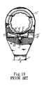
- FIGS. 18 and 19illustrate another conventional wrench comprising a handle 1 ′′ and a head 11 ′′ extended from the handle 1 ′′.
- a hole 14 ′′is defined in the head 11 ′′ for rotatably receiving a drive member 2 ′′.
- a transverse hole 12 ′′ having an open endis defined in a web between the handle 1 ′′ and the head 11 ′′.
- a spring 4 ′′ and a ball 5 ′′are received in a receptacle defined in a peripheral wall defining the transverse hole 12 ′′.
- a pawl 3 ′′ having two toothed sections 31 ′′is slidably mounted in the transverse hole 12 ′′ and then sealed by a cap 9 ′′.
- a substantially T-shaped switching member 8 ′′includes a horizontal section 81 ′′ outside the head 11 ′′ for manual operation and a threaded vertical section 82 ′′ extending through a slot 13 ′′ in the web into a screw hole 33 ′′ in the pawl 3 ′′.
- the ball 5 ′′is biased by the spring 4 ′′ to engage with one of two retaining grooves 32 ′′ of the pawl 3 ′′ such that one of the toothed sections 31 ′′ of the pawl 3 ′′ is engaged with the teeth of the drive member 2 ′′, thereby deciding the ratcheting direction of the wrench.
- the cap 9 ′′is apt to be disengaged from the transverse hole 12 ′′.
- the movement of the pawl 3 ′′is limited if the cap 9 ′′ is mounted in a deeper position for avoiding disengagement.
- the threaded vertical section 82 ′′ of the switching member 8 ′′ and the screw hole 33 ′′ of the pawl 3 ′′result in difficulty in manufacture and assembly.
- the threaded vertical section 82 ′′ of the switching member 8 ′′tends to be disengaged from the screw hole 33 ′′ of the pawl 3 ′′ after a period of time, and the wrench malfunctions accordingly.
- a wrench in accordance with the present inventioncomprises:
- a headextending from the handle and including a hole
- a webdefined between the handle and the head, the web including a side and a compartment communicated with the hole of the head, an opening being defined in the side of the web and communicated with the compartment;
- a drive memberrotatably mounted in the hole of the head and including a plurality of teeth in an outer periphery thereof;
- a pawlslidably received in the compartment and including a first side having a plurality of teeth and a second side opposite to the first side, the pawl further including a recessed portion;
- a switching memberhaving a first end for manual operation and a second end extending through the opening of the web into the recessed portion of the pawl;
- an elastic elementmounted in the compartment for urging the pressing member to press against the second side of the pawl for engaging the teeth of the pawl with the teeth of the drive member;
- the first end of the switching memberis manually slidable to move the pawl between a first position and a second position corresponding to two opposite ratcheting directions of the wrench;
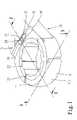
- FIG. 1is a perspective view of a ratchet-type reversible wrench in accordance with the present invention.
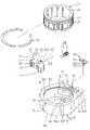
- FIG. 2is an exploded perspective view of the wrench in FIG. 1 .
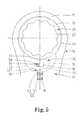
- FIG. 3is a sectional view taken along plane 3 — 3 in FIG. 1 .
- FIG. 4is a sectional view taken along plane 4 — 4 in FIG. 3 .
- FIG. 5is a sectional view taken along plane 5 — 5 in FIG. 1 .
- FIG. 6is a view similar to FIG. 5 , illustrating free rotation of the wrench handle.
- FIG. 7is a view similar to FIG. 4 , illustrating change in the ratcheting direction by moving a switching member.
- FIG. 8is a sectional view similar to FIG. 5 , illustrating a transition position of the pawl of the wrench during switching of the ratcheting direction.
- FIG. 9is a sectional view similar to FIG. 5 , illustrating a final position of the pawl of the wrench after switching of the ratcheting direction.
- FIG. 10is a sectional view similar to FIG. 4 , illustrating a final position of the switching member of the wrench after switching of the ratcheting direction.
- FIG. 11is a perspective view of a modified embodiment of the ratchet-type reversible wrench in accordance with the present invention.
- FIG. 12is an exploded perspective view of the ratchet-type reversible wrench in FIG. 11 .
- FIG. 13is a perspective view of another modified embodiment of the ratchet-type reversible wrench in accordance with the present invention.
- FIG. 14is a perspective view of a further modified embodiment of the ratchet type reversible wrench in accordance with the present invention.
- FIG. 15is an exploded perspective view of the ratchet-type reversible wrench in FIG. 14 .
- FIG. 16is an exploded perspective view of a conventional wrench.
- FIG. 17is a sectional view of the wrench in FIG. 16 .
- FIG. 18is an exploded perspective view of another conventional wrench.
- FIG. 19is a sectional view of the wrench in FIG. 18 .
- a reversible ratchet-type wrench in accordance with the present inventionis designated by “ 10 ” and generally comprises a handle 12 and a head 11 extending from the handle 12 .
- a web 14is defined between the handle 12 and the head 11 .
- a hole 13is defined in the head 11 and extends from a top face 111 to a bottom face 112 of the head 11 .
- a compartment 15is defined in the web 14 and communicated with the hole 13 of the head 11 .
- the compartment 15is delimited by an upper wall 151 , a bottom wall 152 , and a peripheral wall 153 .
- a receptacle 18is defined in the peripheral wall 153 of the compartment 15 and faces the hole 13 .
- An opening (or slot or hole) 16is defined in a side of the web 14 (i.e., the upper wall 151 of the compartment 15 ) and communicated with the compartment 15 .
- a transverse channel 19is defined in the side of the web 14 and extends from a lateral side of the web 14 through the other lateral side of the web 14 .
- the opening 16is defined in a bottom wall defining the transverse channel 19 , leaving a bridge 17 between the web 14 and the head 11 . It is noted that the head 11 is still integral with the handle 12 via the bridge 17 and the bottom wall defining the transverse channel 19 , providing a strong structure.
- An annular groove 132is defined in an end of a peripheral wall 131 defining the hole 13 of the head 11 .
- a drive member 20is rotatably mounted in the hole 13 of the head 11 .
- the drive member 20is a gear wheel including a plurality of teeth 21 in an outer periphery thereof.
- the outer periphery of the gear wheel 20includes an annular groove 23 in an upper end thereof.
- the gear wheel 20includes an inner periphery 22 for driving a fastener (not shown).
- a C-clip 24is partially engaged in the annular groove 23 of the gear wheel 20 and partially engaged in the annular groove 132 of the head 11 , thereby rotatably mounting the gear wheel 20 in the hole 13 .
- a pawl 30is slidably mounted in the compartment 15 and includes a first lateral side having a plurality of teeth 31 and a second lateral side opposite to the first lateral side.
- a retaining section 32is formed on the second lateral side of the pawl 30 .
- the retaining section 32includes two retaining grooves 320 spaced by a ridge 322 , each retaining groove 320 including a retaining portion 321 .
- the pawl 30further includes two pressing ends 33 and 35 for pressing against the peripheral wall 153 defining the compartment 15 . Further, the pawl 30 includes a recessed portion 38 in a top side 37 thereof.
- a biasing means 40comprised of an elastic element 41 and a pressing member (e.g., a ball 42 ).
- the ball 42is biased by the elastic element 41 to be selectively engaged in one of the retaining grooves 320 of the pawl 30 , thereby selectively urging one of the pressing ends 33 and 35 of the pawl 30 to press against the peripheral wall 153 defining the compartment 15 and urging the teeth 31 of the pawl 30 to engage with the teeth 22 of the gear wheel 20 .
- the reversible ratchet wrenchfurther includes a switching member 50 that is preferably T-shaped and has a first end 51 and a second end 52 with an engaging groove 53 .
- the first end 51 of the switching member 50is slidably received in the channel 19 .
- the second end 52 of the switching member 50extends through the opening 16 of the web 14 into the recessed portion 38 of the pawl 30 .
- a resilient retaining plate 56includes two curved sides 561 and an intermediate notched portion 562 between the curved sides 561 . As illustrated in FIGS.
- the resilient retaining plate 56is engaged with the engaging groove 53 of the second end 52 of the switching member 50 at the intermediate notched portion 562 , with the curved sides 561 of the resilient retaining plate 56 pressing against the upper wall 151 defining the compartment 15 .
- the switching member 50is retained in place unless a relatively large force is applied to the switching member 50 for moving the pawl 30 for switching the ratcheting direction of the wrench 10 .
- the switching member 50When the switching member 50 is in a position shown in FIG. 5 , the second end 52 of the switching member 50 is located in a left end of the opening 16 of the web 14 and in a right portion of the recessed portion 38 of the pawl 30 .
- the pressing end 33presses against a portion of the peripheral wall 153 defining the compartment 15 , allowing clockwise ratcheting operation and counterclockwise free rotation of the wrench 10 .
- FIG. 6illustrates movement of the pawl 30 during free rotation of the wrench 10 .
- the pawl 30slides away from the gear wheel 20 and compresses the elastic element 41 and then reengages with the gear wheel 20 under the action of the elastic element 41 and the ball 42 .
- the procedurerepeats and thus causes free rotation of the wrench 10 ; namely, the fastener (not shown) in the gear wheel 20 is not turned, as the gear wheel 20 is not driven by the pawl 30 .
- the recessed portion 38 of the pawl 30is wider than the second end 52 of the switching member 50 and since the second end 52 of the switching member 50 is located in the right portion of the recessed portion 38 , the second end 52 of the switching member 50 is not moved when the pawl 30 moves during free rotation of the wrench 10 .
- the first end 51 of the switching member 50is moved along the channel 19 until the ball 42 is moved to the ridge 322 and the second end 52 of the switching member 50 reaches the right end edge of the recessed portion 38 of the pawl 30 .
- the first end 51 of the switching member 50is further moved until the ball 42 moves across the ridge 322 into the other retaining groove 320 .
- the pawl 30is moved across the central line of the compartment 15 to the other side of the compartment 15 , as shown in FIGS. 9 and 10 .
- the switching member 50When the switching member 50 is in a position shown in FIGS. 9 and 10 , the second end 52 of the switching member 50 is located in a right end of the opening 16 of the web 14 and in a left portion of the recessed portion 38 of the pawl 30 .
- the pressing end 35 of the pawl 30presses against another portion of the peripheral wall 153 defining the compartment 15 , allowing counterclockwise ratcheting operation and clockwise free rotation of the wrench 10 .
- the pawl 30slides away from the gear wheel 20 and compresses the elastic element 41 and then reengages with the gear wheel 20 under the action of the elastic element 41 and the ball 42 .
- the procedurerepeats and thus causes free rotation of the wrench 10 ; namely, the fastener (not shown) in the gear wheel 20 is not turned, as the gear wheel 20 is not driven by the pawl 30 . Since the recessed portion 38 of the pawl 30 is wider than the second end 52 of the switching member 50 and since the second end 52 of the switching member 50 is located in the left portion of the recessed portion 38 , the second end 52 of the switching member 50 is not moved when the pawl 30 moves during free rotation of the wrench 10 .
- the first end 51 of the switching member 50is flush with an upper end of the channel 19 , allowing smooth operation.
- FIGS. 11 and 12illustrate a modified embodiment of the invention, wherein the only difference between this embodiment and the above embodiment is that the channel 19 in the above embodiment is omitted. It is noted that two lateral sides of the second end 52 of the switching member 50 are respectively guided and limited by two lateral walls defining the opening 16 . Thus, undesired rotation of the switching member 50 is prevented.
- FIG. 13illustrates another modified embodiment of the invention, wherein the channel 19 is omitted.
- the drive member(now designated by 20 ′) includes a solid gear wheel (not shown) having teeth formed on an outer periphery and a drive column 21 ′ extending downward from a bottom side of the gear wheel for releasably engaging with a socket (not shown). Structure of the head 11 of the wrench 10 is not sacrificed due to provision of the bridge 17 .
- FIGS. 14 and 15show a further modified embodiment of the invention, wherein the channel 19 is defined in a side of the web 14 and spaced from two lateral sides of the web 14 .
- the opening 16 defined in a bottom wall defining the transverse channel 19is substantially circular, and the second end 52 of the switching member 50 is cylindrical and extends through the opening 16 .
- the opening 16allows transverse movement of the switching member 50 relative to the handle 12 .
- the second end 52 of the switching member 50includes two lateral sides that are respectively guided and limited by two lateral walls defining the transverse channel 19 . Thus, undesired rotation of the switching member 50 is prevented.
- the switching member 50is reliably retained in place during ratcheting operation and free rotation of the wrench 10 .
- Structure of the head 11 of the wrench 10is not sacrificed due to provision of the bridge 17 .
- the pawl 30is allowed to slide away from the drive member 20 without causing movement of the switching member 50 during free rotation of the wrench 10 .
Landscapes
- Engineering & Computer Science (AREA)
- Mechanical Engineering (AREA)
- Details Of Spanners, Wrenches, And Screw Drivers And Accessories (AREA)
Abstract
Description
1. Field of the Invention
The present invention relates to a reversible ratchet-type wrench. In particular, the present invention relates to a ratchet-type wrench that allows reversible operations without the risk of movement of a switching member for switching the ratcheting direction.
2. Description of the Related Art
Wrenches are an important hand tool and have many types such as spanners, adjusting wrenches, combination wrenches, and socket wrenches. Ring spanners are very useful when the fastener to be tightened/loosened is located in a difficult-to-access place. However, the ring spanners could not be operated in a reverse direction and thus require troublesome disengagement of the ring spanner from the fastener and reengagement of the ring spanner until tightening/loosening of the fastener is achieved.
U.S. Pat. No. 6,220,123 to Chen issued on Apr. 24, 2001 discloses a structure of a ratchet wrench comprising a ratchet wheel mounted in a circular opening of a wrench head of a common ratchet, and a cavity is provided in the circular opening adjacent to one side of the rod body of the wrench for mounting a restrictive teeth structure. The end terminal of the cavity is provided with a ball hole to contain a spring and a steel ball, and the restrictive teeth structure is urged by the steel ball to thereby control the high-torque movement of the ratchet wheel. A rotating disc is used to cover the opening and includes ratchet teeth for meshing top ratchet teeth of the restrictive teeth structure. However, the formation of top and bottom ratchet teeth on a side of the restrictive teeth structure would not be easy, and this decreases the torque-bearing capacity of the ratchet wrench, as the meshing area between the restrictive teeth structure and the ratchet wheel is reduced. Further, the restrictive teeth structure could not be reliably positioned, as there is no positioning means provided between the rotating disc and the wrench body. As a result, the rotating disc moves together with the restrictive teeth structure when the ratchet wrench turns freely. Further, since the top ratchet teeth of the restrictive teeth structure meshes with the ratchet teeth of the rotating disc and the bottom ratchet teeth of the rotating disc meshes with the ratchet teeth of the ratchet wheel, the ratchet wrench must be disengaged from the fastener before switching of the ratcheting direction through rotation of the rotating disc. Further, the engaging force between the ratchet wheel and the rotating disc provided by a C-shaped fastening ring was found to be poor. As a result, the ratchet wheel and the rotating disc could fly away from the wrench body when the ratchet wrench is subject to a relatively high torque.
It is, therefore, an objective of the present invention to provide a ratchet-type wrench that allows reversible operations without the risk of movement of a switching member for switching the ratcheting direction.
A wrench in accordance with the present invention comprises:
a handle;
a head extending from the handle and including a hole;
a web defined between the handle and the head, the web including a side and a compartment communicated with the hole of the head, an opening being defined in the side of the web and communicated with the compartment;
a drive member rotatably mounted in the hole of the head and including a plurality of teeth in an outer periphery thereof;
a pawl slidably received in the compartment and including a first side having a plurality of teeth and a second side opposite to the first side, the pawl further including a recessed portion;
a switching member having a first end for manual operation and a second end extending through the opening of the web into the recessed portion of the pawl;
a pressing member mounted in the compartment; and
an elastic element mounted in the compartment for urging the pressing member to press against the second side of the pawl for engaging the teeth of the pawl with the teeth of the drive member;
wherein the first end of the switching member is manually slidable to move the pawl between a first position and a second position corresponding to two opposite ratcheting directions of the wrench; and
wherein the recessed portion of the pawl and the second end of the switching member are so configured that the switching member is not moved when the pawl moves as a result of free rotation of the wrench.
Other objectives and novel features of the invention will become more apparent from the following detailed description when taken in conjunction with the accompanying drawings.
Referring toFIGS. 1 through 3 , a reversible ratchet-type wrench in accordance with the present invention is designated by “10” and generally comprises ahandle 12 and ahead 11 extending from thehandle 12. Aweb 14 is defined between thehandle 12 and thehead 11. Ahole 13 is defined in thehead 11 and extends from atop face 111 to abottom face 112 of thehead 11. Acompartment 15 is defined in theweb 14 and communicated with thehole 13 of thehead 11. As illustrated inFIGS. 2 and 3 , thecompartment 15 is delimited by anupper wall 151, abottom wall 152, and aperipheral wall 153. Areceptacle 18 is defined in theperipheral wall 153 of thecompartment 15 and faces thehole 13.
An opening (or slot or hole)16 is defined in a side of the web14 (i.e., theupper wall 151 of the compartment15) and communicated with thecompartment 15. In this embodiment, atransverse channel 19 is defined in the side of theweb 14 and extends from a lateral side of theweb 14 through the other lateral side of theweb 14. Theopening 16 is defined in a bottom wall defining thetransverse channel 19, leaving abridge 17 between theweb 14 and thehead 11. It is noted that thehead 11 is still integral with thehandle 12 via thebridge 17 and the bottom wall defining thetransverse channel 19, providing a strong structure. Anannular groove 132 is defined in an end of aperipheral wall 131 defining thehole 13 of thehead 11.
Adrive member 20 is rotatably mounted in thehole 13 of thehead 11. In this embodiment, thedrive member 20 is a gear wheel including a plurality ofteeth 21 in an outer periphery thereof. The outer periphery of thegear wheel 20 includes anannular groove 23 in an upper end thereof. Further, thegear wheel 20 includes aninner periphery 22 for driving a fastener (not shown). A C-clip 24 is partially engaged in theannular groove 23 of thegear wheel 20 and partially engaged in theannular groove 132 of thehead 11, thereby rotatably mounting thegear wheel 20 in thehole 13.
Apawl 30 is slidably mounted in thecompartment 15 and includes a first lateral side having a plurality ofteeth 31 and a second lateral side opposite to the first lateral side. A retainingsection 32 is formed on the second lateral side of thepawl 30. In this embodiment, the retainingsection 32 includes two retaininggrooves 320 spaced by aridge 322, each retaininggroove 320 including a retainingportion 321. Thepawl 30 further includes twopressing ends peripheral wall 153 defining thecompartment 15. Further, thepawl 30 includes a recessedportion 38 in atop side 37 thereof.
Mounted in thereceptacle 18 is a biasing means40 comprised of anelastic element 41 and a pressing member (e.g., a ball42). Theball 42 is biased by theelastic element 41 to be selectively engaged in one of the retaininggrooves 320 of thepawl 30, thereby selectively urging one of the pressing ends33 and35 of thepawl 30 to press against theperipheral wall 153 defining thecompartment 15 and urging theteeth 31 of thepawl 30 to engage with theteeth 22 of thegear wheel 20.
Still referring toFIGS. 1–3 , the reversible ratchet wrench further includes a switchingmember 50 that is preferably T-shaped and has afirst end 51 and asecond end 52 with an engaginggroove 53. Thefirst end 51 of the switchingmember 50 is slidably received in thechannel 19. Thesecond end 52 of the switchingmember 50 extends through theopening 16 of theweb 14 into the recessedportion 38 of thepawl 30. Aresilient retaining plate 56 includes twocurved sides 561 and an intermediate notchedportion 562 between thecurved sides 561. As illustrated inFIGS. 3 and 4 , the resilient retainingplate 56 is engaged with the engaginggroove 53 of thesecond end 52 of the switchingmember 50 at the intermediate notchedportion 562, with thecurved sides 561 of the resilient retainingplate 56 pressing against theupper wall 151 defining thecompartment 15. Thus, the switchingmember 50 is retained in place unless a relatively large force is applied to the switchingmember 50 for moving thepawl 30 for switching the ratcheting direction of thewrench 10.
When the switchingmember 50 is in a position shown inFIG. 5 , thesecond end 52 of the switchingmember 50 is located in a left end of theopening 16 of theweb 14 and in a right portion of the recessedportion 38 of thepawl 30. Thepressing end 33 presses against a portion of theperipheral wall 153 defining thecompartment 15, allowing clockwise ratcheting operation and counterclockwise free rotation of thewrench 10.
Referring toFIGS. 7 and 8 , when switching of the ratcheting direction of the wrench is required, thefirst end 51 of the switchingmember 50 is moved along thechannel 19 until theball 42 is moved to theridge 322 and thesecond end 52 of the switchingmember 50 reaches the right end edge of the recessedportion 38 of thepawl 30. Thefirst end 51 of the switchingmember 50 is further moved until theball 42 moves across theridge 322 into the other retaininggroove 320. Thepawl 30 is moved across the central line of thecompartment 15 to the other side of thecompartment 15, as shown inFIGS. 9 and 10 .
When the switchingmember 50 is in a position shown inFIGS. 9 and 10 , thesecond end 52 of the switchingmember 50 is located in a right end of theopening 16 of theweb 14 and in a left portion of the recessedportion 38 of thepawl 30. Thepressing end 35 of thepawl 30 presses against another portion of theperipheral wall 153 defining thecompartment 15, allowing counterclockwise ratcheting operation and clockwise free rotation of thewrench 10.
When the wrench is turned clockwise, thepawl 30 slides away from thegear wheel 20 and compresses theelastic element 41 and then reengages with thegear wheel 20 under the action of theelastic element 41 and theball 42. The procedure repeats and thus causes free rotation of thewrench 10; namely, the fastener (not shown) in thegear wheel 20 is not turned, as thegear wheel 20 is not driven by thepawl 30. Since the recessedportion 38 of thepawl 30 is wider than thesecond end 52 of the switchingmember 50 and since thesecond end 52 of the switchingmember 50 is located in the left portion of the recessedportion 38, thesecond end 52 of the switchingmember 50 is not moved when thepawl 30 moves during free rotation of thewrench 10.
Thefirst end 51 of the switchingmember 50 is flush with an upper end of thechannel 19, allowing smooth operation.
According to the above description, it is appreciated that the switchingmember 50 is reliably retained in place during ratcheting operation and free rotation of thewrench 10. Structure of thehead 11 of thewrench 10 is not sacrificed due to provision of thebridge 17. Further, thepawl 30 is allowed to slide away from thedrive member 20 without causing movement of the switchingmember 50 during free rotation of thewrench 10.
Although the invention has been explained in relation to its preferred embodiments, it is to be understood that many other possible modifications and variations can be made without departing from the scope of the invention as hereinafter claimed.
Claims (20)
1. A wrench comprising:
a handle;
a head extending from the handle and including a hole;
a web defined between the handle and the head, the web including a side and a compartment communicated with the hole of the head, an opening being defined in the side of the web and communicated with the compartment;
a drive member rotatably mounted in the hole of the head and including a plurality of teeth in an outer periphery thereof;
a pawl slidably received in the compartment and including a first side having a plurality of teeth and a second side opposite to the first side, the pawl further including a recessed portion; and
a switching member having a first end for manual operation and a second end extending through the opening of the web into the recessed portion of the pawl, with the first end being of a size larger than the second end and unable to extend through the opening of the web;
wherein the switching member is manually slidable in a sliding direction between a first position and a second position corresponding to two opposite ratcheting directions of the wrench; and
wherein the recessed portion of the pawl and the second end of the switching member each has a lateral width parallel to the sliding direction of the switch member between the first and second positions, with the lateral width of the recessed portion being wider than the lateral width of the second end of the switching member, with the second end of the switching member being slideable in the sliding direction relative to the recessed portion, with the pawl slideable in the sliding direction relative to the switch member between an engaged position and a disengaged position, with the pawl in the engaged position being pressed toward the drive member to engage teeth of the plurality of teeth of the pawl with teeth of the plurality of teeth of the drive member for ratcheting operation of the drive member when the drive member is rotated in a corresponding one of the two opposite ratcheting directions, with the pawl in the disengaged position facilitating free rotation operation of the drive member such that the switching member is not moved when the pawl moves as a result of free rotation of the drive member, with the opening being defined by spaced, parallel, lateral walls extending parallel to the sliding direction, with the second end of the switching member including spaced, parallel, lateral sides extending parallel to the sliding direction.
2. The wrench as claimed inclaim 1 , wherein the web includes a transverse channel defined in the side thereof, the opening of the web being defined in a bottom wall defining the transverse channel.
3. The wrench as claimed inclaim 2 , wherein the first end of the switching member has a top that is flush with the side of the web.
4. The wrench as claimed inclaim 2 , wherein the web includes two opposed lateral sides, with the transverse channel extending from one of the two opposed lateral sides through the other of the two opposed lateral sides.
5. The wrench as claimed inclaim 1 , wherein the switching member is substantially T-shaped.
6. A wrench comprising:
a handle;
a head extending from the handle and including a hole;
a web defined between the handle and the head, with the web including a side and a compartment communicated with the hole of the head, with an opening being defined in the side of the web and communicated with the compartment;
a drive member rotatably mounted in the hole of the head and including a plurality of teeth in an outer periphery thereof;
a pawl slidably received in the compartment and including a first side having a plurality of teeth and a second side opposite to the first side, with the pawl further including a recessed portion;
a switching member having a first end for manual operation and a second end extending through the opening of the web into the recessed portion of the pawl, wherein the second end of the switching member includes an engaging groove; and
a resilient retaining plate engaged with the engaging groove, with the resilient retaining plate including at least one curved portion pressing against a wall portion defining the compartment of the web, thereby retaining the switching member in place;
wherein the first end of the switching member is manually slidable to move the pawl between a first position and a second position corresponding to two opposite ratcheting directions of the wrench; and
wherein the recessed portion of the pawl and the second end of the switching member are so configured that the switching member is not moved when the pawl moves as a result of free rotation of the wrench.
7. The wrench as claimed inclaim 6 wherein the second end of the switching member is a rod having the engaging groove, with the engaging groove being annular, with the recessed portion of the pawl being wider than the rod, with the at least one curved portion including two curved sides pressing against the wall portion defining the compartment of the web, thereby retaining the switching member in place, with the resilient retaining plate further including an intermediate notched portion formed between the curved sides and engaged with the annular engaging groove.
8. The wrench as claimed inclaim 1 , wherein a cavity is defined in a wall defining the compartment, with the second side of the pawl being pressed toward the drive member for engaging the pawl with the drive member by a pressing member biased by an elastic element, with the elastic element and the pressing member being mounted in the cavity in the compartment.
9. The wrench as claimed inclaim 8 , wherein the second side of the pawl includes two retaining grooves spaced by a ridge.
10. The wrench as claimed inclaim 1 , wherein the pawl includes two pressing ends for selectively pressing a peripheral wall defining the compartment.
11. The wrench as claimed inclaim 1 , wherein the drive member is a gear wheel having an inner periphery.
12. The wrench as claimed inclaim 1 , wherein the drive member includes a gear wheel and a drive column for engaging with a socket.
13. The wrench as claimed inclaim 1 , wherein a bridge is delimited between the opening of the web and the hole of the head.
14. The wrench as claimed inclaim 2 , wherein the first end of the switching member includes two lateral sides that are respectively guided and limited by two lateral walls defining the transverse channel, thereby preventing rotation of the switching member.
15. A wrench comprising:
a handle;
a head extending from the handle and including a hole;
a web defined between the handle and the head, with the web including a side and a compartment communicated with the hole of the head, with an opening being defined in the side of the web and communicated with the compartment;
a drive member rotatably mounted in the hole of the head and including a plurality of teeth in an outer periphery thereof;
a pawl slidably received in the compartment and including a first side having a plurality of teeth and a second side opposite to the first side, with the pawl further including a recessed portion; and
a switching member having a first end for manual operation and a second end extending through the opening of the web into the recessed portion of the pawl, with the first end being of a size larger than the second end and unable to extend through the opening of the web, wherein the second end of the switching member includes two, spaced, parallel lateral sides that are respectively guided and limited by two, spaced, parallel lateral walls defining the opening, thereby preventing rotation of the switching member and the first end of the switching member;
wherein the first end of the switching member is manually slidable to move the pawl between a first position and a second position corresponding to two opposite ratcheting directions of the wrench; and
wherein the recessed portion of the pawl and the second end of the switching member are so configured that the switching member is not moved when the pawl moves as a result of free rotation of the wrench.
16. The wrench as claimed inclaim 1 , with the recessed portion of the pawl, the second end of the switching member, and the opening in the web each being rectangular.
17. The wrench as claimed inclaim 6 with the pawl being pressed toward the drive member by a pressing member biased by an elastic element, with the pressing member mounted in the compartment, with the elastic element mounted in the compartment for urging the pressing member to press against the second side of the pawl for engaging the teeth of the pawl with the teeth of the drive member.
18. The wrench as claimed inclaim 1 with the pawl being pressed toward the drive member by a pressing member biased by an elastic element, with the pressing member mounted in the compartment, with the elastic element mounted in the compartment for urging the pressing member to press against the second side of the pawl for engaging the teeth of the pawl with the teeth of the drive member.
19. The wrench as claimed inclaim 15 with the pawl being pressed toward the drive member by a pressing member biased by an elastic element, with the pressing member mounted in the compartment, with the elastic element mounted in the compartment for urging the pressing member to press against the second side of the pawl for engaging the teeth of the pawl with the teeth of the drive member.
20. The wrench as claimed inclaim 15 with the pawl further comprising two pressing ends for selectively pressing a peripheral wall defining the compartment, with the second side of the pawl including two retaining grooves spaced by a ridge, with the pawl being pressed toward the drive member by a pressing member biased by an elastic element, with one of the two retaining grooves on the second side of the pawl guiding the pressing member to press a corresponding one of the two pressing ends against the peripheral wall defining the compartment to enhance engagement of the teeth of the pawl and the teeth of the drive member when the drive member is rotated in the corresponding one of the two opposite ratcheting directions.
Priority Applications (1)
| Application Number | Priority Date | Filing Date | Title |
|---|---|---|---|
| DE2003122161DE10322161B4 (en) | 2002-09-03 | 2003-05-16 | Reversible ratchet wrench |
Applications Claiming Priority (3)
| Application Number | Priority Date | Filing Date | Title |
|---|---|---|---|
| TW090217709UTW503802U (en) | 2001-10-17 | 2001-10-17 | Invertible ratchet wrench |
| TW90217709 | 2001-10-17 | ||
| TW90217709U | 2001-10-17 |
Publications (2)
| Publication Number | Publication Date |
|---|---|
| US20030070512A1 US20030070512A1 (en) | 2003-04-17 |
| US7017453B2true US7017453B2 (en) | 2006-03-28 |
Family
ID=21686920
Family Applications (1)
| Application Number | Title | Priority Date | Filing Date |
|---|---|---|---|
| US10/233,732Expired - LifetimeUS7017453B2 (en) | 2001-10-17 | 2002-09-03 | Reversible ratchet-type wrench |
Country Status (2)
| Country | Link |
|---|---|
| US (1) | US7017453B2 (en) |
| TW (1) | TW503802U (en) |
Cited By (13)
| Publication number | Priority date | Publication date | Assignee | Title |
|---|---|---|---|---|
| US7162937B1 (en)* | 2006-07-19 | 2007-01-16 | Heng-Jian Weng | Positioning device for a two-way ratchet tool |
| US20080085151A1 (en)* | 2006-10-04 | 2008-04-10 | Pazdirek Jiri V | Light weight ball joint |
| US20080223180A1 (en)* | 2007-03-14 | 2008-09-18 | Ping-Chung Huang | Ratchet mechanism for ratchet tool |
| US20100275737A1 (en)* | 2009-05-01 | 2010-11-04 | Lin Chien-Yueh | Bi-directional ratchet wrench |
| USD660109S1 (en)* | 2011-11-30 | 2012-05-22 | Chih-Min Chang | Ratchet wrench |
| USD660666S1 (en)* | 2011-11-30 | 2012-05-29 | Chih-Min Chang | Ratchet wrench |
| US20140020519A1 (en)* | 2012-07-23 | 2014-01-23 | Chih-Min Chang | Ratchet wrench |
| US8820195B2 (en) | 2010-07-01 | 2014-09-02 | Stanley Black & Decker, Inc. | Bit or fastener driver |
| US20150075332A1 (en)* | 2013-09-13 | 2015-03-19 | Chia-Yu Chen | Pass-thru ratchet wrench |
| US20150239104A1 (en)* | 2014-02-25 | 2015-08-27 | Yi-Fu Chen | Ratchet wrench |
| US20150328750A1 (en)* | 2014-05-15 | 2015-11-19 | Snap-On Incorporated | Ratchet mechanism for ratchet wrench |
| US9248556B1 (en)* | 2014-07-08 | 2016-02-02 | Zhi-Ji Chen | Positioning device for ratchet wrench |
| RU205898U1 (en)* | 2021-04-21 | 2021-08-11 | Федеральное государственное автономное образовательное учреждение высшего образования «Южно-Уральский государственный университет (национальный исследовательский университет)» | Universal hand tools |
Families Citing this family (23)
| Publication number | Priority date | Publication date | Assignee | Title |
|---|---|---|---|---|
| US6148695A (en) | 1999-08-03 | 2000-11-21 | Hu; Bobby | Ratchet wheel with asymmetric arcuate concave teeth or non-arcuate concave teeth and ratcheting tools with such ratchet wheel |
| TW408653U (en)* | 2000-02-03 | 2000-10-11 | Hu Hou Fei | Ratcheting tool |
| JP3515763B2 (en) | 2000-03-13 | 2004-04-05 | 厚飛 胡 | Reversible ratchet tool with small head and improved drive torque |
| US6701768B2 (en)* | 2000-06-22 | 2004-03-09 | Hand Tool Design Corporation | Process for making ratchet wheels |
| TW503802U (en) | 2001-10-17 | 2002-09-21 | Hou-Fei Hu | Invertible ratchet wrench |
| US6945141B2 (en) | 2002-04-22 | 2005-09-20 | Bobby Hu | Reversible ratchet type wrench |
| TW567123B (en)* | 2002-07-22 | 2003-12-21 | Hou-Fei Hu | Ratchet wrench capable of fast rotation |
| TWI245684B (en)* | 2002-08-05 | 2005-12-21 | Yan-Wen Lin | Simple ratchet wrench |
| US6868759B2 (en)* | 2002-08-20 | 2005-03-22 | Easco Hand Tools Inc. | Reversible ratcheting tool |
| US20040074343A1 (en)* | 2002-10-18 | 2004-04-22 | Chih-Ching Hsieh | Ratchet wrench |
| US20050044997A1 (en)* | 2003-08-25 | 2005-03-03 | Liu Ling Lang | High torsional force structure for a ratchet device |
| US6988429B2 (en) | 2004-01-06 | 2006-01-24 | Easco Hand Tools, Inc. | Reversible ratcheting tool with improved control member |
| US20060065078A1 (en)* | 2004-09-28 | 2006-03-30 | Shih-Kun Chen | Ratchet tool with easily removable C-shaped clip |
| US7062994B2 (en)* | 2004-10-14 | 2006-06-20 | Ching Chen | Ratchet wrench |
| USD550528S1 (en)* | 2006-03-14 | 2007-09-11 | Chih-Ching Hsieh | Switch of a ratchet spanner |
| USD554453S1 (en)* | 2006-06-27 | 2007-11-06 | Chih-Ching Hsieh | Switch of ratchet wheel |
| TW201004745A (en)* | 2008-07-24 | 2010-02-01 | Hou-Fei Hu | Slipping type direction-change ratchet wrench |
| US20100242685A1 (en)* | 2009-03-31 | 2010-09-30 | Chih-Min Chang | Ratchet wrench capable of preventing disengagement of nut |
| JP5957371B2 (en)* | 2012-11-12 | 2016-07-27 | 株式会社プロス | Double-ended ratchet wrench |
| CN103934776B (en)* | 2013-01-18 | 2018-01-09 | 杭州巨星工具有限公司 | Two-way spanner |
| US9643298B2 (en) | 2013-01-18 | 2017-05-09 | Hangzhou Great Star Tools Co., Ltd | Thin bi-directional ratchet wrench |
| US8973476B2 (en)* | 2013-03-13 | 2015-03-10 | Ryeson Corporation | Ratcheting torque wrench |
| USD1012643S1 (en) | 2021-12-21 | 2024-01-30 | Matco Tools Corporation | Ratchet pawl |
Citations (202)
| Publication number | Priority date | Publication date | Assignee | Title |
|---|---|---|---|---|
| US15482A (en) | 1856-08-05 | Wrench | ||
| US726012A (en) | 1903-01-20 | 1903-04-21 | Howard Emmet Andrew | Nut-wrench. |
| US810599A (en) | 1905-04-10 | 1906-01-23 | Eugene K Ansorge | Wrench. |
| US818761A (en) | 1906-01-20 | 1906-04-24 | Frederick A Hanes | Ratchet-wrench. |
| US841686A (en) | 1906-11-20 | 1907-01-22 | John N Hatfield | Wrench. |
| US878657A (en) | 1906-01-02 | 1908-02-11 | Arthur Munch | Ratchet-wrench. |
| US893097A (en) | 1907-09-27 | 1908-07-14 | Joseph M Reams | Reversible ratchet-wrench. |
| US915446A (en) | 1908-09-23 | 1909-03-16 | Joseph M Kearnes | Wrench. |
| US1033358A (en) | 1911-12-09 | 1912-07-23 | John L Turner | Wrench. |
| US1078059A (en) | 1913-10-01 | 1913-11-11 | Frank Mossberg Company | Wrench. |
| US1090578A (en) | 1911-06-10 | 1914-03-17 | Joseph B Smythe | Ratchet mechanism. |
| US1194471A (en) | 1916-08-15 | Combihatiob | ||
| US1261092A (en) | 1914-06-18 | 1918-04-02 | Fred R Allen | Wrench. |
| FR498276A (en) | 1919-04-12 | 1920-01-07 | Costantino Roccati | Key for mechanical parts |
| US1382492A (en) | 1920-12-10 | 1921-06-21 | Evans Lafayette | Wrench |
| US1426127A (en) | 1920-04-23 | 1922-08-15 | Frank Mossberg Company | Ratchet wrench |
| US1601767A (en) | 1923-07-20 | 1926-10-05 | Otto R Peterson | Ratchet wrench |
| US1614039A (en) | 1924-02-01 | 1927-01-11 | Husky Wrench Company | Wrench |
| US1639078A (en) | 1925-03-14 | 1927-08-16 | John E Coe | Ratchet wrench |
| US1680515A (en) | 1926-12-21 | 1928-08-14 | Buda Co | Ratchet mechanism for lifting jacks |
| US1772524A (en) | 1927-04-08 | 1930-08-12 | Snap On Wrench Company | Ratchet wrench |
| US1957462A (en) | 1933-01-25 | 1934-05-08 | Williams J H & Co | Ratchet wrench |
| US2193984A (en) | 1937-04-16 | 1940-03-19 | Armstrong Bros Tool Co | Reversible ratchet wrench |
| US2201827A (en) | 1939-04-17 | 1940-05-21 | Otto P Froeschl | Ratchet mechanism |
| US2201705A (en) | 1938-07-19 | 1940-05-21 | Wright Tool And Forge Company | Ratchet wrench |
| US2317461A (en) | 1940-03-22 | 1943-04-27 | Lucian C Jackson | Wrench |
| US2542241A (en) | 1946-10-23 | 1951-02-20 | New Britain Machine Co | Ratchet mechanism |
| US2612807A (en) | 1947-11-17 | 1952-10-07 | Ralph R Hunt | Ratchet wrench spinner |
| US2657604A (en) | 1952-09-11 | 1953-11-03 | Sherman Klove Co | Ratchet wrench |
| DE921198C (en) | 1944-01-04 | 1954-12-09 | Friedrich Wilhelm Thienes | Nut wrench with free wheel ratchet |
| US2701977A (en) | 1953-05-07 | 1955-02-15 | Wright Tool And Forge Company | Reversible ratchet wrench |
| US2735324A (en) | 1956-02-21 | Friction action ratchet wrench | ||
| US2764048A (en) | 1955-02-07 | 1956-09-25 | Leslie V Thompson | Ratchet wrench |
| US2769360A (en) | 1954-09-10 | 1956-11-06 | Cottrell Wayne Woodford | Angular wrench head having upwardly opening socket |
| US2800821A (en) | 1953-10-01 | 1957-07-30 | New Britain Machine Co | Angularly adjustable, reversible ratchet wrench |
| US2803980A (en) | 1955-12-27 | 1957-08-27 | Irwin R Vogel | Reversible ratchet wrench |
| US2891434A (en) | 1958-04-21 | 1959-06-23 | Lozensky Charles Andrew | Ratchet wrench |
| US2957377A (en) | 1957-09-13 | 1960-10-25 | Terence G Hare | Reversible ratchet type wrench |
| US2978081A (en) | 1956-08-13 | 1961-04-04 | Bahco Ab | Devices in ratchet wrenches |
| US3019682A (en) | 1960-04-08 | 1962-02-06 | Terence G Hare | Reversible ratchet type wrench |
| US3044591A (en) | 1959-08-31 | 1962-07-17 | Luther E Kilness | Ratchet mechanism |
| US3233481A (en) | 1963-10-25 | 1966-02-08 | Kelsey Hayes Co | Ratchet wrench |
| US3250157A (en) | 1963-11-06 | 1966-05-10 | Snap On Tools Corp | Magnetic ratchet mechanism for wrenches and the like |
| US3265171A (en) | 1964-06-22 | 1966-08-09 | Luther E Kilness | One way reversible clutch for wrench |
| US3269496A (en) | 1964-06-22 | 1966-08-30 | Luther E Kilness | Reversible one way clutch for wrench |
| US3337014A (en) | 1965-10-20 | 1967-08-22 | John A Sandrick | Ratchet wrench |
| US3342229A (en) | 1965-10-21 | 1967-09-19 | James Igor | Ratchet handle screwdriver |
| US3393587A (en) | 1966-12-15 | 1968-07-23 | Wright Tool And Forge Company | Ratchet wrenches |
| US3393780A (en) | 1967-01-26 | 1968-07-23 | Luther E. Kilness | Reversible ratchet |
| US3436992A (en) | 1967-03-10 | 1969-04-08 | Pendleton Tool Ind Inc | Reversible ratchet wrench with floating pawls |
| US3508455A (en) | 1968-02-16 | 1970-04-28 | John F Miller | Combination tool |
| US3575069A (en) | 1969-07-29 | 1971-04-13 | Kit C White | Ratchet and speed wrench combination |
| US3577816A (en) | 1969-04-10 | 1971-05-04 | Jerry Alexander | Ratchet wrench |
| US3598001A (en) | 1969-02-14 | 1971-08-10 | Lowell Corp | Reversible ratchet handle for socket wrench |
| US3606940A (en) | 1969-01-11 | 1971-09-21 | Walter Finkeldei Werkzeugfabri | Ratchet switchable into opposite directions of operation |
| US3691876A (en) | 1971-02-08 | 1972-09-19 | Leon Cassidy Jr | Ratchet spinner wrench |
| US3713356A (en) | 1971-01-18 | 1973-01-30 | Snap On Tools Corp | Socket release mechanism for wrenches and the like |
| US3742788A (en) | 1972-07-20 | 1973-07-03 | Parker Mfg Co | Ratchet wrench |
| US3783703A (en) | 1972-11-17 | 1974-01-08 | Jo Line Tools | Ratchet mechanism |
| US3838614A (en) | 1972-12-12 | 1974-10-01 | Donnell W O | Reciprocating engine barring tool |
| US3866492A (en) | 1974-03-06 | 1975-02-18 | Jo Line Tools | Torque multiplier |
| US3908487A (en) | 1971-09-10 | 1975-09-30 | Stanley Works | Rotary hand tool |
| US3970155A (en) | 1974-01-14 | 1976-07-20 | Jo-Line Tools, Inc. | Electronic torque wrench |
| US4053037A (en) | 1976-06-10 | 1977-10-11 | Jo-Line Tools, Inc. | Reversing ratchet |
| US4070932A (en) | 1977-03-01 | 1978-01-31 | Jeannotte Richard W | Extensible handle for a tool headpiece |
| US4111077A (en) | 1977-02-02 | 1978-09-05 | Lowell Corporation | Ratchet wrench |
| US4128025A (en) | 1977-08-08 | 1978-12-05 | Main Harvey M | Bolt starting device |
| US4147076A (en) | 1977-10-31 | 1979-04-03 | The Wright Tool And Forge Company | Reversing-ratchet socket wrench |
| GB1559093A (en) | 1977-04-07 | 1980-01-16 | Gordon Tools Ltd | Ratchet drivers |
| US4257507A (en) | 1978-08-15 | 1981-03-24 | Jo-Line Tools, Inc. | Torque wrench with pawl guide |
| US4274311A (en) | 1979-07-23 | 1981-06-23 | Emil Ebert | Ratchet wrench handle |
| US4277989A (en) | 1979-05-01 | 1981-07-14 | Tracy Kurt L | Ratchet wrench handle |
| US4277990A (en) | 1979-11-14 | 1981-07-14 | Duro Metal Products Company | Ratchet wrench |
| US4308768A (en) | 1979-05-10 | 1982-01-05 | Rems-Werk Christian Foll Und Sohne Gmbh & Co. | Ratchet lever |
| US4308769A (en) | 1980-06-02 | 1982-01-05 | Bertha Rantanen | Reversing ratcheting wrench |
| US4328720A (en) | 1980-03-17 | 1982-05-11 | Shiel Walter P | Socket wrench and set |
| US4336728A (en) | 1980-10-08 | 1982-06-29 | Deibert Raymond L | Push-button reversible ratchet and pawl socket wrench handle |
| US4406186A (en) | 1981-05-29 | 1983-09-27 | Gummow Stephen A | Dual action ratchet wrench |
| US4420995A (en) | 1981-06-05 | 1983-12-20 | Roberts Peter M | Quick-release and positive locking mechanism for use on socket wrenches and on power and impact tools |
| GB2135226A (en) | 1983-02-16 | 1984-08-30 | Britool Ltd | Ratchet wrench |
| US4485700A (en) | 1983-01-26 | 1984-12-04 | Colvin David S | Reversible ratchet wrench |
| US4488460A (en) | 1982-07-28 | 1984-12-18 | Easco Corporation | Ergonomic handle for hand tool |
| US4512218A (en) | 1984-03-19 | 1985-04-23 | Chow Kirk K | Control bar for ratchet wrench |
| US4520697A (en) | 1982-09-29 | 1985-06-04 | Moetteli John B | Ratchet wrench |
| US4631988A (en) | 1983-01-26 | 1986-12-30 | Colvin David S | Reversible ratchet wrench including detent mechanism |
| US4662251A (en) | 1985-10-08 | 1987-05-05 | Kohal Lester L | Orthogonal adjustable socket wrench |
| US4709600A (en) | 1984-02-28 | 1987-12-01 | Applied Power, Inc. | Power screw driver with a ratchet wheel having finely graduated toothing |
| US4722252A (en) | 1987-03-02 | 1988-02-02 | Fulcher William A | Power driven wrench |
| US4722253A (en) | 1987-01-21 | 1988-02-02 | Jessie Chow | Reversible ratchet wrench with one-hand accessible switch |
| US4762033A (en) | 1987-02-24 | 1988-08-09 | National Hand Tool Corporation | Ratchet wrench with manual disassembly capability |
| US4770072A (en) | 1985-01-07 | 1988-09-13 | Eduard Wille Gmbh & Co. | Reversible ratchet wrench |
| US4777852A (en) | 1986-10-02 | 1988-10-18 | Snap-On Tools Corporation | Ratcheting screwdriver |
| US4796492A (en) | 1988-05-20 | 1989-01-10 | Liou Mou Tang | Clutch type socket wrench |
| US4807500A (en) | 1986-11-14 | 1989-02-28 | Main Harvey M | Reversing ratchet mechanism for tools |
| US4862775A (en) | 1988-10-19 | 1989-09-05 | Jessie Chow | Control device for ratchet wrenches |
| US4869138A (en) | 1988-02-08 | 1989-09-26 | Farris Jim L | New and improved ratchet tool with rotatable rotor lock and rigid shifter finger |
| US4903554A (en) | 1988-06-02 | 1990-02-27 | Colvin David S | Reversible ratchet wrench with thin head construction |
| US4924737A (en) | 1989-03-20 | 1990-05-15 | Gummow Tool Company | Positive drive ratchet |
| US4934220A (en) | 1989-04-03 | 1990-06-19 | Snap-On Tools Corporation | Sealed reversible ratchet wrench |
| US4986147A (en) | 1989-07-20 | 1991-01-22 | National Hand Tool Corporation | Ratchet wrench having an internally reinforced handle |
| US4991468A (en) | 1990-08-10 | 1991-02-12 | Lee Clark J | Barrel type sockets |
| US5000066A (en) | 1983-07-05 | 1991-03-19 | Gentiluomo Paul A | Ratchet wrench |
| US5012705A (en) | 1990-03-16 | 1991-05-07 | National Hand Tool Corporation | Ratchet wrench with manually removable core |
| US5038452A (en) | 1988-01-28 | 1991-08-13 | Latshaw Enterprises, Inc. | Method of assembling an improved ratcheting tool driver |
| US5076121A (en) | 1989-07-28 | 1991-12-31 | Gregory Fosella | Adjustable ratchet wrench |
| US5095781A (en) | 1991-01-18 | 1992-03-17 | Stanley-Parker, Inc. | Ratchet spinner |
| US5144869A (en) | 1992-03-09 | 1992-09-08 | Jessie Chow | Control device for ratchet wrenches |
| US5157994A (en) | 1991-12-13 | 1992-10-27 | Snap-On Tools Corporation | Ratchet wrench with lost motion reversing mechanism |
| US5178047A (en) | 1991-08-08 | 1993-01-12 | Easco Hand Tools, Inc. | Reversible ratchet wrench |
| US5199335A (en) | 1992-05-11 | 1993-04-06 | Easco Hand Tools, Inc. | Flex-head tool with locking feature |
| US5199330A (en)* | 1991-10-01 | 1993-04-06 | Easco Hand Tools, Inc. | Reversing ratchet wrench |
| US5230262A (en) | 1991-03-27 | 1993-07-27 | Ab Sandvik Bahco | Ratchet wrench |
| US5231903A (en) | 1990-12-20 | 1993-08-03 | Hi-Shear Corporation | Reversible ratchet wrench |
| US5347892A (en) | 1993-03-11 | 1994-09-20 | Moetteli John B | Socket retainer for thin-wall drive member |
| US5404773A (en) | 1992-08-10 | 1995-04-11 | Norville; Burl O. | Cam-action ratchet-type wrench |
| US5448931A (en) | 1989-07-28 | 1995-09-12 | Great Bay Tool Corp. | Adjustable wrench |
| US5522288A (en) | 1994-12-09 | 1996-06-04 | Snap-On Incorporated | Reversible ratchet wrench |
| US5535646A (en) | 1995-02-07 | 1996-07-16 | Stanley Mechanics Tools, Inc. | Ratchet drive |
| US5557994A (en) | 1995-07-17 | 1996-09-24 | Nakayama; Tatsuo | Ratchet handle with torque adjustment |
| US5584220A (en) | 1994-03-01 | 1996-12-17 | Darrah; Scott A. | Angle attachment tool |
| US5595095A (en) | 1994-10-13 | 1997-01-21 | Hillinger; George | Ratcheting socket wrench with intermeshing gears |
| US5622089A (en) | 1995-12-14 | 1997-04-22 | Gifford, Sr.; Robert W. | Ratchet wrench with thumb activated direction control switch |
| US5669875A (en) | 1996-04-16 | 1997-09-23 | United States Surgical Corporation | Endoscopic surgical apparatus with longitudinal actuation |
| US5749272A (en) | 1996-04-24 | 1998-05-12 | Phan; Tan Thanh | Ratchet screw driver |
| US5878635A (en) | 1996-04-16 | 1999-03-09 | Hsieh; Chih-Ching | Reversible ratchet wrench |
| US5884537A (en) | 1997-06-20 | 1999-03-23 | Chen; Chun Chiung | Ratchet tool |
| US5887493A (en) | 1994-07-14 | 1999-03-30 | Main; Harvey M. | Ratchet wrench |
| US5970552A (en) | 1998-02-03 | 1999-10-26 | Hand Tool Design Corporation | Scaffold prybar ratchet |
| US5979274A (en) | 1998-01-07 | 1999-11-09 | Hsieh; Chih-Ching | Ratchet wheel mounting arrangement of a wrench |
| US6006631A (en) | 1998-05-20 | 1999-12-28 | Miner; Montie H. | Through-hole quick release adapters |
| US6044731A (en) | 1999-03-25 | 2000-04-04 | Hsieh; Chih-Ching | Double-reversible ratchet wrench |
| US6065374A (en) | 1998-09-16 | 2000-05-23 | Hand Tool Design Corporation | Slider pawl |
| US6125722A (en) | 1999-03-18 | 2000-10-03 | Snap-On Tools Company | Ratchet wrench with sealed reversing lever |
| US6134990A (en) | 1999-08-05 | 2000-10-24 | Hand Tool Design Corporation | Ratcheting tool with improved gear wheel/pawl engagement |
| US6134991A (en) | 1999-03-04 | 2000-10-24 | Hand Tool Design Corporation | Pawl for ratchet wrench |
| US6148695A (en) | 1999-08-03 | 2000-11-21 | Hu; Bobby | Ratchet wheel with asymmetric arcuate concave teeth or non-arcuate concave teeth and ratcheting tools with such ratchet wheel |
| USD433896S (en) | 2000-01-28 | 2000-11-21 | Hung Yin Wei | Wrench |
| USD434292S (en) | 1999-08-20 | 2000-11-28 | Chih-Ching Hsieh | Wrench |
| US6152826A (en) | 1998-04-29 | 2000-11-28 | Hand Tool Design Corporation | Impact universal joint |
| US6155140A (en) | 1999-09-09 | 2000-12-05 | Tsai; Tzen Chang | Ratchet wrench |
| US6161454A (en) | 1996-12-18 | 2000-12-19 | Hand Tool Design Corporation | Low cost ratchet wrench and method of assembly |
| US6164167A (en) | 1998-06-22 | 2000-12-26 | Chen; Yu-Tang | Ratchet wrench having gear driven pawl |
| US6205889B1 (en) | 1998-08-19 | 2001-03-27 | Chih-Ching Hsieh | Ratchet socket wrench |
| US6209423B1 (en) | 2000-03-30 | 2001-04-03 | Hsuan-Sen Shiao | Ratchet spanner |
| US6216567B1 (en) | 1999-11-05 | 2001-04-17 | Bobby Hu | Ratcheting tools having an angle-adjustable head |
| US6216563B1 (en) | 2000-04-10 | 2001-04-17 | Chih-Ching Hsieh | Reversible ratchet wheel positioning arrangement for a reversible ratchet socket wrench |
| US6220123B1 (en) | 1999-11-30 | 2001-04-24 | Yu-Tang Chen | Structure of a ratchet wrench |
| US6230591B1 (en) | 1999-07-30 | 2001-05-15 | Hand Tool Design Corporation | Reversible ratcheting tool with improved gear wheel/pawl engagement |
| US6240813B1 (en) | 1999-07-07 | 2001-06-05 | Hand Tool Design Corporation | Drive socket |
| US6257096B1 (en) | 1998-01-30 | 2001-07-10 | David Ling | Socket adaptor for ratchet |
| US6257097B1 (en) | 2000-09-27 | 2001-07-10 | Liao I-He | Ratchet tool having an eccentric rotator |
| US6260449B1 (en) | 2000-01-24 | 2001-07-17 | Liao I-He | Ratchet tool |
| US6260448B1 (en) | 1999-12-21 | 2001-07-17 | Hand Tool Design Corporation | Top load ratchet wrench |
| US6263767B1 (en) | 2000-01-19 | 2001-07-24 | Hi-Five Products Developing Co., Ltd. | Pawl for a ratchet-type spanner |
| US6282991B1 (en) | 2000-02-03 | 2001-09-04 | Bobby Hu | Biasing arrangement for a pawl of a reversible ratchet-type wrench |
| US6282993B1 (en) | 2000-06-19 | 2001-09-04 | Tseng Shu-Ying | Ratchet mechanism for a ratchet tool |
| US6282992B1 (en) | 2000-02-03 | 2001-09-04 | Bobby Hu | Biasing arrangement for a pawl of a reversible ratchet-type wrench |
| US6308594B1 (en) | 2000-12-28 | 2001-10-30 | Chin-Shun Cheng | Ratchet wrench structure |
| US6332382B1 (en) | 1996-02-05 | 2001-12-25 | Wayne Anderson | Tool with polygonal head for interchangeable bits |
| US6334373B1 (en) | 2000-04-18 | 2002-01-01 | Chih-Ching Hsieh | Ratchet wrench stop member positioning arrangement |
| US6382052B1 (en) | 2001-04-02 | 2002-05-07 | Shwu Ruu Chen | Ratchet tool |
| US6382051B1 (en) | 2001-09-05 | 2002-05-07 | Chih-Min Chang | Ratchet wrench |
| US6386072B1 (en) | 2001-03-21 | 2002-05-14 | Chi Yuan-Chin | Ratchet tool |
| US6427560B1 (en) | 2001-08-17 | 2002-08-06 | Hang Haw Shea | Screwdriver device |
| US6431031B1 (en) | 1999-12-16 | 2002-08-13 | Bobby Hu | Reversible ratcheting tool with a smaller head |
| US6435063B1 (en) | 2001-04-30 | 2002-08-20 | Ching Chen | Box end wrench |
| US6435062B1 (en) | 2001-07-05 | 2002-08-20 | The Stanley Works | Ratchet wrench having easily assembling structure |
| US6450066B1 (en) | 2001-10-19 | 2002-09-17 | Bobby Hu | Head of a wrench handle |
| US6450068B1 (en) | 2001-07-13 | 2002-09-17 | Bobby Hu | Ratchet type ring spanner having a larger cavity for receiving a larger pawl |
| US6453779B2 (en) | 2000-07-21 | 2002-09-24 | Bobby Hu | Positioning device for a switch member of a reversible ratchet-type wrench |
| US6457387B1 (en) | 2000-01-11 | 2002-10-01 | Bobby Hu | Reversible ratcheting tool with a smaller head and improved driving torque |
| US6457388B1 (en) | 2001-01-25 | 2002-10-01 | Ching Chen | Control member for ratchet wrench |
| US6457389B1 (en) | 2000-08-22 | 2002-10-01 | Bobby Hu | Switching arrangement for a reversible ratchet type wrench |
| US20020162424A1 (en) | 2001-05-07 | 2002-11-07 | Bobby Hu | Wrench with a simplified structure |
| US20020162423A1 (en) | 2001-05-07 | 2002-11-07 | Bobby Hu | Wrench with a simplified structure |
| US20020166418A1 (en) | 2001-05-11 | 2002-11-14 | Hsieh Shih Kuei | Wrench capable of avoiding detachment of a screw-thread member |
| US20020166417A1 (en) | 2000-03-13 | 2002-11-14 | Bobby Hu | Reversible ratcheting tool with a smaller head |
| US6488136B2 (en) | 2000-06-26 | 2002-12-03 | Chih-Ming Chang | Ratchet wheel structure of ratcheting wrench |
| US20030010159A1 (en) | 2000-04-03 | 2003-01-16 | Bobby Hu | Biasing arrangement for a pawl of a reversible ratchet-type wrench |
| US6516691B1 (en)* | 2001-07-27 | 2003-02-11 | Hung Yin Wei | Racheting tool with a tapered spring positioning member |
| US6520051B1 (en) | 2001-12-27 | 2003-02-18 | Bobby Hu | Head of a wrench handle |
| US6539825B1 (en) | 2001-09-20 | 2003-04-01 | Yen-Wen Lin | Single direction ratcheting wrench with stuck prevention and ratcheting direction indication |
| US20030070512A1 (en) | 2001-10-17 | 2003-04-17 | Bobby Hu | Reversible ratchet-type wrench |
| US6568299B2 (en) | 1999-12-16 | 2003-05-27 | Bobby Hu | Reversible ratcheting tool with a smaller head |
| US20030121373A1 (en) | 2000-06-22 | 2003-07-03 | David Ling | Spanner with prevention of disengagement of fasteners |
| US6591717B2 (en) | 2001-01-22 | 2003-07-15 | Hung Yin Wei | Plum blossom-shaped ratchet wrench structure |
| US20030154826A1 (en) | 2002-02-21 | 2003-08-21 | Daniel Lee | Connector structure of a ratchet wrench |
| US6629477B2 (en) | 2001-01-11 | 2003-10-07 | Hand Tool Design Corporation | Reversible ratchet wrench with high torsion |
| US20030196522A1 (en) | 2002-04-22 | 2003-10-23 | Bobby Hu | Reversible ratchet type wrench |
| US6644148B2 (en) | 2002-02-08 | 2003-11-11 | Bobby Hu | Reversible ratchet-type wrench |
| US6647832B2 (en) | 2001-07-27 | 2003-11-18 | Bobby Hu | Wrench having two rigid supporting areas for a pawl |
| US6662693B2 (en) | 2001-07-13 | 2003-12-16 | Bobby Hu | Wrench with a fixed maximum operational torque |
| US6666117B2 (en) | 2001-07-13 | 2003-12-23 | Bobby Hu | Wrench with a fixed maximum operational torque |
| US6666112B2 (en) | 2000-09-01 | 2003-12-23 | Bobby Hu | Switching arrangement for a reversible ratchet type wrench |
| US6688195B1 (en) | 2002-08-07 | 2004-02-10 | Chih-Ching Hsien | Bi-directional ratchet wrench |
| US6708586B1 (en) | 2002-10-15 | 2004-03-23 | Yu Tang Chen | Ratchet wrench having a direction controller that is assembled easily |
| US6722234B2 (en) | 2001-05-14 | 2004-04-20 | Bobby Hu | Easy-to-operate and easy-to-assemble ratcheting-type wrench |
| US6732614B2 (en) | 2001-02-19 | 2004-05-11 | Bobby Hu | Easy-to-manufacture and easy-to-assemble ratcheting-type wrench |
| US20040093995A1 (en) | 2002-07-22 | 2004-05-20 | Bobby Hu | Ratcheting wrench with quick tightening/loosening functions and fine adjusting functions |
| US6745647B2 (en) | 2000-11-29 | 2004-06-08 | Mei-Chen Wang | Wrench having a universal-joint ratchet wheel |
| US6748825B2 (en) | 2002-04-22 | 2004-06-15 | Yung-Chung Hsu | One-way wrench |
| US6761092B2 (en) | 2002-11-07 | 2004-07-13 | Chih-Ching Hsien | Metal piece attraction device on ratchet tool |
- 2001
- 2001-10-17TWTW090217709Upatent/TW503802U/ennot_activeIP Right Cessation
- 2002
- 2002-09-03USUS10/233,732patent/US7017453B2/ennot_activeExpired - Lifetime
Patent Citations (207)
| Publication number | Priority date | Publication date | Assignee | Title |
|---|---|---|---|---|
| US1194471A (en) | 1916-08-15 | Combihatiob | ||
| US15482A (en) | 1856-08-05 | Wrench | ||
| US2735324A (en) | 1956-02-21 | Friction action ratchet wrench | ||
| US726012A (en) | 1903-01-20 | 1903-04-21 | Howard Emmet Andrew | Nut-wrench. |
| US810599A (en) | 1905-04-10 | 1906-01-23 | Eugene K Ansorge | Wrench. |
| US878657A (en) | 1906-01-02 | 1908-02-11 | Arthur Munch | Ratchet-wrench. |
| US818761A (en) | 1906-01-20 | 1906-04-24 | Frederick A Hanes | Ratchet-wrench. |
| US841686A (en) | 1906-11-20 | 1907-01-22 | John N Hatfield | Wrench. |
| US893097A (en) | 1907-09-27 | 1908-07-14 | Joseph M Reams | Reversible ratchet-wrench. |
| US915446A (en) | 1908-09-23 | 1909-03-16 | Joseph M Kearnes | Wrench. |
| US1090578A (en) | 1911-06-10 | 1914-03-17 | Joseph B Smythe | Ratchet mechanism. |
| US1033358A (en) | 1911-12-09 | 1912-07-23 | John L Turner | Wrench. |
| US1078059A (en) | 1913-10-01 | 1913-11-11 | Frank Mossberg Company | Wrench. |
| US1261092A (en) | 1914-06-18 | 1918-04-02 | Fred R Allen | Wrench. |
| FR498276A (en) | 1919-04-12 | 1920-01-07 | Costantino Roccati | Key for mechanical parts |
| US1426127A (en) | 1920-04-23 | 1922-08-15 | Frank Mossberg Company | Ratchet wrench |
| US1382492A (en) | 1920-12-10 | 1921-06-21 | Evans Lafayette | Wrench |
| US1601767A (en) | 1923-07-20 | 1926-10-05 | Otto R Peterson | Ratchet wrench |
| US1614039A (en) | 1924-02-01 | 1927-01-11 | Husky Wrench Company | Wrench |
| US1639078A (en) | 1925-03-14 | 1927-08-16 | John E Coe | Ratchet wrench |
| US1680515A (en) | 1926-12-21 | 1928-08-14 | Buda Co | Ratchet mechanism for lifting jacks |
| US1772524A (en) | 1927-04-08 | 1930-08-12 | Snap On Wrench Company | Ratchet wrench |
| US1957462A (en) | 1933-01-25 | 1934-05-08 | Williams J H & Co | Ratchet wrench |
| US2193984A (en) | 1937-04-16 | 1940-03-19 | Armstrong Bros Tool Co | Reversible ratchet wrench |
| US2201705A (en) | 1938-07-19 | 1940-05-21 | Wright Tool And Forge Company | Ratchet wrench |
| US2201827A (en) | 1939-04-17 | 1940-05-21 | Otto P Froeschl | Ratchet mechanism |
| US2317461A (en) | 1940-03-22 | 1943-04-27 | Lucian C Jackson | Wrench |
| DE921198C (en) | 1944-01-04 | 1954-12-09 | Friedrich Wilhelm Thienes | Nut wrench with free wheel ratchet |
| US2542241A (en) | 1946-10-23 | 1951-02-20 | New Britain Machine Co | Ratchet mechanism |
| US2612807A (en) | 1947-11-17 | 1952-10-07 | Ralph R Hunt | Ratchet wrench spinner |
| US2657604A (en) | 1952-09-11 | 1953-11-03 | Sherman Klove Co | Ratchet wrench |
| US2701977A (en) | 1953-05-07 | 1955-02-15 | Wright Tool And Forge Company | Reversible ratchet wrench |
| US2800821A (en) | 1953-10-01 | 1957-07-30 | New Britain Machine Co | Angularly adjustable, reversible ratchet wrench |
| US2769360A (en) | 1954-09-10 | 1956-11-06 | Cottrell Wayne Woodford | Angular wrench head having upwardly opening socket |
| US2764048A (en) | 1955-02-07 | 1956-09-25 | Leslie V Thompson | Ratchet wrench |
| US2803980A (en) | 1955-12-27 | 1957-08-27 | Irwin R Vogel | Reversible ratchet wrench |
| US2978081A (en) | 1956-08-13 | 1961-04-04 | Bahco Ab | Devices in ratchet wrenches |
| US2957377A (en) | 1957-09-13 | 1960-10-25 | Terence G Hare | Reversible ratchet type wrench |
| US2891434A (en) | 1958-04-21 | 1959-06-23 | Lozensky Charles Andrew | Ratchet wrench |
| US3044591A (en) | 1959-08-31 | 1962-07-17 | Luther E Kilness | Ratchet mechanism |
| US3019682A (en) | 1960-04-08 | 1962-02-06 | Terence G Hare | Reversible ratchet type wrench |
| US3233481A (en) | 1963-10-25 | 1966-02-08 | Kelsey Hayes Co | Ratchet wrench |
| US3250157A (en) | 1963-11-06 | 1966-05-10 | Snap On Tools Corp | Magnetic ratchet mechanism for wrenches and the like |
| US3265171A (en) | 1964-06-22 | 1966-08-09 | Luther E Kilness | One way reversible clutch for wrench |
| US3269496A (en) | 1964-06-22 | 1966-08-30 | Luther E Kilness | Reversible one way clutch for wrench |
| US3337014A (en) | 1965-10-20 | 1967-08-22 | John A Sandrick | Ratchet wrench |
| US3342229A (en) | 1965-10-21 | 1967-09-19 | James Igor | Ratchet handle screwdriver |
| US3393587A (en) | 1966-12-15 | 1968-07-23 | Wright Tool And Forge Company | Ratchet wrenches |
| US3393780A (en) | 1967-01-26 | 1968-07-23 | Luther E. Kilness | Reversible ratchet |
| US3436992A (en) | 1967-03-10 | 1969-04-08 | Pendleton Tool Ind Inc | Reversible ratchet wrench with floating pawls |
| US3508455A (en) | 1968-02-16 | 1970-04-28 | John F Miller | Combination tool |
| US3606940A (en) | 1969-01-11 | 1971-09-21 | Walter Finkeldei Werkzeugfabri | Ratchet switchable into opposite directions of operation |
| US3598001A (en) | 1969-02-14 | 1971-08-10 | Lowell Corp | Reversible ratchet handle for socket wrench |
| US3577816A (en) | 1969-04-10 | 1971-05-04 | Jerry Alexander | Ratchet wrench |
| US3575069A (en) | 1969-07-29 | 1971-04-13 | Kit C White | Ratchet and speed wrench combination |
| US3713356A (en) | 1971-01-18 | 1973-01-30 | Snap On Tools Corp | Socket release mechanism for wrenches and the like |
| US3691876A (en) | 1971-02-08 | 1972-09-19 | Leon Cassidy Jr | Ratchet spinner wrench |
| US3908487A (en) | 1971-09-10 | 1975-09-30 | Stanley Works | Rotary hand tool |
| US3742788A (en) | 1972-07-20 | 1973-07-03 | Parker Mfg Co | Ratchet wrench |
| US3783703B1 (en) | 1972-11-17 | 1989-09-26 | ||
| US3783703A (en) | 1972-11-17 | 1974-01-08 | Jo Line Tools | Ratchet mechanism |
| US3838614A (en) | 1972-12-12 | 1974-10-01 | Donnell W O | Reciprocating engine barring tool |
| US3970155A (en) | 1974-01-14 | 1976-07-20 | Jo-Line Tools, Inc. | Electronic torque wrench |
| US3866492A (en) | 1974-03-06 | 1975-02-18 | Jo Line Tools | Torque multiplier |
| US4053037A (en) | 1976-06-10 | 1977-10-11 | Jo-Line Tools, Inc. | Reversing ratchet |
| US4111077A (en) | 1977-02-02 | 1978-09-05 | Lowell Corporation | Ratchet wrench |
| US4070932A (en) | 1977-03-01 | 1978-01-31 | Jeannotte Richard W | Extensible handle for a tool headpiece |
| GB1559093A (en) | 1977-04-07 | 1980-01-16 | Gordon Tools Ltd | Ratchet drivers |
| US4128025A (en) | 1977-08-08 | 1978-12-05 | Main Harvey M | Bolt starting device |
| US4147076A (en) | 1977-10-31 | 1979-04-03 | The Wright Tool And Forge Company | Reversing-ratchet socket wrench |
| US4257507A (en) | 1978-08-15 | 1981-03-24 | Jo-Line Tools, Inc. | Torque wrench with pawl guide |
| US4277989A (en) | 1979-05-01 | 1981-07-14 | Tracy Kurt L | Ratchet wrench handle |
| US4308768A (en) | 1979-05-10 | 1982-01-05 | Rems-Werk Christian Foll Und Sohne Gmbh & Co. | Ratchet lever |
| US4274311A (en) | 1979-07-23 | 1981-06-23 | Emil Ebert | Ratchet wrench handle |
| US4277990A (en) | 1979-11-14 | 1981-07-14 | Duro Metal Products Company | Ratchet wrench |
| US4328720A (en) | 1980-03-17 | 1982-05-11 | Shiel Walter P | Socket wrench and set |
| US4308769A (en) | 1980-06-02 | 1982-01-05 | Bertha Rantanen | Reversing ratcheting wrench |
| US4336728A (en) | 1980-10-08 | 1982-06-29 | Deibert Raymond L | Push-button reversible ratchet and pawl socket wrench handle |
| US4406186A (en) | 1981-05-29 | 1983-09-27 | Gummow Stephen A | Dual action ratchet wrench |
| US4420995A (en) | 1981-06-05 | 1983-12-20 | Roberts Peter M | Quick-release and positive locking mechanism for use on socket wrenches and on power and impact tools |
| US4488460A (en) | 1982-07-28 | 1984-12-18 | Easco Corporation | Ergonomic handle for hand tool |
| US4520697A (en) | 1982-09-29 | 1985-06-04 | Moetteli John B | Ratchet wrench |
| US4485700A (en) | 1983-01-26 | 1984-12-04 | Colvin David S | Reversible ratchet wrench |
| US4631988A (en) | 1983-01-26 | 1986-12-30 | Colvin David S | Reversible ratchet wrench including detent mechanism |
| GB2135226A (en) | 1983-02-16 | 1984-08-30 | Britool Ltd | Ratchet wrench |
| US5000066A (en) | 1983-07-05 | 1991-03-19 | Gentiluomo Paul A | Ratchet wrench |
| US4709600A (en) | 1984-02-28 | 1987-12-01 | Applied Power, Inc. | Power screw driver with a ratchet wheel having finely graduated toothing |
| US4512218A (en) | 1984-03-19 | 1985-04-23 | Chow Kirk K | Control bar for ratchet wrench |
| US4770072A (en) | 1985-01-07 | 1988-09-13 | Eduard Wille Gmbh & Co. | Reversible ratchet wrench |
| US4662251A (en) | 1985-10-08 | 1987-05-05 | Kohal Lester L | Orthogonal adjustable socket wrench |
| US4777852A (en) | 1986-10-02 | 1988-10-18 | Snap-On Tools Corporation | Ratcheting screwdriver |
| US4807500A (en) | 1986-11-14 | 1989-02-28 | Main Harvey M | Reversing ratchet mechanism for tools |
| US4722253A (en) | 1987-01-21 | 1988-02-02 | Jessie Chow | Reversible ratchet wrench with one-hand accessible switch |
| US4762033A (en) | 1987-02-24 | 1988-08-09 | National Hand Tool Corporation | Ratchet wrench with manual disassembly capability |
| US4722252A (en) | 1987-03-02 | 1988-02-02 | Fulcher William A | Power driven wrench |
| US5038452A (en) | 1988-01-28 | 1991-08-13 | Latshaw Enterprises, Inc. | Method of assembling an improved ratcheting tool driver |
| US4869138A (en) | 1988-02-08 | 1989-09-26 | Farris Jim L | New and improved ratchet tool with rotatable rotor lock and rigid shifter finger |
| US4796492A (en) | 1988-05-20 | 1989-01-10 | Liou Mou Tang | Clutch type socket wrench |
| US4903554A (en) | 1988-06-02 | 1990-02-27 | Colvin David S | Reversible ratchet wrench with thin head construction |
| US4862775A (en) | 1988-10-19 | 1989-09-05 | Jessie Chow | Control device for ratchet wrenches |
| US4924737A (en) | 1989-03-20 | 1990-05-15 | Gummow Tool Company | Positive drive ratchet |
| US4934220A (en) | 1989-04-03 | 1990-06-19 | Snap-On Tools Corporation | Sealed reversible ratchet wrench |
| US4986147A (en) | 1989-07-20 | 1991-01-22 | National Hand Tool Corporation | Ratchet wrench having an internally reinforced handle |
| US5448931A (en) | 1989-07-28 | 1995-09-12 | Great Bay Tool Corp. | Adjustable wrench |
| US5076121A (en) | 1989-07-28 | 1991-12-31 | Gregory Fosella | Adjustable ratchet wrench |
| US5012705A (en) | 1990-03-16 | 1991-05-07 | National Hand Tool Corporation | Ratchet wrench with manually removable core |
| US4991468A (en) | 1990-08-10 | 1991-02-12 | Lee Clark J | Barrel type sockets |
| US5231903A (en) | 1990-12-20 | 1993-08-03 | Hi-Shear Corporation | Reversible ratchet wrench |
| US5095781A (en) | 1991-01-18 | 1992-03-17 | Stanley-Parker, Inc. | Ratchet spinner |
| US5230262A (en) | 1991-03-27 | 1993-07-27 | Ab Sandvik Bahco | Ratchet wrench |
| US5178047A (en) | 1991-08-08 | 1993-01-12 | Easco Hand Tools, Inc. | Reversible ratchet wrench |
| US5199330A (en)* | 1991-10-01 | 1993-04-06 | Easco Hand Tools, Inc. | Reversing ratchet wrench |
| US5157994A (en) | 1991-12-13 | 1992-10-27 | Snap-On Tools Corporation | Ratchet wrench with lost motion reversing mechanism |
| US5144869A (en) | 1992-03-09 | 1992-09-08 | Jessie Chow | Control device for ratchet wrenches |
| US5199335A (en) | 1992-05-11 | 1993-04-06 | Easco Hand Tools, Inc. | Flex-head tool with locking feature |
| US5404773A (en) | 1992-08-10 | 1995-04-11 | Norville; Burl O. | Cam-action ratchet-type wrench |
| US5347892A (en) | 1993-03-11 | 1994-09-20 | Moetteli John B | Socket retainer for thin-wall drive member |
| US5584220A (en) | 1994-03-01 | 1996-12-17 | Darrah; Scott A. | Angle attachment tool |
| US5887493A (en) | 1994-07-14 | 1999-03-30 | Main; Harvey M. | Ratchet wrench |
| US5595095A (en) | 1994-10-13 | 1997-01-21 | Hillinger; George | Ratcheting socket wrench with intermeshing gears |
| US5522288A (en) | 1994-12-09 | 1996-06-04 | Snap-On Incorporated | Reversible ratchet wrench |
| US5535646A (en) | 1995-02-07 | 1996-07-16 | Stanley Mechanics Tools, Inc. | Ratchet drive |
| US5557994A (en) | 1995-07-17 | 1996-09-24 | Nakayama; Tatsuo | Ratchet handle with torque adjustment |
| US5622089A (en) | 1995-12-14 | 1997-04-22 | Gifford, Sr.; Robert W. | Ratchet wrench with thumb activated direction control switch |
| US6332382B1 (en) | 1996-02-05 | 2001-12-25 | Wayne Anderson | Tool with polygonal head for interchangeable bits |
| US5669875A (en) | 1996-04-16 | 1997-09-23 | United States Surgical Corporation | Endoscopic surgical apparatus with longitudinal actuation |
| US5878635A (en) | 1996-04-16 | 1999-03-09 | Hsieh; Chih-Ching | Reversible ratchet wrench |
| US5749272A (en) | 1996-04-24 | 1998-05-12 | Phan; Tan Thanh | Ratchet screw driver |
| US6161454A (en) | 1996-12-18 | 2000-12-19 | Hand Tool Design Corporation | Low cost ratchet wrench and method of assembly |
| US5884537A (en) | 1997-06-20 | 1999-03-23 | Chen; Chun Chiung | Ratchet tool |
| US5979274A (en) | 1998-01-07 | 1999-11-09 | Hsieh; Chih-Ching | Ratchet wheel mounting arrangement of a wrench |
| US6257096B1 (en) | 1998-01-30 | 2001-07-10 | David Ling | Socket adaptor for ratchet |
| US5970552A (en) | 1998-02-03 | 1999-10-26 | Hand Tool Design Corporation | Scaffold prybar ratchet |
| US6152826A (en) | 1998-04-29 | 2000-11-28 | Hand Tool Design Corporation | Impact universal joint |
| US6006631A (en) | 1998-05-20 | 1999-12-28 | Miner; Montie H. | Through-hole quick release adapters |
| US6164167A (en) | 1998-06-22 | 2000-12-26 | Chen; Yu-Tang | Ratchet wrench having gear driven pawl |
| US6205889B1 (en) | 1998-08-19 | 2001-03-27 | Chih-Ching Hsieh | Ratchet socket wrench |
| US6065374A (en) | 1998-09-16 | 2000-05-23 | Hand Tool Design Corporation | Slider pawl |
| US6134991A (en) | 1999-03-04 | 2000-10-24 | Hand Tool Design Corporation | Pawl for ratchet wrench |
| US6125722A (en) | 1999-03-18 | 2000-10-03 | Snap-On Tools Company | Ratchet wrench with sealed reversing lever |
| US6044731A (en) | 1999-03-25 | 2000-04-04 | Hsieh; Chih-Ching | Double-reversible ratchet wrench |
| US6240813B1 (en) | 1999-07-07 | 2001-06-05 | Hand Tool Design Corporation | Drive socket |
| US6230591B1 (en) | 1999-07-30 | 2001-05-15 | Hand Tool Design Corporation | Reversible ratcheting tool with improved gear wheel/pawl engagement |
| US6148695A (en) | 1999-08-03 | 2000-11-21 | Hu; Bobby | Ratchet wheel with asymmetric arcuate concave teeth or non-arcuate concave teeth and ratcheting tools with such ratchet wheel |
| US6301998B1 (en) | 1999-08-03 | 2001-10-16 | Bobby Hu | Ratchet wheel with asymmetric arcuate concave teeth or non-arcuate concave teeth and socket wrench with such ratchet wheel |
| US6134990A (en) | 1999-08-05 | 2000-10-24 | Hand Tool Design Corporation | Ratcheting tool with improved gear wheel/pawl engagement |
| USD434292S (en) | 1999-08-20 | 2000-11-28 | Chih-Ching Hsieh | Wrench |
| US6155140A (en) | 1999-09-09 | 2000-12-05 | Tsai; Tzen Chang | Ratchet wrench |
| US6216567B1 (en) | 1999-11-05 | 2001-04-17 | Bobby Hu | Ratcheting tools having an angle-adjustable head |
| US6220123B1 (en) | 1999-11-30 | 2001-04-24 | Yu-Tang Chen | Structure of a ratchet wrench |
| US6568299B2 (en) | 1999-12-16 | 2003-05-27 | Bobby Hu | Reversible ratcheting tool with a smaller head |
| US6431031B1 (en) | 1999-12-16 | 2002-08-13 | Bobby Hu | Reversible ratcheting tool with a smaller head |
| US6260448B1 (en) | 1999-12-21 | 2001-07-17 | Hand Tool Design Corporation | Top load ratchet wrench |
| US6457387B1 (en) | 2000-01-11 | 2002-10-01 | Bobby Hu | Reversible ratcheting tool with a smaller head and improved driving torque |
| US20020194950A1 (en) | 2000-01-11 | 2002-12-26 | Bobby Hu | Reversible ratcheting tool with a smaller head and improved driving torque |
| US6263767B1 (en) | 2000-01-19 | 2001-07-24 | Hi-Five Products Developing Co., Ltd. | Pawl for a ratchet-type spanner |
| US6260449B1 (en) | 2000-01-24 | 2001-07-17 | Liao I-He | Ratchet tool |
| USD433896S (en) | 2000-01-28 | 2000-11-21 | Hung Yin Wei | Wrench |
| US6282992B1 (en) | 2000-02-03 | 2001-09-04 | Bobby Hu | Biasing arrangement for a pawl of a reversible ratchet-type wrench |
| US20020023520A1 (en) | 2000-02-03 | 2002-02-28 | Bobby Hu | Biasing arrangement for a pawl of a reversible ratchet-type wrench |
| US6282991B1 (en) | 2000-02-03 | 2001-09-04 | Bobby Hu | Biasing arrangement for a pawl of a reversible ratchet-type wrench |
| US20020166417A1 (en) | 2000-03-13 | 2002-11-14 | Bobby Hu | Reversible ratcheting tool with a smaller head |
| US6209423B1 (en) | 2000-03-30 | 2001-04-03 | Hsuan-Sen Shiao | Ratchet spanner |
| US20030010159A1 (en) | 2000-04-03 | 2003-01-16 | Bobby Hu | Biasing arrangement for a pawl of a reversible ratchet-type wrench |
| US6216563B1 (en) | 2000-04-10 | 2001-04-17 | Chih-Ching Hsieh | Reversible ratchet wheel positioning arrangement for a reversible ratchet socket wrench |
| US6334373B1 (en) | 2000-04-18 | 2002-01-01 | Chih-Ching Hsieh | Ratchet wrench stop member positioning arrangement |
| US6282993B1 (en) | 2000-06-19 | 2001-09-04 | Tseng Shu-Ying | Ratchet mechanism for a ratchet tool |
| US20030121373A1 (en) | 2000-06-22 | 2003-07-03 | David Ling | Spanner with prevention of disengagement of fasteners |
| US6488136B2 (en) | 2000-06-26 | 2002-12-03 | Chih-Ming Chang | Ratchet wheel structure of ratcheting wrench |
| US6453779B2 (en) | 2000-07-21 | 2002-09-24 | Bobby Hu | Positioning device for a switch member of a reversible ratchet-type wrench |
| US6457389B1 (en) | 2000-08-22 | 2002-10-01 | Bobby Hu | Switching arrangement for a reversible ratchet type wrench |
| US6666112B2 (en) | 2000-09-01 | 2003-12-23 | Bobby Hu | Switching arrangement for a reversible ratchet type wrench |
| US6257097B1 (en) | 2000-09-27 | 2001-07-10 | Liao I-He | Ratchet tool having an eccentric rotator |
| US6745647B2 (en) | 2000-11-29 | 2004-06-08 | Mei-Chen Wang | Wrench having a universal-joint ratchet wheel |
| US6308594B1 (en) | 2000-12-28 | 2001-10-30 | Chin-Shun Cheng | Ratchet wrench structure |
| US6629477B2 (en) | 2001-01-11 | 2003-10-07 | Hand Tool Design Corporation | Reversible ratchet wrench with high torsion |
| US6591717B2 (en) | 2001-01-22 | 2003-07-15 | Hung Yin Wei | Plum blossom-shaped ratchet wrench structure |
| US6457388B1 (en) | 2001-01-25 | 2002-10-01 | Ching Chen | Control member for ratchet wrench |
| US6732614B2 (en) | 2001-02-19 | 2004-05-11 | Bobby Hu | Easy-to-manufacture and easy-to-assemble ratcheting-type wrench |
| US6386072B1 (en) | 2001-03-21 | 2002-05-14 | Chi Yuan-Chin | Ratchet tool |
| US6382052B1 (en) | 2001-04-02 | 2002-05-07 | Shwu Ruu Chen | Ratchet tool |
| US6435063B1 (en) | 2001-04-30 | 2002-08-20 | Ching Chen | Box end wrench |
| US20020162423A1 (en) | 2001-05-07 | 2002-11-07 | Bobby Hu | Wrench with a simplified structure |
| US20020162424A1 (en) | 2001-05-07 | 2002-11-07 | Bobby Hu | Wrench with a simplified structure |
| US20020166418A1 (en) | 2001-05-11 | 2002-11-14 | Hsieh Shih Kuei | Wrench capable of avoiding detachment of a screw-thread member |
| US6722234B2 (en) | 2001-05-14 | 2004-04-20 | Bobby Hu | Easy-to-operate and easy-to-assemble ratcheting-type wrench |
| US6435062B1 (en) | 2001-07-05 | 2002-08-20 | The Stanley Works | Ratchet wrench having easily assembling structure |
| US6662693B2 (en) | 2001-07-13 | 2003-12-16 | Bobby Hu | Wrench with a fixed maximum operational torque |
| US6450068B1 (en) | 2001-07-13 | 2002-09-17 | Bobby Hu | Ratchet type ring spanner having a larger cavity for receiving a larger pawl |
| US6758641B2 (en) | 2001-07-13 | 2004-07-06 | Bobby Hu | Method for manufacturing a ratchet type ring spanner having a larger cavity for receiving a larger pawl |
| US6666117B2 (en) | 2001-07-13 | 2003-12-23 | Bobby Hu | Wrench with a fixed maximum operational torque |
| US6647832B2 (en) | 2001-07-27 | 2003-11-18 | Bobby Hu | Wrench having two rigid supporting areas for a pawl |
| US6516691B1 (en)* | 2001-07-27 | 2003-02-11 | Hung Yin Wei | Racheting tool with a tapered spring positioning member |
| US6427560B1 (en) | 2001-08-17 | 2002-08-06 | Hang Haw Shea | Screwdriver device |
| US6382051B1 (en) | 2001-09-05 | 2002-05-07 | Chih-Min Chang | Ratchet wrench |
| US6539825B1 (en) | 2001-09-20 | 2003-04-01 | Yen-Wen Lin | Single direction ratcheting wrench with stuck prevention and ratcheting direction indication |
| US20030070512A1 (en) | 2001-10-17 | 2003-04-17 | Bobby Hu | Reversible ratchet-type wrench |
| US6450066B1 (en) | 2001-10-19 | 2002-09-17 | Bobby Hu | Head of a wrench handle |
| US6520051B1 (en) | 2001-12-27 | 2003-02-18 | Bobby Hu | Head of a wrench handle |
| US6644148B2 (en) | 2002-02-08 | 2003-11-11 | Bobby Hu | Reversible ratchet-type wrench |
| US20030154826A1 (en) | 2002-02-21 | 2003-08-21 | Daniel Lee | Connector structure of a ratchet wrench |
| US20030196522A1 (en) | 2002-04-22 | 2003-10-23 | Bobby Hu | Reversible ratchet type wrench |
| US6748825B2 (en) | 2002-04-22 | 2004-06-15 | Yung-Chung Hsu | One-way wrench |
| US20040093995A1 (en) | 2002-07-22 | 2004-05-20 | Bobby Hu | Ratcheting wrench with quick tightening/loosening functions and fine adjusting functions |
| US6688195B1 (en) | 2002-08-07 | 2004-02-10 | Chih-Ching Hsien | Bi-directional ratchet wrench |
| US6708586B1 (en) | 2002-10-15 | 2004-03-23 | Yu Tang Chen | Ratchet wrench having a direction controller that is assembled easily |
| US6761092B2 (en) | 2002-11-07 | 2004-07-13 | Chih-Ching Hsien | Metal piece attraction device on ratchet tool |
Non-Patent Citations (2)
| Title |
|---|
| Tool and Manufacturing Engineers Handbook, 1976, 3<SUP>rd </SUP> Edition, pp. 6-48. |
| Tool and Manufacturing Engineers Handbook, 1976, 3rd Edition, pp. 6-48. |
Cited By (17)
| Publication number | Priority date | Publication date | Assignee | Title |
|---|---|---|---|---|
| US7162937B1 (en)* | 2006-07-19 | 2007-01-16 | Heng-Jian Weng | Positioning device for a two-way ratchet tool |
| US20080085151A1 (en)* | 2006-10-04 | 2008-04-10 | Pazdirek Jiri V | Light weight ball joint |
| US20080223180A1 (en)* | 2007-03-14 | 2008-09-18 | Ping-Chung Huang | Ratchet mechanism for ratchet tool |
| US7444904B2 (en)* | 2007-03-14 | 2008-11-04 | Ping-Chung Huang | Ratchet mechanism for ratchet tool |
| US20100275737A1 (en)* | 2009-05-01 | 2010-11-04 | Lin Chien-Yueh | Bi-directional ratchet wrench |
| US8820195B2 (en) | 2010-07-01 | 2014-09-02 | Stanley Black & Decker, Inc. | Bit or fastener driver |
| USD660666S1 (en)* | 2011-11-30 | 2012-05-29 | Chih-Min Chang | Ratchet wrench |
| USD660109S1 (en)* | 2011-11-30 | 2012-05-22 | Chih-Min Chang | Ratchet wrench |
| US20140020519A1 (en)* | 2012-07-23 | 2014-01-23 | Chih-Min Chang | Ratchet wrench |
| US20150075332A1 (en)* | 2013-09-13 | 2015-03-19 | Chia-Yu Chen | Pass-thru ratchet wrench |
| US9010220B2 (en)* | 2013-09-13 | 2015-04-21 | Chia-Yu Chen | Pass-thru ratchet wrench |
| US20150239104A1 (en)* | 2014-02-25 | 2015-08-27 | Yi-Fu Chen | Ratchet wrench |
| US9327389B2 (en)* | 2014-02-25 | 2016-05-03 | Yi-Fu Chen | Ratchet wrench |
| US20150328750A1 (en)* | 2014-05-15 | 2015-11-19 | Snap-On Incorporated | Ratchet mechanism for ratchet wrench |
| US10864616B2 (en)* | 2014-05-15 | 2020-12-15 | Snap-On Incorporated | Ratchet mechanism for ratchet wrench |
| US9248556B1 (en)* | 2014-07-08 | 2016-02-02 | Zhi-Ji Chen | Positioning device for ratchet wrench |
| RU205898U1 (en)* | 2021-04-21 | 2021-08-11 | Федеральное государственное автономное образовательное учреждение высшего образования «Южно-Уральский государственный университет (национальный исследовательский университет)» | Universal hand tools |
Also Published As
| Publication number | Publication date |
|---|---|
| TW503802U (en) | 2002-09-21 |
| US20030070512A1 (en) | 2003-04-17 |
Similar Documents
| Publication | Publication Date | Title |
|---|---|---|
| US7017453B2 (en) | Reversible ratchet-type wrench | |
| US6644148B2 (en) | Reversible ratchet-type wrench | |
| US6722234B2 (en) | Easy-to-operate and easy-to-assemble ratcheting-type wrench | |
| US7827886B2 (en) | Ratchet wrench with three operative positions | |
| US6666112B2 (en) | Switching arrangement for a reversible ratchet type wrench | |
| US6647832B2 (en) | Wrench having two rigid supporting areas for a pawl | |
| US6732614B2 (en) | Easy-to-manufacture and easy-to-assemble ratcheting-type wrench | |
| US6971286B2 (en) | Ratcheting wrench with quick tightening/loosening functions and fine adjusting functions | |
| US5636557A (en) | Ratchet type ring spanner | |
| US5957009A (en) | Control mechanism for ratchet wrench | |
| US6457389B1 (en) | Switching arrangement for a reversible ratchet type wrench | |
| US6450068B1 (en) | Ratchet type ring spanner having a larger cavity for receiving a larger pawl | |
| US6752050B2 (en) | Wrench with a fixed maximum operational torque | |
| US8499666B2 (en) | Dual pawl ratchet mechanism and reversing method | |
| US6575060B1 (en) | Reversible ratchet wrench | |
| USRE42816E1 (en) | Dual function retainer for a ratcheting wrench | |
| US6155140A (en) | Ratchet wrench | |
| US7895921B2 (en) | Ratchet tool | |
| US7278339B2 (en) | Reversible ratchet wrench | |
| US7802498B2 (en) | Ratchet wrench with three operative positions | |
| US6601477B2 (en) | Wrench adaptor allowing reversible operation | |
| US7082860B2 (en) | Tang and ratchet wrench with rotating disc operated direction change of drive and ratcheting | |
| US6053077A (en) | Ratchet wrench having two driving stems | |
| US6752051B2 (en) | Wrench with a fixed maximum operational torque | |
| US6748827B2 (en) | Adjustable wrench |
Legal Events
| Date | Code | Title | Description |
|---|---|---|---|
| STCF | Information on status: patent grant | Free format text:PATENTED CASE | |
| FPAY | Fee payment | Year of fee payment:4 | |
| FPAY | Fee payment | Year of fee payment:8 | |
| FPAY | Fee payment | Year of fee payment:12 |