US7017269B2 - Suspended gas distribution plate - Google Patents
Suspended gas distribution plateDownload PDFInfo
- Publication number
- US7017269B2 US7017269B2US10/729,565US72956503AUS7017269B2US 7017269 B2US7017269 B2US 7017269B2US 72956503 AUS72956503 AUS 72956503AUS 7017269 B2US7017269 B2US 7017269B2
- Authority
- US
- United States
- Prior art keywords
- sheet
- side wall
- distribution plate
- gas distribution
- wall segment
- Prior art date
- Legal status (The legal status is an assumption and is not a legal conclusion. Google has not performed a legal analysis and makes no representation as to the accuracy of the status listed.)
- Expired - Lifetime
Links
- 238000009826distributionMethods0.000titleclaimsabstractdescription102
- 239000000725suspensionSubstances0.000claimsabstractdescription42
- 238000000034methodMethods0.000claimsdescription52
- 238000005452bendingMethods0.000claimsdescription9
- 238000002955isolationMethods0.000abstractdescription4
- 239000007789gasSubstances0.000description135
- 238000013461designMethods0.000description13
- 239000000758substrateSubstances0.000description12
- 229910052782aluminiumInorganic materials0.000description11
- XAGFODPZIPBFFR-UHFFFAOYSA-NaluminiumChemical compound[Al]XAGFODPZIPBFFR-UHFFFAOYSA-N0.000description11
- XLYOFNOQVPJJNP-UHFFFAOYSA-NwaterSubstancesOXLYOFNOQVPJJNP-UHFFFAOYSA-N0.000description9
- 230000008602contractionEffects0.000description8
- 238000005229chemical vapour depositionMethods0.000description7
- 239000000203mixtureSubstances0.000description7
- NJPPVKZQTLUDBO-UHFFFAOYSA-NnovaluronChemical compoundC1=C(Cl)C(OC(F)(F)C(OC(F)(F)F)F)=CC=C1NC(=O)NC(=O)C1=C(F)C=CC=C1FNJPPVKZQTLUDBO-UHFFFAOYSA-N0.000description7
- 239000011324beadSubstances0.000description6
- 229910052751metalInorganic materials0.000description6
- 239000002184metalSubstances0.000description6
- 239000003566sealing materialSubstances0.000description6
- 230000001965increasing effectEffects0.000description5
- 239000000463materialSubstances0.000description5
- 230000004044responseEffects0.000description4
- 125000006850spacer groupChemical group0.000description4
- 238000001816coolingMethods0.000description3
- 238000012545processingMethods0.000description3
- 230000003014reinforcing effectEffects0.000description3
- 235000012431wafersNutrition0.000description3
- XUIMIQQOPSSXEZ-UHFFFAOYSA-NSiliconChemical compound[Si]XUIMIQQOPSSXEZ-UHFFFAOYSA-N0.000description2
- 238000013459approachMethods0.000description2
- 230000008901benefitEffects0.000description2
- 238000004140cleaningMethods0.000description2
- 238000005336crackingMethods0.000description2
- 238000000151depositionMethods0.000description2
- 230000008021depositionEffects0.000description2
- 238000004519manufacturing processMethods0.000description2
- 238000005268plasma chemical vapour depositionMethods0.000description2
- 239000004065semiconductorSubstances0.000description2
- 229910052710siliconInorganic materials0.000description2
- 239000010703siliconSubstances0.000description2
- 229920002449FKMPolymers0.000description1
- 230000015572biosynthetic processEffects0.000description1
- 239000007795chemical reaction productSubstances0.000description1
- 239000003153chemical reaction reagentSubstances0.000description1
- 239000012141concentrateSubstances0.000description1
- 239000004020conductorSubstances0.000description1
- 238000005260corrosionMethods0.000description1
- 230000007797corrosionEffects0.000description1
- 238000005520cutting processMethods0.000description1
- 230000003247decreasing effectEffects0.000description1
- 230000000694effectsEffects0.000description1
- 229920001971elastomerPolymers0.000description1
- 239000000806elastomerSubstances0.000description1
- 230000005672electromagnetic fieldEffects0.000description1
- 230000003028elevating effectEffects0.000description1
- 238000005530etchingMethods0.000description1
- 239000011521glassSubstances0.000description1
- 238000010438heat treatmentMethods0.000description1
- 238000011065in-situ storageMethods0.000description1
- 238000012423maintenanceMethods0.000description1
- 238000000623plasma-assisted chemical vapour depositionMethods0.000description1
- 238000005086pumpingMethods0.000description1
- 230000005855radiationEffects0.000description1
- 230000006903response to temperatureEffects0.000description1
- 238000007789sealingMethods0.000description1
- 238000003466weldingMethods0.000description1
Images


Classifications
- C—CHEMISTRY; METALLURGY
- C23—COATING METALLIC MATERIAL; COATING MATERIAL WITH METALLIC MATERIAL; CHEMICAL SURFACE TREATMENT; DIFFUSION TREATMENT OF METALLIC MATERIAL; COATING BY VACUUM EVAPORATION, BY SPUTTERING, BY ION IMPLANTATION OR BY CHEMICAL VAPOUR DEPOSITION, IN GENERAL; INHIBITING CORROSION OF METALLIC MATERIAL OR INCRUSTATION IN GENERAL
- C23C—COATING METALLIC MATERIAL; COATING MATERIAL WITH METALLIC MATERIAL; SURFACE TREATMENT OF METALLIC MATERIAL BY DIFFUSION INTO THE SURFACE, BY CHEMICAL CONVERSION OR SUBSTITUTION; COATING BY VACUUM EVAPORATION, BY SPUTTERING, BY ION IMPLANTATION OR BY CHEMICAL VAPOUR DEPOSITION, IN GENERAL
- C23C16/00—Chemical coating by decomposition of gaseous compounds, without leaving reaction products of surface material in the coating, i.e. chemical vapour deposition [CVD] processes
- C23C16/44—Chemical coating by decomposition of gaseous compounds, without leaving reaction products of surface material in the coating, i.e. chemical vapour deposition [CVD] processes characterised by the method of coating
- C23C16/455—Chemical coating by decomposition of gaseous compounds, without leaving reaction products of surface material in the coating, i.e. chemical vapour deposition [CVD] processes characterised by the method of coating characterised by the method used for introducing gases into reaction chamber or for modifying gas flows in reaction chamber
- C23C16/45563—Gas nozzles
- C23C16/45565—Shower nozzles
- C—CHEMISTRY; METALLURGY
- C23—COATING METALLIC MATERIAL; COATING MATERIAL WITH METALLIC MATERIAL; CHEMICAL SURFACE TREATMENT; DIFFUSION TREATMENT OF METALLIC MATERIAL; COATING BY VACUUM EVAPORATION, BY SPUTTERING, BY ION IMPLANTATION OR BY CHEMICAL VAPOUR DEPOSITION, IN GENERAL; INHIBITING CORROSION OF METALLIC MATERIAL OR INCRUSTATION IN GENERAL
- C23C—COATING METALLIC MATERIAL; COATING MATERIAL WITH METALLIC MATERIAL; SURFACE TREATMENT OF METALLIC MATERIAL BY DIFFUSION INTO THE SURFACE, BY CHEMICAL CONVERSION OR SUBSTITUTION; COATING BY VACUUM EVAPORATION, BY SPUTTERING, BY ION IMPLANTATION OR BY CHEMICAL VAPOUR DEPOSITION, IN GENERAL
- C23C16/00—Chemical coating by decomposition of gaseous compounds, without leaving reaction products of surface material in the coating, i.e. chemical vapour deposition [CVD] processes
- C23C16/44—Chemical coating by decomposition of gaseous compounds, without leaving reaction products of surface material in the coating, i.e. chemical vapour deposition [CVD] processes characterised by the method of coating
- C23C16/455—Chemical coating by decomposition of gaseous compounds, without leaving reaction products of surface material in the coating, i.e. chemical vapour deposition [CVD] processes characterised by the method of coating characterised by the method used for introducing gases into reaction chamber or for modifying gas flows in reaction chamber
- C—CHEMISTRY; METALLURGY
- C23—COATING METALLIC MATERIAL; COATING MATERIAL WITH METALLIC MATERIAL; CHEMICAL SURFACE TREATMENT; DIFFUSION TREATMENT OF METALLIC MATERIAL; COATING BY VACUUM EVAPORATION, BY SPUTTERING, BY ION IMPLANTATION OR BY CHEMICAL VAPOUR DEPOSITION, IN GENERAL; INHIBITING CORROSION OF METALLIC MATERIAL OR INCRUSTATION IN GENERAL
- C23C—COATING METALLIC MATERIAL; COATING MATERIAL WITH METALLIC MATERIAL; SURFACE TREATMENT OF METALLIC MATERIAL BY DIFFUSION INTO THE SURFACE, BY CHEMICAL CONVERSION OR SUBSTITUTION; COATING BY VACUUM EVAPORATION, BY SPUTTERING, BY ION IMPLANTATION OR BY CHEMICAL VAPOUR DEPOSITION, IN GENERAL
- C23C16/00—Chemical coating by decomposition of gaseous compounds, without leaving reaction products of surface material in the coating, i.e. chemical vapour deposition [CVD] processes
- C23C16/44—Chemical coating by decomposition of gaseous compounds, without leaving reaction products of surface material in the coating, i.e. chemical vapour deposition [CVD] processes characterised by the method of coating
- C23C16/50—Chemical coating by decomposition of gaseous compounds, without leaving reaction products of surface material in the coating, i.e. chemical vapour deposition [CVD] processes characterised by the method of coating using electric discharges
- C23C16/505—Chemical coating by decomposition of gaseous compounds, without leaving reaction products of surface material in the coating, i.e. chemical vapour deposition [CVD] processes characterised by the method of coating using electric discharges using radio frequency discharges
- C23C16/509—Chemical coating by decomposition of gaseous compounds, without leaving reaction products of surface material in the coating, i.e. chemical vapour deposition [CVD] processes characterised by the method of coating using electric discharges using radio frequency discharges using internal electrodes
- C23C16/5096—Flat-bed apparatus
- H—ELECTRICITY
- H01—ELECTRIC ELEMENTS
- H01J—ELECTRIC DISCHARGE TUBES OR DISCHARGE LAMPS
- H01J37/00—Discharge tubes with provision for introducing objects or material to be exposed to the discharge, e.g. for the purpose of examination or processing thereof
- H01J37/32—Gas-filled discharge tubes
- H01J37/32431—Constructional details of the reactor
- H01J37/3244—Gas supply means
- H—ELECTRICITY
- H01—ELECTRIC ELEMENTS
- H01L—SEMICONDUCTOR DEVICES NOT COVERED BY CLASS H10
- H01L21/00—Processes or apparatus adapted for the manufacture or treatment of semiconductor or solid state devices or of parts thereof
- H01L21/67—Apparatus specially adapted for handling semiconductor or electric solid state devices during manufacture or treatment thereof; Apparatus specially adapted for handling wafers during manufacture or treatment of semiconductor or electric solid state devices or components ; Apparatus not specifically provided for elsewhere
- H01L21/67005—Apparatus not specifically provided for elsewhere
- H01L21/67011—Apparatus for manufacture or treatment
- H01L21/67017—Apparatus for fluid treatment
- H01L21/67063—Apparatus for fluid treatment for etching
- H01L21/67069—Apparatus for fluid treatment for etching for drying etching
- Y—GENERAL TAGGING OF NEW TECHNOLOGICAL DEVELOPMENTS; GENERAL TAGGING OF CROSS-SECTIONAL TECHNOLOGIES SPANNING OVER SEVERAL SECTIONS OF THE IPC; TECHNICAL SUBJECTS COVERED BY FORMER USPC CROSS-REFERENCE ART COLLECTIONS [XRACs] AND DIGESTS
- Y10—TECHNICAL SUBJECTS COVERED BY FORMER USPC
- Y10T—TECHNICAL SUBJECTS COVERED BY FORMER US CLASSIFICATION
- Y10T29/00—Metal working
- Y10T29/49—Method of mechanical manufacture
- Y10T29/49428—Gas and water specific plumbing component making
- Y—GENERAL TAGGING OF NEW TECHNOLOGICAL DEVELOPMENTS; GENERAL TAGGING OF CROSS-SECTIONAL TECHNOLOGIES SPANNING OVER SEVERAL SECTIONS OF THE IPC; TECHNICAL SUBJECTS COVERED BY FORMER USPC CROSS-REFERENCE ART COLLECTIONS [XRACs] AND DIGESTS
- Y10—TECHNICAL SUBJECTS COVERED BY FORMER USPC
- Y10T—TECHNICAL SUBJECTS COVERED BY FORMER US CLASSIFICATION
- Y10T29/00—Metal working
- Y10T29/49—Method of mechanical manufacture
- Y10T29/49826—Assembling or joining
Definitions
- the inventionrelates generally to gas distribution manifolds for supplying gas to a plasma chamber. More specifically, the invention relates to such a manifold having a perforated gas distribution plate suspended by flexible side walls which accommodate thermal expansion of the plate.
- Electronic devicessuch as flat panel displays and integrated circuits, commonly are fabricated by a series of process steps in which layers are deposited on a substrate and the deposited material is etched into desired patterns.
- the process stepscommonly include plasma enhanced chemical vapor deposition (CVD) processes and plasma etch processes.
- CVDplasma enhanced chemical vapor deposition
- Plasma processesrequire supplying a process gas mixture to a vacuum chamber called a plasma chamber, and then applying electrical or electromagnetic power to excite the process gas to a plasma state.
- the plasmadecomposes the gas mixture into ion species that perform the desired deposition or etch process.
- the plasmais excited by RF power applied between an anode electrode and a cathode electrode.
- the substrateis mounted on a pedestal or susceptor that functions as the cathode electrode, and the anode electrode is mounted a short distance from, and parallel to, the substrate.
- the anode electrodealso functions as a gas distribution plate for supplying the process gas mixture into the chamber.
- the anode electrodeis perforated with hundreds or thousands of orifices through which the process gas mixture flows into the gap between the anode and cathode.
- the orificesare spaced across the surface of the gas distribution plate so as to maximize the spatial uniformity of the process gas mixture adjacent the substrate.
- a gas distribution platealso called a diffuser plate or “shower head” is described in commonly assigned U.S. Pat. No. 4,854,263 issued Aug. 8, 1989 to Chang et al.
- Perforated gas distribution platestypically are rigidly mounted to the lid or upper wall of the plasma chamber. Rigid mounting has the disadvantage of not accommodating thermal expansion of the perforated plate as it acquires heat from the plasma. The consequent mechanical stresses on the plate can distort or crack the plate. Alleviating mechanical stress is most important with the larger distribution plates required to process larger workpieces, such as large flat panel displays. Therefore, a need exists for a gas distribution device that minimizes such thermally induced mechanical stresses.
- conventional gas distribution platesgenerally remain cool during the CVD process, hence they contribute to undesirable heat loss from the surface of the substrate.
- conventional gas distribution platesgenerally are bolted directly to a chamber lid or side wall that has high thermal mass and high thermal conductivity, so that the lid or side wall functions as a heat sink drawing heat away from the distribution plate. Therefore, conventional designs typically maintain the gas distribution plate at an undesirably low temperature.
- the inventionis a gas inlet manifold for a plasma chamber.
- the manifoldhas a perforated gas distribution plate suspended by a flexible side wall which accommodates thermal expansion or contraction of the gas distribution plate.
- the inventionis advantageous to avoid distortion or cracking of the gas distribution plate in response to such thermal expansion or contraction.
- the inventionis a method of suspending a gas distribution plate from a plurality of side wall segments separated by gaps.
- One aspect of the inventionincludes positioning a novel sealing cover that minimizes gas leakage through the gaps while permitting movement of the flexible side wall segments.
- each of two adjacent side wall segmentshas a side portion in which a bend is formed so that the side portions of the two adjacent side wall segments are coplanar.
- the inventionis facilitates operation of the perforated gas distribution plate at an elevated temperature.
- the gas distribution plateis suspended from the chamber wall by inlet manifold side walls.
- the inlet manifold side wallsinterpose substantial thermal impedance between the gas distribution plate and the chamber wall, thereby allowing the gas distribution plate to increase in temperature.
- This aspect of the inventionis advantageous to help reduce heat loss from the exposed surface of the workpiece during operation of the chamber.
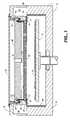
- FIG. 1is a sectional, partially schematic side view of a plasma chamber that includes the gas inlet manifold of the present invention.
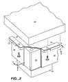
- FIG. 2is a partially exploded perspective view of a corner of the gas inlet manifold.
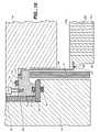
- FIG. 3is a transverse sectional view of a corner of the gas inlet manifold.
- FIG. 4is a vertical sectional view of one side of the gas inlet manifold.
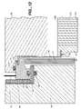
- FIG. 5is a vertical sectional view of a corner of the gas inlet manifold.
- FIG. 6is an exploded view of the corner shown in FIG. 2 .
- FIG. 7is a plan view of an alternative corner junction or coupler before it is folded.
- FIG. 8is an exploded view of a corner having the alternative coupler of FIG. 7 .
- FIG. 9is a view similar to FIG. 4 of an alternative embodiment having a gas inlet manifold in which a portion of the top flange of the flexible side wall is exposed to atmospheric pressure.
- FIG. 10is a detail of FIG. 9 .
- FIG. 11is a view similar to FIG. 2 of the alternative embodiment of FIG. 9 .
- FIG. 12is a view similar to FIG. 10 showing an electrical cable connected directly to the top flange of the side wall of the gas inlet manifold.
- FIG. 13is a partially exploded perspective view of a corner of an alternative gas inlet manifold in which the flexible side walls abut at the corners and the corner couplers are omitted.
- FIG. 1shows a plasma chamber that includes a gas inlet manifold 20 – 32 , also called a gas distribution manifold or plenum, according to the present invention.
- the illustrated chamberis suitable for performing plasma-assisted processes such as chemical vapor deposition (CVD) or etching on a large substrate. It is especially suitable for performing CVD processes for fabricating the electronic circuitry of a flat panel display on a glass substrate.
- CVDchemical vapor deposition
- the plasma chamber or vacuum chamberhas a housing or wall 10 , preferably composed of aluminum, that encircles the interior of the chamber.
- the chamber wall 10provides the vacuum enclosure for the side, and much of the bottom, of the chamber interior.
- a metal pedestal or susceptor 12functions as a cathode electrode and has a flat upper surface that supports a workpiece or substrate 14 .
- the substrateneed not directly contact the susceptor, but may be held slightly above the upper surface of the susceptor by, for example, a plurality of lift pins, not shown.
- An external gas supplydelivers one or more process gases to the process chamber.
- the chamberincludes a gas inlet manifold or plenum 20 – 32 (described in detail below) that encloses a region referred to as the manifold interior.
- a gas line or conduitextending from the external gas supply to a gas inlet aperture or orifice 30 in an outer wall or back wall 28 of the gas inlet manifold supplies the process gases into the manifold interior.
- the gasesthen flow out of the manifold through hundreds or thousands of orifices 22 in a gas distribution plate or diffuser plate 20 so as to enter the region of the chamber interior between the gas distribution plate and the susceptor 12 .
- a conventional vacuum pumpmaintains a desired level of vacuum within the chamber and exhausts the process gases and reaction products from the chamber through an annular exhaust slit 42 , then into annular exhaust plenum 44 , and then through an exhaust channel, not shown, to the pump.
- the gas distribution plate or diffuser plate 20is composed of an electrically conductive material, preferably aluminum, so that it can function as an anode electrode.
- An RF power supplynot shown, is connected between the gas distribution plate and the electrically grounded chamber components. A typical frequency for the RF power supply is 13 MHz. Because it is RF hot, the gas distribution plate 20 is electrically insulated from the lid by annular dielectric spacers 34 , 35 , 36 . The chamber side and bottom wall 10 and the lid 18 are connected to electrical ground.
- the susceptor or workpiece support pedestal 12typically is grounded also, but it optionally can be connected to a second RF power supply, commonly called the bias power supply.
- the RF power applied between the cathode electrode (the susceptor 12 ) and the anode electrode (the gas distribution plate 20 )produces an electromagnetic field in the region between the two electrodes that excites the gases in that region to a plasma state.
- the plasmaproduces reactive species from the process gas mixture that react with exposed material on the workpiece to perform the desired deposition or etch process.
- a dielectric liner 37is bolted to the underside of the lid 18 , and dielectric liner 38 covers the chamber side wall 10 .
- a dielectric liner 41occupies that gap.
- a removable lid 18rests atop the chamber side wall 10 so that the lid functions as an additional portion of the chamber wall.
- the gas inlet manifold 20 – 32rests on an annular, inwardly extending shelf of the lid.
- a cover 16is clamped to the top of the lid 18 . The only purpose of the cover is to protect human personnel from accidental contact with the portions of the gas inlet manifold that are RF hot, as described below.
- the chamber componentsshould be composed of materials that will not contaminate the semiconductor fabrication processes to be performed in the chamber and that will resist corrosion by the process gases.
- Aluminumis our preferred material for all of the components other than the dielectric spacers and liners 34 – 41 and the O-rings 45 – 48 .
- FIGS. 2–4show the gas inlet manifold or plenum in more detail.
- the gas inlet manifoldhas an interior region that is bounded on the bottom by the gas distribution plate or diffuser plate 20 , on the sides by the flexible side wall or suspension 24 , and on the top by the outer wall or back wall 28 . (The triangular corner post 58 shown in FIGS. 2 and 3 will be described later.)
- the gas distribution plate 20is an aluminum plate that is 3 cm thick. Preferably it should be thick enough so that it is not significantly deformed under atmospheric pressure when a vacuum is created within the chamber.
- the gas distribution plate 20is suspended by a thin, flexible side wall or suspension 24 , so that the suspension supports the entire weight of the gas distribution plate.
- the suspensionis flexible to minimize stress on the gas distribution plate in response to its thermal expansion and contraction.
- the upper end of the flexible side wallhas an upper lip 26 that is directly or indirectly mounted to and supported by the chamber wall 10 .
- directly mounting and supportwe mean that the upper end of the suspension may be supported by the chamber wall through intermediate components that are interposed between the upper lip 26 and the chamber wall 10 , such as the back wall 28 and the lid 18 in the embodiment of FIG. 1 .
- the back wall 28 of the gas inlet manifoldis mounted so as to abut the upper end 26 of the suspension, so that the back wall forms the upper boundary or enclosure of the interior region of the gas inlet manifold.
- the flexible side wall or suspension 24preferably consists of four distinct pieces of thin, flexible sheet metal, one on each of the four sides of the gas distribution plate.
- the four pieces or sides of the side wall or suspension 24collectively encircle the interior of the gas inlet manifold.
- the orifices 22 in the gas distribution plateshould have a diameter smaller than the width of the plasma dark space in order to prevent plasma within the plasma chamber from entering the region enclosed by the gas inlet manifold, i.e., the region between the gas distribution plate 20 and the back wall 28 .
- the width of the dark space, and therefore the optimum diameter of the orificesdepends on chamber pressure and other parameters of the specific semiconductor fabrication processes desired to be performed in the chamber.
- the gas inlet manifoldalso includes a gas inlet deflector consisting of a circular disc 32 having a diameter slightly greater than that of the gas inlet orifice 30 and suspended below the orifice by posts, not shown.
- the deflectorblocks gases from flowing in a straight path from the gas inlet 30 to the directly adjacent holes 22 in the center of the gas distribution plate, thereby helping to equalize the respective gas flow rates through the center and periphery of the gas distribution plate.
- Embodiment #1Back Wall Provides Vacuum Seal
- the upper surface of the back wall 28is the only component of the gas inlet manifold that is exposed to the ambient atmospheric pressure, hence the back wall is the only component of the gas inlet manifold that requires a vacuum seal.
- a vacuum seal between the chamber interior and the ambient atmosphere outside the chamberis provided by a first vacuum sealing material 45 between the back wall 28 and the dielectric spacer 34 , and by a second vacuum sealing material 46 between the dielectric 34 and a surface of the chamber wall.
- the latter surfaceis the surface of the lid 18 on which the dielectric rests.
- an additional vacuum sealing material 48is required between the lid and the chamber side wall 10 . Sealing materials 45 , 46 and 48 preferably are O-rings.
- a gas tight sealis not required between the back wall 28 and the upper lip 26 of the flexible side walls 24 .
- the only consequence of a gas leak at this junctionwould be that a small amount of process gas would enter the chamber interior through the leak rather than through the orifices 22 in the gas distribution plate 20 . Consequently, in the illustrated preferred embodiment there is no O-ring between the back wall 28 and the upper lip 26 of the flexible side wall.
- the upper lip 26is simply bolted to the back wall 28 by a plurality of bolts 72 spaced around the rim of the back wall. (See FIG. 4 .)
- the inlet manifold side walls 24are metal, they can provide good RF electrical contact between the gas distribution plate 20 and the back wall 28 . Therefore, the electrical cable that connects the gas distribution plate to the RF power supply can be attached directly to the outer surface of the back wall rather than to the distribution plate. Attaching the RF cable directly to the gas distribution plate would be undesirable because it would expose the RF connector to the potentially corrosive process gas mixture.
- the bolts 72help ensure good RF electrical contact between the upper lip 26 of the flexible side walls 24 , and the welds 56 help ensure good RF electrical contact between the lower lip 54 of the side walls and the gas distribution plate.
- Embodiment #2Upper Flange of Side Wall Also Provides Vacuum Seal
- the upper flange 70 of the flexible side wall or suspension 24 of the gas inlet manifoldis partially exposed to the external ambient atmosphere.
- the entire suspension 24including the upper lip 26
- the upper flange 70 of the flexible side wallmust contribute to the vacuum seal between the chamber interior and the external ambient atmosphere, which requires one more O-ring than the previous embodiments.
- two O-rings 45 , 46 or other sealing materialare required on either side of the dielectric spacer 34 , i.e., a first O-ring 45 between the dielectric and the upper flange 70 of the flexible side wall 24 , and a second O-ring 46 between the dielectric and the lid 18 .
- the present embodimentadditionally requires a third O-ring 47 or other sealing material between the upper flange 70 and the back wall 28 .
- the portion of the upper flange 70 in contact with the third O-ring 47must be continuous and uninterrupted around the complete circle of the O-ring (see FIG. 11 ), in contrast with the previous embodiments in which the upper lip 26 did not extend around any of the four corners of the gas inlet manifold.
- the upper flange 70preferably is shaped as a rectangular frame with an open center. It can be fabricated by cutting away or stamping the open center from a rectangular plate.
- the upper flange 70 of this embodimentreplaces the four reinforcing bars 27 of the previous embodiments.
- the upper flange 70preferably should have a smooth, flat upper surface abutting the back wall 28 .
- the upper lip 26preferably is attached (e.g., by weld 57 ) to the upper flange 70 at a shelf recessed below the upper surface of the flange.
- FIGS. 9–11we prefer to connect the RF cable directly to the upper surface of the back wall 28 .
- the bolts 72press the upper flange 70 of the suspension 24 against the back wall 28 and thereby help ensure good RF electrical contact between the back wall and the suspension.
- An important advantage of the present embodiment over the embodiments of FIGS. 1–8is that the bolts 72 can be located radially outward of the O-ring 47 . Consequently, the O-ring 47 protects the bolts 72 —and, most importantly, the adjacent areas of electrical contact between the back wall 28 and the upper flange 70 of the suspension—from exposure to the corrosive process gases and plasma within the chamber that eventually could degrade the electrical contact.
- FIGS. 9–11leaves the radially outer portion of the upper flange 70 uncovered by the back wall 28 . Therefore, this embodiment permits the electrical cable 74 from the RF power supply to be connected directly to the upper flange 70 at an area radially outward of the perimeter of the back wall 28 , as shown in FIG. 12 .
- the electrical cableis not connected to the back wall, there is no need to ensure a low impedance electrical contact between the side wall 24 and the back wall.
- the upper flange 70is mechanically mounted to the back wall 28 using the same bolts 72 as in the embodiment of FIGS. 9–11 , although the bolts are not shown in FIG. 12 .
- a novel and valuable function of the flexible side wall or suspension 24 of our inlet manifoldis that it minimizes mechanical stresses that could distort or crack the gas distribution plate or diffuser 20 when the diffuser undergoes thermal expansion and contraction.
- the gas distribution plateis referred to as the diffuser for brevity.
- the amount by which the diffuser 20 expandsis proportional to both the size of the diffuser and its temperature. Therefore, alleviating mechanical stress is most important with the larger diffusers required to process larger workpieces, such as large flat panel displays.
- the width of the diffuserwas 300 mm ⁇ 350 mm. For reasons described below, it is desirable to maintain the diffuser at 250° to 325° C. during the operation of a CVD process. We find that at such temperatures an aluminum diffuser expands by about one percent in each dimension, i.e., the width of our illustrative 300 mm ⁇ 350 mm diffuser expands by about 3 mm.
- the width of the diffuser 20expands and contracts in response to temperature changes during normal operation of the chamber, it forces the flexible side wall or suspension 24 to bend by some amount.
- the side wallshould be flexible enough to bend by that amount without substantial force.
- our inlet manifold suspension or side wall 24was sheet aluminum having a thickness of 1 mm and a height of 50 mm.
- the flexible side wall or suspension 24entirely of flexible sheet aluminum so that the side wall is flexible along its entire height, this is not required. It suffices for the suspension to include at least one flexible portion somewhere between the upper end 26 and the lower end 54 .
- Design parameters that reduce the bending forceare: (1) selecting a more flexible material for the flexible portion of the suspension; (2) decreasing the thickness of the flexible portion; and (3) increasing the length (i.e., height) of the flexible portion.
- length or heightwe mean the dimension of the flexible portion of the side wall along the direction perpendicular to the plane of the diffuser.
- the side wall or suspension 24should be flexible enough (i.e., sufficiently thin and long) to bend at least 1.7 degrees without exerting substantial force on the diffuser. As stated above, such bending force preferably should not distort the shape of the diffuser by more than 10 or 25 microns.
- the substrate 14 and the diffuser 20are rectangular.
- the flexible side wall 24can be a single, unbroken annulus with a rectangular cross section, an unbroken design is not preferred because thermally induced mechanical expansion and contraction of the diffuser would produce excessive stress at the corners of the side wall 24 .
- Our preferred design for avoiding such stressis to divide the flexible side wall into four segments or pieces, one for each side of the rectangular diffuser, and to provide at each corner a novel expansion joint that allows only a negligible amount of gas to leak at the joint.
- the inlet manifold side wall or suspension 24preferably consists of four distinct pieces of thin, flexible sheet aluminum respectively located at the four sides of the rectangular inlet manifold.
- Each of the four sides 24preferably is formed from a flat, rectangular piece of sheet metal whose upper end is bent 90° to form an outwardly extending upper lip 26 , and whose lower end is bent 90° to form an inwardly extending lower flange 54 .
- the lower flangepreferably is attached to the diffuser 20 by being inserted in a groove in the diffuser and then reinforced by a weld bead 54 .
- Each of the four lips 26is reinforced by a rigid bar 27 , preferably a 5 mm thick aluminum bar.
- Each reinforcing bar 27is bolted to the underside of the back wall 28 , and the corresponding upper lip 26 is sandwiched between the reinforcing bar and the back wall, thereby clamping the upper lip to the back wall.
- a grooveextends almost the entire width of each of the four sides of the diffuser ( FIG. 2 ).
- Each of the four side wall pieces 24has a right angle bend at its lower end, and the inwardly extending portion 54 below the bend constitutes a lower mounting flange that fits into the corresponding groove of the diffuser ( FIG. 4 ).
- One or more weld beads 56is welded to the lower mounting flange 54 and the diffuser 20 to secure them together.
- the inlet manifold side wall 24since the preferred embodiment implements the inlet manifold side wall 24 as four separate segments or pieces, two adjacent side wall pieces will meet near each of the four corners of the diffuser. A junction or seal between the edges of adjacent side wall pieces 24 should be provided at each corner so that excessive process gas does not leak from the inlet manifold into the chamber at the junction. To preserve the benefit of our flexible inlet manifold side wall in accommodating thermal expansion of the diffuser, the junction should accommodate flexing of the inlet manifold side wall as the diffuser expands and contracts.
- FIGS. 2 , 3 and 6show our preferred junction at each of the four corners of the diffuser.
- Both ends 60 of each of the four side wall pieces 24are bent inward at a 45 degree angle so that, at a given corner, the respective ends of the two adjacent side wall pieces 24 are coplanar.
- a moderately gas-tight seal between the adjacent ends 60is accomplished by a slotted cover or coupler 62 , 64 that slips over the two ends 60 .
- the coupleris fabricated by welding together two pieces of sheet aluminum along a vertical center seam, and bending one coupler piece 62 so as to create a slot between it and the other coupler piece 64 .
- the slotted coupleris installed by slipping it over the two ends 60 so that the seam of the coupler is approximately centered in the gap between the two ends 60 , and so that each end 60 fits snugly in a corresponding one of the two slots of the coupler.
- the slotis sized to fit around the end 60 with sufficient snugness so that it permits an amount of gas leakage from the inlet manifold to the chamber that is no more than a small fraction of the intended gas flow through the perforations 22 . Nevertheless, the slot is sized large enough to permit radial movement of the ends 60 as the diffuser expands and contracts.
- FIGS. 7 and 8show an alternative design for the slotted cover or coupler consisting of a single, rectangular piece of sheet metal 66 .
- a pair of rectangular notchesis cut out as shown in FIG. 7 so as to leave only a thin bridge 68 between two halves of the coupler 66 .
- the coupler 66is folded in half at the bridge as shown in FIG. 8 .
- the width W of the bridge 68is narrow enough to slide between the two ends 60 of the two inlet manifold side walls that meet at a corner.
- the slotted coupler 66is installed in the same manner as the previously described coupler 62 , 64 : by sliding the coupler 66 over the two ends 60 .
- the length L of the bridge 68determines the gap between the two halves of the coupler 66 when it is folded as shown in FIG. 8 .
- This gapshould be large enough to permit movement of the ends 60 as the inlet manifold side wall flexes in response to expansion and contraction of the diffuser, but it should be small enough so that the two halves of the slotted coupler 66 fit snugly around the ends 60 so as to minimize gas leakage as described in the preceding paragraph.
- Our preferred embodimentadditionally includes in each of the four corners of the gas inlet manifold a stationary corner support post 58 having a triangular cross section as shown in FIGS. 2 , 3 , 5 and 6 .
- the corner support postis bolted to the diffuser 20 as shown in FIGS. 5 and 6 , and it is spaced outward from the slotted coupler 62 , 64 so as to not interfere with movement of the slotted coupler as the diffuser expands and contracts.
- the corner support posthas no function during operation of the plasma chamber, and it therefore can be omitted.
- the four corner covers or couplers 60 – 66can be omitted simply by extending each of the four pieces of the flexible side walls 24 so that they abut at the four corners of the diffuser.
- This simplified designmay produce more leakage of process gas at the corners, but in many applications the amount of leakage may be so small as to not significantly affect the plasma process being performed on the workpiece.
- the diffuser 20preferably should be circular in cross section, rather than rectangular as in the preceding examples.
- the flexible suspension or side wall 24 of the gas inlet manifoldcould be a single, unbroken piece having an annular shape.
- the flexibility of the suspensioncould be increased by dividing it into any number of axially extending segments separated by small axially extending gaps, similar to the four segments of the rectangular side wall in the previously discussed embodiments.
- O-rings 45 – 48To ensure a reliable vacuum seal between the chamber interior and the external atmosphere, it is important to protect the O-rings 45 – 48 from excessive temperature.
- Low cost O-ringse.g., composed of Viton elastomer typically are rated by their manufacturers at 250° C. or less, and some experts believe such O-rings should be maintained at or below 100° C. to maximize their reliability.
- the O-rings 46 and 48directly contact the lid 18 , and O-ring 47 directly contacts the back wall 28 of the gas inlet manifold, hence the temperatures of these O-rings are expected to be about the same as the respective temperatures of the lid and back wall.
- the O-ring 45directly contacts the back wall
- the O-ring 45directly contacts the upper flange 70 of the suspension 24 . Because the upper flange preferably is mounted in good thermal contact with the back wall, the O-ring 45 in this embodiment is expected to be only slightly hotter than the other O-rings.
- the chamber side wall 10can be further cooled by surrounding it with a water jacket, not shown, through which cool water can be pumped.
- the lid 18 , back wall 28 and cover 16can be cooled by pumping the same water through a sealed water jacket (not shown) mounted on the upper surface of the back wall 28 , below the cover 16 .
- Such water coolingcan prevent the temperatures of the O-rings 45 – 48 from exceeding 100° C.
- a dielectricshould be interposed between the water jacket and the back wall.
- a thicker dielectriccan be selected if it is desired to increase the temperature differential between the water jacket and the back wall. This may be useful in applications in which it is desired to maintain the back wall at a temperature substantially higher than the temperature of the water, such as a temperature over 100° C. Maintaining the back wall at such a high temperature would help elevate the temperature of the gas distribution plate, which can be advantageous for reasons explained in the next paragraph.
- the gas distribution plateis bolted directly to a chamber lid or side wall that has high thermal mass and high thermal conductivity, so that the lid or side wall functions as a heat sink drawing heat away from the distribution plate.
- our novel inlet manifold side wall 24can thermally isolate the gas distribution plate by providing thermal resistance between the gas distribution plate and the other chamber components such as the lid 18 and chamber wall 10 . Therefore, our gas distribution plate can operate at a higher temperature than conventional designs.
- our inlet manifold side wall 24(or a portion thereof) is sufficiently thin, and has sufficient length or height, so that the thermal resistance of the side wall 24 (or such portion) is large enough to provide a substantial temperature difference between the gas distribution plate and the chamber components to which it is mounted, i.e., the back wall 28 , the chamber lid 18 , the chamber side wall 10 , and the O-rings 45 – 47 .
- length or heightwe mean a dimension along the direction perpendicular to the plane of the gas distribution plate.
- the inlet manifold side wallis sheet aluminum having a thickness of 1 mm and a height of 5 cm.
- Our preferred temperature for the gas distribution plate 20 while performing a plasma CVD processis at least 200° C., preferably 250° to 325° C., and most preferably about 300° C.
- Our inlet manifold side wall 24has sufficient thermal resistance to allow the gas distribution plate to reach such temperatures while the outer chamber components do not exceed 100° to 140° C.
- the chamber wall 10 , lid 18 , and inlet manifold back wall 28can be considered to function as heat sinks to maintain the O-rings 45 – 48 at a sufficiently low temperature.
- the temperature differential across the inlet manifold side wall 24is about 160° C.
- our inventioncontemplates that the side wall thickness and height preferably should be sufficiently small and large, respectively, so that such temperature differential is at least 100° C. after the chamber components reach their normal operating temperatures during plasma processing.
- thermal isolation of the gas distribution plate 20can be achieved by increasing the thermal resistance of one or both of the following two contact areas: (1) the area of contact between the suspension and the gas distribution plate, and (2) the area of contact between the suspension and other chamber components that are thermally coupled to the chamber wall.
- the thermal resistance between the suspension and the gas distribution platecan be increased by reducing the surface area covered by the weld beads 56 between the gas distribution plate and the lower flange 54 of the suspension ( FIGS. 4 and 10 ).
- the thermal resistance between the suspension and the other chamber componentscan be increased by reducing the surface area covered by the weld beads 57 between the upper lip 26 and the flange 70 of the suspension.
- a possible implementationwould be to apply only six or eight weld beads 56 or 57 that are each only one-half inch in width along the circumference of the suspension. Since the weld beads also conduct RF power to the gas distribution plate, they should be uniformly spaced around the circumference of the suspension 24 to ensure uniform RF power distribution.
Landscapes
- Chemical & Material Sciences (AREA)
- Engineering & Computer Science (AREA)
- General Chemical & Material Sciences (AREA)
- Chemical Kinetics & Catalysis (AREA)
- Materials Engineering (AREA)
- Mechanical Engineering (AREA)
- Metallurgy (AREA)
- Organic Chemistry (AREA)
- Physics & Mathematics (AREA)
- Plasma & Fusion (AREA)
- Analytical Chemistry (AREA)
- Condensed Matter Physics & Semiconductors (AREA)
- General Physics & Mathematics (AREA)
- Manufacturing & Machinery (AREA)
- Computer Hardware Design (AREA)
- Microelectronics & Electronic Packaging (AREA)
- Power Engineering (AREA)
- Drying Of Semiconductors (AREA)
- Chemical Vapour Deposition (AREA)
- Physical Or Chemical Processes And Apparatus (AREA)
- Plasma Technology (AREA)
Abstract
Description
This patent application is a divisional of application Ser. No. 10/293,544 filed Nov. 12, 2002, now U.S. Pat. No. 6,823,589 which is a divisional of Ser. No. 09/488,612 filed Jan. 20, 2000, now U.S. Pat. No. 6,477,980 issued Nov. 12, 2002.
The invention relates generally to gas distribution manifolds for supplying gas to a plasma chamber. More specifically, the invention relates to such a manifold having a perforated gas distribution plate suspended by flexible side walls which accommodate thermal expansion of the plate.
Electronic devices, such as flat panel displays and integrated circuits, commonly are fabricated by a series of process steps in which layers are deposited on a substrate and the deposited material is etched into desired patterns. The process steps commonly include plasma enhanced chemical vapor deposition (CVD) processes and plasma etch processes.
Plasma processes require supplying a process gas mixture to a vacuum chamber called a plasma chamber, and then applying electrical or electromagnetic power to excite the process gas to a plasma state. The plasma decomposes the gas mixture into ion species that perform the desired deposition or etch process.
In capacitively excited CVD chambers, the plasma is excited by RF power applied between an anode electrode and a cathode electrode. Generally the substrate is mounted on a pedestal or susceptor that functions as the cathode electrode, and the anode electrode is mounted a short distance from, and parallel to, the substrate. Commonly the anode electrode also functions as a gas distribution plate for supplying the process gas mixture into the chamber. The anode electrode is perforated with hundreds or thousands of orifices through which the process gas mixture flows into the gap between the anode and cathode. The orifices are spaced across the surface of the gas distribution plate so as to maximize the spatial uniformity of the process gas mixture adjacent the substrate. Such a gas distribution plate, also called a diffuser plate or “shower head”, is described in commonly assigned U.S. Pat. No. 4,854,263 issued Aug. 8, 1989 to Chang et al.
Perforated gas distribution plates typically are rigidly mounted to the lid or upper wall of the plasma chamber. Rigid mounting has the disadvantage of not accommodating thermal expansion of the perforated plate as it acquires heat from the plasma. The consequent mechanical stresses on the plate can distort or crack the plate. Alleviating mechanical stress is most important with the larger distribution plates required to process larger workpieces, such as large flat panel displays. Therefore, a need exists for a gas distribution device that minimizes such thermally induced mechanical stresses.
Another shortcoming of conventional gas distribution plates is that they generally remain cool during the CVD process, hence they contribute to undesirable heat loss from the surface of the substrate. Specifically, conventional gas distribution plates generally are bolted directly to a chamber lid or side wall that has high thermal mass and high thermal conductivity, so that the lid or side wall functions as a heat sink drawing heat away from the distribution plate. Therefore, conventional designs typically maintain the gas distribution plate at an undesirably low temperature.
The invention is a gas inlet manifold for a plasma chamber. The manifold has a perforated gas distribution plate suspended by a flexible side wall which accommodates thermal expansion or contraction of the gas distribution plate. The invention is advantageous to avoid distortion or cracking of the gas distribution plate in response to such thermal expansion or contraction.
The invention is a method of suspending a gas distribution plate from a plurality of side wall segments separated by gaps. One aspect of the invention includes positioning a novel sealing cover that minimizes gas leakage through the gaps while permitting movement of the flexible side wall segments. In another aspect of the invention, each of two adjacent side wall segments has a side portion in which a bend is formed so that the side portions of the two adjacent side wall segments are coplanar.
In another aspect, the invention is facilitates operation of the perforated gas distribution plate at an elevated temperature. The gas distribution plate is suspended from the chamber wall by inlet manifold side walls. The inlet manifold side walls interpose substantial thermal impedance between the gas distribution plate and the chamber wall, thereby allowing the gas distribution plate to increase in temperature. This aspect of the invention is advantageous to help reduce heat loss from the exposed surface of the workpiece during operation of the chamber.
Plasma Chamber Overview
The plasma chamber or vacuum chamber has a housing orwall 10, preferably composed of aluminum, that encircles the interior of the chamber. Thechamber wall 10 provides the vacuum enclosure for the side, and much of the bottom, of the chamber interior. A metal pedestal orsusceptor 12 functions as a cathode electrode and has a flat upper surface that supports a workpiece orsubstrate 14. Alternatively, the substrate need not directly contact the susceptor, but may be held slightly above the upper surface of the susceptor by, for example, a plurality of lift pins, not shown.
An external gas supply, not shown, delivers one or more process gases to the process chamber. Specifically, the chamber includes a gas inlet manifold orplenum 20–32 (described in detail below) that encloses a region referred to as the manifold interior. A gas line or conduit extending from the external gas supply to a gas inlet aperture ororifice 30 in an outer wall orback wall 28 of the gas inlet manifold supplies the process gases into the manifold interior. The gases then flow out of the manifold through hundreds or thousands oforifices 22 in a gas distribution plate ordiffuser plate 20 so as to enter the region of the chamber interior between the gas distribution plate and thesusceptor 12.
A conventional vacuum pump, not shown, maintains a desired level of vacuum within the chamber and exhausts the process gases and reaction products from the chamber through an annular exhaust slit42, then intoannular exhaust plenum 44, and then through an exhaust channel, not shown, to the pump.
The gas distribution plate ordiffuser plate 20 is composed of an electrically conductive material, preferably aluminum, so that it can function as an anode electrode. An RF power supply, not shown, is connected between the gas distribution plate and the electrically grounded chamber components. A typical frequency for the RF power supply is 13 MHz. Because it is RF hot, thegas distribution plate 20 is electrically insulated from the lid by annulardielectric spacers bottom wall 10 and thelid 18 are connected to electrical ground. The susceptor orworkpiece support pedestal 12 typically is grounded also, but it optionally can be connected to a second RF power supply, commonly called the bias power supply.
The RF power applied between the cathode electrode (the susceptor12) and the anode electrode (the gas distribution plate20) produces an electromagnetic field in the region between the two electrodes that excites the gases in that region to a plasma state. The plasma produces reactive species from the process gas mixture that react with exposed material on the workpiece to perform the desired deposition or etch process.
To concentrate the plasma in the region of the chamber between the workpiece14 and thegas distribution plate 20, other metal surfaces in the chamber that are near the distribution plate preferably are covered with dielectric liners. Specifically, adielectric liner 37 is bolted to the underside of thelid 18, anddielectric liner 38 covers thechamber side wall 10. To prevent plasma formation, and to minimize RF power conduction, in the annular gap between the gas inlet manifold and the lid, adielectric liner 41 occupies that gap.
Aremovable lid 18 rests atop thechamber side wall 10 so that the lid functions as an additional portion of the chamber wall. Thegas inlet manifold 20–32 rests on an annular, inwardly extending shelf of the lid. Acover 16 is clamped to the top of thelid 18. The only purpose of the cover is to protect human personnel from accidental contact with the portions of the gas inlet manifold that are RF hot, as described below.
The chamber components should be composed of materials that will not contaminate the semiconductor fabrication processes to be performed in the chamber and that will resist corrosion by the process gases. Aluminum is our preferred material for all of the components other than the dielectric spacers andliners 34–41 and the O-rings 45–48.
All portions of the plasma chamber other than the gas inlet manifold are conventional. The design and operation of conventional plasma CVD and etch chambers are described in the following commonly-assigned U.S. patents, the entire content of each of which is hereby incorporated by reference in this patent specification: U.S. Pat. No. 5,844,205 issued Dec. 1,1998 to White et al.; and U.S. Pat. No. 4,854,263 issued Aug. 8, 1989 to Chang et al.
Gas Inlet Manifold
In the illustrated embodiments, thegas distribution plate 20 is an aluminum plate that is 3 cm thick. Preferably it should be thick enough so that it is not significantly deformed under atmospheric pressure when a vacuum is created within the chamber.
In our novel gas inlet manifold design, thegas distribution plate 20 is suspended by a thin, flexible side wall orsuspension 24, so that the suspension supports the entire weight of the gas distribution plate. As explained in the section below entitled “Accommodating Thermally Induced Mechanical Expansion/Contraction”, the suspension is flexible to minimize stress on the gas distribution plate in response to its thermal expansion and contraction. The upper end of the flexible side wall has anupper lip 26 that is directly or indirectly mounted to and supported by thechamber wall 10. By “indirect” mounting and support, we mean that the upper end of the suspension may be supported by the chamber wall through intermediate components that are interposed between theupper lip 26 and thechamber wall 10, such as theback wall 28 and thelid 18 in the embodiment ofFIG. 1 .
Theback wall 28 of the gas inlet manifold is mounted so as to abut theupper end 26 of the suspension, so that the back wall forms the upper boundary or enclosure of the interior region of the gas inlet manifold.
In the illustrated embodiments having a rectangulargas distribution plate 20, the flexible side wall orsuspension 24 preferably consists of four distinct pieces of thin, flexible sheet metal, one on each of the four sides of the gas distribution plate. The four pieces or sides of the side wall orsuspension 24 collectively encircle the interior of the gas inlet manifold.
Theorifices 22 in the gas distribution plate should have a diameter smaller than the width of the plasma dark space in order to prevent plasma within the plasma chamber from entering the region enclosed by the gas inlet manifold, i.e., the region between thegas distribution plate 20 and theback wall 28. The width of the dark space, and therefore the optimum diameter of the orifices, depends on chamber pressure and other parameters of the specific semiconductor fabrication processes desired to be performed in the chamber. Alternatively, to perform plasma processes using reagent gases that are especially difficult to dissociate, it may be desirable to employ orifices having a narrow inlet and a wider, flared outlet as described in the above-referenced U.S. Pat. No. 4,854,263 to Chang et al.
Preferably the gas inlet manifold also includes a gas inlet deflector consisting of acircular disc 32 having a diameter slightly greater than that of thegas inlet orifice 30 and suspended below the orifice by posts, not shown. The deflector blocks gases from flowing in a straight path from thegas inlet 30 to the directlyadjacent holes 22 in the center of the gas distribution plate, thereby helping to equalize the respective gas flow rates through the center and periphery of the gas distribution plate.
Embodiment #1—Back Wall Provides Vacuum Seal
In the embodiments shown inFIGS. 1–8 , the upper surface of theback wall 28 is the only component of the gas inlet manifold that is exposed to the ambient atmospheric pressure, hence the back wall is the only component of the gas inlet manifold that requires a vacuum seal. Specifically, a vacuum seal between the chamber interior and the ambient atmosphere outside the chamber is provided by a firstvacuum sealing material 45 between theback wall 28 and thedielectric spacer 34, and by a secondvacuum sealing material 46 between the dielectric34 and a surface of the chamber wall. In the illustrated embodiments, the latter surface is the surface of thelid 18 on which the dielectric rests. Because the illustrated embodiments include aremovable lid 18, an additionalvacuum sealing material 48 is required between the lid and thechamber side wall 10.Sealing materials
In this embodiment, a gas tight seal is not required between theback wall 28 and theupper lip 26 of theflexible side walls 24. The only consequence of a gas leak at this junction would be that a small amount of process gas would enter the chamber interior through the leak rather than through theorifices 22 in thegas distribution plate 20. Consequently, in the illustrated preferred embodiment there is no O-ring between theback wall 28 and theupper lip 26 of the flexible side wall. Theupper lip 26 is simply bolted to theback wall 28 by a plurality ofbolts 72 spaced around the rim of the back wall. (SeeFIG. 4 .)
Because the inletmanifold side walls 24 are metal, they can provide good RF electrical contact between thegas distribution plate 20 and theback wall 28. Therefore, the electrical cable that connects the gas distribution plate to the RF power supply can be attached directly to the outer surface of the back wall rather than to the distribution plate. Attaching the RF cable directly to the gas distribution plate would be undesirable because it would expose the RF connector to the potentially corrosive process gas mixture. Thebolts 72 help ensure good RF electrical contact between theupper lip 26 of theflexible side walls 24, and thewelds 56 help ensure good RF electrical contact between thelower lip 54 of the side walls and the gas distribution plate.
Embodiment #2—Upper Flange of Side Wall Also Provides Vacuum Seal
In an alternative embodiment shown inFIGS. 9–11 , theupper flange 70 of the flexible side wall orsuspension 24 of the gas inlet manifold is partially exposed to the external ambient atmosphere. This contrasts with the embodiments ofFIGS. 1–8 in which theentire suspension 24, including theupper lip 26, is completely enclosed by the perimeter of theback wall 28 of the gas inlet manifold. Consequently, in the embodiment ofFIGS. 9–11 , theupper flange 70 of the flexible side wall must contribute to the vacuum seal between the chamber interior and the external ambient atmosphere, which requires one more O-ring than the previous embodiments.
As in the previous embodiments, two O-rings dielectric spacer 34, i.e., a first O-ring 45 between the dielectric and theupper flange 70 of theflexible side wall 24, and a second O-ring 46 between the dielectric and thelid 18. Unlike the previous embodiments, the present embodiment additionally requires a third O-ring 47 or other sealing material between theupper flange 70 and theback wall 28.
In order to effect a vacuum seal between theupper flange 70 and theback wall 28, the portion of theupper flange 70 in contact with the third O-ring 47 must be continuous and uninterrupted around the complete circle of the O-ring (seeFIG. 11 ), in contrast with the previous embodiments in which theupper lip 26 did not extend around any of the four corners of the gas inlet manifold.
There is no need for the flexible side wall orsuspension 24 to be continuous and uninterrupted, since it is not part of the vacuum seal between the chamber interior and the external ambient atmosphere. Therefore, it can be four distinct pieces as in the previous embodiments.
A plurality ofbolts 72 spaced around the rim of theback wall 28 attach theupper flange 70 of thesuspension 24 to the back wall.
Theupper flange 70 preferably is shaped as a rectangular frame with an open center. It can be fabricated by cutting away or stamping the open center from a rectangular plate. Theupper flange 70 of this embodiment replaces the four reinforcingbars 27 of the previous embodiments. Theupper flange 70 preferably should have a smooth, flat upper surface abutting theback wall 28. To prevent theupper lip 26 of thesuspension 24 from projecting above the plane of this upper surface, theupper lip 26 preferably is attached (e.g., by weld57) to theupper flange 70 at a shelf recessed below the upper surface of the flange.
As in the previously discussed embodiments ofFIGS. 1–8 , in our preferred embodiment ofFIGS. 9–11 we prefer to connect the RF cable directly to the upper surface of theback wall 28. Thebolts 72 press theupper flange 70 of thesuspension 24 against theback wall 28 and thereby help ensure good RF electrical contact between the back wall and the suspension. An important advantage of the present embodiment over the embodiments ofFIGS. 1–8 is that thebolts 72 can be located radially outward of the O-ring 47. Consequently, the O-ring 47 protects thebolts 72—and, most importantly, the adjacent areas of electrical contact between theback wall 28 and theupper flange 70 of the suspension—from exposure to the corrosive process gases and plasma within the chamber that eventually could degrade the electrical contact.
Unlike the embodiments ofFIGS. 1–8 , the embodiment ofFIGS. 9–11 leaves the radially outer portion of theupper flange 70 uncovered by theback wall 28. Therefore, this embodiment permits theelectrical cable 74 from the RF power supply to be connected directly to theupper flange 70 at an area radially outward of the perimeter of theback wall 28, as shown inFIG. 12 . In this alternative implementation, because the electrical cable is not connected to the back wall, there is no need to ensure a low impedance electrical contact between theside wall 24 and the back wall. Preferably, in theFIG. 12 embodiment theupper flange 70 is mechanically mounted to theback wall 28 using thesame bolts 72 as in the embodiment ofFIGS. 9–11 , although the bolts are not shown inFIG. 12 .
Accommodating Thermally Induced Mechanical Expansion/Contraction
A novel and valuable function of the flexible side wall orsuspension 24 of our inlet manifold is that it minimizes mechanical stresses that could distort or crack the gas distribution plate ordiffuser 20 when the diffuser undergoes thermal expansion and contraction. (The gas distribution plate is referred to as the diffuser for brevity.) The amount by which thediffuser 20 expands is proportional to both the size of the diffuser and its temperature. Therefore, alleviating mechanical stress is most important with the larger diffusers required to process larger workpieces, such as large flat panel displays. In our prototype the width of the diffuser was 300 mm×350 mm. For reasons described below, it is desirable to maintain the diffuser at 250° to 325° C. during the operation of a CVD process. We find that at such temperatures an aluminum diffuser expands by about one percent in each dimension, i.e., the width of our illustrative 300 mm×350 mm diffuser expands by about 3 mm.
When the width of thediffuser 20 expands and contracts in response to temperature changes during normal operation of the chamber, it forces the flexible side wall orsuspension 24 to bend by some amount. The side wall should be flexible enough to bend by that amount without substantial force. In particular, the bending force between the diffuser and the side wall should be low enough to avoid cracking or distorting the diffuser. More specifically, the bending force should be low enough to prevent distorting the shape of the diffuser by more than 0.1 mm=100 microns, more preferably by no more than 0.025 mm=25 microns, and most preferably by no more than 0.01 mm=10 microns. It is especially important to avoid more than this amount of distortion of the flatness or contour of the surface of the diffuser that faces thesubstrate 14.
In the successfully tested embodiment ofFIG. 1 , our inlet manifold suspension orside wall 24 was sheet aluminum having a thickness of 1 mm and a height of 50 mm.
Although it is simplest to construct the flexible side wall orsuspension 24 entirely of flexible sheet aluminum so that the side wall is flexible along its entire height, this is not required. It suffices for the suspension to include at least one flexible portion somewhere between theupper end 26 and thelower end 54.
Design parameters that reduce the bending force are: (1) selecting a more flexible material for the flexible portion of the suspension; (2) decreasing the thickness of the flexible portion; and (3) increasing the length (i.e., height) of the flexible portion. By length or height we mean the dimension of the flexible portion of the side wall along the direction perpendicular to the plane of the diffuser.
As stated above, in response to heating during operation of the chamber, our 300 mm×350 mm diffuser expanded in width by one percent or 3 mm. Therefore, each of the four side walls was laterally deflected by half this amount, which is 1.5 mm. The angle at which each side wall bends is the lateral deflection of the side wall divided by the height of the side wall, which in this example is 1.5 mm/ 50 mm=0.03 radians=1.7 degrees. Therefore, in our example, the side wall orsuspension 24 should be flexible enough (i.e., sufficiently thin and long) to bend at least 1.7 degrees without exerting substantial force on the diffuser. As stated above, such bending force preferably should not distort the shape of the diffuser by more than 10 or 25 microns.
In the illustrated preferred embodiment, thesubstrate 14 and thediffuser 20 are rectangular. Although theflexible side wall 24 can be a single, unbroken annulus with a rectangular cross section, an unbroken design is not preferred because thermally induced mechanical expansion and contraction of the diffuser would produce excessive stress at the corners of theside wall 24. Our preferred design for avoiding such stress is to divide the flexible side wall into four segments or pieces, one for each side of the rectangular diffuser, and to provide at each corner a novel expansion joint that allows only a negligible amount of gas to leak at the joint.
Specifically, the inlet manifold side wall orsuspension 24 preferably consists of four distinct pieces of thin, flexible sheet aluminum respectively located at the four sides of the rectangular inlet manifold. (SeeFIGS. 2 and 3 .) Each of the foursides 24 preferably is formed from a flat, rectangular piece of sheet metal whose upper end is bent 90° to form an outwardly extendingupper lip 26, and whose lower end is bent 90° to form an inwardly extendinglower flange 54. (SeeFIG. 4 .) The lower flange preferably is attached to thediffuser 20 by being inserted in a groove in the diffuser and then reinforced by aweld bead 54.
Each of the fourlips 26 is reinforced by arigid bar 27, preferably a 5 mm thick aluminum bar. Each reinforcingbar 27 is bolted to the underside of theback wall 28, and the correspondingupper lip 26 is sandwiched between the reinforcing bar and the back wall, thereby clamping the upper lip to the back wall.
To attach the diffuser to the inlet manifoldside wall pieces 24, a groove extends almost the entire width of each of the four sides of the diffuser (FIG. 2 ). Each of the fourside wall pieces 24 has a right angle bend at its lower end, and the inwardly extendingportion 54 below the bend constitutes a lower mounting flange that fits into the corresponding groove of the diffuser (FIG. 4 ). One ormore weld beads 56 is welded to the lower mountingflange 54 and thediffuser 20 to secure them together.
Since the preferred embodiment implements the inletmanifold side wall 24 as four separate segments or pieces, two adjacent side wall pieces will meet near each of the four corners of the diffuser. A junction or seal between the edges of adjacentside wall pieces 24 should be provided at each corner so that excessive process gas does not leak from the inlet manifold into the chamber at the junction. To preserve the benefit of our flexible inlet manifold side wall in accommodating thermal expansion of the diffuser, the junction should accommodate flexing of the inlet manifold side wall as the diffuser expands and contracts.
Our preferred embodiment additionally includes in each of the four corners of the gas inlet manifold a stationarycorner support post 58 having a triangular cross section as shown inFIGS. 2 ,3,5 and6. The corner support post is bolted to thediffuser 20 as shown inFIGS. 5 and 6 , and it is spaced outward from the slottedcoupler thin side walls 24 from collapsing when the gasinlet manifold assembly 20–32 is stored outside the plasma chamber, for example when the manifold assembly is stored as a spare part, or when it is removed from the plasma chamber to permit maintenance of the chamber.
In an alternative design shown inFIG. 13 , the four corner covers orcouplers 60–66 can be omitted simply by extending each of the four pieces of theflexible side walls 24 so that they abut at the four corners of the diffuser. This simplified design may produce more leakage of process gas at the corners, but in many applications the amount of leakage may be so small as to not significantly affect the plasma process being performed on the workpiece.
In a chamber intended to process acircular workpiece 14 such as a silicon wafer, thediffuser 20 preferably should be circular in cross section, rather than rectangular as in the preceding examples. In that case, the flexible suspension orside wall 24 of the gas inlet manifold could be a single, unbroken piece having an annular shape. Alternatively, the flexibility of the suspension could be increased by dividing it into any number of axially extending segments separated by small axially extending gaps, similar to the four segments of the rectangular side wall in the previously discussed embodiments.
While thermal expansion of the diffuser is not a severe problem in the chambers most commonly used today for processing 200 mm diameter silicon wafers, thermal expansion will become more significant as the industry moves to larger diameter wafers, and hence larger diameter diffusers. Therefore, this is an important prospective application of the invention.
Thermal Isolation
To ensure a reliable vacuum seal between the chamber interior and the external atmosphere, it is important to protect the O-rings 45–48 from excessive temperature. Low cost O-rings (e.g., composed of Viton elastomer) typically are rated by their manufacturers at 250° C. or less, and some experts believe such O-rings should be maintained at or below 100° C. to maximize their reliability.
The O-rings lid 18, and O-ring 47 directly contacts theback wall 28 of the gas inlet manifold, hence the temperatures of these O-rings are expected to be about the same as the respective temperatures of the lid and back wall. In the first embodiment, the O-ring 45 directly contacts the back wall, whereas in the second embodiment (FIGS. 9–11 ) the O-ring 45 directly contacts theupper flange 70 of thesuspension 24. Because the upper flange preferably is mounted in good thermal contact with the back wall, the O-ring 45 in this embodiment is expected to be only slightly hotter than the other O-rings.
We find that simple exposure to the ambient atmosphere suffices to maintain thelid 18 andchamber wall 10 at temperatures of 100° to 140° C. The inletmanifold back wall 28 generally is cooler because it has no direct exposure to heat radiation from the plasma within the chamber. Therefore, we expect the temperatures of the O-rings 45–48 will not exceed 140° C. This temperature is low enough that we do not believe any additional cooling, such as water cooling, is required.
Optionally, however, thechamber side wall 10 can be further cooled by surrounding it with a water jacket, not shown, through which cool water can be pumped. Similarly, thelid 18,back wall 28 and cover16 can be cooled by pumping the same water through a sealed water jacket (not shown) mounted on the upper surface of theback wall 28, below thecover 16. Such water cooling can prevent the temperatures of the O-rings 45–48 from exceeding 100° C.
Since theback wall 28 of the gas inlet manifold is RF powered, a dielectric should be interposed between the water jacket and the back wall. A thicker dielectric can be selected if it is desired to increase the temperature differential between the water jacket and the back wall. This may be useful in applications in which it is desired to maintain the back wall at a temperature substantially higher than the temperature of the water, such as a temperature over 100° C. Maintaining the back wall at such a high temperature would help elevate the temperature of the gas distribution plate, which can be advantageous for reasons explained in the next paragraph.
While low temperature is important for the O-rings, it is undesirable for the gas distribution plate ordiffuser 20. Elevating the temperature of the gas distribution plate to 250° to 325° C. is advantageous to reduce heat loss from the surface of thesubstrate 14. Also, if it is desired to use a conventional in situ plasma process for cleaning residue from the interior of the chamber, the cleaning of the gas distribution plate is accelerated if the temperature of the gas distribution plate is elevated.
In conventional designs, the gas distribution plate is bolted directly to a chamber lid or side wall that has high thermal mass and high thermal conductivity, so that the lid or side wall functions as a heat sink drawing heat away from the distribution plate. In contrast, our novel inletmanifold side wall 24 can thermally isolate the gas distribution plate by providing thermal resistance between the gas distribution plate and the other chamber components such as thelid 18 andchamber wall 10. Therefore, our gas distribution plate can operate at a higher temperature than conventional designs.
In our preferred design for providing the desired thermal isolation of thegas distribution plate 20, our inlet manifold side wall24 (or a portion thereof) is sufficiently thin, and has sufficient length or height, so that the thermal resistance of the side wall24 (or such portion) is large enough to provide a substantial temperature difference between the gas distribution plate and the chamber components to which it is mounted, i.e., theback wall 28, thechamber lid 18, thechamber side wall 10, and the O-rings 45–47. By length or height we mean a dimension along the direction perpendicular to the plane of the gas distribution plate. In the successfully tested embodiment ofFIG. 1 , the inlet manifold side wall is sheet aluminum having a thickness of 1 mm and a height of 5 cm.
Our preferred temperature for thegas distribution plate 20 while performing a plasma CVD process is at least 200° C., preferably 250° to 325° C., and most preferably about 300° C. Our inletmanifold side wall 24 has sufficient thermal resistance to allow the gas distribution plate to reach such temperatures while the outer chamber components do not exceed 100° to 140° C. Thechamber wall 10,lid 18, and inletmanifold back wall 28 can be considered to function as heat sinks to maintain the O-rings 45–48 at a sufficiently low temperature.
If the temperature is 300° C. at thegas distribution plate 20 during plasma processing and is 140° C. at theback wall 28 and O-rings 45–48, then the temperature differential across the inletmanifold side wall 24 is about 160° C. Our invention contemplates that the side wall thickness and height preferably should be sufficiently small and large, respectively, so that such temperature differential is at least 100° C. after the chamber components reach their normal operating temperatures during plasma processing.
In an alternative design approach, thermal isolation of thegas distribution plate 20 can be achieved by increasing the thermal resistance of one or both of the following two contact areas: (1) the area of contact between the suspension and the gas distribution plate, and (2) the area of contact between the suspension and other chamber components that are thermally coupled to the chamber wall.
One implementation of this approach is to reduce the surface area of at least one of these two contact areas. For example, the thermal resistance between the suspension and the gas distribution plate can be increased by reducing the surface area covered by theweld beads 56 between the gas distribution plate and thelower flange 54 of the suspension (FIGS. 4 and 10 ). As an alternative example, in the embodiments ofFIGS. 9–12 , the thermal resistance between the suspension and the other chamber components (lid 18 and back wall28) can be increased by reducing the surface area covered by theweld beads 57 between theupper lip 26 and theflange 70 of the suspension. In either example, a possible implementation would be to apply only six or eightweld beads suspension 24 to ensure uniform RF power distribution.
Claims (15)
1. A method of mounting a gas distribution plate, comprising the steps of:
providing a gas distribution plate perforated by a number of gas outlet orifices;
providing a suspension comprising a plurality of side wall segments including a first side wall segment and a second side wall segment, wherein each side wall segment includes a first end, a second end, and an edge extending between the first end and the second end of that side wall segment;
attaching the first end of each side wall segment to the gas distribution plate so that the edge of the first side wall segment and the edge of the second side wall segment are adjacent and are separated by a gap;
providing a cover having an inner member and an outer member joined together along an elongated junction that bisects both the inner member and the outer member; and
positioning the cover so that the junction of the cover is within said gap and so that portions of the first and second segments of the suspension are between the inner and outer members of the cover.
2. A method according toclaim 1 , wherein the positioning step comprises:
positioning the inner and outer members of the cover sufficiently close to each other and to the first and second side wall segments so as to impede gas from flowing through said gap.
3. A method of mounting a gas distribution plate, comprising the steps of:
providing a gas distribution plate perforated by a number of gas outlet orifices;
providing a suspension comprising a plurality of side wall segments including a first side wall segment and a second side wall segment, wherein each side wall segment includes a first end, a second end, and an edge extending between the first end and the second end of that side wall segment;
attaching the first end of each side wall segment to the gas distribution plate so that the edge of the first side wall segment and the edge of the second side wall segment are adjacent and are separated by a gap;
providing a cover having first and second parallel members joined by a transverse member; and
positioning the cover so that said gap is between the first and second parallel members of the cover, so that each of the two parallel members straddles the gap, and so that a portion of the first side wall segment and a portion of the second side wall segment are between the two parallel members.
4. A method according toclaim 3 , wherein the positioning step comprises:
positioning the two parallel members of the cover sufficiently close to each other and to the first and second side wall segments so as to impede gas from flowing through said gap.
5. A method of suspending a gas distribution plate within a plasma chamber, comprising the steps of:
providing a chamber wall enclosing a chamber interior, wherein the chamber wall includes a back wall perforated by a gas inlet orifice;
mounting within the chamber interior a susceptor for supporting a workpiece;
positioning a gas distribution plate between the back wall and the susceptor, wherein the gas distribution plate is perforated by a number of gas outlet orifices;
providing a suspension comprising a plurality of side wall segments including a first side wall segment and a second side wall segment, wherein each side wall segment includes a first end, a second end, and an edge extending between the first end and the second end of that side wall segment;
attaching the first end of each side wall segment to the gas distribution plate so that the edge of the first side wall segment and the edge of the second side wall segment are adjacent and are separated by a gap;
attaching the second end of each side wall segment to the back wall;
providing a cover having an inner member and an outer member joined together along an elongated junction that bisects both the inner member and the outer member; and
positioning the cover so that the junction of the cover is within said gap and so that portions of the first and second segments of the suspension are between the inner and outer members of the cover.
6. A method according toclaim 5 , wherein the positioning step comprises:
positioning the inner and outer members of the cover sufficiently close to each other and to the first and second side wall segments so as to impede gas from flowing through said gap.
7. A method of suspending a gas distribution plate within a plasma chamber, comprising the steps of:
providing a chamber wall enclosing a chamber interior, wherein the chamber wall includes a back wall perforated by a gas inlet orifice;
mounting within the chamber interior a susceptor for supporting a workpiece;
positioning a gas distribution plate between the back wall and the susceptor, wherein the gas distribution plate is perforated by a number of gas outlet orifices;
providing a suspension comprising a plurality of side wall segments including a first side wall segment and a second side wall segment, wherein each side wall segment includes a first end, a second end, and an edge extending between the first end and the second end of that side wall segment;
attaching the first end of each side wall segment to the gas distribution plate so that the edge of the first side wall segment and the edge of the second side wall segment are adjacent and are separated by a gap;
attaching the second end of each side wall segment to the back wall;
providing a cover having first and second parallel members joined by a transverse member; and
positioning the cover so that said gap is between the first and second parallel members of the cover, so that each of the two parallel members straddles the gap, and so that a portion of the first side wall segment and a portion of the second side wall segment are between the two parallel members.
8. A method according toclaim 7 , wherein the positioning step comprises:
positioning the two parallel members of the cover sufficiently close to each other and to the first and second side wall segments so as to impede gas from flowing through said gap.
9. A method of mounting a gas distribution plate, comprising the steps of:
providing a gas distribution plate perforated by a number of gas outlet orifices;
providing a first side wall segment comprising a first sheet having a first end, a second end, and an edge extending from the first end of the first sheet to the second end of the first sheet;
providing a second side wall segment comprising a second sheet having a first end, a second end, and an edge extending from the first end of the second sheet to the second end of the second sheet;
attaching the first end of each side wall segment to the gas distribution plate;
bending the first sheet at a first angle along a first crease that extends between the first end of the first sheet and the second end of the first sheet, so that a side portion of the first sheet extends between the first crease and the edge of the first sheet;
bending the second sheet at a second angle along a second crease that extends between the first end of the second sheet and the second end of the second sheet, so that a side portion of the second sheet extends between the second crease and the edge of the second sheet; and
wherein the attaching step further comprises positioning the first and second side wall segments so that the edge of the first sheet is adjacent to the edge of the second sheet and so that said side portion of the first sheet is coplanar with said side portion of the second sheet.
10. A method according toclaim 9 , wherein both the first angle and the second angle are 45 degrees.
11. A method of suspending a gas distribution plate within a plasma chamber, comprising the steps of:
providing a chamber wall enclosing a chamber interior, wherein the chamber wall includes a back wall perforated by a gas inlet orifice;
mounting within the chamber interior a susceptor for supporting a workpiece;
positioning a gas distribution plate between the back wall and the susceptor, wherein the gas distribution plate is perforated by a number of gas outlet orifices;
providing a first side wall segment comprising a first sheet having a first end, a second end, and an edge extending from the first end of the first sheet to the second end of the first sheet;
providing a second side wall segment comprising a second sheet having a first end, a second end, and an edge extending from the first end of the second sheet to the second end of the second sheet;
attaching the first end of each side wall segment to the gas distribution plate;
bending the first sheet at a first angle along a first crease that extends between the first end of the first sheet and the second end of the first sheet, so that a side portion of the first sheet extends between the first crease and the edge of the first sheet; and
bending the second sheet at a second angle along a second crease that extends between the first end of the second sheet and the second end of the second sheet, so that a side portion of the second sheet extends between the second crease and the edge of the second sheet;
wherein the attaching step comprises positioning the first and second side wall segments so that the edge of the first sheet is adjacent to the edge of the second sheet and so that said side portion of the first sheet is coplanar with said side portion of the second sheet.
12. A method according toclaim 11 , wherein both the first angle and the second angle are 45 degrees.
13. A method of mounting a gas distribution plate, comprising the steps of:
providing a gas distribution plate perforated by a number of gas outlet orifices;
providing a first side wall segment comprising a first sheet having a first end attached to the gas distribution plate, a second end, and an edge extending from the first end of the first sheet to the second end of the first sheet;
providing a second side wall segment comprising a second sheet having a first end attached to the gas distribution plate, a second end, and an edge extending from the first end of the second sheet to the second end of the second sheet;
forming a first bend in the first sheet so that the first bend extends between the first end of the first sheet and the second end of the first sheet and so that a side portion of the first sheet extends between the first bend and the edge of the first sheet;
forming a second bend in the second sheet so that the second bend extends between the first end of the second sheet and the second end of the second sheet and so that a side portion of the second sheet extends between the second bend and the edge of the second sheet; and
positioning the first and second side wall segments so that the edge of the first sheet is adjacent to the edge of the second sheet and so that said side portion of the first sheet is coplanar with said side portion of the second sheet.
14. A method according toclaim 13 , wherein:
the step of forming the first bend comprises forming the first bend at a 45 degree angle; and
the step of forming the second bend comprises forming the second bend at a 45 degree angle.
15. A method according toclaim 14 , wherein:
the gas distribution plate is rectangular and has first, second, third and fourth sides, wherein the first and second sides are perpendicular;
the first end of the the first side wall segment is attached to the first side of the gas distribution plate; and
the first end of the the second side wall segment is attached to the second side of the gas distribution plate.
Priority Applications (1)
| Application Number | Priority Date | Filing Date | Title |
|---|---|---|---|
| US10/729,565US7017269B2 (en) | 2000-01-20 | 2003-12-05 | Suspended gas distribution plate |
Applications Claiming Priority (3)
| Application Number | Priority Date | Filing Date | Title |
|---|---|---|---|
| US09/488,612US6477980B1 (en) | 2000-01-20 | 2000-01-20 | Flexibly suspended gas distribution manifold for plasma chamber |
| US10/293,544US6823589B2 (en) | 2000-01-20 | 2002-11-12 | Flexibly suspended gas distribution manifold for plasma chamber |
| US10/729,565US7017269B2 (en) | 2000-01-20 | 2003-12-05 | Suspended gas distribution plate |
Related Parent Applications (1)
| Application Number | Title | Priority Date | Filing Date |
|---|---|---|---|
| US10/293,544DivisionUS6823589B2 (en) | 2000-01-20 | 2002-11-12 | Flexibly suspended gas distribution manifold for plasma chamber |
Publications (2)
| Publication Number | Publication Date |
|---|---|
| US20040118345A1 US20040118345A1 (en) | 2004-06-24 |
| US7017269B2true US7017269B2 (en) | 2006-03-28 |
Family
ID=23940398
Family Applications (3)
| Application Number | Title | Priority Date | Filing Date |
|---|---|---|---|
| US09/488,612Expired - LifetimeUS6477980B1 (en) | 2000-01-20 | 2000-01-20 | Flexibly suspended gas distribution manifold for plasma chamber |
| US10/293,544Expired - LifetimeUS6823589B2 (en) | 2000-01-20 | 2002-11-12 | Flexibly suspended gas distribution manifold for plasma chamber |
| US10/729,565Expired - LifetimeUS7017269B2 (en) | 2000-01-20 | 2003-12-05 | Suspended gas distribution plate |
Family Applications Before (2)
| Application Number | Title | Priority Date | Filing Date |
|---|---|---|---|
| US09/488,612Expired - LifetimeUS6477980B1 (en) | 2000-01-20 | 2000-01-20 | Flexibly suspended gas distribution manifold for plasma chamber |
| US10/293,544Expired - LifetimeUS6823589B2 (en) | 2000-01-20 | 2002-11-12 | Flexibly suspended gas distribution manifold for plasma chamber |
Country Status (7)
| Country | Link |
|---|---|
| US (3) | US6477980B1 (en) |
| EP (1) | EP1118693B1 (en) |
| JP (1) | JP4430253B2 (en) |
| KR (7) | KR100737228B1 (en) |
| DE (1) | DE60125608T2 (en) |
| SG (1) | SG87200A1 (en) |
| TW (1) | TW477830B (en) |
Cited By (167)
| Publication number | Priority date | Publication date | Assignee | Title |
|---|---|---|---|---|
| US20050183827A1 (en)* | 2004-02-24 | 2005-08-25 | Applied Materials, Inc. | Showerhead mounting to accommodate thermal expansion |
| US20060011582A1 (en)* | 2004-07-14 | 2006-01-19 | Savas Stephen E | Fast isotropic etching system and process for large, non-circular substrates |
| US20060213617A1 (en)* | 2005-03-25 | 2006-09-28 | Fink Steven T | Load bearing insulator in vacuum etch chambers |
| US20080099145A1 (en)* | 2005-09-02 | 2008-05-01 | Applied Materials, Inc. | Gas sealing skirt for suspended showerhead in process chamber |
| US20080099146A1 (en)* | 2006-10-25 | 2008-05-01 | Applied Materials, Inc. | Suspension for showerhead in process chamber |
| US20080308229A1 (en)* | 2007-06-13 | 2008-12-18 | Lam Research Corporation | Electrode assembly and plasma processing chamber utilizing thermally conductive gasket and o-rings |
| US20090095424A1 (en)* | 2007-10-12 | 2009-04-16 | Lam Research Corporation | Showerhead electrode assemblies and plasma processing chambers incorporating the same |
| US20090236040A1 (en)* | 2008-03-18 | 2009-09-24 | Lam Research Corporation | Electrode assembly and plasma processing chamber utilizing thermally conductive gasket |
| US20100038033A1 (en)* | 2007-10-12 | 2010-02-18 | Lam Research Corporation | Anchoring inserts, electrode assemblies, and plasma processing chambers |
| US20110097489A1 (en)* | 2009-10-27 | 2011-04-28 | Kerr Roger S | Distribution manifold including multiple fluid communication ports |
| US20110197814A1 (en)* | 2010-02-15 | 2011-08-18 | Applied Materials, Inc. | Anti-arc zero field plate |
| KR101059064B1 (en) | 2009-06-08 | 2011-08-24 | 주식회사 테스 | Large Area Gas Injection Device |
| US20110284100A1 (en)* | 2010-05-21 | 2011-11-24 | Applied Materials, Inc. | Tightly fitted ceramic insulator on large area electrode |
| US8449679B2 (en) | 2008-08-15 | 2013-05-28 | Lam Research Corporation | Temperature controlled hot edge ring assembly |
| US8679288B2 (en) | 2008-06-09 | 2014-03-25 | Lam Research Corporation | Showerhead electrode assemblies for plasma processing apparatuses |
| US8679983B2 (en) | 2011-09-01 | 2014-03-25 | Applied Materials, Inc. | Selective suppression of dry-etch rate of materials containing both silicon and nitrogen |
| US8679982B2 (en) | 2011-08-26 | 2014-03-25 | Applied Materials, Inc. | Selective suppression of dry-etch rate of materials containing both silicon and oxygen |
| US8741778B2 (en) | 2010-12-14 | 2014-06-03 | Applied Materials, Inc. | Uniform dry etch in two stages |
| US8765574B2 (en) | 2012-11-09 | 2014-07-01 | Applied Materials, Inc. | Dry etch process |
| US8771539B2 (en) | 2011-02-22 | 2014-07-08 | Applied Materials, Inc. | Remotely-excited fluorine and water vapor etch |
| US8771536B2 (en) | 2011-08-01 | 2014-07-08 | Applied Materials, Inc. | Dry-etch for silicon-and-carbon-containing films |
| US8801952B1 (en) | 2013-03-07 | 2014-08-12 | Applied Materials, Inc. | Conformal oxide dry etch |
| US8808563B2 (en) | 2011-10-07 | 2014-08-19 | Applied Materials, Inc. | Selective etch of silicon by way of metastable hydrogen termination |
| US8895449B1 (en) | 2013-05-16 | 2014-11-25 | Applied Materials, Inc. | Delicate dry clean |
| US8921234B2 (en) | 2012-12-21 | 2014-12-30 | Applied Materials, Inc. | Selective titanium nitride etching |
| US8927390B2 (en) | 2011-09-26 | 2015-01-06 | Applied Materials, Inc. | Intrench profile |
| US8951429B1 (en) | 2013-10-29 | 2015-02-10 | Applied Materials, Inc. | Tungsten oxide processing |
| US8956980B1 (en) | 2013-09-16 | 2015-02-17 | Applied Materials, Inc. | Selective etch of silicon nitride |
| US8969212B2 (en) | 2012-11-20 | 2015-03-03 | Applied Materials, Inc. | Dry-etch selectivity |
| US8975152B2 (en) | 2011-11-08 | 2015-03-10 | Applied Materials, Inc. | Methods of reducing substrate dislocation during gapfill processing |
| US8980763B2 (en) | 2012-11-30 | 2015-03-17 | Applied Materials, Inc. | Dry-etch for selective tungsten removal |
| US9023732B2 (en) | 2013-03-15 | 2015-05-05 | Applied Materials, Inc. | Processing systems and methods for halide scavenging |
| US9023734B2 (en) | 2012-09-18 | 2015-05-05 | Applied Materials, Inc. | Radical-component oxide etch |
| US9034770B2 (en) | 2012-09-17 | 2015-05-19 | Applied Materials, Inc. | Differential silicon oxide etch |
| US9040422B2 (en) | 2013-03-05 | 2015-05-26 | Applied Materials, Inc. | Selective titanium nitride removal |
| US9064816B2 (en) | 2012-11-30 | 2015-06-23 | Applied Materials, Inc. | Dry-etch for selective oxidation removal |
| US9111877B2 (en) | 2012-12-18 | 2015-08-18 | Applied Materials, Inc. | Non-local plasma oxide etch |
| US9117855B2 (en) | 2013-12-04 | 2015-08-25 | Applied Materials, Inc. | Polarity control for remote plasma |
| US9114438B2 (en) | 2013-05-21 | 2015-08-25 | Applied Materials, Inc. | Copper residue chamber clean |
| US9136273B1 (en) | 2014-03-21 | 2015-09-15 | Applied Materials, Inc. | Flash gate air gap |
| US9132436B2 (en) | 2012-09-21 | 2015-09-15 | Applied Materials, Inc. | Chemical control features in wafer process equipment |
| US9159606B1 (en) | 2014-07-31 | 2015-10-13 | Applied Materials, Inc. | Metal air gap |
| US9165786B1 (en) | 2014-08-05 | 2015-10-20 | Applied Materials, Inc. | Integrated oxide and nitride recess for better channel contact in 3D architectures |
| US9190293B2 (en) | 2013-12-18 | 2015-11-17 | Applied Materials, Inc. | Even tungsten etch for high aspect ratio trenches |
| US9236265B2 (en) | 2013-11-04 | 2016-01-12 | Applied Materials, Inc. | Silicon germanium processing |
| US9245762B2 (en) | 2013-12-02 | 2016-01-26 | Applied Materials, Inc. | Procedure for etch rate consistency |
| US9263278B2 (en) | 2013-12-17 | 2016-02-16 | Applied Materials, Inc. | Dopant etch selectivity control |
| US9269590B2 (en) | 2014-04-07 | 2016-02-23 | Applied Materials, Inc. | Spacer formation |
| US9287095B2 (en) | 2013-12-17 | 2016-03-15 | Applied Materials, Inc. | Semiconductor system assemblies and methods of operation |
| US9287134B2 (en) | 2014-01-17 | 2016-03-15 | Applied Materials, Inc. | Titanium oxide etch |
| US9293568B2 (en) | 2014-01-27 | 2016-03-22 | Applied Materials, Inc. | Method of fin patterning |
| US9299537B2 (en) | 2014-03-20 | 2016-03-29 | Applied Materials, Inc. | Radial waveguide systems and methods for post-match control of microwaves |
| US9299582B2 (en) | 2013-11-12 | 2016-03-29 | Applied Materials, Inc. | Selective etch for metal-containing materials |
| US9299583B1 (en) | 2014-12-05 | 2016-03-29 | Applied Materials, Inc. | Aluminum oxide selective etch |
| US9299538B2 (en) | 2014-03-20 | 2016-03-29 | Applied Materials, Inc. | Radial waveguide systems and methods for post-match control of microwaves |
| US9299575B2 (en) | 2014-03-17 | 2016-03-29 | Applied Materials, Inc. | Gas-phase tungsten etch |
| US9309598B2 (en) | 2014-05-28 | 2016-04-12 | Applied Materials, Inc. | Oxide and metal removal |
| US9324576B2 (en) | 2010-05-27 | 2016-04-26 | Applied Materials, Inc. | Selective etch for silicon films |
| US9343272B1 (en) | 2015-01-08 | 2016-05-17 | Applied Materials, Inc. | Self-aligned process |
| US9349605B1 (en) | 2015-08-07 | 2016-05-24 | Applied Materials, Inc. | Oxide etch selectivity systems and methods |
| US9355856B2 (en) | 2014-09-12 | 2016-05-31 | Applied Materials, Inc. | V trench dry etch |
| US9355862B2 (en) | 2014-09-24 | 2016-05-31 | Applied Materials, Inc. | Fluorine-based hardmask removal |
| US9362130B2 (en) | 2013-03-01 | 2016-06-07 | Applied Materials, Inc. | Enhanced etching processes using remote plasma sources |
| US9368364B2 (en) | 2014-09-24 | 2016-06-14 | Applied Materials, Inc. | Silicon etch process with tunable selectivity to SiO2 and other materials |
| US9373522B1 (en) | 2015-01-22 | 2016-06-21 | Applied Mateials, Inc. | Titanium nitride removal |
| US9373517B2 (en) | 2012-08-02 | 2016-06-21 | Applied Materials, Inc. | Semiconductor processing with DC assisted RF power for improved control |
| US9378978B2 (en) | 2014-07-31 | 2016-06-28 | Applied Materials, Inc. | Integrated oxide recess and floating gate fin trimming |
| US9378969B2 (en) | 2014-06-19 | 2016-06-28 | Applied Materials, Inc. | Low temperature gas-phase carbon removal |
| US9385028B2 (en) | 2014-02-03 | 2016-07-05 | Applied Materials, Inc. | Air gap process |
| US9390937B2 (en) | 2012-09-20 | 2016-07-12 | Applied Materials, Inc. | Silicon-carbon-nitride selective etch |
| US9396989B2 (en) | 2014-01-27 | 2016-07-19 | Applied Materials, Inc. | Air gaps between copper lines |
| US9406523B2 (en) | 2014-06-19 | 2016-08-02 | Applied Materials, Inc. | Highly selective doped oxide removal method |
| US9425058B2 (en) | 2014-07-24 | 2016-08-23 | Applied Materials, Inc. | Simplified litho-etch-litho-etch process |
| US9449846B2 (en) | 2015-01-28 | 2016-09-20 | Applied Materials, Inc. | Vertical gate separation |
| US9478432B2 (en) | 2014-09-25 | 2016-10-25 | Applied Materials, Inc. | Silicon oxide selective removal |
| US9493879B2 (en) | 2013-07-12 | 2016-11-15 | Applied Materials, Inc. | Selective sputtering for pattern transfer |
| US9496167B2 (en) | 2014-07-31 | 2016-11-15 | Applied Materials, Inc. | Integrated bit-line airgap formation and gate stack post clean |
| US9499898B2 (en) | 2014-03-03 | 2016-11-22 | Applied Materials, Inc. | Layered thin film heater and method of fabrication |
| US9502258B2 (en) | 2014-12-23 | 2016-11-22 | Applied Materials, Inc. | Anisotropic gap etch |
| US9553102B2 (en) | 2014-08-19 | 2017-01-24 | Applied Materials, Inc. | Tungsten separation |
| US9576809B2 (en) | 2013-11-04 | 2017-02-21 | Applied Materials, Inc. | Etch suppression with germanium |
| US9659753B2 (en) | 2014-08-07 | 2017-05-23 | Applied Materials, Inc. | Grooved insulator to reduce leakage current |
| US9691645B2 (en) | 2015-08-06 | 2017-06-27 | Applied Materials, Inc. | Bolted wafer chuck thermal management systems and methods for wafer processing systems |
| US9721789B1 (en) | 2016-10-04 | 2017-08-01 | Applied Materials, Inc. | Saving ion-damaged spacers |
| US9728437B2 (en) | 2015-02-03 | 2017-08-08 | Applied Materials, Inc. | High temperature chuck for plasma processing systems |
| US9741593B2 (en) | 2015-08-06 | 2017-08-22 | Applied Materials, Inc. | Thermal management systems and methods for wafer processing systems |
| US9768034B1 (en) | 2016-11-11 | 2017-09-19 | Applied Materials, Inc. | Removal methods for high aspect ratio structures |
| US9773648B2 (en) | 2013-08-30 | 2017-09-26 | Applied Materials, Inc. | Dual discharge modes operation for remote plasma |
| US9842744B2 (en) | 2011-03-14 | 2017-12-12 | Applied Materials, Inc. | Methods for etch of SiN films |
| US9847289B2 (en) | 2014-05-30 | 2017-12-19 | Applied Materials, Inc. | Protective via cap for improved interconnect performance |
| US9865484B1 (en) | 2016-06-29 | 2018-01-09 | Applied Materials, Inc. | Selective etch using material modification and RF pulsing |
| US9881805B2 (en) | 2015-03-02 | 2018-01-30 | Applied Materials, Inc. | Silicon selective removal |
| US9885117B2 (en) | 2014-03-31 | 2018-02-06 | Applied Materials, Inc. | Conditioned semiconductor system parts |
| US9934942B1 (en) | 2016-10-04 | 2018-04-03 | Applied Materials, Inc. | Chamber with flow-through source |
| US9947549B1 (en) | 2016-10-10 | 2018-04-17 | Applied Materials, Inc. | Cobalt-containing material removal |
| US9991109B2 (en)* | 2006-05-03 | 2018-06-05 | Applied Materials, Inc. | Apparatus for etching high aspect ratio features |
| US10026621B2 (en) | 2016-11-14 | 2018-07-17 | Applied Materials, Inc. | SiN spacer profile patterning |
| US10043684B1 (en) | 2017-02-06 | 2018-08-07 | Applied Materials, Inc. | Self-limiting atomic thermal etching systems and methods |
| US10043674B1 (en) | 2017-08-04 | 2018-08-07 | Applied Materials, Inc. | Germanium etching systems and methods |
| US10049891B1 (en) | 2017-05-31 | 2018-08-14 | Applied Materials, Inc. | Selective in situ cobalt residue removal |
| US10062579B2 (en) | 2016-10-07 | 2018-08-28 | Applied Materials, Inc. | Selective SiN lateral recess |
| US10062578B2 (en) | 2011-03-14 | 2018-08-28 | Applied Materials, Inc. | Methods for etch of metal and metal-oxide films |
| US10062587B2 (en) | 2012-07-18 | 2018-08-28 | Applied Materials, Inc. | Pedestal with multi-zone temperature control and multiple purge capabilities |
| US10062585B2 (en) | 2016-10-04 | 2018-08-28 | Applied Materials, Inc. | Oxygen compatible plasma source |
| US10062575B2 (en) | 2016-09-09 | 2018-08-28 | Applied Materials, Inc. | Poly directional etch by oxidation |
| US10128086B1 (en) | 2017-10-24 | 2018-11-13 | Applied Materials, Inc. | Silicon pretreatment for nitride removal |
| US10163696B2 (en) | 2016-11-11 | 2018-12-25 | Applied Materials, Inc. | Selective cobalt removal for bottom up gapfill |
| US10170282B2 (en) | 2013-03-08 | 2019-01-01 | Applied Materials, Inc. | Insulated semiconductor faceplate designs |
| US10170336B1 (en) | 2017-08-04 | 2019-01-01 | Applied Materials, Inc. | Methods for anisotropic control of selective silicon removal |
| US10224210B2 (en) | 2014-12-09 | 2019-03-05 | Applied Materials, Inc. | Plasma processing system with direct outlet toroidal plasma source |
| US10242908B2 (en) | 2016-11-14 | 2019-03-26 | Applied Materials, Inc. | Airgap formation with damage-free copper |
| US10256079B2 (en) | 2013-02-08 | 2019-04-09 | Applied Materials, Inc. | Semiconductor processing systems having multiple plasma configurations |
| US10256112B1 (en) | 2017-12-08 | 2019-04-09 | Applied Materials, Inc. | Selective tungsten removal |
| US10283321B2 (en) | 2011-01-18 | 2019-05-07 | Applied Materials, Inc. | Semiconductor processing system and methods using capacitively coupled plasma |
| US10283324B1 (en) | 2017-10-24 | 2019-05-07 | Applied Materials, Inc. | Oxygen treatment for nitride etching |
| US10297458B2 (en) | 2017-08-07 | 2019-05-21 | Applied Materials, Inc. | Process window widening using coated parts in plasma etch processes |
| US10319600B1 (en) | 2018-03-12 | 2019-06-11 | Applied Materials, Inc. | Thermal silicon etch |
| US10319739B2 (en) | 2017-02-08 | 2019-06-11 | Applied Materials, Inc. | Accommodating imperfectly aligned memory holes |
| US10319649B2 (en) | 2017-04-11 | 2019-06-11 | Applied Materials, Inc. | Optical emission spectroscopy (OES) for remote plasma monitoring |
| US10354889B2 (en) | 2017-07-17 | 2019-07-16 | Applied Materials, Inc. | Non-halogen etching of silicon-containing materials |
| US10403507B2 (en) | 2017-02-03 | 2019-09-03 | Applied Materials, Inc. | Shaped etch profile with oxidation |
| US10431429B2 (en) | 2017-02-03 | 2019-10-01 | Applied Materials, Inc. | Systems and methods for radial and azimuthal control of plasma uniformity |
| US10468267B2 (en) | 2017-05-31 | 2019-11-05 | Applied Materials, Inc. | Water-free etching methods |
| US10490418B2 (en) | 2014-10-14 | 2019-11-26 | Applied Materials, Inc. | Systems and methods for internal surface conditioning assessment in plasma processing equipment |
| US10490406B2 (en) | 2018-04-10 | 2019-11-26 | Appled Materials, Inc. | Systems and methods for material breakthrough |
| US10497573B2 (en) | 2018-03-13 | 2019-12-03 | Applied Materials, Inc. | Selective atomic layer etching of semiconductor materials |
| US10504754B2 (en) | 2016-05-19 | 2019-12-10 | Applied Materials, Inc. | Systems and methods for improved semiconductor etching and component protection |
| US10504700B2 (en) | 2015-08-27 | 2019-12-10 | Applied Materials, Inc. | Plasma etching systems and methods with secondary plasma injection |
| US10522371B2 (en) | 2016-05-19 | 2019-12-31 | Applied Materials, Inc. | Systems and methods for improved semiconductor etching and component protection |
| US10541184B2 (en) | 2017-07-11 | 2020-01-21 | Applied Materials, Inc. | Optical emission spectroscopic techniques for monitoring etching |
| US10541246B2 (en) | 2017-06-26 | 2020-01-21 | Applied Materials, Inc. | 3D flash memory cells which discourage cross-cell electrical tunneling |
| US10546729B2 (en) | 2016-10-04 | 2020-01-28 | Applied Materials, Inc. | Dual-channel showerhead with improved profile |
| US10566206B2 (en) | 2016-12-27 | 2020-02-18 | Applied Materials, Inc. | Systems and methods for anisotropic material breakthrough |
| US10573527B2 (en) | 2018-04-06 | 2020-02-25 | Applied Materials, Inc. | Gas-phase selective etching systems and methods |
| US10573496B2 (en) | 2014-12-09 | 2020-02-25 | Applied Materials, Inc. | Direct outlet toroidal plasma source |
| US10593523B2 (en) | 2014-10-14 | 2020-03-17 | Applied Materials, Inc. | Systems and methods for internal surface conditioning in plasma processing equipment |
| US10593560B2 (en) | 2018-03-01 | 2020-03-17 | Applied Materials, Inc. | Magnetic induction plasma source for semiconductor processes and equipment |
| US10615047B2 (en) | 2018-02-28 | 2020-04-07 | Applied Materials, Inc. | Systems and methods to form airgaps |
| US10629473B2 (en) | 2016-09-09 | 2020-04-21 | Applied Materials, Inc. | Footing removal for nitride spacer |
| US10672642B2 (en) | 2018-07-24 | 2020-06-02 | Applied Materials, Inc. | Systems and methods for pedestal configuration |
| US10679870B2 (en) | 2018-02-15 | 2020-06-09 | Applied Materials, Inc. | Semiconductor processing chamber multistage mixing apparatus |
| US10699879B2 (en) | 2018-04-17 | 2020-06-30 | Applied Materials, Inc. | Two piece electrode assembly with gap for plasma control |
| US10727080B2 (en) | 2017-07-07 | 2020-07-28 | Applied Materials, Inc. | Tantalum-containing material removal |
| US10755941B2 (en) | 2018-07-06 | 2020-08-25 | Applied Materials, Inc. | Self-limiting selective etching systems and methods |
| US10854426B2 (en) | 2018-01-08 | 2020-12-01 | Applied Materials, Inc. | Metal recess for semiconductor structures |
| US10872778B2 (en) | 2018-07-06 | 2020-12-22 | Applied Materials, Inc. | Systems and methods utilizing solid-phase etchants |
| US10886137B2 (en) | 2018-04-30 | 2021-01-05 | Applied Materials, Inc. | Selective nitride removal |
| US10892198B2 (en) | 2018-09-14 | 2021-01-12 | Applied Materials, Inc. | Systems and methods for improved performance in semiconductor processing |
| US10903054B2 (en) | 2017-12-19 | 2021-01-26 | Applied Materials, Inc. | Multi-zone gas distribution systems and methods |
| US10920319B2 (en) | 2019-01-11 | 2021-02-16 | Applied Materials, Inc. | Ceramic showerheads with conductive electrodes |
| US10920320B2 (en) | 2017-06-16 | 2021-02-16 | Applied Materials, Inc. | Plasma health determination in semiconductor substrate processing reactors |
| US10943834B2 (en) | 2017-03-13 | 2021-03-09 | Applied Materials, Inc. | Replacement contact process |
| US10964512B2 (en) | 2018-02-15 | 2021-03-30 | Applied Materials, Inc. | Semiconductor processing chamber multistage mixing apparatus and methods |
| US11049755B2 (en) | 2018-09-14 | 2021-06-29 | Applied Materials, Inc. | Semiconductor substrate supports with embedded RF shield |
| US11062887B2 (en) | 2018-09-17 | 2021-07-13 | Applied Materials, Inc. | High temperature RF heater pedestals |
| US11121002B2 (en) | 2018-10-24 | 2021-09-14 | Applied Materials, Inc. | Systems and methods for etching metals and metal derivatives |
| US11239061B2 (en) | 2014-11-26 | 2022-02-01 | Applied Materials, Inc. | Methods and systems to enhance process uniformity |
| US11257693B2 (en) | 2015-01-09 | 2022-02-22 | Applied Materials, Inc. | Methods and systems to improve pedestal temperature control |
| US11276590B2 (en) | 2017-05-17 | 2022-03-15 | Applied Materials, Inc. | Multi-zone semiconductor substrate supports |
| US11276559B2 (en) | 2017-05-17 | 2022-03-15 | Applied Materials, Inc. | Semiconductor processing chamber for multiple precursor flow |
| US11328909B2 (en) | 2017-12-22 | 2022-05-10 | Applied Materials, Inc. | Chamber conditioning and removal processes |
| US11417534B2 (en) | 2018-09-21 | 2022-08-16 | Applied Materials, Inc. | Selective material removal |
| US11437242B2 (en) | 2018-11-27 | 2022-09-06 | Applied Materials, Inc. | Selective removal of silicon-containing materials |
| US11594428B2 (en) | 2015-02-03 | 2023-02-28 | Applied Materials, Inc. | Low temperature chuck for plasma processing systems |
| US11682560B2 (en) | 2018-10-11 | 2023-06-20 | Applied Materials, Inc. | Systems and methods for hafnium-containing film removal |
| US11721527B2 (en) | 2019-01-07 | 2023-08-08 | Applied Materials, Inc. | Processing chamber mixing systems |
| US12340979B2 (en) | 2017-05-17 | 2025-06-24 | Applied Materials, Inc. | Semiconductor processing chamber for improved precursor flow |
Families Citing this family (142)
| Publication number | Priority date | Publication date | Assignee | Title |
|---|---|---|---|---|
| US6477980B1 (en) | 2000-01-20 | 2002-11-12 | Applied Materials, Inc. | Flexibly suspended gas distribution manifold for plasma chamber |
| US6772827B2 (en)* | 2000-01-20 | 2004-08-10 | Applied Materials, Inc. | Suspended gas distribution manifold for plasma chamber |
| DE10041698A1 (en)* | 2000-08-24 | 2002-03-14 | Infineon Technologies Ag | Process for producing a ferroelectric solid layer using an auxiliary |
| TWI224815B (en)* | 2001-08-01 | 2004-12-01 | Tokyo Electron Ltd | Gas processing apparatus and gas processing method |
| US20030087488A1 (en)* | 2001-11-07 | 2003-05-08 | Tokyo Electron Limited | Inductively coupled plasma source for improved process uniformity |
| US6827815B2 (en)* | 2002-01-15 | 2004-12-07 | Applied Materials, Inc. | Showerhead assembly for a processing chamber |
| US7067439B2 (en) | 2002-06-14 | 2006-06-27 | Applied Materials, Inc. | ALD metal oxide deposition process using direct oxidation |
| CN100423179C (en) | 2002-06-21 | 2008-10-01 | 应用材料股份有限公司 | Transfer chambers for vacuum processing systems |
| US20040052969A1 (en)* | 2002-09-16 | 2004-03-18 | Applied Materials, Inc. | Methods for operating a chemical vapor deposition chamber using a heated gas distribution plate |
| US6946033B2 (en)* | 2002-09-16 | 2005-09-20 | Applied Materials Inc. | Heated gas distribution plate for a processing chamber |
| US7270713B2 (en) | 2003-01-07 | 2007-09-18 | Applied Materials, Inc. | Tunable gas distribution plate assembly |
| US7500445B2 (en)* | 2003-01-27 | 2009-03-10 | Applied Materials, Inc. | Method and apparatus for cleaning a CVD chamber |
| US7316761B2 (en)* | 2003-02-03 | 2008-01-08 | Applied Materials, Inc. | Apparatus for uniformly etching a dielectric layer |
| KR100490049B1 (en)* | 2003-04-14 | 2005-05-17 | 삼성전자주식회사 | Chemical vapor deposition apparatus having a single body type diffuser frame |
| US6942753B2 (en)* | 2003-04-16 | 2005-09-13 | Applied Materials, Inc. | Gas distribution plate assembly for large area plasma enhanced chemical vapor deposition |
| KR100965758B1 (en)* | 2003-05-22 | 2010-06-24 | 주성엔지니어링(주) | Showerhead assembly of plasma enhanced chemical vapor deposition system for liquid crystal display |
| US20050050708A1 (en)* | 2003-09-04 | 2005-03-10 | Taiwan Semiconductor Manufacturing Co., Ltd. | Embedded fastener apparatus and method for preventing particle contamination |
| US20050103267A1 (en)* | 2003-11-14 | 2005-05-19 | Hur Gwang H. | Flat panel display manufacturing apparatus |
| US7189491B2 (en)* | 2003-12-11 | 2007-03-13 | Az Electronic Materials Usa Corp. | Photoresist composition for deep UV and process thereof |
| US7645341B2 (en)* | 2003-12-23 | 2010-01-12 | Lam Research Corporation | Showerhead electrode assembly for plasma processing apparatuses |
| US20050230350A1 (en)* | 2004-02-26 | 2005-10-20 | Applied Materials, Inc. | In-situ dry clean chamber for front end of line fabrication |
| US20050220568A1 (en)* | 2004-03-31 | 2005-10-06 | Tokyo Electron Limited | Method and system for fastening components used in plasma processing |
| US20050223983A1 (en)* | 2004-04-08 | 2005-10-13 | Venkat Selvamanickam | Chemical vapor deposition (CVD) apparatus usable in the manufacture of superconducting conductors |
| US20050223984A1 (en)* | 2004-04-08 | 2005-10-13 | Hee-Gyoun Lee | Chemical vapor deposition (CVD) apparatus usable in the manufacture of superconducting conductors |
| US20050223986A1 (en)* | 2004-04-12 | 2005-10-13 | Choi Soo Y | Gas diffusion shower head design for large area plasma enhanced chemical vapor deposition |
| EP1738251A2 (en)* | 2004-04-16 | 2007-01-03 | Cascade Basic Research Corp. | Modelling relationships within an on-line connectivity universe |
| US8083853B2 (en) | 2004-05-12 | 2011-12-27 | Applied Materials, Inc. | Plasma uniformity control by gas diffuser hole design |
| US8328939B2 (en) | 2004-05-12 | 2012-12-11 | Applied Materials, Inc. | Diffuser plate with slit valve compensation |
| US8074599B2 (en) | 2004-05-12 | 2011-12-13 | Applied Materials, Inc. | Plasma uniformity control by gas diffuser curvature |
| US8119210B2 (en) | 2004-05-21 | 2012-02-21 | Applied Materials, Inc. | Formation of a silicon oxynitride layer on a high-k dielectric material |
| US20060201074A1 (en)* | 2004-06-02 | 2006-09-14 | Shinichi Kurita | Electronic device manufacturing chamber and methods of forming the same |
| US20050284573A1 (en)* | 2004-06-24 | 2005-12-29 | Egley Fred D | Bare aluminum baffles for resist stripping chambers |
| US20060011139A1 (en)* | 2004-07-16 | 2006-01-19 | Applied Materials, Inc. | Heated substrate support for chemical vapor deposition |
| US7429410B2 (en)* | 2004-09-20 | 2008-09-30 | Applied Materials, Inc. | Diffuser gravity support |
| TWI287279B (en)* | 2004-09-20 | 2007-09-21 | Applied Materials Inc | Diffuser gravity support |
| US7387811B2 (en)* | 2004-09-21 | 2008-06-17 | Superpower, Inc. | Method for manufacturing high temperature superconducting conductors using chemical vapor deposition (CVD) |
| US7584714B2 (en)* | 2004-09-30 | 2009-09-08 | Tokyo Electron Limited | Method and system for improving coupling between a surface wave plasma source and a plasma space |
| US20060075970A1 (en)* | 2004-10-13 | 2006-04-13 | Guenther Rolf A | Heated substrate support and method of fabricating same |
| US20060090773A1 (en)* | 2004-11-04 | 2006-05-04 | Applied Materials, Inc. | Sulfur hexafluoride remote plasma source clean |
| US20060105114A1 (en)* | 2004-11-16 | 2006-05-18 | White John M | Multi-layer high quality gate dielectric for low-temperature poly-silicon TFTs |
| US20060137608A1 (en)* | 2004-12-28 | 2006-06-29 | Choi Seung W | Atomic layer deposition apparatus |
| KR100634451B1 (en)* | 2005-01-10 | 2006-10-16 | 삼성전자주식회사 | Apparatus for manufacturing semiconductor device |
| US20060177772A1 (en)* | 2005-02-10 | 2006-08-10 | Abdallah David J | Process of imaging a photoresist with multiple antireflective coatings |
| US7430986B2 (en) | 2005-03-18 | 2008-10-07 | Lam Research Corporation | Plasma confinement ring assemblies having reduced polymer deposition characteristics |
| US20060228490A1 (en)* | 2005-04-07 | 2006-10-12 | Applied Materials, Inc. | Gas distribution uniformity improvement by baffle plate with multi-size holes for large size PECVD systems |
| KR100629358B1 (en)* | 2005-05-24 | 2006-10-02 | 삼성전자주식회사 | Shower head |
| US20060266288A1 (en)* | 2005-05-27 | 2006-11-30 | Applied Materials, Inc. | High plasma utilization for remote plasma clean |
| US20070021935A1 (en)* | 2005-07-12 | 2007-01-25 | Larson Dean J | Methods for verifying gas flow rates from a gas supply system into a plasma processing chamber |
| TWI295816B (en) | 2005-07-19 | 2008-04-11 | Applied Materials Inc | Hybrid pvd-cvd system |
| JP2007042744A (en)* | 2005-08-01 | 2007-02-15 | Sharp Corp | Plasma processing equipment |
| US7429718B2 (en)* | 2005-08-02 | 2008-09-30 | Applied Materials, Inc. | Heating and cooling of substrate support |
| US8709162B2 (en)* | 2005-08-16 | 2014-04-29 | Applied Materials, Inc. | Active cooling substrate support |
| US20070044714A1 (en)* | 2005-08-31 | 2007-03-01 | Applied Materials, Inc. | Method and apparatus for maintaining a cross sectional shape of a diffuser during processing |
| JP5044931B2 (en)* | 2005-10-31 | 2012-10-10 | 東京エレクトロン株式会社 | Gas supply apparatus and substrate processing apparatus |
| US20070116873A1 (en)* | 2005-11-18 | 2007-05-24 | Tokyo Electron Limited | Apparatus for thermal and plasma enhanced vapor deposition and method of operating |
| US20070138134A1 (en)* | 2005-12-19 | 2007-06-21 | Chuan-Han Hsieh | Etching apparatus and etching method |
| US8216374B2 (en) | 2005-12-22 | 2012-07-10 | Applied Materials, Inc. | Gas coupler for substrate processing chamber |
| US20070163716A1 (en)* | 2006-01-19 | 2007-07-19 | Taiwan Semiconductor Manufacturing Co., Ltd. | Gas distribution apparatuses and methods for controlling gas distribution apparatuses |
| KR100738876B1 (en)* | 2006-02-21 | 2007-07-12 | 주식회사 에스에프에이 | Chemical Vapor Deposition Equipment for Flat Panel Displays |
| US7794546B2 (en)* | 2006-03-08 | 2010-09-14 | Tokyo Electron Limited | Sealing device and method for a processing system |
| US7678710B2 (en) | 2006-03-09 | 2010-03-16 | Applied Materials, Inc. | Method and apparatus for fabricating a high dielectric constant transistor gate using a low energy plasma system |
| US7837838B2 (en) | 2006-03-09 | 2010-11-23 | Applied Materials, Inc. | Method of fabricating a high dielectric constant transistor gate using a low energy plasma apparatus |
| US7645710B2 (en) | 2006-03-09 | 2010-01-12 | Applied Materials, Inc. | Method and apparatus for fabricating a high dielectric constant transistor gate using a low energy plasma system |
| KR100711184B1 (en)* | 2006-03-27 | 2007-04-24 | 주식회사 마이크로텍 | Showerhead bracket |
| US7743731B2 (en)* | 2006-03-30 | 2010-06-29 | Tokyo Electron Limited | Reduced contaminant gas injection system and method of using |
| US20070254112A1 (en)* | 2006-04-26 | 2007-11-01 | Applied Materials, Inc. | Apparatus and method for high utilization of process chambers of a cluster system through staggered plasma cleaning |
| JP4800845B2 (en)* | 2006-05-30 | 2011-10-26 | 積水化学工業株式会社 | Plasma processing equipment |
| US7902018B2 (en) | 2006-09-26 | 2011-03-08 | Applied Materials, Inc. | Fluorine plasma treatment of high-k gate stack for defect passivation |
| CN104073778B (en)* | 2006-10-24 | 2017-08-25 | 应用材料公司 | Vortex chamber lids for ald |
| CN101205605B (en)* | 2006-12-18 | 2012-01-11 | 东京毅力科创株式会社 | Apparatus for hot reinforcement and plasma reinforced vapor deposition |
| US7993457B1 (en)* | 2007-01-23 | 2011-08-09 | Novellus Systems, Inc. | Deposition sub-chamber with variable flow |
| US7988875B2 (en)* | 2007-02-08 | 2011-08-02 | Applied Materials, Inc. | Differential etch rate control of layers deposited by chemical vapor deposition |
| US8069817B2 (en)* | 2007-03-30 | 2011-12-06 | Lam Research Corporation | Showerhead electrodes and showerhead electrode assemblies having low-particle performance for semiconductor material processing apparatuses |
| DE102007022431A1 (en)* | 2007-05-09 | 2008-11-13 | Leybold Optics Gmbh | Plasma-coating assembly for flat surfaces e.g. thin film solar cells has moving electrode and fixed electrode |
| KR20080100057A (en)* | 2007-05-11 | 2008-11-14 | 주성엔지니어링(주) | Method for manufacturing crystalline silicon solar cell, apparatus and system for manufacturing same |
| US20080279658A1 (en)* | 2007-05-11 | 2008-11-13 | Bachrach Robert Z | Batch equipment robots and methods within equipment work-piece transfer for photovoltaic factory |
| US7496423B2 (en)* | 2007-05-11 | 2009-02-24 | Applied Materials, Inc. | Method of achieving high productivity fault tolerant photovoltaic factory with batch array transfer robots |
| US20080292433A1 (en)* | 2007-05-11 | 2008-11-27 | Bachrach Robert Z | Batch equipment robots and methods of array to array work-piece transfer for photovoltaic factory |
| US20080302303A1 (en)* | 2007-06-07 | 2008-12-11 | Applied Materials, Inc. | Methods and apparatus for depositing a uniform silicon film with flow gradient designs |
| US20080317973A1 (en)* | 2007-06-22 | 2008-12-25 | White John M | Diffuser support |
| US7875486B2 (en) | 2007-07-10 | 2011-01-25 | Applied Materials, Inc. | Solar cells and methods and apparatuses for forming the same including I-layer and N-layer chamber cleaning |
| US20090071406A1 (en)* | 2007-09-19 | 2009-03-19 | Soo Young Choi | Cooled backing plate |
| US8673080B2 (en) | 2007-10-16 | 2014-03-18 | Novellus Systems, Inc. | Temperature controlled showerhead |
| US8043470B2 (en)* | 2007-11-21 | 2011-10-25 | Lam Research Corporation | Electrode/probe assemblies and plasma processing chambers incorporating the same |
| JP5524076B2 (en)* | 2007-12-25 | 2014-06-18 | アプライド マテリアルズ インコーポレイテッド | Apparatus for coupling RF power to a plasma chamber |
| US8298625B2 (en)* | 2008-01-31 | 2012-10-30 | Applied Materials, Inc. | Multiple phase RF power for electrode of plasma chamber |
| JP5230225B2 (en)* | 2008-03-06 | 2013-07-10 | 東京エレクトロン株式会社 | Lid parts, processing gas diffusion supply device, and substrate processing device |
| US9484213B2 (en) | 2008-03-06 | 2016-11-01 | Tokyo Electron Limited | Processing gas diffusing and supplying unit and substrate processing apparatus |
| JP5271586B2 (en)* | 2008-04-09 | 2013-08-21 | 東京エレクトロン株式会社 | Plasma processing vessel and plasma processing apparatus |
| KR101555955B1 (en) | 2008-06-19 | 2015-09-25 | 주성엔지니어링(주) | Method for manufacturing Wafer type Solar Cell |
| US8161906B2 (en) | 2008-07-07 | 2012-04-24 | Lam Research Corporation | Clamped showerhead electrode assembly |
| US8206506B2 (en) | 2008-07-07 | 2012-06-26 | Lam Research Corporation | Showerhead electrode |
| US8221582B2 (en) | 2008-07-07 | 2012-07-17 | Lam Research Corporation | Clamped monolithic showerhead electrode |
| KR100967612B1 (en)* | 2008-07-09 | 2010-07-05 | 주식회사 메카로닉스 | Triple shower head and atomic layer deposition apparatus including the same |
| KR20110074854A (en)* | 2008-08-28 | 2011-07-04 | 어플라이드 머티어리얼스, 인코포레이티드 | Method and apparatus for depositing uniform silicon film with flow rate gradient design |
| TWI475708B (en)* | 2008-09-01 | 2015-03-01 | Applied Materials Inc | Methods and apparatus for depositing a uniform silicon film with flow gradient designs |
| WO2010051233A2 (en)* | 2008-10-31 | 2010-05-06 | Applied Materials, Inc. | Adjustable gas distribution apparatus |
| KR101617781B1 (en)* | 2009-02-13 | 2016-05-03 | 어플라이드 머티어리얼스, 인코포레이티드 | Rf bus and rf return bus for plasma chamber electrode |
| JP5262878B2 (en)* | 2009-03-17 | 2013-08-14 | 東京エレクトロン株式会社 | Mounting table structure and plasma deposition apparatus |
| US20100252047A1 (en)* | 2009-04-03 | 2010-10-07 | Kirk Seth M | Remote fluorination of fibrous filter webs |
| US8402918B2 (en) | 2009-04-07 | 2013-03-26 | Lam Research Corporation | Showerhead electrode with centering feature |
| US8272346B2 (en) | 2009-04-10 | 2012-09-25 | Lam Research Corporation | Gasket with positioning feature for clamped monolithic showerhead electrode |
| SG169960A1 (en) | 2009-09-18 | 2011-04-29 | Lam Res Corp | Clamped monolithic showerhead electrode |
| KR200476124Y1 (en)* | 2009-09-29 | 2015-01-30 | 어플라이드 머티어리얼스, 인코포레이티드 | Offcenter ground return for rfpowered showerhead |
| JP3160877U (en) | 2009-10-13 | 2010-07-15 | ラム リサーチ コーポレーションLam Research Corporation | End-clamping and machine-fixed inner electrode of showerhead electrode assembly |
| US8691047B2 (en)* | 2009-11-17 | 2014-04-08 | Applied Materials, Inc. | Large area plasma processing chamber with at-electrode RF matching |
| JP5835722B2 (en)* | 2009-12-10 | 2015-12-24 | オルボテック エルティ ソラー,エルエルシー | Automatic ranking multi-directional serial processor |
| KR200457817Y1 (en)* | 2009-12-28 | 2012-01-05 | 주식회사 케이씨텍 | Shower head unit of atomic layer deposition apparatus |
| TWI369251B (en)* | 2010-02-01 | 2012-08-01 | Ind Tech Res Inst | Gas distribution module and gas distribution scanning apparatus using the same |
| JP2013524510A (en) | 2010-03-30 | 2013-06-17 | アプライド マテリアルズ インコーポレイテッド | Method for forming a negatively charged passivation layer on a p-type diffusion layer |
| JP5045786B2 (en)* | 2010-05-26 | 2012-10-10 | 東京エレクトロン株式会社 | Plasma processing equipment |
| US8721791B2 (en) | 2010-07-28 | 2014-05-13 | Applied Materials, Inc. | Showerhead support structure for improved gas flow |
| EP2426737A1 (en) | 2010-09-03 | 2012-03-07 | Applied Materials, Inc. | Thin-film solar fabrication process, deposition method for solar cell precursor layer stack, and solar cell precursor layer stack |
| US8573152B2 (en) | 2010-09-03 | 2013-11-05 | Lam Research Corporation | Showerhead electrode |
| KR101009506B1 (en)* | 2010-09-08 | 2011-01-18 | 주식회사 아키덤엔지니어링건축사사무소 | Complete Band Device for Jeonju |
| EP2439792A1 (en) | 2010-10-05 | 2012-04-11 | Applied Materials, Inc. | Thin-film solar cell fabrication process, deposition method for solar cell precursor layer stack, and solar cell precursor layer stack |
| US8470127B2 (en)* | 2011-01-06 | 2013-06-25 | Lam Research Corporation | Cam-locked showerhead electrode and assembly |
| WO2012113441A1 (en) | 2011-02-21 | 2012-08-30 | Applied Materials, Inc. | Thin-film solar fabrication process, deposition method for a layer stack of a solar cell, and solar cell precursor |
| KR101937115B1 (en) | 2011-03-04 | 2019-01-09 | 노벨러스 시스템즈, 인코포레이티드 | Hybrid ceramic showerhead |
| US20120231181A1 (en)* | 2011-03-09 | 2012-09-13 | Applied Materials, Inc. | Insulation coverage of cvd electrode |
| EP2523227A1 (en) | 2011-05-13 | 2012-11-14 | Applied Materials, Inc. | Thin-film solar fabrication process, deposition method for TCO layer, and solar cell precursor layer stack |
| KR101441478B1 (en)* | 2012-07-09 | 2014-09-17 | 주식회사 에스에프에이 | Chemical Vapor Deposition Apparatus for Flat Display |
| KR101387518B1 (en)* | 2012-08-28 | 2014-05-07 | 주식회사 유진테크 | Apparatus for processing substrate |
| JP2014049529A (en)* | 2012-08-30 | 2014-03-17 | Tokyo Electron Ltd | Plasma processing apparatus and method of cleaning oxide film of metal |
| KR101468541B1 (en)* | 2012-10-25 | 2014-12-04 | 주식회사 에스에프에이 | Gas distribution assembly |
| US9831109B2 (en)* | 2013-03-11 | 2017-11-28 | Applied Materials, Inc. | High temperature process chamber lid |
| US10426001B2 (en)* | 2013-03-15 | 2019-09-24 | Tokyo Electron Limited | Processing system for electromagnetic wave treatment of a substrate at microwave frequencies |
| US9353439B2 (en) | 2013-04-05 | 2016-05-31 | Lam Research Corporation | Cascade design showerhead for transient uniformity |
| US10741365B2 (en)* | 2014-05-05 | 2020-08-11 | Lam Research Corporation | Low volume showerhead with porous baffle |
| US10378107B2 (en) | 2015-05-22 | 2019-08-13 | Lam Research Corporation | Low volume showerhead with faceplate holes for improved flow uniformity |
| US10023959B2 (en) | 2015-05-26 | 2018-07-17 | Lam Research Corporation | Anti-transient showerhead |
| KR101855654B1 (en)* | 2016-12-23 | 2018-05-08 | 주식회사 테스 | Large sized showerhead assembly |
| US11380557B2 (en)* | 2017-06-05 | 2022-07-05 | Applied Materials, Inc. | Apparatus and method for gas delivery in semiconductor process chambers |
| JP7057442B2 (en)* | 2018-11-16 | 2022-04-19 | 株式会社アルバック | Vacuum processing equipment |
| TWI722744B (en)* | 2019-01-07 | 2021-03-21 | 日商愛發科股份有限公司 | Vacuum processing apparatus |
| JP7132359B2 (en)* | 2019-01-07 | 2022-09-06 | 株式会社アルバック | Vacuum processing device, cleaning method for vacuum processing device |
| KR102700366B1 (en) | 2019-01-29 | 2024-08-30 | 주성엔지니어링(주) | Showerhead and substrate processing apparatus having the same |
| JP7316863B2 (en)* | 2019-07-19 | 2023-07-28 | 東京エレクトロン株式会社 | Joining structure and joining method of first conductive member and second conductive member, and substrate processing apparatus |
| CN119980191A (en) | 2019-08-28 | 2025-05-13 | 朗姆研究公司 | Metal Deposition |
| CN112192154A (en)* | 2020-09-30 | 2021-01-08 | 靖江先锋半导体科技有限公司 | Processing technology of gas spraying disc for etching machine |
| JP7337869B2 (en)* | 2021-03-26 | 2023-09-04 | 株式会社日立製作所 | Distributed storage system and management method |
| US12181801B2 (en) | 2021-05-03 | 2024-12-31 | Applied Materials, Inc. | Chamber and methods of treating a substrate after exposure to radiation |
Citations (31)
| Publication number | Priority date | Publication date | Assignee | Title |
|---|---|---|---|---|
| JPS63187619A (en) | 1987-01-30 | 1988-08-03 | Fuji Xerox Co Ltd | Plasma cvd system |
| US4854263A (en) | 1987-08-14 | 1989-08-08 | Applied Materials, Inc. | Inlet manifold and methods for increasing gas dissociation and for PECVD of dielectric films |
| US5439524A (en) | 1993-04-05 | 1995-08-08 | Vlsi Technology, Inc. | Plasma processing apparatus |
| WO1995033866A1 (en) | 1994-06-03 | 1995-12-14 | Materials Research Corporation | Method and apparatus for producing thin films by low temperature plasma-enhanced chemical vapor deposition using a rotating susceptor reactor |
| US5567243A (en) | 1994-06-03 | 1996-10-22 | Sony Corporation | Apparatus for producing thin films by low temperature plasma-enhanced chemical vapor deposition using a rotating susceptor reactor |
| US5582866A (en) | 1993-01-28 | 1996-12-10 | Applied Materials, Inc. | Single substrate vacuum processing apparatus having improved exhaust system |
| US5614026A (en) | 1996-03-29 | 1997-03-25 | Lam Research Corporation | Showerhead for uniform distribution of process gas |
| US5628829A (en) | 1994-06-03 | 1997-05-13 | Materials Research Corporation | Method and apparatus for low temperature deposition of CVD and PECVD films |
| US5647911A (en) | 1993-12-14 | 1997-07-15 | Sony Corporation | Gas diffuser plate assembly and RF electrode |
| EP0843348A2 (en) | 1996-11-13 | 1998-05-20 | Applied Materials, Inc. | Method and apparatus for processing a semiconductor substrate |
| US5844205A (en) | 1996-04-19 | 1998-12-01 | Applied Komatsu Technology, Inc. | Heated substrate support structure |
| US5846332A (en) | 1996-07-12 | 1998-12-08 | Applied Materials, Inc. | Thermally floating pedestal collar in a chemical vapor deposition chamber |
| US5882411A (en) | 1996-10-21 | 1999-03-16 | Applied Materials, Inc. | Faceplate thermal choke in a CVD plasma reactor |
| WO1999025012A1 (en) | 1997-11-06 | 1999-05-20 | Tokyo Electron Limited | ELIMINATION OF THE TITANIUM NITRIDE FILM DEPOSITION IN TUNGSTEN PLUG TECHNOLOGY USING PE-CVD-Ti AND IN-SITU PLASMA NITRIDATION |
| WO1999025895A1 (en) | 1997-11-17 | 1999-05-27 | Symetrix Corporation | Method and apparatus for misted deposition of thin films |
| US5968276A (en) | 1997-07-11 | 1999-10-19 | Applied Materials, Inc. | Heat exchange passage connection |
| US5989652A (en) | 1997-01-31 | 1999-11-23 | Tokyo Electron Limited | Method of low temperature plasma enhanced chemical vapor deposition of tin film over titanium for use in via level applications |
| US5994678A (en) | 1997-02-12 | 1999-11-30 | Applied Materials, Inc. | Apparatus for ceramic pedestal and metal shaft assembly |
| US5997649A (en) | 1998-04-09 | 1999-12-07 | Tokyo Electron Limited | Stacked showerhead assembly for delivering gases and RF power to a reaction chamber |
| US6079356A (en) | 1997-12-02 | 2000-06-27 | Applied Materials, Inc. | Reactor optimized for chemical vapor deposition of titanium |
| US6123775A (en) | 1999-06-30 | 2000-09-26 | Lam Research Corporation | Reaction chamber component having improved temperature uniformity |
| US6170432B1 (en) | 2000-01-24 | 2001-01-09 | M.E.C. Technology, Inc. | Showerhead electrode assembly for plasma processing |
| US6197151B1 (en) | 1996-03-01 | 2001-03-06 | Hitachi, Ltd. | Plasma processing apparatus and plasma processing method |
| US6254742B1 (en) | 1999-07-12 | 2001-07-03 | Semitool, Inc. | Diffuser with spiral opening pattern for an electroplating reactor vessel |
| US6302057B1 (en) | 1998-09-15 | 2001-10-16 | Tokyo Electron Limited | Apparatus and method for electrically isolating an electrode in a PECVD process chamber |
| US6364949B1 (en) | 1999-10-19 | 2002-04-02 | Applied Materials, Inc. | 300 mm CVD chamber design for metal-organic thin film deposition |
| US20020069968A1 (en)* | 2000-01-20 | 2002-06-13 | Ernst Keller | Suspended gas distribution manifold for plasma chamber |
| US6477980B1 (en)* | 2000-01-20 | 2002-11-12 | Applied Materials, Inc. | Flexibly suspended gas distribution manifold for plasma chamber |
| US6527908B2 (en) | 2000-03-21 | 2003-03-04 | Sharp Kabushiki Kaisha | Plasma process apparatus |
| US6857387B1 (en)* | 2000-05-03 | 2005-02-22 | Applied Materials, Inc. | Multiple frequency plasma chamber with grounding capacitor at cathode |
| US20050183827A1 (en)* | 2004-02-24 | 2005-08-25 | Applied Materials, Inc. | Showerhead mounting to accommodate thermal expansion |
Family Cites Families (5)
| Publication number | Priority date | Publication date | Assignee | Title |
|---|---|---|---|---|
| DE3729208C1 (en)* | 1987-08-29 | 1988-12-22 | Rotring Werke Riepe Kg | Cutting device |
| JP2837993B2 (en)* | 1992-06-19 | 1998-12-16 | 松下電工株式会社 | Plasma processing method and apparatus |
| JPH06124960A (en)* | 1992-10-13 | 1994-05-06 | Sanyo Electric Co Ltd | Manufacture of semiconductor device |
| JPH0831421B2 (en)* | 1992-10-14 | 1996-03-27 | ヒラノ光音株式会社 | Plasma electrode device |
| JP3480271B2 (en) | 1997-10-07 | 2003-12-15 | 東京エレクトロン株式会社 | Shower head structure of heat treatment equipment |
- 2000
- 2000-01-20USUS09/488,612patent/US6477980B1/ennot_activeExpired - Lifetime
- 2001
- 2001-01-16TWTW090100980Apatent/TW477830B/ennot_activeIP Right Cessation
- 2001-01-17EPEP01300380Apatent/EP1118693B1/ennot_activeExpired - Lifetime
- 2001-01-17DEDE60125608Tpatent/DE60125608T2/ennot_activeExpired - Lifetime
- 2001-01-19KRKR1020010003198Apatent/KR100737228B1/ennot_activeExpired - Lifetime
- 2001-01-19SGSG200100299Apatent/SG87200A1/enunknown
- 2001-01-22JPJP2001013825Apatent/JP4430253B2/ennot_activeExpired - Lifetime
- 2002
- 2002-11-12USUS10/293,544patent/US6823589B2/ennot_activeExpired - Lifetime
- 2003
- 2003-12-05USUS10/729,565patent/US7017269B2/ennot_activeExpired - Lifetime
- 2005
- 2005-02-28KRKR1020050016708Apatent/KR20050033573A/ennot_activeCeased
- 2006
- 2006-11-02KRKR1020060108004Apatent/KR100802682B1/ennot_activeExpired - Lifetime
- 2006-11-02KRKR1020060108003Apatent/KR100882072B1/ennot_activeExpired - Lifetime
- 2008
- 2008-11-17KRKR1020080113938Apatent/KR20080108208A/ennot_activeCeased
- 2010
- 2010-02-11KRKR1020100012871Apatent/KR20100033988A/ennot_activeCeased
- 2010-12-14KRKR1020100127659Apatent/KR101287100B1/ennot_activeExpired - Lifetime
Patent Citations (37)
| Publication number | Priority date | Publication date | Assignee | Title |
|---|---|---|---|---|
| JPS63187619A (en) | 1987-01-30 | 1988-08-03 | Fuji Xerox Co Ltd | Plasma cvd system |
| US4854263B1 (en) | 1987-08-14 | 1997-06-17 | Applied Materials Inc | Inlet manifold and methods for increasing gas dissociation and for PECVD of dielectric films |
| US4854263A (en) | 1987-08-14 | 1989-08-08 | Applied Materials, Inc. | Inlet manifold and methods for increasing gas dissociation and for PECVD of dielectric films |
| US5582866A (en) | 1993-01-28 | 1996-12-10 | Applied Materials, Inc. | Single substrate vacuum processing apparatus having improved exhaust system |
| US5439524A (en) | 1993-04-05 | 1995-08-08 | Vlsi Technology, Inc. | Plasma processing apparatus |
| US5647911A (en) | 1993-12-14 | 1997-07-15 | Sony Corporation | Gas diffuser plate assembly and RF electrode |
| US5567243A (en) | 1994-06-03 | 1996-10-22 | Sony Corporation | Apparatus for producing thin films by low temperature plasma-enhanced chemical vapor deposition using a rotating susceptor reactor |
| US5628829A (en) | 1994-06-03 | 1997-05-13 | Materials Research Corporation | Method and apparatus for low temperature deposition of CVD and PECVD films |
| WO1995033866A1 (en) | 1994-06-03 | 1995-12-14 | Materials Research Corporation | Method and apparatus for producing thin films by low temperature plasma-enhanced chemical vapor deposition using a rotating susceptor reactor |
| US6197151B1 (en) | 1996-03-01 | 2001-03-06 | Hitachi, Ltd. | Plasma processing apparatus and plasma processing method |
| US5614026A (en) | 1996-03-29 | 1997-03-25 | Lam Research Corporation | Showerhead for uniform distribution of process gas |
| US5844205A (en) | 1996-04-19 | 1998-12-01 | Applied Komatsu Technology, Inc. | Heated substrate support structure |
| US5846332A (en) | 1996-07-12 | 1998-12-08 | Applied Materials, Inc. | Thermally floating pedestal collar in a chemical vapor deposition chamber |
| US5882411A (en) | 1996-10-21 | 1999-03-16 | Applied Materials, Inc. | Faceplate thermal choke in a CVD plasma reactor |
| EP0843348A2 (en) | 1996-11-13 | 1998-05-20 | Applied Materials, Inc. | Method and apparatus for processing a semiconductor substrate |
| US5989652A (en) | 1997-01-31 | 1999-11-23 | Tokyo Electron Limited | Method of low temperature plasma enhanced chemical vapor deposition of tin film over titanium for use in via level applications |
| US5994678A (en) | 1997-02-12 | 1999-11-30 | Applied Materials, Inc. | Apparatus for ceramic pedestal and metal shaft assembly |
| US5968276A (en) | 1997-07-11 | 1999-10-19 | Applied Materials, Inc. | Heat exchange passage connection |
| WO1999025012A1 (en) | 1997-11-06 | 1999-05-20 | Tokyo Electron Limited | ELIMINATION OF THE TITANIUM NITRIDE FILM DEPOSITION IN TUNGSTEN PLUG TECHNOLOGY USING PE-CVD-Ti AND IN-SITU PLASMA NITRIDATION |
| WO1999025895A1 (en) | 1997-11-17 | 1999-05-27 | Symetrix Corporation | Method and apparatus for misted deposition of thin films |
| US6079356A (en) | 1997-12-02 | 2000-06-27 | Applied Materials, Inc. | Reactor optimized for chemical vapor deposition of titanium |
| US5997649A (en) | 1998-04-09 | 1999-12-07 | Tokyo Electron Limited | Stacked showerhead assembly for delivering gases and RF power to a reaction chamber |
| US6302057B1 (en) | 1998-09-15 | 2001-10-16 | Tokyo Electron Limited | Apparatus and method for electrically isolating an electrode in a PECVD process chamber |
| US6123775A (en) | 1999-06-30 | 2000-09-26 | Lam Research Corporation | Reaction chamber component having improved temperature uniformity |
| US6254742B1 (en) | 1999-07-12 | 2001-07-03 | Semitool, Inc. | Diffuser with spiral opening pattern for an electroplating reactor vessel |
| US6364949B1 (en) | 1999-10-19 | 2002-04-02 | Applied Materials, Inc. | 300 mm CVD chamber design for metal-organic thin film deposition |
| US6772827B2 (en)* | 2000-01-20 | 2004-08-10 | Applied Materials, Inc. | Suspended gas distribution manifold for plasma chamber |
| US20020069968A1 (en)* | 2000-01-20 | 2002-06-13 | Ernst Keller | Suspended gas distribution manifold for plasma chamber |
| US6477980B1 (en)* | 2000-01-20 | 2002-11-12 | Applied Materials, Inc. | Flexibly suspended gas distribution manifold for plasma chamber |
| US20030066607A1 (en)* | 2000-01-20 | 2003-04-10 | Applied Materials, Inc. | Flexibly suspended gas distribution manifold for plasma chamber |
| US20040118345A1 (en)* | 2000-01-20 | 2004-06-24 | Applied Materials, Inc. | Flexibly suspended gas distribution manifold for plasma chamber |
| US6823589B2 (en)* | 2000-01-20 | 2004-11-30 | Applied Materials, Inc. | Flexibly suspended gas distribution manifold for plasma chamber |
| US20050000432A1 (en)* | 2000-01-20 | 2005-01-06 | Applied Materials, Inc. | Suspended gas distribution manifold for plasma chamber |
| US6170432B1 (en) | 2000-01-24 | 2001-01-09 | M.E.C. Technology, Inc. | Showerhead electrode assembly for plasma processing |
| US6527908B2 (en) | 2000-03-21 | 2003-03-04 | Sharp Kabushiki Kaisha | Plasma process apparatus |
| US6857387B1 (en)* | 2000-05-03 | 2005-02-22 | Applied Materials, Inc. | Multiple frequency plasma chamber with grounding capacitor at cathode |
| US20050183827A1 (en)* | 2004-02-24 | 2005-08-25 | Applied Materials, Inc. | Showerhead mounting to accommodate thermal expansion |
Non-Patent Citations (4)
| Title |
|---|
| European search report mailed Aug. 31, 2001 for EP application No. 01300380. |
| European search report mailed May 23, 2001 for EP application No. 01300380. |
| Singapore search report mailed Feb. 14, 2002 for Singapore application No. SG 200100299-7 (5 pages). |
| Webster's Third New International Dictionary, Unabridged, Merriam-Webster, 1993, p. 2091. |
Cited By (251)
| Publication number | Priority date | Publication date | Assignee | Title |
|---|---|---|---|---|
| US7722925B2 (en) | 2004-02-24 | 2010-05-25 | Applied Materials, Inc. | Showerhead mounting to accommodate thermal expansion |
| US20050183827A1 (en)* | 2004-02-24 | 2005-08-25 | Applied Materials, Inc. | Showerhead mounting to accommodate thermal expansion |
| US20060011582A1 (en)* | 2004-07-14 | 2006-01-19 | Savas Stephen E | Fast isotropic etching system and process for large, non-circular substrates |
| US20060213617A1 (en)* | 2005-03-25 | 2006-09-28 | Fink Steven T | Load bearing insulator in vacuum etch chambers |
| US20080099145A1 (en)* | 2005-09-02 | 2008-05-01 | Applied Materials, Inc. | Gas sealing skirt for suspended showerhead in process chamber |
| US7641762B2 (en) | 2005-09-02 | 2010-01-05 | Applied Materials, Inc. | Gas sealing skirt for suspended showerhead in process chamber |
| US9991109B2 (en)* | 2006-05-03 | 2018-06-05 | Applied Materials, Inc. | Apparatus for etching high aspect ratio features |
| US20080099146A1 (en)* | 2006-10-25 | 2008-05-01 | Applied Materials, Inc. | Suspension for showerhead in process chamber |
| US7776178B2 (en) | 2006-10-25 | 2010-08-17 | Applied Materials, Inc. | Suspension for showerhead in process chamber |
| US20080308229A1 (en)* | 2007-06-13 | 2008-12-18 | Lam Research Corporation | Electrode assembly and plasma processing chamber utilizing thermally conductive gasket and o-rings |
| US8216418B2 (en) | 2007-06-13 | 2012-07-10 | Lam Research Corporation | Electrode assembly and plasma processing chamber utilizing thermally conductive gasket and o-rings |
| US20100038033A1 (en)* | 2007-10-12 | 2010-02-18 | Lam Research Corporation | Anchoring inserts, electrode assemblies, and plasma processing chambers |
| US20090095424A1 (en)* | 2007-10-12 | 2009-04-16 | Lam Research Corporation | Showerhead electrode assemblies and plasma processing chambers incorporating the same |
| US8268117B2 (en) | 2007-10-12 | 2012-09-18 | Lam Research Corporation | Showerhead electrodes |
| US8152954B2 (en) | 2007-10-12 | 2012-04-10 | Lam Research Corporation | Showerhead electrode assemblies and plasma processing chambers incorporating the same |
| US8187414B2 (en) | 2007-10-12 | 2012-05-29 | Lam Research Corporation | Anchoring inserts, electrode assemblies, and plasma processing chambers |
| US20090236040A1 (en)* | 2008-03-18 | 2009-09-24 | Lam Research Corporation | Electrode assembly and plasma processing chamber utilizing thermally conductive gasket |
| US8187413B2 (en) | 2008-03-18 | 2012-05-29 | Lam Research Corporation | Electrode assembly and plasma processing chamber utilizing thermally conductive gasket |
| US9899228B2 (en) | 2008-06-09 | 2018-02-20 | Lam Research Corporation | Showerhead electrode assemblies for plasma processing apparatuses |
| US8679288B2 (en) | 2008-06-09 | 2014-03-25 | Lam Research Corporation | Showerhead electrode assemblies for plasma processing apparatuses |
| US8449679B2 (en) | 2008-08-15 | 2013-05-28 | Lam Research Corporation | Temperature controlled hot edge ring assembly |
| US9023177B2 (en) | 2008-10-15 | 2015-05-05 | Lam Research Corporation | Anchoring inserts, electrode assemblies, and plasma processing chambers |
| KR101059064B1 (en) | 2009-06-08 | 2011-08-24 | 주식회사 테스 | Large Area Gas Injection Device |
| US20110097489A1 (en)* | 2009-10-27 | 2011-04-28 | Kerr Roger S | Distribution manifold including multiple fluid communication ports |
| US20110197814A1 (en)* | 2010-02-15 | 2011-08-18 | Applied Materials, Inc. | Anti-arc zero field plate |
| US9850576B2 (en) | 2010-02-15 | 2017-12-26 | Applied Materials, Inc. | Anti-arc zero field plate |
| US9827578B2 (en) | 2010-05-21 | 2017-11-28 | Applied Materials, Inc. | Tightly fitted ceramic insulator on large area electrode |
| US20110284100A1 (en)* | 2010-05-21 | 2011-11-24 | Applied Materials, Inc. | Tightly fitted ceramic insulator on large area electrode |
| US9068262B2 (en)* | 2010-05-21 | 2015-06-30 | Applied Materials, Inc. | Tightly fitted ceramic insulator on large area electrode |
| US9324576B2 (en) | 2010-05-27 | 2016-04-26 | Applied Materials, Inc. | Selective etch for silicon films |
| US9754800B2 (en) | 2010-05-27 | 2017-09-05 | Applied Materials, Inc. | Selective etch for silicon films |
| US8741778B2 (en) | 2010-12-14 | 2014-06-03 | Applied Materials, Inc. | Uniform dry etch in two stages |
| US10283321B2 (en) | 2011-01-18 | 2019-05-07 | Applied Materials, Inc. | Semiconductor processing system and methods using capacitively coupled plasma |
| US8771539B2 (en) | 2011-02-22 | 2014-07-08 | Applied Materials, Inc. | Remotely-excited fluorine and water vapor etch |
| US9842744B2 (en) | 2011-03-14 | 2017-12-12 | Applied Materials, Inc. | Methods for etch of SiN films |
| US10062578B2 (en) | 2011-03-14 | 2018-08-28 | Applied Materials, Inc. | Methods for etch of metal and metal-oxide films |
| US9236266B2 (en) | 2011-08-01 | 2016-01-12 | Applied Materials, Inc. | Dry-etch for silicon-and-carbon-containing films |
| US8771536B2 (en) | 2011-08-01 | 2014-07-08 | Applied Materials, Inc. | Dry-etch for silicon-and-carbon-containing films |
| US8679982B2 (en) | 2011-08-26 | 2014-03-25 | Applied Materials, Inc. | Selective suppression of dry-etch rate of materials containing both silicon and oxygen |
| US8679983B2 (en) | 2011-09-01 | 2014-03-25 | Applied Materials, Inc. | Selective suppression of dry-etch rate of materials containing both silicon and nitrogen |
| US8927390B2 (en) | 2011-09-26 | 2015-01-06 | Applied Materials, Inc. | Intrench profile |
| US9012302B2 (en) | 2011-09-26 | 2015-04-21 | Applied Materials, Inc. | Intrench profile |
| US8808563B2 (en) | 2011-10-07 | 2014-08-19 | Applied Materials, Inc. | Selective etch of silicon by way of metastable hydrogen termination |
| US9418858B2 (en) | 2011-10-07 | 2016-08-16 | Applied Materials, Inc. | Selective etch of silicon by way of metastable hydrogen termination |
| US8975152B2 (en) | 2011-11-08 | 2015-03-10 | Applied Materials, Inc. | Methods of reducing substrate dislocation during gapfill processing |
| US10062587B2 (en) | 2012-07-18 | 2018-08-28 | Applied Materials, Inc. | Pedestal with multi-zone temperature control and multiple purge capabilities |
| US10032606B2 (en) | 2012-08-02 | 2018-07-24 | Applied Materials, Inc. | Semiconductor processing with DC assisted RF power for improved control |
| US9373517B2 (en) | 2012-08-02 | 2016-06-21 | Applied Materials, Inc. | Semiconductor processing with DC assisted RF power for improved control |
| US9887096B2 (en) | 2012-09-17 | 2018-02-06 | Applied Materials, Inc. | Differential silicon oxide etch |
| US9034770B2 (en) | 2012-09-17 | 2015-05-19 | Applied Materials, Inc. | Differential silicon oxide etch |
| US9023734B2 (en) | 2012-09-18 | 2015-05-05 | Applied Materials, Inc. | Radical-component oxide etch |
| US9437451B2 (en) | 2012-09-18 | 2016-09-06 | Applied Materials, Inc. | Radical-component oxide etch |
| US9390937B2 (en) | 2012-09-20 | 2016-07-12 | Applied Materials, Inc. | Silicon-carbon-nitride selective etch |
| US9978564B2 (en) | 2012-09-21 | 2018-05-22 | Applied Materials, Inc. | Chemical control features in wafer process equipment |
| US11264213B2 (en) | 2012-09-21 | 2022-03-01 | Applied Materials, Inc. | Chemical control features in wafer process equipment |
| US9132436B2 (en) | 2012-09-21 | 2015-09-15 | Applied Materials, Inc. | Chemical control features in wafer process equipment |
| US10354843B2 (en) | 2012-09-21 | 2019-07-16 | Applied Materials, Inc. | Chemical control features in wafer process equipment |
| US8765574B2 (en) | 2012-11-09 | 2014-07-01 | Applied Materials, Inc. | Dry etch process |
| US8969212B2 (en) | 2012-11-20 | 2015-03-03 | Applied Materials, Inc. | Dry-etch selectivity |
| US9384997B2 (en) | 2012-11-20 | 2016-07-05 | Applied Materials, Inc. | Dry-etch selectivity |
| US9412608B2 (en) | 2012-11-30 | 2016-08-09 | Applied Materials, Inc. | Dry-etch for selective tungsten removal |
| US8980763B2 (en) | 2012-11-30 | 2015-03-17 | Applied Materials, Inc. | Dry-etch for selective tungsten removal |
| US9064816B2 (en) | 2012-11-30 | 2015-06-23 | Applied Materials, Inc. | Dry-etch for selective oxidation removal |
| US9111877B2 (en) | 2012-12-18 | 2015-08-18 | Applied Materials, Inc. | Non-local plasma oxide etch |
| US9355863B2 (en) | 2012-12-18 | 2016-05-31 | Applied Materials, Inc. | Non-local plasma oxide etch |
| US9449845B2 (en) | 2012-12-21 | 2016-09-20 | Applied Materials, Inc. | Selective titanium nitride etching |
| US8921234B2 (en) | 2012-12-21 | 2014-12-30 | Applied Materials, Inc. | Selective titanium nitride etching |
| US10256079B2 (en) | 2013-02-08 | 2019-04-09 | Applied Materials, Inc. | Semiconductor processing systems having multiple plasma configurations |
| US11024486B2 (en) | 2013-02-08 | 2021-06-01 | Applied Materials, Inc. | Semiconductor processing systems having multiple plasma configurations |
| US9362130B2 (en) | 2013-03-01 | 2016-06-07 | Applied Materials, Inc. | Enhanced etching processes using remote plasma sources |
| US10424485B2 (en) | 2013-03-01 | 2019-09-24 | Applied Materials, Inc. | Enhanced etching processes using remote plasma sources |
| US9040422B2 (en) | 2013-03-05 | 2015-05-26 | Applied Materials, Inc. | Selective titanium nitride removal |
| US9607856B2 (en) | 2013-03-05 | 2017-03-28 | Applied Materials, Inc. | Selective titanium nitride removal |
| US9093390B2 (en) | 2013-03-07 | 2015-07-28 | Applied Materials, Inc. | Conformal oxide dry etch |
| US8801952B1 (en) | 2013-03-07 | 2014-08-12 | Applied Materials, Inc. | Conformal oxide dry etch |
| US10170282B2 (en) | 2013-03-08 | 2019-01-01 | Applied Materials, Inc. | Insulated semiconductor faceplate designs |
| US9449850B2 (en) | 2013-03-15 | 2016-09-20 | Applied Materials, Inc. | Processing systems and methods for halide scavenging |
| US9991134B2 (en) | 2013-03-15 | 2018-06-05 | Applied Materials, Inc. | Processing systems and methods for halide scavenging |
| US9023732B2 (en) | 2013-03-15 | 2015-05-05 | Applied Materials, Inc. | Processing systems and methods for halide scavenging |
| US9093371B2 (en) | 2013-03-15 | 2015-07-28 | Applied Materials, Inc. | Processing systems and methods for halide scavenging |
| US9184055B2 (en) | 2013-03-15 | 2015-11-10 | Applied Materials, Inc. | Processing systems and methods for halide scavenging |
| US9153442B2 (en) | 2013-03-15 | 2015-10-06 | Applied Materials, Inc. | Processing systems and methods for halide scavenging |
| US9704723B2 (en) | 2013-03-15 | 2017-07-11 | Applied Materials, Inc. | Processing systems and methods for halide scavenging |
| US9659792B2 (en) | 2013-03-15 | 2017-05-23 | Applied Materials, Inc. | Processing systems and methods for halide scavenging |
| US8895449B1 (en) | 2013-05-16 | 2014-11-25 | Applied Materials, Inc. | Delicate dry clean |
| US9114438B2 (en) | 2013-05-21 | 2015-08-25 | Applied Materials, Inc. | Copper residue chamber clean |
| US9493879B2 (en) | 2013-07-12 | 2016-11-15 | Applied Materials, Inc. | Selective sputtering for pattern transfer |
| US9773648B2 (en) | 2013-08-30 | 2017-09-26 | Applied Materials, Inc. | Dual discharge modes operation for remote plasma |
| US8956980B1 (en) | 2013-09-16 | 2015-02-17 | Applied Materials, Inc. | Selective etch of silicon nitride |
| US9209012B2 (en) | 2013-09-16 | 2015-12-08 | Applied Materials, Inc. | Selective etch of silicon nitride |
| US8951429B1 (en) | 2013-10-29 | 2015-02-10 | Applied Materials, Inc. | Tungsten oxide processing |
| US9236265B2 (en) | 2013-11-04 | 2016-01-12 | Applied Materials, Inc. | Silicon germanium processing |
| US9576809B2 (en) | 2013-11-04 | 2017-02-21 | Applied Materials, Inc. | Etch suppression with germanium |
| US9520303B2 (en) | 2013-11-12 | 2016-12-13 | Applied Materials, Inc. | Aluminum selective etch |
| US9711366B2 (en) | 2013-11-12 | 2017-07-18 | Applied Materials, Inc. | Selective etch for metal-containing materials |
| US9472417B2 (en) | 2013-11-12 | 2016-10-18 | Applied Materials, Inc. | Plasma-free metal etch |
| US9299582B2 (en) | 2013-11-12 | 2016-03-29 | Applied Materials, Inc. | Selective etch for metal-containing materials |
| US9245762B2 (en) | 2013-12-02 | 2016-01-26 | Applied Materials, Inc. | Procedure for etch rate consistency |
| US9472412B2 (en) | 2013-12-02 | 2016-10-18 | Applied Materials, Inc. | Procedure for etch rate consistency |
| US9117855B2 (en) | 2013-12-04 | 2015-08-25 | Applied Materials, Inc. | Polarity control for remote plasma |
| US9287095B2 (en) | 2013-12-17 | 2016-03-15 | Applied Materials, Inc. | Semiconductor system assemblies and methods of operation |
| US9263278B2 (en) | 2013-12-17 | 2016-02-16 | Applied Materials, Inc. | Dopant etch selectivity control |
| US9190293B2 (en) | 2013-12-18 | 2015-11-17 | Applied Materials, Inc. | Even tungsten etch for high aspect ratio trenches |
| US9287134B2 (en) | 2014-01-17 | 2016-03-15 | Applied Materials, Inc. | Titanium oxide etch |
| US9293568B2 (en) | 2014-01-27 | 2016-03-22 | Applied Materials, Inc. | Method of fin patterning |
| US9396989B2 (en) | 2014-01-27 | 2016-07-19 | Applied Materials, Inc. | Air gaps between copper lines |
| US9385028B2 (en) | 2014-02-03 | 2016-07-05 | Applied Materials, Inc. | Air gap process |
| US9499898B2 (en) | 2014-03-03 | 2016-11-22 | Applied Materials, Inc. | Layered thin film heater and method of fabrication |
| US9299575B2 (en) | 2014-03-17 | 2016-03-29 | Applied Materials, Inc. | Gas-phase tungsten etch |
| US9299538B2 (en) | 2014-03-20 | 2016-03-29 | Applied Materials, Inc. | Radial waveguide systems and methods for post-match control of microwaves |
| US9837249B2 (en) | 2014-03-20 | 2017-12-05 | Applied Materials, Inc. | Radial waveguide systems and methods for post-match control of microwaves |
| US9299537B2 (en) | 2014-03-20 | 2016-03-29 | Applied Materials, Inc. | Radial waveguide systems and methods for post-match control of microwaves |
| US9564296B2 (en) | 2014-03-20 | 2017-02-07 | Applied Materials, Inc. | Radial waveguide systems and methods for post-match control of microwaves |
| US9136273B1 (en) | 2014-03-21 | 2015-09-15 | Applied Materials, Inc. | Flash gate air gap |
| US9903020B2 (en) | 2014-03-31 | 2018-02-27 | Applied Materials, Inc. | Generation of compact alumina passivation layers on aluminum plasma equipment components |
| US9885117B2 (en) | 2014-03-31 | 2018-02-06 | Applied Materials, Inc. | Conditioned semiconductor system parts |
| US9269590B2 (en) | 2014-04-07 | 2016-02-23 | Applied Materials, Inc. | Spacer formation |
| US10465294B2 (en) | 2014-05-28 | 2019-11-05 | Applied Materials, Inc. | Oxide and metal removal |
| US9309598B2 (en) | 2014-05-28 | 2016-04-12 | Applied Materials, Inc. | Oxide and metal removal |
| US9847289B2 (en) | 2014-05-30 | 2017-12-19 | Applied Materials, Inc. | Protective via cap for improved interconnect performance |
| US9378969B2 (en) | 2014-06-19 | 2016-06-28 | Applied Materials, Inc. | Low temperature gas-phase carbon removal |
| US9406523B2 (en) | 2014-06-19 | 2016-08-02 | Applied Materials, Inc. | Highly selective doped oxide removal method |
| US9425058B2 (en) | 2014-07-24 | 2016-08-23 | Applied Materials, Inc. | Simplified litho-etch-litho-etch process |
| US9159606B1 (en) | 2014-07-31 | 2015-10-13 | Applied Materials, Inc. | Metal air gap |
| US9378978B2 (en) | 2014-07-31 | 2016-06-28 | Applied Materials, Inc. | Integrated oxide recess and floating gate fin trimming |
| US9496167B2 (en) | 2014-07-31 | 2016-11-15 | Applied Materials, Inc. | Integrated bit-line airgap formation and gate stack post clean |
| US9773695B2 (en) | 2014-07-31 | 2017-09-26 | Applied Materials, Inc. | Integrated bit-line airgap formation and gate stack post clean |
| US9165786B1 (en) | 2014-08-05 | 2015-10-20 | Applied Materials, Inc. | Integrated oxide and nitride recess for better channel contact in 3D architectures |
| US9659753B2 (en) | 2014-08-07 | 2017-05-23 | Applied Materials, Inc. | Grooved insulator to reduce leakage current |
| US9553102B2 (en) | 2014-08-19 | 2017-01-24 | Applied Materials, Inc. | Tungsten separation |
| US9355856B2 (en) | 2014-09-12 | 2016-05-31 | Applied Materials, Inc. | V trench dry etch |
| US9355862B2 (en) | 2014-09-24 | 2016-05-31 | Applied Materials, Inc. | Fluorine-based hardmask removal |
| US9478434B2 (en) | 2014-09-24 | 2016-10-25 | Applied Materials, Inc. | Chlorine-based hardmask removal |
| US9368364B2 (en) | 2014-09-24 | 2016-06-14 | Applied Materials, Inc. | Silicon etch process with tunable selectivity to SiO2 and other materials |
| US9837284B2 (en) | 2014-09-25 | 2017-12-05 | Applied Materials, Inc. | Oxide etch selectivity enhancement |
| US9478432B2 (en) | 2014-09-25 | 2016-10-25 | Applied Materials, Inc. | Silicon oxide selective removal |
| US9613822B2 (en) | 2014-09-25 | 2017-04-04 | Applied Materials, Inc. | Oxide etch selectivity enhancement |
| US10593523B2 (en) | 2014-10-14 | 2020-03-17 | Applied Materials, Inc. | Systems and methods for internal surface conditioning in plasma processing equipment |
| US10707061B2 (en) | 2014-10-14 | 2020-07-07 | Applied Materials, Inc. | Systems and methods for internal surface conditioning in plasma processing equipment |
| US10490418B2 (en) | 2014-10-14 | 2019-11-26 | Applied Materials, Inc. | Systems and methods for internal surface conditioning assessment in plasma processing equipment |
| US10796922B2 (en) | 2014-10-14 | 2020-10-06 | Applied Materials, Inc. | Systems and methods for internal surface conditioning assessment in plasma processing equipment |
| US11239061B2 (en) | 2014-11-26 | 2022-02-01 | Applied Materials, Inc. | Methods and systems to enhance process uniformity |
| US11637002B2 (en) | 2014-11-26 | 2023-04-25 | Applied Materials, Inc. | Methods and systems to enhance process uniformity |
| US9299583B1 (en) | 2014-12-05 | 2016-03-29 | Applied Materials, Inc. | Aluminum oxide selective etch |
| US10224210B2 (en) | 2014-12-09 | 2019-03-05 | Applied Materials, Inc. | Plasma processing system with direct outlet toroidal plasma source |
| US10573496B2 (en) | 2014-12-09 | 2020-02-25 | Applied Materials, Inc. | Direct outlet toroidal plasma source |
| US9502258B2 (en) | 2014-12-23 | 2016-11-22 | Applied Materials, Inc. | Anisotropic gap etch |
| US9343272B1 (en) | 2015-01-08 | 2016-05-17 | Applied Materials, Inc. | Self-aligned process |
| US11257693B2 (en) | 2015-01-09 | 2022-02-22 | Applied Materials, Inc. | Methods and systems to improve pedestal temperature control |
| US9373522B1 (en) | 2015-01-22 | 2016-06-21 | Applied Mateials, Inc. | Titanium nitride removal |
| US9449846B2 (en) | 2015-01-28 | 2016-09-20 | Applied Materials, Inc. | Vertical gate separation |
| US12009228B2 (en) | 2015-02-03 | 2024-06-11 | Applied Materials, Inc. | Low temperature chuck for plasma processing systems |
| US10468285B2 (en) | 2015-02-03 | 2019-11-05 | Applied Materials, Inc. | High temperature chuck for plasma processing systems |
| US9728437B2 (en) | 2015-02-03 | 2017-08-08 | Applied Materials, Inc. | High temperature chuck for plasma processing systems |
| US11594428B2 (en) | 2015-02-03 | 2023-02-28 | Applied Materials, Inc. | Low temperature chuck for plasma processing systems |
| US9881805B2 (en) | 2015-03-02 | 2018-01-30 | Applied Materials, Inc. | Silicon selective removal |
| US10607867B2 (en) | 2015-08-06 | 2020-03-31 | Applied Materials, Inc. | Bolted wafer chuck thermal management systems and methods for wafer processing systems |
| US11158527B2 (en) | 2015-08-06 | 2021-10-26 | Applied Materials, Inc. | Thermal management systems and methods for wafer processing systems |
| US10147620B2 (en) | 2015-08-06 | 2018-12-04 | Applied Materials, Inc. | Bolted wafer chuck thermal management systems and methods for wafer processing systems |
| US9741593B2 (en) | 2015-08-06 | 2017-08-22 | Applied Materials, Inc. | Thermal management systems and methods for wafer processing systems |
| US9691645B2 (en) | 2015-08-06 | 2017-06-27 | Applied Materials, Inc. | Bolted wafer chuck thermal management systems and methods for wafer processing systems |
| US10468276B2 (en) | 2015-08-06 | 2019-11-05 | Applied Materials, Inc. | Thermal management systems and methods for wafer processing systems |
| US10424464B2 (en) | 2015-08-07 | 2019-09-24 | Applied Materials, Inc. | Oxide etch selectivity systems and methods |
| US10424463B2 (en) | 2015-08-07 | 2019-09-24 | Applied Materials, Inc. | Oxide etch selectivity systems and methods |
| US9349605B1 (en) | 2015-08-07 | 2016-05-24 | Applied Materials, Inc. | Oxide etch selectivity systems and methods |
| US11476093B2 (en) | 2015-08-27 | 2022-10-18 | Applied Materials, Inc. | Plasma etching systems and methods with secondary plasma injection |
| US10504700B2 (en) | 2015-08-27 | 2019-12-10 | Applied Materials, Inc. | Plasma etching systems and methods with secondary plasma injection |
| US11735441B2 (en) | 2016-05-19 | 2023-08-22 | Applied Materials, Inc. | Systems and methods for improved semiconductor etching and component protection |
| US10504754B2 (en) | 2016-05-19 | 2019-12-10 | Applied Materials, Inc. | Systems and methods for improved semiconductor etching and component protection |
| US10522371B2 (en) | 2016-05-19 | 2019-12-31 | Applied Materials, Inc. | Systems and methods for improved semiconductor etching and component protection |
| US12057329B2 (en) | 2016-06-29 | 2024-08-06 | Applied Materials, Inc. | Selective etch using material modification and RF pulsing |
| US9865484B1 (en) | 2016-06-29 | 2018-01-09 | Applied Materials, Inc. | Selective etch using material modification and RF pulsing |
| US10629473B2 (en) | 2016-09-09 | 2020-04-21 | Applied Materials, Inc. | Footing removal for nitride spacer |
| US10062575B2 (en) | 2016-09-09 | 2018-08-28 | Applied Materials, Inc. | Poly directional etch by oxidation |
| US9934942B1 (en) | 2016-10-04 | 2018-04-03 | Applied Materials, Inc. | Chamber with flow-through source |
| US9721789B1 (en) | 2016-10-04 | 2017-08-01 | Applied Materials, Inc. | Saving ion-damaged spacers |
| US10546729B2 (en) | 2016-10-04 | 2020-01-28 | Applied Materials, Inc. | Dual-channel showerhead with improved profile |
| US11049698B2 (en) | 2016-10-04 | 2021-06-29 | Applied Materials, Inc. | Dual-channel showerhead with improved profile |
| US10062585B2 (en) | 2016-10-04 | 2018-08-28 | Applied Materials, Inc. | Oxygen compatible plasma source |
| US10541113B2 (en) | 2016-10-04 | 2020-01-21 | Applied Materials, Inc. | Chamber with flow-through source |
| US10224180B2 (en) | 2016-10-04 | 2019-03-05 | Applied Materials, Inc. | Chamber with flow-through source |
| US10319603B2 (en) | 2016-10-07 | 2019-06-11 | Applied Materials, Inc. | Selective SiN lateral recess |
| US10062579B2 (en) | 2016-10-07 | 2018-08-28 | Applied Materials, Inc. | Selective SiN lateral recess |
| US9947549B1 (en) | 2016-10-10 | 2018-04-17 | Applied Materials, Inc. | Cobalt-containing material removal |
| US10186428B2 (en) | 2016-11-11 | 2019-01-22 | Applied Materials, Inc. | Removal methods for high aspect ratio structures |
| US10770346B2 (en) | 2016-11-11 | 2020-09-08 | Applied Materials, Inc. | Selective cobalt removal for bottom up gapfill |
| US9768034B1 (en) | 2016-11-11 | 2017-09-19 | Applied Materials, Inc. | Removal methods for high aspect ratio structures |
| US10163696B2 (en) | 2016-11-11 | 2018-12-25 | Applied Materials, Inc. | Selective cobalt removal for bottom up gapfill |
| US10026621B2 (en) | 2016-11-14 | 2018-07-17 | Applied Materials, Inc. | SiN spacer profile patterning |
| US10242908B2 (en) | 2016-11-14 | 2019-03-26 | Applied Materials, Inc. | Airgap formation with damage-free copper |
| US10600639B2 (en) | 2016-11-14 | 2020-03-24 | Applied Materials, Inc. | SiN spacer profile patterning |
| US10566206B2 (en) | 2016-12-27 | 2020-02-18 | Applied Materials, Inc. | Systems and methods for anisotropic material breakthrough |
| US10903052B2 (en) | 2017-02-03 | 2021-01-26 | Applied Materials, Inc. | Systems and methods for radial and azimuthal control of plasma uniformity |
| US10431429B2 (en) | 2017-02-03 | 2019-10-01 | Applied Materials, Inc. | Systems and methods for radial and azimuthal control of plasma uniformity |
| US10403507B2 (en) | 2017-02-03 | 2019-09-03 | Applied Materials, Inc. | Shaped etch profile with oxidation |
| US10043684B1 (en) | 2017-02-06 | 2018-08-07 | Applied Materials, Inc. | Self-limiting atomic thermal etching systems and methods |
| US10529737B2 (en) | 2017-02-08 | 2020-01-07 | Applied Materials, Inc. | Accommodating imperfectly aligned memory holes |
| US10319739B2 (en) | 2017-02-08 | 2019-06-11 | Applied Materials, Inc. | Accommodating imperfectly aligned memory holes |
| US10325923B2 (en) | 2017-02-08 | 2019-06-18 | Applied Materials, Inc. | Accommodating imperfectly aligned memory holes |
| US10943834B2 (en) | 2017-03-13 | 2021-03-09 | Applied Materials, Inc. | Replacement contact process |
| US10319649B2 (en) | 2017-04-11 | 2019-06-11 | Applied Materials, Inc. | Optical emission spectroscopy (OES) for remote plasma monitoring |
| US11276590B2 (en) | 2017-05-17 | 2022-03-15 | Applied Materials, Inc. | Multi-zone semiconductor substrate supports |
| US11915950B2 (en) | 2017-05-17 | 2024-02-27 | Applied Materials, Inc. | Multi-zone semiconductor substrate supports |
| US12340979B2 (en) | 2017-05-17 | 2025-06-24 | Applied Materials, Inc. | Semiconductor processing chamber for improved precursor flow |
| US11361939B2 (en) | 2017-05-17 | 2022-06-14 | Applied Materials, Inc. | Semiconductor processing chamber for multiple precursor flow |
| US11276559B2 (en) | 2017-05-17 | 2022-03-15 | Applied Materials, Inc. | Semiconductor processing chamber for multiple precursor flow |
| US10049891B1 (en) | 2017-05-31 | 2018-08-14 | Applied Materials, Inc. | Selective in situ cobalt residue removal |
| US10468267B2 (en) | 2017-05-31 | 2019-11-05 | Applied Materials, Inc. | Water-free etching methods |
| US10497579B2 (en) | 2017-05-31 | 2019-12-03 | Applied Materials, Inc. | Water-free etching methods |
| US10920320B2 (en) | 2017-06-16 | 2021-02-16 | Applied Materials, Inc. | Plasma health determination in semiconductor substrate processing reactors |
| US10541246B2 (en) | 2017-06-26 | 2020-01-21 | Applied Materials, Inc. | 3D flash memory cells which discourage cross-cell electrical tunneling |
| US10727080B2 (en) | 2017-07-07 | 2020-07-28 | Applied Materials, Inc. | Tantalum-containing material removal |
| US10541184B2 (en) | 2017-07-11 | 2020-01-21 | Applied Materials, Inc. | Optical emission spectroscopic techniques for monitoring etching |
| US10354889B2 (en) | 2017-07-17 | 2019-07-16 | Applied Materials, Inc. | Non-halogen etching of silicon-containing materials |
| US10043674B1 (en) | 2017-08-04 | 2018-08-07 | Applied Materials, Inc. | Germanium etching systems and methods |
| US10593553B2 (en) | 2017-08-04 | 2020-03-17 | Applied Materials, Inc. | Germanium etching systems and methods |
| US10170336B1 (en) | 2017-08-04 | 2019-01-01 | Applied Materials, Inc. | Methods for anisotropic control of selective silicon removal |
| US11101136B2 (en) | 2017-08-07 | 2021-08-24 | Applied Materials, Inc. | Process window widening using coated parts in plasma etch processes |
| US10297458B2 (en) | 2017-08-07 | 2019-05-21 | Applied Materials, Inc. | Process window widening using coated parts in plasma etch processes |
| US10283324B1 (en) | 2017-10-24 | 2019-05-07 | Applied Materials, Inc. | Oxygen treatment for nitride etching |
| US10128086B1 (en) | 2017-10-24 | 2018-11-13 | Applied Materials, Inc. | Silicon pretreatment for nitride removal |
| US10256112B1 (en) | 2017-12-08 | 2019-04-09 | Applied Materials, Inc. | Selective tungsten removal |
| US10903054B2 (en) | 2017-12-19 | 2021-01-26 | Applied Materials, Inc. | Multi-zone gas distribution systems and methods |
| US12148597B2 (en) | 2017-12-19 | 2024-11-19 | Applied Materials, Inc. | Multi-zone gas distribution systems and methods |
| US11328909B2 (en) | 2017-12-22 | 2022-05-10 | Applied Materials, Inc. | Chamber conditioning and removal processes |
| US10854426B2 (en) | 2018-01-08 | 2020-12-01 | Applied Materials, Inc. | Metal recess for semiconductor structures |
| US10861676B2 (en) | 2018-01-08 | 2020-12-08 | Applied Materials, Inc. | Metal recess for semiconductor structures |
| US10964512B2 (en) | 2018-02-15 | 2021-03-30 | Applied Materials, Inc. | Semiconductor processing chamber multistage mixing apparatus and methods |
| US10699921B2 (en) | 2018-02-15 | 2020-06-30 | Applied Materials, Inc. | Semiconductor processing chamber multistage mixing apparatus |
| US10679870B2 (en) | 2018-02-15 | 2020-06-09 | Applied Materials, Inc. | Semiconductor processing chamber multistage mixing apparatus |
| US10615047B2 (en) | 2018-02-28 | 2020-04-07 | Applied Materials, Inc. | Systems and methods to form airgaps |
| US10593560B2 (en) | 2018-03-01 | 2020-03-17 | Applied Materials, Inc. | Magnetic induction plasma source for semiconductor processes and equipment |
| US11004689B2 (en) | 2018-03-12 | 2021-05-11 | Applied Materials, Inc. | Thermal silicon etch |
| US10319600B1 (en) | 2018-03-12 | 2019-06-11 | Applied Materials, Inc. | Thermal silicon etch |
| US10497573B2 (en) | 2018-03-13 | 2019-12-03 | Applied Materials, Inc. | Selective atomic layer etching of semiconductor materials |
| US10573527B2 (en) | 2018-04-06 | 2020-02-25 | Applied Materials, Inc. | Gas-phase selective etching systems and methods |
| US10490406B2 (en) | 2018-04-10 | 2019-11-26 | Appled Materials, Inc. | Systems and methods for material breakthrough |
| US10699879B2 (en) | 2018-04-17 | 2020-06-30 | Applied Materials, Inc. | Two piece electrode assembly with gap for plasma control |
| US10886137B2 (en) | 2018-04-30 | 2021-01-05 | Applied Materials, Inc. | Selective nitride removal |
| US10755941B2 (en) | 2018-07-06 | 2020-08-25 | Applied Materials, Inc. | Self-limiting selective etching systems and methods |
| US10872778B2 (en) | 2018-07-06 | 2020-12-22 | Applied Materials, Inc. | Systems and methods utilizing solid-phase etchants |
| US10672642B2 (en) | 2018-07-24 | 2020-06-02 | Applied Materials, Inc. | Systems and methods for pedestal configuration |
| US11049755B2 (en) | 2018-09-14 | 2021-06-29 | Applied Materials, Inc. | Semiconductor substrate supports with embedded RF shield |
| US10892198B2 (en) | 2018-09-14 | 2021-01-12 | Applied Materials, Inc. | Systems and methods for improved performance in semiconductor processing |
| US11062887B2 (en) | 2018-09-17 | 2021-07-13 | Applied Materials, Inc. | High temperature RF heater pedestals |
| US11417534B2 (en) | 2018-09-21 | 2022-08-16 | Applied Materials, Inc. | Selective material removal |
| US11682560B2 (en) | 2018-10-11 | 2023-06-20 | Applied Materials, Inc. | Systems and methods for hafnium-containing film removal |
| US11121002B2 (en) | 2018-10-24 | 2021-09-14 | Applied Materials, Inc. | Systems and methods for etching metals and metal derivatives |
| US11437242B2 (en) | 2018-11-27 | 2022-09-06 | Applied Materials, Inc. | Selective removal of silicon-containing materials |
| US11721527B2 (en) | 2019-01-07 | 2023-08-08 | Applied Materials, Inc. | Processing chamber mixing systems |
| US10920319B2 (en) | 2019-01-11 | 2021-02-16 | Applied Materials, Inc. | Ceramic showerheads with conductive electrodes |
Also Published As
| Publication number | Publication date |
|---|---|
| KR20010076391A (en) | 2001-08-11 |
| KR20050033573A (en) | 2005-04-12 |
| JP2001284271A (en) | 2001-10-12 |
| KR20080108208A (en) | 2008-12-12 |
| US6823589B2 (en) | 2004-11-30 |
| KR100882072B1 (en) | 2009-02-10 |
| KR20060121781A (en) | 2006-11-29 |
| EP1118693A2 (en) | 2001-07-25 |
| KR100802682B1 (en) | 2008-02-12 |
| KR100737228B1 (en) | 2007-07-09 |
| EP1118693A3 (en) | 2001-10-17 |
| KR20060122798A (en) | 2006-11-30 |
| KR20110004343A (en) | 2011-01-13 |
| TW477830B (en) | 2002-03-01 |
| US6477980B1 (en) | 2002-11-12 |
| DE60125608T2 (en) | 2007-11-15 |
| SG87200A1 (en) | 2002-03-19 |
| EP1118693B1 (en) | 2007-01-03 |
| KR20100033988A (en) | 2010-03-31 |
| DE60125608D1 (en) | 2007-02-15 |
| US20040118345A1 (en) | 2004-06-24 |
| KR101287100B1 (en) | 2013-07-17 |
| US20030066607A1 (en) | 2003-04-10 |
| JP4430253B2 (en) | 2010-03-10 |
Similar Documents
| Publication | Publication Date | Title |
|---|---|---|
| US7017269B2 (en) | Suspended gas distribution plate | |
| US7484473B2 (en) | Suspended gas distribution manifold for plasma chamber | |
| US7641762B2 (en) | Gas sealing skirt for suspended showerhead in process chamber | |
| US7776178B2 (en) | Suspension for showerhead in process chamber | |
| US7722925B2 (en) | Showerhead mounting to accommodate thermal expansion | |
| KR101354575B1 (en) | Suspension for showerhead in process chamber | |
| US7083702B2 (en) | RF current return path for a large area substrate plasma reactor | |
| JP7140525B2 (en) | Vacuum processing equipment | |
| US20220064799A1 (en) | Vacuum processing apparatus |
Legal Events
| Date | Code | Title | Description |
|---|---|---|---|
| STCF | Information on status: patent grant | Free format text:PATENTED CASE | |
| FPAY | Fee payment | Year of fee payment:4 | |
| FPAY | Fee payment | Year of fee payment:8 | |
| MAFP | Maintenance fee payment | Free format text:PAYMENT OF MAINTENANCE FEE, 12TH YEAR, LARGE ENTITY (ORIGINAL EVENT CODE: M1553) Year of fee payment:12 |