US7016672B1 - Testing methods and apparatus for wireless communications - Google Patents
Testing methods and apparatus for wireless communicationsDownload PDFInfo
- Publication number
- US7016672B1 US7016672B1US09/724,577US72457700AUS7016672B1US 7016672 B1US7016672 B1US 7016672B1US 72457700 AUS72457700 AUS 72457700AUS 7016672 B1US7016672 B1US 7016672B1
- Authority
- US
- United States
- Prior art keywords
- wireless
- telephone
- receiving
- initiating
- test
- Prior art date
- Legal status (The legal status is an assumption and is not a legal conclusion. Google has not performed a legal analysis and makes no representation as to the accuracy of the status listed.)
- Expired - Fee Related, expires
Links
- 238000012360testing methodMethods0.000titleclaimsabstractdescription347
- 238000004891communicationMethods0.000titleclaimsabstractdescription46
- 238000000034methodMethods0.000claimsabstractdescription82
- 230000004044responseEffects0.000claimsabstractdescription30
- 230000006870functionEffects0.000claimsdescription102
- 230000000977initiatory effectEffects0.000claimsdescription61
- 230000008569processEffects0.000claimsdescription18
- 230000005236sound signalEffects0.000claimsdescription8
- 230000001413cellular effectEffects0.000abstractdescription19
- 238000013024troubleshootingMethods0.000abstractdescription4
- 238000012423maintenanceMethods0.000abstractdescription2
- 230000000007visual effectEffects0.000description4
- 238000010586diagramMethods0.000description3
- 238000012986modificationMethods0.000description2
- 230000004048modificationEffects0.000description2
- 238000012545processingMethods0.000description2
- 238000010998test methodMethods0.000description2
- 230000005540biological transmissionEffects0.000description1
- 238000012790confirmationMethods0.000description1
- 230000008878couplingEffects0.000description1
- 238000010168coupling processMethods0.000description1
- 238000005859coupling reactionMethods0.000description1
- 238000012544monitoring processMethods0.000description1
- 230000008520organizationEffects0.000description1
- 230000008439repair processEffects0.000description1
- 230000003252repetitive effectEffects0.000description1
- 238000012216screeningMethods0.000description1
- 238000012546transferMethods0.000description1
Images


Classifications
- H—ELECTRICITY
- H04—ELECTRIC COMMUNICATION TECHNIQUE
- H04B—TRANSMISSION
- H04B17/00—Monitoring; Testing
- H04B17/0082—Monitoring; Testing using service channels; using auxiliary channels
- H04B17/0085—Monitoring; Testing using service channels; using auxiliary channels using test signal generators
Definitions
- the present inventionrelates generally to the field of testing methods and apparatus for wireless communications, such as cellular telephone communications.
- Conventional testing methods for use in wireless communicationsemploy a laptop computer connected to a wireless communication device, such as a cellular telephone.
- a wireless communication devicesuch as a cellular telephone.
- software in the laptop computerrecords data, such as signal strength data and channel identification data.
- the softwaremay also provide some automated control of the cellular telephone, such as an automated repetitive dialing of telephone numbers for making telephone calls.
- the laptop computeris connected to the cellular telephone via a serial interface connection that is unique to the make and/or model of the cellular telephone.
- Software in the laptop computer that facilitates data communication with the cellular telephoneis also unique to the cellular telephone's make and/or model. Also, the laptop computer is dedicated to the cellular telephone during the test.
- An audio couplersuch as the “Auto Coupler” device provided by Gentner Communications Corporation of Salt Lake City, Utah, U.S.A.
- An audio coupleris connectable to a telephone land line and an audio source, such as an FM radio source.
- Cellular telephonescan access the audio coupler and its accompanying audio signals by dialing telephone number associated with the land line.
- the connection between the cellular telephone and audio coupleris established with the use of switching software.
- a userhas the ability to listen to the audio quality of the audio signals from the cellular telephone.
- the conventional testing methods described aboveare limited. Only a particular type of cellular telephone can operate in connection with the laptop computer and its software, and multiple cellular telephones at different geographic locations cannot be simultaneously tested by it.
- the testing methods using the audio couplerare more flexible since a number of different types of cellular telephones may access it; however, this provides too much accessibility.
- the test functionality provided by the audio coupleris limited.
- testing methods and apparatus described hereinrelate to the use of a computer test station that provides the ability to simultaneously test the operations of a plurality of wireless telephone units within a wireless communication system.
- the computer test stationresides at a location that is remote from the wireless telephone units. Users of the wireless telephone units set up operational tests by placing telephone calls to the computer test station and selecting from a plurality of available test functions. When a call is made to the computer test station, security is provided by screening caller identification (ID) numbers and/or personal identification numbers (PINs) from the wireless telephone units.
- IDcaller identification
- PINspersonal identification numbers
- Additional securityis provided by assigning an abbreviated dialing number (e.g., “#TEST”) to the computer test station for sole access thereto, which inhibits access to the computer test station by those wireless telephone units assigned to a different service provider.
- the selected test functionsare executed by the computer test station sometime after the setup calls are terminated.
- the computer test stationstores test data regarding the execution of the tests for each wireless telephone unit, preferably in association with its corresponding caller ID information for optimal organization.
- one inventive method for use in testing the operation of a wireless telephone unit within a wireless communication system by a computer test station located remotely from the wireless telephone unitincludes the steps of receiving a telephone call from the wireless telephone unit; receiving, during the telephone call, signals for selecting one of a plurality of test functions; receiving, during the telephone call, one or more parameters for execution of the selected test function; and executing, after termination of the telephone call, a predetermined test process corresponding to the selected test function using the one or more parameters.
- Another method for use in testing the operation of a wireless telephone unit within a wireless communication system by a computer test station located remotely from the wireless telephone unitincludes the steps of receiving caller identification (ID) information associated with a wireless telephone unit during a wireless communication therefrom; receiving dual-tone multiple frequency (DTMF) signals from the wireless telephone unit during the wireless communication; selecting one of a plurality of test functions based on the DTMF signals; after termination of the wireless communication, executing the selected test function and receiving test data associated with the wireless telephone unit; and storing the test data in association with the caller ID information.
- IDcaller identification
- DTMFdual-tone multiple frequency
- a related method for use in simultaneously testing a plurality of wireless telephone units operative for wireless communicationsincludes the steps of receiving first caller identification (ID) information associated with a first wireless telephone unit; performing a first test function during a first time period in connection with the first wireless telephone unit and generating first test data therefrom; storing the first test data in association with the first caller ID information; receiving second caller identification (ID) information associated with a second wireless telephone unit; performing a second test function during a second time period in connection with the second wireless telephone unit and generating second test data therefrom; and storing the second test data in association with the second caller ID information.
- IDcaller identification
- IDsecond caller identification
- a method for use in providing a telephone unit with remote access to functions of a computer processorincludes the steps of receiving a telephone call from a telephone unit; receiving a caller identification (ID) number of the telephone unit upon receiving the telephone call; comparing the caller ID number with a plurality of prestored caller ID numbers; and granting or denying access to functions of the computer processor based at least in part on the comparing.
- This methodmay include the further steps of receiving a personal identification number (PIN) selected at the telephone unit; comparing the PIN with a prestored PIN associated with a prestored caller ID number that matches the received caller ID number; wherein granting or denying access is based at least in part on the comparing of the caller ID number and the comparing of the PIN.
- PINpersonal identification number
- a particular test function for testing the operation of a wireless telephone unit within a wireless communication system by a computer test station located remotely from the wireless telephone unitincludes the steps of initiating a telephone connection request to the wireless telephone unit; detecting whether a connection was made with the wireless telephone unit in response to initiating the telephone connection request; repeating the initiating and detecting a total number of N times; and storing data indicative of a number of connections made with the wireless telephone unit during the repeated initiating and detecting.
- Another particular test function for use in testing the operation of a wireless telephone unit within a wireless communication system by a computer test station located remotely from the wireless telephone unitincludes the steps of sending audio signals during a telephone connection with the wireless telephone unit; detecting a disconnection with the wireless telephone unit; initiating a telephone connection request to the wireless telephone unit if a disconnection is detected; repeating the sending, and any detecting and initiating, over a time period T; and storing data indicative of a number of disconnections with the wireless telephone unit over the time period T.
- a test station for testing the operation of a wireless telephone unit within a wireless communication systemmay include a computer; wireless communication test software residing on memory that is accessible to the computer; a computer telephony card coupled to the computer, where the computer telephony card has a plurality of telephone line interfaces, and each telephone line interface is associated with a respective one of a plurality of telephone numbers of a hunt group.
- Another test station for testing a wireless telephone unit within a wireless communication systemmay include a computer; wireless communication test software residing on memory that is accessible to the computer; a computer telephony card coupled to the computer, where the computer telephony card has at least one telephone line interface that is accessible by an abbreviated dialing telephone number.
- a related telecommunication system method for providing a plurality of wireless telephone units with remote access to a computer test stationincludes the steps of receiving an abbreviated dialing telephone number to establish a telephone call connection; selecting one of a plurality of telephone numbers of a hunt group that is associated with the abbreviated dialing telephone number, each one of the plurality of telephone numbers being associated with a computer test station; and facilitating the telephone call connection between a wireless telephone unit and the computer test station with use of the selected telephone number.
- a preferred method for use in troubleshooting a call in a wireless communication system by a computer test stationincludes the steps of receiving a telephone call from a wireless telephone unit while the wireless telephone unit is simultaneously connected in a call; receiving, during the telephone call, first information which identifies the wireless telephone unit and second information which identifies a wireless switch utilized in the call; sending, during the telephone call, a call trace request with use of the first and the second information; and receiving, in response to sending the call trace request, call trace information including information that identifies a plurality of devices of the wireless switch utilized in the call.
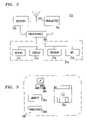
- FIG. 1is an illustrative representation of a telecommunication system, which includes a wireless communication system, utilizing a computer test station;
- FIG. 2is a schematic block diagram of a wireless telephone unit in the wireless communication system of FIG. 1 ;
- FIG. 3is an illustration of various software components which may be utilized in connection with the methods executed at the computer test station;
- FIG. 4is an illustrative representation of the selections involved in connecting a telephone call between the computer test station and a wireless telephone unit;
- FIG. 5is a flowchart describing a method for use in accessing the computer test station
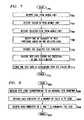
- FIG. 6is an illustrative representation of a plurality of test functions available at the computer test station
- FIG. 7is a flowchart describing a method for use in testing within the telecommunication system
- FIG. 8is a flowchart describing a method of setting up a test function, namely an answered call test, for execution by the computer test station;
- FIG. 9is a flowchart describing a method of executing the test function which was setup as described in relation to FIG. 8 ;
- FIG. 10is an illustrative representation of a visual presentation of test data from the execution of the test function as described in relation to FIG. 9 ;
- FIG. 11is a flowchart describing a method of executing a test function, namely a dropped call test.
- FIG. 12is a flowchart describing a method of executing a troubleshooting function which provides call tracing for problematic telephone calls.
- FIG. 1is a block diagram of a telecommunication system 100 .
- Telecommunication system 100includes a public switched telephone network (PSTN) 108 and a wireless communication system 102 .
- wireless communication system 102is a cellular telephone system having a plurality of mobile telephone switching offices (MTSO), such as an MTSO 106 , and a plurality of base stations coupled to the MTSOs, such as base stations 112 , 114 , and 116 coupled to MTSO 106 .
- a plurality of wireless telephone units 104are served by the plurality of base stations 102 in wireless communication system 102 , such as wireless telephone units 118 and 120 being served by base station 114 .
- the MTSOsoperate and select from a plurality of devices 134 , which is described in more detail below.
- a computer test station 110is coupled to telecommunication system 100 and is located remotely from the plurality of wireless telephone units 104 .
- Computer test station 110includes a computer 124 , a computer telephony card 126 , a central processing unit (CPU) or computer processor 128 , a memory 130 , a software application 122 , and a database 132 .
- Application 122includes wireless telephone communication test software which is executed by computer processor 128 .
- Application 122is executable to perform test functions, test setup functions, and to control computer telephony card 126 , as described in more detail below. Referring ahead to FIG. 3 , the methods described herein may be embodied and implemented more generally in connection with software using software components 300 shown in FIG. 3 .
- the softwaremay be embedded in or stored on a disk 302 or memory 304 , executable on a computer 306 or a processor 308 .
- inventive featuresmay exist in a signal-bearing medium which embodies a program of machine-readable instructions executable by a processing apparatus which perform the methods.
- computer telephony card 126has a telephone line interface for coupling to a plurality of land lines (e.g., four land line interfaces associated with four different telephone numbers).
- Computer telephony card 126is used for telephonic functions, encode and decode, and line selection.
- Computer telephony card 126preferably embodies a voice response unit (VRU) for accessing and selecting functions of computer test station 110 .
- VRUvoice response unit
- a suitable computer telephony card 126may be provided by DialogicTM of Parsippany, N.J., U.S.A.
- FIG. 2is a schematic block diagram of wireless telephone unit 118 of wireless communication system 102 of FIG. 1 .
- Wireless telephone unit 118 of FIG. 2may be representative of each wireless telephone unit utilized in wireless communication system 102 of FIG. 1 .
- Wireless telephone unit 118has an antenna 202 , a wireless receiver 204 and a wireless transmitter 206 coupled to antenna 202 , one or more processors 208 which control reception and transmission, and a user interface 210 also controlled by one or more processors 208 .
- User interface 210 of wireless telephone unit 118may include one or more of a keypad 212 , a visual display 214 , a speaker 216 , and a microphone 218 .
- Keypad 212may include a dual-tone multiple frequency (DTMF) keypad.
- DTMFdual-tone multiple frequency
- Visual display 214is utilized for confirmation of user-selected information and for the display of messages and visual presentations.
- Speaker 216 and microphone 218are utilized for listening and speaking, respectively, in telephonic communications.
- Wireless telephone unit 118may be a cellular telephone which has a unique Mobile Identification Number (MIN) or caller identification (ID) number associated therewith.
- MINMobile Identification Number
- IDcaller identification
- FIG. 4is an illustrative representation related to the use of an abbreviated dialing telephone number, such as “#TEST” (or #8378), for use by multiple wireless telephone units in accessing computer test station 110 of FIG. 1 .
- “Abbreviated Dialing” and the use of abbreviated dialing telephone numbersare well-known, but not in connection with computer test station 110 for testing wireless communications as described herein.
- wireless telephone unit 118initially dials #TEST in an attempt to access computer test station 110 .
- the telephone connection request with #TESTis received at MTSO 106 .
- MTSO 106substitutes #TEST with a telephone number (via a lookup table) and transfers the request to PSTN 108 .
- PSTN 108receives this telephone number and selects an available number (i.e., one that is not in use) from a plurality of telephone numbers of a “hunt group” associated therewith. Each one of the plurality of telephone numbers of the hunt group is associated with a corresponding land line coupled to computer telephony card 126 .
- a wireless telephone unitdials in, a new instance of the test application is utilized.
- multiple wireless telephone unitsare being served by computer test station 110 simultaneously, multiple instances of the test software are running.
- multiple wireless telephone unitsmay access computer test station 110 at the same or different times, and select from a number of different functions.
- computer test station 110is associated with an easy-to-remember access number and multiple wireless units can use computer test station 110 simultaneously. Another result, somewhat unexpected, is that only wireless telephone units having service associated with MTSO 106 are allowed access to computer test station 110 ; others cannot gain access.
- test station 110 of FIG. 1is equipped to execute a plurality of tests or test functions 606 , such as a test function 608 , a test function 610 , a test function 612 , and a test function 614 .
- Test function 608may be, for example, an answered call test as described later in relation to FIGS. 8–10
- test function 610may be, for example, a dropped call test as described later in relation to FIG. 11 .
- Computer test station 110 of FIG. 1may receive test code data 602 in the form of DTMF signals which are selected at wireless telephone unit 118 (via its user interface).
- a decoder 604is utilized to detect one of a plurality of different test codes which uniquely corresponds to one of the plurality of test functions 606 .
- decoder 604is part of the VRU utilized at computer test station 110 .
- computer test station 110provides voice prompting for the wireless telephone units for system access and test selection.
- the selected test functionis executed by computer test station 110 sometime after its selection by wireless telephone unit 118 .
- FIG. 5is a flowchart describing a method for use in accessing computer test station 110 .
- computer test station 110receives a telephone call from wireless telephone unit 118 when a user of wireless telephone unit 118 dials “#TEST” (step 502 ). Being able to handle simultaneous telephone calls and tests, computer test station 110 selects one of a plurality of telephone lines for the telephone call (step 504 ) and executes an (additional) instance of the test application program (step 506 ).
- computer test station 110receives caller ID information from wireless telephone unit 118 (step 508 ).
- Computer test station 110prompts wireless telephone unit 118 to enter a personal identification number (PIN). The user of wireless telephone unit 118 enters the PIN (for example, via DTMF keypad) and computer test station 110 receives this data (step 510 ).
- PINpersonal identification number
- each number of a plurality of caller ID numbersis stored in association with a unique prestored PIN.
- Computer test station 110compares the received PIN with a PIN stored in association with a matching prestored caller ID number (step 512 ).
- Computer test station 110grants or denies access to functions of computer test station 110 based on the comparison (step 514 ). More particularly, if computer test station 110 does not find a matching caller ID number, then access is denied. If computer test station 110 finds a matching caller ID number, but the received PIN does not match the prestored PIN stored in association with the prestored caller ID number, then access is denied. If computer test station 110 finds a matching caller ID number, and the received PIN matches the prestored PIN, then access is granted.
- the flowchartends at a finish block 516 .
- computer test station 110compares the caller ID information with prestored caller ID numbers in database 132 and grants or denies access to functions of computer test station 110 based on the comparison (step 514 ). More particularly, if the caller ID information received matches one of the caller ID numbers prestored in database 132 then access is granted; otherwise access is denied. Thus, a simple preestablished relationship may provide access to computer test station 110 . In this embodiment, no prompting for any user information (e.g., PIN) is necessary.
- PINuser information
- steps 510 and 512are performed for wireless telephone unit 118 only during its initial telephone call to computer test station 110 .
- computer test station 110stores a positive data indication in association with the prestored caller ID number for wireless telephone unit 118 and grants access.
- computer test station 110grants access if the received caller ID matches the prestored caller ID, without any prompt for entry of a PIN.
- the methods described in relation to FIG. 5may be embodied in applications different from computer test stations.
- the methods describedmay be embodied in a computer processor of an otherwise conventional answering machine.
- the methodsmay be embodied in a computer processor of an otherwise conventional home appliance automation system.
- multiple unique caller IDs(as well as prestored PINs) may be stored for granting access to multiple members of a household having multiple cellular telephones.
- multiple conventional functionsmay be executed after access is granted using the methods described.
- FIG. 7is a flowchart describing a testing method for use in the telecommunication system of FIG. 1 .
- computer test station 110receives a call from wireless telephone unit 118 (step 702 ).
- computer test station 110receives caller ID information from wireless telephone unit 118 (step 704 ).
- computer test station 110has a plurality of different test functions, each one of which is associated with a particular test identification code.
- computer test station 110receives and detects one of the plurality of test identification codes (step 706 ).
- computer test station 110selects one of the plurality of test functions based on the test identification code (step 708 ).
- computer test station 110executes the test function associated with the test identification code (step 710 ).
- the execution of the test functiontypically involves calls between computer test station 110 and wireless telephone unit 118 , where computer test station 110 receives and monitors events and/or conditions of the test.
- computer test station 110receives test data during the execution of the test function (step 712 ).
- the testmay be relatively brief, or span over a long period of time.
- Computer test station 110may perform analysis and computations on the test data it receives.
- computer test station 110stores the test data, events and/or conditions, in association with the caller identification information previously received (step 714 ).
- the flowchartends at a finish block 716 , but the method described may repeat for a plurality of different wireless telephone units and different test functions.
- a number of different test data for a number of different wireless telephone unitsmay be identified and organized appropriately at computer test station 110 .
- computer test station 110is operative to simultaneously execute the same or different tests for different wireless telephone units. This may be particularly useful where wireless telephone units 118 and 120 are being simultaneously tested with the same test and in the same test environment (e.g., both in the same moving vehicle).
- a DTMF audio signal corresponding to telephone digit “5”may be selected at wireless telephone unit 118 and received and detected at computer test station 110 .
- Telephone digit “5”may uniquely correspond to a test function referred to as an autodial test or an answered call test.
- One implementation of the answered call testis described in relation to FIGS. 8 and 9 .
- FIG. 8is a flowchart describing a method for configuring one particular test function for execution, namely an answered call test.
- computer test station 110receives and detects a test identification code corresponding to the answered call test (step 802 ). This is one example of what may occur during steps 706 and 708 of FIG. 7 .
- computer test station 110prompts (via the VRU) wireless telephone unit 118 to select test parameters for the answered call test. For example, computer test station 110 prompts wireless telephone unit 118 to select a number of calls N to send.
- the end-user of wireless telephone unit 118selects this information via the user interface and computer test station 110 receives data indicative of the number of calls N to send (step 804 ).
- computer test station 110prompts wireless telephone unit 118 to select a time T (e.g., date and time, or expiration of time after hangup) to commence the testing.
- a time Te.g., date and time, or expiration of time after hangup
- the end-user of wireless telephone unit 118selects this information via the user interface and computer test station 110 receives data indicative of the time T to commence the test (step 806 ).
- the call between computer test station 110 and wireless telephone unit 118is then terminated, and the flowchart ends at a finish block 808 .
- the answered call testdescribed in relation to FIG. 9 , will commence at the selected time T.
- FIG. 9is a flowchart describing a method of testing a wireless telephone unit using the answered call test.
- computer test station 110monitors the time and determines, at step 902 , whether it is time to execute the answered call test. When it is time T, computer test station 110 executes the test function as will be described in connection with the subsequent steps.
- Computer test station 110attempts to place a call to wireless telephone unit 118 using the caller identification information previously received and stored (step 904 ). If wireless telephone unit 118 is able to detect the call page from base station 114 , it is able to answer the call; otherwise, it is not able to answer the call.
- step 906If computer test station 110 detects that wireless telephone unit 118 is available to answer (step 906 ), then it tallies the call as answered (e.g., increments a counter corresponding to a number of answered calls) (step 908 ). The call between computer test station 110 and wireless telephone unit 118 is then terminated (step 910 ). If computer test station 110 detects that wireless telephone unit 118 is not available to answer at step 906 , then it tallies the call as not answered (e.g., increments a counter corresponding to a number of unanswered calls) (step 909 ).
- computer test station 110determines if the number of placed test calls is equal to the number of calls N previously selected (step 912 ). If not, steps 904 through 912 are repeated as shown. If so, the test is mostly completed.
- Computer test station 110generates any further information (step 914 ) and stores all of the test information from the test in association with the caller ID information previously received (step 916 ).
- the further information generated in step 914could be, for example, based on an analysis of all of the test data and/or proper format for presentation or data input. The analysis could include, for example, calculations of percentages, comparisons with other test data from the same or different wireless telephone units, etc.
- the methodends at a finish block 918 , but may repeat for the same or different wireless telephone units. Since computer test station 110 is equipped to simultaneously handle multiple wireless telephone unit tests, this particular method described may be employed simultaneously for multiple wireless telephone unit tests.
- FIG. 10is an illustrative representation of a presentation 1000 from computer test station 110 which shows test data 1002 for multiple wireless telephone units with respect to the answered call test.
- the first column of datarecites the name of the particular data field, and each remaining column provides test data associated with a particular wireless telephone unit.
- test data 1002may include test time/date data 1004 , caller ID or MIN data 1006 , total calls attempted data 1008 , total calls failed data 101 , and specific data 1012 regarding the time and success/failure indication.
- Other useful datais stored and viewable as shown in FIG. 10 .
- test datais stored in proper association with caller ID/MIN information of each wireless telephone unit.
- Other datamay include, for example, data that identifies where the wireless telephone unit was located for each attempted call.
- FIG. 11is a flowchart describing a method of testing a wireless telephone unit using a test referred to as a “dropped call test,” which may also be utilized as an audio quality test.
- This testmay be invoked similarly to that described in relation to FIGS. 8 and 9 , that is, by selectively preprogramning the execution of the test function at a particular time or time delay, and using user-selected parameters.
- computer test station 110sends audio test signals, such as a predetermined speech sample, to wireless telephone unit 118 .
- audio test signalsmay be, for example, male and female voice signals provided by the Telecommunications Industry Association (TIA).
- computer test station 110detects whether the call has been dropped (step 1104 ). If the call has not been dropped at step 1104 , computer test station 110 determines whether a preselected time period has expired (step 1110 ). Preferably, the preselected time period is one which was preselected by wireless telephone unit 118 during a previous communication (e.g., similar to that described in relation to FIG. 8 ). If the time has not expired at step 1110 , then computer test station 110 continues monitoring these events back at step 1104 . If it is detected that the call has been dropped at step 1104 , computer test station 110 tallies it as a dropped call (e.g., by incrementing a counter) (step 1106 ).
- a preselected time periodis one which was preselected by wireless telephone unit 118 during a previous communication (e.g., similar to that described in relation to FIG. 8 ). If the time has not expired at step 1110 , then computer test station 110 continues monitoring these events back at step 1104 . If it is detected that the call
- computer test station 110automatically calls back wireless telephone unit 118 using the caller ID information (step 1108 ). If the time has expired at step 1110 , computer test station 110 records the information regarding the total test time and the number of calls dropped over that time period (step 1112 ). The method ends at a finish block 1114 , but may repeat for subsequent tests. Other data stored may include, for example, data that identifies where the wireless telephone unit was geographically located for each dropped call.
- FIG. 12is a flowchart describing a method for use in troubleshooting in a telecommunication system.
- a telephone call from a wireless telephone unitis received at the computer test station 110 (step 1202 ).
- the wireless telephone unitplaces this telephone call while it is simultaneously connected in a problematic telephone call.
- computer test station 110operates in a mode to identify the set of functionally different devices utilized in the problematic call.
- the wireless telephone unitis enabled for a three-way calling feature which is well-known in the art.
- the problematic telephone callcould be due to, for example, one of many conventional devices utilized in the call that is not operating properly.
- the problematic devicemay be an “echo canceller” that is not operating properly.
- MTSO 106utilizes a plurality of devices 134 for the connection of telephone calls, as do other MTSOs. As shown in FIG. 1 , each row of the plurality of devices 134 corresponds to devices that are functionally different, while each column shown corresponds to devices that are functionally the same. For each call established, a different set of functionally different devices are selected and utilized.
- column 1 (“A” devices)may correspond to a plurality of echo canceller devices (one of which is utilized in a connected call)
- column 2 (“B” devices)may correspond to a plurality of base station radio devices (one of which is utilized in a connected call)
- column 3 (“C” devices)may correspond to a plurality of PSTN route devices (one of which is utilized in a connected call), etc.
- caller ID informationis sent from the wireless telephone unit and received at computer test station 110 (step 1204 ).
- a user of the wireless telephone unitenters information (for example, DTMF signals) to identify the switch utilized in the problematic call, and computer test station 110 receives this data (step 1206 ).
- computer test station 110records and stores audio signals of the problematic call in a file (e.g., a “.wav” file) (step 1208 ).
- Computer test station 110sends a call trace request through the network using the switch identification information and the caller ID information (step 1210 ). More specifically, computer test station 110 automatically looks up in a table an IP address associated with the switch, connects to the switch using the IP address, logs in, and issues a trace command with the mobile number.
- the networkresponds to the trace command by sending computer test station 110 call trace information that includes an identification of a plurality of devices utilized in the problematic call (step 1212 ).
- computer test station 110sends a message having at least some of the call trace information and the audio file to a predetermined address (step 1214 ).
- computer test station 110may parse out only that information necessary. Text information of the message may indicate that a problem has been encountered (for example, “PLEASE CHECK OR REPLACE THE ECHO CANCELLER IDENTIFIED IN THIS CALL”).
- the messagemay be sent to wireless telephone unit 118 , to some computer device to initiate repairs (e.g., a system maintenance computer), or both.
- the messagemay be, for example, an electronic mail (e-mail) message where the audio file is sent as an attachment or enclosure. If a message is sent to wireless telephone unit 118 , computer test station 110 uses the caller ID information as the email address of wireless telephone unit 118 . The method ends at a finish block 1216 , but may repeat for subsequent calls and requests.
- e-mailelectronic mail
- an echo canceller devicemay be found at number 15 or “MECHO,” where the particular echo canceller device utilized in the call is identified by the number “2183.”
- a base station radio devicemay be found at number 14 or “MDVC,” where the particular base station radio device utilized in the call is identified by the number “3119.”
- a PSTN route devicemay be found at numbers 18, 19, and 24 or “IDX MUP” and “LINK” where the particular PSTN route device utilized in the call may be identified by the associated alphanumeric information.
Landscapes
- Physics & Mathematics (AREA)
- Electromagnetism (AREA)
- Engineering & Computer Science (AREA)
- Computer Networks & Wireless Communication (AREA)
- Signal Processing (AREA)
- Mobile Radio Communication Systems (AREA)
Abstract
Description
| The call trace information received in step 1212 may read as follows: |
| ======================================================== |
| Trace Captured Date & Time: | 11/09/1999 11:36:11 AM |
| Switch: | BOYNTON |
| Mobile Number: | 5613461655 |
| WO | PBIT2*195005*14729A51H | AT-32 | TIME 991109 1138 PA |
| <CTRAI:SNB=5613461655; | |
| CALL PATH TRACING | |
| XSS TRACING |
| IDX | SWDEV | DEV | DEVIDX | FID |
| 1 | MTA-1930 | 2 | 3 | H′03AC | 001C | ||
| 4 | |||||||
| 2 | CHCDR-2095 | 5 | 1 | H′03AC | 001C | ||
| 3 | MSCHC-2363 | 1 | 7 | H′03AC | 001C | ||
| 8 | |||||||
| 4 | MSSH-695 | 1 | 9 | H′03AC | 001C | ||
| 10 | 11 | ||||||
| 5 | CLCOF-2015 | 2 | 12 | H′03AC | 001C | ||
| 13 | |||||||
| 6 | CHVIEW-1-764 | ||||||
| 7 | MCHC-645 | 3 | 14 | H′03AC | 001C | ||
| 8 | MPOOL-4069 | 3 | 15 | H′03AC | 001C | ||
| 9 | MSEVR-35640 | 4 | 16 | H′03AC | 001C | ||
| 10 | MAUTH-37897 | 4 | H′03AC | 001C | |||
| 11 | MFRAUD-695 | 4 | H′03AC | 001C | |||
| 12 | UPAPOTB-6597 | 5 | 17 | H′03AC | 001C | ||
| 13 | SUPIA-1208 | 5 | H′03AC | 001C | |||
| 14 | MDVC-3119 | 7 | 18 | H′03AC | 001C | ||
| 15 | MECHO-2183 | 8 | 19 | H′03AC | 001C | ||
| 16 | MAUTHD-2000 | 9 | H′03AC | 001C | |||
| 17 | UPPCB-6597 | 20 | 12 | H′0000 | 0001 | ||
| 21 | |||||||
| 18 | MBTRAC-4995 | 14 | H′03AC | 001C | |||
| 19 | MECHO-2207 | 15 | H′03AC | 001C | |||
| 20 | UPAMHRB-6597 | 17 | 22 | H′0000 | 0001 | ||
| 21 | UPAMHSB-6597 | 17 | H′0000 | 0001 | |||
| 22 | UPLTD-2504 | 23 | 20 | H′0000 | 0001 | ||
| 23 | UPDC-2504 | 24 | 22 | H′0000 | 0001 | ||
| 24 | UPD24A-2504 | 23 | H′0000 | 0001 |
| SWITCH CONNECTED DEVICE |
| IDX | MUP | LINK | MUP | |
| 18 | GS-30-451 | GS-030027-241 | ||
| 19 | GS-27-167 | GS-027031-500 | ||
| 24 | GS-31-208 | GS-031027-244 |
| TAG | IDX | MISCDATA | |
| 36 | 9 | 5613461655 | |
| 41 | 9 | 5613461655 |
| AM TRAFFIC LEVEL TRACING |
| IDX | SWDEV | DEV | DEVIDX | FID | ||
| 1 | CHVIEW-1-764 | H′03AC | 001C | |||
| 2 | CHCDR-2095 | |||||
| END | ||||||
| < |
| ======================================================== |
| @ |
Claims (36)
Priority Applications (4)
| Application Number | Priority Date | Filing Date | Title |
|---|---|---|---|
| US09/724,577US7016672B1 (en) | 2000-11-28 | 2000-11-28 | Testing methods and apparatus for wireless communications |
| US11/330,489US7546121B2 (en) | 2000-11-28 | 2006-01-12 | Testing methods and apparatus for wireless communications |
| US11/330,486US7330724B2 (en) | 2000-11-28 | 2006-01-12 | Testing methods and apparatus for wireless communications |
| US11/330,482US7346346B2 (en) | 2000-11-28 | 2006-01-12 | Testing methods and apparatus for wireless communications |
Applications Claiming Priority (1)
| Application Number | Priority Date | Filing Date | Title |
|---|---|---|---|
| US09/724,577US7016672B1 (en) | 2000-11-28 | 2000-11-28 | Testing methods and apparatus for wireless communications |
Related Child Applications (3)
| Application Number | Title | Priority Date | Filing Date |
|---|---|---|---|
| US11/330,489DivisionUS7546121B2 (en) | 2000-11-28 | 2006-01-12 | Testing methods and apparatus for wireless communications |
| US11/330,486DivisionUS7330724B2 (en) | 2000-11-28 | 2006-01-12 | Testing methods and apparatus for wireless communications |
| US11/330,482DivisionUS7346346B2 (en) | 2000-11-28 | 2006-01-12 | Testing methods and apparatus for wireless communications |
Publications (1)
| Publication Number | Publication Date |
|---|---|
| US7016672B1true US7016672B1 (en) | 2006-03-21 |
Family
ID=36045671
Family Applications (4)
| Application Number | Title | Priority Date | Filing Date |
|---|---|---|---|
| US09/724,577Expired - Fee RelatedUS7016672B1 (en) | 2000-11-28 | 2000-11-28 | Testing methods and apparatus for wireless communications |
| US11/330,489Expired - Fee RelatedUS7546121B2 (en) | 2000-11-28 | 2006-01-12 | Testing methods and apparatus for wireless communications |
| US11/330,482Expired - Fee RelatedUS7346346B2 (en) | 2000-11-28 | 2006-01-12 | Testing methods and apparatus for wireless communications |
| US11/330,486Expired - Fee RelatedUS7330724B2 (en) | 2000-11-28 | 2006-01-12 | Testing methods and apparatus for wireless communications |
Family Applications After (3)
| Application Number | Title | Priority Date | Filing Date |
|---|---|---|---|
| US11/330,489Expired - Fee RelatedUS7546121B2 (en) | 2000-11-28 | 2006-01-12 | Testing methods and apparatus for wireless communications |
| US11/330,482Expired - Fee RelatedUS7346346B2 (en) | 2000-11-28 | 2006-01-12 | Testing methods and apparatus for wireless communications |
| US11/330,486Expired - Fee RelatedUS7330724B2 (en) | 2000-11-28 | 2006-01-12 | Testing methods and apparatus for wireless communications |
Country Status (1)
| Country | Link |
|---|---|
| US (4) | US7016672B1 (en) |
Cited By (15)
| Publication number | Priority date | Publication date | Assignee | Title |
|---|---|---|---|---|
| US20030208542A1 (en)* | 2002-05-01 | 2003-11-06 | Testquest, Inc. | Software test agents |
| US20040249954A1 (en)* | 2003-06-04 | 2004-12-09 | Yigang Cai | Call control component collection of communication device identification information for internet protocol endpoint |
| US20050059354A1 (en)* | 2003-09-16 | 2005-03-17 | Wen Zhao | Method for conducting radiated performance tests of a wireless device |
| US20050144530A1 (en)* | 2002-05-01 | 2005-06-30 | Testquest, Inc. | Method and apparatus for making and using wireless test verbs |
| US20060046751A1 (en)* | 2004-08-26 | 2006-03-02 | Tommy Le | Status request messages for use on a mobile handset |
| US20060100841A1 (en)* | 2004-09-02 | 2006-05-11 | Tung-Ho Wu | Automatic system and method for testing mobile phone |
| US20060105762A1 (en)* | 2000-11-28 | 2006-05-18 | Cingular Wireless Ii, Llc | Testing methods and apparatus for wireless communications |
| US20060270398A1 (en)* | 2004-03-05 | 2006-11-30 | Anritsu Corporation | Communication terminal performance measurement system having effective trace information display function and communication terminal performance measurement method |
| US20070174868A1 (en)* | 2006-01-26 | 2007-07-26 | Kabushiki Kaisha Toshiba | Apparatus for personal authentication |
| EP2012467A1 (en)* | 2007-07-04 | 2009-01-07 | Nec Corporation | Network apparatus test system and network apparatus test method |
| US20100229226A1 (en)* | 2009-03-06 | 2010-09-09 | At&T Intellectual Property I, L.P. | Function-Based Authorization to Access Electronic Devices |
| TWI386021B (en)* | 2007-08-07 | 2013-02-11 | Chunghwa Telecom Co Ltd | Dispersed call tracking screens with versatile characters and reliability Methods and systems |
| US20150163348A1 (en)* | 2013-12-05 | 2015-06-11 | Genband Us Llc | Debug Line Tracer |
| US9619370B1 (en)* | 2006-02-08 | 2017-04-11 | Federeal Home Loan Mortgage Corporation (Freddie Mac) | Systems and methods for infrastructure validation |
| US20240171677A1 (en)* | 2007-02-15 | 2024-05-23 | Dsi-Iti, Llc | System and method for three-way call detection |
Families Citing this family (34)
| Publication number | Priority date | Publication date | Assignee | Title |
|---|---|---|---|---|
| US7146524B2 (en)* | 2001-08-03 | 2006-12-05 | Isilon Systems, Inc. | Systems and methods for providing a distributed file system incorporating a virtual hot spare |
| JP2006060762A (en)* | 2004-07-21 | 2006-03-02 | Hitachi Communication Technologies Ltd | Wireless communication system, diagnostic method thereof, and wireless terminal used for diagnosis of wireless communication system |
| US8051425B2 (en)* | 2004-10-29 | 2011-11-01 | Emc Corporation | Distributed system with asynchronous execution systems and methods |
| US8055711B2 (en)* | 2004-10-29 | 2011-11-08 | Emc Corporation | Non-blocking commit protocol systems and methods |
| GB2421401A (en)* | 2004-12-15 | 2006-06-21 | Agilent Technologies Inc | Test instrument for testing a wireless device |
| US7788303B2 (en) | 2005-10-21 | 2010-08-31 | Isilon Systems, Inc. | Systems and methods for distributed system scanning |
| US7917474B2 (en)* | 2005-10-21 | 2011-03-29 | Isilon Systems, Inc. | Systems and methods for accessing and updating distributed data |
| US7551572B2 (en)* | 2005-10-21 | 2009-06-23 | Isilon Systems, Inc. | Systems and methods for providing variable protection |
| US20070178881A1 (en)* | 2006-01-31 | 2007-08-02 | Teunissen Harold W A | Remotely controlling access to subscriber data over a wireless network for a mobile device |
| US7848261B2 (en)* | 2006-02-17 | 2010-12-07 | Isilon Systems, Inc. | Systems and methods for providing a quiescing protocol |
| US7610529B2 (en)* | 2006-04-28 | 2009-10-27 | Research In Motion Limited | Testing mobile wireless devices during device production |
| DE102006038152B4 (en)* | 2006-08-16 | 2014-08-28 | Semikron Elektronik Gmbh & Co. Kg | Circuit for drivers and systems of power electronics |
| US7680842B2 (en)* | 2006-08-18 | 2010-03-16 | Isilon Systems, Inc. | Systems and methods for a snapshot of data |
| US7822932B2 (en)* | 2006-08-18 | 2010-10-26 | Isilon Systems, Inc. | Systems and methods for providing nonlinear journaling |
| US7590652B2 (en)* | 2006-08-18 | 2009-09-15 | Isilon Systems, Inc. | Systems and methods of reverse lookup |
| US7899800B2 (en)* | 2006-08-18 | 2011-03-01 | Isilon Systems, Inc. | Systems and methods for providing nonlinear journaling |
| US7953704B2 (en)* | 2006-08-18 | 2011-05-31 | Emc Corporation | Systems and methods for a snapshot of data |
| US7680836B2 (en)* | 2006-08-18 | 2010-03-16 | Isilon Systems, Inc. | Systems and methods for a snapshot of data |
| US8286029B2 (en) | 2006-12-21 | 2012-10-09 | Emc Corporation | Systems and methods for managing unavailable storage devices |
| US7593938B2 (en)* | 2006-12-22 | 2009-09-22 | Isilon Systems, Inc. | Systems and methods of directory entry encodings |
| US7779048B2 (en) | 2007-04-13 | 2010-08-17 | Isilon Systems, Inc. | Systems and methods of providing possible value ranges |
| US7900015B2 (en)* | 2007-04-13 | 2011-03-01 | Isilon Systems, Inc. | Systems and methods of quota accounting |
| US7966289B2 (en) | 2007-08-21 | 2011-06-21 | Emc Corporation | Systems and methods for reading objects in a file system |
| US7882068B2 (en)* | 2007-08-21 | 2011-02-01 | Isilon Systems, Inc. | Systems and methods for adaptive copy on write |
| US7949692B2 (en)* | 2007-08-21 | 2011-05-24 | Emc Corporation | Systems and methods for portals into snapshot data |
| US7984324B2 (en)* | 2008-03-27 | 2011-07-19 | Emc Corporation | Systems and methods for managing stalled storage devices |
| US7953709B2 (en)* | 2008-03-27 | 2011-05-31 | Emc Corporation | Systems and methods for a read only mode for a portion of a storage system |
| CN101316430A (en)* | 2008-06-27 | 2008-12-03 | 华为技术有限公司 | Communication information collection method, testing method and network side equipment |
| US8600371B2 (en) | 2009-10-18 | 2013-12-03 | Locus Location Systems Llc | Method and system for diagnosing radio performance during functional over-the-air operation |
| US8565096B2 (en)* | 2009-10-18 | 2013-10-22 | Locus Location Systems, Llc | Method and system for analyzing radio performance during over-the-air operation |
| EP2381666B1 (en)* | 2010-04-26 | 2012-10-03 | Research In Motion Limited | Method, system and apparatus for handling a call received at a mobile communication device |
| US20140222999A1 (en)* | 2011-02-15 | 2014-08-07 | Nokia Siemens Networks Oy | Method for the testing of service applications in a value added server of a communication network |
| JP2012208810A (en)* | 2011-03-30 | 2012-10-25 | Buffalo Inc | Authentication method, network apparatus, server device, mobile phone terminal, and information processing apparatus |
| US8825042B2 (en) | 2011-05-12 | 2014-09-02 | Lows Location Systems, LLC | Network diagnostic system for analyzing the performance of a radio network during functional over-the-air operation |
Citations (10)
| Publication number | Priority date | Publication date | Assignee | Title |
|---|---|---|---|---|
| US4977399A (en) | 1988-08-09 | 1990-12-11 | At&E Corporation | Mobile radio paging test system |
| US5023900A (en) | 1989-12-07 | 1991-06-11 | Tayloe Daniel R | Cellular radiotelephone diagnostic system |
| US5031204A (en) | 1990-02-13 | 1991-07-09 | Gte Mobile Communications Service Corporation | Interactive diagnostic system for cellular telephones |
| US5095500A (en) | 1989-12-07 | 1992-03-10 | Motorola, Inc. | Cellular radiotelephone diagnostic system |
| US5425076A (en) | 1992-06-30 | 1995-06-13 | Minnesota Mining And Manufacturing Company | Cellular communications test system |
| US5481588A (en)* | 1993-04-06 | 1996-01-02 | Alcatel N.V. | Test arrangements for radio telephone systems |
| US5703929A (en)* | 1994-04-29 | 1997-12-30 | Harris Corporation | Wireless-wireline communication selection mechanism resident in craftsperson's portable test and communications device |
| US5903626A (en) | 1997-10-21 | 1999-05-11 | Siemens Information And Communication Networks, Inc. | Diagnostic device for troubleshooting remote digital feature phones |
| US5956636A (en) | 1996-07-16 | 1999-09-21 | At&T Wireless Services Inc. | Method and system for automatic activation of a wireless device |
| US5974311A (en) | 1995-10-30 | 1999-10-26 | At&T Wireless Services Inc. | Method and apparatus for storing activation data in a cellular telephone |
Family Cites Families (7)
| Publication number | Priority date | Publication date | Assignee | Title |
|---|---|---|---|---|
| US5901284A (en)* | 1996-06-19 | 1999-05-04 | Bellsouth Corporation | Method and system for communication access restriction |
| US6236365B1 (en)* | 1996-09-09 | 2001-05-22 | Tracbeam, Llc | Location of a mobile station using a plurality of commercial wireless infrastructures |
| US6230006B1 (en)* | 1997-09-08 | 2001-05-08 | Acterna, Llc | Test system for remotely testing switches within a telecommunications network |
| US6625448B1 (en)* | 1999-11-02 | 2003-09-23 | Ericsson Inc. | Acoustic testing system and method for communications devices |
| US6751457B1 (en)* | 2000-06-28 | 2004-06-15 | Bellsouth Intellectual Property Corporation | Real time call monitoring system and method |
| US6771956B1 (en)* | 2000-11-08 | 2004-08-03 | Bellsouth Intellectual Property Corporation | Real time call data analysis and display |
| US7016672B1 (en)* | 2000-11-28 | 2006-03-21 | Cingular Wireless Ii, Llc | Testing methods and apparatus for wireless communications |
- 2000
- 2000-11-28USUS09/724,577patent/US7016672B1/ennot_activeExpired - Fee Related
- 2006
- 2006-01-12USUS11/330,489patent/US7546121B2/ennot_activeExpired - Fee Related
- 2006-01-12USUS11/330,482patent/US7346346B2/ennot_activeExpired - Fee Related
- 2006-01-12USUS11/330,486patent/US7330724B2/ennot_activeExpired - Fee Related
Patent Citations (10)
| Publication number | Priority date | Publication date | Assignee | Title |
|---|---|---|---|---|
| US4977399A (en) | 1988-08-09 | 1990-12-11 | At&E Corporation | Mobile radio paging test system |
| US5023900A (en) | 1989-12-07 | 1991-06-11 | Tayloe Daniel R | Cellular radiotelephone diagnostic system |
| US5095500A (en) | 1989-12-07 | 1992-03-10 | Motorola, Inc. | Cellular radiotelephone diagnostic system |
| US5031204A (en) | 1990-02-13 | 1991-07-09 | Gte Mobile Communications Service Corporation | Interactive diagnostic system for cellular telephones |
| US5425076A (en) | 1992-06-30 | 1995-06-13 | Minnesota Mining And Manufacturing Company | Cellular communications test system |
| US5481588A (en)* | 1993-04-06 | 1996-01-02 | Alcatel N.V. | Test arrangements for radio telephone systems |
| US5703929A (en)* | 1994-04-29 | 1997-12-30 | Harris Corporation | Wireless-wireline communication selection mechanism resident in craftsperson's portable test and communications device |
| US5974311A (en) | 1995-10-30 | 1999-10-26 | At&T Wireless Services Inc. | Method and apparatus for storing activation data in a cellular telephone |
| US5956636A (en) | 1996-07-16 | 1999-09-21 | At&T Wireless Services Inc. | Method and system for automatic activation of a wireless device |
| US5903626A (en) | 1997-10-21 | 1999-05-11 | Siemens Information And Communication Networks, Inc. | Diagnostic device for troubleshooting remote digital feature phones |
Non-Patent Citations (4)
| Title |
|---|
| Author unknown, "Hunt Groups" VoiceServer.net Operation, http://www.voiceserver.net/operation/hunt<SUB>-</SUB>groups.htm, date unknown, 1 pg. |
| Author unknown, "Local Service-Business Trunks" TXU Communications, http://www.lcc.net/business/local<SUB>-</SUB>telephone/trunks.htm, date unknown, 2 pgs. |
| Author unknown, "Telephone Interface Auto Coupler", http://www.gentner.com/t4paut.html, date unknown, 1 pg. |
| Author unknown, Lucent Technologies DEFINITY(R) G3si Telephone System Users Guide, Sep. 1998, 53 pgs. |
Cited By (27)
| Publication number | Priority date | Publication date | Assignee | Title |
|---|---|---|---|---|
| US20060105762A1 (en)* | 2000-11-28 | 2006-05-18 | Cingular Wireless Ii, Llc | Testing methods and apparatus for wireless communications |
| US7346346B2 (en)* | 2000-11-28 | 2008-03-18 | At&T Mobility Ii Llc | Testing methods and apparatus for wireless communications |
| US20030208542A1 (en)* | 2002-05-01 | 2003-11-06 | Testquest, Inc. | Software test agents |
| US20050144530A1 (en)* | 2002-05-01 | 2005-06-30 | Testquest, Inc. | Method and apparatus for making and using wireless test verbs |
| US7734027B2 (en)* | 2003-06-04 | 2010-06-08 | Alcatel-Lucent Usa Inc. | Call control component collection of communication device identification information for internet protocol endpoint |
| US20040249954A1 (en)* | 2003-06-04 | 2004-12-09 | Yigang Cai | Call control component collection of communication device identification information for internet protocol endpoint |
| US8340590B2 (en) | 2003-09-16 | 2012-12-25 | Research In Motion Limited | Method for conducting radiated performance tests of a wireless device |
| US20100004899A1 (en)* | 2003-09-16 | 2010-01-07 | Research In Motion Limited | Method For Conducting Radiated Performance Tests Of A Wireless Device |
| US7599687B2 (en) | 2003-09-16 | 2009-10-06 | Research In Motion Limited | Apparatus for conducting radiated performance tests of a wireless device |
| US20080214117A1 (en)* | 2003-09-16 | 2008-09-04 | Research In Motion Limited | Method for conducting radiated performance tests of a wireless device |
| US20050059354A1 (en)* | 2003-09-16 | 2005-03-17 | Wen Zhao | Method for conducting radiated performance tests of a wireless device |
| US7359701B2 (en)* | 2003-09-16 | 2008-04-15 | Research In Motion Limited | Method for conducting radiated performance tests of a wireless device |
| US20060270398A1 (en)* | 2004-03-05 | 2006-11-30 | Anritsu Corporation | Communication terminal performance measurement system having effective trace information display function and communication terminal performance measurement method |
| US7289802B2 (en)* | 2004-03-05 | 2007-10-30 | Anritsu Corporation | Communication terminal performance measurement system having effective trace information display function and communication terminal performance measurement method |
| US7471959B2 (en)* | 2004-08-26 | 2008-12-30 | Kyocera Wireless Corp. | Status request messages for use on a mobile handset |
| US20060046751A1 (en)* | 2004-08-26 | 2006-03-02 | Tommy Le | Status request messages for use on a mobile handset |
| US20060100841A1 (en)* | 2004-09-02 | 2006-05-11 | Tung-Ho Wu | Automatic system and method for testing mobile phone |
| US20070174868A1 (en)* | 2006-01-26 | 2007-07-26 | Kabushiki Kaisha Toshiba | Apparatus for personal authentication |
| US9619370B1 (en)* | 2006-02-08 | 2017-04-11 | Federeal Home Loan Mortgage Corporation (Freddie Mac) | Systems and methods for infrastructure validation |
| US10140205B1 (en) | 2006-02-08 | 2018-11-27 | Federal Home Loan Mortgage Corporation (Freddie Mac) | Systems and methods for infrastructure validation |
| US20240171677A1 (en)* | 2007-02-15 | 2024-05-23 | Dsi-Iti, Llc | System and method for three-way call detection |
| US20090013072A1 (en)* | 2007-07-04 | 2009-01-08 | Nec Corporation | Network apparatus test system and network apparatus test method |
| EP2012467A1 (en)* | 2007-07-04 | 2009-01-07 | Nec Corporation | Network apparatus test system and network apparatus test method |
| TWI386021B (en)* | 2007-08-07 | 2013-02-11 | Chunghwa Telecom Co Ltd | Dispersed call tracking screens with versatile characters and reliability Methods and systems |
| US8789160B2 (en) | 2009-03-06 | 2014-07-22 | At&T Intellectual Property I, L.P. | Function-based authorization to access electronic devices |
| US20100229226A1 (en)* | 2009-03-06 | 2010-09-09 | At&T Intellectual Property I, L.P. | Function-Based Authorization to Access Electronic Devices |
| US20150163348A1 (en)* | 2013-12-05 | 2015-06-11 | Genband Us Llc | Debug Line Tracer |
Also Published As
| Publication number | Publication date |
|---|---|
| US7346346B2 (en) | 2008-03-18 |
| US7546121B2 (en) | 2009-06-09 |
| US20060105747A1 (en) | 2006-05-18 |
| US7330724B2 (en) | 2008-02-12 |
| US20060105762A1 (en) | 2006-05-18 |
| US20060105763A1 (en) | 2006-05-18 |
Similar Documents
| Publication | Publication Date | Title |
|---|---|---|
| US7016672B1 (en) | Testing methods and apparatus for wireless communications | |
| US5485511A (en) | Method and apparatus for determining the telephony features assigned to a telephone | |
| CA2190045C (en) | Customer activation system for cellular network | |
| KR940000706B1 (en) | Dialing features for cellular telephone with standard telephone set | |
| US8126457B2 (en) | Method and system for provisioning services in a telecommunications network | |
| US5109403A (en) | System for programming of features of a mobile cellular telephone unit | |
| AU2002252902A1 (en) | Method and system for provisioning services in a telecommunications network | |
| CA2481203A1 (en) | Method and apparatus for measuring communication market statistics | |
| US6332073B1 (en) | Emergency number dialing from a fixed cellular terminal | |
| US20070121831A1 (en) | Apparatus and method for making call connection when parties try to sumultaneously call each other | |
| US7912462B2 (en) | Method for conducting digital interface and baseband circuitry tests using digital loopback | |
| RU2001132548A (en) | A malicious call processing method and a switching apparatus for implementing this method | |
| CN110493810B (en) | Method, device, equipment and medium for detecting recording notification fault | |
| CN100568897C (en) | Method for remotely associating a communication device with a computer terminal | |
| JP4377524B2 (en) | Wireless phone voicemail system access number automatic programming method | |
| CN113037525A (en) | Network fault diagnosis method and device, network equipment and computer readable medium | |
| JP3014460B2 (en) | Adaptive wireless subscriber station matching method in transmission network and corresponding wireless subscriber station | |
| AU751379B2 (en) | Method and apparatus for providing out of band dialed digit signaling for caller interface in a fixed cellular communications system | |
| US20060098595A1 (en) | Multiparty calling method and corresponding mobile communication terminal | |
| KR0161129B1 (en) | Password Acceptance Method using Password in Electronic Switching System | |
| CN109195155B (en) | Method, Apparatus, Device and Readable Storage Medium for Determining Dual-SIM Terminal User Identity | |
| KR100639855B1 (en) | Apparatus and method for transmitting caller ID data transmission test in electronic switching system | |
| US6480576B1 (en) | Method and device for detecting path faults in a network | |
| KR100584353B1 (en) | Call notification method using caller ID code | |
| CA2516204C (en) | Method for conducting digital interface and baseband circuitry tests using digital loopback |
Legal Events
| Date | Code | Title | Description |
|---|---|---|---|
| AS | Assignment | Owner name:AT&T WIRELESS SERVICES, INC., WASHINGTON Free format text:ASSIGNMENT OF ASSIGNORS INTEREST;ASSIGNOR:LIPSIT, JAMES;REEL/FRAME:012415/0825 Effective date:20010420 | |
| AS | Assignment | Owner name:CINGULAR WIRLEESS II, LLC, GEORGIA Free format text:CERTIFICATE OF CONVERSION;ASSIGNOR:CINGULAR WIRELESS II, INC.;REEL/FRAME:017546/0612 Effective date:20041027 Owner name:CINGULAR WIRLEESS II, LLC,GEORGIA Free format text:ASSIGNMENT OF ASSIGNORS INTEREST;ASSIGNOR:CINGULAR WIRELESS II, INC.;REEL/FRAME:017546/0612 Effective date:20041027 Owner name:CINGULAR WIRELESS II, INC.,GEORGIA Free format text:ASSIGNMENT OF ASSIGNORS INTEREST;ASSIGNOR:NEW CINGULAR WIRELESS SERVICES, INC. F/K/A AT&T WIRELESS SERVICES, INC.;REEL/FRAME:017555/0711 Effective date:20041027 Owner name:CINGULAR WIRELESS II, INC., GEORGIA Free format text:ASSIGNMENT OF ASSIGNORS INTEREST;ASSIGNOR:NEW CINGULAR WIRELESS SERVICES, INC. F/K/A AT&T WIRELESS SERVICES, INC.;REEL/FRAME:017555/0711 Effective date:20041027 Owner name:CINGULAR WIRLEESS II, LLC, GEORGIA Free format text:ASSIGNMENT OF ASSIGNORS INTEREST;ASSIGNOR:CINGULAR WIRELESS II, INC.;REEL/FRAME:017546/0612 Effective date:20041027 | |
| AS | Assignment | Owner name:CINGULAR WIRELESS II, LLC,GEORGIA Free format text:CERTIFICATE OF CONVERSION;ASSIGNOR:CINGULAR WIRELESS II, INC.;REEL/FRAME:017696/0375 Effective date:20041027 Owner name:CINGULAR WIRELESS II, LLC, GEORGIA Free format text:CERTIFICATE OF CONVERSION;ASSIGNOR:CINGULAR WIRELESS II, INC.;REEL/FRAME:017696/0375 Effective date:20041027 | |
| AS | Assignment | Owner name:AT&T MOBILITY II, LLC, GEORGIA Free format text:CHANGE OF NAME;ASSIGNOR:CINGULAR WIRELESS II, LLC;REEL/FRAME:021047/0800 Effective date:20070420 | |
| AS | Assignment | Owner name:AT&T MOBILITY II LLC, GEORGIA Free format text:CHANGE OF NAME;ASSIGNOR:AT&T MOBILITY II, LLC;REEL/FRAME:021114/0095 Effective date:20070830 | |
| FPAY | Fee payment | Year of fee payment:4 | |
| FPAY | Fee payment | Year of fee payment:8 | |
| FEPP | Fee payment procedure | Free format text:MAINTENANCE FEE REMINDER MAILED (ORIGINAL EVENT CODE: REM.) | |
| LAPS | Lapse for failure to pay maintenance fees | Free format text:PATENT EXPIRED FOR FAILURE TO PAY MAINTENANCE FEES (ORIGINAL EVENT CODE: EXP.) | |
| STCH | Information on status: patent discontinuation | Free format text:PATENT EXPIRED DUE TO NONPAYMENT OF MAINTENANCE FEES UNDER 37 CFR 1.362 | |
| FP | Lapsed due to failure to pay maintenance fee | Effective date:20180321 |