US7015826B1 - Method and apparatus for sensing and transmitting a body characteristic of a host - Google Patents
Method and apparatus for sensing and transmitting a body characteristic of a hostDownload PDFInfo
- Publication number
- US7015826B1 US7015826B1US10/114,875US11487502AUS7015826B1US 7015826 B1US7015826 B1US 7015826B1US 11487502 AUS11487502 AUS 11487502AUS 7015826 B1US7015826 B1US 7015826B1
- Authority
- US
- United States
- Prior art keywords
- temperature
- signal
- transponder
- identification
- analog
- Prior art date
- Legal status (The legal status is an assumption and is not a legal conclusion. Google has not performed a legal analysis and makes no representation as to the accuracy of the status listed.)
- Expired - Lifetime, expires
Links
Images


Classifications
- H—ELECTRICITY
- H04—ELECTRIC COMMUNICATION TECHNIQUE
- H04W—WIRELESS COMMUNICATION NETWORKS
- H04W84/00—Network topologies
- H04W84/18—Self-organising networks, e.g. ad-hoc networks or sensor networks
- A—HUMAN NECESSITIES
- A01—AGRICULTURE; FORESTRY; ANIMAL HUSBANDRY; HUNTING; TRAPPING; FISHING
- A01K—ANIMAL HUSBANDRY; AVICULTURE; APICULTURE; PISCICULTURE; FISHING; REARING OR BREEDING ANIMALS, NOT OTHERWISE PROVIDED FOR; NEW BREEDS OF ANIMALS
- A01K11/00—Marking of animals
- A01K11/006—Automatic identification systems for animals, e.g. electronic devices, transponders for animals
- A—HUMAN NECESSITIES
- A01—AGRICULTURE; FORESTRY; ANIMAL HUSBANDRY; HUNTING; TRAPPING; FISHING
- A01K—ANIMAL HUSBANDRY; AVICULTURE; APICULTURE; PISCICULTURE; FISHING; REARING OR BREEDING ANIMALS, NOT OTHERWISE PROVIDED FOR; NEW BREEDS OF ANIMALS
- A01K29/00—Other apparatus for animal husbandry
- G—PHYSICS
- G01—MEASURING; TESTING
- G01K—MEASURING TEMPERATURE; MEASURING QUANTITY OF HEAT; THERMALLY-SENSITIVE ELEMENTS NOT OTHERWISE PROVIDED FOR
- G01K1/00—Details of thermometers not specially adapted for particular types of thermometer
- G01K1/02—Means for indicating or recording specially adapted for thermometers
- G01K1/024—Means for indicating or recording specially adapted for thermometers for remote indication
- G—PHYSICS
- G01—MEASURING; TESTING
- G01K—MEASURING TEMPERATURE; MEASURING QUANTITY OF HEAT; THERMALLY-SENSITIVE ELEMENTS NOT OTHERWISE PROVIDED FOR
- G01K7/00—Measuring temperature based on the use of electric or magnetic elements directly sensitive to heat ; Power supply therefor, e.g. using thermoelectric elements
- G01K7/01—Measuring temperature based on the use of electric or magnetic elements directly sensitive to heat ; Power supply therefor, e.g. using thermoelectric elements using semiconducting elements having PN junctions
- G01K7/015—Measuring temperature based on the use of electric or magnetic elements directly sensitive to heat ; Power supply therefor, e.g. using thermoelectric elements using semiconducting elements having PN junctions using microstructures, e.g. made of silicon
- G—PHYSICS
- G06—COMPUTING OR CALCULATING; COUNTING
- G06K—GRAPHICAL DATA READING; PRESENTATION OF DATA; RECORD CARRIERS; HANDLING RECORD CARRIERS
- G06K19/00—Record carriers for use with machines and with at least a part designed to carry digital markings
- G06K19/06—Record carriers for use with machines and with at least a part designed to carry digital markings characterised by the kind of the digital marking, e.g. shape, nature, code
- G06K19/067—Record carriers with conductive marks, printed circuits or semiconductor circuit elements, e.g. credit or identity cards also with resonating or responding marks without active components
- G06K19/07—Record carriers with conductive marks, printed circuits or semiconductor circuit elements, e.g. credit or identity cards also with resonating or responding marks without active components with integrated circuit chips
- G06K19/0716—Record carriers with conductive marks, printed circuits or semiconductor circuit elements, e.g. credit or identity cards also with resonating or responding marks without active components with integrated circuit chips at least one of the integrated circuit chips comprising a sensor or an interface to a sensor
- G06K19/0717—Record carriers with conductive marks, printed circuits or semiconductor circuit elements, e.g. credit or identity cards also with resonating or responding marks without active components with integrated circuit chips at least one of the integrated circuit chips comprising a sensor or an interface to a sensor the sensor being capable of sensing environmental conditions such as temperature history or pressure
- G—PHYSICS
- G06—COMPUTING OR CALCULATING; COUNTING
- G06K—GRAPHICAL DATA READING; PRESENTATION OF DATA; RECORD CARRIERS; HANDLING RECORD CARRIERS
- G06K19/00—Record carriers for use with machines and with at least a part designed to carry digital markings
- G06K19/06—Record carriers for use with machines and with at least a part designed to carry digital markings characterised by the kind of the digital marking, e.g. shape, nature, code
- G06K19/067—Record carriers with conductive marks, printed circuits or semiconductor circuit elements, e.g. credit or identity cards also with resonating or responding marks without active components
- G06K19/07—Record carriers with conductive marks, printed circuits or semiconductor circuit elements, e.g. credit or identity cards also with resonating or responding marks without active components with integrated circuit chips
- G06K19/0723—Record carriers with conductive marks, printed circuits or semiconductor circuit elements, e.g. credit or identity cards also with resonating or responding marks without active components with integrated circuit chips the record carrier comprising an arrangement for non-contact communication, e.g. wireless communication circuits on transponder cards, non-contact smart cards or RFIDs
- H—ELECTRICITY
- H04—ELECTRIC COMMUNICATION TECHNIQUE
- H04Q—SELECTING
- H04Q9/00—Arrangements in telecontrol or telemetry systems for selectively calling a substation from a main station, in which substation desired apparatus is selected for applying a control signal thereto or for obtaining measured values therefrom
- H—ELECTRICITY
- H04—ELECTRIC COMMUNICATION TECHNIQUE
- H04Q—SELECTING
- H04Q2209/00—Arrangements in telecontrol or telemetry systems
- H04Q2209/40—Arrangements in telecontrol or telemetry systems using a wireless architecture
- H04Q2209/47—Arrangements in telecontrol or telemetry systems using a wireless architecture using RFID associated with sensors
- H—ELECTRICITY
- H04—ELECTRIC COMMUNICATION TECHNIQUE
- H04Q—SELECTING
- H04Q2209/00—Arrangements in telecontrol or telemetry systems
- H04Q2209/70—Arrangements in the main station, i.e. central controller
- H04Q2209/75—Arrangements in the main station, i.e. central controller by polling or interrogating the sub-stations
Definitions
- the inventionrelates generally to implantable radio frequency identification (RFID) systems and, more particularly, to an implantable transponder capable of transmitting identification information and body characteristic information of a host, including but not limited to a host animal.
- RFIDradio frequency identification
- Transponders and scanner systemsare well known in the art. These systems generally include a scanner, or interrogator, which transmits signals to, and receives signals from, one or more transponders.
- the transpondersmay be active, in that they contain a power source such as a battery, or passive in that they receive power from an external source, such as through inductive coupling as can be the case with radio frequency technology.
- Passive transpondersare commonly implanted in animals due to the fact that they do not rely on a self-contained power source. Such implantable, passive transponders often contain identification information for the animal. It is also known to have an implantable transponder coupled with a sensor, such as a temperature measurement device, such that the transponder is able to transmit both identification information, as well as information on the body characteristic of the animal.
- the temperature measurement devices used in conjunction with these transpondershave traditionally been thermistors.
- the resistance of the thermistorchanges as a function of the temperature of the thermistor.
- the transponderincludes a circuit which is connected to the thermistor and measures the resistance of the thermistor by supplying a known current, and measuring the voltage across the thermistor. The voltage is then measured and a temperature value derived from the voltage measurement correlated to the known resistance characteristics of the thermistor.
- an implantable transponderis a passive device, it is highly desirable to have the implantable transponder consume little power.
- traditional thermistor based temperature sensorsincrease power consumption by requiring a predetermined current be supplied to the thermistor. This additional current increases the power consumption of the transponder significantly. Accordingly, it would be advantageous to have an implantable transponder capable of transmitting temperature information, and which also consumes less power than thermistor transponders which are capable of transmitting temperature information.
- the manufacture and assembly of a temperature sensing transponderrequires additional resources compared to the manufacture and assembly of a typical identification transponder.
- Assembly of a temperature sensing transponderis generally done after the components comprising the identification subassembly of the transponder and the components comprising the temperature sensor or thermistor have been manufactured and/or assembled.
- the two manufactured subassemblies or componentsare then combined in a separate manufacturing step.
- This separate manufacturing stepcan take a significant amount of time and resources, ultimately increasing the cost of such a transponder.
- each thermistoris required to be calibrated, in order to ensure that an accurate temperature is delivered to a user.
- Such a calibrationis performed following the full assembly of the transponder.
- the assembled transponderis generally placed in a liquid bath having a known temperature.
- An initial temperature readingis determined using the transponder.
- This initial temperature readingis compared to the known temperature of the bath, and a compensation factor is determined for the transponder.
- This compensation factoris typically stored in a memory location within the transponder, and sent to the scanner together with the sensed temperature information requiring the scanner to perform a calculation to determine the temperature of the animal.
- transponders having associated temperature sensorstypically transmit identification information and temperature information in a unique transmission format.
- different manufacturersemploy unique communication schemes which require particular interrogators to be able to read their transponders.
- one manufacturer's transmission formatmay not be able to be read by scanners which were not specifically designed to read such information, i.e., a competitor's scanner.
- Thiscan be disadvantageous because, in the event that an animal having such a transponder becomes lost or stolen, the transponder can be used as a means of identification for the animal.
- a scanneris used to attempt to scan a transponder and does not recognize the unique format for its identification information, the scanner will be unable to determine the identification information which is stored in the transponder.
- it would also be advantageous to have a temperature sensing transponderwhich is able to transmit identification information in a format which is able to be read by most common scanners.
- the inventionprovides a temperature sensing transponder having a temperature sensor integrated with the transponder.
- the transponderreceives an interrogation signal from a scanner, and is operable to transmit identification information and calibrated temperature information to a scanner.
- the scanneris operable to receive the identification and calibrated temperature information and display and/or store the information.
- the temperature sensoris integrated into the transponder and determines the temperature of the transponder using the temperature dependent characteristics of the P-N junction.
- the temperature sensing transponderincludes an antenna portion operable to receive an interrogation signal from a reader and to transmit a data signal to the reader, the data signal including identification information and temperature information; and an integrated circuit having a memory portion containing an identifier uniquely associated with the transponder and an integrated temperature sensor portion, the integrated circuit operable to receive the interrogation signal from the antenna portion, and generate the data signal for transmission by the antenna portion.
- the integrated temperature sensor portionincludes a temperature sensor and is operable to generate an analog temperature signal which corresponds to a temperature of the temperature sensor. In one embodiment, the temperature sensor determines temperature based on the temperature dependent characteristics of the P-N junction.
- the temperature sensormay include first and second bipolar junction transistor portions, where the first and second bipolar junction transistor portions are operated at a substantially constant ratio of emitter current densities, and the analog temperature signal corresponds to a difference in base-emitter voltages between the first and second bipolar junction transistor portions.
- the integrated circuitmay include an analog to digital converter, the analog to digital converter being operable to receive the analog temperature signal and convert the analog temperature signal into a digital temperature code.
- the integrated temperature sensoris operable to read an analog trim value from the memory and adjust the analog temperature signal based on the analog trim value.
- the adjustment to the analog temperature signalmay be an offset to the analog temperature signal based on the analog trim value, or may be a gain adjustment to an amplification portion of the integrated temperature sensor.
- the integrated circuitmay also contain a serial adder operable to read a fine trim value from the memory and add the digital temperature code to the fine trim value to create the temperature information.
- the transpondermay include one or more sensors to detect characteristics of the body in which it is embedded other than termperature. The signal from these sensors may be adjusted in a similar manner for transmission by the transponder.
- the data signal transmitted from the transpondermay include at least one identification telegram containing the identification information and at least one temperature telegram containing the temperature information.
- the data signal transmitted from the transpondermay also include a single telegram containing both the identification information and the temperature information.
- the identification telegrammay be compatible with an FDXA transmission, and the single telegram may be compatible with an FDXB transmission.
- the integrated circuitincludes a selection circuit operable to select between a first and a second communication mode.
- the integrated circuitWhen the first communication mode is selected, the integrated circuit generates a first telegram for inclusion in the data signal containing identification information and a second telegram for inclusion in the data signal containing temperature information.
- the integrated circuitWhen the second communication mode is selected, the integrated circuit generates a single telegram for inclusion in the data signal containing identification and temperature information.
- the integrated circuitis operable to store history information in the memory, and transmit the history information in response to an interrogation.
- the history informationmay include additional identification information.
- the present inventionin one embodiment, also provides a method for calibrating a sensor in a transponder.
- the methodincludes the steps of measuring an analog signal from the sensor when the sensor is at a predetermined state, determining an analog trim value which is proportional to a difference between the analog signal and a predetermined signal, storing the analog trim value into a first memory location, adjusting the analog signal based on the analog trim value, creating a modified analog signal, reading a digital signal based on the modified analog signal, determining a fine trim value which is proportional to a difference between the digital signal and the predetermined digital signal, and storing the fine trim value into a second memory location.
- the measuring stepmay include reading a current from a sensor portion at an analog to digital converter; and converting said current to a digital value at the analog to digital converter.
- the step of determining an analog trim valuemay include comparing the digital value with a predetermined target value, adjusting the analog to digital converter when the digital value is not within a predetermined target range of the predetermined target value, and determining an analog trim value based on the adjusting step.
- the determining a fine trim value stepmay include calculating a difference between the digital signal and a predetermined digital target value, and determining a fine trim value based on the calculating step.
- the storing the analog trim value stepmay include writing the analog trim value into the first memory location of a programmable memory, and the storing said fine trim value step may include writing the fine trim value into the second memory location of the programmable memory.
- the programmable memorymay be an EEPROM.
- the present inventionalso provides a method for transmitting identification and body characteristic information from a transponder.
- the method for transmitting identification and body characteristic informationincludes the steps of retrieving identification information from a memory within the transponder, determining a calibrated body characteristic value of the transponder, formatting the identification information into a first data structure and formatting the calibrated body characteristic value into a second data structure, transmitting the first data structure, and transmitting the second data structure.
- the determining a calibrated body characteristic value stepmay include reading an analog current associated with the body characteristic from a sensor integrated with the transponder, and determining the calibrated body characteristic value based on the analog current.
- the determining a calibrated body characteristic value stepmay also include reading an analog voltage associated with the body characteristic from a sensor integrated with the transponder, and determining the calibrated body characteristic value based on the analog voltage.
- the present inventionin another embodiment, also provides a method for identifying an object and a temperature associated therewith, comprising the steps of transmitting an interrogation signal from a reader, detecting the interrogation signal at a transponder, transmitting an encoded identification and temperature signal from the transponder to the reader, receiving the encoded identification and temperature signal at the reader, and decoding identification information and temperature information at the reader, wherein at least the identification information is contained in a standardized format.
- the standardized formatin one embodiment, complies with ISO standard 11785.
- the encoded identification informationmay be a FDXB telegram structure and the temperature information is included in a trailer field within the FDXB telegram structure.
- the encoded identification informationmay also be a FDXA telegram structure, and also include a second telegram structure having a header field and a temperature information field.
- the decoding stepincludes, in one embodiment, determining if the encoded identification and temperature signal includes the first and said second telegram structures; and decoding identification information from the first telegram structure and decoding temperature information from the second telegram structure.
- FIG. 1is a block diagram illustration of a temperature sensing system, including a transponder and an interrogator, of one embodiment of the present invention
- FIG. 2is a block diagram illustration of interface circuitry for a temperature sensing transponder of an embodiment of the present invention
- FIG. 3is a block diagram illustration indicating major signals communicated between components of a temperature sensing transponder of an embodiment of the present invention
- FIG. 4is a block diagram illustration of a temperature sensing circuit of an embodiment of the present invention.
- FIG. 5is a circuit diagram illustrating a temperature sensor of one embodiment of the present invention.
- FIG. 6is a block diagram illustration of processing circuitry for a temperature sensing transponder of one embodiment of the present invention.
- FIG. 7is a flow chart diagram illustrating the operational steps for testing and calibrating a temperature sensing transponder of one embodiment of the present invention
- FIG. 8is a circuit diagram illustrating a tune circuit of one embodiment of the present invention.
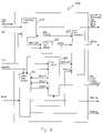
- FIG. 9is a flow chart diagram illustrating the operational steps for calibrating a temperature sensing transponder of one embodiment of the present invention.
- FIG. 10is a flow chart illustration of the operational steps for transmitting a temperature value from a temperature sensing transponder of one embodiment of the present invention.
- FIG. 11is a block diagram illustration of an ID telegram for transmitting an identification code using a FDXA transmission
- FIG. 12is a block diagram illustration of an ID telegram for transmitting temperature information using a FDXA transmission
- FIG. 13is a block diagram illustration of an ID telegram for transmitting an identification code using a FDXB transmission
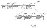
- FIG. 14is a block diagram illustration of an ID telegram for transmitting an identification code and temperature information using a FDXB transmission.
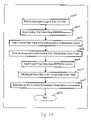
- FIG. 15is a flow chart illustration of the operational steps of a scanner and temperature sensing transponder system of one embodiment of the present invention.
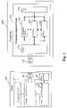
- FIG. 1a block diagram representation of a transponder system including a reader 100 and temperature sensing transponder 104 of one embodiment of the present invention is illustrated.
- the reader 100is similar to traditional readers associated with passive transponder devices, and includes a user interface/input 108 , reader electronics 112 , a reader antenna 116 , a display/output 120 , and a power source 124 .
- the reader 100is operable to transmit and receive information over the reader antenna 116 .
- the readercould have separate transmit and receive antennas, including multiple receive antennas permitting differential detection techniques which are well known in the art.
- the reader electronics 112are operable to initiate a signal transmission over the reader antenna 116 , and read a response signal which is received at the reader antenna 116 .
- the response signalcontains encoded information, as will be described in more detail below.
- the reader electronics 112demodulate the response signal and read the encoded information.
- the display/output 120may be used to display information contained in the response signal to a user, or output the information to an external device, such as an external display, printer, computer system, communication device, or storage device.
- the user interface/input 108may include a simple pushbutton interface on a reader 100 , which a user may depress to initiate an interrogation from the reader 100 .
- the user interface/input 108may also include more sophisticated keypad type interface, or a connection to an external device, such as a computer system or communication device.
- the reader 100also includes a power source 124 , which supplies power to the reader 100 and associated components.
- the power source 124may be internal batteries which are installed in the reader 100 .
- the power sourcemay also have a connection to an external AC or DC source of power in addition to, or instead of, batteries.
- the transponder 104includes an antenna coil 128 , and a transponder integrated circuit 132 .
- the antenna coil 128carries out both receive and transmit functions such as those traditionally associated with implantable transponders, and are well known in the art. While a single antenna coil 128 is illustrated, the transponder 104 could have separate transmit and receive antenna coils.
- An interrogation signal from the reader 100is received at the antenna coil 128 , and communicated to the transponder integrated circuit 132 .
- the transponder integrated circuit 132includes an interface portion 136 , a temperature sensing portion 140 , a processing portion 144 , a memory portion 148 , and a set of test pads 152 .
- the transponder integrated circuit 132upon receiving the interrogation signal, determines the temperature of the transponder 104 using the temperature sensing portion 140 , and retrieves identification information from the memory portion 148 . The transponder integrated circuit 132 then transmits identification and temperature information over the antenna coil 128 through the interface portion 136 .
- the processing portion 144processes information and communicates with different portions of the transponder integrated circuit 132 .
- the test pads 152link input signals to the processing portion and the memory portion during the initial circuit testing, temperature calibrating and identification programming processes, as will be described in further detail below. The determination of the temperature and identification information, as well as the format which is used for the transmitting of the identification and temperature information will be described in more detail in the discussion of FIGS. 2 through 15 .
- the interface portion 136includes a tune circuit 200 , a modulator and current limiter circuit 204 , a clock extract circuit 208 , a full wave rectifier circuit 212 , a voltage regulator circuit 216 , and a power on reset circuit 220 .
- the tune circuit 200receives an input signal SOC[0:4] from the memory portion 148 and trims the capacitance of the antenna so as to tune the antenna coil 128 to its optimal efficiency.
- the tune circuit 200and its calibration, will be described in more detail below.
- the modulator and current limiter circuit 204receives an input signal MOD from the processing portion 144 and modulates the information onto a carrier signal to create the response signal which is transmitted to the reader 100 through the antenna coil 128 . In addition to modulating the information received from the processing portion 144 , the modulator and current limiter circuit 204 limits the current that may enter the processing portion 144 , temperature sensing portion 140 , and memory portion 148 , in order to help protect the transponder integrated circuit 140 from damage which may result from high current.
- the clock extract circuit 208receives the interrogation signal, and produces a clock signal CLK which is used as a clock for those components within the transponder integrated circuit 104 which require a clock.
- the clock extract circuit 208uses the interrogation signal to generate the clock signal CLK by dividing the frequency of the interrogation signal by a predetermined amount to generate a system clock.
- the full wave rectifier circuit 212rectifies the received interrogation signal, and produces a direct current (DC) power supply VOUT.
- the DC power supply VOUTis then connected to the voltage regulator circuit 216 , power on reset circuit 220 , and the memory portion 148 .
- the voltage regulator 216regulates the DC power supply VOUT signal to provide a regulated output signal VDD and VSS to power other components within the transponder integrated circuit 104 .
- the voltage regulator circuit 216also provides a DC bias current IBP which is used in a sense amplifier located within the memory portion 148 .
- the power on reset circuit 220outputs a signal POR when the input signal VOUT reaches a predetermined threshold level. This is used to ensure that enough power is obtained to operate the transponder properly and to verify that all of the components start operation from a known state.
- the major signals communicated between different portions of the transponder integrated circuitare now described.
- the major signals communicated between the interface portion 136 and remaining portions of the integrated circuitinclude VOUT, VDD, IBP, VSS, POR, CLK, MOD and SOC[0:4], as were described with reference to FIG. 2 .
- the major signals communicated between the temperature sensing portion 140 and processing portion 144include A/D_COUNT, AD_CNT_EN, AT[0:4], CCK, TT, MCLK and NAD_RESET.
- A/D_COUNTis a digital value representing temperature-proportional analog current which is generated by a temperature sensor within the temperature sensing portion 140 .
- the temperature sensor and the A/D converterwill be described in more detail below with reference to FIG. 4 and FIG. 5 .
- AD_CNT_ENis the A/D converter enable signal. When the AD_CNT_EN signal is high, the A/D converter is selected to convert temperature into a digital value A/D_COUNT.
- AT[0:4]is an analog temperature trim value used to trim the analog current portion of the temperature sensor circuitry. The value is determined during the temperature calibration process, which will be described in further detail in FIG. 9 .
- CCKis the clock used by the A/D converter in the temperature sensing circuit.
- TTis the signal used to indicate transmission of temperature data. Temperature data is transmitted when TT is high.
- MCLKis the clock used by the A/D converter and it is equal to CLK/2.
- NAD_RESETis the active low A/D reset signal and is used to reset the A/D converter before a conversion.
- the major signals communicated between processing portion 144 and memory portion 148include A[0:7], ERASE, WRT, WRS[0:3], WR[0:15], SM, SOL[0:4], LDREN and LTRM[0:4].
- A[0:7]is an 8-bit address bus for accessing the memory portion 144 .
- ERASEis the signal for erasing the memory, and the memory is erased when ERASE is high.
- WRTis the signal for writing into the memory, and the memory may be written to when WRT is high.
- WRS[0:3]are write select bits used to select the row of memory to write when used in combination of active high WRT.
- WR[0:15]are digital test register bits.
- SMis the single memory bit output from the memory.
- SOL[0:4]are raw bits from the memory that indicate antenna tune trim values.
- LDRENis logic drive enable. When LDREN is high, the antenna tune trim bits from the digital test register are output from the memory.
- LTRM[0:4]are logic trim bits used to drive antenna tune selection when LDREN is high.
- test pads 152 and processing portion 144 and memory portion 148include VSS, TST, DIN, DATO, SCLK, CE 2 , CE, VPP.
- VSSis a ground signal.
- TSTis an input signal used to decode the control register into meaningful codes. The rising edge of TST is used to generate a global reset on the chip to synchronize modulation output with CLK.
- SCLKis the serial clock signal used to shift in input data (DIN) or shift out output data (DATO) for the processing portion 144 .
- DINis the input data used in combination with SCLK to select test modes as well as program the memory portion 148 .
- DATOis the output data used in combination with SCLK to shift out digital test register bits.
- CE 2is a chip enable signal for the processing portion 144 , which is used to activate a test mode.
- CEis the chip enable signal for the memory portion 148 , which is used in combination with WRT/ERASE to write into/erase the memory portion 148 .
- VPPis the high voltage power supply for programming the memory portion 148 .
- the temperature sensing portion 140includes a temperature sensor 400 , a current trim circuit 404 , and an A/D converter circuit 408 .
- the temperature sensor 400utilizes the temperature-proportional characteristic of P-N junction voltage to sense the temperature of the P-N junction. It has been known that a semiconductor P-N junction, in a bipolar junction transistor for example, exhibits a strong thermal dependence. The base-emitter voltage of a bipolar junction transistor decreases almost linearly with temperature. The temperature coefficient is dependent on the emitter current density, with lower current densities associated with higher temperature coefficients.
- a temperature-proportional current ITEMP 1is derived from the corresponding P-N junction voltage.
- a temperature-independent current IREF 1is derived from the bandgap reference voltage. The details of a basic temperature sensor will be described in more detail in connection with FIG. 5 .
- the current trim circuit 404trims IREF 1 and ITEMP 1 to IREF and ITEMP respectively, based on the input signal AT[0:4], which is delivered from the memory portion 148 .
- the A/D converter circuit 408converts the ratio of ITEMP/IREF to a digital count value A/D_COUNT.
- the temperature sensor circuit 400includes a first bipolar junction transistor portion Q 1 500 , and a second bipolar junction transistor portion Q 2 504 .
- the second bipolar junction transistor portion Q 2 504 having eight transistorsresults in the collective surface area of the base-emitter P-N junctions of Q 2 504 being eight times that of Q 1 500 .
- the surface area of Q 2 in this embodimentis approximately 8 times of the surface area of Q 1 .
- the second bipolar junction transistor portion 504may include a single, or multiple, transistors having a base-emitter P-N junction which has approximately eight times the surface area as the base-emitter P-N junction of the first bipolar junction transistor portion 500 .
- Other alternatives, and ratios of P-N junction surface area,may also be used, providing that they provide a suitable ratio of emitter current density for the bipolar junction transistor portions 500 , 504 .
- the emitter of Q 1 500is connected to an offset compensated operational transconductance amplifier OTA 1 508 .
- the emitter of Q 2 504is connected to a resistor R 1 512 , which is connected to the amplifier OTA 1 508 .
- Two P-channel metal-oxide semiconductor field-effect transistors MP 2 516 and MP 3 520form a current mirror circuit that regulates the emitter current density for Q 1 500 and Q 2 504 .
- the temperature-proportional characteristic of VDBEenables IC transistors to produce output signals that are proportional to absolute temperature.
- the temperature-proportional current IDBEcan be mirrored as ITEMP 1 using the current mirror circuit formed by MP 1 524 and MP 3 520 .
- the current through MP 4 528is also the mirror current of MP 1 524 and MP 3 528 .
- the resistor R 2 532is connected to amplifier OTA 2 534 .
- the current through MP 5 536is the mirror current of MP 6 540 , which is equal to the current VBE 2 /R 2 .
- the current through MP 4is the mirror current of MP 3 , which is equal to the current VDBE/R 1 .
- IREF and ITEMP 1can be read by the A/D converter 408 .
- the temperature sensor circuit 400is fabricated on a silicon integrated circuit, however, other types of semiconductor materials may be used, such as gallium-arsenide or germanium, for example.
- thermosensorsuch as a temperature sensor that employs more or fewer transistors in the bipolar junction transistor portions 504 , 508 , or a temperature sensor which utilizes diodes rather than bipolar junction transistors.
- the voltage drop on the P-N junctionsmay be used to determine the actual temperature of the transponder.
- the processing portion 144includes a transponder logic circuit 600 , a test multiplexer circuit 604 , a test register circuit 608 , a 24-bit shift register circuit 612 and a 16-bit trim register circuit 616 .
- the external signals which are received at the processing portion 144include CLK, POR, A/D_COUNT, SM, TST, SOL[0:4], and SCLK.
- the processing portion 144delivers external signals to other portions of the transponder, which include CE 2 , DIN, AD_CNT-EN, NAD_RESET, CCK, MCLK, A[0:7], MOD, AT[0:4], TT, WRT, ERASE, LDREN, LTRM[0:4], WR[0:15], DATO and WRS[0:3]. Details of these signals were discussed in connection with FIG. 3 .
- BNAInternal signals within the processing portion 144 include BNA, DT[5:0], T[15:0], TRIM_CLK, TRIM_EXT, WR[13:0], NLD_T 1 , NLD_T 2 and WRS[4:7].
- BNAis the signal used to select either a B mode transponder (when BNA is high) or an A mode transponder (when BNA is low).
- the A and B mode transponder settingcorresponds to the type of response signal which is transmitted by the transponder, namely if the required response signal from the transponder is an FDXA type signal, the A mode is selected. Likewise, if the required response signal from the transponder is an FDXB type signal, the B mode is selected.
- FDXA and FDXB transmissionsare ISO standard transmission formats, and will be discussed in more detail below.
- DT[5:0]are digital temperature trim bits. These digital temperature trim bits are set based on a calibration of the temperature sensing portion 140 , and will be discussed in more detail below.
- T[15:0]are internal trim bits.
- TRIM_CLKis the trim clock.
- TRIM_EXTis the trim extract.
- WR[13:0]are digital test register bits.
- NLD_T 1signals loading for T[15:0] into a shift register when active low.
- NLD_T 2signals loading for SOL[0:4] into a shift register when active low.
- WRS[4:7]are test modes select bits.
- the transponder logic circuit 600generates A/D converter control signals AD_CNT_EN and NAD_RESET, memory addresses A[0:7], clock signals CCK and MCLK, and a modulation signal MOD.
- the test multiplexer circuit 604multiplexes either T[15:0] or WR[13:0] onto trim buses AT[0:4], DT[5:0], and nets BNA, TT based on the state of TRIM_EXT.
- T[4:0]AT[4:0]
- T[10:5]DT[5:0]
- WR[13:11] and T[13:11]are spare bits, which may be used for specialized applications.
- TRIM_EXTis always low and T[15:0] drives the buses and nets, and only during test modes is TRIM_EXT temporary driven high, cleared on reset or writing a clear control code.
- the test register circuit 608contains logic used to decode WRS[4:7] into specific test modes.
- the test modesare used to write and erase the memory, force the MOD line to be inactive, turn off the A/D converter, and load trim values into the 24 bit shift register. Details of the sequence of testing, tuning, calibrating and programming will be described in connection with FIG. 8 .
- the 24-bit shift register 612shifts in 8 control bits and 16 data bits used to program row values for the memory, selects test modes, and generally controls the test register circuit 608 .
- the 16-bit trim register 616outputs trim bits T[15:0] with the input signal SM.
- SMis the single memory bit output from the memory portion 148 .
- FIG. 7a flow chart illustration of the operations for testing, tuning, calibrating and programming of the transponder integrated circuit is now described.
- the operations associated with FIG. 7are performed using an automatic tester during the manufacturing process, while the integrated circuits are still on the semiconductor wafer used for fabrication. Testing, calibration, tuning and programming may thus be completed relatively quickly and easily by the automatic test equipment, eliminating the need to individually test and calibrate each completely packaged transponder.
- the operations associated with FIG. 7may be performed at other times, such as after assembly of the integrated circuit into packages, or after the integrated circuits are cut into dies but before packaging.
- the sequenceis divided into six steps. Initially, the tester starts the sequence, as noted by block 700 .
- a global eraseis performed to carry out an initial erase of the memory portion 148 to all zeros.
- the memory portionis any suitable memory device, such as a programmable read only memory.
- the memory portion 148is an electronically erasable programmable read only memory (EEPROM or flash memory).
- An initial check out, to determine if the die is functioning and further testing and calibration is warranted,is carried out, as noted by block 708 .
- antenna tuning to tune the antenna to its optimal efficiency by trimming its capacitanceis performed.
- Temperature calibration to calibrate the temperature sensor of the transponder integrated circuitis performed, according to block 716 .
- the memory portionis programmed to store a unique identification associated with the transponder, transponder selection code to select a type A or type B transponder, analog temperature trim value and digital temperature trim value.
- a final check outis performed to ensure that the appropriate data has been programmed to memory and that the calibration has been carried out appropriately.
- the sequenceis then complete, as noted by block 728 . It will be understood that the above order in which the sequence is performed may be modified, and steps may be combined, where appropriate for certain applications.
- the procedure, in one embodiment, for chip testinginvolves powering the chip by applying a 134 kHz sine wave carrier to antenna pins, which are included in the test pads.
- a wafer probe card that contains a transformer circuit and a demodulator circuitserves as an interface between the 134 kHz sine wave source, the transponder integrated circuit, and the automatic tester.
- the 134 kHz carrier signalis rectified by the transponder integrated circuit to generate the chip VDD.
- the carrier frequencyis also used as the internal chip clock frequency CLK for the digital logic.
- a serial wordis shifted into the chip test register. The data is presented to a test pad as the signal DIN and clocked by serial data clock SCLK.
- the data clock frequencycan be a 1 ⁇ to 4 ⁇ multiple of the carrier frequency CLK.
- the serial wordconsists of a concatenated 8-bit control word, and a 16-bit data word.
- the 8-bit control wordrepresents the test mode and the 16-bit data word contains the input data.
- the action performed by the chip, when the test enable pin associated with signal CE 2 goes high,is determined by the contents of the 8-bit control word.
- the antenna tune circuit 200consists of a fixed capacitor C and five sets of trim capacitors, a first set C 0 and C 0 A, a second set C 1 and C 1 A, a third set C 2 and C 2 A, a fourth set C 3 and C 3 A, and a fifth set C 4 and C 4 A, that can be selected by the input trim signal SOC[0:4].
- the capacitance of Cis 257 pF
- the capacitances of C 0 and C 0 Aare 2 pF
- C 1 and CIAare 4pf
- C 2 and C 2 Aare 8 pF
- C 3 and C 3 Aare 16 pF
- C 4 and C 4 Aare 32 pF.
- the signals SOC[0:4]when active high, turn on the corresponding N-channel MOSFETs.
- MOSFETs MN 0 and MN 0 Aare turned on when SOC 0 is active high
- MOSFETs MN 1 and MN 1 Aare turned on when SOC 1 is active high
- MOSFETs MN 2 and MN 2 Aare turned on when SOC 2 is active high
- MOSFETs MN 3 and MN 3 Aare turned on when SOC 3 is active high
- MOSFETs MN 4 and MN 4 Aare turned on when SOC 4 is active high.
- the trim capacitors which are associated with the MOSFETsare added to the fixed capacitor C.
- an additional trim capacitance of 20 pF(0 ⁇ 2 pF+1 ⁇ 4 pF+0 ⁇ 8 pF+1 ⁇ 16 pF+0 ⁇ 32 pF) is added to the fixed 257 pF capacitance.
- SOC[0:4]can vary between 00000 to 11111, representing an additional 0 pF to 62 pF trim capacitance to the 257 pF capacitance.
- the total tuned capacitance (CT)can then be trimmed to a specific value between 257 pF to 319 pF. It will be understood that other values of the capacitors may be used, depending upon the application in which the transponder is to be used, as will be readily understood by one of ordinary skill in the art.
- the tune circuit 200which is associated with the antenna 128 , typically comprises an inductance, designed as a coil, and a capacitance, formed by means of a capacitor.
- the antenna 128is tuned to its optimal efficiency if the tuned capacitance (CT) matches the inductance of the antenna coil 128 to provide an optimal antenna voltage.
- CTtuned capacitance
- the antenna tuning processis performed by the automatic tester during the wafer probe operation.
- a wafer probe card that contains a demodulator circuitwill serve as an interface between the 134 kHz sine wave source, the transponder integrated circuit 132 , and the automatic tester.
- a specific 8-bit control word that represents antenna tuning test modeis first shifted into the chip test register.
- the control worddisables the modulation to allow for more accurate trimming of the on chip capacitor.
- the demodulator circuithas a DC output that is proportional to the peak amplitude of the antenna voltage.
- the tuning procedureis to shift in a trial 5-bit antenna tune word (SOC[0:4]), bring the test enable pin CE 2 high, record the value of the demodulator DC output, then bring the test enable pin low. This procedure continues until an optimal 5-bit antenna tune word is found that produces the maximum DC output from the demodulator. A successive approximation procedure is used to produce the fastest convergence on the optimal antenna tune word.
- the optimal antenna tune wordis then stored into the chip memory.
- the temperature calibrationis performed, in one embodiment, during the testing of the temperature sensing transponder integrated circuit.
- the wafer, and thus the transponder integrated circuitis kept at a predetermined, known temperature on the tester chuck throughout the whole calibration process.
- the objective of the temperature calibrationis to calibrate the chip temperature sensor such that at a known temperature, a given digital word value A/D_COUNT is telemetered by the chip to the reader.
- the temperature calibrationis initiated at block 900 , and is performed in two major steps.
- the two major stepsare analog trim 904 and digital trim 908 .
- the analog portion of the temperature sensoris adjusted by the tester such that the proportional to temperature current generated by the temperature sensor is able to span a predetermined temperature range.
- the testerfirst shifts in an initial guess for the analog trim bits AT[0:4], which is based on an expected result based on the predetermined temperature of the test chuck.
- the analog trim temperature count valueis checked, as noted by block 916 . The check is performed when the test enable pin is brought high, resulting in a telegram being sent by the transponder integrated circuit to the wafer probe card's demodulator circuit.
- the demodulated telegramis decoded by the tester to find the 8-bit temperature count value.
- the testeras noted by block 920 , compares this temperature count value to a predetermined target range for the count value.
- the testeradjusts the analog trim bits, and shifts in the adjusted for the analog trim bits AT[0:4], and the operations associated with blocks 916 and 920 are repeated. If, at block 920 , the tester determines that the temperature count value is within the predetermined target range, this analog trim temperature count value is recorded by the tester and the analog trim value AT[0:4] is programmed into the memory, as noted by block 928 .
- the predetermined target range for the temperature count valueis ⁇ 8 counts.
- the analog trim valuemay be used to adjust the gain of the amplification portion of the temperature sensor, to adjust an offset, or both.
- the A/D converterwould be able to output a larger or smaller range of temperature values. If the analog trim value is used to adjust an offset, the value of the analog trim value may be simply added or subtracted to the analog trim temperature count, resulting in a consistent range of temperature values able to be output by the A/D converter. Adjustments to both the gain and offset may be used in certain applications which require a larger temperature range to be transmitted by the transponder.
- the initial operation in the digital trim stepis a calculation of the difference between the target count value and the indicated count value from block 928 as computed by the tester.
- this difference valueis programmed into the memory as the digital trim value DT[5:0].
- the calibrated temperaturecan be computed using the analog and digital trim values.
- the calibration operationis then complete, as noted by block 940 .
- a transpondermay include a sensor which is capable of sensing pressure.
- the sensormay output an analog signal, which is read by an analog to digital converter, and which is calibrated in a similar manner as described with reference to FIG. 9 .
- the transpondermay be embedded in other objects rather than an animal.
- the transponderreceives an interrogation signal from a scanner and rectifies the signal to generate the chip VDD power supply.
- the analog trim value AT[0:4] determined from calibration processis read from memory, as noted by block 1008 .
- the analog trim valueis applied to the analog portion of the temperature sensor, as noted by block 1012 .
- the temperature sensorsenses the temperature of the integrated circuit and converts the analog current ITEMP into a digital count value, according to block 1016 .
- the processing portionWhen it is time to telemeter the temperature data, the processing portion reads the digital trim value from the memory, as noted by block 1020 .
- a serial digital adder within the processing portiontakes the digital count value output from the A/D converter and adds the digital trim value, as noted by block 1024 .
- the corrected digital temperature count valueis then telemetered to the reader, as noted by block 1028 .
- the operationis then complete, as noted by block 1032 . Accordingly, neither of the analog and digital trim values are telemetered to the reader. The correction is automatically made within the transponder before the final temperature digital count value is telemetered to the reader.
- the transponderWhen transmitting information to the scanner, the transponder, in one embodiment, transmits a data sequence according to the ISO Standard 11785.
- ISO standard 11785is a well known standard which is widely used in telemetering identification data from a transponder to a reader.
- the ISO standardincludes two distinct transmission types, FDXA and FDXB, for transmitting information from a transponder to a reader.
- the transponder 104can be programmed to transmit using either FDXA or FDXB, by setting an A or B mode flag within the transponder integrated circuit.
- the transponder 104When transmitting temperature and identification information from the transponder 104 using an FDXA transmission, the transponder 104 first includes identification information in one or more FDXA transmissions, and then temperature information in one or more FDXA transmissions. In this embodiment, the transponder transmits the identification information stored in the memory 148 in an identification telegram.
- the FDXA signal containing the identification informationincludes several information fields, and is defined by the ISO 11785 standard. The signal is transmitted at 125 kHz, using amplitude modulation frequency shift keying (AM-FSK), which is read by the reader. The signal uses manchester encoding, and has a bit rate of 1250 bits/second.
- the ID telegram structure 1100as illustrated in FIG. 11 , includes two information fields.
- a header 1104is included as the first 16 bits of the ID telegram 1100 .
- Following the header 1100is an 80 bit identification code field 1108 , having 70 identification bits and 10 parity bits. The total structure is thus 96 bits. Because the signal uses Manchester encoding, the actual number of information bits transmitted in the telegram structure is reduced because the manchester encoding includes clock information, as is well understood in the art.
- a first data block 1112contains parity data and a first portion of identification data.
- the parity dataincludes two binary bits, and the first portion of identification data contains the first 14 identification bits from the identification information stored in memory 148 .
- a second data block 1116contains parity data and a second portion of identification data.
- the parity dataincludes two binary bits, and the second portion of identification data contains identification bits 15 through 28 from the identification information stored in memory 148 .
- a third data block 1120contains parity data and a third portion of identification data.
- the parity dataincludes two binary bits, and the third portion of identification data contains identification bits 29 through 42 from the identification information stored in memory 148 .
- a fourth data block 1124contains parity data and a third portion of identification data.
- the parity dataincludes two binary bits, and the third portion of identification data contains identification bits 43 through 56 from the identification information stored in memory 148 .
- a fifth data block 1128contains parity data and a fifth portion of identification data.
- the parity dataincludes two binary bits, and the fifth portion of identification data contains identification bits 57 through 70 from the identification information stored in memory 148 .
- the identification code stored in memory 148is a 10-digit hexadecimal number with the odd digits being hexidecimal 8 or less, allowing manchesterencoding in three bits, while the even digits are encoded using four Manchester encoded bits, thus allowing any hexadecimal digit.
- the transponder 104also transmits information related to temperature to the scanner in a temperature telegram.
- the temperature informationis encoded in a temperature telegram structure 1200 , as illustrated in FIG. 12 .
- the temperature telegram structure 1200includes several data fields. First, the temperature telegram structure 1200 has a header field 1204 which has 16 bits. Following the header field 1204 is a temperature data and error checking field 1208 .
- the temperature data and error checking fieldcontains 80 bits, and is divided into five separate data blocks.
- a first data block 1212contains 16 temperature data bits, which is 8 manchester encoded data bits.
- a second data block 1216contains 16 error checking bits, which in one embodiment are hexadecimal 5555 .
- a third data block 1220contains 16 temperature data bits, which is 8 manchester encoded data bits.
- a fourth data block 1224contains 16 error checking bits, which in one embodiment are hexadecimal 5555 .
- a fifth data block 1228contains 16 temperature data bits, which is 8 manchester encoded data bits. The total structure is thus 96 bits.
- the telegram structure used to transmit temperature informationmay be used, such as, for example, the temperature information being contained in the first field, with the remainder of the telegram structure being filled with stuffing bits. If more or fewer bits are used to encode the temperature information, the fields in the telegram structure would be adjusted to accommodate the larger or smaller number of bits used for the temperature information. Furthermore, the total number of bits transmitted for a telegram structure to transmit temperature information may be adjusted. For example, a shorter telegram structure may be used which contains merely a header, temperature information, and error checking information.
- the transponderWhen transmitting the identification information and the temperature information, the transponder uses an auto transmission format due to having to use two distinct telegram structures to transmit the identification and temperature information.
- the transpondertransmits a predetermined number of ID telegram structures 1100 having the identification information, and then transmits a predetermined number of temperature telegram structures 1200 having the temperature information.
- three identification telegram structures 1100are sent sequentially, and then one temperature telegram 1200 is sent. This is repeated as long as an interrogation signal is present at the transponder.
- the headers in each of the ID telegram structuresare unique which enables a scanner to determine whether the telegram contains identification or temperature information.
- the identification telegram 1100may include a header 1104 having the following binary bits in the header: 0101 0101 0001 1101.
- the temperature telegram structure 1200may include the following binary bits in the header 1204 : 1010 1010 1110 0010.
- the readeris able to determine the telegram structure type, temperature or identification, from the information contained in the header field.
- a scanner which is not programmed to read temperature informationmay still be used to obtain identification information, because the identification information is contained in an ID telegram structure which is widely used and well known, namely a structure which conforms to the ISO 11785 standard.
- the reader and transponderoperate in a full-duplex transmission, with the reader continuously transmitting an interrogation signal while also receiving the information from the transponder.
- the transpondertransmits the ID telegrams and temperature telegrams continuously, with no pauses between telegrams.
- other transmission schemessuch as burst transmissions, half-duplex, or pausing between telegrams could also be used.
- the transponderWhen transmitting information to the scanner using an FDXB transmission, the transponder, transmits a data structure which contains both identification information as well as temperature information.
- the FDXB signal containing the identification informationincludes several information fields, and is also defined by the ISO 11785 standard.
- the signalis transmitted at 134.2 kHz, using amplitude shift keying (ASK) modulation, which is read by the reader.
- the signaluses modified differential bi-phase (DBP) encoding, and has a bit rate of 4194 bits/second.
- the ID telegram structure 1300as illustrated in FIG. 13 , includes several information fields.
- a header 1304is included as the first 11 bits of the structure. Following the header 1304 is a 72 bit identification information field 1308 .
- the identification information field 1308contains 64 identification bits, and 8 control bits. Following the identification information field 1308 is an 18 bit CRC field 1312 .
- the CRC field 1312includes 16 CRC bits, and 2 control bits.
- a trailer field 1316Following the CRC field 1312 , is a trailer field 1316 , having 27 bits.
- the trailer field 1316includes 24 trailer bits, and 3 control bits.
- the trailer field 1316includes three data blocks.
- a first data block 1320contains 8 trailer bits and one control bit.
- a second data block 1324contains 8 trailer bits and one control bit.
- a third data block 1328contains 8 trailer bits and one control bit. The total structure is thus 128 bits.
- the transponderalso transmits information related to temperature to the scanner.
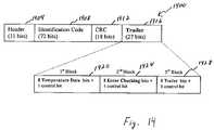
- the temperature informationis encoded in the ID telegram structure 1400 , as illustrated in FIG. 14 .
- the ID telegram structure 1400includes several data fields.
- a header 1404is included as the first 11 bits of the structure. Following the header is a 72 bit identification information field 1408 .
- the identification information fieldcontains 64 identification bits, and 8 control bits.
- Following the identification information field 1408is an 18 bit CRC field 1412 .
- the CRC field 1412includes 16 CRC bits, and 2 control bits. Following the CRC field 1412 , is a trailer field 1416 , having 27 bits.
- the trailer field 1416includes a first block 1420 , a second block 1424 , and a third block 1428 , with each block having 9 bits.
- the first block 1420contains temperature information, and has 8 temperature bits, and one control bit.
- the transponderencodes the digital temperature information into an 8 bit temperature data block, which can be used by the scanner to indicate the temperature of the transponder.
- the second block 1424contains 8 error checking bits, and one control bit
- the third block 1428contains 8 trailer bits and 1 control bit. The total structure is thus 128 bits.
- the temperature informationmay be encoded in the trailer field in alternative manners, such as, for example, the second block containing the temperature information, with the first and third trailer fields containing trailer or error checking bits and a control bit. Furthermore, if the temperature information is contained in more or fewer data bits, the trailer or error checking fields can be modified to contain the appropriate temperature information and error checking information.
- the transponderWhen transmitting the identification and temperature information, the transponder uses an auto transmission format which acts to transmit the identification and temperature information continuously. Since the telegram structure contains both the identification and temperature information, it is not necessary to transmit a second telegram structure containing temperature information separately from a first telegram structure containing identification information, as is the case in an FDXA transmission.
- the telegram structureincludes a header having the following binary bits in the header: 00,000,000,001.
- the scanneris able to determine the telegram structure type from the information contained in the header field. As mentioned above, the scanner and transponder operate in a full duplex mode with no pause between successive telegrams, but could readily be modified to transmit in half-duplex mode or with pauses between telegrams.
- the transpondertransmits identification and temperature information in standardized form according to the ISO standard 11785, this allows readers which are not programmed to receive temperature information to continue to receive identification information.
- a reader which is not capable of reading temperature informationmay be used to scan a transponder which is capable of transmitting temperature information according to one of the embodiments of the present invention.
- the transponderwill transmit both the identification information, and the temperature information, as described above. If the reader is capable of reading standard FDXA or FDXB transmissions, the reader will be able to read the identification information contained in the transmissions. This allows for additional readers, which may not be capable of reading temperature information transmitted by the transponder, to be used for identification purposes, and can help identify a host even if a user is not using a reader which is capable of reading temperature information.
- the scanneris used to transmit an RF field to the transponder, as noted by block 1500 .
- the transponderreceives the RF field, and uses energy from the RF field to power on the transponder integrated circuit, at noted by block 1504 .
- the transponderpowers on, it resets all of the components, reads the configuration data for the transponder which is stored in memory, and determines the transponder type.
- the transponder typeis, in one embodiment, an FDXA or an FDXB transponder, which is set during the initial programming and testing of the transponder.
- the transpondercan be reprogrammed, and change transponder types based on the reprogramming, i.e., from FDXA to FDXB or vice-versa.
- reprogrammingmay be performed in the field, using a reader which is operable to transmit a signal containing data which the transponder can read and store in memory.
- readers and transponders associated therewithare known in the art.
- a transpondermay be programmed to recognize a flag from a reader, and transmit.
- the transponderruns in a default read mode, as noted by block 1508 .
- the transpondertransmits the appropriate modulated RF field to the scanner, which contains both identification and temperature information.
- the scannerafter starting transmission of the transmit RF field, enters a read mode, where it waits to receive the modulated RF field from the transponder, as noted by block 1512 .
- the scannerreceives the modulated RF field, it decodes the identification and temperature information.
- the scannerdetermines if the identification and temperature information were successfully decoded at block 1516 . If the scanner was successful in decoding the information, it stores the identification and temperature data, as noted by block 1520 .
- the scannerhas a memory which can store a predetermined amount of identification and temperature information, which can be transferred to a computer or other device for monitoring over a period of time.
- the scannerdisplays the identification and temperature information on a display, which a user can use to verify that a successful reading was obtained.
- the scannerdetermines whether it should continue searching, as noted by block 1528 .
- the scannermakes this determination, in one embodiment, according to whether a user continues pressing a send button on the scanner. If the scanner determines that it is to continue searching, it returns to block 1512 . If the scanner determines that it is not to continue searching, it displays an error message on the display, as noted by block 1532 . In one embodiment, the scanner displays “No ID Found” on the display, indicating to the user that the scan was not successful in returning identification or temperature information.
- the scannerafter displaying either the identification and temperature information at block 1524 , or displaying the error message at block 1532 , then determines if another scan is requested, as noted by block 1536 . In one embodiment, the scanner makes this determination according to whether a user is pressing a send button on the scanner. If the scanner determines that it is to scan again, it returns to block 1512 . If the scanner determines that it is not to scan again, it powers off, as noted by block 1540 .
- the transpondermay also collect other information from a host animal or other object in which the transponder is embedded, such as pressure, PH, blood sugar, blood oxygen, heart rate, or other diagnostic measurement.
- other informationsuch as pressure, PH, blood sugar, blood oxygen, heart rate, or other diagnostic measurement.
- the transponder transmits using FDXAit cycles through several transmissions to complete the transfer of all of the information collected. If the transponder transmits using FDXB, the additional information may be transmitted in the remaining trailer which is not used by the temperature information.
- the transponderis programmable to change transmission modes.
- the transponderis programmed during testing and calibration, prior to being implanted into the host animal to transmit using either FDXA or FDXB transmission.
- the transpondermay be field programmable and can be programmed even after being implanted into the host animal. The programming is accomplished using electronically erasable programmable read only memory (EEPROM or flash memory).
- EEPROMelectronically erasable programmable read only memory
- the transpondermay be programmed either during the test portion of the fabrication process, or in the field using the scanner which has a mode which is capable to write to the memory.
- the memory in the transponderis capable of being programmed by the transponder, and can store information other than identification information to transmit to a scanner.
- the transpondermay be programmed with an owner's name and/or telephone number.
- the transponderis able to be programmed with the additional information following the manufacturing process.
- a scannermay have a programming mode, which is used by the transponder to program the additional information.
- the transponderwill transmit the additional information when it transmits the identification and temperature information. This may be done, in the case of an FDXA enabled transponder, by adding another transmission after the identification and temperature transmissions, which contains the information.
- the additional bits in the trailermay be used to transmit this additional information, or the transponder may recycle and send another telegram containing additional information.
- a transpondermay be programmed with additional information, including history information, about the host, such as name, last medical examination date, last vaccination, and other similar information.
- history informationabout the host
- a veterinarianmay have a scanner which receives this information from the transponder when an animal initially begins treatment. The veterinarian may than have a record of the animal's name, body temperature, last examination, last vaccination, and other information prior to beginning the next examination.
- the transpondercan be programmed with updated information, using a scanner which is capable of transmitting programming information to the transponder.
- transponderdescribed above with reference to the drawing figures has been discussed primarily in reference to sensing a body characteristic of a host animal, it will be understood that other applications exist for the use of such a device.
- a transpondermay be used in transferring materials which are required to be kept at a certain temperature, for example, organ transfers and transporting perishable food in a refrigeration truck.
- other industrial applicationsexist, such as a transponder capable of sensing the temperature of a component of a machine or other apparatus. The above described invention may be used in such applications to identify a body characteristic associated with the body in which the transponder is embedded or mounted.
Landscapes
- Engineering & Computer Science (AREA)
- Life Sciences & Earth Sciences (AREA)
- Physics & Mathematics (AREA)
- General Physics & Mathematics (AREA)
- Environmental Sciences (AREA)
- Computer Hardware Design (AREA)
- Microelectronics & Electronic Packaging (AREA)
- Computer Networks & Wireless Communication (AREA)
- Animal Husbandry (AREA)
- Biodiversity & Conservation Biology (AREA)
- Theoretical Computer Science (AREA)
- Crystallography & Structural Chemistry (AREA)
- Birds (AREA)
- Chemical & Material Sciences (AREA)
- Zoology (AREA)
- Signal Processing (AREA)
- Arrangements For Transmission Of Measured Signals (AREA)
- Measuring Temperature Or Quantity Of Heat (AREA)
- Near-Field Transmission Systems (AREA)
- Character Discrimination (AREA)
- Geophysics And Detection Of Objects (AREA)
- Inspection Of Paper Currency And Valuable Securities (AREA)
- Radar Systems Or Details Thereof (AREA)
Abstract
Description
Claims (114)
Priority Applications (10)
| Application Number | Priority Date | Filing Date | Title |
|---|---|---|---|
| US10/114,875US7015826B1 (en) | 2002-04-02 | 2002-04-02 | Method and apparatus for sensing and transmitting a body characteristic of a host |
| DE60333828TDE60333828D1 (en) | 2002-04-02 | 2003-03-13 | METHOD AND DEVICE FOR DETECTING AND TRANSFERRING A BODY IDENTIFICATION OF A HOSTS |
| AU2003225811AAU2003225811B2 (en) | 2002-04-02 | 2003-03-13 | Method and apparatus for sensing and transmitting a body characteristic of a host |
| JP2003582730AJP4326970B2 (en) | 2002-04-02 | 2003-03-13 | Method and apparatus for detecting and transmitting host body characteristics |
| AT03746040TATE478397T1 (en) | 2002-04-02 | 2003-03-13 | METHOD AND DEVICE FOR DETECTING AND TRANSMITTING A HOST'S BODY SIZE |
| PCT/US2003/007985WO2003085617A1 (en) | 2002-04-02 | 2003-03-13 | Method and apparatus for sensing and transmitting a body characteristic of a host |
| EP03746040AEP1495456B1 (en) | 2002-04-02 | 2003-03-13 | Method and apparatus for sensing and transmitting a body characteristic of a host |
| BRPI0308963ABRPI0308963B1 (en) | 2002-04-02 | 2003-03-13 | method and apparatus for recognizing and transmitting a physical characteristic of a host |
| CA002481063ACA2481063C (en) | 2002-04-02 | 2003-03-13 | Method and apparatus for sensing and transmitting a body characteristic of a host |
| US10/634,311US7432825B2 (en) | 2002-04-02 | 2003-08-04 | Interrogation device and method for scanning |
Applications Claiming Priority (1)
| Application Number | Priority Date | Filing Date | Title |
|---|---|---|---|
| US10/114,875US7015826B1 (en) | 2002-04-02 | 2002-04-02 | Method and apparatus for sensing and transmitting a body characteristic of a host |
Related Child Applications (1)
| Application Number | Title | Priority Date | Filing Date |
|---|---|---|---|
| US10/634,311Continuation-In-PartUS7432825B2 (en) | 2002-04-02 | 2003-08-04 | Interrogation device and method for scanning |
Publications (1)
| Publication Number | Publication Date |
|---|---|
| US7015826B1true US7015826B1 (en) | 2006-03-21 |
Family
ID=28789807
Family Applications (2)
| Application Number | Title | Priority Date | Filing Date |
|---|---|---|---|
| US10/114,875Expired - LifetimeUS7015826B1 (en) | 2002-04-02 | 2002-04-02 | Method and apparatus for sensing and transmitting a body characteristic of a host |
| US10/634,311Expired - LifetimeUS7432825B2 (en) | 2002-04-02 | 2003-08-04 | Interrogation device and method for scanning |
Family Applications After (1)
| Application Number | Title | Priority Date | Filing Date |
|---|---|---|---|
| US10/634,311Expired - LifetimeUS7432825B2 (en) | 2002-04-02 | 2003-08-04 | Interrogation device and method for scanning |
Country Status (9)
| Country | Link |
|---|---|
| US (2) | US7015826B1 (en) |
| EP (1) | EP1495456B1 (en) |
| JP (1) | JP4326970B2 (en) |
| AT (1) | ATE478397T1 (en) |
| AU (1) | AU2003225811B2 (en) |
| BR (1) | BRPI0308963B1 (en) |
| CA (1) | CA2481063C (en) |
| DE (1) | DE60333828D1 (en) |
| WO (1) | WO2003085617A1 (en) |
Cited By (119)
| Publication number | Priority date | Publication date | Assignee | Title |
|---|---|---|---|---|
| US20040233971A1 (en)* | 2003-02-27 | 2004-11-25 | Meads Roger W. | Temperature recording system |
| US20050165317A1 (en)* | 2003-11-04 | 2005-07-28 | Turner Nicholas M. | Medical devices |
| US20050258961A1 (en)* | 2004-04-29 | 2005-11-24 | Kimball James F | Inventory management system using RFID |
| US20050275533A1 (en)* | 2002-11-04 | 2005-12-15 | Marko Hanhikorpi | Method for manufacturing a product sensor, and a product sensor |
| US20060065198A1 (en)* | 2004-08-16 | 2006-03-30 | Meads Roger W | Devices for improved milking |
| US20060145844A1 (en)* | 2004-12-23 | 2006-07-06 | Industrial Technology Research Institute | Temperature tracking and monitoring system used for commodities transportation |
| US20060198229A1 (en)* | 2004-02-19 | 2006-09-07 | Micron Technology, Inc. | Memory device having terminals for transferring multiple types of data |
| US20060279295A1 (en)* | 2003-02-25 | 2006-12-14 | Crook David T | Probe based information storage for probes used for opens detection in in-circuit testing |
| US20070046474A1 (en)* | 2005-08-26 | 2007-03-01 | Balachandran Ganesh K | Voltage regulation circuit for RFID systems |
| US20070170505A1 (en)* | 2005-12-27 | 2007-07-26 | Hajime Tokunaga | Semiconductor device and manufacturing method thereof |
| US20070194913A1 (en)* | 2003-09-11 | 2007-08-23 | Mitsubishi Materials Corporation | Wireless module,wireless temperature sensor,wireless interface device,and wireless sensor system |
| US20080012577A1 (en)* | 2006-05-26 | 2008-01-17 | Ge Healthcare Bio-Sciences Corp. | System and method for monitoring parameters in containers |
| US20080058652A1 (en)* | 2004-11-04 | 2008-03-06 | Payne Peter A | Medical Devices |
| US20080136646A1 (en)* | 2004-12-23 | 2008-06-12 | Atmel Germany Gmbh | Backscatter transponder |
| US20080200117A1 (en)* | 2007-02-19 | 2008-08-21 | Yair Oren | Method and system for improving uplink performance |
| AU2003225811B2 (en)* | 2002-04-02 | 2008-09-18 | Destron Fearing Corporation | Method and apparatus for sensing and transmitting a body characteristic of a host |
| WO2008133613A1 (en)* | 2007-04-26 | 2008-11-06 | Tagent Corporation | Embedding items with rfid tags for tracking and calibration |
| US20080312511A1 (en)* | 2007-06-14 | 2008-12-18 | Alberta Research Council Inc. | Animal health monitoring system and method |
| EP2020923A2 (en) | 2006-05-04 | 2009-02-11 | Cambridge Temperature Concepts Limited | In-situ measurement of physical parameters |
| US20090205584A1 (en)* | 2008-02-19 | 2009-08-20 | Masin Joseph V | Combined phone number and country code identifiers for ISO 11784/85 compatible transponders |
| US20090207001A1 (en)* | 2008-02-19 | 2009-08-20 | Masin Joseph V | Phone number and manufacturer identifiers for ISO 11784/85 compatible transponders and associated systems and methods |
| US20090206996A1 (en)* | 2008-02-19 | 2009-08-20 | Masin Joseph V | Phone number identifiers for ISO 11784/85 compatible transponders and associated systems and methods |
| US20090261953A1 (en)* | 2008-04-18 | 2009-10-22 | Hee Bok Kang | Radio frequency identification device |
| US20090323875A1 (en)* | 2008-06-30 | 2009-12-31 | International Business Machines Corporation | Method for Data Synchronization |
| US20090326410A1 (en)* | 2006-09-05 | 2009-12-31 | Fertility Focus Limited | Method of Detecting and Predicting Ovulation and the Period of Fertility |
| US20100023429A1 (en)* | 2006-04-13 | 2010-01-28 | Bolander Jarie G | Embedding items with rfid tags for tracking and calibration |
| US20100045446A1 (en)* | 2008-08-22 | 2010-02-25 | Electronics And Telecommunications Research Institute | Rfid system using human body communication |
| US20100170352A1 (en)* | 2008-03-27 | 2010-07-08 | Michael Petersen | Environment monitoring and recording tag with remote sensing capability |
| US20100217136A1 (en)* | 2003-11-04 | 2010-08-26 | L & P 100 Limited | Medical devices |
| US20100281301A1 (en)* | 2009-04-30 | 2010-11-04 | Paul Lepek | Circuit for a transponder and method for testing the circuit |
| US20110160548A1 (en)* | 2009-12-30 | 2011-06-30 | Avery Dennison Corporation | Apparatus and method for monitoring physiological parameters using electrical measurements |
| US20110181399A1 (en)* | 2010-01-28 | 2011-07-28 | Dvm Systems, Llc | Energy harvesting with rfid tags |
| US8015024B2 (en) | 2006-04-07 | 2011-09-06 | Depuy Products, Inc. | System and method for managing patient-related data |
| US8075627B2 (en) | 2006-04-07 | 2011-12-13 | Depuy Products, Inc. | System and method for transmitting orthopaedic implant data |
| US8080064B2 (en) | 2007-06-29 | 2011-12-20 | Depuy Products, Inc. | Tibial tray assembly having a wireless communication device |
| US8092412B2 (en) | 2005-06-30 | 2012-01-10 | Depuy Products, Inc. | Apparatus, system, and method for transcutaneously transferring energy |
| US8115635B2 (en) | 2005-02-08 | 2012-02-14 | Abbott Diabetes Care Inc. | RF tag on test strips, test strip vials and boxes |
| US8244368B2 (en) | 2005-06-30 | 2012-08-14 | Depuy Products, Inc. | Apparatus, system, and method for transcutaneously transferring energy |
| US8532492B2 (en) | 2009-02-03 | 2013-09-10 | Corning Cable Systems Llc | Optical fiber-based distributed antenna systems, components, and related methods for calibration thereof |
| US20130249599A1 (en)* | 2012-03-23 | 2013-09-26 | Seiko Instruments Inc. | Semiconductor device |
| US8548330B2 (en) | 2009-07-31 | 2013-10-01 | Corning Cable Systems Llc | Sectorization in distributed antenna systems, and related components and methods |
| US20130316653A1 (en)* | 2012-03-06 | 2013-11-28 | Waveconnex, Inc. | System for constraining an operating parameter of an ehf communication chip |
| US8632464B2 (en) | 2006-09-11 | 2014-01-21 | DePuy Synthes Products, LLC | System and method for monitoring orthopaedic implant data |
| US8639121B2 (en) | 2009-11-13 | 2014-01-28 | Corning Cable Systems Llc | Radio-over-fiber (RoF) system for protocol-independent wired and/or wireless communication |
| US8644844B2 (en) | 2007-12-20 | 2014-02-04 | Corning Mobileaccess Ltd. | Extending outdoor location based services and applications into enclosed areas |
| US8718478B2 (en) | 2007-10-12 | 2014-05-06 | Corning Cable Systems Llc | Hybrid wireless/wired RoF transponder and hybrid RoF communication system using same |
| US20140241397A1 (en)* | 2013-02-25 | 2014-08-28 | Kabushiki Kaisha Toshiba | Electronic thermometer, electronic thermometer system, and receiver |
| US8831428B2 (en) | 2010-02-15 | 2014-09-09 | Corning Optical Communications LLC | Dynamic cell bonding (DCB) for radio-over-fiber (RoF)-based networks and communication systems and related methods |
| US8867919B2 (en) | 2007-07-24 | 2014-10-21 | Corning Cable Systems Llc | Multi-port accumulator for radio-over-fiber (RoF) wireless picocellular systems |
| US8873585B2 (en) | 2006-12-19 | 2014-10-28 | Corning Optical Communications Wireless Ltd | Distributed antenna system for MIMO technologies |
| US8897215B2 (en) | 2009-02-08 | 2014-11-25 | Corning Optical Communications Wireless Ltd | Communication system using cables carrying ethernet signals |
| US8983301B2 (en) | 2010-03-31 | 2015-03-17 | Corning Optical Communications LLC | Localization services in optical fiber-based distributed communications components and systems, and related methods |
| US20150119752A1 (en)* | 2013-10-28 | 2015-04-30 | Arkis Biosciences | Implantable bio-pressure transponder |
| US9037143B2 (en) | 2010-08-16 | 2015-05-19 | Corning Optical Communications LLC | Remote antenna clusters and related systems, components, and methods supporting digital data signal propagation between remote antenna units |
| US9042732B2 (en) | 2010-05-02 | 2015-05-26 | Corning Optical Communications LLC | Providing digital data services in optical fiber-based distributed radio frequency (RF) communication systems, and related components and methods |
| US9158864B2 (en) | 2012-12-21 | 2015-10-13 | Corning Optical Communications Wireless Ltd | Systems, methods, and devices for documenting a location of installed equipment |
| US9178635B2 (en) | 2014-01-03 | 2015-11-03 | Corning Optical Communications Wireless Ltd | Separation of communication signal sub-bands in distributed antenna systems (DASs) to reduce interference |
| US9184960B1 (en) | 2014-09-25 | 2015-11-10 | Corning Optical Communications Wireless Ltd | Frequency shifting a communications signal(s) in a multi-frequency distributed antenna system (DAS) to avoid or reduce frequency interference |
| US9184843B2 (en) | 2011-04-29 | 2015-11-10 | Corning Optical Communications LLC | Determining propagation delay of communications in distributed antenna systems, and related components, systems, and methods |
| US9185674B2 (en) | 2010-08-09 | 2015-11-10 | Corning Cable Systems Llc | Apparatuses, systems, and methods for determining location of a mobile device(s) in a distributed antenna system(s) |
| US9240835B2 (en) | 2011-04-29 | 2016-01-19 | Corning Optical Communications LLC | Systems, methods, and devices for increasing radio frequency (RF) power in distributed antenna systems |
| US9247543B2 (en) | 2013-07-23 | 2016-01-26 | Corning Optical Communications Wireless Ltd | Monitoring non-supported wireless spectrum within coverage areas of distributed antenna systems (DASs) |
| US9258052B2 (en) | 2012-03-30 | 2016-02-09 | Corning Optical Communications LLC | Reducing location-dependent interference in distributed antenna systems operating in multiple-input, multiple-output (MIMO) configuration, and related components, systems, and methods |
| US9325429B2 (en) | 2011-02-21 | 2016-04-26 | Corning Optical Communications LLC | Providing digital data services as electrical signals and radio-frequency (RF) communications over optical fiber in distributed communications systems, and related components and methods |
| US20160117532A1 (en)* | 2013-08-22 | 2016-04-28 | Verily Life Sciences Llc | Using Unique Identifiers to Retrieve Configuration Data for Tag Devices |
| US9338823B2 (en) | 2012-03-23 | 2016-05-10 | Corning Optical Communications Wireless Ltd | Radio-frequency integrated circuit (RFIC) chip(s) for providing distributed antenna system functionalities, and related components, systems, and methods |
| US9357551B2 (en) | 2014-05-30 | 2016-05-31 | Corning Optical Communications Wireless Ltd | Systems and methods for simultaneous sampling of serial digital data streams from multiple analog-to-digital converters (ADCS), including in distributed antenna systems |
| US9385810B2 (en) | 2013-09-30 | 2016-07-05 | Corning Optical Communications Wireless Ltd | Connection mapping in distributed communication systems |
| US9419712B2 (en) | 2010-10-13 | 2016-08-16 | Ccs Technology, Inc. | Power management for remote antenna units in distributed antenna systems |
| US9420542B2 (en) | 2014-09-25 | 2016-08-16 | Corning Optical Communications Wireless Ltd | System-wide uplink band gain control in a distributed antenna system (DAS), based on per band gain control of remote uplink paths in remote units |
| US9455784B2 (en) | 2012-10-31 | 2016-09-27 | Corning Optical Communications Wireless Ltd | Deployable wireless infrastructures and methods of deploying wireless infrastructures |
| US9497706B2 (en) | 2013-02-20 | 2016-11-15 | Corning Optical Communications Wireless Ltd | Power management in distributed antenna systems (DASs), and related components, systems, and methods |
| US9509133B2 (en) | 2014-06-27 | 2016-11-29 | Corning Optical Communications Wireless Ltd | Protection of distributed antenna systems |
| US9525472B2 (en) | 2014-07-30 | 2016-12-20 | Corning Incorporated | Reducing location-dependent destructive interference in distributed antenna systems (DASS) operating in multiple-input, multiple-output (MIMO) configuration, and related components, systems, and methods |
| US9525488B2 (en) | 2010-05-02 | 2016-12-20 | Corning Optical Communications LLC | Digital data services and/or power distribution in optical fiber-based distributed communications systems providing digital data and radio frequency (RF) communications services, and related components and methods |
| US9531452B2 (en) | 2012-11-29 | 2016-12-27 | Corning Optical Communications LLC | Hybrid intra-cell / inter-cell remote unit antenna bonding in multiple-input, multiple-output (MIMO) distributed antenna systems (DASs) |
| US9549301B2 (en) | 2007-12-17 | 2017-01-17 | Corning Optical Communications Wireless Ltd | Method and system for real time control of an active antenna over a distributed antenna system |
| US9590733B2 (en) | 2009-07-24 | 2017-03-07 | Corning Optical Communications LLC | Location tracking using fiber optic array cables and related systems and methods |
| US9602210B2 (en) | 2014-09-24 | 2017-03-21 | Corning Optical Communications Wireless Ltd | Flexible head-end chassis supporting automatic identification and interconnection of radio interface modules and optical interface modules in an optical fiber-based distributed antenna system (DAS) |
| US9621293B2 (en) | 2012-08-07 | 2017-04-11 | Corning Optical Communications Wireless Ltd | Distribution of time-division multiplexed (TDM) management services in a distributed antenna system, and related components, systems, and methods |
| US9648580B1 (en) | 2016-03-23 | 2017-05-09 | Corning Optical Communications Wireless Ltd | Identifying remote units in a wireless distribution system (WDS) based on assigned unique temporal delay patterns |
| US9647758B2 (en) | 2012-11-30 | 2017-05-09 | Corning Optical Communications Wireless Ltd | Cabling connectivity monitoring and verification |
| US9653861B2 (en) | 2014-09-17 | 2017-05-16 | Corning Optical Communications Wireless Ltd | Interconnection of hardware components |
| US9661781B2 (en) | 2013-07-31 | 2017-05-23 | Corning Optical Communications Wireless Ltd | Remote units for distributed communication systems and related installation methods and apparatuses |
| US9673904B2 (en) | 2009-02-03 | 2017-06-06 | Corning Optical Communications LLC | Optical fiber-based distributed antenna systems, components, and related methods for calibration thereof |
| US9681313B2 (en) | 2015-04-15 | 2017-06-13 | Corning Optical Communications Wireless Ltd | Optimizing remote antenna unit performance using an alternative data channel |
| US20170166314A1 (en)* | 2015-12-09 | 2017-06-15 | The Boeing Company | System and method for aircraft ice detection within a zone of non-detection |
| US9684060B2 (en) | 2012-05-29 | 2017-06-20 | CorningOptical Communications LLC | Ultrasound-based localization of client devices with inertial navigation supplement in distributed communication systems and related devices and methods |
| US9685782B2 (en) | 2010-11-24 | 2017-06-20 | Corning Optical Communications LLC | Power distribution module(s) capable of hot connection and/or disconnection for distributed antenna systems, and related power units, components, and methods |
| US9699723B2 (en) | 2010-10-13 | 2017-07-04 | Ccs Technology, Inc. | Local power management for remote antenna units in distributed antenna systems |
| US9693689B2 (en) | 2014-12-31 | 2017-07-04 | Blue Spark Technologies, Inc. | Body temperature logging patch |
| US9715157B2 (en) | 2013-06-12 | 2017-07-25 | Corning Optical Communications Wireless Ltd | Voltage controlled optical directional coupler |
| US9729251B2 (en) | 2012-07-31 | 2017-08-08 | Corning Optical Communications LLC | Cooling system control in distributed antenna systems |
| US9729267B2 (en) | 2014-12-11 | 2017-08-08 | Corning Optical Communications Wireless Ltd | Multiplexing two separate optical links with the same wavelength using asymmetric combining and splitting |
| US9730228B2 (en) | 2014-08-29 | 2017-08-08 | Corning Optical Communications Wireless Ltd | Individualized gain control of remote uplink band paths in a remote unit in a distributed antenna system (DAS), based on combined uplink power level in the remote unit |
| US9775123B2 (en) | 2014-03-28 | 2017-09-26 | Corning Optical Communications Wireless Ltd. | Individualized gain control of uplink paths in remote units in a distributed antenna system (DAS) based on individual remote unit contribution to combined uplink power |
| US9781553B2 (en) | 2012-04-24 | 2017-10-03 | Corning Optical Communications LLC | Location based services in a distributed communication system, and related components and methods |
| US9782082B2 (en) | 2012-11-01 | 2017-10-10 | Blue Spark Technologies, Inc. | Body temperature logging patch |
| US9785175B2 (en) | 2015-03-27 | 2017-10-10 | Corning Optical Communications Wireless, Ltd. | Combining power from electrically isolated power paths for powering remote units in a distributed antenna system(s) (DASs) |
| US9800340B2 (en) | 2013-10-28 | 2017-10-24 | Corning Optical Communications Wireless Ltd | Unified optical fiber-based distributed antenna systems (DASs) for supporting small cell communications deployment from multiple small cell service providers, and related devices and methods |
| US9807700B2 (en) | 2015-02-19 | 2017-10-31 | Corning Optical Communications Wireless Ltd | Offsetting unwanted downlink interference signals in an uplink path in a distributed antenna system (DAS) |
| US9813229B2 (en) | 2007-10-22 | 2017-11-07 | Corning Optical Communications Wireless Ltd | Communication system using low bandwidth wires |
| US9948349B2 (en) | 2015-07-17 | 2018-04-17 | Corning Optical Communications Wireless Ltd | IOT automation and data collection system |
| US9974074B2 (en) | 2013-06-12 | 2018-05-15 | Corning Optical Communications Wireless Ltd | Time-division duplexing (TDD) in distributed communications systems, including distributed antenna systems (DASs) |
| US10096909B2 (en) | 2014-11-03 | 2018-10-09 | Corning Optical Communications Wireless Ltd. | Multi-band monopole planar antennas configured to facilitate improved radio frequency (RF) isolation in multiple-input multiple-output (MIMO) antenna arrangement |
| US10110308B2 (en) | 2014-12-18 | 2018-10-23 | Corning Optical Communications Wireless Ltd | Digital interface modules (DIMs) for flexibly distributing digital and/or analog communications signals in wide-area analog distributed antenna systems (DASs) |
| US10128951B2 (en) | 2009-02-03 | 2018-11-13 | Corning Optical Communications LLC | Optical fiber-based distributed antenna systems, components, and related methods for monitoring and configuring thereof |
| US10136200B2 (en) | 2012-04-25 | 2018-11-20 | Corning Optical Communications LLC | Distributed antenna system architectures |
| US10135533B2 (en) | 2014-11-13 | 2018-11-20 | Corning Optical Communications Wireless Ltd | Analog distributed antenna systems (DASS) supporting distribution of digital communications signals interfaced from a digital signal source and analog radio frequency (RF) communications signals |
| US10187151B2 (en) | 2014-12-18 | 2019-01-22 | Corning Optical Communications Wireless Ltd | Digital-analog interface modules (DAIMs) for flexibly distributing digital and/or analog communications signals in wide-area analog distributed antenna systems (DASs) |
| US10236924B2 (en) | 2016-03-31 | 2019-03-19 | Corning Optical Communications Wireless Ltd | Reducing out-of-channel noise in a wireless distribution system (WDS) |
| US10257056B2 (en) | 2012-11-28 | 2019-04-09 | Corning Optical Communications LLC | Power management for distributed communication systems, and related components, systems, and methods |
| KR20190061772A (en)* | 2017-11-28 | 2019-06-05 | 서울대학교산학협력단 | Sensor module for collecting biometric information of livestock and method for calibrating temperature using the sensor module |
| US10455497B2 (en) | 2013-11-26 | 2019-10-22 | Corning Optical Communications LLC | Selective activation of communications services on power-up of a remote unit(s) in a wireless communication system (WCS) based on power consumption |
| US10560214B2 (en) | 2015-09-28 | 2020-02-11 | Corning Optical Communications LLC | Downlink and uplink communication path switching in a time-division duplex (TDD) distributed antenna system (DAS) |
| US10659163B2 (en) | 2014-09-25 | 2020-05-19 | Corning Optical Communications LLC | Supporting analog remote antenna units (RAUs) in digital distributed antenna systems (DASs) using analog RAU digital adaptors |
| US10849501B2 (en) | 2017-08-09 | 2020-12-01 | Blue Spark Technologies, Inc. | Body temperature logging patch |
| US10992484B2 (en) | 2013-08-28 | 2021-04-27 | Corning Optical Communications LLC | Power management for distributed communication systems, and related components, systems, and methods |
| US11296504B2 (en) | 2010-11-24 | 2022-04-05 | Corning Optical Communications LLC | Power distribution module(s) capable of hot connection and/or disconnection for wireless communication systems, and related power units, components, and methods |
Families Citing this family (74)
| Publication number | Priority date | Publication date | Assignee | Title |
|---|---|---|---|---|
| KR100947930B1 (en)* | 2001-09-13 | 2010-03-15 | 티 앤드 디 코포레이션 | Data collection method |
| EP1468307B1 (en)* | 2002-01-22 | 2011-06-29 | BAE SYSTEMS Information and Electronic Systems Integration Inc. | Digital rf tag |
| CA2539261C (en)* | 2003-09-16 | 2011-05-17 | Cardiomems, Inc. | Implantable wireless sensor |
| US8026729B2 (en) | 2003-09-16 | 2011-09-27 | Cardiomems, Inc. | System and apparatus for in-vivo assessment of relative position of an implant |
| US20060287602A1 (en)* | 2005-06-21 | 2006-12-21 | Cardiomems, Inc. | Implantable wireless sensor for in vivo pressure measurement |
| US20050063491A1 (en)* | 2003-09-19 | 2005-03-24 | Siemens Vdo Automotive Corporation | Radio frequency signal discrimination method and system |
| US7142114B2 (en)* | 2003-09-30 | 2006-11-28 | General Electric Company | Non-contact patient temperature measurement |
| US7937080B2 (en)* | 2004-02-17 | 2011-05-03 | Eaton Corporation | Wireless measurement device |
| DE102004013837B4 (en)* | 2004-03-16 | 2009-03-19 | Atmel Germany Gmbh | Method for wireless data transmission |
| US20050280506A1 (en)* | 2004-05-25 | 2005-12-22 | Impinj, Inc. | Storing and retrieving a query parameter Q used for inventorying RFID tags |
| JP4265487B2 (en)* | 2004-06-17 | 2009-05-20 | 富士通株式会社 | Reader device, method of transmitting the device, and tag |
| US20060082442A1 (en)* | 2004-10-18 | 2006-04-20 | Impinj, Inc., A Delaware Corporation | Preambles with relatively unambiguous autocorrelation peak in RFID systems |
| US7432723B2 (en)* | 2004-11-01 | 2008-10-07 | Cardiomems, Inc. | Coupling loop |
| US8388553B2 (en) | 2004-11-04 | 2013-03-05 | Smith & Nephew, Inc. | Cycle and load measurement device |
| GB2423674A (en)* | 2005-02-25 | 2006-08-30 | Hewlett Packard Development Co | Writing to transponder devices |
| US7620291B1 (en)* | 2005-03-29 | 2009-11-17 | Texas Advanced Optoelectronic Solutions, Inc. | Automatic calibration circuit for optoelectronic devices |
| JP4438679B2 (en)* | 2005-04-25 | 2010-03-24 | 日本電気株式会社 | Wireless tag, wireless tag read / write device, wireless tag information providing method, and wireless tag system |
| US7501932B2 (en)* | 2005-06-06 | 2009-03-10 | Intermec Ip Corp. | System and method of reading from and/or writing to an RF transponder |
| US20060279406A1 (en)* | 2005-06-07 | 2006-12-14 | Robert Stewart | Synchronization and adaptive timing method for multiple RFID reader system |
| CA2613241A1 (en) | 2005-06-21 | 2007-01-04 | Cardiomems, Inc. | Method of manufacturing implantable wireless sensor for in vivo pressure measurement |
| AU2006282828B2 (en) | 2005-08-23 | 2013-01-31 | Smith & Nephew, Inc | Telemetric orthopaedic implant |
| DE102005041693B4 (en)* | 2005-09-01 | 2009-04-02 | Sirona Dental Systems Gmbh | Blank for a dental prosthesis with relevant information for a processing and processing device and method for this |
| KR100819031B1 (en)* | 2005-12-07 | 2008-04-02 | 한국전자통신연구원 | RFID tag device and method for authenticating the same |
| US8018323B2 (en)* | 2006-01-30 | 2011-09-13 | Baohua Qi | RFID sensor device based on pulse-processing |
| US8013714B2 (en)* | 2006-03-27 | 2011-09-06 | Baohua Qi | RFID sensor using pulse processing |
| US20070296583A1 (en)* | 2006-06-21 | 2007-12-27 | Broadcom Corporation, A California Corporation | Integrated circuit assembly including RFID and components thereof |
| KR100764438B1 (en)* | 2006-07-18 | 2007-10-05 | 주식회사 하이닉스반도체 | RFID device |
| US7688207B2 (en)* | 2006-07-28 | 2010-03-30 | Abbott Laboratories Inc. | System for tracking vessels in automated laboratory analyzers by radio frequency identification |
| WO2008026112A2 (en)* | 2006-08-31 | 2008-03-06 | Nxp B.V. | Method for coded data transmission between a base station and at least one transponder within a wireless data transmission system |
| AU2007294526B2 (en)* | 2006-09-08 | 2011-07-07 | Cardiomems, Inc. | Physiological data acquisition and management system for use with an implanted wireless sensor |
| AU2008206058B2 (en)* | 2007-01-21 | 2013-07-04 | Allflex USA LLC | Animal management system including radio animal tag and additional transceiver(s) |
| US8026795B2 (en)* | 2007-02-22 | 2011-09-27 | Baohua Qi | RFID sensor array and sensor group based on pulse-processing |
| US9445720B2 (en) | 2007-02-23 | 2016-09-20 | Smith & Nephew, Inc. | Processing sensed accelerometer data for determination of bone healing |
| US7843316B1 (en)* | 2007-03-19 | 2010-11-30 | Synopsys, Inc. | Power-on reset apparatus, systems, and methods |
| US8570187B2 (en) | 2007-09-06 | 2013-10-29 | Smith & Nephew, Inc. | System and method for communicating with a telemetric implant |
| US20090115578A1 (en)* | 2007-11-06 | 2009-05-07 | Geissler Randolph K | Radio frequency animal tracking system |
| JP2009141729A (en)* | 2007-12-07 | 2009-06-25 | Panasonic Corp | Circuit device for detection and portable device |
| US8167203B2 (en)* | 2007-12-18 | 2012-05-01 | Utc Fire & Security Americas Corporation, Inc. | Credential reader having a micro power proximity detector and method of operating the credential reader |
| US8115632B1 (en)* | 2008-02-14 | 2012-02-14 | Impinj, Inc, | RFID tag capable of modifying internal operations for a sensed environment |
| US20110301903A1 (en)* | 2008-05-15 | 2011-12-08 | Nxp B.V. | Sensor calibration in an rfid tag |
| TWI357577B (en)* | 2008-05-22 | 2012-02-01 | Univ Nat Taiwan Science Tech | Id monitoring system and rf id thereof |
| US9151679B2 (en)* | 2008-06-30 | 2015-10-06 | Intel Corporation | Temperature measurement in electronic devices |
| AU2009289470B2 (en) | 2008-09-04 | 2015-02-19 | Allflex USA LLC | Combination full-duplex and half-duplex electronic identification tag |
| US8596864B2 (en)* | 2008-11-18 | 2013-12-03 | Toshiba America Electronic Components, Inc. | Digital output temperature sensor and method of temperature sensing |
| NZ599877A (en) | 2009-10-09 | 2014-03-28 | Allflex Usa Inc | Hdx demodulator |
| WO2011041849A1 (en) | 2009-10-09 | 2011-04-14 | Aleis Pty Ltd | Radio frequency identification reader antenna having a dynamically adjustable q-factor |
| US9104924B2 (en)* | 2009-12-15 | 2015-08-11 | Klt Technology, Inc. | Temperature tracking device and method using same |
| WO2012052599A1 (en)* | 2010-10-22 | 2012-04-26 | Upm Rfid Oy | Advanced functionality of remote-access devices |
| TWI436284B (en)* | 2011-06-28 | 2014-05-01 | Sipix Technology Inc | Electronic label system and operation method thereof |
| US9786233B2 (en) | 2011-06-28 | 2017-10-10 | E Ink Holdings Inc. | Electronic label system |
| DE102011080192A1 (en)* | 2011-08-01 | 2013-02-07 | Raumedic Ag | Method and device for transmitting sensor data of an implantable sensor to an external data-processing device |
| US8702008B2 (en)* | 2012-06-05 | 2014-04-22 | Em Microelectronic-Marin Sa | RFID transponder chip with a programmable wake-up |
| US9524033B2 (en)* | 2013-03-08 | 2016-12-20 | International Business Machines Corporation | Wireless keyboard |
| DE102013008516B3 (en)* | 2013-05-16 | 2014-09-11 | Infineon Technologies Ag | Transponder unit, system and method for contactless data transmission |
| US9361777B2 (en)* | 2013-12-04 | 2016-06-07 | Surgere, Inc. | Gate system for inventory control and theft prevention |
| US9969113B2 (en)* | 2014-01-14 | 2018-05-15 | Board Of Regents Of The University Of Texas System | Wireless sensor for electromagnetically shielded applications and method of communication |
| DE102014101500A1 (en)* | 2014-02-06 | 2015-08-06 | Endress + Hauser Conducta Gesellschaft für Mess- und Regeltechnik mbH + Co. KG | Method and electronic circuit for generating an ASK signal |
| US9641364B2 (en)* | 2014-05-30 | 2017-05-02 | Nxp B.V. | Communication circuit and approach with modulation |
| US10826565B2 (en) | 2014-09-05 | 2020-11-03 | Momentum Dynamics Corporation | Near field, full duplex data link for resonant induction wireless charging |
| US11121740B2 (en)* | 2014-09-05 | 2021-09-14 | Momentum Dynamics Corporation | Near field, full duplex data link for resonant induction wireless charging |
| CA2960196C (en)* | 2014-09-05 | 2021-06-01 | Momentum Dynamics Corporation | Method and apparatus for providing a near field, full duplex data link intended for use in static and dynamic resonant induction wireless charging |
| DE102015105444A1 (en)* | 2015-04-09 | 2016-10-13 | Huf Hülsbeck & Fürst Gmbh & Co. Kg | Method for operating a tire pressure monitoring system |
| EP3082072B1 (en)* | 2015-04-13 | 2017-12-27 | EM Microelectronic-Marin SA | Receiving unit of an rfid tag |
| FR3041795B1 (en)* | 2015-09-25 | 2019-08-16 | Centre National D'etudes Spatiales (Cnes) | METHOD OF ACQUIRING AND STORING MEASUREMENT DATA USED BY AN RFID-TYPE SENSOR, COLLECTION METHOD AND ARCHITECTURE THEREOF |
| US12004855B2 (en)* | 2017-06-09 | 2024-06-11 | The Regents Of The University Of California | Implantable biosensor |
| EP3721450B1 (en)* | 2017-12-08 | 2025-04-30 | Westinghouse Electric Company Llc | Detection apparatus usable in a nuclear reactor, and associated method |
| CN109766980B (en)* | 2019-01-17 | 2022-05-06 | 卓捷创芯科技(深圳)有限公司 | Circuit and method for improving energy collection of passive radio frequency identification tag of temperature sensor |
| US11423275B2 (en)* | 2019-12-06 | 2022-08-23 | Qatar Foundation For Education, Science And Community Development | Passive RFID tag with embedded sensor interface |
| US20210248328A1 (en)* | 2020-02-11 | 2021-08-12 | Avid Identification Systems, Inc. | Method for validating radio frequency identification number |
| CN112248722A (en)* | 2020-10-23 | 2021-01-22 | 深圳市道通科技股份有限公司 | Tire information acquisition method, device and system |
| JP7551161B2 (en)* | 2022-07-26 | 2024-09-17 | 明 渡辺 | RFID tag, passive RFID tag sensor, RFID tag holder, and amplified antenna |
| CN115476625B (en)* | 2022-09-27 | 2023-11-17 | 上汽通用五菱汽车股份有限公司 | Tire pressure fault alarm method, equipment and storage medium |
| GB2628428A (en)* | 2023-03-24 | 2024-09-25 | Mclaren Applied Ltd | Device reprogramming |
| JP2025021787A (en)* | 2023-08-01 | 2025-02-14 | オムロン株式会社 | Communication Equipment |
Citations (24)
| Publication number | Priority date | Publication date | Assignee | Title |
|---|---|---|---|---|
| US3805256A (en)* | 1972-12-19 | 1974-04-16 | Us Navy | New temperature sonde |
| US4335371A (en) | 1979-04-09 | 1982-06-15 | National Semiconductor Corporation | Digital error correcting trimming in an analog to digital converter |
| US4399821A (en)* | 1981-02-19 | 1983-08-23 | Bowers David L | Free moving animal physiological monitoring and identification system and method |
| US5235326A (en) | 1991-08-15 | 1993-08-10 | Avid Corporation | Multi-mode identification system |
| US5252962A (en) | 1990-08-03 | 1993-10-12 | Bio Medic Data Systems | System monitoring programmable implantable transponder |
| US5638418A (en) | 1993-02-05 | 1997-06-10 | Dallas Semiconductor Corporation | Temperature detector systems and methods |
| US5669713A (en) | 1994-09-27 | 1997-09-23 | Rosemount Inc. | Calibration of process control temperature transmitter |
| US5724030A (en) | 1994-10-13 | 1998-03-03 | Bio Medic Data Systems, Inc. | System monitoring reprogrammable implantable transponder |
| US5764541A (en) | 1995-12-22 | 1998-06-09 | Hermann Finance Corporation Ltd. | Microprocessor controlled sensor signal conditioning circuit |
| US5767792A (en) | 1994-10-13 | 1998-06-16 | Bio Medic Data Systems Inc. | Method for calibrating a temperature sensing transponder |
| US5822225A (en) | 1994-09-21 | 1998-10-13 | Ericsson Raynet Corporation | Self-calibrating data processors and methods for calibrating same |
| US5833603A (en)* | 1996-03-13 | 1998-11-10 | Lipomatrix, Inc. | Implantable biosensing transponder |
| US5952935A (en)* | 1996-05-03 | 1999-09-14 | Destron-Fearing Corporation | Programmable channel search reader |
| US6115441A (en) | 1991-07-09 | 2000-09-05 | Dallas Semiconductor Corporation | Temperature detector systems and methods |
| US6147606A (en) | 1998-03-26 | 2000-11-14 | Intermec Ip Corp. | Apparatus and method for radio frequency transponder with improved read distance |
| US6149299A (en) | 1997-12-11 | 2000-11-21 | National Semiconductor Corporation | Direct temperature sensing of a semiconductor device semiconductor device |
| US6226324B1 (en) | 1997-12-17 | 2001-05-01 | The Foxboro Company | Methods and systems for trimming a PWM signal |
| US6332710B1 (en)* | 2000-07-24 | 2001-12-25 | National Semiconductor Corporation | Multi-channel remote diode temperature sensor |
| US6369712B2 (en)* | 1999-05-17 | 2002-04-09 | The Goodyear Tire & Rubber Company | Response adjustable temperature sensor for transponder |
| US6377110B1 (en)* | 1999-09-10 | 2002-04-23 | Keystone Thermometrics | Low-cost temperature sensor providing relatively high accuracy, a wide dynamic range and high linearity |
| US6400261B1 (en) | 2001-03-29 | 2002-06-04 | The Goodyear Tire & Rubber Company | Method of monitoring a tire condition using a drive over reader |
| US6483085B1 (en)* | 1999-11-15 | 2002-11-19 | Stmicroelectronics S.R.L. | Temperature control system and method for an integrated circuit |
| US6512520B1 (en) | 1997-07-31 | 2003-01-28 | Matsushita Electric Industrial Co., Ltd. | Apparatus for and method of transmitting and receiving data streams representing 3-dimensional virtual space |
| US6543279B1 (en)* | 1998-04-14 | 2003-04-08 | The Goodyear Tire & Rubber Company | Pneumatic tire having transponder and method of measuring pressure within a pneumatic tire |
Family Cites Families (13)
| Publication number | Priority date | Publication date | Assignee | Title |
|---|---|---|---|---|
| US3085256A (en)* | 1960-09-12 | 1963-04-16 | David H Smith Inc | Elasticized garment seam construction |
| US6748797B2 (en)* | 2000-09-08 | 2004-06-15 | Automotive Technologies International Inc. | Method and apparatus for monitoring tires |
| IL105990A (en) | 1993-06-11 | 1997-04-15 | Uri Segev And Benjamin Machnes | Infra-red communication system |
| US5712609A (en)* | 1994-06-10 | 1998-01-27 | Case Western Reserve University | Micromechanical memory sensor |
| US5887176A (en)* | 1996-06-28 | 1999-03-23 | Randtec, Inc. | Method and system for remote monitoring and tracking of inventory |
| US6061614A (en)* | 1997-10-17 | 2000-05-09 | Amtech Systems Corporation | Electronic tag including RF modem for monitoring motor vehicle performance |
| CA2319413A1 (en)* | 1998-04-14 | 1999-10-21 | Richard Stephen Pollack | Pneumatic tire having a transponder and method of measuring pressure within a pneumatic tire |
| US6865164B1 (en)* | 1999-09-08 | 2005-03-08 | Motorola, Inc. | Packet transmission method |
| US6297734B1 (en) | 1999-09-23 | 2001-10-02 | Northrop Grumman Corporation | Randomization of transmit time |
| GB0012465D0 (en)* | 2000-05-24 | 2000-07-12 | Glaxo Group Ltd | Monitoring method |
| JP4152595B2 (en)* | 2001-01-11 | 2008-09-17 | 横浜ゴム株式会社 | Transponder and its system |
| US6483065B1 (en) | 2001-10-09 | 2002-11-19 | General Electric Company | Methods and apparatus for current transmission through a circuit breaker |
| US7015826B1 (en)* | 2002-04-02 | 2006-03-21 | Digital Angel Corporation | Method and apparatus for sensing and transmitting a body characteristic of a host |
- 2002
- 2002-04-02USUS10/114,875patent/US7015826B1/ennot_activeExpired - Lifetime
- 2003
- 2003-03-13EPEP03746040Apatent/EP1495456B1/ennot_activeExpired - Lifetime
- 2003-03-13BRBRPI0308963Apatent/BRPI0308963B1/enactiveIP Right Grant
- 2003-03-13DEDE60333828Tpatent/DE60333828D1/ennot_activeExpired - Lifetime
- 2003-03-13CACA002481063Apatent/CA2481063C/ennot_activeExpired - Lifetime
- 2003-03-13AUAU2003225811Apatent/AU2003225811B2/ennot_activeExpired
- 2003-03-13JPJP2003582730Apatent/JP4326970B2/ennot_activeExpired - Fee Related
- 2003-03-13WOPCT/US2003/007985patent/WO2003085617A1/enactiveApplication Filing
- 2003-03-13ATAT03746040Tpatent/ATE478397T1/ennot_activeIP Right Cessation
- 2003-08-04USUS10/634,311patent/US7432825B2/ennot_activeExpired - Lifetime
Patent Citations (26)
| Publication number | Priority date | Publication date | Assignee | Title |
|---|---|---|---|---|
| US3805256A (en)* | 1972-12-19 | 1974-04-16 | Us Navy | New temperature sonde |
| US4335371A (en) | 1979-04-09 | 1982-06-15 | National Semiconductor Corporation | Digital error correcting trimming in an analog to digital converter |
| US4399821A (en)* | 1981-02-19 | 1983-08-23 | Bowers David L | Free moving animal physiological monitoring and identification system and method |
| US5252962A (en) | 1990-08-03 | 1993-10-12 | Bio Medic Data Systems | System monitoring programmable implantable transponder |
| US5481262A (en) | 1990-08-03 | 1996-01-02 | Bio Medic Data Systems, Inc. | System monitoring programmable implanatable transponder |
| US6054935A (en)* | 1990-08-03 | 2000-04-25 | Bio Medic Data Systems, Inc. | System monitoring programmable implantable transponder |
| US6115441A (en) | 1991-07-09 | 2000-09-05 | Dallas Semiconductor Corporation | Temperature detector systems and methods |
| US5235326A (en) | 1991-08-15 | 1993-08-10 | Avid Corporation | Multi-mode identification system |
| US5638418A (en) | 1993-02-05 | 1997-06-10 | Dallas Semiconductor Corporation | Temperature detector systems and methods |
| US5822225A (en) | 1994-09-21 | 1998-10-13 | Ericsson Raynet Corporation | Self-calibrating data processors and methods for calibrating same |
| US5669713A (en) | 1994-09-27 | 1997-09-23 | Rosemount Inc. | Calibration of process control temperature transmitter |
| US5767792A (en) | 1994-10-13 | 1998-06-16 | Bio Medic Data Systems Inc. | Method for calibrating a temperature sensing transponder |
| US5724030A (en) | 1994-10-13 | 1998-03-03 | Bio Medic Data Systems, Inc. | System monitoring reprogrammable implantable transponder |
| US5764541A (en) | 1995-12-22 | 1998-06-09 | Hermann Finance Corporation Ltd. | Microprocessor controlled sensor signal conditioning circuit |
| US5833603A (en)* | 1996-03-13 | 1998-11-10 | Lipomatrix, Inc. | Implantable biosensing transponder |
| US5952935A (en)* | 1996-05-03 | 1999-09-14 | Destron-Fearing Corporation | Programmable channel search reader |
| US6512520B1 (en) | 1997-07-31 | 2003-01-28 | Matsushita Electric Industrial Co., Ltd. | Apparatus for and method of transmitting and receiving data streams representing 3-dimensional virtual space |
| US6149299A (en) | 1997-12-11 | 2000-11-21 | National Semiconductor Corporation | Direct temperature sensing of a semiconductor device semiconductor device |
| US6226324B1 (en) | 1997-12-17 | 2001-05-01 | The Foxboro Company | Methods and systems for trimming a PWM signal |
| US6147606A (en) | 1998-03-26 | 2000-11-14 | Intermec Ip Corp. | Apparatus and method for radio frequency transponder with improved read distance |
| US6543279B1 (en)* | 1998-04-14 | 2003-04-08 | The Goodyear Tire & Rubber Company | Pneumatic tire having transponder and method of measuring pressure within a pneumatic tire |
| US6369712B2 (en)* | 1999-05-17 | 2002-04-09 | The Goodyear Tire & Rubber Company | Response adjustable temperature sensor for transponder |
| US6377110B1 (en)* | 1999-09-10 | 2002-04-23 | Keystone Thermometrics | Low-cost temperature sensor providing relatively high accuracy, a wide dynamic range and high linearity |
| US6483085B1 (en)* | 1999-11-15 | 2002-11-19 | Stmicroelectronics S.R.L. | Temperature control system and method for an integrated circuit |
| US6332710B1 (en)* | 2000-07-24 | 2001-12-25 | National Semiconductor Corporation | Multi-channel remote diode temperature sensor |
| US6400261B1 (en) | 2001-03-29 | 2002-06-04 | The Goodyear Tire & Rubber Company | Method of monitoring a tire condition using a drive over reader |
Non-Patent Citations (5)
| Title |
|---|
| Bowman et al., "A Low Noise, High Resolution Silicon Temperature Sensor", pp. 1308-1313, IEEE Journal of Solid -State Circuits, vol. 31, No. 9, Sep. 1996. |
| Fraden, "Handbook of Modern Sensors: Physics, Designs, and Applications (Second Edition)"; Springer-Verlag New York, Inc.; 1996, pp. 483-487. |
| Huijsing et al., "Micropower CMOS Temperature Sensor With Digital Output", pp. 933-937, IEEE Journal of Solid-State Circuits, vol. 31, No. 7, Jul. 1996. |
| Liptak, "Temperature Measurement", pp. 6-19, Jun. 1993. |
| PCT Serial No. PCT/US03/07985 International Search Report dated Jul. 29, 2004. |
Cited By (236)
| Publication number | Priority date | Publication date | Assignee | Title |
|---|---|---|---|---|
| AU2003225811B2 (en)* | 2002-04-02 | 2008-09-18 | Destron Fearing Corporation | Method and apparatus for sensing and transmitting a body characteristic of a host |
| US20050275533A1 (en)* | 2002-11-04 | 2005-12-15 | Marko Hanhikorpi | Method for manufacturing a product sensor, and a product sensor |
| US7492164B2 (en)* | 2002-11-04 | 2009-02-17 | Upm-Kymmene Corporation | Method for manufacturing a product sensor, and a product sensor |
| US20060279295A1 (en)* | 2003-02-25 | 2006-12-14 | Crook David T | Probe based information storage for probes used for opens detection in in-circuit testing |
| US7492170B2 (en)* | 2003-02-25 | 2009-02-17 | Agilent Technologies, Inc. | Probe based information storage for probes used for opens detection in in-circuit testing |
| US20040233971A1 (en)* | 2003-02-27 | 2004-11-25 | Meads Roger W. | Temperature recording system |
| US20070194913A1 (en)* | 2003-09-11 | 2007-08-23 | Mitsubishi Materials Corporation | Wireless module,wireless temperature sensor,wireless interface device,and wireless sensor system |
| US20050165317A1 (en)* | 2003-11-04 | 2005-07-28 | Turner Nicholas M. | Medical devices |
| US20100217136A1 (en)* | 2003-11-04 | 2010-08-26 | L & P 100 Limited | Medical devices |
| US20070055792A1 (en)* | 2004-02-19 | 2007-03-08 | Micron Technology, Inc. | Memory device having terminals for transferring multiple types of data |
| US20060198230A1 (en)* | 2004-02-19 | 2006-09-07 | Micron Technology, Inc. | Memory device having terminals for transferring multiple types of data |
| US20070055796A1 (en)* | 2004-02-19 | 2007-03-08 | Micron Technology, Inc. | Memory device having terminals for transferring multiple types of data |
| US7466606B2 (en) | 2004-02-19 | 2008-12-16 | Micron Technology, Inc. | Memory device having terminals for transferring multiple types of data |
| US7440336B2 (en) | 2004-02-19 | 2008-10-21 | Micron Technology, Inc. | Memory device having terminals for transferring multiple types of data |
| US7817483B2 (en) | 2004-02-19 | 2010-10-19 | Micron Technology, Inc. | Memory device having terminals for transferring multiple types of data |
| US20060242495A1 (en)* | 2004-02-19 | 2006-10-26 | Micron Technology, Inc. | Memory device having terminals for transferring multiple types of data |
| US7274604B2 (en) | 2004-02-19 | 2007-09-25 | Micron Technology, Inc. | Memory device having terminals for transferring multiple types of data |
| US20060198229A1 (en)* | 2004-02-19 | 2006-09-07 | Micron Technology, Inc. | Memory device having terminals for transferring multiple types of data |
| US7417901B2 (en)* | 2004-02-19 | 2008-08-26 | Micron Technology, Inc. | Memory device having terminals for transferring multiple types of data |
| US7400539B2 (en) | 2004-02-19 | 2008-07-15 | Micron Technology, Inc. | Memory device having terminals for transferring multiple types of data |
| US20050258961A1 (en)* | 2004-04-29 | 2005-11-24 | Kimball James F | Inventory management system using RFID |
| US7680691B2 (en)* | 2004-04-29 | 2010-03-16 | S.C. Johnson & Son, Inc. | Inventory management system using RFID |
| US7284498B2 (en) | 2004-08-16 | 2007-10-23 | Meads Roger W | Devices for improved milking |
| US20060065198A1 (en)* | 2004-08-16 | 2006-03-30 | Meads Roger W | Devices for improved milking |
| US20080058652A1 (en)* | 2004-11-04 | 2008-03-06 | Payne Peter A | Medical Devices |
| US20080136646A1 (en)* | 2004-12-23 | 2008-06-12 | Atmel Germany Gmbh | Backscatter transponder |
| US20060145844A1 (en)* | 2004-12-23 | 2006-07-06 | Industrial Technology Research Institute | Temperature tracking and monitoring system used for commodities transportation |
| US7221270B2 (en)* | 2004-12-23 | 2007-05-22 | Industrial Technology Research Institute | Temperature tracking and monitoring system used for commodities transportation |
| US7859387B2 (en)* | 2004-12-23 | 2010-12-28 | Atmel Automotive Gmbh | Backscatter transponder |
| US8223021B2 (en) | 2005-02-08 | 2012-07-17 | Abbott Diabetes Care Inc. | RF tag on test strips, test strip vials and boxes |
| US8390455B2 (en) | 2005-02-08 | 2013-03-05 | Abbott Diabetes Care Inc. | RF tag on test strips, test strip vials and boxes |
| US8115635B2 (en) | 2005-02-08 | 2012-02-14 | Abbott Diabetes Care Inc. | RF tag on test strips, test strip vials and boxes |
| US8542122B2 (en) | 2005-02-08 | 2013-09-24 | Abbott Diabetes Care Inc. | Glucose measurement device and methods using RFID |
| US8358210B2 (en) | 2005-02-08 | 2013-01-22 | Abbott Diabetes Care Inc. | RF tag on test strips, test strip vials and boxes |
| US8187213B2 (en) | 2005-06-30 | 2012-05-29 | Depuy Products, Inc. | Apparatus, system, and method for transcutaneously transferring energy |
| US8092412B2 (en) | 2005-06-30 | 2012-01-10 | Depuy Products, Inc. | Apparatus, system, and method for transcutaneously transferring energy |
| US8244368B2 (en) | 2005-06-30 | 2012-08-14 | Depuy Products, Inc. | Apparatus, system, and method for transcutaneously transferring energy |
| US20070046474A1 (en)* | 2005-08-26 | 2007-03-01 | Balachandran Ganesh K | Voltage regulation circuit for RFID systems |
| US7538673B2 (en)* | 2005-08-26 | 2009-05-26 | Texas Instruments Incorporated | Voltage regulation circuit for RFID systems |
| US20070170505A1 (en)* | 2005-12-27 | 2007-07-26 | Hajime Tokunaga | Semiconductor device and manufacturing method thereof |
| US9177242B2 (en) | 2005-12-27 | 2015-11-03 | Semiconductor Energy Laboratory Co., Ltd. | Semiconductor device and manufacturing method thereof |
| US8476632B2 (en) | 2005-12-27 | 2013-07-02 | Semiconductor Energy Laboratory Co., Ltd. | Semiconductor device and manufacturing method thereof |
| US8075627B2 (en) | 2006-04-07 | 2011-12-13 | Depuy Products, Inc. | System and method for transmitting orthopaedic implant data |
| US10172551B2 (en) | 2006-04-07 | 2019-01-08 | DePuy Synthes Products, Inc. | System and method for transmitting orthopaedic implant data |
| US8015024B2 (en) | 2006-04-07 | 2011-09-06 | Depuy Products, Inc. | System and method for managing patient-related data |
| US8668742B2 (en) | 2006-04-07 | 2014-03-11 | DePuy Synthes Products, LLC | System and method for transmitting orthopaedic implant data |
| US7667603B2 (en)* | 2006-04-13 | 2010-02-23 | Tagent Corporation | Embedding items with RFID tags for tracking and calibration |
| US20100023429A1 (en)* | 2006-04-13 | 2010-01-28 | Bolander Jarie G | Embedding items with rfid tags for tracking and calibration |
| EP2020923A2 (en) | 2006-05-04 | 2009-02-11 | Cambridge Temperature Concepts Limited | In-situ measurement of physical parameters |
| US8540644B2 (en) | 2006-05-04 | 2013-09-24 | Cambridge Temperature Concepts Limited | System and method for estimating a basal body temperature and forming an indication of ovulation |
| US20090234200A1 (en)* | 2006-05-04 | 2009-09-17 | Cambridge Temperature Concepts Limited | In-Situ Measurement of Physical Parameters |
| US20080012577A1 (en)* | 2006-05-26 | 2008-01-17 | Ge Healthcare Bio-Sciences Corp. | System and method for monitoring parameters in containers |
| US20110166812A1 (en)* | 2006-05-26 | 2011-07-07 | Ge Healthcare Bio-Sciences Corp. | System and method for monitoring parameters in containers |
| US7775083B2 (en) | 2006-05-26 | 2010-08-17 | Ge Healthcare Bio-Sciences Corp. | System and method for monitoring parameters in containers |
| US8468871B2 (en) | 2006-05-26 | 2013-06-25 | Ge Healthcare Bio-Sciences Corp. | System and method for monitoring parameters in containers |
| US9155523B2 (en) | 2006-09-05 | 2015-10-13 | Fertility Focus Limited | Method of detecting and predicting ovulation and the period of fertility |
| US9155522B2 (en) | 2006-09-05 | 2015-10-13 | Fertility Focus Limited | Method of detecting and predicting ovulation and the period of fertility |
| US8496597B2 (en) | 2006-09-05 | 2013-07-30 | Fertility Focus Limited | Method of detecting and predicting ovulation and the period of fertility |
| US20090326410A1 (en)* | 2006-09-05 | 2009-12-31 | Fertility Focus Limited | Method of Detecting and Predicting Ovulation and the Period of Fertility |
| US8632464B2 (en) | 2006-09-11 | 2014-01-21 | DePuy Synthes Products, LLC | System and method for monitoring orthopaedic implant data |
| US8873585B2 (en) | 2006-12-19 | 2014-10-28 | Corning Optical Communications Wireless Ltd | Distributed antenna system for MIMO technologies |
| US9130613B2 (en) | 2006-12-19 | 2015-09-08 | Corning Optical Communications Wireless Ltd | Distributed antenna system for MIMO technologies |
| US20080200117A1 (en)* | 2007-02-19 | 2008-08-21 | Yair Oren | Method and system for improving uplink performance |
| US9312938B2 (en) | 2007-02-19 | 2016-04-12 | Corning Optical Communications Wireless Ltd | Method and system for improving uplink performance |
| WO2008133613A1 (en)* | 2007-04-26 | 2008-11-06 | Tagent Corporation | Embedding items with rfid tags for tracking and calibration |
| US20080312511A1 (en)* | 2007-06-14 | 2008-12-18 | Alberta Research Council Inc. | Animal health monitoring system and method |
| US8080064B2 (en) | 2007-06-29 | 2011-12-20 | Depuy Products, Inc. | Tibial tray assembly having a wireless communication device |
| US8867919B2 (en) | 2007-07-24 | 2014-10-21 | Corning Cable Systems Llc | Multi-port accumulator for radio-over-fiber (RoF) wireless picocellular systems |
| US8718478B2 (en) | 2007-10-12 | 2014-05-06 | Corning Cable Systems Llc | Hybrid wireless/wired RoF transponder and hybrid RoF communication system using same |
| US9813229B2 (en) | 2007-10-22 | 2017-11-07 | Corning Optical Communications Wireless Ltd | Communication system using low bandwidth wires |
| US9549301B2 (en) | 2007-12-17 | 2017-01-17 | Corning Optical Communications Wireless Ltd | Method and system for real time control of an active antenna over a distributed antenna system |
| US8644844B2 (en) | 2007-12-20 | 2014-02-04 | Corning Mobileaccess Ltd. | Extending outdoor location based services and applications into enclosed areas |
| US20090205584A1 (en)* | 2008-02-19 | 2009-08-20 | Masin Joseph V | Combined phone number and country code identifiers for ISO 11784/85 compatible transponders |
| US20090207001A1 (en)* | 2008-02-19 | 2009-08-20 | Masin Joseph V | Phone number and manufacturer identifiers for ISO 11784/85 compatible transponders and associated systems and methods |
| US20090206996A1 (en)* | 2008-02-19 | 2009-08-20 | Masin Joseph V | Phone number identifiers for ISO 11784/85 compatible transponders and associated systems and methods |
| US20100170352A1 (en)* | 2008-03-27 | 2010-07-08 | Michael Petersen | Environment monitoring and recording tag with remote sensing capability |
| US9035773B2 (en)* | 2008-03-27 | 2015-05-19 | Advanced Electronic Tracking | Environment monitoring and recording tag with remote sensing capability |
| US8217779B2 (en)* | 2008-04-18 | 2012-07-10 | Hynix Semiconductor Inc. | Radio frequency identification device |
| US20090261953A1 (en)* | 2008-04-18 | 2009-10-22 | Hee Bok Kang | Radio frequency identification device |
| US20090323875A1 (en)* | 2008-06-30 | 2009-12-31 | International Business Machines Corporation | Method for Data Synchronization |
| US20100045446A1 (en)* | 2008-08-22 | 2010-02-25 | Electronics And Telecommunications Research Institute | Rfid system using human body communication |
| US10153841B2 (en) | 2009-02-03 | 2018-12-11 | Corning Optical Communications LLC | Optical fiber-based distributed antenna systems, components, and related methods for calibration thereof |
| US9112611B2 (en) | 2009-02-03 | 2015-08-18 | Corning Optical Communications LLC | Optical fiber-based distributed antenna systems, components, and related methods for calibration thereof |
| US8532492B2 (en) | 2009-02-03 | 2013-09-10 | Corning Cable Systems Llc | Optical fiber-based distributed antenna systems, components, and related methods for calibration thereof |
| US9673904B2 (en) | 2009-02-03 | 2017-06-06 | Corning Optical Communications LLC | Optical fiber-based distributed antenna systems, components, and related methods for calibration thereof |
| US9900097B2 (en) | 2009-02-03 | 2018-02-20 | Corning Optical Communications LLC | Optical fiber-based distributed antenna systems, components, and related methods for calibration thereof |
| US10128951B2 (en) | 2009-02-03 | 2018-11-13 | Corning Optical Communications LLC | Optical fiber-based distributed antenna systems, components, and related methods for monitoring and configuring thereof |
| US8897215B2 (en) | 2009-02-08 | 2014-11-25 | Corning Optical Communications Wireless Ltd | Communication system using cables carrying ethernet signals |
| US10396861B2 (en)* | 2009-04-30 | 2019-08-27 | Atmel Corporation | Circuit for a transponder and method for testing the circuit |
| US20100281301A1 (en)* | 2009-04-30 | 2010-11-04 | Paul Lepek | Circuit for a transponder and method for testing the circuit |
| US9590733B2 (en) | 2009-07-24 | 2017-03-07 | Corning Optical Communications LLC | Location tracking using fiber optic array cables and related systems and methods |
| US10070258B2 (en) | 2009-07-24 | 2018-09-04 | Corning Optical Communications LLC | Location tracking using fiber optic array cables and related systems and methods |
| US8548330B2 (en) | 2009-07-31 | 2013-10-01 | Corning Cable Systems Llc | Sectorization in distributed antenna systems, and related components and methods |
| US8639121B2 (en) | 2009-11-13 | 2014-01-28 | Corning Cable Systems Llc | Radio-over-fiber (RoF) system for protocol-independent wired and/or wireless communication |
| US9219879B2 (en) | 2009-11-13 | 2015-12-22 | Corning Optical Communications LLC | Radio-over-fiber (ROF) system for protocol-independent wired and/or wireless communication |
| US9485022B2 (en) | 2009-11-13 | 2016-11-01 | Corning Optical Communications LLC | Radio-over-fiber (ROF) system for protocol-independent wired and/or wireless communication |
| US9729238B2 (en) | 2009-11-13 | 2017-08-08 | Corning Optical Communications LLC | Radio-over-fiber (ROF) system for protocol-independent wired and/or wireless communication |
| US20110160548A1 (en)* | 2009-12-30 | 2011-06-30 | Avery Dennison Corporation | Apparatus and method for monitoring physiological parameters using electrical measurements |
| US8874186B2 (en)* | 2009-12-30 | 2014-10-28 | Avery Dennison Corporation | Apparatus and method for monitoring physiological parameters using electrical measurements |
| US20110181399A1 (en)* | 2010-01-28 | 2011-07-28 | Dvm Systems, Llc | Energy harvesting with rfid tags |
| US8831428B2 (en) | 2010-02-15 | 2014-09-09 | Corning Optical Communications LLC | Dynamic cell bonding (DCB) for radio-over-fiber (RoF)-based networks and communication systems and related methods |
| US9319138B2 (en) | 2010-02-15 | 2016-04-19 | Corning Optical Communications LLC | Dynamic cell bonding (DCB) for radio-over-fiber (RoF)-based networks and communication systems and related methods |
| US8983301B2 (en) | 2010-03-31 | 2015-03-17 | Corning Optical Communications LLC | Localization services in optical fiber-based distributed communications components and systems, and related methods |
| US9967032B2 (en) | 2010-03-31 | 2018-05-08 | Corning Optical Communications LLC | Localization services in optical fiber-based distributed communications components and systems, and related methods |
| US9042732B2 (en) | 2010-05-02 | 2015-05-26 | Corning Optical Communications LLC | Providing digital data services in optical fiber-based distributed radio frequency (RF) communication systems, and related components and methods |
| US9853732B2 (en) | 2010-05-02 | 2017-12-26 | Corning Optical Communications LLC | Digital data services and/or power distribution in optical fiber-based distributed communications systems providing digital data and radio frequency (RF) communications services, and related components and methods |
| US9270374B2 (en) | 2010-05-02 | 2016-02-23 | Corning Optical Communications LLC | Providing digital data services in optical fiber-based distributed radio frequency (RF) communications systems, and related components and methods |
| US9525488B2 (en) | 2010-05-02 | 2016-12-20 | Corning Optical Communications LLC | Digital data services and/or power distribution in optical fiber-based distributed communications systems providing digital data and radio frequency (RF) communications services, and related components and methods |
| US10959047B2 (en) | 2010-08-09 | 2021-03-23 | Corning Optical Communications LLC | Apparatuses, systems, and methods for determining location of a mobile device(s) in a distributed antenna system(s) |
| US12160789B2 (en) | 2010-08-09 | 2024-12-03 | Corning Optical Communications LLC | Apparatuses, systems, and methods for determining location of a mobile device(s) in a distributed antenna system(s) |
| US9913094B2 (en) | 2010-08-09 | 2018-03-06 | Corning Optical Communications LLC | Apparatuses, systems, and methods for determining location of a mobile device(s) in a distributed antenna system(s) |
| US9185674B2 (en) | 2010-08-09 | 2015-11-10 | Corning Cable Systems Llc | Apparatuses, systems, and methods for determining location of a mobile device(s) in a distributed antenna system(s) |
| US10448205B2 (en) | 2010-08-09 | 2019-10-15 | Corning Optical Communications LLC | Apparatuses, systems, and methods for determining location of a mobile device(s) in a distributed antenna system(s) |
| US11653175B2 (en) | 2010-08-09 | 2023-05-16 | Corning Optical Communications LLC | Apparatuses, systems, and methods for determining location of a mobile device(s) in a distributed antenna system(s) |
| US9037143B2 (en) | 2010-08-16 | 2015-05-19 | Corning Optical Communications LLC | Remote antenna clusters and related systems, components, and methods supporting digital data signal propagation between remote antenna units |
| US10014944B2 (en) | 2010-08-16 | 2018-07-03 | Corning Optical Communications LLC | Remote antenna clusters and related systems, components, and methods supporting digital data signal propagation between remote antenna units |
| US10045288B2 (en) | 2010-10-13 | 2018-08-07 | Corning Optical Communications LLC | Power management for remote antenna units in distributed antenna systems |
| US11224014B2 (en) | 2010-10-13 | 2022-01-11 | Corning Optical Communications LLC | Power management for remote antenna units in distributed antenna systems |
| US10104610B2 (en) | 2010-10-13 | 2018-10-16 | Corning Optical Communications LLC | Local power management for remote antenna units in distributed antenna systems |
| US9419712B2 (en) | 2010-10-13 | 2016-08-16 | Ccs Technology, Inc. | Power management for remote antenna units in distributed antenna systems |
| US10420025B2 (en) | 2010-10-13 | 2019-09-17 | Corning Optical Communications LLC | Local power management for remote antenna units in distributed antenna systems |
| US11671914B2 (en) | 2010-10-13 | 2023-06-06 | Corning Optical Communications LLC | Power management for remote antenna units in distributed antenna systems |
| US10425891B2 (en) | 2010-10-13 | 2019-09-24 | Corning Optical Communications LLC | Power management for remote antenna units in distributed antenna systems |
| US9699723B2 (en) | 2010-10-13 | 2017-07-04 | Ccs Technology, Inc. | Local power management for remote antenna units in distributed antenna systems |
| US11178609B2 (en) | 2010-10-13 | 2021-11-16 | Corning Optical Communications LLC | Power management for remote antenna units in distributed antenna systems |
| US11212745B2 (en) | 2010-10-13 | 2021-12-28 | Corning Optical Communications LLC | Power management for remote antenna units in distributed antenna systems |
| US8913892B2 (en) | 2010-10-28 | 2014-12-16 | Coring Optical Communications LLC | Sectorization in distributed antenna systems, and related components and methods |
| US11296504B2 (en) | 2010-11-24 | 2022-04-05 | Corning Optical Communications LLC | Power distribution module(s) capable of hot connection and/or disconnection for wireless communication systems, and related power units, components, and methods |
| US11114852B2 (en) | 2010-11-24 | 2021-09-07 | Corning Optical Communications LLC | Power distribution module(s) capable of hot connection and/or disconnection for wireless communication systems, and related power units, components, and methods |
| US9685782B2 (en) | 2010-11-24 | 2017-06-20 | Corning Optical Communications LLC | Power distribution module(s) capable of hot connection and/or disconnection for distributed antenna systems, and related power units, components, and methods |
| US10454270B2 (en) | 2010-11-24 | 2019-10-22 | Corning Optical Communicatons LLC | Power distribution module(s) capable of hot connection and/or disconnection for wireless communication systems, and related power units, components, and methods |
| US11715949B2 (en) | 2010-11-24 | 2023-08-01 | Corning Optical Communications LLC | Power distribution module(s) capable of hot connection and/or disconnection for wireless communication systems, and related power units, components, and methods |
| US10205538B2 (en) | 2011-02-21 | 2019-02-12 | Corning Optical Communications LLC | Providing digital data services as electrical signals and radio-frequency (RF) communications over optical fiber in distributed communications systems, and related components and methods |
| US9325429B2 (en) | 2011-02-21 | 2016-04-26 | Corning Optical Communications LLC | Providing digital data services as electrical signals and radio-frequency (RF) communications over optical fiber in distributed communications systems, and related components and methods |
| US9813164B2 (en) | 2011-02-21 | 2017-11-07 | Corning Optical Communications LLC | Providing digital data services as electrical signals and radio-frequency (RF) communications over optical fiber in distributed communications systems, and related components and methods |
| US9807722B2 (en) | 2011-04-29 | 2017-10-31 | Corning Optical Communications LLC | Determining propagation delay of communications in distributed antenna systems, and related components, systems, and methods |
| US9369222B2 (en) | 2011-04-29 | 2016-06-14 | Corning Optical Communications LLC | Determining propagation delay of communications in distributed antenna systems, and related components, systems, and methods |
| US9240835B2 (en) | 2011-04-29 | 2016-01-19 | Corning Optical Communications LLC | Systems, methods, and devices for increasing radio frequency (RF) power in distributed antenna systems |
| US9184843B2 (en) | 2011-04-29 | 2015-11-10 | Corning Optical Communications LLC | Determining propagation delay of communications in distributed antenna systems, and related components, systems, and methods |
| US9806797B2 (en) | 2011-04-29 | 2017-10-31 | Corning Optical Communications LLC | Systems, methods, and devices for increasing radio frequency (RF) power in distributed antenna systems |
| US10148347B2 (en) | 2011-04-29 | 2018-12-04 | Corning Optical Communications LLC | Systems, methods, and devices for increasing radio frequency (RF) power in distributed antenna systems |
| US20130316653A1 (en)* | 2012-03-06 | 2013-11-28 | Waveconnex, Inc. | System for constraining an operating parameter of an ehf communication chip |
| US20150094002A1 (en)* | 2012-03-06 | 2015-04-02 | Keyssa, Inc. | System For Constraining An Operating Parameter Of An EHF Communication Chip |
| US9300349B2 (en)* | 2012-03-06 | 2016-03-29 | Keyssa, Inc. | Extremely high frequency (EHF) communication control circuit |
| US8929834B2 (en)* | 2012-03-06 | 2015-01-06 | Keyssa, Inc. | System for constraining an operating parameter of an EHF communication chip |
| US9338823B2 (en) | 2012-03-23 | 2016-05-10 | Corning Optical Communications Wireless Ltd | Radio-frequency integrated circuit (RFIC) chip(s) for providing distributed antenna system functionalities, and related components, systems, and methods |
| US8723594B2 (en)* | 2012-03-23 | 2014-05-13 | Seiko Instruments Inc. | Overcurrent protection circuit |
| US20130249599A1 (en)* | 2012-03-23 | 2013-09-26 | Seiko Instruments Inc. | Semiconductor device |
| US9948329B2 (en) | 2012-03-23 | 2018-04-17 | Corning Optical Communications Wireless, LTD | Radio-frequency integrated circuit (RFIC) chip(s) for providing distributed antenna system functionalities, and related components, systems, and methods |
| US9258052B2 (en) | 2012-03-30 | 2016-02-09 | Corning Optical Communications LLC | Reducing location-dependent interference in distributed antenna systems operating in multiple-input, multiple-output (MIMO) configuration, and related components, systems, and methods |
| US9813127B2 (en) | 2012-03-30 | 2017-11-07 | Corning Optical Communications LLC | Reducing location-dependent interference in distributed antenna systems operating in multiple-input, multiple-output (MIMO) configuration, and related components, systems, and methods |
| US9781553B2 (en) | 2012-04-24 | 2017-10-03 | Corning Optical Communications LLC | Location based services in a distributed communication system, and related components and methods |
| US10349156B2 (en) | 2012-04-25 | 2019-07-09 | Corning Optical Communications LLC | Distributed antenna system architectures |
| US10136200B2 (en) | 2012-04-25 | 2018-11-20 | Corning Optical Communications LLC | Distributed antenna system architectures |
| US9684060B2 (en) | 2012-05-29 | 2017-06-20 | CorningOptical Communications LLC | Ultrasound-based localization of client devices with inertial navigation supplement in distributed communication systems and related devices and methods |
| US9729251B2 (en) | 2012-07-31 | 2017-08-08 | Corning Optical Communications LLC | Cooling system control in distributed antenna systems |
| US9621293B2 (en) | 2012-08-07 | 2017-04-11 | Corning Optical Communications Wireless Ltd | Distribution of time-division multiplexed (TDM) management services in a distributed antenna system, and related components, systems, and methods |
| US9973968B2 (en) | 2012-08-07 | 2018-05-15 | Corning Optical Communications Wireless Ltd | Distribution of time-division multiplexed (TDM) management services in a distributed antenna system, and related components, systems, and methods |
| US9455784B2 (en) | 2012-10-31 | 2016-09-27 | Corning Optical Communications Wireless Ltd | Deployable wireless infrastructures and methods of deploying wireless infrastructures |
| US9782082B2 (en) | 2012-11-01 | 2017-10-10 | Blue Spark Technologies, Inc. | Body temperature logging patch |
| US10617306B2 (en) | 2012-11-01 | 2020-04-14 | Blue Spark Technologies, Inc. | Body temperature logging patch |
| US10530670B2 (en) | 2012-11-28 | 2020-01-07 | Corning Optical Communications LLC | Power management for distributed communication systems, and related components, systems, and methods |
| US10999166B2 (en) | 2012-11-28 | 2021-05-04 | Corning Optical Communications LLC | Power management for distributed communication systems, and related components, systems, and methods |
| US10257056B2 (en) | 2012-11-28 | 2019-04-09 | Corning Optical Communications LLC | Power management for distributed communication systems, and related components, systems, and methods |
| US11665069B2 (en) | 2012-11-28 | 2023-05-30 | Corning Optical Communications LLC | Power management for distributed communication systems, and related components, systems, and methods |
| US9531452B2 (en) | 2012-11-29 | 2016-12-27 | Corning Optical Communications LLC | Hybrid intra-cell / inter-cell remote unit antenna bonding in multiple-input, multiple-output (MIMO) distributed antenna systems (DASs) |
| US10361782B2 (en) | 2012-11-30 | 2019-07-23 | Corning Optical Communications LLC | Cabling connectivity monitoring and verification |
| US9647758B2 (en) | 2012-11-30 | 2017-05-09 | Corning Optical Communications Wireless Ltd | Cabling connectivity monitoring and verification |
| US9158864B2 (en) | 2012-12-21 | 2015-10-13 | Corning Optical Communications Wireless Ltd | Systems, methods, and devices for documenting a location of installed equipment |
| US9414192B2 (en) | 2012-12-21 | 2016-08-09 | Corning Optical Communications Wireless Ltd | Systems, methods, and devices for documenting a location of installed equipment |
| US9497706B2 (en) | 2013-02-20 | 2016-11-15 | Corning Optical Communications Wireless Ltd | Power management in distributed antenna systems (DASs), and related components, systems, and methods |
| US20140241397A1 (en)* | 2013-02-25 | 2014-08-28 | Kabushiki Kaisha Toshiba | Electronic thermometer, electronic thermometer system, and receiver |
| US9749165B2 (en)* | 2013-02-25 | 2017-08-29 | Tdk Corporation | Electronic thermometer, electronic thermometer system, and receiver |
| US11792776B2 (en) | 2013-06-12 | 2023-10-17 | Corning Optical Communications LLC | Time-division duplexing (TDD) in distributed communications systems, including distributed antenna systems (DASs) |
| US9715157B2 (en) | 2013-06-12 | 2017-07-25 | Corning Optical Communications Wireless Ltd | Voltage controlled optical directional coupler |
| US9974074B2 (en) | 2013-06-12 | 2018-05-15 | Corning Optical Communications Wireless Ltd | Time-division duplexing (TDD) in distributed communications systems, including distributed antenna systems (DASs) |
| US11291001B2 (en) | 2013-06-12 | 2022-03-29 | Corning Optical Communications LLC | Time-division duplexing (TDD) in distributed communications systems, including distributed antenna systems (DASs) |
| US9967754B2 (en) | 2013-07-23 | 2018-05-08 | Corning Optical Communications Wireless Ltd | Monitoring non-supported wireless spectrum within coverage areas of distributed antenna systems (DASs) |
| US10292056B2 (en) | 2013-07-23 | 2019-05-14 | Corning Optical Communications LLC | Monitoring non-supported wireless spectrum within coverage areas of distributed antenna systems (DASs) |
| US9526020B2 (en) | 2013-07-23 | 2016-12-20 | Corning Optical Communications Wireless Ltd | Monitoring non-supported wireless spectrum within coverage areas of distributed antenna systems (DASs) |
| US9247543B2 (en) | 2013-07-23 | 2016-01-26 | Corning Optical Communications Wireless Ltd | Monitoring non-supported wireless spectrum within coverage areas of distributed antenna systems (DASs) |
| US9661781B2 (en) | 2013-07-31 | 2017-05-23 | Corning Optical Communications Wireless Ltd | Remote units for distributed communication systems and related installation methods and apparatuses |
| US10936832B2 (en)* | 2013-08-22 | 2021-03-02 | Verily Life Sciences Llc | Using unique identifiers to retrieve configuration data for tag devices |
| US10599888B2 (en)* | 2013-08-22 | 2020-03-24 | Verily Life Sciences Llc | Using unique identifiers to retrieve configuration data for tag devices |
| US20160117532A1 (en)* | 2013-08-22 | 2016-04-28 | Verily Life Sciences Llc | Using Unique Identifiers to Retrieve Configuration Data for Tag Devices |
| US11516030B2 (en) | 2013-08-28 | 2022-11-29 | Corning Optical Communications LLC | Power management for distributed communication systems, and related components, systems, and methods |
| US10992484B2 (en) | 2013-08-28 | 2021-04-27 | Corning Optical Communications LLC | Power management for distributed communication systems, and related components, systems, and methods |
| US9385810B2 (en) | 2013-09-30 | 2016-07-05 | Corning Optical Communications Wireless Ltd | Connection mapping in distributed communication systems |
| US10200124B2 (en) | 2013-10-28 | 2019-02-05 | Corning Optical Communications Wireless Ltd | Unified optical fiber-based distributed antenna systems (DASs) for supporting small cell communications deployment from multiple small cell service providers, and related devices and methods |
| US20150119752A1 (en)* | 2013-10-28 | 2015-04-30 | Arkis Biosciences | Implantable bio-pressure transponder |
| US10244954B2 (en)* | 2013-10-28 | 2019-04-02 | Arkis Biosciences Inc. | Implantable bio-pressure transponder |
| US9800340B2 (en) | 2013-10-28 | 2017-10-24 | Corning Optical Communications Wireless Ltd | Unified optical fiber-based distributed antenna systems (DASs) for supporting small cell communications deployment from multiple small cell service providers, and related devices and methods |
| US10455497B2 (en) | 2013-11-26 | 2019-10-22 | Corning Optical Communications LLC | Selective activation of communications services on power-up of a remote unit(s) in a wireless communication system (WCS) based on power consumption |
| US9178635B2 (en) | 2014-01-03 | 2015-11-03 | Corning Optical Communications Wireless Ltd | Separation of communication signal sub-bands in distributed antenna systems (DASs) to reduce interference |
| US9775123B2 (en) | 2014-03-28 | 2017-09-26 | Corning Optical Communications Wireless Ltd. | Individualized gain control of uplink paths in remote units in a distributed antenna system (DAS) based on individual remote unit contribution to combined uplink power |
| US9807772B2 (en) | 2014-05-30 | 2017-10-31 | Corning Optical Communications Wireless Ltd. | Systems and methods for simultaneous sampling of serial digital data streams from multiple analog-to-digital converters (ADCs), including in distributed antenna systems |
| US9357551B2 (en) | 2014-05-30 | 2016-05-31 | Corning Optical Communications Wireless Ltd | Systems and methods for simultaneous sampling of serial digital data streams from multiple analog-to-digital converters (ADCS), including in distributed antenna systems |
| US9509133B2 (en) | 2014-06-27 | 2016-11-29 | Corning Optical Communications Wireless Ltd | Protection of distributed antenna systems |
| US9525472B2 (en) | 2014-07-30 | 2016-12-20 | Corning Incorporated | Reducing location-dependent destructive interference in distributed antenna systems (DASS) operating in multiple-input, multiple-output (MIMO) configuration, and related components, systems, and methods |
| US9929786B2 (en) | 2014-07-30 | 2018-03-27 | Corning Incorporated | Reducing location-dependent destructive interference in distributed antenna systems (DASS) operating in multiple-input, multiple-output (MIMO) configuration, and related components, systems, and methods |
| US10256879B2 (en) | 2014-07-30 | 2019-04-09 | Corning Incorporated | Reducing location-dependent destructive interference in distributed antenna systems (DASS) operating in multiple-input, multiple-output (MIMO) configuration, and related components, systems, and methods |
| US9730228B2 (en) | 2014-08-29 | 2017-08-08 | Corning Optical Communications Wireless Ltd | Individualized gain control of remote uplink band paths in a remote unit in a distributed antenna system (DAS), based on combined uplink power level in the remote unit |
| US10397929B2 (en) | 2014-08-29 | 2019-08-27 | Corning Optical Communications LLC | Individualized gain control of remote uplink band paths in a remote unit in a distributed antenna system (DAS), based on combined uplink power level in the remote unit |
| US9653861B2 (en) | 2014-09-17 | 2017-05-16 | Corning Optical Communications Wireless Ltd | Interconnection of hardware components |
| US9929810B2 (en) | 2014-09-24 | 2018-03-27 | Corning Optical Communications Wireless Ltd | Flexible head-end chassis supporting automatic identification and interconnection of radio interface modules and optical interface modules in an optical fiber-based distributed antenna system (DAS) |
| US9602210B2 (en) | 2014-09-24 | 2017-03-21 | Corning Optical Communications Wireless Ltd | Flexible head-end chassis supporting automatic identification and interconnection of radio interface modules and optical interface modules in an optical fiber-based distributed antenna system (DAS) |
| US9184960B1 (en) | 2014-09-25 | 2015-11-10 | Corning Optical Communications Wireless Ltd | Frequency shifting a communications signal(s) in a multi-frequency distributed antenna system (DAS) to avoid or reduce frequency interference |
| US10659163B2 (en) | 2014-09-25 | 2020-05-19 | Corning Optical Communications LLC | Supporting analog remote antenna units (RAUs) in digital distributed antenna systems (DASs) using analog RAU digital adaptors |
| US9515855B2 (en) | 2014-09-25 | 2016-12-06 | Corning Optical Communications Wireless Ltd | Frequency shifting a communications signal(s) in a multi-frequency distributed antenna system (DAS) to avoid or reduce frequency interference |
| US9253003B1 (en) | 2014-09-25 | 2016-02-02 | Corning Optical Communications Wireless Ltd | Frequency shifting a communications signal(S) in a multi-frequency distributed antenna system (DAS) to avoid or reduce frequency interference |
| US9788279B2 (en) | 2014-09-25 | 2017-10-10 | Corning Optical Communications Wireless Ltd | System-wide uplink band gain control in a distributed antenna system (DAS), based on per-band gain control of remote uplink paths in remote units |
| US9420542B2 (en) | 2014-09-25 | 2016-08-16 | Corning Optical Communications Wireless Ltd | System-wide uplink band gain control in a distributed antenna system (DAS), based on per band gain control of remote uplink paths in remote units |
| US10096909B2 (en) | 2014-11-03 | 2018-10-09 | Corning Optical Communications Wireless Ltd. | Multi-band monopole planar antennas configured to facilitate improved radio frequency (RF) isolation in multiple-input multiple-output (MIMO) antenna arrangement |
| US10523326B2 (en) | 2014-11-13 | 2019-12-31 | Corning Optical Communications LLC | Analog distributed antenna systems (DASS) supporting distribution of digital communications signals interfaced from a digital signal source and analog radio frequency (RF) communications signals |
| US10135533B2 (en) | 2014-11-13 | 2018-11-20 | Corning Optical Communications Wireless Ltd | Analog distributed antenna systems (DASS) supporting distribution of digital communications signals interfaced from a digital signal source and analog radio frequency (RF) communications signals |
| US10135561B2 (en) | 2014-12-11 | 2018-11-20 | Corning Optical Communications Wireless Ltd | Multiplexing two separate optical links with the same wavelength using asymmetric combining and splitting |
| US9729267B2 (en) | 2014-12-11 | 2017-08-08 | Corning Optical Communications Wireless Ltd | Multiplexing two separate optical links with the same wavelength using asymmetric combining and splitting |
| US10187151B2 (en) | 2014-12-18 | 2019-01-22 | Corning Optical Communications Wireless Ltd | Digital-analog interface modules (DAIMs) for flexibly distributing digital and/or analog communications signals in wide-area analog distributed antenna systems (DASs) |
| US10523327B2 (en) | 2014-12-18 | 2019-12-31 | Corning Optical Communications LLC | Digital-analog interface modules (DAIMs) for flexibly distributing digital and/or analog communications signals in wide-area analog distributed antenna systems (DASs) |
| US10110308B2 (en) | 2014-12-18 | 2018-10-23 | Corning Optical Communications Wireless Ltd | Digital interface modules (DIMs) for flexibly distributing digital and/or analog communications signals in wide-area analog distributed antenna systems (DASs) |
| US10361783B2 (en) | 2014-12-18 | 2019-07-23 | Corning Optical Communications LLC | Digital interface modules (DIMs) for flexibly distributing digital and/or analog communications signals in wide-area analog distributed antenna systems (DASs) |
| US10631731B2 (en) | 2014-12-31 | 2020-04-28 | Blue Spark Technologies, Inc. | Body temperature logging patch |
| US9693689B2 (en) | 2014-12-31 | 2017-07-04 | Blue Spark Technologies, Inc. | Body temperature logging patch |
| US10292114B2 (en) | 2015-02-19 | 2019-05-14 | Corning Optical Communications LLC | Offsetting unwanted downlink interference signals in an uplink path in a distributed antenna system (DAS) |
| US9807700B2 (en) | 2015-02-19 | 2017-10-31 | Corning Optical Communications Wireless Ltd | Offsetting unwanted downlink interference signals in an uplink path in a distributed antenna system (DAS) |
| US9785175B2 (en) | 2015-03-27 | 2017-10-10 | Corning Optical Communications Wireless, Ltd. | Combining power from electrically isolated power paths for powering remote units in a distributed antenna system(s) (DASs) |
| US9681313B2 (en) | 2015-04-15 | 2017-06-13 | Corning Optical Communications Wireless Ltd | Optimizing remote antenna unit performance using an alternative data channel |
| US10009094B2 (en) | 2015-04-15 | 2018-06-26 | Corning Optical Communications Wireless Ltd | Optimizing remote antenna unit performance using an alternative data channel |
| US9948349B2 (en) | 2015-07-17 | 2018-04-17 | Corning Optical Communications Wireless Ltd | IOT automation and data collection system |
| US10560214B2 (en) | 2015-09-28 | 2020-02-11 | Corning Optical Communications LLC | Downlink and uplink communication path switching in a time-division duplex (TDD) distributed antenna system (DAS) |
| US9914543B2 (en)* | 2015-12-09 | 2018-03-13 | The Boeing Company | System and method for aircraft ice detection within a zone of non-detection |
| US20170166314A1 (en)* | 2015-12-09 | 2017-06-15 | The Boeing Company | System and method for aircraft ice detection within a zone of non-detection |
| US9648580B1 (en) | 2016-03-23 | 2017-05-09 | Corning Optical Communications Wireless Ltd | Identifying remote units in a wireless distribution system (WDS) based on assigned unique temporal delay patterns |
| US10236924B2 (en) | 2016-03-31 | 2019-03-19 | Corning Optical Communications Wireless Ltd | Reducing out-of-channel noise in a wireless distribution system (WDS) |
| US10849501B2 (en) | 2017-08-09 | 2020-12-01 | Blue Spark Technologies, Inc. | Body temperature logging patch |
| KR20190061772A (en)* | 2017-11-28 | 2019-06-05 | 서울대학교산학협력단 | Sensor module for collecting biometric information of livestock and method for calibrating temperature using the sensor module |
Also Published As
| Publication number | Publication date |
|---|---|
| WO2003085617A1 (en) | 2003-10-16 |
| US7432825B2 (en) | 2008-10-07 |
| JP4326970B2 (en) | 2009-09-09 |
| AU2003225811B2 (en) | 2008-09-18 |
| EP1495456A1 (en) | 2005-01-12 |
| AU2003225811A1 (en) | 2003-10-20 |
| ATE478397T1 (en) | 2010-09-15 |
| EP1495456A4 (en) | 2008-05-21 |
| US20040036626A1 (en) | 2004-02-26 |
| BRPI0308963B1 (en) | 2016-12-13 |
| EP1495456B1 (en) | 2010-08-18 |
| BR0308963A (en) | 2005-03-29 |
| CA2481063A1 (en) | 2003-10-16 |
| DE60333828D1 (en) | 2010-09-30 |
| CA2481063C (en) | 2009-09-15 |
| JP2005521976A (en) | 2005-07-21 |
Similar Documents
| Publication | Publication Date | Title |
|---|---|---|
| US7015826B1 (en) | Method and apparatus for sensing and transmitting a body characteristic of a host | |
| Opasjumruskit et al. | Self-powered wireless temperature sensors exploit RFID technology | |
| US7554448B2 (en) | RFID transponder and RFID transponder chip | |
| US11255735B2 (en) | Sensor/transmitter plug-and-play for process instrumentation | |
| CN107077587B (en) | Passive RFID sensor tag and RFID reader | |
| US8996124B2 (en) | Assessing noise on a communication channel | |
| US7586412B2 (en) | Wireless tag, wireless tag reader/writer, wireless tag information provision method, and wireless tag system | |
| EP1596324A2 (en) | Contactless data carrier system | |
| US10452965B2 (en) | Radio frequency identification (RFID) tag and a method of monitoring quality of service (QoS) of a RFID tag | |
| US6980084B1 (en) | Power-on reset for transponder | |
| US6923572B2 (en) | Data acquisition device using radio frequency identification (RFID) system | |
| JP2001336956A (en) | Sensor device, setting device, readout device, and article management system | |
| EP1783666A2 (en) | RFID tag, RFID reader/writer,RFID system, and processing method of RFID system | |
| JP2002544744A (en) | Programmable modulation index for transponder | |
| JP2002511577A (en) | Method and apparatus for measuring temperature with an integrated circuit device | |
| JP2002511612A (en) | RF transponder and method for measuring parameters associated with a monitored object | |
| US6922134B1 (en) | Programmable trimmer for transponder | |
| US6841401B1 (en) | Integrated circuit device and correction method for integrated circuit device | |
| JP2003517231A (en) | Programmable trimmer for answering machine | |
| EP1192055A1 (en) | Relaxation oscillator for transponder | |
| CN107847170A (en) | Analyte sensor | |
| Picdi et al. | An ultra low power RFID sensor platform for launchers applications | |
| JP2004500760A (en) | Relaxation oscillator for transponder | |
| JP2001147139A (en) | Sensor having means recording/reproducing additional information such as characteristic correction data |
Legal Events
| Date | Code | Title | Description |
|---|---|---|---|
| AS | Assignment | Owner name:DIGITAL ANGEL CORPORATION, MINNESOTA Free format text:ASSIGNMENT OF ASSIGNORS INTEREST;ASSIGNORS:CHAN, VINCENT K.;MEJIA, EZEQUIEL;REEL/FRAME:012971/0339 Effective date:20020408 | |
| STCF | Information on status: patent grant | Free format text:PATENTED CASE | |
| AS | Assignment | Owner name:KALLINA CORPORATION, NEW YORK Free format text:INTELLECTUAL PROPERTY SECURITY AGREEMENT;ASSIGNORS:DIGITAL ANGEL CORPORATION;DIGITAL ANGEL TECHNOLOGY CORPORATION;FEARING MANUFACTURING CO., INC.;REEL/FRAME:020092/0815 Effective date:20070831 | |
| AS | Assignment | Owner name:DESTRON FEARING CORPORATION, MINNESOTA Free format text:CHANGE OF NAME;ASSIGNOR:DIGITAL ANGEL CORPORATION;REEL/FRAME:021348/0436 Effective date:20080506 | |
| AS | Assignment | Owner name:VERICHIP CORPORATION, FLORIDA Free format text:SECURITY AGREEMENT;ASSIGNORS:DESTRON FEARING CORPORATION;DIGITAL ANGEL CORPORATION;REEL/FRAME:021876/0894 Effective date:20081112 | |
| FPAY | Fee payment | Year of fee payment:4 | |
| AS | Assignment | Owner name:VERICHIP CORPORATION, FLORIDA Free format text:RE-RECORD TO CORRECT THE NATURE OF CONVEYANCE TO COVENANT NOT TO SUE, PREVIOUSLY RECORDED ON REEL 021876 FRAME 0894.;ASSIGNORS:DESTRON FEARING CORPORATION;DIGITAL ANGEL CORPORATION;REEL/FRAME:022878/0801 Effective date:20081112 | |
| AS | Assignment | Owner name:TCI BUSINESS CAPITAL, INC., MINNESOTA Free format text:SECURITY AGREEMENT;ASSIGNORS:DESTRON FEARING CORPORATION;DIGITAL ANGEL CORPORATION;DIGITAL ANGEL TECHNOLOGY CORPORATION;AND OTHERS;REEL/FRAME:024933/0139 Effective date:20100831 | |
| AS | Assignment | Owner name:GT ACQUISITION SUB, INC., MINNESOTA Free format text:RELEASE BY SECURED PARTY;ASSIGNOR:TCI BUSINESS CAPITAL, INC.;REEL/FRAME:026648/0034 Effective date:20110725 Owner name:DIGITAL ANGEL TECHNOLOGY CORPORATION, MINNESOTA Free format text:RELEASE BY SECURED PARTY;ASSIGNOR:TCI BUSINESS CAPITAL, INC.;REEL/FRAME:026648/0034 Effective date:20110725 Owner name:FEARING MANUFACTURING CO., INC., MINNESOTA Free format text:RELEASE BY SECURED PARTY;ASSIGNOR:TCI BUSINESS CAPITAL, INC.;REEL/FRAME:026648/0034 Effective date:20110725 Owner name:DESTRON FEARING CORPORATION, MINNESOTA Free format text:RELEASE BY SECURED PARTY;ASSIGNOR:TCI BUSINESS CAPITAL, INC.;REEL/FRAME:026648/0034 Effective date:20110725 Owner name:DIGITAL ANGEL CORPORATION, FLORIDA Free format text:RELEASE BY SECURED PARTY;ASSIGNOR:TCI BUSINESS CAPITAL, INC.;REEL/FRAME:026648/0034 Effective date:20110725 | |
| AS | Assignment | Owner name:MORGAN STANLEY SENIOR FUNDING, INC., AS COLLATERAL Free format text:FIRST LIEN SECURITY AGREEMENT;ASSIGNORS:ALLFLEX USA, INC.;DESTRON FEARING CORPORATION;REEL/FRAME:030825/0310 Effective date:20130717 | |
| AS | Assignment | Owner name:BANK OF AMERICA, N.A., AS COLLATERAL AGENT, TEXAS Free format text:SECOND LIEN SECURITY AGREEMENT;ASSIGNORS:ALLFLEX USA, INC.;DESTRON FEARING CORPORATION;REEL/FRAME:030833/0469 Effective date:20130717 | |
| FPAY | Fee payment | Year of fee payment:8 | |
| FEPP | Fee payment procedure | Free format text:PAYOR NUMBER ASSIGNED (ORIGINAL EVENT CODE: ASPN); ENTITY STATUS OF PATENT OWNER: LARGE ENTITY | |
| MAFP | Maintenance fee payment | Free format text:PAYMENT OF MAINTENANCE FEE, 12TH YEAR, LARGE ENTITY (ORIGINAL EVENT CODE: M1553) Year of fee payment:12 | |
| AS | Assignment | Owner name:GT ACQUISITION SUB, INC., MINNESOTA Free format text:RELEASE (REEL 030833 / FRAME 0469);ASSIGNOR:BANK OF AMERICA, N.A.;REEL/FRAME:048762/0555 Effective date:20190401 Owner name:ALLFLEX, USA, INC., TEXAS Free format text:RELEASE (REEL 030833 / FRAME 0469);ASSIGNOR:BANK OF AMERICA, N.A.;REEL/FRAME:048762/0555 Effective date:20190401 Owner name:DESTRON FEARING CORPORATION, TEXAS Free format text:RELEASE (REEL 030833 / FRAME 0469);ASSIGNOR:BANK OF AMERICA, N.A.;REEL/FRAME:048762/0555 Effective date:20190401 Owner name:DIGITAL ANGEL CORPORATION, MINNESOTA Free format text:RELEASE (REEL 030833 / FRAME 0469);ASSIGNOR:BANK OF AMERICA, N.A.;REEL/FRAME:048762/0555 Effective date:20190401 Owner name:GT ACQUISITION SUB, INC., MINNESOTA Free format text:RELEASE (REEL 030825 / FRAME 0310);ASSIGNOR:MORGAN STANLEY SENIOR FUNDING, INC.;REEL/FRAME:049126/0851 Effective date:20190401 Owner name:DESTRON FEARING CORPORATION, TEXAS Free format text:RELEASE (REEL 030825 / FRAME 0310);ASSIGNOR:MORGAN STANLEY SENIOR FUNDING, INC.;REEL/FRAME:049126/0851 Effective date:20190401 Owner name:ALLFLEX, USA, INC., TEXAS Free format text:RELEASE (REEL 030825 / FRAME 0310);ASSIGNOR:MORGAN STANLEY SENIOR FUNDING, INC.;REEL/FRAME:049126/0851 Effective date:20190401 Owner name:DIGITAL ANGEL CORPORATION, MINNESOTA Free format text:RELEASE (REEL 030825 / FRAME 0310);ASSIGNOR:MORGAN STANLEY SENIOR FUNDING, INC.;REEL/FRAME:049126/0851 Effective date:20190401 |