US7015817B2 - Personal tracking device - Google Patents
Personal tracking deviceDownload PDFInfo
- Publication number
- US7015817B2 US7015817B2US10/967,005US96700504AUS7015817B2US 7015817 B2US7015817 B2US 7015817B2US 96700504 AUS96700504 AUS 96700504AUS 7015817 B2US7015817 B2US 7015817B2
- Authority
- US
- United States
- Prior art keywords
- stage
- message
- tracking device
- monitoring system
- location
- Prior art date
- Legal status (The legal status is an assumption and is not a legal conclusion. Google has not performed a legal analysis and makes no representation as to the accuracy of the status listed.)
- Expired - Lifetime
Links
- 238000012544monitoring processMethods0.000claimsabstractdescription322
- 230000005540biological transmissionEffects0.000claimsabstractdescription26
- 238000000034methodMethods0.000claimsdescription158
- 238000004891communicationMethods0.000claimsdescription115
- 238000012545processingMethods0.000claimsdescription94
- 230000008569processEffects0.000claimsdescription27
- 230000004044responseEffects0.000claimsdescription18
- 238000011156evaluationMethods0.000claimsdescription3
- 230000009471actionEffects0.000description134
- 238000012937correctionMethods0.000description41
- 238000010586diagramMethods0.000description35
- 230000000452restraining effectEffects0.000description17
- 230000002829reductive effectEffects0.000description14
- 230000001413cellular effectEffects0.000description10
- 230000008859changeEffects0.000description10
- 230000010267cellular communicationEffects0.000description9
- 230000003993interactionEffects0.000description7
- 230000006870functionEffects0.000description6
- 230000008901benefitEffects0.000description5
- 230000000737periodic effectEffects0.000description5
- 210000003423ankleAnatomy0.000description4
- 239000002131composite materialSubstances0.000description4
- 238000012552reviewMethods0.000description4
- KRQUFUKTQHISJB-YYADALCUSA-N2-[(E)-N-[2-(4-chlorophenoxy)propoxy]-C-propylcarbonimidoyl]-3-hydroxy-5-(thian-3-yl)cyclohex-2-en-1-oneChemical compoundCCC\C(=N/OCC(C)OC1=CC=C(Cl)C=C1)C1=C(O)CC(CC1=O)C1CCCSC1KRQUFUKTQHISJB-YYADALCUSA-N0.000description3
- 230000000694effectsEffects0.000description3
- 239000000446fuelSubstances0.000description3
- 230000000670limiting effectEffects0.000description3
- 230000003287optical effectEffects0.000description3
- 238000003825pressingMethods0.000description3
- 238000004364calculation methodMethods0.000description2
- 230000001419dependent effectEffects0.000description2
- 238000005516engineering processMethods0.000description2
- 230000007717exclusionEffects0.000description2
- 238000000605extractionMethods0.000description2
- 238000012986modificationMethods0.000description2
- 230000004048modificationEffects0.000description2
- 238000012806monitoring deviceMethods0.000description2
- 230000008520organizationEffects0.000description2
- 239000007787solidSubstances0.000description2
- 238000012546transferMethods0.000description2
- 230000000007visual effectEffects0.000description2
- 230000004075alterationEffects0.000description1
- 230000006399behaviorEffects0.000description1
- 230000036760body temperatureEffects0.000description1
- 230000001351cycling effectEffects0.000description1
- 238000013500data storageMethods0.000description1
- 230000003247decreasing effectEffects0.000description1
- 238000001514detection methodMethods0.000description1
- 238000012854evaluation processMethods0.000description1
- 230000002349favourable effectEffects0.000description1
- 210000002683footAnatomy0.000description1
- 230000001976improved effectEffects0.000description1
- 230000000977initiatory effectEffects0.000description1
- 230000007257malfunctionEffects0.000description1
- 238000005259measurementMethods0.000description1
- QSHDDOUJBYECFT-UHFFFAOYSA-NmercuryChemical compound[Hg]QSHDDOUJBYECFT-UHFFFAOYSA-N0.000description1
- 229910052753mercuryInorganic materials0.000description1
- 230000001737promoting effectEffects0.000description1
- 230000002207retinal effectEffects0.000description1
- 238000005549size reductionMethods0.000description1
- 230000003068static effectEffects0.000description1
- 238000012360testing methodMethods0.000description1
- 230000001960triggered effectEffects0.000description1
- 230000002618waking effectEffects0.000description1
Images


Classifications
- G—PHYSICS
- G08—SIGNALLING
- G08B—SIGNALLING OR CALLING SYSTEMS; ORDER TELEGRAPHS; ALARM SYSTEMS
- G08B21/00—Alarms responsive to a single specified undesired or abnormal condition and not otherwise provided for
- G08B21/02—Alarms for ensuring the safety of persons
- G08B21/0202—Child monitoring systems using a transmitter-receiver system carried by the parent and the child
- G08B21/028—Communication between parent and child units via remote transmission means, e.g. satellite network
- G08B21/0283—Communication between parent and child units via remote transmission means, e.g. satellite network via a telephone network, e.g. cellular GSM
- G—PHYSICS
- G08—SIGNALLING
- G08B—SIGNALLING OR CALLING SYSTEMS; ORDER TELEGRAPHS; ALARM SYSTEMS
- G08B21/00—Alarms responsive to a single specified undesired or abnormal condition and not otherwise provided for
- G08B21/02—Alarms for ensuring the safety of persons
- G08B21/0202—Child monitoring systems using a transmitter-receiver system carried by the parent and the child
- G08B21/0286—Tampering or removal detection of the child unit from child or article
- G—PHYSICS
- G08—SIGNALLING
- G08B—SIGNALLING OR CALLING SYSTEMS; ORDER TELEGRAPHS; ALARM SYSTEMS
- G08B21/00—Alarms responsive to a single specified undesired or abnormal condition and not otherwise provided for
- G08B21/18—Status alarms
- G08B21/22—Status alarms responsive to presence or absence of persons
- G—PHYSICS
- G08—SIGNALLING
- G08B—SIGNALLING OR CALLING SYSTEMS; ORDER TELEGRAPHS; ALARM SYSTEMS
- G08B25/00—Alarm systems in which the location of the alarm condition is signalled to a central station, e.g. fire or police telegraphic systems
- G08B25/004—Alarm propagated along alternative communication path or using alternative communication medium according to a hierarchy of available ways to communicate, e.g. if Wi-Fi not available use GSM
- G—PHYSICS
- G08—SIGNALLING
- G08B—SIGNALLING OR CALLING SYSTEMS; ORDER TELEGRAPHS; ALARM SYSTEMS
- G08B29/00—Checking or monitoring of signalling or alarm systems; Prevention or correction of operating errors, e.g. preventing unauthorised operation
- G08B29/02—Monitoring continuously signalling or alarm systems
- G08B29/04—Monitoring of the detection circuits
- G08B29/046—Monitoring of the detection circuits prevention of tampering with detection circuits
Definitions
- the present inventiongenerally relates to tracking systems, and more specifically, but not exclusively, concerns a tracking system that is able to track home parolees and other similar individuals inside or outside of buildings.
- One popular programis a “house” arrest program for parolees and non-violent offenders.
- the monitored personwears an ankle bracelet or some other device that ensures the monitored person is able to freely move within a confined geographic area, such as a house.
- One problem faced with such systemsis to be able to accurately determine the location of the monitored individual so as to reduce the number of “false alarms” in which the location of the monitored individual is temporarily lost even though the monitored person remains in the confined location. Due to structures, such as walls of buildings, signals from the locating device may become blocked such that the monitored person has “disappeared” with respect to the locating system.
- Another concern for personal tracking systemsis to have the ability to directly communicate with the monitored person.
- the monitored personmay have a low battery in their device or some other malfunction and therefore, need to directly communicate with the specific personnel to let them know of the problem.
- a parole officerat times may want to speak with a parolee so as to check their status as to specific meetings and/or parole violations.
- informationcould be received from the monitored individual, such as status information, there was no ability to directly communicate with a monitored individual and/or broadcast messages to selected groups of monitored individuals.
- One form of the present inventionconcerns a unique tracking system and a unique method for tracking individuals.
- periodic status signalsare received with a portable device from a wearable device worn by a person.
- the status signalsindicate the operational status of the wearable device, and the operational status includes an indication of whether the person has tampered with the wearable device.
- the portable devicedetermines periodically location of the portable device.
- Messagesare transmitted periodically from the portable device to a monitoring system via a wireless telephone network.
- the messagesinclude the location of the portable device and the operational status of the wearable device. Transmission rate of the messages from the portable device to the monitoring system is adjusted by reducing the transmission rate when the portable device is within a specified region and increasing the transmission rate when the portable device is outside the specified region.
- messagesare received periodically at a monitoring system from a portable device in possession of a monitored person via a wireless telephone network.
- the messagesinclude location of the portable device.
- the allowable time between the messages from the portable deviceis adjusted by increasing the allowable time between the messages when the portable device is within a specified region and by decreasing the allowable time between the messages when the portable device is outside the specified region.
- a violationoccurs when the allowable time between the messages is exceeded.
- a law enforcement officialis alerted of the violation.
- a processoris operable to receive messages containing location of a portable device in possession of a monitored person via a wireless telephone network.
- Memoryis operatively coupled to the processor, and the memory is operable to store rules pertaining to the monitored person.
- the rulesinclude an allowable time between the messages and a designated area in which the allowable time between the messages is increased.
- the processoris operable to increase the allowable time between the messages when the portable device is located in the designated area, and the processor is operable to alert an individual when the portable device violates at least on of the rules in the memory.
- a monitoring systemmonitors a tracking device over a network.
- the tracking deviceincludes a wearable device worn by a monitored individual.
- the monitoring systemdetermines that the tracking device has a problem, and in response, the tracking device is reset by sending a reset command over the network from the monitoring system to the tracking device.
- the location of a monitored individualis tracked with a tracking device.
- the tracking devicesenses that the monitored individual is generally motionless, processing of the location of the monitored individual is ceased.
- FIG. 1is a diagrammatic view of a personal tracking system according to one embodiment of the present invention.
- FIG. 2is a diagrammatic view of a tracking device used in the FIG. 1 system.
- FIG. 3is a flow diagram illustrating a technique for location tracking of monitored individuals according to one embodiment of the present invention.
- FIG. 4is a flow diagram illustrating a technique for processing violations by the monitored individuals with the FIG. 1 system.
- FIG. 5is a front view of a portable device according to one embodiment.
- FIG. 6is a rear, perspective view of the FIG. 5 portable device.
- FIG. 7is a diagrammatic view of a tracking device that incorporates the FIG. 5 portable device.
- FIG. 8is a diagrammatic view of a tracking device according to another embodiment.
- FIG. 9is a diagrammatic view of a tracking device according to a further embodiment.
- FIG. 10is a flow diagram illustrating a technique for changing communication channels according to one embodiment.
- FIG. 11is a flow diagram illustrating a technique for checking the operational status of software on the tracking device.
- FIG. 12is a flow diagram illustrating a technique for initializing threads on the tracking device.
- FIG. 13is a flow diagram illustrating a technique for pausing threads on the tracking device.
- FIG. 14is a flow diagram illustrating a technique for shutting down threads on the tracking device.
- FIG. 15is a flow diagram illustrating a technique for acquiring location coordinates of the tracking device.
- FIG. 16is a flow diagram illustrating a technique for processing communications with a personal identification device of the tracking device.
- FIG. 17is a diagrammatic view of an example of exterior and interior regions defined for the tracking device.
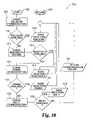
- FIG. 18is a flow diagram illustrating a technique for configuring the tracking device.
- FIG. 19is a flow diagram illustrating a technique for updating the status of the personal identification device of the tracking device.
- FIG. 20is a flow diagram illustrating a technique for detecting zone or region violations.
- FIG. 21is a flow diagram illustrating a technique for reducing errant location readings of the tracking device.
- FIG. 22is a flow diagram illustrating a technique the tracking device uses to receive incoming messages.
- FIG. 23is a flow diagram illustrating a technique the tracking device uses to send outgoing messages.
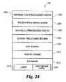
- FIG. 24is a diagrammatic view of a monitoring system according to one embodiment of the present invention.
- FIG. 25is a flow diagram illustrating a technique for processing incoming messages with the monitoring system.
- FIG. 26is a flow diagram illustrating a technique for validating incoming messages with the monitoring system.
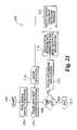
- FIG. 27is a flow diagram illustrating a technique for separating header and body information of the incoming messages with the monitoring system.
- FIG. 28is a flow diagram illustrating a technique for validating the version and message type of the incoming message.
- FIG. 29is a flow diagram illustrating a technique for processing rules with the monitoring system.
- FIG. 30is a flow diagram illustrating a technique for evaluating rules with the monitoring system.
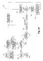
- FIG. 31is a flow diagram illustrating a technique for evaluating time based rules with the monitoring system.
- FIG. 32is a flow diagram illustrating a technique for evaluating exterior region rules with the monitoring system.
- FIG. 33is a flow diagram illustrating a technique for evaluating interior region rules with the monitoring system.
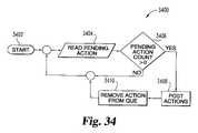
- FIG. 34is a flow diagram illustrating a technique for handling actions in the monitoring system.
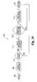
- FIG. 35is a flow diagram illustrating a technique for reducing the number of repeated violation alerts from the monitoring system.
- FIG. 36is a flow diagram illustrating a technique for processing actions with the monitoring system.
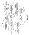
- FIG. 37is a flow diagram illustrating a technique for sending a message to an on-duty corrections officer.
- FIG. 38is a flow diagram illustrating a technique for checking for loss of communications with the tracking device.
- FIG. 39is a flow diagram illustrating a technique for checking for receipt of a message.
- FIG. 40is a flow diagram illustrating a technique for reevaluating the threat level of an open violation.
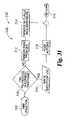
- FIG. 41is a flow diagram illustrating a technique for remotely resetting a tracking device.
- FIG. 42is a flow diagram illustrating a technique for improving location determination when a monitored individual is nearly motionless.
- System 100includes a personal tracking device or unit (PTU) 102 for tracking a monitored individual, a wireless telephone provider system 104 , a computer network 106 operatively coupled to the wireless provider system or network 104 , and monitoring system 108 operatively coupled to the computer network 106 .
- PTUpersonal tracking device or unit
- an administrative computer 110is operatively coupled to the monitoring system 108
- a law enforcement computer 112is operatively coupled to the monitoring system 108 through the computer network 106 .
- the administrative computer 110can be operatively coupled to the monitoring system 108 through the computer network 106 , and the law enforcement computer 112 can be directly coupled to the monitoring system 108 .
- the tracking device 102communicates with the monitoring system 108 and determines its location through wireless telephone antennas or cell phone towers 114 , which are operatively coupled to the wireless provider system 104 .
- portable devices 116communicate with the monitoring system 108 through the cell towers 114 .
- the portable devices 116can include, but are not limited to, both analog and digital cell phones, pagers, personal digital assistants (PDAs), a laptop computers and the like. In one embodiment, the portable devices 116 are cell phones.
- the portable devices 116include a portable law enforcement device 118 that is used by monitoring system 108 to alert law enforcement officials of violations and a victim or at risk individual device 120 that is used alert at risk individuals, such as a person with a restraining order, that a monitored person is in close proximity.
- tracking device 102incorporates portable device 116 .
- the monitoring system 108is used to track the location of monitored individuals and report to the law enforcement officials and/or potential victims any parole and/or restraining order violations.
- the monitored individualscan include, but are not limited to, parolees, house arrest detainees, persons whom have a restraining order placed against them, and other persons to whom the criminal legal system wishes to track. For example, when a parolee violates the location restrictions of their parole, monitoring system 108 determines that a violation has occurred and alerts law enforcement officials of the violation through law enforcement computer 112 and/or portable law enforcement device 118 .
- the monitoring system 108can alert an at risk individual through at risk individual device 120 that a monitored person has violated their restraining order and can give the location of the monitored person so that the at risk individual can take preventative measures to avoid the monitored person.
- Administrative computeris used to administer the monitoring system 108 and generate reports.
- the monitoring system 108includes a processor 122 and memory 124 .
- the monitoring system 108along with computers 110 and 112 can include personal computers, portable devices 116 , computer terminals, PDAs, and/or other types of devices generally known to those skilled in the art.
- the monitoring system 108is a personal computer or server encoded with software that performs the monitoring techniques as described below.
- the processor 122is used to control the operation of the monitoring system 108 .
- the processor 122may be comprised of one or more components.
- one or more componentsmay be located remotely relative to the others, or configured as a single unit.
- processor 122can be embodied in a form having more than one processing unit, such as a multi-processor configuration, and should be understood to collectively refer to such configurations as well as a single-processor-based arrangement.
- One or more components of the processor 122may be of electronic variety defining digital circuitry, analog circuitry, or both.
- Processor 122can be of a programmable variety responsive to software instructions, a hardwired state machine, or a combination of these.
- monitoring system 108can include a clock 126 for timing and tracking events. It should be understood that clock 126 can be hardware based and/or software based.
- Memory 124can include one or more types of solid state memory, magnetic memory, or optical memory, just to name a few.
- memory 124can include solid state electronic random access memory (RAM), sequential access memory (SAM) (such as first-in, first-out (FIFO) variety or last-in, first-out (LIFO) variety), programmable read-only memory (PROM), electronically programmable read only memory (EPROM), or electronically erasable programmable read only memory (EEPROM); an optical disk memory (such as a DVD or CD-ROM); a magnetically encoded hard disk, floppy disk, tape, or cartridge medium; or a combination of these memory types.
- RAMsolid state electronic random access memory
- SAMsequential access memory
- PROMprogrammable read-only memory
- EPROMelectronically programmable read only memory
- EEPROMelectronically erasable programmable read only memory
- an optical disk memorysuch as a DVD or CD-ROM
- the memory 124may be volatile, non-volatile, or a hybrid combination of volatile and non-volatile varieties, and memory 124 can be in the form of removable memory.
- memory 124can include removable memory 128 that can be in the form of a non-volatile electronic memory unit, optical memory disk (such as a DVD or CD ROM); a magnetically encoded hard disk, floppy disk, tape, or cartridge medium; or a combination of these or other removable memory types.
- Network 106can include the Internet, one or more other wide area networks (WAN), a local area network (LAN), a proprietary network such as provided by America Online, Inc., a combination of these, and/or other types of networks generally known to those skilled in the art. In one form of the present invention, the network 106 includes the Internet.
- the wireless telephone provider system 104includes both analog or digital cell phone systems, such as wireless telephone systems that use Code-Division Multiple Access (CDMA), Personal Communication Services (PCS) and other types of wireless telephone networks/services as generally know to those skilled in the art.
- the wireless system 104is operable to locate the portable devices 116 and transmit the location to the portable devices 116 .
- the location of portable devices 116can be determined through angle of arrival to towers 114 , time of arrival to towers 114 , through assisted GPS via satellite 130 , a combination of these, and in other manners as generally know to those skilled in the art.
- the location of portable devices 116is tracked by using a SNAPTRACK brand assisted-GPS system.
- a location tracking system 131is used to monitor the location of the tracking device and relay the location information to the monitoring system 108 .
- the location tracking system 131can be operated by a third party, such as by the wireless telephone provider. By having a third party determine the location of the tracking device 102 , a significant amount of overhead associated with determining the monitored person's location can be reduced.
- the size of the data packets with location information communicated from the location tracking system 103can be reduced and/or the intervals between transmission of location information can be adjusted based on a number of factors, including the current location of the monitored individual. As should be appreciated, reducing the amount of data communicated in such manners, reduces the communication costs associated with system 100 .
- the location tracking system 131is operatively coupled to and communicates through the wireless telephone provider system 104 and the network 106 .
- the location tracking system 131can be only operatively coupled to the wireless telephone provider system 104 or the network 106 .
- the location tracking system 114is integrated into the wireless telephone provider system 104 .
- Wireless telephone providerssuch as Nextel, offer location tracking services in which a company or some other organization can request the location of a cellular telephone, if so authorized. By bundling the location tracking service with the wireless communication service plan, a more favorable overall rate can be negotiated between the wireless telephone provider and the owners of the monitoring system 108 .
- the location informationcan be stored on the location tracking system 131 , and only a summary of the location information, such as an average location, or a sample of the location information can be transmitted to the monitoring system 108 , thereby reducing the overall data bandwidth used.
- the monitoring system 108places a request with the location tracking system 131 in order to receive the location of the tracking device 102 , and in another embodiment, the location tracking system 131 periodically sends or pushes the location information to the monitoring system 108 .
- the location tracking system 131can periodically send location information at a low rate, and the monitoring system 108 can request location information at a higher rate, when the monitored person is violating a rule. It is contemplated that in other embodiments a combination of requesting and pushing techniques can be used.
- the tracking device 102determines its location and changes the reporting rate for the location information based on where the tracking device 102 is located.
- the tracking device 102includes two components, a wearable transmitter or personal identification device (PID) 132 and monitored portable device 134 ( 116 ).
- the PID 132is wearable by the monitored person and periodically transmits a status signal to device 134 .
- PID 132is an ankle bracelet attached to the ankle of the monitored person and device 134 is a cellular telephone.
- PID 132 and device 134can be separate components or integrated into a single unit.
- PID 132 and device 134are operatively coupled to one another through a wireless connection.
- Wearable PID 132is operable to only transmit for a limited range. It should be appreciated that PID 132 and device 134 can be operatively coupled to one another using a radio frequency transmission protocol, such as using Bluetooth technology or IEEE 802.11.
- wearable PID 132includes an antenna 202 , a transmitter (or transceiver) portion 204 , a processor 206 , memory 208 and a clock 210 .
- the processor 206 , memory 208 and clock 210are similar to the ones described above.
- Transmitter portion 204 and antenna 202are used to transmit the status signal to device 134 .
- both PID 132 and device 134can be powered through a battery, fuel cell and/or in other generally known manners.
- PID 132includes a tamper evidence detector 212 for detecting the monitored person tampering with PID 132 in an attempt to remove the wearable PID 132 .
- the tamper evidence detector 212can include, but is not limited to, a thermal sensor for sensing body temperature and a wire though a strap that secures the wearable PID 132 to the monitored person.
- Portable device 134includes an antenna 214 , a transceiver 216 , a processor 218 , memory 220 , a clock 222 , and a motion detector or sensor 223 .
- Antenna 214 and transceiver 216are used for communicating with the wearable PID 132 and the cell towers 114 .
- Processor 218 , memory 220 and clock 222are similar to the ones described above.
- the motion sensor 223is used determine if the monitored individual is moving so that the portable device 134 can utilize a number energy conserving techniques when the individual is not in motion.
- the motion sensor 223is incorporated into the portable device 132 , but it should be recognized that the motion sensor 223 can be located elsewhere.
- the motion sensor 223 in a further embodimentis incorporated into the PID 132 , and in yet another embodiment, the motion sensor 223 is a separate unit worn by the individual.
- the motion sensor 223includes an off the shelf ball and cage type motion sensor.
- the motion sensor 223can include other types of motion sensors, such as accelerometers, gyroscopes and mercury switches, to name a few.
- monitored portable device 134can include a GPS receiver or chip set 224 .
- a technique according to one embodiment for transmitting the status of the monitored device 102is illustrated with flow diagram 300 in FIG. 3 .
- portable device 134determines its location through cell towers 114 and the wireless provider system 104 (i.e., enhanced 911 service).
- the monitored device 102is able to be tracked even when indoors. This improves the overall location determination efficiency.
- the monitored device 102is tracked using GPS and/or assisted GPS.
- Processor 218 of device 134stores its location in memory 220 .
- the wearable PID 132periodically transmits status information to device 134 .
- the wearable transmittertransits identification and status information to portable device 134 every five (5) seconds.
- device 134determines whether a signal has been received from PID 132 . If the status signal has not been received, the processor 218 determines whether a delay limit between signals has been reached.
- the wearable PID 132is given a specified period of time to communicate with the portable device 134 . This delay limit reduces the number of false alarms caused by conditions, such as radio interference or the monitored person being temporarily away from the portable device 134 .
- the delay time limitis fifteen (15) seconds. As should be appreciated, other time limits can be used, depending on operational conditions.
- processor 218 in the portable device 134continues to determine its current location in stage 302 . Otherwise, when the delay time limit has been reached in stage 306 , processor 218 transmits an encrypted alert message to monitoring system 108 in stage 308 .
- the alert messageis sent via the cell towers 114 of the wireless telephone network 104 and network 106 to the monitoring system 108 .
- the portable device 134encrypts the location data from stage 302 along with a portable device/monitored person identifier. By encrypting this information, the privacy of the persons tracked by system 108 is preserved even when transmitted across a publicly accessible networks 104 and 106 .
- the portable device identifieris used to identify the monitored person. In one form, this identifier is a unique serial number. It should be understood that other types of identifiers can be used to identify the monitored system.
- processor 218encrypts the location and identifier information using a two key or asymmetric encryption algorithm. Following stage 308 , the processor 218 of the portable device 116 continues to monitor its location in stage 302 and for a signal in stage 304 .
- the wearable PID 132periodically transmits a signal containing status information along with an identifier that identifies the wearable transmitter 134 .
- the unique identifiercan be a serial number or some other type of identifier as known by those skilled in the art.
- the identifier transmitted by the wearable PID 132is the same as the portable device identifier.
- the wearable transmitterpseudo-randomly changes the identifier at specified timer intervals in order to prevent tampering.
- the status and identifier informationis encrypted using an asymmetric encryption algorithm. It should be appreciated that other types of encryption algorithms can also be used.
- processor 218determines whether the signal contained the proper identifier. If not, processor 218 determines whether the delay time limit was reached in stage 306 , and when required, alerts the monitoring system 108 in stage 308 . If the portable device 134 determines that the proper identifier was received in stage 310 , processor 218 determines in stage 312 whether the status portion of the received signal indicates that the status of the wearable PID 132 is normal. The status signal from wearable PID 132 will not be normal or “OK” when the wearable PID 132 is not operating properly.
- the wearable PID 132sends a “tamper” status signal to the portable device 134 .
- the wearable PID 132sends a “low battery” signal when the charge of batteries in the wearable device 134 is low.
- the portable device 134sends an alert to the monitoring system 108 in stage 308 .
- the portable device 134can further send the status information from the wearable PID 132 to the monitoring system 108 in stage 308 .
- the portable PID 132 in stage 314determines whether the monitored person is away from a designated “home” location or zone.
- the portable PID 132 and monitoring system 108incorporates a variable transmission rate feature according to the present invention. Not only does this feature reduce communication traffic, this feature also reduces resource demands on the monitoring system 108 so that a larger number of persons can be monitored at the same time.
- the portable device 134reduces the number of location/status transmissions to the monitoring system 108 when the monitored person is at a “home” location, such as their home or place of work. This reduces the amount of redundant location information received and processed by the monitoring system 108 . When a monitored person is on the move, such as travelling away from their home, location information is sent to the monitoring system 108 at a higher rate.
- both portable device 134 and system 108are aware of when the transmission rate of location information is adjusted. This makes it more difficult for a monitored person to circumvent safety protocols in system 108 .
- one or more “home” locationsare preprogrammed in the portable device 134 and stored in memory 124 of the monitoring system 108 when the monitored person is initially registered with the system 108 .
- the portable device 134downloads one or more “home” locations periodically (such as every night) from the monitoring system 108 .
- the portable device 134dynamically creates a “home” location.
- the portable deviceWhen a person has not moved from a location for a specified period of time, the portable device sends a “home” location signal to the monitoring system 108 to alert the monitoring system 108 that the portable device 134 is going to increase the period between transmissions.
- the portable device 134sends a signal to the monitoring system 108 designating the current location as a “home” location and changes to a “home” location transmission mode.
- processor 218 in stage 318determines whether it is time to send the location information under “home” transmission mode.
- the portable PID 132sends its location every five minutes in the “home” transmission mode and every thirty seconds when not in the “home” transmission mode. It should be appreciated that other time intervals can be used.
- the portable device 134encrypts and sends to the monitoring system the portable device identifier along with the location information. In stage 316 , if the time interval between transmissions in the “home” transmission mode has not elapsed, the portable device 134 does not send location information to the monitoring system 108 and determines its current location in stage 302 .
- a technique for processing messages from monitored personsis illustrated with flow diagram 400 in FIG. 4 .
- the monitoring system 108monitors for messages from the network 106 , and the processor 122 of the monitoring system 108 determines in stage 404 whether a message has been received in stage 404 . If a message has not been received, processor 122 determines whether an allowable time between messages limit has been reached for any of the monitored persons. As discussed above, the time limit between message can be variable, depending on whether the monitored person is at a “home” location or not.
- the monitoring system 108maintains time limit and other information about the monitored persons in memory 124 .
- the information stored in memory 124can include the name of the monitored person, description, criminal record, home address, telephone number, place of work, work schedule, permitted locations of travel, restraining order information, time limits between messages information, last known location, identifier for the portable device 134 , historical travel information and the like.
- the information stored in memory 124is stored in a database.
- other types of data structurescan be used to store information in memory 124 .
- the monitoring system 108alerts officials of the violation.
- the alertcan contain the name of the monitored person, description and their last known location. It should be appreciated that the alert can contain additional information.
- the monitoring system 108sends the alert across the network 106 to the law enforcement computer 112 , and in one form, the monitoring system 108 sends an email containing the alert to the law enforcement computer 112 . In another form, an alert web page is displayed on the law enforcement computer 112 . Once the alert is received, law enforcement officials can be dispatched in order to find the monitored person. Alternatively or additionally, the monitoring system 108 can contact the closets available law enforcement official through portable law enforcement device 118 .
- the location of the law enforcement portable device 118is monitored in the same fashion as described above for the monitored person.
- Device 118periodically sends location and identification information to the monitoring system 108 via towers 114 .
- Processor 122stores in memory 124 the location of various law enforcement officers, and based on their location, monitoring system 108 contacts the closets law enforcement official via portable device 118 .
- the monitoring system 108can send to device 118 a voice message and/or text message (page) alerting the officer that a particular monitored person needs to be contacted or apprehended. Once alerted, law enforcement official can take appropriate action.
- both the law enforcement portable device 118 and portable device 134are operable to communicate directly with one another without the use of towers 114 .
- devices 118 and 134use a walkie-talkie type of communication, such as the NEXTEL DIRECT CONNECT® feature, to communicate with one another.
- a walkie-talkie type of communicationsuch as the NEXTEL DIRECT CONNECT® feature
- the law enforcement officialcan receive a text message that contains the direct connect and/or telephone number for the monitored person so as to eliminate the need for the official to look up the number for the monitored person.
- processor 122 of the monitoring system 108continues to monitor for messages in stage 402 .
- the monitoring system 108decrypts the message and records in memory 124 the identifier and location information contained in the message in stage 410 .
- system 108track the location of monitored individuals, such as parolees, system 108 further tracks the location of law officials via device 118 and at risk individuals, such as persons with restraining orders, via device 120 .
- monitoring system 108can update any changes to the designated “home” location and/or allowed time limits between messages.
- processor 122determines in stage 412 whether the message was from a monitored person. If not, processor 122 assumes that the message is from either a law enforcement official or an at risk person. At risk individuals, such as persons with retraining orders or domestic abuse safe houses, can register with the monitoring system 108 in order to prevent specific monitored persons from coming within a specified distance of the at risk individuals. For instance, a person with a restraining can register with system 108 to prevent a stalker from coming within 500 meters of them.
- the monitoring system 108determines if the monitored person is too close to the at risk person or within a “danger zone” with respect to the at risk person. If the at risk individual is not close to a specified or targeted monitored person, system 108 continues to monitored for messages in stage 402 . Otherwise, the monitoring system 108 in stage 416 alerts the at risk individual that the monitored person is close via device 120 .
- the monitoring system 108can send a text, voice and/or other type of message, which provides the name of the monitored individual, their location and direction of travel. As should be understood, the monitoring system 108 can supply other information. By alerting the at risk person of the close proximity of the monitored person, the at risk person can take appropriate actions to avoid the monitored individual.
- the monitoring system in stage 416sends a command over provider network 104 to the monitored portable device 134 of the targeted monitored individual so as to remove the “home” operational mode and/or increase the message update rate from device 134 .
- Thisimproves location determination accuracy when the need for accurate location information is the most critical.
- the monitoring system 108 in stage 416can alert officials in a manner similar to the one described above for stage 408 . After stage 416 , the monitoring system 108 continues to monitor for messages in stage 402 .
- processor 122 in stage 418determines whether the message contained a normal status update. As discussed above, device 134 sends an alert status message when for example the wearable PID 132 has been tampered with or portable device 134 did not receive a transmission from the wearable PID 132 within a specified period of time. If the message does not contain a normal status update in stage 418 , the monitoring system 108 alerts the law enforcement officials in stage 408 . The alert can contain a message on the particular problem experienced with the portable device 134 .
- the monitoring system 108When system 102 is operating normally, the monitoring system 108 receives a normal status message, and in stage 420 , processor 122 determines whether the monitored person is far enough away from the at risk or restricted person. When the monitored person is too close to a particular at risk person, the monitoring system 108 alerts the at risk person in stage 416 . As mentioned above, the monitoring system 108 in stage 416 can further alert officials of the violation. As should be appreciated, not all monitored persons may be prohibited from coming into close proximity of an at risk persons. For instance, a home detainee may not have a restraining order against them.
- the monitoring system 108stores in memory 124 the locations or zone in which the monitored person is allowed to travel. When in stage 420 the monitored person is not restricted from particular at risk individuals or is far from any restricted individuals, the monitoring system 108 determines in stage 422 whether the monitored person is outside the zone in which they are allowed to travel. If the monitored person is outside the zone, the monitoring system 108 alerts the appropriate officials in stage 408 . Otherwise, the monitoring system 108 continues to monitor for messages in stage 402 .
- the portable device 116 of the personal tracking device 102can include many types of devices, such as cellular telephones and/or PDA's.
- portable device 116 aincludes a cellular or mobile telephone 502 .
- the mobile telephone 502is operatively coupled to a Radio Frequency Receiver Module (RFRM) 504 that is operable to process communications with the PID 132 to form a personal tracking device 102 a, as is shown in FIG. 7 .
- the mobile telephone 502includes Java 2 Platform Micro Edition (J2ME/MIDP) technology running on a Nextel i58 or i88 brand GPS enabled mobile telephone.
- J2ME/MIDPJava 2 Platform Micro Edition
- mobile telephone 502can include other types of mobile telephones and can be programmed in other manners.
- other types of devices portable devicescan be utilized.
- the receiver module 504has a connector 506 that plugs into an accessory/data cable connector 508 in the mobile telephone 502 .
- the receiver module 504is only able to receive communications from the PID 132 , but it is contemplated that in other embodiments the receiver module 132 can send and receive two-way communications with the PID 132 .
- the connector 506is operatively coupled to a circuit board 510 with a processor 512 .
- the motion sensor 223 of FIG. 2is mounted to the circuit board 510 and operatively coupled to the processor 512 so that the receiver module 504 is able to detect motion of the monitored individual.
- the processor 512is operatively coupled to an antenna 514 , and the antenna 514 is configured to receive and transmit messages with the PID 132 . After processing the message, the processor 512 sends the message to the mobile telephone 502 , which has a program that further processes the message.
- the antenna 514is in the form of a coil 514 so as to minimize the size of the receiver module 504 .
- the components of the receiver module 504are contained in a housing 516 .
- the receiver module 504 in the illustrated embodimentis powered by the mobile telephone 502 . Nonetheless, it should be understood that in other embodiments the receiver module 504 can be self-powered, such as with a battery and/or a fuel cell.
- the processor 512is configured to process messages, such as status messages received from the PID 132 via the antenna 514 .
- the mobile telephone 502in one embodiment is configured to turn on the receiver module 504 only on an as needed basis. For instance, the mobile telephone 502 can energize the receiver module 504 just before a message is suppose to be received from the PID 132 and can place the receiver module 504 in a sleep mode after the message is received.
- the receiver module 504is configured to power down and/or reset the mobile telephone 502 upon receipt of a reset command from the monitoring system 108 . With this capability to remotely reset the mobile telephone 502 , the monitoring system 108 is able to remotely address software problems on the mobile telephone 502 by reinitializing its software.
- the system 100allows monitored individuals to directly communicate with the appropriate officials, such as corrections officers, as well as others.
- the system 100allows monitored individuals to receive messages automatically generated by the monitoring system 108 in a number of formats and acknowledge the message without requiring additional human input.
- the mobile telephone 502includes a number of input/output devices, such as a display 518 , a keypad 520 , a microphone 522 and a speaker. Text messages, pictures, movies and other visual media can be displayed on the display 518 .
- the monitored individualcan receive text instructions via the display 518 .
- the monitored individualcan respond to messages via the keypad 520 .
- the keypad 520includes one or more buttons, such as menu navigation buttons 526 , a menu button 528 , alphanumeric buttons 530 , a walkie-talkie button 532 and the like.
- the monitored individualcan verbally communicate with the corrections officer through the microphone 522 and speaker 524 .
- the mobile telephone 502can incorporate other devices, for example a camera.
- the mobile telephone 502 , the receiver module 504 , and/or the PID 132can be integrated together to form a single unit.
- FIG. 8illustrates a portable device 116 b according to another embodiment of the present invention.
- Portable device 116 bincludes mobile telephone 502 that is configured to communicate directly with the PID 132 to from a personal tracking device 102 b .
- the mobile telephone 802communicates with PID 132 via the Bluetooth communication protocol. It should be appreciated, however, that the mobile telephone 502 can communicate in other manners, such as via a radio frequency (RF) for commercial PID protocol, RFID, 802.11, Aura magnetic communications, and/or ZigBee protocol, to name a few.
- RFradio frequency
- FIG. 9illustrates a personal tracking system 102 c that includes a base unit or station 902 that wirelessly communicates with PID 132 .
- the PID 132is operable to automatically switch communications from the mobile telephone 502 to the base unit 902 and back. Communications can be diverted to the base unit 902 in environments where cellular communication is not allowed or unavailable.
- the PID 132can be configured to dynamically communicate with the base unit 902 in the event the mobile telephone 502 cannot be located. For example, when the mobile telephone 502 is out of range of cell phone towers 114 , the PID 132 is operable to send communications to the monitoring system 108 through the base unit 902 , which can have a wired connection to the network 102 .
- the base unit 902can communicate with the network 106 in a number of manners.
- the base unit 902can communicate using a dialup connection, Bluetooth, ZigBee, Aura magnetic communications (Aura Communications) and/or broadband connectivity, to name a few.
- the use of the PID 132is optional in some situations such that the mobile telephone 502 is used solely to track and communicate with a person. For example, police officers with law enforcement devices 118 and at risk individuals with device 120 do not need PID's 132 . Nonetheless, it may be desirable that these individuals maintain constant contact with the monitoring system 108 in case an event that requires their attention arises.
- one or more base units 902can be installed so as to maintain communications between the at risk individual device 120 and the monitoring system 108 .
- one or more base units 902can be installed in a halfway house type environment so as to allow the batteries on the mobile telephones 502 of parolees to recharge as well as reduce the communication load on the cellular telephone network. It should recognized that multiple PID's 132 and/or mobile telephones 502 can communicate with a single base unit 502 at the same time.
- the mobile telephone 502may be out of range and/or located near a base unit 902 such that communications can be switched between the cell towers 114 to the base unit 902 and/or some other means for communicating with the network 106 , such as a wireless router.
- a technique for automatically switching communication channels according to one embodiment of the present inventionwill now be described with reference to flowchart 1000 in FIG. 10 . As will be appreciated from the description below, this technique illustrated in FIG. 10 can be used by the PID 132 and/or the mobile telephone 502 in order to switch communication channels.
- the PID 132can switch communications from the mobile telephone 502 to the base unit 902 when the mobile telephone 502 is being recharged or repaired.
- the mobile telephone 502can switch communication channels from the cell towers 114 to the base station 902 when the monitored person is for example at home or at a location that is out of range from the cell towers 114 .
- the technique illustrated in flowchart 1000will be primarily described with reference to the PID 132 , but it is contemplated that the mobile telephone 502 can also use this technique.
- the PID 132After initiating the routine in stage 1002 , the PID 132 checks to see if cellular communication is available in stage 1004 . In one form, the PID 132 in stage 1004 checks to see if the PID 132 receives an acknowledgement or status message from the mobile telephone 502 is received. The status message can be sent periodically from the mobile telephone 502 and/or in reply to a previous message from the PID 132 . So for instance, if the PID 132 does not receive a status message from the mobile telephone 502 , the PID 132 considers cellular communication unavailable.
- the mobile telephone 502 in the status messagefurther supplies the signal strength for cellular communications, and below a specific signal strength threshold, the PID 132 considers cellular communication unavailable.
- the PID 132in one embodiment also determines its location relative to a known location of the base station 902 . If the PID 132 is in close proximity to the base station 902 , the mobile telephone 502 considers the area a cellular telephone communication drop-out area in which communication should be switched to the base station 902 . For instance, when the signal strength from the base station 902 is as strong as that of the cellular signal strength reported in the status message from the mobile telephone 502 , the PID 132 considers that cellular communication is not available.
- stage 1006if the cellular communication is available, the PID 132 sends the data through the wireless provider telephone system 104 in stage 1008 , via the mobile telephone 502 .
- the mobile telephone 502continues using the technique.
- the cellular telephone 502checks to see if Bluetooth communication is available with another device, such as base station 902 , in stage 1012 . It should be appreciated, however, that the PID 132 can establish wireless communication to other types of devices besides the base station 902 . If Bluetooth communication is available in stage 1014 , the PID 132 sends the data via the Bluetooth standard in stage 1016 . When Bluetooth is not available in stage 1014 , the PID 132 checks to see if ZigBee communication is available in stage 1018 . The PID 132 sends data through the ZigBee communication protocol to the desired device, such as base station 902 , when ZigBee communication is available in stage 1020 .
- the PID 132communicates with the base station 902 via ZigBee. Otherwise, in stage 1024 , the PID 132 checks whether or not 802.11 communication is available. When in stage 1026 , 802.11 communication is available, the PID 132 sends the data through the 802.11 connection in stage 1028 . Otherwise, in stage 1030 , the thread or subroutine running the technique returns a communication failure report to the PID 132 in stage 1030 .
- the above-described techniquecan incorporate other types of devices for communicating, such as wireless routers, infrared ports or computer cables.
- the communicationscan be detected in a different order. For example, ZigBee communications can be checked before checking the availability of Bluetooth communications. As should be appreciated, with the above-described technique, the risk of communication failure is reduced.
- the personal tracking device 102Due to the critical nature of tracking monitored persons, such as criminals, it is desirable that the personal tracking device 102 has a low failure rate.
- a technique for operating the personal tracking device 102will be described with reference to flowchart 1100 in FIG. 11 .
- two programs or threadsrun at the same time on the processor 218 of the mobile device 116 , a primary program and a backup program. If the primary program fails, then the backup takes over so as to become the primary program, and the now primary program restarts the previously failed primary program. It is contemplated that in other embodiments a similar technique can be used in the processor 206 of the PID 132 .
- both programscheck the status of the other via a heartbeat. If the other program is running, the program continues checking the status of the other program in stage 1102 . Otherwise, if the failed program in stage 1106 was the primary program, the backup program takes over operation of the tracking device 102 and acts as the primary program before reinitializing the failed program in stage 1110 . When the backup program fails, the primary program restarts the backup program in stage 1110 .
- the personal tracking device 102can be controlled via software, hardware, a combination thereof and/or in other generally known manners.
- the illustrated techniquewill be described with reference to software, but it should be appreciated that the technique can be accomplished in other manners.
- the personal tracking device 102has one or more J2ME based applications or threads running on its processor 218 .
- the below discussed techniqueswill be described with reference to a mobile telephone 502 , which is J2ME capable, that is used in conjunction with a PID 132 . Nevertheless, it should be appreciated that other types of tracking devices 102 can utilize these techniques.
- FIG. 12includes a flow chart 1200 that illustrates a technique for initializing a main or PID tracker application that is responsible for starting a number of threads on the processor 218 of the tracking device 102 .
- the tracking device 102can include two or more PID tracker applications, a primary and a backup, that track the operational status of the other PID tracker programs in order to back up the primary application, if it should fail.
- the techniques for operating the personal tracking device 102will be described with reference to a single PID tracker application, but it should be understood from the discussion above that more than one PID tracker application can run on the personal tracking device 102 .
- Flowchart 1200 in FIG. 12illustrates a technique for initializing the PID tracker application on the portable tracking device 102 .
- a J2ME telephonesuch as a Motorola brand GPS enabled cellular telephone
- a start-up applicationis initiated to start the PID tracker application, for example, by selecting the “Java Apps” menu item on a Motorola i-58 or i-88 brand telephone. It nonetheless should be appreciated that the application can be initiated in other manners such as by being automatically started when the tracking device 102 configured or when simply turned on.
- the start-up application in stage 1204sets the status of the PID tracker application in memory 220 to “not paused.”
- the operating system on J2ME type telephonesis able to pause the operation of specific applications or threads in the processor 218 so as to not interfere with the operation of the telephone. For example, when a call or text message is received, the operating system on the mobile telephone 502 pauses selected applications so as to allow the receipt of the telephone call or the text message.
- the start-up applicationdetermines if the PID tracker application is running on the processor 218 . If the PID tracker application is running in stage 1208 , the display 518 on the mobile telephone 502 displays a current display screen, which is whatever was previously shown on the display 518 .
- the PID tracker applicationWhen the PID tracker application is not running in stage 1206 , the PID tracker application via the start-up program initializes and then executes a number of threads on the processor 218 of the portable device 116 .
- the PID tracker applicationis designed to run without user interaction and does not allow any other functions on the mobile telephone 502 with the exception of receiving incoming communications, such as a direct connect message, a text message or telephone call, to name a few.
- the PID tracker application in stage 1210starts a number of threads on the processor 218 , including a PID handler thread, a status handler thread, a location or GPS handler thread, and a server handler thread.
- the PID handler threadis responsible for handling communications with the PID 132 .
- the PID handler threadis responsible for all communications between the mobile telephone 502 and the receiver module 504 that is attached the mobile telephone 502 .
- the receiver module 504transfers an encrypted message from the PID 132 to the memory 220 of the mobile telephone 502 , which decrypts the message and updates PID status information with status handler thread.
- the status handler threadreceives GPS and PID status information and creates a status message, which is stored in memory 220 . This status message is usually sent to the monitoring system 108 via the server handler thread at every report interval (RI).
- Each zonecan have its own specified reporting interval, and as a result, the reporting interval of status messages can vary depending on the location of the monitored individual. However, if a violation occurs, the violation may be reported sooner than the designated report interval.
- the GPS threadis responsible for handling the location tracking information. On receipt of GPS and/or other location information from the GPS receiver 224 , the status handler compares the GPS coordinates to each zone that is configured on the personal tracking device 102 , and if a zone breach is detected, a notification is issued.
- the GPS threadwill be described with reference to a GPS system, it should be appreciated that other location determination systems and techniques can be used. In one embodiment, such as with the mobile telephone 502 of FIG.
- the GPS threadis responsible for handling all interactions with a GPS chip set 224 on the mobile telephone 502 , if so equipped.
- the GPS threaduses Nextel's Position Applications Program Interface (API) designed for use with J2ME. Nevertheless, the GPS thread can be configured for use with the other types of systems.
- APINextel's Position Applications Program Interface
- the GPS threadUpon a successful GPS fix, the GPS thread will gather location parameters and pass them to the status handler thread, which in turn generates a status message that is sent by the server handler thread to the monitoring system 108 .
- the server handler thread responsibilitiesgenerally include all interactions with the monitoring system 108 , such as sending and receiving messages from the wireless network 104 .
- stage 1210After the PID tracker application initializes and executes the threads in stage 1210 , a main display is shown on the display 518 of the mobile telephone 502 in stage 1212 , and the PID tracker application is set to run in stage 1214 . In stage 1216 , the PID tracker application continues to operate.
- the tracking device 102runs one or more routines that manage the communications so that these communications do not interfere status and location messages sent to the monitoring system 108 .
- routinesthat manage the communications so that these communications do not interfere status and location messages sent to the monitoring system 108 .
- the operating system in the mobile telephone 502calls the pause routine of the PID tracker application.
- the pause routinepauses the processing of selected threads on the processor 218 ; while at the same time allows the processing of other threads to continue.
- the pause routinetemporarily halts all threads that might effect communication.
- the pause routinein one particular embodiment pauses operation of the server handler thread during communications; while at the same time permits continued operation of the PID handler, GPS handler and status handler threads on the processor 218 of the portable device 116 .
- the entire PID tracker applicationis paused during communications. It should be appreciated that other combinations of threads can be paused, during communications or during other activities on the tracking device 102 .
- the PID tracker applicationWhen the pause routine is called, the PID tracker application will start a background thread that is set to ask the operating system to resume the paused thread to the foreground periodically. This allows the PID tracker application to become the foreground application when the communication has ended.
- a technique for pausing and resuming threads on the tracking device 102is illustrated in flowchart 1300 in FIG. 13 .
- the pause routinewaits a period of time in stage 1310 before determining if the main display is shown in the display 518 in stage 1312 . If the main display is not shown in stage 1312 , the pause routine places a request with the operating system in stage 1314 to ask for the application to be resumed, and thereafter continues to check to see if the communication has ended in stage 1308 . In stage 1314 , the pause routine makes a resume request call to the J2ME operating system so as to request that the PID tracker application be placed into the foreground.
- the main or PID tracker applicationwill be placed at the top of the Z order. However, if the resume request call is not honored, such as when a telephone call has not ended, the operating system ignores the request.
- the main displayis shown in stage 1312
- the PID tracker application or threadis set to “not paused” in stage 1316 , and the processor 218 runs the now active thread in stage 1318 .
- the pause routineis exited in stage 1318 .
- the PID tracker applicationallows tracking device 102 to track the monitored individual and communications with the monitored individual at the same time. This gives corrections officers as well as other officials the ability to monitor and instantaneously communicate with monitored individuals, which can facilitate quicker resolution of actual or potential problems.
- the PID tracker applicationis designed to function on the tracking device 102 without user interaction so that the monitored individual is not able to circumvent or exit the PID tracker application. Occasionally, a service technician might need to access certain features or information concerning the tracking device 102 or may even to exit the PID tracker application entirely.
- the PID tracker applicationin one embodiment can be configured to use secret key combinations on the keypad 520 to allow the view of specific menu options. When the specific key combination is entered on the keypad 520 , the PID tracker application can display the information on the display 518 and/or perform the actions listed below in Table 1. In addition to the secret key combinations, the PID tracker application in another embodiment requires a password before the below menu options can be accessed.
- these secret keyscan be eliminated or limited in number so as to reduce the risk of the monitored individual gaining access to the PID tracker application. It is contemplated that in still yet another embodiment the tracking device 102 is configured to alert a corrections officer if keys on the keypad 520 are being pressed in a manner so as to indicated that the monitored individual is attempting to gain access to the PID tracker application.
- a techniciancan shutdown or exit the PID tracker application by pressing a specific key combination of the keypad 520 .
- a shutdown procedureis entered that terminates all running threads by calling their shutdown routines. These routines toggle a Boolean exit variable in memory 220 of the portable device 116 to “TRUE”. Each thread is cycling continuously, but will terminate the cycle when its exit variable is set to true.
- flowchart 1400 in FIG. 14illustrates such a technique that can be used to shut down the individual threads.
- a technique that the GPS handler thread uses to detect the position of one or more monitored individualswill now be described with reference to flowchart 1500 in FIG. 15 .
- selected stages of the technique illustrated in FIG. 15can be modified in other embodiments.
- the processor 218determines whether or not the GPS handler thread should shut down in stages 1504 .
- the time to exit variable in memory 220 of the portable device 116is set to true in order to shutdown the active threads. If in stage 1504 the exit thread is true, then the GPS handler thread shuts down or exits in stage 1506 .
- the GPS handler threadis responsible for handling all interactions with a GPS chip set or receiver 224 on the tracking device 102 .
- the GPS handleris responsible for interacting with the GPS chip set 224 on a GPS enabled telephone 502 .
- the GPS threaduses Nextel's position API designed for use with J2ME. Upon a successful GPS fix, the GPS handler thread gathers location parameters and passes them to the status handler thread.
- the processor 218 via the GPS handler threadestablishes connection with the GPS chip 224 in stage 1508 .
- the personal tracking device 102is designed to conserve battery power as much as possible, thereby allowing participants to be mobile for up to a day or more before requiring recharging of the tracking device 102 .
- the GPS handler threadis configured conserve energy used by the GPS chip 224 .
- the GPS chip 224 on the tracking device 102includes a delay feature in which the GPS chip 224 can use extra attempts to acquire a location fix.
- the delayis set to high so as to allow the GPS chip 224 greater time to acquire the current location of the tracking device 102 .
- a high delayis set, more requests are made over a longer period of time in order to acquire the current location. Since the GPS chip 224 is active for a longer period of time, this high delay results in greater power consumption in the tracking device 102 .
- the delay for the GPS chip 224is set to low when the tracking device 102 does not experience difficulty in acquiring its location. When a low delay is used, the fix must be acquired over a shorter period of time, resulting in the GPS chip 224 being powered for a shorter time period.
- the processor 218 via the GPS handler threaddetermines if the connection established with the GPS chip 224 in stage 1508 is acceptable.
- a GPS fixis determine to be a valid response from the GPS chip 224 when the GPS API returns a “POSITION_RESPONSE_OK” value.
- the status of the connectioncan be determined differently in other embodiments. If the position response is not acceptable (i.e., not “OK”), the GPS handler sets the delay for the GPS chip 224 to “high” in stage 1512 . As mentioned above, this high delay allows the GPS chip 224 greater time in order to determine a location fix.
- the GPS handler threadAfter the delay is set to high in stage 1512 , the connection to the GPS chip 224 is closed in stage 1514 , and GPS handler thread proceeds to stage 1504 .
- the GPS handler threadacquires the position information (i.e., latitude and longitude) from the GPS chip 224 in stage 1516 .
- the GPS handler threaddetermines whether the returned position values are valid. For example, in one embodiment, a returned position value of “null” would be considered invalid.
- the GPS handler threadsets the chip delay to high in stage 1512 and then proceeds to stage 1514 where the connection to the GPS chip is closed.
- the GPS handler threadnotifies the status handler thread of a GPS position fix and stores the position, such as the latitude and longitude, in memory 220 in stage 1520 . Since the GPS handler thread was able to acquire a valid position in stage 1520 , the GPS handler thread sets the GPS delay to low in stage 1522 in order to conserve power. After lowering the GPS delay in stage 1522 , the GPS handler thread in stage 1514 closes the connection to the GPS chip 224 , and the technique continues until shutdown (stage 1504 ). By adjusting the GPS delay, the technique illustrated with flow chart 1500 in FIG. 15 extends the time between recharging and/or refueling of the tracking device 102 .
- the tracking device 102monitors the status of the PID 132 .
- the PID 132is monitored in order to detect a number of conditions, such as PID tampering or low battery conditions.
- the PID handler threadmonitors and controls communications with the PID 132 .
- the PID handler threadis responsible for all communications between the mobile telephone 502 (J2ME application), and the receiver module 504 that communicates with the PID 132 . It should also be appreciated that the PID handler thread can be configured to directly communicate with the PID 132 , and not via the receiver module 504 , in other embodiments.
- the PID handler thread in other embodimentsis responsible for directly communicating with the PID 132 , such as illustrated in FIG. 8 ( FIG. 8 ). Nevertheless, it is contemplated that PID handler thread can be used in other types of configurations of the tracking device 102 .
- the receiver module 504transfers encrypted messages from the PID 132 to the portable device 116 a .
- the portable device 116 asuch as mobile telephone 502 , decrypts the information and updates the information with the status handler thread.
- interaction between the PID handler thread and the receiver module 504is performed by opening a serial connection with the connector 506 of the mobile telephone 502 .
- the mobile telephone 502communicates with the receiver module 504 via an RS-232 connection.
- the receiver module 504can be connected to the portable devices 116 in other manners generally known to those skilled in the art, such as via a USB or a parallel connection, to name a few.
- the PID handlerlooks for incoming information from the PID 132 .
- messages between the PID handler and the receiver moduleare communicated via ASCII messages.
- each messagesis framed with a leading, start of text (STX) ASCII character, and trailing end of text (ETX) ASCII character.
- STXstart of text
- ETXtrailing end of text
- Table 2below provides examples of some types of messages that are communicated in one embodiment.
- a valid PIDencrypts the message, must be decrypted and status issued.
- the messageincludes a PID identification number.
- STX-data bytes (PID ID, data)-ETX C Charge StateIndicates the charge state of the battery in the PID. Sent from the PID handler.
- Charge state messagecan be sent from receiver module to PID handler whenever battery voltage changes by 0.1 volts consistently.
- DShow Data Sent by the PID handler. Shows data on laptop monitoring pin.
- E Error Message Sent by PID handler. Requests error messages and codes be sent as they occur from now on (defaultoff). The receiver module sends the error message when received from the PID. Typically, the second byte is the error code. This code is passed back to the monitoring system.
- F Signal Strength PID handlerrequests signal strength of PID's transmissions or the PID requests the signal strength for communications with the monitoring system (cell phone signal strength).
- G InputSend receiver module's input current measurement.
- an error code of 3indicates that the battery in the ankle bracelet is low, or a value of 8 indicates that the strap has been cut or removed.
- An error code value of zeroindicates no error has occurred.
- other numbering schemescan be used to indicate errors in the PID 132 and/or the receiver module 504 .
- the PID handler threadis able to understand, decrypt, see and send a single variable describing the full condition of the PID 132 . Reducing the amount of data transmitted and processed, improves the overall energy efficiency of the tracking device 102 , which in turn increases the time between recharges and/or refueling of the PID 132 and the portable device 102 .
- the receiver module 504is periodically energized and de-energized. The energization of the receiver module 504 coincides with the expected reception time of messages from the PID 132 .
- the PID 132sends status messages in a periodic manner, and in another form, the PID 132 sends messages in a pseudo-random fashion. It is contemplated that the PID 132 can send messages in other manners.
- a serial connectionis opened by the PID handler on the connector 506 of the mobile telephone 502 .
- the PID handler threaduses in processing communications with the PID 132 to process communications with the PID 132 will now be described with reference to flowchart 1600 in FIG. 16 .
- the PID handlerwaits until the next wake-up time for the receiver module 504 in stage 1604 .
- the receiver module 504is placed in a sleep state in order to conserve energy in the tracking device 102 .
- the PID 132is periodically or in a pseudo-random fashion energized and de-energized in order to conserve energy.
- the PID handlerwakes up or energizes the receiver module 504 when needed, for example, just before the next message from the PID 132 is expected to be received.
- the receiver module 504can include an internal timer in which the receiver module 504 wakes itself up.
- the PID handlerkeeps an internal timer and schedules communications at the time the receiver module 504 is expected to be awake.
- the PID handler threaddetermines whether or not the thread is being shut down, as was described above with reference to FIG. 14 . If the shut down variable in memory 220 is true, the PID handler thread shuts down in stage 1610 . Otherwise, the PID handler thread in stage 1610 determines if a connection has been established with the receiver module 504 . When a connection has not been established, the PID handler thread establishes a connection with the receiver module 502 in stage 1612 .
- the mobile telephone 502 via the PID handler threadin one embodiment establishes a serial connection with the receiver module 504 , but it should be appreciated that a connection can be established in other manners. If the PID handler is unable to establish a connection with the receiver module 504 in stage 1612 , the PID handler notes the exception in memory 220 and closes the connection in stage 1614 . The exception noted in memory 220 is later used by the status handler thread in order to generate error message. Upon closing the connection with the receiver module 504 , the PID handler waits until the next receiver module wake-up time before proceeding in stage 1604 .
- the PID handlerpauses or waits for the receipt of data from the receiver module 504 in stage 1616 .
- the processor 218 of the portable device 116 via the PID handlerreads the incoming data from the receiver module 504 .
- the PID handler threadattempts to read the serial data one byte at a time, initially looking for the start of text byte. Once the start of text (STX) byte is received, all bytes received thereafter until receipt of the end of text (ETX) byte is stored in a byte array in memory 220 for processing.
- the processor 218 of the portable device 116decodes the message in stage 1620 .
- the receiver module 504can send a number of messages to the mobile telephone 504 .
- the PID handlerdecodes the type of message by the command character in the message. For instance, if the message after the start of text byte contains the “A” character, the PID handler determines the message to be an acknowledgement message and proceeds accordingly.
- the PID handlerAfter decoding the message in stage 1620 , the PID handler determines the source of the message in stage 1622 and processes the message accordingly. If the message concerns the receiver module 504 , such as a firmware ID message (H) or a hardware ID message (I), the PID handler in stage 1624 processes the receiver module message in stage 1624 . After processing the message in stage 1624 , the PID handler sets up the next wake-up time for the receiver module 504 in stage 1626 so that the receiver module 504 is awake when the next message is expected to be received from the PID 132 . As noted above, the PID 132 can transmit its messages in a periodic and/or pseudo-random basis.
- the PID handlersets the wake-up time of the receiver module 504 to be at or before the next wake-up time for the PID so that the receiver module 504 is able to receive data from the PID 132 , while at the same time minimizing the amount of energy consumed.
- the PID handler in stage 1628decrypts the message from the PID 132 .
- the message from the PID 132can include a unique PID identification number as well as status information that alerts the PID handler thread to any problems with the PID 132 .
- the PID handler in stage 1630notifies the status handler of the information, such as the error code, and subsequently, sets the next wake-up time for the receiver module 504 in stage 1626 .
- the PID handlercloses the connection with the receiver module 504 in stage 1614 .
- the PID handler threadcontinues the routine until the thread is shut down in stage 1606 .
- a map 1700 in FIG. 17illustrates a number of different types of zones that the monitoring system 108 uses in monitoring an individual. It should be noted that the map 1700 shown in FIG. 17 is only an example, and it should be appreciated that other different types of zone combinations and/or areas can be used. Although the example in FIG. 17 will be described with reference to a single monitored individual, the monitoring system 108 can also specify regions for groups of individuals. For instance, the monitoring system 108 can specify that a group parolees with a history of violent crimes can be prohibited from entering gun shops. In the illustrated example, a monitored individual is on a work-release program.
- the terms of the monitored individual's paroleallow the monitored individual to live at home 1702 , and at certain times, the monitored individual is allowed to travel to and from work 1704 along roads 1706 and the like. Another term of the monitored person's parole requires that the individual stay a specified distance from schools 1708 .
- the monitoring system 100utilizes a number of different types of zones or regions for monitoring the position of an individual. As should be appreciated, these zones are not limited to specific buildings and/or geographic features. As shown around the home 1702 and the work area 1704 , the monitored area can include interior regions or inclusion zones 1710 in which the monitored individual must stay. Furthermore, the monitored person can have exterior regions or exclusion zones 1712 in which the monitored person is prohibited from entering. The regions 1710 , 1712 can be stationary (static) and/or can be dynamic so as to change over time. For example, the location of an exterior region 1712 can vary over time as the person with a restraining (device 120 ) goes about their daily routine.
- the interior regions 1710can, if so wished, be subdivided into warm interior regions 1714 and hot interior regions 1716 .
- the tracking device 102When inside the warm interior regions 1714 , the tracking device 102 only reports the position and status information (if so desired) at a low rate. When in the hot interior region, the device reports location as well as status information, if so desired, at a higher rate.
- the exterior regions 1712can be subdivided into warm exterior regions 1718 and hot exterior regions 1720 .
- an alarm sounds on the tracking device 102in one embodiment.
- the reporting rateincreases as well as other alerts can be provided.
- the interior 1710 and the exterior 1712 regionscan include tepid regions that have a lower priority than the warm and hot regions.
- the specified interior 1710 and/or exterior 1712 regions for the monitored individualcan also include a series of geo-routes 1722 along which the monitored individual can travel. These geo-routes 1722 can have designated time periods of when they are effective, like the other regions.
- the geo-routes 1722include a series of interior regions 1710 that generally coincide with the shape of the road 1706 . It should be appreciated, however, that the geo-route 1722 can be defined by exterior regions 1712 , or a combination of exterior and interior regions.
- a violationcan for example cause one or more of the following events: a change in the reporting rate, a change in the amount of data transmitted in a message, an audible alert sound and/or a visual alert can be displayed, to name a few.
- the zones in FIG. 17have a square or rectangular shape, that is, they are non-circular.
- the computing power required to calculate the latitude and longitude of the rectangular zoneis significantly reduced as compared to computing the latitudes and longitudes of a circular zone.
- the use of rectangular shaped zonesis especially helpful with portable devices 116 , such as mobile telephones 502 , which usually have limited computing power.
- the zones described belowhave a rectangular shape, it is contemplated that the zones in others embodiments can have other polygonal shapes. Moreover, due to the curvature of the Earth, it should be appreciated that the boundaries of the zones may be slightly bowed.
- the monitoring system 108in one embodiment sends to the tracking device 102 upper left 1724 (northwest) and lower right 1726 (southeast) latitude/longitude coordinates. In addition to sending the upper left 1724 and lower right 1726 coordinates, the monitoring system 108 sends one or more identifiers that identify the zone type (i.e., interior, exterior, tepid, warm, and hot). Further, the monitoring system 108 can specify the reporting interval for the specific zone, if needed. In one embodiment, if the reporting interval is not set, the tracking device 102 uses a default reporting interval, which can be set when the tracking device is configured.
- the tracking device 102performs a one-time calculation for the four (4) boundary coordinates that define the zone and store the boundary coordinates in memory 220 along with the other information pertaining to the zone. For instance, the tracking device 102 determines lower left coordinates 1728 (southwest) of a zone by combining the longitude of the upper left coordinate 1724 with the latitude of the lower right coordinate 1726 . Similarly, the tracking device 102 calculates upper right coordinates 1730 of a zone by combining the latitude of the upper left coordinate 1724 with the longitude of the lower right coordinate 1726 . To specify a warm or tepid region, the monitoring system 108 sends a latitude perimeter distance 1732 and a longitude perimeter distance 1734 for the desired warm or tepid region.
- the tracking device 102determines the warm or tepid regions by adding or subtracting the perimeter distances 1732 , 1734 , depending on the region type. Nevertheless, it should be appreciated that boundary coordinates for the rectangular zone can be communicated and/or calculated in other manners. For instance, the monitoring system 108 can send to the tracking device 102 a center coordinate along with the length and width of the rectangular zone. To update the zone coordinates, the monitoring system 108 simply transmits the new coordinates to the tracking device 102 , which in turn updates the boundary coordinates in memory 220 .
- the personal tracking device 102is able to handle a maximum number of interior and/or exterior zones, such as four (4) zones or two-hundred and fifty-five (255) zones. In another embodiment, the number of zones is not limited to a specific maximum number. Even when the number of zones are fixed, the zones can be changed as the tracking device 102 is running, thereby providing a virtual unlimited number of zones available to monitor an individual.
- the zonescan be defined in the form of other polygonal shapes by the tracking device 102 receiving two or more coordinates that define the polygonal shape.
- the monitoring system 108sends the coordinates for two corners of the triangle, and the tracking device 102 determines the third coordinate using a trigonometric function.
- selected coordinates and/or anglescan be used to define the shape of the zone through trigonometry.
- the coordinates for the five corners of a pentagonare used to define a zone having the shape of a pentagon.
- a combination of different polygonal shapescan be used to define zones.
- the status handler threadwill now be described with reference to FIGS. 18 , 19 , 20 and 21 .
- the status handlerreceives GPS information from the GPS handler ( FIG. 15 ) and PID/receiver module status information from the PID handler ( FIG. 16 ) and forms a status message. This status message is then sent to the monitoring system 102 via the server handler thread.
- the status handleris configured to immediately generate a status message upon a violation, such as a zone violation or PID tampering, as well as generate periodic status messages at a rate depending on which zone the monitored individual is located.
- Flowchart 1800 in FIG. 18illustrates a technique for updating the zone information and reporting interval information in the tracking device 102 .
- the processor 218 of tracking device 102receives and stores in memory 220 the configuration information from the monitoring system 108 in stage 1804 .
- the configuration informationincludes the zone information and default reporting interval information.
- other types of configuration informationcan be stored in memory of the tracking device 102 .
- the default reporting intervalis stored in memory 220 of the tracking device 102 .
- zone informationis processed in stage 1804
- the PID handler thread in stage 1628provides the status handler thread information about the PID 132 , such whether someone tampered with the PID 132 .
- FIG. 19illustrates a technique for updating the status of the PID 132 from the PID handler thread.
- PID status information from the PID handleris stored in memory 220 of the tracking device 102 , and as shown in stage 1904 , the old PID status information is replaced with the new PID status information. By replacing old PID status information with new information, the PID information that is sent from the tracking device 102 contains the most recent information.
- the status handler threadmonitors for any zone violations.
- the status handler threadlistens for any new GPS status objects that have been created by the GPS handler thread.
- the contents (GPS coordinates) of the GPS objectare compared to the zone coordinates stored in memory 220 to check for any zone violations.
- FIG. 20has a flowchart 200 that illustrates a technique for checking for zone violations according to one embodiment. As the GPS status object is added by the GPS handler thread in stage 2002 , the GPS status information in stage 2004 is placed on a GPS status stack in the memory 220 of the tracking device 102 .
- stage 2006if the current GPS location on the GPS status stack does not violate any of the zones stored in memory 220 , the status handler thread exits in stage 2008 . Otherwise, upon a zone violation, the status handler in stage 2010 sends a zone notification breach to the monitoring system 108 via the server handler thread. So as to conserve space in memory 220 of the tracking device 102 , the individual date/time stamps for the GPS coordinates from the GPS chip 224 in one embodiment are not stored on the tracking device 102 . Instead, the time that the GPS status information is sent to or received at the monitoring system 108 is used to track the monitored individual's location.
- the tracking device 102is configured to immediately (or nearly immediately) notify the monitoring system 108 of a zone violation, if so configured. Further, the tracking device 102 is configured to periodically provide the monitoring system 108 the location of the monitored individual. The reporting interval between location reports can vary depending on which zone the monitored individual is currently located. A technique, according to one embodiment, for reporting the location of the tracking device 102 will now be described with reference to flowchart 2100 in FIG. 21 .
- the processor 218 of the tracking device 102 via the status handler threadreads the zone and reporting interval information from memory 220 in stage 2104 . Each zone stored in memory 220 can have a different reporting interval or can share a common reporting interval.
- the tracking device 102uses the default reporting interval stored in memory 220 .
- the status handler threadpauses until the next reporting interval.
- the reporting interval used in stage 2106changes based on the current or previously reported location coordinates. It should be appreciated that in stage 2106 the status handler can also change the reporting interval based on changes in the zone information, the default interval and/or the location of the tracking device 102 .
- the status handler threaddetermines whether or not it is time to exit in stage 2108 , as was described before with reference to FIG. 14 . If the status handler is being shut down in stage 2108 , the status handler thread shuts down in stage 2110 .
- the status handler thread in stage 2112calculates the median GPS coordinates.
- the status handler threadcan receive up to approximately 1–60 GPS locations every minute, but typically has a reporting interval less than the GPS reporting interval, such as thirty seconds. Thus, for example, the status handler thread could possibly receive thirty GPS locations for every status message that is sent.
- the status handler threadstores all GPS locations received and calculates the median of the stored locations to determine the location that is sent to the tracking system 108 . By calculating the median, stray or “one off” GPS fixes that are errant are reduced or eliminated. Sometimes the GPS chip 224 can report a misread or errant location.
- the median calculationremoves such stray or errant locations so that the GPS location that is most prevalent from the set is supplied to the tracking system 108 . Since the median location is sent to the monitoring system 108 , the individual date/time stamps for the individual location readings have no real meaning or values, and therefore, to save memory space, the individual date/time stamps are not stored in memory 220 . Rather, as discussed above, the message sent or received time is used to chronologically track the monitored individual's location. In other embodiments, it is contemplated that other types of statistical measures can be used to reduce the effect of stray GPS fixes, such as the average of location fixes.
- the status handler threadAfter the median coordinate is calculated in stage 2112 , the status handler thread builds a status message with the median GPS coordinate and the most recent PID information from the PID handler thread. As described above with reference to flow chart 1900 ( FIG. 19 ), the status handler thread constantly replaces old PID status information with new PID status information so that the monitoring system 108 receives the most recent information. In one embodiment, the status handler thread reports the most recent PID information, and in another embodiment, it is contemplated that the PID handler reports only alerts or violations from the PID 132 that may have occurred during the last interval so that message space is conserved. Once the status message has been created, the status handler thread in stage 2116 notifies the server handler of an outbound message in stage 2116 .
- the stack of GPS coordinatesare then cleared from memory 220 in stage 2118 , and the status handler thread pauses until the next reporting interval so as to repeat the routine until the thread is shut down in stage 2110 .
- the number of false or stray location coordinates transmitted to the monitoring system 108are reduced.
- the tracking device 102utilizes the motion sensor 223 to reduce the amount of drift in the location readings when the tracking device is motionless or nearly motionless.
- the motion sensor 223 in stage 4202determines whether or not the tracking device 102 has moved, and the tracking device 102 in stage 4202 records in memory 220 whether the tracking device 102 has moved.
- the motion status variable in memory 220 for the tracking device 102is set to a value of zero (0), and when the tracking device 102 moves, the variable has a value of one (1). It should be recognized that the motion status of the tracking device 102 can be identified in other manners. If the tracking device 102 has not moved (stage 4206 ), the tracking device 102 continues to monitor for motion (stage 4202 ).
- the tracking device 4208determines its location through a single GPS reading or through multiple GPS readings in stage 4208 , and continues motion detection in stage 4202 . A considerable amount of power is drained each time the GPS receiver 224 is energized to take a reading. In the illustrated embodiment, the tracking device 102 determines only a single GPS reading in stage 4208 so as to conserve battery power, and only this single GPS reading is sent to the monitoring system 108 . It is envisioned that in other embodiments multiple GPS readings can be taken when the tracking device 102 is in motion and a statistical measure of the readings, like the ones previously described, or all of the readings can be transmitted to the monitoring system 108 . Although the technique has been described with reference to the motion of the tracking device 102 , it should be recognized that the motion sensor 223 can be directly or indirectly attached to the monitored individual, such as through the PID 132 , so as to monitor the actual motion of the individual.
- the tracking device 102in an alternate embodiment can take GPS readings all of the time, regardless whether the tracking device 102 is moving or not, but the location coordinates are only transmitted to the monitoring system 108 when the tracking device 102 is moving. Further, it is contemplated that the tracking device 102 , even when motionless, might occasionally determine and transmit its location so that the monitoring system 108 is able to determine if the motion sensor 223 or other components are operating properly in order to detect any tampering. Alternatively or additionally, the tracking device 102 in other forms might detect (and transmit) its location when it first becomes motionless, but afterwards, does not detect (and/or transmit) its location again until it moves.
- the tracking device 102determines its location regardless of whether or not the tracking device 102 is moving, but when motionless, the tracking device 102 continues to transmit the same old location reading of when the tracking device 102 first stopped moving. In other forms, the tracking device 102 may still transmit new location readings when the tracking device 102 is motionless, but the readings are flagged so that the monitoring system 108 knows that the readings might be suspect and not worth processing. As should be further should be appreciated, the location information resulting from the above-described techniques can be utilized for processing internally within the tracking device 102 .
- the tracking device 102can skip some or all of the stages used to determine if the monitored individual has violated a zone or other rules, which can in turn improve overall operational performance. To reiterate, by ceasing the determination, processing and/or transmission of location readings when the tracking device 102 and/or the monitored individual is not in motion, the number of erroneous readings can be reduced.
- the server handler threadhandles communications between the tracking device 102 and the monitoring system 108 .
- the tracking device 102 and the monitoring system 108communicate via a user datagram protocol (UDP).
- UDPuser datagram protocol
- TCPtransmission control protocol
- TCP/IPtransmission control protocol
- messages in one embodimentare typically bundled together, and the transmission rates of the messages are reduced so as to keep the communication workload at an economical level.
- the information from sixty (60) messagesare bundled together in a single message that is sent every hour when using TCP/IP.
- TCP/IPwhen a violation or a change of status occurs, an appropriate message is then sent immediately.
- UDP communicationswere well suited for personal tracking devices 102 since, among other reasons, it is faster because there is no socket set-up, most of the messages are less than one datagram packet so packet assembly is not needed, and the monitoring system 108 does not have to create a server socket thread for each message or device, which could potentially be hundreds of thousands of devices. Since UDP packets talk directly to a given port, it is envisioned the monitoring system 108 can have multiple UDP servers on different ports for a single Internet Protocol (IP) address and users would be grouped into a certain number assigned to a particular port on a particular server IP. With UDP, the monitoring system 108 does not have to create a server socket thread for each message or device.
- IPInternet Protocol
- UDPallows the monitoring system 108 to grow by both additional server threads and network interfaces to handle foreseen growth.
- a packet's delivery or sequence of packetsis not guaranteed using UDP. Nonetheless, to reduce communication traffic congestion and communication costs, the messages communicated according to one embodiment in system 100 are designed to be transmitted as a single packet, and further, only selected messages are acknowledged. As discussed above, reducing the communication overhead can significantly reduce the cost in running the monitoring system 108 , and therefore, by eliminating most acknowledgement packets can significantly reduce the communication costs and workload.
- communication service providerscharge rates based on the amount of data transferred in a specified period, such as per hour. For example, a communication provider may charge a relatively low rate if usage does not exceed five megabytes per hour (5 MB/h) and a significantly higher rate for higher usage.
- the communication architecturereduces the size of messages communicated so as to conserve on communication costs. Most messages are less than one datagram packet so packet assembly is not needed. According to one embodiment, only the configuration, text/voice, and zone messages are acknowledged by the tracking device 102 . By acknowledging these messages, the monitoring system 108 is assured that the tracking device 102 was configured properly or received the test/voice message. It should be noted that receipt of the status messages from the tracking device 102 is not acknowledged by the monitoring system. Even though status messages are not acknowledged, the status messages occur so frequently that if a very small number were missed this would not present a problem. Moreover, the time between sending the status message and receipt of the acknowledgement can be greater than the time between status messages, thereby leading to needless network congestion and increased power drain on the tracking device 102 .
- a number of different types of messagesare sent between the personal tracking device 102 and the monitoring system 108 . These messages include a ping message to determine the existence or state of the tracking device 102 so as to verify network connectivity, an acknowledgement message to confirm receipt of certain types of messages, a configuration message so as to configure the personal tracking device 102 , and a status message that is sent by the tracking device 102 to provide status information about the device 102 .
- Another type of messageis a text message that is sent to be displayed and/or played on the tracking device 102 .
- the monitoring system 108sends a request for status message so as to command the tracking device 102 to acquire its location coordinates and the latest status of the PID 132 immediately.
- Another type of messageis a zone message for configuring the particular monitored zones on the personal tracking device 102 .
- the ping message, the configuration message, the text message and the zone messageare acknowledged with an acknowledgment message in one embodiment.
- acknowledgement messagescan be sent in response to other types of messages.
- the status messagecan be acknowledged in other embodiments.
- multiple acknowledgement messagescan be sent in response to a single message.
- the text messagecan be first acknowledged by the tracking device 102 once it is received and can be acknowledged a second time when the individual has reviewed the message.
- Each message sent between the personal tracking device 102 and the monitoring system 108includes a message header.
- the message headeris a five (5) byte message that contains the PID address, the message type ID, and revision of the message structure.
- the lower four (4) bitscontain the message type structure, and the high four (4) bits contain the message identifier. This provides a maximum of sixteen different types of messages and revisions of each message type's data structure.
- the remaining four (4)contain a unique identifier for the PID 132 .
- the PID 132can be assigned the unique identifier, such as a serial number, when it is originally manufactured or it can be configured at a later time with the unique identifier. It nevertheless should be understood that other types of message structures can be used in communications between the tracking device 102 and the monitoring system 108 .
- Table 3provided below depicts the message header according to the embodiment that was described above.
- the ping messagedetermines the existence or state of the personal tracking device and verifies network connectivity. For example, referring to FIG. 1 , the monitoring system 108 sends a ping message to the tracking device 102 , and in response, the tracking device sends an acknowledgement message back to the monitoring system 108 to confirm that the ping message was received. As noted above, the acknowledgement can be in response to a number of messages, such as ping, configuration, text and zone messages. Table 4 below provides the data structure for an acknowledgement structure according to one embodiment of the present invention.
- the body of the acknowledgement messagedepends on the type of message being acknowledged. For example, if a configuration message is received, the tracking device 102 returns a value of zero (0) when the configuration was set up properly on the tracking device 102 , or the configuration type ID of the configuration parameter that failed (see, Table 5 below for a list of configuration types).
- the acknowledgement message for a text messagecan indicate receipt of the text message as well as whether the message was reviewed.
- the zone informationindicates whether the zone was set up correctly or if not, the value of the error code for the problem in setting up the zone.
- the acknowledgement messagealso incorporates the requisite addressing information so that the acknowledgement message can be directed to the proper server and port in the monitoring system 108 . It is contemplated that the acknowledgement message can be modified in other manners so as to omit information and/or include additional information.
- the configuration messageis sent by the monitoring system 108 so as to alter the configuration variables stored on the tracking device 102 .
- the structure of the configuration messageis variable depending on what type of configuration parameters are being sent, such as the new server internet IP address, or the PID transmission time.
- Table 5which is shown below, illustrates a number of configuration messages as well as the corresponding data sent along with the message according to one embodiment. Although not shown in Table 5, it should be appreciated from the discussion of above that the configuration message also includes the message header information of Table 3.
- Default Reporting Interval1 byte Default reporting interval in minutes (1) (1–255).
- Host Server Address(2) 4 byte Address of the new Host server to report to in the monitoring system PID ID (4) 4 byte PID ID to accept from PID Unit Host Server Port (8) 2 byte Port address to connect to at Host Server IP Secondary Host Server (16) 4 byte Secondary Host Server for back up to Primary Host Server Phone ID (32) 4 byte Phone ID.
- Display Message(64) X + 1 byte 1 st byte (0–X) represent the number bytes to read following the 1 st byte and display as text on the main display of the phone. If 0 is passed display text is removed from phone.
- Some of the configuration messagesinclude updating the default reporting interval for the tracking device 102 .
- the default reporting intervalcan be in minutes up to 255 minutes, according to one embodiment, but it is contemplated that different interval ranges can be used.
- the configuration type valueis set to one (1) (i.e., the zero (0) bit in the configuration type is set to one (1)), followed by the default reporting interval in minutes, in order to set the default reporting interval.
- Another parameter on the tracking device 102 that can be updatedis the address of a server in the monitoring system 108 .
- the addressis enabled by setting the one bit (1) of the configuration type byte to a value of one (1), such that the configuration type has a value of two (2).
- Another configuration variable that can be set by the monitoring system 108 on the personal tracking device 102is the unique identifier for the PID 132 .
- the configuration messageinitializes the tracking device 102 with the identifying number or PID ID to look for when it receives a message from the PID 132 .
- the PID identifying numberis zero (0), then the existing PID identifier is removed from memory 220 , and tracking device 102 will not receive or transmit any status messages from any PID units.
- the tracking device 102when the PID identifying number is zero (0), then the tracking device 102 is configured to send information from all PID's 132 within its communication range, which can be useful for halfway house environments.
- the host server port in the monitoring system 108 that the tracking device 102 communicates withcan also be identified by setting bit three (3) of the configuration type.
- bit four (4) of the configuration typeWhen bit four (4) of the configuration type is set, a backup or secondary host server in the monitoring system 108 is stored in memory of the tracking device 102 .
- the unique identifying number of the portable device 116such as the mobile telephone 502 , can be designated by setting bit five (5) of the configuration type.
- Messagescan be displayed or removed from the display 518 of the mobile telephone 506 or other types of tracking devices 102 by setting bit six (6) of the configuration type portion of the configuration message. It should be appreciated that other types of parameters can be set by sending a configuration message. After the sent configuration parameters are stored in memory 220 , the tracking device 102 sends an acknowledgement message of the type as was described above with reference to Table 4.
- the status messageis sent by the tracking device 102 to the monitoring system 108 in order to report the operational status of the tracking device 102 as well as its location.
- the status message or data packetis sent periodically at intervals based on the reporting interval in memory 220 that is associated with the current zone in which the tracking device 102 is located.
- the tracking device 102according one or more embodiments of the present invention is able to reduce the size of the status message, depending on the current status conditions, so as to reduce communication workload and costs.
- Table 6provides a message structure for one such type of status message. Although not shown in Table 5, it should be appreciated from the discussion of above that the status message also includes address information that directs the status message to the server address and port of the monitoring system 108 that was specified with the configuration message.
- the time stamp portion of the status messageprovides the Greenwich Mean Time (GMT) of when the position was acquired.
- the messagefurther includes a message local time stamp portion that provide the local time when the message was sent.
- GTTGreenwich Mean Time
- the status messagecan be organized in other manners. Selected bits in the PID status portion or byte indicates whether or not the PID 132 is operating properly, and if the PID 132 is malfunctioning, what problem has occurred. For example, the PID status byte has a value of zero (0) when the PID 132 is operating properly.
- the GPS/mobile phone status portion or byteindicates whether or not the portable device 116 is operating properly and/or location information.
- the tracking device 102when the power of the battery or fuel cell in the portable device 116 is low, it can be indicated by setting the zero (0) bit in the phone status byte to a value of one (1).
- the tracking device 102has the ability to reduce the size of the message depending on the current status of the tracking device 102 .
- the tracking device 102sets the one (1) bit to a value of one (1), and further, returns an error code in the form of a single byte to identify the problem.
- An example of an error codecan include that the tracking device 102 was unable fix its location.
- the tracking device 102can return other types of error codes in its status message.
- the tracking device 102is also configured to reduce the size of the status message by not including the location coordinates when the monitored individual has remained in the same general location or has not moved at all.
- the location of the monitored individualis considered not changed when the tracking device 102 remains in the same zone.
- the tracking device 102is considered in the same location when the latitude and longitude values have not changed or only changed within a small margin of error.
- information from the motion sensor 223can be sent via the third (3) bit in the GPS/mobile phone status byte, which has a value of zero (0) when the tracking device 102 is not moving and a value of one (1) when the tracking device is in motion.
- the location of the tracking device 102is not sent again, thereby conserving eight (8) bytes of message space.
- the location of the tracking device 102can be considered the same for status reporting purposes using other techniques, such as statistical measures (i.e., 6-sigma).
- Bit four (4) in the GPS/mobile phone status byteindicates that third party assisted tracking, such as via the location tracking system 131 of FIG. 1 , was used in determining the location of the tracking device 102 .
- Bits five (5) and six (6) of the GPS/mobile phone status byterespectively indicate if the sent latitude or longitude values are negative.
- Bits zero (0), three (3), four (4), five (5), six (6) and seven (7) of the GPS/mobile phone status bytecan be set independently.
- the status messagecan also provide the battery voltage of the PID 132 and/or the portable device 116 .
- the monitoring system 108can send messages to the appropriate personal, such as a police office or even the monitored individual, that the power on the tracking device 102 is running low.
- the battery voltage informationcan be used for other purposes.
- the battery voltage portion of the message in other embodimentscan indicate that the battery is being recharged when a specific value, such as “255”, is sent to the monitoring system 108 .
- the status messageis able to provide the current type of zone in which the tracking device 102 is located.
- the tracking device 102 in the status messagecan indicate the type of zone in which it is located, such as a hot, warm or tepid, interior/exterior region.
- the zone informationcan further be supplied along with the location coordinates of the tracking device 102 . Referring to Table 6, four (4) bytes of the GPS location portion of the status message includes the latitude and four (4) bytes include the longitude coordinates of the tracking device 102 .
- the tracking device 102in one embodiment provides the median value of the longitude and latitude coordinates of the tracking 102 in order to reduce errant coordinates. It is contemplated that the location coordinates can be specified with more or less bytes in other embodiments.
- the monitoring system 108can send messages such as text messages for display on the tracking device 102 via the text message command.
- the tracking device 102can send messages for display on the monitoring system 108 via the text message command.
- each messageis time stamped and given a unique message identifier relative to the sender.
- Table 7illustrates a text message structure according to one embodiment of the present invention.
- the text messagefurther includes address information in order to route the message (i.e., Table 3). It is contemplated that text message can be structured in other manners.
- the text messageincludes a time stamp, a message type that identifies the particular type of message such as a notification, alert, alarm or high priority message as well as a subject or title length.
- the text messagealso includes a subject or title of the message, the message length and the content of the message.
- the length of the text messagecan vary depending on the type of message and its content. In the embodiment according to Table 7, the text message can be a minimum of eight (8) bytes in length, with no title or message, such as when an alarm is sent. With the Table 7 embodiment, the length of the text message is only limited by the maximum allowable packet size. It nevertheless should be appreciated that the size of the text message can be bigger or smaller in other embodiments. For example, the text message can span across multiple packets when TCP/IP is used.
- the tracking device 102is designed to run without any user interaction, with the exception of the participant responding to messages.
- a paroleemay automatically receive a text message from the monitoring system 108 indicating when the next scheduled meeting with the parole board is scheduled.
- the display 518 of the mobile telephone 502will display the content of the text message sent from the monitoring system 108 .
- an alertcan be sounded, such as a ring tone, to alert the monitored individual of the message.
- the message displayed on the mobile telephone 502can request the monitored individual to acknowledge their review of the message, and once acknowledged, the mobile telephone 502 sends a second acknowledgement message to the monitoring system 108 .
- the monitored individualcan acknowledge their review of the message by pressing a specific button on the tracking device 102 , such as the walkie-talkie button 532 on the mobile telephone 502 and/or verbally acknowledge review via the microphone 522 .
- Biometric informationsuch as a picture of the monitored individual taken by the mobile telephone 502 or an electronic fingerprint, can be required to acknowledge the message. Referring to Table 4, when acknowledging the text message in this example, the mobile telephone 502 sets bit five (5) of the acknowledgement message equal to one (1).
- the personal tracking device 102can store in memory 220 interior 1710 as well as exterior 1712 regions or zones. Furthermore, these zones can be further subdivided into tepid, warm and/or hot zones, if so desired. According to one embodiment, these zones have a rectangular area, which in turn makes determining the boundaries for violations easier than requiring the tracking device 102 to compute circular longitudinal and latitudinal zones.
- a zone messageis sent from the monitoring system 108 to the tracking device 102 to set the specific regions in which a person is to be monitored. Table 8 below provides an example of a zone or region message structure according to one embodiment. It should be appreciated that other types of zone messages may be sent.
- the number of zones stored in the tracking device 102is limited to a maximum number of zones. It is contemplated that the tracking device 102 can handle more or less zones than as specified in Table 8. In a further embodiment, the tracking device 102 can handle more than one-hundred (100) zones. In still yet another embodiment, the number of zones is not limited to a specific maximum number. Even when the number of zones are limited, the zones can be changed as the tracking device 102 is operating, thereby providing a virtual unlimited number of zones available to monitor an individual.
- the number of zones portion of the zone messageindicates the number of zones being defined by the message. A value of zero indicates that all zones are being deleted from memory 220 of the tracking device 102 .
- the zone messagealso includes a byte that specifies the zone type, interior or exterior zone, as well as whether the coordinates for the individual zone are negative.
- the zone type portion of the zone messagecan also indicate if a warm zone perimeter is provided.
- bit two (2) of the zone type portion in the zone messagecan indicate if a reporting interval has been supplied. If no reporting interval is supplied, the tracking device 102 uses the default reporting interval stored in memory 220 .
- the monitoring system 108 in the illustrated embodimentsends to the tracking device 102 upper left 1724 (northwest) and lower right 1726 (southeast) latitude/longitude coordinates. As shown, the coordinates specified by four (4) byte latitude and four (4) byte longitude integer values in 1/100,000 degree. All latitude and longitudinal values in the zone message of Table 8 are given in 1/100,000 degree integer values, but it is contemplated that this can be different in other embodiments.
- the zone reporting rate portion of the zone messagespecifies the reporting interval. If the zone type is an exterior zone, and then the reporting interval is in seconds (1–255 seconds) and if the zone type is an interior zone, then the reporting interval is in minutes (1–255 minutes).
- the reporting intervalcan incorporate different lengths of time.
- the warm and tepid zone latitude and longitude perimeter distancesare specified, each by 2-byte perimeter distance. If the warm perimeter distance is zero (0), then the zone does not have a warm zone. Likewise, if the tepid perimeter distance is zero (0), then the zone does not have a tepid zone. So for example, when both the warm and tepid perimeter distances are zero (0), the region only has a hot region.
- the above-described messagesprovide the desired information in a compact format so as to reduce the communication charges and/or bandwidth of communications with the personal tracking device 102 . By using such a compact communication protocol, the UDP protocol can be used in these communications.
- Flowchart 2200 in FIG. 22illustrates a technique in which the server handler thread receives and processes an incoming message from the monitoring system 108 .
- the server handler thread in stage 2204determines whether or not to shut down. In stage 2204 , if the exit value equals true ( FIG. 14 ), then the server handler thread shuts down in stage 2206 . Otherwise, the server handler thread establishes a datagram connection in stage 2208 .
- the server handler threadloops continuously looking for incoming messages.
- the service handler thread in stage 2208opens a datagram connection and blocks (the operating system waits for incoming bytes) until bytes are available to read.
- the server handler threaddetermines whether or not an adequate connection has been established. When an adequate connection has not been established, the server handler thread returns to stage 2204 so as to re-establish a connection in stage 2208 . If the connection is adequate, the personal tracking device 102 receives the message or datagram in stage 2212 .
- the status handler threaddetermines whether or not a valid message has been received in stage 2214 . If the message is invalid, the server handler thread proceeds to stage 2204 . A message may be invalid for a number of reasons including if the message contains the wrong identification information.
- the messagecan be invalid when it contains the wrong PID identifier (PID ID) in the message header.
- PID IDPID identifier
- the incoming messagescontain a message ID that identifies the type of message being received as well as the message type and the revision for the message.
- the server handler threadvia the processor 218 of the tracking device 102 processes the specific message type in stage 2216 .
- examples of different message typesinclude configuration messages, acknowledgement messages, zone messages and the like.
- the server handler thread in stage 2218Upon processing the type of message in stage 2216 , the server handler thread in stage 2218 notifies selected threads, such as the status handler thread, of the incoming messages in the tracking device 102 , and the records are updated in stage 2220 .
- the configuration information contained in the messageis stored in memory 220 in stage 2220 .
- the connectionis closed in stage 2222 .
- the server handler threadproceeds to stage 2204 , and the cycle is repeated process other incoming messages.
- the outbound messagecan be generated for a number of reasons such as when the status handler thread generates a status message.
- the server handler thread in stage 2304opens a connection with the IP address and port stored in memory 220 that was previously designated during configuration of the tracking device 102 .
- the monitoring system 108sends a configuration message in order to configure, among other things, the address and port of the server in the monitoring system 108 with which the tracking device 102 should communicate.
- the packet sizecan be reduced by removing the GPS and status information if there are no violations and the participant remains within the same relative area for a period of time. For example, when the participant stays within say 150 feet of a location, such as within an interior region, for more than ten minutes, the tracking device 102 sends a status message that indicates no change in location, and the status message does not contain the coordinates of the monitored individual. This technique reduces the amount of data transmitted, which in turn can reduce communication costs. It is further contemplated that composite status messages can be used to conserve data space by including more than one set of GPS and status readings in one packet.
- the composite status messagecan dynamically change the content and therefore, size, by using a set of configuration parameters set by the configuration message to the personal tracking device 102 . From the discussion above, it should be appreciated that other types of messages can utilize the packet size reduction technique.
- FIG. 24illustrates various programs 2400 that run on the processor 122 of the monitoring system 108 according to one embodiment of the present invention. These processes or programs 2400 perform another number of functions including receiving and processing incoming communications and outgoing communications with the tracking device 102 , monitoring rules and alerting corrections officers or other individuals of violations of the rules.
- the various programsare in the form of a number of engines and/or databases on the monitoring system 108 .
- various functions of the programs 2400can be combined with one another and/or omitted.
- programs 2400are a series of threads or routines the processor 122 on the monitoring system 108 performs.
- these componentscan utilize some or all of the components of the server, such as the processor 122 , memory 124 , and clock 126 .
- the processor 122is configured to execute these programs 2400 , and the resulting information can be stored in memory 124 .
- the transaction processing engine 2402is configured to receive and process communications to and from the personal tracking device 102 .
- the rules processing engine 2404determines whether or not a violation has occurred. If a violation has occurred, the violation is logged in memory 124 , and the violation is forwarded to the scheduled processing engine 2406 .
- the schedule processing engine 2406is responsible for handling any actions that are created by the rules engines, user input or created from other actions.
- the schedule processing engine 2406in one embodiment acts as a background service that, at predetermined intervals, checks for actions to be processed and forwards them to action processing engine 2408 .
- the schedule processing engines 2406periodically checks to determine if a tracking devices 102 has sent a status within the required time period.
- the action processing engine 2408is responsible for processing each action that is sent to it. For instance, these actions can come in the form of messages sent from corrections officers, two-way text messages sent to monitored individuals, faxes, emails, checks for lost communications, creation of new actions, checking for the receipt of messages, scheduling reporting actions, and the like.
- Map engine 2409is used locate a monitored individual, and portal engine 2410 provides a user interface for access by the administrator 110 , either locally and/or across the network 106 . The portal engine 2410 also provides access to the monitoring system 108 by other users such as corrections officers, for example.
- Database 2412is used for the storage and retrieval of information from memory 124 in the monitoring system 108 .
- the database 2412includes logs 2414 and participant data 2416 .
- the logs 2414can include error logs, communication logs, as well as other types of logs generally known to those skilled in the art.
- the participant data 2416includes information that identifies the participant or monitored individual as well as historical information related to past violations and other information relating to the participant.
- each monitored individualis identified in the participant data 2416 of the database 2412 via the PID ID of the PID 132 that is sent in the header of each message (Table 3).
- the database 2412includes a relational database, but it is contemplated that the database 2412 can include other types of data storage and retrieval systems.
- a technique that the transaction processing engine 2402 uses to process incoming messages according to one embodiment of the present inventionwill now be described with reference to flowchart 2500 and FIG. 25 .
- the processor 122 of the monitoring system 108monitors for incoming messages from one or more of the tracking devices 102 in stage 2504 .
- the transaction processing engine 2402adds the participant data to the participant data 2416 in the database 2412 and checks to see if the message is valid in stages 2506 and 2508 .
- An incoming messagecan be invalid for a number of reasons. For instance, an incoming message can be invalid when the PID ID in the message header does not match a valid PID ID in the participant data 2416 .
- the monitoring system 108checks to see if a shut-down or end process is called in stage 2510 . If an end of process has been called, the transaction processing engine 2402 is shut down in stage 2512 . Otherwise, the server via the transaction processing engine 2402 continues to monitor incoming messages in stage 2504 . Referring again to stage 2508 , if the message is valid, the monitoring system 108 in stage 2514 updates the logs 2414 with the incoming data. The monitoring system 108 processes the rules via the rules processing engine 2404 in stage 2516 in order to determine if a violation has occurred.
- stage 2518the monitoring system 108 waits for the next incoming message, and checks to see if the transaction processing engine 2402 should shut down in stage 2510 .
- the transaction processing engine 2402continues to monitor for and handle incoming messages until an end of process is called in stage 2510 .
- a technique the transaction processing engine 2402 utilizes to determine the validity of the incoming message in stage 2506is illustrated with flowchart 2600 in FIG. 26 .
- the processor 122 of the monitoring system 108separates the header information from the body of the message in stage 2604 .
- each message headercontains the message type as well as the PID ID of the PID 132 , which is unique to the monitored individual.
- their device 120can have or be assigned a unique device identifier to substitute for the PID ID in the message header.
- the participant data 2416 in the database 2412is indexed by the PID ID or other device identifiers.
- the transaction processing engine 2402locates a participant in the database 2412 .
- the processor 122 of the monitoring system 108determines whether or not the participant was found in the participant data 2416 . If no participant is found, an error log is generated in log 2414 of the database 2412 in stage 2610 .
- the database 2412maintains a number of logs 2414 including an error log that tracks errors within the monitoring system 108 . After the error log is generated, in stage 2612 , the subroutine returns to stage 2508 ( FIG. 25 ).
- the processor 122 of the monitoring system 108determines the type of message received from the message header in stage 2614 . Based on the participant information and the message type, the monitoring system 108 in stage 2616 reads the relevant participant data 2416 from the database 2412 and appends the new data from the message to the participant data 2416 in stage 2618 . For example, when the type of message is a status message that contains the current location of a participant, the monitoring system 108 adds the current location information to the participant data 2416 . After updating the information, the subroutine returns to the originally called program in stage 2612 .
- the monitoring system 108 in stage 2604separates the header from the body of the incoming message.
- a technique for separating the header from body of the messagewill now be described with reference to flowchart 2700 in FIG. 27 .
- the purpose of this separate header and body data techniqueis to break down the header section so as to determine how the message should be processed. This is accomplished by retrieving the message type and the version of the message from the header, and the message is processed based on its type and version.
- the type of messagecan include, for example, an acknowledgement message, a status message or a composite status message as well as other messages. With this technique, if the data in the message is compressed and/or encrypted, then the message is decompressed and/or decrypted.
- the processor 122 of the monitoring system 108reads in stage 2704 the participant identifier, which for example can be the PID ID and/or some other identifier.
- the server in stage 2706reads the message type and version in stage 2706 .
- the monitoring system 108validates the version and message type in stage 2708 , based on the valid message and version types in memory 124 . By validating the messages, the risk that the monitored individual will be able to circumvent the monitoring system 108 by sending false status messages as well as other types of messages is reduced.
- stage 2710the processor 122 of the monitoring system 108 determines if the version and message type are valid. If not, the processor 122 of the monitoring system 108 generates an error log, which is stored in the logs 2414 of the database 2412 . Upon generating an error log, the subroutine returns to the calling routine in stage 2714 .
- the processor 122 of the monitoring system 108determines if the body of the message is encrypted in stage 2716 , and if encrypted, the monitoring system 108 decrypts the message in stage 2718 .
- the monitoring system 108 in stage 2720checks to see if the data in the message is compressed, and if compressed, the processor 122 in stage 2722 decompresses the data in the message.
- the now decompressed or the originally decompressed data in the messageis extracted for use in stage 2724 .
- the monitoring system 108can extract the location coordinates and battery voltage information from the status message in stage 2724 (Table 6).
- the monitoring system 108checks for extraction errors in stage 2726 and if errors exist, the errors are recorded in an error log in the database 2412 in stage 2728 . If no extraction errors occur, the subroutine simply returns to stage 2714 .
- the monitoring system 108 in stage 2708validates the version and type of message in stage 2708 .
- a technique or subroutine for validating the version and type of messagewill now be described with reference to flowchart 2800 in FIG. 28 .
- the message versionis read in stage 2804 from the message header.
- the message headerincludes the message version.
- the monitoring system 108determines if the message version is valid based on the valid message versions maintained in memory 124 . If the message version is not valid, then the monitoring system 108 logs in the logs 2414 of the database 2412 the version error in stage 2808 , and the subroutine returns to the calling routine in stage 2810 .
- the monitoring system 108reads the message type from the header in stage 2812 .
- the monitoring system 108determines if the type of message is valid in stage 2814 . If the message is an acknowledgement message (stage 2816 ), a status message (stage 2818 ), a composite message status (stage 2820 ), or another type of message (stage 2822 ), the processor 122 of the monitoring system 108 writes into memory 124 the particular message type in stage 2824 . If the message type does not fall into one of the designated categories, a write error is recorded in the database 2412 in stage 2826 . Subsequent to stages 2824 or 2826 , the subroutine of FIG. 28 returns to the calling routine in stage 2810 .
- the rules processing engine 2404 in stage 2516processes the incoming message to determine if a rules violation occurred.
- a technique that the rules processing engine 2404 uses in processing rulesis illustrated with flowchart 2900 in FIG. 29 .
- the evaluate rule subroutinedetermines the correct rule to process for a given message. With this technique, rules for the monitored individual or participant are sorted by priority and evaluated in order based on their priority. To reduce the workload on the processor 122 , the monitoring system 108 organizes the rules so that redundant rules are eliminated. For instance, selected rules can be inclusive of one another, that is a child rule is a subset of a parent rule. By designating rules being inclusive of one another, child rules are only processed if their parent rules are processed.
- rules that are mutually exclusiveare eliminated during the evaluation process.
- An example of mutually exclusive ruleswould be two interior regions that cover different territories. So for example, a monitored individual can have an interior region rule that is specifically created for a doctor's appointment and an interior region rule that covers the monitored individual's home (and not the doctor's office) in most circumstance. The doctor's appointment rule is given a higher priority than the home interior region rule so that the doctor's appointment rule is evaluated first. If the monitored individual attends the doctor's visit at the appropriate time, then the home interior region rule is not evaluated. Further, rules can be assigned an effective date and time. If the rule is not within a given date range, then the rule is not processed. Table 9, below, provides an example of a table structure for rules stored in the participant data 2416 of the database 2412 .
- the rulesare identified based on a rule identifier or “Rule ID” field, and a monitored individual or a group of monitored individuals to which the rule applies is designated in the “PID ID” field.
- the order in which rules are evaluatedis designated by the “Priority” field, and Table 9 also specifies the effective date and time for the rules.
- the “Rule/Zone Type” fieldi.e., interior or exterior region) in Table 9 is specified in the same manner as discussed above with reference to Table 8.
- the upper left and right coordinates for the zonescan be designated in a manner similar to the coordinates of Table 8.
- the processor 122 of the monitoring system 108 in stage 2904reads the active rules for the participant from the participant data 2416 in the database 2412 .
- the participant or a group of participants in one embodimentis identified through the PID ID.
- the rulesare sorted by their priority. The highest priority rules are processed before the lower priority rules.
- the rules processing engine 2404determines if the rules to be processed are greater than zero in stage 2908 . If so, the rule is evaluated in stage 2910 , and the monitoring system 108 continues evaluating the rules until all of the rules for the participant have been processed in stage 2908 . Upon processing all the rules, the evaluate rules subroutine returns to the calling routine.
- the monitoring system 108can initiate the evaluate rules subroutine of FIG. 30 on a periodic basis via the schedule processing engine 2406 in order to monitor for time violations. For example, the monitoring system 108 in one embodiment periodically determines if a status check message has been received from one or more of the tracking devices 102 , and if the status message has not been received within a designated time frame, the monitoring system 108 generates an action, such as an alarm, to handle the violation. Nevertheless, it should be appreciated that the evaluate rules subroutine can be initiated in other situations.
- the processor 122 of the monitoring system 108reads the rule parameters from the database 2412 in stage 3004 .
- the processor 122retrieves the current date and time from the clock 126 so as to determine if the rule is valid at the present time in stage 3008 .
- a rulemay require that the monitored individual be at work at a certain time during the day, and at night this rule would be invalid. If the rule is not valid at the current time in stage 3008 , the processor 122 via the rules processing engine 2404 removes the rule from the stack of rules to be processed and returns to the called subroutine in stage 3012 .
- the monitoring system 108checks to see if a violation has occurred in stage 3014 . If no violation has occurred in stage 3016 , then the mutually inclusive rules in stage 3018 are removed from the stack of rules to be processed in stage 3010 . For instance, if no violation occurred for rule ID number “1” in Table 9, then rule ID number “2” would also be removed from the stack without being evaluated. By removing the mutually inclusive rules in stage 3018 , the processing workload as well as processing time is reduced on the monitoring system 108 . If a violation has occurred in stage 3014 , the monitoring system 108 determines what type of violation has occurred. In stage 3020 , time violations are evaluated.
- Time violationsinclude failures to receive status messages and other messages from the tracking device 102 in predetermined time period. It is contemplated that other type of actions can have time violations in stage 3020 .
- stage 3022exterior region violations are processed, and interior region violations are processed in stage 3024 .
- Other types of violationsare evaluated in stage 3026 .
- rules that are mutually exclusive to the violated ruleare removed from the stack of rules to be evaluated in stage 3028 . If the violation type cannot be determined or found, a write not found error is written into the logs 2414 in stage 3030 . Subsequent to stages 3028 and 3030 , the evaluated rule is removed from the stack of rules to be evaluated and the subroutine returns to the calling routine in stage 3012 .
- FIG. 31a technique for evaluating a time violation in stage 3020 is illustrated with flowchart 3100 .
- time violationscan also be evaluated in other circumstances.
- the processor 122 of the monitoring system 108checks to see if a rule has failed to process in the correct time frame in stage 3104 . For example, after a status message is received from a tracking device 102 , the monitoring system 108 stores a rule in the database 2412 that the monitoring system 108 must receive the next status message from the tracking device 102 within a predetermined time period, such as within a half hour.
- the monitoring system 108 in stage 3106writes into the logs 2414 of the database 2412 that an exception or violation has occurred in stage 3106 .
- exceptions or violationscan be designated as being “open”, that is the violation not been addressed, or “closed”, that is the violation has been handled.
- the monitoring system 108creates an exception log entry that has an open status. Once the problem is addressed (i.e., the corrections officer apprehends the monitored individual), the status of the log entry can be automatically or manually closed.
- the processor 122 of the monitoring system 108posts an action in memory 124 in stage 3108 and returns to the calling routine in stage 3110 .
- the action processing engine 2408handles the processing of the posted actions along with the schedule processing engine 2406 .
- Actionscan include sending a message, such as sending a text, fax or email message, creating other actions, creating log entries, evaluating open log entries, running reports and tracking errors, to name a few.
- one type of actioncan include sending an email to alert the appropriate authorities for a violation.
- stage 3104if the action was processed in the correct time frame, then the rule is removed from the stack of rules to be processed in stage 3112 , and all rules that are mutually inclusive of the removed rule are also removed in stage 3114 . After stage 3114 , the subroutine returns to the calling routine in stage 3110 .
- the monitoring system 108checks for exterior region violations in stage 3022 and interior region violations in stage 3024 ( FIG. 30 ).
- a technique according to one embodiment for evaluating exterior region violationsis illustrated with flowchart 3200 in FIG. 32 .
- the processor 122reads from the database 2412 the exterior regions associated with the particular monitored individual in stage 3204 .
- the monitored individualis identified with a unique PID ID number that is unique to the tracking device 102 .
- the monitoring system 108via the rules processing engine 2404 determines if the number of exterior regions to be evaluated is greater than zero (0) in stage 3206 . If not, the subroutine returns to the calling routine in stage 3208 .
- the map engine 2409 in stage 3210maps the current location received from the personal tracking device 102 against the exterior region being evaluated in stage 3210 .
- the rules processing engine 2404 in stage 3212determines whether or not the current location of the personal tracking device 102 is within the exterior region. If tracking device 102 is not within the exterior region, then this exterior region rule has not been violated, and the exterior region is removed from the regions to be evaluated in stage 3214 .
- the monitoring system 108then evaluates the next exterior region in stage 3206 . For example, referring to FIG. 17 , if the individual is at home 1702 , they are not within the exterior region 1712 . Therefore, the monitored individual is not in violation of the exterior region rule.
- stage 3212if the tracking device 102 is located within the exterior region 1712 , for instance near the school 1708 in FIG. 17 , the rules processing engine 2404 reads the previous location of the monitored individual from the participant data 2416 in stage 3216 .
- the monitoring system 108compares and determines if the previous location also violated the same exterior region 1712 . If not, the monitoring system 108 records the new exterior region violation in the logs 2414 . When the previous location violated the same exterior region 1712 , the violation is not again recorded in the logs 2414 so as to conserve space in the database 2412 by reducing the number of duplicate log entries. Nonetheless, it is contemplated that in other embodiments every violation, including repeat violations, is recorded in the logs 2414 . The log of the violations can later be used for reporting purposes in order to predict future behavior of the monitored individual.
- a monitored individualmay be allowed to be in certain regions for predetermined periods of time. For example, the monitored individual may be allowed within a warm exterior region 1718 for no longer than two (2) minutes. By permitting temporary regional violations, corrections officer and others are not constantly bombarded with incidental or stray violations. Other regions, such as hot exterior regions 1720 , can be designated to have an allowable duration of zero (0) so that any violation, no matter how short, is always reported. Subsequent to stages 3220 and 3222 , the rules processing engine 2404 determines in stage 3224 whether the duration limit for the region has been exceeded, and if so, the monitoring system 108 posts an action to address the violation, such as sending an alert to the appropriate official.
- stage 3224if the duration limit has not been exceeded, such that the violation is incidental, no action is posted.
- the exterior region 1712remains in the stack of exterior regions to be analyzed, and the monitoring system 108 continues the evaluation of the region in stage 3206 , until the monitored individual moves outside the exterior region 1712 .
- the exterior region subroutinecontinues until all of the regions have been evaluated. It should be understood that at least some of the stages described above can be ordered differently and/or selected stages can be omitted. For example, the duration determination stage 3224 can occur before or during the stages in which the previous and current locations are compared. The technique of FIG. 32 gives the monitoring system 108 the ability record and track violations without having to alert the appropriate official of every minor violation.
- each violationwould result in a log entry and a notification to the corrections officer. This would create too much data to be of value and too much data for the corrections officer to process effectively.
- Flowchart 3300 in FIG. 33illustrates a technique according to one embodiment for checking for interior region violations.
- the rules processing engine 2404reads the current time from the clock 126 of the monitoring system 108 in stage 3304 .
- the monitoring system 108queries the database 2412 to find the one or more interior regions 1710 that are presently valid, if any exist.
- the monitored individualcan be restricted to a single interior region 1710 or multiple interior regions 1710 .
- complexly shaped interior regions 1710can be formed by combining multiple interior regions 1710 .
- complexly shaped exterior regions 1712can be formed in a similar manner.
- multiple interior regions 1710are evaluated at the same time, but it is contemplated that in other embodiments multiple interior regions 1710 can be evaluated in a sequential fashion. If in stage 3306 no interior regions 1710 are currently valid at the present time, the subroutine returns to the calling routine in stage 3308 . When at least one interior region 1710 is valid in stage 3306 , the monitoring system 108 reads information about the valid region or regions, such as their coordinates, from the database 2412 . The map engine 2409 in stage 3312 maps the current location of the tracking device 102 against the interior region 1710 .
- the rules processing engine 2404 of the monitoring system 108determines whether or not the tracking device 102 is located within the interior region 1710 .
- the tracking device 102is located within the interior region 1710 , no action needs to be taken because there is no violation, and therefore, the subroutine returns to the calling routine in stage 3308 .
- the monitoring system 108determines if the previously reported location from the tracking device 102 was also in violation in stages 3316 and 3318 .
- the monitoring system 108records the new violation into the logs 2414 in stage 3320 .
- the violationis not recorded into the logs 2414 . It is contemplated that in other embodiments every interior region violation can be recorded or sample of violations can be recorded.
- a monitored individualmay be allowed to be in certain regions for predetermined periods of time.
- the monitoring system 108 in stage 3322determines if the monitored individual has stayed outside the interior region 1710 longer than the time allowed for the interior region 1710 .
- the monitoring system in stage 3324posts an action in response to the violation in stage 3324 , and the subroutine returns to the calling routine in stage 3308 . Otherwise, if the permitted duration is not exceeded in stage 3322 , the incident is considered minor and no action is taken. The subroutine returns to the calling routine in stage 3308 .
- the duration determination stage 3322can occur before or during the stages in which the previous and current locations are compared.
- the technique of FIG. 32gives the monitoring system 108 the ability record and track violations without having to alert the officials of every minor infraction.
- the schedule processing engine 2406is responsible for handling any actions that are created by the rules processing engine 2404 , user input from the portal engine 2410 , and/or created from another action.
- the schedule processing engine 2406is a background service that at predetermined intervals checks for actions to be processed and forwards them to the action processing engine 2408 .
- a technique the schedule processing engine 2406 uses to handle actionsis illustrated with flowchart 3400 in FIG. 34 . It should be appreciated that the schedule processing engine 2406 in further embodiments can use other types of techniques for processing actions.
- stage 3406the schedule processing engine 2406 will continue to monitor for pending actions in stage 3404 .
- the schedule processing engine 2406posts the action with the action processing engine 2408 in stage 3408 . Once posted, the action is removed from the stack of actions to be processed in memory 124 , and the monitoring system 108 continues to read for pending actions in stage 3404 .
- each violationwould result in notification of the corrections officer. This would create too much data to be of value so that the corrections officer could not process the violation effectively.
- the first occurrence of a violationis checked to see if it is noise. If the violation is determined not to be noise, then the corrections officer is notified. After this notification, each additional violation is checked to see if it is a continuation of a prior violation. If it is determined that the violation is a continuation of a prior violation, then no additional messages are sent.
- the active violationin one embodiment can only be closed by the corrections officer via the portal engine 2410 . It is contemplated that in other embodiments active violations can be automatically closed and/or closed by others. If the violation is not closed by a specific time interval set for the specific violation, additional notifications are sent out. For instance, an additional email message may be sent out and/or a message to the supervisor of the corrections officer can be sent. Depending on the settings of the violation, additional notifications can be sent to other personnel. Even though a single notification is sent to the corrections officer, all messages from the personal tracking device 102 are logged in the database 2412 so that the corrections officer has the ability to review prior messages from the personal tracking device 102 before the violation.
- the schedule processing engine 2406 of the monitoring system 108checks for noise in stage 3504 .
- noisecan include, but are not limited to, receiving a location coordinate of the monitored person that in no way correlates to previous known locations, or violations that do not correspond to the current settings for the particular monitored individual. For example, if the monitoring system 108 receives from the tracking unit 102 that the monitored individual is located in China, when in fact it is know that the previous location of the monitored individual is in the United States, then the monitoring system 108 considers that entry noise.
- the monitoring system 108Upon determination that a particular entry is noise, the monitoring system 108 takes no action and the subroutine returns to the previously calling routine in stage 3508 . If the violation entry is not noise, the monitoring system 108 reads the previous violation log entry in stage 3510 from the logs 2414 of the database 2412 . In stage 3512 , the schedule processing engine 2406 determines if the previous violation entry is the same as the currently processed violation. When the past and present violations are the same, to reduce the amount of messages sent to the designated individual, such as the corrections officer, the action processing engine 2408 takes no action and returns to the calling routine in stage 3508 . Otherwise, when the previous violation is not the same as the current violation, the monitoring system 108 sends a new notification to the corrections officer in stage 3514 and returns to the calling routine of stage 3508 .
- Actionsfor example can include a set of actions to be performed in the event of a violation, and the actions can also have a hierarchical structure. For instance, actions can have parent-child relationships. Also, some actions are monitored for a response. If a response does not happen within a given time, some additional or alternate action may need to be applied.
- There are a number of types of actionsincluding logging, email actions, one-way text messaging, two-way text messaging, roller response actions, data forwarding, pings and stalking searches, to name a few.
- Log type actionsgenerally concern logging of system access, incoming data, outgoing data, violations, and actions taken.
- Email type actionsusually concern the sending of one or more emails to an organization or individual when a rule is violated.
- One-Way text message type actionsinvolve the sending of one or more text messages to an individual in response to a rule violation or scheduled event.
- the one-way text messagecan include information about the rule or event and can include a phone number to be automatically dialed.
- two-way text message type actionsconcern the processing of one or more two-way text messages with an individual in response to a rule violation or scheduled event.
- two-way text messagescan include information about the rule or event and can include a required response that will be processed back in the monitoring system 108 .
- a roller responseis an action that is triggered if a response is not received within a given time period.
- This actionincludes sending a message to a second person about the violation and/or automatically notifying the monitoring system 108 to trigger another action.
- Data forwarding type actionsare used to forward data to another system, and ping type actions are ping requests sent to the tracking devices 102 .
- Stalking searchis a scheduled action that looks for a pattern of stalking between participants. It is contemplated that the monitoring system 108 can incorporate other types of actions.
- a technique for processing actions that the action processing engine 2408 uses in one embodimentis illustrated with flowchart 3600 in FIG. 36 .
- the action processing engine 2408reads the action parameters posted in memory 124 in stage 3604 .
- the monitoring system 108selects which action process to use in stage 3606 .
- the monitoring system 108can use a number of different subroutines or stages. Examples of such actions include sending a message via a short message service (SMS) in stage 3608 , sending a two-way text message in stage 3610 , sending a fax 3612 , sending an email 3614 , and/or check for loss of communications 3616 .
- SMSshort message service
- Othersinclude checking for receipt of a two-way message in stage 3618 , creating an action in stage 3620 , creating a log entry in stage 3622 , re-evaluating open exceptions in log entries in stage 3624 , running reports in stage 3626 and writing an action error log in stage 3628 , among others. It should be appreciated that the action processing engine 2408 of the monitoring system 108 can process other types of actions. After processing one or more of these action entries, the action processing engine 2408 returns to the calling routine in stage 3630 .
- the monitoring system 108can send messages to the tracking device 102 in a number of manners.
- the monitoring system 108can send text messages, two-way text messages, fax transmissions, emails, and/or voice communications over the network 106 to the tracking device 102 ( FIG. 1 ).
- the appropriate officialssuch as a corrections officer, can receive a message from the monitoring system 108 alerting them to a possible violation.
- a technique for sending messages from the monitoring system 108 to the tracking device 102 and/or the corrections officeris illustrated with flowchart 3700 in FIG. 37 . The illustrated embodiment describes sending a message to a corrections officer.
- the illustrated techniquecan be modified for sending a message to a monitored individual as well as others, such as a person with restraining order. Further, the illustrated embodiment will be described with reference to sending a simple text message (i.e., stage 3608 ) to a on-duty corrections officer. As should be appreciated, other types of messages can be sent in similar fashion.
- the monitoring system 108After the send message action is initiated in stage 3702 , the monitoring system 108 reads the participant data from the database 2412 . In stage 3706 , the monitoring system 108 also reads information concerning the available corrections officers from the database 2412 . Next, based on the time of the day or other criteria, the monitoring system 108 determines the appropriate on-duty officer or officers to contact about the violation in stage 3708 .
- the messageis formatted by the monitoring system 108 in stage 3710 , and the message is sent in stage 3712 to the appropriate corrections officer. Afterwards, the monitoring system 108 returns to the routine that called the send message subroutine.
- the monitoring system 108returns to the routine that called the send message subroutine.
- other types of messagessuch as two-way messages, faxes, emails, voice messages, as well as other messages can be sent using the technique as illustrated in FIG. 37 .
- flowchart 3800illustrates a technique the action processing engine 2408 utilizes to determine a loss of communication in stage 3616 ( FIG. 36 ).
- the monitoring system 108periodically checks to see if the individual tracking devices 102 are still communicating their status to the monitoring system 102 . If the monitoring system 108 does not receive a communication for a long time, such as greater than half an hour, it is strong indication that the monitored individual is violating the terms of their parole. However, the loss of communication can also indicate that the tracking device 102 is malfunctioning, for example the battery is drained. In any case, the appropriate officials should be alerted of the trouble.
- a long timesuch as greater than half an hour
- the monitoring system 108reads the action parameter for the loss of communication action from memory 124 in stage 3804 and reads the current time from the clock 126 in stage 3806 .
- the processor 122 of the monitoring system 108also retrieves the participant data 2416 from the database 2412 in stage 3808 .
- the maximum time interval allowed between messagescan retrieved with the action parameters and/or the participant data. In the illustrated embodiment, the maximum time interval is defined with the action parameters and is defined as the latest time the message can be received, but it should be understood that the maximum time interval can be defined in other manners.
- the processor 122 of the monitoring system 108determines if the time interval for the particular action perimeter has been exceeded in stage 3810 . If not, the action processing engine 2408 returns to the originally called routine in stage 3812 . If the time interval between communications has been exceeded, the processor 122 reads any child actions that are required in stage 3814 .
- actionscan have a hierarchical structure, such as parent-child relationships, and actions can exist in groups or by themselves. Actions can be assigned to a parent action and are performed automatically if the parent action is called. As an example, a check for loss of communication action can have send message to corrections officer action and a ping the tracking device 102 action as a child action.
- the child actionsare processed in a sequential fashion. If in stage 3816 no child actions are available, then the subroutine returns to the originally called routine in stage 3812 . Otherwise, the monitoring system 108 creates a new action in stage 3818 and deletes the previous child action from the stack of child actions to be processed in stage 3820 . The routine continues until all the child actions have been processed. Referring again to the previous example, if the send message to corrections officer action had a higher priority than the ping action, then a message to the corrections officer would be sent before a ping message is sent to the tracking device 102 .
- the monitoring system 108provides the ability for communications between the corrections officers and the monitored individuals in a real time basis. This real time communication capability gives corrections officers the ability to quickly remedy situations.
- all communicationsare logged by the monitoring system 108 , and the monitoring system 108 is able to confirm that the monitored individual has received the information.
- the systemis configured to send messages, such as, court appearance dates to the monitored individual. Upon reviewing the message, the monitored individual can acknowledge receipt of the message by pressing the appropriate button. This removes the excuse of the monitored individual for failing to meet a court date because they were unaware of it. Also, it makes sure that monitored individuals are informed of other important information.
- acknowledgementmay be acknowledged in other manners.
- biometric information or a digital signaturemay be required in order to acknowledge a message.
- the monitored individualmay be required to send a snapshot or real time video of themselves along with the acknowledgement so as to confirm their identity.
- Other types of identifierssuch as fingerprints, retinal scans, as well as others can also be used to confirm acknowledgement of the message.
- Flowchart 3900 in FIG. 39illustrates one technique the action processing engine uses for checking acknowledgement of two-way messages, as was described with reference to flowchart 3600 in FIG. 36 ( 3618 ).
- the processor 122 of the monitoring system 108Upon initialization in stage 3902 , the processor 122 of the monitoring system 108 reads the action parameters for the check for receipt of message action from memory 124 in stage 3904 .
- the monitoring system 108reads the current time from the clock 126 , and participant data 2416 is read from the database 2412 in stage 3908 .
- the monitoring system 108reads the two-way message log in the database 2412 in stage 3910 , and the monitoring system 108 determines whether or not the acknowledgement message was received based on the two-way message log in stage 3912 . If an acknowledgement message is found in the message log, the monitoring system 108 determines in stage 3914 whether the maximum time interval between the sending of the two-way message and the receipt of the acknowledgement message has been exceeded.
- the action parametersspecify the maximum time interval when the acknowledgement should be received. However, it should be appreciated that the maximum time interval can be specified in other manners.
- the monitoring system 108If the time interval has not been exceeded, then the no action needs to be taken because the acknowledgement was received in time, and as a result, the subroutine returns to the calling routine in stage 3916 .
- the monitoring system 108reads any child actions of the check for receipt of message action from memory 124 in stage 3918 .
- the monitoring system 108 in stage 3920determines if any child actions need to be processed, and if not, proceeds to stage 3916 . If child actions still need to be processed, the monitoring system 108 in stage 3922 creates a new action based on the child action and removes the child action from the stack of actions to process in stage 3924 .
- a child actioncan include sending an alert message to a corrections officer that communications have been lost with a specific monitoring device 102 .
- other types of child actionscan be processed in stage 3922 .
- the monitoring system 108proceeds in stage 3920 until all of the child actions have been processed from the stack.
- the child actionsare processed in a sequential manner, but it should be appreciated that child actions can be processed at the same time in other embodiments.
- selected stagescan be omitted and/or the order of selected stages can be changed in other embodiments.
- the action processing engine 2408also has the ability to re-evaluate open exception log entries.
- Exception log entriesare created when a violation or some other problem has occurred.
- exception log entriescan be created when a time violation occurs in stage 3106 of FIG. 31 , an exterior region violation in stage 3222 of FIG. 32 , or an interior region violation in stage 3320 of FIG. 33 .
- the monitoring system 108creates an exception log entry that has an open status. Once the problem is addressed (i.e., the corrections officer apprehends the monitored individual), the status of the log entry can be automatically or manually closed.
- Violationscan become more problematic if not addressed in a timely manner.
- not all violationsrequire the immediate attention of the corrections officer, and some violations correct themselves over time.
- the monitored individualmight move out of an exterior region on their own volition or recharge a low battery in their tracking device 102 .
- even a minor violationif left unanswered such that it remains open a long time, can become more serious.
- the reported battery voltage of the tracking device 102is low, it initially may not be a very serious problem, but if left unaddressed overtime, it can become a serious problem because communication with the tracking device 102 will be lost.
- the law enforcement computer 112displays the outstanding violations in order by threat level in which the violations with a high threat level are displayed above those with a low threat level. It nevertheless should be appreciated that the violations can be displayed in other manners. Color coding, graphics and the like can be used to identify the more serious violations, for example.
- the action processing engine 2408 of the monitoring system 108is able to automatically adjust the threat level raised by a violation, based on time the violation remains open and the type of violation.
- Flowchart 4000 in FIG. 40illustrates a technique for re-evaluating open exception log entries according to one embodiment.
- the monitoring system 108reads open exception log entries from the database 2412 . If no open log entries are present in stage 4006 , the subroutine returns to the originally called routine in stage 4008 .
- the processor 122 of the monitoring system 108evaluates each open log entry in a sequential manner starting in stage 4010 . During stage 4010 , the priority or threat level of the violation as well as how long the violation has been open are some of the many factors used to evaluate the violation. In stage 4012 , the monitoring system 108 determines whether or not the threat level needs to be changed for the specific exception log entry.
- the priority or threat levelmay be increased; whereas when the battery of the tracking device 102 has been low for only a minute, no change in threat level may be required. If the priority or threat level does not need to be changed in stage 4012 , the log entry is removed from the stack of open log entries to be processed in stage 4014 , and the monitoring system 108 continues to evaluate subsequent open log entries in stage 4006 , if more exist. It should be understood that, although the open log entry is removed from the stack of entries to be evaluated in stage 4014 , the log entry remains in the logs 2414 as an open exception log entry.
- the monitoring system 108determines the new priority and threat levels in stage 4016 and writes the new threat level for the entry into the logs 2414 in stage 4018 .
- the new threat levelcan be determined through a number of factors, including the type of violation, the length of time the entry has been open, historical data for the monitored individual, participant data, the location of the monitored individual, and the like, for example. In one form, the threat level increased by threat level value multiplied by the time the entry has been opened. However, it is contemplated that the threat level can be changed in other manners and using other parameters.
- the log entryAfter the new threat level is written for the entry in stage 4018 , the log entry then is removed from the stack of log entries needed to be processed in stage 4014 , and the remaining log entries are processed in the manner as described above, starting at stage 4006 .
- the personal tracking device 102has a low failure rate.
- the monitoring system 108is able to remotely reset the tracking device 102 so as to cure some types of problems on the tracking device, especially those associated with software.
- a technique for remotely resetting the tracking device 102will now be described with reference to flowchart 4100 in FIG. 41 .
- the technique illustrated by flow chart 4100will described with reference to a tracking device 102 that includes the mobile telephone 502 , receiver module 504 and PID 132 of the types described with reference to FIGS.
- the monitoring system 108monitors one or more of the tracking devices 102 in the manner as described above, and in stage 4104 , the monitoring system 108 determines if there is a problem with one of the tracking devices 102 .
- the monitoring system 108might not have received the location or status information from the tracking device 102 within the designated time interval.
- the monitoring system 108might receive an error code from the tracking device 102 that indicates an internal problem, such as a code that indicates an inability to obtain a GPS reading.
- the monitoring system 4102continues to monitor the tracking device 102 in stage 4102 .
- the monitoring system 108sends a reset command over the network 106 and the wireless telephone provider system 104 to the tracking device 102 .
- the mobile telephone 502relays the reset command from the monitoring system 108 to the receiver module 504 , which in turn sends a restart signal to the mobile telephone 502 that reboots the mobile telephone 502 .
- the receiver module 504 in this embodimentincludes an internal power source, such as a battery, so that the receiver module 504 can operate independently of the mobile telephone 502 so as to allow the receiver 504 to restart the mobile telephone.
- the receiver module 504Upon receipt of the reset command, the receiver module 504 in one embodiment sets the voltage to ground for one millisecond on one of the pins of the accessory/data cable connector 508 in the mobile telephone 502 so as to reset the mobile telephone 502 .
- the tracking device 102In order to prevent the monitored individual from locally resetting the tracking device 102 , the tracking device 102 is configured to only be reset upon receipt of a designated encrypted message from the tracking device. After the mobile telephone 502 is reset, the monitoring software is automatically reinitialized on the mobile telephone 502 in the manner as described above with reference to FIG.
- the tracking device 102can be initialized in other manners, however. Usually, resetting the mobile telephone 502 fixes most types of software problems, and the monitoring system 108 is able to continue to monitor the tracking device 102 in stage 4102 . Upon being reset, the tracking device 102 in one embodiment is configured to send a status message that provides the current location. If, however, in stage 4102 the monitoring system 108 senses that the problem is not fixed, the monitoring system 108 can send another reset command to the tracking device 102 or perform some other corrective action, such as alerting the appropriate personnel. It is contemplated that in other embodiments the tracking device 102 can be configured to selectively reset one or more of its component, either sequentially or at the same time.
- the monitoring system 108can send a command to the mobile telephone 502 instructing the mobile telephone 502 to reset the receiver module 504 and/or the PID 132 .
- the receiver module 504can be configured to reset the mobile telephone 502 , the PID 132 and/or itself, separately or at the same time. With this ability to remotely reset selected components or the entire tracking device 102 , the monitoring system 108 is able automatically and remotely fix problems on the tracking device 102 without the need of outside assistance, thereby improving the overall operational efficiency of the tracking device 102 .
- the techniques described above with reference to the tracking device 102can be modified for use on the monitoring system 108 .
- the techniques described above with reference to the monitoring system 108can be modified for use on the tracking device 102 .
- the manner in which rules are processed on the monitoring system 108can be modified for use on the tracking device 102 , and vice-versa.
- the above described techniques in other embodimentscan be modified such that selected stages can be omitted, new stages can be added and/or the order of the stage can be changed.
Landscapes
- Physics & Mathematics (AREA)
- General Physics & Mathematics (AREA)
- Business, Economics & Management (AREA)
- Emergency Management (AREA)
- Health & Medical Sciences (AREA)
- Child & Adolescent Psychology (AREA)
- General Health & Medical Sciences (AREA)
- Engineering & Computer Science (AREA)
- Computer Security & Cryptography (AREA)
- Computer Networks & Wireless Communication (AREA)
- Alarm Systems (AREA)
- Telephonic Communication Services (AREA)
Abstract
Description
| TABLE 1 | ||
| MENU OPTION | KEY | |
| 1. | Diagnostics information. | *1. |
| 2. | Current Configuration information. | *2. |
| 3. | Force RFRM to Power down or Power up. | *3. |
| 4. | Enable Application Logging. | *4. |
| 5. | Display Log information. | *5. |
| 6. | Force a status message to be issued to the Host Server. | *6. |
| 7. | Exit Application. | *7 |
| TABLE 2 | ||
| Character | Command | Description |
| A | Acknowledge | Acknowledges a communication. Typically, an |
| acknowledgment from the receiver module, usually returned | ||
| after waking up the receiver module. | ||
| B | Buffer Data | Sent from receiver module. A valid PID encrypts the |
| message, must be decrypted and status issued. The message | ||
| includes a PID identification number. STX-data bytes (PID | ||
| ID, data)-ETX | ||
| C | Charge State | Indicates the charge state of the battery in the PID. Sent |
| from the PID handler. Receiver module responds with STX- | ||
| C-data byte-ETX, where data byte is 0–64 for RFRM supply | ||
| voltage = 0 to 6.4 volts. Charge state message can be sent | ||
| from receiver module to PID handler whenever battery | ||
| voltage changes by 0.1 volts consistently. | ||
| D | Show Data | Sent by the PID handler. Shows data on laptop monitoring |
| pin. | ||
| E | Error Message | Sent by PID handler. Requests error messages and codes be |
| sent as they occur from now on (default = off). The receiver | ||
| module sends the error message when received from the | ||
| PID. Typically, the second byte is the error code. This code | ||
| is passed back to the monitoring system. | ||
| F | Signal Strength | PID handler requests signal strength of PID's transmissions |
| or the PID requests the signal strength for communications | ||
| with the monitoring system (cell phone signal strength). | ||
| G | Input | Send receiver module's input current measurement. |
| H | Firmware ID | Request for receiver module's firmware ID. |
| I | Hardware ID | Request for receiver module's hardware ID. |
| TABLE 3 | ||||
| Message Type and Revision | 1 | Bits | 0–3 message Id | |
| Bits 4–7 protocol version | ||||
| PID ID | 4 bytes | Unique ID of PID | ||
| TABLE 4 | ||
| Message | 1 byte | Message Type/Protocol Version |
| Type/Version | Acknowledging. | |
| The following data values are dependent on the Message Type being |
| acknowledged. |
| Configuration | 1 byte | Configuration. Set to 0 if |
| Text | configuration set correctly, or the | |
| Zone | configuration type Id of the | |
| configuration parameter that failed. |
| Text. | |||
| Message number (0–31) | |||
| to identify this | |||
| message. | |||
| Bit 5 identifies the | |||
| message | |||
| acknowledgement | |||
| status. | |||
| 0 = Received | |||
| 1 = Read or Viewed |
| Zone. Set to 0 if configuration set | ||
| correctly, or a value of 1–255 indicating | ||
| error code. | ||
| Ping | 4 byte | Ping: Returns Tracking Device ID. |
| TABLE 5 | |||
| Configuration Types | 1 | byte | Configuration Parameter to set. |
| Can be a combination of any defined | |||
| configuration updates. For example, if the | |||
| value of this byte is: | |||
| = 1 - only the default reporting interval was | |||
| sent. | |||
| = 3 - the default reporting interval and new | |||
| Host Server address was sent. ( | |||
| 1 are set) | |||
| = 6 - new Host Address and new PID ID | |||
| sent ( | |||
| = 5 - new Reporting Interval and new PID | |||
| ID sent (phone will read Interval then PID | |||
| ID) ( | |||
| If multiple configurations are issued, the | |||
| tracking device will always read the | |||
| configuration types in the order they are | |||
| listed here. | |||
| The following data values are dependent on the configuration parameter being set: |
| Default Reporting Interval | 1 | byte | Default reporting interval in minutes |
| (1) | (1–255). | ||
| Host Server Address (2) | 4 | byte | Address of the new Host server to report to |
| in the monitoring system | |||
| PID ID (4) | 4 | byte | PID ID to accept from PID Unit |
| Host Server Port (8) | 2 | byte | Port address to connect to at Host Server IP |
| Secondary Host Server (16) | 4 | byte | Secondary Host Server for back up to |
| Primary Host Server | |||
| Phone ID (32) | 4 | byte | Phone ID. Unique ID supplied by Server |
| for the Phone. | |||
| Display Message (64) | X + 1 | byte | 1stbyte (0–X) represent the number bytes to |
| read following the 1stbyte and display as | |||
| text on the main display of the phone. If 0 | |||
| is passed display text is removed from | |||
| phone. | |||
| TABLE 6 | |||
| GMT Time | 4 | Bit | 0–4 ( |
| Stamp | Bit 5–10 ( | ||
| (Packed data) | Bit 11–16 (Second 0–59) | ||
| Bit 17–21 (Day of Month 1–31) | |||
| Bit 22–25 (Month 1–12) | |||
| Bit 26–31 (Year 03–63) | |||
| PID Status | 1 byte | Bit 0 (Tamper) | |
| Bit 1 (Latched Tamper) | |||
| Bit 2 (PID Battery Low) | |||
| Bit 3 (Internal Error) | |||
| Bit 4 (Power Reset) | |||
| Bit 5 (Latched Cleared) | |||
| Bit 6 (PID Data Freq. Err) | |||
| Bit 7 (PID Comm. Err) | |||
| Phone/GPS Status | 1 byte | Bit 0 (Phone Battery Low) | |
| Bit 1 (GPS Error, 1 byte error code follows | |||
| instead of GPS Lat/Long) | |||
| Bit 2 (No location change from last status. | |||
| There is no GPS Lat/Long data sent) | |||
| Bit 3 | = 0 (Not Moving) | ||
| = 1 (Moving) |
| Bit 4 (GPS using 3rdparty assisted | ||
| tracking) | ||
| Bit 5 (Latitude is negative - South) | ||
| Bit 6 (Longitude is negative - West) | ||
| Bit 7 Future | ||
| Battery Voltage | 1 byte/ | Number ranging from 0–69 with an implied |
| No data | decimal point. Thus 48 = 4.8 volts |
| Zone Status | 1 byte/ | = 0 Interior (Inclusion). | |
| No data | = 1 Exterior (Exclusion). |
| Bit 1 = 1 | |||
| Bit | |||
| 2 = 1 Warm | |||
| Bit 3 = 1 Hot | |||
| Bits 4–7 = Other Zones | |||
| GPS Lat/Long | 8 bytes/ | 4 byte Latitude/4 byte Longitude or 1 byte | |
| 1 byte/ | error code or no data if | ||
| No data | GPS Status set. | ||
| Lat/Long is in 1/1e5 minutes | |||
| Message Local | 4 | Bit | 0–4 ( |
| Time Stamp | Bit 5–10 ( | ||
| Bit 11–16 (Second 0–59) | |||
| Bit 17–21 (Day of Month 1–31) | |||
| Bit 22–25 (Month 1–12) | |||
| Bit 26–31 (Year 03–63) | |||
| TABLE 7 | |||
| GMT Time Stamp | 4 | Bit | 0–4 ( |
| Bit 5–10 ( | |||
| Bit 11–16 (Second 0–59) | |||
| Bit 17–21 (Day of Month 1–31) | |||
| Bit 22–25 (Month 1–12) | |||
| Bit 26–31 (Year 03–63) | |||
| Message Type and | 1 | Bit | 0–4 Message number (0–31) to |
| Number | identify this message. | ||
| Bit 5–7 Number (0–7) to identify a | |||
| particular message type (notification (1), | |||
| alert (2), alarm (3), priority (4). | |||
| Subject or Title | 1 byte | Subject or Title for the message (255 | |
| Length | character max). | ||
| Subject or | 0 to 255 | Text of the Title or Subject line for the | |
| Content | bytes | message. | |
| 2 bytes | Content of the message, up to maximum | ||
| packet size. | |||
| Message Content | X bytes | X characters as specified in the Message | |
| Length. | |||
| TABLE 8 | |||
| Number of Zones | 1 byte | Number from 1 to maximum allowed (4). | |
| A value of 0 is used to delete all zones in | |||
| the tacking device. No additional | |||
| information is sent or needed for this. The | |||
| tracking device should ignore any | |||
| additional zone information in this packet | |||
| if the number of zones is 0. | |||
| Zone Type | 1 | Bit | 0 = 0 For interior zone, 1 for exclusive |
| zone | |||
| Bit 1 | |||
| Bit | |||
| 2 = 0 if no RI or 1 is RI is supplied. | |||
| Bit 3 UL (Latitude is negative - South) | |||
| Bit 4 UL (Longitude is negative - West) | |||
| Bit 5 LR (Latitude is negative - South) | |||
| Bit 6 LR (Longitude is negative - West) | |||
| Bit 7 = 1 if Warm Zone supplied, 0 if not. | |||
| Zone Upper Left | 8 bytes | 4-byte Latitude followed by 4-byte | |
| Corner Coordinates | Longitude. Integer values of 1/100,000 | ||
| degrees. | |||
| Zone Lower Right | 8 bytes | 4-byte Latitude followed by 4-byte | |
| Corner Coordinates | Longitude. Integer values of 1/100,000 | ||
| degrees. | |||
| Zone Reporting | 1 byte | Reporting interval. If the Zone Type is an | |
| Rate | exterior zone then the RI will be in | ||
| seconds (1–255). If the Zone Type is an | |||
| interior zone then the RI will be in | |||
| minutes (1–255). | |||
| Warm Zone | 4 bytes | 2-byte size of warm perimeter Latitude | |
| Latitude perimeter | distance followed by 2-byte Longitude | ||
| distance/Longitude | perimeter distance. If the 4 bytes are zero | ||
| perimeter distance | then the zone does not have a warm zone. | ||
| Tepid Zone Latitude | 4 bytes | 2-byte size of tepid perimeter Latitude | |
| perimeter distance/ | distance followed by 2-byte Longitude | ||
| Longitude | perimeter distance. If the 4 bytes are zero | ||
| perimeter distance | then the zone does not have a tepid zone. | ||
| TABLE 9 | ||||||||||
| Start | End | Rule/ | Zone Upper | Zone Lower | ||||||
| Rule | PID | Date/ | Date/ | Zone | Left | Right | Inclusive | Exclusive | ||
| ID | ID(s) | Priority | Time | Time | Type | Coordinates | Coordinates | Rule ID | Rule ID | Action |
| 1 | 123 | 2 | Jan. 1, 2001 | Jan. 2, 2001 | 0000000 | N40° 1.000′ | N40° 5.000′ | Null | Null | Alarm |
| 08:00 | 13:00 | interior | W110° 0.000′ | W111° 0.000′ | ||||||
| 2 | 123 | 3 | Feb. 2, 2001 | Feb. 5, 2001 | 0000000 | N40° 1.000′ | N40° 7.000′ | 1 | 3 | Alarm |
| 11:00 | 22:00 | interior | W110° 0.000′ | W110° 5.000′ | ||||||
| 3 | 456, | 4 | Feb. 2, 2001 | Feb. 5, 2001 | 0000001 | N36° 3.240′ | N36° 3.640′ | 2 | ||
| 789 | 11:00 | 22:00 | exterior | W112° 8.340′ | W112° 9.120′ | |||||
Claims (12)
Priority Applications (1)
| Application Number | Priority Date | Filing Date | Title |
|---|---|---|---|
| US10/967,005US7015817B2 (en) | 2002-05-14 | 2004-10-15 | Personal tracking device |
Applications Claiming Priority (4)
| Application Number | Priority Date | Filing Date | Title |
|---|---|---|---|
| US10/145,310US6639516B1 (en) | 2002-05-14 | 2002-05-14 | Personal tracking device |
| US10/649,486US6972684B2 (en) | 2002-05-14 | 2003-08-27 | Personal tracking device |
| US51195103P | 2003-10-15 | 2003-10-15 | |
| US10/967,005US7015817B2 (en) | 2002-05-14 | 2004-10-15 | Personal tracking device |
Related Parent Applications (1)
| Application Number | Title | Priority Date | Filing Date |
|---|---|---|---|
| US10/649,486Continuation-In-PartUS6972684B2 (en) | 2002-05-14 | 2003-08-27 | Personal tracking device |
Publications (2)
| Publication Number | Publication Date |
|---|---|
| US20050068169A1 US20050068169A1 (en) | 2005-03-31 |
| US7015817B2true US7015817B2 (en) | 2006-03-21 |
Family
ID=34381856
Family Applications (1)
| Application Number | Title | Priority Date | Filing Date |
|---|---|---|---|
| US10/967,005Expired - LifetimeUS7015817B2 (en) | 2002-05-14 | 2004-10-15 | Personal tracking device |
Country Status (1)
| Country | Link |
|---|---|
| US (1) | US7015817B2 (en) |
Cited By (190)
| Publication number | Priority date | Publication date | Assignee | Title |
|---|---|---|---|---|
| US20040092269A1 (en)* | 2002-09-11 | 2004-05-13 | Nokia Corporation | Determining location information in cellular network |
| US20050113124A1 (en)* | 2003-11-26 | 2005-05-26 | Jari Syrjarinne | Method and apparatus for lowering power use by a ranging receiver |
| US20050128074A1 (en)* | 2003-08-01 | 2005-06-16 | Culpepper Jerry W. | Method and system for providing tracking services to locate an asset |
| US20050143096A1 (en)* | 2003-12-31 | 2005-06-30 | Brian Boesch | System and method for establishing and monitoring the relative location of group members |
| US20050200476A1 (en)* | 2004-03-15 | 2005-09-15 | Forr David P. | Methods and systems for gathering market research data within commercial establishments |
| US20050203798A1 (en)* | 2004-03-15 | 2005-09-15 | Jensen James M. | Methods and systems for gathering market research data |
| US20050243784A1 (en)* | 2004-03-15 | 2005-11-03 | Joan Fitzgerald | Methods and systems for gathering market research data inside and outside commercial establishments |
| US20060028352A1 (en)* | 2004-08-03 | 2006-02-09 | Mcnamara Paul T | Integrated real-time automated location positioning asset management system |
| US20060027185A1 (en)* | 2000-12-26 | 2006-02-09 | Troxler Robert E | Large area position/proximity correction device with alarms using (D)GPS technology |
| US20060158310A1 (en)* | 2005-01-20 | 2006-07-20 | Avaya Technology Corp. | Mobile devices including RFID tag readers |
| US20060208878A1 (en)* | 2005-03-03 | 2006-09-21 | Nowlan Steven J | Location signaling for transport system |
| US20060244587A1 (en)* | 2005-04-28 | 2006-11-02 | Mci, Inc. | Method and apparatus for providing transmission of compressed telemetry data in a tracking system |
| US20060267762A1 (en)* | 2005-05-31 | 2006-11-30 | Jedlicka Timothy E | Protection against loss or theft of identification badges and other items |
| US20060273930A1 (en)* | 2005-06-01 | 2006-12-07 | Godden Kurt S | Location-based notifications |
| US20070016361A1 (en)* | 2005-07-15 | 2007-01-18 | Mitac International Corp. | Method for auto-updating application program |
| US7167912B1 (en)* | 2002-08-09 | 2007-01-23 | Cisco Technology, Inc. | Method and apparatus for detecting failures in network components |
| US20070023496A1 (en)* | 2005-04-13 | 2007-02-01 | Hall Christopher J | House arrest apparatus |
| US20070038763A1 (en)* | 2003-07-02 | 2007-02-15 | Symbian Software Limited | Method of enabling a multitasking computing device to conserve resources |
| US20070075864A1 (en)* | 2004-07-14 | 2007-04-05 | Culpepper Jerry W | Method and system for providing tracking services to locate an asset |
| US20070093237A1 (en)* | 2005-10-26 | 2007-04-26 | Research In Motion Limited | Locating and identifying a person using a mobile device |
| US20070243880A1 (en)* | 2006-04-13 | 2007-10-18 | Gits Peter M | Method and system to determine and communicate the presence of a mobile device in a predefined zone |
| US7289031B1 (en)* | 2005-11-30 | 2007-10-30 | Carol G. Hock | Monitored felon warning system |
| US20070279219A1 (en)* | 2006-06-05 | 2007-12-06 | Warriner Gerald E | Electronic proximity alarm device |
| US20070288157A1 (en)* | 2006-06-12 | 2007-12-13 | Garmin Ltd. | Method and apparatus for providing an alert utilizing geographic locations |
| US20070294057A1 (en)* | 2005-12-20 | 2007-12-20 | Crystal Jack C | Methods and systems for testing ability to conduct a research operation |
| US20070296573A1 (en)* | 2006-06-26 | 2007-12-27 | Accenture Global Services Gmbh | Flexible position tracking system and tracking and research methods utilizing such systems |
| US20080004798A1 (en)* | 2000-12-26 | 2008-01-03 | Troxler Electronic Laboratories, Inc. | Methods, systems, and computer program products for locating and tracking objects |
| US20080001764A1 (en)* | 2006-06-28 | 2008-01-03 | Randy Douglas | Personal crime prevention bracelet |
| US20080018472A1 (en)* | 2006-07-11 | 2008-01-24 | John Dasilva | Radio frequency identification based personnel safety system |
| US20080023543A1 (en)* | 2006-07-25 | 2008-01-31 | Beisang Arthur A | Personal Verification System |
| US20080039053A1 (en)* | 2006-06-30 | 2008-02-14 | Evercom Systems, Inc. | Information dissemination systems and methods for use in a controlled environment facility |
| US20080061979A1 (en)* | 2006-09-13 | 2008-03-13 | Hause Curtis B | Traceable RFID enable data storage device |
| US20080065676A1 (en)* | 2006-09-13 | 2008-03-13 | Hause Curtis B | System and method for tracing data storage devices |
| US20080088437A1 (en)* | 2005-05-06 | 2008-04-17 | Omnilink Systems, Inc. | System and method for monitoring alarms and responding to the movement of individuals and assets |
| US20080108370A1 (en)* | 2005-04-06 | 2008-05-08 | Steve Aninye | System and Method for Tracking, Monitoring, Collecting, Reporting and Communicating with the Movement of Individuals |
| US20080111536A1 (en)* | 2006-04-28 | 2008-05-15 | Saima Sicurezza S.P.A. | Portable device for the detection of concealed objects |
| US20080122623A1 (en)* | 2006-09-13 | 2008-05-29 | Hause Curtis B | System and method for tracing data storage devices |
| US20080129497A1 (en)* | 2003-09-11 | 2008-06-05 | Jon Woodard | Reconfigurable alarm apparatus |
| US20080129487A1 (en)* | 2006-11-30 | 2008-06-05 | Crucs Holdings, Llc | System and method for managing characteristics of a domain occupied by individuals |
| US20080185432A1 (en)* | 2007-02-01 | 2008-08-07 | Caballero Aldo M | Apparatus and methods for monitoring one or more portable data terminals |
| US20080198022A1 (en)* | 2007-02-21 | 2008-08-21 | Imation Corp. | Inkjet printable RFID label and method of printing an inkjet printable RFID label |
| US20080227402A1 (en)* | 2005-03-01 | 2008-09-18 | Ntt Docomo, Inc. | User Guidance System, Mobile Communication Terminal, and User Guidance Method |
| US20080240148A1 (en)* | 2007-04-02 | 2008-10-02 | Microsoft Corporation | Prioritization of emergency voice and data communications |
| USD578918S1 (en) | 2007-05-01 | 2008-10-21 | Omnilink Systems, Inc. | Offender monitor |
| US20080268896A1 (en)* | 2007-04-24 | 2008-10-30 | Imation Corp. | Data storage device and data storage device tracing system |
| US20080273684A1 (en)* | 2007-05-04 | 2008-11-06 | 3V Technologies Incorporated | Systems and Methods for RFID-Based Access Management of Electronic Devices |
| US20080316035A1 (en)* | 2007-06-21 | 2008-12-25 | Micron Technology, Inc. | Method and system of attaching a rfid tag to an object |
| US20090009397A1 (en)* | 2007-07-06 | 2009-01-08 | Qualcomm Incorporated | Location obtained by combining last known reliable position with position changes |
| US20090040040A1 (en)* | 2007-08-09 | 2009-02-12 | Keep M Close Ltd. | System and method for monitoring objects and people using a mobile device |
| US20090063402A1 (en)* | 2007-08-31 | 2009-03-05 | Abbott Diabetes Care, Inc. | Method and System for Providing Medication Level Determination |
| US20090109633A1 (en)* | 2007-05-01 | 2009-04-30 | Yoganand Rajala | Device for tracking the movement of individuals or objects |
| US20090224909A1 (en)* | 2008-03-07 | 2009-09-10 | Remotemdx | System and method for monitoring individuals using a beacon and intelligent remote tracking device |
| US20090267829A1 (en)* | 2005-11-28 | 2009-10-29 | Mitchell Mark R | Position monitoring system |
| US20090289844A1 (en)* | 2008-05-23 | 2009-11-26 | White Bear Technologies | Position monitoring system |
| US7627091B2 (en) | 2003-06-25 | 2009-12-01 | Avaya Inc. | Universal emergency number ELIN based on network address ranges |
| US20100081906A1 (en)* | 2008-09-30 | 2010-04-01 | Abbott Diabetes Care, Inc. | Analyte Sensor Sensitivity Attenuation Mitigation |
| US20100102958A1 (en)* | 2008-10-29 | 2010-04-29 | Ardi Technology Corporation | Object tracking and locating apparatus |
| US7738634B1 (en) | 2004-03-05 | 2010-06-15 | Avaya Inc. | Advanced port-based E911 strategy for IP telephony |
| US20100151814A1 (en)* | 2008-12-15 | 2010-06-17 | At&T Mobility Ii Llc | Devices, Systems and Methods for Detecting Proximal Traffic |
| US20100169220A1 (en)* | 2008-12-31 | 2010-07-01 | Microsoft Corporation | Wearing health on your sleeve |
| US20100164715A1 (en)* | 2008-01-22 | 2010-07-01 | Cellwitch Llc | System, method and network for monitoring of location of items |
| US20100204557A1 (en)* | 2007-02-18 | 2010-08-12 | Abbott Diabetes Care Inc. | Multi-Function Analyte Test Device and Methods Therefor |
| WO2010093348A1 (en)* | 2009-02-11 | 2010-08-19 | Eu3C Company Limited | Wireless device for receiving calls to automatically transmit messages of current device location |
| US20100214057A1 (en)* | 2008-12-11 | 2010-08-26 | Alvord Chuck H | Biometric device, system, and method for individual access control |
| US20100240404A1 (en)* | 2009-03-20 | 2010-09-23 | Mccrosky Rachael Marie Caire | Personal location monitoring system and related devices and methods |
| US20110195722A1 (en)* | 2010-02-09 | 2011-08-11 | Jerold Michael Walter | Method and system for tracking, monitoring and/or charging tracking devices including wireless energy transfer features |
| USRE42627E1 (en) | 1999-05-25 | 2011-08-16 | Arbitron, Inc. | Encoding and decoding of information in audio signals |
| US20110205077A1 (en)* | 2010-02-24 | 2011-08-25 | Cavallaro Richard H | Tracking system using proximity and/or presence |
| US8013736B2 (en) | 2006-07-14 | 2011-09-06 | Securealert, Inc. | Alarm and alarm management system for remote tracking devices |
| EP2363843A1 (en) | 2007-01-22 | 2011-09-07 | Cellwitch Inc. | Device monitoring |
| US20110215902A1 (en)* | 2010-03-03 | 2011-09-08 | Brown Iii Carl E | Customer recognition method and system |
| US8016194B2 (en) | 2008-03-06 | 2011-09-13 | Imation Corp. | Mobile data storage device reader having both radiofrequency and barcode scanners |
| US8031077B2 (en) | 2005-08-10 | 2011-10-04 | Securealert, Inc. | Remote tracking and communication device |
| US8058988B1 (en)* | 2008-09-22 | 2011-11-15 | United Services Automobile Association (Usaa) | Systems and methods for wireless object tracking |
| US8078202B1 (en)* | 2007-02-08 | 2011-12-13 | Kyocera Corporation | Wireless handset configured to forward multiple messages |
| US8107625B2 (en) | 2005-03-31 | 2012-01-31 | Avaya Inc. | IP phone intruder security monitoring system |
| US8112242B2 (en) | 2002-10-11 | 2012-02-07 | Troxler Electronic Laboratories, Inc. | Paving-related measuring device incorporating a computer device and communication element therebetween and associated method |
| US20120072110A1 (en)* | 2010-09-17 | 2012-03-22 | Atheros Communications, Inc. | Indoor positioning using pressure sensors |
| US8159342B1 (en) | 2008-09-22 | 2012-04-17 | United Services Automobile Association (Usaa) | Systems and methods for wireless object tracking |
| US8258942B1 (en) | 2008-01-24 | 2012-09-04 | Cellular Tracking Technologies, LLC | Lightweight portable tracking device |
| US20120278211A1 (en)* | 2011-04-26 | 2012-11-01 | Cora Software Llc | Methods, apparatuses and systems for verifying time and attendance by workers at remote worksites |
| US20120276919A1 (en)* | 2011-04-29 | 2012-11-01 | At&T Intellectual Property I, L.P. | Automatic response to localized input |
| US20130127627A1 (en)* | 2011-11-23 | 2013-05-23 | Abbott Diabetes Care Inc. | Mitigating single point failure of devices in an analyte monitoring system and methods thereof |
| US8514070B2 (en) | 2010-04-07 | 2013-08-20 | Securealert, Inc. | Tracking device incorporating enhanced security mounting strap |
| US8519845B2 (en) | 2010-12-16 | 2013-08-27 | King Fahd University Of Petroleum And Minerals | System and method for tracking people |
| US8560557B1 (en) | 2011-12-14 | 2013-10-15 | Corrisoft, LLC | Method and system of progress monitoring |
| US8682356B2 (en) | 2011-12-22 | 2014-03-25 | Earthsweep Llc | Method and system of electronic monitoring |
| US8798934B2 (en) | 2009-07-23 | 2014-08-05 | Abbott Diabetes Care Inc. | Real time management of data relating to physiological control of glucose levels |
| US8797214B2 (en) | 2007-07-06 | 2014-08-05 | Qualcomm Incorporated | Tracking implementing geopositioning and local modes |
| US20140222690A1 (en)* | 2001-10-17 | 2014-08-07 | PayPal Israel Ltd.. | Verification of a person identifier received online |
| US8805404B1 (en)* | 2012-07-10 | 2014-08-12 | Trend Micro, Inc. | Mobile device tracking using group dynamics |
| US20140244329A1 (en)* | 2013-02-28 | 2014-08-28 | P800X, Llc | Method and system for automated project management |
| US20140253325A1 (en)* | 2013-03-08 | 2014-09-11 | Albert Ky | Automatic life alarm |
| US8834366B2 (en) | 2007-07-31 | 2014-09-16 | Abbott Diabetes Care Inc. | Method and apparatus for providing analyte sensor calibration |
| US8862152B1 (en) | 2012-11-02 | 2014-10-14 | Alcohol Monitoring Systems, Inc. | Two-piece system and method for electronic management of offenders based on real-time risk profiles |
| US8896441B2 (en) | 2010-12-16 | 2014-11-25 | King Fahd of Petroleum and Minerals | System and method for tracking people |
| US8904689B2 (en)* | 2012-12-26 | 2014-12-09 | Theodosios Kountotsis | Methods and systems for detecting a gun and/or bullet within one's vicinity via an electronic device |
| US8932216B2 (en) | 2006-08-07 | 2015-01-13 | Abbott Diabetes Care Inc. | Method and system for providing data management in integrated analyte monitoring and infusion system |
| US8976724B2 (en) | 2010-04-20 | 2015-03-10 | Zomm, Llc | Method and system for repackaging wireless data |
| US8981925B2 (en) | 2013-03-11 | 2015-03-17 | 3M Innovative Properties Company | System, method, and apparatus for detecting wireless devices |
| US9008743B2 (en) | 2007-04-14 | 2015-04-14 | Abbott Diabetes Care Inc. | Method and apparatus for providing data processing and control in medical communication system |
| US20150148055A1 (en)* | 2011-02-09 | 2015-05-28 | Andrew Llc | System and Method for Location Boosting Using Proximity Information |
| US20150170504A1 (en)* | 2013-12-16 | 2015-06-18 | Google Inc. | Method of Location Coordination Via Wireless Protocol Between Multiple Devices |
| US9060719B2 (en) | 2007-05-14 | 2015-06-23 | Abbott Diabetes Care Inc. | Method and apparatus for providing data processing and control in a medical communication system |
| US9066709B2 (en) | 2009-01-29 | 2015-06-30 | Abbott Diabetes Care Inc. | Method and device for early signal attenuation detection using blood glucose measurements |
| US20150208195A1 (en)* | 2014-01-20 | 2015-07-23 | Safe Frontier Llc | Method and apparatus for out of band location services |
| US9092804B2 (en) | 2004-03-15 | 2015-07-28 | The Nielsen Company (Us), Llc | Methods and systems for mapping locations of wireless transmitters for use in gathering market research data |
| US9125548B2 (en) | 2007-05-14 | 2015-09-08 | Abbott Diabetes Care Inc. | Method and apparatus for providing data processing and control in a medical communication system |
| US9183560B2 (en) | 2010-05-28 | 2015-11-10 | Daniel H. Abelow | Reality alternate |
| US9186113B2 (en) | 2009-08-31 | 2015-11-17 | Abbott Diabetes Care Inc. | Displays for a medical device |
| US9204827B2 (en) | 2007-04-14 | 2015-12-08 | Abbott Diabetes Care Inc. | Method and apparatus for providing data processing and control in medical communication system |
| US9215578B2 (en) | 2012-01-27 | 2015-12-15 | Omnilink Systems, Inc. | Monitoring systems and methods |
| US9320468B2 (en) | 2008-01-31 | 2016-04-26 | Abbott Diabetes Care Inc. | Analyte sensor with time lag compensation |
| US9320462B2 (en) | 2008-03-28 | 2016-04-26 | Abbott Diabetes Care Inc. | Analyte sensor calibration management |
| US9320461B2 (en) | 2009-09-29 | 2016-04-26 | Abbott Diabetes Care Inc. | Method and apparatus for providing notification function in analyte monitoring systems |
| US9326727B2 (en) | 2006-01-30 | 2016-05-03 | Abbott Diabetes Care Inc. | On-body medical device securement |
| US9332934B2 (en) | 2007-10-23 | 2016-05-10 | Abbott Diabetes Care Inc. | Analyte sensor with lag compensation |
| US9339217B2 (en) | 2011-11-25 | 2016-05-17 | Abbott Diabetes Care Inc. | Analyte monitoring system and methods of use |
| US9357959B2 (en) | 2006-10-02 | 2016-06-07 | Abbott Diabetes Care Inc. | Method and system for dynamically updating calibration parameters for an analyte sensor |
| US9392969B2 (en) | 2008-08-31 | 2016-07-19 | Abbott Diabetes Care Inc. | Closed loop control and signal attenuation detection |
| US9408566B2 (en) | 2006-08-09 | 2016-08-09 | Abbott Diabetes Care Inc. | Method and system for providing calibration of an analyte sensor in an analyte monitoring system |
| US20160234060A1 (en)* | 2011-05-23 | 2016-08-11 | Apple Inc. | Setting a reminder that is triggered by a target user device |
| US9439586B2 (en) | 2007-10-23 | 2016-09-13 | Abbott Diabetes Care Inc. | Assessing measures of glycemic variability |
| US9473920B2 (en) | 2014-07-22 | 2016-10-18 | Pom-Co Partners, Inc. | Personal security alert and monitoring apparatus |
| US9483608B2 (en) | 2007-05-14 | 2016-11-01 | Abbott Diabetes Care Inc. | Method and apparatus for providing data processing and control in a medical communication system |
| US20160321887A1 (en)* | 2015-05-01 | 2016-11-03 | Interact Solutions, LLC | System, Method, and Apparatus for Monitoring and Alerting |
| US9521513B2 (en) | 2014-10-21 | 2016-12-13 | Earthsweep Llc | Method and system of zone suspension in electronic monitoring |
| US9541556B2 (en) | 2008-05-30 | 2017-01-10 | Abbott Diabetes Care Inc. | Method and apparatus for providing glycemic control |
| US20170013066A1 (en)* | 2009-03-16 | 2017-01-12 | Apple Inc. | Application launching in conjunction with an accessory |
| US9558325B2 (en) | 2007-05-14 | 2017-01-31 | Abbott Diabetes Care Inc. | Method and system for determining analyte levels |
| US9572934B2 (en) | 2008-08-31 | 2017-02-21 | Abbott DiabetesCare Inc. | Robust closed loop control and methods |
| US9610046B2 (en) | 2008-08-31 | 2017-04-04 | Abbott Diabetes Care Inc. | Closed loop control with improved alarm functions |
| US9615780B2 (en) | 2007-04-14 | 2017-04-11 | Abbott Diabetes Care Inc. | Method and apparatus for providing data processing and control in medical communication system |
| US9668095B1 (en)* | 2012-07-10 | 2017-05-30 | Bi Incorporated | Systems and methods for supporting zones in a monitoring system |
| US9721063B2 (en) | 2011-11-23 | 2017-08-01 | Abbott Diabetes Care Inc. | Compatibility mechanisms for devices in a continuous analyte monitoring system and methods thereof |
| US9782076B2 (en) | 2006-02-28 | 2017-10-10 | Abbott Diabetes Care Inc. | Smart messages and alerts for an infusion delivery and management system |
| US9795331B2 (en) | 2005-12-28 | 2017-10-24 | Abbott Diabetes Care Inc. | Method and apparatus for providing analyte sensor insertion |
| US9795326B2 (en) | 2009-07-23 | 2017-10-24 | Abbott Diabetes Care Inc. | Continuous analyte measurement systems and systems and methods for implanting them |
| US9797880B2 (en) | 2007-05-14 | 2017-10-24 | Abbott Diabetes Care Inc. | Method and apparatus for providing data processing and control in a medical communication system |
| US9801571B2 (en) | 2007-05-14 | 2017-10-31 | Abbott Diabetes Care Inc. | Method and apparatus for providing data processing and control in medical communication system |
| US9804150B2 (en) | 2007-05-14 | 2017-10-31 | Abbott Diabetes Care Inc. | Method and apparatus for providing data processing and control in a medical communication system |
| US9818284B1 (en) | 2017-01-10 | 2017-11-14 | Richard Wilder | Water activated GPS-based beacon |
| US9836103B2 (en)* | 2012-10-26 | 2017-12-05 | Mark Kramer | Wireless personal tracking device |
| US9913600B2 (en) | 2007-06-29 | 2018-03-13 | Abbott Diabetes Care Inc. | Analyte monitoring and management device and method to analyze the frequency of user interaction with the device |
| US9931075B2 (en) | 2008-05-30 | 2018-04-03 | Abbott Diabetes Care Inc. | Method and apparatus for providing glycemic control |
| US9936910B2 (en) | 2009-07-31 | 2018-04-10 | Abbott Diabetes Care Inc. | Method and apparatus for providing analyte monitoring and therapy management system accuracy |
| US9943644B2 (en) | 2008-08-31 | 2018-04-17 | Abbott Diabetes Care Inc. | Closed loop control with reference measurement and methods thereof |
| US10002233B2 (en) | 2007-05-14 | 2018-06-19 | Abbott Diabetes Care Inc. | Method and apparatus for providing data processing and control in a medical communication system |
| US10009244B2 (en) | 2009-04-15 | 2018-06-26 | Abbott Diabetes Care Inc. | Analyte monitoring system having an alert |
| US10031002B2 (en) | 2007-05-14 | 2018-07-24 | Abbott Diabetes Care Inc. | Method and apparatus for providing data processing and control in a medical communication system |
| US10111608B2 (en) | 2007-04-14 | 2018-10-30 | Abbott Diabetes Care Inc. | Method and apparatus for providing data processing and control in medical communication system |
| US10117614B2 (en) | 2006-02-28 | 2018-11-06 | Abbott Diabetes Care Inc. | Method and system for providing continuous calibration of implantable analyte sensors |
| US10132793B2 (en) | 2012-08-30 | 2018-11-20 | Abbott Diabetes Care Inc. | Dropout detection in continuous analyte monitoring data during data excursions |
| US10136845B2 (en) | 2011-02-28 | 2018-11-27 | Abbott Diabetes Care Inc. | Devices, systems, and methods associated with analyte monitoring devices and devices incorporating the same |
| US10173007B2 (en) | 2007-10-23 | 2019-01-08 | Abbott Diabetes Care Inc. | Closed loop control system with safety parameters and methods |
| US10194844B2 (en) | 2009-04-29 | 2019-02-05 | Abbott Diabetes Care Inc. | Methods and systems for early signal attenuation detection and processing |
| US10206629B2 (en) | 2006-08-07 | 2019-02-19 | Abbott Diabetes Care Inc. | Method and system for providing integrated analyte monitoring and infusion system therapy management |
| US10299071B2 (en) | 2005-04-04 | 2019-05-21 | X One, Inc. | Server-implemented methods and systems for sharing location amongst web-enabled cell phones |
| US10375526B2 (en) | 2013-01-29 | 2019-08-06 | Apple Inc. | Sharing location information among devices |
| US10375519B2 (en) | 2011-05-23 | 2019-08-06 | Apple Inc. | Identifying and locating users on a mobile network |
| US10382378B2 (en) | 2014-05-31 | 2019-08-13 | Apple Inc. | Live location sharing |
| US10496942B2 (en) | 2013-02-28 | 2019-12-03 | P800X, Llc | Method and system for automated project management of excavation requests |
| US10573153B1 (en) | 2019-01-08 | 2020-02-25 | Michelle Woodward | Dependent location-monitoring bracelet |
| US10650663B2 (en) | 2018-01-01 | 2020-05-12 | Bi Incorporated | Systems and methods for multi-device restriction zone maintenance |
| US10685749B2 (en) | 2007-12-19 | 2020-06-16 | Abbott Diabetes Care Inc. | Insulin delivery apparatuses capable of bluetooth data transmission |
| US10715380B2 (en) | 2011-05-23 | 2020-07-14 | Apple Inc. | Setting a reminder that is triggered by a target user device |
| US11062584B1 (en) | 2018-12-17 | 2021-07-13 | Robert Magaletta | System and method of monitoring an offender, defendant, or potential victim |
| US11147489B2 (en) | 2019-05-22 | 2021-10-19 | Bi Incorporated | Systems and methods for stand alone impairment detection |
| US11272313B2 (en) | 2008-02-08 | 2022-03-08 | Inventergy Lbs, Llc | System and method for communication with a tracking device |
| US11298058B2 (en) | 2005-12-28 | 2022-04-12 | Abbott Diabetes Care Inc. | Method and apparatus for providing analyte sensor insertion |
| US11488466B2 (en) | 2018-11-26 | 2022-11-01 | Ray P. Lewis | Wearable personal or public safety device |
| US11553883B2 (en) | 2015-07-10 | 2023-01-17 | Abbott Diabetes Care Inc. | System, device and method of dynamic glucose profile response to physiological parameters |
| US20230035593A1 (en)* | 2021-08-02 | 2023-02-02 | Juan Gilberto Cano | Emergency notification system and method |
| US11588508B2 (en) | 2017-03-30 | 2023-02-21 | Signalence, Inc. | Monitoring cell phone usage in correctional facilities |
| US11600166B1 (en) | 2021-10-27 | 2023-03-07 | Genetec Inc. | Occurrence-record driven monitoring system and method of use thereof |
| US11596330B2 (en) | 2017-03-21 | 2023-03-07 | Abbott Diabetes Care Inc. | Methods, devices and system for providing diabetic condition diagnosis and therapy |
| US11688260B1 (en) | 2020-12-23 | 2023-06-27 | Robert Magaletta | System and method of monitoring an offender, defendant, or potential victim using multi-factor location verification |
| US11991614B1 (en)* | 2019-07-31 | 2024-05-21 | United Services Automobile Association (Usaa) | Environmental conditions monitoring system |
| US12040067B2 (en) | 2007-02-18 | 2024-07-16 | Abbott Diabetes Care Inc. | Method and system for providing contextual based medication dosage determination |
| US12143450B1 (en) | 2023-07-31 | 2024-11-12 | Rusian Sushkov | Mutual face recognition communication channel establishment |
| US12171192B1 (en) | 2022-02-14 | 2024-12-24 | GPSip, Inc. | Graphical shepherding |
| US12205453B1 (en) | 2020-12-23 | 2025-01-21 | Robert Magaletta | System and method for multi-factor location verification |
| US12239463B2 (en) | 2020-08-31 | 2025-03-04 | Abbott Diabetes Care Inc. | Systems, devices, and methods for analyte sensor insertion |
| US12268496B2 (en) | 2017-01-23 | 2025-04-08 | Abbott Diabetes Care Inc. | Systems, devices and methods for analyte sensor insertion |
| US12274548B2 (en) | 2006-10-23 | 2025-04-15 | Abbott Diabetes Care Inc. | Sensor insertion devices and methods of use |
| US12290354B2 (en) | 2011-06-16 | 2025-05-06 | Abbott Diabetes Care Inc. | Temperature-compensated analyte monitoring devices, systems, and methods thereof |
| US12397111B2 (en) | 2009-05-22 | 2025-08-26 | Abbott Diabetes Care Inc. | Continuous glucose monitoring system |
| US12408847B2 (en) | 2018-06-07 | 2025-09-09 | Abbott Diabetes Care Inc. | Focused sterilization and sterilized sub-assemblies for analyte monitoring systems |
| US12433534B2 (en) | 2022-06-06 | 2025-10-07 | Bi Incorporated | Systems and methods for detecting impairment based upon facial image |
| US12440173B2 (en) | 2022-08-18 | 2025-10-14 | Abbott Diabetes Care Inc. | Displays for a medical device |
Families Citing this family (261)
| Publication number | Priority date | Publication date | Assignee | Title |
|---|---|---|---|---|
| US7403972B1 (en) | 2002-04-24 | 2008-07-22 | Ip Venture, Inc. | Method and system for enhanced messaging |
| US7366522B2 (en) | 2000-02-28 | 2008-04-29 | Thomas C Douglass | Method and system for location tracking |
| US7218938B1 (en) | 2002-04-24 | 2007-05-15 | Chung Lau | Methods and apparatus to analyze and present location information |
| US20020160883A1 (en) | 2001-03-08 | 2002-10-31 | Dugan Brian M. | System and method for improving fitness equipment and exercise |
| US8939831B2 (en) | 2001-03-08 | 2015-01-27 | Brian M. Dugan | Systems and methods for improving fitness equipment and exercise |
| US6973333B1 (en) | 2001-04-10 | 2005-12-06 | At&T Corp. | Modification of portable communications device operation in vehicles |
| US8590013B2 (en) | 2002-02-25 | 2013-11-19 | C. S. Lee Crawford | Method of managing and communicating data pertaining to software applications for processor-based devices comprising wireless communication circuitry |
| US9049571B2 (en) | 2002-04-24 | 2015-06-02 | Ipventure, Inc. | Method and system for enhanced messaging |
| US9182238B2 (en) | 2002-04-24 | 2015-11-10 | Ipventure, Inc. | Method and apparatus for intelligent acquisition of position information |
| US6953994B2 (en)* | 2003-10-02 | 2005-10-11 | Interdigital Technology Corporation | Wireless coupling of staked dies within system in package |
| KR20060096121A (en)* | 2003-12-01 | 2006-09-06 | 인터디지탈 테크날러지 코포레이션 | How customers implement control using programmable portals |
| US20050136904A1 (en)* | 2003-12-22 | 2005-06-23 | Siddiqui Qirfiraz A. | Usage of cellular phones to announce/notify timings of muslim prayers |
| US20070153993A1 (en)* | 2004-02-02 | 2007-07-05 | Mobile Reach Media Inc. | Monitoring method and system |
| US8280398B2 (en)* | 2004-03-03 | 2012-10-02 | Nec Corporation | Positioning system, positioning method, and program thereof |
| US7126470B2 (en)* | 2004-03-31 | 2006-10-24 | Harris Corporation | Wireless ad-hoc RFID tracking system |
| US7603131B2 (en)* | 2005-08-12 | 2009-10-13 | Sellerbid, Inc. | System and method for providing locally applicable internet content with secure action requests and item condition alerts |
| FR2873521B1 (en)* | 2004-07-20 | 2006-12-01 | Frederic Aberlenc | SECURE MONITORING SYSTEM |
| FR2873520B1 (en)* | 2004-07-20 | 2006-10-13 | Frederic Aberlenc | HIGH CAPACITANCE MONITORING SYSTEM |
| FR2873519B1 (en)* | 2004-07-20 | 2007-07-06 | Frederic Aberlenc | SECURE SURVEILLANCE TERMINAL |
| US7536188B1 (en)* | 2004-09-01 | 2009-05-19 | Avaya Inc. | Communication device locating system |
| US9820658B2 (en)* | 2006-06-30 | 2017-11-21 | Bao Q. Tran | Systems and methods for providing interoperability among healthcare devices |
| US7219834B2 (en)* | 2004-11-04 | 2007-05-22 | Footprint Systems Inc. | System and method for tracking installed equipment and deploying spare parts |
| JP4747559B2 (en)* | 2004-11-12 | 2011-08-17 | 株式会社日立製作所 | Wireless position detection system and its server, base station and terminal |
| GB0428049D0 (en)* | 2004-12-22 | 2005-01-26 | Carnall Murat | Improvements to call management in a telecommunications system |
| US7764641B2 (en) | 2005-02-05 | 2010-07-27 | Cisco Technology, Inc. | Techniques for determining communication state using accelerometer data |
| US8315636B2 (en)* | 2005-02-24 | 2012-11-20 | Cisco Technology, Inc. | Techniques for distributing data among nodes based on dynamic spatial/organizational state of a mobile node |
| JP4757648B2 (en)* | 2005-03-03 | 2011-08-24 | 日本電気株式会社 | Processing apparatus and failure recovery method thereof |
| DE102005019111A1 (en)* | 2005-04-25 | 2006-10-26 | Siemens Ag | Medical system for RF-based remote monitoring of patient location, uses evaluation unit for determining location of patient on basis of RF-signal |
| US7848270B2 (en)* | 2005-04-28 | 2010-12-07 | Ascom Tateco Ab | Minimizing energy usage in a wireless portable unit based on motion of the device |
| WO2006124938A2 (en)* | 2005-05-17 | 2006-11-23 | Rajant Corporation | System and method for communication in a wireless mobile ad-hoc network |
| CA2558341C (en)* | 2005-09-01 | 2016-04-19 | Radio Ip Software Inc. | Gps data management module for use in location-based service systems |
| US8103545B2 (en)* | 2005-09-14 | 2012-01-24 | Jumptap, Inc. | Managing payment for sponsored content presented to mobile communication facilities |
| US8311888B2 (en) | 2005-09-14 | 2012-11-13 | Jumptap, Inc. | Revenue models associated with syndication of a behavioral profile using a monetization platform |
| US20070100806A1 (en)* | 2005-11-01 | 2007-05-03 | Jorey Ramer | Client libraries for mobile content |
| US9201979B2 (en) | 2005-09-14 | 2015-12-01 | Millennial Media, Inc. | Syndication of a behavioral profile associated with an availability condition using a monetization platform |
| US20080270220A1 (en)* | 2005-11-05 | 2008-10-30 | Jorey Ramer | Embedding a nonsponsored mobile content within a sponsored mobile content |
| US8433297B2 (en) | 2005-11-05 | 2013-04-30 | Jumptag, Inc. | System for targeting advertising content to a plurality of mobile communication facilities |
| US10911894B2 (en) | 2005-09-14 | 2021-02-02 | Verizon Media Inc. | Use of dynamic content generation parameters based on previous performance of those parameters |
| US8229914B2 (en) | 2005-09-14 | 2012-07-24 | Jumptap, Inc. | Mobile content spidering and compatibility determination |
| US8195133B2 (en) | 2005-09-14 | 2012-06-05 | Jumptap, Inc. | Mobile dynamic advertisement creation and placement |
| US20110313853A1 (en) | 2005-09-14 | 2011-12-22 | Jorey Ramer | System for targeting advertising content to a plurality of mobile communication facilities |
| US20070192318A1 (en)* | 2005-09-14 | 2007-08-16 | Jorey Ramer | Creation of a mobile search suggestion dictionary |
| US8156128B2 (en) | 2005-09-14 | 2012-04-10 | Jumptap, Inc. | Contextual mobile content placement on a mobile communication facility |
| US8660891B2 (en) | 2005-11-01 | 2014-02-25 | Millennial Media | Interactive mobile advertisement banners |
| US20070061303A1 (en)* | 2005-09-14 | 2007-03-15 | Jorey Ramer | Mobile search result clustering |
| US7577665B2 (en) | 2005-09-14 | 2009-08-18 | Jumptap, Inc. | User characteristic influenced search results |
| US7660581B2 (en)* | 2005-09-14 | 2010-02-09 | Jumptap, Inc. | Managing sponsored content based on usage history |
| US9471925B2 (en)* | 2005-09-14 | 2016-10-18 | Millennial Media Llc | Increasing mobile interactivity |
| US10038756B2 (en) | 2005-09-14 | 2018-07-31 | Millenial Media LLC | Managing sponsored content based on device characteristics |
| US8503995B2 (en) | 2005-09-14 | 2013-08-06 | Jumptap, Inc. | Mobile dynamic advertisement creation and placement |
| US20070061317A1 (en)* | 2005-09-14 | 2007-03-15 | Jorey Ramer | Mobile search substring query completion |
| US20070118533A1 (en)* | 2005-09-14 | 2007-05-24 | Jorey Ramer | On-off handset search box |
| US8989718B2 (en) | 2005-09-14 | 2015-03-24 | Millennial Media, Inc. | Idle screen advertising |
| US20080214204A1 (en)* | 2005-11-01 | 2008-09-04 | Jorey Ramer | Similarity based location mapping of mobile comm facility users |
| US7702318B2 (en)* | 2005-09-14 | 2010-04-20 | Jumptap, Inc. | Presentation of sponsored content based on mobile transaction event |
| US20080214151A1 (en)* | 2005-09-14 | 2008-09-04 | Jorey Ramer | Methods and systems for mobile coupon placement |
| US8209344B2 (en) | 2005-09-14 | 2012-06-26 | Jumptap, Inc. | Embedding sponsored content in mobile applications |
| US20080215557A1 (en)* | 2005-11-05 | 2008-09-04 | Jorey Ramer | Methods and systems of mobile query classification |
| US8131271B2 (en) | 2005-11-05 | 2012-03-06 | Jumptap, Inc. | Categorization of a mobile user profile based on browse behavior |
| US8832100B2 (en)* | 2005-09-14 | 2014-09-09 | Millennial Media, Inc. | User transaction history influenced search results |
| US7676394B2 (en)* | 2005-09-14 | 2010-03-09 | Jumptap, Inc. | Dynamic bidding and expected value |
| US7603360B2 (en) | 2005-09-14 | 2009-10-13 | Jumptap, Inc. | Location influenced search results |
| US20070073718A1 (en)* | 2005-09-14 | 2007-03-29 | Jorey Ramer | Mobile search service instant activation |
| US9703892B2 (en) | 2005-09-14 | 2017-07-11 | Millennial Media Llc | Predictive text completion for a mobile communication facility |
| US9058406B2 (en) | 2005-09-14 | 2015-06-16 | Millennial Media, Inc. | Management of multiple advertising inventories using a monetization platform |
| US8688671B2 (en) | 2005-09-14 | 2014-04-01 | Millennial Media | Managing sponsored content based on geographic region |
| US20070061246A1 (en)* | 2005-09-14 | 2007-03-15 | Jorey Ramer | Mobile campaign creation |
| US8615719B2 (en) | 2005-09-14 | 2013-12-24 | Jumptap, Inc. | Managing sponsored content for delivery to mobile communication facilities |
| US7912458B2 (en) | 2005-09-14 | 2011-03-22 | Jumptap, Inc. | Interaction analysis and prioritization of mobile content |
| US20080214154A1 (en)* | 2005-11-01 | 2008-09-04 | Jorey Ramer | Associating mobile and non mobile web content |
| US8819659B2 (en) | 2005-09-14 | 2014-08-26 | Millennial Media, Inc. | Mobile search service instant activation |
| US20070100652A1 (en)* | 2005-11-01 | 2007-05-03 | Jorey Ramer | Mobile pay per call |
| US7769764B2 (en) | 2005-09-14 | 2010-08-03 | Jumptap, Inc. | Mobile advertisement syndication |
| US20070100653A1 (en)* | 2005-11-01 | 2007-05-03 | Jorey Ramer | Mobile website analyzer |
| US8364521B2 (en) | 2005-09-14 | 2013-01-29 | Jumptap, Inc. | Rendering targeted advertisement on mobile communication facilities |
| US10592930B2 (en) | 2005-09-14 | 2020-03-17 | Millenial Media, LLC | Syndication of a behavioral profile using a monetization platform |
| US8238888B2 (en) | 2006-09-13 | 2012-08-07 | Jumptap, Inc. | Methods and systems for mobile coupon placement |
| US9076175B2 (en) | 2005-09-14 | 2015-07-07 | Millennial Media, Inc. | Mobile comparison shopping |
| US8805339B2 (en) | 2005-09-14 | 2014-08-12 | Millennial Media, Inc. | Categorization of a mobile user profile based on browse and viewing behavior |
| US8027879B2 (en)* | 2005-11-05 | 2011-09-27 | Jumptap, Inc. | Exclusivity bidding for mobile sponsored content |
| US8302030B2 (en) | 2005-09-14 | 2012-10-30 | Jumptap, Inc. | Management of multiple advertising inventories using a monetization platform |
| US20070288427A1 (en)* | 2005-09-14 | 2007-12-13 | Jorey Ramer | Mobile pay-per-call campaign creation |
| US7752209B2 (en) | 2005-09-14 | 2010-07-06 | Jumptap, Inc. | Presenting sponsored content on a mobile communication facility |
| US20080214148A1 (en)* | 2005-11-05 | 2008-09-04 | Jorey Ramer | Targeting mobile sponsored content within a social network |
| US8364540B2 (en) | 2005-09-14 | 2013-01-29 | Jumptap, Inc. | Contextual targeting of content using a monetization platform |
| US8290810B2 (en)* | 2005-09-14 | 2012-10-16 | Jumptap, Inc. | Realtime surveying within mobile sponsored content |
| US7860871B2 (en) | 2005-09-14 | 2010-12-28 | Jumptap, Inc. | User history influenced search results |
| US8666376B2 (en) | 2005-09-14 | 2014-03-04 | Millennial Media | Location based mobile shopping affinity program |
| US8812526B2 (en) | 2005-09-14 | 2014-08-19 | Millennial Media, Inc. | Mobile content cross-inventory yield optimization |
| US20070060109A1 (en)* | 2005-09-14 | 2007-03-15 | Jorey Ramer | Managing sponsored content based on user characteristics |
| US8520069B2 (en) | 2005-09-16 | 2013-08-27 | Digital Ally, Inc. | Vehicle-mounted video system with distributed processing |
| JP2007093433A (en)* | 2005-09-29 | 2007-04-12 | Hitachi Ltd | Detector for motion of pedestrian |
| US20070082694A1 (en)* | 2005-10-07 | 2007-04-12 | Braam Nicolas A | Wireless communication system with signal received confirmation |
| US8175585B2 (en)* | 2005-11-05 | 2012-05-08 | Jumptap, Inc. | System for targeting advertising content to a plurality of mobile communication facilities |
| US8571999B2 (en) | 2005-11-14 | 2013-10-29 | C. S. Lee Crawford | Method of conducting operations for a social network application including activity list generation |
| US20100285818A1 (en)* | 2009-05-08 | 2010-11-11 | Crawford C S Lee | Location based service for directing ads to subscribers |
| US9285471B2 (en)* | 2005-11-21 | 2016-03-15 | Hewlett-Packard Development Company, L.P. | Method and apparatus for localization of RFID tags |
| US7451927B2 (en)* | 2005-12-16 | 2008-11-18 | Saperstein Jan R | Multimode system and apparatus for locating lost items |
| EP1972159A1 (en)* | 2006-01-01 | 2008-09-24 | Terahop Networks, Inc. | Determining presence of radio frequency communication device |
| US11826652B2 (en) | 2006-01-04 | 2023-11-28 | Dugan Health, Llc | Systems and methods for improving fitness equipment and exercise |
| US20070178889A1 (en)* | 2006-02-01 | 2007-08-02 | Xcellasave, Inc. | Advertising on mobile devices |
| US8099080B1 (en)* | 2006-02-17 | 2012-01-17 | Securus Technologies, Inc. | Wireless communications control in a controlled environment facility |
| WO2007099938A1 (en)* | 2006-02-27 | 2007-09-07 | Kyocera Corporation | Communication system and communication device |
| US8935416B2 (en) | 2006-04-21 | 2015-01-13 | Fortinet, Inc. | Method, apparatus, signals and medium for enforcing compliance with a policy on a client computer |
| US8437751B2 (en) | 2006-04-25 | 2013-05-07 | Core Wireless Licensing S.A.R.L. | Method, apparatus and computer program product for providing confirmed over-the-air terminal configuration |
| US7773540B1 (en)* | 2006-06-01 | 2010-08-10 | Bbn Technologies Corp. | Methods, system and apparatus preventing network and device identification |
| FI20065390L (en)* | 2006-06-08 | 2007-12-09 | Innohome Oy | Automatic multi-level access control system for electronic and electrical equipment |
| US8781568B2 (en)* | 2006-06-23 | 2014-07-15 | Brian M. Dugan | Systems and methods for heart rate monitoring, data transmission, and use |
| US8023959B2 (en)* | 2006-06-28 | 2011-09-20 | Motorola Mobility, Inc. | Method and system for personal area networks |
| ATE452325T1 (en)* | 2006-06-30 | 2010-01-15 | Ibm | DEVICE FOR SECURING A SURVEY MARKER BASED ON THE USE OF A HIGH FREQUENCY IDENTIFICATION LABEL |
| US7936262B2 (en)* | 2006-07-14 | 2011-05-03 | Securealert, Inc. | Remote tracking system with a dedicated monitoring center |
| US8797210B2 (en) | 2006-07-14 | 2014-08-05 | Securealert, Inc. | Remote tracking device and a system and method for two-way voice communication between the device and a monitoring center |
| US7545318B2 (en) | 2006-07-14 | 2009-06-09 | Remotemdx | Remote tracking system and device with variable sampling and sending capabilities based on environmental factors |
| US20080026769A1 (en)* | 2006-07-26 | 2008-01-31 | International Business Machines Corporation | Mobility tracking method and system |
| US8072902B2 (en)* | 2006-08-07 | 2011-12-06 | Cisco Technology, Inc. | Techniques for distributing data among mobile nodes based on dynamically generated data objects in a distributed object-oriented database |
| US8893224B2 (en)* | 2006-08-29 | 2014-11-18 | Microsoft Corporation | Zone policy administration for entity tracking and privacy assurance |
| WO2008048745A2 (en)* | 2006-09-07 | 2008-04-24 | Qualcomm Incorporated | Method and apparatus for the distribution of configuration data |
| GB2442798B (en)* | 2006-10-12 | 2011-03-23 | Cedardell Ltd | Security module |
| US7639131B2 (en)* | 2006-12-18 | 2009-12-29 | Motorola, Inc. | Tracking device that conserves power using a sleep mode when proximate to an anchor beacon |
| US7705728B2 (en)* | 2006-12-18 | 2010-04-27 | Motorola, Inc. | Selectively sending notifications when an object tracking device is outside a range of an anchor beacon |
| US20080204239A1 (en)* | 2007-02-28 | 2008-08-28 | Christopher Marszalek | Apparatus, system and/or method for wirelessly securing and/or for wirelessly monitoring an article |
| US8780917B2 (en)* | 2007-03-14 | 2014-07-15 | James Roger Hargrave | System, method and computer readable medium for communication on a Zigbee network |
| US20080316023A1 (en)* | 2007-05-04 | 2008-12-25 | Crowl Ronald W | Personal warning system |
| US8737965B2 (en)* | 2007-05-07 | 2014-05-27 | Battelle Energy Alliance, Llc | Wireless device monitoring systems and monitoring devices, and associated methods |
| US8175578B2 (en)* | 2007-05-07 | 2012-05-08 | Battelle Energy Alliance, Llc | Wireless device monitoring methods, wireless device monitoring systems, and articles of manufacture |
| US8385840B2 (en)* | 2007-05-16 | 2013-02-26 | Broadcom Corporation | Phone service processor |
| US8060085B2 (en)* | 2007-06-04 | 2011-11-15 | Pine Valley Investments, Inc. | System and method for communicating location information |
| US7880631B1 (en)* | 2007-06-22 | 2011-02-01 | Nvidia Corporation | Coordinate-based system, method and computer program product for disabling a device |
| WO2009012411A1 (en)* | 2007-07-18 | 2009-01-22 | Sky Detective, Inc. | Gang tracker |
| US20120127980A1 (en)* | 2007-08-17 | 2012-05-24 | Kenneth Ray Quinn | Wireless Network Notification, Messaging and Access Device |
| US20090096586A1 (en)* | 2007-10-12 | 2009-04-16 | Icontrol, Inc. | Radiofrequency Tracking and Communication Device and Method for Operating the Same |
| KR100796531B1 (en)* | 2007-11-05 | 2008-01-21 | 신화엘컴주식회사 | Location Management System and Location Management Method for Moving Objects |
| US20090128303A1 (en)* | 2007-11-15 | 2009-05-21 | Hovav Communications, Incorporated | System and method for employing geographically overlapping autonomous static and mobile wireless networks for asset tracking |
| US8831220B2 (en)* | 2007-11-30 | 2014-09-09 | Battelle Energy Alliance, Llc | Processing module operating methods, processing modules, and communications systems |
| CN101896924A (en)* | 2007-12-20 | 2010-11-24 | 国际商业机器公司 | System and method for determining RFID tagged items encompassed in a given area |
| WO2009080420A1 (en)* | 2007-12-20 | 2009-07-02 | International Business Machines Corporation | System and method to locate rfid devices |
| US7805457B1 (en)* | 2008-02-14 | 2010-09-28 | Securus Technologies, Inc. | System and method for identifying members of a gang or security threat group |
| US8214298B2 (en)* | 2008-02-26 | 2012-07-03 | Rfinity Corporation | Systems and methods for performing wireless financial transactions |
| EP2255216B1 (en)* | 2008-02-28 | 2014-09-24 | Retrieva Ltd | System for tracking an asset |
| US20090270743A1 (en)* | 2008-04-17 | 2009-10-29 | Dugan Brian M | Systems and methods for providing authenticated biofeedback information to a mobile device and for using such information |
| US8976007B2 (en) | 2008-08-09 | 2015-03-10 | Brian M. Dugan | Systems and methods for providing biofeedback information to a cellular telephone and for using such information |
| US8462662B2 (en) | 2008-05-16 | 2013-06-11 | Google Inc. | Updating node presence based on communication pathway |
| US8228171B2 (en)* | 2008-06-20 | 2012-07-24 | International Business Machines Corporation | Methods and systems for RFID tag geographical location using beacon tags and listening tags |
| US8207820B2 (en)* | 2008-06-24 | 2012-06-26 | International Business Machines Corporation | Location localization method and system |
| KR101036693B1 (en)* | 2008-07-01 | 2011-05-25 | 팅크웨어(주) | Reliable photo service providing method and system |
| US8503972B2 (en)* | 2008-10-30 | 2013-08-06 | Digital Ally, Inc. | Multi-functional remote monitoring system |
| US8736678B2 (en)* | 2008-12-11 | 2014-05-27 | At&T Intellectual Property I, L.P. | Method and apparatus for vehicle surveillance service in municipal environments |
| US8705523B2 (en) | 2009-02-05 | 2014-04-22 | Google Inc. | Conjoined class-based networking |
| CN101858968A (en)* | 2009-04-08 | 2010-10-13 | 鸿富锦精密工业(深圳)有限公司 | Mobile device and method with navigation function |
| US8454437B2 (en)* | 2009-07-17 | 2013-06-04 | Brian M. Dugan | Systems and methods for portable exergaming |
| CA2762101C (en) | 2009-05-18 | 2017-07-04 | Alarm.Com Incorporated | Moving asset location tracking |
| US8265009B2 (en)* | 2009-10-22 | 2012-09-11 | Cisco Technology, Inc. | Systems and methods for selecting tracking areas and reducing tracking area updates |
| US8358593B2 (en)* | 2009-10-22 | 2013-01-22 | Cisco Technology, Inc. | Systems and methods for selecting serving gateways to service user equipment |
| US9872269B2 (en)* | 2009-10-22 | 2018-01-16 | Cisco Technology, Inc. | Systems and methods for reduced latency tracking area selection |
| US8417236B2 (en) | 2009-10-22 | 2013-04-09 | Cisco Technology, Inc. | Systems and methods for classifying user equipment and selecting tracking areas |
| US8594014B2 (en)* | 2009-10-22 | 2013-11-26 | Cisco Technology, Inc. | Systems and methods for selecting tracking areas and reducing paging |
| US8433508B2 (en)* | 2009-10-30 | 2013-04-30 | Televav, Inc. | Navigation system with monitoring mechanism and method of operation thereof |
| FI122052B (en)* | 2009-11-06 | 2011-08-15 | Domuset Oy | Procedure and arrangement for monitoring the route of a pet alone at home |
| IL202733A0 (en)* | 2009-12-15 | 2010-06-30 | Transspot Ltd | A method for accurately determining the locations of public transportation stations |
| US8195144B2 (en)* | 2010-04-07 | 2012-06-05 | General Motors Llc | Method for resetting a non-responsive mobile unit then-currently occupying a cellular traffic channel of a wireless network |
| US9633168B2 (en)* | 2010-04-14 | 2017-04-25 | Sleep Science Partners, Inc. | Biometric identity validation for use with unattended tests for medical conditions |
| KR101318013B1 (en)* | 2010-08-30 | 2013-10-14 | 주식회사 팬택 | Terminal having simple transfer mode and network connecting method using the same |
| US8717174B2 (en)* | 2010-09-07 | 2014-05-06 | 3M Innovative Properties Company | Monitoring apparatus for a tag having an engaged and a non-engaged mode |
| US20120149339A1 (en)* | 2010-12-10 | 2012-06-14 | MobileIron, Inc. | Archiving Text Messages |
| KR101701345B1 (en)* | 2011-01-21 | 2017-02-13 | 삼성전자주식회사 | Method for managing location of ward, and the apparatus therefore |
| EP3285459B1 (en)* | 2011-02-10 | 2022-10-26 | Trilliant Holdings, Inc. | Device and method for coordinating firmware updates |
| JP2012198097A (en)* | 2011-03-22 | 2012-10-18 | Eastman Kodak Co | Portable device |
| US20120253489A1 (en) | 2011-03-28 | 2012-10-04 | Dugan Brian M | Systems and methods for fitness and video games |
| US9610506B2 (en) | 2011-03-28 | 2017-04-04 | Brian M. Dugan | Systems and methods for fitness and video games |
| US9533228B2 (en) | 2011-03-28 | 2017-01-03 | Brian M. Dugan | Systems and methods for fitness and video games |
| MX2013011374A (en)* | 2011-03-31 | 2014-05-13 | Numerex Corp | System and method for asset tracking using hybrid wan/pan wireless technologies. |
| US8947226B2 (en) | 2011-06-03 | 2015-02-03 | Brian M. Dugan | Bands for measuring biometric information |
| US10748233B2 (en) | 2011-06-14 | 2020-08-18 | Intel Corporation | Full screen processing in multi-application environments |
| US20130012234A1 (en)* | 2011-07-06 | 2013-01-10 | Tufty Steven | Systems and Methods for Position Tracking and Reporting of Objects |
| US9392092B2 (en) | 2011-07-14 | 2016-07-12 | Qualcomm Incorporated | Method and apparatus for detecting and dealing with a lost electronics device |
| US9942093B2 (en)* | 2011-08-26 | 2018-04-10 | Comcast Cable Communications, Llc | Data gathering for a node |
| GB2495294A (en)* | 2011-10-04 | 2013-04-10 | Retrieva Ltd | Welfare monitoring and tracking device |
| US12304538B2 (en) | 2011-10-14 | 2025-05-20 | Stc, Inc. | Railway safety notification system and device with proportional warnings |
| US9542852B2 (en)* | 2011-10-14 | 2017-01-10 | Stc, Inc. | Mass transit safety notification system and device |
| US8634858B1 (en)* | 2011-10-27 | 2014-01-21 | Google Inc. | Location based status updates |
| US8804915B2 (en)* | 2011-11-14 | 2014-08-12 | Gold Post Technologies, Inc. | Remote virtual supervision system |
| EP3082111B1 (en)* | 2011-12-20 | 2018-01-31 | Geosatis SA | Electronic monitoring bracelet |
| KR101410988B1 (en)* | 2012-04-13 | 2014-06-23 | 표정용 | Location management system |
| US9271112B2 (en)* | 2012-04-24 | 2016-02-23 | World Emergency Network—Nevada, Ltd. | Geolocation of a mobile device in the course of a law enforcement operation |
| US20130321145A1 (en)* | 2012-06-04 | 2013-12-05 | Ronald Ranieri | Tracpoint™ rules-based telematics patient care location system |
| US9222788B2 (en) | 2012-06-27 | 2015-12-29 | Microsoft Technology Licensing, Llc | Proactive delivery of navigation options |
| US8866869B2 (en)* | 2012-06-27 | 2014-10-21 | Robert Fennell | Parolee communication and control system and method |
| JP2014064199A (en)* | 2012-09-21 | 2014-04-10 | Ricoh Co Ltd | Communication terminal, communication method, and program |
| WO2014048994A2 (en)* | 2012-09-26 | 2014-04-03 | Hippih Holding Aps | Alarm system with geoposition based behaviour for mobile terminals |
| WO2014052898A1 (en) | 2012-09-28 | 2014-04-03 | Digital Ally, Inc. | Portable video and imaging system |
| US10272848B2 (en) | 2012-09-28 | 2019-04-30 | Digital Ally, Inc. | Mobile video and imaging system |
| US9426628B1 (en)* | 2012-11-26 | 2016-08-23 | Target Brands, Inc. | Multi-location wireless device tracking |
| US9456301B2 (en)* | 2012-12-11 | 2016-09-27 | Telecommunication Systems, Inc. | Efficient prisoner tracking |
| GB201301112D0 (en)* | 2013-01-22 | 2013-03-06 | Buddi Ltd | Blind spot verification |
| US9324222B2 (en)* | 2013-02-28 | 2016-04-26 | Honeywell International Inc. | Tamper resistant motion detector |
| US20150302310A1 (en)* | 2013-03-15 | 2015-10-22 | Nordic Technology Group | Methods for data collection and analysis for event detection |
| US9602963B2 (en)* | 2013-03-15 | 2017-03-21 | Apple Inc. | Facilitating access to location-specific information using wireless devices |
| EP2954375B1 (en) | 2013-03-15 | 2019-07-17 | Apple Inc. | Facilitating access to location-specific information using wireless devices |
| US9710761B2 (en) | 2013-03-15 | 2017-07-18 | Nordic Technology Group, Inc. | Method and apparatus for detection and prediction of events based on changes in behavior |
| JP6238542B2 (en)* | 2013-03-27 | 2017-11-29 | 株式会社メガチップス | Lost child search system, program, and lost child search method |
| US10764542B2 (en) | 2014-12-15 | 2020-09-01 | Yardarm Technologies, Inc. | Camera activation in response to firearm activity |
| US9958228B2 (en) | 2013-04-01 | 2018-05-01 | Yardarm Technologies, Inc. | Telematics sensors and camera activation in connection with firearm activity |
| CA2848270A1 (en)* | 2013-04-03 | 2014-10-03 | Blackhawk Network, Inc. | Electronic financial service risk evaluation |
| US9112790B2 (en) | 2013-06-25 | 2015-08-18 | Google Inc. | Fabric network |
| US10075681B2 (en) | 2013-08-14 | 2018-09-11 | Digital Ally, Inc. | Dual lens camera unit |
| US9159371B2 (en) | 2013-08-14 | 2015-10-13 | Digital Ally, Inc. | Forensic video recording with presence detection |
| US9253452B2 (en) | 2013-08-14 | 2016-02-02 | Digital Ally, Inc. | Computer program, method, and system for managing multiple data recording devices |
| US10390732B2 (en) | 2013-08-14 | 2019-08-27 | Digital Ally, Inc. | Breath analyzer, system, and computer program for authenticating, preserving, and presenting breath analysis data |
| TW201525875A (en)* | 2013-12-19 | 2015-07-01 | Smart Approach | Security label |
| US9070275B1 (en)* | 2014-02-21 | 2015-06-30 | Gearn Holdings LLC | Mobile entity tracking and analysis system |
| US9423487B2 (en)* | 2014-03-26 | 2016-08-23 | Bi Incorporated | Systems and methods for pursuit governance in a monitoring system |
| US9943924B2 (en)* | 2014-03-28 | 2018-04-17 | Illinois Tool Works Inc. | Systems and methods for wireless control of an engine-driven welding power supply |
| GB2526116B (en)* | 2014-05-14 | 2017-06-28 | Burrell Howard | An emergency alarm system using fingerprint recognition |
| US10638452B2 (en) | 2014-05-23 | 2020-04-28 | Samsung Electronics Co., Ltd. | Method and apparatus for providing notification |
| US9622214B2 (en) | 2014-05-23 | 2017-04-11 | Samsung Electronics Co., Ltd. | Method and apparatus for providing notification |
| US10129384B2 (en)* | 2014-09-29 | 2018-11-13 | Nordic Technology Group Inc. | Automatic device configuration for event detection |
| US9578156B2 (en)* | 2014-09-30 | 2017-02-21 | Samsung Electronics Co., Ltd. | Method and apparatus for operating an electronic device |
| US9426730B2 (en)* | 2014-10-17 | 2016-08-23 | Blackberry Limited | GNSS-assisted cellular network selection |
| AU2015336085B2 (en) | 2014-10-20 | 2018-08-30 | Axon Enterprise, Inc. | Systems and methods for distributed control |
| WO2016073781A1 (en)* | 2014-11-05 | 2016-05-12 | Real Agent Guard-IP, LLC | Personal monitoring using a remote timer |
| US20160352726A1 (en)* | 2014-11-20 | 2016-12-01 | Elwha Llc | Location-time event logging systems and methods |
| US20170337339A1 (en)* | 2014-12-03 | 2017-11-23 | Koninklijke Philips N.V. | Method and system for providing critical care using wearable devices |
| US9384654B1 (en)* | 2014-12-31 | 2016-07-05 | Symantec Corporation | Geolocation awareness item tracking |
| US9841259B2 (en) | 2015-05-26 | 2017-12-12 | Digital Ally, Inc. | Wirelessly conducted electronic weapon |
| US10013883B2 (en) | 2015-06-22 | 2018-07-03 | Digital Ally, Inc. | Tracking and analysis of drivers within a fleet of vehicles |
| US10192277B2 (en) | 2015-07-14 | 2019-01-29 | Axon Enterprise, Inc. | Systems and methods for generating an audit trail for auditable devices |
| CN105243799B (en)* | 2015-09-30 | 2018-07-27 | 小米科技有限责任公司 | Safety prompt function treating method and apparatus |
| US10009721B2 (en) | 2015-11-20 | 2018-06-26 | Satellite Tracking Of People Llc | Monitoring system and method with signal tampering detection |
| US10904474B2 (en) | 2016-02-05 | 2021-01-26 | Digital Ally, Inc. | Comprehensive video collection and storage |
| US10104496B2 (en) | 2016-07-01 | 2018-10-16 | Laird Technologies, Inc. | Telematics devices and systems |
| US10178625B2 (en) | 2016-07-07 | 2019-01-08 | Tile, Inc. | Power Preservation in GPS-Equipped Tracking Devices |
| US10521675B2 (en) | 2016-09-19 | 2019-12-31 | Digital Ally, Inc. | Systems and methods of legibly capturing vehicle markings |
| US10349259B2 (en)* | 2016-09-23 | 2019-07-09 | Apple Inc. | Broadcasting a device state in a wireless communication network |
| US11087610B2 (en)* | 2016-10-04 | 2021-08-10 | Avigilon Corporation | Presence detection and uses thereof |
| US11151856B2 (en) | 2016-11-29 | 2021-10-19 | Jerry M. Miniard | Distributed security system using position tracking |
| US11636941B2 (en) | 2016-12-15 | 2023-04-25 | Conquer Your Addiction Llc | Dynamic and adaptive systems and methods for rewarding and/or disincentivizing behaviors |
| US12342240B2 (en) | 2016-12-15 | 2025-06-24 | Conquer Your Addiction Llc | Systems and methods for monitoring for and lowering the risk of addiction-related or restriction violation-related behavior(s) |
| US11412353B2 (en) | 2016-12-15 | 2022-08-09 | Conquer Your Addiction Llc | Systems and methods for monitoring for and preempting the risk of a future occurrence of a quarantine violation |
| US10497242B2 (en)* | 2016-12-15 | 2019-12-03 | David H. Williams | Systems and methods for monitoring for and preempting pre-identified restriction violation-related behavior(s) of persons under restriction |
| US10853897B2 (en)* | 2016-12-15 | 2020-12-01 | David H. Williams | Systems and methods for developing, monitoring, and enforcing agreements, understandings, and/or contracts |
| US10555112B2 (en) | 2016-12-15 | 2020-02-04 | David H. Williams | Systems and methods for providing location-based security and/or privacy for restricting user access |
| US12096308B2 (en) | 2016-12-15 | 2024-09-17 | Conquer Your Addiction Llc | Systems and methods for conducting/defending digital warfare or conflict |
| JP6756966B2 (en)* | 2017-02-27 | 2020-09-16 | 株式会社バッファロー | Location confirmation system, gateway device, notification method and program by gateway device |
| US10911725B2 (en) | 2017-03-09 | 2021-02-02 | Digital Ally, Inc. | System for automatically triggering a recording |
| WO2018183970A1 (en)* | 2017-03-31 | 2018-10-04 | Zumigo, Inc. | Mobile device that generates location-based alerts in a power efficient manner |
| US10602339B2 (en)* | 2017-05-17 | 2020-03-24 | Hand Held Products, Inc. | Systems and methods for improving alert messaging using device to device communication |
| US10923227B2 (en)* | 2017-08-03 | 2021-02-16 | Episode Solutions, LLC | Tracking program interface |
| US10070256B1 (en)* | 2017-08-16 | 2018-09-04 | Tile, Inc. | Tracking device operation in risk-classified geographic area |
| AU2018325513B2 (en)* | 2017-08-31 | 2023-10-05 | Attenti Electronic Monitoring Ltd. | Travel compliance detection using body-worn offender monitoring electronic devices |
| US10515494B2 (en)* | 2017-10-13 | 2019-12-24 | Global Tel*Link Corporation | System and method for remote monitoring of released individual |
| PE20201408A1 (en)* | 2017-11-03 | 2020-12-04 | Technopartner Rastreamento Eireli Me | SYSTEM AND METHOD OF TRACKING MOBILE ASSETS, FIRST NOTICES OF LOSS, TRACKING EQUIPMENT AND CORRESPONDING COMPUTER PROGRAMS |
| US20190142305A1 (en)* | 2017-11-13 | 2019-05-16 | AiCare Corporation | Method for Using Location Tracking Dementia Patients |
| US11024137B2 (en) | 2018-08-08 | 2021-06-01 | Digital Ally, Inc. | Remote video triggering and tagging |
| JP7196925B2 (en)* | 2018-09-28 | 2022-12-27 | 日本電気株式会社 | Server, processing device, processing method and program |
| WO2020131906A1 (en)* | 2018-12-17 | 2020-06-25 | Hunter Jack C | Personal monitoring system |
| US12162523B2 (en) | 2019-10-22 | 2024-12-10 | Stc, Inc. | Railway safety notification system and device with track and direction information |
| US11190901B1 (en)* | 2020-10-08 | 2021-11-30 | Ford Global Technologies, Llc | Systems and methods to adaptively redefine a geofence |
| US11540087B1 (en)* | 2020-12-02 | 2022-12-27 | David Tropper | Tracker or locator to minimize battery usage and prolong battery life by changing modes of operation based on whether certain criteria is met |
| USD999652S1 (en)* | 2022-02-28 | 2023-09-26 | Iowise Technologies, Inc. | Personal tracking device and strap |
| US11950017B2 (en) | 2022-05-17 | 2024-04-02 | Digital Ally, Inc. | Redundant mobile video recording |
| CN115167933B (en)* | 2022-09-08 | 2022-12-02 | 深圳市恒运昌真空技术有限公司 | Dual-processor equipment, control method thereof and processor |
Citations (26)
| Publication number | Priority date | Publication date | Assignee | Title |
|---|---|---|---|---|
| US4728959A (en) | 1986-08-08 | 1988-03-01 | Ventana Sciences Inc. | Direction finding localization system |
| US5103474A (en) | 1990-05-08 | 1992-04-07 | Digital Products Corporation | Drive-by personnel monitoring system with radio link |
| US5255306A (en) | 1991-01-10 | 1993-10-19 | Bi Inc. | Cellular interface unit for use with an electronic house arrest monitoring system |
| US5396227A (en) | 1991-06-26 | 1995-03-07 | Jurismonitor, Inc. | Electronic system and method for monitoring compliance with a protective order |
| US5461390A (en) | 1994-05-27 | 1995-10-24 | At&T Ipm Corp. | Locator device useful for house arrest and stalker detection |
| US5526357A (en) | 1991-08-16 | 1996-06-11 | Pinpoint Communications, Inc. | Communication system and method for determining the location of a transponder unit |
| US5731757A (en) | 1996-08-19 | 1998-03-24 | Pro Tech Monitoring, Inc. | Portable tracking apparatus for continuous position determination of criminal offenders and victims |
| US5745037A (en) | 1996-06-13 | 1998-04-28 | Northrop Grumman Corporation | Personnel monitoring tag |
| US5867103A (en) | 1997-09-10 | 1999-02-02 | Taylor, Jr.; John E. | Monitored person tracking system |
| US5959533A (en) | 1997-05-27 | 1999-09-28 | Pro Tech Monitoring, Inc. | Tamper detection for body worn transmitter |
| US5982281A (en) | 1998-05-02 | 1999-11-09 | Pro Tech Monitoring, Inc. | Offender and victim collision avoidance and advanced warning system |
| US6006097A (en) | 1997-11-24 | 1999-12-21 | Telefonaktiebolaget L M Ericsson (Publ) | Method for determining position of mobile communication terminals |
| US6014080A (en) | 1998-10-28 | 2000-01-11 | Pro Tech Monitoring, Inc. | Body worn active and passive tracking device |
| US6072396A (en) | 1994-12-30 | 2000-06-06 | Advanced Business Sciences | Apparatus and method for continuous electronic monitoring and tracking of individuals |
| US6218945B1 (en) | 1997-09-10 | 2001-04-17 | John E Taylor, Jr. | Augmented monitoring system |
| US20010026240A1 (en) | 2000-03-26 | 2001-10-04 | Neher Timothy J. | Personal location detection system |
| US6330452B1 (en) | 1998-08-06 | 2001-12-11 | Cell-Loc Inc. | Network-based wireless location system to position AMPs (FDMA) cellular telephones, part I |
| US6337665B1 (en) | 1997-04-24 | 2002-01-08 | Advanced Business Sciences, Inc. | Antenna orientation maintaining system in a system for tracking individuals, and method of use |
| US6351221B1 (en) | 1999-06-15 | 2002-02-26 | Motorola, Inc. | Method and apparatus for distance-based notification in a two-way wireless communication system |
| US20020024443A1 (en) | 2000-08-28 | 2002-02-28 | Hawkins Dale K. | Automated tracking system |
| US6405213B1 (en) | 1997-05-27 | 2002-06-11 | Hoyt M. Layson | System to correlate crime incidents with a subject's location using crime incident data and a subject location recording device |
| US20020196147A1 (en) | 2001-06-21 | 2002-12-26 | William Lau | Monitoring and tracking system |
| US20030020623A1 (en) | 2001-02-28 | 2003-01-30 | International Business Machines Corporation | Group notification system and method for implementing and indicating the proximity of individuals or groups to other individuals or groups |
| US6522265B1 (en)* | 1997-06-25 | 2003-02-18 | Navox Corporation | Vehicle tracking and security system incorporating simultaneous voice and data communication |
| US6819247B2 (en)* | 2001-02-16 | 2004-11-16 | Locast Corporation | Apparatus, method, and system for remote monitoring of need for assistance based on change in velocity |
| US6907238B2 (en)* | 2002-08-30 | 2005-06-14 | Qualcomm Incorporated | Beacon for locating and tracking wireless terminals |
- 2004
- 2004-10-15USUS10/967,005patent/US7015817B2/ennot_activeExpired - Lifetime
Patent Citations (27)
| Publication number | Priority date | Publication date | Assignee | Title |
|---|---|---|---|---|
| US4728959A (en) | 1986-08-08 | 1988-03-01 | Ventana Sciences Inc. | Direction finding localization system |
| US5103474A (en) | 1990-05-08 | 1992-04-07 | Digital Products Corporation | Drive-by personnel monitoring system with radio link |
| US5255306A (en) | 1991-01-10 | 1993-10-19 | Bi Inc. | Cellular interface unit for use with an electronic house arrest monitoring system |
| US5396227A (en) | 1991-06-26 | 1995-03-07 | Jurismonitor, Inc. | Electronic system and method for monitoring compliance with a protective order |
| US5526357A (en) | 1991-08-16 | 1996-06-11 | Pinpoint Communications, Inc. | Communication system and method for determining the location of a transponder unit |
| US5461390A (en) | 1994-05-27 | 1995-10-24 | At&T Ipm Corp. | Locator device useful for house arrest and stalker detection |
| US6072396A (en) | 1994-12-30 | 2000-06-06 | Advanced Business Sciences | Apparatus and method for continuous electronic monitoring and tracking of individuals |
| US6100806A (en) | 1994-12-30 | 2000-08-08 | Advanced Business Sciences, Inc. | Apparatus and method for continuous electronic monitoring and tracking of individuals |
| US5745037A (en) | 1996-06-13 | 1998-04-28 | Northrop Grumman Corporation | Personnel monitoring tag |
| US5731757A (en) | 1996-08-19 | 1998-03-24 | Pro Tech Monitoring, Inc. | Portable tracking apparatus for continuous position determination of criminal offenders and victims |
| US6337665B1 (en) | 1997-04-24 | 2002-01-08 | Advanced Business Sciences, Inc. | Antenna orientation maintaining system in a system for tracking individuals, and method of use |
| US6405213B1 (en) | 1997-05-27 | 2002-06-11 | Hoyt M. Layson | System to correlate crime incidents with a subject's location using crime incident data and a subject location recording device |
| US5959533A (en) | 1997-05-27 | 1999-09-28 | Pro Tech Monitoring, Inc. | Tamper detection for body worn transmitter |
| US6522265B1 (en)* | 1997-06-25 | 2003-02-18 | Navox Corporation | Vehicle tracking and security system incorporating simultaneous voice and data communication |
| US6218945B1 (en) | 1997-09-10 | 2001-04-17 | John E Taylor, Jr. | Augmented monitoring system |
| US5867103A (en) | 1997-09-10 | 1999-02-02 | Taylor, Jr.; John E. | Monitored person tracking system |
| US6006097A (en) | 1997-11-24 | 1999-12-21 | Telefonaktiebolaget L M Ericsson (Publ) | Method for determining position of mobile communication terminals |
| US5982281A (en) | 1998-05-02 | 1999-11-09 | Pro Tech Monitoring, Inc. | Offender and victim collision avoidance and advanced warning system |
| US6330452B1 (en) | 1998-08-06 | 2001-12-11 | Cell-Loc Inc. | Network-based wireless location system to position AMPs (FDMA) cellular telephones, part I |
| US6014080A (en) | 1998-10-28 | 2000-01-11 | Pro Tech Monitoring, Inc. | Body worn active and passive tracking device |
| US6351221B1 (en) | 1999-06-15 | 2002-02-26 | Motorola, Inc. | Method and apparatus for distance-based notification in a two-way wireless communication system |
| US20010026240A1 (en) | 2000-03-26 | 2001-10-04 | Neher Timothy J. | Personal location detection system |
| US20020024443A1 (en) | 2000-08-28 | 2002-02-28 | Hawkins Dale K. | Automated tracking system |
| US6819247B2 (en)* | 2001-02-16 | 2004-11-16 | Locast Corporation | Apparatus, method, and system for remote monitoring of need for assistance based on change in velocity |
| US20030020623A1 (en) | 2001-02-28 | 2003-01-30 | International Business Machines Corporation | Group notification system and method for implementing and indicating the proximity of individuals or groups to other individuals or groups |
| US20020196147A1 (en) | 2001-06-21 | 2002-12-26 | William Lau | Monitoring and tracking system |
| US6907238B2 (en)* | 2002-08-30 | 2005-06-14 | Qualcomm Incorporated | Beacon for locating and tracking wireless terminals |
Non-Patent Citations (10)
| Title |
|---|
| "An Introduction to Snap Track(TM) Server-Aided GPS Technology". |
| "How Location Tracking Will Work" (C)Copyright 1998-2002 Howstuffworks, Inc. |
| "Location Technologies for GSM, GPRS and WCDMA Networks," White Paper (33 pp.) Snap Track(TM) Incorpation, a wholly owned subsidiary of QUALCOMM, Inc., (C)Copyright 1997-2001. |
| "Nextel Comunications, Inc. Phase II E911 Quarterly Report," Feb.1, 2002. (Before the Federal Communications Commission, Washington, DC 20554. In the Matter of Revision of the Commission's Rules to Ensure Compatibility With Enhanced 911 Emergency Calling Systems, Wireless E911 II Implementation Plan of Nextel Communications, Inc., Order, CC, FCC 01-295, released Oct. 12, 2001 ("Nextel Waiver Order".). |
| AVID Wireless, Success Story-Nextel GPS Parolee Tracking System, Dec. 15, 2003, (C)Copyright AVIDWireless 2002, 2 pages, http://www.avidwireless.com/SuccessParolee.htm. |
| FCC Wireless 911 Requirements, "Fact Sheet." WTB/Policy, Jan. 2001. |
| GCS Guidance Control Systems, OM247 Offender Monitoring Electronics, (R)2004 Guidance Control Systems Ltd., 4 pages, http://www.gcsltd.com.uk/index.html. |
| Kansal, Aman, "Bluetooth Primer", (C)2002 Red-M, 30 pages. |
| Phipps, Jeanine, Purdue Research Parks News, "Research Park startup launches improved electronic monitoring system", Oct. 16, 2003, 4 pages, http://www.purdue.edu/UNS/html4ever/031016.Celltrack.launch.html. |
| Snap Track's Personal Location Technology(TM), "System Description". (C)2002 Snap Track, Inc., a QUALCOMM(R) Company. |
Cited By (413)
| Publication number | Priority date | Publication date | Assignee | Title |
|---|---|---|---|---|
| USRE42627E1 (en) | 1999-05-25 | 2011-08-16 | Arbitron, Inc. | Encoding and decoding of information in audio signals |
| US8126680B2 (en) | 2000-12-26 | 2012-02-28 | Troxler Electronic Laboratories, Inc. | Methods, systems, and computer program products for locating and tracking objects |
| US7920066B2 (en) | 2000-12-26 | 2011-04-05 | Robert Ernest Troxler | Large area position/proximity correction device with alarms using (D)GPS technology |
| US10109174B2 (en) | 2000-12-26 | 2018-10-23 | Robert Ernest Troxler | Position and proximity detection systems and methods |
| US20080004798A1 (en)* | 2000-12-26 | 2008-01-03 | Troxler Electronic Laboratories, Inc. | Methods, systems, and computer program products for locating and tracking objects |
| US7848905B2 (en)* | 2000-12-26 | 2010-12-07 | Troxler Electronic Laboratories, Inc. | Methods, systems, and computer program products for locating and tracking objects |
| US20110066398A1 (en)* | 2000-12-26 | 2011-03-17 | Robert Ernest Troxler | Methods, systems, and computer program products for locating and tracking objects |
| US20080278309A1 (en)* | 2000-12-26 | 2008-11-13 | Robert Ernest Troxler | Large area position/proximity correction device with alarms using (d)gps technology |
| US20060027185A1 (en)* | 2000-12-26 | 2006-02-09 | Troxler Robert E | Large area position/proximity correction device with alarms using (D)GPS technology |
| US7786876B2 (en) | 2000-12-26 | 2010-08-31 | Robert Ernest Troxler | Large area position/proximity correction device with alarms using (D)GPS technology |
| US20140222690A1 (en)* | 2001-10-17 | 2014-08-07 | PayPal Israel Ltd.. | Verification of a person identifier received online |
| US7167912B1 (en)* | 2002-08-09 | 2007-01-23 | Cisco Technology, Inc. | Method and apparatus for detecting failures in network components |
| US20040092269A1 (en)* | 2002-09-11 | 2004-05-13 | Nokia Corporation | Determining location information in cellular network |
| US8682605B2 (en) | 2002-10-11 | 2014-03-25 | Troxler Electronic Laboratories, Inc. | Paving related measuring device incorporating a computer device and communication element therebetween and associated method |
| US8112242B2 (en) | 2002-10-11 | 2012-02-07 | Troxler Electronic Laboratories, Inc. | Paving-related measuring device incorporating a computer device and communication element therebetween and associated method |
| US7627091B2 (en) | 2003-06-25 | 2009-12-01 | Avaya Inc. | Universal emergency number ELIN based on network address ranges |
| US20070038763A1 (en)* | 2003-07-02 | 2007-02-15 | Symbian Software Limited | Method of enabling a multitasking computing device to conserve resources |
| US7138914B2 (en)* | 2003-08-01 | 2006-11-21 | Spectrum Tracking Systems, Inc. | Method and system for providing tracking services to locate an asset |
| US20050128074A1 (en)* | 2003-08-01 | 2005-06-16 | Culpepper Jerry W. | Method and system for providing tracking services to locate an asset |
| US20080129497A1 (en)* | 2003-09-11 | 2008-06-05 | Jon Woodard | Reconfigurable alarm apparatus |
| US7409188B2 (en)* | 2003-11-26 | 2008-08-05 | Nokia Corporation | Method and apparatus for lowering power use by a ranging receiver |
| US20050113124A1 (en)* | 2003-11-26 | 2005-05-26 | Jari Syrjarinne | Method and apparatus for lowering power use by a ranging receiver |
| US7181228B2 (en)* | 2003-12-31 | 2007-02-20 | Corporation For National Research Initiatives | System and method for establishing and monitoring the relative location of group members |
| US20050143096A1 (en)* | 2003-12-31 | 2005-06-30 | Brian Boesch | System and method for establishing and monitoring the relative location of group members |
| US7738634B1 (en) | 2004-03-05 | 2010-06-15 | Avaya Inc. | Advanced port-based E911 strategy for IP telephony |
| US7974388B2 (en) | 2004-03-05 | 2011-07-05 | Avaya Inc. | Advanced port-based E911 strategy for IP telephony |
| US9092804B2 (en) | 2004-03-15 | 2015-07-28 | The Nielsen Company (Us), Llc | Methods and systems for mapping locations of wireless transmitters for use in gathering market research data |
| US20050200476A1 (en)* | 2004-03-15 | 2005-09-15 | Forr David P. | Methods and systems for gathering market research data within commercial establishments |
| US20050203798A1 (en)* | 2004-03-15 | 2005-09-15 | Jensen James M. | Methods and systems for gathering market research data |
| US7463143B2 (en) | 2004-03-15 | 2008-12-09 | Arbioran | Methods and systems for gathering market research data within commercial establishments |
| US20050243784A1 (en)* | 2004-03-15 | 2005-11-03 | Joan Fitzgerald | Methods and systems for gathering market research data inside and outside commercial establishments |
| US7420464B2 (en)* | 2004-03-15 | 2008-09-02 | Arbitron, Inc. | Methods and systems for gathering market research data inside and outside commercial establishments |
| US7486185B2 (en)* | 2004-07-14 | 2009-02-03 | Spectrum Tracking Systems, Inc. | Method and system for providing tracking services to locate an asset |
| US20070075864A1 (en)* | 2004-07-14 | 2007-04-05 | Culpepper Jerry W | Method and system for providing tracking services to locate an asset |
| US20060028352A1 (en)* | 2004-08-03 | 2006-02-09 | Mcnamara Paul T | Integrated real-time automated location positioning asset management system |
| US7246746B2 (en) | 2004-08-03 | 2007-07-24 | Avaya Technology Corp. | Integrated real-time automated location positioning asset management system |
| US20060158310A1 (en)* | 2005-01-20 | 2006-07-20 | Avaya Technology Corp. | Mobile devices including RFID tag readers |
| US7589616B2 (en) | 2005-01-20 | 2009-09-15 | Avaya Inc. | Mobile devices including RFID tag readers |
| US20080227402A1 (en)* | 2005-03-01 | 2008-09-18 | Ntt Docomo, Inc. | User Guidance System, Mobile Communication Terminal, and User Guidance Method |
| US7689243B2 (en)* | 2005-03-01 | 2010-03-30 | Ntt Docomo, Inc. | User guidance system, mobile communication terminal, and user guidance method |
| US20060208878A1 (en)* | 2005-03-03 | 2006-09-21 | Nowlan Steven J | Location signaling for transport system |
| US7394386B2 (en)* | 2005-03-03 | 2008-07-01 | Motorola, Inc. | Location signaling for transport system |
| WO2006105088A3 (en)* | 2005-03-29 | 2006-12-07 | Arbitron Inc | Methods and systems for gathering market research data inside and outside commercial establishments |
| GB2439033A (en)* | 2005-03-29 | 2007-12-12 | Arbitron Inc | Methods and systems for gathering market research data inside and outside commercial establishments |
| GB2439033B (en)* | 2005-03-29 | 2009-03-11 | Arbitron Inc | Methods and systems for gathering market research data inside and outside commercial establishments |
| US8107625B2 (en) | 2005-03-31 | 2012-01-31 | Avaya Inc. | IP phone intruder security monitoring system |
| US10313826B2 (en) | 2005-04-04 | 2019-06-04 | X One, Inc. | Location sharing and map support in connection with services request |
| US10750310B2 (en) | 2005-04-04 | 2020-08-18 | X One, Inc. | Temporary location sharing group with event based termination |
| US10341809B2 (en) | 2005-04-04 | 2019-07-02 | X One, Inc. | Location sharing with facilitated meeting point definition |
| US10341808B2 (en) | 2005-04-04 | 2019-07-02 | X One, Inc. | Location sharing for commercial and proprietary content applications |
| US10856099B2 (en) | 2005-04-04 | 2020-12-01 | X One, Inc. | Application-based two-way tracking and mapping function with selected individuals |
| US10750309B2 (en) | 2005-04-04 | 2020-08-18 | X One, Inc. | Ad hoc location sharing group establishment for wireless devices with designated meeting point |
| US10750311B2 (en) | 2005-04-04 | 2020-08-18 | X One, Inc. | Application-based tracking and mapping function in connection with vehicle-based services provision |
| US11778415B2 (en) | 2005-04-04 | 2023-10-03 | Xone, Inc. | Location sharing application in association with services provision |
| US10791414B2 (en) | 2005-04-04 | 2020-09-29 | X One, Inc. | Location sharing for commercial and proprietary content applications |
| US11356799B2 (en) | 2005-04-04 | 2022-06-07 | X One, Inc. | Fleet location sharing application in association with services provision |
| US10299071B2 (en) | 2005-04-04 | 2019-05-21 | X One, Inc. | Server-implemented methods and systems for sharing location amongst web-enabled cell phones |
| US8831627B2 (en)* | 2005-04-06 | 2014-09-09 | Omnilink Systems, Inc. | System and method for tracking, monitoring, collecting, reporting and communicating with the movement of individuals |
| US20100222073A1 (en)* | 2005-04-06 | 2010-09-02 | Omnilink Systems, Inc. | System and method for tracking, monitoring, collecting, reporting and communicating with the movement of individuals |
| US20080108370A1 (en)* | 2005-04-06 | 2008-05-08 | Steve Aninye | System and Method for Tracking, Monitoring, Collecting, Reporting and Communicating with the Movement of Individuals |
| US20070023496A1 (en)* | 2005-04-13 | 2007-02-01 | Hall Christopher J | House arrest apparatus |
| US20060244587A1 (en)* | 2005-04-28 | 2006-11-02 | Mci, Inc. | Method and apparatus for providing transmission of compressed telemetry data in a tracking system |
| US8547222B2 (en)* | 2005-05-06 | 2013-10-01 | Omnilink Systems, Inc. | System and method of tracking the movement of individuals and assets |
| US7864047B2 (en) | 2005-05-06 | 2011-01-04 | Omnilink Systems, Inc. | System and method for monitoring alarms and responding to the movement of individuals and assets |
| US20090174550A1 (en)* | 2005-05-06 | 2009-07-09 | Omnilink Systems, Inc. | System and method for monitoring alarms and responding to the movement of individuals and assets |
| US9373241B2 (en) | 2005-05-06 | 2016-06-21 | Omnilink Systems, Inc. | System and method for monitoring a wireless tracking device |
| US20080088437A1 (en)* | 2005-05-06 | 2008-04-17 | Omnilink Systems, Inc. | System and method for monitoring alarms and responding to the movement of individuals and assets |
| US20080088438A1 (en)* | 2005-05-06 | 2008-04-17 | Omnilink Systems, Inc. | System and method of tracking the movement of individuals and assets |
| US7518500B2 (en) | 2005-05-06 | 2009-04-14 | Omnilink Systems, Inc. | System and method for monitoring alarms and responding to the movement of individuals and assets |
| US7271718B2 (en)* | 2005-05-31 | 2007-09-18 | Lucent Technologies Inc. | Protection against loss or theft of identification badges and other items |
| US20060267762A1 (en)* | 2005-05-31 | 2006-11-30 | Jedlicka Timothy E | Protection against loss or theft of identification badges and other items |
| US7394405B2 (en)* | 2005-06-01 | 2008-07-01 | Gm Global Technology Operations, Inc. | Location-based notifications |
| US20060273930A1 (en)* | 2005-06-01 | 2006-12-07 | Godden Kurt S | Location-based notifications |
| US8014944B2 (en)* | 2005-07-15 | 2011-09-06 | Mitac International Corp. | Method for auto-updating application program |
| US20070016361A1 (en)* | 2005-07-15 | 2007-01-18 | Mitac International Corp. | Method for auto-updating application program |
| US8031077B2 (en) | 2005-08-10 | 2011-10-04 | Securealert, Inc. | Remote tracking and communication device |
| US20070093237A1 (en)* | 2005-10-26 | 2007-04-26 | Research In Motion Limited | Locating and identifying a person using a mobile device |
| US20090267829A1 (en)* | 2005-11-28 | 2009-10-29 | Mitchell Mark R | Position monitoring system |
| US7289031B1 (en)* | 2005-11-30 | 2007-10-30 | Carol G. Hock | Monitored felon warning system |
| US20070294132A1 (en)* | 2005-12-20 | 2007-12-20 | Zhang Jack K | Methods and systems for recruiting panelists for a research operation |
| US8799054B2 (en) | 2005-12-20 | 2014-08-05 | The Nielsen Company (Us), Llc | Network-based methods and systems for initiating a research panel of persons operating under a group agreement |
| US8949074B2 (en) | 2005-12-20 | 2015-02-03 | The Nielsen Company (Us), Llc | Methods and systems for testing ability to conduct a research operation |
| US20070294057A1 (en)* | 2005-12-20 | 2007-12-20 | Crystal Jack C | Methods and systems for testing ability to conduct a research operation |
| US8185351B2 (en) | 2005-12-20 | 2012-05-22 | Arbitron, Inc. | Methods and systems for testing ability to conduct a research operation |
| US9795331B2 (en) | 2005-12-28 | 2017-10-24 | Abbott Diabetes Care Inc. | Method and apparatus for providing analyte sensor insertion |
| US11298058B2 (en) | 2005-12-28 | 2022-04-12 | Abbott Diabetes Care Inc. | Method and apparatus for providing analyte sensor insertion |
| US10307091B2 (en) | 2005-12-28 | 2019-06-04 | Abbott Diabetes Care Inc. | Method and apparatus for providing analyte sensor insertion |
| US9326727B2 (en) | 2006-01-30 | 2016-05-03 | Abbott Diabetes Care Inc. | On-body medical device securement |
| US10117614B2 (en) | 2006-02-28 | 2018-11-06 | Abbott Diabetes Care Inc. | Method and system for providing continuous calibration of implantable analyte sensors |
| US10448834B2 (en) | 2006-02-28 | 2019-10-22 | Abbott Diabetes Care Inc. | Smart messages and alerts for an infusion delivery and management system |
| US11872039B2 (en) | 2006-02-28 | 2024-01-16 | Abbott Diabetes Care Inc. | Method and system for providing continuous calibration of implantable analyte sensors |
| US9782076B2 (en) | 2006-02-28 | 2017-10-10 | Abbott Diabetes Care Inc. | Smart messages and alerts for an infusion delivery and management system |
| US7586877B2 (en)* | 2006-04-13 | 2009-09-08 | Cisco Technology, Inc. | Method and system to determine and communicate the presence of a mobile device in a predefined zone |
| US20070243880A1 (en)* | 2006-04-13 | 2007-10-18 | Gits Peter M | Method and system to determine and communicate the presence of a mobile device in a predefined zone |
| US20080111536A1 (en)* | 2006-04-28 | 2008-05-15 | Saima Sicurezza S.P.A. | Portable device for the detection of concealed objects |
| US7889077B2 (en)* | 2006-04-28 | 2011-02-15 | Saima Sicurezza Spa | Portable device for the detection of concealed objects |
| US20070279219A1 (en)* | 2006-06-05 | 2007-12-06 | Warriner Gerald E | Electronic proximity alarm device |
| US7787857B2 (en) | 2006-06-12 | 2010-08-31 | Garmin Ltd. | Method and apparatus for providing an alert utilizing geographic locations |
| WO2007145639A1 (en)* | 2006-06-12 | 2007-12-21 | Garmin Ltd. | Method and apparatus for providing an alert utilizing geographic locations |
| US20070288157A1 (en)* | 2006-06-12 | 2007-12-13 | Garmin Ltd. | Method and apparatus for providing an alert utilizing geographic locations |
| US7528714B2 (en)* | 2006-06-26 | 2009-05-05 | Accenture Global Services Gmbh | Flexible position tracking system and tracking and research methods utilizing such systems |
| US20070296573A1 (en)* | 2006-06-26 | 2007-12-27 | Accenture Global Services Gmbh | Flexible position tracking system and tracking and research methods utilizing such systems |
| US20080001764A1 (en)* | 2006-06-28 | 2008-01-03 | Randy Douglas | Personal crime prevention bracelet |
| US7602303B2 (en) | 2006-06-28 | 2009-10-13 | Randy Douglas | Personal crime prevention bracelet |
| US20080039053A1 (en)* | 2006-06-30 | 2008-02-14 | Evercom Systems, Inc. | Information dissemination systems and methods for use in a controlled environment facility |
| US7519375B2 (en)* | 2006-06-30 | 2009-04-14 | Evercom Systems, Inc. | Information dissemination systems and methods for use in a controlled environment facility |
| US8115650B2 (en) | 2006-07-11 | 2012-02-14 | PSST Mobile Equipment Ltd. - Richard Shervey | Radio frequency identification based personnel safety system |
| US20080018472A1 (en)* | 2006-07-11 | 2008-01-24 | John Dasilva | Radio frequency identification based personnel safety system |
| US8013736B2 (en) | 2006-07-14 | 2011-09-06 | Securealert, Inc. | Alarm and alarm management system for remote tracking devices |
| US20080023543A1 (en)* | 2006-07-25 | 2008-01-31 | Beisang Arthur A | Personal Verification System |
| US11806110B2 (en) | 2006-08-07 | 2023-11-07 | Abbott Diabetes Care Inc. | Method and system for providing data management in integrated analyte monitoring and infusion system |
| US11445910B2 (en) | 2006-08-07 | 2022-09-20 | Abbott Diabetes Care Inc. | Method and system for providing data management in integrated analyte monitoring and infusion system |
| US8932216B2 (en) | 2006-08-07 | 2015-01-13 | Abbott Diabetes Care Inc. | Method and system for providing data management in integrated analyte monitoring and infusion system |
| US11967408B2 (en) | 2006-08-07 | 2024-04-23 | Abbott Diabetes Care Inc. | Method and system for providing integrated analyte monitoring and infusion system therapy management |
| US10206629B2 (en) | 2006-08-07 | 2019-02-19 | Abbott Diabetes Care Inc. | Method and system for providing integrated analyte monitoring and infusion system therapy management |
| US12245839B2 (en) | 2006-08-07 | 2025-03-11 | Abbott Diabetes Care, Inc. | Method and system for providing data management in integrated analyte monitoring and infusion system |
| US9697332B2 (en) | 2006-08-07 | 2017-07-04 | Abbott Diabetes Care Inc. | Method and system for providing data management in integrated analyte monitoring and infusion system |
| US10278630B2 (en) | 2006-08-09 | 2019-05-07 | Abbott Diabetes Care Inc. | Method and system for providing calibration of an analyte sensor in an analyte monitoring system |
| US9833181B2 (en) | 2006-08-09 | 2017-12-05 | Abbot Diabetes Care Inc. | Method and system for providing calibration of an analyte sensor in an analyte monitoring system |
| US11864894B2 (en) | 2006-08-09 | 2024-01-09 | Abbott Diabetes Care Inc. | Method and system for providing calibration of an analyte sensor in an analyte monitoring system |
| US9408566B2 (en) | 2006-08-09 | 2016-08-09 | Abbott Diabetes Care Inc. | Method and system for providing calibration of an analyte sensor in an analyte monitoring system |
| US20080122623A1 (en)* | 2006-09-13 | 2008-05-29 | Hause Curtis B | System and method for tracing data storage devices |
| US20080061979A1 (en)* | 2006-09-13 | 2008-03-13 | Hause Curtis B | Traceable RFID enable data storage device |
| US20080065676A1 (en)* | 2006-09-13 | 2008-03-13 | Hause Curtis B | System and method for tracing data storage devices |
| US10342469B2 (en) | 2006-10-02 | 2019-07-09 | Abbott Diabetes Care Inc. | Method and system for dynamically updating calibration parameters for an analyte sensor |
| US9629578B2 (en) | 2006-10-02 | 2017-04-25 | Abbott Diabetes Care Inc. | Method and system for dynamically updating calibration parameters for an analyte sensor |
| US9357959B2 (en) | 2006-10-02 | 2016-06-07 | Abbott Diabetes Care Inc. | Method and system for dynamically updating calibration parameters for an analyte sensor |
| US9839383B2 (en) | 2006-10-02 | 2017-12-12 | Abbott Diabetes Care Inc. | Method and system for dynamically updating calibration parameters for an analyte sensor |
| US12274548B2 (en) | 2006-10-23 | 2025-04-15 | Abbott Diabetes Care Inc. | Sensor insertion devices and methods of use |
| US20080129487A1 (en)* | 2006-11-30 | 2008-06-05 | Crucs Holdings, Llc | System and method for managing characteristics of a domain occupied by individuals |
| WO2008067187A3 (en)* | 2006-11-30 | 2008-08-14 | Crucs Holdings Llc | System and method for managing characteristics of a domain occupied by individuals |
| EP2363843A1 (en) | 2007-01-22 | 2011-09-07 | Cellwitch Inc. | Device monitoring |
| US10019334B2 (en)* | 2007-02-01 | 2018-07-10 | Hand Held Products, Inc. | Apparatus and methods for monitoring one or more portable data terminals |
| US9047359B2 (en)* | 2007-02-01 | 2015-06-02 | Hand Held Products, Inc. | Apparatus and methods for monitoring one or more portable data terminals |
| US20080185432A1 (en)* | 2007-02-01 | 2008-08-07 | Caballero Aldo M | Apparatus and methods for monitoring one or more portable data terminals |
| US20150261643A1 (en)* | 2007-02-01 | 2015-09-17 | Hand Held Products, Inc. | Apparatus and methods for monitoring one or more portable data terminals |
| US8078202B1 (en)* | 2007-02-08 | 2011-12-13 | Kyocera Corporation | Wireless handset configured to forward multiple messages |
| US8930203B2 (en) | 2007-02-18 | 2015-01-06 | Abbott Diabetes Care Inc. | Multi-function analyte test device and methods therefor |
| US12040067B2 (en) | 2007-02-18 | 2024-07-16 | Abbott Diabetes Care Inc. | Method and system for providing contextual based medication dosage determination |
| US20100204557A1 (en)* | 2007-02-18 | 2010-08-12 | Abbott Diabetes Care Inc. | Multi-Function Analyte Test Device and Methods Therefor |
| US20080198022A1 (en)* | 2007-02-21 | 2008-08-21 | Imation Corp. | Inkjet printable RFID label and method of printing an inkjet printable RFID label |
| US20080240148A1 (en)* | 2007-04-02 | 2008-10-02 | Microsoft Corporation | Prioritization of emergency voice and data communications |
| US7796606B2 (en) | 2007-04-02 | 2010-09-14 | Microsoft Corporation | Prioritization of emergency voice and data communications |
| US10111608B2 (en) | 2007-04-14 | 2018-10-30 | Abbott Diabetes Care Inc. | Method and apparatus for providing data processing and control in medical communication system |
| US12310721B2 (en) | 2007-04-14 | 2025-05-27 | Abbott Diabetes Care Inc. | Method and apparatus for providing data processing and control in medical communication system |
| US9008743B2 (en) | 2007-04-14 | 2015-04-14 | Abbott Diabetes Care Inc. | Method and apparatus for providing data processing and control in medical communication system |
| US9615780B2 (en) | 2007-04-14 | 2017-04-11 | Abbott Diabetes Care Inc. | Method and apparatus for providing data processing and control in medical communication system |
| US11039767B2 (en) | 2007-04-14 | 2021-06-22 | Abbott Diabetes Care Inc. | Method and apparatus for providing data processing and control in medical communication system |
| US10349877B2 (en) | 2007-04-14 | 2019-07-16 | Abbott Diabetes Care Inc. | Method and apparatus for providing data processing and control in medical communication system |
| US9204827B2 (en) | 2007-04-14 | 2015-12-08 | Abbott Diabetes Care Inc. | Method and apparatus for providing data processing and control in medical communication system |
| US7953433B2 (en) | 2007-04-24 | 2011-05-31 | Imation Corp. | Data storage device and data storage device tracing system |
| US20080268896A1 (en)* | 2007-04-24 | 2008-10-30 | Imation Corp. | Data storage device and data storage device tracing system |
| US20090109633A1 (en)* | 2007-05-01 | 2009-04-30 | Yoganand Rajala | Device for tracking the movement of individuals or objects |
| US8115621B2 (en) | 2007-05-01 | 2012-02-14 | Yoganand Rajala | Device for tracking the movement of individuals or objects |
| USD578918S1 (en) | 2007-05-01 | 2008-10-21 | Omnilink Systems, Inc. | Offender monitor |
| US20080273684A1 (en)* | 2007-05-04 | 2008-11-06 | 3V Technologies Incorporated | Systems and Methods for RFID-Based Access Management of Electronic Devices |
| US9971918B2 (en) | 2007-05-04 | 2018-05-15 | John D. Profanchik, Sr. | Systems and methods for RFID-based access management of electronic devices |
| US9443361B2 (en) | 2007-05-04 | 2016-09-13 | John D. Profanchik | Systems and methods for RFID-based access management of electronic devices |
| US10671821B2 (en) | 2007-05-04 | 2020-06-02 | John D. Profanchik, Sr. | Systems and methods for RFID-based access management of electronic devices |
| US7953216B2 (en) | 2007-05-04 | 2011-05-31 | 3V Technologies Incorporated | Systems and methods for RFID-based access management of electronic devices |
| US10820841B2 (en) | 2007-05-14 | 2020-11-03 | Abbot Diabetes Care Inc. | Method and apparatus for providing data processing and control in a medical communication system |
| US10031002B2 (en) | 2007-05-14 | 2018-07-24 | Abbott Diabetes Care Inc. | Method and apparatus for providing data processing and control in a medical communication system |
| US10634662B2 (en) | 2007-05-14 | 2020-04-28 | Abbott Diabetes Care Inc. | Method and apparatus for providing data processing and control in a medical communication system |
| US12402813B2 (en) | 2007-05-14 | 2025-09-02 | Abbott Diabetes Care Inc. | Method and apparatus for providing data processing and control in a medical communication system |
| US9483608B2 (en) | 2007-05-14 | 2016-11-01 | Abbott Diabetes Care Inc. | Method and apparatus for providing data processing and control in a medical communication system |
| US11300561B2 (en) | 2007-05-14 | 2022-04-12 | Abbott Diabetes Care, Inc. | Method and apparatus for providing data processing and control in a medical communication system |
| US12390135B2 (en) | 2007-05-14 | 2025-08-19 | Abbott Diabetes Care Inc. | Method and apparatus for providing data processing and control in a medical communication system |
| US10143409B2 (en) | 2007-05-14 | 2018-12-04 | Abbott Diabetes Care Inc. | Method and apparatus for providing data processing and control in a medical communication system |
| US10261069B2 (en) | 2007-05-14 | 2019-04-16 | Abbott Diabetes Care Inc. | Method and apparatus for providing data processing and control in a medical communication system |
| US10119956B2 (en) | 2007-05-14 | 2018-11-06 | Abbott Diabetes Care Inc. | Method and apparatus for providing data processing and control in a medical communication system |
| US9060719B2 (en) | 2007-05-14 | 2015-06-23 | Abbott Diabetes Care Inc. | Method and apparatus for providing data processing and control in a medical communication system |
| US10976304B2 (en) | 2007-05-14 | 2021-04-13 | Abbott Diabetes Care Inc. | Method and apparatus for providing data processing and control in a medical communication system |
| US12326441B2 (en) | 2007-05-14 | 2025-06-10 | Abbott Diabetes Care Inc. | Method and apparatus for providing data processing and control in a medical communication system |
| US12313622B2 (en) | 2007-05-14 | 2025-05-27 | Abbott Diabetes Care Inc. | Method and apparatus for providing data processing and control in a medical communication system |
| US9125548B2 (en) | 2007-05-14 | 2015-09-08 | Abbott Diabetes Care Inc. | Method and apparatus for providing data processing and control in a medical communication system |
| US9797880B2 (en) | 2007-05-14 | 2017-10-24 | Abbott Diabetes Care Inc. | Method and apparatus for providing data processing and control in a medical communication system |
| US10991456B2 (en) | 2007-05-14 | 2021-04-27 | Abbott Diabetes Care Inc. | Method and system for determining analyte levels |
| US9801571B2 (en) | 2007-05-14 | 2017-10-31 | Abbott Diabetes Care Inc. | Method and apparatus for providing data processing and control in medical communication system |
| US10045720B2 (en) | 2007-05-14 | 2018-08-14 | Abbott Diabetes Care Inc. | Method and apparatus for providing data processing and control in a medical communication system |
| US9804150B2 (en) | 2007-05-14 | 2017-10-31 | Abbott Diabetes Care Inc. | Method and apparatus for providing data processing and control in a medical communication system |
| US10463310B2 (en) | 2007-05-14 | 2019-11-05 | Abbott Diabetes Care Inc. | Method and apparatus for providing data processing and control in a medical communication system |
| US11828748B2 (en) | 2007-05-14 | 2023-11-28 | Abbott Diabetes Care Inc. | Method and apparatus for providing data processing and control in a medical communication system |
| US11076785B2 (en) | 2007-05-14 | 2021-08-03 | Abbott Diabetes Care Inc. | Method and apparatus for providing data processing and control in a medical communication system |
| US9737249B2 (en) | 2007-05-14 | 2017-08-22 | Abbott Diabetes Care Inc. | Method and apparatus for providing data processing and control in a medical communication system |
| US10002233B2 (en) | 2007-05-14 | 2018-06-19 | Abbott Diabetes Care Inc. | Method and apparatus for providing data processing and control in a medical communication system |
| US11125592B2 (en) | 2007-05-14 | 2021-09-21 | Abbott Diabetes Care Inc. | Method and apparatus for providing data processing and control in a medical communication system |
| US10653344B2 (en) | 2007-05-14 | 2020-05-19 | Abbott Diabetes Care Inc. | Method and apparatus for providing data processing and control in a medical communication system |
| US11119090B2 (en) | 2007-05-14 | 2021-09-14 | Abbott Diabetes Care Inc. | Method and apparatus for providing data processing and control in a medical communication system |
| US9558325B2 (en) | 2007-05-14 | 2017-01-31 | Abbott Diabetes Care Inc. | Method and system for determining analyte levels |
| US7859416B2 (en) | 2007-06-21 | 2010-12-28 | Round Rock Research, Llc | Method and system of attaching a RFID tag to an object |
| US20080316035A1 (en)* | 2007-06-21 | 2008-12-25 | Micron Technology, Inc. | Method and system of attaching a rfid tag to an object |
| US11678821B2 (en) | 2007-06-29 | 2023-06-20 | Abbott Diabetes Care Inc. | Analyte monitoring and management device and method to analyze the frequency of user interaction with the device |
| US12426812B2 (en) | 2007-06-29 | 2025-09-30 | Abbott Diabetes Care Inc. | Analyte monitoring and management device and method to analyze the frequency of user interaction with the device |
| US10856785B2 (en) | 2007-06-29 | 2020-12-08 | Abbott Diabetes Care Inc. | Analyte monitoring and management device and method to analyze the frequency of user interaction with the device |
| US9913600B2 (en) | 2007-06-29 | 2018-03-13 | Abbott Diabetes Care Inc. | Analyte monitoring and management device and method to analyze the frequency of user interaction with the device |
| US20090009397A1 (en)* | 2007-07-06 | 2009-01-08 | Qualcomm Incorporated | Location obtained by combining last known reliable position with position changes |
| US8797214B2 (en) | 2007-07-06 | 2014-08-05 | Qualcomm Incorporated | Tracking implementing geopositioning and local modes |
| US8643544B2 (en) | 2007-07-06 | 2014-02-04 | Qualcomm Incorporated | Location obtained by combining last known reliable position with position changes |
| US9398872B2 (en) | 2007-07-31 | 2016-07-26 | Abbott Diabetes Care Inc. | Method and apparatus for providing analyte sensor calibration |
| US8834366B2 (en) | 2007-07-31 | 2014-09-16 | Abbott Diabetes Care Inc. | Method and apparatus for providing analyte sensor calibration |
| US20090040040A1 (en)* | 2007-08-09 | 2009-02-12 | Keep M Close Ltd. | System and method for monitoring objects and people using a mobile device |
| US8068022B2 (en)* | 2007-08-09 | 2011-11-29 | Penteye Technologies Ltd | System and method for monitoring objects and people using a mobile device |
| US20090063402A1 (en)* | 2007-08-31 | 2009-03-05 | Abbott Diabetes Care, Inc. | Method and System for Providing Medication Level Determination |
| US11083843B2 (en) | 2007-10-23 | 2021-08-10 | Abbott Diabetes Care Inc. | Closed loop control system with safety parameters and methods |
| US9439586B2 (en) | 2007-10-23 | 2016-09-13 | Abbott Diabetes Care Inc. | Assessing measures of glycemic variability |
| US9743865B2 (en) | 2007-10-23 | 2017-08-29 | Abbott Diabetes Care Inc. | Assessing measures of glycemic variability |
| US9804148B2 (en) | 2007-10-23 | 2017-10-31 | Abbott Diabetes Care Inc. | Analyte sensor with lag compensation |
| US9332934B2 (en) | 2007-10-23 | 2016-05-10 | Abbott Diabetes Care Inc. | Analyte sensor with lag compensation |
| US10173007B2 (en) | 2007-10-23 | 2019-01-08 | Abbott Diabetes Care Inc. | Closed loop control system with safety parameters and methods |
| US10685749B2 (en) | 2007-12-19 | 2020-06-16 | Abbott Diabetes Care Inc. | Insulin delivery apparatuses capable of bluetooth data transmission |
| US20100164715A1 (en)* | 2008-01-22 | 2010-07-01 | Cellwitch Llc | System, method and network for monitoring of location of items |
| US8872655B2 (en) | 2008-01-22 | 2014-10-28 | Cellwitch Inc. | System, method and network for monitoring of location of items |
| US8258942B1 (en) | 2008-01-24 | 2012-09-04 | Cellular Tracking Technologies, LLC | Lightweight portable tracking device |
| US9770211B2 (en) | 2008-01-31 | 2017-09-26 | Abbott Diabetes Care Inc. | Analyte sensor with time lag compensation |
| US9320468B2 (en) | 2008-01-31 | 2016-04-26 | Abbott Diabetes Care Inc. | Analyte sensor with time lag compensation |
| US11272313B2 (en) | 2008-02-08 | 2022-03-08 | Inventergy Lbs, Llc | System and method for communication with a tracking device |
| US8016194B2 (en) | 2008-03-06 | 2011-09-13 | Imation Corp. | Mobile data storage device reader having both radiofrequency and barcode scanners |
| US8232876B2 (en)* | 2008-03-07 | 2012-07-31 | Securealert, Inc. | System and method for monitoring individuals using a beacon and intelligent remote tracking device |
| US20090224909A1 (en)* | 2008-03-07 | 2009-09-10 | Remotemdx | System and method for monitoring individuals using a beacon and intelligent remote tracking device |
| US9730623B2 (en) | 2008-03-28 | 2017-08-15 | Abbott Diabetes Care Inc. | Analyte sensor calibration management |
| US9320462B2 (en) | 2008-03-28 | 2016-04-26 | Abbott Diabetes Care Inc. | Analyte sensor calibration management |
| US10463288B2 (en) | 2008-03-28 | 2019-11-05 | Abbott Diabetes Care Inc. | Analyte sensor calibration management |
| US11779248B2 (en) | 2008-03-28 | 2023-10-10 | Abbott Diabetes Care Inc. | Analyte sensor calibration management |
| US20090289844A1 (en)* | 2008-05-23 | 2009-11-26 | White Bear Technologies | Position monitoring system |
| US10327682B2 (en) | 2008-05-30 | 2019-06-25 | Abbott Diabetes Care Inc. | Method and apparatus for providing glycemic control |
| US9931075B2 (en) | 2008-05-30 | 2018-04-03 | Abbott Diabetes Care Inc. | Method and apparatus for providing glycemic control |
| US9541556B2 (en) | 2008-05-30 | 2017-01-10 | Abbott Diabetes Care Inc. | Method and apparatus for providing glycemic control |
| US12165751B2 (en) | 2008-05-30 | 2024-12-10 | Abbott Diabetes Care Inc. | Method and apparatus for providing glycemic control |
| US11735295B2 (en) | 2008-05-30 | 2023-08-22 | Abbott Diabetes Care Inc. | Method and apparatus for providing glycemic control |
| US9795328B2 (en) | 2008-05-30 | 2017-10-24 | Abbott Diabetes Care Inc. | Method and apparatus for providing glycemic control |
| US11679200B2 (en) | 2008-08-31 | 2023-06-20 | Abbott Diabetes Care Inc. | Closed loop control and signal attenuation detection |
| US9392969B2 (en) | 2008-08-31 | 2016-07-19 | Abbott Diabetes Care Inc. | Closed loop control and signal attenuation detection |
| US10188794B2 (en) | 2008-08-31 | 2019-01-29 | Abbott Diabetes Care Inc. | Closed loop control and signal attenuation detection |
| US9610046B2 (en) | 2008-08-31 | 2017-04-04 | Abbott Diabetes Care Inc. | Closed loop control with improved alarm functions |
| US9572934B2 (en) | 2008-08-31 | 2017-02-21 | Abbott DiabetesCare Inc. | Robust closed loop control and methods |
| US9943644B2 (en) | 2008-08-31 | 2018-04-17 | Abbott Diabetes Care Inc. | Closed loop control with reference measurement and methods thereof |
| US8058988B1 (en)* | 2008-09-22 | 2011-11-15 | United Services Automobile Association (Usaa) | Systems and methods for wireless object tracking |
| US8159342B1 (en) | 2008-09-22 | 2012-04-17 | United Services Automobile Association (Usaa) | Systems and methods for wireless object tracking |
| US8986208B2 (en) | 2008-09-30 | 2015-03-24 | Abbott Diabetes Care Inc. | Analyte sensor sensitivity attenuation mitigation |
| US12285275B2 (en) | 2008-09-30 | 2025-04-29 | Abbott Diabetes Care Inc. | Analyte sensor sensitivity attenuation mitigation |
| US10045739B2 (en) | 2008-09-30 | 2018-08-14 | Abbott Diabetes Care Inc. | Analyte sensor sensitivity attenuation mitigation |
| US20100081906A1 (en)* | 2008-09-30 | 2010-04-01 | Abbott Diabetes Care, Inc. | Analyte Sensor Sensitivity Attenuation Mitigation |
| US20100102958A1 (en)* | 2008-10-29 | 2010-04-29 | Ardi Technology Corporation | Object tracking and locating apparatus |
| US20100214057A1 (en)* | 2008-12-11 | 2010-08-26 | Alvord Chuck H | Biometric device, system, and method for individual access control |
| US9058474B2 (en)* | 2008-12-11 | 2015-06-16 | Northrop Grumman Systems Corporation | Biometric device, system, and method for individual access control |
| US8565716B2 (en)* | 2008-12-15 | 2013-10-22 | At&T Mobility Ii Llc | Devices, systems and methods for detecting proximal traffic |
| US20100151814A1 (en)* | 2008-12-15 | 2010-06-17 | At&T Mobility Ii Llc | Devices, Systems and Methods for Detecting Proximal Traffic |
| US20100169220A1 (en)* | 2008-12-31 | 2010-07-01 | Microsoft Corporation | Wearing health on your sleeve |
| US9066709B2 (en) | 2009-01-29 | 2015-06-30 | Abbott Diabetes Care Inc. | Method and device for early signal attenuation detection using blood glucose measurements |
| WO2010093348A1 (en)* | 2009-02-11 | 2010-08-19 | Eu3C Company Limited | Wireless device for receiving calls to automatically transmit messages of current device location |
| US20100216432A1 (en)* | 2009-02-11 | 2010-08-26 | Raymound Wu | Wireless device for receiving calls to automatically transmit messages of current device location |
| US20170013066A1 (en)* | 2009-03-16 | 2017-01-12 | Apple Inc. | Application launching in conjunction with an accessory |
| US20100240404A1 (en)* | 2009-03-20 | 2010-09-23 | Mccrosky Rachael Marie Caire | Personal location monitoring system and related devices and methods |
| US10009244B2 (en) | 2009-04-15 | 2018-06-26 | Abbott Diabetes Care Inc. | Analyte monitoring system having an alert |
| US11013431B2 (en) | 2009-04-29 | 2021-05-25 | Abbott Diabetes Care Inc. | Methods and systems for early signal attenuation detection and processing |
| US10820842B2 (en) | 2009-04-29 | 2020-11-03 | Abbott Diabetes Care Inc. | Methods and systems for early signal attenuation detection and processing |
| US10952653B2 (en) | 2009-04-29 | 2021-03-23 | Abbott Diabetes Care Inc. | Methods and systems for early signal attenuation detection and processing |
| US12390132B2 (en) | 2009-04-29 | 2025-08-19 | Abbott Diabetes Care Inc. | Methods and systems for early signal attenuation detection and processing |
| US11298056B2 (en) | 2009-04-29 | 2022-04-12 | Abbott Diabetes Care Inc. | Methods and systems for early signal attenuation detection and processing |
| US10194844B2 (en) | 2009-04-29 | 2019-02-05 | Abbott Diabetes Care Inc. | Methods and systems for early signal attenuation detection and processing |
| US11116431B1 (en) | 2009-04-29 | 2021-09-14 | Abbott Diabetes Care Inc. | Methods and systems for early signal attenuation detection and processing |
| US12397111B2 (en) | 2009-05-22 | 2025-08-26 | Abbott Diabetes Care Inc. | Continuous glucose monitoring system |
| US12350042B2 (en) | 2009-07-23 | 2025-07-08 | Abbott Diabetes Care Inc. | Continuous analyte measurement systems and systems and methods for implanting them |
| US10827954B2 (en) | 2009-07-23 | 2020-11-10 | Abbott Diabetes Care Inc. | Continuous analyte measurement systems and systems and methods for implanting them |
| US9795326B2 (en) | 2009-07-23 | 2017-10-24 | Abbott Diabetes Care Inc. | Continuous analyte measurement systems and systems and methods for implanting them |
| US10872102B2 (en) | 2009-07-23 | 2020-12-22 | Abbott Diabetes Care Inc. | Real time management of data relating to physiological control of glucose levels |
| US8798934B2 (en) | 2009-07-23 | 2014-08-05 | Abbott Diabetes Care Inc. | Real time management of data relating to physiological control of glucose levels |
| US11234625B2 (en) | 2009-07-31 | 2022-02-01 | Abbott Diabetes Care Inc. | Method and apparatus for providing analyte monitoring and therapy management system accuracy |
| US10660554B2 (en) | 2009-07-31 | 2020-05-26 | Abbott Diabetes Care Inc. | Methods and devices for analyte monitoring calibration |
| US12171556B2 (en) | 2009-07-31 | 2024-12-24 | Abbott Diabetes Care Inc. | Method and devices for analyte monitoring calibration |
| US9936910B2 (en) | 2009-07-31 | 2018-04-10 | Abbott Diabetes Care Inc. | Method and apparatus for providing analyte monitoring and therapy management system accuracy |
| USRE47315E1 (en) | 2009-08-31 | 2019-03-26 | Abbott Diabetes Care Inc. | Displays for a medical device |
| US9226714B2 (en) | 2009-08-31 | 2016-01-05 | Abbott Diabetes Care Inc. | Displays for a medical device |
| US10918342B1 (en) | 2009-08-31 | 2021-02-16 | Abbott Diabetes Care Inc. | Displays for a medical device |
| US11202586B2 (en) | 2009-08-31 | 2021-12-21 | Abbott Diabetes Care Inc. | Displays for a medical device |
| US9814416B2 (en) | 2009-08-31 | 2017-11-14 | Abbott Diabetes Care Inc. | Displays for a medical device |
| US11241175B2 (en) | 2009-08-31 | 2022-02-08 | Abbott Diabetes Care Inc. | Displays for a medical device |
| US9186113B2 (en) | 2009-08-31 | 2015-11-17 | Abbott Diabetes Care Inc. | Displays for a medical device |
| US10772572B2 (en) | 2009-08-31 | 2020-09-15 | Abbott Diabetes Care Inc. | Displays for a medical device |
| US10881355B2 (en) | 2009-08-31 | 2021-01-05 | Abbott Diabetes Care Inc. | Displays for a medical device |
| US10456091B2 (en) | 2009-08-31 | 2019-10-29 | Abbott Diabetes Care Inc. | Displays for a medical device |
| US9549694B2 (en) | 2009-08-31 | 2017-01-24 | Abbott Diabetes Care Inc. | Displays for a medical device |
| US11730429B2 (en) | 2009-08-31 | 2023-08-22 | Abbott Diabetes Care Inc. | Displays for a medical device |
| US10123752B2 (en) | 2009-08-31 | 2018-11-13 | Abbott Diabetes Care Inc. | Displays for a medical device |
| US9320461B2 (en) | 2009-09-29 | 2016-04-26 | Abbott Diabetes Care Inc. | Method and apparatus for providing notification function in analyte monitoring systems |
| US10349874B2 (en) | 2009-09-29 | 2019-07-16 | Abbott Diabetes Care Inc. | Method and apparatus for providing notification function in analyte monitoring systems |
| US9750439B2 (en) | 2009-09-29 | 2017-09-05 | Abbott Diabetes Care Inc. | Method and apparatus for providing notification function in analyte monitoring systems |
| US20110195722A1 (en)* | 2010-02-09 | 2011-08-11 | Jerold Michael Walter | Method and system for tracking, monitoring and/or charging tracking devices including wireless energy transfer features |
| US8489113B2 (en) | 2010-02-09 | 2013-07-16 | Omnilink Systems, Inc. | Method and system for tracking, monitoring and/or charging tracking devices including wireless energy transfer features |
| US8786415B2 (en) | 2010-02-24 | 2014-07-22 | Sportvision, Inc. | Tracking system using proximity and/or presence |
| US9625321B2 (en) | 2010-02-24 | 2017-04-18 | Sportvision, Inc. | Tracking system |
| US10613226B2 (en) | 2010-02-24 | 2020-04-07 | Sportsmedia Technology Corporation | Tracking system |
| US8884741B2 (en)* | 2010-02-24 | 2014-11-11 | Sportvision, Inc. | Tracking system |
| US20110205077A1 (en)* | 2010-02-24 | 2011-08-25 | Cavallaro Richard H | Tracking system using proximity and/or presence |
| US11022690B2 (en) | 2010-02-24 | 2021-06-01 | Sportsmedia Technology Corporation | Tracking system |
| US11874373B2 (en) | 2010-02-24 | 2024-01-16 | Sportsmedia Technology Corporation | Tracking system |
| US10241205B2 (en) | 2010-02-24 | 2019-03-26 | Sportsmedia Technology Corporation | Tracking system |
| US20110205022A1 (en)* | 2010-02-24 | 2011-08-25 | Cavallaro Richard H | Tracking system |
| US11397264B2 (en) | 2010-02-24 | 2022-07-26 | Sportsmedia Technology Corporation | Tracking system |
| US12345816B2 (en) | 2010-02-24 | 2025-07-01 | Sportsmedia Technology Corporation | Tracking system |
| US20110215902A1 (en)* | 2010-03-03 | 2011-09-08 | Brown Iii Carl E | Customer recognition method and system |
| US8514070B2 (en) | 2010-04-07 | 2013-08-20 | Securealert, Inc. | Tracking device incorporating enhanced security mounting strap |
| US9129504B2 (en) | 2010-04-07 | 2015-09-08 | Securealert, Inc. | Tracking device incorporating cuff with cut resistant materials |
| US8976724B2 (en) | 2010-04-20 | 2015-03-10 | Zomm, Llc | Method and system for repackaging wireless data |
| US9183560B2 (en) | 2010-05-28 | 2015-11-10 | Daniel H. Abelow | Reality alternate |
| US11222298B2 (en) | 2010-05-28 | 2022-01-11 | Daniel H. Abelow | User-controlled digital environment across devices, places, and times with continuous, variable digital boundaries |
| US20120072110A1 (en)* | 2010-09-17 | 2012-03-22 | Atheros Communications, Inc. | Indoor positioning using pressure sensors |
| US9234965B2 (en)* | 2010-09-17 | 2016-01-12 | Qualcomm Incorporated | Indoor positioning using pressure sensors |
| US8896441B2 (en) | 2010-12-16 | 2014-11-25 | King Fahd of Petroleum and Minerals | System and method for tracking people |
| US8519845B2 (en) | 2010-12-16 | 2013-08-27 | King Fahd University Of Petroleum And Minerals | System and method for tracking people |
| US9693333B2 (en)* | 2011-02-09 | 2017-06-27 | Commscope Technologies Llc | System and method for location boosting using proximity information |
| US10085230B2 (en) | 2011-02-09 | 2018-09-25 | Commscope Technologies Llc | System and method for location boosting using proximity information |
| US20150148055A1 (en)* | 2011-02-09 | 2015-05-28 | Andrew Llc | System and Method for Location Boosting Using Proximity Information |
| US11534089B2 (en) | 2011-02-28 | 2022-12-27 | Abbott Diabetes Care Inc. | Devices, systems, and methods associated with analyte monitoring devices and devices incorporating the same |
| US11627898B2 (en) | 2011-02-28 | 2023-04-18 | Abbott Diabetes Care Inc. | Devices, systems, and methods associated with analyte monitoring devices and devices incorporating the same |
| US10136845B2 (en) | 2011-02-28 | 2018-11-27 | Abbott Diabetes Care Inc. | Devices, systems, and methods associated with analyte monitoring devices and devices incorporating the same |
| US20120278211A1 (en)* | 2011-04-26 | 2012-11-01 | Cora Software Llc | Methods, apparatuses and systems for verifying time and attendance by workers at remote worksites |
| US9888355B2 (en)* | 2011-04-29 | 2018-02-06 | At&T Intellectual Property I, L.P. | Automatic response to localized input |
| US9445394B2 (en)* | 2011-04-29 | 2016-09-13 | At&T Intellectual Property I, L.P. | Automatic response to localized input |
| US20120276919A1 (en)* | 2011-04-29 | 2012-11-01 | At&T Intellectual Property I, L.P. | Automatic response to localized input |
| US20180132069A1 (en)* | 2011-04-29 | 2018-05-10 | At&T Intellectual Property I, L.P. | Automatic response to localized input |
| US20150038176A1 (en)* | 2011-04-29 | 2015-02-05 | AT&T Intellectual Proprty I, L.P. | Automatic response to localized input |
| US8892082B2 (en)* | 2011-04-29 | 2014-11-18 | At&T Intellectual Property I, L.P. | Automatic response to localized input |
| US10103934B2 (en)* | 2011-05-23 | 2018-10-16 | Apple Inc. | Setting a reminder that is triggered by a target user device |
| US12101687B2 (en) | 2011-05-23 | 2024-09-24 | Apple Inc. | Identifying and locating users on a mobile network |
| US10863307B2 (en) | 2011-05-23 | 2020-12-08 | Apple Inc. | Identifying and locating users on a mobile network |
| US20160234060A1 (en)* | 2011-05-23 | 2016-08-11 | Apple Inc. | Setting a reminder that is triggered by a target user device |
| US10715380B2 (en) | 2011-05-23 | 2020-07-14 | Apple Inc. | Setting a reminder that is triggered by a target user device |
| US11700168B2 (en) | 2011-05-23 | 2023-07-11 | Apple Inc. | Setting a reminder that is triggered by a target user device |
| US10382895B2 (en) | 2011-05-23 | 2019-08-13 | Apple Inc. | Identifying and locating users on a mobile network |
| US10375519B2 (en) | 2011-05-23 | 2019-08-06 | Apple Inc. | Identifying and locating users on a mobile network |
| US11665505B2 (en) | 2011-05-23 | 2023-05-30 | Apple Inc. | Identifying and locating users on a mobile network |
| US12290354B2 (en) | 2011-06-16 | 2025-05-06 | Abbott Diabetes Care Inc. | Temperature-compensated analyte monitoring devices, systems, and methods thereof |
| US11783941B2 (en) | 2011-11-23 | 2023-10-10 | Abbott Diabetes Care Inc. | Compatibility mechanisms for devices in a continuous analyte monitoring system and methods thereof |
| US12364419B2 (en) | 2011-11-23 | 2025-07-22 | Abbott Diabetes Care Inc. | Mitigating single point failure of devices in an analyte monitoring system and methods thereof |
| US11205511B2 (en) | 2011-11-23 | 2021-12-21 | Abbott Diabetes Care Inc. | Compatibility mechanisms for devices in a continuous analyte monitoring system and methods thereof |
| US10939859B2 (en) | 2011-11-23 | 2021-03-09 | Abbott Diabetes Care Inc. | Mitigating single point failure of devices in an analyte monitoring system and methods thereof |
| US10136847B2 (en) | 2011-11-23 | 2018-11-27 | Abbott Diabetes Care Inc. | Mitigating single point failure of devices in an analyte monitoring system and methods thereof |
| US8710993B2 (en)* | 2011-11-23 | 2014-04-29 | Abbott Diabetes Care Inc. | Mitigating single point failure of devices in an analyte monitoring system and methods thereof |
| US20130127627A1 (en)* | 2011-11-23 | 2013-05-23 | Abbott Diabetes Care Inc. | Mitigating single point failure of devices in an analyte monitoring system and methods thereof |
| US9289179B2 (en) | 2011-11-23 | 2016-03-22 | Abbott Diabetes Care Inc. | Mitigating single point failure of devices in an analyte monitoring system and methods thereof |
| US9743872B2 (en) | 2011-11-23 | 2017-08-29 | Abbott Diabetes Care Inc. | Mitigating single point failure of devices in an analyte monitoring system and methods thereof |
| US9721063B2 (en) | 2011-11-23 | 2017-08-01 | Abbott Diabetes Care Inc. | Compatibility mechanisms for devices in a continuous analyte monitoring system and methods thereof |
| US12254978B2 (en) | 2011-11-23 | 2025-03-18 | Abbott Diabetes Care Inc. | Compatibility mechanisms for devices in a continuous analyte monitoring system and methods thereof |
| US10082493B2 (en) | 2011-11-25 | 2018-09-25 | Abbott Diabetes Care Inc. | Analyte monitoring system and methods of use |
| US9339217B2 (en) | 2011-11-25 | 2016-05-17 | Abbott Diabetes Care Inc. | Analyte monitoring system and methods of use |
| US11391723B2 (en) | 2011-11-25 | 2022-07-19 | Abbott Diabetes Care Inc. | Analyte monitoring system and methods of use |
| US8560557B1 (en) | 2011-12-14 | 2013-10-15 | Corrisoft, LLC | Method and system of progress monitoring |
| US8682356B2 (en) | 2011-12-22 | 2014-03-25 | Earthsweep Llc | Method and system of electronic monitoring |
| US9215578B2 (en) | 2012-01-27 | 2015-12-15 | Omnilink Systems, Inc. | Monitoring systems and methods |
| US8805404B1 (en)* | 2012-07-10 | 2014-08-12 | Trend Micro, Inc. | Mobile device tracking using group dynamics |
| US9668095B1 (en)* | 2012-07-10 | 2017-05-30 | Bi Incorporated | Systems and methods for supporting zones in a monitoring system |
| US10656139B2 (en) | 2012-08-30 | 2020-05-19 | Abbott Diabetes Care Inc. | Dropout detection in continuous analyte monitoring data during data excursions |
| US10345291B2 (en) | 2012-08-30 | 2019-07-09 | Abbott Diabetes Care Inc. | Dropout detection in continuous analyte monitoring data during data excursions |
| US10132793B2 (en) | 2012-08-30 | 2018-11-20 | Abbott Diabetes Care Inc. | Dropout detection in continuous analyte monitoring data during data excursions |
| US10942164B2 (en) | 2012-08-30 | 2021-03-09 | Abbott Diabetes Care Inc. | Dropout detection in continuous analyte monitoring data during data excursions |
| US9836103B2 (en)* | 2012-10-26 | 2017-12-05 | Mark Kramer | Wireless personal tracking device |
| US8862152B1 (en) | 2012-11-02 | 2014-10-14 | Alcohol Monitoring Systems, Inc. | Two-piece system and method for electronic management of offenders based on real-time risk profiles |
| US8904689B2 (en)* | 2012-12-26 | 2014-12-09 | Theodosios Kountotsis | Methods and systems for detecting a gun and/or bullet within one's vicinity via an electronic device |
| US10375526B2 (en) | 2013-01-29 | 2019-08-06 | Apple Inc. | Sharing location information among devices |
| US9342806B2 (en)* | 2013-02-28 | 2016-05-17 | P800X, Llc | Method and system for automated project management |
| US20140244329A1 (en)* | 2013-02-28 | 2014-08-28 | P800X, Llc | Method and system for automated project management |
| US10496942B2 (en) | 2013-02-28 | 2019-12-03 | P800X, Llc | Method and system for automated project management of excavation requests |
| US20140253325A1 (en)* | 2013-03-08 | 2014-09-11 | Albert Ky | Automatic life alarm |
| US8941490B2 (en)* | 2013-03-08 | 2015-01-27 | Albert Ky | Automatic life alarm |
| US8981925B2 (en) | 2013-03-11 | 2015-03-17 | 3M Innovative Properties Company | System, method, and apparatus for detecting wireless devices |
| US9504425B2 (en)* | 2013-12-16 | 2016-11-29 | Verily Life Sciences Llc | Method of location coordination via wireless protocol between multiple devices |
| US20150170504A1 (en)* | 2013-12-16 | 2015-06-18 | Google Inc. | Method of Location Coordination Via Wireless Protocol Between Multiple Devices |
| US20150208195A1 (en)* | 2014-01-20 | 2015-07-23 | Safe Frontier Llc | Method and apparatus for out of band location services |
| US11943191B2 (en) | 2014-05-31 | 2024-03-26 | Apple Inc. | Live location sharing |
| US12395458B2 (en) | 2014-05-31 | 2025-08-19 | Apple Inc. | Live location sharing |
| US10382378B2 (en) | 2014-05-31 | 2019-08-13 | Apple Inc. | Live location sharing |
| US9473920B2 (en) | 2014-07-22 | 2016-10-18 | Pom-Co Partners, Inc. | Personal security alert and monitoring apparatus |
| US9521513B2 (en) | 2014-10-21 | 2016-12-13 | Earthsweep Llc | Method and system of zone suspension in electronic monitoring |
| US20160321887A1 (en)* | 2015-05-01 | 2016-11-03 | Interact Solutions, LLC | System, Method, and Apparatus for Monitoring and Alerting |
| US10210729B2 (en)* | 2015-05-01 | 2019-02-19 | Interact Solutions, LLC | System, method, and apparatus for monitoring and alerting |
| US11553883B2 (en) | 2015-07-10 | 2023-01-17 | Abbott Diabetes Care Inc. | System, device and method of dynamic glucose profile response to physiological parameters |
| US12310757B2 (en) | 2015-07-10 | 2025-05-27 | Abbott Diabetes Care Inc. | System, device and method of dynamic glucose profile response to physiological parameters |
| US9818284B1 (en) | 2017-01-10 | 2017-11-14 | Richard Wilder | Water activated GPS-based beacon |
| US12268496B2 (en) | 2017-01-23 | 2025-04-08 | Abbott Diabetes Care Inc. | Systems, devices and methods for analyte sensor insertion |
| US11596330B2 (en) | 2017-03-21 | 2023-03-07 | Abbott Diabetes Care Inc. | Methods, devices and system for providing diabetic condition diagnosis and therapy |
| US11588508B2 (en) | 2017-03-30 | 2023-02-21 | Signalence, Inc. | Monitoring cell phone usage in correctional facilities |
| US11837073B2 (en) | 2018-01-01 | 2023-12-05 | Bi Incorporated | Systems and methods for device load transfer in a hybrid monitoring system |
| US10650663B2 (en) | 2018-01-01 | 2020-05-12 | Bi Incorporated | Systems and methods for multi-device restriction zone maintenance |
| US11741821B2 (en) | 2018-01-01 | 2023-08-29 | Bi Incorporated | Systems and methods for semi-autonomous individual monitoring |
| US11250688B2 (en) | 2018-01-01 | 2022-02-15 | Bi Incorporated | Systems and methods for monitored individual progression processing |
| US10741055B2 (en) | 2018-01-01 | 2020-08-11 | Bi Incorporated | Systems and methods for hybrid non-exclusion zone violating route determination |
| US10769932B2 (en) | 2018-01-01 | 2020-09-08 | Bi Incorporated | Systems and methods for semi-autonomous individual monitoring |
| US10896596B2 (en) | 2018-01-01 | 2021-01-19 | Bl Incorporated | Systems and methods for device load transfer in a hybrid monitoring system |
| US11037434B2 (en) | 2018-01-01 | 2021-06-15 | Bi Incorporated | Systems and methods for monitored individual violation instruction |
| US11164445B2 (en) | 2018-01-01 | 2021-11-02 | Bi Incorporated | Systems and methods for semi-autonomous individual monitoring |
| US11164444B2 (en) | 2018-01-01 | 2021-11-02 | Bi Incorporated | Systems and methods for multi-device restriction zone maintenance |
| US12408847B2 (en) | 2018-06-07 | 2025-09-09 | Abbott Diabetes Care Inc. | Focused sterilization and sterilized sub-assemblies for analyte monitoring systems |
| US11488466B2 (en) | 2018-11-26 | 2022-11-01 | Ray P. Lewis | Wearable personal or public safety device |
| US11062584B1 (en) | 2018-12-17 | 2021-07-13 | Robert Magaletta | System and method of monitoring an offender, defendant, or potential victim |
| US10573153B1 (en) | 2019-01-08 | 2020-02-25 | Michelle Woodward | Dependent location-monitoring bracelet |
| US12133729B2 (en) | 2019-05-22 | 2024-11-05 | Bi Incorporated | Systems and methods for multi-tiered impairment testing |
| US11931150B2 (en) | 2019-05-22 | 2024-03-19 | Bi Incorporated | Wrist-worn impairment detection and methods for using such |
| US11529082B2 (en) | 2019-05-22 | 2022-12-20 | Bi Incorporated | Systems and methods for impairment baseline learning |
| US11832945B2 (en) | 2019-05-22 | 2023-12-05 | Bi Incorporated | Systems and methods for impairment baseline learning |
| US11147489B2 (en) | 2019-05-22 | 2021-10-19 | Bi Incorporated | Systems and methods for stand alone impairment detection |
| US11672453B2 (en) | 2019-05-22 | 2023-06-13 | Bi Incorporated | Systems and methods for impairment testing in a monitoring system |
| US11991614B1 (en)* | 2019-07-31 | 2024-05-21 | United Services Automobile Association (Usaa) | Environmental conditions monitoring system |
| US12239463B2 (en) | 2020-08-31 | 2025-03-04 | Abbott Diabetes Care Inc. | Systems, devices, and methods for analyte sensor insertion |
| US12205453B1 (en) | 2020-12-23 | 2025-01-21 | Robert Magaletta | System and method for multi-factor location verification |
| US11688260B1 (en) | 2020-12-23 | 2023-06-27 | Robert Magaletta | System and method of monitoring an offender, defendant, or potential victim using multi-factor location verification |
| US20230035593A1 (en)* | 2021-08-02 | 2023-02-02 | Juan Gilberto Cano | Emergency notification system and method |
| US11600166B1 (en) | 2021-10-27 | 2023-03-07 | Genetec Inc. | Occurrence-record driven monitoring system and method of use thereof |
| US12171192B1 (en) | 2022-02-14 | 2024-12-24 | GPSip, Inc. | Graphical shepherding |
| US12440172B2 (en) | 2022-04-14 | 2025-10-14 | Abbott Diabetes Care Inc. | Displays for a medical device |
| US12433534B2 (en) | 2022-06-06 | 2025-10-07 | Bi Incorporated | Systems and methods for detecting impairment based upon facial image |
| US12440173B2 (en) | 2022-08-18 | 2025-10-14 | Abbott Diabetes Care Inc. | Displays for a medical device |
| US12143450B1 (en) | 2023-07-31 | 2024-11-12 | Rusian Sushkov | Mutual face recognition communication channel establishment |
Also Published As
| Publication number | Publication date |
|---|---|
| US20050068169A1 (en) | 2005-03-31 |
Similar Documents
| Publication | Publication Date | Title |
|---|---|---|
| US7015817B2 (en) | Personal tracking device | |
| US6639516B1 (en) | Personal tracking device | |
| US6362736B1 (en) | Method and apparatus for automatic recovery of a stolen object | |
| US11164444B2 (en) | Systems and methods for multi-device restriction zone maintenance | |
| US7936262B2 (en) | Remote tracking system with a dedicated monitoring center | |
| US8881310B2 (en) | Remotely initiating lost mode on a computing device | |
| US7737841B2 (en) | Alarm and alarm management system for remote tracking devices | |
| US20070293186A1 (en) | Systems and Methods for a Personal Safety Device | |
| US8519845B2 (en) | System and method for tracking people | |
| US9489819B2 (en) | Personal monitor and tracking system | |
| US20080012760A1 (en) | Remote tracking device and a system and method for two-way voice communication between the device and a monitoring center | |
| US8831630B2 (en) | Tracking and communications device | |
| US20080012761A1 (en) | Remote tracking system and device with variable sampling and sending capabilities based on environmental factors | |
| US20050040944A1 (en) | Electronic monitoring systems and methods | |
| US20010034223A1 (en) | Method and system for providing location dependent and personal identification information to a public safety answering point | |
| CA2599272A1 (en) | Method and apparatus for data filtering in a tracking system | |
| WO2004111675A1 (en) | Security system including a method and system for acquiring gps satellite position | |
| EP3134883A1 (en) | Identifying persons of interest using mobile device information | |
| WO2005038590A2 (en) | Personal tracking device | |
| US20040148518A1 (en) | Distributed surveillance system | |
| US20220240049A1 (en) | Systems and Methods for Monitoring System Equipment Diagnosis | |
| Nellis | Eternal vigilance Inc.: The satellite tracking of offenders in “real time” | |
| US7587067B1 (en) | Method and system for monitoring individuals | |
| US20130293377A1 (en) | System and method for tracking people | |
| US20200320839A1 (en) | System and method of alternative tracking upon disabling of monitoring device |
Legal Events
| Date | Code | Title | Description |
|---|---|---|---|
| AS | Assignment | Owner name:DANIEL S. AND TRACEY M. GREENE, SOUTH CAROLINA Free format text:AFFIDAVIT OF FORECLOSURE;ASSIGNOR:CELLTRACK LLC;REEL/FRAME:017601/0412 Effective date:20060222 | |
| STCF | Information on status: patent grant | Free format text:PATENTED CASE | |
| AS | Assignment | Owner name:CELLTRACK, LLC, INDIANA Free format text:ASSIGNMENT OF ASSIGNORS INTEREST;ASSIGNOR:CONCANNON, BRIAN T.;REEL/FRAME:019304/0539 Effective date:20040209 Owner name:CELLTRACK, LLC, INDIANA Free format text:ASSIGNMENT OF ASSIGNORS INTEREST;ASSIGNORS:BELLEHUMEUR, MARK;MONTROSE, RODNEY CLAY;REEL/FRAME:019304/0604 Effective date:20040209 Owner name:CELLTRACK, LLC, INDIANA Free format text:ASSIGNMENT OF ASSIGNORS INTEREST;ASSIGNORS:MILLER, JAY D.;ISAAC, BERKLEY S.;TAYLOR, SCOTT C.;AND OTHERS;REEL/FRAME:019304/0615 Effective date:20040209 Owner name:CELLTRACK, LLC, INDIANA Free format text:ASSIGNMENT OF ASSIGNORS INTEREST;ASSIGNOR:COPLEY, SHAUN MICHAEL;REEL/FRAME:019304/0623 Effective date:20041014 | |
| AS | Assignment | Owner name:CELLTRACK, LLC, INDIANA Free format text:ASSIGNMENT OF ASSIGNORS INTEREST;ASSIGNOR:MILLER, JAY D.;REEL/FRAME:019365/0050 Effective date:20070510 | |
| AS | Assignment | Owner name:GREENE, TRACY M., SOUTH CAROLINA Free format text:SECURITY AGREEMENT;ASSIGNOR:CELLTRACK, LLC;REEL/FRAME:019458/0713 Effective date:20030702 Owner name:GREENE, DANIEL S., SOUTH CAROLINA Free format text:SECURITY AGREEMENT;ASSIGNOR:CELLTRACK, LLC;REEL/FRAME:019458/0713 Effective date:20030702 Owner name:GREENE, TRACY M., SOUTH CAROLINA Free format text:REPORT TO COURT;ASSIGNOR:CELLTRACK, LLC;REEL/FRAME:019458/0703 Effective date:20060802 Owner name:GREENE, DANIEL S., SOUTH CAROLINA Free format text:REPORT TO COURT;ASSIGNOR:CELLTRACK, LLC;REEL/FRAME:019458/0703 Effective date:20060802 Owner name:CELLTRACK, LLC, INDIANA Free format text:ASSIGNMENT OF ASSIGNORS INTEREST;ASSIGNOR:COPLEY, SHAUN MICHAEL;REEL/FRAME:019458/0543 Effective date:20041014 Owner name:GREENE ET AL, DANIEL S., SOUTH CAROLINA Free format text:AFFIDAVIT OF FORECLOSURE;ASSIGNOR:CELLTRACK, LLC;REEL/FRAME:019458/0685 Effective date:20070619 | |
| AS | Assignment | Owner name:CELLTRACK, LLC, INDIANA Free format text:CORRECTIVE ASSIGNMENT TO CORRECT THE REPLACE AFFIDAVIT OF JOHN B. HARDAWAY, III WITH NOTORIZED AFFIDAVIT OF JOHN B. HARDAWAY, III PREVIOUSLY RECORDED ON REEL 019458 FRAME 0543;ASSIGNOR:COPLEY, SHAUN MICCHAEL;REEL/FRAME:019466/0837 Effective date:20041014 | |
| AS | Assignment | Owner name:GREENE, DANIEL S., SOUTH CAROLINA Free format text:ASSIGNMENT OF ASSIGNORS INTEREST;ASSIGNOR:BELLEHUMEUR, MARK;REEL/FRAME:019477/0751 Effective date:20070627 Owner name:GREENE, TRACY M., SOUTH CAROLINA Free format text:ASSIGNMENT OF ASSIGNORS INTEREST;ASSIGNOR:BELLEHUMEUR, MARK;REEL/FRAME:019477/0751 Effective date:20070627 | |
| AS | Assignment | Owner name:BI INCORPORATED, COLORADO Free format text:ASSIGNMENT OF ASSIGNORS INTEREST;ASSIGNORS:GREENE, DANIEL S.;GREENE, TRACY M.;REEL/FRAME:019511/0559 Effective date:20070629 | |
| AS | Assignment | Owner name:GENERAL ELECTRIC CAPITAL CORPORATION, AS AGENT, CO Free format text:SECURITY AGREEMENT;ASSIGNOR:B.I. INCORPORATED;REEL/FRAME:021387/0669 Effective date:20080815 | |
| FEPP | Fee payment procedure | Free format text:PAT HOLDER NO LONGER CLAIMS SMALL ENTITY STATUS, ENTITY STATUS SET TO UNDISCOUNTED (ORIGINAL EVENT CODE: STOL); ENTITY STATUS OF PATENT OWNER: LARGE ENTITY | |
| FPAY | Fee payment | Year of fee payment:4 | |
| SULP | Surcharge for late payment | ||
| AS | Assignment | Owner name:BNP PARIBAS, AS ADMINISTRATIVE AGENT, NEW YORK Free format text:SECURITY AGREEMENT;ASSIGNOR:B.I. INCORPORATED;REEL/FRAME:025948/0193 Effective date:20110311 | |
| AS | Assignment | Owner name:B.I. INCORPORATED, COLORADO Free format text:RELEASE BY SECURED PARTY;ASSIGNOR:GENERAL ELECTRIC CAPITAL CORPORATION;REEL/FRAME:025954/0724 Effective date:20110210 | |
| AS | Assignment | Owner name:BNP PARIBAS, NEW YORK Free format text:AMENDED AND RESTATED PATENT SECURITY AGREEMENT;ASSIGNOR:B.I. INCORPORATED;REEL/FRAME:030260/0517 Effective date:20130419 | |
| FPAY | Fee payment | Year of fee payment:8 | |
| AS | Assignment | Owner name:BNP PARIBAS, AS ADMINISTRATIVE AGENT, NEW YORK Free format text:SECURITY INTEREST;ASSIGNORS:B.I. INCORPORATED;B.I. MOBILE BREATH, INC.;REEL/FRAME:043209/0642 Effective date:20170713 | |
| MAFP | Maintenance fee payment | Free format text:PAYMENT OF MAINTENANCE FEE, 12TH YEAR, LARGE ENTITY (ORIGINAL EVENT CODE: M1553) Year of fee payment:12 | |
| AS | Assignment | Owner name:ALTER DOMUS PRODUCTS CORP., AS ADMINISTRATIVE AGENT, ILLINOIS Free format text:SECURITY INTEREST;ASSIGNORS:B.I. INCORPORATED;BI MOBILE BREATH, INC.;REEL/FRAME:061373/0314 Effective date:20220902 | |
| AS | Assignment | Owner name:ANKURA TRUST COMPANY, CONNECTICUT Free format text:PATENT SECURITY AGREEMENT;ASSIGNORS:B.I. INCORPORATED;BI MOBILE BREATH, INC.;REEL/FRAME:061385/0939 Effective date:20220902 | |
| AS | Assignment | Owner name:ALTER DOMUS PRODUCTS CORP., ILLINOIS Free format text:SECURITY INTEREST;ASSIGNOR:BNP PARIBAS;REEL/FRAME:062223/0841 Effective date:20221228 | |
| AS | Assignment | Owner name:BI MOBILE BREATH, INC., F/K/A SOBERLINK, INC., COLORADO Free format text:RELEASE BY SECURED PARTY;ASSIGNOR:ALTER DOMUS PRODUCTS CORP., AS SUCCESSOR TO BNP PARIBAS;REEL/FRAME:065875/0065 Effective date:20231214 Owner name:B.I. INCORPORATED, COLORADO Free format text:RELEASE BY SECURED PARTY;ASSIGNOR:ALTER DOMUS PRODUCTS CORP., AS SUCCESSOR TO BNP PARIBAS;REEL/FRAME:065875/0065 Effective date:20231214 Owner name:CORNELL COMPANIES, INC., FLORIDA Free format text:RELEASE BY SECURED PARTY;ASSIGNOR:ALTER DOMUS PRODUCTS CORP., AS SUCCESSOR TO BNP PARIBAS;REEL/FRAME:065875/0065 Effective date:20231214 Owner name:THE GEO GROUP, INC., FLORIDA Free format text:RELEASE BY SECURED PARTY;ASSIGNOR:ALTER DOMUS PRODUCTS CORP., AS SUCCESSOR TO BNP PARIBAS;REEL/FRAME:065875/0065 Effective date:20231214 | |
| AS | Assignment | Owner name:CITIZENS BANK, N.A., MASSACHUSETTS Free format text:SECURITY INTEREST;ASSIGNORS:B.I. INCORPORATED;BI MOBILE BREATH, INC.;REEL/FRAME:067172/0575 Effective date:20240418 Owner name:BI MOBILE BREATH, INC., COLORADO Free format text:RELEASE BY SECURED PARTY;ASSIGNOR:ALTER DOMUS PRODUCTS CORP.;REEL/FRAME:067172/0536 Effective date:20240418 Owner name:B.I. INCORPORATED, COLORADO Free format text:RELEASE BY SECURED PARTY;ASSIGNOR:ALTER DOMUS PRODUCTS CORP.;REEL/FRAME:067172/0536 Effective date:20240418 Owner name:ANKURA TRUST COMPANY, LLC, CONNECTICUT Free format text:SECURITY INTEREST;ASSIGNORS:B.I. INCORPORATED;BI MOBILE BREATH, INC.;REEL/FRAME:067172/0523 Effective date:20240418 Owner name:BI MOBILE BREATH, INC., COLORADO Free format text:RELEASE BY SECURED PARTY;ASSIGNOR:ANKURA TRUST COMPANY, LLC;REEL/FRAME:067172/0511 Effective date:20240418 Owner name:B.I. INCORPORATED, COLORADO Free format text:RELEASE BY SECURED PARTY;ASSIGNOR:ANKURA TRUST COMPANY, LLC;REEL/FRAME:067172/0511 Effective date:20240418 |