US7015801B1 - Vehicle-controlled tire condition sensor communication utilizing fixed tire identification - Google Patents
Vehicle-controlled tire condition sensor communication utilizing fixed tire identificationDownload PDFInfo
- Publication number
- US7015801B1 US7015801B1US09/687,709US68770900AUS7015801B1US 7015801 B1US7015801 B1US 7015801B1US 68770900 AUS68770900 AUS 68770900AUS 7015801 B1US7015801 B1US 7015801B1
- Authority
- US
- United States
- Prior art keywords
- tire
- vehicle
- tire condition
- set forth
- radio frequency
- Prior art date
- Legal status (The legal status is an assumption and is not a legal conclusion. Google has not performed a legal analysis and makes no representation as to the accuracy of the status listed.)
- Expired - Lifetime, expires
Links
- 238000004891communicationMethods0.000titleclaimsabstractdescription67
- 230000000977initiatory effectEffects0.000claimsabstractdescription48
- 238000000034methodMethods0.000claimsabstractdescription37
- 230000004044responseEffects0.000claimsdescription52
- 238000012544monitoring processMethods0.000claimsdescription10
- 230000006698inductionEffects0.000claimsdescription6
- 230000005540biological transmissionEffects0.000abstractdescription4
- 230000008569processEffects0.000description18
- 230000006870functionEffects0.000description7
- 230000008859changeEffects0.000description5
- 230000001953sensory effectEffects0.000description4
- 238000010586diagramMethods0.000description3
- 238000004519manufacturing processMethods0.000description2
- 238000012986modificationMethods0.000description2
- 230000004048modificationEffects0.000description2
- 239000012466permeateSubstances0.000description2
- 230000000638stimulationEffects0.000description2
- 230000000007visual effectEffects0.000description2
- 230000003466anti-cipated effectEffects0.000description1
- 230000007423decreaseEffects0.000description1
- 230000003993interactionEffects0.000description1
- 238000012423maintenanceMethods0.000description1
- 238000012545processingMethods0.000description1
- 230000008054signal transmissionEffects0.000description1
Images


Classifications
- B—PERFORMING OPERATIONS; TRANSPORTING
- B60—VEHICLES IN GENERAL
- B60C—VEHICLE TYRES; TYRE INFLATION; TYRE CHANGING; CONNECTING VALVES TO INFLATABLE ELASTIC BODIES IN GENERAL; DEVICES OR ARRANGEMENTS RELATED TO TYRES
- B60C23/00—Devices for measuring, signalling, controlling, or distributing tyre pressure or temperature, specially adapted for mounting on vehicles; Arrangement of tyre inflating devices on vehicles, e.g. of pumps or of tanks; Tyre cooling arrangements
- B60C23/02—Signalling devices actuated by tyre pressure
- B60C23/04—Signalling devices actuated by tyre pressure mounted on the wheel or tyre
- B60C23/0408—Signalling devices actuated by tyre pressure mounted on the wheel or tyre transmitting the signals by non-mechanical means from the wheel or tyre to a vehicle body mounted receiver
Definitions
- the present inventionrelates to a tire condition monitoring system for providing tire operation parameter information, such as tire inflation pressure, to a vehicle operator.
- the present inventionrelates specifically to a tire condition monitoring system that provides ready identification of a tire providing condition information and avoids misidentification regardless of previous tire position change due to tire position rotation or the like.
- tire condition monitoring systemshave been developed in order to provide tire operation information to a vehicle operator.
- One example type of a tire condition monitoring systemis a tire pressure monitoring system that detects when air pressure within a tire drops below a predetermined threshold pressure value.
- a run-flat tireenables a vehicle to travel an extended distance after significant loss of air pressure within that tire.
- a vehicle operatormay have difficulty recognizing the significant loss of air pressure within the tire because the loss of air pressure may cause little change in vehicle handling and little change in the visual appearance of the tire.
- a tire pressure monitoring systemtypically includes a pressure sensing device, such as a pressure switch, an internal power source, and a communications link that provides the tire pressure information from a location at each tire to a central receiver.
- the central receiveris typically connected to an indicator or display located on a vehicle instrument panel.
- the communications link between each tire and the central receiveris often a wireless link.
- radio frequency signalsare utilized to transmit information from each of the tires to the central receiver.
- some form of identification of the origin of the signalmust be utilized. A need for identification of the origin of the transmitted tire information signal becomes especially important subsequent to a tire position change, such as tire position rotation during routine maintenance.
- the present inventionprovides a tire condition sensor unit for association with a tire of a vehicle.
- the tire condition sensor unitis for communication of a tire condition to a vehicle-based unit.
- Sensor meanssenses the tire condition.
- Radio frequency transmitter meansoperatively connected to the sensor means, transmits a radio frequency signal that indicates the sensed tire condition.
- Low frequency receiver meansoperatively connected to the radio frequency transmitter means, receives a low frequency initiation signal and causes the radio frequency transmitter means to transmit the radio frequency signal indicative of the sensed tire condition in response to receipt of the low frequency initiation signal.
- the present inventionprovides a tire condition communication system for a vehicle.
- Sensor meansassociated with a tire, senses at least one tire condition.
- Radio frequency transmitter meansassociated with the tire and operatively connected to the sensor means, transmits a radio frequency signal that indicates the sensed tire condition.
- Communication meanshaving a first portion associated with the tire and operatively connected to the radio frequency transmitter means and a second portion associated with the vehicle, communicates a request from the vehicle to the radio frequency transmitter means to transmit the radio frequency signal that indicates the sensed tire condition.
- the present inventionprovides a tire condition communication system for a vehicle.
- Sensor meansassociated with a tire, senses at least one tire condition.
- Memory meansassociated with the tire, holds a fixed identification associated with the tire.
- Radio frequency transmitter meansassociated with the tire and operatively connected to the sensor means and the memory means, transmits a radio frequency signal that indicates the fixed identification and the sensed tire condition.
- Communication meanshaving a first portion associated with the tire and operatively connected to the radio frequency transmitter means and a second portion associated with the vehicle, communicates a request from the vehicle to the radio frequency transmitter means to transmit the radio frequency signal that indicates the fixed identification and the sensed tire condition.
- the present inventionprovides a method of communicating tire condition information from a tire condition sensor unit to a vehicle-based unit.
- a low frequency initiation signalis output, in response to control from the vehicle-based unit, for reception by the tire condition sensor unit.
- a radio frequency response signal that conveys the tire condition informationis output, in response to receipt of the low frequency initiation signal, from the tire condition sensor unit for reception by the vehicle-based unit.
- the present inventionprovides a method of communicating tire condition information from a tire condition sensor unit to a vehicle-based unit.
- a low frequency signalis output, in response to control from the vehicle-based unit, for reception by the tire condition sensor unit.
- a radio frequency signal that conveys a fixed tire identification and the tire condition informationis output from the tire condition sensor unit for reception by the vehicle-based unit.
- the present inventionprovides a method of communicating tire condition information from a plurality of tire condition sensor units to a vehicle-based unit.
- Low frequency initiation signalsare sequentially output in response to control from the vehicle-based unit. Each low frequency initiation signal is for reception by a different tire condition sensor unit.
- a radio frequency response signalis output from each tire condition sensor unit in response to receipt of the respective low frequency initiation signal. Each radio frequency response signal conveys the tire condition information from the associated tire condition sensor unit for reception by the vehicle-based unit.
- the present inventionprovides a method of communicating tire condition information from a plurality of tire condition sensor units to a vehicle-based unit.
- Low frequency signalsare sequentially output in response to control from the vehicle-based unit. Each low frequency signal is for reception by a different tire condition sensor unit.
- a radio frequency signalis output from each tire condition sensor unit.
- Each radio frequency response signalconveys a fixed tire identification and the tire condition information from the associated tire condition sensor unit for reception by the vehicle-based unit.
- FIG. 1is a schematic block diagram of a vehicle that contains a tire condition communication system with a plurality of tire condition sensor units in accordance with the present invention
- FIG. 2is a function block diagram for one of the tire condition sensor units shown in FIG. 1 ;
- FIG. 3is a function block diagram of a central, vehicle-based unit of the system shown in FIG. 1 ;
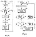
- FIG. 4is a flow chart for a process performed within the tire condition sensor unit of FIG. 2 ;
- FIG. 5is a flow chart for a process performed within the vehicle-based unit of FIG. 3 .
- a tire condition communication system 10is schematically shown within an associated vehicle 12 in FIG. 1 .
- the vehicle 12has a plurality of inflatable tires (e.g., 14 A).
- the vehicle 12has four tires 14 A– 14 D.
- the vehicle 12may have a different number of tires.
- the vehicle 12may include a fifth tire (not shown) that is stored as a spare tire.
- the system 10includes a plurality of tire condition sensor units (e.g., 18 A) for sensing one or more tire conditions at the vehicle tires (e.g., 14 A).
- the number of tire condition sensor units 18 A– 18 Dis equal to the number of tires 14 A– 14 D provided within the vehicle 12 .
- all of the tire condition sensor units 18 A– 18 Dhave the same components. Identical components are identified with identical reference numerals, with different alphabetic suffixes. It is to be appreciated that, except as noted, all of the tire condition sensor units 18 A– 18 D function in the same manner. For brevity, operation of one of the tire condition sensor units (e.g., 18 A) is discussed in detail, with the understanding that the discussion is generally applicable to the other tire condition sensor units (e.g., 18 B– 18 D).
- Each tire condition sensor unit(e.g., 18 A) includes a power supply (e.g., a battery 20 A) that provides electrical energy to various components within the respective sensor unit.
- the electrical energyenables the tire condition sensor unit (e.g., 18 A) to energize a radio frequency antenna (e.g., 22 A) to emit a radio frequency signal (e.g., 24 A) that conveys one or more sensed conditions along with a fixed identification to a central, vehicle-based unit 28 .
- a radio frequency antenna 30receives the signal (e.g., 24 A) from the tire condition sensor unit (e.g., 18 A) and the conveyed information is processed.
- the system 10is designed to operate with the signals (e.g., 24 A) in the UHF portion of the radio frequency range.
- each antenna (e.g., 22 A) in conjunction with the antenna 30comprises part of a means for communication from the respective tire condition sensor unit (e.g., 18 A) to the vehicle-based unit 28 .
- a power supply (e.g., a vehicle battery) 34which is operatively connected to the vehicle-based unit 28 , provides electrical energy to permit performance of the processing and the like.
- the vehicle-based unit 28utilizes the processed information to provide information to a vehicle operator via an indicator device 38 .
- the indicator device 38may be a visual display that is located on an instrument panel of the vehicle 12 . Accordingly, the vehicle operator is apprised of the sensed condition(s) at the tire (e.g., 14 A).
- the sensed conditionmay be any condition at the tire (e.g., 14 A).
- the sensed conditionmay be inflation pressure of the tire (e.g., 14 A), temperature of the tire, motion of the tire, or even a diagnostic condition of the tire condition sensor unit (e.g., 18 A) itself.
- the system 10includes a plurality of antennas 40 A– 40 D that are operatively connected 42 A– 42 D to the vehicle-based unit 28 .
- Each antennae.g., 40 A
- Each antennais controlled to be energized by the vehicle-based unit 28 to output an initiation signal (e.g., 44 A) that causes an associated one (e.g., 18 A) of the tire condition sensor units to respond with its radio frequency signal (e.g., 24 A).
- each initiation signal(e.g., 44 A) is a request that causes a radio frequency signal response from the associated tire condition sensor unit (e.g., 18 A).
- the information that is provided to the vehicle operatoralso includes tire location (e.g., left front). Accordingly, the vehicle operator is made aware of the tire condition (e.g., low inflation pressure) of the certain tire, without having to separately determine which tire is associated with the tire condition.
- each initiation signalis a low frequency signal that is provided in the form of a magnetic field or magnetic induction signal.
- the frequency of the initiation signals ( 44 A– 44 D)is much lower that the frequency of the radio frequency signals ( 24 A– 24 D) that convey the tire condition information to the vehicle-based unit 28 .
- the frequencies of the initiation signals 44 A– 44 Dare each at or near 125 kHz.
- the antennas 40 A– 40 Dare magnetic field induction coils.
- the antennas 40 A– 40 Dare referred to as low frequency antennas.
- other frequenciese.g., 13 MHz
- Each low frequency antenna(e.g., 40 A) is mounted on the vehicle 12 at a location adjacent to a respective one (e.g., 14 A) of the vehicle tires.
- each low frequency antenna(e.g., 40 A) is mounted within the wheel well associated with the respective tire (e.g., 14 A).
- Signal strength of each low frequency initiation signal(e.g., 44 A) drops considerably as the distance from the outputting low frequency antenna (e.g., 40 A) increases.
- magnetic field signal strengthdecreases as a function of the inverse of the cube of the distance (1/D 3 ) from the antenna.
- the low frequency initiation signalsare output at a strength to only permeate the space within the associated wheel well, about the associated tire.
- the low frequency initiation signalsare preferably not output at a strength to noticeably permeate the space about any of the other tires (e.g., 14 B– 14 D).
- Each tire condition sensor unit(e.g., 18 A) includes a low frequency reception antenna (e.g., 48 A) for receiving the low frequency initiation signal (e.g., 44 A) that is output from the low frequency antenna (e.g., 40 A) located adjacent to the respective tire (e.g., 14 A) to which the tire condition sensor unit is associated.
- the low frequency reception antennas 48 A– 48 Dare magnetic induction coils.
- each associated pair of low frequency antennas(e.g., 40 A and 48 A) comprise part of a means for communication from the vehicle-based unit 28 to the respective tire condition sensor unit (e.g., 18 A).
- the communication from the vehicle-based unit 28 to the respective tire condition sensor unit (e.g., 18 A)is a stimulus only and does not convey information, such as identification information.
- the pairing of low frequency antennas (e.g., 40 A and 48 A) as means for communication from the vehicle-based unit 28 to the respective tire condition sensor unit (e.g., 18 A)provides sufficient ability to properly select a tire location.
- the vehicle-based unit 28when the vehicle-based unit 28 “desires” to receive sensory information from the tire (e.g., 14 A) at a certain tire mount location (e.g., left front), the vehicle-based unit causes the low frequency antenna (e.g., 40 A) associated with that location to output the low frequency initiation signal (e.g., 44 A).
- the tire condition sensor unite.g., 18 A
- the radio frequency signale.g., 24 A
- the radio frequency signalconveys the sensed condition information.
- the vehicle-based unit 28“anticipates” a radio frequency response signal (e.g., 24 A) from the tire condition sensor unit (e.g., 18 A) that is associated with the certain low frequency antenna.
- the vehicle-based unit 28stimulates the low frequency antenna at a right, rear tire location, the vehicle-based unit anticipates that the tire condition sensor unit at the right, rear tire will output its radio frequency signal.
- the vehicle-based unit 28sequentially (e.g., in a series) stimulates the low frequency antennas 40 A– 40 D, and accordingly sequentially receives the radio frequency response signals 24 A– 24 D.
- an initiation signalmay be received from a different system (not shown) located on a different vehicle (not shown) that is located in close proximity to the subject vehicle 12 . Such an occurrence may cause the tire condition sensor unit that is the unintended recipient of the initiation signal to output a radio frequency response signal. Also, it is contemplated that the vehicle-based unit 28 may receive a stray radio frequency signal from the tire condition sensor unit (not shown) of the different system located on the different vehicle (not shown), even if the tire condition sensor unit of the different system did not receive an initiation signal from the subject vehicle.
- each radio frequency signalconveys a fixed identification.
- the vehicle-based unit 28has been taught or has learned to recognize the fixed identifications of the tires 14 A– 14 D associated with the vehicle 12 within which the system is provided. However, even if the tires 14 A– 14 D are rotated, the vehicle-based unit 28 is still able to correctly identify the location (e.g., left-front) of the tire (e.g., 14 A) and associated tire condition sensor unit (e.g., 18 A) because of the stimulus-response relationship that is provided by the low frequency initiation signal (e.g., 44 A) causing the radio frequency response signal (e.g., 24 A).
- the fixed identificationis utilized to verify that the tire condition sensor unit (e.g., 18 A) that provided the radio frequency response signal (e.g., 24 A) is associated with a tire (e.g., 14 A) on the vehicle 12 .
- the vehicle-based unit 28is able to recognize a signal mistakenly sent from one tire condition sensor unit (e.g., 24 C) due to noise. Such recognition occurs even if the mistakenly sent signal occurs when the vehicle-based unit is expecting a signal from another tire condition sensor unit (e.g., 24 A).
- FIG. 2schematically illustrates one example of the tire condition sensor units 18 (generically shown without alphabetic suffixes on the reference numerals).
- the low frequency reception antenna 48is operatively connected 50 to a low frequency signal detector 52 .
- a controller 54is operatively connected 56 to the low frequency signal detector 52 .
- the controller 54receives sensory information from one or more sensors 58 that are operatively connected 60 to the controller 54 .
- the controller 54also receives a fixed identification from a fixed identification memory 62 that is operatively connected 64 to the controller 54 .
- the fixed identification memory 62is a permanent, read only memory.
- the controller 54is further operatively connected 66 to radio frequency transmit circuitry 68 .
- a message packet that contains the sensory information and the fixed identificationis assembled by the controller 54 and provided to the radio frequency transmit circuitry 68 .
- the radio frequency transmit circuitry 68provides an electrical stimulus signal 70 to the antenna 22 that causes the antenna to output the radio frequency response signal that conveys the sensory information and the fixed identification.
- the low frequency antenna 48 /low frequency signal detector 52 , the sensor(s) 58 , the fixed identification memory 62 , and the radio frequency transmit circuitry 68 /radio frequency antenna 22are operatively connected together through the controller 54 .
- the operationis such that the receipt of the initiation signal (e.g., 44 A, FIG. 1 ) causes the output of the radio frequency response signal (e.g., 24 A).
- FIG. 3schematically illustrates one example of the vehicle-based unit 28 .
- a low frequency selection and driver component 74is operatively connected 42 A– 42 D to the plurality of low frequency antennas 40 A– 40 D.
- a controller 76 of the vehicle-based unit 28is also operatively connected 78 to the low frequency selection and driver component 74 .
- the controller 76provides a control signal to the low frequency selection and driver component 74 to cause a stimulation signal to be provided to one of the low frequency antennas (e.g., 40 A).
- a communication interaction with one of the tire condition sensor unitsis initiated.
- the antenna 30is operatively connected 80 to radio frequency receive circuitry 82 at the vehicle-based unit 28 .
- the radio frequency response signal that is received by the antenna 30is provided as an electrical stimulation signal to the radio frequency receive circuitry 82 .
- the radio frequency receive circuitry 82is operatively connected 84 to the controller 76 such that the contents of the received radio frequency response signal are conveyed to the controller 76 .
- the controller 76processes the received information from the radio frequency response signal. In particular, the controller 76 compares the signal-conveyed identification to an identification provided from an identifications memory 86 that is operatively connected 88 to the controller 76 . If the identification (i.e., from a tire condition sensor unit located at a tire on the vehicle) is a valid identification, the controller 76 further processes the information conveyed via the signal and provides an appropriate control signal to the indicator device 38 .
- the signalconveys tire location and condition information. For example, if the sensed condition is inflation pressure, the controller 76 provides control signals such that the indicator device 38 provides an indication of the sensed pressure and the location of the tire.
- the vehicle-based unit 28includes one or more components (e.g., 92) operatively (e.g., 94) connected to the controller 76 , and/or one or more connections (e.g., 96) from other vehicle systems to the vehicle-based unit that permit the vehicle-based unit to accomplish various additional functions.
- a learn mode component 92may be utilized to cause the vehicle-based unit 28 , and thus the system 10 , to perform function(s) such that correct and current identifications are stored in the memory 86 and used in the system 10 .
- a vehicle speed(e.g., from a transmission sensor) is provided to the controller 76 .
- the controller 78may use the speed indication to modify the rate of initiating communication with the sensor units to receive updates on the sensed tire condition.
- frequency of occurrence of updatingis proportional to the vehicle speed.
- a process 200 performed within the tire condition sensor unit 18 of FIG. 2is initiated at step 202 and proceeds to step 204 .
- the tire condition sensor unit 18is in a sleep mode, in order to conserve battery power.
- step 206determines whether the determination at step 206 is affirmative (i.e., an initiation signal is received) the process 200 proceeds from step 206 to step 208 .
- step 208the one or more conditions are sensed.
- the fixed tire identificationis retrieved from memory.
- step 212the message packet is assembled and the response signal is transmitted.
- the process 200again enters a sleep mode (i.e., the process 200 proceeds from step 212 to step 204 ).
- FIG. 5An example of a process 300 performed within the vehicle-based unit 28 is shown in FIG. 5 .
- the process 300is initiated at step 302 and proceeds to step 304 .
- a tire locationis selected.
- the low frequency antenna (e.g., 40 A) associated with that tire locationis energized to transmit its initiation signal (e.g., 44 A).
- initiation signale.g. 44 A.
- step 310an error message is provided via the indicator device 38 such that the vehicle operator is apprised of the non-receipt of a tire condition signal.
- step 310the process 300 goes to step 304 to select a tire location.
- step 308determines whether a radio frequency response signal is received. If a radio frequency response signal is received, the determination at step 308 is affirmative. Upon an affirmative determination at step 308 , the process 300 proceeds to step 312 . At step 312 , it is determined whether the fixed identification provided via the radio frequency response signal is valid (i.e., does the identification match an identification from the memory 86 at the vehicle-based unit 28 ). If the determination at step 312 is negative (i.e., the identification is invalid), the process 300 proceeds from step 312 to step 314 . At step 314 , the information data is ignored. Upon completion of step 314 , the process 300 proceeds to step 304 .
- step 312determines whether the receive radio frequency response signal (e.g., 24 A) conveys a valid fixed identification. If the receive radio frequency response signal (e.g., 24 A) conveys a valid fixed identification, the determination at step 312 is affirmative. Upon the affirmative determination at step 312 , the process 300 proceeds to step 316 wherein the information is provided to the vehicle operator via the indicator device 38 . Upon completion of step 316 , the process 300 proceeds to step 304 .
- the receive radio frequency response signale.g., 24 A
- the present inventionpermits the vehicle-based unit 28 , at the vehicle 12 to control the rate of sensor update.
- the control provided by the vehicle-based unit 28prevents signal collisions, and thus reduces the need for repeated signal transmissions. If interference of a signal does occur, communication can immediately be re-initialized. Further, the system can truly be operated in an ignition key-on mode, because radio frequency transmission is controlled from the “vehicle side.”
- the need for radio frequency wake-up messagesmay be reduced, the size of radio frequency messages may be reduced, and the efforts needed to synchronize messages may be reduced.
- Such features mentioned abovemay help to prolong battery life at the tire condition sensor units 18 A– 18 D.
- the inventionmay be easily integrated with other/existing radio frequency systems, such as remote convenience systems.
- vehicle side controlcould help ensure sensed tire condition signals are not transmitted during receipt of a remote convenience control signal.
- tire condition monitoringe.g., inflation pressure monitoring
- remote convenience functionse.g., remote keyless entry
- the vehicle-based unit 18can interface with one or more existing vehicle systems to derive information that is usable to determine need to update, frequency of updating, etc.
- the vehicle-based unit 18may interface a vehicle speed sensing system to vary update frequency based upon vehicle velocity (e.g., increased rate of update for increased vehicle speed).
- the present inventionhelps avoid the need for a person (e.g., vehicle operator or service technician) to initiate a location identification learning scenario upon the occurrence of a tire location change (e.g., a routine tire location rotation). Still further, small size of tire condition sensor units can be achieved via the removal of components that may no longer be needed, such as centrifugal switches.
- the present inventionalso provides for an easy identification learn mode.
- the initial learning of identification codes at the assembly location of the systemdoes not require preceding identification numbers into the vehicle-based unit.
- the sensor units at the installed tiresare merely sequentially polled (e.g., communicate is a cycle) to transmit to the vehicle-based unit.
- the vehicle-based unitUpon receipt of each signal, the vehicle-based unit is apprised of the identification that is currently associated with that tire location and stores that identification and location as a pair in memory.
- an assembly facilitye.g., an original equipment manufacture plant
- the present inventionalso provides for ease in learning a new/replacement identification.
- a new/replacement identificationcan be utilized when a sensor unit, or an entire tire with sensor unit, is replaced.
- the vehicle-based unitUpon replacement, the vehicle-based unit will receive a new identification each time an initiation signal is sent to that tire location. Initially, it is contemplated that the vehicle-based unit may disregard the response as it contains a previously unrecognized identification. However, the vehicle-based unit counts the number of occurrences of responses that contain the new identification and after a predetermined number of occurrences of the new identification, the vehicle-based unit accepts the new identification and stores the new identification and the location as a memory pair.
Landscapes
- Engineering & Computer Science (AREA)
- Mechanical Engineering (AREA)
- Arrangements For Transmission Of Measured Signals (AREA)
Abstract
Description
Claims (46)
Priority Applications (3)
| Application Number | Priority Date | Filing Date | Title |
|---|---|---|---|
| US09/687,709US7015801B1 (en) | 2000-10-13 | 2000-10-13 | Vehicle-controlled tire condition sensor communication utilizing fixed tire identification |
| EP01122017AEP1197356B1 (en) | 2000-10-13 | 2001-09-13 | Vehicle-controlled tire condition sensor communication utilizing fixed tire identification |
| DE60118074TDE60118074T2 (en) | 2000-10-13 | 2001-09-13 | Vehicle-controlled tire condition sensor communication with solid tire identification |
Applications Claiming Priority (1)
| Application Number | Priority Date | Filing Date | Title |
|---|---|---|---|
| US09/687,709US7015801B1 (en) | 2000-10-13 | 2000-10-13 | Vehicle-controlled tire condition sensor communication utilizing fixed tire identification |
Publications (1)
| Publication Number | Publication Date |
|---|---|
| US7015801B1true US7015801B1 (en) | 2006-03-21 |
Family
ID=24761504
Family Applications (1)
| Application Number | Title | Priority Date | Filing Date |
|---|---|---|---|
| US09/687,709Expired - LifetimeUS7015801B1 (en) | 2000-10-13 | 2000-10-13 | Vehicle-controlled tire condition sensor communication utilizing fixed tire identification |
Country Status (3)
| Country | Link |
|---|---|
| US (1) | US7015801B1 (en) |
| EP (1) | EP1197356B1 (en) |
| DE (1) | DE60118074T2 (en) |
Cited By (32)
| Publication number | Priority date | Publication date | Assignee | Title |
|---|---|---|---|---|
| US20050087593A1 (en)* | 2003-10-22 | 2005-04-28 | Benedict Robert L. | Method of integrating tire identification into a vehicle information system |
| US20050104722A1 (en)* | 2003-11-18 | 2005-05-19 | Tom Tang | Universal tire pressure monitor |
| US20080074248A1 (en)* | 2006-09-19 | 2008-03-27 | Denso Corporation | Wheel position detecting device that performs dedicated local communication for each wheel and tire air pressure detecting device including the same |
| US20080197983A1 (en)* | 2006-11-30 | 2008-08-21 | Patent Navigation Inc. | Conditional RFID |
| US20080272900A1 (en)* | 2004-04-01 | 2008-11-06 | Conti Temic Microelectronic Gmbh | Procedure and Facility for Transmission Between a Control Device and a Wheel Module |
| US20090031795A1 (en)* | 2006-01-10 | 2009-02-05 | Bridgestone Corporation | Tire checking device, tire checking system and tire checking method |
| US20090079556A1 (en)* | 2007-09-21 | 2009-03-26 | Advanced Tire Pressure Systems, Inc. | Tire pressure monitoring system having a collapsible casing |
| US20090102635A1 (en)* | 2007-10-23 | 2009-04-23 | Michelin Recherche Et Technique S.A. | Method of managing a network of sensors, a sensor network, and a vehicle provided with such a network |
| US20090121857A1 (en)* | 2007-11-11 | 2009-05-14 | Jeffrey Stegman | Comprehensive Status Indicator For Motor Vehicle Monitoring System |
| US20090273461A1 (en)* | 2008-05-05 | 2009-11-05 | Gm Global Technology Operations, Inc. | System and method for identifying a spare wheel |
| US20090289783A1 (en)* | 2008-05-20 | 2009-11-26 | Hyundai Motor Company | System for automatically recognizing locations of respective tires |
| US7705719B2 (en) | 2006-09-19 | 2010-04-27 | Denso Corporation | Wheel position detecting device and tire air pressure detecting device using the same |
| US20100109857A1 (en)* | 2008-11-05 | 2010-05-06 | Brian Bennie | Trailer Tire Pressure Monitoring System |
| US20100207752A1 (en)* | 2009-02-19 | 2010-08-19 | Hyde Stephen L | Tire pressure sensor location identification |
| US20100300192A1 (en)* | 2009-05-27 | 2010-12-02 | Honda Motor Co., Ltd. | Tire pressure monitoring system and pressure monitoring unit |
| US20110209091A1 (en)* | 2010-02-24 | 2011-08-25 | Visteon Global Technologies, Inc. | System and method to measure bandwidth in human to machine interfaces |
| US8169311B1 (en) | 1999-12-15 | 2012-05-01 | Automotive Technologies International, Inc. | Wireless transmission system for vehicular component control and monitoring |
| US8502655B2 (en) | 2011-08-09 | 2013-08-06 | Continental Automotive Systems, Inc. | Protocol misinterpretation avoidance apparatus and method for a tire pressure monitoring system |
| US8576060B2 (en) | 2011-08-09 | 2013-11-05 | Continental Automotive Systems, Inc. | Protocol arrangement in a tire pressure monitoring system |
| US8692661B2 (en) | 2007-07-03 | 2014-04-08 | Continental Automotive Systems, Inc. | Universal tire pressure monitoring sensor |
| US8742914B2 (en) | 2011-08-09 | 2014-06-03 | Continental Automotive Systems, Inc. | Tire pressure monitoring apparatus and method |
| US8751092B2 (en) | 2011-01-13 | 2014-06-10 | Continental Automotive Systems, Inc. | Protocol protection |
| US9024743B2 (en) | 2011-08-09 | 2015-05-05 | Continental Automotive System, Inc. | Apparatus and method for activating a localization process for a tire pressure monitor |
| US9446636B2 (en) | 2014-02-26 | 2016-09-20 | Continental Automotive Systems, Inc. | Pressure check tool and method of operating the same |
| US9517664B2 (en) | 2015-02-20 | 2016-12-13 | Continental Automotive Systems, Inc. | RF transmission method and apparatus in a tire pressure monitoring system |
| US9676238B2 (en) | 2011-08-09 | 2017-06-13 | Continental Automotive Systems, Inc. | Tire pressure monitor system apparatus and method |
| US9925836B2 (en)* | 2013-09-10 | 2018-03-27 | Denso Corporation | Facility-use management system, in-vehicle control apparatus, and in-facility apparatus |
| US10220660B2 (en) | 2015-08-03 | 2019-03-05 | Continental Automotive Systems, Inc. | Apparatus, system and method for configuring a tire information sensor with a transmission protocol based on vehicle trigger characteristics |
| US10460226B2 (en) | 2014-12-23 | 2019-10-29 | Bridgestone Americas Tire Operations, Llc | Tire having radio frequency identification device for monitoring structural health |
| US20190329607A1 (en)* | 2016-12-19 | 2019-10-31 | Continental Automotive Gmbh | Electronic wheel unit and control device for a wheel-monitoring system of a vehicle, wheel-monitoring system for a vehicle and method for monitoring wheels in a vehicle |
| CN114571924A (en)* | 2022-03-21 | 2022-06-03 | 奇瑞汽车股份有限公司 | Tire pressure sensor positioning method and device and vehicle |
| US11458781B1 (en)* | 2020-11-09 | 2022-10-04 | Marc Tobias | System for vehicle monitoring utilizing tire pressure sensors |
Families Citing this family (16)
| Publication number | Priority date | Publication date | Assignee | Title |
|---|---|---|---|---|
| US6667687B1 (en)* | 2000-11-14 | 2003-12-23 | Trw Inc. | Tire condition sensor communication with duty-cycled, amplified tire-side reception |
| US6612165B2 (en)* | 2002-02-04 | 2003-09-02 | Trw Inc. | Tire pressure monitoring system with pressure gauge operating mode for indicating when air pressure within a tire is within a predetermined pressure range |
| US6700480B2 (en)* | 2002-04-29 | 2004-03-02 | Robert Bosch Corporation | Addressable vehicle monitoring system and method |
| JP3636184B2 (en)* | 2002-07-31 | 2005-04-06 | 株式会社デンソー | Tire pressure sensor ID registration method and ID registration system, tire pressure monitoring system, tire pressure sensor, and smart control system |
| DE10235127A1 (en) | 2002-08-01 | 2004-02-19 | Beru Ag | Device for monitoring and wireless signaling of a pressure or a change in pressure in pneumatic tires |
| US6985076B1 (en)* | 2002-08-07 | 2006-01-10 | Ford Global Technologies, Llc | Method and system for detecting the presence of a spare replacement in a tire pressure monitoring system for an automotive vehicle |
| JP3952993B2 (en) | 2002-09-24 | 2007-08-01 | 株式会社デンソー | Tire pressure monitoring system |
| JP2004299463A (en) | 2003-03-28 | 2004-10-28 | Pacific Ind Co Ltd | Tire condition monitoring device |
| JP2004299448A (en)* | 2003-03-28 | 2004-10-28 | Pacific Ind Co Ltd | Receiver for tire condition monitoring device and tire condition monitoring device |
| GB0319548D0 (en)* | 2003-08-20 | 2003-09-24 | Trw Ltd | Tyre pressure monitoring apparatus |
| DE102004021774A1 (en)* | 2004-04-30 | 2005-11-24 | Texas Instruments Deutschland Gmbh | Tire pressure monitoring system |
| FR2872087B1 (en)* | 2004-06-28 | 2008-02-15 | Michelin Soc Tech | MOUNTING ASSEMBLY OF A WHEEL AND A TIRE, COMPRISING MEANS FOR MONITORING THE PRESSURE REGENERATING IN THE INTERIOR OF THE TIRE, SYSTEM COMPRISING SUCH AN ASSEMBLY |
| JP2006062516A (en)* | 2004-08-26 | 2006-03-09 | Pacific Ind Co Ltd | Tire condition monitoring device, transmission device, and receiving device |
| JP4548113B2 (en) | 2004-12-22 | 2010-09-22 | 株式会社デンソー | Tire pressure detector |
| US7385485B2 (en)* | 2005-03-18 | 2008-06-10 | Infineon Technologies Ag | Smart time tire monitoring system |
| FR2891222A1 (en)* | 2006-02-28 | 2007-03-30 | Siemens Vdo Automotive Sas | Tire pressure monitoring module operation mode controlling method for motor vehicle, involves programming CPU and pressure monitoring modules to implement procedures for switching operation of modules between waiting and wake states |
Citations (16)
| Publication number | Priority date | Publication date | Assignee | Title |
|---|---|---|---|---|
| US3810090A (en)* | 1972-09-15 | 1974-05-07 | Avco Corp | Pneumatic tire low pressure monitoring and warning system |
| US4761644A (en) | 1985-06-03 | 1988-08-02 | Aisin Seiki Kabushikikaisha | Data transmission system |
| US4816802A (en)* | 1985-04-18 | 1989-03-28 | Ben F. Doerksen | Tire pressure monitoring system |
| US5196845A (en) | 1988-10-24 | 1993-03-23 | Compagnie Generale Des Etablissements Michelin | Antenna for tire monitoring device |
| US5463374A (en) | 1994-03-10 | 1995-10-31 | Delco Electronics Corporation | Method and apparatus for tire pressure monitoring and for shared keyless entry control |
| US5557552A (en)* | 1993-03-24 | 1996-09-17 | Nippondenso Co., Ltd. | System for projecting vehicle speed and tire condition monitoring system using same |
| US5573610A (en)* | 1994-06-03 | 1996-11-12 | Bridgestone/Firestone, Inc. | Tires containing a monitoring device for monitoring an engineering condition therein |
| US5602524A (en) | 1992-02-26 | 1997-02-11 | Mock; Markus | Device for monitoring the air-pressure in pneumatic tires fitted on vehicle wheels |
| US5612671A (en)* | 1995-12-11 | 1997-03-18 | Delco Electronics Corp. | Method of learning tire pressure transmitter ID |
| US5880363A (en) | 1996-08-09 | 1999-03-09 | Temic Telefunken Microelectronic Gmbh | Process for checking air pressure in vehicle wheel tires |
| US5883305A (en)* | 1996-09-27 | 1999-03-16 | Motorola, Inc. | Tire pressure monitoring system |
| US5924055A (en) | 1994-11-14 | 1999-07-13 | The Yokohama Rubber Co., Ltd. | Vehicle tire air pressure monitor |
| US6011483A (en) | 1996-02-06 | 2000-01-04 | Nec Corporation | Battery built-in wireless ID card unit and ID verification unit |
| EP1026015A2 (en) | 1999-02-05 | 2000-08-09 | Schrader-Bridgeport International, Inc | Method and apparatus for a remote tire pressure monitoring system |
| US6362733B1 (en)* | 1999-08-17 | 2002-03-26 | Pacific Industrial Co., Ltd. | Tire inflation pressure monitor and monitoring method |
| US6435020B1 (en)* | 1998-08-10 | 2002-08-20 | Continental Aktiengesellschaft | Method for allocating tire pressure control devices to wheel positions in a tire pressure control system of a motor vehicle |
- 2000
- 2000-10-13USUS09/687,709patent/US7015801B1/ennot_activeExpired - Lifetime
- 2001
- 2001-09-13EPEP01122017Apatent/EP1197356B1/ennot_activeExpired - Lifetime
- 2001-09-13DEDE60118074Tpatent/DE60118074T2/ennot_activeExpired - Lifetime
Patent Citations (17)
| Publication number | Priority date | Publication date | Assignee | Title |
|---|---|---|---|---|
| US3810090A (en)* | 1972-09-15 | 1974-05-07 | Avco Corp | Pneumatic tire low pressure monitoring and warning system |
| US4816802A (en)* | 1985-04-18 | 1989-03-28 | Ben F. Doerksen | Tire pressure monitoring system |
| US4761644A (en) | 1985-06-03 | 1988-08-02 | Aisin Seiki Kabushikikaisha | Data transmission system |
| US5196845A (en) | 1988-10-24 | 1993-03-23 | Compagnie Generale Des Etablissements Michelin | Antenna for tire monitoring device |
| US5602524A (en) | 1992-02-26 | 1997-02-11 | Mock; Markus | Device for monitoring the air-pressure in pneumatic tires fitted on vehicle wheels |
| US5557552A (en)* | 1993-03-24 | 1996-09-17 | Nippondenso Co., Ltd. | System for projecting vehicle speed and tire condition monitoring system using same |
| US5463374A (en) | 1994-03-10 | 1995-10-31 | Delco Electronics Corporation | Method and apparatus for tire pressure monitoring and for shared keyless entry control |
| US5573610A (en)* | 1994-06-03 | 1996-11-12 | Bridgestone/Firestone, Inc. | Tires containing a monitoring device for monitoring an engineering condition therein |
| US5924055A (en) | 1994-11-14 | 1999-07-13 | The Yokohama Rubber Co., Ltd. | Vehicle tire air pressure monitor |
| US5612671A (en)* | 1995-12-11 | 1997-03-18 | Delco Electronics Corp. | Method of learning tire pressure transmitter ID |
| US6011483A (en) | 1996-02-06 | 2000-01-04 | Nec Corporation | Battery built-in wireless ID card unit and ID verification unit |
| US5880363A (en) | 1996-08-09 | 1999-03-09 | Temic Telefunken Microelectronic Gmbh | Process for checking air pressure in vehicle wheel tires |
| US5883305A (en)* | 1996-09-27 | 1999-03-16 | Motorola, Inc. | Tire pressure monitoring system |
| US6435020B1 (en)* | 1998-08-10 | 2002-08-20 | Continental Aktiengesellschaft | Method for allocating tire pressure control devices to wheel positions in a tire pressure control system of a motor vehicle |
| EP1026015A2 (en) | 1999-02-05 | 2000-08-09 | Schrader-Bridgeport International, Inc | Method and apparatus for a remote tire pressure monitoring system |
| US6710708B2 (en)* | 1999-02-05 | 2004-03-23 | Schrader-Bridgeport International, Inc. | Method and apparatus for a remote tire pressure monitoring system |
| US6362733B1 (en)* | 1999-08-17 | 2002-03-26 | Pacific Industrial Co., Ltd. | Tire inflation pressure monitor and monitoring method |
Non-Patent Citations (5)
| Title |
|---|
| An Internet press release from Siemens Automotive dated Jan. 24, 2001. |
| U.S. Appl. No. 09/711,588, filed Nov. 14, 2000, DeZorzi "Tire Condition Sensor Communication With Duty-Cycle Amplified Tire-Side Reception". |
| U.S. Appl. No. 09/727,251, filed Nov. 29, 2000, Juzswik "Vehicle Communicaiton For Tire Sensor Initiation And Vehicle Keyless Entry Via A Shared Resource". |
| U.S. Appl. No. 09/752,951, filed Jan. 2, 2001 Dixit et al. entitled Tire Condition Sensor Communication with Tire Location Provided Via Manually Inputted Update. |
| U.S. Appl. No. 09/753,290, filed Jan. 2, 2001 Dixit et al. entitled "Tire Condition Sensor Communication With Tire Location Provided Via Vehicle-Mounted Identification Units". |
Cited By (50)
| Publication number | Priority date | Publication date | Assignee | Title |
|---|---|---|---|---|
| US8169311B1 (en) | 1999-12-15 | 2012-05-01 | Automotive Technologies International, Inc. | Wireless transmission system for vehicular component control and monitoring |
| US7104438B2 (en)* | 2003-10-22 | 2006-09-12 | The Goodyear Tire & Rubber Company | Method of integrating tire identification into a vehicle information system |
| US20050087593A1 (en)* | 2003-10-22 | 2005-04-28 | Benedict Robert L. | Method of integrating tire identification into a vehicle information system |
| US20050104722A1 (en)* | 2003-11-18 | 2005-05-19 | Tom Tang | Universal tire pressure monitor |
| US7518495B2 (en) | 2003-11-18 | 2009-04-14 | Lear Corporation | Universal tire pressure monitor |
| US20080272900A1 (en)* | 2004-04-01 | 2008-11-06 | Conti Temic Microelectronic Gmbh | Procedure and Facility for Transmission Between a Control Device and a Wheel Module |
| US7876206B2 (en)* | 2004-04-01 | 2011-01-25 | Conti Temic Microelectronic Gmbh | Procedure and facility for transmission between a control device and a wheel module |
| US8220324B2 (en)* | 2006-01-10 | 2012-07-17 | Bridgestone Corporation | Tire checking device, tire checking system and tire checking method |
| US20090031795A1 (en)* | 2006-01-10 | 2009-02-05 | Bridgestone Corporation | Tire checking device, tire checking system and tire checking method |
| US7705714B2 (en) | 2006-09-19 | 2010-04-27 | Denso Corporation | Wheel position detecting device that performs dedicated local communication for each wheel and tire air pressure detecting device including the same |
| US20080074248A1 (en)* | 2006-09-19 | 2008-03-27 | Denso Corporation | Wheel position detecting device that performs dedicated local communication for each wheel and tire air pressure detecting device including the same |
| US7705719B2 (en) | 2006-09-19 | 2010-04-27 | Denso Corporation | Wheel position detecting device and tire air pressure detecting device using the same |
| US8994533B2 (en)* | 2006-11-30 | 2015-03-31 | Patent Navigation, Inc. | Conditional RFID |
| US9639723B1 (en) | 2006-11-30 | 2017-05-02 | Patent Navigation | Conditional RFID |
| US20080197983A1 (en)* | 2006-11-30 | 2008-08-21 | Patent Navigation Inc. | Conditional RFID |
| US8742913B2 (en) | 2007-07-03 | 2014-06-03 | Continental Automotive Systems, Inc. | Method of preparing a universal tire pressure monitoring sensor |
| US8692661B2 (en) | 2007-07-03 | 2014-04-08 | Continental Automotive Systems, Inc. | Universal tire pressure monitoring sensor |
| US7804396B2 (en) | 2007-09-21 | 2010-09-28 | Advanced Tire Pressure Systems, Inc. | Tire pressure monitoring system having a collapsible casing |
| US20090079556A1 (en)* | 2007-09-21 | 2009-03-26 | Advanced Tire Pressure Systems, Inc. | Tire pressure monitoring system having a collapsible casing |
| US20090102635A1 (en)* | 2007-10-23 | 2009-04-23 | Michelin Recherche Et Technique S.A. | Method of managing a network of sensors, a sensor network, and a vehicle provided with such a network |
| US20090121857A1 (en)* | 2007-11-11 | 2009-05-14 | Jeffrey Stegman | Comprehensive Status Indicator For Motor Vehicle Monitoring System |
| US8183992B2 (en)* | 2007-11-11 | 2012-05-22 | Doran Manufacturing Llc | Comprehensive status indicator for motor vehicle monitoring system |
| US20090273461A1 (en)* | 2008-05-05 | 2009-11-05 | Gm Global Technology Operations, Inc. | System and method for identifying a spare wheel |
| US8072319B2 (en)* | 2008-05-05 | 2011-12-06 | GM Global Technology Operations LLC | System and method for identifying a spare wheel |
| US7994904B2 (en)* | 2008-05-20 | 2011-08-09 | Hyundai Motor Company | System for automatically recognizing locations of respective tires |
| US20090289783A1 (en)* | 2008-05-20 | 2009-11-26 | Hyundai Motor Company | System for automatically recognizing locations of respective tires |
| US7920058B2 (en) | 2008-11-05 | 2011-04-05 | Ford Global Technologies | Trailer tire pressure monitoring system |
| US20100109857A1 (en)* | 2008-11-05 | 2010-05-06 | Brian Bennie | Trailer Tire Pressure Monitoring System |
| US8217776B2 (en) | 2009-02-19 | 2012-07-10 | Chrysler Group Llc | Tire pressure sensor location identification |
| US20100207752A1 (en)* | 2009-02-19 | 2010-08-19 | Hyde Stephen L | Tire pressure sensor location identification |
| US8279055B2 (en)* | 2009-05-27 | 2012-10-02 | Honda Motor Co., Ltd. | Tire pressure monitoring system and pressure monitoring unit |
| US20100300192A1 (en)* | 2009-05-27 | 2010-12-02 | Honda Motor Co., Ltd. | Tire pressure monitoring system and pressure monitoring unit |
| US20110209091A1 (en)* | 2010-02-24 | 2011-08-25 | Visteon Global Technologies, Inc. | System and method to measure bandwidth in human to machine interfaces |
| US8751092B2 (en) | 2011-01-13 | 2014-06-10 | Continental Automotive Systems, Inc. | Protocol protection |
| US8502655B2 (en) | 2011-08-09 | 2013-08-06 | Continental Automotive Systems, Inc. | Protocol misinterpretation avoidance apparatus and method for a tire pressure monitoring system |
| US9776463B2 (en) | 2011-08-09 | 2017-10-03 | Continental Automotive Systems, Inc. | Apparatus and method for data transmissions in a tire pressure monitor |
| US9024743B2 (en) | 2011-08-09 | 2015-05-05 | Continental Automotive System, Inc. | Apparatus and method for activating a localization process for a tire pressure monitor |
| US9259980B2 (en) | 2011-08-09 | 2016-02-16 | Continental Automotive Systems, Inc. | Apparatus and method for data transmissions in a tire pressure monitor |
| US8742914B2 (en) | 2011-08-09 | 2014-06-03 | Continental Automotive Systems, Inc. | Tire pressure monitoring apparatus and method |
| US8576060B2 (en) | 2011-08-09 | 2013-11-05 | Continental Automotive Systems, Inc. | Protocol arrangement in a tire pressure monitoring system |
| US9676238B2 (en) | 2011-08-09 | 2017-06-13 | Continental Automotive Systems, Inc. | Tire pressure monitor system apparatus and method |
| US9925836B2 (en)* | 2013-09-10 | 2018-03-27 | Denso Corporation | Facility-use management system, in-vehicle control apparatus, and in-facility apparatus |
| US9446636B2 (en) | 2014-02-26 | 2016-09-20 | Continental Automotive Systems, Inc. | Pressure check tool and method of operating the same |
| US10460226B2 (en) | 2014-12-23 | 2019-10-29 | Bridgestone Americas Tire Operations, Llc | Tire having radio frequency identification device for monitoring structural health |
| US9517664B2 (en) | 2015-02-20 | 2016-12-13 | Continental Automotive Systems, Inc. | RF transmission method and apparatus in a tire pressure monitoring system |
| US10220660B2 (en) | 2015-08-03 | 2019-03-05 | Continental Automotive Systems, Inc. | Apparatus, system and method for configuring a tire information sensor with a transmission protocol based on vehicle trigger characteristics |
| US20190329607A1 (en)* | 2016-12-19 | 2019-10-31 | Continental Automotive Gmbh | Electronic wheel unit and control device for a wheel-monitoring system of a vehicle, wheel-monitoring system for a vehicle and method for monitoring wheels in a vehicle |
| US10836221B2 (en)* | 2016-12-19 | 2020-11-17 | Continental Automotive Gmbh | Electronic wheel unit and control device for a wheel-monitoring system of a vehicle, wheel-monitoring system for a vehicle and method for monitoring wheels in a vehicle |
| US11458781B1 (en)* | 2020-11-09 | 2022-10-04 | Marc Tobias | System for vehicle monitoring utilizing tire pressure sensors |
| CN114571924A (en)* | 2022-03-21 | 2022-06-03 | 奇瑞汽车股份有限公司 | Tire pressure sensor positioning method and device and vehicle |
Also Published As
| Publication number | Publication date |
|---|---|
| DE60118074D1 (en) | 2006-05-11 |
| EP1197356A2 (en) | 2002-04-17 |
| EP1197356B1 (en) | 2006-03-22 |
| EP1197356A3 (en) | 2003-11-12 |
| DE60118074T2 (en) | 2006-12-14 |
Similar Documents
| Publication | Publication Date | Title |
|---|---|---|
| US7015801B1 (en) | Vehicle-controlled tire condition sensor communication utilizing fixed tire identification | |
| US20030145650A1 (en) | Tire pressure monitoring system with pressure gauge operating mode for indicating when air pressure within a tire is within a predetermined pressure range | |
| EP1205317B2 (en) | Tire condition sensor communication with duty-cycled, amplified tire-side reception | |
| US20020084896A1 (en) | Tire condition sensor communication with tire location provided via vehicle-mounted identification units | |
| EP1419908B1 (en) | Method and apparatus for associating tires with tire locations of a vehicle | |
| US6838985B2 (en) | System and method for remote tire pressure monitoring with low frequency initiation | |
| US7019628B2 (en) | Tire monitoring and keyless entry system | |
| US8144023B2 (en) | Tire inflation pressure detecting apparatus capable of triggering only selected transceiver to perform task | |
| US7750798B2 (en) | Wheel position detecting device that verifies accuracy of detection using trigger signal reception strength and tire air pressure detecting device including the same | |
| US7705714B2 (en) | Wheel position detecting device that performs dedicated local communication for each wheel and tire air pressure detecting device including the same | |
| US6922142B2 (en) | Tire air pressure monitoring system | |
| EP1829713A2 (en) | Tire inflation pressure detecting apparatus with function of identifiying running and spare wheels | |
| US20030107481A1 (en) | Tire condition monitoring apparatus and method | |
| US20080068147A1 (en) | Wheel position detecting device and tire air pressure detecting device using the same | |
| US7791460B2 (en) | Tire pressure monitoring system with reliable wireless communication between wheel-based transceivers and vehicle body-based transceiver | |
| GB2385931A (en) | Tyre pressure monitoring system | |
| US7854163B2 (en) | Wheel identifying apparatus and tire inflation pressure detecting apparatus with function of wheel identification | |
| KR20070005518A (en) | Tire pressure detection system with wheel identification and wheel identification | |
| US7154414B2 (en) | System and method for remote tire pressure monitoring | |
| GB2385927A (en) | Automatic tire location recognition using temperature and rotation direction data | |
| EP1270276B1 (en) | Tire condition monitoring apparatus | |
| US8026803B2 (en) | Apparatus and process for monitoring a vehicle condition | |
| JP4123979B2 (en) | Tire pressure monitoring system | |
| EP1384605B1 (en) | Tire condition monitoring apparatus | |
| KR100769043B1 (en) | TPS automatic tire recognition device and method |
Legal Events
| Date | Code | Title | Description |
|---|---|---|---|
| AS | Assignment | Owner name:TRW INC., OHIO Free format text:ASSIGNMENT OF ASSIGNORS INTEREST;ASSIGNOR:JUZSWIK, DAVID LEONARD;REEL/FRAME:011253/0428 Effective date:20001012 | |
| AS | Assignment | Owner name:JPMORGAN CHASE BANK, NEW YORK Free format text:THE US GUARANTEE AND COLLATERAL AGREEMENT;ASSIGNOR:TRW AUTOMOTIVE U.S. LLC;REEL/FRAME:014022/0720 Effective date:20030228 | |
| STCF | Information on status: patent grant | Free format text:PATENTED CASE | |
| FPAY | Fee payment | Year of fee payment:4 | |
| AS | Assignment | Owner name:JPMORGAN CHASE BANK, N.A., AS COLLATERAL AGENT, NE Free format text:SECURITY AGREEMENT;ASSIGNORS:TRW VEHICLE SAFETY SYSTEMS INC.;TRW AUTOMOTIVE U.S. LLC;KELSEY-HAYES COMPANY;REEL/FRAME:029529/0534 Effective date:20120928 | |
| FPAY | Fee payment | Year of fee payment:8 | |
| AS | Assignment | Owner name:TRW INTELLECTUAL PROPERTY CORP., MICHIGAN Free format text:RELEASE OF SECURITY INTEREST;ASSIGNOR:JPMORGAN CHASE BANK, N.A.;REEL/FRAME:031645/0697 Effective date:20131028 Owner name:TRW AUTOMOTIVE U.S. LLC, MICHIGAN Free format text:RELEASE OF SECURITY INTEREST;ASSIGNOR:JPMORGAN CHASE BANK, N.A.;REEL/FRAME:031645/0697 Effective date:20131028 Owner name:KELSEY-HAYES COMPANY, MICHIGAN Free format text:RELEASE OF SECURITY INTEREST;ASSIGNOR:JPMORGAN CHASE BANK, N.A.;REEL/FRAME:031645/0697 Effective date:20131028 Owner name:TRW VEHICLE SAFETY SYSTEMS INC., MICHIGAN Free format text:RELEASE OF SECURITY INTEREST;ASSIGNOR:JPMORGAN CHASE BANK, N.A.;REEL/FRAME:031645/0697 Effective date:20131028 | |
| MAFP | Maintenance fee payment | Free format text:PAYMENT OF MAINTENANCE FEE, 12TH YEAR, LARGE ENTITY (ORIGINAL EVENT CODE: M1553) Year of fee payment:12 |