US7014636B2 - Osmotic delivery device having a two-way valve and a dynamically self-adjusting flow channel - Google Patents
Osmotic delivery device having a two-way valve and a dynamically self-adjusting flow channelDownload PDFInfo
- Publication number
- US7014636B2 US7014636B2US10/302,104US30210402AUS7014636B2US 7014636 B2US7014636 B2US 7014636B2US 30210402 AUS30210402 AUS 30210402AUS 7014636 B2US7014636 B2US 7014636B2
- Authority
- US
- United States
- Prior art keywords
- closing member
- fluid chamber
- pressure
- delivery system
- agent delivery
- Prior art date
- Legal status (The legal status is an assumption and is not a legal conclusion. Google has not performed a legal analysis and makes no representation as to the accuracy of the status listed.)
- Expired - Lifetime, expires
Links
- 230000003204osmotic effectEffects0.000titledescription16
- 239000012530fluidSubstances0.000claimsabstractdescription103
- 230000009286beneficial effectEffects0.000claimsabstractdescription99
- 239000003795chemical substances by applicationSubstances0.000claimsdescription132
- 239000002775capsuleSubstances0.000claimsdescription51
- 239000002357osmotic agentSubstances0.000claimsdescription21
- 238000007906compressionMethods0.000claimsdescription9
- 230000006835compressionEffects0.000claimsdescription9
- 238000004891communicationMethods0.000claimsdescription8
- XUIMIQQOPSSXEZ-UHFFFAOYSA-NSiliconChemical compound[Si]XUIMIQQOPSSXEZ-UHFFFAOYSA-N0.000claimsdescription2
- 229910052710siliconInorganic materials0.000claimsdescription2
- 239000010703siliconSubstances0.000claimsdescription2
- 230000000903blocking effectEffects0.000claims1
- 238000009792diffusion processMethods0.000abstractdescription18
- 239000000203mixtureSubstances0.000abstractdescription18
- 238000009472formulationMethods0.000abstractdescription14
- 230000008595infiltrationEffects0.000abstractdescription2
- 238000001764infiltrationMethods0.000abstractdescription2
- XLYOFNOQVPJJNP-UHFFFAOYSA-NwaterSubstancesOXLYOFNOQVPJJNP-UHFFFAOYSA-N0.000description15
- 239000012528membraneSubstances0.000description14
- 239000000463materialSubstances0.000description13
- 230000001276controlling effectEffects0.000description8
- 238000000034methodMethods0.000description7
- 238000013461designMethods0.000description6
- -1polytetrafluoroethylenePolymers0.000description6
- 108090000623proteins and genesProteins0.000description6
- 238000013459approachMethods0.000description5
- 210000003722extracellular fluidAnatomy0.000description5
- 229920003023plasticPolymers0.000description5
- 239000004033plasticSubstances0.000description5
- 229920000642polymerPolymers0.000description5
- 102000004169proteins and genesHuman genes0.000description5
- 102000018997Growth HormoneHuman genes0.000description4
- 108010051696Growth HormoneProteins0.000description4
- FAPWRFPIFSIZLT-UHFFFAOYSA-MSodium chlorideChemical compound[Na+].[Cl-]FAPWRFPIFSIZLT-UHFFFAOYSA-M0.000description4
- RTAQQCXQSZGOHL-UHFFFAOYSA-NTitaniumChemical compound[Ti]RTAQQCXQSZGOHL-UHFFFAOYSA-N0.000description4
- 238000002513implantationMethods0.000description4
- 229910052751metalInorganic materials0.000description4
- 239000002184metalSubstances0.000description4
- 230000001105regulatory effectEffects0.000description4
- 229910001220stainless steelInorganic materials0.000description4
- 239000010935stainless steelSubstances0.000description4
- 229920001169thermoplasticPolymers0.000description4
- 229920002725thermoplastic elastomerPolymers0.000description4
- 239000004416thermosoftening plasticSubstances0.000description4
- 239000010936titaniumSubstances0.000description4
- 229910052719titaniumInorganic materials0.000description4
- 229920000106Liquid crystal polymerPolymers0.000description3
- 239000004977Liquid-crystal polymers (LCPs)Substances0.000description3
- 229920006169PerfluoroelastomerPolymers0.000description3
- 239000013543active substanceSubstances0.000description3
- 229910045601alloyInorganic materials0.000description3
- 239000000956alloySubstances0.000description3
- 230000008901benefitEffects0.000description3
- 238000012377drug deliveryMethods0.000description3
- 229920001971elastomerPolymers0.000description3
- XLXSAKCOAKORKW-UHFFFAOYSA-NgonadorelinChemical compoundC1CCC(C(=O)NCC(N)=O)N1C(=O)C(CCCN=C(N)N)NC(=O)C(CC(C)C)NC(=O)CNC(=O)C(NC(=O)C(CO)NC(=O)C(CC=1C2=CC=CC=C2NC=1)NC(=O)C(CC=1NC=NC=1)NC(=O)C1NC(=O)CC1)CC1=CC=C(O)C=C1XLXSAKCOAKORKW-UHFFFAOYSA-N0.000description3
- 230000037361pathwayEffects0.000description3
- 102000004196processed proteins & peptidesHuman genes0.000description3
- 108090000765processed proteins & peptidesProteins0.000description3
- 238000005086pumpingMethods0.000description3
- 229920002818(Hydroxyethyl)methacrylatePolymers0.000description2
- IAKHMKGGTNLKSZ-INIZCTEOSA-N(S)-colchicineChemical compoundC1([C@@H](NC(C)=O)CC2)=CC(=O)C(OC)=CC=C1C1=C2C=C(OC)C(OC)=C1OCIAKHMKGGTNLKSZ-INIZCTEOSA-N0.000description2
- 102000004190EnzymesHuman genes0.000description2
- 108090000790EnzymesProteins0.000description2
- 229910000640Fe alloyInorganic materials0.000description2
- 101000904173Homo sapiens Progonadoliberin-1Proteins0.000description2
- WOBHKFSMXKNTIM-UHFFFAOYSA-NHydroxyethyl methacrylateChemical compoundCC(=C)C(=O)OCCOWOBHKFSMXKNTIM-UHFFFAOYSA-N0.000description2
- 102100037852Insulin-like growth factor IHuman genes0.000description2
- 206010028980NeoplasmDiseases0.000description2
- 239000004952PolyamideSubstances0.000description2
- 239000004743PolypropyleneSubstances0.000description2
- 102100024028Progonadoliberin-1Human genes0.000description2
- 229910000831SteelInorganic materials0.000description2
- 101000996723Sus scrofa Gonadotropin-releasing hormone receptorProteins0.000description2
- 229920000122acrylonitrile butadiene styrenePolymers0.000description2
- 210000001124body fluidAnatomy0.000description2
- 239000010839body fluidSubstances0.000description2
- 239000013013elastic materialSubstances0.000description2
- 230000008030eliminationEffects0.000description2
- 238000003379elimination reactionMethods0.000description2
- 238000005516engineering processMethods0.000description2
- 229940088598enzymeDrugs0.000description2
- 229920001973fluoroelastomerPolymers0.000description2
- 229940088597hormoneDrugs0.000description2
- 239000005556hormoneSubstances0.000description2
- 239000007943implantSubstances0.000description2
- NOESYZHRGYRDHS-UHFFFAOYSA-NinsulinChemical compoundN1C(=O)C(NC(=O)C(CCC(N)=O)NC(=O)C(CCC(O)=O)NC(=O)C(C(C)C)NC(=O)C(NC(=O)CN)C(C)CC)CSSCC(C(NC(CO)C(=O)NC(CC(C)C)C(=O)NC(CC=2C=CC(O)=CC=2)C(=O)NC(CCC(N)=O)C(=O)NC(CC(C)C)C(=O)NC(CCC(O)=O)C(=O)NC(CC(N)=O)C(=O)NC(CC=2C=CC(O)=CC=2)C(=O)NC(CSSCC(NC(=O)C(C(C)C)NC(=O)C(CC(C)C)NC(=O)C(CC=2C=CC(O)=CC=2)NC(=O)C(CC(C)C)NC(=O)C(C)NC(=O)C(CCC(O)=O)NC(=O)C(C(C)C)NC(=O)C(CC(C)C)NC(=O)C(CC=2NC=NC=2)NC(=O)C(CO)NC(=O)CNC2=O)C(=O)NCC(=O)NC(CCC(O)=O)C(=O)NC(CCCNC(N)=N)C(=O)NCC(=O)NC(CC=3C=CC=CC=3)C(=O)NC(CC=3C=CC=CC=3)C(=O)NC(CC=3C=CC(O)=CC=3)C(=O)NC(C(C)O)C(=O)N3C(CCC3)C(=O)NC(CCCCN)C(=O)NC(C)C(O)=O)C(=O)NC(CC(N)=O)C(O)=O)=O)NC(=O)C(C(C)CC)NC(=O)C(CO)NC(=O)C(C(C)O)NC(=O)C1CSSCC2NC(=O)C(CC(C)C)NC(=O)C(NC(=O)C(CCC(N)=O)NC(=O)C(CC(N)=O)NC(=O)C(NC(=O)C(N)CC=1C=CC=CC=1)C(C)C)CC1=CN=CN1NOESYZHRGYRDHS-UHFFFAOYSA-N0.000description2
- 238000003754machiningMethods0.000description2
- 238000004519manufacturing processMethods0.000description2
- 230000013011matingEffects0.000description2
- 238000005259measurementMethods0.000description2
- 238000000465mouldingMethods0.000description2
- BASFCYQUMIYNBI-UHFFFAOYSA-NplatinumChemical compound[Pt]BASFCYQUMIYNBI-UHFFFAOYSA-N0.000description2
- 229920001643poly(ether ketone)Polymers0.000description2
- 229920002647polyamidePolymers0.000description2
- 229920001184polypeptidePolymers0.000description2
- 229920001155polypropylenePolymers0.000description2
- 229920002635polyurethanePolymers0.000description2
- 239000004814polyurethaneSubstances0.000description2
- 229920003031santoprenePolymers0.000description2
- 239000011780sodium chlorideSubstances0.000description2
- 239000010959steelSubstances0.000description2
- BJFIDCADFRDPIO-DZCXQCEKSA-N(2S)-N-[(2S)-6-amino-1-[(2-amino-2-oxoethyl)amino]-1-oxohexan-2-yl]-1-[[(4R,7S,10S,13S,16S,19R)-19-amino-7-(2-amino-2-oxoethyl)-10-(3-amino-3-oxopropyl)-16-[(4-hydroxyphenyl)methyl]-6,9,12,15,18-pentaoxo-13-(phenylmethyl)-1,2-dithia-5,8,11,14,17-pentazacycloeicos-4-yl]-oxomethyl]-2-pyrrolidinecarboxamideChemical compoundNCCCC[C@@H](C(=O)NCC(N)=O)NC(=O)[C@@H]1CCCN1C(=O)[C@H]1NC(=O)[C@H](CC(N)=O)NC(=O)[C@H](CCC(N)=O)NC(=O)[C@H](CC=2C=CC=CC=2)NC(=O)[C@H](CC=2C=CC(O)=CC=2)NC(=O)[C@@H](N)CSSC1BJFIDCADFRDPIO-DZCXQCEKSA-N0.000description1
- JSPNNZKWADNWHI-PNANGNLXSA-N(2r)-2-hydroxy-n-[(2s,3r,4e,8e)-3-hydroxy-9-methyl-1-[(2r,3r,4s,5s,6r)-3,4,5-trihydroxy-6-(hydroxymethyl)oxan-2-yl]oxyoctadeca-4,8-dien-2-yl]heptadecanamideChemical compoundCCCCCCCCCCCCCCC[C@@H](O)C(=O)N[C@H]([C@H](O)\C=C\CC\C=C(/C)CCCCCCCCC)CO[C@@H]1O[C@H](CO)[C@@H](O)[C@H](O)[C@H]1OJSPNNZKWADNWHI-PNANGNLXSA-N0.000description1
- DEQANNDTNATYII-OULOTJBUSA-N(4r,7s,10s,13r,16s,19r)-10-(4-aminobutyl)-19-[[(2r)-2-amino-3-phenylpropanoyl]amino]-16-benzyl-n-[(2r,3r)-1,3-dihydroxybutan-2-yl]-7-[(1r)-1-hydroxyethyl]-13-(1h-indol-3-ylmethyl)-6,9,12,15,18-pentaoxo-1,2-dithia-5,8,11,14,17-pentazacycloicosane-4-carboxaChemical compoundC([C@@H](N)C(=O)N[C@H]1CSSC[C@H](NC(=O)[C@H]([C@@H](C)O)NC(=O)[C@H](CCCCN)NC(=O)[C@@H](CC=2C3=CC=CC=C3NC=2)NC(=O)[C@H](CC=2C=CC=CC=2)NC1=O)C(=O)N[C@H](CO)[C@H](O)C)C1=CC=CC=C1DEQANNDTNATYII-OULOTJBUSA-N0.000description1
- 239000000275Adrenocorticotropic HormoneSubstances0.000description1
- 208000023275Autoimmune diseaseDiseases0.000description1
- 102100026189Beta-galactosidaseHuman genes0.000description1
- 108010039209Blood Coagulation FactorsProteins0.000description1
- 102000015081Blood Coagulation FactorsHuman genes0.000description1
- 208000019838Blood diseaseDiseases0.000description1
- 102000055006CalcitoninHuman genes0.000description1
- 108060001064CalcitoninProteins0.000description1
- 101800001982CholecystokininProteins0.000description1
- 102000011022Chorionic GonadotropinHuman genes0.000description1
- 108010062540Chorionic GonadotropinProteins0.000description1
- 102100022641Coagulation factor IXHuman genes0.000description1
- 206010010099Combined immunodeficiencyDiseases0.000description1
- RYGMFSIKBFXOCR-UHFFFAOYSA-NCopperChemical compound[Cu]RYGMFSIKBFXOCR-UHFFFAOYSA-N0.000description1
- 101800000414CorticotropinProteins0.000description1
- 108010091893CosyntropinProteins0.000description1
- 208000011231Crohn diseaseDiseases0.000description1
- 201000003883Cystic fibrosisDiseases0.000description1
- 102000004127CytokinesHuman genes0.000description1
- 108090000695CytokinesProteins0.000description1
- 229920002943EPDM rubberPolymers0.000description1
- 108010092674EnkephalinsProteins0.000description1
- 102400001368Epidermal growth factorHuman genes0.000description1
- 101800003838Epidermal growth factorProteins0.000description1
- 102000003951ErythropoietinHuman genes0.000description1
- 108090000394ErythropoietinProteins0.000description1
- 108010076282Factor IXProteins0.000description1
- 108010054218Factor VIIIProteins0.000description1
- 102000001690Factor VIIIHuman genes0.000description1
- 102000012673Follicle Stimulating HormoneHuman genes0.000description1
- 108010079345Follicle Stimulating HormoneProteins0.000description1
- 108010086677GonadotropinsProteins0.000description1
- 102000006771GonadotropinsHuman genes0.000description1
- 108010069236GoserelinProteins0.000description1
- BLCLNMBMMGCOAS-URPVMXJPSA-NGoserelinChemical compoundC([C@@H](C(=O)N[C@H](COC(C)(C)C)C(=O)N[C@@H](CC(C)C)C(=O)N[C@@H](CCCN=C(N)N)C(=O)N1[C@@H](CCC1)C(=O)NNC(N)=O)NC(=O)[C@H](CO)NC(=O)[C@H](CC=1C2=CC=CC=C2NC=1)NC(=O)[C@H](CC=1NC=NC=1)NC(=O)[C@H]1NC(=O)CC1)C1=CC=C(O)C=C1BLCLNMBMMGCOAS-URPVMXJPSA-N0.000description1
- 102100039619Granulocyte colony-stimulating factorHuman genes0.000description1
- 102100039620Granulocyte-macrophage colony-stimulating factorHuman genes0.000description1
- 208000003807Graves DiseaseDiseases0.000description1
- 208000015023Graves' diseaseDiseases0.000description1
- 239000000095Growth Hormone-Releasing HormoneSubstances0.000description1
- 208000031886HIV InfectionsDiseases0.000description1
- 208000037357HIV infectious diseaseDiseases0.000description1
- 208000031220HemophiliaDiseases0.000description1
- 208000009292Hemophilia ADiseases0.000description1
- 101000746367Homo sapiens Granulocyte colony-stimulating factorProteins0.000description1
- 101000746373Homo sapiens Granulocyte-macrophage colony-stimulating factorProteins0.000description1
- 101000599951Homo sapiens Insulin-like growth factor IProteins0.000description1
- 101001076407Homo sapiens Interleukin-1 receptor antagonist proteinProteins0.000description1
- 101000716102Homo sapiens T-cell surface glycoprotein CD4Proteins0.000description1
- 206010020772HypertensionDiseases0.000description1
- 102000008394Immunoglobulin FragmentsHuman genes0.000description1
- 108010021625Immunoglobulin FragmentsProteins0.000description1
- 208000026350Inborn Genetic diseaseDiseases0.000description1
- 208000022559Inflammatory bowel diseaseDiseases0.000description1
- 102000004877InsulinHuman genes0.000description1
- 108090001061InsulinProteins0.000description1
- 108090000723Insulin-Like Growth Factor IProteins0.000description1
- 108010050904InterferonsProteins0.000description1
- 102000014150InterferonsHuman genes0.000description1
- 229940119178Interleukin 1 receptor antagonistDrugs0.000description1
- 102000051628Interleukin-1 receptor antagonistHuman genes0.000description1
- 102000000588Interleukin-2Human genes0.000description1
- 108010002350Interleukin-2Proteins0.000description1
- XNSAINXGIQZQOO-UHFFFAOYSA-NL-pyroglutamyl-L-histidyl-L-proline amideNatural productsNC(=O)C1CCCN1C(=O)C(NC(=O)C1NC(=O)CC1)CC1=CN=CN1XNSAINXGIQZQOO-UHFFFAOYSA-N0.000description1
- 108010059881LactaseProteins0.000description1
- 201000010538Lactose IntoleranceDiseases0.000description1
- URLZCHNOLZSCCA-VABKMULXSA-NLeu-enkephalinChemical compoundC([C@@H](C(=O)N[C@@H](CC(C)C)C(O)=O)NC(=O)CNC(=O)CNC(=O)[C@@H](N)CC=1C=CC(O)=CC=1)C1=CC=CC=C1URLZCHNOLZSCCA-VABKMULXSA-N0.000description1
- 108010000817LeuprolideProteins0.000description1
- 102000009151Luteinizing HormoneHuman genes0.000description1
- 108010073521Luteinizing HormoneProteins0.000description1
- 108010048179LypressinProteins0.000description1
- 241000124008MammaliaSpecies0.000description1
- 208000024556Mendelian diseaseDiseases0.000description1
- 108010021717NafarelinProteins0.000description1
- 108010016076OctreotideProteins0.000description1
- 102000006877Pituitary HormonesHuman genes0.000description1
- 108010047386Pituitary HormonesProteins0.000description1
- 229920012485Plasticized Polyvinyl chloridePolymers0.000description1
- 239000004698PolyethyleneSubstances0.000description1
- 239000004642PolyimideSubstances0.000description1
- 239000004793PolystyreneSubstances0.000description1
- 102000003946ProlactinHuman genes0.000description1
- 108010057464ProlactinProteins0.000description1
- 208000001647Renal InsufficiencyDiseases0.000description1
- 108010086019SecretinProteins0.000description1
- 102100037505SecretinHuman genes0.000description1
- 206010040070Septic ShockDiseases0.000description1
- 101710142969SomatoliberinProteins0.000description1
- 102100022831SomatoliberinHuman genes0.000description1
- 102000005157SomatostatinHuman genes0.000description1
- 108010056088SomatostatinProteins0.000description1
- 102100036011T-cell surface glycoprotein CD4Human genes0.000description1
- 102000011923ThyrotropinHuman genes0.000description1
- 108010061174ThyrotropinProteins0.000description1
- 239000000627Thyrotropin-Releasing HormoneSubstances0.000description1
- 102400000336Thyrotropin-releasing hormoneHuman genes0.000description1
- 101800004623Thyrotropin-releasing hormoneProteins0.000description1
- 229910001069Ti alloyInorganic materials0.000description1
- 102000003978Tissue Plasminogen ActivatorHuman genes0.000description1
- 108090000373Tissue Plasminogen ActivatorProteins0.000description1
- NRTOMJZYCJJWKI-UHFFFAOYSA-NTitanium nitrideChemical compound[Ti]#NNRTOMJZYCJJWKI-UHFFFAOYSA-N0.000description1
- 108060008682Tumor Necrosis FactorProteins0.000description1
- 108060008683Tumor Necrosis Factor ReceptorProteins0.000description1
- GXBMIBRIOWHPDT-UHFFFAOYSA-NVasopressinNatural productsN1C(=O)C(CC=2C=C(O)C=CC=2)NC(=O)C(N)CSSCC(C(=O)N2C(CCC2)C(=O)NC(CCCN=C(N)N)C(=O)NCC(N)=O)NC(=O)C(CC(N)=O)NC(=O)C(CCC(N)=O)NC(=O)C1CC1=CC=CC=C1GXBMIBRIOWHPDT-UHFFFAOYSA-N0.000description1
- 108010004977VasopressinsProteins0.000description1
- 102000002852VasopressinsHuman genes0.000description1
- 238000010521absorption reactionMethods0.000description1
- MLSVJHOYXJGGTR-IFHOVBQLSA-Nacetic acid;(2s)-n-[(2r)-1-[(2-amino-2-oxoethyl)amino]-5-(diaminomethylideneamino)-1-oxopentan-2-yl]-1-[(4r,7s,10s,13s,16s)-7-(2-amino-2-oxoethyl)-10-(3-amino-3-oxopropyl)-13-benzyl-16-[(4-hydroxyphenyl)methyl]-6,9,12,15,18-pentaoxo-1,2-dithia-5,8,11,14,1Chemical compoundCC(O)=O.C([C@H]1C(=O)N[C@H](C(N[C@@H](CC(N)=O)C(=O)N[C@@H](CSSCCC(=O)N[C@@H](CC=2C=CC(O)=CC=2)C(=O)N1)C(=O)N1[C@@H](CCC1)C(=O)N[C@H](CCCNC(N)=N)C(=O)NCC(N)=O)=O)CCC(=O)N)C1=CC=CC=C1MLSVJHOYXJGGTR-IFHOVBQLSA-N0.000description1
- DPXJVFZANSGRMM-UHFFFAOYSA-Nacetic acid;2,3,4,5,6-pentahydroxyhexanal;sodiumChemical compound[Na].CC(O)=O.OCC(O)C(O)C(O)C(O)C=ODPXJVFZANSGRMM-UHFFFAOYSA-N0.000description1
- 229920006243acrylic copolymerPolymers0.000description1
- 239000004676acrylonitrile butadiene styreneSubstances0.000description1
- 230000009471actionEffects0.000description1
- 201000009628adenosine deaminase deficiencyDiseases0.000description1
- 239000000853adhesiveSubstances0.000description1
- 230000001070adhesive effectEffects0.000description1
- 230000001919adrenal effectEffects0.000description1
- 239000000556agonistSubstances0.000description1
- 150000001408amidesChemical class0.000description1
- 229940024606amino acidDrugs0.000description1
- 150000001413amino acidsChemical class0.000description1
- 239000005557antagonistSubstances0.000description1
- 239000007864aqueous solutionSubstances0.000description1
- 239000007900aqueous suspensionSubstances0.000description1
- KBZOIRJILGZLEJ-LGYYRGKSSA-NargipressinChemical compoundC([C@H]1C(=O)N[C@@H](CCC(N)=O)C(=O)N[C@@H](CC(N)=O)C(=O)N[C@@H](CSSC[C@@H](C(N[C@@H](CC=2C=CC(O)=CC=2)C(=O)N1)=O)N)C(=O)N1[C@@H](CCC1)C(=O)N[C@@H](CCCN=C(N)N)C(=O)NCC(N)=O)C1=CC=CC=C1KBZOIRJILGZLEJ-LGYYRGKSSA-N0.000description1
- 208000036556autosomal recessive T cell-negative B cell-negative NK cell-negative due to adenosine deaminase deficiency severe combined immunodeficiencyDiseases0.000description1
- 229910052790berylliumInorganic materials0.000description1
- ATBAMAFKBVZNFJ-UHFFFAOYSA-Nberyllium atomChemical compound[Be]ATBAMAFKBVZNFJ-UHFFFAOYSA-N0.000description1
- 108010005774beta-GalactosidaseProteins0.000description1
- 239000011230binding agentSubstances0.000description1
- 230000005540biological transmissionEffects0.000description1
- 239000003114blood coagulation factorSubstances0.000description1
- 229920005549butyl rubberPolymers0.000description1
- 229960004015calcitoninDrugs0.000description1
- BBBFJLBPOGFECG-VJVYQDLKSA-NcalcitoninChemical compoundN([C@H](C(=O)N[C@@H](CC(C)C)C(=O)NCC(=O)N[C@@H](CCCCN)C(=O)N[C@@H](CC(C)C)C(=O)N[C@@H](CO)C(=O)N[C@@H](CCC(N)=O)C(=O)N[C@@H](CCC(O)=O)C(=O)N[C@@H](CC(C)C)C(=O)N[C@@H](CC=1NC=NC=1)C(=O)N[C@@H](CCCCN)C(=O)N[C@@H](CC(C)C)C(=O)N[C@@H](CCC(N)=O)C(=O)N[C@@H]([C@@H](C)O)C(=O)N[C@@H](CC=1C=CC(O)=CC=1)C(=O)N1[C@@H](CCC1)C(=O)N[C@@H](CCCNC(N)=N)C(=O)N[C@@H]([C@@H](C)O)C(=O)N[C@@H](CC(N)=O)C(=O)N[C@@H]([C@@H](C)O)C(=O)NCC(=O)N[C@@H](CO)C(=O)NCC(=O)N[C@@H]([C@@H](C)O)C(=O)N1[C@@H](CCC1)C(N)=O)C(C)C)C(=O)[C@@H]1CSSC[C@H](N)C(=O)N[C@@H](CO)C(=O)N[C@@H](CC(N)=O)C(=O)N[C@@H](CC(C)C)C(=O)N[C@@H](CO)C(=O)N[C@@H]([C@@H](C)O)C(=O)N1BBBFJLBPOGFECG-VJVYQDLKSA-N0.000description1
- 239000001768carboxy methyl celluloseSubstances0.000description1
- 239000000969carrierSubstances0.000description1
- 229930183167cerebrosideNatural products0.000description1
- RIZIAUKTHDLMQX-UHFFFAOYSA-Ncerebroside DNatural productsCCCCCCCCCCCCCCCCC(O)C(=O)NC(C(O)C=CCCC=C(C)CCCCCCCCC)COC1OC(CO)C(O)C(O)C1ORIZIAUKTHDLMQX-UHFFFAOYSA-N0.000description1
- 229940015047chorionic gonadotropinDrugs0.000description1
- 239000000788chromium alloySubstances0.000description1
- 229960001338colchicineDrugs0.000description1
- 229920000891common polymerPolymers0.000description1
- 238000013270controlled releaseMethods0.000description1
- 229920001577copolymerPolymers0.000description1
- 229910052802copperInorganic materials0.000description1
- 239000010949copperSubstances0.000description1
- 230000001054cortical effectEffects0.000description1
- IDLFZVILOHSSID-OVLDLUHVSA-NcorticotropinChemical compoundC([C@@H](C(=O)N[C@@H](CO)C(=O)N[C@@H](CCSC)C(=O)N[C@@H](CCC(O)=O)C(=O)N[C@@H](CC=1NC=NC=1)C(=O)N[C@@H](CC=1C=CC=CC=1)C(=O)N[C@@H](CCCNC(N)=N)C(=O)N[C@@H](CC=1C2=CC=CC=C2NC=1)C(=O)NCC(=O)N[C@@H](CCCCN)C(=O)N1[C@@H](CCC1)C(=O)N[C@@H](C(C)C)C(=O)NCC(=O)N[C@@H](CCCCN)C(=O)N[C@@H](CCCCN)C(=O)N[C@@H](CCCNC(N)=N)C(=O)N[C@@H](CCCNC(N)=N)C(=O)N1[C@@H](CCC1)C(=O)N[C@@H](C(C)C)C(=O)N[C@@H](CCCCN)C(=O)N[C@@H](C(C)C)C(=O)N[C@@H](CC=1C=CC(O)=CC=1)C(=O)N1[C@@H](CCC1)C(=O)N[C@@H](CC(N)=O)C(=O)NCC(=O)N[C@@H](C)C(=O)N[C@@H](CCC(O)=O)C(=O)N[C@@H](CC(O)=O)C(=O)N[C@@H](CCC(O)=O)C(=O)N[C@@H](CO)C(=O)N[C@@H](C)C(=O)N[C@@H](CCC(O)=O)C(=O)N[C@@H](C)C(=O)N[C@@H](CC=1C=CC=CC=1)C(=O)N1[C@@H](CCC1)C(=O)N[C@@H](CC(C)C)C(=O)N[C@@H](CCC(O)=O)C(=O)N[C@@H](CC=1C=CC=CC=1)C(O)=O)NC(=O)[C@@H](N)CO)C1=CC=C(O)C=C1IDLFZVILOHSSID-OVLDLUHVSA-N0.000description1
- 229960000258corticotropinDrugs0.000description1
- ZOEFCCMDUURGSE-SQKVDDBVSA-NcosyntropinChemical compoundC([C@@H](C(=O)N[C@@H](CO)C(=O)N[C@@H](CCSC)C(=O)N[C@@H](CCC(O)=O)C(=O)N[C@@H](CC=1NC=NC=1)C(=O)N[C@@H](CC=1C=CC=CC=1)C(=O)N[C@@H](CCCNC(N)=N)C(=O)N[C@@H](CC=1C2=CC=CC=C2NC=1)C(=O)NCC(=O)N[C@@H](CCCCN)C(=O)N1[C@@H](CCC1)C(=O)N[C@@H](C(C)C)C(=O)NCC(=O)N[C@@H](CCCCN)C(=O)N[C@@H](CCCCN)C(=O)N[C@@H](CCCNC(N)=N)C(=O)N[C@@H](CCCNC(N)=N)C(=O)N1[C@@H](CCC1)C(=O)N[C@@H](C(C)C)C(=O)N[C@@H](CCCCN)C(=O)N[C@@H](C(C)C)C(=O)N[C@@H](CC=1C=CC(O)=CC=1)C(=O)N1[C@@H](CCC1)C(O)=O)NC(=O)[C@@H](N)CO)C1=CC=C(O)C=C1ZOEFCCMDUURGSE-SQKVDDBVSA-N0.000description1
- 230000001351cycling effectEffects0.000description1
- 231100000433cytotoxicToxicity0.000description1
- 230000001472cytotoxic effectEffects0.000description1
- 230000007812deficiencyEffects0.000description1
- 230000001419dependent effectEffects0.000description1
- 206010012601diabetes mellitusDiseases0.000description1
- 239000012895dilutionSubstances0.000description1
- 238000010790dilutionMethods0.000description1
- 238000007599dischargingMethods0.000description1
- 208000037265diseases, disorders, signs and symptomsDiseases0.000description1
- 208000035475disorderDiseases0.000description1
- 238000006073displacement reactionMethods0.000description1
- 230000009189divingEffects0.000description1
- 229940079593drugDrugs0.000description1
- 239000003814drugSubstances0.000description1
- 239000003937drug carrierSubstances0.000description1
- 230000000694effectsEffects0.000description1
- 239000000806elastomerSubstances0.000description1
- 229940116977epidermal growth factorDrugs0.000description1
- 229940105423erythropoietinDrugs0.000description1
- 150000002148estersChemical class0.000description1
- 150000002170ethersChemical class0.000description1
- 229960004222factor ixDrugs0.000description1
- 229960000301factor viiiDrugs0.000description1
- 230000009969flowable effectEffects0.000description1
- 239000012628flowing agentSubstances0.000description1
- 229940028334follicle stimulating hormoneDrugs0.000description1
- 230000002496gastric effectEffects0.000description1
- 238000001415gene therapyMethods0.000description1
- PCHJSUWPFVWCPO-UHFFFAOYSA-NgoldChemical compound[Au]PCHJSUWPFVWCPO-UHFFFAOYSA-N0.000description1
- 229910052737goldInorganic materials0.000description1
- 239000010931goldSubstances0.000description1
- 230000001456gonadotrophEffects0.000description1
- 239000002622gonadotropinSubstances0.000description1
- 229940094892gonadotropinsDrugs0.000description1
- 229960002913goserelinDrugs0.000description1
- 208000037824growth disorderDiseases0.000description1
- 239000003102growth factorSubstances0.000description1
- 239000000122growth hormoneSubstances0.000description1
- 208000014951hematologic diseaseDiseases0.000description1
- 208000018706hematopoietic system diseaseDiseases0.000description1
- 208000006454hepatitisDiseases0.000description1
- 231100000283hepatitisToxicity0.000description1
- HCDGVLDPFQMKDK-UHFFFAOYSA-NhexafluoropropyleneChemical groupFC(F)=C(F)C(F)(F)FHCDGVLDPFQMKDK-UHFFFAOYSA-N0.000description1
- 208000033519human immunodeficiency virus infectious diseaseDiseases0.000description1
- 150000004677hydratesChemical class0.000description1
- 239000000960hypophysis hormoneSubstances0.000description1
- 229940060367inert ingredientsDrugs0.000description1
- 238000002347injectionMethods0.000description1
- 239000007924injectionSubstances0.000description1
- 229940125396insulinDrugs0.000description1
- 229940079322interferonDrugs0.000description1
- 239000003407interleukin 1 receptor blocking agentSubstances0.000description1
- 201000006370kidney failureDiseases0.000description1
- 229940116108lactaseDrugs0.000description1
- 230000002045lasting effectEffects0.000description1
- 208000032839leukemiaDiseases0.000description1
- GFIJNRVAKGFPGQ-LIJARHBVSA-NleuprolideChemical compoundCCNC(=O)[C@@H]1CCCN1C(=O)[C@H](CCCNC(N)=N)NC(=O)[C@H](CC(C)C)NC(=O)[C@@H](CC(C)C)NC(=O)[C@@H](NC(=O)[C@H](CO)NC(=O)[C@H](CC=1C2=CC=CC=C2NC=1)NC(=O)[C@H](CC=1N=CNC=1)NC(=O)[C@H]1NC(=O)CC1)CC1=CC=C(O)C=C1GFIJNRVAKGFPGQ-LIJARHBVSA-N0.000description1
- 229960004338leuprorelinDrugs0.000description1
- 239000000314lubricantSubstances0.000description1
- 229940040129luteinizing hormoneDrugs0.000description1
- 229960003837lypressinDrugs0.000description1
- 238000007734materials engineeringMethods0.000description1
- 230000007246mechanismEffects0.000description1
- 229910001092metal group alloyInorganic materials0.000description1
- 239000007769metal materialSubstances0.000description1
- 238000012986modificationMethods0.000description1
- 230000004048modificationEffects0.000description1
- 201000006417multiple sclerosisDiseases0.000description1
- RWHUEXWOYVBUCI-ITQXDASVSA-NnafarelinChemical compoundC([C@@H](C(=O)N[C@H](CC=1C=C2C=CC=CC2=CC=1)C(=O)N[C@@H](CC(C)C)C(=O)N[C@@H](CCCN=C(N)N)C(=O)N1[C@@H](CCC1)C(=O)NCC(N)=O)NC(=O)[C@H](CO)NC(=O)[C@H](CC=1C2=CC=CC=C2NC=1)NC(=O)[C@H](CC=1NC=NC=1)NC(=O)[C@H]1NC(=O)CC1)C1=CC=C(O)C=C1RWHUEXWOYVBUCI-ITQXDASVSA-N0.000description1
- 229960002333nafarelinDrugs0.000description1
- 229960002700octreotideDrugs0.000description1
- XNOPRXBHLZRZKH-DSZYJQQASA-NoxytocinChemical compoundC([C@H]1C(=O)N[C@H](C(N[C@@H](CCC(N)=O)C(=O)N[C@@H](CC(N)=O)C(=O)N[C@@H](CSSC[C@H](N)C(=O)N1)C(=O)N1[C@@H](CCC1)C(=O)N[C@@H](CC(C)C)C(=O)NCC(N)=O)=O)[C@@H](C)CC)C1=CC=C(O)C=C1XNOPRXBHLZRZKH-DSZYJQQASA-N0.000description1
- 239000000813peptide hormoneSubstances0.000description1
- 229910052697platinumInorganic materials0.000description1
- 229920002493poly(chlorotrifluoroethylene)Polymers0.000description1
- 229920003229poly(methyl methacrylate)Polymers0.000description1
- 229920001495poly(sodium acrylate) polymerPolymers0.000description1
- 229920002492poly(sulfone)Polymers0.000description1
- 229920002239polyacrylonitrilePolymers0.000description1
- 239000004417polycarbonateSubstances0.000description1
- 229920000515polycarbonatePolymers0.000description1
- 239000005023polychlorotrifluoroethylene (PCTFE) polymerSubstances0.000description1
- 229920000573polyethylenePolymers0.000description1
- 229920001721polyimidePolymers0.000description1
- 239000004926polymethyl methacrylateSubstances0.000description1
- 229920002223polystyrenePolymers0.000description1
- 229920001343polytetrafluoroethylenePolymers0.000description1
- 239000004810polytetrafluoroethyleneSubstances0.000description1
- OXCMYAYHXIHQOA-UHFFFAOYSA-Npotassium;[2-butyl-5-chloro-3-[[4-[2-(1,2,4-triaza-3-azanidacyclopenta-1,4-dien-5-yl)phenyl]phenyl]methyl]imidazol-4-yl]methanolChemical compound[K+].CCCCC1=NC(Cl)=C(CO)N1CC1=CC=C(C=2C(=CC=CC=2)C2=N[N-]N=N2)C=C1OXCMYAYHXIHQOA-UHFFFAOYSA-N0.000description1
- 230000003389potentiating effectEffects0.000description1
- 229940002612prodrugDrugs0.000description1
- 239000000651prodrugSubstances0.000description1
- 229940097325prolactinDrugs0.000description1
- XNSAINXGIQZQOO-SRVKXCTJSA-NprotirelinChemical compoundNC(=O)[C@@H]1CCCN1C(=O)[C@@H](NC(=O)[C@H]1NC(=O)CC1)CC1=CN=CN1XNSAINXGIQZQOO-SRVKXCTJSA-N0.000description1
- 229920013730reactive polymerPolymers0.000description1
- 230000009467reductionEffects0.000description1
- 238000005057refrigerationMethods0.000description1
- 239000003488releasing hormoneSubstances0.000description1
- 206010039073rheumatoid arthritisDiseases0.000description1
- 239000005060rubberSubstances0.000description1
- 150000003839saltsChemical class0.000description1
- 229960002101secretinDrugs0.000description1
- OWMZNFCDEHGFEP-NFBCVYDUSA-Nsecretin humanChemical compoundC([C@@H](C(=O)N[C@H](C(=O)N[C@@H](CO)C(=O)N[C@@H](CCC(O)=O)C(=O)N[C@@H](CC(C)C)C(=O)N[C@@H](CO)C(=O)N[C@@H](CCCNC(N)=N)C(=O)N[C@@H](CC(C)C)C(=O)N[C@@H](CCCNC(N)=N)C(=O)N[C@@H](CCC(O)=O)C(=O)NCC(=O)N[C@@H](C)C(=O)N[C@@H](CCCNC(N)=N)C(=O)N[C@@H](CC(C)C)C(=O)N[C@@H](CCC(N)=O)C(=O)N[C@@H](CCCNC(N)=N)C(=O)N[C@@H](CC(C)C)C(=O)N[C@@H](CC(C)C)C(=O)N[C@@H](CCC(N)=O)C(=O)NCC(=O)N[C@@H](CC(C)C)C(=O)N[C@@H](C(C)C)C(N)=O)[C@@H](C)O)NC(=O)[C@@H](NC(=O)CNC(=O)[C@H](CC(O)=O)NC(=O)[C@H](CO)NC(=O)[C@@H](N)CC=1NC=NC=1)[C@@H](C)O)C1=CC=CC=C1OWMZNFCDEHGFEP-NFBCVYDUSA-N0.000description1
- 230000036303septic shockEffects0.000description1
- 230000035939shockEffects0.000description1
- 229920002379silicone rubberPolymers0.000description1
- 239000004945silicone rubberSubstances0.000description1
- IZTQOLKUZKXIRV-YRVFCXMDSA-NsincalideChemical compoundC([C@@H](C(=O)N[C@@H](CCSC)C(=O)NCC(=O)N[C@@H](CC=1C2=CC=CC=C2NC=1)C(=O)N[C@@H](CCSC)C(=O)N[C@@H](CC(O)=O)C(=O)N[C@@H](CC=1C=CC=CC=1)C(N)=O)NC(=O)[C@@H](N)CC(O)=O)C1=CC=C(OS(O)(=O)=O)C=C1IZTQOLKUZKXIRV-YRVFCXMDSA-N0.000description1
- 150000003384small moleculesChemical class0.000description1
- 235000019812sodium carboxymethyl celluloseNutrition0.000description1
- 229920001027sodium carboxymethylcellulosePolymers0.000description1
- NNMHYFLPFNGQFZ-UHFFFAOYSA-Msodium polyacrylateChemical compound[Na+].[O-]C(=O)C=CNNMHYFLPFNGQFZ-UHFFFAOYSA-M0.000description1
- 229960000553somatostatinDrugs0.000description1
- NHXLMOGPVYXJNR-ATOGVRKGSA-NsomatostatinChemical compoundC([C@H]1C(=O)N[C@H](C(N[C@@H](CO)C(=O)N[C@@H](CSSC[C@@H](C(=O)N[C@@H](CCCCN)C(=O)N[C@@H](CC(N)=O)C(=O)N[C@@H](CC=2C=CC=CC=2)C(=O)N[C@@H](CC=2C=CC=CC=2)C(=O)N[C@@H](CC=2C3=CC=CC=C3NC=2)C(=O)N[C@@H](CCCCN)C(=O)N[C@H](C(=O)N1)[C@@H](C)O)NC(=O)CNC(=O)[C@H](C)N)C(O)=O)=O)[C@H](O)C)C1=CC=CC=C1NHXLMOGPVYXJNR-ATOGVRKGSA-N0.000description1
- 230000004936stimulating effectEffects0.000description1
- 230000000638stimulationEffects0.000description1
- 238000003860storageMethods0.000description1
- 201000000596systemic lupus erythematosusDiseases0.000description1
- 239000003826tabletSubstances0.000description1
- 229910052715tantalumInorganic materials0.000description1
- GUVRBAGPIYLISA-UHFFFAOYSA-Ntantalum atomChemical compound[Ta]GUVRBAGPIYLISA-UHFFFAOYSA-N0.000description1
- 229960001423tetracosactideDrugs0.000description1
- 229920006344thermoplastic copolyesterPolymers0.000description1
- 210000001685thyroid glandAnatomy0.000description1
- 229940034199thyrotropin-releasing hormoneDrugs0.000description1
- 210000001519tissueAnatomy0.000description1
- 229960000187tissue plasminogen activatorDrugs0.000description1
- 230000001052transient effectEffects0.000description1
- 239000002753trypsin inhibitorSubstances0.000description1
- 102000003390tumor necrosis factorHuman genes0.000description1
- 102000003298tumor necrosis factor receptorHuman genes0.000description1
- VBEQCZHXXJYVRD-GACYYNSASA-NuroantheloneChemical compoundC([C@@H](C(=O)N[C@H](C(=O)N[C@@H](CS)C(=O)N[C@@H](CC(N)=O)C(=O)N[C@@H](CS)C(=O)N[C@H](C(=O)N[C@@H]([C@@H](C)CC)C(=O)NCC(=O)N[C@@H](CC=1C=CC(O)=CC=1)C(=O)N[C@@H](CO)C(=O)NCC(=O)N[C@@H](CC(O)=O)C(=O)N[C@@H](CCCNC(N)=N)C(=O)N[C@@H](CS)C(=O)N[C@@H](CCC(N)=O)C(=O)N[C@@H]([C@@H](C)O)C(=O)N[C@@H](CCCNC(N)=N)C(=O)N[C@@H](CC(O)=O)C(=O)N[C@@H](CC(C)C)C(=O)N[C@@H](CCCNC(N)=N)C(=O)N[C@@H](CC=1C2=CC=CC=C2NC=1)C(=O)N[C@@H](CC=1C2=CC=CC=C2NC=1)C(=O)N[C@@H](CCC(O)=O)C(=O)N[C@@H](CC(C)C)C(=O)N[C@@H](CCCNC(N)=N)C(O)=O)C(C)C)[C@@H](C)O)NC(=O)[C@H](CO)NC(=O)[C@H](CC(O)=O)NC(=O)[C@H](CC(C)C)NC(=O)[C@H](CO)NC(=O)[C@H](CCC(O)=O)NC(=O)[C@@H](NC(=O)[C@H](CC=1NC=NC=1)NC(=O)[C@H](CCSC)NC(=O)[C@H](CS)NC(=O)[C@@H](NC(=O)CNC(=O)CNC(=O)[C@H](CC(N)=O)NC(=O)[C@H](CC(C)C)NC(=O)[C@H](CS)NC(=O)[C@H](CC=1C=CC(O)=CC=1)NC(=O)CNC(=O)[C@H](CC(O)=O)NC(=O)[C@H](CC=1C=CC(O)=CC=1)NC(=O)[C@H](CO)NC(=O)[C@H](CO)NC(=O)[C@H]1N(CCC1)C(=O)[C@H](CS)NC(=O)CNC(=O)[C@H]1N(CCC1)C(=O)[C@H](CC=1C=CC(O)=CC=1)NC(=O)[C@H](CO)NC(=O)[C@@H](N)CC(N)=O)C(C)C)[C@@H](C)CC)C1=CC=C(O)C=C1VBEQCZHXXJYVRD-GACYYNSASA-N0.000description1
- 229960003726vasopressinDrugs0.000description1
- 239000003981vehicleSubstances0.000description1
- 238000003466weldingMethods0.000description1
- 238000009736wettingMethods0.000description1
Images


Classifications
- A—HUMAN NECESSITIES
- A61—MEDICAL OR VETERINARY SCIENCE; HYGIENE
- A61K—PREPARATIONS FOR MEDICAL, DENTAL OR TOILETRY PURPOSES
- A61K9/00—Medicinal preparations characterised by special physical form
- A61K9/0012—Galenical forms characterised by the site of application
- A61K9/0019—Injectable compositions; Intramuscular, intravenous, arterial, subcutaneous administration; Compositions to be administered through the skin in an invasive manner
- A61K9/0024—Solid, semi-solid or solidifying implants, which are implanted or injected in body tissue
- A—HUMAN NECESSITIES
- A61—MEDICAL OR VETERINARY SCIENCE; HYGIENE
- A61K—PREPARATIONS FOR MEDICAL, DENTAL OR TOILETRY PURPOSES
- A61K9/00—Medicinal preparations characterised by special physical form
- A61K9/0002—Galenical forms characterised by the drug release technique; Application systems commanded by energy
- A61K9/0004—Osmotic delivery systems; Sustained release driven by osmosis, thermal energy or gas
Definitions
- the present inventionpertains to osmotically controlled implantable delivery devices, and more particularly to a delivery device having a two-way miniature valve and a dynamically self-adjusting flow channel for the regulation of back-diffusion and fluid delivery rate in an osmotically driven delivery system.
- Controlled delivery of beneficial agents, such as drugs, in the medical and the veterinary fieldshas been accomplished by a variety of methods, including implantable delivery devices, such as implantable osmotic delivery devices.
- implantable delivery devicessuch as implantable osmotic delivery devices.
- Osmotic delivery systemsare very reliable in delivering a beneficial agent over an extended period of time, called an administration period.
- osmotic delivery systemsoperate by imbibing fluid from an outside environment and releasing controlled amounts of beneficial agent from the delivery system.
- a water-attracting agent contained within the capsulecreates an osmotic pressure within the capsule, which then causes a beneficial agent within the capsule to be expelled.
- the water-attracting agentmay be the beneficial agent being delivered to the patient.
- a separate agentis used specifically for its ability to draw water into the capsule.
- the osmotic agentmay be separated from the beneficial agent within the capsule by a movable dividing member such as a piston.
- the structure of the capsuleis generally rigid such that as the osmotic agent takes in water and expands, the capsule itself does not expand.
- the agentcauses the movable dividing member to move, discharging the beneficial agent through an orifice or exit passage of the capsule.
- the beneficial agentis discharged through the exit passage at the same volumetric rate that water combines with the osmotic agent through the semi-permeable walls of the capsule.
- the orifice or exit passage of the capsuleis permanently open and thus allows for unimpeded discharge of the beneficial agent. This results in a direct fluid communication between the beneficial agent and water in the surrounding tissue of the patient. Thus, back-diffusion of the water into the beneficial agent reservoir may result.
- the orifice or exit passage of the capsuleis covered with a stretchable or elastic member or band, to reduce back-diffusion of water into the beneficial agent reservoir.
- the stretchable or elastic bandallows discharge of the beneficial agent once a threshold pressure has been overcome.
- the stretchable or elastic member or bandcloses the orifice when the pressure in the device is less than the threshold pressure.
- the orifice or exit passageis at least partially made of a stretchable or elastic material that acts to reduce back-diffusion of water into the beneficial agent reservoir.
- This stretchable or elastic materialdeforms once a threshold pressure has been achieved in the device to allow discharge of the beneficial agent.
- the stretchable orifice materialcloses when the internal pressure in the device is less than the threshold pressure.
- osmotic delivery systemsrely on the flow of interstitial body fluid across a rate-limiting membrane (also known as a semi-permeable membrane) to drive the osmotic agent expansion that in turn drives the delivery or discharge of the beneficial agent.
- a rate-limiting membranealso known as a semi-permeable membrane
- this interstitial fluidmay also diffuse into the beneficial agent via a beneficial agent delivery channel (also known as an orifice or exit passage).
- a beneficial agent delivery channelalso known as an orifice or exit passage
- implantable delivery devicesdo not compensate for variations in temperature and internal pressure that can cause the implantable delivery device to deliver beneficial agent temporarily at high or low rates.
- an implantable, osmotically driven delivery systemwill have been stored at ambient room temperature (approximately 20 to 22° C.) prior to implantation into a patient. Within a few hours following implantation, the system will subsequently come to thermal equilibrium with the patient (approximately 37° C.).
- This increase in temperaturemay cause the beneficial agent formulation within the implantable device to expand, which may result in a pressurization of the system and a rapid, short-duration delivery of beneficial agent often referred to as a start-up “burst.”
- This burstis typically followed by a short period of somewhat low agent delivery (typically lasting from less than one day to 5 days) during which time the osmotic pressure is increased to a degree equal to that of the piston friction.
- the rate of beneficial agent deliverywill rise until it obtains a steady state. Since it is the purpose of an osmotic delivery system to deliver a defined concentration of beneficial agent at a fixed rate, both the start-up “burst” and the subsequent “lag” in delivery are undesirable.
- a further aspect of an implantable, osmotically driven beneficial agent delivery systemis that it is subject to external pressure or temperature changes (e.g., scuba diving, a hot bath, or temperature cycling during shipping) which may, in turn, result in transient spikes in the beneficial agent delivery profile.
- external pressure or temperature changese.g., scuba diving, a hot bath, or temperature cycling during shipping
- Another objective of the present inventionis to provide for the elimination of back-diffusion in a relatively inexpensive manner and without requiring a relatively large or long orifice, diffusion path, or exit channel.
- An additional objective of the present inventionis to provide an implantable osmotic delivery device capable of containing the total osmotic pressure that can develop within the device without requiring relatively expensive and sophisticated fluid flow bypass pathways.
- an implantable drug delivery systemfor use in mammals (preferably in humans) includes a capsule having an impermeable outer layer.
- the capsulehas a beneficial agent delivery end and a fluid uptake end that are spaced apart from each other, but not necessarily located on opposite ends of the capsule.
- the capsulecomprises a reservoir containing a beneficial agent; a movable dividing member separating the reservoir from the osmotic engine; and an osmotic engine.
- the delivery systemincludes a means for controlling beneficial agent flow through the beneficial agent delivery end that substantially prevents flow of beneficial agent out of the capsule when pressure within the capsule is above an upper predetermined pressure and prevents flow of fluid into the capsule through the beneficial agent delivery end when the pressure within the capsule is below a lower predetermined pressure.
- beneficial agentis substantially allowed to flow out of the capsule through the beneficial agent delivery end when the pressure within the capsule is between the lower and upper predetermined pressures.
- a device for dynamically regulating the flow of a beneficial agent from a pressurized beneficial agent delivery systemincludes a hollow body having a lower port and an upper port.
- the devicealso includes a means for controlling flow of interstitial fluid through the hollow body when pressure by the beneficial agent acting upon the means for controlling flow is below a lower predetermined pressure.
- the devicealso includes a means for controlling beneficial agent flow out of the device when the pressure in the device is above an upper predetermined pressure.
- the beneficial agentis substantially allowed to flow out of the device when the pressure in the device is between the lower and upper predetermined pressures.
- a method of variably controlling the delivery of a beneficial agent from an implantable drug delivery systemincludes the steps of providing a capsule having a beneficial agent delivery end and a fluid uptake end, an agent reservoir containing a beneficial agent, an uptake reservoir containing a fluid attracting agent, and a movable dividing member between the agent reservoir and the uptake reservoir.
- the beneficial agent reservoir and the uptake reservoirare positioned adjacent the beneficial agent delivery end and the fluid uptake end, respectively.
- the methodalso includes the step of substantially preventing the flow of fluid into the capsule when a pressure within the capsule is below a lower predetermined pressure and flow of beneficial agent out of the capsule when a pressure within the capsule is above an upper predetermined pressure.
- the methodstill further includes the step of variably controlling the flow of the beneficial agent out of the capsule when the pressure is between the lower and upper predetermined pressures.
- a method of variably controlling the delivery of a beneficial agent from an implantable osmotically driven delivery systemincludes the steps of displacing a movable closing member of a valve assembly with respect to a lower port via application of fluid pressure thereon from a beneficial agent reservoir to thereby create an opening between the closing member and the lower port.
- the methodalso includes the steps of increasing the size of the opening via increased pressure from the beneficial agent reservoir and allowing a beneficial agent from the beneficial agent reservoir to pass through the lower port and through the valve assembly.
- the methodfurther includes the step of variably controlling the beneficial agent flow through the valve assembly such that the beneficial agent flow is directly proportional to the pressure applied by the beneficial agent against the movable closing member until the pressure approaches a predetermined maximum pressure, at which time the beneficial agent flow becomes more restricted as the pressure increases.
- the present inventionsubstantially prevents back-diffusion during the start-up phase by causing the spring-loaded valve to be closed during this time, effectively preventing fluid communication between the beneficial agent and interstitial fluids until the system is sufficiently pressurized, with the beneficial agent pumping at a sufficient rate, to disallow diffusion by the body fluid into the beneficial agent reservoir.
- the present inventionalso provides the advantage of eliminating the need for a relatively long orifice, diffusion path or exit channel to prevent back-diffusion in an implantable osmotically driven delivery device.
- the present inventionprovides an implantable osmotically driven delivery device which has the capability to withstand and contain the full system osmotic pressure, an especially critical consideration with any highly potent beneficial agent, without requiring relatively expensive and sophisticated fluid flow bypass pathways.
- the present inventioneliminates the need for and cost of a separate fluid bypass pathway.
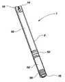
- FIG. 1is a cross-sectional side view of an osmotic agent delivery device including a two-way valve and a dynamically self-adjusting flow channel in a normal condition;
- FIG. 2 ais a cross-sectional side view of an upper section of an osmotic agent delivery device including a two-way valve and a dynamically self-adjusting flow channel, in which the closing member has been axially displaced;
- FIG. 2 bis a cut away view of the valve shown in FIG. 2 a , showing the elongated cylindrical stem.
- FIG. 3is a cross-sectional side view of an upper section of an osmotic agent delivery device including a two-way valve and a dynamically self-adjusting flow channel, in which the closing member has been axially displaced to a greater extent than that shown in FIGS. 2 a and 2 b;
- FIG. 4is a cross-sectional side view of an upper section of an osmotic agent delivery device including a two-way valve and a dynamically self-adjusting flow channel, in which an upper chamber thereof is substantially closed off; and
- FIG. 5is a cross-sectional side view of a two-way valve and a dynamically self-adjusting flow channel, according to a second embodiment of the invention.
- the present inventionrelates to a pressure activated, two-way valve and self-adjusting flow channel for use in regulating fluid flow in an implantable osmotically driven beneficial agent delivery system.
- the components of the two-way valve and self-adjusting flow channelare designed to substantially prevent the passage of interstitial fluid therethrough when the pressure within a beneficial agent reservoir is below a lower predetermined pressure and prevent passage of beneficial agent therethrough when the pressure within a beneficial agent reservoir is above an upper predetermined pressure. This is accomplished by the narrowing of the fluid flow channel when the pressure within the beneficial agent reservoir is either below a lower predetermined pressure or above a higher predetermined pressure.
- the valvecan be designed to close altogether at the orifice end, or it can provide a minimal leak path so that a maximum fluid flow is never exceeded.
- the valveAt zero or very low pressures, the valve will close completely or provide a minimal leak path at the beneficial agent reservoir end, thereby substantially isolating the agent formulation from external fluid infiltration and eliminating diffusion of external fluid into the beneficial agent formulation. While these performance criteria can be achieved with various discrete components (e.g., relief valve, flow restrictor, check valve), this invention combines all the desired performance with a single, simple, and low cost mechanism.
- various discrete componentse.g., relief valve, flow restrictor, check valve
- the present inventionminimizes the error contribution of them by requiring a significant increase in the overall pressure at which the system still dispenses beneficial agent.
- a 0.01 psi (pounds per square inch) pressure increasewill contribute substantially more error to a system dispensing at a nominal pressure of 0.10 psi than a 0.10 psi increase will to a system dispensing at 3 psi (10% vs. 3%).
- FIG. 1illustrates an implantable osmotically driven beneficial agent delivery system 1 having a capsule 2 .
- the capsule 2has an impermeable outer layer and includes a beneficial agent reservoir 50 and an osmotic agent reservoir 52 .
- the beneficial agent delivery system 1also preferably includes a movable piston 54 positioned between the beneficial agent reservoir 50 and the osmotic agent reservoir 52 .
- a fluid permeable membrane 56is provided at the fluid uptake end 16 of the beneficial agent delivery system 1 .
- the fluid permeable membrane 56can be any suitable membrane or combination of membranes in a shape that can adequately control the amount of fluid entering into the capsule 2 . Additionally, the membrane 56 should also be selected to prevent the compositions within the capsule 2 from passing out of the capsule.
- a valve assembly 10is provided at the beneficial agent delivery end 14 of the capsule.
- the capsule 2must be sufficiently strong to ensure that it will not leak, crack, break, or distort so as to expel its beneficial agent contents under stresses it would be subjected to during use while being impermeable. In particular, it should be designed to withstand the maximum osmotic pressure that could be generated by the water-swellable osmotic agent in reservoir 52 .
- Capsule 2must also be chemically inert and biocompatible, that is, it must be non-reactive with the beneficial agent formulation as well as the body. Suitable materials generally comprise a non-reactive polymer or a biocompatible metal or alloy.
- the polymersinclude acrylonitrile polymers such as acrylonitrile-butadiene-styrene terpolymer, and the like; halogenated polymers such as polytetrafluoroethylene, polychlorotrifluoroethylene copolymer tertrafluoroethylene and hexafluoropropylene polyimide; polysulfone; polycarbonate polyethylene; polypropylene; polyvinylchloride-acrylic copolymer; polycarbonate-acrylonitrile-butadiene-styrene; polystyrene; and the like.
- the water vapor transmission rate through compositions useful for forming the reservoirare reported in J. Pharm. Sci ., Vol. 29, pp.
- Metallic materials useful in the inventioninclude stainless steel, titanium, platinum, tantalum, gold and their alloys as well as gold-plated ferrous alloys, platinum-plated ferrous alloys, cobalt-chromium alloys and titanium nitride coated stainless steel.
- a reservoir made from titanium or a titanium alloy having greater than 60%, often greater than 85%, titaniumis particularly preferred for most size-critical applications.
- the osmotic agent reservoir 52may contain any suitable osmotic agent, examples of which include, but are not limited to, a non-volatile water soluble osmagent, an osmopolymer which swells on contact with water, or a mixture of the two.
- a non-volatile water soluble osmagentsuch as sodium chloride with appropriate lubricants, binders, and viscosity modifying agents, such as sodium carboxymethylcellulose or sodium polyacrylate
- Osmotic agentssuch as sodium chloride with appropriate lubricants, binders, and viscosity modifying agents, such as sodium carboxymethylcellulose or sodium polyacrylate can be prepared in various forms.
- Sodium chloride in tablet formis a preferred water swellable agent as described, for example, in U.S. Pat. No. 5,728,396, which is hereby incorporated herein by reference.
- the osmotic agentshould be capable of generating between 0 and 5200 psi.
- Materials for the fluid permeable membrane 56are those that are semipermeable and that can conform to the shape of the reservoir upon wetting and make a water tight seal with the rigid surface of the reservoir.
- the semipermeable membraneexpands as it hydrates when placed in a fluid environment so that a seal is generated between the mating surfaces of the membrane and the reservoir.
- the polymeric materials from which the membrane may be madevary based on the pumping rates and device configuration requirements and include, but are not limited to, plasticized cellulosic materials, enhanced polymethylmethacrylate such as hydroxyethylmethacrylate (HEMA) and elastomeric materials such as polyurethanes and polyamides, polyether-polyamide copolymers, thermoplastic copolyesters and the like. Further semipermeable compositions are described in U.S. Pat. Nos. 5,413,572 and 6,270,787, which are hereby incorporated herein by reference.
- the movable dividing membercan be of any shape that isolates the water-swellable agent from the beneficial agent formulation, including, but not limited to a sheet or a piston 54 .
- the movable dividing memberisolates the water-swellable agent in reservoir 52 from the beneficial agent formulation in reservoir 50 and must be capable of sealably moving under pressure within capsule 2 .
- the movable piston 54is preferably made of a material that is of lower durometer than the capsule 2 and that will deform to fit the interior of the capsule 2 to provide a fluid-tight compression seal with the capsule 2 .
- the materials from which the movable dividing member or piston is madeare preferably elastomeric materials that are impermeable and include, but are not limited to, polypropylene, rubbers such as EPDM, silicone rubber, butyl rubber, and the like, fluoro elastomers, perfluoro elastomers, and thermoplastic elastomers such as plasticized polyvinylchloride, polyurethanes, Santoprene®, C-Flex® TPE, a styrene-ethylene-butylene-styrene copolymer (Consolidated Polymer Technologies Inc.) and the like.
- the movable dividing member, or movable pistonmay be of a compression-loaded design.
- Implantable drug delivery devices of this inventionare useful to deliver a wide variety of active agents. These agents include, but are not limited to, pharmacologically active peptides and proteins, genes and gene products, other gene therapy agents, and other small molecules.
- the polypeptidesmay include, but are not limited to, growth hormone, somatotropin analogues, somatomedin-C, Gonadotropic releasing hormone, follicle stimulating hormone, luteinizing hormone, LHRH, LHRH analogues such as leuprolide, nafarelin and goserelin, LHRH agonists and antagonists, growth hormone releasing factor, calcitonin, colchicine, gonadotropins such as chorionic gonadotropin, oxtocin, octreotide, somatotropin plus an amino acid, vasopressin, adrenocorticotrophic hormone, epidermal growth factor, prolactin, somatostatin, somatotropin
- agents that may be deliveredinclude ⁇ 1 antitrypsin, factor VIII, factor IX and other coagulation factors, insulin and other peptide hormones, adrenal cortical stimulating hormone, thyroid stimulating hormone and other pituitary hormones, interferon including, but not limited to, ⁇ , ⁇ , and ⁇ , erythropoietin, growth factors such GCSF, GMCSF, insulin-like growth factor 1, tissue plasminogen activator, CD4, dDAVP, interleukin-1 receptor antagonist, tumor necrosis factor, pancreatic enzymes, lactase, cytokines, interleukin 2, tumor necrosis factor receptor, tumor suppresser proteins, cytotoxic proteins, and recombinant antibodies and antibody fragments, and the like.
- growth factorssuch GCSF, GMCSF, insulin-like growth factor 1, tissue plasminogen activator, CD4, dDAVP, interleukin-1 receptor antagonist, tumor necrosis factor, pancreatic enzymes, lactase, cytokines, interle
- the above agentsare useful for the treatment of a variety of conditions including, but not limited to, hemophilia and other blood disorders, growth disorders, diabetes, leukemia, hepatitis, renal failure, HIV infection, hereditary diseases such as cerebroside deficiency and adenosine deaminase deficiency, hypertension, septic shock, autoimmune diseases such as multiple sclerosis, Graves disease, systemic lupus erythematosus and rheumatoid arthritis, shock and wasting disorders, cystic fibrosis, lactose intolerance, Crohn's disease, inflammatory bowel disease, and gastrointestinal and other cancers.
- hemophilia and other blood disordersincluding, but not limited to, hemophilia and other blood disorders, growth disorders, diabetes, leukemia, hepatitis, renal failure, HIV infection, hereditary diseases such as cerebroside deficiency and adenosine deaminase deficiency, hypertension, septic
- the active agentsmay be anhydrous or aqueous solutions, suspensions or complexes with pharmaceutically acceptable vehicles or carriers such that a flowable formulation is produced that may be stored for long periods on the shelf or under refrigeration, as well as stored in an implanted delivery system.
- the formulationsmay include pharmaceutically acceptable carriers and additional inert ingredients.
- the active agentsmay be in various forms, such as uncharged molecules, components of molecular complexes or pharmacologically acceptable salts. Also, simple derivatives of the agents (such as prodrugs, ethers, esters, amides, etc.) which are easily hydrolyzed by body pH, enzymes, etc., can be employed.
- valve body halves 30 and 32are preferably made of titanium, steel, and their alloys, thermoplastics including polyether ketone (PEEK) or liquid crystal polymers (LCP) and the like. More preferably valve body halves 30 and 32 are made of a liquid crystal polymer.
- Spring 24is preferably made of spring steels including stainless steel or beryllium/copper or injection molded polymer or plastic.
- the spring materialshould provide dimensionality while having a wire thickness that can be manufactured and inserted into the valve. More preferably spring 24 is made of stainless steel for a fine wire spring or a suitable plastic for a thicker wire spring.
- the profile of spring 24may be round, square, or any other appropriate shape. Spring 24 provides the fluid path from reservoir 50 through upper port 22 .
- Stem 46 and guide post 48may be made of the same materials as valve body halves 30 and 32 , or elastomeric materials such as fluoro elastomers, perfluoro elastomers, thermoplastic elastomers such as C-Flex® or Santoprene®, hard plastics, or the like. Stem 46 and guide post 48 are preferably made of thermoplastic elastomers, perfluoro elastomers, or hard plastic.
- fluid from the exterior of the capsule 2passes through the membrane 56 and into the capsule 2 .
- Some of the fluidis then absorbed by the osmotic agent in reservoir 52 , thereby causing the osmotic agent to swell.
- the osmotic agentswells, the increased volume thereof causes the movable piston 54 to push the beneficial agent housed in the beneficial agent reservoir 50 to be dispensed through the valve assembly 10 and into the patient's body ( FIG. 1 ).
- the beneficial agentis only dispensed through the valve assembly 10 when the pressure within the capsule 2 is greater than a lower predetermined pressure. The mechanics of the valve assembly 10 will be described in greater detail below with reference to FIGS. 1–5 .
- the valve assembly 10includes a valve body 12 containing a plurality of interconnected fluid chambers 60 and 70 .
- the valve assembly 10should have a height measurement larger than the diameter measurement. In other words, the ratio of the height to width of the valve assembly should be greater than 1:1.
- the height to width ratio of the valve assemblyshould be less than 1:5.
- the height to width ratio of the valve assemblyis between 1:1 and 1:2.
- the valve assemblypreferably has a diameter of about 1 to about 10 mm, more preferably about 3 to about 6 mm.
- the valve assemblypreferably has a height of about 5 to about 10 mm.
- the valve body 12preferably includes two identical halves 30 and 32 .
- the valve assembly 10further includes a lower port 20 and an upper port 22 .
- a lower fluid chamber 60is positioned adjacent to and in fluid communication with the lower port 20 .
- An upper fluid chamber 70is positioned between and in fluid communication with the upper port 22 and the lower fluid chamber 60 .
- the lower fluid chamber 60includes a first surface 62 having a conical frustum shape and a second surface 64 having a cylindrical shape.
- the diameter of the lowermost portion of the first surface 62is smaller than the diameter of the lower port 20 .
- the diameter of the uppermost portion of the first surface 62is substantially the same as the diameter of the second surface 64 .
- the lower fluid chamber 60also includes a third surface 66 that is substantially perpendicular to the second surface 64 .
- a passageway 74formed at the intersection of the third surface 66 and the upper fluid chamber 70 , is provided between the upper and lower fluid chambers 70 , 60 .
- the diameter of the upper port 22is substantially smaller than the diameter of the upper fluid chamber 70 and a top surface 72 (also substantially perpendicular to second surface 64 ) is provided therebetween.
- the valve assembly 10contains a movable closing member 40 having a cylindrical seal 44 and a conical frustum 42 attached to an elongated cylindrical stem 46 (shown more clearly in FIG. 2 b ) and a guide post 48 .
- Stem 46is slightly smaller in diameter than spring 24 .
- Guide post 48should have a diameter slightly smaller than the diameter of upper port 22 .
- the movable closing member 40also includes a substantially flat upper surface 90 .
- the closing member 40 and the cylindrical stem 46may be fabricated as a single piece, preferably by molding, or they may be separately fabricated and attached in any known manner. Additionally, the stem 46 may be fabricated with a threaded end that is configured to mate with a threaded opening provided on the upper surface 90 of the closing member 40 .
- the movable closing member 40can be moved from a lowermost position substantially adjacent the first surface 62 to an uppermost position substantially adjacent the third surface 66 .
- the conical frustum 42 of the closing member 40is shaped to substantially mate with the first surface 62 when the closing member 40 is in the lowermost position.
- the upper surface 90 of the closing member 40is also shaped to substantially cover the third surface 66 of the lower fluid chamber 60 when the closing member is in the uppermost position.
- a spring 24is provided around the cylindrical stem 46 and between the top surface 72 and the upper surface 90 .
- the spring 24is preferably a helical compression spring and is shown as such in FIG. 1 . However, it is to be understood that any other suitable spring may be used in place of the helical compression spring.
- the spring 24maintains the closing member 40 in a position to substantially prohibit fluid flow in either direction of the valve assembly 10 .
- Cylindrical seal 44prevents fluid flow across the lower port 20 such that there is substantially no fluid communication between any beneficial agent contained within the beneficial agent reservoir 50 and, once implanted, interstitial fluid present at the upper port 22 .
- movable closing member 40is designed to travel through some predetermined axial displacement while still maintaining a seal at lower port 22 . This occurs because the cylindrical seal 44 has a height that is greater than the height of the lower port 20 . This feature allows the valve assembly 10 to contain the increased agent formulation volume that results from thermal expansion upon implantation without the startup burst that occurs in many devices.
- valve 10The pressure necessary to either keep valve 10 in the closed position (as illustrated in FIGS. 2 and 4 ) or in an open position (as illustrated in FIG. 3 ) is dependent, for example, on the viscosity of the beneficial agent formulation; the desired rate at which the beneficial agent formulation is delivered from the system; the spring constant of spring 24 ; and/or the amount of room spring 24 takes up in valve 10 .
- the psi(pounds per square inch) range from low to high pressure (from valve open to valve closed) needs to be very narrow, but could be anywhere in the range of about 0.1 to about 2000 psi. Preferably the range is about 0.5 to about 100 psi.
- the valve assembly 10is fabricated by positioning the helical compression spring 24 over the cylindrical stem 46 of the movable closing member 40 .
- the assembly 10is subsequently captured between the two valve body halves 30 and 32 with the conical frustum 42 and cylindrical seal 44 oriented to engage the first surface 62 of lower fluid chamber 60 and the lower port 20 , respectively.
- the resulting assemblywill cause the spring 24 to be under a compressive load, forcing the conical frustum 42 to seal against the first surface 62 at lower fluid chamber 60 . Consequently, the valve assembly 10 is normally closed to fluid flow at the lower port 20 .
- the body halves 30 and 32can be sealed together in any of a number of ways known in the art. For example, using adhesives, ultrasonic welding, or mechanical mating.
- FIG. 3illustrates the valve operation once the fluid pressure at the lower port 20 exceeds the minimal value (for example, about 5 psi) as would be the case for normal operation.
- the movable closing member 40will be displaced axially upward toward the upper port 22 , creating an opening at the lower port 20 and allowing the beneficial agent from the beneficial agent reservoir 50 to be pumped through the lower port 20 then through, successively, fluid chambers 60 and 70 , and finally exiting upper port 22 .
- the cross-sectional area of the opening, and thus the fluid flowis directly proportional to the pressure applied by the fluid against the movable closing member 40 until such time as the pressure begins to approach some predetermined maximum value.
- the valve actionis reversed as the upper surface 90 of the closing member 40 approaches the third surface 66 of the lower fluid chamber 60 .
- the spring 24defines a spiral fluid flow path through the upper fluid chamber 70 .
- the spring 24compresses as the movable closing member 40 is forced upward by the flowing agent. Consequently, as the fluid pressure inside the beneficial agent reservoir 50 and the chamber 60 increases, the lower port 20 opens more fully while the fluid flow path progressively narrows, thus becoming more restrictive. Normal flow will cause a balance between the opposing forces of the spring and the fluid pressure while low fluid flow will typically be completely impeded by the compression spring 24 causing lower port 20 to be closed by the movable closing member 40 . On the other hand, high fluid flow will typically be substantially impeded by the upper surface 90 of the movable closing member 40 substantially closing off the passageway 74 . Compression of spring 24 reduces the flow path between lower fluid chamber 60 and upper port 22 .
- FIG. 4shows the valve condition when a maximum pressure is reached (for example, about 20 psi).
- the movable closing member 40has been driven in FIG. 4 to its uppermost position, forcing the movable member against third surface 66 of lower fluid chamber 60 .
- Thisboth limits the travel of the movable closing member 40 and either closes fluid communication between lower fluid chamber 60 and upper fluid chamber 70 , or, in the preferred embodiment, limits the fluid flow around the movable closing member 40 to some predetermined minimal amount via a small fluid bypass channel around movable closing member 40 .
- the fluid pathincreases in cross-sectional area at the third surface 66 , thereby again allowing increased fluid flow. In this manner, fluid flow is continuously regulated to compensate for pressure and temperature variations, which would otherwise cause sub-optimal performance.
- One further embodiment of this inventionincludes a separate small fluid bypass channel that can be formed by either a small hole through movable closing member 40 or a notch formed in one edge of movable closing member 40 .
- FIG. 5illustrates another preferred embodiment of the present invention, in which, a valve assembly 80 can be fabricated as a silicon microstructure or molded in thermoplastic.
- the valve assembly 80includes a single chambered valve body 81 having an integrally formed cantilever spring arm 82 in place of the compression spring described hereinabove.
- the cantilever spring arm 82may be made of metal (such as those described above for valve body halves 30 and 32 ) or a thermoplastic.
- the movable closing member 86is in the form of a spheroid and is attached to the free end of the cantilever spring arm 82 .
- the movable closing member 86may be made of a metal or metal alloy (such as those described above for valve body halves 30 and 32 ), a thermoplastic, or an elastomer.
- the upper and lower ports of this embodimentdo not have to have the same diameter, as long as movable closing member 86 closes off the vertical portion of the upper or lower port when pressure is either lower or higher than a predetermined pressure.
- other shapesmay also be used for the closing member 86 .
- One potential benefitis that this embodiment presents an integral structure rather than an assembly and discrete components. Still another benefit is its extremely small overall size.
Landscapes
- Health & Medical Sciences (AREA)
- Animal Behavior & Ethology (AREA)
- Public Health (AREA)
- Chemical & Material Sciences (AREA)
- Medicinal Chemistry (AREA)
- Pharmacology & Pharmacy (AREA)
- Epidemiology (AREA)
- Veterinary Medicine (AREA)
- Life Sciences & Earth Sciences (AREA)
- General Health & Medical Sciences (AREA)
- Engineering & Computer Science (AREA)
- Bioinformatics & Cheminformatics (AREA)
- Biomedical Technology (AREA)
- Neurosurgery (AREA)
- Dermatology (AREA)
- Infusion, Injection, And Reservoir Apparatuses (AREA)
- Prostheses (AREA)
Abstract
Description
Claims (13)
Priority Applications (2)
| Application Number | Priority Date | Filing Date | Title |
|---|---|---|---|
| US10/302,104US7014636B2 (en) | 2002-11-21 | 2002-11-21 | Osmotic delivery device having a two-way valve and a dynamically self-adjusting flow channel |
| US11/237,489US7316680B2 (en) | 2002-11-21 | 2005-09-27 | Osmotic delivery device having a two-way valve and a dynamically self-adjusting flow channel |
Applications Claiming Priority (1)
| Application Number | Priority Date | Filing Date | Title |
|---|---|---|---|
| US10/302,104US7014636B2 (en) | 2002-11-21 | 2002-11-21 | Osmotic delivery device having a two-way valve and a dynamically self-adjusting flow channel |
Related Child Applications (1)
| Application Number | Title | Priority Date | Filing Date |
|---|---|---|---|
| US11/237,489DivisionUS7316680B2 (en) | 2002-11-21 | 2005-09-27 | Osmotic delivery device having a two-way valve and a dynamically self-adjusting flow channel |
Publications (2)
| Publication Number | Publication Date |
|---|---|
| US20040102762A1 US20040102762A1 (en) | 2004-05-27 |
| US7014636B2true US7014636B2 (en) | 2006-03-21 |
Family
ID=32324681
Family Applications (2)
| Application Number | Title | Priority Date | Filing Date |
|---|---|---|---|
| US10/302,104Expired - LifetimeUS7014636B2 (en) | 2002-11-21 | 2002-11-21 | Osmotic delivery device having a two-way valve and a dynamically self-adjusting flow channel |
| US11/237,489Expired - LifetimeUS7316680B2 (en) | 2002-11-21 | 2005-09-27 | Osmotic delivery device having a two-way valve and a dynamically self-adjusting flow channel |
Family Applications After (1)
| Application Number | Title | Priority Date | Filing Date |
|---|---|---|---|
| US11/237,489Expired - LifetimeUS7316680B2 (en) | 2002-11-21 | 2005-09-27 | Osmotic delivery device having a two-way valve and a dynamically self-adjusting flow channel |
Country Status (1)
| Country | Link |
|---|---|
| US (2) | US7014636B2 (en) |
Cited By (49)
| Publication number | Priority date | Publication date | Assignee | Title |
|---|---|---|---|---|
| US20040254544A1 (en)* | 2003-06-12 | 2004-12-16 | Russell Scott M. | Orifice device for delivering drugs at low fluid flow rates |
| US20040254564A1 (en)* | 2003-06-12 | 2004-12-16 | Russell Scott M. | Medical device for fluid delivery having low fluid flow rate |
| US20040267241A1 (en)* | 2003-06-12 | 2004-12-30 | Russell Scott M. | Orifice device having multiple channels and multiple layers for drug delivery |
| US20050004557A1 (en)* | 2003-06-12 | 2005-01-06 | Russell Scott M. | Orifice device having multiple channels with varying flow rates for drug delivery |
| US20050010196A1 (en)* | 2003-03-31 | 2005-01-13 | Fereira Pamela J. | Osmotic delivery system and method for decreasing start-up times for osmotic delivery systems |
| US20050101943A1 (en)* | 2003-11-06 | 2005-05-12 | Alza Corporation | Modular imbibition rate reducer for use with implantable osmotic pump |
| US20050112188A1 (en)* | 2003-11-17 | 2005-05-26 | Eliaz Rom E. | Composition and dosage form comprising an amphiphilic molecule as a suspension vehicle |
| US20060099263A1 (en)* | 1993-05-27 | 2006-05-11 | Edgren David E | Antidepressant dosage form |
| US20060184158A1 (en)* | 2002-06-17 | 2006-08-17 | Fereira Pamela J | Osmotic delivery system with early zero order push power engine |
| US20060246138A1 (en)* | 2005-03-15 | 2006-11-02 | Rohloff Catherine M | Polyoxaester suspending vehicles for use with implantable delivery systems |
| US20060251618A1 (en)* | 2005-02-03 | 2006-11-09 | Paula Dennis | Implantable device for continuous delivery of interferon |
| US20070003598A1 (en)* | 2003-08-06 | 2007-01-04 | Warsaw Orthopedic, Inc. | Osteogenic implants for soft tissue |
| US20070191818A1 (en)* | 2003-03-31 | 2007-08-16 | Dionne Keith E | Osmotic pump with means for dissipating internal pressure |
| US20070250046A1 (en)* | 2006-04-24 | 2007-10-25 | Sdgi Holdings, Inc. | Controlled release devices for therapeutic treatments of spinal discs |
| US20070250045A1 (en)* | 2006-04-24 | 2007-10-25 | Warsaw Orthopedic, Inc. | Controlled release systems and methods for osteal growth |
| US20070276337A1 (en)* | 2006-04-24 | 2007-11-29 | Warsaw Orthopedic, Inc. | Controlled release devices for fusion of osteal structures |
| US20070281024A1 (en)* | 2005-02-03 | 2007-12-06 | Alza Corporation | Two-Piece, Internal-Channel Osmotic Delivery System Flow Modulator |
| US20080055036A1 (en)* | 2006-08-29 | 2008-03-06 | International Business Machines Corporation | Electrical component tuned by conductive layer deletion |
| US20080071253A1 (en)* | 1997-07-25 | 2008-03-20 | Alza Corporation | Osmotic Delivery System Flow Modulator Apparatus and Method |
| US20080091176A1 (en)* | 2006-08-09 | 2008-04-17 | Alessi Thomas R | Osmotic delivery systems and piston assemblies for use therein |
| US20080112994A1 (en)* | 2004-05-25 | 2008-05-15 | Intarcia Therapeutics, Inc. | Formulations having increased stability during transition from hydrophobic vehicle to hydrophilic medium |
| US20080226625A1 (en)* | 1999-02-08 | 2008-09-18 | Intarcia Therapeutics, Inc. | Stable non- aqueous single phase viscous vehicles and formulations utlizing such vehicles |
| US20080226689A1 (en)* | 1999-02-08 | 2008-09-18 | Intarcia Therapeutics, Inc. | Stable non-aqueous single phase viscous vehicles and formulations utilizing such vehicles |
| US20080260840A1 (en)* | 2005-02-03 | 2008-10-23 | Alessi Thomas R | Suspension formulations of insulinotropic peptides and uses thereof |
| US20090087408A1 (en)* | 2002-12-19 | 2009-04-02 | Intarcia Therapeutics, Inc. | Stable, non-aqueous, single-phase gels and formulations thereof for delivery from an implantable device |
| US20090202608A1 (en)* | 2008-02-13 | 2009-08-13 | Alessi Thomas R | Devices, formulations, and methods for delivery of multiple beneficial agents |
| US20100092566A1 (en)* | 2008-10-15 | 2010-04-15 | Alessi Thomas R | Highly concentrated drug particles, formulations, suspensions and uses thereof |
| US20110076317A1 (en)* | 2009-09-28 | 2011-03-31 | Alessi Thomas R | Rapid establishment and/or termination of substantial steady-state drug delivery |
| US8114437B2 (en) | 2005-02-03 | 2012-02-14 | Intarcia Therapeutics, Inc. | Solvent/polymer solutions as suspension vehicles |
| US8642059B2 (en) | 2006-04-24 | 2014-02-04 | Warsaw Orthopedic, Inc. | Controlled release systems and methods for intervertebral discs |
| US8820871B2 (en) | 2010-10-27 | 2014-09-02 | Matthews Resources, Inc. | Valve jet printer with inert plunger tip |
| US9138569B2 (en) | 2012-02-29 | 2015-09-22 | SinuSys Corporation | Devices and methods for dilating a paranasal sinus opening and for treating sinusitis |
| US9498239B2 (en) | 2010-08-30 | 2016-11-22 | SinuSys Corporation | Devices and methods for inserting a sinus dilator |
| WO2017079467A1 (en) | 2015-11-05 | 2017-05-11 | The General Hospital Corporation | Intrathecal delivery of nucleic acid sequences encoding abcd1 for treatment of adrenomyeloneuropathy |
| US9687263B2 (en) | 2013-05-30 | 2017-06-27 | SinuSys Corporation | Devices and methods for inserting a sinus dilator |
| US9889085B1 (en) | 2014-09-30 | 2018-02-13 | Intarcia Therapeutics, Inc. | Therapeutic methods for the treatment of diabetes and related conditions for patients with high baseline HbA1c |
| WO2018075901A1 (en) | 2016-10-20 | 2018-04-26 | Peptron, Inc. | Methods of delivering a neuroprotective polypeptide to the central nervous system |
| WO2018165462A1 (en) | 2017-03-08 | 2018-09-13 | Intarcia Therapeutics, Inc | Apparatus and methods for administration of a nauseogenic compound from a drug delivery device |
| USD835783S1 (en) | 2016-06-02 | 2018-12-11 | Intarcia Therapeutics, Inc. | Implant placement guide |
| US10159714B2 (en) | 2011-02-16 | 2018-12-25 | Intarcia Therapeutics, Inc. | Compositions, devices and methods of use thereof for the treatment of cancers |
| US10406336B2 (en) | 2016-08-03 | 2019-09-10 | Neil S. Davey | Adjustable rate drug delivery implantable device |
| USD860451S1 (en) | 2016-06-02 | 2019-09-17 | Intarcia Therapeutics, Inc. | Implant removal tool |
| US10501517B2 (en) | 2016-05-16 | 2019-12-10 | Intarcia Therapeutics, Inc. | Glucagon-receptor selective polypeptides and methods of use thereof |
| WO2020077129A1 (en) | 2018-10-11 | 2020-04-16 | Intarcia Therapeutics, Inc. | Human amylin analog polypeptides and methods of use |
| US10835580B2 (en) | 2017-01-03 | 2020-11-17 | Intarcia Therapeutics, Inc. | Methods comprising continuous administration of a GLP-1 receptor agonist and co-administration of a drug |
| US10925639B2 (en) | 2015-06-03 | 2021-02-23 | Intarcia Therapeutics, Inc. | Implant placement and removal systems |
| USD933219S1 (en) | 2018-07-13 | 2021-10-12 | Intarcia Therapeutics, Inc. | Implant removal tool and assembly |
| US11246913B2 (en) | 2005-02-03 | 2022-02-15 | Intarcia Therapeutics, Inc. | Suspension formulation comprising an insulinotropic peptide |
| WO2025160155A1 (en) | 2024-01-22 | 2025-07-31 | The Broad Institute, Inc. | Epigenetic targeting of prion diseases |
Families Citing this family (15)
| Publication number | Priority date | Publication date | Assignee | Title |
|---|---|---|---|---|
| US7163688B2 (en)* | 2001-06-22 | 2007-01-16 | Alza Corporation | Osmotic implant with membrane and membrane retention means |
| US20060037617A1 (en)* | 2004-04-19 | 2006-02-23 | Walke Amrish J | Airway implant devices and methods of use |
| US20060077779A1 (en)* | 2004-09-03 | 2006-04-13 | Benq Corporation | Optical pickup device with elastic member |
| US10208158B2 (en) | 2006-07-10 | 2019-02-19 | Medipacs, Inc. | Super elastic epoxy hydrogel |
| US8181708B2 (en)* | 2007-10-01 | 2012-05-22 | Baker Hughes Incorporated | Water swelling rubber compound for use in reactive packers and other downhole tools |
| JP2011505520A (en) | 2007-12-03 | 2011-02-24 | メディパックス インコーポレイテッド | Fluid metering device |
| WO2011032011A1 (en) | 2009-09-10 | 2011-03-17 | Medipacs, Inc. | Low profile actuator and improved method of caregiver controlled administration of therapeutics |
| US20110172637A1 (en)* | 2010-01-08 | 2011-07-14 | Ratio, Inc. | Drug delivery device including tissue support structure |
| US20110172639A1 (en)* | 2010-01-08 | 2011-07-14 | Ratio, Inc. | Device and method for delivery of microneedle to desired depth within the skin |
| US20110172609A1 (en)* | 2010-01-08 | 2011-07-14 | Ratio, Inc. | Microneedle component assembly for drug delivery device |
| US20110172645A1 (en)* | 2010-01-08 | 2011-07-14 | Ratio, Inc. | Wearable drug delivery device including integrated pumping and activation elements |
| US9500186B2 (en) | 2010-02-01 | 2016-11-22 | Medipacs, Inc. | High surface area polymer actuator with gas mitigating components |
| WO2012061556A1 (en) | 2010-11-03 | 2012-05-10 | Flugen, Inc. | Wearable drug delivery device having spring drive and sliding actuation mechanism |
| US10000605B2 (en) | 2012-03-14 | 2018-06-19 | Medipacs, Inc. | Smart polymer materials with excess reactive molecules |
| US10173004B2 (en) | 2013-01-08 | 2019-01-08 | Flowonix Medical Incorporated | Flow actuated valve for implantable drug delivery device |
Citations (23)
| Publication number | Priority date | Publication date | Assignee | Title |
|---|---|---|---|---|
| FR640907A (en) | 1927-06-25 | 1928-07-24 | Automatic flow limiter | |
| US3122162A (en) | 1963-06-20 | 1964-02-25 | Asa D Sands | Flow control device |
| US3987790A (en) | 1975-10-01 | 1976-10-26 | Alza Corporation | Osmotically driven fluid dispenser |
| US4865845A (en) | 1986-03-21 | 1989-09-12 | Alza Corporation | Release rate adjustment of osmotic or diffusional delivery devices |
| US5059423A (en) | 1988-12-13 | 1991-10-22 | Alza Corporation | Delivery system comprising biocompatible beneficial agent formulation |
| US5112614A (en) | 1989-09-14 | 1992-05-12 | Alza Corporation | Implantable delivery dispenser |
| US5137727A (en) | 1991-06-12 | 1992-08-11 | Alza Corporation | Delivery device providing beneficial agent stability |
| US5213809A (en) | 1990-01-24 | 1993-05-25 | Alza Corporation | Delivery system comprising means for controlling internal pressure |
| US5221278A (en) | 1992-03-12 | 1993-06-22 | Alza Corporation | Osmotically driven delivery device with expandable orifice for pulsatile delivery effect |
| US5234693A (en) | 1990-07-11 | 1993-08-10 | Alza Corporation | Delivery device with a protective sleeve |
| US5234692A (en) | 1990-07-11 | 1993-08-10 | Alza Corporation | Delivery device with a protective sleeve |
| US5308348A (en) | 1992-02-18 | 1994-05-03 | Alza Corporation | Delivery devices with pulsatile effect |
| US5413572A (en) | 1990-04-02 | 1995-05-09 | Alza Corporation | Osmotic dosage system for liquid drug delivery |
| US5514110A (en) | 1993-03-22 | 1996-05-07 | Teh; Eutiquio L. | Automatic flow control device |
| US5540665A (en) | 1994-01-31 | 1996-07-30 | Alza Corporation | Gas driven dispensing device and gas generating engine therefor |
| WO1997047339A1 (en) | 1996-06-14 | 1997-12-18 | Filtertek, S.A. | Gravity infusion set for medical infusions |
| US5728396A (en) | 1996-02-02 | 1998-03-17 | Alza Corporation | Sustained delivery of leuprolide using an implantable system |
| US5997527A (en)* | 1997-03-24 | 1999-12-07 | Alza Corporation | Self adjustable exit port |
| US6183461B1 (en) | 1998-03-11 | 2001-02-06 | Situs Corporation | Method for delivering a medication |
| US6270787B1 (en) | 1997-12-29 | 2001-08-07 | Alza Corporation | Osmotic delivery system with membrane plug retention mechanism |
| US6508808B1 (en)* | 1999-12-21 | 2003-01-21 | Alza Corporation | Valve for osmotic devices |
| US20030097121A1 (en)* | 2001-10-24 | 2003-05-22 | Claude Jolly | Implantable fluid delivery apparatuses and implantable electrode |
| US6835194B2 (en)* | 1999-03-18 | 2004-12-28 | Durect Corporation | Implantable devices and methods for treatment of pain by delivery of fentanyl and fentanyl congeners |
- 2002
- 2002-11-21USUS10/302,104patent/US7014636B2/ennot_activeExpired - Lifetime
- 2005
- 2005-09-27USUS11/237,489patent/US7316680B2/ennot_activeExpired - Lifetime
Patent Citations (24)
| Publication number | Priority date | Publication date | Assignee | Title |
|---|---|---|---|---|
| FR640907A (en) | 1927-06-25 | 1928-07-24 | Automatic flow limiter | |
| US3122162A (en) | 1963-06-20 | 1964-02-25 | Asa D Sands | Flow control device |
| US3987790A (en) | 1975-10-01 | 1976-10-26 | Alza Corporation | Osmotically driven fluid dispenser |
| US4865845A (en) | 1986-03-21 | 1989-09-12 | Alza Corporation | Release rate adjustment of osmotic or diffusional delivery devices |
| US5059423A (en) | 1988-12-13 | 1991-10-22 | Alza Corporation | Delivery system comprising biocompatible beneficial agent formulation |
| US5112614A (en) | 1989-09-14 | 1992-05-12 | Alza Corporation | Implantable delivery dispenser |
| US5213809A (en) | 1990-01-24 | 1993-05-25 | Alza Corporation | Delivery system comprising means for controlling internal pressure |
| US5413572A (en) | 1990-04-02 | 1995-05-09 | Alza Corporation | Osmotic dosage system for liquid drug delivery |
| US5234692A (en) | 1990-07-11 | 1993-08-10 | Alza Corporation | Delivery device with a protective sleeve |
| US5234693A (en) | 1990-07-11 | 1993-08-10 | Alza Corporation | Delivery device with a protective sleeve |
| US5137727A (en) | 1991-06-12 | 1992-08-11 | Alza Corporation | Delivery device providing beneficial agent stability |
| US5308348A (en) | 1992-02-18 | 1994-05-03 | Alza Corporation | Delivery devices with pulsatile effect |
| US5221278A (en) | 1992-03-12 | 1993-06-22 | Alza Corporation | Osmotically driven delivery device with expandable orifice for pulsatile delivery effect |
| US5514110A (en) | 1993-03-22 | 1996-05-07 | Teh; Eutiquio L. | Automatic flow control device |
| US5540665A (en) | 1994-01-31 | 1996-07-30 | Alza Corporation | Gas driven dispensing device and gas generating engine therefor |
| US5985305A (en) | 1996-02-02 | 1999-11-16 | Alza Corporation | Sustained delivery of an active agent using an implantable system |
| US5728396A (en) | 1996-02-02 | 1998-03-17 | Alza Corporation | Sustained delivery of leuprolide using an implantable system |
| WO1997047339A1 (en) | 1996-06-14 | 1997-12-18 | Filtertek, S.A. | Gravity infusion set for medical infusions |
| US5997527A (en)* | 1997-03-24 | 1999-12-07 | Alza Corporation | Self adjustable exit port |
| US6270787B1 (en) | 1997-12-29 | 2001-08-07 | Alza Corporation | Osmotic delivery system with membrane plug retention mechanism |
| US6183461B1 (en) | 1998-03-11 | 2001-02-06 | Situs Corporation | Method for delivering a medication |
| US6835194B2 (en)* | 1999-03-18 | 2004-12-28 | Durect Corporation | Implantable devices and methods for treatment of pain by delivery of fentanyl and fentanyl congeners |
| US6508808B1 (en)* | 1999-12-21 | 2003-01-21 | Alza Corporation | Valve for osmotic devices |
| US20030097121A1 (en)* | 2001-10-24 | 2003-05-22 | Claude Jolly | Implantable fluid delivery apparatuses and implantable electrode |
Non-Patent Citations (7)
| Title |
|---|
| Ann. Book of ASTM Stds., vol. 8.02, pp. 208-211 and pp. 584-587 (1984). |
| International Search Report dated Aug. 07, 2003 (7 pages). |
| Kildsig et al., "Theoretical Justification of Reciprocal Rate Plots in Studies of Water Vapor Transmission through Films," J. Pharm. Sci., vol. 29, pp. 1634-1637 (1970). |
| Mohler, J.B., "Primer on electrodeposited coatings," Materials Engineering, vol. 5, pp. 38-45 (1972). |
| Morgan, P.W., "Structure and Moisture Permeability of Film-Forming Polymers," Ind. and Eng. Chem., vol. 45, pp. 2296-2306 (1953). |
| Roff, et al., "Handbook of Common Polymers," CRC Press, Cleveland Rubber Co., Cleveland, Ohio (72 total pages) (1971). |
| Rogers et al., "Permeability Valves; Permeability of Gases and Vapors through Composite Membranes," Ind. and Eng. Chem., vol. 49, pp. 1933-1936 (1957). |
Cited By (132)
| Publication number | Priority date | Publication date | Assignee | Title |
|---|---|---|---|---|
| US20060099263A1 (en)* | 1993-05-27 | 2006-05-11 | Edgren David E | Antidepressant dosage form |
| US20080071253A1 (en)* | 1997-07-25 | 2008-03-20 | Alza Corporation | Osmotic Delivery System Flow Modulator Apparatus and Method |
| US20080226625A1 (en)* | 1999-02-08 | 2008-09-18 | Intarcia Therapeutics, Inc. | Stable non- aqueous single phase viscous vehicles and formulations utlizing such vehicles |
| US7919109B2 (en) | 1999-02-08 | 2011-04-05 | Intarcia Therapeutics, Inc. | Stable non-aqueous single phase viscous vehicles and formulations utilizing such vehicles |
| US8048438B2 (en) | 1999-02-08 | 2011-11-01 | Intarcia Therapeutics, Inc. | Stable non- aqueous single phase viscous vehicles and formulations utilizing such vehicles |
| US8173150B2 (en) | 1999-02-08 | 2012-05-08 | Intarcia Therapeutics, Inc. | Stable non-aqueous single phase viscous vehicles and formulations utlizing such vehicles |
| US8372424B2 (en) | 1999-02-08 | 2013-02-12 | Intarcia Therapeutics, Inc. | Stable non-aqueous single phase viscous vehicles and formulations utilizing such vehicles |
| US8268341B2 (en) | 1999-02-08 | 2012-09-18 | Intarcia Therapeutics, Inc. | Stable non-aqueous single phase viscous vehicles and formulations utilizing such vehicles |
| US8992961B2 (en) | 1999-02-08 | 2015-03-31 | Intarcia Therapeutics, Inc. | Stable non-aqueous single phase viscous vehicles and formulations utilizing such vehicles |
| US20080226689A1 (en)* | 1999-02-08 | 2008-09-18 | Intarcia Therapeutics, Inc. | Stable non-aqueous single phase viscous vehicles and formulations utilizing such vehicles |
| US20060184158A1 (en)* | 2002-06-17 | 2006-08-17 | Fereira Pamela J | Osmotic delivery system with early zero order push power engine |
| US20090087408A1 (en)* | 2002-12-19 | 2009-04-02 | Intarcia Therapeutics, Inc. | Stable, non-aqueous, single-phase gels and formulations thereof for delivery from an implantable device |
| US8398967B2 (en) | 2002-12-19 | 2013-03-19 | Intarcia Therapeutics, Inc. | Particle formulations for use in pharmaceutical compositions |
| US20110208168A1 (en)* | 2002-12-19 | 2011-08-25 | Intarcia Therapeutics, Inc. | Particle formulations for use in pharmaceutical compositions |
| US20050010196A1 (en)* | 2003-03-31 | 2005-01-13 | Fereira Pamela J. | Osmotic delivery system and method for decreasing start-up times for osmotic delivery systems |
| US20070191818A1 (en)* | 2003-03-31 | 2007-08-16 | Dionne Keith E | Osmotic pump with means for dissipating internal pressure |
| US8491571B2 (en) | 2003-06-12 | 2013-07-23 | Cordis Corporation | Orifice device having multiple channels with varying flow rates for drug delivery |
| US20050004557A1 (en)* | 2003-06-12 | 2005-01-06 | Russell Scott M. | Orifice device having multiple channels with varying flow rates for drug delivery |
| US20040254564A1 (en)* | 2003-06-12 | 2004-12-16 | Russell Scott M. | Medical device for fluid delivery having low fluid flow rate |
| US20040254544A1 (en)* | 2003-06-12 | 2004-12-16 | Russell Scott M. | Orifice device for delivering drugs at low fluid flow rates |
| US20040267241A1 (en)* | 2003-06-12 | 2004-12-30 | Russell Scott M. | Orifice device having multiple channels and multiple layers for drug delivery |
| US7211076B2 (en)* | 2003-06-12 | 2007-05-01 | Cordis Corporation | Medical device for fluid delivery having low fluid flow rate |
| US8109922B2 (en) | 2003-06-12 | 2012-02-07 | Cordis Corporation | Orifice device having multiple channels and multiple layers for drug delivery |
| US7678103B2 (en)* | 2003-06-12 | 2010-03-16 | Cordis Corporation | Orifice device for delivering drugs at low fluid flow rates |
| US20070003598A1 (en)* | 2003-08-06 | 2007-01-04 | Warsaw Orthopedic, Inc. | Osteogenic implants for soft tissue |
| US8920828B2 (en) | 2003-08-06 | 2014-12-30 | Warsaw Orthopedic, Inc. | Implants for treatment of symptomatic or degenerated intervertebral discs |
| US20070128575A1 (en)* | 2003-08-06 | 2007-06-07 | Trieu Hai H | Implantable devices for chemonucleolysis of intervertebral discs |
| US20070122446A1 (en)* | 2003-08-06 | 2007-05-31 | Trieu Hai H | Implants for treatment of symptomatic or degenerated intervertebral discs |
| US9061064B2 (en) | 2003-08-06 | 2015-06-23 | Warsaw Orthopedic, Inc. | Implantable devices for chemonucleolysis of intervertebral discs |
| US20050101943A1 (en)* | 2003-11-06 | 2005-05-12 | Alza Corporation | Modular imbibition rate reducer for use with implantable osmotic pump |
| US8257691B2 (en) | 2003-11-17 | 2012-09-04 | Intarcia Therapeutics, Inc. | Composition and dosage form comprising a particle formulation and suspending vehicle |
| US9724293B2 (en) | 2003-11-17 | 2017-08-08 | Intarcia Therapeutics, Inc. | Methods of manufacturing viscous liquid pharmaceutical formulations |
| US20100112070A1 (en)* | 2003-11-17 | 2010-05-06 | Intarcia Therapeutics, Inc. | Composition and dosage form comprising a particle formulation and suspending vehicle |
| US7731947B2 (en) | 2003-11-17 | 2010-06-08 | Intarcia Therapeutics, Inc. | Composition and dosage form comprising an interferon particle formulation and suspending vehicle |
| US20050112188A1 (en)* | 2003-11-17 | 2005-05-26 | Eliaz Rom E. | Composition and dosage form comprising an amphiphilic molecule as a suspension vehicle |
| US20110195097A1 (en)* | 2003-11-17 | 2011-08-11 | Intarcia Therapeutics, Inc. | Composition and dosage form comprising a particle formulation and suspending vehicle |
| US7964183B2 (en) | 2003-11-17 | 2011-06-21 | Intarcia Therapeutics, Inc. | Composition and dosage form comprising a particle formulation and suspending vehicle |
| US20080112994A1 (en)* | 2004-05-25 | 2008-05-15 | Intarcia Therapeutics, Inc. | Formulations having increased stability during transition from hydrophobic vehicle to hydrophilic medium |
| US8440226B2 (en) | 2005-02-03 | 2013-05-14 | Intarcia Therapeutics, Inc. | Solvent/polymer solutions as suspension vehicles |
| US8460694B2 (en) | 2005-02-03 | 2013-06-11 | Intarcia Therapeutics, Inc. | Solvent/polymer solutions as suspension vehicles |
| US9682127B2 (en) | 2005-02-03 | 2017-06-20 | Intarcia Therapeutics, Inc. | Osmotic delivery device comprising an insulinotropic peptide and uses thereof |
| US10363287B2 (en) | 2005-02-03 | 2019-07-30 | Intarcia Therapeutics, Inc. | Method of manufacturing an osmotic delivery device |
| US9539200B2 (en) | 2005-02-03 | 2017-01-10 | Intarcia Therapeutics Inc. | Two-piece, internal-channel osmotic delivery system flow modulator |
| US9526763B2 (en) | 2005-02-03 | 2016-12-27 | Intarcia Therapeutics Inc. | Solvent/polymer solutions as suspension vehicles |
| US11246913B2 (en) | 2005-02-03 | 2022-02-15 | Intarcia Therapeutics, Inc. | Suspension formulation comprising an insulinotropic peptide |
| US9095553B2 (en) | 2005-02-03 | 2015-08-04 | Intarcia Therapeutics Inc. | Solvent/polymer solutions as suspension vehicles |
| US20060251618A1 (en)* | 2005-02-03 | 2006-11-09 | Paula Dennis | Implantable device for continuous delivery of interferon |
| US8992962B2 (en) | 2005-02-03 | 2015-03-31 | Intarcia Therapeutics Inc. | Two-piece, internal-channel osmotic delivery system flow modulator |
| US8940316B2 (en) | 2005-02-03 | 2015-01-27 | Intarcia Therapeutics, Inc. | Osmotic delivery comprising an insulinotropic peptide and uses thereof |
| US8052996B2 (en) | 2005-02-03 | 2011-11-08 | Intarcia Therapeutics, Inc. | Two-piece, internal-channel osmotic delivery system flow modulator |
| US8470353B2 (en) | 2005-02-03 | 2013-06-25 | Intarcia Therapeutics, Inc. | Two-piece, internal-channel osmotic delivery system flow modulator |
| US8114437B2 (en) | 2005-02-03 | 2012-02-14 | Intarcia Therapeutics, Inc. | Solvent/polymer solutions as suspension vehicles |
| US20070281024A1 (en)* | 2005-02-03 | 2007-12-06 | Alza Corporation | Two-Piece, Internal-Channel Osmotic Delivery System Flow Modulator |
| US8158150B2 (en) | 2005-02-03 | 2012-04-17 | Intarcia Therapeutics, Inc. | Two-piece, internal-channel osmotic delivery system flow modulator |
| US7655254B2 (en) | 2005-02-03 | 2010-02-02 | Intarcia Therapeutics, Inc. | Implantable device for continuous delivery of interferon |
| US8206745B2 (en) | 2005-02-03 | 2012-06-26 | Intarcia Therapeutics, Inc. | Solvent/polymer solutions as suspension vehicles |
| US8211467B2 (en) | 2005-02-03 | 2012-07-03 | Intarcia Therapeutics, Inc. | Osmotic drug delivery devices containing suspension formulations comprising particles having active agents and nonaqueous single-phase vehicles |
| US8367095B2 (en) | 2005-02-03 | 2013-02-05 | Intarcia Therapeutics, Inc. | Two-piece, internal-channel osmotic delivery system flow modulator |
| US20080260840A1 (en)* | 2005-02-03 | 2008-10-23 | Alessi Thomas R | Suspension formulations of insulinotropic peptides and uses thereof |
| US8273365B2 (en) | 2005-02-03 | 2012-09-25 | Intarcia Therapeutics, Inc. | Two-piece, internal-channel osmotic delivery system flow modulator |
| US8299025B2 (en) | 2005-02-03 | 2012-10-30 | Intarcia Therapeutics, Inc. | Suspension formulations of insulinotropic peptides and uses thereof |
| US8114430B2 (en) | 2005-03-15 | 2012-02-14 | Intarcia Therapeutics, Inc. | Polyoxaester suspending vehicles for use with implantable delivery systems |
| US7959938B2 (en) | 2005-03-15 | 2011-06-14 | Intarcia Therapeutics, Inc. | Polyoxaester suspending vehicles for use with implantable delivery systems |
| US20060246138A1 (en)* | 2005-03-15 | 2006-11-02 | Rohloff Catherine M | Polyoxaester suspending vehicles for use with implantable delivery systems |
| US20070250046A1 (en)* | 2006-04-24 | 2007-10-25 | Sdgi Holdings, Inc. | Controlled release devices for therapeutic treatments of spinal discs |
| US8642059B2 (en) | 2006-04-24 | 2014-02-04 | Warsaw Orthopedic, Inc. | Controlled release systems and methods for intervertebral discs |
| US7879027B2 (en) | 2006-04-24 | 2011-02-01 | Warsaw Orthopedic, Inc. | Controlled release devices for fusion of osteal structures |
| US7771414B2 (en) | 2006-04-24 | 2010-08-10 | Warsaw Orthopedic, Inc. | Controlled release devices for therapeutic treatments of spinal discs |
| US20070250045A1 (en)* | 2006-04-24 | 2007-10-25 | Warsaw Orthopedic, Inc. | Controlled release systems and methods for osteal growth |
| US20070276337A1 (en)* | 2006-04-24 | 2007-11-29 | Warsaw Orthopedic, Inc. | Controlled release devices for fusion of osteal structures |
| US8642060B2 (en) | 2006-04-24 | 2014-02-04 | Warsaw Orthopedic, Inc. | Controlled release systems and methods for osteal growth |
| EP2359808A1 (en) | 2006-08-09 | 2011-08-24 | Intarcia Therapeutics, Inc | Osmotic delivery systems and piston assemblies |
| US7879028B2 (en) | 2006-08-09 | 2011-02-01 | Intarcia Therapeutics, Inc. | Osmotic delivery systems and piston assemblies for use therein |
| US20080091176A1 (en)* | 2006-08-09 | 2008-04-17 | Alessi Thomas R | Osmotic delivery systems and piston assemblies for use therein |
| US7682356B2 (en) | 2006-08-09 | 2010-03-23 | Intarcia Therapeutics, Inc. | Osmotic delivery systems and piston assemblies for use therein |
| EP3421031A1 (en) | 2006-08-09 | 2019-01-02 | Intarcia Therapeutics, Inc | Osmotic delivery systems and piston assemblies |
| US8801700B2 (en) | 2006-08-09 | 2014-08-12 | Intarcia Therapeutics, Inc. | Osmotic delivery systems and piston assemblies for use therein |
| US20110166554A1 (en)* | 2006-08-09 | 2011-07-07 | Intarcia Therapeutics, Inc. | Osmotic delivery systems and piston assemblies for use therein |
| US10527170B2 (en) | 2006-08-09 | 2020-01-07 | Intarcia Therapeutics, Inc. | Osmotic delivery systems and piston assemblies for use therein |
| EP2363112A2 (en) | 2006-08-09 | 2011-09-07 | Intarcia Therapeutics, Inc | Osmotic delivery systems and piston assemblies |
| US20100185184A1 (en)* | 2006-08-09 | 2010-07-22 | Intarcia Therapeutics, Inc. | Osmotic delivery systems and piston assemblies for use therein |
| US20080055036A1 (en)* | 2006-08-29 | 2008-03-06 | International Business Machines Corporation | Electrical component tuned by conductive layer deletion |
| US20090202608A1 (en)* | 2008-02-13 | 2009-08-13 | Alessi Thomas R | Devices, formulations, and methods for delivery of multiple beneficial agents |
| US8926595B2 (en) | 2008-02-13 | 2015-01-06 | Intarcia Therapeutics, Inc. | Devices, formulations, and methods for delivery of multiple beneficial agents |
| US8343140B2 (en) | 2008-02-13 | 2013-01-01 | Intarcia Therapeutics, Inc. | Devices, formulations, and methods for delivery of multiple beneficial agents |
| US10441528B2 (en) | 2008-02-13 | 2019-10-15 | Intarcia Therapeutics, Inc. | Devices, formulations, and methods for delivery of multiple beneficial agents |
| US9572889B2 (en) | 2008-02-13 | 2017-02-21 | Intarcia Therapeutics, Inc. | Devices, formulations, and methods for delivery of multiple beneficial agents |
| US20100092566A1 (en)* | 2008-10-15 | 2010-04-15 | Alessi Thomas R | Highly concentrated drug particles, formulations, suspensions and uses thereof |
| US8298561B2 (en) | 2009-09-28 | 2012-10-30 | Intarcia Therapeutics, Inc. | Rapid establishment and/or termination of substantial steady-state drug delivery |
| US20110076317A1 (en)* | 2009-09-28 | 2011-03-31 | Alessi Thomas R | Rapid establishment and/or termination of substantial steady-state drug delivery |
| EP3735944A1 (en) | 2009-09-28 | 2020-11-11 | Intarcia Therapeutics, Inc. | Rapid establishment and/or termination of substantial steady-state drug delivery |
| US10231923B2 (en) | 2009-09-28 | 2019-03-19 | Intarcia Therapeutics, Inc. | Rapid establishment and/or termination of substantial steady-state drug delivery |
| US10869830B2 (en) | 2009-09-28 | 2020-12-22 | Intarcia Therapeutics, Inc. | Rapid establishment and/or termination of substantial steady-state drug delivery |
| US12042557B2 (en) | 2009-09-28 | 2024-07-23 | I2O Therapeutics, Inc. | Rapid establishment and/or termination of substantial steady-state drug delivery |
| EP3323423A1 (en) | 2009-09-28 | 2018-05-23 | Intarcia Therapeutics, Inc | Rapid establishment and/or termination of substantial steady-state drug delivery |
| US9498239B2 (en) | 2010-08-30 | 2016-11-22 | SinuSys Corporation | Devices and methods for inserting a sinus dilator |
| US9629644B2 (en) | 2010-08-30 | 2017-04-25 | SinuSys Corporation | Devices and methods for dilating a paranasal sinus opening and for treating sinusitis |
| US9108424B2 (en) | 2010-10-27 | 2015-08-18 | Matthews Resources, Inc. | Valve jet printer with inert plunger tip |
| US8820871B2 (en) | 2010-10-27 | 2014-09-02 | Matthews Resources, Inc. | Valve jet printer with inert plunger tip |
| US10059098B2 (en) | 2010-10-27 | 2018-08-28 | Matthews International Corporation | Valve jet printer with inert plunger tip |
| US11840080B2 (en) | 2010-10-27 | 2023-12-12 | Matthews International Corporation | Valve jet printer with inert plunger tip |
| US10864724B2 (en) | 2010-10-27 | 2020-12-15 | Matthews International Corporation | Valve jet printer with inert plunger tip |
| US9676184B2 (en) | 2010-10-27 | 2017-06-13 | Matthews Resources, Inc. | Valve jet printer with inert plunger tip |
| US10532569B2 (en) | 2010-10-27 | 2020-01-14 | Matthews International Corporation | Valve jet printer with inert plunger tip |
| US10159714B2 (en) | 2011-02-16 | 2018-12-25 | Intarcia Therapeutics, Inc. | Compositions, devices and methods of use thereof for the treatment of cancers |
| US9138569B2 (en) | 2012-02-29 | 2015-09-22 | SinuSys Corporation | Devices and methods for dilating a paranasal sinus opening and for treating sinusitis |
| US9597485B2 (en) | 2012-02-29 | 2017-03-21 | SinuSys Corporation | Devices and methods for dilating a paranasal sinus opening and for treating sinusitis |
| US9504812B2 (en) | 2012-02-29 | 2016-11-29 | SinuSys Corporation | Devices and methods for dilating a paranasal sinus opening and for treating sinusitis |
| US9149616B2 (en) | 2012-02-29 | 2015-10-06 | SinuSys Corporation | Devices and methods for dilating a paranasal sinus opening and for treating sinusitis |
| US9687263B2 (en) | 2013-05-30 | 2017-06-27 | SinuSys Corporation | Devices and methods for inserting a sinus dilator |
| US9889085B1 (en) | 2014-09-30 | 2018-02-13 | Intarcia Therapeutics, Inc. | Therapeutic methods for the treatment of diabetes and related conditions for patients with high baseline HbA1c |
| US10583080B2 (en) | 2014-09-30 | 2020-03-10 | Intarcia Therapeutics, Inc. | Therapeutic methods for the treatment of diabetes and related conditions for patients with high baseline HbA1c |
| US10925639B2 (en) | 2015-06-03 | 2021-02-23 | Intarcia Therapeutics, Inc. | Implant placement and removal systems |
| WO2017079467A1 (en) | 2015-11-05 | 2017-05-11 | The General Hospital Corporation | Intrathecal delivery of nucleic acid sequences encoding abcd1 for treatment of adrenomyeloneuropathy |
| EP4066862A1 (en) | 2015-11-05 | 2022-10-05 | The General Hospital Corporation | Intrathecal delivery of nucleic acid sequences encoding abcd1 for treatment of adrenomyeloneuropathy |
| US11214607B2 (en) | 2016-05-16 | 2022-01-04 | Intarcia Therapeutics Inc. | Glucagon-receptor selective polypeptides and methods of use thereof |
| US10501517B2 (en) | 2016-05-16 | 2019-12-10 | Intarcia Therapeutics, Inc. | Glucagon-receptor selective polypeptides and methods of use thereof |
| US11840559B2 (en) | 2016-05-16 | 2023-12-12 | I2O Therapeutics, Inc. | Glucagon-receptor selective polypeptides and methods of use thereof |
| EP3733694A1 (en) | 2016-05-16 | 2020-11-04 | Intarcia Therapeutics, Inc | Glucagon-receptor selective polypeptides and methods of use thereof |
| USD840030S1 (en) | 2016-06-02 | 2019-02-05 | Intarcia Therapeutics, Inc. | Implant placement guide |
| USD860451S1 (en) | 2016-06-02 | 2019-09-17 | Intarcia Therapeutics, Inc. | Implant removal tool |
| USD912249S1 (en) | 2016-06-02 | 2021-03-02 | Intarcia Therapeutics, Inc. | Implant removal tool |
| USD962433S1 (en) | 2016-06-02 | 2022-08-30 | Intarcia Therapeutics, Inc. | Implant placement guide |
| USD835783S1 (en) | 2016-06-02 | 2018-12-11 | Intarcia Therapeutics, Inc. | Implant placement guide |
| US10406336B2 (en) | 2016-08-03 | 2019-09-10 | Neil S. Davey | Adjustable rate drug delivery implantable device |
| WO2018075901A1 (en) | 2016-10-20 | 2018-04-26 | Peptron, Inc. | Methods of delivering a neuroprotective polypeptide to the central nervous system |
| US11654183B2 (en) | 2017-01-03 | 2023-05-23 | Intarcia Therapeutics, Inc. | Methods comprising continuous administration of exenatide and co-administration of a drug |
| US10835580B2 (en) | 2017-01-03 | 2020-11-17 | Intarcia Therapeutics, Inc. | Methods comprising continuous administration of a GLP-1 receptor agonist and co-administration of a drug |
| WO2018165462A1 (en) | 2017-03-08 | 2018-09-13 | Intarcia Therapeutics, Inc | Apparatus and methods for administration of a nauseogenic compound from a drug delivery device |
| USD933219S1 (en) | 2018-07-13 | 2021-10-12 | Intarcia Therapeutics, Inc. | Implant removal tool and assembly |
| WO2020077129A1 (en) | 2018-10-11 | 2020-04-16 | Intarcia Therapeutics, Inc. | Human amylin analog polypeptides and methods of use |
| WO2025160155A1 (en) | 2024-01-22 | 2025-07-31 | The Broad Institute, Inc. | Epigenetic targeting of prion diseases |
Also Published As
| Publication number | Publication date |
|---|---|
| US7316680B2 (en) | 2008-01-08 |
| US20040102762A1 (en) | 2004-05-27 |
| US20060116665A1 (en) | 2006-06-01 |
Similar Documents
| Publication | Publication Date | Title |
|---|---|---|
| US7014636B2 (en) | Osmotic delivery device having a two-way valve and a dynamically self-adjusting flow channel | |
| TWI279235B (en) | An implantable osmotic agent delivery system and method of variably controlling the delivery of a beneficial agent from the same | |
| US7163688B2 (en) | Osmotic implant with membrane and membrane retention means | |
| AU2002346482B2 (en) | Osmotic delivery device having a two-way valve and dynamically self-adjusting flow channel | |
| KR100540090B1 (en) | Sustained Delivery of an Active Agent Using an Implantable System | |
| US6156331A (en) | Sustained delivery of an active agent using an implantable system | |
| US8298562B2 (en) | Sustained delivery of an active agent using an implantable system | |
| US6261584B1 (en) | Sustained delivery of an active agent using an implantable system | |
| AU2002315374A1 (en) | Osmotic implant with membrane and membrane retention means | |
| AU779205B2 (en) | An implantable device for delivering an active agent to a fluid environment of use | |
| CA2533678C (en) | Sustained delivery of an active agent using an implantable system | |
| CA2244997C (en) | Sustained delivery of an active agent using an implantable system | |
| HK1070829A (en) | Osmotic implant with membrane and membrane retention means |
Legal Events
| Date | Code | Title | Description |
|---|---|---|---|
| FEPP | Fee payment procedure | Free format text:PAYOR NUMBER ASSIGNED (ORIGINAL EVENT CODE: ASPN); ENTITY STATUS OF PATENT OWNER: LARGE ENTITY | |
| STCF | Information on status: patent grant | Free format text:PATENTED CASE | |
| AS | Assignment | Owner name:INTARCIA THERAPEUTICS, INC., CALIFORNIA Free format text:ASSIGNMENT OF ASSIGNORS INTEREST;ASSIGNOR:ALZA CORPORATION;REEL/FRAME:020035/0441 Effective date:20071022 | |
| AS | Assignment | Owner name:ALZA CORPORATION, CALIFORNIA Free format text:ASSIGNMENT OF ASSIGNORS INTEREST;ASSIGNOR:GILBERT, SCOTT JAY;REEL/FRAME:020141/0354 Effective date:20011120 | |
| AS | Assignment | Owner name:ALZA CORPORATION, CALIFORNIA Free format text:ASSIGNMENT OF ASSIGNORS INTEREST;ASSIGNOR:GILBERT, SCOTT J.;REEL/FRAME:021069/0609 Effective date:20070927 | |
| FPAY | Fee payment | Year of fee payment:4 | |
| AS | Assignment | Owner name:OXFORD FINANCE CORPORATION, VIRGINIA Free format text:SECURITY AGREEMENT;ASSIGNOR:INTARCIA THERAPEUTICS, INC.;REEL/FRAME:024953/0525 Effective date:20100831 Owner name:SILICON VALLEY BANK, CALIFORNIA Free format text:SECURITY AGREEMENT;ASSIGNOR:INTARCIA THERAPEUTICS, INC.;REEL/FRAME:024953/0525 Effective date:20100831 | |
| AS | Assignment | Owner name:INTARCIA THERAPEUTICS, INC., CALIFORNIA Free format text:RELEASE BY SECURED PARTY;ASSIGNORS:OXFORD FINANCE CORPORATION;SILICON VALLEY BANK;REEL/FRAME:026962/0062 Effective date:20110923 | |
| AS | Assignment | Owner name:U.S. BANK NATIONAL ASSOCIATION, AS COLLATERAL AGEN Free format text:SECURITY AGREEMENT;ASSIGNOR:INTARCIA THERAPEUTICS, INC.;REEL/FRAME:029299/0678 Effective date:20121114 | |
| FPAY | Fee payment | Year of fee payment:8 | |
| AS | Assignment | Owner name:INTARCIA THERAPEUTICS, INC., CALIFORNIA Free format text:RELEASE BY SECURED PARTY;ASSIGNOR:U.S. BANK NATIONAL ASSOCIATION, AS COLLATERAL AGENT;REEL/FRAME:036942/0544 Effective date:20150813 | |
| MAFP | Maintenance fee payment | Free format text:PAYMENT OF MAINTENANCE FEE, 12TH YEAR, LARGE ENTITY (ORIGINAL EVENT CODE: M1553) Year of fee payment:12 | |
| AS | Assignment | Owner name:MIDCAP FINANCIAL TRUST, AS AGENT, MARYLAND Free format text:SECURITY INTEREST;ASSIGNORS:INTARCIA THERAPEUTICS, INC.;INTARCIA IRELAND LIMITED;REEL/FRAME:050673/0020 Effective date:20191004 | |
| AS | Assignment | Owner name:BAUPOST PRIVATE INVESTMENTS BVIV-3, L.L.C., AS COL Free format text:SECURITY INTEREST;ASSIGNOR:INTARCIA THERAPEUTICS, INC.;REEL/FRAME:050801/0267 Effective date:20191004 Owner name:BAUPOST PRIVATE INVESTMENTS BVIV-3, L.L.C., AS COLLATERAL AGENT, MASSACHUSETTS Free format text:SECURITY INTEREST;ASSIGNOR:INTARCIA THERAPEUTICS, INC.;REEL/FRAME:050801/0267 Effective date:20191004 | |
| AS | Assignment | Owner name:INTARCIA THERAPEUTICS, INC., MASSACHUSETTS Free format text:RELEASE BY SECURED PARTY;ASSIGNOR:BAUPOST PRIVATE INVESTMENTS BVIV-3, L.L.C. AS COLLATERAL AGENT;REEL/FRAME:051739/0453 Effective date:20200117 | |
| AS | Assignment | Owner name:INTARCIA THERAPEUTICS, INC., MASSACHUSETTS Free format text:RELEASE BY SECURED PARTY;ASSIGNOR:MIDCAP FINANCIAL TRUST, AS AGENT;REEL/FRAME:052433/0001 Effective date:20200415 Owner name:INTARCIA IRELAND LIMITED, MASSACHUSETTS Free format text:RELEASE BY SECURED PARTY;ASSIGNOR:MIDCAP FINANCIAL TRUST, AS AGENT;REEL/FRAME:052433/0001 Effective date:20200415 |