US7014428B2 - Controls for variable displacement compressor - Google Patents
Controls for variable displacement compressorDownload PDFInfo
- Publication number
- US7014428B2 US7014428B2US10/328,416US32841602AUS7014428B2US 7014428 B2US7014428 B2US 7014428B2US 32841602 AUS32841602 AUS 32841602AUS 7014428 B2US7014428 B2US 7014428B2
- Authority
- US
- United States
- Prior art keywords
- valve
- compressor
- pressure
- chamber
- variable displacement
- Prior art date
- Legal status (The legal status is an assumption and is not a legal conclusion. Google has not performed a legal analysis and makes no representation as to the accuracy of the status listed.)
- Expired - Lifetime, expires
Links
Images


Classifications
- F—MECHANICAL ENGINEERING; LIGHTING; HEATING; WEAPONS; BLASTING
- F04—POSITIVE - DISPLACEMENT MACHINES FOR LIQUIDS; PUMPS FOR LIQUIDS OR ELASTIC FLUIDS
- F04B—POSITIVE-DISPLACEMENT MACHINES FOR LIQUIDS; PUMPS
- F04B27/00—Multi-cylinder pumps specially adapted for elastic fluids and characterised by number or arrangement of cylinders
- F04B27/08—Multi-cylinder pumps specially adapted for elastic fluids and characterised by number or arrangement of cylinders having cylinders coaxial with, or parallel or inclined to, main shaft axis
- F04B27/14—Control
- F04B27/16—Control of pumps with stationary cylinders
- F04B27/18—Control of pumps with stationary cylinders by varying the relative positions of a swash plate and a cylinder block
- F04B27/1804—Controlled by crankcase pressure
- F04B2027/1809—Controlled pressure
- F04B2027/1813—Crankcase pressure
- F—MECHANICAL ENGINEERING; LIGHTING; HEATING; WEAPONS; BLASTING
- F04—POSITIVE - DISPLACEMENT MACHINES FOR LIQUIDS; PUMPS FOR LIQUIDS OR ELASTIC FLUIDS
- F04B—POSITIVE-DISPLACEMENT MACHINES FOR LIQUIDS; PUMPS
- F04B27/00—Multi-cylinder pumps specially adapted for elastic fluids and characterised by number or arrangement of cylinders
- F04B27/08—Multi-cylinder pumps specially adapted for elastic fluids and characterised by number or arrangement of cylinders having cylinders coaxial with, or parallel or inclined to, main shaft axis
- F04B27/14—Control
- F04B27/16—Control of pumps with stationary cylinders
- F04B27/18—Control of pumps with stationary cylinders by varying the relative positions of a swash plate and a cylinder block
- F04B27/1804—Controlled by crankcase pressure
- F04B2027/1822—Valve-controlled fluid connection
- F04B2027/1827—Valve-controlled fluid connection between crankcase and discharge chamber
- F—MECHANICAL ENGINEERING; LIGHTING; HEATING; WEAPONS; BLASTING
- F04—POSITIVE - DISPLACEMENT MACHINES FOR LIQUIDS; PUMPS FOR LIQUIDS OR ELASTIC FLUIDS
- F04B—POSITIVE-DISPLACEMENT MACHINES FOR LIQUIDS; PUMPS
- F04B27/00—Multi-cylinder pumps specially adapted for elastic fluids and characterised by number or arrangement of cylinders
- F04B27/08—Multi-cylinder pumps specially adapted for elastic fluids and characterised by number or arrangement of cylinders having cylinders coaxial with, or parallel or inclined to, main shaft axis
- F04B27/14—Control
- F04B27/16—Control of pumps with stationary cylinders
- F04B27/18—Control of pumps with stationary cylinders by varying the relative positions of a swash plate and a cylinder block
- F04B27/1804—Controlled by crankcase pressure
- F04B2027/1822—Valve-controlled fluid connection
- F04B2027/1831—Valve-controlled fluid connection between crankcase and suction chamber
- F—MECHANICAL ENGINEERING; LIGHTING; HEATING; WEAPONS; BLASTING
- F04—POSITIVE - DISPLACEMENT MACHINES FOR LIQUIDS; PUMPS FOR LIQUIDS OR ELASTIC FLUIDS
- F04B—POSITIVE-DISPLACEMENT MACHINES FOR LIQUIDS; PUMPS
- F04B27/00—Multi-cylinder pumps specially adapted for elastic fluids and characterised by number or arrangement of cylinders
- F04B27/08—Multi-cylinder pumps specially adapted for elastic fluids and characterised by number or arrangement of cylinders having cylinders coaxial with, or parallel or inclined to, main shaft axis
- F04B27/14—Control
- F04B27/16—Control of pumps with stationary cylinders
- F04B27/18—Control of pumps with stationary cylinders by varying the relative positions of a swash plate and a cylinder block
- F04B27/1804—Controlled by crankcase pressure
- F04B2027/184—Valve controlling parameter
- F04B2027/1845—Crankcase pressure
- F—MECHANICAL ENGINEERING; LIGHTING; HEATING; WEAPONS; BLASTING
- F04—POSITIVE - DISPLACEMENT MACHINES FOR LIQUIDS; PUMPS FOR LIQUIDS OR ELASTIC FLUIDS
- F04B—POSITIVE-DISPLACEMENT MACHINES FOR LIQUIDS; PUMPS
- F04B27/00—Multi-cylinder pumps specially adapted for elastic fluids and characterised by number or arrangement of cylinders
- F04B27/08—Multi-cylinder pumps specially adapted for elastic fluids and characterised by number or arrangement of cylinders having cylinders coaxial with, or parallel or inclined to, main shaft axis
- F04B27/14—Control
- F04B27/16—Control of pumps with stationary cylinders
- F04B27/18—Control of pumps with stationary cylinders by varying the relative positions of a swash plate and a cylinder block
- F04B27/1804—Controlled by crankcase pressure
- F04B2027/184—Valve controlling parameter
- F04B2027/1854—External parameters
Definitions
- This inventiongenerally relates to variable displacement compressors for air conditioning systems in automobiles and trucks.
- Variable displacement compressorsare used in air conditioning systems with clutchless and clutched compressors.
- variable displacement compressorsallow too much oil into the downstream air conditioning components, such as the gas cooler or condenser, and the evaporator, fouling their internal surfaces and reducing heat transfer to the passenger compartment.
- high loads on the compressorscan load down engines, in extreme cases causing stalling in awkward situations.
- the response time for systems using variable displacement compressorscan be long, resulting in longer cooling cycles and higher power consumption than necessary. What is needed is a control system that responds rapidly to air conditioning loads and minimizes oil contamination and energy consumption, without loading the engine or causing stalling.
- This inventionmeets these needs by providing an improved control system for an automotive air conditioning system. While the greatest advantage for the improved control system may be realized in a clutchless variable displacement compressor for an automotive air conditioning system, the control system may also be utilized in a variable displacement compressor having a clutch.
- variable displacement compressorcomprises a compressor housing having a crankcase chamber with a crankcase pressure, a suction chamber with a suction pressure, and a discharge chamber with a discharge pressure, the compressor also having a driveshaft, a swashplate connected to and driveable by the driveshaft, a plurality of pistons connected to the swashplate and reciprocating in a plurality of cylinders, wherein a displacement of the compressor is varied by the angle of the swashplate with the drive shaft.
- Another aspect of the inventionis a method of operating a variable displacement compressor.
- the methodcomprises controlling a displacement of the compressor with a three way valve using a discharge pressure, a crankcase pressure, and an auxiliary pressure, and adjusting the displacement with the three way valve based on a difference between the discharge pressure and the crankcase pressure.
- the methodalso comprises separating oil from a discharge line of the compressor; and routing the oil to a crankcase of the compressor.
- variable displacement compressorcomprises a compressor housing having a crankcase chamber with a crankcase pressure, a suction chamber with a suction pressure, and a discharge chamber with a discharge pressure, the compressor further comprising a driveshaft, a swashplate connected to and driveable by the driveshaft, a plurality of pistons connected to the swashplate and reciprocating in a plurality of cylinders, wherein a displacement of the compressor is varied by the angle of the swashplate with the drive shaft.
- the variable displacement compressoralso comprises an oil separator in a discharge line of the compressor, and a four-way control valve having a valve body and a valve stem, at least one spring opposing motion of the valve stem, and four chambers in series for receiving an oil separator pressure, a discharge pressure, a crankcase pressure, and a suction pressure from the variable displacement compressor, with an orifice connecting the crankcase chamber with the suction chamber, wherein the control valve is operative to change the crankcase pressure and thereby change the displacement of the compressor.
- FIG. 1depicts a cross-sectional view of a first embodiment having a four-way control valve.
- FIG. 2depicts cross-sectional view of a second embodiment having a four-way control valve.
- FIGS. 3 and 4depict a cross sectional view of an embodiment of a check valve useful in the present invention.
- FIG. 5is a closer cross-sectional view of a four-way valve for the first and second embodiments.
- FIG. 6is a block diagram of another embodiment showing connections of the variable displacement compressor to a four-way control valve.
- FIG. 7is a block diagram of another alternate embodiment of a control system.
- FIGS. 8 and 9depict cross sectional views of a three-way control valve of one embodiment.
- FIGS. 10 and 11are cross sectional views of further alternative embodiments of a compressor and control system.
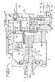
- FIG. 1illustrates a variable displacement type compressor, generally indicated in the drawings as reference 10 .
- the compressor 10includes a cylinder block 12 , a housing 14 that defines a crank chamber 16 , a drive shaft 18 , a swashplate 20 , a swashplate spring 22 , a rear housing 24 , at least one cylinder bore 26 , and at least one piston 28 .
- the rear housing 24defines a suction chamber 30 and a discharge chamber 32 .
- There is a valve plate 44that defines a suction port 34 and a discharge port 36 for each cylinder.
- the compressorcomprises a plurality of pistons and cylinders, for example, 5 pistons and cylinders, or 6 pistons and cylinders.
- the drive shaft 18is supported by the housing 14 such that a portion of the drive shaft 18 is disposed within the crank chamber 16 .
- the swashplate 20is mounted on the drive shaft 18 such that it is contained within the crank chamber 16 and is tilted away from a plane perpendicular to the longitudinal axis of the drive shaft 18 .
- the degree to which the swashplate 20 is tilted away from the plane perpendicular to the longitudinal axis of the drive shaft 18is indicated in the drawing as angle A.
- a spring 22acts upon swashplate 20 .
- the cylinder block 12defines the cylinder bore 26 .
- the piston 28is disposed within the cylinder bore 26 such that the piston 28 can slide in and out of the bore 26 .
- This slideable movement of the piston 28is possible, at least in part, due to the presence of a small clearance 38 between the interior surface 40 of the cylinder block 12 in the cylinder bore 26 and the exterior surface 42 of the piston 28 .
- the pistons 28may be secured to the swashplate 20 by shoes 54 , which allow for movement of the swashplate relative to the pistons.
- a solenoid valve 60comprising a stem 62 and two flow control elements 64 , 66 fixed on the stem.
- the valvedefines five chambers 68 , 70 , 72 , 74 , 76 for controlling the operation of the variable displacement compressor 10 .
- Passage 67communicates P c from chamber 74 to chamber 68 .
- chambers 68 and 74are thus at crankcase pressure, P c
- chamber 70is at the pressure of an oil separator, P os , which will be described below.
- Chamber 72is at discharge pressure, P d
- chamber 76is at the compressor suction pressure, P 1 .
- Orifice 77communicates between chambers 72 and 74 .
- a pressure of refrigerant gas returning from the evaporator, P evmay be used in place of P s .
- the solenoidhas a coil 78 which receives power from an external power source.
- the solenoid valvealso has springs 80 and 82 at opposite ends of the stem to balance the forces on the stem 62 .
- Spring 80is larger (having a greater spring constant) than spring 82 , so that when there is no current to the coil 78 , spring 80 urges the stem upward.
- valve 60depends primarily on the difference between discharge pressure P d and P s .
- the compressor systemmay also include a control system 95 , including a microprocessor-based controller 96 and memory 97 , and signal-conditioning circuitry 99 that controls the current to the solenoid coil 78 .
- the microprocessor-based controllermay include any useful controller, including PID or other types of controllers, and also desirably includes a pulse-width-modulation (PWM) routine for very quickly controlling the current to the solenoid.
- PWMpulse-width-modulation
- the controllermay have a number of inputs/outputs 98 , which may include a temperature indication from the passenger compartment and may also indicate a relative humidity from the passenger compartment.
- the controllermay control and also monitor the current to the solenoid by a current-reading device 94 , which may be internal or external to the controller.
- the solenoid currentis proportional to the load on the compressor and the air conditioning system.
- the control system 95may send an indication of the solenoid current or solenoid valve position to the vehicle powertrain control module for indicating the load on the compressor, and thus on the vehicle, caused by the air conditioning system.
- the pistonsWhen the swashplate is at its minimum angle, the pistons reciprocate to the least extent possible as the drive shaft rotates, compressing the smallest possible amount of refrigerant in the compressor, and using the least energy. When the swashplate is at its greatest angle, the pistons reciprocate up and down in their respective cylinders to the maximum extent, compressing much more refrigerant, and allowing the greatest air-conditioning effect. To achieve the greatest swashplate angle, the solenoid pulls the stem and flow control elements even further down in FIG. 1 , so that flow control element 64 closes communication between chamber 72 (P d ) and chamber 74 (P c ).
- control system 95 and microprocessor-based controller 96includes a pulse-width-modulation (PWM) routine for controlling the movement of solenoid valve 60 .
- PWM routinesa current is switched on and off, typically at a varying frequency, to achieve a desired control output by means of very fast switching between on and off. For instance, a square-wave pattern with short “off” periods may be used with longer and longer “on” periods to simulate a sinusoidal current.
- the valve stemis pulled downward, and the valve closes.
- spring 80overcomes the force of spring 82 , and the valve opens. This allows the valve to be very fast-acting and very responsive to the control signal, in this case, the difference between P d and P s .
- the compressorhas a number of passages to allow for communication of refrigerant pressure, and also for flow of refrigerant in, the compressor.
- Passage 46communicates crankcase pressure P c from the crankcase 16 to chamber 74 of the valve 60 .
- Passage 56communicates suction pressure (P s ) to chamber 76 of the valve.
- Passage 58communicates discharge pressure (P d ) from the discharge chamber to chamber 72 in valve 60 .
- passage 58may be a short passage from 1 to about 5 mm in diameter, preferably about 2-3 mm in diameter.
- chamber 68communicates with chamber 74 and receives crankcase pressure (P c ) through optional passageway or piping 67 .
- Orifice 77allows a flow of oil from chamber 72 at P d to chamber 74 at P c , and to the crankcase itself.
- passage 85may be a passage 85 from check valve 84 to crankcase 16
- additional passage 87from the crankcase 16 to the suction chamber 30 .
- Passage 85enables oil and refrigerant from the discharge to return to the crankcase.
- Passage 85is from about 1 mm to about 5 mm, preferably 2 mm to 3 mm.
- Passage 87allows flow between the crankcase and the suction. Passage 87 may be from 0.25 to 2 mm in diameter, preferably 0.8 mm.
- the passage itselfmay be long or may be as short as 2–4 mm.
- Refrigerant compressed by the compressorleaves the discharge chamber 32 via check valve 84 .
- Piping 86may convey the compressed refrigerant to an oil separator 88 , to prevent oil from entering the refrigeration system downstream of the oil separator 88 .
- Refrigerantleaves to a gas cooler or condenser (not shown) via plumbing 92 while oil is returned in oil return line 89 with flow control device 89 a .
- Flow control device 89 amay be an orifice or may be an electronic valve.
- the oil return linedesirably returns to the crankcase, where oil is needed to lubricate the working parts of the compressor, especially the pistons, cylinders, shoes and drive shaft.
- the check valvemay also have an oil return line 91 with flow control device 91 a to return oil to the crankcase.
- Either or both of the flow control devices 89 a and 91 amay be orifices or electronic valves, such as solenoid valves, that may be remotely opened or closed via controller 95 .
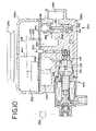
- FIG. 2depicts another embodiment of a variable displacement compressor 11 , which is similar to the embodiment of FIG. 1 .
- FIG. 2is depicted with somewhat different arrangements of plumbing, and is also shown in a state in which the swashplate 20 is at its minimum angle. In this view, the swashplate in now almost vertical, and piston 28 and shoes 54 have moved to the left, revealing more of cylinder bore 26 . In this position, there will be little compression of refrigerant, but all the working components within the crankcase chamber still require energy from the vehicle engine as the drive shaft continues to turn, and lubrication to prevent wear on all the moving parts. In the embodiment shown in FIG.
- the solenoid valve 60is shown in the closed position, with flow control element 66 preventing communication between chamber 76 (P s ) and chamber 74 (P c ), and flow control element 64 preventing communication between chamber 72 (P d ) and chamber 70 (P os ).
- Orifice 77allows a small pressure flow between P d and P c .
- control system 95may communicate this low load to the vehicle powertrain control module or to a vehicle controller.
- the refrigerantleaves the discharge chamber 32 and is directed first to an oil separator 88 and then to a check valve 105 before leaving via plumbing 107 to the downstream air conditioning components, such as a gas cooler.
- the oil separated by the oil separator 88may return via line 89 and flow control device 89 a to the crankcase chamber 16 .
- Flow control device 89 amay be an orifice or may be an electronic valve.
- Oilmay also return to the crankcase from the check valve 105 via return line 101 and flow control device 103 , which may be an orifice or may be an electronic valve, such as a solenoid valve.
- the pressure in the oil separatormay be communicated to the valve 69 via line 90 .
- FIGS. 3 and 4show details of the check valve 84 shown in FIG. 1 .
- This check valvechecks flow until the pressure, in this case discharge pressure, P d , reaches a certain level.
- the check valvemay be tailored by selection of spring 113 to allow flow only when the pressure has reached the desired level.
- the check valvemay be installed within the walls of rear chamber 24 .
- FIG. 3depicts the check valve closed, while FIG. 4 depicts the valve open, allowing refrigerant to flow via passage 86 .
- the valveis closed, with flow control element 111 , urged by spring 113 , preventing passage of refrigerant from the discharge chamber 32 through piping 86 .
- Orifice 115is desirably narrow, about 0.1 mm, but may range from about 0.1 mm to about 0.4 mm.
- FIG. 4depicts the check valve 84 in an open position, indicating that the discharge pressure of the refrigerant has reached a point sufficient to overcome the spring 113 , which is shown in a compressed state. Refrigerant can now freely pass through piping 86 .
- Check valve 84 or its flow control element 111may also use O-rings as shown, or other sealing devices as needed, such as piston rings.
- FIG. 5is a larger, cross-sectional view of a preferred embodiment of a solenoid valve 60 used in FIGS. 1 and 2 .
- the valveis a very fast acting solenoid valve, preferably controlled by a PWM routine using 400 Hz with the microprocessor-based controller 96 .
- the output of the controlleris current to solenoid coil 78 .
- the currentcauses stem 62 to move up or down, along with its flow control elements 64 and 66 .
- the stemis also urged in one direction by a larger spring 80 and in an opposite direction, by smaller spring 82 .
- spring 80 with a larger spring constantis able to overcome spring 82 with a smaller spring constant and close the valve.
- valveWithin the valve are five chambers, 68 , 70 , 72 , 74 and 76 .
- the chambersreceive pressures as discussed above, and are separated by valve head 69 and valve body internal walls 71 , 73 , 75 .
- the internal wallshave orifices as shown to allow passage of the stem 62 and also to allow pressure to communicate from one chamber to another.
- the valvehas orifices 90 a for receiving an oil separator pressure, 58 a for receiving a discharge pressure, 46 a for receiving a crankcase pressure, and 56 a for receiving a suction pressure.
- Valve head 69is movable within the valve, urged downward by spring 82 , upward by spring 80 , and upward or down by stem 62 .
- the valveis shown in the maximum open position, coil 78 at the maximum current, with flow control element 64 as far down as possible, allowing pressure to pass from chamber 70 (P os ) to chamber 72 (P d ) and preventing passage from chamber 72 (P d ) to chamber 74 (P c ).
- flow control element 66also at its lowest position, there is the greatest communication possible between chambers 74 (P c ) and 76 (P s ). In this position, there will be the greatest possible difference between the suction pressure and the discharge pressure. This will push the swashplate to its maximum angle, and the pistons will reciprocate to the maximum extent, thus compressing as much refrigerant as possible for the air conditioning system.
- FIG. 6depicts an alternate combination of the compressor and controls.
- Compressor 130 and control valve 132are connected as described above, with pressures from the compressor communicated to the valve by passages 137 , 139 and 141 , respectively from the compressor suction chamber 136 , crankcase chamber 134 , and discharge chamber 138 .
- Passage 137includes auxiliary passage 135 from the suction chamber.
- Valve 132comprises coil 140 , stem 142 and flow control elements 142 a and 142 b , as described above.
- Valve 132also comprises chambers 143 , 145 , 147 , 149 and 151 , the chambers separated by movable valve head 144 and valve body internal walls 146 , 148 , 150 .
- Tubing 67communicates P c from chamber 149 to chamber 143 .
- Passage 148 aallows for a small flow from chamber 149 at P c , to chamber 147 , at P d .
- Control system 195controls valve
- refrigerantleaves discharge chamber 138 via line 155 to check valve 152 .
- Check valve 152may also be equipped with a return line 154 to return oil to the crankcase 134 .
- Line 154may have a flow control device 153 to regulate the flow of return oil.
- Flow control device 153may be an orifice or may be an electronic control valve controlled by control system 195 .
- the refrigerantmay flow via line 157 to oil separator 158 and then to the refrigeration system via line 160 .
- line 160is preferably tubing about 5 mm in diameter, but tubing of other diameters may also be used, so long as too great a pressure drop is not induced in conveying the hot, compressed gas from the compressor to the other components of the vehicle refrigeration system.
- the oil separatormay have an oil return line 156 and flow control device 156 a to return oil to the compressor crankcase section 134 .
- Flow control device 156 amay be an orifice or may be an electronic control valve controlled by control system 195 .
- the flow control device 156 ais an orifice from about 0.1 mm to about 0.5 mm, preferably about 0.2 mm in diameter.
- P osmay be communicated to chamber 145 via tubing 159 with flow control device 159 a , which may be an orifice or may be an electronic control valve.
- oil return line 156is omitted and all oil from the oil separator 158 is returned via line 159 , preferably about 3 mm in diameter, to chamber 145 in valve 132 .
- the oil return line 154 from check valve 152is preferably about 3 mm in diameter; other diameter lines may be used.
- FIG. 7depicts another arrangement of lines for the compressor 130 , the oil separator 158 and the check valve 152 .
- the discharge chamber 138connects to the oil separator 158 via line 163 , the oil separator also having oil return line 167 with flow control device 167 a to return oil to crankcase chamber 134 .
- refrigerantflows to check valve 152 via line 161 , with an oil return line 165 to the oil separator.
- Refrigerantthen leaves the check valve on its way to the downstream air conditioning equipment.
- the compressor, check valve, and oil separator of FIG. 7as well as other configurations of a check valve, oil separator, and return line, may be used with three-way valves as well as four-way control valves.
- the above embodimentshave dealt mostly with four-way control valves.
- Other embodimentsmay use three-way control valves.
- Three way control valvesmay be used, for example, if the above-mentioned pressures, P d (discharge pressure), P c (crankcase pressure), and P s (supply pressure) are used to control the variable displacement of the compressor by controlling the angle of the swashplate or other controlling device, such as a wobbler plate.
- Three-way control valvesmay also be used if an auxiliary pressure is used to help control the pressures.
- An auxiliary pressure, P a that has been found usefulis one that results from a pressure drop from P d , the discharge pressure.
- P dis from about 5 to 20 bars (1 bar is 1 atmosphere of pressure), while P a is from about 0.1 to about 1 bar below that of P d .
- a pressure that has the requisite value for the auxiliary pressuremay be obtained by tapping the discharge pressure after it has gone through the control valve and associated piping, and has dropped by about 0.5 bar to about 1 bar.
- P dis from about 50 to 160 bars, while P a is from about 0.1 to about 10 bars less than that of P d .
- a pressure that has the requisite value for the auxiliary pressuremay be obtained by tapping the discharge pressure after it has gone through the control valve and associated piping and has dropped by about 0.1 bar to about 10 bars.
- Three-way control valve 200is similar in some respects to the four-way control valve described above, but is less complicated.
- Three-way control valve 200has a coil 201 , stem 202 with flow control elements 204 and 206 , a first strong spring 207 , second spring 209 , and an internal spring 208 .
- Valve body internal walls 215 , 217have orifices to allow passage of stem 202 and also pressures from chambers 214 , 216 , and 218 .
- Valve 200receives pressures from orifices 222 (P c ), 224 (P a ), and 226 (P d ).
- Internal spring 208may be used as an auxiliary spring in balancing the forces that move valve stem 202 in controlling the valve. Placed between fixed internal wall 215 and movable wall 213 , spring 208 may sometimes act to oppose the motion of stem 202 and sometimes act to reinforce the motion of stem 202 , depending on the force applied by coil 201 and springs 207 , 209 .
- tubingIn communicating pressures from the compressor to the control valve, tubing may be used, or channels internal to the compressor may be used to connect directly to the valve.
- discharge pressuremay connect from the discharge chamber of the compressor to chamber 216 via orifice 226 and tubing 225 .
- Tubing 225is desirably large enough to communicate P d without an appreciable drop in pressure.
- An auxiliary pressure P amay result if tubing 225 and orifice 224 , communicating between discharge pressure P d and chamber 214 , have diameters small enough to restrict flow and to induce a small pressure drop.
- Tubing having a diameter of preferably 3–4 mmis sufficient for this purpose. Other tubing having a diameter from about 1–5 mm may also be used.
- FIG. 8depicts the valve in maximum open position, with maximum current to coil 201 , and stem 202 and flow control elements 204 , 206 in their furthest upward positions, overcoming the force of strong spring 207 .
- Flow control element 204prevents flow between chambers 218 and 216
- flow control element 206allows maximum flow or pressure equalization between chambers 216 and 214 .
- this positionminimizes the difference between P a and P d , and prevents communication between P c and P d , thus allowing for maximum compressing of refrigerant in the compressor.
- FIG. 9depicts the same valve 200 , now in the off position. In this position, coil 201 receives the minimum or no current.
- Strong spring 207overcomes spring 209 , forcing stem 202 downward in FIG. 9 , and allowing communication between chambers 216 and 218 , but not between chambers 214 and 216 . This allows for the minimum possible compression, and tends to equalize the discharge and crankcase pressures, thus moving the swashplate to a position nearly perpendicular to the longitudinal axis of the drive shaft, and parallel or nearly parallel to a plane perpendicular to the longitudinal axis of the drive shaft.
- there may be a small passage between chambers 216 and 218from about 0.05 mm to about 0.6 mm.
- the passageis provided as either a passage 227 in chamber wall 217 (see FIG. 8 ) or a passage 205 in flow control element 205 ( FIG. 9 ). Passages 227 or 205 allow oil from the compressor discharge to return to the crankcase.
- the pressure difference across chamber wall 217is the discharge pressure P d minus the crankcase pressure, P c .
- P ddischarge pressure
- P acrankcase pressure
- P ccrankcase pressure
- the three-way control valvemay use the three chambers for P d , P c , and P d .
- Springsmay be designed with specific spring constants for the pressures and pressure ranges used. It will be appreciated that there are many other ways to use the three-way control valves depicted in FIGS. 8 and 9 . For instance, one alternate embodiment may use the three chambers, in order, for P s , P c and P d , with a single control element to regulate, as desired, the orifice between the chamber with P s and the chamber with P c , or the orifice between the chamber with P c and the chamber with P d .
- the source of the discharge pressuremay be the oil separator return line, with the oil return running through the valve, through the P c chamber, and returning oil to the crankcase.
- the chamber with P swas used for sensing only.
- An equivalentis to use a two-way valve, without a chamber for P s , and with appropriate compensation from springs or with appropriate input from the control system, in which the oil returns through the control valve.
- FIGS. 10 and 11are cross sectional views of a compressor 240 using a three-way control valve 200 .
- FIG. 10depicts compressor 240 with upper housing 248 a and lower housing 248 b , control valve 200 , and controller 290 , as described above in the description for controller 95 .
- the compressorhas a drive sheave 242 , drive shaft 244 , swash plate 246 , shown at a minimum angle to the drive shaft, and valve plate 250 , defining a crankcase chamber 252 , suction chamber 254 and discharge chamber 256 .
- the refrigerantAfter refrigerant leaves the discharge chamber and goes to the downstream refrigeration system (not shown), the refrigerant returns from the evaporator at a relatively low pressure, the pressure of the evaporator, to suction port 258 .
- flow from the suction port 258 to the suction chamber 254is governed by a suction shut-off valve 280 with upstream chamber 282 in compressor lower housing 248 b .
- Suction shut-off valve 280is shown in the closed position, preventing low-pressure refrigerant from passing from suction port 258 to suction chamber 254 .
- This passagemay be from about 0.05 to about 0.6 mm in diameter, preferably about 0.1 to about 0.15 mm.
- the valve 280may also have a spring 286 urging the valve closed and a second spring 287 on the opposite side urging the valve open.
- Spring 286preferably has a spring constant slightly higher than the spring constant of spring 287 , biasing the valve 280 closed.
- Line 268communicates P s to suction port 258 .
- Line 270communicates P a to upstream chamber 282 of shut-off valve 280 , thus controlling the position of valve 280 .
- Shut-off valve 280will thus be biased closed by spring 286 and P s , with spring 287 and P a opposed, tending to open valve 280 .
- valve 200is open, allowing pressure equalization between P d and P c , and tending to push the swashplate 246 to a minimum angle, and thus a minimum flow, in FIG. 10 .
- FIG. 11there is more demand for air conditioning, and movement of the internal components has occurred.
- the position of the valve 200is close to that depicted in FIG. 8 , with no communication between chambers 216 and 218 .
- the discharge pressureis not communicated to the crankcase, but rather is used fully for cooling.
- P dincreases, while P a decreases, overcoming the force of spring 286 .
- Shut-off valve 280 in FIG. 11moves upward, allowing communication between suction port 258 and suction chamber 254 .
- the swashplatewill move to a greater angle to the drive shaft of the compressor.
Landscapes
- Engineering & Computer Science (AREA)
- Mechanical Engineering (AREA)
- General Engineering & Computer Science (AREA)
- Compressors, Vaccum Pumps And Other Relevant Systems (AREA)
- Control Of Positive-Displacement Pumps (AREA)
Abstract
Description
Claims (17)
Priority Applications (4)
| Application Number | Priority Date | Filing Date | Title |
|---|---|---|---|
| US10/328,416US7014428B2 (en) | 2002-12-23 | 2002-12-23 | Controls for variable displacement compressor |
| GB0328199AGB2396669B (en) | 2002-12-23 | 2003-12-05 | Controls for variable displacement compressor |
| FR0314895AFR2849119A1 (en) | 2002-12-23 | 2003-12-18 | Variable displacement compressor for air conditioner in motor vehicle, has three-way control valve which is operated to change crankcase pressure and displacement of compressor |
| DE10361925ADE10361925B4 (en) | 2002-12-23 | 2003-12-22 | Controls for variable-speed compressors |
Applications Claiming Priority (1)
| Application Number | Priority Date | Filing Date | Title |
|---|---|---|---|
| US10/328,416US7014428B2 (en) | 2002-12-23 | 2002-12-23 | Controls for variable displacement compressor |
Publications (2)
| Publication Number | Publication Date |
|---|---|
| US20040120829A1 US20040120829A1 (en) | 2004-06-24 |
| US7014428B2true US7014428B2 (en) | 2006-03-21 |
Family
ID=29780459
Family Applications (1)
| Application Number | Title | Priority Date | Filing Date |
|---|---|---|---|
| US10/328,416Expired - LifetimeUS7014428B2 (en) | 2002-12-23 | 2002-12-23 | Controls for variable displacement compressor |
Country Status (4)
| Country | Link |
|---|---|
| US (1) | US7014428B2 (en) |
| DE (1) | DE10361925B4 (en) |
| FR (1) | FR2849119A1 (en) |
| GB (1) | GB2396669B (en) |
Cited By (13)
| Publication number | Priority date | Publication date | Assignee | Title |
|---|---|---|---|---|
| US20060228229A1 (en)* | 2005-04-06 | 2006-10-12 | Yoshinori Inoue | Piston type compressor |
| WO2008010798A1 (en)* | 2006-07-19 | 2008-01-24 | Carrier Corporation | Refrigerant system with pulse width modulation for reheat circuit |
| US20090022604A1 (en)* | 2007-07-18 | 2009-01-22 | Nobuaki Hoshino | Suction structure in piston type compressor |
| US20110001370A1 (en)* | 2008-03-03 | 2011-01-06 | Kabushiki Kaisha Kawasaki Precision Machinery | Electric motor integrated hydraulic motor |
| US8191537B1 (en)* | 2008-10-16 | 2012-06-05 | Cummings Filtration Ip, Inc. | Crankcase ventilation system with variable blower for increased efficiency |
| US20120234038A1 (en)* | 2009-12-02 | 2012-09-20 | Wolfgang Etter | Compressor |
| US20130259714A1 (en)* | 2010-12-14 | 2013-10-03 | Yukihiko Taguchi | Variable Displacement Compressor |
| US20150198257A1 (en)* | 2014-01-14 | 2015-07-16 | Halla Visteon Climate Control Corp. | Variable suction device for an a/c compressor to improve nvh by varying the suction inlet flow area |
| US20150240796A1 (en)* | 2014-02-27 | 2015-08-27 | Tgk Co., Ltd. | Control valve for variable displacement compressor |
| DE102017116184A1 (en) | 2016-07-21 | 2018-01-25 | Hanon Systems | Suction damping device with internal damping for a compressor of the air conditioning system of a vehicle |
| DE102018220709A1 (en) | 2017-12-05 | 2019-06-06 | Hanon Systems | Precise control of an intake damping device in a variable displacement compressor |
| US20220379773A1 (en)* | 2021-05-11 | 2022-12-01 | Hyundai Motor Company | Electric power and thermal management system |
| US11754087B2 (en) | 2021-05-11 | 2023-09-12 | Hyundai Motor Company | Oil dispersion system using actuator for propellers |
Families Citing this family (15)
| Publication number | Priority date | Publication date | Assignee | Title |
|---|---|---|---|---|
| US6976035B1 (en) | 1999-06-30 | 2005-12-13 | Siverbrook Research, Pty. Ltd | Method and system for navigating a history list |
| JP2006097665A (en)* | 2004-06-28 | 2006-04-13 | Toyota Industries Corp | Capacity control valve in variable displacement compressor |
| JP5181808B2 (en)* | 2008-04-28 | 2013-04-10 | 株式会社豊田自動織機 | Capacity control mechanism in variable capacity compressor |
| DE102011117354A1 (en)* | 2011-10-29 | 2013-05-02 | Volkswagen Aktiengesellschaft | Air conditioning compressor for a motor vehicle |
| JP6013767B2 (en)* | 2012-04-25 | 2016-10-25 | サンデンホールディングス株式会社 | Reciprocating compressor |
| US10066618B2 (en)* | 2014-11-05 | 2018-09-04 | Mahle International Gmbh | Variable displacement compressor with an oil check valve |
| JP2019094918A (en)* | 2017-11-17 | 2019-06-20 | サンデン・オートモーティブコンポーネント株式会社 | Displacement control valve of variable displacement compressor |
| KR102547593B1 (en) | 2018-07-19 | 2023-06-27 | 한온시스템 주식회사 | Variable displacement swash plate type compressor |
| KR102603184B1 (en) | 2018-12-04 | 2023-11-16 | 이구루코교 가부시기가이샤 | capacity control valve |
| CN114051559B (en)* | 2019-07-11 | 2023-01-31 | 伊格尔工业股份有限公司 | capacity control valve |
| JP7383362B2 (en)* | 2019-07-12 | 2023-11-20 | イーグル工業株式会社 | capacity control valve |
| US12129840B2 (en) | 2019-10-28 | 2024-10-29 | Eagle Industry Co., Ltd. | Capacity control valve |
| WO2021167301A1 (en)* | 2020-02-19 | 2021-08-26 | 한온시스템 주식회사 | Swash plate-type compressor control method and swash plate-type compressor |
| US12025237B2 (en) | 2020-05-25 | 2024-07-02 | Eagle Industry Co., Ltd. | Capacity control valve |
| WO2021241478A1 (en) | 2020-05-25 | 2021-12-02 | イーグル工業株式会社 | Capacity control valve |
Citations (40)
| Publication number | Priority date | Publication date | Assignee | Title |
|---|---|---|---|---|
| US3772888A (en) | 1972-07-27 | 1973-11-20 | Lamb Co F Jos | Hydrostatic transfer drive |
| US3977424A (en) | 1975-04-14 | 1976-08-31 | Clark Equipment Company | Differential pressure regulator valve for a hydrostatic transmission control system |
| JPS5977086A (en) | 1982-10-22 | 1984-05-02 | Mitsubishi Heavy Ind Ltd | Swash-plate type axial piston pump and motor |
| US5027612A (en) | 1987-09-22 | 1991-07-02 | Sanden Corporation | Refrigerating system having a compressor with an internally and externally controlled variable displacement mechanism |
| US5577894A (en) | 1993-11-05 | 1996-11-26 | Kabushiki Kaisha Toyoda Jidoshokki Seisakusho | Piston type variable displacement compressor |
| EP0798461A2 (en) | 1996-03-29 | 1997-10-01 | Sanden Corporation | Refrigerant circuit with fluid flow control mechanism |
| EP0881387A2 (en) | 1997-05-26 | 1998-12-02 | Zexel Corporation | Clutchless variable capacity swash plate compressor |
| US5893706A (en) | 1995-04-07 | 1999-04-13 | Kabushiki Kaisha Toyoda Jidoshokki Seisakusho | Cooling structure for compressor |
| WO1999025977A1 (en) | 1997-11-13 | 1999-05-27 | Zexel Corporation | Variable displacement swash plate type clutchless compressor |
| EP0926341A2 (en) | 1997-12-24 | 1999-06-30 | Kabushiki Kaisha Toyoda Jidoshokki Seisakusho | Oil recovery device for compressors |
| EP0926346A2 (en) | 1997-12-24 | 1999-06-30 | Kabushiki Kaisha Toyoda Jidoshokki Seisakusho | Compressor |
| EP0935107A2 (en) | 1998-02-06 | 1999-08-11 | Kabushiki Kaisha Toyoda Jidoshokki Seisakusho | Method and apparatus for controlling variable displacement compressor |
| EP0940581A2 (en) | 1998-03-06 | 1999-09-08 | Kabushiki Kaisha Toyoda Jidoshokki Seisakusho | Pressure pulsation muffler for the discharge valve of a compressor |
| US5997257A (en) | 1997-01-28 | 1999-12-07 | Zexel Corporation | Refrigerant compressor |
| WO1999066203A1 (en) | 1998-06-16 | 1999-12-23 | Bosch Automotive Systems Corporation | Variable displacement swash plate type clutchless compressor |
| US6010314A (en)* | 1997-01-10 | 2000-01-04 | Kabushiki Kaisha Toyoda Jidoshokki Seisakusho | Swash-plate compressor having a capacity control valve on the oil return passageway adjacent an oil separator |
| JP2000009044A (en) | 1997-12-26 | 2000-01-11 | Toyota Autom Loom Works Ltd | Capacity control valve in variable displacement compressor |
| US6015269A (en)* | 1996-12-10 | 2000-01-18 | Kabushiki Kaisha Toyoda Jidoshokki Seisakusho | Variable displacement compressor |
| EP1020641A2 (en) | 1999-01-18 | 2000-07-19 | Kabushiki Kaisha Toyoda Jidoshokki Seisakusho | Variable capacity type compressor with inclined capacity control valve |
| EP1034951A2 (en) | 1999-03-10 | 2000-09-13 | Seiko Seiki Kabushiki Kaisha | Idling engine speed control apparatus |
| US6149398A (en)* | 1998-03-16 | 2000-11-21 | Kabushiki Kaisha Toyoda Jidoshokki Seisakusho | Variable capacity piston- operated refrigerant compressor with an oil separating means |
| EP1059444A2 (en) | 1999-06-07 | 2000-12-13 | Kabushiki Kaisha Toyoda Jidoshokki Seisakusho | Variable capacity compressor with check valve with damper |
| EP1059446A2 (en) | 1999-06-07 | 2000-12-13 | Kabushiki Kaisha Toyoda Jidoshokki Seisakusho | Variable capacity type compressor with check valve |
| EP1059445A2 (en) | 1999-06-07 | 2000-12-13 | Kabushiki Kaisha Toyoda Jidoshokki Seisakusho | Variable capacity type compressor with check valve |
| US6179578B1 (en) | 1998-06-15 | 2001-01-30 | Kabushiki Kaisha Toyoda Jidishokki Seisakusho | Compressor with oil separating structure |
| US6227812B1 (en) | 1997-03-13 | 2001-05-08 | Kabushiki Kaisha Toyoda Jidoshokki Seisakusho | Refrigerant circuit and compressor |
| EP1099852A2 (en) | 1999-11-10 | 2001-05-16 | Kabushiki Kaisha Toyoda Jidoshokki Seisakusho | Control valve for variable displacement compressors |
| US6234763B1 (en) | 1998-11-27 | 2001-05-22 | Kabushiki Kaisha Toyoda Jidoshokki Seisakusho | Variable displacement compressor |
| WO2001053699A1 (en) | 2000-01-21 | 2001-07-26 | Zexel Valeo Climate Control Corporation | Variable-displacement swash plate type clutchless compressor |
| EP1126169A2 (en) | 2000-02-18 | 2001-08-22 | Calsonic Kansei Corporation | Swashplate type variable-displacement compressor |
| EP1138946A2 (en) | 2000-03-30 | 2001-10-04 | Kabushiki Kaisha Toyoda Jidoshokki Seisakusho | Control valve for variable displacement compressor |
| EP1138932A2 (en) | 2000-03-31 | 2001-10-04 | Honda Giken Kogyo Kabushiki Kaisha | An air cleaner fitting structure for a motorcycle |
| EP1167762A2 (en) | 2000-06-27 | 2002-01-02 | Kabushiki Kaisha Toyota Jidoshokki | Lubrication system for swash plate compressor |
| US20020015645A1 (en)* | 2000-07-14 | 2002-02-07 | Takeshi Yamada | Compressor |
| US20020025258A1 (en)* | 2000-04-07 | 2002-02-28 | Masaki Ota | Variable displacement compressors |
| US6352416B1 (en) | 1999-03-15 | 2002-03-05 | Kabushiki Kaisha Toyoda Jidoshokki Seisakusho | Device and method for controlling displacement of variable displacement compressor |
| EP1207301A2 (en) | 2000-11-17 | 2002-05-22 | Kabushiki Kaisha Toyota Jidoshokki | Variable displacement compressor |
| US6431053B1 (en) | 2001-03-08 | 2002-08-13 | Visteon Global Technologies, Inc. | Piston for a swashplate reciprocating compressor |
| US6508634B2 (en)* | 2000-07-17 | 2003-01-21 | Kabushiki Kaisha Toyoda Jidoshokki Seisakusho | Compressor utilizing spaces between cylinder bores |
| EP1363023A2 (en) | 2002-05-13 | 2003-11-19 | TGK CO., Ltd. | Capacity control valve for variable displacement compressor |
- 2002
- 2002-12-23USUS10/328,416patent/US7014428B2/ennot_activeExpired - Lifetime
- 2003
- 2003-12-05GBGB0328199Apatent/GB2396669B/ennot_activeExpired - Lifetime
- 2003-12-18FRFR0314895Apatent/FR2849119A1/ennot_activeWithdrawn
- 2003-12-22DEDE10361925Apatent/DE10361925B4/ennot_activeExpired - Fee Related
Patent Citations (56)
| Publication number | Priority date | Publication date | Assignee | Title |
|---|---|---|---|---|
| US3772888A (en) | 1972-07-27 | 1973-11-20 | Lamb Co F Jos | Hydrostatic transfer drive |
| US3977424A (en) | 1975-04-14 | 1976-08-31 | Clark Equipment Company | Differential pressure regulator valve for a hydrostatic transmission control system |
| JPS5977086A (en) | 1982-10-22 | 1984-05-02 | Mitsubishi Heavy Ind Ltd | Swash-plate type axial piston pump and motor |
| US5027612A (en) | 1987-09-22 | 1991-07-02 | Sanden Corporation | Refrigerating system having a compressor with an internally and externally controlled variable displacement mechanism |
| US5577894A (en) | 1993-11-05 | 1996-11-26 | Kabushiki Kaisha Toyoda Jidoshokki Seisakusho | Piston type variable displacement compressor |
| US5893706A (en) | 1995-04-07 | 1999-04-13 | Kabushiki Kaisha Toyoda Jidoshokki Seisakusho | Cooling structure for compressor |
| EP0798461A2 (en) | 1996-03-29 | 1997-10-01 | Sanden Corporation | Refrigerant circuit with fluid flow control mechanism |
| EP0798461A3 (en) | 1996-03-29 | 1998-10-21 | Sanden Corporation | Refrigerant circuit with fluid flow control mechanism |
| US6015269A (en)* | 1996-12-10 | 2000-01-18 | Kabushiki Kaisha Toyoda Jidoshokki Seisakusho | Variable displacement compressor |
| US6010314A (en)* | 1997-01-10 | 2000-01-04 | Kabushiki Kaisha Toyoda Jidoshokki Seisakusho | Swash-plate compressor having a capacity control valve on the oil return passageway adjacent an oil separator |
| US5997257A (en) | 1997-01-28 | 1999-12-07 | Zexel Corporation | Refrigerant compressor |
| US6227812B1 (en) | 1997-03-13 | 2001-05-08 | Kabushiki Kaisha Toyoda Jidoshokki Seisakusho | Refrigerant circuit and compressor |
| EP0881387A2 (en) | 1997-05-26 | 1998-12-02 | Zexel Corporation | Clutchless variable capacity swash plate compressor |
| US6045337A (en) | 1997-05-26 | 2000-04-04 | Zexel Corporation | Clutchless variable capacity swash plate compressor |
| WO1999025977A1 (en) | 1997-11-13 | 1999-05-27 | Zexel Corporation | Variable displacement swash plate type clutchless compressor |
| US6206648B1 (en)* | 1997-12-24 | 2001-03-27 | Kabushiki Kaisha Toyoda Jidoshokki Seisakusho | Compressor |
| EP0926346A3 (en) | 1997-12-24 | 2001-04-11 | Kabushiki Kaisha Toyoda Jidoshokki Seisakusho | Compressor |
| EP0926346A2 (en) | 1997-12-24 | 1999-06-30 | Kabushiki Kaisha Toyoda Jidoshokki Seisakusho | Compressor |
| EP0926341A2 (en) | 1997-12-24 | 1999-06-30 | Kabushiki Kaisha Toyoda Jidoshokki Seisakusho | Oil recovery device for compressors |
| JP2000009044A (en) | 1997-12-26 | 2000-01-11 | Toyota Autom Loom Works Ltd | Capacity control valve in variable displacement compressor |
| US6164925A (en) | 1997-12-26 | 2000-12-26 | Kabushiki Kaisha Toyoda Jidoshokki Seisakusho | Control valve for variable displacement compressors |
| EP0935107A3 (en) | 1998-02-06 | 2002-01-16 | Kabushiki Kaisha Toyota Jidoshokki | Method and apparatus for controlling variable displacement compressor |
| EP0935107A2 (en) | 1998-02-06 | 1999-08-11 | Kabushiki Kaisha Toyoda Jidoshokki Seisakusho | Method and apparatus for controlling variable displacement compressor |
| EP0940581A3 (en) | 1998-03-06 | 2000-04-26 | Kabushiki Kaisha Toyoda Jidoshokki Seisakusho | Pressure pulsation muffler for the discharge valve of a compressor |
| US6149397A (en) | 1998-03-06 | 2000-11-21 | Toyoda Automatic Loom Works, Ltd. | Pressure pulsations reducing compressor |
| EP0940581A2 (en) | 1998-03-06 | 1999-09-08 | Kabushiki Kaisha Toyoda Jidoshokki Seisakusho | Pressure pulsation muffler for the discharge valve of a compressor |
| US6149398A (en)* | 1998-03-16 | 2000-11-21 | Kabushiki Kaisha Toyoda Jidoshokki Seisakusho | Variable capacity piston- operated refrigerant compressor with an oil separating means |
| US6179578B1 (en) | 1998-06-15 | 2001-01-30 | Kabushiki Kaisha Toyoda Jidishokki Seisakusho | Compressor with oil separating structure |
| WO1999066203A1 (en) | 1998-06-16 | 1999-12-23 | Bosch Automotive Systems Corporation | Variable displacement swash plate type clutchless compressor |
| US6234763B1 (en) | 1998-11-27 | 2001-05-22 | Kabushiki Kaisha Toyoda Jidoshokki Seisakusho | Variable displacement compressor |
| EP1020641A3 (en) | 1999-01-18 | 2000-12-27 | Kabushiki Kaisha Toyoda Jidoshokki Seisakusho | Variable capacity type compressor with inclined capacity control valve |
| EP1020641A2 (en) | 1999-01-18 | 2000-07-19 | Kabushiki Kaisha Toyoda Jidoshokki Seisakusho | Variable capacity type compressor with inclined capacity control valve |
| EP1034951A2 (en) | 1999-03-10 | 2000-09-13 | Seiko Seiki Kabushiki Kaisha | Idling engine speed control apparatus |
| EP1034951A3 (en) | 1999-03-10 | 2002-01-30 | Seiko Seiki Kabushiki Kaisha | Idling engine speed control apparatus |
| US6352416B1 (en) | 1999-03-15 | 2002-03-05 | Kabushiki Kaisha Toyoda Jidoshokki Seisakusho | Device and method for controlling displacement of variable displacement compressor |
| EP1059444A3 (en) | 1999-06-07 | 2002-06-26 | Kabushiki Kaisha Toyota Jidoshokki | Variable capacity compressor with check valve with damper |
| EP1059445A2 (en) | 1999-06-07 | 2000-12-13 | Kabushiki Kaisha Toyoda Jidoshokki Seisakusho | Variable capacity type compressor with check valve |
| EP1059446A3 (en) | 1999-06-07 | 2002-06-26 | Kabushiki Kaisha Toyota Jidoshokki | Variable capacity type compressor with check valve |
| EP1059444A2 (en) | 1999-06-07 | 2000-12-13 | Kabushiki Kaisha Toyoda Jidoshokki Seisakusho | Variable capacity compressor with check valve with damper |
| EP1059446A2 (en) | 1999-06-07 | 2000-12-13 | Kabushiki Kaisha Toyoda Jidoshokki Seisakusho | Variable capacity type compressor with check valve |
| EP1059445A3 (en) | 1999-06-07 | 2002-06-19 | Kabushiki Kaisha Toyota Jidoshokki | Variable capacity type compressor with check valve |
| EP1099852A3 (en) | 1999-11-10 | 2003-08-20 | Kabushiki Kaisha Toyota Jidoshokki | Control valve for variable displacement compressors |
| EP1099852A2 (en) | 1999-11-10 | 2001-05-16 | Kabushiki Kaisha Toyoda Jidoshokki Seisakusho | Control valve for variable displacement compressors |
| WO2001053699A1 (en) | 2000-01-21 | 2001-07-26 | Zexel Valeo Climate Control Corporation | Variable-displacement swash plate type clutchless compressor |
| EP1126169A2 (en) | 2000-02-18 | 2001-08-22 | Calsonic Kansei Corporation | Swashplate type variable-displacement compressor |
| EP1138946A2 (en) | 2000-03-30 | 2001-10-04 | Kabushiki Kaisha Toyoda Jidoshokki Seisakusho | Control valve for variable displacement compressor |
| EP1138932A2 (en) | 2000-03-31 | 2001-10-04 | Honda Giken Kogyo Kabushiki Kaisha | An air cleaner fitting structure for a motorcycle |
| US20020025258A1 (en)* | 2000-04-07 | 2002-02-28 | Masaki Ota | Variable displacement compressors |
| EP1167762A2 (en) | 2000-06-27 | 2002-01-02 | Kabushiki Kaisha Toyota Jidoshokki | Lubrication system for swash plate compressor |
| EP1167762A3 (en) | 2000-06-27 | 2003-07-23 | Kabushiki Kaisha Toyota Jidoshokki | Lubrication system for swash plate compressor |
| US20020015645A1 (en)* | 2000-07-14 | 2002-02-07 | Takeshi Yamada | Compressor |
| US6508634B2 (en)* | 2000-07-17 | 2003-01-21 | Kabushiki Kaisha Toyoda Jidoshokki Seisakusho | Compressor utilizing spaces between cylinder bores |
| EP1207301A2 (en) | 2000-11-17 | 2002-05-22 | Kabushiki Kaisha Toyota Jidoshokki | Variable displacement compressor |
| EP1207301A3 (en) | 2000-11-17 | 2003-09-17 | Kabushiki Kaisha Toyota Jidoshokki | Variable displacement compressor |
| US6431053B1 (en) | 2001-03-08 | 2002-08-13 | Visteon Global Technologies, Inc. | Piston for a swashplate reciprocating compressor |
| EP1363023A2 (en) | 2002-05-13 | 2003-11-19 | TGK CO., Ltd. | Capacity control valve for variable displacement compressor |
Non-Patent Citations (2)
| Title |
|---|
| Combined Search and Examination Report dated Apr. 19, 2004, for corresponding United Kingdom application GB 0328199.5. |
| Search report for corresponding GB application, GB0328199.5, dated Oct. 8, 2004. |
Cited By (27)
| Publication number | Priority date | Publication date | Assignee | Title |
|---|---|---|---|---|
| US20060228229A1 (en)* | 2005-04-06 | 2006-10-12 | Yoshinori Inoue | Piston type compressor |
| WO2008010798A1 (en)* | 2006-07-19 | 2008-01-24 | Carrier Corporation | Refrigerant system with pulse width modulation for reheat circuit |
| US20100064722A1 (en)* | 2006-07-19 | 2010-03-18 | Taras Michael F | Refrigerant system with pulse width modulation for reheat circuit |
| CN101512266B (en)* | 2006-07-19 | 2013-01-02 | 开利公司 | Refrigeration system with pulse width modulation for reheat circuit |
| US20090022604A1 (en)* | 2007-07-18 | 2009-01-22 | Nobuaki Hoshino | Suction structure in piston type compressor |
| US20110001370A1 (en)* | 2008-03-03 | 2011-01-06 | Kabushiki Kaisha Kawasaki Precision Machinery | Electric motor integrated hydraulic motor |
| US8358042B2 (en)* | 2008-03-03 | 2013-01-22 | Kawasaki Jukogyo Kabushiki Kaisha | Electric motor integrated hydraulic motor |
| US8191537B1 (en)* | 2008-10-16 | 2012-06-05 | Cummings Filtration Ip, Inc. | Crankcase ventilation system with variable blower for increased efficiency |
| US20120234038A1 (en)* | 2009-12-02 | 2012-09-20 | Wolfgang Etter | Compressor |
| US9021830B2 (en)* | 2009-12-02 | 2015-05-05 | Gea Bock Gmbh | Compressor |
| US20130259714A1 (en)* | 2010-12-14 | 2013-10-03 | Yukihiko Taguchi | Variable Displacement Compressor |
| DE102015100380A1 (en) | 2014-01-14 | 2015-07-16 | Halla Visteon Climate Control Corp. | Variable suction device for an A / C compressor to improve the NVH properties by changing the suction inlet flow area |
| US20150198257A1 (en)* | 2014-01-14 | 2015-07-16 | Halla Visteon Climate Control Corp. | Variable suction device for an a/c compressor to improve nvh by varying the suction inlet flow area |
| US9488289B2 (en)* | 2014-01-14 | 2016-11-08 | Hanon Systems | Variable suction device for an A/C compressor to improve nvh by varying the suction inlet flow area |
| DE102015100380B4 (en)* | 2014-01-14 | 2019-08-29 | Halla Visteon Climate Control Corp. | Variable suction device for an A / C compressor to improve the NVH properties by changing the suction inlet flow area |
| US20150240796A1 (en)* | 2014-02-27 | 2015-08-27 | Tgk Co., Ltd. | Control valve for variable displacement compressor |
| US20150260176A1 (en)* | 2014-02-27 | 2015-09-17 | Tgk Co., Ltd. | Control valve for variable displacement compressor |
| US9512833B2 (en)* | 2014-02-27 | 2016-12-06 | Tgk Co., Ltd. | Control valve for variable displacement compressor |
| DE102017116184B4 (en) | 2016-07-21 | 2018-11-22 | Hanon Systems | Suction damping device with internal damping for a compressor of the air conditioning system of a vehicle |
| DE102017116184A1 (en) | 2016-07-21 | 2018-01-25 | Hanon Systems | Suction damping device with internal damping for a compressor of the air conditioning system of a vehicle |
| DE102018220709A1 (en) | 2017-12-05 | 2019-06-06 | Hanon Systems | Precise control of an intake damping device in a variable displacement compressor |
| US10655617B2 (en) | 2017-12-05 | 2020-05-19 | Hanon Systems | Precise control of suction damping device in a variable displacement compressor |
| DE102018220709B4 (en)* | 2017-12-05 | 2021-06-02 | Hanon Systems | Precise control of an intake damper in a variable displacement compressor |
| US11319939B2 (en)* | 2017-12-05 | 2022-05-03 | Hanon Systems | Precise control of suction damping device in a variable displacement compressor |
| US20220379773A1 (en)* | 2021-05-11 | 2022-12-01 | Hyundai Motor Company | Electric power and thermal management system |
| US11754087B2 (en) | 2021-05-11 | 2023-09-12 | Hyundai Motor Company | Oil dispersion system using actuator for propellers |
| US11760228B2 (en)* | 2021-05-11 | 2023-09-19 | Hyundai Motor Company | Electric power and thermal management system |
Also Published As
| Publication number | Publication date |
|---|---|
| FR2849119A1 (en) | 2004-06-25 |
| DE10361925B4 (en) | 2007-12-06 |
| US20040120829A1 (en) | 2004-06-24 |
| GB2396669B (en) | 2006-02-01 |
| GB0328199D0 (en) | 2004-01-07 |
| GB2396669A (en) | 2004-06-30 |
| DE10361925A1 (en) | 2004-07-08 |
Similar Documents
| Publication | Publication Date | Title |
|---|---|---|
| US7014428B2 (en) | Controls for variable displacement compressor | |
| CN1077235C (en) | Displacement controlling structure for clutchless variable displacement compressor | |
| US4606705A (en) | Variable displacement compressor control valve arrangement | |
| US5653119A (en) | Refrigerating system incorporating therein a variable capacity refrigerant compressor | |
| US6358017B1 (en) | Control valve for variable displacement compressor | |
| US5871337A (en) | Swash-plate compressor with leakage passages through the discharge valves of the cylinders | |
| US6227812B1 (en) | Refrigerant circuit and compressor | |
| US6062823A (en) | Control valve in variable displacement compressor | |
| US5890876A (en) | Control valve in variable displacement compressor | |
| US20070214814A1 (en) | Displacement control valve of variable displacement compressor | |
| JPS62674A (en) | Capacity controller for variable angle swing swash type variable capacity compressor | |
| US20010027659A1 (en) | Control apparatus and control method for variable displacement compressor | |
| US5681150A (en) | Piston type variable displacement compressor | |
| EP1489304A1 (en) | Displacement control mechanism of a variable displacement type compressor | |
| US6863503B2 (en) | Variable capacity compressor | |
| US6443707B1 (en) | Control valve for variable displacement compressor | |
| US6672844B2 (en) | Apparatus and method for controlling variable displacement compressor | |
| US6217291B1 (en) | Control valve for variable displacement compressors and method for varying displacement | |
| US20020104327A1 (en) | Vehicular air conditioner | |
| EP1363021A1 (en) | Compression displacement controller of refrigerating cycle | |
| US6729853B2 (en) | Displacement control device for variable displacement compressor | |
| US6783332B2 (en) | Control valve of variable displacement compressor with pressure sensing member | |
| US20020144512A1 (en) | Apparatus and method for controlling variable displacement compressor | |
| US5240385A (en) | Variable displacement wobble plate type compressor | |
| US6776585B2 (en) | Control valve for a wobbleplate compressor |
Legal Events
| Date | Code | Title | Description |
|---|---|---|---|
| AS | Assignment | Owner name:VISTEON GLOBAL TECHNOLOGIES, INC., MICHIGAN Free format text:ASSIGNMENT OF ASSIGNORS INTEREST;ASSIGNORS:PITLA, SRINIVAS S.;HUANG, YONG;KHETARPAL, VIPEN;REEL/FRAME:013877/0495 Effective date:20030307 | |
| STCF | Information on status: patent grant | Free format text:PATENTED CASE | |
| AS | Assignment | Owner name:JPMORGAN CHASE BANK, N.A., AS ADMINISTRATIVE AGENT Free format text:SECURITY AGREEMENT;ASSIGNOR:VISTEON GLOBAL TECHNOLOGIES, INC.;REEL/FRAME:020497/0733 Effective date:20060613 | |
| AS | Assignment | Owner name:JPMORGAN CHASE BANK, TEXAS Free format text:SECURITY INTEREST;ASSIGNOR:VISTEON GLOBAL TECHNOLOGIES, INC.;REEL/FRAME:022368/0001 Effective date:20060814 Owner name:JPMORGAN CHASE BANK,TEXAS Free format text:SECURITY INTEREST;ASSIGNOR:VISTEON GLOBAL TECHNOLOGIES, INC.;REEL/FRAME:022368/0001 Effective date:20060814 | |
| AS | Assignment | Owner name:WILMINGTON TRUST FSB, AS ADMINISTRATIVE AGENT, MIN Free format text:ASSIGNMENT OF SECURITY INTEREST IN PATENTS;ASSIGNOR:JPMORGAN CHASE BANK, N.A., AS ADMINISTRATIVE AGENT;REEL/FRAME:022575/0186 Effective date:20090415 Owner name:WILMINGTON TRUST FSB, AS ADMINISTRATIVE AGENT,MINN Free format text:ASSIGNMENT OF SECURITY INTEREST IN PATENTS;ASSIGNOR:JPMORGAN CHASE BANK, N.A., AS ADMINISTRATIVE AGENT;REEL/FRAME:022575/0186 Effective date:20090415 | |
| FPAY | Fee payment | Year of fee payment:4 | |
| AS | Assignment | Owner name:THE BANK OF NEW YORK MELLON, AS ADMINISTRATIVE AGE Free format text:ASSIGNMENT OF PATENT SECURITY INTEREST;ASSIGNOR:JPMORGAN CHASE BANK, N.A., A NATIONAL BANKING ASSOCIATION;REEL/FRAME:022974/0057 Effective date:20090715 | |
| AS | Assignment | Owner name:VISTEON GLOBAL TECHNOLOGIES, INC., MICHIGAN Free format text:RELEASE BY SECURED PARTY AGAINST SECURITY INTEREST IN PATENTS RECORDED AT REEL 022974 FRAME 0057;ASSIGNOR:THE BANK OF NEW YORK MELLON;REEL/FRAME:025095/0711 Effective date:20101001 | |
| AS | Assignment | Owner name:VISTEON GLOBAL TECHNOLOGIES, INC., MICHIGAN Free format text:RELEASE BY SECURED PARTY AGAINST SECURITY INTEREST IN PATENTS RECORDED AT REEL 022575 FRAME 0186;ASSIGNOR:WILMINGTON TRUST FSB, AS ADMINISTRATIVE AGENT;REEL/FRAME:025105/0201 Effective date:20101001 | |
| AS | Assignment | Owner name:MORGAN STANLEY SENIOR FUNDING, INC., AS AGENT, NEW Free format text:SECURITY AGREEMENT;ASSIGNORS:VISTEON CORPORATION;VC AVIATION SERVICES, LLC;VISTEON ELECTRONICS CORPORATION;AND OTHERS;REEL/FRAME:025241/0317 Effective date:20101007 Owner name:MORGAN STANLEY SENIOR FUNDING, INC., AS AGENT, NEW Free format text:SECURITY AGREEMENT (REVOLVER);ASSIGNORS:VISTEON CORPORATION;VC AVIATION SERVICES, LLC;VISTEON ELECTRONICS CORPORATION;AND OTHERS;REEL/FRAME:025238/0298 Effective date:20101001 | |
| AS | Assignment | Owner name:VISTEON INTERNATIONAL HOLDINGS, INC., MICHIGAN Free format text:RELEASE BY SECURED PARTY AGAINST SECURITY INTEREST IN PATENTS ON REEL 025241 FRAME 0317;ASSIGNOR:MORGAN STANLEY SENIOR FUNDING, INC.;REEL/FRAME:026178/0412 Effective date:20110406 Owner name:VC AVIATION SERVICES, LLC, MICHIGAN Free format text:RELEASE BY SECURED PARTY AGAINST SECURITY INTEREST IN PATENTS ON REEL 025241 FRAME 0317;ASSIGNOR:MORGAN STANLEY SENIOR FUNDING, INC.;REEL/FRAME:026178/0412 Effective date:20110406 Owner name:VISTEON CORPORATION, MICHIGAN Free format text:RELEASE BY SECURED PARTY AGAINST SECURITY INTEREST IN PATENTS ON REEL 025241 FRAME 0317;ASSIGNOR:MORGAN STANLEY SENIOR FUNDING, INC.;REEL/FRAME:026178/0412 Effective date:20110406 Owner name:VISTEON EUROPEAN HOLDING, INC., MICHIGAN Free format text:RELEASE BY SECURED PARTY AGAINST SECURITY INTEREST IN PATENTS ON REEL 025241 FRAME 0317;ASSIGNOR:MORGAN STANLEY SENIOR FUNDING, INC.;REEL/FRAME:026178/0412 Effective date:20110406 Owner name:VISTEON GLOBAL TECHNOLOGIES, INC., MICHIGAN Free format text:RELEASE BY SECURED PARTY AGAINST SECURITY INTEREST IN PATENTS ON REEL 025241 FRAME 0317;ASSIGNOR:MORGAN STANLEY SENIOR FUNDING, INC.;REEL/FRAME:026178/0412 Effective date:20110406 Owner name:VISTEON INTERNATIONAL BUSINESS DEVELOPMENT, INC., Free format text:RELEASE BY SECURED PARTY AGAINST SECURITY INTEREST IN PATENTS ON REEL 025241 FRAME 0317;ASSIGNOR:MORGAN STANLEY SENIOR FUNDING, INC.;REEL/FRAME:026178/0412 Effective date:20110406 Owner name:VISTEON ELECTRONICS CORPORATION, MICHIGAN Free format text:RELEASE BY SECURED PARTY AGAINST SECURITY INTEREST IN PATENTS ON REEL 025241 FRAME 0317;ASSIGNOR:MORGAN STANLEY SENIOR FUNDING, INC.;REEL/FRAME:026178/0412 Effective date:20110406 Owner name:VISTEON GLOBAL TREASURY, INC., MICHIGAN Free format text:RELEASE BY SECURED PARTY AGAINST SECURITY INTEREST IN PATENTS ON REEL 025241 FRAME 0317;ASSIGNOR:MORGAN STANLEY SENIOR FUNDING, INC.;REEL/FRAME:026178/0412 Effective date:20110406 Owner name:VISTEON SYSTEMS, LLC, MICHIGAN Free format text:RELEASE BY SECURED PARTY AGAINST SECURITY INTEREST IN PATENTS ON REEL 025241 FRAME 0317;ASSIGNOR:MORGAN STANLEY SENIOR FUNDING, INC.;REEL/FRAME:026178/0412 Effective date:20110406 | |
| AS | Assignment | Owner name:HALLA VISTEON CLIMATE CONTROL CORPORATION, KOREA, Free format text:ASSIGNMENT OF ASSIGNORS INTEREST;ASSIGNOR:VISTEON GLOBAL TECHNOLOGIES, INC.;REEL/FRAME:030935/0969 Effective date:20130726 | |
| FPAY | Fee payment | Year of fee payment:8 | |
| AS | Assignment | Owner name:VISTEON EUROPEAN HOLDINGS, INC., MICHIGAN Free format text:RELEASE OF SECURITY INTEREST IN INTELLECTUAL PROPERTY;ASSIGNOR:MORGAN STANLEY SENIOR FUNDING, INC.;REEL/FRAME:033107/0717 Effective date:20140409 Owner name:VISTEON INTERNATIONAL BUSINESS DEVELOPMENT, INC., Free format text:RELEASE OF SECURITY INTEREST IN INTELLECTUAL PROPERTY;ASSIGNOR:MORGAN STANLEY SENIOR FUNDING, INC.;REEL/FRAME:033107/0717 Effective date:20140409 Owner name:VISTEON SYSTEMS, LLC, MICHIGAN Free format text:RELEASE OF SECURITY INTEREST IN INTELLECTUAL PROPERTY;ASSIGNOR:MORGAN STANLEY SENIOR FUNDING, INC.;REEL/FRAME:033107/0717 Effective date:20140409 Owner name:VISTEON GLOBAL TECHNOLOGIES, INC., MICHIGAN Free format text:RELEASE OF SECURITY INTEREST IN INTELLECTUAL PROPERTY;ASSIGNOR:MORGAN STANLEY SENIOR FUNDING, INC.;REEL/FRAME:033107/0717 Effective date:20140409 Owner name:VISTEON ELECTRONICS CORPORATION, MICHIGAN Free format text:RELEASE OF SECURITY INTEREST IN INTELLECTUAL PROPERTY;ASSIGNOR:MORGAN STANLEY SENIOR FUNDING, INC.;REEL/FRAME:033107/0717 Effective date:20140409 Owner name:VC AVIATION SERVICES, LLC, MICHIGAN Free format text:RELEASE OF SECURITY INTEREST IN INTELLECTUAL PROPERTY;ASSIGNOR:MORGAN STANLEY SENIOR FUNDING, INC.;REEL/FRAME:033107/0717 Effective date:20140409 Owner name:VISTEON CORPORATION, MICHIGAN Free format text:RELEASE OF SECURITY INTEREST IN INTELLECTUAL PROPERTY;ASSIGNOR:MORGAN STANLEY SENIOR FUNDING, INC.;REEL/FRAME:033107/0717 Effective date:20140409 Owner name:VISTEON INTERNATIONAL HOLDINGS, INC., MICHIGAN Free format text:RELEASE OF SECURITY INTEREST IN INTELLECTUAL PROPERTY;ASSIGNOR:MORGAN STANLEY SENIOR FUNDING, INC.;REEL/FRAME:033107/0717 Effective date:20140409 Owner name:VISTEON GLOBAL TREASURY, INC., MICHIGAN Free format text:RELEASE OF SECURITY INTEREST IN INTELLECTUAL PROPERTY;ASSIGNOR:MORGAN STANLEY SENIOR FUNDING, INC.;REEL/FRAME:033107/0717 Effective date:20140409 | |
| AS | Assignment | Owner name:HANON SYSTEMS, KOREA, REPUBLIC OF Free format text:CHANGE OF NAME;ASSIGNOR:HALLA VISTEON CLIMATE CONTROL CORPORATION;REEL/FRAME:037007/0103 Effective date:20150728 | |
| MAFP | Maintenance fee payment | Free format text:PAYMENT OF MAINTENANCE FEE, 12TH YEAR, LARGE ENTITY (ORIGINAL EVENT CODE: M1553) Year of fee payment:12 |