US7014063B2 - Dispensing device having a storage chamber, dispensing chamber and a feed regulator there between - Google Patents
Dispensing device having a storage chamber, dispensing chamber and a feed regulator there betweenDownload PDFInfo
- Publication number
- US7014063B2 US7014063B2US10/637,775US63777503AUS7014063B2US 7014063 B2US7014063 B2US 7014063B2US 63777503 AUS63777503 AUS 63777503AUS 7014063 B2US7014063 B2US 7014063B2
- Authority
- US
- United States
- Prior art keywords
- dispensing
- medicament
- opening
- hopper
- valve
- Prior art date
- Legal status (The legal status is an assumption and is not a legal conclusion. Google has not performed a legal analysis and makes no representation as to the accuracy of the status listed.)
- Expired - Fee Related, expires
Links
- 238000003860storageMethods0.000titleclaimsabstractdescription28
- 239000003814drugSubstances0.000claimsabstractdescription324
- 229940079593drugDrugs0.000claimsabstractdescription37
- 238000000034methodMethods0.000abstractdescription68
- 230000008569processEffects0.000description21
- 238000004140cleaningMethods0.000description11
- 230000007246mechanismEffects0.000description10
- 238000012795verificationMethods0.000description10
- 238000012423maintenanceMethods0.000description9
- 230000001105regulatory effectEffects0.000description8
- 230000008859changeEffects0.000description6
- 230000005484gravityEffects0.000description5
- 238000003825pressingMethods0.000description5
- 238000010276constructionMethods0.000description4
- 239000000599controlled substanceSubstances0.000description4
- 230000001276controlling effectEffects0.000description4
- 238000005429filling processMethods0.000description4
- 239000000463materialSubstances0.000description4
- 230000009471actionEffects0.000description3
- 230000003466anti-cipated effectEffects0.000description3
- 230000004888barrier functionEffects0.000description3
- 238000004891communicationMethods0.000description3
- 238000013479data entryMethods0.000description3
- 238000013461designMethods0.000description3
- 238000000227grindingMethods0.000description3
- 230000003533narcotic effectEffects0.000description3
- 238000013475authorizationMethods0.000description2
- 229940125368controlled substanceDrugs0.000description2
- 239000002552dosage formSubstances0.000description2
- 210000003195fasciaAnatomy0.000description2
- 239000003168generic drugSubstances0.000description2
- 238000003780insertionMethods0.000description2
- 230000037431insertionEffects0.000description2
- 238000002156mixingMethods0.000description2
- 238000012986modificationMethods0.000description2
- 230000004048modificationEffects0.000description2
- 230000003287optical effectEffects0.000description2
- 239000006187pillSubstances0.000description2
- 238000012545processingMethods0.000description2
- 230000004044responseEffects0.000description2
- 230000002207retinal effectEffects0.000description2
- 239000000523sampleSubstances0.000description2
- 238000012549trainingMethods0.000description2
- 230000000007visual effectEffects0.000description2
- 229910000831SteelInorganic materials0.000description1
- 230000004913activationEffects0.000description1
- 238000013019agitationMethods0.000description1
- 239000012141concentrateSubstances0.000description1
- 230000007423decreaseEffects0.000description1
- 230000003247decreasing effectEffects0.000description1
- 230000000881depressing effectEffects0.000description1
- 239000000428dustSubstances0.000description1
- 230000000694effectsEffects0.000description1
- 239000012634fragmentSubstances0.000description1
- 238000005286illuminationMethods0.000description1
- 238000012544monitoring processMethods0.000description1
- 239000000820nonprescription drugSubstances0.000description1
- 230000000737periodic effectEffects0.000description1
- 239000000955prescription drugSubstances0.000description1
- 230000037452primingEffects0.000description1
- 238000007789sealingMethods0.000description1
- 238000004513sizingMethods0.000description1
- 239000010959steelSubstances0.000description1
- 238000003756stirringMethods0.000description1
- 238000005303weighingMethods0.000description1
Images


Classifications
- G—PHYSICS
- G07—CHECKING-DEVICES
- G07F—COIN-FREED OR LIKE APPARATUS
- G07F5/00—Coin-actuated mechanisms; Interlocks
- G07F5/18—Coin-actuated mechanisms; Interlocks specially adapted for controlling several coin-freed apparatus from one place
- G—PHYSICS
- G05—CONTROLLING; REGULATING
- G05B—CONTROL OR REGULATING SYSTEMS IN GENERAL; FUNCTIONAL ELEMENTS OF SUCH SYSTEMS; MONITORING OR TESTING ARRANGEMENTS FOR SUCH SYSTEMS OR ELEMENTS
- G05B15/00—Systems controlled by a computer
- G05B15/02—Systems controlled by a computer electric
- G—PHYSICS
- G07—CHECKING-DEVICES
- G07F—COIN-FREED OR LIKE APPARATUS
- G07F11/00—Coin-freed apparatus for dispensing, or the like, discrete articles
- G07F11/02—Coin-freed apparatus for dispensing, or the like, discrete articles from non-movable magazines
- G07F11/04—Coin-freed apparatus for dispensing, or the like, discrete articles from non-movable magazines in which magazines the articles are stored one vertically above the other
- G07F11/16—Delivery means
- G07F11/24—Rotary or oscillatory members
- G—PHYSICS
- G07—CHECKING-DEVICES
- G07F—COIN-FREED OR LIKE APPARATUS
- G07F11/00—Coin-freed apparatus for dispensing, or the like, discrete articles
- G07F11/02—Coin-freed apparatus for dispensing, or the like, discrete articles from non-movable magazines
- G07F11/38—Coin-freed apparatus for dispensing, or the like, discrete articles from non-movable magazines in which the magazines are horizontal
- G07F11/42—Coin-freed apparatus for dispensing, or the like, discrete articles from non-movable magazines in which the magazines are horizontal the articles being delivered by motor-driven means
- G—PHYSICS
- G07—CHECKING-DEVICES
- G07F—COIN-FREED OR LIKE APPARATUS
- G07F11/00—Coin-freed apparatus for dispensing, or the like, discrete articles
- G07F11/02—Coin-freed apparatus for dispensing, or the like, discrete articles from non-movable magazines
- G07F11/44—Coin-freed apparatus for dispensing, or the like, discrete articles from non-movable magazines in which magazines the articles are stored in bulk
- G—PHYSICS
- G07—CHECKING-DEVICES
- G07F—COIN-FREED OR LIKE APPARATUS
- G07F11/00—Coin-freed apparatus for dispensing, or the like, discrete articles
- G07F11/46—Coin-freed apparatus for dispensing, or the like, discrete articles from movable storage containers or supports
- G07F11/50—Coin-freed apparatus for dispensing, or the like, discrete articles from movable storage containers or supports the storage containers or supports being rotatably mounted
- G07F11/54—Coin-freed apparatus for dispensing, or the like, discrete articles from movable storage containers or supports the storage containers or supports being rotatably mounted about vertical axes
- G—PHYSICS
- G07—CHECKING-DEVICES
- G07F—COIN-FREED OR LIKE APPARATUS
- G07F11/00—Coin-freed apparatus for dispensing, or the like, discrete articles
- G07F11/62—Coin-freed apparatus for dispensing, or the like, discrete articles in which the articles are stored in compartments in fixed receptacles
- G—PHYSICS
- G07—CHECKING-DEVICES
- G07F—COIN-FREED OR LIKE APPARATUS
- G07F17/00—Coin-freed apparatus for hiring articles; Coin-freed facilities or services
- G07F17/0092—Coin-freed apparatus for hiring articles; Coin-freed facilities or services for assembling and dispensing of pharmaceutical articles
- G—PHYSICS
- G07—CHECKING-DEVICES
- G07F—COIN-FREED OR LIKE APPARATUS
- G07F5/00—Coin-actuated mechanisms; Interlocks
- G07F5/26—Interlocks, e.g. for locking the doors of compartments other than that to be used
- G—PHYSICS
- G07—CHECKING-DEVICES
- G07F—COIN-FREED OR LIKE APPARATUS
- G07F9/00—Details other than those peculiar to special kinds or types of apparatus
- G07F9/001—Interfacing with vending machines using mobile or wearable devices
- G—PHYSICS
- G07—CHECKING-DEVICES
- G07F—COIN-FREED OR LIKE APPARATUS
- G07F9/00—Details other than those peculiar to special kinds or types of apparatus
- G07F9/002—Vending machines being part of a centrally controlled network of vending machines
- G—PHYSICS
- G07—CHECKING-DEVICES
- G07F—COIN-FREED OR LIKE APPARATUS
- G07F9/00—Details other than those peculiar to special kinds or types of apparatus
- G07F9/02—Devices for alarm or indication, e.g. when empty; Advertising arrangements in coin-freed apparatus
- G07F9/026—Devices for alarm or indication, e.g. when empty; Advertising arrangements in coin-freed apparatus for alarm, monitoring and auditing in vending machines or means for indication, e.g. when empty
- G—PHYSICS
- G16—INFORMATION AND COMMUNICATION TECHNOLOGY [ICT] SPECIALLY ADAPTED FOR SPECIFIC APPLICATION FIELDS
- G16H—HEALTHCARE INFORMATICS, i.e. INFORMATION AND COMMUNICATION TECHNOLOGY [ICT] SPECIALLY ADAPTED FOR THE HANDLING OR PROCESSING OF MEDICAL OR HEALTHCARE DATA
- G16H20/00—ICT specially adapted for therapies or health-improving plans, e.g. for handling prescriptions, for steering therapy or for monitoring patient compliance
- G16H20/10—ICT specially adapted for therapies or health-improving plans, e.g. for handling prescriptions, for steering therapy or for monitoring patient compliance relating to drugs or medications, e.g. for ensuring correct administration to patients
- G16H20/13—ICT specially adapted for therapies or health-improving plans, e.g. for handling prescriptions, for steering therapy or for monitoring patient compliance relating to drugs or medications, e.g. for ensuring correct administration to patients delivered from dispensers
- G—PHYSICS
- G07—CHECKING-DEVICES
- G07F—COIN-FREED OR LIKE APPARATUS
- G07F11/00—Coin-freed apparatus for dispensing, or the like, discrete articles
- G07F11/02—Coin-freed apparatus for dispensing, or the like, discrete articles from non-movable magazines
- G07F11/28—Coin-freed apparatus for dispensing, or the like, discrete articles from non-movable magazines in which the magazines are inclined
- G07F11/30—Coin-freed apparatus for dispensing, or the like, discrete articles from non-movable magazines in which the magazines are inclined two or more magazines having independent delivery
Definitions
- the present inventionis directed broadly to storage and dispensing cartridges, cassettes or cells useful in automated dispensing equipment, particularly for dispensing equipment used for the dispensing of medicament.
- U.S. Pat. No. 4,111,332describes a medicament dispensing cell consisting of a dispensing hopper and slotted disk generally referred to as a hopper disk. Each hopper disk is permanently mounted to a dispensing cell and the hopper is filled with medicament. The operator must maintain an adequate supply of medicament in the hopper for dispensing the desired quantity to fill a patient's prescription. The operator must also insure the hopper is not overfilled; otherwise the excess medicament will affect accurate dispensing and could damage the medicament by crushing, grinding or jamming.
- U.S. Pat. No. 4,869,394discloses a dispensing cassette utilizing a dispensing hopper and slotted disk. Each cassette is filled with a particular medicament and stored on a cabinet shelf. The operator removes a cassette from the cabinet shelf when the desired medicament is needed for a patient's prescription and places the cassette on a dispensing unit. The operator programs the dispensing unit with the desired medicament quantity needed for a particular prescription. The dispensing unit then operates the cassette for accurately counting the desired medicament. As in the U.S. Pat. No. 4,111,332 design, the cassette must not be overfilled with medicament to insure proper operation and accurate dispensing and to avoid damaging the medicament by crushing, grinding or jamming within the cassette.
- U.S. Pat. No. 6,161,721discloses an increased capacity hopper for attachment to a modified dispensing unit.
- the modified dispensing unitutilizes a motorized rear platen to agitate and feed medicament from the increased capacity storage hopper to the dispensing platen.
- the rotating platen within the storage compartmenthas radial grooves to better agitate the medicament and eliminate jamming.
- this constant rotation of the grooved platenhas a tendency to damage some medicaments by grinding them together and creating dust and medicament fragments due to the constant agitation.
- This embodimentrequires an external force to rotate the rear platen and is not independently adjustable from the dispensing platen so as to optimize the medicament level within the dispensing compartment.
- a super cell product available from McKesson Automation Systems Inc.utilizes the slotted dispensing hopper disk of U.S. Pat. No. 4,111,332 and increases the storage capacity for a dispensing cell or cells mounted in a cabinet.
- the storage hopper compartmentis mounted onto the dispensing cell and allows medicament to flow from the storage hopper compartment, through a funnel and into the dispensing hopper disk.
- the present inventionis directed to a drug dispensing device comprising an upper hopper having an upper opening for receiving a medicament and a lower opening.
- a lidcovers the upper opening.
- a lower hopperhaving an upper opening and a lower opening in a bottom portion thereof is provided.
- the upper hopperdefines a bulk storage chamber and the lower hopper defines a dispensing chamber.
- a rotatable dispensing discis positioned in a lower portion of the dispensing chamber for dispensing medicament from the drug dispensing device through the lower opening in the lower hopper.
- a regulatoris situated between the bulk storage chamber and the dispensing chamber for controlling the rate at which medicament moves from the storage chamber to the dispensing chamber.
- the regulatormay take a variety of forms.
- the regulatorincludes a valve for controlling the flow of medicament from the storage chamber to the dispensing chamber.
- the valvemay include a member responsive to the volume of medicament in the dispensing chamber for controlling the position of the valve.
- the valve and membermay include a trap door valve and a float, a butterfly valve and a rotatable arm, a guillotine valve and a movable arm, or a conical plunger and a wing extending from the base of the plunger.
- the regulatormay include a rotatable member having an opening therein.
- the rotatable membermay include a cylindrical wall having an opening in a portion thereof, a plate having an opening therein, a cup shaped member defining an opening and a pair of rotatable members which together define at least one opening therein.
- the regulatormay be configured such that the rate at which medicament moves from the storage chamber to the dispensing chamber is never zero during operation. Further, agitating members may be provided which extend toward the upper hopper.
- FIG. 1is a front perspective view of a medicament dispensing cabinet
- FIG. 2Ais a left-front perspective view of a medicament dispensing drawer with the far left dispensing device removed and the lid opened on the far right dispensing device;
- FIG. 2Billustrates details of the chute, chute gate, and gate release
- FIG. 3Ais a left-front perspective view of the medicament dispensing drawer as shown in FIG. 2 with the instructional fascia panel in the open position;
- FIG. 3Bis a bottom view of the medicament dispensing drawer of FIG. 2A with all three dispensing devices and the shell removed;
- FIG. 3Cillustrates the motor disc block and cell drop out opening
- FIG. 4is a perspective view from the top of one embodiment of the dispensing device of the present invention with its lid opened;
- FIG. 5is a top view of the dispensing device shown in FIG. 4 ;
- FIG. 6is an exploded view of the dispensing device of FIG. 4 ;
- FIG. 7is an exploded view of the upper hopper and lid
- FIG. 8is an exploded view of the hopper disc assembly and feed regulator
- FIG. 9Ais an exploded, perspective view from the top of the feed regulator
- FIG. 9Bis an exploded, perspective view from the bottom of the feed regulator
- FIG. 9Cis a perspective view from the top of the feed regulator:
- FIG. 10is a cross sectional view of the embodiment of the dispensing device of FIG. 4 ;
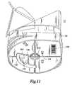
- FIG. 11is a perspective view from the bottom of the dispensing device of FIG. 4 ;
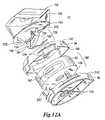
- FIGS. 12A and 12Bare exploded perspective and cross sectional views, respectively, of another embodiment of a dispensing device
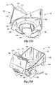
- FIGS. 13A and 13Bare a side view and a perspective view, respectively, of the upper hopper and feed regulator of the dispensing device shown in FIGS. 12A and 12B ;
- FIG. 13Cillustrates the feed nozzle, trap door valve and float
- FIG. 13Dillustrates details of the lid closure
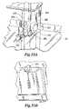
- FIG. 14illustrates a butterfly valve which may be used in place of the trap door valve for purposes of regulating feed between the upper hopper and the lower hopper;
- FIG. 15Aillustrates an automatic guillotine valve
- FIG. 15Billustrates a manual guillotine valve, respectively, which may be used in place of the trap door valve for purposes of regulating feed between the upper hopper and the lower hopper;
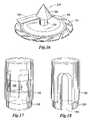
- FIG. 16illustrates a conical plunger which may be used in place of the trap door valve for purposes of regulating feed between the upper hopper and the lower hopper;
- FIGS. 17 and 18illustrate variable sized nozzles comprised of two cylinders which may be used in place of the trap door valve for purposes of regulating feed between the upper hopper and the lower hopper;
- FIGS. 19 and 20illustrate fixed size nozzles formed of a rotating cylindrical member
- FIG. 21illustrates a rotating dose cup which may be used in place of the trap door valve for purposes of regulating feed between the upper hopper and the lower hopper;
- FIG. 22is a perspective view of the dispensing cabinet of FIG. 1 with the drawers and doors removed;
- FIG. 23is a sectional view of the cabinet taken along the lines III—III in FIG. 22 ;
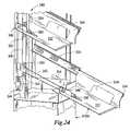
- FIG. 24illustrates the detail of the drawer interlink and counter balance system
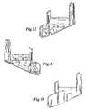
- FIGS. 25A and 25Billustrate the rotatable locking arms used to hold the drawer in the open position
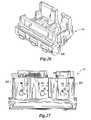
- FIG. 26is a perspective view of the drawer of FIG. 1 with the dispensing devices removed;
- FIG. 27is a top view looking down on the drawer of FIG. 26 ;
- FIG. 28illustrates the details of a locking assembly
- FIG. 29is an electrical schematic illustrating the cabinet and drawer controllers and associated electronics
- FIG. 30is a sectional view taken along the lines A—A of FIG. 27 ;
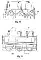
- FIG. 31is a front view of the drawer of FIG. 26 ;
- FIG. 32is a sectional view taken along the lines 32 — 32 in FIG. 31 ;
- FIG. 33is a sectional view taken along the lines 33 — 33 in FIG. 31 ;
- FIG. 34is a right side view of the drawer of FIG. 26 ;
- FIGS. 35A and 35Billustrate details of an override mechanism for unlocking drawers in the event of a loss of power or controller failure
- FIG. 36illustrates a typical bulk medicament stock bottle and label
- FIG. 37illustrates a typical patient prescription label sheet as used by a pharmacy
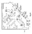
- FIG. 38illustrates a typical pharmacy layout utilizing a medicament dispensing cabinet of the present invention
- FIG. 39illustrates a pharmacy computer system and medicament dispensing cabinets
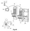
- FIG. 40illustrates a dispensing computer utilizing a cordless bar code scanner in conjunction with dispensing cabinets and open shelving;
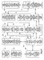
- FIG. 41illustrates a database which may be used in conjunction with the pharmacy computer system shown in FIG. 39 ;
- FIG. 42is a high level flow chart illustrating a patient prescription filling process
- FIG. 43is a flow chart illustrating the user security process shown in FIG. 42 ;
- FIG. 44is a flow chart illustrating the secure pick-up procedure shown in FIG. 42 ;
- FIG. 45is a flow chart illustrating the back end verification procedure shown in FIG. 42
- FIG. 45Ais a flow chart illustrating a partial fill process
- FIG. 45Bis a flow chart illustrating a best fit vial sizing process
- FIG. 45Cis a flow chart illustrating a return to stock procedure
- FIGS. 46A and 46Bis a flow chart illustrating the dispensing cell and dispensing device replenishment function
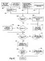
- FIG. 47is a flow chart illustrating a maintenance function
- FIG. 48is a flow chart illustrating an error message routine.
- FIG. 1illustrates a front view of a medicament dispensing cabinet 10 in which a dispensing device 12 of the present invention may be used.
- the medicament dispensing cabinet 10is comprised of a plurality of dispensing drawers 14 each containing three dispensing cells 16 .
- Each dispensing cell 16is comprised of certain electrical and mechanical components (described below) carried by the drawers 14 , which cooperate with a dispensing device 12 .
- Each dispensing cell 16 and dispensing device 12form one type of dispenser although any type of dispenser, such as a Baker Cell, may be carried by drawers 14 . It should be apparent to those skilled in the art that the construction of the medicament dispensing cabinet 10 may be modified to contain fewer or more dispensing drawers 14 to meet different requirements.
- each dispensing drawer 14may be constructed to contain fewer than three dispensing cells 16 or more than three dispensing cells 16 .
- Each medicament dispensing cabinet 10contains a cabinet controller 18 contained behind a door 19 .
- the cabinet controller 18is connected to a dispensing computer, filling workstation, embedded controller, or other control device by an interface cable 20 or by a radio frequency connection used in conjunction with a device such as a PDA (not shown in FIG. 1 ).
- a PDAnot shown in FIG. 1
- a PDAnot shown in FIG. 1
- Additional medicament dispensing cabinets 10may be connected to the dispensing computer or filling workstation by an interconnect cable 22 connected between successive medicament dispensing cabinets 10 to form a medicament dispensing cabinet system. All medicament dispensing cabinets 10 may be controlled by the common dispensing computer or filling workstation.
- a storage area 24is located in the medicament dispensing cabinet 10 behind a door 25 for storing bulk medicament stock bottles, alternative removable dispensing devices 12 , or other materials or inventory.
- FIG. 2Ashows a front-left view of the dispensing drawer 14 (all dispensing drawers 14 being of a similar construction).
- each dispensing drawer 14is comprised of three dispensing cells 16 a , 16 b , 16 c and a drawer controller 46 (see FIG. 3B ).
- Each dispensing cell 16contains a removable dispensing device 12 filled with medicament (not shown in FIG. 2A ).
- the removable dispensing device 12has been removed from the left most dispensing cell 16 a while the removable dispensing device 12 in the right most dispensing cell 16 c is shown in an opened condition (for restocking).
- Each dispensing drawer 14may also comprise an instruction fascia panel 26 , a ledge 28 for temporarily holding a prescription vial 30 or bulk medicament stock bottle (not shown).
- the dispensing drawer's ledge 28may be used by the pharmacy worker to temporarily place empty or full prescription vials 30 while dispensing medicament from another dispensing cell 16 into another prescription vial 30 .
- Each dispensing cell 16includes a chute 32 , chute gate 34 and gate release 36 , as shown in FIG. 2B .
- Each dispensing cell 16also includes a cell display 38 , annunciators (e.g. LEDs) 40 and a cell label 42 as shown in FIG. 2C .
- the cell display 38consists of three alpha-numeric digits for displaying information to the pharmacy worker while the dispensing cell 16 is operating. It should be apparent to those skilled in the art that the cell display 38 may include additional characters, symbols, pictures, etc. to better communicate with the pharmacy worker.
- the techniques to display information on the cell display 38may be varied by the drawer controller in such a manner as to effectively display more than three characters of information to the pharmacy worker.
- the information display techniquesmay include alternating between multiple message segments consisting of three characters, scrolling a message from left to right through the three digits, or changing the intensity of the display characters while either alternating or scrolling the message.
- the annunciator LEDs 40provide immediate status information to the pharmacy worker about the current state of the dispensing cell 16 or dispensing device 12 .
- the dispensing cell 16comprises three different annunciators 40 with each annunciator representing a single state when illuminated.
- the annunciators 40represent the dispensing cell states of ‘READY’, ‘MAINTENANCE’ and ‘ERROR’. Multiple annunciators 40 may be illuminated at any moment in time.
- the annunciators 40are implemented using independent LEDs.
- annunciators 40may also be implemented using incandescent light bulbs integrated into the cell display, or implemented with display icons on the cell display 38 which may or may not comprise a backlight that may be provided by various light sources. Likewise, it should be apparent that additional annunciators 40 may be added to the dispensing cell 16 to present other information to the pharmacy worker.
- the cell display 38 and annunciators 40are connected to and controlled by the drawer controller 46 (shown in FIG. 29 ).
- the cell label 42is attached to the front of each dispensing cell 16 and provides a visual and a machine readable representation, i.e., bar code indicia 44 , of the medicament contained in the removable dispensing device 12 of the dispensing cell 16 .
- a displaythat presents a picture of the product, a sample of the product or a barcode, may be used.
- the dispensing cell bar code indicia 44uniquely identifies the dispensing cell 16 to the dispensing computer or other system components for purposes discussed below.
- the cell label 42also contains textual information representing the medicament in the removable dispensing device 12 . This textual information identifies the medicament to the pharmacy worker and may comprise one or more of the following: a drug number (i.e.
- the cell label 42may also comprise textual information representing a unique drug identification number (e.g., NDC or pharmacy generated ID) to create a unique representation for a medicament that may be supplied under the same drug number but having several different physical representations due to different manufacturers, size variations, color variations or imprints, among others.
- the cell label 42may further comprise a photographic image or illustration of the medicament to allow the pharmacy worker a visual means to verify the medicament dispensed from the removable dispensing device 12 and dispensing cell 16 .
- the cabinet controller 18(See FIG. 1 ) is connected to the drawer controller 46 (See FIG. 3B ) located in each drawer 14 by an electrical or optical cable or any wireless means to communicate instructions and data.
- the cabinet controller 18receives instructions from the dispensing computer or filling workstation and determines the appropriate drawer controller 46 and dispensing cell 16 . The instructions or data are then forwarded to the appropriate drawer controller 46 by the cabinet controller 18 for further processing. After the drawer controller 46 has executed the instruction or processed the data, the drawer controller 46 responds to the cabinet controller 18 .
- the cabinet controller 18in turn responds to the dispensing computer or other control device.
- each dispensing cell 16may consist of its own controller connected to the cabinet controller 18 or directly to the dispensing computer or other control device.
- FIG. 3Ais a left-front perspective view of a dispensing drawer 14 with the instruction panel 26 lowered to provide easier access when removing the removable dispensing devices 12 from the dispensing cell 16 . Also, the removable dispensing device 12 has been removed from the first dispensing cell 16 a . Each dispensing cell 16 further comprises a pair of alignment sockets 50 that mate with alignment pins (discussed below) on the removable dispensing device 12 to properly orient and center the removable dispensing device 12 onto the dispensing cell 16 .
- a motor drive block 54See FIG. 3C
- a motor 55See FIG.
- a hopper disk(discussed below) located within the removable dispensing device 12 which is rotated to dispense medicament from the removable dispensing device 12 .
- the motor drive blockmay be allowed to “float” to allow for misalignment.
- the medicamentfalls from the dispensing device 12 through a dispensing cell drop out opening 56 and passes in front of a medicament sensor 57 (See FIG. 3C ).
- the medicamentis counted by the drawer controller 46 .
- the dispensed medicamentis temporarily stored in the dispensing cell's chute 32 awaiting retrieval by the pharmacy worker.
- the pharmacy workermay release the medicament into the prescription vial 30 by pressing the gate release 36 which will actuate a gate actuator 58 thus opening the chute gate 34 allowing the medicament to fall into the prescription vial 30 .
- the gate actuator 58slowly opens the chute gate 34 to prevent the medicament from spilling over the top of the prescription vial 30 .
- a gate open sensor 59provides feedback to the drawer controller 46 to indicate the current position of the chute gate 34 , which may simply be an ‘open’ or ‘closed’ indication.
- the drawer controller 46will close the chute gate 34 by operating the gate actuator 58 until the gate open sensor 59 indicates the chute gate 34 has returned to the closed position.
- the chute gate 34may be composed of a flexible material to seal the lower end of the chute 32 to prevent any medicament from escaping while being dispensed from the removable dispensing device 12 .
- the flexible gate materialprevents very small medicaments from escaping from the chute 32 while being dispensed.
- the gate actuator 58may be comprised of a motor and cam which lifts the chute gate 34 .
- other meansmay be used to lift or slowly open the chute gate 34 , to thereby open the lower end of the chute 32 to allow medicament to fall from the chute 32 into an awaiting prescription vial 30 or other container.
- an electric solenoidmay be used to open the chute gate 34 .
- the electric solenoidcould have either a linear or rotary motion when actuated.
- the interior surface of the instruction panel 26comprises tabs and slots for the pharmacy worker to insert a medicament lot card 60 to record the medicament 62 provided by stock bottle 64 and contained in the removable dispensing device 12 .
- a pharmacy worker, inventory clerk, or pharmacist, among others,may record date, time, worker initials and other comments while performing routine maintenance on each dispensing cell 16 or removable dispensing device 12 .
- the medicament specific information(e.g. lot number and expiration date) from the bulk medicament stock bottle 64 may also be recorded by the workers.
- the dispensing cell 16further comprises a dispensing device switch 66 (see also FIG. 29 ) which is actuated when the removable dispensing device 12 is inserted and its lid 68 is in the closed position.
- the lid 68 of the removable dispensing device 12contains a tab 70 that mechanically actuates the switch 66 .
- the tab 70will de-activate the switch 66 when either the lid 68 is opened or the removable dispensing device 12 is removed from the dispensing cell 16 .
- the switch 66 and tab 70may be implemented in other ways so as to provide information as to the state of the removable dispensing device 12 being inserted into the dispensing cell 16 or the lid 68 being in the open position.
- an optical or magnetic sensorcould replace the mechanical switch 66 shown in the present embodiment to detect when the removable dispensing device 12 is inserted or its lid 68 is in the open position.
- FIG. 4the dispensing device 12 is shown as being comprised of an upper hopper 80 and a lower hopper 82 . Positioned between the upper hopper 80 and lower hopper 82 is a regulator (not visible in FIG. 4 ), sometimes referred to as a feed regulator, as will be described in detail below.
- FIG. 5is a top view of the embodiment of the dispensing device illustrated in FIG. 4 while FIG. 11 is a bottom view of the dispensing device 12 illustrated in FIG. 4 .
- FIG. 6is an exploded view of the dispensing device 12 illustrated in FIG. 4 .
- FIG. 7is an exploded view of the upper hopper 80 and lid 68 and
- FIG. 10is a cross-sectional view of the dispensing device 12 illustrated in FIG. 4 .
- the upper hopper 80may be comprised of two components, an upper component 84 and a lower component 86 which, when combined define an upper hopper chamber 88 .
- the upper hopper 80has an upper opening 90 , which may be opened or closed depending upon the position of the lid 68 , and a lower opening 92 .
- the upper component 84 and the lid 68may cooperate such that when the lid 68 is opened, a chute is formed to enable easy filling of the upper chamber 88 .
- the upper hopper chamber 88is sized to form a bulk storage area for storing a plurality of medicament and may have a volume on the order of 280 drams.
- the specific components used to form the upper hopper 80are not important.
- the significance of the upper hopper 80is to form the upper chamber 88 which is used for bulk storage of medicament.
- the lower hopper 82is comprised of an upper platform 94 and a lower platform 96 for containing the various other components comprising the lower hopper 82 .
- Those componentsinclude a lower hopper shell 98 having an upper opening 95 and a lower opening 97 .
- a rotating dispensing disc 100Positioned within lower opening 97 is a rotating dispensing disc 100 .
- the lower hopper shell 98defines a dispensing chamber 99 (see FIG. 10 ) which defines the capacity of the lower hopper 82 .
- the dispensing disc 100is rotatable and has a plurality of grooves 101 formed therein, seen partially in FIG. 6 and FIG. 10 .
- the lower hopper shell 98 and dispensing disc 100are connected as shown in FIG. 8 to form a hopper disc assembly 102 .
- a feed regulator 105which in this embodiment is contained within but is not a part of lower hopper 82 , is positioned between the upper chamber 88 and dispensing chamber 99 defined by the lower hopper shell 98 as will be described. It should be noted, however, that although the feed regulator in this embodiment is contained within lower hopper 82 , in other embodiments, the feed regulator may extend from the bottom of upper hopper 80 , or may be a separate component interposed between upper hopper 80 and lower hopper 82 .
- the purpose of the feed regulatoris to regulate the rate at which medicament passes from upper hopper 80 into the dispensing chamber 99 defined by the lower hopper shell 98 , and to insure a minimum continuous flow between upper hopper 80 and dispensing chamber 99 , assuming capacity is available in the dispensing chamber 99 which is more likely the case during operation. Also, the specific components used to form the lower hopper 82 are not important. The significance of the lower hopper is to form the dispensing chamber 99 proximate to the dispensing disc 100 .
- FIG. 6it will be seen that the lower hopper shell 98 together with the upper platform 94 define an upper opening 103 into chamber 99 .
- Lower platform 96defines a lower opening 104 through which medicament dispensed by dispensing disc 100 may exit dispensing device 12 .
- FIGS. 9A , 9 B and 9 Care various views of the components of the regulator 105 , while the relationship between the components of the regulator 105 and the lower hopper shell 98 and dispensing disc 100 are perhaps best seen in FIGS. 8 and 10 .
- the regulator 105is comprised of a cup-shaped member 106 defining a metering section 108 .
- a connecting collar 110extends from the bottom of the cup-shaped member 106 , although other forms of connection may be used.
- the connecting collar 110is designed for connection to the rotating disc 100 as shown in FIG. 8 .
- the cup-shaped member 106(which grips the sides of feed regulator 105 and may also have a detent 113 on collar 110 that fits into a notch 111 ) rotates with the dispensing disc 100 .
- a bottom 112 of the metering section 108is a flat member having a plurality of openings 114 of various sizes formed therein.
- the various sized openings 114are provided to enable metering or feeding of various sized medicaments.
- a selection plate 116 having a selection opening 118is sized to fit within cup-shaped member 106 and cover all of the openings 114 except for one of the openings 114 .
- a plurality of tabs 120(see FIG. 9B ) extending from the bottom of selection plate 116 cooperate with an opening 122 (see FIG. 9A ) positioned in the center of cup-shaped member 106 to hold the selection plate 116 firmly in the bottom of the metering section 108 .
- a plurality of recesses or holes 124(see FIG. 9B ) formed in the bottom of selection plate 116 cooperate with raised portions or pins 126 (see FIG. 9A ) in the metering section 108 to maintain the selection opening 118 in the proper orientation with respect to the selected one of the plurality of openings 114 .
- the selection plate 116is snapped into position.
- dispensing device 12can be tailored to dispense medicaments of differing sizes by simply choosing the proper alignment of the selection opening 118 with the desired one of the plurality of openings 114 .
- the upper surface of the selection plate 116may carry a plurality of stirring devices 128 (see FIG. 9A ) which, in the current embodiment, are raised portions or bubble-like structures.
- Assembly of the dispensing device 12is a matter of lining up the various components and snapping them together.
- the selection plate 116is inserted into cup-shaped member 106 .
- the feed regulator 105is positioned within lower hopper shell 98 and connected to dispensing disc 100 .
- Those componentsare inserted between upper platform 94 and lower platform 96 , which may be designed with tabs to enable them to be held together with a snap fit, and aligning tabs in the upper hopper 80 with slots in the upper platform 94 to enable the upper hopper 80 to be snapped onto lower hopper 82 thus enabling the entire device 12 to be easily and readily assembled, as will be described in greater detail in conjunction with another embodiment of the present invention.
- the lower platform 96may be seen as the device 12 is viewed from the bottom.
- the lower opening 104may be partially covered by a barrier strip 140 .
- Barrier strip 140permits one medicament to fall through opening 104 from one groove 101 at a time.
- a socket 142is designed to receive motor drive block 54 (see FIG. 3C ) to enable rotary motion to be imparted to the dispensing disc 100 .
- the provision of the barrier strip 140 and the imparting of rotary motion to socket 142are known in the art as illustrated, for example, by U.S. Pat. No. 4,869,394, which is hereby incorporated by reference.
- the bottom of lower platform 96also contains alignment pins 144 which cooperate with alignment sockets 50 (see FIG. 3C ) for properly aligning the dispensing device 12 within the dispensing cell 16 .
- the bottom of the dispensing device 12may carry machine-readable indicia 146 .
- any type of identification mechanism appropriate under the circumstancescan be employed such as, for example, radio frequency (RF) tagging of the dispensing devices 12 or, in the case of a user, RF tagging, retinal scanning, scanning finger prints, etc. would all be appropriate identification mechanisms.
- RFradio frequency
- FIGS. 12 and 13Another embodiment of a dispensing device 12 ′ constructed according to the teachings of the present invention is illustrated in FIGS. 12 and 13 .
- the dispensing device 12 ′is comprised of an upper hopper 150 and lid 152 of a similar function, but somewhat different construction, as the upper hopper 80 and lid 68 , respectively.
- the dispensing device 12 ′is also comprised of an upper platform 94 and lower platform 96 which contain the lower hopper shell 98 and dispensing disc 100 as previously described.
- Medicament stored in the upper chamber 88is fed by gravity through a feed nozzle 154 into the dispensing chamber 99 .
- a feed regulator 156restricts the flow of medicament through the nozzle 154 into the dispensing chamber 99 to maintain an optimum medicament quantity level for dispensing by the slotted disc 100 .
- the feed regulator 156is comprised of a trap door valve 158 pivotally connected to nozzle 154 , and further connected to a float 160 .
- the float 160is oriented within the hopper disk 102 where the majority of the medicament concentrates as the dispensing device 12 ′ operates. As the hopper disk 102 rotates in the direction shown by arrow 162 , the medicament migrates to the outer edge of the hopper disk 102 and is pulled upward by the slotted dispensing disk 100 and into the vicinity of the float 160 . The leading edge of the float 160 is designed to direct the medicament flow underneath the float 160 to thereby allow float 160 to “ride on” the medicament. The level of medicament in dispensing chamber 99 determines the position of float 160 .
- the float 160As the medicament level in the dispensing hopper disk decreases, the float 160 is lowered which opens the valve 158 , allowing medicament from the upper chamber 88 to flow through the feed nozzle 154 and into the dispensing chamber 99 .
- the valve 158opens as a result of gravity and the weight of the medicament.
- the float 160As the medicament level rises, the float 160 also rises forcing the valve 158 toward its closed position.
- the valve 158may be designed so that a portion of the feed nozzle 154 is never closed by the valve 158 as indicated by numeral 164 and referred to as the feed regulator primer (See FIG. 13C ).
- the feed regulator primer 164allows medicament to flow into the dispensing chamber 99 when the upper hopper chamber 88 is initially filled with medicament.
- a probe 155responsive to the valve 158 , may be provided for agitating the medicament as the valve 158 moves up and down.
- Another mechanism to allow a small amount of medicament to continuously flow into the dispensing chamber 99 as the hopper disc assembly 102 operatesis to remove a portion 166 of the feed nozzle 154 as shown in FIGS. 12A , 13 B, and 13 C.
- valve 158Because of the pivot connection between valve 158 and feed nozzle 154 , there is a natural tendency for the valve 158 to remain open under the influence of gravity. The valve 158 is closed by the medicament randomly becoming stacked and layered between the regulator float 160 and disk 99 as the medicament rotates inside the hopper disk assembly 102 .
- the preferred embodimentsdisclose a dispensing device which eliminates the overfilling of the dispensing chamber 99 by virtue of the feed regulators 105 , 156 maintaining an ideal quantity of medicament within the dispensing chamber 99 .
- the dispensing disk 100is able to operate efficiently and effectively.
- the medicamentis not crushed, jammed or damaged by the rotating dispensing disk 100 .
- the medicamentis allowed to freely tumble within the rotating hopper disk assembly 102 and is gently agitated into the dispensing disk slots 101 for dispensing.
- FIGS. 13A and Billustrate the upper hopper 150 and lid 152 .
- the upper hopper 150defines an upper hopper area 168 and a lower hopper area 170 .
- the lid 152is comprised of a first lid part 171 and a second lid part 172 .
- the upper hopper 150is, in general, filled from the top through the lid 152 and empties through the feed nozzle 154 .
- the first lid part 171has sides 175 creating a funnel to assist the worker during the replenishment of the dispensing device 12 ′ from medicament stock bottles. Ridges 177 on the surface of the first lid part 171 guide the medicament into the upper hopper area 170 while the worker pours the medicament from the medicament stock bottle.
- the large opening created by the unique design of the upper hopper 150 and its lid 152allows the worker to easily pour medicament from all size medicament stock bottles used in the pharmacy.
- the workerplaces the lid parts 171 and 172 in a closed position and presses down on the rear center of the lid part 172 .
- a pair of curved lid snaps 180deflect a lip 182 outward.
- the lid snaps 180snap into a latched position under lip 182 while lid sides 175 are restricted from further movement by a pair of lower lid stops 184 .
- the lower lid stops 184restrict the movement of the first lid part 171 into the upper hopper area 168 .
- the workerthen presses on the front of the second lid part 172 such that a latching tab 187 (See FIG. 13D ) is deflected by its leading edge and snaps under an upper lid catch 188 .
- the lid 152prevents medicament from exiting the upper hopper chamber 88 while device 12 ′ is being transported.
- the upper hopper area 168 and lower hopper area 170are constructed to create a bulk storage chamber without abrupt interior edges or ledges for medicament to become lodged in or on. All surfaces of the lower hopper area 170 are sloped and curved to eliminate edges and ledges that prevent medicament from flowing into the lower section of the lower hopper area 170 which becomes the feed nozzle 154 .
- the upper hopper 150relies completely upon gravity to affect medicament flow from the upper hopper area 168 and lower hopper area 170 into the feed nozzle 154 .
- the float 160is inserted through a center opening in the upper platform 94 .
- Upper hopper latching tabs 194are aligned with and inserted into slots 192 .
- the latch tabs 194is locked to the upper platform 94 .
- the hopper disk assembly 102is inserted into the lower platform 96 and the upper platform 94 is aligned by the worker.
- An upper platform housing pin 198is oriented and aligned with a lower platform socket 200 and inserted underneath the platform socket 200 .
- platform latch slots(not shown) align with platform latches 202 .
- the workerpresses the upper platform 94 onto the lower platform 96 ; the platform latches 202 are deflected by the platform latch slots and come to rest behind the slots, latching the two pieces together.
- Hopper tension springs 204(Seen best in FIG. 6 ) located on the upper platform 94 maintain a constant pressure between the hopper disk assembly 102 and upper platform 94 once the upper platform 94 is latched to the lower platform 96 .
- a lower hopper sealing ring 206 and hopper spring 208prevent medicament inside the dispensing chamber 99 from migrating outside of the device 12 ′ during operation or transportation.
- FIG. 14illustrates a butterfly valve 214 which may be used in place of the trap door valve previously described for purposes of regulating feed between the upper hopper 80 and lower hopper 82 .
- the butterfly valve 214is connected to a rotatable arm 216 which is positioned within an opening 218 such that upon rotation of the arm 216 , the position of the butterfly valve 214 within opening 218 is adjusted.
- Rotatable arm 216has a flag portion 220 extending outwardly therefrom.
- flag portion 220is capable of interacting with medicament held within dispensing chamber 99 so as to rotate arm 216 .
- the flag 220points substantially downward thus holding the butterfly valve 214 in an open position.
- the flag 220begins to move from the vertical downward position toward a horizontal position thereby moving the butterfly valve 214 to close the opening 218 .
- the butterfly valve 214may be designed such that even in the fully closed position, a portion of the opening 218 remains unblocked by the butterfly valve 214 to insure some minimal amount of continuous flow.
- a guillotine valve 226is illustrated for controlling the opening 218 .
- the guillotine valve 226is connected to an arm 228 which interacts with the volume of medicament in the dispensing chamber 99 to control the area of the opening 218 that is restricted by the guillotine valve 226 .
- the guillotine valve 226is pivotally connected at an angle to the feed nozzle such that it is urged in one direction by gravity and urged in the other direction by arm 228 .
- Guillotine valve 226may be configured or connected such that a portion of the opening 218 is always open.
- FIG. 15Billustrates another type of guillotine valve 230 which may be used to control the opening 218 .
- the guillotine valve 230 in FIG. 15Bis adjusted by the user prior to being put into operation.
- the guillotine valve of FIG. 15Bmay be thought of as a fixed valve as it is manually set by the user and that setting does not change based on the level of medicament in the dispensing chamber 99 .
- FIG. 16illustrates a conical plunger valve 234 which may be used in place of the previously described valves.
- the plunger valve 234is comprised of a cone 236 which is capable of riding up and down on shaft 238 .
- Shaft 238is connected to the dispensing disk 100 .
- Cone 236may also carry one or more wings 240 , angled in the direction of motion as shown in FIG. 16 .
- the wing 240interacts with the medicament present in the dispensing chamber 99 .
- the greater the volume of medicament in the dispensing chamber 99the higher the cone 236 on shaft 238 , thereby tending to close the opening 218 , not shown in FIG. 16 .
- the lower the level of medicament in the dispensing chamber 99the lower the cone 236 on shaft 238 , such that the cone 236 is withdrawn from opening 218 thereby allowing a greater volume of medicament to enter the dispensing chamber 99 .
- FIGS. 17 and 18illustrate variable sized nozzles comprised of two cylinders which may be used in place of the trap door valve for purposes of regulating feed between the upper hopper 80 and the lower hopper 82 .
- two cylinders 242 and 244each have a plurality of openings formed therein.
- the cylinders 242 and 244are capable of nesting within one another such that upon relative rotation the size of the openings 246 can be manually set by the user.
- FIG. 18illustrates a similar embodiment.
- cylinders 250 and 252each have a single opening such that the size of an opening 254 can be manually set by the user through relative rotation of the cylinders 250 and 252 .
- FIGS. 19 and 20illustrate fixed size nozzles formed in rotating cylinder members 260 and 262 , respectively, carried by the dispensing disk 100 .
- the cylinder 260has an opening 264 formed therein while the cylinder 262 has a larger opening 266 formed therein.
- the openings 264 and 266are sized to enable a desired volume of medicament to be fed to the dispensing grooves 101 .
- FIG. 21illustrates a rotating dose cup 268 which is connected to and rotates with dispensing disk 100 .
- the dose cup 268is mounted at an angle e.g. 45°, with respect to the dispensing disk 100 .
- the volume of medicament fed to the dispensing grooves 101can be controlled.
- FIG. 22a perspective view of the dispensing cabinet 10 is illustrated in which the drawers 14 and the doors 19 and 26 have been removed.
- the dispensing cabinet 10is comprised of a frame 330 .
- the frame 330carries a plurality of shelves 332 equal in number to the number of drawers 14 .
- the shelves 332are each carried by a pair of drawer glides 334 which enable the shelves 332 to move between a fully closed position, in which the drawer is retracted and positioned within the frame 330 , and a fully open position in which the shelf 332 extends outward from the frame 330 .
- the frame 330 together with the shelves 332define a plurality of drawer openings 336 .
- the shelves 332 and drawer openings 336are configured so that each shelf may carry a drawer 14 . In that manner, the drawers 14 can be moved between their fully closed and fully opened positions.
- FIG. 23is a sectional view of the cabinet 10 shown in FIG. 22 taken along the lines 23 — 23 .
- each of the shelves 332is mounted at an angle with respect to the horizontal such that the front of the shelf, and hence the front of each drawer, is lower than the rear of each shelf and the rear of each drawer.
- a drawerwhen a drawer is moved to its fully open position, it extends downwardly and outwardly from the frame 330 , whereas when each drawer is in its fully closed position, it remains at the same downwardly extending angle, but is maintained substantially completely within the frame 330 .
- substantially completelyrefers to the fact that the shelf 332 and drawer glides 334 are retracted such that no portion of the drawer glides 334 is exposed, even though portions of the drawer 14 , as seen in FIG. 1 , may extend beyond the frame 330 .
- FIGS. 23 and 24Illustrated in FIGS. 23 and 24 is a drawer interlink and counterbalance system 340 .
- the interlink and counterbalance system 340is comprised of a flexible member 342 having one end connected to a tensional spring 344 and another end 346 connected either to the frame 330 or to the drawer 14 positioned furthest from the tensional spring 344 .
- the flexible member 342runs behind each of the shelves 332 .
- each shelf 332carries a guide member 348 which travels with the shelf 332 and, as shown in FIG. 24 , is positioned to the left of flexible member 342 .
- Positioned above and below each guide member 348is an upper roller 350 and lower roller 352 , each of which is carried by the frame 330 .
- the drawer glides 334enable the shelf 332 to be moved from the fully closed to the fully open position.
- the guide member 348engages flexible member 342 between the upper roller 350 and lower roller 352 .
- the tensional spring 344is played out enabling the drawer to move to its fully open position.
- the tensional spring 344exerts a force through member 342 which creates counterbalance force 354 opposing the gravitational forces on the drawer 14 .
- the flexible member 342is under constant tension by virtue of the tensional spring 344 .
- the force exerted by the tensional spring 344may be calculated to support the average weight of a drawer, which is approximately 23 pounds. Because the guide member 348 pulls the flexible member 342 in a manner to cause the flexible member 342 to engage both the upper roller 350 and lower roller 352 , the force of the tensional spring 344 is doubled. Most of the drawer weight is supported by the frame 330 through drawer glides 334 . The outward force component is equal to the sine of the drawer angle 356 .
- the force of the tensional spring 344 required to support a drawer 14is found using the formula:
- a spring force of between 4.5 and 5 poundswill normally be adequate to counterbalance a drawer, including drawer glides, weighing approximately 23 pounds.
- the counterbalance force 354restricts the rate of descent of the drawer, allowing the worker to maintain control of the drawer as it is opened. Furthermore, the counterbalance force 354 also makes it easier to move the drawer from its fully opened to its fully closed position.
- the counterbalance force 354may be generated using other types of devices such as coil springs, helical springs, leaf springs, weights, pneumatic cylinders, etc.
- the system 340is referred to as an interlink and counterbalance system because the flexible member 342 and tensional spring 344 may be sized such that only one drawer 14 may be fully opened at a time, per cabinet 10 .
- the system 340not only provides a counterbalance force for each drawer, but provides an interlink between the drawers such that only one drawer may be opened at a time.
- the rotatable locking armspivot about pivot point 360 and are weighted at one end such that when the shelf 332 is in the fully opened position, the rotatable locking arms 358 clear the drawer glide 334 and pivot about pivot point 360 such that one end of the rotatable locking arm abuts the drawer glide 334 while the opposite end abuts a portion of the shelf 332 . In that manner, the shelf 332 , and hence the drawer, are automatically locked into the fully opened position as soon as the drawer 14 assumes the fully opened position without any further action needed by the user.
- the userrotates both rotatable locking arms 358 into a position parallel to the drawer glide 334 as shown in FIG. 25A .
- the counterbalance force 354will start pulling the drawer toward its fully closed position and, with additional force supplied by the user, can be easily moved to its fully closed position where it will be locked in place, as described below.
- the flexible member 342may be implemented using a plastic coated stranded steel cable although other flexible materials can be used. It is further anticipated that if a flexible member 342 is chosen which also has elastic properties, such as a rubber strand, then the tensional spring 344 may be eliminated. In such an embodiment, pulling on the flexible member 342 will place the member in a state of expansion, and the spring-like properties of the member will produce the necessary counterbalance force.
- the drawers 14are shown in greater detail in conjunction with FIGS. 26 , 27 and 30 – 34 while a locking assembly is illustrated in conjunction with FIGS. 3B , 28 and 29 .
- the drawer 14 carried by each shelf 332has a locking assembly which includes a latch roller 370 which engages a strike plate formed by a notch 372 in member 392 . (See FIG. 35A .)
- the latch roller 370engages strike plate notch 372 so as to lock the drawer 14 in its fully closed position.
- an emergency unlatch rod 373is also visible in FIG. 3A , discussed below.
- a manual override of the drawer locking systemis provided.
- the bottom of emergency unlatch rod 373is accessible within storage area 24 .
- portions along the rodpush each latch roller 370 away from its associated notch 372 .
- a mechanical lockcould be placed on the movable member 373 to control access to the manual override.
- the latch roller 370is carried by a latch pawl 374 .
- Latch pawl 374is connected to latch arm 376 at a first pivot point 377 .
- the other end of latch arm 376is connected to a solenoid 378 . (See FIG. 3B ).
- Latch pawl 374is also pivotally connected to a fixed member 380 at a second pivot point 381 .
- a latch pawl return spring 382is connected between the latch pawl 374 and the fixed member 380 . The connection between spring 382 and latch pawl 374 is at a position opposite to the first pivot point 377 with respect to the second pivot point 381 .
- the cabinet controller 18forwards the command to the appropriate drawer controller 46 which acknowledges receipt of the command by returning a command response to the control computer via the cabinet controller 18 .
- the drawer controller 46then begins to monitor a drawer release switch 386 (see also FIG. 26 ).
- the drawer controller 46issues a command to activate the solenoid 378 (see also FIG. 3B ).
- the solenoid 378is activated, the latch arm 376 will be pulled downward in FIGS.
- latch pawl 374rotates counterclockwise about second pivot point 381 , overcoming the opposing tension applied by the latch pawl return spring 382 .
- the rotation of the latch pawl 374counterclockwise as shown in FIGS. 3B and 28 , moves the latch roller 370 away from and clear of the strike plate notch 372 , thereby unlocking the drawer 14 from the frame 330 .
- the drawer release switch 386is positioned on the drawer 14 so as to allow the worker to positively grip the drawer 14 while guiding and pulling the drawer 14 to its fully opened position.
- the activation of solenoid 378can be timed so that the solenoid is not burned out should the user continue to hold drawer release switch 386 in the closed position.
- the drawer controller 46monitors a drawer position switch 388 (see also FIGS. 3B and 28 ). Once the drawer 14 has been unlocked, and the drawer 14 begins to move away from the frame 330 , the drawer position switch 388 will change state. After a slight delay, the drawer controller 46 will disable drawer release switch 386 .
- FIGS. 30–34illustrate various views of a drawer 14 .
- each of the drawers 14has a sloped bottom thereby enabling each of the drawers 14 to be received by one of the shelves 332 as will now be described.
- each drawercontains a protrusion 384 (See FIG. 27 ) which extends through an opening 394 in shelf 332 (See FIG. 24 ).
- the other side of the drawerhas a catch tab 385 (See FIG. 27 ).
- a spring tab 396 carried by shelf 332grips the bottom rear of the drawer. To remove a drawer, spring tab 396 is pulled downward while the left side of the drawer is lifted upward away from shelf 332 . When the left side of the drawer is sufficiently high above shelf 332 , the protrusion 384 can be moved from opening 394 by lifting the drawer up and to the left.
- Other mechanisms for connecting the drawer to the shelfcan be devised by those skilled in the art. The particular mechanism for connecting the drawer to the shelf is not important for purposes of the present invention.
- FIG. 36illustrates a typical bulk medicament stock bottle 64 as supplied to a pharmacy by a medicament manufacturer.
- the bulk medicament stock bottle 64will generally contain a stock bottle bar code indicia 287 which is unique to the medicament and may also contain a package size code which represents the quantity of medicament in the bulk medicament stock bottle 64 .
- the bulk medicament stock bottle 64also contains textual information 288 specific to the batch or lot of medicament contained within bottle 64 .
- a lot number 289 and expiration date 290are printed by the manufacturer when the medicament is packaged into the bulk medicament stock bottle 64 .
- the lot number 289is used by the pharmacy to track medicament dispensed to patients should the medicament be recalled by the manufacturer.
- the expiration date 290is the date by which the medicament must be repackaged into a patient prescription and sold by the pharmacy.
- FIG. 37illustrates a patient prescription sheet 291 printed by the pharmacy computer system for each patient prescription.
- the patient prescription sheet 291comprises a vial label that is applied to the prescription vial 30 , prescription bar code indicia 292 , and medicament bar code indicia 293 , among others.
- the prescription bar code indicia 292is a machine readable indicia and represents the patient prescription and allows a dispensing computer 400 (See FIG. 38 ) to retrieve various elements of the patient prescription transmitted to the dispensing computer 400 by an interface to the pharmacy computer system.
- the various elements of the patient prescription electronically transmittedmay comprise the prescription information (e.g. prescription number, refill number, number of refills, quantity), medicament information (e.g.
- prescription labelas required by the particular state pharmacy laws, patient information, prescribing doctor information, order grouping information used to associate all of the patient prescriptions, a bag label to be placed on the completed prescription bag containing the prescription vial 30 and other prescription instruction sheets or coupons, among others.
- FIG. 38illustrates a layout of a typical pharmacy utilizing the medicament dispensing cabinet 10 , open shelving 298 , dispensing computer 400 , cordless bar code scanner 294 (RF, IR, ultrasonic, etc.), handheld computer or handheld computer which incorporates a bar code scanning device 296 , filling workstation 402 , pharmacy system 403 , data entry workstation 404 , pharmacist checking workstation 406 , inventory workstation 410 , an area for completed prescriptions generally known as ‘will call’ area 412 and a check out station 414 .
- RFradio frequency scanner
- one or more duplicate medicament dispensing cabinets 10 , dispensing computers 400 , filling workstations 402 , pharmacy systems 403 , data entry workstations 404 , pharmacist checking workstations 406 , inventory workstations 410 , ‘will call’ areas 412 and check out stations 414are also intended to be within the scope of the present invention, which may be used to simultaneously interact to properly fill and verify patient prescriptions.
- multiple medicament dispensing cabinets 10 , cordless bar code scanners 294 and handheld computers or handheld computers 296 which incorporates bar code scanning devicesmay be used simultaneously to properly replenish, operate and maintain the removable dispensing device 12 and dispensing cell 16 .
- each worker 416 in the pharmacyis assigned an identification badge 418 or bracelet (not shown) which contains bar code indicia 420 that can be scanned by a bar code reader 422 , cordless bar code reader 294 or handheld computer or handheld computer which incorporates a bar code scanning device 296 or can be manually entered into one of the computers.
- FIG. 39further illustrates a medicament dispensing system showing the various workstation configurations and functional interconnection of the components as they are used to implement the processes of filling a patient prescription, replenishing the removable dispensing devices 12 , and maintaining or cleaning the dispensing devices 12 .
- the filling workstation 402 , dispensing computer 400 , and the remainder of the pharmacy computer systemare interconnected via a network providing intercommunication of files, data and instructions among the connected computers and workstations.
- the remainder of the pharmacy computer systemmay be further comprised of the data entry workstation 404 , checking workstation 406 , inventory workstation 410 , and a printer 424 .
- the filling workstation 402comprises a computer, display, and keyboard although, as previously mentioned, the terms “computer”, “workstation” or the like are to be construed to mean any type of control device.
- the filling workstation 402is responsive to the bar code reader 422 and may control a printer such as prescription label printer 424 .
- a radio frequency transmitter/receiver 428may be provided for communication with the cordless bar code scanner 294 and the handheld computer or handheld computer which incorporates a bar code scanning device 296 .
- the filling workstation 402is connected to a first medicament dispensing cabinet 10 by the cable 20 . Additional medicament dispensing cabinets 10 ′ may be connected to the first medicament dispensing cabinet 10 by the cable 22 .
- FIG. 40is an illustration of a medicament dispensing system showing the filling workstation 402 implemented by utilizing a dispensing computer 400 to control the processes of filling a patient prescription, replenishing the removable dispensing devices 12 , and maintaining or cleaning the dispensing devices 12 .
- the dispensing computer 400 , and pharmacy computer systemare interconnected via a central network providing intercommunication of files, data and instructions.
- the dispensing computer 400is further connected to the radio frequency transmitter/receiver 428 for communication with, for example, cordless bar code scanner 294 and handheld computer or handheld computer which incorporates a bar code scanning device 296 .
- the dispensing computer 400may control the prescription label printer (not shown in FIG. 40 ).
- dispensing computer 400may be combined into a single unit to perform the same operations.
- radio frequency transmitter/receiver 428may be combined into a single unit to perform the same operations.
- the filling workstation 402 and dispensing computer 400 as illustrated in FIGS. 39 and 40 , respectively,are shown as separate components. Is should be apparent to those skilled in the art, however, that the functions of the filling workstation 402 and dispensing computer 400 are similar in scope and in general are interchangeable with each other. Additionally, although in the embodiments shown, workers 416 identify themselves by badges or bracelets carrying bar codes, other forms of identification may be used including radio frequency (RF) tags, among others.
- RFradio frequency
- FIG. 41is a representation of a database 430 , utilized by the dispensing computer 400 and by the pharmacy workers.
- the database 430has several fields, certain of which represent specific information about a specific worker.
- the database 430has a personnel database 432 which includes fields representing the worker's name or initials, password, badge or bracelet indicia, worker classification or security level, medicament access security level, among others.
- Each workeris also assigned configurable settings that allow them the ability to fill prescriptions, replenish or access the removable dispensing devices 12 , and retrieve another worker's fill prescription request.
- the worker classificationmay be selected from a group which comprises a pharmacy technician, inventory clerk, pharmacist, or pharmacy manager (sometimes collectively referred to as a pharmacy worker). Each worker classification allows the worker to access or perform different functions or procedures within the dispensing computer 400 . In addition, the worker classification defines a hierarchy to operating the dispensing computer 400 .
- the pharmacy managerhas the highest security level and is allowed access to all dispensing computer functions, including maintaining workers and their worker classifications.
- the pharmacistreports to the pharmacy manager and has the ability to perform tasks and override errors created by either a pharmacy worker or inventory clerk or other pharmacist but is restricted from modifying the worker database or each worker's classification.
- the pharmacy workeris allowed to operate the dispensing computer 400 to fill patient prescriptions; but may not be given access to all medicaments or may not be given the ability to replenish the removable dispensing devices 12 or perform maintenance (including cleaning) of dispensing cells 16 , collectively referred to as servicing.
- the inventory clerkis allowed to replenish the dispensing devices 12 , remove and replace removable dispensing devices 12 or return medicament to a dispensing device 12 .
- each workeris given a drug access level based on their experience and training.
- the medicaments used in a pharmacyare classified by the Food and Drug Administration (FDA) as being Over-The-Counter (OTC), prescription (Rx), controlled substance (C2, C3, C4 or C5) or narcotic. These classifications determine the level of training or restrictions in handling while dispensing patient prescriptions or replenishing the removable dispensing device.
- FDAFood and Drug Administration
- OTCOver-The-Counter
- prescriptionRx
- controlled substanceC2, C3, C4 or C5
- narcoticnarcotic.
- the dispensing computer 400maintains two levels of drug access security. If a worker is assigned an access security level of ‘Controlled’, they may access any medicament within the dispensing system. If a worker does not have the ‘Controlled’ access security level, the dispensing computer 400 will restrict their access to only the OTC or prescription drugs.
- the dispensing computer 400will check the access level required for all medicaments in an entire dispensing drawer 14 before the worker will be allowed access. If the drawer contains a ‘Controlled’ medicament and the worker does not have access to ‘Controlled’ medicaments, the worker will not be allowed to replenish, clean or maintain the removable dispensing device 12 or dispensing cell 16 requested by the worker.
- the allocation of responsibility/accessmay change from pharmacy to pharmacy or periodically within a pharmacy. Security can thus be individualized based on employees as discussed above or based on dispensers (dispensing cell 16 plus dispensing device 12 ) as discussed below.
- the dispensing computer 400also maintains a database 434 of each medicament that may be dispensed from the medicament dispensing cabinet 10 .
- Each medicamentis assigned a drug access level that corresponds to the user drug access level.
- the medicament databaseis typically maintained only by a pharmacist or pharmacy manager.
- the dispensing computer 400also maintains a database 436 for each dispensing cell 16 comprising dispensing cell indicia, e.g. bar code 44 , textual drug description for display, textual drug number (NDC or DIN), removable dispensing device indicia 146 (see FIG. 11 ), medicament stock bottle indicia 287 (see FIG. 36 ), among others.
- Each dispensing cell 16may be associated to several medicament stock bottle indicia 287 .
- the database 430also contains a prescriber database 440 , patient database 442 , order database 444 and transaction database 446 .
- a replenish database 448 and site activity database 450are provided, as are site information database 452 , device type database 454 and site device database 456 as shown in FIG. 41 .
- the present inventionovercomes the problems inherent in other medicament dispensing units and provides a medicament dispensing cabinet 10 utilizing a removable dispensing device for dispensing specific quantities of bulk medicament 62 to fill a patient prescription.
- the medicament dispensing cabinet 10may utilize any of a wide variety of displays to display and insure the proper pharmacy worker is retrieving the proper medicament from the dispensing cell 16 for the patient prescription being filled by the dispensing cell 16 .
- each medicament dispensing cell 16may contain the alpha-numeric display 38 for indicating the worker's identification by displaying either the worker's initials or another code that is easily recognized by the pharmacy worker.
- the medicament dispensing cell 16may use the display 38 for clearly communicating various types of information to the pharmacy worker.
- the drawer locking mechanismmay be used for limiting access to the dispensing cell 16 and removable dispensing device 12 .
- the electronically controlled chute gate 34 and gate release 36may be used to insure medicament retrieval by the proper pharmacy worker 416 .
- the dispensing cell label 42 with bar code indicia 44may be used to positively identify the dispensing cell 16 , removable dispensing device 12 , and medicament 62 .
- the medicament dispensing cabinet 10 of the present inventionincludes a means to positively indicate the current state of each dispensing cell 16 which includes displaying the operation being performed, the pharmacy worker associated with the task to be performed and other state specific information needed by the pharmacy worker to efficiently operate the medicament dispensing equipment.
- the dispensing cell 16can also be operated in a “Baker Cell mode” in which the dispensing cell 16 simply counts medicament.
- the present inventionincludes a method for directing and tracking the patient prescription filling process and verifying the proper steps are taken by a pharmacy worker and recording the medicament and prescription filling details which occur during the patient prescription filling process.
- the dispensing cell 16is idle, waiting for instruction, e.g. from the dispensing computer 400 .
- the prescription filling processmay be initiated in one of several ways as shown in FIG. 42 .
- a usermay press the “local” button on a cordless bar code reader followed by scanning or entering a cell number at 460 .
- the processcould begin by entering a command on a host computer or controller to enter the “local” mode as shown at 459 .
- the systemvalidates the cell number.
- the usermay scan a drug number bar code on a prescription label which causes the system to validate the drug number, translate the drug number to the appropriate cell number, and validate the cell number.
- prescription fillingcould be initiated electronically by a host computer, or a controller such as the AutoLinkTM controller (available from McKesson Automation Systems) as shown at 463 .
- the systemdetermines if user security is enabled at 464 . If user security has been enabled, then a user security procedure is performed as shown by block 466 . That procedure is described in detail in conjunction with FIG. 43 . After performance of the user security procedure, or if the user security was not enabled, the process proceeds with block 470 .
- the dispensing computer 400instructs the appropriate dispensing cell 16 of the proper quantity of medicament 62 to dispense at 470 . As the medicament 62 is dispensed, the cell display 38 associated with the dispensing cell 16 indicates the present quantity dispensed into the chute 32 located in the dispensing cell 16 .
- the processcontinues with decision 472 where a determination is made if the secure pick up procedure is enabled. If yes, the secure pick up procedure is performed as shown by block 474 and described in detail in conjunction with FIG. 44 . After the secure pick up procedure has been performed, or if the secure pick up procedure has not been enabled, the worker retrieves the medicament from the dispensing cell chute as shown by 476 .
- the dispensing cell's gate release 36is enabled after the appropriate worker and dispensing cell identification security checks have been completed. Once these security verification checks have been successfully completed, the pharmacy worker 416 may press the gate release 36 (with the prescription vial 30 under the chute 32 ), which opens the electronically operated dispensing chute gate 34 , allowing the medicament 62 to fall from the dispensing cell's chute 32 into the patient's prescription vial 30 .
- the user security procedure 466is illustrated in FIG. 43 and is used to insure the worker security level will allow the worker to dispense medicament from a dispensing cell 16 based on medicament configuration settings maintained in the database in, e.g. the database 430 .
- the dispensing computer 400directs the worker to scan their worker bar code indicia 420 on their identification badge 418 or bracelet.
- Other forms of user identificationthat could be implemented are an RF tag assigned to each user, fingerprint recognition, retinal scan, or other alternatives known in the art to specifically and uniquely identify an individual.
- the dispensing computer 400will verify the pharmacy worker 416 has a medicament access level sufficient to dispense the medicament from the dispensing cell 16 by going through the following sequence of questions:
- the steps required for verifying the pharmacy worker or pharmacist which originally initiated the dispensing event and for verifying that the cell 16 has the proper medicament access level, i.e. the secure pick up procedure 474 ,are shown in FIG. 44 .
- the workeris instructed by the dispensing computer 400 , cordless bar code reader 294 , or handheld computer or handheld computer which incorporates a bar code scanning device 296 at 484 to scan the dispensing cell bar code indicia 44 to identify the dispensing cell 16 from which medicament 62 is being retrieved by the pharmacy worker.
- the dispensing computer 400then directs the worker to scan the worker bar code indicia 420 of the worker's identification badge 418 or bracelet at 488 .
- the dispensing computer 400verifies at 490 , 492 and 494 that the medicament access level of the worker will allow retrieval of the medicament in the dispensing cell 16 .
- the dispensing computer 400then verifies if the worker picking up the dispensed medicament is the same worker that initiated the dispensing event by checking if the dispensing cell was temporarily assigned to this worker at 496 . If there is a match, the dispensing computer 400 will enable the gate release 36 by sending instructions to the drawer controller 46 at 498 .
- the dispensing computermust check the worker database configuration setting to verify the worker seeking to retrieve the medicament has permission to retrieve a patient prescription initiated by another worker. If the worker is allowed to pick up another worker's prescription as shown at 500 , the gate release 36 is enabled for the dispensing cell 16 .
- the status of the dispensing cellmay change and this state change may be indicated on the appropriate dispensing cell annunciator LED 40 and/or the cell display 38 .
- the dispensing cell 16may indicate to the pharmacy worker 416 when the removable dispensing device 12 should be replenished by illuminating the ‘MAINTENANCE’ annunciator LED 40 and also displaying additional replenishment message information on the cell display 38 . Should a problem be detected in the dispensing cell 16 or dispensing device 12 , need for this type of service may be indicated using the ‘ERROR’ annunciator LED 40 in combination with messages displayed on the cell display 38 .
- the patient prescription filling taskis subdivided further and requires the dispensing computer 400 to allow a first pharmacy worker to initiate the medicament dispensing while a second pharmacy worker retrieves the medicament 62 from the dispensing cell 16 upon completion as shown in FIG. 44 .
- the dispensing computer 400maintains a pharmacy worker database 432 of security levels for each worker that may be set which allows a worker to retrieve medicament from the dispensing cell initiated by another worker. This capability allows a second pharmacy worker to initiate the secure pickup of a patient's prescription from a dispensing cell while maintaining the verification and pharmacy worker auditing trail needed in busy pharmacies.
- the same security level for both fill and pickupcan be enabled or disabled independently.
- FIG. 45Another level of pharmacy worker auditing captured by the dispensing computer 400 or other computer within the pharmacy network is the back end verification procedure shown in FIG. 45 . That procedure requires the pharmacy worker identification bar code indicia 420 to be scanned immediately after the medicament 62 retrieval from the dispensing cell 16 as shown in FIG. 45 at 502 .
- the dispensing computer 400receives a signal from the medicament dispensing cabinet 10 indicating the dispensing cell 16 from which medicament 62 was retrieved. This signal is associated with the pharmacy worker 416 identified by the worker identification badge scanned and verifies the correct pharmacy worker retrieved the patient prescription.
- the user IDis assigned to the filled and picked up prescription as shown at 503 .
- the back end verification procedurecan be expanded to allow the worker the capability to instruct the dispensing computer 400 when the medicament 62 retrieved from the dispensing cell 16 will be returned to the removable dispensing device 12 .
- An example of such a “return to stock procedure”is illustrated in FIG. 45C .
- This procedureprovides the user with a way of dealing with a patient canceling a prescription, a prescription not being picked up, prescription errors that may be caught after the prescription has been initiated for dispensing, or returning stock after a cycle count.
- the return to stock portion of the back end verification processinsures accurate inventory quantity records while also insuring the dispensing device's medicament integrity by directing, tracking and verifying the worker while performing the steps of the return to stock task.
- the back end verification procedurecan be further expanded to allow the worker to handle partial prescription fills when the dispensing device runs empty while dispensing a patient prescription as shown in FIG. 45A .
- a dispensing eventoccurs at 306 .
- this dispensing locationhas been emptied by the partial fill, which may be picked up at 314 .
- a decisionis made at 316 if the fill should be completed. If not, the process concludes; if yes, another location with the same drug is searched for at 318 . If no automated dispensing device is located, instructions are provided at 320 to complete filling the prescription by hand. If, on the other hand, an automated dispensing device is identified, then a dispensing event occurs at 322 for the remaining quantity.
- the partial fill processcan track the identification of both the worker retrieving the first prescription portion from the dispensing cell 16 and the worker completing the second prescription portion, or the worker retrieving the second prescription portion from another dispensing cell 16 , and finalizing the complete prescription before it is checked by the pharmacist. Additional labels for multiple vials can be prepared as needed.
- the dispensing computer 400will inform the worker of the vial size needed for each portion of the complete prescription.
- the dispensing computer 400maintains a site configuration allowing a patient prescription to be broken into ‘Best Fit’ or ‘Same Size’ prescription medicament vials.
- the ‘Best Fit’ settingwould select from the available site medicament vial sizes to best fill a prescription.
- the largest medicament vial sizewould be used on the first and subsequent portions; while the smallest medicament vial size needed for the remainder of the prescription would be used on the final portion.
- the ‘Same Size’ settingwould select from the available site medicament vial sizes to fill the complete prescription and all portions of the prescription would be in the same medicament vial size.
- the dispensing computer 400would inform the worker of the vial size to use and the medicament quantity to dispense into each vial. Once all medicament vials 30 with the appropriate quantities were dispensed by a worker, the back end verification process would finalize the prescription as being completely filled and ready for checking by the pharmacist.
- the dispensing computer 400maintains a database of medicament vial sizes, volumetric capacity and the recommended fill level.
- the dispensing computermaintains a medicament volumetric database and the quantity of medicament per volumetric standard which can be used to determine the appropriate vial size for a patient prescription quantity.
- Various vial combinationsmay be used, e.g., two medium vials instead of a large and a small vial based on business rules that could include cost, stock on hand, etc.
- the medicament volumetric database in the dispensing computermay be remotely updated on a periodic basis without intervention by a pharmacy worker.
- the present inventionincludes a method for verifying a pharmacy worker 416 correctly replenishes the removable dispensing device 12 in a medicament dispensing cell 16 with the correct medicament 62 retrieved from the pharmacy storage shelves 298 .
- the workerinitiates the replenishment procedure on the dispensing computer 400 , cordless bar code reader 294 or handheld computer or handheld computer which incorporates a bar code scanning device 296 and is then instructed to scan the dispensing cell bar code indicia 44 on the dispensing cell 16 to be replenished at 510 .
- the worker identification bar code indicia 420is scanned and the dispensing computer 400 confirms at 512 if the worker is authorized to replenish the identified cell.
- the dispensing computer 400displays the recommended replenishment quantity and other medicament information while also directing the worker to the bulk medicament stock shelf 298 within the pharmacy at 514 .
- the dispensing computer 400insures the correct medicament bulk stock bottle 64 is retrieved from the shelf 298 by requiring the pharmacy worker 416 to scan the bar code 287 located on the bulk stock bottle 64 at 516 .
- the dispensing computer 400then compares the bulk stock bottle bar code indicia 287 to the information stored in a database of approved bar code indicia values for the appropriate removable dispensing device 12 as shown at 518 .
- the dispensing computer 400instructs the worker to enter the expiration date 290 printed on the bulk medicament stock bottle 64 at 520 and then compares the expiration date to the current date at 522 . If the bulk medicament has expired, the worker is notified at 524 and prevented from replenishing the removable dispensing device 12 . By checking the expiration date, the dispensing computer 400 insures the medicament 62 is not repackaged into patient prescriptions if it is beyond the expiration date.
- the dispensing computer 400instructs the worker to enter the lot number 289 printed on the bulk medicament stock bottle 64 at 526 . If the current removable dispensing device 12 inventory quantity is not zero, the lot number of the medicament remaining in the dispensing device 12 at 528 is compared to the lot number 289 entered by the worker. If the two lot numbers do not match, the dispensing computer 400 must check a medicament dispensing system configuration setting for allowance of mixed lot numbers. If the mixing of lot numbers is not allowed, the worker is prevented from replenishing the dispensing device 12 . By the dispensing computer 400 preventing mixing of medicament lot numbers 289 , the pharmacy can accurately track the specific medicament lot number 289 used to dispense a patient prescription should the medicament be recalled by the manufacturer.
- the pharmacy worker 416 and dispensing cell 16are indicated by corresponding bar code scans of the pharmacy worker identification badge 418 and dispensing bar code indicia 44 , respectively.
- the dispensing computer 400confirms the pharmacy worker 416 is authorized to replenish the identified cell and can access all other dispensing devices 12 in the same dispensing drawer, and the correct medicament is available for the dispensing device 12 replenishment before unlocking the medicament dispensing drawer 14 through the process described above.
- the dispensing computer 400will instruct the drawer controller to enable the drawer release switch 386 as shown at 530 .
- the pharmacy worker 416then has access to the removable dispensing device 12 to be replenished by pressing the drawer release switch 386 (see block 532 ) which actuates the electronic drawer locking mechanism into the unlocked position allowing the dispensing drawer 14 to be extended from the cabinet 10 as shown at 534 .
- the medicament dispensing drawer controller 46 and cabinet controller 18monitor the drawer position switch 388 to confirm when a dispensing drawer 14 is unlocked and extended from the cabinet 10 far enough to change the state of switch 388 .
- the dispensing drawer and cabinet controllersmonitor the dispensing device switch 66 while the medicament dispensing drawer 14 is unlocked and extended from the cabinet to insure the correct dispensing device 12 , and only the correct dispensing device 12 , is opened for replenishment as shown at 538 .
- the workerhas the option of removing the dispensing device 12 from the dispensing cell 16 to better position the removable dispensing device 12 in a more convenient location or position for pouring medicament 62 from the stock bottle 64 and then returning the removable dispensing device 12 to the dispensing cell 16 .
- the dispensing computer 400records the actions of the pharmacy worker 416 and will not dispense a patient prescription from a dispensing device 12 incorrectly opened during the replenishment process. Once the pharmacy worker has replenished the dispensing cell 12 , the drawer controller 46 , cabinet controller 18 and dispensing computer 400 monitor the dispensing device switch 66 and the drawer position switch 388 to insure the dispensing cell lid 68 is closed and the drawer 14 returned to the closed and locked position, respectively, before dispensing medicament from the dispensing cells within the drawer.
- the dispensing computer 400instructs the pharmacy worker 416 to either accept the default replenishment quantity maintained in the dispensing computer medicament database or enter the quantity of medicament added at 540 .
- the dispensing computerincreases the dispensing cell inventory level by the quantity added and maintains this value in the dispensing computer medicament database at 542 .
- the dispensing computer 400will require a pharmacist to correct the error. This insures the medicament 62 within each dispensing device 12 is correct.
- the dispensing computer 400will not dispense a patient prescription from either the dispensing cell associated with the dispensing device that should have been replenished or the dispensing cell associated with the dispensing device that was incorrectly opened by the pharmacy worker during the replenishment process.
- the corrective actions taken by the pharmacistwill be recorded by the dispensing computer 400 .
- the dispensing computerrecords the pharmacist identification provided by a bar code scan of the pharmacist's identification badge 418 and the pharmacist scanning the dispensing cell bar code indicia 44 from each dispensing cell checked or corrected by the pharmacist.
- the pharmacy worker 416may initiate the cycle count procedure shown in FIG. 46B for a particular dispensing cell 16 .
- the workeris guided through the steps as shown in the box labeled 546 to empty the removable dispensing device 12 of medicament 62 by the dispensing cell 16 operating and dispensing all medicament into the chute 32 for retrieval by the worker into a temporary container.
- the drawer controller 46will pause the operation of the dispensing cell should it dispense a quantity equal to the maximum capacity allowed in the chute 32 .
- the workerwill be instructed to remove the medicament from the chute by pressing the gate release 36 with the temporary container under the chute.
- the drawer controller 46will resume the inventory cycle count process once the worker has released the gate release 36 and the gate open sensor 59 detects the chute gate 34 is in the closed position.
- the drawer controller 46will stop the dispensing and instruct the worker to retrieve the medicament from the chute 32 .
- the cell display 38will indicate the total quantity dispensed during the cycle count procedure.
- the drawer controller 46 and cabinet controller 18report the total quantity to the dispensing computer 400 and the worker will be allowed to accept this quantity as the correct inventory quantity for the dispensing cell 16 .
- the dispensing computer 400will record any variances for future processing or reporting. The worker is instructed to return the entire medicament dispensed during the cycle count procedure back into the removable dispensing device 12 .
- the inventory value maintained in the dispensing computeris in agreement with the physical inventory stored in the dispensing cell 16 .
- the dispensing computer 400monitors and tracks the worker and each step during the inventory cycle count procedure until the dispensing drawer 14 is returned to the fully closed position within the cabinet 10 and is in the locked position.
- the dispensing computer 400will direct, track and verify the worker during the replacement of the dispensing device 12 into the dispensing cell 16 .
- the dispensing computerdirects the worker to identify the dispensing device 12 , dispensing cell 16 and worker by scanning each item's unique bar code indicia.
- the dispensing computerthen directs the worker to the dispensing cell, illuminates the ‘MAINTENANCE’ annunciator LED 40 , displays an appropriate message on the cell display 38 and unlocks the dispensing cabinet drawer 14 containing the dispensing cell 16 .
- the dispensing computer 400verifies the worker is allowed to access the dispensing device 12 identified by the dispensing cell bar code indicia 44 and all other dispensing devices in the dispensing drawer before unlocking the dispensing drawer.
- the dispensing computermonitors the dispensing device switch 66 to insure the proper dispensing device 12 was opened or inserted into the proper dispensing cell 16 .
- the dispensing computer 400indicates to the pharmacy worker 416 when each dispensing cell 16 requires cleaning to maintain optimal dispensing cell performance.
- the dispensing computer 400maintains two cleaning cycle fields for each dispensing cell. See FIG. 41 database 434 .
- the first cleaning cycle fieldis the quantity of medicament to be dispensed from the removable dispensing device 12 before the ‘MAINTENANCE’ annunciator 40 is illuminated, indicating to the worker the dispensing cell should be cleaned.
- the second cleaning cycle fieldis the number of days between each cleaning cycle. Once the dispensing computer determines the dispensing cell has not been cleaned in this number of days, the ‘MAINTENANCE’ annunciator LED 40 is illuminated.
- the pharmacy worker 416may initiate the cleaning procedure from the dispensing computer 400 , cordless bar code scanner 294 or handheld computer or handheld computer which incorporates a bar code scanning device 296 .
- the workerwill be instructed to scan the dispensing cell bar code indicia 44 for the removable dispensing device 12 to be cleaned at 550 .
- the worker 416 identification bar code indicia 420must also be scanned and the dispensing computer 400 verifies the worker is allowed to clean the identified cell and may access all cells in the dispensing drawer 14 at 552 .
- electronic drawer locking mechanismmay be actuated by the worker pressing the drawer release switch 386 to unlock the dispensing drawer 14 containing the dispensing device 12 and dispensing cell 16 .
- the drawer controller 46 and cabinet controller 18monitor the dispensing device switch 66 to verify the worker removes the correct dispensing device 12 from the dispensing cell 16 and the drawer position switch 388 to verify when the drawer is closed.
- the pharmacy worker 416After the dispensing device and or dispensing cell have has been cleaned, or other maintenance performed, the pharmacy worker 416 must initiate the dispensing device insertion procedure on the dispensing computer 400 , cordless bar code scanner 294 or handheld computer or handheld computer which incorporates a bar code scanning device 296 . The worker will be directed through the proper steps required to return a removable dispensing device 12 to a dispensing cell 16 .
- the dispensing cellmust be identified by scanning the dispensing cell bar code indicia 44 and then the worker identified by scanning his indicia 420 .
- the dispensing computer 400verifies the worker is allowed to return a dispensing device 12 to the dispensing cell 16 and can access any cell 16 within the dispensing drawer 14 .
- the electronic drawer locking mechanismmay be actuated by the worker pressing the drawer release switch 386 to unlock the dispensing drawer 14 containing the dispensing device 12 and dispensing cell 16 .
- the drawer controller 46 and cabinet controller 18monitor the dispensing device switch 66 to verify the worker inserts the dispensing device into the correct dispensing cell.
- the dispensing cell tab 70actuates the dispensing device switch 66 .
- the drawer controller 46 , cabinet controller 18 , and dispensing computer 400monitor the drawer position switch 388 to indicate the drawer has been closed and the dispensing device insertion procedure completed. Once the dispensing device has been correctly inserted, the worker may indicate to the dispensing computer the cleaning process was completed which resets the quantity dispensed and number of days between cleaning intervals.
- the present inventionthus includes a pharmacy medicament filling system utilizing the medicament dispensing cabinet 10 , dispensing device 12 , and prescription 292 or medicament 293 bar codes from a patient prescription label sheet 291 to initiate, direct, record and verify each patient prescription filled in the pharmacy.
- the filling workstation 402can receive orders for patient prescriptions via an electronic interface connected to the pharmacy computer system or via a bar code scanner ( 422 , 294 , or 296 ) in communication with the filling workstation 402 .
- the pharmacy worker 416can initiate the dispensing of a patient prescription by scanning the patient prescription label bar code 292 (See FIG. 37 ), scanning the dispensing cell label bar code 44 (see FIG.
- the filling workstation 402may decode the data value into two components; the first component being a drug number which is associated with a dispensing cell 16 by, e.g., the dispensing computer 400 , and the second component representing the quantity of medicament 62 desired.
- the pharmacy worker 416initiates a patient prescription by scanning the dispensing cell bar code label 44 , the pharmacy worker 416 would be required to enter the quantity into the cordless bar code reader 294 or handheld computer or handheld computer which incorporates a bar code scanning device 296 as indicated on the patient's prescription label sheet 291 .
- the cordless bar code reader 294 or handheld computer or handheld computer which incorporates a bar code scanning device 296provide the worker complete mobility while performing the tasks of filling a patient prescription, replenishing a dispensing cell, and removing or inserting a removable dispensing device.
- the dispensing computer 400receives the specific bar code indicia values of the dispensing cell 16 to insure the worker is physically positioned in front of the dispensing cell 16 to prevent errors from being introduced into a patient prescription.
- the cordless bar code reader 294 or handheld computer which incorporates a bar code scanning device 296also allows the pharmacy worker to fill patient prescriptions using non-automated medicament dispensers with similar verification and monitoring steps while providing the mobility to perform these filling tasks throughout the pharmacy and at the pharmacy worker's convenience.
- the workeris provided access to patient prescription data from the dispensing computer 400 while operating anywhere within the pharmacy. This mobile access improves the efficiency of the pharmacy worker while decreasing the time needed to fill each prescription, and also reducing the potential for errors.
- the pharmacy worker identificationmust be provided to the dispensing computer 400 e.g., by using a bar code reader ( 422 , 294 or 296 ) to scan the pharmacy worker's identification badge 418 .
- the dispensing computer 400will verify the pharmacy worker 416 has authorization to operate and dispense medicament 62 from the medicament dispensing cabinet 10 . If the worker fails to retrieve the medicament 62 from the dispensing cell 16 within a prescribed time, the worker will be required to re-initiate the secure pick up procedure.
- the worker identification bar code indicia 420When the worker identification bar code indicia 420 is scanned and input to the dispensing computer 400 to initiate retrieval of the patient prescription, the worker must retrieve the medicament from the dispensing cell's chute 32 before another retrieval is initiated by the worker or another worker. This insures that only one dispensing cell's gate release 36 is activated at a time preventing incorrect medicament dispensing. However, if a worker is physically in front of a cell, and the cell's bar code indicia 44 is scanned and input to the dispensing computer to initiate retrieval of the patient prescription, multiple dispensing cell gate releases 36 may be activated at a time because the workers are physically close to the dispensing cell 16 , preventing incorrect medicament dispensing.
- Some medicamentssuch as narcotic or controlled substance medicaments, may have further handling restrictions requiring a secondary security check to be made by the dispensing computer 400 to insure the pharmacy worker 416 may dispense, replenish or maintain these medicaments.
- the dispensing computer 400or other computer within the pharmacy network, maintains a database of pharmacy workers and their security level.
- the database of pharmacy workersincludes such fields as the pharmacy worker's name, initials, password, identification badge bar code indicia 420 , security authorization level for dispensing, replenishment, access to normal medicament, and access to narcotic or controlled medicament, among others.
- FIG. 48is a flow chart illustrating an error message routine.
- the error message routine illustrated in FIG. 48may be called in connection with any of the procedures previously discussed which requires the generation of an error message. As shown in FIG. 48 , the error message is displayed at 560 followed by an acknowledgement by the worker at 562 . Thereafter, the routine illustrated in FIG. 48 is exited.
- the dispensing cabinet 10may be placed in a bypass mode. Using the switches, a number can be input to a dispensing cell which then operates to dispense the quantity of medicament manually set by the user via the switch.
- Another example of a modificationis to use the cycle count procedure of block 546 of FIG. 46B in a pre-pack mode. Pre-pack, as the term implies, involves a situation where a pharmacy knows that it is going to sell a particular drug in a particular count.
Landscapes
- General Physics & Mathematics (AREA)
- Physics & Mathematics (AREA)
- Engineering & Computer Science (AREA)
- Health & Medical Sciences (AREA)
- Business, Economics & Management (AREA)
- Accounting & Taxation (AREA)
- Chemical & Material Sciences (AREA)
- Bioinformatics & Cheminformatics (AREA)
- Medicinal Chemistry (AREA)
- Epidemiology (AREA)
- General Health & Medical Sciences (AREA)
- Medical Informatics (AREA)
- Primary Health Care (AREA)
- Public Health (AREA)
- Automation & Control Theory (AREA)
- General Engineering & Computer Science (AREA)
- Medical Preparation Storing Or Oral Administration Devices (AREA)
- Catching Or Destruction (AREA)
Abstract
Description
- F=W*(θ/2) where
- F=spring force
- W=weight of drawer glides334+
drawer 14 - θ=angle of drawer outward slope in degrees.
- For example, F=23 pounds * sine (25/2)=4.86 pounds
- User OK to fill from cell?
- Controlled drug? If yes, is user OK to fill this controlled drug?
- Valid cell number?
- Cell number enabled?
- Cell available?
If the worker has the correct medicament access level, and the cell number is valid, enabled and available, the dispensingcell 16 is temporarily assigned to the worker, if not, the cell is released.
Claims (44)
Priority Applications (2)
| Application Number | Priority Date | Filing Date | Title |
|---|---|---|---|
| US10/637,775US7014063B2 (en) | 2002-08-09 | 2003-08-08 | Dispensing device having a storage chamber, dispensing chamber and a feed regulator there between |
| US11/384,660US7584018B2 (en) | 2002-08-09 | 2006-03-20 | Dispensing device having a storage chamber, a dispensing chamber and a feed regulator there between |
Applications Claiming Priority (3)
| Application Number | Priority Date | Filing Date | Title |
|---|---|---|---|
| US40228202P | 2002-08-09 | 2002-08-09 | |
| US45816003P | 2003-03-27 | 2003-03-27 | |
| US10/637,775US7014063B2 (en) | 2002-08-09 | 2003-08-08 | Dispensing device having a storage chamber, dispensing chamber and a feed regulator there between |
Related Child Applications (1)
| Application Number | Title | Priority Date | Filing Date |
|---|---|---|---|
| US11/384,660DivisionUS7584018B2 (en) | 2002-08-09 | 2006-03-20 | Dispensing device having a storage chamber, a dispensing chamber and a feed regulator there between |
Publications (2)
| Publication Number | Publication Date |
|---|---|
| US20040099683A1 US20040099683A1 (en) | 2004-05-27 |
| US7014063B2true US7014063B2 (en) | 2006-03-21 |
Family
ID=31720585
Family Applications (9)
| Application Number | Title | Priority Date | Filing Date |
|---|---|---|---|
| US10/637,775Expired - Fee RelatedUS7014063B2 (en) | 2002-08-09 | 2003-08-08 | Dispensing device having a storage chamber, dispensing chamber and a feed regulator there between |
| US10/637,867Expired - LifetimeUS7263411B2 (en) | 2002-08-09 | 2003-08-08 | Secure medicament dispensing cabinet, method and system |
| US10/637,772Expired - Fee RelatedUS7077286B2 (en) | 2002-08-09 | 2003-08-08 | Drug dispensing cabinet having a drawer interlink, counterbalance and locking system |
| US11/384,660Expired - Fee RelatedUS7584018B2 (en) | 2002-08-09 | 2006-03-20 | Dispensing device having a storage chamber, a dispensing chamber and a feed regulator there between |
| US11/844,458Expired - LifetimeUS7805216B2 (en) | 2002-08-09 | 2007-08-24 | Secure medicament dispensing cabinet, method and system |
| US12/888,935Expired - Fee RelatedUS8090471B2 (en) | 2002-08-09 | 2010-09-23 | Secure medicament dispensing cabinet, method and system |
| US13/334,621Expired - LifetimeUS8774964B2 (en) | 2002-08-09 | 2011-12-22 | Secure medicament dispensing cabinet, method and system |
| US14/317,601Expired - LifetimeUS9147044B2 (en) | 2002-08-09 | 2014-06-27 | Secure medicament dispensing cabinet, method and system |
| US14/869,004Expired - Fee RelatedUS9529973B2 (en) | 2002-08-09 | 2015-09-29 | Secure medicament dispensing cabinet, method and system |
Family Applications After (8)
| Application Number | Title | Priority Date | Filing Date |
|---|---|---|---|
| US10/637,867Expired - LifetimeUS7263411B2 (en) | 2002-08-09 | 2003-08-08 | Secure medicament dispensing cabinet, method and system |
| US10/637,772Expired - Fee RelatedUS7077286B2 (en) | 2002-08-09 | 2003-08-08 | Drug dispensing cabinet having a drawer interlink, counterbalance and locking system |
| US11/384,660Expired - Fee RelatedUS7584018B2 (en) | 2002-08-09 | 2006-03-20 | Dispensing device having a storage chamber, a dispensing chamber and a feed regulator there between |
| US11/844,458Expired - LifetimeUS7805216B2 (en) | 2002-08-09 | 2007-08-24 | Secure medicament dispensing cabinet, method and system |
| US12/888,935Expired - Fee RelatedUS8090471B2 (en) | 2002-08-09 | 2010-09-23 | Secure medicament dispensing cabinet, method and system |
| US13/334,621Expired - LifetimeUS8774964B2 (en) | 2002-08-09 | 2011-12-22 | Secure medicament dispensing cabinet, method and system |
| US14/317,601Expired - LifetimeUS9147044B2 (en) | 2002-08-09 | 2014-06-27 | Secure medicament dispensing cabinet, method and system |
| US14/869,004Expired - Fee RelatedUS9529973B2 (en) | 2002-08-09 | 2015-09-29 | Secure medicament dispensing cabinet, method and system |
Country Status (5)
| Country | Link |
|---|---|
| US (9) | US7014063B2 (en) |
| EP (2) | EP1535251A2 (en) |
| AU (3) | AU2003256900A1 (en) |
| CA (4) | CA2490855C (en) |
| WO (3) | WO2004015639A2 (en) |
Cited By (82)
| Publication number | Priority date | Publication date | Assignee | Title |
|---|---|---|---|---|
| US20040133705A1 (en)* | 2002-08-09 | 2004-07-08 | Brian Broussard | Controller for dispensing products |
| US20040158507A1 (en)* | 2002-12-06 | 2004-08-12 | Meek Robert B. | Inventory management and replenishment system |
| US20050113968A1 (en)* | 2002-05-14 | 2005-05-26 | Williams Jeffrey P. | System and method for dispensing prescriptions |
| US20050171813A1 (en)* | 2004-02-04 | 2005-08-04 | Jordan Mchael L. | System for identifying and sorting orders |
| US20050224510A1 (en)* | 2004-03-15 | 2005-10-13 | Remis Steven J | Vacuum based pill singulator and counter based thereon |
| US20060058726A1 (en)* | 2004-09-13 | 2006-03-16 | Michael Handfield | Medicament tray inventory system and method |
| US20060125356A1 (en)* | 2004-12-03 | 2006-06-15 | Mckesson Automation Inc. | Mobile point of care system and associated method and computer program product |
| US20060175942A1 (en)* | 2002-12-06 | 2006-08-10 | Mckesson Automation Inc. | High capacity drawer with mechanical indicator for a dispensing device |
| US20060225383A1 (en)* | 2005-04-08 | 2006-10-12 | Jm Smith Corporation | Pharmaceutical singulation counting and dispensing system |
| US20070186514A1 (en)* | 2002-08-09 | 2007-08-16 | Mckesson Automation Systems Inc. | Automated apparatus and method for filling vials |
| US20070214014A1 (en)* | 2006-03-03 | 2007-09-13 | Suwalski Michael W | Pharmacy quality checking and alert system and method |
| US20070265729A1 (en)* | 2006-05-10 | 2007-11-15 | Mckesson Automation Inc. | System, method and corresponding apparatus for storing, retrieving and delivering unit dose blisters |
| US20080041872A1 (en)* | 2002-08-09 | 2008-02-21 | Mckesson Automation Systems Inc. | Secure Medicament Dispensing Cabinet, Method and System |
| US20080255700A1 (en)* | 2007-04-12 | 2008-10-16 | Jm Smith Corporation | Pharmaceutical singulation counting and dispensing system |
| US20080288105A1 (en)* | 2007-05-18 | 2008-11-20 | Jennifer Ann Mauger | Object Dispenser With Locking Fill Door Useful in System and Method for Dispensing Objects |
| US20080300794A1 (en)* | 2007-05-29 | 2008-12-04 | Mckesson Automation Inc. | System, method, apparatus and computer program product for capturing human-readable text displayed on a unit dose package |
| US20080306740A1 (en)* | 2007-06-07 | 2008-12-11 | Mckesson Automation Inc. | Remotely and interactively controlling semi-automatic devices |
| US20090039097A1 (en)* | 2007-08-10 | 2009-02-12 | Bryan Patrick Farnsworth | Device for Staging and Dispensing Tablets Useful in System and Method for Dispensing Prescriptions |
| US20090039098A1 (en)* | 2007-08-10 | 2009-02-12 | Parata Systems, Llc | Device for staging and dispensing tablets useful in system and method for dispensing prescriptions |
| US20090138122A1 (en)* | 2007-11-26 | 2009-05-28 | Wagner David J | Pharmacy medication verification system |
| US20090166415A1 (en)* | 2007-12-28 | 2009-07-02 | Mckesson Automation Inc. | Proximity-based inventory management system using rfid tags to aid in dispensing and restocking inventory |
| US20090167500A1 (en)* | 2007-12-28 | 2009-07-02 | Mckesson Automation, Inc. | Radio frequency alignment object, carriage and associated method of storing a product associated therewith |
| US20090169138A1 (en)* | 2007-12-28 | 2009-07-02 | Mckesson Automation Inc. | Medication and medical supply storage package and method |
| US20090177827A1 (en)* | 2008-01-08 | 2009-07-09 | Parata Systems, Llc | Methods, systems, and devices for providing an interrupt scheme in automated pharmaceutical dispensing machines without centralized arbitration |
| US20090194987A1 (en)* | 2008-01-31 | 2009-08-06 | Mckesson Automation Inc. | Method, apparatus and medication storage device for efficiently generating medication labels |
| US20090218363A1 (en)* | 2008-02-29 | 2009-09-03 | Robert Terzini | Automated precision small object counting and dispensing system and method |
| US20100140287A1 (en)* | 2008-12-08 | 2010-06-10 | Jerral Richardson | "Dispenser, system and method for dispensing pills" |
| US20100241446A1 (en)* | 2009-03-23 | 2010-09-23 | Mckesson Automation Inc. | Visibly-Coded Medication Label And Associated Method, Apparatus And Computer Program Product For Providing Same |
| US20100239169A1 (en)* | 2009-03-17 | 2010-09-23 | Mckesson Automation Inc. | System And Method For Determining The Orientation Of A Unit Dose Package |
| US20100249997A1 (en)* | 2009-03-25 | 2010-09-30 | Greyshock Shawn T | System, method and corresponding apparatus for detecting perforations on a unit dose blister card |
| US20100263947A1 (en)* | 2009-04-20 | 2010-10-21 | Chris John Reichart | Method for generating electricity from solar panels for an electrical system inside a truck/semi/vehicle |
| US20110071667A1 (en)* | 2003-11-26 | 2011-03-24 | Mckesson Automation, Inc. | Integrated suite of medical tools |
| US20110077771A1 (en)* | 2009-09-30 | 2011-03-31 | Mckesson Automation Inc. | Unit Dose Packaging And Associated Robotic Dispensing System And Method |
| US20110161108A1 (en)* | 2009-12-30 | 2011-06-30 | Mckesson Automation Inc. | Systems and methods for detecting diversion in drug dispensing |
| US7982612B2 (en) | 2009-02-20 | 2011-07-19 | Mckesson Automation Inc. | Methods, apparatuses, and computer program products for monitoring a volume of fluid in a flexible fluid bag |
| US20110234419A1 (en)* | 2010-03-29 | 2011-09-29 | Mckesson Automation Inc. | Medication storage device usage status notifications |
| US20110232435A1 (en)* | 2010-03-23 | 2011-09-29 | Mckesson Automation, Inc. | Method and apparatus for facilitating cutting of a unit dose blister card |
| US8145353B1 (en) | 2008-02-21 | 2012-03-27 | Dennis Cotner | Automated retrieval and delivery of medications |
| US20120253510A1 (en)* | 2011-03-31 | 2012-10-04 | Mckesson Automation Inc. | Storage devices, systems, and methods for facilitating medication dispensing and restocking |
| US8400277B2 (en) | 2009-03-30 | 2013-03-19 | Mckesson Automation Inc. | Methods, apparatuses, and computer program products for monitoring a transfer of fluid between a syringe and a fluid reservoir |
| US20130103188A1 (en)* | 2008-11-21 | 2013-04-25 | Yuyama Mfg. Co., Ltd. | Tablet dispenser |
| US20130123977A1 (en)* | 2011-11-16 | 2013-05-16 | Talyst Inc. | Systems and methods for managing medication-dispensing canisters |
| US8453548B2 (en) | 2010-03-23 | 2013-06-04 | Mckesson Automation Inc. | Apparatuses for cutting a unit dose blister card |
| US8474691B2 (en) | 2010-03-31 | 2013-07-02 | Mckesson Automation Inc. | System, apparatus, method and computer-readable storage medium for generating medication labels |
| US8527090B2 (en) | 2010-03-30 | 2013-09-03 | Mckesson Automation Inc. | Method, computer program product and apparatus for facilitating storage and/or retrieval of unit dose medications |
| US8571701B2 (en) | 2001-11-30 | 2013-10-29 | Mckesson Automation Inc. | Method of filling a restocking package |
| US8588964B2 (en) | 2011-03-30 | 2013-11-19 | Mckesson Automation Inc. | Storage devices, systems, and methods for dispensing medications |
| US8650042B2 (en) | 2011-09-30 | 2014-02-11 | Mckesson Automation Inc. | Case and medication tracking |
| US8660687B2 (en) | 2010-03-30 | 2014-02-25 | Mckesson Automation Inc. | Medication bin having an electronic display and an associated method and computer program product |
| US8662606B2 (en) | 2011-03-17 | 2014-03-04 | Mckesson Automation Inc. | Drawer assembly and associated method for controllably limiting the slideable extension of a drawer |
| US8694162B2 (en) | 2010-12-20 | 2014-04-08 | Mckesson Automation, Inc. | Methods, apparatuses and computer program products for utilizing near field communication to guide robots |
| US8700210B2 (en) | 2011-09-29 | 2014-04-15 | Aesynt Incorporated | Systems, methods and computer program products for visually emphasizing portions of a medication storage device |
| US8701931B2 (en) | 2011-03-30 | 2014-04-22 | Aesynt Incorporated | Medication dispensing cabinet and associated drawer assembly having pockets with controllably openable lids |
| WO2014081635A2 (en) | 2012-11-20 | 2014-05-30 | Parata Systems, Llc | Methods and apparatus for dispensing solid articles |
| US8755930B2 (en) | 2012-03-30 | 2014-06-17 | Aesynt Incorporated | Method, apparatus, and computer program product for optimization of item location in an automated storage system |
| US20140174368A1 (en)* | 2010-10-06 | 2014-06-26 | Kenneth Salinas | Plunger gate animal feeder attachment |
| US8807389B2 (en) | 2012-03-30 | 2014-08-19 | Aesynt Incorporated | Item dispensing unit |
| US8869364B2 (en) | 2012-06-25 | 2014-10-28 | Aesynt Incorporated | Material separating tool |
| US8869667B2 (en) | 2009-12-04 | 2014-10-28 | Aesynt Incorporated | System, method and corresponding apparatus for singulating a unit dose blister card |
| US8983655B2 (en) | 2012-03-26 | 2015-03-17 | Aesynt Incorporated | Automated dispensing system and method |
| US9123195B2 (en) | 2012-06-29 | 2015-09-01 | Aesynt Incorporated | Modular, multi-orientation conveyor |
| US9149405B2 (en) | 2009-03-03 | 2015-10-06 | Aesynt Incorporated | Medication storage and dispensing unit having a vial dispenser |
| US9150119B2 (en) | 2013-03-15 | 2015-10-06 | Aesynt Incorporated | Apparatuses, systems, and methods for anticipating and delivering medications from a central pharmacy to a patient using a track based transport system |
| US9171246B2 (en) | 2012-06-29 | 2015-10-27 | Aesynt Incorporated | System, methods, apparatuses, and computer program products for detecting that an object has been accessed |
| US9195803B2 (en) | 2013-03-28 | 2015-11-24 | Aesynt Incorporated | Systems, methods, apparatuses, and computer program products for providing controlled access to intravenous bags |
| US9412217B2 (en) | 2011-03-31 | 2016-08-09 | Aesynt Incorporated | Medication dispensing apparatus having conveyed carriers |
| US9443371B2 (en) | 2013-03-27 | 2016-09-13 | Aesynt Incorporated | Medication dispensing cabinet, computing device and associated method for measuring the force applied to a drawer |
| US9471750B2 (en) | 2011-09-23 | 2016-10-18 | Aesynt Incorporated | Systems, methods and computer program product for streamlined medication dispensing |
| US9511945B2 (en) | 2012-10-12 | 2016-12-06 | Aesynt Incorporated | Apparatuses, systems, and methods for transporting medications from a central pharmacy to a patient in a healthcare facility |
| US9550619B2 (en) | 2013-10-01 | 2017-01-24 | PharmRight Corporation | Slot adjustment and jam clearance for pharmaceutical dispenser |
| US9626817B2 (en) | 2013-03-29 | 2017-04-18 | Aesynt Incorporated | Apparatuses, systems, and methods for storing and dispensing medication proximate a patient |
| US9770389B2 (en)* | 2014-10-31 | 2017-09-26 | Yuyama Mfg. Co., Ltd. | Medicine dispensing device |
| US9790017B2 (en) | 2008-11-21 | 2017-10-17 | Yuyama Mfg. Co., Ltd. | Tablet feeder and pharmacy system |
| US9814828B2 (en) | 2013-03-15 | 2017-11-14 | Aesynt Incorporated | Method and apparatus for preparing and monitoring an intravenous fluid bag |
| US9884695B2 (en) | 2013-03-28 | 2018-02-06 | Aesynt Incorporated | Compartment configured for presentation of stored articles |
| US9910965B2 (en) | 2011-09-16 | 2018-03-06 | Aesynt Incorporated | Systems, methods and computer program product for monitoring interactions with a medication storage device |
| US10045909B2 (en) | 2012-03-30 | 2018-08-14 | Aesynt Incorporated | Storage apparatus with support structures |
| US10331855B1 (en) | 2014-10-16 | 2019-06-25 | Walgreen Co. | Modular prescription approval system |
| US10543152B1 (en) | 2014-10-22 | 2020-01-28 | Walgreen Co. | Method and apparatus for providing prescription verification |
| US10685091B1 (en) | 2016-02-02 | 2020-06-16 | PharmRight Corporation | System and method for dispensing pharmaceutical doses |
| US11594094B2 (en) | 2020-01-22 | 2023-02-28 | Parata Systems, Llc | Methods and apparatus for dispensing solid articles |
| US12131387B1 (en) | 2019-08-06 | 2024-10-29 | Walgreen Co. | Systems and methods of automatically correcting errors associated with patient insurance profiles |
Families Citing this family (131)
| Publication number | Priority date | Publication date | Assignee | Title |
|---|---|---|---|---|
| US20030060494A1 (en)* | 2001-05-18 | 2003-03-27 | Nobuyuki Yasuda | Pharmaceutical use of N-carbamoylazole derivatives |
| US6684914B2 (en)* | 2001-10-11 | 2004-02-03 | Kirby-Lester, Inc. | Method and system for high-speed discrete object counting and dispensing |
| US7624894B2 (en)* | 2002-05-31 | 2009-12-01 | William Olin Gerold | Automated pill-dispensing apparatus |
| US20050029354A1 (en)* | 2003-08-05 | 2005-02-10 | Didier Frantz | System associating sets of data into one barcode |
| US7720568B2 (en)* | 2003-12-19 | 2010-05-18 | Honeywell International Inc. | System and method for monitored delivery of products |
| US20080110190A1 (en)* | 2004-04-16 | 2008-05-15 | Roger John Ramsey | Method And Apparatus For Displaying Articles For Sale Within A Shelf Structure |
| US8019471B2 (en) | 2004-04-24 | 2011-09-13 | Inrange Systems, Inc. | Integrated, non-sequential, remote medication management and compliance system |
| US8600548B2 (en)* | 2004-04-24 | 2013-12-03 | Inrange Systems, Inc. | Remote medication management system |
| US9015058B2 (en)* | 2004-10-01 | 2015-04-21 | Edge Medical Properties, Llc | Matrix based dosage scheduling |
| US10315450B1 (en) | 2006-10-24 | 2019-06-11 | Edge Medical Properties, Llc | System and method for generating an integrated label for container housing multi-script pouches |
| US9141764B2 (en) | 2010-11-12 | 2015-09-22 | Edge Medical Properties, Llc | System and method for online integrated multiple tablet ordering |
| US9334096B2 (en) | 2004-10-01 | 2016-05-10 | Edge Medical Properties, Llc | Multiple inspection system and method that inspects different medications |
| US9238518B2 (en) | 2004-10-01 | 2016-01-19 | Edge Medical Properties, Llc | Inspection system and method with a control process that inspects different medications |
| US8123036B2 (en) | 2004-10-01 | 2012-02-28 | Edge Medical Properties, Llc | Pill assembly for pill packaging and delivery systems |
| US9710866B2 (en) | 2005-09-30 | 2017-07-18 | Edge Medical, Llc | System and method for processing a multiple prescription order |
| US7873435B2 (en)* | 2004-10-28 | 2011-01-18 | Yuyama Mfg. Co., Ltd. | Dispensing support device and dispensing support method |
| US8468777B2 (en)* | 2005-02-16 | 2013-06-25 | Yuyama Mfg. Co., Ltd. | Tablet filling device |
| JP4629476B2 (en) | 2005-03-30 | 2011-02-09 | 株式会社湯山製作所 | Chemical filling business support system |
| US20060253346A1 (en)* | 2005-04-12 | 2006-11-09 | Gomez Michael R | Method and apparatus for bar code driven drug product verification with equivalency links |
| US8387824B2 (en)* | 2005-07-02 | 2013-03-05 | Syngenta Participations Ag | Apparatuses and methods for bulk dispensing |
| CA2727764C (en)* | 2005-07-02 | 2014-03-18 | Syngenta Participations Ag | Apparatus and method for coordinating automated package and bulk dispensing |
| US7689318B2 (en)* | 2005-08-19 | 2010-03-30 | Lonnie Draper | Inventory control and prescription dispensing system |
| JP5044906B2 (en)* | 2005-08-25 | 2012-10-10 | 株式会社湯山製作所 | Drug dispensing device |
| IL170755A (en) | 2005-09-08 | 2010-06-16 | John Mcfarland | Dispensing system for tools |
| US8078317B2 (en)* | 2005-10-07 | 2011-12-13 | Bluepoint International Pty Ltd. | Dispensing of restricted goods |
| CA113237S (en) | 2005-10-26 | 2009-07-15 | John Kennedy | Phototherapy device |
| US8636172B2 (en)* | 2006-01-05 | 2014-01-28 | Lawrence A. Dunn | Devices, systems and methods for point-of-use medication control |
| CA2535276A1 (en)* | 2006-02-06 | 2007-08-06 | John Kennedy | Therapy device and system and method for reducing harmful exposure to electromagnetic radiation |
| US20070235264A1 (en)* | 2006-02-24 | 2007-10-11 | Mechtronics Corporation | Modular merchandising system |
| US7596503B2 (en)* | 2006-06-22 | 2009-09-29 | Mirik Medical Ltd. | Adverse drug reaction reduction |
| US7693603B2 (en)* | 2007-01-22 | 2010-04-06 | John David Higham | Pharmaceutical dispensing system with coordinate guidance |
| US7912582B1 (en)* | 2007-05-03 | 2011-03-22 | Innovation Associates, Inc. | Robotic prescription filling system |
| US7567744B2 (en)* | 2007-06-06 | 2009-07-28 | Adc Telecommunications, Inc. | Rear drawer latch |
| KR20090011858A (en)* | 2007-07-27 | 2009-02-02 | (주)제이브이엠 | Preparation patient information transfer device and method |
| US8467897B2 (en) | 2007-12-19 | 2013-06-18 | Rxsafe Llc | Pharmaceutical storage and retrieval system and methods of storing and retrieving pharmaceuticals |
| US9868558B2 (en)* | 2007-12-19 | 2018-01-16 | Rxsafe, Llc | Pharmaceutical storage and retrieval system and methods of storing and retrieving pharmaceuticals |
| US20110160901A1 (en)* | 2008-01-04 | 2011-06-30 | Abrams Jr George Raymond | System and Method for Dispensing Prescriptions |
| EP2237732A4 (en) | 2008-01-24 | 2011-06-01 | Syneron Medical Ltd | A device, apparatus, and method of adipose tissue treatment |
| US8442676B2 (en)* | 2008-03-24 | 2013-05-14 | Panasonic Healthcare Co., Ltd. | Medication storage |
| US20100076595A1 (en)* | 2008-06-12 | 2010-03-25 | Nguyen Michael R | Smart pill dispenser |
| WO2010005994A2 (en)* | 2008-07-07 | 2010-01-14 | Patrick Adams | System to secure, control, inventory and dispense items |
| US9171415B2 (en)* | 2008-07-07 | 2015-10-27 | Peacock Myers, P.C. | Secure cabinet for dispensing items |
| US20100017750A1 (en) | 2008-07-16 | 2010-01-21 | Avner Rosenberg | User interface |
| US9314293B2 (en) | 2008-07-16 | 2016-04-19 | Syneron Medical Ltd | RF electrode for aesthetic and body shaping devices and method of using same |
| US8511478B2 (en)* | 2008-08-22 | 2013-08-20 | Tension International, Inc. | Container dispersion wheel |
| WO2010022345A2 (en)* | 2008-08-22 | 2010-02-25 | Robert Terzini | Container dispersion and filling system |
| US20110146835A1 (en)* | 2008-08-23 | 2011-06-23 | Robert Terzini | Automated pharmacy drug handling and prescription verification system and method |
| EP2334249B1 (en) | 2008-09-21 | 2013-03-13 | Syneron Medical Ltd. | A method and apparatus for personal skin treatment |
| WO2010080523A2 (en)* | 2008-12-17 | 2010-07-15 | Adamucci Christy L | Pharmaceutical dosage device, pharamceutical dispensing units and system for pharamceutical dosage allocation |
| US8588966B2 (en)* | 2009-01-09 | 2013-11-19 | Automed Technologies, Inc. | Cabinet system |
| US9121197B2 (en) | 2009-01-09 | 2015-09-01 | Automed Technologies, Inc. | Cabinet system with improved drawer security |
| US8103379B2 (en) | 2009-01-09 | 2012-01-24 | Automed Technologies, Inc. | Medication cabinetry |
| US8744621B2 (en) | 2009-01-09 | 2014-06-03 | Automed Technologies, Inc. | Medical cabinet access belt optimization system |
| US20100185458A1 (en)* | 2009-01-22 | 2010-07-22 | David Newcomb | Method for Retrieving Prescriptions with RFID Detection |
| US8386275B2 (en) | 2009-02-10 | 2013-02-26 | Timothy Chambers | Automatic pill dispensing device and method of use thereof |
| US8606366B2 (en) | 2009-02-18 | 2013-12-10 | Syneron Medical Ltd. | Skin treatment apparatus for personal use and method for using same |
| EP2730313A1 (en) | 2009-02-25 | 2014-05-14 | Syneron Medical Ltd. | Electrical skin rejuvenation |
| EP2506773B1 (en) | 2009-12-06 | 2018-08-15 | Syneron Medical Ltd. | Apparatus for personal skin treatment |
| US8746908B2 (en) | 2010-01-27 | 2014-06-10 | Automed Technologies, Inc. | Medical supply cabinet with lighting features |
| US9965594B2 (en)* | 2010-08-06 | 2018-05-08 | Nathaniel Gerald Portney | Digital dispenser system |
| US9934365B2 (en)* | 2010-09-01 | 2018-04-03 | Tracy Turnell | Medical reminder and dispensing device |
| CN106645199A (en) | 2011-02-03 | 2017-05-10 | 思维斯洛格意大利股份公司 | System and method for packaged medicament inspection |
| US10435192B2 (en) | 2011-05-16 | 2019-10-08 | Edge Medical Properties, Llc | Multiple inspection system and method that inspects different medications |
| US8977390B2 (en) | 2011-08-23 | 2015-03-10 | Vendrx, Inc. | Systems and methods for dispensing beneficial products |
| US10102706B2 (en) | 2011-08-23 | 2018-10-16 | Vendrx, Inc. | Beneficial product dispenser |
| GB2486939B (en)* | 2011-12-01 | 2012-11-21 | Data Detection Technologies Ltd | Method and apparatus for dispensing items |
| US10325333B2 (en)* | 2011-12-29 | 2019-06-18 | Express Scripts Strategic Development, Inc. | Methods and systems for fulfilling drug orders |
| CN104066415B (en)* | 2012-01-11 | 2017-05-24 | 松下健康医疗控股株式会社 | Drug supply device, and drug inspection method in drug supply device |
| SG192310A1 (en) | 2012-02-02 | 2013-08-30 | Becton Dickinson Holdings Pte Ltd | Adaptor for coupling to a medical container |
| SG192312A1 (en) | 2012-02-02 | 2013-08-30 | Becton Dickinson Holdings Pte Ltd | Adaptor for coupling to a medical container |
| SG11201404436XA (en) | 2012-02-02 | 2014-08-28 | Becton Dickinson Holdings Pte Ltd | Adaptor for coupling with a medical container |
| US9443370B2 (en) | 2012-03-26 | 2016-09-13 | Omnicare, Inc. | Method and apparatus for onsite distribution of medications and medical supplies |
| US9361431B2 (en)* | 2012-04-03 | 2016-06-07 | Gen-9, Inc. | Methods and systems to secure control and enhance medication adherence |
| CN109549400A (en)* | 2012-04-18 | 2019-04-02 | Jvm有限公司 | Drug administration system and its control method |
| EP2692328A1 (en) | 2012-08-03 | 2014-02-05 | Becton Dickinson France | Dose counting device for coupling with a medical container |
| US20140043162A1 (en)* | 2012-08-13 | 2014-02-13 | Michael Siciliano | Inventory system for the prevention of tobacco product theft |
| EP2703301B1 (en)* | 2012-08-31 | 2015-09-30 | CareFusion Switzerland 317 Sarl | An apparatus for packaging dosed quantities of medicines and method for operating such apparatus |
| KR101421679B1 (en)* | 2012-10-30 | 2014-07-24 | 안명구 | Preparation device for customizing nutrient |
| EP2735300A1 (en) | 2012-11-26 | 2014-05-28 | Becton Dickinson France | Adaptor for multidose medical container |
| US9361748B2 (en)* | 2012-11-28 | 2016-06-07 | Parata Systems, Llc | Pharmaceutical dispensing systems, methods and computer program products for determining and displaying replenishment information |
| US9643770B2 (en) | 2012-12-03 | 2017-05-09 | Mylan Inc. | System and method for medicament storage, dispensing, and administration |
| US20140155827A1 (en)* | 2012-12-03 | 2014-06-05 | Mylan, Inc. | Medicament information system and method |
| TW201432628A (en)* | 2012-12-29 | 2014-08-16 | Hon Hai Prec Ind Co Ltd | Vending machine |
| US9734303B2 (en)* | 2013-04-23 | 2017-08-15 | Minibar Ag | Controlled inventory refrigerated dispensing system |
| CN104252733A (en)* | 2013-06-26 | 2014-12-31 | 鸿富锦精密工业(武汉)有限公司 | Vending machine |
| JP1526207S (en) | 2013-08-05 | 2015-06-15 | ||
| US9922171B2 (en) | 2013-08-06 | 2018-03-20 | Humana Inc. | Pharmaceutical order verification for an automated pharmacy system |
| BR112016002814A2 (en)* | 2013-08-09 | 2017-08-01 | Perceptimed Inc | pill feeder |
| US9675523B2 (en) | 2013-08-26 | 2017-06-13 | James Dean Ducatt | Prescription control system |
| US9542534B1 (en)* | 2013-08-26 | 2017-01-10 | James Dean Ducatt | Prescription control system |
| EP2866210B8 (en) | 2013-10-23 | 2020-09-09 | Pharmyx Automation, Inc. | High efficiency automated pharmaceutical dispenser |
| US9977871B2 (en)* | 2014-01-14 | 2018-05-22 | Capsa Solutions Llc | Cassette control including presence sensing and verification |
| CN104224534B (en)* | 2014-09-11 | 2017-02-15 | 齐鲁工业大学 | Healthy smart medicine box |
| US20180268358A1 (en)* | 2015-01-09 | 2018-09-20 | Apex Industrial Technologies Llc | Order fulfillment system and method with item sensor |
| US10216157B2 (en) | 2015-01-09 | 2019-02-26 | Apex Industrial Technologies Llc | Order fulfillment system and method |
| US10430758B2 (en)* | 2015-01-19 | 2019-10-01 | Aesynt Incorporated | Cycle count based inventory management |
| US10329040B2 (en) | 2015-04-11 | 2019-06-25 | Yuyama Mfg. Co., Ltd. | Medicine dispensing cassette |
| US10490016B2 (en)* | 2015-05-13 | 2019-11-26 | Carefusion Germany 326 Gmbh | Device for packaging medication portions |
| US10229466B2 (en) | 2015-07-17 | 2019-03-12 | Scientific Games International, Inc. | Method and system for enhanced lottery ticket accounting and sales at a retail establishment level |
| US10672234B2 (en) | 2015-07-17 | 2020-06-02 | Scientific Games International, Inc. | Method and system for enhanced lottery ticket accounting and sales with smart bin dispensers at a retail establishment |
| US10940093B2 (en)* | 2016-04-20 | 2021-03-09 | John R. Williamson | Apparatus and method for dispensing pharmaceuticals and other medications |
| US10373443B2 (en) | 2016-06-21 | 2019-08-06 | Scientific Games International, Inc. | Method and system for enhanced lottery ticket activation and sale at a retail establishment with subsequent billing and accountability of sold tickets |
| GB201611964D0 (en)* | 2016-07-08 | 2016-08-24 | Clarke Stephen W | Indicator device and dispensing device comprising an indicator device |
| US11246805B2 (en) | 2016-08-26 | 2022-02-15 | Changhai Chen | Dispenser system and methods for medication compliance |
| US20180055738A1 (en) | 2016-08-26 | 2018-03-01 | Changhai Chen | Dispenser system and methods for medication compliance |
| US10722431B2 (en) | 2016-08-26 | 2020-07-28 | Changhai Chen | Dispenser system and methods for medication compliance |
| US11386390B2 (en) | 2016-11-01 | 2022-07-12 | Mckesson Corporation | Central fill facility and associated drug dispensing system and method |
| US9977873B1 (en)* | 2017-02-28 | 2018-05-22 | S&S X-Ray Products, Inc. | Secure transfer of medications within hospital |
| EP3603605B1 (en)* | 2017-05-12 | 2022-09-28 | Yuyama Mfg. Co., Ltd. | Drug dispensing device, control program for drug dispensing device, and recording medium with recorded control program |
| AU2018269927B2 (en)* | 2017-05-19 | 2021-05-27 | Apex Industrial Technologies Llc | Order fulfillment system and method with item sensor |
| EP3634888B1 (en)* | 2017-06-07 | 2023-12-06 | Dematic Corp. | Mobile lighted pick or put cart and method of use |
| US20180366216A1 (en)* | 2017-06-16 | 2018-12-20 | Walgreen Co. | Technology for Generating Unique Codes Associated with Pickup of Prescription Medications by Individuals |
| US11031113B1 (en) | 2017-06-16 | 2021-06-08 | Walgreen Co. | Technology for processing prescription medications for pickup by individuals |
| US11328801B1 (en) | 2017-06-16 | 2022-05-10 | Walgreen Co. | Technology for managing priorities for on-site prescription pickup |
| US11735304B2 (en) | 2017-09-26 | 2023-08-22 | Mckesson Corporation | Robotic dispensary system and methods |
| US10878373B2 (en) | 2017-10-20 | 2020-12-29 | 3 Strike, Llc | Flame retardant storage cabinet with inventory control |
| US10683681B2 (en) | 2018-06-20 | 2020-06-16 | Carefusion 303, Inc. | Lidded mini-drawer assembly without a cable |
| US12042470B2 (en)* | 2018-06-26 | 2024-07-23 | Yuyama Mfg. Co., Ltd. | Drug dispensing device |
| US11154460B2 (en) | 2018-12-10 | 2021-10-26 | International Business Machines Corporation | Personal prescription dispenser |
| US11345544B2 (en) | 2019-03-29 | 2022-05-31 | Mckesson Corporation | Apparatuses, systems, and methods for the automated retrieval and dispensing of articles |
| TWI693568B (en)* | 2019-07-04 | 2020-05-11 | 中山醫學大學附設醫院 | Medicine cabinet management system with weighted mechanism |
| BR112022015296A2 (en)* | 2020-02-03 | 2022-10-11 | 10Xbeta | SYSTEM AND METHOD FOR LOCKING A CONTROLLED MEDICAL THERAPY DEVICE |
| US11396447B1 (en) | 2020-08-17 | 2022-07-26 | Express Scripts Strategic Development, Inc. | Medication filling assembly |
| CN112061656B (en)* | 2020-09-10 | 2022-03-04 | 苏州艾隆科技股份有限公司 | Medicine sorting method and device for medicine sorting equipment |
| KR102531180B1 (en)* | 2021-03-29 | 2023-05-10 | (주)크레템 | medicine distributing unit for blister pack and apparatus for automatically blister-packing medicines |
| JP2022160986A (en)* | 2021-04-07 | 2022-10-20 | 株式会社寺岡精工 | Weighing sales system and weighing device |
| CN113129520B (en)* | 2021-04-14 | 2022-02-11 | 青岛看见未来医学科技有限公司 | Tablet subpackaging machine capable of intelligently checking single dose |
| US12036185B2 (en) | 2021-07-19 | 2024-07-16 | Optum, Inc. | System and method to count pills |
| CN113753637B (en)* | 2021-08-30 | 2023-06-16 | 重庆源融标签印刷有限公司 | Automatic feeding mechanism is used in label paper production and processing based on intelligence commodity circulation |
| JP7696800B2 (en)* | 2021-09-22 | 2025-06-23 | 東芝テック株式会社 | Payment device, program thereof, and payment method |
| US20240034551A1 (en)* | 2022-07-29 | 2024-02-01 | Express Scripts Strategic Development, Inc. | Hopper for a pharmaceutical counter |
Citations (26)
| Publication number | Priority date | Publication date | Assignee | Title |
|---|---|---|---|---|
| US3637108A (en) | 1969-06-25 | 1972-01-25 | Leo J Loesch | Seed planter |
| US3715057A (en) | 1970-12-29 | 1973-02-06 | Becker Karl Masch | Apparatus for separating and/or counting individual elements of a plurality |
| US3722740A (en) | 1970-11-12 | 1973-03-27 | H List | Discrete article separating and dispensing apparatus particularly formeasured counts of pills capsules and the like |
| US3770164A (en) | 1972-04-18 | 1973-11-06 | Fmc Corp | Singulator for seeds or the like |
| US3928753A (en) | 1974-01-22 | 1975-12-23 | Engineering Dev Associates Inc | Small object counting apparatus |
| US3960292A (en) | 1973-04-30 | 1976-06-01 | Minnesota Mining And Manufacturing Company | Apparatus for singulating and depositing seeds |
| US4013192A (en) | 1975-05-05 | 1977-03-22 | Itl Industries, Inc. | Pill counter |
| US4018358A (en) | 1975-09-18 | 1977-04-19 | Pharmaceutical Innovators, Ltd. | Cassette pill storing, dispensing and counting machine |
| USRE29393E (en) | 1970-12-29 | 1977-09-13 | Deere & Company | Apparatus for separating and/or counting individual elements of a plurality |
| US4111332A (en) | 1972-09-13 | 1978-09-05 | Hurst Kerney J | Article counting device |
| US4697721A (en) | 1985-06-24 | 1987-10-06 | Pharmaceutical Innovators Ltd. | Pill storage and dispensing cassette |
| US4741428A (en) | 1983-03-04 | 1988-05-03 | Takeda Chemical Industries, Ltd. | Supply hopper assembly |
| US4869394A (en) | 1986-04-28 | 1989-09-26 | Hurst Kerney J | Article counting device |
| US5082141A (en) | 1990-05-03 | 1992-01-21 | The United States Of America As Represented By The Secretary Of Agriculture | Device for singulating particles |
| US5405048A (en) | 1993-06-22 | 1995-04-11 | Kvm Technologies, Inc. | Vacuum operated medicine dispenser |
| US5720154A (en) | 1994-05-27 | 1998-02-24 | Medco Containment Services, Inc. | Enhanced drug dispensing system |
| US5746323A (en) | 1995-12-11 | 1998-05-05 | M.W. Technologies, Inc. | Apparatus for high speed inspection of objects |
| US5884806A (en) | 1996-12-02 | 1999-03-23 | Innovation Associates, Inc. | Device that counts and dispenses pills |
| US5897024A (en) | 1997-07-21 | 1999-04-27 | Scriptpro Llc | Medicament dispensing cell |
| US6036812A (en) | 1997-12-05 | 2000-03-14 | Automated Prescription Systems, Inc. | Pill dispensing system |
| US6161721A (en) | 1999-02-23 | 2000-12-19 | Scriptpro Llc | Medicament dispensing cell with dual platens |
| US6484902B1 (en) | 2000-05-01 | 2002-11-26 | James Allen Rouse | Mixing and dispensing system |
| US20030015555A1 (en) | 2001-07-20 | 2003-01-23 | Jasper Pollard | Device to count and dispense articles |
| US6561377B1 (en) | 2001-12-14 | 2003-05-13 | Pearson Research & Development, Llc | Vacuum drum pill counter |
| US20030116068A1 (en) | 2001-12-21 | 2003-06-26 | Precision Planting, Inc. | Vacuum seed meter and dispensing apparatus |
| US20040108323A1 (en)* | 2002-08-09 | 2004-06-10 | Shows Paul Randall | Secure medicament dispensing cabinet, method and system |
Family Cites Families (73)
| Publication number | Priority date | Publication date | Assignee | Title |
|---|---|---|---|---|
| US1238514A (en)* | 1917-02-19 | 1917-08-28 | William E Hartbeck | Drawer-retracting mechanism. |
| US3602562A (en)* | 1968-11-27 | 1971-08-31 | Economic Swiss Time Holding | Display device for watches and the like |
| FR2038771A5 (en) | 1969-03-28 | 1971-01-08 | Labinal | |
| US3702491A (en)* | 1970-07-10 | 1972-11-14 | Illinois Tool Works | Spring hinge device |
| US3900718A (en)* | 1973-12-26 | 1975-08-19 | Harold H Seward | System for counting pills and the like |
| US3955241A (en)* | 1975-10-16 | 1976-05-11 | Weber-Knapp Company | Cam operated spring biased counterbalance hinge mechanism for cabinet lid or the like |
| US4091502A (en)* | 1976-11-10 | 1978-05-30 | Weber-Knapp Company | Counterbalance mechanism |
| US4247019A (en)* | 1977-09-14 | 1981-01-27 | Automated Packaging Systems, Inc. | Article handling system with dispenser |
| US4441772A (en)* | 1982-02-11 | 1984-04-10 | Hardware Designers, Inc. | Separable bottom mounted drawer slide |
| US4573606A (en)* | 1983-09-12 | 1986-03-04 | Kermit E. Lewis | Automatic pill dispenser and method of administering medical pills |
| GB8516181D0 (en)* | 1985-06-26 | 1985-07-31 | Unilever Plc | Metering flowable particulates |
| US4785969A (en)* | 1986-11-10 | 1988-11-22 | Pyxis Corporation | Medication dispensing system |
| NL8901877A (en)* | 1989-07-20 | 1991-02-18 | Airspray Int Bv | MIXING CHAMBER FOR MIXING A GASEOUS AND LIQUID COMPONENT, METHOD FOR FORMING TIGHT CHANNELS, AND BODY OR ARTICLE ACCORDING THAT METHOD. |
| NL8902692A (en)* | 1989-10-31 | 1991-05-16 | Holding Tech Handels En Advies | Chest of drawers - has stops restricting distances for which drawers are pulled out to prevent tipping |
| US5050943A (en)* | 1990-04-24 | 1991-09-24 | Forma Scientific, Inc. | Biological safety cabinet with window counterbalance |
| JPH0410097A (en)* | 1990-04-27 | 1992-01-14 | Sanyo Electric Co Ltd | Food manufacturing machine |
| US5317645A (en)* | 1991-02-28 | 1994-05-31 | Kirby Lester Inc. | Method and apparatus for the recognition and counting of discrete objects |
| US5993046A (en)* | 1993-01-25 | 1999-11-30 | Diebold, Incorporated | System for dispensing medical items by brand or generic name |
| US5337919A (en)* | 1993-02-11 | 1994-08-16 | Dispensing Technologies, Inc. | Automatic dispensing system for prescriptions and the like |
| US5392951A (en)* | 1993-05-20 | 1995-02-28 | Lionville Systems, Inc. | Drawer operating system |
| US5405141A (en)* | 1993-11-15 | 1995-04-11 | Wilkes; John M. | Football board game apparatus and method of play |
| US5502944A (en)* | 1993-12-03 | 1996-04-02 | Owen Healthcare, Inc. | Medication dispenser system |
| US5709063A (en)* | 1994-09-01 | 1998-01-20 | Kabushiki Kaisha Yuyama Seisakusho | Tablet packing machine |
| US7467093B1 (en)* | 1994-12-16 | 2008-12-16 | Automed Technologies, Inc | Method of tracking and despensing medical items to patients through self service delivery system |
| US5666325A (en)* | 1995-07-31 | 1997-09-09 | Nordson Corporation | Method and apparatus for monitoring and controlling the dispensing of materials onto a substrate |
| US5634702A (en)* | 1995-09-27 | 1997-06-03 | Fistonich; Juraj | Hands free waste container having a closed cover that automatically opens when the container is moved outside its cabinet enclosure |
| US5797515A (en) | 1995-10-18 | 1998-08-25 | Adds, Inc. | Method for controlling a drug dispensing system |
| US5597995A (en) | 1995-11-08 | 1997-01-28 | Automated Prescription Systems, Inc. | Automated medical prescription fulfillment system having work stations for imaging, filling, and checking the dispensed drug product |
| JP3222374B2 (en)* | 1996-01-26 | 2001-10-29 | 株式会社湯山製作所 | Drug storage and removal device |
| US5638417A (en) | 1996-05-06 | 1997-06-10 | Innovation Associates, Inc. | System for pill and capsule counting and dispensing |
| JP2909433B2 (en)* | 1996-05-31 | 1999-06-23 | 株式会社湯山製作所 | Pill feeder |
| US5768327A (en)* | 1996-06-13 | 1998-06-16 | Kirby Lester, Inc. | Method and apparatus for optically counting discrete objects |
| US5961036A (en)* | 1996-07-12 | 1999-10-05 | Diebold, Incorporated | Apparatus and method for accepting return of unused medical items |
| US5810198A (en)* | 1996-09-05 | 1998-09-22 | Townsend; James M. | Motorized tablet dispenser |
| US5915589A (en)* | 1996-10-01 | 1999-06-29 | Lim; James | Programmable automatic pill dispenser with pawl indexing mechanism |
| US5907493A (en)* | 1997-01-31 | 1999-05-25 | Innovation Associates, Inc. | Pharmaceutical dispensing system |
| AUPO714997A0 (en)* | 1997-06-03 | 1997-06-26 | Automation & Machine Development Pty Ltd | Computerised stock control system |
| US6082844A (en)* | 1997-09-29 | 2000-07-04 | International Business Machines Corporation | Angled drive mounting structure for data storage library |
| US6176392B1 (en)* | 1997-12-05 | 2001-01-23 | Mckesson Automated Prescription Systems, Inc. | Pill dispensing system |
| US6112502A (en)* | 1998-02-10 | 2000-09-05 | Diebold, Incorporated | Restocking method for medical item dispensing system |
| TW420648B (en)* | 1998-03-26 | 2001-02-01 | Sanyo Electric Co | Tablet dispenser device |
| US6062438A (en)* | 1998-04-20 | 2000-05-16 | Mars, Inc. | Apparatus for dispensing of bulk product |
| US6219587B1 (en) | 1998-05-27 | 2001-04-17 | Nextrx Corporation | Automated pharmaceutical management and dispensing system |
| US6116461A (en)* | 1998-05-29 | 2000-09-12 | Pyxis Corporation | Method and apparatus for the dispensing of drugs |
| US6256967B1 (en)* | 1998-08-27 | 2001-07-10 | Automed Technologies, Inc. | Integrated automated drug dispenser method and apparatus |
| WO2000018644A1 (en)* | 1998-09-29 | 2000-04-06 | Sanyo Electric Co., Ltd. | Drug feeder |
| US6170927B1 (en)* | 1998-11-20 | 2001-01-09 | Steelcase Development Inc. | Drawer interlink system |
| US6421584B1 (en)* | 1999-03-02 | 2002-07-16 | Scriptpro Llc | Independent counting unit |
| US6481180B1 (en)* | 1999-05-20 | 2002-11-19 | Sanyo Electric Co., Ltd. | Solid preparation filling apparatus |
| US6202923B1 (en) | 1999-08-23 | 2001-03-20 | Innovation Associates, Inc. | Automated pharmacy |
| JP4953495B2 (en) | 1999-11-22 | 2012-06-13 | 株式会社湯山製作所 | Dispensing equipment controller |
| JP2001287702A (en)* | 2000-04-11 | 2001-10-16 | Yuyama Manufacturing Co Ltd | Tablet filling apparatus |
| US6370215B1 (en)* | 2000-04-13 | 2002-04-09 | Kirby-Lester, Inc. | Apparatus for feeding, counting and dispensing discrete objects |
| US6343711B1 (en) | 2000-06-05 | 2002-02-05 | Scriptpro, Llc | Medicament dispensing cell |
| US6510962B1 (en)* | 2000-06-07 | 2003-01-28 | James Lim | Programmable automatic pill dispenser |
| AU2001284949A1 (en)* | 2000-09-14 | 2002-03-26 | Medvantx, Inc. | System for medication dispensing and integrated data management |
| IT250443Y1 (en)* | 2000-09-19 | 2003-09-10 | Salice Arturo Spa | DEVICE FOR THE DECELERATED CLOSURE OF SLIDING FURNITURE PARTS |
| US6636780B1 (en)* | 2000-11-07 | 2003-10-21 | Mdg Medical Inc. | Medication dispensing system including medicine cabinet and tray therefor |
| US6729703B2 (en)* | 2001-02-28 | 2004-05-04 | Accuride International, Inc. | Snap-in latch |
| JP4617011B2 (en)* | 2001-03-13 | 2011-01-19 | 株式会社湯山製作所 | Drug storage device |
| US6585132B2 (en)* | 2001-09-24 | 2003-07-01 | Jun H. Kim | Tablet cassette assembly with slider cabinets for automatic tablet dispensing and packaging system |
| DE20118675U1 (en)* | 2001-11-15 | 2002-04-04 | Düperthal Sicherheitstechnik GmbH & Co., 63791 Karlstein | Drawer cabinet, in particular a safety drawer cabinet |
| US6997341B2 (en)* | 2001-12-14 | 2006-02-14 | Pearson Research & Development, L.L.C. | Vacuum drum pill counter |
| US6966453B2 (en)* | 2001-12-31 | 2005-11-22 | Andrx Pharmaceuticals Llc | Apparatus and method for regulating the delivery of bulk tablets to a tablet transport system |
| US6705689B2 (en)* | 2002-03-22 | 2004-03-16 | King Slide Works Co., Ltd. | Track device allowing sequential inward movement |
| US6601933B1 (en)* | 2002-06-21 | 2003-08-05 | General Devices Co., Inc. | Telescoping slide with quick-mount system |
| US7063215B2 (en)* | 2002-06-24 | 2006-06-20 | Campbell Soup Company | Control systems and methods of dispensing items |
| US7099741B2 (en)* | 2002-06-24 | 2006-08-29 | Campbell Soup Company | Control systems and methods of dispensing items |
| AU2003259259A1 (en)* | 2002-07-29 | 2004-02-16 | Mckesson Automation Systems, Inc. | Article dispensing and counting method and device |
| US7228198B2 (en)* | 2002-08-09 | 2007-06-05 | Mckesson Automation Systems, Inc. | Prescription filling apparatus implementing a pick and place method |
| US20040090158A1 (en)* | 2002-11-13 | 2004-05-13 | Moshe Horowitz | Front-loading product storage cabinet for FIFO dispensing |
| DE20217545U1 (en)* | 2002-11-13 | 2003-01-23 | Arturo Salice S.P.A., Novedrate, Como | hinge |
| US7930064B2 (en)* | 2004-11-19 | 2011-04-19 | Parata Systems, Llc | Automated drug discrimination during dispensing |
- 2003
- 2003-08-08EPEP03785046Apatent/EP1535251A2/ennot_activeWithdrawn
- 2003-08-08CACA2490855Apatent/CA2490855C/ennot_activeExpired - Lifetime
- 2003-08-08AUAU2003256900Apatent/AU2003256900A1/ennot_activeAbandoned
- 2003-08-08CACA2806483Apatent/CA2806483C/ennot_activeExpired - Fee Related
- 2003-08-08CACA2750868Apatent/CA2750868C/ennot_activeExpired - Lifetime
- 2003-08-08WOPCT/US2003/024861patent/WO2004015639A2/ennot_activeApplication Discontinuation
- 2003-08-08AUAU2003269959Apatent/AU2003269959A1/ennot_activeAbandoned
- 2003-08-08EPEP03751851Apatent/EP1527426A2/ennot_activeWithdrawn
- 2003-08-08CACA2495005Apatent/CA2495005C/ennot_activeExpired - Fee Related
- 2003-08-08AUAU2003256899Apatent/AU2003256899A1/ennot_activeAbandoned
- 2003-08-08WOPCT/US2003/024862patent/WO2004014285A2/ennot_activeApplication Discontinuation
- 2003-08-08USUS10/637,775patent/US7014063B2/ennot_activeExpired - Fee Related
- 2003-08-08WOPCT/US2003/025179patent/WO2004015640A2/ennot_activeApplication Discontinuation
- 2003-08-08USUS10/637,867patent/US7263411B2/ennot_activeExpired - Lifetime
- 2003-08-08USUS10/637,772patent/US7077286B2/ennot_activeExpired - Fee Related
- 2006
- 2006-03-20USUS11/384,660patent/US7584018B2/ennot_activeExpired - Fee Related
- 2007
- 2007-08-24USUS11/844,458patent/US7805216B2/ennot_activeExpired - Lifetime
- 2010
- 2010-09-23USUS12/888,935patent/US8090471B2/ennot_activeExpired - Fee Related
- 2011
- 2011-12-22USUS13/334,621patent/US8774964B2/ennot_activeExpired - Lifetime
- 2014
- 2014-06-27USUS14/317,601patent/US9147044B2/ennot_activeExpired - Lifetime
- 2015
- 2015-09-29USUS14/869,004patent/US9529973B2/ennot_activeExpired - Fee Related
Patent Citations (28)
| Publication number | Priority date | Publication date | Assignee | Title |
|---|---|---|---|---|
| US3637108A (en) | 1969-06-25 | 1972-01-25 | Leo J Loesch | Seed planter |
| US3722740A (en) | 1970-11-12 | 1973-03-27 | H List | Discrete article separating and dispensing apparatus particularly formeasured counts of pills capsules and the like |
| USRE29393E (en) | 1970-12-29 | 1977-09-13 | Deere & Company | Apparatus for separating and/or counting individual elements of a plurality |
| US3715057A (en) | 1970-12-29 | 1973-02-06 | Becker Karl Masch | Apparatus for separating and/or counting individual elements of a plurality |
| US3770164A (en) | 1972-04-18 | 1973-11-06 | Fmc Corp | Singulator for seeds or the like |
| US4111332A (en) | 1972-09-13 | 1978-09-05 | Hurst Kerney J | Article counting device |
| US3960292A (en) | 1973-04-30 | 1976-06-01 | Minnesota Mining And Manufacturing Company | Apparatus for singulating and depositing seeds |
| US3928753A (en) | 1974-01-22 | 1975-12-23 | Engineering Dev Associates Inc | Small object counting apparatus |
| US4013192A (en) | 1975-05-05 | 1977-03-22 | Itl Industries, Inc. | Pill counter |
| US4018358A (en) | 1975-09-18 | 1977-04-19 | Pharmaceutical Innovators, Ltd. | Cassette pill storing, dispensing and counting machine |
| US4741428A (en) | 1983-03-04 | 1988-05-03 | Takeda Chemical Industries, Ltd. | Supply hopper assembly |
| US4697721A (en) | 1985-06-24 | 1987-10-06 | Pharmaceutical Innovators Ltd. | Pill storage and dispensing cassette |
| US4869394A (en) | 1986-04-28 | 1989-09-26 | Hurst Kerney J | Article counting device |
| US5082141A (en) | 1990-05-03 | 1992-01-21 | The United States Of America As Represented By The Secretary Of Agriculture | Device for singulating particles |
| US5405048A (en) | 1993-06-22 | 1995-04-11 | Kvm Technologies, Inc. | Vacuum operated medicine dispenser |
| US5480062A (en) | 1993-06-22 | 1996-01-02 | Kvm Technologies, Inc. | Vacuum operated medicine dispenser |
| US5720154A (en) | 1994-05-27 | 1998-02-24 | Medco Containment Services, Inc. | Enhanced drug dispensing system |
| US5746323A (en) | 1995-12-11 | 1998-05-05 | M.W. Technologies, Inc. | Apparatus for high speed inspection of objects |
| US5884806A (en) | 1996-12-02 | 1999-03-23 | Innovation Associates, Inc. | Device that counts and dispenses pills |
| US5897024A (en) | 1997-07-21 | 1999-04-27 | Scriptpro Llc | Medicament dispensing cell |
| US6036812A (en) | 1997-12-05 | 2000-03-14 | Automated Prescription Systems, Inc. | Pill dispensing system |
| US6161721A (en) | 1999-02-23 | 2000-12-19 | Scriptpro Llc | Medicament dispensing cell with dual platens |
| US6484902B1 (en) | 2000-05-01 | 2002-11-26 | James Allen Rouse | Mixing and dispensing system |
| US20030015555A1 (en) | 2001-07-20 | 2003-01-23 | Jasper Pollard | Device to count and dispense articles |
| WO2003008308A1 (en) | 2001-07-20 | 2003-01-30 | Parata Systems, Llc | Device to count and dispense articles |
| US6561377B1 (en) | 2001-12-14 | 2003-05-13 | Pearson Research & Development, Llc | Vacuum drum pill counter |
| US20030116068A1 (en) | 2001-12-21 | 2003-06-26 | Precision Planting, Inc. | Vacuum seed meter and dispensing apparatus |
| US20040108323A1 (en)* | 2002-08-09 | 2004-06-10 | Shows Paul Randall | Secure medicament dispensing cabinet, method and system |
Cited By (175)
| Publication number | Priority date | Publication date | Assignee | Title |
|---|---|---|---|---|
| US8571701B2 (en) | 2001-11-30 | 2013-10-29 | Mckesson Automation Inc. | Method of filling a restocking package |
| US20080230552A1 (en)* | 2002-05-14 | 2008-09-25 | Parata | System and method for dispensing prescriptions |
| US20050113968A1 (en)* | 2002-05-14 | 2005-05-26 | Williams Jeffrey P. | System and method for dispensing prescriptions |
| US7565784B2 (en) | 2002-05-14 | 2009-07-28 | Parata Systems, Llc | Apparatus for dispensing prescriptions |
| US7565782B2 (en)* | 2002-05-14 | 2009-07-28 | Parata Systems, Llc | System and method for dispensing prescriptions |
| US8798788B2 (en) | 2002-05-14 | 2014-08-05 | Parata Systems, Llc | System and method for dispensing prescriptions |
| US8774962B2 (en) | 2002-05-14 | 2014-07-08 | Parata Systems, Llc | System and method for dispensing prescriptions |
| US20080216299A1 (en)* | 2002-05-14 | 2008-09-11 | Parata | System and method for dispensing prescriptions |
| US7805216B2 (en)* | 2002-08-09 | 2010-09-28 | Parata Systems, Llc | Secure medicament dispensing cabinet, method and system |
| US20080041872A1 (en)* | 2002-08-09 | 2008-02-21 | Mckesson Automation Systems Inc. | Secure Medicament Dispensing Cabinet, Method and System |
| US9529973B2 (en) | 2002-08-09 | 2016-12-27 | Parata Systems, Llc | Secure medicament dispensing cabinet, method and system |
| US20040133705A1 (en)* | 2002-08-09 | 2004-07-08 | Brian Broussard | Controller for dispensing products |
| US9147044B2 (en)* | 2002-08-09 | 2015-09-29 | Parata Systems, Llc | Secure medicament dispensing cabinet, method and system |
| US20110015783A1 (en)* | 2002-08-09 | 2011-01-20 | Parata Systems, Llc | Secure medicament dispensing cabinet, method and system |
| US9037285B2 (en) | 2002-08-09 | 2015-05-19 | Mckesson Automation Systems, Inc. | Automated apparatus and method for filling vials |
| US20070186514A1 (en)* | 2002-08-09 | 2007-08-16 | Mckesson Automation Systems Inc. | Automated apparatus and method for filling vials |
| US20140309771A1 (en)* | 2002-08-09 | 2014-10-16 | Parata Systems, Llc | Secure Medicament Dispensing Cabinet, Method and System |
| US8774964B2 (en) | 2002-08-09 | 2014-07-08 | Parata Systems, Llc | Secure medicament dispensing cabinet, method and system |
| US8090471B2 (en) | 2002-08-09 | 2012-01-03 | Parata Systems, Llc | Secure medicament dispensing cabinet, method and system |
| US8019470B2 (en) | 2002-12-06 | 2011-09-13 | Mckesson Automation Inc. | High capacity drawer with mechanical indicator for a dispensing device |
| US20060175942A1 (en)* | 2002-12-06 | 2006-08-10 | Mckesson Automation Inc. | High capacity drawer with mechanical indicator for a dispensing device |
| US20040158507A1 (en)* | 2002-12-06 | 2004-08-12 | Meek Robert B. | Inventory management and replenishment system |
| US20110071667A1 (en)* | 2003-11-26 | 2011-03-24 | Mckesson Automation, Inc. | Integrated suite of medical tools |
| US8170714B2 (en) | 2003-11-26 | 2012-05-01 | Mckesson Automation, Inc. | Integrated suite of medical tools |
| US20050171813A1 (en)* | 2004-02-04 | 2005-08-04 | Jordan Mchael L. | System for identifying and sorting orders |
| US8020724B2 (en)* | 2004-03-15 | 2011-09-20 | Parata Systems, Llc | Vacuum based pill singulator and counter based thereon |
| US20050224510A1 (en)* | 2004-03-15 | 2005-10-13 | Remis Steven J | Vacuum based pill singulator and counter based thereon |
| US20080061074A1 (en)* | 2004-03-15 | 2008-03-13 | Parata Systems, L.L.C. | Vacuum Based Pill Singulator and Counter Based Thereon |
| US8348094B2 (en)* | 2004-03-15 | 2013-01-08 | Parata Systems, Llc | Vacuum based pill singulator and counter based thereon |
| US20080029532A1 (en)* | 2004-09-13 | 2008-02-07 | Michael Handfield | Medicament dispensing authorization |
| US7751933B2 (en) | 2004-09-13 | 2010-07-06 | Michael Handfield | Smart tray for dispensing medicaments |
| US20080173711A1 (en)* | 2004-09-13 | 2008-07-24 | Michael Handfield | Method and system for communicating with a medicaments container |
| US20060058726A1 (en)* | 2004-09-13 | 2006-03-16 | Michael Handfield | Medicament tray inventory system and method |
| US7440818B2 (en) | 2004-09-13 | 2008-10-21 | Animatronics, Inc. | Medicament tray inventory system and method |
| US8112175B2 (en) | 2004-09-13 | 2012-02-07 | Michael Handfield | Methods and apparatus for medicament tracking |
| US8027748B2 (en) | 2004-09-13 | 2011-09-27 | Michael Handfield | Medicament container |
| US20060058725A1 (en)* | 2004-09-13 | 2006-03-16 | Michael Handfield | Smart tray for dispensing medicaments |
| US20060058918A1 (en)* | 2004-09-13 | 2006-03-16 | Michael Handfield | Medicament inventory system and method |
| US7996105B2 (en) | 2004-09-13 | 2011-08-09 | Michael Handfield | Medicament dispensing authorization |
| US20060213917A1 (en)* | 2004-09-13 | 2006-09-28 | Michael Handfield | Smart tray for dispensing medicaments |
| US20090164042A1 (en)* | 2004-09-13 | 2009-06-25 | Michael Handfield | Medicament inventory system and method |
| US7949426B2 (en) | 2004-09-13 | 2011-05-24 | Michael Handfield | Medicaments container with display component |
| US20080140252A1 (en)* | 2004-09-13 | 2008-06-12 | Michael Handfield | Method and system for communicating with a medicaments container |
| US20080140251A1 (en)* | 2004-09-13 | 2008-06-12 | Michael Handfield | Method and system for communicating with a medicaments container |
| US20080035661A1 (en)* | 2004-09-13 | 2008-02-14 | Michael Handfield | Medicament container |
| US20080029531A1 (en)* | 2004-09-13 | 2008-02-07 | Michael Handfield | Medicament dispensing authorization |
| US20060219730A1 (en)* | 2004-09-13 | 2006-10-05 | Michael Handfield | Container for dispensing medicaments having a compressible medium therein |
| US7917246B2 (en) | 2004-09-13 | 2011-03-29 | Michael Handfield | Lockable medicament dispensing apparatus with authentication mechanism |
| US20080029533A1 (en)* | 2004-09-13 | 2008-02-07 | Michael Handfield | Medicament container system and method |
| US7909207B2 (en) | 2004-09-13 | 2011-03-22 | Michael Handfield | Smart tray for dispensing medicaments |
| US7630790B2 (en)* | 2004-09-13 | 2009-12-08 | Michael Handfield | Medicament inventory system and method |
| US7908030B2 (en) | 2004-09-13 | 2011-03-15 | Michael Handfield | Smart tray for dispensing medicaments |
| US7721914B2 (en) | 2004-09-13 | 2010-05-25 | Michael Handfield | Container for dispensing medicaments having a compressible medium therein |
| US7886931B2 (en) | 2004-09-13 | 2011-02-15 | Michael Handfield | Medicament container system and method |
| US7735683B2 (en)* | 2004-09-13 | 2010-06-15 | Michael Handfield | Smart tray for dispensing medicaments |
| US7735681B2 (en) | 2004-09-13 | 2010-06-15 | Handfield Michael | Medicament container locking system and method |
| US20060241806A1 (en)* | 2004-09-13 | 2006-10-26 | Michael Handfield | Smart tray for dispensing medicaments |
| US7860603B2 (en) | 2004-09-13 | 2010-12-28 | Michael Handfield | Medicaments container with medicament authentication mechanism |
| US20070187422A1 (en)* | 2004-09-13 | 2007-08-16 | Michael Handfield | Smart tray for dispensing medicaments |
| US20060249525A1 (en)* | 2004-09-13 | 2006-11-09 | Michael Handfield | Method of intelligently dispensing medicaments |
| US7844362B2 (en) | 2004-09-13 | 2010-11-30 | Michael Handfield | Method of intelligently dispensing medicaments |
| US20060125356A1 (en)* | 2004-12-03 | 2006-06-15 | Mckesson Automation Inc. | Mobile point of care system and associated method and computer program product |
| US7412302B2 (en)* | 2005-04-08 | 2008-08-12 | Jm Smith Corporation | Pharmaceutical singulation counting and dispensing system |
| US20060225383A1 (en)* | 2005-04-08 | 2006-10-12 | Jm Smith Corporation | Pharmaceutical singulation counting and dispensing system |
| US20070214014A1 (en)* | 2006-03-03 | 2007-09-13 | Suwalski Michael W | Pharmacy quality checking and alert system and method |
| US20070265729A1 (en)* | 2006-05-10 | 2007-11-15 | Mckesson Automation Inc. | System, method and corresponding apparatus for storing, retrieving and delivering unit dose blisters |
| US8483867B2 (en) | 2006-05-10 | 2013-07-09 | Mckesson Automation Inc. | System, method and corresponding apparatus for storing, retrieving and delivering unit dose blisters |
| US20070265730A1 (en)* | 2006-05-10 | 2007-11-15 | Mckesson Automation Inc. | System, method and corresponding apparatus for scanning an identification code of an unknown orientation |
| US8036773B2 (en) | 2006-05-10 | 2011-10-11 | Mckesson Automation Inc. | System, method and corresponding apparatus for storing, retrieving and delivering unit dose blisters |
| US20110024444A1 (en)* | 2006-05-10 | 2011-02-03 | Mckesson Automation Inc. | System, Method and Corresponding Apparatus for Storing, Retrieving and Delivering Unit Dose Blisters |
| US20080255700A1 (en)* | 2007-04-12 | 2008-10-16 | Jm Smith Corporation | Pharmaceutical singulation counting and dispensing system |
| US7571023B2 (en) | 2007-04-12 | 2009-08-04 | Jm Smith Corporation | Pharmaceutical singulation counting and dispensing system |
| US20080288105A1 (en)* | 2007-05-18 | 2008-11-20 | Jennifer Ann Mauger | Object Dispenser With Locking Fill Door Useful in System and Method for Dispensing Objects |
| US7840307B2 (en)* | 2007-05-18 | 2010-11-23 | Parata Systems, L.L.C. | Object dispenser with locking fill door useful in system and method for dispensing objects |
| US8009913B2 (en) | 2007-05-29 | 2011-08-30 | Mckesson Automation, Inc. | System, method, apparatus and computer program product for capturing human-readable text displayed on a unit dose package |
| US20080300794A1 (en)* | 2007-05-29 | 2008-12-04 | Mckesson Automation Inc. | System, method, apparatus and computer program product for capturing human-readable text displayed on a unit dose package |
| US8738383B2 (en) | 2007-06-07 | 2014-05-27 | Aesynt Incorporated | Remotely and interactively controlling semi-automatic devices |
| US20080306740A1 (en)* | 2007-06-07 | 2008-12-11 | Mckesson Automation Inc. | Remotely and interactively controlling semi-automatic devices |
| US8172112B2 (en) | 2007-08-10 | 2012-05-08 | Parata Systems, Llc | Device for staging and dispensing tablets useful in system and method for dispensing prescriptions |
| US20090039098A1 (en)* | 2007-08-10 | 2009-02-12 | Parata Systems, Llc | Device for staging and dispensing tablets useful in system and method for dispensing prescriptions |
| US20090039097A1 (en)* | 2007-08-10 | 2009-02-12 | Bryan Patrick Farnsworth | Device for Staging and Dispensing Tablets Useful in System and Method for Dispensing Prescriptions |
| US8714405B2 (en) | 2007-08-10 | 2014-05-06 | Parata Systems, Llc | Device for staging and dispensing tablets useful in system and method for dispensing prescriptions |
| US20090138122A1 (en)* | 2007-11-26 | 2009-05-28 | Wagner David J | Pharmacy medication verification system |
| US9536369B2 (en) | 2007-11-26 | 2017-01-03 | Micro Datastat, Ltd. | Pharmacy medication verification system |
| US8914148B2 (en) | 2007-11-26 | 2014-12-16 | Micro Datastat, Ltd. | Pharmacy medication verification system |
| US20090169138A1 (en)* | 2007-12-28 | 2009-07-02 | Mckesson Automation Inc. | Medication and medical supply storage package and method |
| US20090166415A1 (en)* | 2007-12-28 | 2009-07-02 | Mckesson Automation Inc. | Proximity-based inventory management system using rfid tags to aid in dispensing and restocking inventory |
| US8094028B2 (en) | 2007-12-28 | 2012-01-10 | Mckesson Automation, Inc. | Radio frequency alignment object, carriage and associated method of storing a product associated therewith |
| US8006903B2 (en) | 2007-12-28 | 2011-08-30 | Mckesson Automation, Inc. | Proximity-based inventory management system using RFID tags to aid in dispensing and restocking inventory |
| US20090167500A1 (en)* | 2007-12-28 | 2009-07-02 | Mckesson Automation, Inc. | Radio frequency alignment object, carriage and associated method of storing a product associated therewith |
| US7668998B2 (en) | 2008-01-08 | 2010-02-23 | Parata Systems, Llc | Methods, systems, and devices for providing an interrupt scheme in automated pharmaceutical dispensing machines without centralized arbitration |
| US20090177827A1 (en)* | 2008-01-08 | 2009-07-09 | Parata Systems, Llc | Methods, systems, and devices for providing an interrupt scheme in automated pharmaceutical dispensing machines without centralized arbitration |
| US20090194987A1 (en)* | 2008-01-31 | 2009-08-06 | Mckesson Automation Inc. | Method, apparatus and medication storage device for efficiently generating medication labels |
| US8145353B1 (en) | 2008-02-21 | 2012-03-27 | Dennis Cotner | Automated retrieval and delivery of medications |
| US9031690B2 (en) | 2008-02-21 | 2015-05-12 | Dennis Cotner | Automated retrieval and delivery of medications |
| US8392020B2 (en)* | 2008-02-29 | 2013-03-05 | Tension International, Inc. | Automated precision small object counting and dispensing system and method |
| US20090218363A1 (en)* | 2008-02-29 | 2009-09-03 | Robert Terzini | Automated precision small object counting and dispensing system and method |
| US20130103188A1 (en)* | 2008-11-21 | 2013-04-25 | Yuyama Mfg. Co., Ltd. | Tablet dispenser |
| US9790017B2 (en) | 2008-11-21 | 2017-10-17 | Yuyama Mfg. Co., Ltd. | Tablet feeder and pharmacy system |
| US8944280B2 (en)* | 2008-11-21 | 2015-02-03 | Yuyama Mfg. Co., Ltd. | Tablet dispenser |
| US20100140287A1 (en)* | 2008-12-08 | 2010-06-10 | Jerral Richardson | "Dispenser, system and method for dispensing pills" |
| US7982612B2 (en) | 2009-02-20 | 2011-07-19 | Mckesson Automation Inc. | Methods, apparatuses, and computer program products for monitoring a volume of fluid in a flexible fluid bag |
| US20110146213A1 (en)* | 2009-03-02 | 2011-06-23 | Robert Terzini | Automated precision small object counting and dispensing system and method |
| US9037291B2 (en)* | 2009-03-02 | 2015-05-19 | Tension International, Inc. | Automated precision small object counting and dispensing system and method |
| US9149405B2 (en) | 2009-03-03 | 2015-10-06 | Aesynt Incorporated | Medication storage and dispensing unit having a vial dispenser |
| US20100239169A1 (en)* | 2009-03-17 | 2010-09-23 | Mckesson Automation Inc. | System And Method For Determining The Orientation Of A Unit Dose Package |
| US9779507B2 (en) | 2009-03-17 | 2017-10-03 | Aesynt Incorporated | System and method for determining the orientation of a unit dose package |
| US8929641B2 (en) | 2009-03-17 | 2015-01-06 | Aesynt Incorporated | System and method for determining the orientation of a unit dose package |
| US20100241446A1 (en)* | 2009-03-23 | 2010-09-23 | Mckesson Automation Inc. | Visibly-Coded Medication Label And Associated Method, Apparatus And Computer Program Product For Providing Same |
| US8405875B2 (en) | 2009-03-23 | 2013-03-26 | Mckesson Automation Inc. | Visibly-coded medication label and associated method, apparatus and computer program product for providing same |
| US8869663B2 (en) | 2009-03-25 | 2014-10-28 | Aesynt Incorporated | System, method and corresponding apparatus for detecting perforations on a unit dose blister card |
| US20100249997A1 (en)* | 2009-03-25 | 2010-09-30 | Greyshock Shawn T | System, method and corresponding apparatus for detecting perforations on a unit dose blister card |
| US8400277B2 (en) | 2009-03-30 | 2013-03-19 | Mckesson Automation Inc. | Methods, apparatuses, and computer program products for monitoring a transfer of fluid between a syringe and a fluid reservoir |
| US20100263947A1 (en)* | 2009-04-20 | 2010-10-21 | Chris John Reichart | Method for generating electricity from solar panels for an electrical system inside a truck/semi/vehicle |
| US8644982B2 (en) | 2009-09-30 | 2014-02-04 | Mckesson Automation Inc. | Unit dose packaging and associated robotic dispensing system and method |
| US20110077771A1 (en)* | 2009-09-30 | 2011-03-31 | Mckesson Automation Inc. | Unit Dose Packaging And Associated Robotic Dispensing System And Method |
| US8869667B2 (en) | 2009-12-04 | 2014-10-28 | Aesynt Incorporated | System, method and corresponding apparatus for singulating a unit dose blister card |
| US20110161108A1 (en)* | 2009-12-30 | 2011-06-30 | Mckesson Automation Inc. | Systems and methods for detecting diversion in drug dispensing |
| US8640586B2 (en) | 2010-03-23 | 2014-02-04 | Mckesson Automation Inc. | Method and apparatus for facilitating cutting of a unit dose blister card |
| US20110232435A1 (en)* | 2010-03-23 | 2011-09-29 | Mckesson Automation, Inc. | Method and apparatus for facilitating cutting of a unit dose blister card |
| US8453548B2 (en) | 2010-03-23 | 2013-06-04 | Mckesson Automation Inc. | Apparatuses for cutting a unit dose blister card |
| US20110234419A1 (en)* | 2010-03-29 | 2011-09-29 | Mckesson Automation Inc. | Medication storage device usage status notifications |
| US8593278B2 (en) | 2010-03-29 | 2013-11-26 | Mckesson Automation Inc. | Medication storage device usage status notifications |
| US8527090B2 (en) | 2010-03-30 | 2013-09-03 | Mckesson Automation Inc. | Method, computer program product and apparatus for facilitating storage and/or retrieval of unit dose medications |
| US8660687B2 (en) | 2010-03-30 | 2014-02-25 | Mckesson Automation Inc. | Medication bin having an electronic display and an associated method and computer program product |
| US8474691B2 (en) | 2010-03-31 | 2013-07-02 | Mckesson Automation Inc. | System, apparatus, method and computer-readable storage medium for generating medication labels |
| US20140174368A1 (en)* | 2010-10-06 | 2014-06-26 | Kenneth Salinas | Plunger gate animal feeder attachment |
| US9277730B2 (en)* | 2010-10-06 | 2016-03-08 | Kenneth Salinas | Plunger gate animal feeder attachment |
| US8694162B2 (en) | 2010-12-20 | 2014-04-08 | Mckesson Automation, Inc. | Methods, apparatuses and computer program products for utilizing near field communication to guide robots |
| US8662606B2 (en) | 2011-03-17 | 2014-03-04 | Mckesson Automation Inc. | Drawer assembly and associated method for controllably limiting the slideable extension of a drawer |
| US8701931B2 (en) | 2011-03-30 | 2014-04-22 | Aesynt Incorporated | Medication dispensing cabinet and associated drawer assembly having pockets with controllably openable lids |
| US8588964B2 (en) | 2011-03-30 | 2013-11-19 | Mckesson Automation Inc. | Storage devices, systems, and methods for dispensing medications |
| US20120253510A1 (en)* | 2011-03-31 | 2012-10-04 | Mckesson Automation Inc. | Storage devices, systems, and methods for facilitating medication dispensing and restocking |
| US8554365B2 (en)* | 2011-03-31 | 2013-10-08 | Mckesson Automation Inc. | Storage devices, systems, and methods for facilitating medication dispensing and restocking |
| US9412217B2 (en) | 2011-03-31 | 2016-08-09 | Aesynt Incorporated | Medication dispensing apparatus having conveyed carriers |
| US9910965B2 (en) | 2011-09-16 | 2018-03-06 | Aesynt Incorporated | Systems, methods and computer program product for monitoring interactions with a medication storage device |
| US9471750B2 (en) | 2011-09-23 | 2016-10-18 | Aesynt Incorporated | Systems, methods and computer program product for streamlined medication dispensing |
| US8700210B2 (en) | 2011-09-29 | 2014-04-15 | Aesynt Incorporated | Systems, methods and computer program products for visually emphasizing portions of a medication storage device |
| US8650042B2 (en) | 2011-09-30 | 2014-02-11 | Mckesson Automation Inc. | Case and medication tracking |
| US8655486B2 (en)* | 2011-11-16 | 2014-02-18 | Talyst Inc. | Systems and methods for managing medication-dispensing canisters |
| US20130123977A1 (en)* | 2011-11-16 | 2013-05-16 | Talyst Inc. | Systems and methods for managing medication-dispensing canisters |
| US8983655B2 (en) | 2012-03-26 | 2015-03-17 | Aesynt Incorporated | Automated dispensing system and method |
| US8755930B2 (en) | 2012-03-30 | 2014-06-17 | Aesynt Incorporated | Method, apparatus, and computer program product for optimization of item location in an automated storage system |
| US8807389B2 (en) | 2012-03-30 | 2014-08-19 | Aesynt Incorporated | Item dispensing unit |
| US10045909B2 (en) | 2012-03-30 | 2018-08-14 | Aesynt Incorporated | Storage apparatus with support structures |
| US8869364B2 (en) | 2012-06-25 | 2014-10-28 | Aesynt Incorporated | Material separating tool |
| US9171246B2 (en) | 2012-06-29 | 2015-10-27 | Aesynt Incorporated | System, methods, apparatuses, and computer program products for detecting that an object has been accessed |
| US9123195B2 (en) | 2012-06-29 | 2015-09-01 | Aesynt Incorporated | Modular, multi-orientation conveyor |
| US9511945B2 (en) | 2012-10-12 | 2016-12-06 | Aesynt Incorporated | Apparatuses, systems, and methods for transporting medications from a central pharmacy to a patient in a healthcare facility |
| US10029856B2 (en) | 2012-10-12 | 2018-07-24 | Aesynt Incorporated | Apparatuses, systems, and methods for transporting medications from a central pharmacy to a patient in a healthcare facility |
| US11694782B2 (en) | 2012-10-12 | 2023-07-04 | Omnicell, Inc. | Apparatuses, systems, and methods for transporting medications from a central pharmacy to a patient in a healthcare facility |
| US10850926B2 (en) | 2012-10-12 | 2020-12-01 | Omnicell, Inc. | Apparatuses, systems, and methods for transporting medications from a central pharmacy to a patient in a healthcare facility |
| US10518981B2 (en) | 2012-10-12 | 2019-12-31 | Aesynt Incorporated | Apparatuses, systems, and methods for transporting medications from a central pharmacy to a patient in a healthcare facility |
| US10315851B2 (en) | 2012-10-12 | 2019-06-11 | Aesynt Incorporated | Apparatuses, systems, and methods for transporting medications from a central pharmacy to a patient in a healthcare facility |
| US9296545B2 (en) | 2012-11-20 | 2016-03-29 | Parata Systems, Llc | Methods and apparatus for dispensing solid articles |
| US10457473B2 (en) | 2012-11-20 | 2019-10-29 | Parata Systems, Llc | Methods and apparatus for dispensing solid articles |
| WO2014081635A2 (en) | 2012-11-20 | 2014-05-30 | Parata Systems, Llc | Methods and apparatus for dispensing solid articles |
| US9499328B2 (en) | 2012-11-20 | 2016-11-22 | Parata Systems, Llc | Methods and apparatus for dispensing solid articles |
| US10207857B2 (en) | 2012-11-20 | 2019-02-19 | Parata Systems, Llc | Methods and apparatus for dispensing solid articles |
| US9814828B2 (en) | 2013-03-15 | 2017-11-14 | Aesynt Incorporated | Method and apparatus for preparing and monitoring an intravenous fluid bag |
| US9150119B2 (en) | 2013-03-15 | 2015-10-06 | Aesynt Incorporated | Apparatuses, systems, and methods for anticipating and delivering medications from a central pharmacy to a patient using a track based transport system |
| US9443371B2 (en) | 2013-03-27 | 2016-09-13 | Aesynt Incorporated | Medication dispensing cabinet, computing device and associated method for measuring the force applied to a drawer |
| US9195803B2 (en) | 2013-03-28 | 2015-11-24 | Aesynt Incorporated | Systems, methods, apparatuses, and computer program products for providing controlled access to intravenous bags |
| US9884695B2 (en) | 2013-03-28 | 2018-02-06 | Aesynt Incorporated | Compartment configured for presentation of stored articles |
| US9626817B2 (en) | 2013-03-29 | 2017-04-18 | Aesynt Incorporated | Apparatuses, systems, and methods for storing and dispensing medication proximate a patient |
| US9550619B2 (en) | 2013-10-01 | 2017-01-24 | PharmRight Corporation | Slot adjustment and jam clearance for pharmaceutical dispenser |
| US10071022B2 (en)* | 2013-10-01 | 2018-09-11 | PharmRight Corporation | Storage containers for pharmaceutical dispenser |
| US9770391B2 (en) | 2013-10-01 | 2017-09-26 | PharmRight Corporation | Slot adjustment and jam clearance for pharmaceutical dispenser |
| US10331855B1 (en) | 2014-10-16 | 2019-06-25 | Walgreen Co. | Modular prescription approval system |
| US10543152B1 (en) | 2014-10-22 | 2020-01-28 | Walgreen Co. | Method and apparatus for providing prescription verification |
| US9770389B2 (en)* | 2014-10-31 | 2017-09-26 | Yuyama Mfg. Co., Ltd. | Medicine dispensing device |
| US10685091B1 (en) | 2016-02-02 | 2020-06-16 | PharmRight Corporation | System and method for dispensing pharmaceutical doses |
| US12131387B1 (en) | 2019-08-06 | 2024-10-29 | Walgreen Co. | Systems and methods of automatically correcting errors associated with patient insurance profiles |
| US11594094B2 (en) | 2020-01-22 | 2023-02-28 | Parata Systems, Llc | Methods and apparatus for dispensing solid articles |
| US12293624B2 (en) | 2020-01-22 | 2025-05-06 | Parata Systems, Llc | Methods and apparatus for dispensing solid articles |
Also Published As
Similar Documents
| Publication | Publication Date | Title |
|---|---|---|
| US7014063B2 (en) | Dispensing device having a storage chamber, dispensing chamber and a feed regulator there between | |
| CA2565408C (en) | Adaptive interface for product dispensing systems | |
| US20040133705A1 (en) | Controller for dispensing products | |
| US7766242B2 (en) | Method of monitoring inventory on an open shelving system | |
| CN102139773A (en) | Medication box dispensing device | |
| US12042470B2 (en) | Drug dispensing device |
Legal Events
| Date | Code | Title | Description |
|---|---|---|---|
| AS | Assignment | Owner name:MCKESSON AUTOMATION SYSTEMS INC., PENNSYLVANIA Free format text:ASSIGNMENT OF ASSIGNORS INTEREST;ASSIGNORS:PARKS, ROBERT;BEALE, MATTHEW STUART;KAINTZ, RYAN;AND OTHERS;REEL/FRAME:014880/0609 Effective date:20031211 | |
| AS | Assignment | Owner name:MCKESSON AUTOMATION SYSTEMS INC., PENNSYLVANIA Free format text:ASSIGNMENT OF ASSIGNORS INTEREST;ASSIGNOR:REMIS, STEVEN J.;REEL/FRAME:014906/0476 Effective date:20031216 Owner name:NCKESSON AUTOMATION SYSTEMS, INC., PENNSYLVANIA Free format text:ASSIGNMENT OF ASSIGNORS INTEREST;ASSIGNORS:SHOWS, PAUL RANDALL;AKINS, CURTIS R.;REEL/FRAME:014878/0159 Effective date:20031202 | |
| AS | Assignment | Owner name:PARATA SYSTEMS, LLC, NORTH CAROLINA Free format text:ASSIGNMENT OF ASSIGNORS INTEREST;ASSIGNORS:MCKESSON AUTOMATION SYSTEMS INC.;D & K HEALTHCARE RESOURCES LLC;REEL/FRAME:018239/0063 Effective date:20060817 | |
| FPAY | Fee payment | Year of fee payment:4 | |
| REMI | Maintenance fee reminder mailed | ||
| LAPS | Lapse for failure to pay maintenance fees | ||
| STCH | Information on status: patent discontinuation | Free format text:PATENT EXPIRED DUE TO NONPAYMENT OF MAINTENANCE FEES UNDER 37 CFR 1.362 | |
| FP | Lapsed due to failure to pay maintenance fee | Effective date:20140321 | |
| AS | Assignment | Owner name:KKR LOAN ADMINISTRATION SERVICES LLC, NEW YORK Free format text:SECURITY INTEREST;ASSIGNORS:CHUDY GROUP, LLC;PARATA SYSTEMS, LLC;REEL/FRAME:056750/0811 Effective date:20210630 | |
| AS | Assignment | Owner name:CHUDY GROUP, LLC, WISCONSIN Free format text:RELEASE BY SECURED PARTY;ASSIGNOR:KKR LOAN ADMINISTRATION SERVICES LLC;REEL/FRAME:060693/0569 Effective date:20220715 Owner name:PARATA SYSTEMS, LLC, NORTH CAROLINA Free format text:RELEASE BY SECURED PARTY;ASSIGNOR:KKR LOAN ADMINISTRATION SERVICES LLC;REEL/FRAME:060693/0569 Effective date:20220715 |