US7013956B2 - Heat pipe evaporator with porous valve - Google Patents
Heat pipe evaporator with porous valveDownload PDFInfo
- Publication number
- US7013956B2 US7013956B2US10/930,018US93001804AUS7013956B2US 7013956 B2US7013956 B2US 7013956B2US 93001804 AUS93001804 AUS 93001804AUS 7013956 B2US7013956 B2US 7013956B2
- Authority
- US
- United States
- Prior art keywords
- evaporator
- capillary wick
- inlet manifold
- blind
- fluid
- Prior art date
- Legal status (The legal status is an assumption and is not a legal conclusion. Google has not performed a legal analysis and makes no representation as to the accuracy of the status listed.)
- Expired - Lifetime
Links
Images


Classifications
- G—PHYSICS
- G01—MEASURING; TESTING
- G01R—MEASURING ELECTRIC VARIABLES; MEASURING MAGNETIC VARIABLES
- G01R31/00—Arrangements for testing electric properties; Arrangements for locating electric faults; Arrangements for electrical testing characterised by what is being tested not provided for elsewhere
- G01R31/28—Testing of electronic circuits, e.g. by signal tracer
- G01R31/2851—Testing of integrated circuits [IC]
- G01R31/2855—Environmental, reliability or burn-in testing
- G01R31/2872—Environmental, reliability or burn-in testing related to electrical or environmental aspects, e.g. temperature, humidity, vibration, nuclear radiation
- G01R31/2874—Environmental, reliability or burn-in testing related to electrical or environmental aspects, e.g. temperature, humidity, vibration, nuclear radiation related to temperature
- F—MECHANICAL ENGINEERING; LIGHTING; HEATING; WEAPONS; BLASTING
- F25—REFRIGERATION OR COOLING; COMBINED HEATING AND REFRIGERATION SYSTEMS; HEAT PUMP SYSTEMS; MANUFACTURE OR STORAGE OF ICE; LIQUEFACTION SOLIDIFICATION OF GASES
- F25B—REFRIGERATION MACHINES, PLANTS OR SYSTEMS; COMBINED HEATING AND REFRIGERATION SYSTEMS; HEAT PUMP SYSTEMS
- F25B23/00—Machines, plants or systems, with a single mode of operation not covered by groups F25B1/00 - F25B21/00, e.g. using selective radiation effect
- F25B23/006—Machines, plants or systems, with a single mode of operation not covered by groups F25B1/00 - F25B21/00, e.g. using selective radiation effect boiling cooling systems
- F—MECHANICAL ENGINEERING; LIGHTING; HEATING; WEAPONS; BLASTING
- F28—HEAT EXCHANGE IN GENERAL
- F28D—HEAT-EXCHANGE APPARATUS, NOT PROVIDED FOR IN ANOTHER SUBCLASS, IN WHICH THE HEAT-EXCHANGE MEDIA DO NOT COME INTO DIRECT CONTACT
- F28D15/00—Heat-exchange apparatus with the intermediate heat-transfer medium in closed tubes passing into or through the conduit walls ; Heat-exchange apparatus employing intermediate heat-transfer medium or bodies
- F28D15/02—Heat-exchange apparatus with the intermediate heat-transfer medium in closed tubes passing into or through the conduit walls ; Heat-exchange apparatus employing intermediate heat-transfer medium or bodies in which the medium condenses and evaporates, e.g. heat pipes
- F28D15/0266—Heat-exchange apparatus with the intermediate heat-transfer medium in closed tubes passing into or through the conduit walls ; Heat-exchange apparatus employing intermediate heat-transfer medium or bodies in which the medium condenses and evaporates, e.g. heat pipes with separate evaporating and condensing chambers connected by at least one conduit; Loop-type heat pipes; with multiple or common evaporating or condensing chambers
- F—MECHANICAL ENGINEERING; LIGHTING; HEATING; WEAPONS; BLASTING
- F28—HEAT EXCHANGE IN GENERAL
- F28D—HEAT-EXCHANGE APPARATUS, NOT PROVIDED FOR IN ANOTHER SUBCLASS, IN WHICH THE HEAT-EXCHANGE MEDIA DO NOT COME INTO DIRECT CONTACT
- F28D15/00—Heat-exchange apparatus with the intermediate heat-transfer medium in closed tubes passing into or through the conduit walls ; Heat-exchange apparatus employing intermediate heat-transfer medium or bodies
- F28D15/02—Heat-exchange apparatus with the intermediate heat-transfer medium in closed tubes passing into or through the conduit walls ; Heat-exchange apparatus employing intermediate heat-transfer medium or bodies in which the medium condenses and evaporates, e.g. heat pipes
- F28D15/04—Heat-exchange apparatus with the intermediate heat-transfer medium in closed tubes passing into or through the conduit walls ; Heat-exchange apparatus employing intermediate heat-transfer medium or bodies in which the medium condenses and evaporates, e.g. heat pipes with tubes having a capillary structure
- F28D15/043—Heat-exchange apparatus with the intermediate heat-transfer medium in closed tubes passing into or through the conduit walls ; Heat-exchange apparatus employing intermediate heat-transfer medium or bodies in which the medium condenses and evaporates, e.g. heat pipes with tubes having a capillary structure forming loops, e.g. capillary pumped loops
- G—PHYSICS
- G01—MEASURING; TESTING
- G01R—MEASURING ELECTRIC VARIABLES; MEASURING MAGNETIC VARIABLES
- G01R31/00—Arrangements for testing electric properties; Arrangements for locating electric faults; Arrangements for electrical testing characterised by what is being tested not provided for elsewhere
- G01R31/28—Testing of electronic circuits, e.g. by signal tracer
- G01R31/2851—Testing of integrated circuits [IC]
- G01R31/2886—Features relating to contacting the IC under test, e.g. probe heads; chucks
- F—MECHANICAL ENGINEERING; LIGHTING; HEATING; WEAPONS; BLASTING
- F25—REFRIGERATION OR COOLING; COMBINED HEATING AND REFRIGERATION SYSTEMS; HEAT PUMP SYSTEMS; MANUFACTURE OR STORAGE OF ICE; LIQUEFACTION SOLIDIFICATION OF GASES
- F25B—REFRIGERATION MACHINES, PLANTS OR SYSTEMS; COMBINED HEATING AND REFRIGERATION SYSTEMS; HEAT PUMP SYSTEMS
- F25B39/00—Evaporators; Condensers
- F25B39/02—Evaporators
Definitions
- the present inventiongenerally relates to evaporators for use in thermal management systems, and more particularly to evaporators utilizing two-phase coolants.
- thermodynamic enginethat sucks entropy out of data, turns that entropy into heat, and dumps the heat into the environment.
- thermal management technologylimits the density and clock speed of electronic systems.
- a typical characteristic of heat transfer devices for electronic systemsis that a semiconductor chip often thermally contacts a passive heat spreader plate, which conducts the heat from the chip to the evaporator of one of several types heat transfer devices, and then on into the atmosphere.
- the thermal power density emerging from the semiconductor deviceswill be so high that even copper or silver spreader plates will not be adequate.
- Thermal energycan sometimes be transported by an intermediate loop of recirculating fluid; heat from the hot object is conducted into a heat transfer fluid, the fluid is pumped by some means to a different location, and there the heat is conducted out of the fluid into the atmosphere.
- thermosyphonsuse a change in density of the heat transfer fluid to impel circulation of the fluid
- heat pipes and boiling fluorocarbonsuse a phase transition in the heat transfer fluid to impel circulation of the fluid. While these approaches have important cooling applications, their cost for implementation will have to be reduced to generally impact semiconductor cooling.
- a heat pipeincludes a sealed envelope that defines an internal chamber containing a capillary wick and a working fluid capable of having both a liquid phase and a vapor phase within a desired range of operating temperatures.
- a working fluidcapable of having both a liquid phase and a vapor phase within a desired range of operating temperatures.
- the working fluidis vaporized in the evaporator section causing a slight pressure increase forcing the vapor to a relatively lower temperature section of the chamber, defined as a condenser section.
- the vaporis condensed in the condenser section and returns through the capillary wick to the evaporator section by capillary pumping action.
- a semiconductor device test system Aoften includes a temperature-controlled semiconductor device support platform B that is mounted on a prober stage C of prober station D.
- a top surface E of the device support platform Bsupports a semiconductor device F and incorporates conventional vacuum line openings and grooves G facilitating secure holding of semiconductor device F in position on top surface E of device support platform B.
- a system controlleris provided to control the temperature of device support platform B.
- a cooling system Iis provided to help regulate the temperature of device support platform B.
- a user interfaceis provided in the form of a touch-screen display J where, for example, a desired temperature for the top of support platform B can be input.
- Temperature controlled systems for testing semiconductor devices during burn-inare well known, as disclosed in the following patents which are hereby incorporated by herein by reference: U.S. Pat. Nos.
- the present inventionprovides an evaporator including an enclosure having a fluid inlet manifold and a vapor outlet manifold. At least one blind passageway is arranged within the enclosure so as to open into a portion of the vapor outlet manifold. The interior surface of the enclosure that defines each passageway is covered with a capillary wick. A porous valve is arranged in fluid communication between the fluid inlet manifold and a blind end of the at least one blind passageway.
- an evaporatorin another embodiment of the invention includes an enclosure having a fluid inlet manifold and a vapor outlet manifold arranged in substantially parallel spaced relation within the enclosure.
- a plurality of blind passagewaysare provided that each open into a portion of the vapor outlet manifold.
- a capillary wickcovers the interior surfaces of the evaporator that define each of the passageways.
- a plurality of porous valvesare arranged in fluid communication between the fluid inlet manifold and a blind end of each one of the plurality of blind passageways.
- a thermal management systemincludes at least one evaporator comprising an enclosure having a fluid inlet manifold and a vapor outlet manifold. At least one blind passageway is defined within the enclosure that opens into a portion of the vapor outlet manifold. The interior surfaces of the enclosure that define each passageway are covered with a capillary wick. A porous valve is arranged in fluid communication between the fluid inlet manifold and a blind end of each blind passageway that is provided in the enclosure.
- a condenser assemblyis also provided that has an inlet opening arranged in flow communication with the vapor outlet manifold of the at least one evaporator and an outlet opening arranged in fluid communication with the fluid inlet manifold of the at least one evaporator.
- a pumpis operatively positioned between the fluid inlet manifold and the outlet opening so as to force a coolant liquid into the inlet manifold at a predetermined pressure.
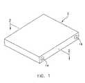
- FIG. 1is a perspective view of an evaporator formed in accordance with the present invention
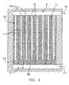
- FIG. 2is a perspective, transverse cross-sectional view of the evaporator shown in FIG. 1 ;
- FIG. 3is a plan view of the cross-section shown in FIG. 2 ;
- FIG. 4is a front elevational view of a typical semiconductor device burn-in-testing station
- FIG. 5is an exploded perspective view of a typical semiconductor device mounted for burn-in-testing, and positioned above an evaporator formed in accordance with the present invention
- FIG. 6is a schematic, partially cross-sectioned, representation of a cooling system utilizing an evaporator formed in accordance with the present invention
- FIG. 7is an enthalpy versus pressure diagram providing an operating curve for use in connection with the evaporator of the present invention.
- FIG. 8is an alternative embodiment of an evaporator formed in accordance with the present invention.
- an evaporator 2 formed in accordance with the present inventionincludes an inlet manifold 4 , an outlet manifold 6 , a plurality of blind passageways 11 , and a porous valve 13 .
- Evaporator 2is formed in an enclosure that is formed from a highly thermally conductive material, e.g., copper or its alloys, aluminum or its alloys, or steel.
- An enclosure for purposes of this descriptionwill usually mean a walled or otherwise inclosed, shut up, or encompassed void (or voids) that is separated from surrounding structures by a plurality of solid dividing structures, e.g., walls.
- An evaporator enclosure 2 of the type used in connection with the present inventionoften comprises a substantially flat aspect ratio so as to complement a variety of flat heat sources, e.g., a wide variety of semiconductor devices and packages.
- Inlet manifold 4 and outlet manifold 6often comprise substantially parallel blind bores that are located in spaced relation to one another within evaporator 2 .
- An inlet opening 14 in a side surface ( FIGS. 1 , 2 , and 3 ) or top surface ( FIG. 8 ) of evaporator 2is arranged in open flow communication with inlet manifold 4 and a condenser assembly 26 , via a coolant conduit 28 ( FIGS. 2 , 3 , and 7 ) and an outlet opening 16 is arranged in flow communication with outlet manifold 6 and condenser assembly 26 , via vapor conduit 29 .
- Each passageway 11is lined or covered with a capillary wick 32 formed on the interior surfaces of evaporator 2 that define each passageway 11 .
- Capillary wick 32most often comprises a sintered or brazed metal powder structure with interstices between the particles of powder.
- capillary wick 32may also other wicking structures, such as, grooves, screen, cables, adjacent layers of screening, and felt.
- capillary wick 32may comprise sintered copper powder, sintered aluminum-silicon-carbide (AlSiC) or copper-silicon-carbide (CuSiC) having an average thickness of about 0.1 mm to 1.0 mm.
- a coolant fluid 35saturates capillary wick 32 during operation of evaporator 2 , and may comprise any of the well known two-phase vaporizable liquids, e.g., water, alcohol, freon, etc.
- a porous valve 13is formed within evaporator 2 so as to create the blind end of each passageway 11 .
- Porous valve 13comprises a plug of poriferous material, e.g., a powdered metal meshwork, that is permeable to coolant fluid 35 , but at a substantially reduced rate as compared to an unobstructed portion of passageway 11 .
- porous valve 13forms a seeping barrier to liquid coolant fluid 35 and between inlet manifold 4 and the capillary wick that lines passageway 11 .
- porous valve 13may be formed from a sintered material, e.g., copper, with pores sized in a range from about 25 ⁇ m to about 150 ⁇ m, with pores sized in the range of 50 ⁇ m to about 80 ⁇ m being preferred for most applications using water for coolant fluid 35 .
- the length of porous valve 13may be set according to the flow rate through the valve that is needed to prevent drying out of capillary wick 32 .
- Porous valve 13is positioned within evaporator 2 so that an inlet surface 38 is in flow communication with inlet manifold 4 .
- Evaporator 2is normally arranged in intimate thermal engagement with a source of thermal energy, such as an integrated circuit chip or chips F, or an electronic device comprising such chips or other heat generating structures known in the art.
- a source of thermal energysuch as an integrated circuit chip or chips F, or an electronic device comprising such chips or other heat generating structures known in the art.
- Multiple evaporators 2may include external and/or internal features and structures to aid in the rapid vaporization of coolant fluid 35 .
- an externally applied thermally conductive coatingmay used to enhance heat transfer and spreading from the heat source throughout evaporator 2 .
- thermal management system 45In operation, evaporator 2 normally forms a portion of a thermal management system 45 ( FIG. 4 ).
- thermal management system 45also includes a condenser assembly 26 , a pump 50 , and a pressure control valve 52 .
- Condenser assembly 26comprises a chambered enclosure 55 having an inlet opening 57 arranged in flow communication with one or more evaporators 2 , via vapor conduit 29 , and an outlet opening 60 arranged in flow communication with each evaporator 2 through pump 50 and pressure valve 52 , via coolant conduit 28 .
- Condenser assembly 26acts as a heat exchanger transferring heat contained in vaporous coolant fluid 62 to the ambient surroundings or with a liquid cooled, secondary condenser 68 that is located within chambered enclosure 55 , and chilled by a flowing liquid or gas, e.g., chilled water or air, from a pumped source (not shown).
- a flowing liquid or gase.g., chilled water or air
- Pump 50is arranged in fluid communication between each evaporator 2 and condenser assembly 26 .
- Pump 50provides a continuous flow of liquid coolant 35 to the inlet manifold 4 of each evaporator 2 from condenser assembly 26 .
- Pressure control valve 52helps to maintain an optimum pressure level within inlet manifold 4 so as to produce a constant and continuous seepage of liquid coolant fluid 35 through porous valves 13 .
- FIG. 8provides a graphical representation of the preferred relationship between the seepage of liquid coolant fluid 35 through porous valves 13 as a function of coolant liquid pressure within inlet manifold 4 .
- each blind passageway 11 within evaporator 2acts as a driven-heat pipe with a porous valve 13 located at one end to maintain capillary wick 32 continuously saturated with coolant liquid 35 .
- thermal energyis absorbed by evaporator 2 from heat source F, e.g., a semiconductor chip, by evaporation of liquid coolant 35 (within those portions of capillary wick 32 that are adjacent to heat source F) to vaporous coolant 62 inside each blind passageway 11 .
- heat source Fe.g., a semiconductor chip
- capillary wick 32provides nucleation sites for bubble formation and retains coolant liquid 35 so that nearly pure vaporous coolant exits passageway 11 from open end 30 .
- Vaporous coolant 62with its absorbed heat load, is thermodynamically driven to each open end 30 due to a pressure difference created between heat source F and the heat sink formed by outlet manifold 6 .
- fresh liquid coolant 35seeps into each driven-heat pipe under a predetermined pressure head of liquid coolant provided in inlet manifold 4 by the action of pump 35 .
- Thiscauses liquid coolant 50 into each driven-heat pipe, via porous valve 13 , so as to further wet and thereby replenish capillary wick 32 and to replace the now vaporized coolant.
- the heat loadis rejected by vaporous coolant 62 to condenser assembly 26 , with consequent condensation of vaporous coolant 62 to liquid coolant 35 .
- pump 50forces condensed liquid coolant 35 to return to inlet manifold 4 .
Landscapes
- Engineering & Computer Science (AREA)
- General Engineering & Computer Science (AREA)
- Physics & Mathematics (AREA)
- Thermal Sciences (AREA)
- Mechanical Engineering (AREA)
- Life Sciences & Earth Sciences (AREA)
- Sustainable Development (AREA)
- Computer Hardware Design (AREA)
- Microelectronics & Electronic Packaging (AREA)
- General Physics & Mathematics (AREA)
- Environmental & Geological Engineering (AREA)
- Health & Medical Sciences (AREA)
- Toxicology (AREA)
- Cooling Or The Like Of Semiconductors Or Solid State Devices (AREA)
Abstract
Description
Claims (15)
Priority Applications (2)
| Application Number | Priority Date | Filing Date | Title |
|---|---|---|---|
| US10/930,018US7013956B2 (en) | 2003-09-02 | 2004-08-30 | Heat pipe evaporator with porous valve |
| US11/337,407US7143818B2 (en) | 2003-09-02 | 2006-01-23 | Heat pipe evaporator with porous valve |
Applications Claiming Priority (3)
| Application Number | Priority Date | Filing Date | Title |
|---|---|---|---|
| US49948303P | 2003-09-02 | 2003-09-02 | |
| US50212503P | 2003-09-11 | 2003-09-11 | |
| US10/930,018US7013956B2 (en) | 2003-09-02 | 2004-08-30 | Heat pipe evaporator with porous valve |
Related Child Applications (1)
| Application Number | Title | Priority Date | Filing Date |
|---|---|---|---|
| US11/337,407ContinuationUS7143818B2 (en) | 2003-09-02 | 2006-01-23 | Heat pipe evaporator with porous valve |
Publications (2)
| Publication Number | Publication Date |
|---|---|
| US20050067155A1 US20050067155A1 (en) | 2005-03-31 |
| US7013956B2true US7013956B2 (en) | 2006-03-21 |
Family
ID=34381958
Family Applications (2)
| Application Number | Title | Priority Date | Filing Date |
|---|---|---|---|
| US10/930,018Expired - LifetimeUS7013956B2 (en) | 2003-09-02 | 2004-08-30 | Heat pipe evaporator with porous valve |
| US11/337,407Expired - Fee RelatedUS7143818B2 (en) | 2003-09-02 | 2006-01-23 | Heat pipe evaporator with porous valve |
Family Applications After (1)
| Application Number | Title | Priority Date | Filing Date |
|---|---|---|---|
| US11/337,407Expired - Fee RelatedUS7143818B2 (en) | 2003-09-02 | 2006-01-23 | Heat pipe evaporator with porous valve |
Country Status (1)
| Country | Link |
|---|---|
| US (2) | US7013956B2 (en) |
Cited By (31)
| Publication number | Priority date | Publication date | Assignee | Title |
|---|---|---|---|---|
| US20050225943A1 (en)* | 2004-04-07 | 2005-10-13 | Delta Electronics, Inc. | Heat dissipation module |
| US20060002090A1 (en)* | 2004-05-28 | 2006-01-05 | Rhinol Tech Corp. | Heat sink modules for light and thin electronic equipment |
| US20060005953A1 (en)* | 2004-06-25 | 2006-01-12 | Foxconn Technology Co., Ltd | Liquid cooling device |
| US20060185827A1 (en)* | 2005-02-18 | 2006-08-24 | Bin-Juine Huang | Heat pipe cooling system and thermal connector thereof |
| US20070095507A1 (en)* | 2005-09-16 | 2007-05-03 | University Of Cincinnati | Silicon mems based two-phase heat transfer device |
| US20080179046A1 (en)* | 2007-01-31 | 2008-07-31 | Kabushiki Kaisha Toshiba | Water cooling apparatus |
| US20090008130A1 (en)* | 2004-09-02 | 2009-01-08 | Minhua Lu | Cooling of substrate using interposer channels |
| US20090288814A1 (en)* | 2008-05-20 | 2009-11-26 | The Boeing Company. | Mixed Carbon Foam/Metallic Heat Exchanger |
| US20090314472A1 (en)* | 2008-06-18 | 2009-12-24 | Chul Ju Kim | Evaporator For Loop Heat Pipe System |
| US20100132404A1 (en)* | 2008-12-03 | 2010-06-03 | Progressive Cooling Solutions, Inc. | Bonds and method for forming bonds for a two-phase cooling apparatus |
| CN102022863A (en)* | 2011-01-24 | 2011-04-20 | 重庆大学 | Air-conditioning heat exchanger at tail end of parallel flow capillary imbibition core plate |
| CN102157468A (en)* | 2011-03-17 | 2011-08-17 | 北京芯铠电子散热技术有限责任公司 | High-power loop heat pipe radiator and manufacturing method thereof |
| US20110297354A1 (en)* | 2006-12-12 | 2011-12-08 | Regents Of The University Of Minnesota | System and method that dissipate heat from an electronic device |
| US20120043060A1 (en)* | 2010-08-20 | 2012-02-23 | Foxconn Technology Co., Ltd. | Loop heat pipe |
| EP2439821A1 (en) | 2010-10-07 | 2012-04-11 | Raytheon Company | Method and system for cooling a fiber laser or amplifier |
| US8188595B2 (en) | 2008-08-13 | 2012-05-29 | Progressive Cooling Solutions, Inc. | Two-phase cooling for light-emitting devices |
| US20130039819A1 (en)* | 2011-08-09 | 2013-02-14 | Asia Vital Components Co., Ltd. | Vapor chamber and method of manufacturing same |
| US20130258594A1 (en)* | 2012-03-28 | 2013-10-03 | Abb Research Ltd | Heat exchanger for traction converters |
| WO2013172988A1 (en)* | 2012-05-16 | 2013-11-21 | The Government Of The United States Of America, As Represented By The Secretary Of The Navy | Temperature- actuated capillary valve for loop heat pipe system |
| US8893513B2 (en) | 2012-05-07 | 2014-11-25 | Phononic Device, Inc. | Thermoelectric heat exchanger component including protective heat spreading lid and optimal thermal interface resistance |
| US8991194B2 (en) | 2012-05-07 | 2015-03-31 | Phononic Devices, Inc. | Parallel thermoelectric heat exchange systems |
| US9009971B2 (en) | 2012-09-26 | 2015-04-21 | International Business Machines Corporation | Wicking and coupling element(s) facilitating evaporative cooling of component(s) |
| US9279626B2 (en)* | 2012-01-23 | 2016-03-08 | Honeywell International Inc. | Plate-fin heat exchanger with a porous blocker bar |
| US20160116226A1 (en)* | 2013-05-29 | 2016-04-28 | Euro Heat Pipes | Two-phase heat transfer device |
| US20160366789A1 (en)* | 2015-03-03 | 2016-12-15 | International Business Machines Corporation | Active control for two-phase cooling |
| US9593871B2 (en) | 2014-07-21 | 2017-03-14 | Phononic Devices, Inc. | Systems and methods for operating a thermoelectric module to increase efficiency |
| US20180249596A1 (en)* | 2015-09-14 | 2018-08-30 | Mitsubishi Electric Corporation | Cooler, power conversion apparatus, and cooling system |
| US10458683B2 (en) | 2014-07-21 | 2019-10-29 | Phononic, Inc. | Systems and methods for mitigating heat rejection limitations of a thermoelectric module |
| US11326836B1 (en)* | 2020-10-22 | 2022-05-10 | Asia Vital Components Co., Ltd. | Vapor/liquid condensation system |
| US11340023B1 (en)* | 2017-03-24 | 2022-05-24 | Triad National Security, Llc | Counter gravity heat pipe techniques |
| US20230221080A1 (en)* | 2022-01-10 | 2023-07-13 | Long Victory Instruments Co., Ltd. | Liquid vapor composite heat dissipation system |
Families Citing this family (32)
| Publication number | Priority date | Publication date | Assignee | Title |
|---|---|---|---|---|
| JP2005268658A (en)* | 2004-03-19 | 2005-09-29 | Denso Corp | Boiling cooler |
| TW200724010A (en)* | 2005-12-02 | 2007-06-16 | Cooler Master Co Ltd | Water-cooling head and the manufacturing method |
| TWI285252B (en)* | 2006-02-14 | 2007-08-11 | Yeh Chiang Technology Corp | Loop type heat conduction device |
| JP2008057820A (en)* | 2006-08-30 | 2008-03-13 | Denso Corp | Heat exchanger |
| US20080078530A1 (en)* | 2006-10-02 | 2008-04-03 | Foxconn Technology Co., Ltd. | Loop heat pipe with flexible artery mesh |
| US20080105413A1 (en)* | 2006-10-16 | 2008-05-08 | Yu-Huang Peng | Manufacturing Method of Water Block |
| TWM309700U (en)* | 2006-10-16 | 2007-04-11 | Quanta Comp Inc | Thermal module |
| JP2008159762A (en)* | 2006-12-22 | 2008-07-10 | Espec Corp | Heating medium supply device and temperature control apparatus |
| US8100170B2 (en)* | 2007-08-01 | 2012-01-24 | Advanced Thermal Device Inc. | Evaporator, loop heat pipe module and heat generating apparatus |
| CN102065984B (en)* | 2008-05-05 | 2014-09-03 | 康奈尔大学 | High performance wick |
| US8596341B2 (en)* | 2008-06-05 | 2013-12-03 | Battelle Memorial Institute | Enhanced two phase flow in heat transfer systems |
| CN101478868B (en)* | 2009-01-23 | 2012-06-13 | 北京奇宏科技研发中心有限公司 | Heat radiating device |
| TW201038900A (en)* | 2009-04-21 | 2010-11-01 | Yeh Chiang Technology Corp | Sintered heat pipe |
| AU2010291608A1 (en)* | 2009-09-02 | 2012-04-05 | Invensor Gmbh | Surface feeding and distribution of a refrigerant for a heat exchanger in sorption machines |
| CN102042776A (en)* | 2009-10-16 | 2011-05-04 | 富准精密工业(深圳)有限公司 | Loop heat pipe |
| US20120255716A1 (en)* | 2011-04-07 | 2012-10-11 | Wu Wen-Yuan | Heat dissipation device and manufacturing method thereof |
| US20150101784A1 (en)* | 2013-10-15 | 2015-04-16 | Hao Pai | Heat pipe with ultra-thin flat wick structure |
| US20150101783A1 (en)* | 2013-10-15 | 2015-04-16 | Hao Pai | Thermal conductor with ultra-thin flat wick structure |
| JP6372159B2 (en)* | 2014-05-19 | 2018-08-15 | 富士通株式会社 | Evaporator, cooling device and electronic equipment |
| US9560790B2 (en)* | 2015-05-13 | 2017-01-31 | Toyota Motor Engineering & Manufacturing North America, Inc. | Power electronics cooling system with two-phase cooler |
| US10634397B2 (en) | 2015-09-17 | 2020-04-28 | Purdue Research Foundation | Devices, systems, and methods for the rapid transient cooling of pulsed heat sources |
| US12255123B2 (en) | 2015-09-30 | 2025-03-18 | Microfabrica Inc. | Micro heat transfer arrays, micro cold plates, and thermal management systems for semiconductor devices, and methods for using and making such arrays, plates, and systems |
| CN106766404B (en)* | 2017-01-10 | 2018-09-28 | 中国科学院理化技术研究所 | Micro-channel condenser |
| US20180209745A1 (en)* | 2017-01-26 | 2018-07-26 | Asia Vital Components Co., Ltd. | Loop heat pipe structure |
| TWI650520B (en)* | 2017-08-02 | 2019-02-11 | 萬在工業股份有限公司 | Phase change evaporator and phase change heat sink |
| TWI645155B (en)* | 2018-02-27 | 2018-12-21 | 雙鴻科技股份有限公司 | Heat sink device |
| SG10201904782SA (en)* | 2019-05-27 | 2020-12-30 | Aem Singapore Pte Ltd | Cold plate and a method of manufacture thereof |
| CN113203588B (en)* | 2021-04-26 | 2022-04-01 | 浙江大学 | Multi-stage gravity type self-flowing liquid working medium heat management performance testing system and method |
| CN114777542B (en)* | 2021-11-03 | 2023-08-22 | 山东大学 | Manifold shell-and-tube heat exchanger |
| TWI815257B (en)* | 2021-12-23 | 2023-09-11 | 長聖儀器股份有限公司 | Composite liquid-vapor phase conversion radiator with liquid inlet and vapor outlet |
| WO2024205910A1 (en)* | 2023-03-30 | 2024-10-03 | Water Reuse Technology, Inc. | Rotating evaporator device for liquid distillation or concentration |
| CN118310346B (en)* | 2024-05-14 | 2024-11-15 | 北京水木启华科技有限公司 | A manifold evaporator double-circuit loop heat pipe |
Citations (50)
| Publication number | Priority date | Publication date | Assignee | Title |
|---|---|---|---|---|
| US3543839A (en)* | 1969-05-14 | 1970-12-01 | Trw Inc | Multi-chamber controllable heat pipe |
| US4037830A (en) | 1976-09-07 | 1977-07-26 | International Business Machines Corporation | Wafer handler |
| US4213698A (en) | 1978-12-01 | 1980-07-22 | Bell Telephone Laboratories, Incorporated | Apparatus and method for holding and planarizing thin workpieces |
| USRE31053E (en) | 1978-01-23 | 1982-10-12 | Bell Telephone Laboratories, Incorporated | Apparatus and method for holding and planarizing thin workpieces |
| US4551192A (en) | 1983-06-30 | 1985-11-05 | International Business Machines Corporation | Electrostatic or vacuum pinchuck formed with microcircuit lithography |
| US4609037A (en) | 1985-10-09 | 1986-09-02 | Tencor Instruments | Apparatus for heating and cooling articles |
| US4784213A (en) | 1986-04-08 | 1988-11-15 | Temptronic Corporation | Mixing valve air source |
| US5001423A (en) | 1990-01-24 | 1991-03-19 | International Business Machines Corporation | Dry interface thermal chuck temperature control system for semiconductor wafer testing |
| US5084671A (en) | 1987-09-02 | 1992-01-28 | Tokyo Electron Limited | Electric probing-test machine having a cooling system |
| US5123982A (en)* | 1990-06-29 | 1992-06-23 | The United States Of American As Represented By The United States Department Of Energy | Process of making cryogenically cooled high thermal performance crystal optics |
| US5127471A (en)* | 1991-07-26 | 1992-07-07 | Weislogel Mark M | Pulse thermal energy transport/storage system |
| US5205353A (en)* | 1989-11-30 | 1993-04-27 | Akzo N.V. | Heat exchanging member |
| US5382311A (en) | 1992-12-17 | 1995-01-17 | Tokyo Electron Limited | Stage having electrostatic chuck and plasma processing apparatus using same |
| US5383971A (en) | 1990-10-12 | 1995-01-24 | Genus, Inc. | Differential pressure CVD chuck |
| US5435379A (en) | 1992-08-14 | 1995-07-25 | Texas Instruments Incorporated | Method and apparatus for low-temperature semiconductor processing |
| US5458687A (en) | 1992-11-20 | 1995-10-17 | Hitachi, Ltd. | Method of and apparatus for securing and cooling/heating a wafer |
| US5460684A (en) | 1992-12-04 | 1995-10-24 | Tokyo Electron Limited | Stage having electrostatic chuck and plasma processing apparatus using same |
| US5474877A (en) | 1994-02-24 | 1995-12-12 | Nec Corporation | Method for developing a resist pattern |
| US5478609A (en) | 1992-07-23 | 1995-12-26 | Canon Kabushiki Kaisha | Substrate heating mechanism |
| US5534073A (en) | 1992-09-07 | 1996-07-09 | Mitsubishi Denki Kabushiki Kaisha | Semiconductor producing apparatus comprising wafer vacuum chucking device |
| US5588827A (en) | 1993-12-17 | 1996-12-31 | Brooks Automation Inc. | Passive gas substrate thermal conditioning apparatus and method |
| US5610529A (en) | 1995-04-28 | 1997-03-11 | Cascade Microtech, Inc. | Probe station having conductive coating added to thermal chuck insulator |
| US5663653A (en) | 1992-06-11 | 1997-09-02 | Cascade Microtech, Inc. | Wafer probe station for low-current measurements |
| US5721090A (en) | 1994-09-22 | 1998-02-24 | Tokyo Electron Limited | Method of etching a substrate |
| US5725049A (en)* | 1995-10-31 | 1998-03-10 | The United States Of America As Represented By The Administrator Of The National Aeronautics And Space Administration | Capillary pumped loop body heat exchanger |
| US5730803A (en) | 1996-02-23 | 1998-03-24 | Applied Materials, Inc. | Apparatus and method for transferring heat from a hot electrostatic chuck to an underlying cold body |
| US5738165A (en) | 1993-05-07 | 1998-04-14 | Nikon Corporation | Substrate holding apparatus |
| US5762714A (en) | 1994-10-18 | 1998-06-09 | Applied Materials, Inc. | Plasma guard for chamber equipped with electrostatic chuck |
| US5820723A (en) | 1996-06-05 | 1998-10-13 | Lam Research Corporation | Universal vacuum chamber including equipment modules such as a plasma generating source, vacuum pumping arrangement and/or cantilevered substrate support |
| US5830808A (en) | 1993-10-29 | 1998-11-03 | Applied Materials, Inc. | Plasma reactor with magnet for protecting an electroacoustic chuck from the plasma |
| US5885353A (en) | 1996-06-21 | 1999-03-23 | Micron Technology, Inc. | Thermal conditioning apparatus |
| US5904776A (en) | 1996-04-26 | 1999-05-18 | Applied Materials, Inc. | Conduits for flow of heat transfer fluid to the surface of an electrostatic chuck |
| US5904779A (en) | 1996-12-19 | 1999-05-18 | Lam Research Corporation | Wafer electrical discharge control by wafer lifter system |
| US5958140A (en) | 1995-07-27 | 1999-09-28 | Tokyo Electron Limited | One-by-one type heat-processing apparatus |
| US6032724A (en) | 1996-10-29 | 2000-03-07 | Tokyo Electron Limited | Temperature control apparatus for sample susceptor |
| US6037793A (en) | 1997-01-30 | 2000-03-14 | Tokyo Electron Limited | Inspecting method and apparatus for semiconductor integrated circuit |
| US6073681A (en) | 1997-12-31 | 2000-06-13 | Temptronic Corporation | Workpiece chuck |
| US6227288B1 (en)* | 2000-05-01 | 2001-05-08 | The United States Of America As Represented By The Secretary Of The Air Force | Multifunctional capillary system for loop heat pipe statement of government interest |
| US6245202B1 (en) | 1996-04-12 | 2001-06-12 | Hitachi, Ltd. | Plasma treatment device |
| US6313649B2 (en) | 1992-06-11 | 2001-11-06 | Cascade Microtech, Inc. | Wafer probe station having environment control enclosure |
| US6394797B1 (en) | 1997-04-02 | 2002-05-28 | Hitachi, Ltd. | Substrate temperature control system and method for controlling temperature of substrate |
| US6450132B1 (en)* | 2000-02-10 | 2002-09-17 | Mitsubishi Denki Kabushiki Kaisha | Loop type heat pipe |
| US6471913B1 (en) | 2000-02-09 | 2002-10-29 | Semitool, Inc. | Method and apparatus for processing a microelectronic workpiece including an apparatus and method for executing a processing step at an elevated temperature |
| US20020157813A1 (en)* | 2001-04-28 | 2002-10-31 | Samsung Electronics Co., Ltd. | Flat evaporator |
| US6564860B1 (en)* | 2000-05-16 | 2003-05-20 | Swales Aerospace | Evaporator employing a liquid superheat tolerant wick |
| US20030106671A1 (en)* | 2001-04-27 | 2003-06-12 | Samsung Electronics Co., Ltd. | Flat evaporator |
| US6583638B2 (en) | 1999-01-26 | 2003-06-24 | Trio-Tech International | Temperature-controlled semiconductor wafer chuck system |
| US6615912B2 (en)* | 2001-06-20 | 2003-09-09 | Thermal Corp. | Porous vapor valve for improved loop thermosiphon performance |
| US6771086B2 (en) | 2002-02-19 | 2004-08-03 | Lucas/Signatone Corporation | Semiconductor wafer electrical testing with a mobile chiller plate for rapid and precise test temperature control |
| US20040206480A1 (en)* | 2001-08-09 | 2004-10-21 | Maydanik Yury Folyevich | Evaporation chamber for a loop heat pipe |
Family Cites Families (18)
| Publication number | Priority date | Publication date | Assignee | Title |
|---|---|---|---|---|
| US3404730A (en)* | 1966-12-02 | 1968-10-08 | Hughes Aircraft Co | Temperature control arrangement |
| US4524587A (en)* | 1967-01-10 | 1985-06-25 | Kantor Frederick W | Rotary thermodynamic apparatus and method |
| US3414050A (en)* | 1967-04-11 | 1968-12-03 | Navy Usa | Heat pipe control apparatus |
| US4201263A (en)* | 1978-09-19 | 1980-05-06 | Anderson James H | Refrigerant evaporator |
| GB2084308B (en)* | 1980-07-14 | 1983-11-30 | Cryoplants Ltd | Revapourising liquefied gas |
| US4441548A (en)* | 1981-12-28 | 1984-04-10 | The Boeing Company | High heat transport capacity heat pipe |
| US4611654A (en)* | 1985-01-23 | 1986-09-16 | Buchsel Christian K E | Passive system for heat transfer |
| US4765396A (en)* | 1986-12-16 | 1988-08-23 | The United States Of America As Represented By The Administrator Of The National Aeronautics And Space Administration | Polymeric heat pipe wick |
| JP2859927B2 (en)* | 1990-05-16 | 1999-02-24 | 株式会社東芝 | Cooling device and temperature control device |
| US5076352A (en)* | 1991-02-08 | 1991-12-31 | Thermacore, Inc. | High permeability heat pipe wick structure |
| US5103897A (en)* | 1991-06-05 | 1992-04-14 | Martin Marietta Corporation | Flowrate controller for hybrid capillary/mechanical two-phase thermal loops |
| FR2702831B1 (en)* | 1993-03-17 | 1995-05-24 | Faudat | Method and device for cooling the enclosure of a heat exchanger. |
| FR2723187B1 (en)* | 1994-07-29 | 1996-09-27 | Centre Nat Etd Spatiales | ENERGY TRANSFER SYSTEM BETWEEN A HOT SOURCE AND A COLD SOURCE |
| SE9500944L (en)* | 1995-03-17 | 1996-05-28 | Ericsson Telefon Ab L M | Cooling system for electronics |
| US5566751A (en)* | 1995-05-22 | 1996-10-22 | Thermacore, Inc. | Vented vapor source |
| US6058712A (en)* | 1996-07-12 | 2000-05-09 | Thermotek, Inc. | Hybrid air conditioning system and a method therefor |
| JP3450148B2 (en)* | 1997-03-07 | 2003-09-22 | 三菱電機株式会社 | Loop type heat pipe |
| US5884693A (en)* | 1997-12-31 | 1999-03-23 | Dsc Telecom L.P. | Integral heat pipe enclosure |
- 2004
- 2004-08-30USUS10/930,018patent/US7013956B2/ennot_activeExpired - Lifetime
- 2006
- 2006-01-23USUS11/337,407patent/US7143818B2/ennot_activeExpired - Fee Related
Patent Citations (50)
| Publication number | Priority date | Publication date | Assignee | Title |
|---|---|---|---|---|
| US3543839A (en)* | 1969-05-14 | 1970-12-01 | Trw Inc | Multi-chamber controllable heat pipe |
| US4037830A (en) | 1976-09-07 | 1977-07-26 | International Business Machines Corporation | Wafer handler |
| USRE31053E (en) | 1978-01-23 | 1982-10-12 | Bell Telephone Laboratories, Incorporated | Apparatus and method for holding and planarizing thin workpieces |
| US4213698A (en) | 1978-12-01 | 1980-07-22 | Bell Telephone Laboratories, Incorporated | Apparatus and method for holding and planarizing thin workpieces |
| US4551192A (en) | 1983-06-30 | 1985-11-05 | International Business Machines Corporation | Electrostatic or vacuum pinchuck formed with microcircuit lithography |
| US4609037A (en) | 1985-10-09 | 1986-09-02 | Tencor Instruments | Apparatus for heating and cooling articles |
| US4784213A (en) | 1986-04-08 | 1988-11-15 | Temptronic Corporation | Mixing valve air source |
| US5084671A (en) | 1987-09-02 | 1992-01-28 | Tokyo Electron Limited | Electric probing-test machine having a cooling system |
| US5205353A (en)* | 1989-11-30 | 1993-04-27 | Akzo N.V. | Heat exchanging member |
| US5001423A (en) | 1990-01-24 | 1991-03-19 | International Business Machines Corporation | Dry interface thermal chuck temperature control system for semiconductor wafer testing |
| US5123982A (en)* | 1990-06-29 | 1992-06-23 | The United States Of American As Represented By The United States Department Of Energy | Process of making cryogenically cooled high thermal performance crystal optics |
| US5383971A (en) | 1990-10-12 | 1995-01-24 | Genus, Inc. | Differential pressure CVD chuck |
| US5127471A (en)* | 1991-07-26 | 1992-07-07 | Weislogel Mark M | Pulse thermal energy transport/storage system |
| US6313649B2 (en) | 1992-06-11 | 2001-11-06 | Cascade Microtech, Inc. | Wafer probe station having environment control enclosure |
| US5663653A (en) | 1992-06-11 | 1997-09-02 | Cascade Microtech, Inc. | Wafer probe station for low-current measurements |
| US5478609A (en) | 1992-07-23 | 1995-12-26 | Canon Kabushiki Kaisha | Substrate heating mechanism |
| US5435379A (en) | 1992-08-14 | 1995-07-25 | Texas Instruments Incorporated | Method and apparatus for low-temperature semiconductor processing |
| US5534073A (en) | 1992-09-07 | 1996-07-09 | Mitsubishi Denki Kabushiki Kaisha | Semiconductor producing apparatus comprising wafer vacuum chucking device |
| US5458687A (en) | 1992-11-20 | 1995-10-17 | Hitachi, Ltd. | Method of and apparatus for securing and cooling/heating a wafer |
| US5460684A (en) | 1992-12-04 | 1995-10-24 | Tokyo Electron Limited | Stage having electrostatic chuck and plasma processing apparatus using same |
| US5382311A (en) | 1992-12-17 | 1995-01-17 | Tokyo Electron Limited | Stage having electrostatic chuck and plasma processing apparatus using same |
| US5738165A (en) | 1993-05-07 | 1998-04-14 | Nikon Corporation | Substrate holding apparatus |
| US5830808A (en) | 1993-10-29 | 1998-11-03 | Applied Materials, Inc. | Plasma reactor with magnet for protecting an electroacoustic chuck from the plasma |
| US5588827A (en) | 1993-12-17 | 1996-12-31 | Brooks Automation Inc. | Passive gas substrate thermal conditioning apparatus and method |
| US5474877A (en) | 1994-02-24 | 1995-12-12 | Nec Corporation | Method for developing a resist pattern |
| US5721090A (en) | 1994-09-22 | 1998-02-24 | Tokyo Electron Limited | Method of etching a substrate |
| US5762714A (en) | 1994-10-18 | 1998-06-09 | Applied Materials, Inc. | Plasma guard for chamber equipped with electrostatic chuck |
| US5610529A (en) | 1995-04-28 | 1997-03-11 | Cascade Microtech, Inc. | Probe station having conductive coating added to thermal chuck insulator |
| US5958140A (en) | 1995-07-27 | 1999-09-28 | Tokyo Electron Limited | One-by-one type heat-processing apparatus |
| US5725049A (en)* | 1995-10-31 | 1998-03-10 | The United States Of America As Represented By The Administrator Of The National Aeronautics And Space Administration | Capillary pumped loop body heat exchanger |
| US5730803A (en) | 1996-02-23 | 1998-03-24 | Applied Materials, Inc. | Apparatus and method for transferring heat from a hot electrostatic chuck to an underlying cold body |
| US6245202B1 (en) | 1996-04-12 | 2001-06-12 | Hitachi, Ltd. | Plasma treatment device |
| US5904776A (en) | 1996-04-26 | 1999-05-18 | Applied Materials, Inc. | Conduits for flow of heat transfer fluid to the surface of an electrostatic chuck |
| US5820723A (en) | 1996-06-05 | 1998-10-13 | Lam Research Corporation | Universal vacuum chamber including equipment modules such as a plasma generating source, vacuum pumping arrangement and/or cantilevered substrate support |
| US5885353A (en) | 1996-06-21 | 1999-03-23 | Micron Technology, Inc. | Thermal conditioning apparatus |
| US6032724A (en) | 1996-10-29 | 2000-03-07 | Tokyo Electron Limited | Temperature control apparatus for sample susceptor |
| US5904779A (en) | 1996-12-19 | 1999-05-18 | Lam Research Corporation | Wafer electrical discharge control by wafer lifter system |
| US6037793A (en) | 1997-01-30 | 2000-03-14 | Tokyo Electron Limited | Inspecting method and apparatus for semiconductor integrated circuit |
| US6394797B1 (en) | 1997-04-02 | 2002-05-28 | Hitachi, Ltd. | Substrate temperature control system and method for controlling temperature of substrate |
| US6073681A (en) | 1997-12-31 | 2000-06-13 | Temptronic Corporation | Workpiece chuck |
| US6583638B2 (en) | 1999-01-26 | 2003-06-24 | Trio-Tech International | Temperature-controlled semiconductor wafer chuck system |
| US6471913B1 (en) | 2000-02-09 | 2002-10-29 | Semitool, Inc. | Method and apparatus for processing a microelectronic workpiece including an apparatus and method for executing a processing step at an elevated temperature |
| US6450132B1 (en)* | 2000-02-10 | 2002-09-17 | Mitsubishi Denki Kabushiki Kaisha | Loop type heat pipe |
| US6227288B1 (en)* | 2000-05-01 | 2001-05-08 | The United States Of America As Represented By The Secretary Of The Air Force | Multifunctional capillary system for loop heat pipe statement of government interest |
| US6564860B1 (en)* | 2000-05-16 | 2003-05-20 | Swales Aerospace | Evaporator employing a liquid superheat tolerant wick |
| US20030106671A1 (en)* | 2001-04-27 | 2003-06-12 | Samsung Electronics Co., Ltd. | Flat evaporator |
| US20020157813A1 (en)* | 2001-04-28 | 2002-10-31 | Samsung Electronics Co., Ltd. | Flat evaporator |
| US6615912B2 (en)* | 2001-06-20 | 2003-09-09 | Thermal Corp. | Porous vapor valve for improved loop thermosiphon performance |
| US20040206480A1 (en)* | 2001-08-09 | 2004-10-21 | Maydanik Yury Folyevich | Evaporation chamber for a loop heat pipe |
| US6771086B2 (en) | 2002-02-19 | 2004-08-03 | Lucas/Signatone Corporation | Semiconductor wafer electrical testing with a mobile chiller plate for rapid and precise test temperature control |
Cited By (66)
| Publication number | Priority date | Publication date | Assignee | Title |
|---|---|---|---|---|
| US20050225943A1 (en)* | 2004-04-07 | 2005-10-13 | Delta Electronics, Inc. | Heat dissipation module |
| US7277285B2 (en)* | 2004-04-07 | 2007-10-02 | Delta Electronics, Inc. | Heat dissipation module |
| US20060002090A1 (en)* | 2004-05-28 | 2006-01-05 | Rhinol Tech Corp. | Heat sink modules for light and thin electronic equipment |
| US7262966B2 (en)* | 2004-05-28 | 2007-08-28 | Rhinol Tech Corp. | Heat sink modules for light and thin electronic equipment |
| US20060005953A1 (en)* | 2004-06-25 | 2006-01-12 | Foxconn Technology Co., Ltd | Liquid cooling device |
| US20090008130A1 (en)* | 2004-09-02 | 2009-01-08 | Minhua Lu | Cooling of substrate using interposer channels |
| US8110746B2 (en) | 2004-09-02 | 2012-02-07 | International Business Machines Corporation | Cooling of substrate using interposer channels |
| US20060185827A1 (en)* | 2005-02-18 | 2006-08-24 | Bin-Juine Huang | Heat pipe cooling system and thermal connector thereof |
| US7819174B2 (en)* | 2005-02-18 | 2010-10-26 | Advanced Thermal Device Inc. | Heat pipe cooling system and thermal connector thereof |
| US20080115912A1 (en)* | 2005-09-16 | 2008-05-22 | Henderson H Thurman | Semiconductor-based porous structure |
| US20070095507A1 (en)* | 2005-09-16 | 2007-05-03 | University Of Cincinnati | Silicon mems based two-phase heat transfer device |
| US20080115913A1 (en)* | 2005-09-16 | 2008-05-22 | Henderson H Thurman | Method of fabricating semiconductor-based porous structure |
| US20080110598A1 (en)* | 2005-09-16 | 2008-05-15 | Progressive Cooling Solutions, Inc. | System and method of a heat transfer system and a condensor |
| US7692926B2 (en)* | 2005-09-16 | 2010-04-06 | Progressive Cooling Solutions, Inc. | Integrated thermal systems |
| US7705342B2 (en) | 2005-09-16 | 2010-04-27 | University Of Cincinnati | Porous semiconductor-based evaporator having porous and non-porous regions, the porous regions having through-holes |
| US7723760B2 (en) | 2005-09-16 | 2010-05-25 | University Of Cincinnati | Semiconductor-based porous structure enabled by capillary force |
| US7723845B2 (en) | 2005-09-16 | 2010-05-25 | University Of Cincinnati | System and method of a heat transfer system with an evaporator and a condenser |
| US20080128898A1 (en)* | 2005-09-16 | 2008-06-05 | Progressive Cooling Solutions, Inc. | Integrated thermal systems |
| US20110297354A1 (en)* | 2006-12-12 | 2011-12-08 | Regents Of The University Of Minnesota | System and method that dissipate heat from an electronic device |
| US8360138B2 (en)* | 2006-12-12 | 2013-01-29 | Honeywell International Inc. | System and method that dissipate heat from an electronic device |
| US20080179046A1 (en)* | 2007-01-31 | 2008-07-31 | Kabushiki Kaisha Toshiba | Water cooling apparatus |
| US20090288814A1 (en)* | 2008-05-20 | 2009-11-26 | The Boeing Company. | Mixed Carbon Foam/Metallic Heat Exchanger |
| US20090314472A1 (en)* | 2008-06-18 | 2009-12-24 | Chul Ju Kim | Evaporator For Loop Heat Pipe System |
| US8188595B2 (en) | 2008-08-13 | 2012-05-29 | Progressive Cooling Solutions, Inc. | Two-phase cooling for light-emitting devices |
| US20100132404A1 (en)* | 2008-12-03 | 2010-06-03 | Progressive Cooling Solutions, Inc. | Bonds and method for forming bonds for a two-phase cooling apparatus |
| US8622118B2 (en)* | 2010-08-20 | 2014-01-07 | Fu Zhun Precision Industry (Shen Zhen) Co., Ltd. | Loop heat pipe |
| US20120043060A1 (en)* | 2010-08-20 | 2012-02-23 | Foxconn Technology Co., Ltd. | Loop heat pipe |
| EP2439821A1 (en) | 2010-10-07 | 2012-04-11 | Raytheon Company | Method and system for cooling a fiber laser or amplifier |
| US8467426B2 (en) | 2010-10-07 | 2013-06-18 | Raytheon Company | Method and apparatus for cooling a fiber laser or amplifier |
| CN102022863A (en)* | 2011-01-24 | 2011-04-20 | 重庆大学 | Air-conditioning heat exchanger at tail end of parallel flow capillary imbibition core plate |
| CN102157468A (en)* | 2011-03-17 | 2011-08-17 | 北京芯铠电子散热技术有限责任公司 | High-power loop heat pipe radiator and manufacturing method thereof |
| CN102157468B (en)* | 2011-03-17 | 2013-01-16 | 北京芯铠电子散热技术有限责任公司 | High-power loop heat pipe radiator and manufacturing method thereof |
| US20130039819A1 (en)* | 2011-08-09 | 2013-02-14 | Asia Vital Components Co., Ltd. | Vapor chamber and method of manufacturing same |
| US20140165402A1 (en)* | 2011-08-09 | 2014-06-19 | Asia Vital Components Co., Ltd. | Vapor chamber and method of manufacturing same |
| US9279626B2 (en)* | 2012-01-23 | 2016-03-08 | Honeywell International Inc. | Plate-fin heat exchanger with a porous blocker bar |
| US20130258594A1 (en)* | 2012-03-28 | 2013-10-03 | Abb Research Ltd | Heat exchanger for traction converters |
| US9097467B2 (en)* | 2012-03-28 | 2015-08-04 | Abb Research Ltd | Heat exchanger for traction converters |
| US9310111B2 (en) | 2012-05-07 | 2016-04-12 | Phononic Devices, Inc. | Systems and methods to mitigate heat leak back in a thermoelectric refrigeration system |
| US8991194B2 (en) | 2012-05-07 | 2015-03-31 | Phononic Devices, Inc. | Parallel thermoelectric heat exchange systems |
| US8893513B2 (en) | 2012-05-07 | 2014-11-25 | Phononic Device, Inc. | Thermoelectric heat exchanger component including protective heat spreading lid and optimal thermal interface resistance |
| US10012417B2 (en) | 2012-05-07 | 2018-07-03 | Phononic, Inc. | Thermoelectric refrigeration system control scheme for high efficiency performance |
| US9103572B2 (en) | 2012-05-07 | 2015-08-11 | Phononic Devices, Inc. | Physically separated hot side and cold side heat sinks in a thermoelectric refrigeration system |
| US9341394B2 (en) | 2012-05-07 | 2016-05-17 | Phononic Devices, Inc. | Thermoelectric heat exchange system comprising cascaded cold side heat sinks |
| US9234682B2 (en) | 2012-05-07 | 2016-01-12 | Phononic Devices, Inc. | Two-phase heat exchanger mounting |
| US10704839B2 (en)* | 2012-05-16 | 2020-07-07 | The Government Of The United States Of America, As Represented By The Secretary Of The Navy | Temperature actuated capillary valve for loop heat pipe system |
| US9146059B2 (en) | 2012-05-16 | 2015-09-29 | The United States Of America, As Represented By The Secretary Of The Navy | Temperature actuated capillary valve for loop heat pipe system |
| US10030914B2 (en) | 2012-05-16 | 2018-07-24 | The United States Of America, As Represented By The Secretary Of The Navy | Temperature actuated capillary valve for loop heat pipe system |
| WO2013172988A1 (en)* | 2012-05-16 | 2013-11-21 | The Government Of The United States Of America, As Represented By The Secretary Of The Navy | Temperature- actuated capillary valve for loop heat pipe system |
| US9009971B2 (en) | 2012-09-26 | 2015-04-21 | International Business Machines Corporation | Wicking and coupling element(s) facilitating evaporative cooling of component(s) |
| US9095942B2 (en) | 2012-09-26 | 2015-08-04 | International Business Machines Corporation | Wicking and coupling element(s) facilitating evaporative cooling of component(s) |
| US10209008B2 (en)* | 2013-05-29 | 2019-02-19 | Euro Heat Pipes | Two-phase heat transfer device |
| US20160116226A1 (en)* | 2013-05-29 | 2016-04-28 | Euro Heat Pipes | Two-phase heat transfer device |
| US9593871B2 (en) | 2014-07-21 | 2017-03-14 | Phononic Devices, Inc. | Systems and methods for operating a thermoelectric module to increase efficiency |
| US10458683B2 (en) | 2014-07-21 | 2019-10-29 | Phononic, Inc. | Systems and methods for mitigating heat rejection limitations of a thermoelectric module |
| US10231359B2 (en)* | 2015-03-03 | 2019-03-12 | International Business Machines Corporation | Active control for two-phase cooling |
| US9986662B2 (en) | 2015-03-03 | 2018-05-29 | International Business Machines Corporation | Active control for two-phase cooling |
| US20160366789A1 (en)* | 2015-03-03 | 2016-12-15 | International Business Machines Corporation | Active control for two-phase cooling |
| US11464137B2 (en) | 2015-03-03 | 2022-10-04 | International Business Machines Corporation | Active control for two-phase cooling |
| US20180249596A1 (en)* | 2015-09-14 | 2018-08-30 | Mitsubishi Electric Corporation | Cooler, power conversion apparatus, and cooling system |
| US10729040B2 (en)* | 2015-09-14 | 2020-07-28 | Mitsubishi Electric Corporation | Cooler, power conversion apparatus, and cooling system |
| US11340023B1 (en)* | 2017-03-24 | 2022-05-24 | Triad National Security, Llc | Counter gravity heat pipe techniques |
| US11879689B1 (en) | 2017-03-24 | 2024-01-23 | Triad National Security, Llc | Counter gravity heat pipe techniques |
| US11326836B1 (en)* | 2020-10-22 | 2022-05-10 | Asia Vital Components Co., Ltd. | Vapor/liquid condensation system |
| US20220196328A1 (en)* | 2020-10-22 | 2022-06-23 | Asia Vital Components Co., Ltd. | Vapor/liquid condensation system |
| US11555653B2 (en)* | 2020-10-22 | 2023-01-17 | Asia Vital Components Co. Ltd. | Vapor/liquid condensation system |
| US20230221080A1 (en)* | 2022-01-10 | 2023-07-13 | Long Victory Instruments Co., Ltd. | Liquid vapor composite heat dissipation system |
Also Published As
| Publication number | Publication date |
|---|---|
| US20050067155A1 (en) | 2005-03-31 |
| US20060144564A1 (en) | 2006-07-06 |
| US7143818B2 (en) | 2006-12-05 |
Similar Documents
| Publication | Publication Date | Title |
|---|---|---|
| US7013956B2 (en) | Heat pipe evaporator with porous valve | |
| US6615912B2 (en) | Porous vapor valve for improved loop thermosiphon performance | |
| US7086455B1 (en) | Spray cooling system | |
| US7191820B2 (en) | Phase-change heat reservoir device for transient thermal management | |
| US6536510B2 (en) | Thermal bus for cabinets housing high power electronics equipment | |
| US5940270A (en) | Two-phase constant-pressure closed-loop water cooling system for a heat producing device | |
| CN102440086B (en) | Heat spreading device and method therefore | |
| US5458189A (en) | Two-phase component cooler | |
| US6990816B1 (en) | Hybrid capillary cooling apparatus | |
| US20050135062A1 (en) | Heat sink, assembly, and method of making | |
| KR20090131286A (en) | Cooling device and cooling method using thermal capacitor unit | |
| EP1379825A2 (en) | Orientation-independent thermosyphon heat spreader | |
| TW201447215A (en) | Cooling apparatus | |
| JP2006503436A (en) | Plate heat transfer device and manufacturing method thereof | |
| Kamijima et al. | Relating the thermal properties of a micro pulsating heat pipe to the internal flow characteristics via experiments, image recognition of flow patterns and heat transfer simulations | |
| US7120022B2 (en) | Loop thermosyphon with wicking structure and semiconductor die as evaporator | |
| US7843693B2 (en) | Method and system for removing heat | |
| JP2007263427A (en) | Loop type heat pipe | |
| Xie et al. | The use of heat pipes in the cooling of portables with high power packages-A case study with the Pentium processor-based notebooks and sub-notebooks | |
| CN111818756B (en) | Heat exchanger with integrated two-phase radiator | |
| US20050067146A1 (en) | Two phase cooling system method for burn-in testing | |
| US20050135061A1 (en) | Heat sink, assembly, and method of making | |
| CN113758324B (en) | Loop type heat pipe for low-pressure driver | |
| JP4639850B2 (en) | Cooling method and apparatus | |
| US12349313B2 (en) | Cooling device having a boiling chamber with submerged condensation and method |
Legal Events
| Date | Code | Title | Description |
|---|---|---|---|
| AS | Assignment | Owner name:THERMAL CORP., DELAWARE Free format text:ASSIGNMENT OF ASSIGNORS INTEREST;ASSIGNORS:THAYER, JOHN GILBERT;ERNST, DONALD M.;REEL/FRAME:015437/0717;SIGNING DATES FROM 20040827 TO 20041011 | |
| STCF | Information on status: patent grant | Free format text:PATENTED CASE | |
| FEPP | Fee payment procedure | Free format text:PAYOR NUMBER ASSIGNED (ORIGINAL EVENT CODE: ASPN); ENTITY STATUS OF PATENT OWNER: SMALL ENTITY | |
| AS | Assignment | Owner name:NATIONAL PENN BANK, PENNSYLVANIA Free format text:SECURITY AGREEMENT;ASSIGNORS:THERMAL CORP.;FSBO VENTURE ACQUISITIONS, INC.;REEL/FRAME:021398/0300 Effective date:20080430 Owner name:NATIONAL PENN BANK,PENNSYLVANIA Free format text:SECURITY AGREEMENT;ASSIGNORS:THERMAL CORP.;FSBO VENTURE ACQUISITIONS, INC.;REEL/FRAME:021398/0300 Effective date:20080430 | |
| FEPP | Fee payment procedure | Free format text:PAT HOLDER CLAIMS SMALL ENTITY STATUS, ENTITY STATUS SET TO SMALL (ORIGINAL EVENT CODE: LTOS); ENTITY STATUS OF PATENT OWNER: SMALL ENTITY | |
| FPAY | Fee payment | Year of fee payment:4 | |
| AS | Assignment | Owner name:SOVEREIGN BANK, PENNSYLVANIA Free format text:SECURITY AGREEMENT;ASSIGNORS:THERMACORE, INC.;THERMAL CORP.;REEL/FRAME:026039/0865 Effective date:20101230 | |
| FPAY | Fee payment | Year of fee payment:8 | |
| AS | Assignment | Owner name:PINE STREET CAPITAL PARTNERS II, L.P., NEW YORK Free format text:SECURITY INTEREST;ASSIGNOR:THERMAL CORP.;REEL/FRAME:035134/0363 Effective date:20141113 | |
| AS | Assignment | Owner name:ANTARES CAPITAL LP, AS AGENT, ILLINOIS Free format text:SECURITY INTEREST;ASSIGNOR:THERMAL CORP.;REEL/FRAME:040355/0672 Effective date:20161013 | |
| AS | Assignment | Owner name:THERMAL CORP., NEW HAMPSHIRE Free format text:RELEASE OF SECURITY INTEREST RECORDED AT REEL/FRAME 035134/0363;ASSIGNOR:PINE STREET CAPITAL PARTNERS II, L.P.;REEL/FRAME:040425/0584 Effective date:20161013 | |
| AS | Assignment | Owner name:THERMAL CORP., NEW HAMPSHIRE Free format text:RELEASE OF SECURITY INTEREST RECORDED AT REEL/FRAME 021398/0300;ASSIGNOR:NATIONAL PENN BANK;REEL/FRAME:040508/0620 Effective date:20101230 Owner name:THERMACORE, INC., PENNSYLVANIA Free format text:RELEASE OF SECURITY INTEREST RECORDED AT REEL/FRAME 026039/0865;ASSIGNOR:SANTANDER BANK, N.A. F/K/A SOVEREIGN BANK;REEL/FRAME:040508/0649 Effective date:20161013 Owner name:THERMAL CORP., NEW HAMPSHIRE Free format text:RELEASE OF SECURITY INTEREST RECORDED AT REEL/FRAME 026039/0865;ASSIGNOR:SANTANDER BANK, N.A. F/K/A SOVEREIGN BANK;REEL/FRAME:040508/0649 Effective date:20161013 Owner name:THERMACORE, INC. F/K/A FSBO VENTURE ACQUISITIONS, Free format text:RELEASE OF SECURITY INTEREST RECORDED AT REEL/FRAME 021398/0300;ASSIGNOR:NATIONAL PENN BANK;REEL/FRAME:040508/0620 Effective date:20101230 | |
| AS | Assignment | Owner name:ANTARES CAPITAL LP, AS AGENT, ILLINOIS Free format text:FIRST LIEN INTELLECTUAL PROPERTY SECURITY AGREEMENT;ASSIGNORS:LTI HOLDINGS, INC.;AAVID NIAGARA, LLC;AAVID THERMACORE, INC.;AND OTHERS;REEL/FRAME:042477/0565 Effective date:20170516 Owner name:ANTARES CAPITAL LP, AS AGENT, ILLINOIS Free format text:SECOND LIEN INTELLECTUAL PROPERTY SECURITY AGREEMENT;ASSIGNORS:LTI HOLDINGS, INC.;AAVID NIAGARA, LLC;AAVID THERMACORE, INC.;AND OTHERS;REEL/FRAME:042477/0643 Effective date:20170516 | |
| AS | Assignment | Owner name:THERMAL CORP., NEW HAMPSHIRE Free format text:RELEASE OF SECURITY INTEREST RECORDED AT REEL/FRAME 40355/0672;ASSIGNOR:ANTARES CAPITAL LP, AS SUCCESSOR TO GENERAL ELECTRIC CAPITAL CORPORATION, AS AGENT;REEL/FRAME:042554/0151 Effective date:20170516 | |
| MAFP | Maintenance fee payment | Free format text:PAYMENT OF MAINTENANCE FEE, 12TH YR, SMALL ENTITY (ORIGINAL EVENT CODE: M2553) Year of fee payment:12 | |
| AS | Assignment | Owner name:ROYAL BANK OF CANADA, CANADA Free format text:FIRST LIEN SECURITY INTEREST;ASSIGNORS:LTI FLEXIBLE PRODUCTS, INC.;LIFETIME INDUSTRIES, INC.;AAVID THERMALLOY, LLC;AND OTHERS;REEL/FRAME:047026/0666 Effective date:20180906 | |
| AS | Assignment | Owner name:ROYAL BANK OF CANADA, CANADA Free format text:SECOND LIEN SECURITY INTEREST;ASSIGNORS:LTI FLEXIBLE PRODUCTS, INC.;LIFETIME INDUSTRIES, INC.;AAVID THERMALLOY, LLC;AND OTHERS;REEL/FRAME:047028/0743 Effective date:20180906 | |
| AS | Assignment | Owner name:AAVID NIAGARA, LLC, NEW HAMPSHIRE Free format text:RELEASE OF FIRST LIEN SECURITY INTEREST IN PATENTS PREVIOUSLY RECORDED AT REEL/FRAME (042477/0565);ASSIGNOR:ANTARES CAPITAL LP, AS ADMINISTRATIVE AND COLLATERAL AGENT;REEL/FRAME:047052/0001 Effective date:20180906 Owner name:AAVID THERMAL CORP., NEW HAMPSHIRE Free format text:RELEASE OF FIRST LIEN SECURITY INTEREST IN PATENTS PREVIOUSLY RECORDED AT REEL/FRAME (042477/0565);ASSIGNOR:ANTARES CAPITAL LP, AS ADMINISTRATIVE AND COLLATERAL AGENT;REEL/FRAME:047052/0001 Effective date:20180906 Owner name:LIFETIME INDUSTRIES, INC., CALIFORNIA Free format text:RELEASE OF FIRST LIEN SECURITY INTEREST IN PATENTS PREVIOUSLY RECORDED AT REEL/FRAME (042477/0565);ASSIGNOR:ANTARES CAPITAL LP, AS ADMINISTRATIVE AND COLLATERAL AGENT;REEL/FRAME:047052/0001 Effective date:20180906 Owner name:LTI HOLDINGS, INC., CALIFORNIA Free format text:RELEASE OF FIRST LIEN SECURITY INTEREST IN PATENTS PREVIOUSLY RECORDED AT REEL/FRAME (042477/0565);ASSIGNOR:ANTARES CAPITAL LP, AS ADMINISTRATIVE AND COLLATERAL AGENT;REEL/FRAME:047052/0001 Effective date:20180906 Owner name:AAVID THERMACORE, INC., NEW HAMPSHIRE Free format text:RELEASE OF FIRST LIEN SECURITY INTEREST IN PATENTS PREVIOUSLY RECORDED AT REEL/FRAME (042477/0565);ASSIGNOR:ANTARES CAPITAL LP, AS ADMINISTRATIVE AND COLLATERAL AGENT;REEL/FRAME:047052/0001 Effective date:20180906 Owner name:LTI FLEXIBLE PRODUCTS, INC., CALIFORNIA Free format text:RELEASE OF FIRST LIEN SECURITY INTEREST IN PATENTS PREVIOUSLY RECORDED AT REEL/FRAME (042477/0565);ASSIGNOR:ANTARES CAPITAL LP, AS ADMINISTRATIVE AND COLLATERAL AGENT;REEL/FRAME:047052/0001 Effective date:20180906 Owner name:AAVID THERMALLOY, LLC,, NEW HAMPSHIRE Free format text:RELEASE OF FIRST LIEN SECURITY INTEREST IN PATENTS PREVIOUSLY RECORDED AT REEL/FRAME (042477/0565);ASSIGNOR:ANTARES CAPITAL LP, AS ADMINISTRATIVE AND COLLATERAL AGENT;REEL/FRAME:047052/0001 Effective date:20180906 Owner name:NUVENTIX, INC., NEW HAMPSHIRE Free format text:RELEASE OF FIRST LIEN SECURITY INTEREST IN PATENTS PREVIOUSLY RECORDED AT REEL/FRAME (042477/0565);ASSIGNOR:ANTARES CAPITAL LP, AS ADMINISTRATIVE AND COLLATERAL AGENT;REEL/FRAME:047052/0001 Effective date:20180906 Owner name:AAVID NIAGARA, LLC, NEW HAMPSHIRE Free format text:RELEASE OF SECOND LIEN SECURITY INTEREST IN PATENTS PREVIOUSLY RECORDED AT REEL/FRAME (042477/0643);ASSIGNOR:ANTARES CAPITAL LP, AS ADMINISTRATIVE AND COLLATERAL AGENT;REEL/FRAME:047223/0380 Effective date:20180906 Owner name:AAVID THERMALLOY, LLC, NEW HAMPSHIRE Free format text:RELEASE OF SECOND LIEN SECURITY INTEREST IN PATENTS PREVIOUSLY RECORDED AT REEL/FRAME (042477/0643);ASSIGNOR:ANTARES CAPITAL LP, AS ADMINISTRATIVE AND COLLATERAL AGENT;REEL/FRAME:047223/0380 Effective date:20180906 Owner name:LTI FLEXIBLE PRODUCTS, INC., CALIFORNIA Free format text:RELEASE OF SECOND LIEN SECURITY INTEREST IN PATENTS PREVIOUSLY RECORDED AT REEL/FRAME (042477/0643);ASSIGNOR:ANTARES CAPITAL LP, AS ADMINISTRATIVE AND COLLATERAL AGENT;REEL/FRAME:047223/0380 Effective date:20180906 Owner name:LTI HOLDINGS, INC., CALIFORNIA Free format text:RELEASE OF SECOND LIEN SECURITY INTEREST IN PATENTS PREVIOUSLY RECORDED AT REEL/FRAME (042477/0643);ASSIGNOR:ANTARES CAPITAL LP, AS ADMINISTRATIVE AND COLLATERAL AGENT;REEL/FRAME:047223/0380 Effective date:20180906 Owner name:NUVENTIX, INC., NEW HAMPSHIRE Free format text:RELEASE OF SECOND LIEN SECURITY INTEREST IN PATENTS PREVIOUSLY RECORDED AT REEL/FRAME (042477/0643);ASSIGNOR:ANTARES CAPITAL LP, AS ADMINISTRATIVE AND COLLATERAL AGENT;REEL/FRAME:047223/0380 Effective date:20180906 Owner name:AAVID THERMACORE, INC., NEW HAMPSHIRE Free format text:RELEASE OF SECOND LIEN SECURITY INTEREST IN PATENTS PREVIOUSLY RECORDED AT REEL/FRAME (042477/0643);ASSIGNOR:ANTARES CAPITAL LP, AS ADMINISTRATIVE AND COLLATERAL AGENT;REEL/FRAME:047223/0380 Effective date:20180906 Owner name:LIFETIME INDUSTRIES, INC., CALIFORNIA Free format text:RELEASE OF SECOND LIEN SECURITY INTEREST IN PATENTS PREVIOUSLY RECORDED AT REEL/FRAME (042477/0643);ASSIGNOR:ANTARES CAPITAL LP, AS ADMINISTRATIVE AND COLLATERAL AGENT;REEL/FRAME:047223/0380 Effective date:20180906 Owner name:AAVID THERMAL CORP., NEW HAMPSHIRE Free format text:RELEASE OF SECOND LIEN SECURITY INTEREST IN PATENTS PREVIOUSLY RECORDED AT REEL/FRAME (042477/0643);ASSIGNOR:ANTARES CAPITAL LP, AS ADMINISTRATIVE AND COLLATERAL AGENT;REEL/FRAME:047223/0380 Effective date:20180906 | |
| AS | Assignment | Owner name:CSI MEDICAL, INC., TENNESSEE Free format text:RELEASE (REEL047028/FRAME0743);ASSIGNOR:ROYAL BANK OF CANADA;REEL/FRAME:068195/0243 Effective date:20240729 Owner name:THERMAL CORP. (NOW KNOWN AS AAVID THERMAL CORP., NEW HAMPSHIRE Free format text:RELEASE (REEL047028/FRAME0743);ASSIGNOR:ROYAL BANK OF CANADA;REEL/FRAME:068195/0243 Effective date:20240729 Owner name:NUVENTIX, INC., NEW HAMPSHIRE Free format text:RELEASE (REEL047028/FRAME0743);ASSIGNOR:ROYAL BANK OF CANADA;REEL/FRAME:068195/0243 Effective date:20240729 Owner name:AAVID THERMALLOY, LLC (NOW KNOWN AS BOYD LACONIA, LLC, NEW HAMPSHIRE Free format text:RELEASE (REEL047028/FRAME0743);ASSIGNOR:ROYAL BANK OF CANADA;REEL/FRAME:068195/0243 Effective date:20240729 Owner name:LIFETIME INDUSTRIES, INC., CALIFORNIA Free format text:RELEASE (REEL047028/FRAME0743);ASSIGNOR:ROYAL BANK OF CANADA;REEL/FRAME:068195/0243 Effective date:20240729 Owner name:LTI FLEXIBLE PRODUCTS, INC., CALIFORNIA Free format text:RELEASE (REEL047028/FRAME0743);ASSIGNOR:ROYAL BANK OF CANADA;REEL/FRAME:068195/0243 Effective date:20240729 |