US7013024B2 - Method for reading information that has been embedded in an image - Google Patents
Method for reading information that has been embedded in an imageDownload PDFInfo
- Publication number
- US7013024B2 US7013024B2US10/087,492US8749202AUS7013024B2US 7013024 B2US7013024 B2US 7013024B2US 8749202 AUS8749202 AUS 8749202AUS 7013024 B2US7013024 B2US 7013024B2
- Authority
- US
- United States
- Prior art keywords
- image
- bar code
- images
- information
- pixels
- Prior art date
- Legal status (The legal status is an assumption and is not a legal conclusion. Google has not performed a legal analysis and makes no representation as to the accuracy of the status listed.)
- Expired - Lifetime, expires
Links
Images


Classifications
- G—PHYSICS
- G06—COMPUTING OR CALCULATING; COUNTING
- G06T—IMAGE DATA PROCESSING OR GENERATION, IN GENERAL
- G06T1/00—General purpose image data processing
- G06T1/0021—Image watermarking
- G06T1/0042—Fragile watermarking, e.g. so as to detect tampering
- G—PHYSICS
- G06—COMPUTING OR CALCULATING; COUNTING
- G06K—GRAPHICAL DATA READING; PRESENTATION OF DATA; RECORD CARRIERS; HANDLING RECORD CARRIERS
- G06K19/00—Record carriers for use with machines and with at least a part designed to carry digital markings
- G06K19/06—Record carriers for use with machines and with at least a part designed to carry digital markings characterised by the kind of the digital marking, e.g. shape, nature, code
- G06K19/06009—Record carriers for use with machines and with at least a part designed to carry digital markings characterised by the kind of the digital marking, e.g. shape, nature, code with optically detectable marking
- G06K19/06037—Record carriers for use with machines and with at least a part designed to carry digital markings characterised by the kind of the digital marking, e.g. shape, nature, code with optically detectable marking multi-dimensional coding
- G—PHYSICS
- G06—COMPUTING OR CALCULATING; COUNTING
- G06K—GRAPHICAL DATA READING; PRESENTATION OF DATA; RECORD CARRIERS; HANDLING RECORD CARRIERS
- G06K7/00—Methods or arrangements for sensing record carriers, e.g. for reading patterns
- G06K7/10—Methods or arrangements for sensing record carriers, e.g. for reading patterns by electromagnetic radiation, e.g. optical sensing; by corpuscular radiation
- G06K7/14—Methods or arrangements for sensing record carriers, e.g. for reading patterns by electromagnetic radiation, e.g. optical sensing; by corpuscular radiation using light without selection of wavelength, e.g. sensing reflected white light
- G06K7/1404—Methods for optical code recognition
- G06K7/1408—Methods for optical code recognition the method being specifically adapted for the type of code
- G06K7/1417—2D bar codes
- G—PHYSICS
- G06—COMPUTING OR CALCULATING; COUNTING
- G06T—IMAGE DATA PROCESSING OR GENERATION, IN GENERAL
- G06T2201/00—General purpose image data processing
- G06T2201/005—Image watermarking
- G06T2201/0051—Embedding of the watermark in the spatial domain
- G—PHYSICS
- G07—CHECKING-DEVICES
- G07B—TICKET-ISSUING APPARATUS; FARE-REGISTERING APPARATUS; FRANKING APPARATUS
- G07B17/00—Franking apparatus
- G07B17/00459—Details relating to mailpieces in a franking system
- G07B17/00661—Sensing or measuring mailpieces
- G07B2017/00709—Scanning mailpieces
Definitions
- the subject inventionrelates to a method for reading images that contain certain information and, more particularly, to a method that detects when the read images containing certain information are copied.
- a typical postal indiciaincludes fixed elements such as city name, state, a graphic, meter serial number, etc., and variable information such as date, postage amount, an encrypted number, etc.
- Postal indiciahave been printed by flat bed printers and rotary printers without encryption and ink jet printers with encryption. Improved photocopying, printing and scanning equipment have made it easier to commit fraud by copying postal indicia.
- the inventionovercomes the disadvantages of the prior art by providing a method that makes it more difficult to copy images.
- the inventionprovides a method that detects when an image is copied or scanned to reduce the production of fraudulent images.
- the foregoingis accomplished by converting the plurality of numbers into a two-dimensional bar code that is repeated m times in the horizontal direction and n times in the vertical direction to produce redundancy so that the two-dimensional bar code will be easier to recover.
- the two-dimensional bar codesare then filtered by a spread spectrum algorithm that scrambles the information represented by the two-dimensional bar code.
- Each scrambled two-dimensional bar codewill be the same size as the two-dimensional bar code that it replaces.
- each scrambled two-dimensional bar codewill be split into two equal parts, i.e., a first part and a second part. Each first part and each second part will contain an upper portion and a lower portion.
- the upper portion of the first part and the lower portion of the second partwill be the same as the respective upper and lower parts of the scrambled two-dimensional bar code.
- the lower portion of the first part and the upper portion of the second partwill be white or empty space.
- Spread spectrum-like techniqueswill then be applied to the first part and second part to further hide the information in the first and second parts, and to make it easier to recover the information in the first and second parts.
- the plurality of first and second partswill be expanded over the entire image that is going to be printed. At each location in which information from the plurality of first parts is going to be printed, the printed information will be a printed pixel of a specified dimension, i.e., 2 ⁇ 2 pixels.
- the printed informationwill be a printed pixel of a specified dimension that differs from the pixels printed in the first parts, i.e., 3 ⁇ 3 pixels.
- the plurality of first and second partswill then be printed over the image to produce an image containing hidden information that is difficult to copy.
- the printed pixels of specified dimensions in the first and second partswill become larger.
- the change in size of the printed pixels of specified dimensions in the first and second partsmay be observable by the human eye and/or a scanner. Thus, one will be able to determine when an image is copied.
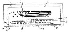
- FIG. 1is a drawing of a postal indicia.
- FIG. 2is a drawing of a two-dimensional bar code that represents in coded form the information contained in material 14 and other information.
- FIG. 3is a drawing of portion 25 of bar code 22 .
- FIG. 4is a drawing of image 27 consisting of bar code 22 repeated m times in the horizontal direction and n times in the vertical direction.
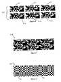
- FIG. 5is a drawing showing the condensing of the six bar codes 22 into one bar code image 28 .
- FIG. 6is a drawing of a mathematical filter 29 that has the same dimensions as bar code image 28 of FIG. 5 .
- FIG. 7is the resulting image 35 of bar code image 28 ( FIG. 5 ) filtered by filter 29 ( FIG. 6 ).
- FIG. 8is a drawing of right half 39 of FIG. 7 .
- FIG. 9is a drawing of left half 38 of FIG. 7 .
- FIG. 9Ais a drawing of left half 38 of FIG. 7 divided into section 43 and section 44 .
- FIG. 9Bis a drawing showing the spreading algorithm applied to section 43 of FIG. 9A .
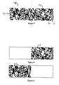
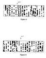
- FIG. 10is a drawing of an image 40 when a spreading algorithm is applied to left half 38 .
- FIG. 11is a drawing of an image 41 when a spread spectrum-like algorithm is applied to right half 9 .
- FIG. 12shows a detailed step of the expansion process.
- FIG. 13is a drawing of image 40 expanded to image 56 .
- FIG. 14is a drawing of image 41 expanded to image 57 .
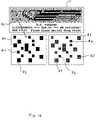
- FIG. 15is a drawing of images 40 and 41 embedded in the graphical material portion of indicia 11 of FIG. 1 .
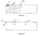
- FIG. 16is a drawing of images 40 and 41 embedded in the graphical material portion of indicia 11 of FIG. 1 , details of the bit map of the 3 ⁇ 3 and 2 ⁇ 2 pixels that comprises section 82 , and an actual image of 3 ⁇ 3 and 2 ⁇ 2 pixels that comprises bit map 80 .
- FIG. 17is a picture 90 of bit map 80 of FIG. 16 and a print 91 of picture 90 .
- Postal indicia 11represents graphic material in the form of an eagle 12 and stars 13 and alphanumeric material 14 .
- Indicia 11also contains a dollar amount 15 ; the date 16 that postal indicia 11 was affixed to mail piece 17 ; the zip code where mail piece 17 was mailed from 18 ; the postal meter serial number 19 ; a security code 20 ; the class of mail 55 ; and the country 21 .
- FIG. 2is a drawing of a two-dimensional bar code 22 that represents in coded form the information contained in material 14 and other information.
- Bar code 22comprises a plurality of black modules 23 and white modules 24 .
- Black modules 23represent a “zero” and white modules 24 represent a “one”.
- Portion 25 of bar code 22represents the zip code 18 of FIG. 1 with the least significant bit on the left.
- FIG. 3is a drawing of portion 25 of bar code 22 .
- the binary representation of portion 25i.e., zip code 18 , is shown by a plurality of ones and zeros 26 .
- FIG. 5is a drawing showing the condensing of the six bar codes 22 into one bar code image 28 .
- FIG. 6is a drawing of a mathematical filter 29 that has the same dimensions as bar code image 28 of FIG. 5 , i.e., a length of 60 pixels and a width of 16 pixels.
- Filter 29may be any arrangement of black pixels 30 and white pixels 31 as long as filter 29 contains the same number of black pixels 30 having a value of “0” and white pixels 31 having a value of “1”.
- Filter 29may be a pseudo random stream of bits such as the output of a cryptographic algorithm like the Digital Encryption Standard (DES).
- DESDigital Encryption Standard
- filter 29may be an exclusive—or of a function of the X coordinate and a function of the Y coordinate as shown in FIG. 6 .
- Filter 29causes a pixel-by-pixel exclusive—or reversal—process when it filters an image.
- pixel of the filteris white there will be a reversal between the image and the calculated filter image; and, when the pixel of the filter is black, there will be no change between the image and the calculated filter image.
- the following chartshows the calculated filter value for different color image pixels and different color filter pixels.
- the filter 29 shown in FIG. 6is applied to the bar code image 28 shown in FIG. 5 to make the redundant bar code image 28 information invisible.
- the filter algorithm implementationis a pixel-by-pixel exclusive—or operation—between the image and the filter.
- FIG. 7is the resulting image 35 of bar code image 28 ( FIG. 5 ) filtered by filter 29 ( FIG. 6 ).
- Resulting image 35is a matrix of sixty horizontal pixels by sixteen vertical pixels that include white pixels 36 and black pixels 37 .
- Image 35has a left half 38 and a right half 39 .
- the number of pixels in left half 38equals the number of pixels in right half 39 . If one would compare bar code image 28 with resulting image 35 , one would observe that bar code image 28 does not correlate with resulting image 35 .
- FIG. 8is a drawing of right half 39 of FIG. 7 .
- FIG. 9is a drawing of left half 38 of FIG. 7 .
- FIG. 9Ais a drawing of left half 38 of FIG. 7 divided into section 43 and section 44 .
- Section 43is shown having black and white pixels.
- Section 44is shown having gray and white pixels.
- FIG. 9Bis a drawing showing the spreading algorithm applied to section 43 of FIG. 9A .
- the spreading algorithmwill be described in the description of FIG. 10 .
- Black pixelsare shown at 45
- white pixelsare shown at 46 .
- Section 43has a region 50 .
- FIG. 10is a drawing of an image 40 when a spread spectrum-like algorithm is applied to left half 38 .
- the spreading algorithmis used to increase the hiding capability and optimal recovery of the information hidden in image 40 .
- the spreading algorithmdisperses the information, i.e., white pixels and black pixels, in a manner that neighboring pixels in image 38 will not be close together in image 40 .
- a spreading algorithmessentially transforms an image into another image by randomizing the rows and columns indexes. The following is an example of a spreading algorithm.
- NKis the size of the row or column
- kis the index of the row or column in the original image.
- FIN(NK,KK,k)returns a permutation of the index k.
- the value of KKis chosen to minimize the correlation between the index and the permuted index.
- the routine INX(NK)returns the selected permutation INDX.
- INDX kis the chosen permuted index in the spread image.
- FIG. 11is a drawing of an image 41 when a spreading algorithm is applied to right half 39 .
- the spreading algorithmis used to increase the hiding capability and optimal recovery of the information hidden in image 41 .
- the spreading algorithmdisperses the information, i.e., white pixels and black pixels, in a manner that the neighboring pixels in image 39 will not be close together in image 41 .
- a spreading algorithmessentially transforms an image into another image by randomizing the rows and columns indexes. An example of a spreading algorithm is shown in the description of FIG. 10 .
- FIG. 12is a drawing of an enlarged view of region 50 of section 43 , and region 50 expanded into region 51 .
- Black pixelsare shown at 45
- white pixelsare shown at 46 .
- Two purposes of expanding an imageis to control the lightness of the background and to provide a grid to enable a low resolution reading.
- FIG. 13is a drawing of image 40 expanded to image 56 .
- Black pixelsare shown at 60
- white pixelsare shown at 61 .
- a cluster of 2 ⁇ 2 dots 60is formed from one black pixel in image 56 .
- No clusteris printed at location 61 to represent a white pixel in image 56 .
- FIG. 14is a drawing of image 41 expanded to image 57 .
- Black pixelsare shown at 62
- white pixelsare shown at 63 .
- a cluster of 3 ⁇ 3 dots 62is formed from one black pixel in image 57 .
- No clusteris printed at location 63 to represent a white pixel in image 57 . It would be obvious to one skilled in the art that many differently sized and shaped clusters may be used and the sham corners of the clusters removed.
- FIG. 15is a drawing of images 40 and 41 embedded in the graphical material portion of indicia 11 of FIG. 1 .
- Image 40 black pixelsare shown at 67
- image 41 black pixelsare shown at 65 .
- the manner in which images 40 and 41 change in appearance when they are photocopied,is described in the description of FIG. 17 .
- FIG. 16is a drawing of images 40 and 41 embedded in the graphical material portion of indicia 11 of FIG. 1 ; details of the bit map of the 3 ⁇ 3 and 2 ⁇ 2 pixels that comprise section 82 ; and actual image of 3 ⁇ 3 and 2 ⁇ 2 pixels that comprise bit map 80 .
- a bit map 80 and actual scanned image 81 for section 82are shown for section 82 of indicia 11 .
- Bit map 80includes 3 ⁇ 3 pixels 83 and 2 ⁇ 2 pixels 84 .
- Actual scanned image 81includes 3 ⁇ 3 pixels 85 and 2 ⁇ 2 pixels 86 .
- FIG. 17is a picture 90 of bit map 80 of FIG. 16 and a print 91 of picture 90 .
- Picture 90shows 2 ⁇ 2 pixels at 92 and 3 ⁇ 3 pixels at 93 .
- Print 91shows 2 ⁇ 2 pixels 94 and 3 ⁇ 3 pixels 95 .
- the scanning and printing processmakes the 2 ⁇ 2 pixels 92 of picture 90 larger than the 2 ⁇ 2 pixels 94 of print 91 .
- the spot size of a printed dotis larger than the pixel spacing to achieve complete coverage in the printed image. Due to ink spread and random ink paper interactions, the spread is not uniform, resulting in shapes that are irregular with blurred and ragged edges.
- the scanner pixelin general, will not be aligned with the edges of the printed modules. This has the effect of increasing the effective print growth and edge raggedness.
Landscapes
- Physics & Mathematics (AREA)
- Engineering & Computer Science (AREA)
- General Physics & Mathematics (AREA)
- Theoretical Computer Science (AREA)
- Health & Medical Sciences (AREA)
- Electromagnetism (AREA)
- General Health & Medical Sciences (AREA)
- Toxicology (AREA)
- Artificial Intelligence (AREA)
- Computer Vision & Pattern Recognition (AREA)
- Editing Of Facsimile Originals (AREA)
Abstract
Description
| COLOR OF PIXEL | COLOR OF PIXEL IN | CALCULATED FILTER |
| IMAGE | FILTER | IMAGE |
| White = 1 | White = 1 | Black = 0 |
| Black = 0 | White = 1 | White = 1 |
| White = 1 | Black = 0 | White = 1 |
| Black = 0 | Black = 0 | Black = 0 |
Claims (12)
Priority Applications (1)
| Application Number | Priority Date | Filing Date | Title |
|---|---|---|---|
| US10/087,492US7013024B2 (en) | 2001-04-13 | 2002-03-01 | Method for reading information that has been embedded in an image |
Applications Claiming Priority (2)
| Application Number | Priority Date | Filing Date | Title |
|---|---|---|---|
| US28356501P | 2001-04-13 | 2001-04-13 | |
| US10/087,492US7013024B2 (en) | 2001-04-13 | 2002-03-01 | Method for reading information that has been embedded in an image |
Publications (2)
| Publication Number | Publication Date |
|---|---|
| US20030002711A1 US20030002711A1 (en) | 2003-01-02 |
| US7013024B2true US7013024B2 (en) | 2006-03-14 |
Family
ID=26777030
Family Applications (1)
| Application Number | Title | Priority Date | Filing Date |
|---|---|---|---|
| US10/087,492Expired - LifetimeUS7013024B2 (en) | 2001-04-13 | 2002-03-01 | Method for reading information that has been embedded in an image |
Country Status (1)
| Country | Link |
|---|---|
| US (1) | US7013024B2 (en) |
Cited By (9)
| Publication number | Priority date | Publication date | Assignee | Title |
|---|---|---|---|---|
| US20080144116A1 (en)* | 2006-12-18 | 2008-06-19 | Pitney Bowes Incorporated | Method and system for applying an image-dependent dynamic watermark to postal indicia |
| US20080158588A1 (en)* | 2006-12-27 | 2008-07-03 | Pitney Bowes Incorporated | Method and system for generating copy detection pattern having a fixed component and dynamic component |
| CN102073828A (en)* | 2009-11-23 | 2011-05-25 | 柯尼卡美能达系统研究所公司 | Document authentication using hierarchical barcode stamps to detect alterations of barcode |
| US20120063676A1 (en)* | 2006-04-19 | 2012-03-15 | A T Communications Co., Ltd. | Two-dimensional code with a logo |
| US9519942B2 (en)* | 2015-02-17 | 2016-12-13 | Sys-Tech Solutions, Inc. | Methods and a computing device for determining whether a mark is genuine |
| US9940572B2 (en) | 2015-02-17 | 2018-04-10 | Sys-Tech Solutions, Inc. | Methods and a computing device for determining whether a mark is genuine |
| CN109344946A (en)* | 2018-10-12 | 2019-02-15 | 广东石油化工学院 | Two-dimensional code anti-counterfeiting method based on complementary recognition of image plane figure segmentation |
| US10235597B2 (en) | 2015-06-16 | 2019-03-19 | Sys-Tech Solutions, Inc. | Methods and a computing device for determining whether a mark is genuine |
| US10380601B2 (en) | 2012-03-01 | 2019-08-13 | Sys-Tech Solutions, Inc. | Method and system for determining whether a mark is genuine |
Families Citing this family (5)
| Publication number | Priority date | Publication date | Assignee | Title |
|---|---|---|---|---|
| CN1981526A (en)* | 2004-05-05 | 2007-06-13 | 皇家飞利浦电子股份有限公司 | Selective video blanking |
| US8467566B2 (en)* | 2005-10-06 | 2013-06-18 | Pitney Bowes Inc. | Method for detecting fraud in a printed image |
| US7747544B2 (en)* | 2005-12-07 | 2010-06-29 | Pitney Bowes Inc. | Meter tape with location indicator used for unique identification |
| US20070136213A1 (en)* | 2005-12-08 | 2007-06-14 | Pitney Bowes Incorporated | Inline system to detect and show proof of indicia fraud |
| JP4819723B2 (en)* | 2006-03-16 | 2011-11-24 | 株式会社リコー | Information extraction apparatus, information extraction method, information extraction program, and recording medium |
Citations (16)
| Publication number | Priority date | Publication date | Assignee | Title |
|---|---|---|---|---|
| US5635694A (en)* | 1995-09-27 | 1997-06-03 | Xerox Corporation | System and method for embedding machine coded destination information into a postal mark |
| US5825892A (en) | 1996-10-28 | 1998-10-20 | International Business Machines Corporation | Protecting images with an image watermark |
| US5829895A (en) | 1995-12-27 | 1998-11-03 | Pitney Bowes Inc. | Method for printing an image indicative of value such as a postal indicia |
| US5946414A (en) | 1998-08-28 | 1999-08-31 | Xerox Corporation | Encoding data in color images using patterned color modulated image regions |
| US6102592A (en)* | 1997-01-29 | 2000-08-15 | Neopost Limited | Method and apparatus for printing and prevention of copying of postage indicia |
| US20010022848A1 (en)* | 1994-03-17 | 2001-09-20 | Rhoads Geoffrey B. | Method of producing a security document |
| US6317115B1 (en) | 1993-12-09 | 2001-11-13 | Canon Kabushiki Kaisha | System, apparatus and method in which a high resolution image editor is connected to a host computer for processing low resolution image data |
| US6332194B1 (en) | 1998-06-05 | 2001-12-18 | Signafy, Inc. | Method for data preparation and watermark insertion |
| US6359998B1 (en) | 1998-04-23 | 2002-03-19 | 3Com Corporation | Method and apparatus for wavelet-based digital watermarking |
| US6415983B1 (en)* | 1999-02-26 | 2002-07-09 | Canada Post Corporation | Unique identifier bar code on stamps and apparatus and method for monitoring stamp usage with identifier bar codes |
| US20030028497A1 (en)* | 1998-07-22 | 2003-02-06 | Jp Leon | Method and apparatus for postage label authentication |
| US6611598B1 (en)* | 1998-01-12 | 2003-08-26 | Unisys Corporation | Self-authentication of value documents using encoded indices |
| US6636615B1 (en)* | 1998-01-20 | 2003-10-21 | Digimarc Corporation | Methods and systems using multiple watermarks |
| US6768807B1 (en) | 1999-03-24 | 2004-07-27 | Kabushiki Kaisha Toshiba | Digital watermark embedding device, digital watermark detection device, digital information distribution device, and, storage medium |
| US20040190751A1 (en) | 1995-05-08 | 2004-09-30 | Digimarc Corporation | Method for utilizing fragile watermark for enhanced security |
| US6882442B2 (en) | 2000-04-05 | 2005-04-19 | Gregory B. Roberts | System and method for bar code rendering and recognition |
- 2002
- 2002-03-01USUS10/087,492patent/US7013024B2/ennot_activeExpired - Lifetime
Patent Citations (16)
| Publication number | Priority date | Publication date | Assignee | Title |
|---|---|---|---|---|
| US6317115B1 (en) | 1993-12-09 | 2001-11-13 | Canon Kabushiki Kaisha | System, apparatus and method in which a high resolution image editor is connected to a host computer for processing low resolution image data |
| US20010022848A1 (en)* | 1994-03-17 | 2001-09-20 | Rhoads Geoffrey B. | Method of producing a security document |
| US20040190751A1 (en) | 1995-05-08 | 2004-09-30 | Digimarc Corporation | Method for utilizing fragile watermark for enhanced security |
| US5635694A (en)* | 1995-09-27 | 1997-06-03 | Xerox Corporation | System and method for embedding machine coded destination information into a postal mark |
| US5829895A (en) | 1995-12-27 | 1998-11-03 | Pitney Bowes Inc. | Method for printing an image indicative of value such as a postal indicia |
| US5825892A (en) | 1996-10-28 | 1998-10-20 | International Business Machines Corporation | Protecting images with an image watermark |
| US6102592A (en)* | 1997-01-29 | 2000-08-15 | Neopost Limited | Method and apparatus for printing and prevention of copying of postage indicia |
| US6611598B1 (en)* | 1998-01-12 | 2003-08-26 | Unisys Corporation | Self-authentication of value documents using encoded indices |
| US6636615B1 (en)* | 1998-01-20 | 2003-10-21 | Digimarc Corporation | Methods and systems using multiple watermarks |
| US6359998B1 (en) | 1998-04-23 | 2002-03-19 | 3Com Corporation | Method and apparatus for wavelet-based digital watermarking |
| US6332194B1 (en) | 1998-06-05 | 2001-12-18 | Signafy, Inc. | Method for data preparation and watermark insertion |
| US20030028497A1 (en)* | 1998-07-22 | 2003-02-06 | Jp Leon | Method and apparatus for postage label authentication |
| US5946414A (en) | 1998-08-28 | 1999-08-31 | Xerox Corporation | Encoding data in color images using patterned color modulated image regions |
| US6415983B1 (en)* | 1999-02-26 | 2002-07-09 | Canada Post Corporation | Unique identifier bar code on stamps and apparatus and method for monitoring stamp usage with identifier bar codes |
| US6768807B1 (en) | 1999-03-24 | 2004-07-27 | Kabushiki Kaisha Toshiba | Digital watermark embedding device, digital watermark detection device, digital information distribution device, and, storage medium |
| US6882442B2 (en) | 2000-04-05 | 2005-04-19 | Gregory B. Roberts | System and method for bar code rendering and recognition |
Cited By (14)
| Publication number | Priority date | Publication date | Assignee | Title |
|---|---|---|---|---|
| US20120063676A1 (en)* | 2006-04-19 | 2012-03-15 | A T Communications Co., Ltd. | Two-dimensional code with a logo |
| US8526670B2 (en)* | 2006-04-19 | 2013-09-03 | A T Communications Co., Ltd. | Two-dimensional code with a logo |
| US7839538B2 (en) | 2006-12-18 | 2010-11-23 | Pitney Bowes Inc. | Method and system for applying an image-dependent dynamic watermark to postal indicia |
| US20080144116A1 (en)* | 2006-12-18 | 2008-06-19 | Pitney Bowes Incorporated | Method and system for applying an image-dependent dynamic watermark to postal indicia |
| US20080158588A1 (en)* | 2006-12-27 | 2008-07-03 | Pitney Bowes Incorporated | Method and system for generating copy detection pattern having a fixed component and dynamic component |
| US8430301B2 (en)* | 2009-11-23 | 2013-04-30 | Konica Minolta Laboratory U.S.A., Inc. | Document authentication using hierarchical barcode stamps to detect alterations of barcode |
| US20110121066A1 (en)* | 2009-11-23 | 2011-05-26 | Konica Minolta Systems Laboratory, Inc. | Document authentication using hierarchical barcode stamps to detect alterations of barcode |
| CN102073828A (en)* | 2009-11-23 | 2011-05-25 | 柯尼卡美能达系统研究所公司 | Document authentication using hierarchical barcode stamps to detect alterations of barcode |
| CN102073828B (en)* | 2009-11-23 | 2016-03-16 | 柯尼卡美能达系统研究所公司 | Classification bar code stamp is used to carry out the document authentication of the change of detector bar shape code |
| US10380601B2 (en) | 2012-03-01 | 2019-08-13 | Sys-Tech Solutions, Inc. | Method and system for determining whether a mark is genuine |
| US9519942B2 (en)* | 2015-02-17 | 2016-12-13 | Sys-Tech Solutions, Inc. | Methods and a computing device for determining whether a mark is genuine |
| US9940572B2 (en) | 2015-02-17 | 2018-04-10 | Sys-Tech Solutions, Inc. | Methods and a computing device for determining whether a mark is genuine |
| US10235597B2 (en) | 2015-06-16 | 2019-03-19 | Sys-Tech Solutions, Inc. | Methods and a computing device for determining whether a mark is genuine |
| CN109344946A (en)* | 2018-10-12 | 2019-02-15 | 广东石油化工学院 | Two-dimensional code anti-counterfeiting method based on complementary recognition of image plane figure segmentation |
Also Published As
| Publication number | Publication date |
|---|---|
| US20030002711A1 (en) | 2003-01-02 |
Similar Documents
| Publication | Publication Date | Title |
|---|---|---|
| US7191336B2 (en) | Method for embedding information in an image | |
| EP1456812B1 (en) | Generating graphical codes by halftoning with embedded graphical encoding | |
| US7013024B2 (en) | Method for reading information that has been embedded in an image | |
| CN1882026B (en) | Method of generating information embedded halftone screen code | |
| EP1360640B1 (en) | Document printed with graphical symbols which encode information | |
| KR100378911B1 (en) | Information processing method | |
| AU748031C (en) | Anti-counterfeiting method and apparatus using digital screening | |
| EP0466146B1 (en) | Graphic matter and process and apparatus for producing, transmitting and reading the same | |
| EP0988151B1 (en) | Security document containing encoded data block | |
| EP1825422B1 (en) | Embedded optical signatures in documents | |
| US6886863B1 (en) | Secure document with self-authenticating, encryptable font | |
| EP1417649B1 (en) | Scalable, fraud resistant graphical payment indicia | |
| EP2490158B1 (en) | Embedded optical signatures in documents | |
| CA2340882A1 (en) | Method for embedding non-intrusive encoded data in printed matter and system for reading same | |
| KR20000048145A (en) | Ticket issuing method, ticket issuing system and ticket collating method | |
| MXPA06001533A (en) | Machine readable data. | |
| US8205086B2 (en) | Watermark information embedding device and method, watermark information detecting device and method, watermarked document | |
| US20070136213A1 (en) | Inline system to detect and show proof of indicia fraud | |
| HK1055344A (en) | Anti-counterfeiting decoding method and apparatus | |
| AU2008207632A1 (en) | Encoding information in a document | |
| AU2002229923A1 (en) | Document printed with graphical symbols which encode information |
Legal Events
| Date | Code | Title | Description |
|---|---|---|---|
| AS | Assignment | Owner name:PITNEY BOWES INC., CONNECTICUT Free format text:ASSIGNMENT OF ASSIGNORS INTEREST;ASSIGNORS:CORDERY, ROBERT A.;ZELLER. CLAUDE;MACKAY, DONALD G.;AND OTHERS;REEL/FRAME:012671/0593;SIGNING DATES FROM 20020221 TO 20020226 | |
| STCF | Information on status: patent grant | Free format text:PATENTED CASE | |
| FPAY | Fee payment | Year of fee payment:4 | |
| FPAY | Fee payment | Year of fee payment:8 | |
| FPAY | Fee payment | Year of fee payment:12 | |
| AS | Assignment | Owner name:JPMORGAN CHASE BANK, N.A., AS ADMINISTRATIVE AGENT Free format text:SECURITY INTEREST;ASSIGNORS:PITNEY BOWES INC.;NEWGISTICS, INC.;BORDERFREE, INC.;AND OTHERS;REEL/FRAME:050905/0640 Effective date:20191101 Owner name:JPMORGAN CHASE BANK, N.A., AS ADMINISTRATIVE AGENT, NEW YORK Free format text:SECURITY INTEREST;ASSIGNORS:PITNEY BOWES INC.;NEWGISTICS, INC.;BORDERFREE, INC.;AND OTHERS;REEL/FRAME:050905/0640 Effective date:20191101 | |
| AS | Assignment | Owner name:ALTER DOMUS (US) LLC, ILLINOIS Free format text:SECURITY INTEREST;ASSIGNORS:PITNEY BOWES, INC.;PITNEY BOWES GLOBAL LOGISTICS LLC;REEL/FRAME:064444/0313 Effective date:20230731 | |
| AS | Assignment | Owner name:PITNEY BOWES, INC., CONNECTICUT Free format text:RELEASE BY SECURED PARTY;ASSIGNOR:ALTER DOMUS (US) LLC;REEL/FRAME:070154/0532 Effective date:20250207 | |
| AS | Assignment | Owner name:PITNEY BOWES, INC., CONNECTICUT Free format text:RELEASE OF PATENT SECURITY AGREEMENT;ASSIGNOR:JPMORGAN CHASE BANK, N.A., AS ADMINISTRATIVE AGENT;REEL/FRAME:070256/0396 Effective date:20250207 |