US7013021B2 - Watermark detection utilizing regions with higher probability of success - Google Patents
Watermark detection utilizing regions with higher probability of successDownload PDFInfo
- Publication number
- US7013021B2 US7013021B2US09/945,244US94524401AUS7013021B2US 7013021 B2US7013021 B2US 7013021B2US 94524401 AUS94524401 AUS 94524401AUS 7013021 B2US7013021 B2US 7013021B2
- Authority
- US
- United States
- Prior art keywords
- image
- detection
- variance
- watermark
- blocks
- Prior art date
- Legal status (The legal status is an assumption and is not a legal conclusion. Google has not performed a legal analysis and makes no representation as to the accuracy of the status listed.)
- Expired - Lifetime, expires
Links
Images


Classifications
- G—PHYSICS
- G06—COMPUTING OR CALCULATING; COUNTING
- G06T—IMAGE DATA PROCESSING OR GENERATION, IN GENERAL
- G06T1/00—General purpose image data processing
- G06T1/0021—Image watermarking
- G06T1/005—Robust watermarking, e.g. average attack or collusion attack resistant
- G06T1/0071—Robust watermarking, e.g. average attack or collusion attack resistant using multiple or alternating watermarks
- G—PHYSICS
- G06—COMPUTING OR CALCULATING; COUNTING
- G06T—IMAGE DATA PROCESSING OR GENERATION, IN GENERAL
- G06T1/00—General purpose image data processing
- G06T1/0021—Image watermarking
- G06T1/005—Robust watermarking, e.g. average attack or collusion attack resistant
- G06T1/0078—Robust watermarking, e.g. average attack or collusion attack resistant using multiple thresholds
- H—ELECTRICITY
- H04—ELECTRIC COMMUNICATION TECHNIQUE
- H04N—PICTORIAL COMMUNICATION, e.g. TELEVISION
- H04N1/00—Scanning, transmission or reproduction of documents or the like, e.g. facsimile transmission; Details thereof
- H04N1/32—Circuits or arrangements for control or supervision between transmitter and receiver or between image input and image output device, e.g. between a still-image camera and its memory or between a still-image camera and a printer device
- H04N1/32101—Display, printing, storage or transmission of additional information, e.g. ID code, date and time or title
- H04N1/32144—Display, printing, storage or transmission of additional information, e.g. ID code, date and time or title embedded in the image data, i.e. enclosed or integrated in the image, e.g. watermark, super-imposed logo or stamp
- H04N1/32149—Methods relating to embedding, encoding, decoding, detection or retrieval operations
- H04N1/32154—Transform domain methods
- H04N1/32187—Transform domain methods with selective or adaptive application of the additional information, e.g. in selected frequency coefficients
- H—ELECTRICITY
- H04—ELECTRIC COMMUNICATION TECHNIQUE
- H04N—PICTORIAL COMMUNICATION, e.g. TELEVISION
- H04N1/00—Scanning, transmission or reproduction of documents or the like, e.g. facsimile transmission; Details thereof
- H04N1/32—Circuits or arrangements for control or supervision between transmitter and receiver or between image input and image output device, e.g. between a still-image camera and its memory or between a still-image camera and a printer device
- H04N1/32101—Display, printing, storage or transmission of additional information, e.g. ID code, date and time or title
- H04N1/32144—Display, printing, storage or transmission of additional information, e.g. ID code, date and time or title embedded in the image data, i.e. enclosed or integrated in the image, e.g. watermark, super-imposed logo or stamp
- H04N1/32149—Methods relating to embedding, encoding, decoding, detection or retrieval operations
- H04N1/32203—Spatial or amplitude domain methods
- H04N1/32229—Spatial or amplitude domain methods with selective or adaptive application of the additional information, e.g. in selected regions of the image
- H04N1/32235—Spatial or amplitude domain methods with selective or adaptive application of the additional information, e.g. in selected regions of the image in highly textured regions
- H—ELECTRICITY
- H04—ELECTRIC COMMUNICATION TECHNIQUE
- H04N—PICTORIAL COMMUNICATION, e.g. TELEVISION
- H04N1/00—Scanning, transmission or reproduction of documents or the like, e.g. facsimile transmission; Details thereof
- H04N1/32—Circuits or arrangements for control or supervision between transmitter and receiver or between image input and image output device, e.g. between a still-image camera and its memory or between a still-image camera and a printer device
- H04N1/32101—Display, printing, storage or transmission of additional information, e.g. ID code, date and time or title
- H04N1/32144—Display, printing, storage or transmission of additional information, e.g. ID code, date and time or title embedded in the image data, i.e. enclosed or integrated in the image, e.g. watermark, super-imposed logo or stamp
- H04N1/32149—Methods relating to embedding, encoding, decoding, detection or retrieval operations
- H04N1/32203—Spatial or amplitude domain methods
- H04N1/32229—Spatial or amplitude domain methods with selective or adaptive application of the additional information, e.g. in selected regions of the image
- H04N1/3224—Spatial or amplitude domain methods with selective or adaptive application of the additional information, e.g. in selected regions of the image in edge regions
- G—PHYSICS
- G06—COMPUTING OR CALCULATING; COUNTING
- G06T—IMAGE DATA PROCESSING OR GENERATION, IN GENERAL
- G06T2201/00—General purpose image data processing
- G06T2201/005—Image watermarking
- G06T2201/0065—Extraction of an embedded watermark; Reliable detection
- H—ELECTRICITY
- H04—ELECTRIC COMMUNICATION TECHNIQUE
- H04N—PICTORIAL COMMUNICATION, e.g. TELEVISION
- H04N2201/00—Indexing scheme relating to scanning, transmission or reproduction of documents or the like, and to details thereof
- H04N2201/32—Circuits or arrangements for control or supervision between transmitter and receiver or between image input and image output device, e.g. between a still-image camera and its memory or between a still-image camera and a printer device
- H04N2201/3201—Display, printing, storage or transmission of additional information, e.g. ID code, date and time or title
- H04N2201/3225—Display, printing, storage or transmission of additional information, e.g. ID code, date and time or title of data relating to an image, a page or a document
- H04N2201/3233—Display, printing, storage or transmission of additional information, e.g. ID code, date and time or title of data relating to an image, a page or a document of authentication information, e.g. digital signature, watermark
- H—ELECTRICITY
- H04—ELECTRIC COMMUNICATION TECHNIQUE
- H04N—PICTORIAL COMMUNICATION, e.g. TELEVISION
- H04N2201/00—Indexing scheme relating to scanning, transmission or reproduction of documents or the like, and to details thereof
- H04N2201/32—Circuits or arrangements for control or supervision between transmitter and receiver or between image input and image output device, e.g. between a still-image camera and its memory or between a still-image camera and a printer device
- H04N2201/3201—Display, printing, storage or transmission of additional information, e.g. ID code, date and time or title
- H04N2201/3269—Display, printing, storage or transmission of additional information, e.g. ID code, date and time or title of machine readable codes or marks, e.g. bar codes or glyphs
- H04N2201/327—Display, printing, storage or transmission of additional information, e.g. ID code, date and time or title of machine readable codes or marks, e.g. bar codes or glyphs which are undetectable to the naked eye, e.g. embedded codes
Definitions
- the present inventionis also related to U.S. patent application Ser. Nos. 09/771,340, filed Jan. 26, 2001 (published as US 2003-0016841 A1), and Ser. No. 09/503,881, filed Feb. 14, 2000 (now U.S. Pat. No. 6,614,914).
- the present inventionrelates to steganography and, more particularly, to the detection of digital watermarks in media such as images, video and audio signals.
- watermarking systemsredundantly embed the same watermark data in multiple regions of an image.
- Often watermarking systemsembed data in images in a perceptually adaptive manner. That is, the amount of watermark signal in each region of an image is adjusted in accordance with the characteristics of the image in the particular region. The watermark may even be absent in some regions of the image.
- the purpose of so adjusting the watermark signalis to insure that the watermark signal will not be visible to an ordinary viewer of the image. Since the strength of the watermark signal varies from region to region, the signal is more easily detected in some regions of an image than in other regions of the image.
- Systems for detecting watermarksgenerally sequentially examine the various regions of an image, seeking to detect the watermark.
- the amount of computational resources availableis limited and if a watermark is not detected in a region as a result of applying a certain amount of computational effort, the detection operation moves on to the next region of the image and the process is repeated.
- the present inventionenables detection of the presence of a watermark in an efficient manner.
- One embodimentinvolves a multi-step process. First, the image is examined to determine which regions of the image have characteristics such that there is a high probability that a watermark signal can be detected in that region of the image. Next the regions that have a high probability that a watermark can be detected (in contrast to all regions of the image) are examined to find watermark data. In order to determine the probability of finding watermark data in a particular region of an image, the amount of “variance” in the intensity of the pixels in the region is examined. For example a region that is entirely white or entirely black has zero variance. Such a region cannot carry watermark data; hence regions with zero or low variance can be eliminated from further processing.
- regions with high varianceare located, these regions are next examined to look for regions with edges between areas of different luminance, which are spread over the entire region.
- the regions with the high variance and with edginess that is spread widely in the regionare selected for further processing to detect watermark data.
- regions with high varianceare not always indicative of a high detection probability.
- the detection processcan be enhanced by filtering the data prior to applying a watermark detection program so as to increase the signal to noise ratio of the watermark signal.
- a high pass filtere.g. a Laplacian operator
- This filtering operationin effect establishes a new intensity value for each pixel in the region.
- a nonlinear operatore.g. a signum function
- the resulting data in each regionis then processed in a normal manner to detect watermark data.
- additional probability factorsare used to identify image regions having a high probability of containing watermark data therein.
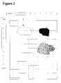
- FIG. 1shows an image with different regions.
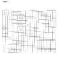
- FIG. 2shows the FIG. 1 image divided into regions for processing.
- FIG. 3illustrates the pixels in different regions of an image.
- FIG. 4shows a flow diagram for one embodiment of the present invention.
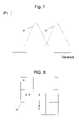
- FIG. 5shows a flow diagram for additional steps that can be used.
- FIG. 6shows a system diagram for practicing an embodiment of the present invention.
- FIG. 7is a graph showing a relative probability of a successful watermark detection for a given area having a particular variance.
- FIG. 8shows an edginess detection method in relation to an image portion.
- FIGS. 9 a – 9 cshow another edginess detection method in relation to an image portion.
- FIGS. 10 a – 10 cshow an image portion that is divided by regions for processing.
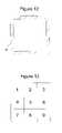
- FIG. 11shows city-block and diagonal distances between centers of detection blocks.
- FIG. 12shows a keep away zone near a border of an image.
- FIG. 13shows a neighborhood of detection blocks.
- FIG. 14illustrates a system diagram for practicing an embodiment of the present invention.
- Digital watermarksare generally inserted into images in a redundant manner. That is, images are divided into regions and the same digital watermark data is inserted into each region of the image.
- the ability of a particular region of an image to effectively carry digital watermark datadepends upon the characteristics of the image in the particular region. Different areas in an image may have more or less ability to carry watermark data. For example an area in an image that is entirely white or entirely black will not have the ability to carry watermark data without changing the appearance of the area.
- Modem watermarking programsuse visually perceptual adaptive techniques when inserting watermark data into an image. The amount of watermark energy inserted into a region is adjusted depending on the characteristics of the region so as to avoid changing the visual appearance of the image. For example, no watermark energy would be applied to an area of an image that is entirely white or entirely black.
- Watermark detection programsgenerally divide an image into regions and then sequentially try to read watermark data from each of the regions in the image. Generally several attempts are made to detect watermark data in each region of an image. This is a computationally costly endeavor.
- the present inventionshortens the processing time and reduces the computational power required to find a watermark in an image by first identifying those regions of the image that have a high probability that a watermark can be detected in the region. Then, regions with high probability rather than all regions are examined to locate watermark data.
- probability factorsthere are a number of different probability factors that can be considered in connection with watermark detection. For example, one can consider the probability that data found by a watermark detection program is in fact identical to the data that was inserted by the program that inserted the watermark. The probability discussed herein is different. The probability factors discussed herein relative to the present invention relates to the probability that a region of an image with certain characteristics can in fact be carrying watermark data.
- FIG. 1illustrates an image 2 , which has a number of different identified regions. Regions with various types of specific characteristics have been shown in order to illustrate the invention. Naturally in most images the regions would not be as pronounced as those shown in FIG. 1 and there would be a variety of types of regions over the entire image 2 .
- the present inventionis applicable to any type of image.
- the special image shown in FIG. 1is selected only as an example to illustrate the principles of the invention in an easily illustrated manner.
- region 10is entirely white
- region 11is entirely black
- region 12the pixels of the image have a variety of luminance values. If a perceptually adaptive watermarking program were used to insert watermark data in an image such as image 2 , no watermark data would be inserted in regions 10 , 11 . Thus, a program, which tried to detect watermark data in regions 10 , and 11 , would spend time examining these regions, but it would find no watermark data.
- FIG. 2shows the image 2 divided into regions. These regions can also be referred to as detection blocks.
- a typical watermark detection programwould process the regions of an image (such as those regions shown in FIG. 2 ) in some sequential order. Each region would be examined to determine if watermark data could be detected. Such examination requires a significant amount of time and/or computational resources. In some applications time and/or computational resources are limited.
- the present inventionprovides a way to pre-process or filter an image to determine the regions that are most likely to contain watermark data.
- the initial processing of each regionthat is, the initial filtering, is done very quickly and the regions, which have the most probability of yielding watermark data, are selected for further processing to actually detect the watermark data. That is, the time consuming watermark detection algorithms are only applied to the regions, which have a higher probability of providing watermark data.
- the present inventionoptionally can use only part of the image data in order to speedup processing. For example, high-resolution data can be down-sampled (e.g., either directly or after applying antialiasing filters) to a lower resolution for analysis.
- FIG. 3illustrates pixels in an image. It should be noted that for convenience of illustration, only a limited number of pixels are shown in FIG. 3 .
- the 4 ⁇ 4 blocksare shown for convenience of illustration. Of course the blocks can range in size from 4 to 500 pixels by 4 to 500 pixels, or more.
- imagesare scanned at resolutions higher than 75 pixels per inch (resolutions of 300, 600 and 1200 pixels per inch are common) and the regions examined by watermarking programs would generally cover many more pixels than the regions shown in FIG. 3 .
- the limited number of pixels shown in FIG. 3is sufficient to explain the principles of the present invention.
- area A of FIG. 3all of the pixels have a luminance value of zero. This area corresponds to an area such as area row c column 3 in FIG. 2 where the entire region is white. In area B all the pixels have a luminance value of 9. Area B corresponds to an area such as the area in row c column 7 in FIG. 2 where all of the pixels are black. In area C the luminance value per pixel varies between 0 and 9. Area C corresponds to an area such as the area in row g column 7 in FIG. 2 where the pixels have a range of luminance. Since the pixels in area A all have a luminance of 0, there is no possibility that this region contains watermark data.
- region Bsince all the pixels in region B have a luminance value of 9, there is no possibility that region B contains watermark data.
- the pixels in region Chave a variety of luminance values; hence, there is a possibility that this region does contain watermark data.
- the present inventionis directed to detecting the area of an image where there is sufficient variance in the luminance of the pixels in the region that the region could contain watermark data.
- an “edginess” factor(discussed below) can be used to select between regions that have the same or similar variance. In such a case, a region having a higher edginess factor is selected over a region with a lower edginess factor, when their variance is equal.
- the detection operationproceeds in accordance with the steps shown in FIG. 4 .
- First as indicated by block 21the image being examined is scanned to detect the luminance of the pixels in the image.
- the pixelsare broken into regions. For example each region can be square and have in the order of 10000 to 40000 pixels (that is, in the order of 100 to 200 pixels square).
- the exact number of pixels in each regiondepends on the characteristics of the particular detection program used. There is, however, a general advantage of using smaller regions (e.g., 8 ⁇ 8 through 64 ⁇ 64) to calculate variance. Namely, a smaller region is less likely to be affected by image rotation. There is a tradeoff for selecting a smaller region, however, since the variance estimate is less statistically reliable due to the smaller number of pixel samples.
- the regionis eliminated from further consideration.
- the threshold value selectedwill depend upon the size of the regions into which the detection program divides the image and upon the characteristics of the watermark as measured over a representative set of images. However, for a typical image with a program that divides the image into regions, which are in the range of about 100,000 to 300,000 pixels, the value can be in a range of 100 to 500. Of course the pixel range can be smaller if a lower resolution (e.g., 100 dpi) image (or image area) is evaluated.
- An optimal minimum variance thresholdis found to vary with resolution. That is, the higher the resolution, the higher the minimum variance should be. This is particularly the case when high-resolution data is efficiently down-sampled, e.g., without using antialiasing filters.
- Table 1shows a relationship between optimal minimum variance thresholds and resolution. Of course, these minimum values may vary depending on image characteristics, scanner error, precision vs. efficiency requirements, etc. For instance, these minimum values may decrease depending on the above considerations.
- Variance of pixels in a regiontends to increase with resolution. This is particularly true at higher resolutions where nearest neighbor down sampled data (which may be highly aliased) is used to calculate variance. Increasing the variance threshold with resolution prevents selection of blocks with spurious variance caused by borders, paper texture, noise etc.
- Another variance determination methodrelies on a distribution formed by gathering a statistically significant amount of variance data across a broad range of images. Separate distributions d 1 and d 2 in FIG. 7 are computed for regions that have a high likelihood of successfully detecting a watermark and for regions that have a low likelihood of successfully detecting a watermark, respectively.
- a probability value associated with a variance for a detection blocke.g., a probability value indicating a likelihood of finding a watermark signal in a particular region having a given variance value, can then be determined for any given variance value. Thresholds can either be determined empirically, e.g., through Bayes' Rule or other hypothesis tests.
- This probability valueis compared against a threshold or a set of thresholds to decide whether to keep the particular variance block.
- a look up table or software algorithmis preferably used to implement the distribution shown in FIG. 7 . Note that the distributions shown in FIG. 7 are for illustrative purposes only. Indeed, the actual distribution could be different, e.g., multi-modal, non-Gaussian or a mixture of Gaussians. Also, the principles discussed with respect to FIG. 7 can be extended to other metrics as well (e.g., variance and edges) to form multivariate distributions.
- a statistically significant number of variance valuesare determined from a respective number of sampled variance detection blocks.
- Each of the sampled variance detection blocksis read to determine whether it contains a watermark signal. This detection data is used to generate the probability distribution curves for given variances.
- the area in row c column 6contains the border between black area 11 and the remainder of the image. In areas such as the area at row c column 6 , the variance in luminance would be high due to the edge effect; however, the high variance in luminance in an area such as row c column 6 would not indicate a high probability of finding watermark data. In a region such as row c column 6 the “edginess spread” is low. If a region has a low “edginess spread”, the probability of finding watermark data is relatively low.
- regions with high luminance variation valuesare found, those regions are tested to determine “edginess spread”. That is, to locate regions where the variance is concentrated along a division between regions each of which have a low variance. Regions where variance in luminance is concentrated along a division between regions, each of which has a low variance in luminance, are said to have a low edginess spread.
- ES(Sum of NNPI for all pixels)/total number of pixels, where T 1 is a “threshold” with a value selected to be near the average value of NPI. The above calculation gives a second value (ES or edginess spread) for each region.
- the luminance variance value and the edginess-spread valueare then combined to give a “probability index” which indicates the probability of finding a watermark in a particular region.
- a difference operatore.g., a Sobel operator, etc.
- Sobel operatore.g., a Sobel operator, etc.
- edginessis determined by evaluating some of a pixel's (or area's) neighbors in comparison to that pixel. For example, a difference in graylevels (or color data) between neighboring pixels is compared to determine an edge or edginess value.
- area xis compared to its horizontal (h) neighbor and vertical neighbor (V) to determine an edginess count.
- an edginess countis preferably incremented when:
- the edginess countis incremented when:
- This processcan be repeated for some or all of the areas within the edginess determination block 20 .
- the neighboring h pixelis preferably zero (0).
- a pixel value outside of block 20 that is located in the horizontal position his used.
- the total edginess count for block 20can be compared against a predetermined number to determine whether to further use block 20 in the watermark detection process. Or the edginess count can be used to rank various edginess determination blocks. Of course this process can be modified without deviating from the scope of our invention. For example, instead of sampling a left horizontal neighbor, a right horizontal neighbor can be sampled. And instead of looking down to the vertical neighbor, a neighbor above can be sampled. In another case, a pixel x is compared to several horizontal neighbors and to several vertical neighbors, or even diagonal neighbors. Also, the illustrated edginess detection block 20 need not be limited to a 3 ⁇ 3 area as shown. Indeed, the block area can be increased (e.g., to an 8 ⁇ 8 through 64 ⁇ 64 area).
- This processcan be repeated for some or all blocks through out an image.
- edginess thresholdThere are many factors to consider when determining an edginess threshold value. Since the edginess factor helps determine where the variance is coming from, a low edge count may indicate that the variance is confined to a small image region. In contrast, a large edge count may indicate that variance is distributed throughout an image region.
- a lenient thresholde.g., 0–2 (or a difference of 0–2 graylevels between adjacent pixels to constitute an edge)
- a larger edginess threshold(e.g., 2–8) may include influence from a watermark signal. Increasing the edginess threshold may also reduce sensitivity to spurious edges caused by borders, paper texture, scanner backgrounds and noise. There is a tradeoff, however, since a larger threshold may miss a watermark signal embedded at a low strength. These same factors can be considered to determine an appropriate edginess count threshold.
- the edge thresholdis resolution dependent, meaning the edge threshold changes are based on sample resolution.
- an edginess thresholdis determined based on image characteristics. In this case, the edginess threshold adapts to the image (or scanner) characteristics.
- the variance and/or edge thresholdis adaptively determined by the size of the image or the available processing power/memory.
- a horizontal map and a vertical mapare determined based on pixel values in a edgines detection block. These maps are generated by determining those areas (or pixels) that have sufficient differences in graylevels when compared to neighboring pixels.
- the horizontal mapis constructed using the horizontal techniques discussed above with respect to FIG. 8 . High graylevel difference areas are designated as 1 (see FIG. 9 a ).
- a vertical mapis constructed using the same vertical techniques as discussed above with respect to FIG. 8 .
- High graylevel difference areasare designated as 1 (see FIG. 9 b ).
- the horizontal and vertical mapsare then combined (e.g., with a Boolean “OR” operation or other combination technique) on a per pixel basis.
- the resulting mapis used as the edge map ( FIG. 9 c ).
- the edginess count of the new map ( FIG. 9 c )is counted to determine a total edginess count for the edginess detection area.
- the edginess counts obtained by this methodare more robust with respect to distortions caused by operation such as image rotation.
- the luminance variance value and the edginess-spread valuecan be combined in a number of ways to obtain a numeric probability index that a region can contain watermark data.
- Table 2is an example of a probability index, which results from a number of different values of luminance variation, and a number of values of edginess spread.
- the region with the probability index of 16would be examined first, followed by the region with an index of 10. Regions with an index value of less than 10 would only be examined if the other regions that are examined do not result in the detection of watermark data of sufficient reliability.
- Equation for combining the values of luminance variation and edginess to obtain the probability index for a regionwas determined empirically.
- the equation given abovedoes not take into account the magnitude of the change in luminance across an edge.
- the following equation for calculating edginess spreadtakes into account the magnitude of the change in luminance across an edge.
- ES(Sum of NPI for all pixels that exceed T 1/total number of pixels).
- detection blocksare selected if they meet both the threshold edginess and/or variance factors.
- variance and edginessmay be used together or separately and/or in combination with the other probability factors discussed herein.
- the present inventioncan optionally utilize additional filtering to enhance the possibility of finding watermark data in the regions selected for further processing by the above-described technique.
- a flow diagram showing how the additional filtering is performedis shown in FIG. 5 .
- the additional steps shown in FIG. 5facilitate the detection of watermark data in those regions selected for further processing by the steps shown in FIG. 4 .
- regions that have a high probability of carrying watermark dataare selected for further processing as described above.
- the regions selected for further processingare filtered prior to the detection step in order to enhance the detection process.
- the filteringenhances the probability that watermark data (if present) will be detected when a region is later processed in a normal or conventional manner to find a watermark.
- the filteringis done in two steps. First as indicated by block 52 , a high pass filter (e.g. a Laplacian operator) is applied to the data. Next as indicated by block 55 a non-linear operator (e.g. signum function) is applied to the filtered data. Finally the data is processed in a conventional manner to detect the watermark data.
- a high pass filtere.g. a Laplacian operator
- a non-linear operatore.g. signum function
- the first steppasses the data from a region through a filter with high pass or edge detection characteristics.
- a filter with high pass or edge detection characteristicsFor example a Laplacian (or Sobel or Roberts, etc) operator can be applied to each block that was selected for further processing.
- the second stepapplies a nonlinear operator (e.g., a signum operator etc) to the filtered output of the high pass or edge detection filter.
- a nonlinear operatore.g., a signum operator etc
- the high pass filterattenuates the low frequencies and amplifies the contribution from the higher frequencies in each block.
- the contribution to the low frequenciesis mostly from the host image content.
- Higher frequencies from the watermark signalare amplified.
- the nonlinear operationin effect whitens the noise caused by the host image content in the frequency domain, increasing the signal-to-noise ratio of the watermark signal.
- a two-dimensional high pass filteris first applied to the data and then the non-linear operator is applied to the result.
- better detectioncan be achieved by applying a one dimensional high pass filter in the horizontal direction, applying the non linear operator to that result, applying a one dimensional high pass filter in the vertical direction, applying the non linear operator to that result, and then summing the two partial results.
- better resultscan be achieved by applying the one-dimensional high pass filters in various other directions.
- the following techniquecan be used.
- the power spectrum of several blockscan be added together. Due to the redundant embedding, the watermark frequencies repeat through several blocks, the power at those frequencies adds up if the power spectrum of several blocks is added together.
- the image frequencies from block to blockare generally non-repetitive and hence they get averaged out when the power spectrum of several blocks are added together.
- the power spectrum that results from adding together the power spectrum from several blockscontains a higher signal-to-noise ratio watermark signal. The power spectrum can then be more easily correlated with the power spectrum of the watermark.
- FIG. 6A system for practicing one embodiment of the present invention is shown in FIG. 6 .
- the systemincludes a conventional computer 60 with an associated display 61 , an associated document scanner 62 and an associated printer 63 .
- the computer 60 , display 61 , scanner 62 and printer 63are conventional components of personal computer systems such as those marketed by vendors such Compact Computer Company, Dell Computer Company, Gateway Computer Corp. etc.
- Program Ais a conventional watermark detection program.
- Program Aprocesses regions of an image to locate watermark data after program B selects the regions of the image which should be processed and program C filters the data from such regions.
- Programs which process the pixels in an image to locate watermark dataare included in such commercially available programs as the program entitled “Photoshop” which is marketed by Adobe Corporation or the program “Corell DRAW” which is marketed by Corel Corporation, or the program “Micrografx Picture Publisher” which is marketed by Micrografx Corporation.
- Such programsdivide an image into regions and process each region in order to detect the presence of watermark data.
- the same mechanismis used to process the data from each region of an image; however, all the regions of an image are not processed in order.
- Program Bselects regions of an image, which have a high probability of containing watermark data by first selecting regions that have a high variation in luminance, and a high amount of edginess spread as previously described.
- Program Cfilters the regions selected for further processing using the two steps process previously described.
- program 51(shown in FIG. 5 ) which selects blocks for further processing merely indicates to the subsequent filtering program which blocks should be processed further.
- the block selection programcould be used to acquire other information about the various blocks in the image. Such additional information could be passed to the filtering programs shown in block 53 and 55 and to the watermark detection program indicated by block 57 to quickly tune these programs to the characteristics of the image in particular regions.
- the present inventionincludes a wide range of additional probability factors.
- a probability factorcan be viewed as a selection criteria or rule that is used to identify those regions in an image which have a high likelihood of including a watermark signal. These image regions generally include image characteristics that are conducive to (or indicative of) hiding or carrying a watermark signal. Or these image regions may be located in a particular advantageous area, or may include significant signal strength.
- Probability factorsare used to select a plurality of detection blocks, which are image regions identified as having a relatively high probability of including a watermark signal. Variance and edginess are just a few of our inventive probability factors. There are many more.
- detection blocksor areas
- centering a detection block on an image regionwhich includes characteristics that may indicate a region of high detection probability, can help to reduce watermark signal estimation error—such as rotation and scale error—particularly if a captured region is approximately centered in a floating detection block.
- a floating detection blockis illustrated with reference to an image (or image portion) 30 shown in FIGS. 10 a and 10 b . In FIG. 10 a image 30 is sequentially segmented into detection regions (e.g., a, b, c and d).
- region 31is assumed to include characteristics indicating a high probability of containing a watermark signal.
- Region 31is off centered with respect to the sequential detection blocks a, b, c and d shown in FIG. 10 a . Accordingly, a watermark detector may not successfully detect the presence of a watermark signal. Detection chances are improved if a detection block 32 ( FIG. 10 b ) is allowed to float in order to enclose a larger portion of region 31 . Centering floating detection block 32 on region 31 allows for a higher probability of detection and lowers watermark signal rotation estimation error.
- FIG. 10 bencloses the entire region 31 , it may not always be possible to do so, depending on a floating detection block size.
- FIG. 10 cshows a plurality of floating detection blocks, illustrated by dashed lines, which are arranged over an image or image portion 34 .
- a floating detection blockis positioned in a region that has high probability characteristics, e.g., such as having adequate variance and edginess or based on other probability factors discussed herein.
- a floating blockcan be centered on or otherwise positioned around such a high probability region.
- a detection blockcovers a larger region of the image than does the respective blocks used to determine variance and edginess.
- a variance block sizemay also be larger than an edginess block size, or vice versa.
- a fixed number of detection blockscan be selected in some embodiments.
- the fixed number of detection blockscan be divided into subsets. For example, a first subset of detections blocks can be processed according to probability factors that maximize the detection of a digital watermark synchronization or orientation signal. Or the first subset can be selected to identify the rotation and/or scale of a watermark signal. Or the first subset can be selected based solely on processing speed requirements.
- a second subset of detection blockscan be processed using different criteria, e.g., to maximize detection of a message payload or signal translation, or to balance memory constraints.
- Secondis a consideration that a watermark signal may be embedded in the image with a low signal-to-noise ratio (SNR).
- SNRsignal-to-noise ratio
- Secondis a consideration of detection time constraints that are often placed to establish a maximum time to determine whether an image includes a watermark signal. This constraint suggests that a fewer number of blocks should be examined. In contrast, there is often a need to accurately detect the watermark signal, which suggests that more blocks should be examined. If time and memory limitations were not a concern, this later approach would almost certainly be preferable. Yet a watermark system designer is faced with real world constraints.
- a watermark detection systempreferably balances such considerations when determining an optimal number of detection blocks, and whether to allocate such detection blocks into a first and second subsets.
- the number of detection blockspreferably falls within a range of 12–48 blocks. More preferably, the number of detection blocks falls within a range of 26–36 blocks.
- These blockscan be allocated into a first and second subset as mentioned above to balance various system requirements. Of course, these ranges many vary depending on block size, resolution, image size, and image characteristics.
- a first subset of detection blocksis used to determine whether a watermark signal is even embedded within the image, e.g., through the detection of a watermark component such as an orientation or synchronization signal.
- a watermark componentsuch as an orientation or synchronization signal.
- the presence of a watermark componentannounces the presence of a watermark within the image with a high certainty. If no watermark component signal is found during the examination of the first subset, the image is preferably deemed unmarked and is likely rejected.
- the first subset of detection blockscollectively contain enough watermark signal to be able to detect a watermark component signal, if present.
- the coverage or placement of a watermark within an imageis small. Visibility requirements may force the digital watermark to be embedded in regions with diverse characteristics. Accordingly, we have found that it is advantageous to increase the block coverage (e.g., decrease detection block overlap for floating blocks) for the first subset of blocks in order to increase the chance of locating a watermark component.
- a minimum “city-block” distance between centers of selected detection blocksis set, and is preferably in a range of 2–8 city-block centers.
- the centers of detection blocks x and y, along with additional blocks,are represented by hexagon-shaped dots in FIG. 11 .
- the city block distance between blocks x and yis 4.
- Additional criteriacan be set to further ensure broad detection block coverage in the first subset.
- a minimum diagonal distance between block centerscan be established.
- the minimum diagonal distanceis in a range of 2–6 blocks.
- the diagonal distance between blocks x and zis 3 as shown in FIG. 11 .).
- a second set of proximity metricscan be used to regulate overlap for the second subset of detection blocks.
- the city block distance and diagonal requirementscan be decreased.
- the minimum city-block distance between centers of selected blocksis preferably in a range of 1–4 block centers, and the minimum diagonal distance is in a range of 1–3 block centers.
- the city block distances and diagonal requirementscan vary depending on resolution, image characteristics, scanner error and characteristics, performance vs. efficiency compromises, memory requirements, etc. Also, instead of being measured from the center of a block, such distances can be measured from an edge, corner, off-center location, etc.
- a detection blockis segmented into subblocks, and the proximity metrics discussed above can be imposed on the segmented subblocks.
- detection blocks in the first subsetare weighted according to their probability of including those characteristics likely to support (or hide) a watermark signal. Higher probability blocks are more heavily weighted. Blocks with a lower weighting are dropped (or conferred to secondarily) when determining the presence of a watermark signal. For example, consider a first subset that contains 10 detection blocks. Blocks 1 – 7 may collectively represent 90% of the weighting, leaving a collective 10% weight for blocks 8 – 10 . Blocks 1 – 7 are used as the primary detection blocks in the first subset, while blocks 8 – 10 are discarded or held in reserve. Blocks 1 – 7 are then analyzed to detect a watermark signal. This same type of weighting can be applied to the second subset for detection of a watermark signal. In one embodiment, the weighting is determined by estimating the signal-to-noise ratio in each block. This estimate is used to rank (or weight) the blocks.
- Requiring a minimum variance separation between selected detection blockscan be used to improve detection block selection. This probability factor forces some or all of the selected detection blocks to differ in variance from other selected detection blocks. Requiring a minimum variance separation can be a significant factor since when a large number of selected blocks have the same or similar variance, it often indicates that the selected blocks are either from the image's background or are focused in small regions of the image. A minimum variance separation has the effect of spreading out the blocks—lessening the effect of background or small region influence. Of course, a threshold can be selected to maximize the effect of such a minimum separation requirement. And, as discussed above, the variance separation threshold may be selected to vary according to image characteristics or resolution—creating an adaptive threshold value.
- Another probability factorestablishes a “keep away” zone 36 near the borders of an image. (See FIG. 12 , in which the hashed area indicates the keep away zone 36 .). Detection blocks preferably are not selected if centered within this keep away zone 36 . The result is to slightly pull the block centers away from the scan borders. The motivation for this improvement is to reduce the sensitivity of edges caused by borders, scanner error, image misalignment and/or noise. Experimentally, we have found that a significant benefit is seldom received from blocks that are centered at an image border.
- the keep away zoneis in a range of 1–4 city block centers from the image border. Of course this distance can be expanded according to specific implementations and to image, scanner and/or border characteristics.
- the good neighbor ruleensures that neighboring regions also have good variance/edge characteristics so that detection block selection can be focused on regions that have a higher likelihood of containing a watermark signal.
- the good neighbor rulehelps to prevent selection of isolated regions that have good variance/edge characteristics. The reasoning is that a watermark is not usually found in isolated regions. And even if a watermark is found, such an isolated region may not necessarily contribute towards successful watermark detection.
- the good neighbor ruleprovides that detection blocks neighboring a selected detection block meet established minimum variance and/or edge count requirements.
- FIG. 13which illustrates a detection block neighborhood including blocks 1 – 9 . If block 5 is preliminary selected as a detection block, then a threshold number of neighboring blocks (blocks 1 – 4 and 6 – 9 ) should meet the variance and/or edge count requirements. These threshold values can be determined based on precision vs. efficiency requirements of a detection application. Moreover, isolated regions can be better filtered out when the threshold value is increased (e.g., all or a majority of neighbors meet the thresholds). Preferably, between 4–8 neighbors must meet each of these edge and variance requirements before a central neighbor block is selected. Of course, this range can be varied according to precision required.
- an imageis segmented into subblocks, which are smaller than the detection blocks.
- the good neighbor rulecan be applied to these smaller blocks to help better filter out isolated regions of high variance and edginess.
- Another probability factorhelps to ensure that if a sufficient number of detection blocks have not been found, the variance thresholds (and optionally the proximity metrics discussed above) are reset to lower values and the search for acceptable blocks is repeated. Resetting the thresholds is particularly advantageous when an image is small (in which case, the city-block distance requirements discussed above may prevent further blocks from being selected) or when the image contrast has been reduced.
- Still another probability factorrelies on color saturation in a detection block.
- the color saturation level for a blockis determined and then compared with a predetermined threshold level. If the saturation level is above the threshold, the block is selected or ranked. The higher the color saturation level, the higher ranking the block receives.
- the saturation valueis weighted (or combined) with other probability factors, e.g., edginess and variance.
- the collective metricis used to select a detection block.
- a selection module 42implementing some or all of the above described probability factors is described in relation to an embodiment of a watermarking detection system.
- An image 40is presented for watermark detection.
- Image 40is preferably color converted and down-sampled in module 41 .
- the color-converted imageis then presented to selection module 42 .
- Selection module 42selects a plurality of detection blocks, which have a relatively high probability of including a watermark signal embedded therein, according to some or all of the probability factors discussed herein.
- the selection module 42generates a list of selected detection blocks 43 .
- the selected detection blocks 43are processed, e.g., color converted, anti-aliased, and down-sampled, in processing module 44 .
- Detection module 45searches a first subset of the selected (and processed) detection blocks for a watermark component (e.g., an orientation signal) and/or to determine rotation, scale, differential scale, and/or shear from a detected watermark component. These detection results can be passed to the translation module 46 . Translation and message detection are carried out in modules 46 and 47 , respectively, from a second subset (and optionally the first subset) of the selected (and processed) detection blocks, preferably only when detection module 45 detects a watermark component in the first subset. The first subset of blocks can be optionally passed to translation and message detection modules 46 and 47 .
- a watermark componente.g., an orientation signal
- all of the first and second detection block subsets mentioneduse the same probability factors, rather than using different factors.
Landscapes
- Engineering & Computer Science (AREA)
- Multimedia (AREA)
- Signal Processing (AREA)
- Physics & Mathematics (AREA)
- General Physics & Mathematics (AREA)
- Theoretical Computer Science (AREA)
- Editing Of Facsimile Originals (AREA)
- Image Processing (AREA)
Abstract
Description
Variance=sum ((intensity)2/(number of pixels))−(mean intensity)2
| TABLE 1 |
| Minimum variance at different resolutions for optimal results |
| Resolution (dpi) | 75 | 100 | 150 | 300 | 600 | ||
| Minimum variance | 50 | 66 | 100 | 200 | 300 | ||
NPI=Abs Value (4×Intensity−(sum of intensities of pixels above, below, right and left)), where “Abs Value” means “take Absolute value of”.
The above calculation gives a second value (ES or edginess spread) for each region. The luminance variance value and the edginess-spread value are then combined to give a “probability index” which indicates the probability of finding a watermark in a particular region. Alternatively, a difference operator (e.g., a Sobel operator, etc.) could be used to account for both variance and edginess.
|x−h|>TE, whereTEis an edginess threshold, andxandhare a measure of their respective pixel (or area) graylevel.
Similarly, for a comparison with vertical neighbor v, the edginess count is incremented when:
|x−v|>TE, wherevis also a measure of its respective pixel graylevel.
This process can be repeated for some or all of the areas within the
Probability index=((variance value)/100)+10(edginess value)
| TABLE 2 |
| Probability Index |
| Variance | Edginess | Probability |
| value | value | Index |
| 300 | 7 | 10 |
| 500 | 2 | 7 |
| 700 | 9 | 16 |
ES=(Sum ofNPIfor all pixels that exceedT1/total number of pixels).
By testing the success obtained with different groups of images of interest which have different characteristics one can determine which equation gives the best results for images with a particular set of characteristics.
Filtered intensity=(Old intensity)−(average intensity of the 8 neighbors of the pixel)
where: a, b, and c are values, and T1 and T2 are thresholds selected to implement a specific nonlinear operator.
Claims (42)
Priority Applications (3)
| Application Number | Priority Date | Filing Date | Title |
|---|---|---|---|
| US09/945,244US7013021B2 (en) | 1999-03-19 | 2001-08-31 | Watermark detection utilizing regions with higher probability of success |
| US11/349,743US7574014B2 (en) | 1999-03-19 | 2006-02-07 | Digital watermark detection utilizing host carrier information |
| US12/539,093US7978875B2 (en) | 1999-03-19 | 2009-08-11 | Signal processing utilizing host carrier information |
Applications Claiming Priority (3)
| Application Number | Priority Date | Filing Date | Title |
|---|---|---|---|
| US12534999P | 1999-03-19 | 1999-03-19 | |
| US09/302,663US6442284B1 (en) | 1999-03-19 | 1999-04-30 | Watermark detection utilizing regions with higher probability of success |
| US09/945,244US7013021B2 (en) | 1999-03-19 | 2001-08-31 | Watermark detection utilizing regions with higher probability of success |
Related Parent Applications (2)
| Application Number | Title | Priority Date | Filing Date |
|---|---|---|---|
| US09/302,663Continuation-In-PartUS6442284B1 (en) | 1999-03-19 | 1999-04-30 | Watermark detection utilizing regions with higher probability of success |
| US09/302,663ContinuationUS6442284B1 (en) | 1999-03-19 | 1999-04-30 | Watermark detection utilizing regions with higher probability of success |
Related Child Applications (1)
| Application Number | Title | Priority Date | Filing Date |
|---|---|---|---|
| US11/349,743ContinuationUS7574014B2 (en) | 1999-03-19 | 2006-02-07 | Digital watermark detection utilizing host carrier information |
Publications (2)
| Publication Number | Publication Date |
|---|---|
| US20020057823A1 US20020057823A1 (en) | 2002-05-16 |
| US7013021B2true US7013021B2 (en) | 2006-03-14 |
Family
ID=37804121
Family Applications (3)
| Application Number | Title | Priority Date | Filing Date |
|---|---|---|---|
| US09/945,244Expired - LifetimeUS7013021B2 (en) | 1999-03-19 | 2001-08-31 | Watermark detection utilizing regions with higher probability of success |
| US11/349,743Expired - Fee RelatedUS7574014B2 (en) | 1999-03-19 | 2006-02-07 | Digital watermark detection utilizing host carrier information |
| US12/539,093Expired - Fee RelatedUS7978875B2 (en) | 1999-03-19 | 2009-08-11 | Signal processing utilizing host carrier information |
Family Applications After (2)
| Application Number | Title | Priority Date | Filing Date |
|---|---|---|---|
| US11/349,743Expired - Fee RelatedUS7574014B2 (en) | 1999-03-19 | 2006-02-07 | Digital watermark detection utilizing host carrier information |
| US12/539,093Expired - Fee RelatedUS7978875B2 (en) | 1999-03-19 | 2009-08-11 | Signal processing utilizing host carrier information |
Country Status (1)
| Country | Link |
|---|---|
| US (3) | US7013021B2 (en) |
Cited By (44)
| Publication number | Priority date | Publication date | Assignee | Title |
|---|---|---|---|---|
| US20030208679A1 (en)* | 2000-12-22 | 2003-11-06 | Lopez Vazquez Carlos Manuel | Method of inserting hidden data into digital archives comprising polygons and detection methods |
| US20050013462A1 (en)* | 1994-11-16 | 2005-01-20 | Rhoads Geoffrey B. | Paper products and physical objects as means to access and control a computer or to navigate over or act as a portal on a network |
| US20050251486A1 (en)* | 2004-02-03 | 2005-11-10 | Mark Nair | System and methods for protecting digital works using a watermark gateway |
| US20060062428A1 (en)* | 2004-09-17 | 2006-03-23 | Alattar Osama M | Hierarchical watermark detector |
| US20060075507A1 (en)* | 2001-09-06 | 2006-04-06 | Sonic Solutions | Secure protocols for use with microsoft directshow filters |
| US20070003104A1 (en)* | 2005-06-30 | 2007-01-04 | Fujitsu Limited | Data embedding apparatus and printed material |
| US20070030521A1 (en)* | 2004-08-24 | 2007-02-08 | Akihiro Fujii | Printed matter processing system, watermark-containing document printing device, watermark-containing document read device, printed matter processing method, information read device, and information read method |
| WO2008060115A1 (en)* | 2006-11-17 | 2008-05-22 | Hyuk Choi | Method of detecting watermark using sub-block and apparatus therefor |
| US20080149713A1 (en)* | 2003-08-13 | 2008-06-26 | Brundage Trent J | Detecting Media Areas Likely of Hosting Watermarks |
| US20100042843A1 (en)* | 2001-04-20 | 2010-02-18 | Brunk Hugh L | Benchmarks for Digital Watermarking |
| US20110012922A1 (en)* | 2004-02-17 | 2011-01-20 | Corel Corporation | Assisted Adaptive Region Editing Tool |
| US20110033081A1 (en)* | 2000-09-11 | 2011-02-10 | Davidson Clayton L | Watermark Decoding from Streaming Media |
| US20110122778A1 (en)* | 2009-11-23 | 2011-05-26 | Bloom Jeffrey A | Multiple watermarks for fidelity assessment |
| US20110150268A1 (en)* | 2000-06-19 | 2011-06-23 | Hannigan Brett T | Perceptual Modeling of Media Signals for Data Hiding |
| US8000495B2 (en) | 1995-07-27 | 2011-08-16 | Digimarc Corporation | Digital watermarking systems and methods |
| US8165341B2 (en) | 1998-04-16 | 2012-04-24 | Digimarc Corporation | Methods and apparatus to process imagery or audio content |
| US20120114235A1 (en)* | 2010-11-10 | 2012-05-10 | Raytheon Company | Integrating image frames |
| US8890950B2 (en) | 2010-05-05 | 2014-11-18 | Digimarc Corporation | Methods and arrangements for processing image data |
| US9224184B2 (en) | 2012-10-21 | 2015-12-29 | Digimarc Corporation | Methods and arrangements for identifying objects |
| US9521291B2 (en) | 2013-07-19 | 2016-12-13 | Digimarc Corporation | Feature-based watermark localization in digital capture systems |
| WO2017011801A1 (en) | 2015-07-16 | 2017-01-19 | Digimarc Corporation | Signal processors and methods for estimating geometric transformations of images for digital data extraction |
| US9690967B1 (en) | 2015-10-29 | 2017-06-27 | Digimarc Corporation | Detecting conflicts between multiple different encoded signals within imagery |
| US9716807B2 (en) | 2014-10-13 | 2017-07-25 | Digimarc Corporation | Methods for estimating watermark signal strength, an embedding process using the same, and related arrangements |
| EP3203380A1 (en) | 2012-10-15 | 2017-08-09 | Digimarc Corporation | Multi-mode audio recognition and auxiliary data encoding and decoding |
| US20170330350A1 (en)* | 2014-12-19 | 2017-11-16 | Hewlett-Packard Development Company, L.P. | Determine image capture position information based on a quasi-periodic pattern |
| US9892301B1 (en) | 2015-03-05 | 2018-02-13 | Digimarc Corporation | Localization of machine-readable indicia in digital capture systems |
| US9922220B2 (en) | 2015-06-11 | 2018-03-20 | Digimarc Corporation | Image block selection for efficient time-limited decoding |
| US10198648B1 (en) | 2015-04-10 | 2019-02-05 | Digimarc Corporation | Decoding 1D-barcodes in digital capture systems |
| US10262176B1 (en) | 2016-02-23 | 2019-04-16 | Digimarc Corporation | Scanner with control logic for resolving package labeling |
| US10303988B1 (en) | 2015-08-14 | 2019-05-28 | Digimarc Corporation | Visual search methods and systems |
| US10488912B1 (en) | 2017-01-27 | 2019-11-26 | Digimarc Corporation | Method and apparatus for analyzing sensor data |
| US10515429B2 (en) | 2016-07-01 | 2019-12-24 | Digimarc Corporation | Image-based pose determination |
| US10593007B1 (en) | 2015-06-11 | 2020-03-17 | Digimarc Corporation | Methods and arrangements for configuring industrial inspection systems |
| US10789438B1 (en) | 2019-02-08 | 2020-09-29 | Digimarc Corporation | Detecting conflicts between multiple different encoded signals within imagery, using only a subset of available image data |
| US10880451B2 (en) | 2018-06-08 | 2020-12-29 | Digimarc Corporation | Aggregating detectability metrics to determine signal robustness |
| US10929943B2 (en) | 2016-09-15 | 2021-02-23 | Digimarc Corporation | Detecting conflicts between multiple different encoded signals within imagery |
| US10958807B1 (en)* | 2018-02-08 | 2021-03-23 | Digimarc Corporation | Methods and arrangements for configuring retail scanning systems |
| US11049094B2 (en) | 2014-02-11 | 2021-06-29 | Digimarc Corporation | Methods and arrangements for device to device communication |
| US11250535B1 (en) | 2019-02-08 | 2022-02-15 | Digimarc Corporation | Detecting conflicts between multiple different encoded signals within imagery, using only a subset of available image data, and robustness checks |
| US11962876B2 (en) | 2014-01-31 | 2024-04-16 | Digimarc Corporation | Recycling methods and systems, and related plastic containers |
| US11962875B2 (en) | 2014-01-31 | 2024-04-16 | Digimarc Corporation | Recycling methods and systems, and related plastic containers |
| US11995511B2 (en) | 2018-02-08 | 2024-05-28 | Digimarc Corporation | Methods and arrangements for localizing machine-readable indicia |
| US12008795B1 (en) | 2021-05-28 | 2024-06-11 | Digimarc Corporation | Methods and arrangements for configuring object localizers |
| US12348840B2 (en) | 2019-03-01 | 2025-07-01 | Digimarc Corporation | Recycling methods and systems, and related plastic containers |
Families Citing this family (40)
| Publication number | Priority date | Publication date | Assignee | Title |
|---|---|---|---|---|
| US7171016B1 (en) | 1993-11-18 | 2007-01-30 | Digimarc Corporation | Method for monitoring internet dissemination of image, video and/or audio files |
| US6614914B1 (en)* | 1995-05-08 | 2003-09-02 | Digimarc Corporation | Watermark embedder and reader |
| US6882738B2 (en)* | 1994-03-17 | 2005-04-19 | Digimarc Corporation | Methods and tangible objects employing textured machine readable data |
| US6590996B1 (en) | 2000-02-14 | 2003-07-08 | Digimarc Corporation | Color adaptive watermarking |
| US6608911B2 (en)* | 2000-12-21 | 2003-08-19 | Digimarc Corporation | Digitally watermaking holograms for use with smart cards |
| US7006257B1 (en)* | 1999-11-19 | 2006-02-28 | Canon Kabushiki Kaisha | Image processing apparatus, image processing method, and storage medium |
| US8355525B2 (en) | 2000-02-14 | 2013-01-15 | Digimarc Corporation | Parallel processing of digital watermarking operations |
| US7508944B1 (en)* | 2000-06-02 | 2009-03-24 | Digimarc Corporation | Using classification techniques in digital watermarking |
| US6483927B2 (en)* | 2000-12-18 | 2002-11-19 | Digimarc Corporation | Synchronizing readers of hidden auxiliary data in quantization-based data hiding schemes |
| US7072487B2 (en)* | 2001-01-26 | 2006-07-04 | Digimarc Corporation | Watermark detection using adaptive color projections |
| US7042470B2 (en)* | 2001-03-05 | 2006-05-09 | Digimarc Corporation | Using embedded steganographic identifiers in segmented areas of geographic images and characteristics corresponding to imagery data derived from aerial platforms |
| US7131007B1 (en)* | 2001-06-04 | 2006-10-31 | At & T Corp. | System and method of retrieving a watermark within a signal |
| JP3907439B2 (en)* | 2001-10-26 | 2007-04-18 | キヤノン株式会社 | Portable terminal system, portable terminal, image processing apparatus, and operation method thereof |
| US7231061B2 (en)* | 2002-01-22 | 2007-06-12 | Digimarc Corporation | Adaptive prediction filtering for digital watermarking |
| AU2003253184A1 (en)* | 2002-08-28 | 2004-03-19 | Koninklijke Philips Electronics N.V. | Method and arrangement for watermark detection |
| US7983446B2 (en)* | 2003-07-18 | 2011-07-19 | Lockheed Martin Corporation | Method and apparatus for automatic object identification |
| US7609894B2 (en) | 2004-02-17 | 2009-10-27 | Corel Corporation | Adaptive sampling region for a region editing tool |
| US7826668B1 (en)* | 2004-02-17 | 2010-11-02 | Corel Corporation | Adaptive region editing tool |
| US7190808B2 (en)* | 2004-03-12 | 2007-03-13 | Interdigital Technology Corporation | Method for watermarking recordings based on atmospheric conditions |
| US20070242852A1 (en)* | 2004-12-03 | 2007-10-18 | Interdigital Technology Corporation | Method and apparatus for watermarking sensed data |
| US7272240B2 (en)* | 2004-12-03 | 2007-09-18 | Interdigital Technology Corporation | Method and apparatus for generating, sensing, and adjusting watermarks |
| US7321761B2 (en)* | 2004-12-03 | 2008-01-22 | Interdigital Technology Corporation | Method and apparatus for preventing unauthorized data from being transferred |
| CN101379527A (en)* | 2006-01-30 | 2009-03-04 | 皇家飞利浦电子股份有限公司 | Search for a watermark in a data signal |
| US8090141B2 (en)* | 2006-01-31 | 2012-01-03 | Xerox Corporation | System and method to automatically establish preferred area for image-wise watermark |
| US8126267B2 (en)* | 2007-02-05 | 2012-02-28 | Albany Medical College | Methods and apparatuses for analyzing digital images to automatically select regions of interest thereof |
| US8265339B2 (en)* | 2008-04-25 | 2012-09-11 | Panasonic Corporation | Image processing device, image processing method, and integrated circuit for processing images |
| KR20100021235A (en)* | 2008-08-14 | 2010-02-24 | 엘지디스플레이 주식회사 | Edge revision method for image |
| US9384711B2 (en) | 2012-02-15 | 2016-07-05 | Microsoft Technology Licensing, Llc | Speculative render ahead and caching in multiple passes |
| JP5867198B2 (en)* | 2012-03-14 | 2016-02-24 | オムロン株式会社 | Area designation method and area designation apparatus |
| US9286122B2 (en) | 2012-05-31 | 2016-03-15 | Microsoft Technology Licensing, Llc | Display techniques using virtual surface allocation |
| US9230517B2 (en) | 2012-05-31 | 2016-01-05 | Microsoft Technology Licensing, Llc | Virtual surface gutters |
| US9235925B2 (en) | 2012-05-31 | 2016-01-12 | Microsoft Technology Licensing, Llc | Virtual surface rendering |
| US9177533B2 (en) | 2012-05-31 | 2015-11-03 | Microsoft Technology Licensing, Llc | Virtual surface compaction |
| US9307007B2 (en) | 2013-06-14 | 2016-04-05 | Microsoft Technology Licensing, Llc | Content pre-render and pre-fetch techniques |
| US9197655B2 (en)* | 2013-07-16 | 2015-11-24 | Bank Of America Corporation | Steganography detection |
| US10699359B2 (en) | 2015-11-30 | 2020-06-30 | Hewlett-Packard Development Company, L.P. | Parameter adjustments based on strength change |
| KR102086047B1 (en)* | 2015-12-11 | 2020-03-06 | 한국전자통신연구원 | Method and apparatus for inserting data to audio signal or extracting data from audio signal |
| US10182170B1 (en) | 2016-02-03 | 2019-01-15 | Digimarc Corporation | Methods and arrangements for adaptation of barcode reading camera systems for digital watermark decoding |
| KR102423710B1 (en)* | 2019-09-06 | 2022-07-22 | 구글 엘엘씨 | Translucent image watermark detection |
| CN114299365B (en)* | 2022-03-04 | 2022-07-05 | 上海观安信息技术股份有限公司 | Method and system for detecting hidden back door of image model, storage medium and terminal |
Citations (38)
| Publication number | Priority date | Publication date | Assignee | Title |
|---|---|---|---|---|
| EP0789270A1 (en) | 1996-02-08 | 1997-08-13 | Eastman Kodak Company | Copy restrictive documents |
| US5678155A (en) | 1994-03-29 | 1997-10-14 | Sharp Kabushiki Kaisha | Anti-counterfeiting device for use in an image-processing apparatus |
| US5742704A (en)* | 1993-04-30 | 1998-04-21 | Fuji Xerox Co., Ltd. | Image coding apparatus capable of coding in accordance with an image type |
| US5828467A (en)* | 1996-10-02 | 1998-10-27 | Fuji Xerox Co., Ltd. | Block noise prevention by selective interpolation of decoded image data |
| US5859920A (en) | 1995-11-30 | 1999-01-12 | Eastman Kodak Company | Method for embedding digital information in an image |
| US5862260A (en) | 1993-11-18 | 1999-01-19 | Digimarc Corporation | Methods for surveying dissemination of proprietary empirical data |
| US5915027A (en) | 1996-11-05 | 1999-06-22 | Nec Research Institute | Digital watermarking |
| US5930369A (en)* | 1995-09-28 | 1999-07-27 | Nec Research Institute, Inc. | Secure spread spectrum watermarking for multimedia data |
| US5949885A (en)* | 1996-03-12 | 1999-09-07 | Leighton; F. Thomson | Method for protecting content using watermarking |
| US6031914A (en) | 1996-08-30 | 2000-02-29 | Regents Of The University Of Minnesota | Method and apparatus for embedding data, including watermarks, in human perceptible images |
| US6108434A (en)* | 1997-09-12 | 2000-08-22 | Signafy, Inc. | Counteracting geometric distortions for DCT based watermarking |
| US6122403A (en) | 1995-07-27 | 2000-09-19 | Digimarc Corporation | Computer system linked by using information in data objects |
| US6154571A (en) | 1998-06-24 | 2000-11-28 | Nec Research Institute, Inc. | Robust digital watermarking |
| US6175627B1 (en) | 1997-05-19 | 2001-01-16 | Verance Corporation | Apparatus and method for embedding and extracting information in analog signals using distributed signal features |
| WO2001006755A2 (en) | 1999-07-13 | 2001-01-25 | Microsoft Corporation | Improved stealthy audio watermarking |
| US6181802B1 (en)* | 1995-02-06 | 2001-01-30 | Central Research Laboratories Limited | Method and apparatus for coding information by inserting codes in strongly featured image regions |
| US6185312B1 (en) | 1997-01-28 | 2001-02-06 | Nippon Telegraph And Telephone Corporation | Method for embedding and reading watermark-information in digital form, and apparatus thereof |
| US6209094B1 (en) | 1998-10-14 | 2001-03-27 | Liquid Audio Inc. | Robust watermark method and apparatus for digital signals |
| US6208735B1 (en)* | 1997-09-10 | 2001-03-27 | Nec Research Institute, Inc. | Secure spread spectrum watermarking for multimedia data |
| US6222932B1 (en) | 1997-06-27 | 2001-04-24 | International Business Machines Corporation | Automatic adjustment of image watermark strength based on computed image texture |
| US20010017709A1 (en) | 2000-01-31 | 2001-08-30 | Tomochika Murakami | Image processing apparatus and method, and storage medium |
| US20010028727A1 (en) | 2000-03-30 | 2001-10-11 | Koji Naito | Image processing apparatus, image forming apparatus, information embedding method, and information embedding program |
| US6311214B1 (en) | 1995-07-27 | 2001-10-30 | Digimarc Corporation | Linking of computers based on optical sensing of digital data |
| US6314192B1 (en)* | 1998-05-21 | 2001-11-06 | Massachusetts Institute Of Technology | System, method, and product for information embedding using an ensemble of non-intersecting embedding generators |
| US6324573B1 (en)* | 1993-11-18 | 2001-11-27 | Digimarc Corporation | Linking of computers using information steganographically embedded in data objects |
| US6330673B1 (en) | 1998-10-14 | 2001-12-11 | Liquid Audio, Inc. | Determination of a best offset to detect an embedded pattern |
| US20010053237A1 (en) | 2000-06-07 | 2001-12-20 | Nec Corporation | Controlling a watermark strength embedded into a digital image |
| US6345104B1 (en) | 1994-03-17 | 2002-02-05 | Digimarc Corporation | Digital watermarks and methods for security documents |
| US6360000B1 (en)* | 1998-11-09 | 2002-03-19 | David C. Collier | Method and apparatus for watermark detection for specific scales and arbitrary shifts |
| US20020090110A1 (en) | 1996-10-28 | 2002-07-11 | Braudaway Gordon Wesley | Protecting images with an image watermark |
| US6442284B1 (en)* | 1999-03-19 | 2002-08-27 | Digimarc Corporation | Watermark detection utilizing regions with higher probability of success |
| US20020124174A1 (en) | 2001-01-18 | 2002-09-05 | Frederique Ehrmann-Patin | Method and device for sending and receiving digital images using an image watermark for decoding |
| US6449377B1 (en) | 1995-05-08 | 2002-09-10 | Digimarc Corporation | Methods and systems for watermark processing of line art images |
| US20020136427A1 (en) | 2001-02-26 | 2002-09-26 | Koninklijke Philips Electronics N.V., | Copy protection via multiple tests |
| US20030016841A1 (en) | 2001-01-26 | 2003-01-23 | Reed Alastair M. | Watermark detection using adaptive color projections |
| US6553127B1 (en) | 1998-05-20 | 2003-04-22 | Macrovision Corporation | Method and apparatus for selective block processing |
| US6590996B1 (en) | 2000-02-14 | 2003-07-08 | Digimarc Corporation | Color adaptive watermarking |
| US6614914B1 (en) | 1995-05-08 | 2003-09-02 | Digimarc Corporation | Watermark embedder and reader |
Family Cites Families (7)
| Publication number | Priority date | Publication date | Assignee | Title |
|---|---|---|---|---|
| US5568570A (en) | 1994-09-30 | 1996-10-22 | Eastman Kodak Company | Method and apparatus for reducing quantization artifacts in a hierarchical image storage and retrieval system |
| EP0795605B1 (en)* | 1994-11-30 | 2006-06-14 | Nippon Chemiphar Co., Ltd. | Denatured low-density lipoprotein receptor |
| US5889868A (en)* | 1996-07-02 | 1999-03-30 | The Dice Company | Optimization methods for the insertion, protection, and detection of digital watermarks in digitized data |
| US6061793A (en)* | 1996-08-30 | 2000-05-09 | Regents Of The University Of Minnesota | Method and apparatus for embedding data, including watermarks, in human perceptible sounds |
| US5809139A (en) | 1996-09-13 | 1998-09-15 | Vivo Software, Inc. | Watermarking method and apparatus for compressed digital video |
| US5960081A (en)* | 1997-06-05 | 1999-09-28 | Cray Research, Inc. | Embedding a digital signature in a video sequence |
| JP2001355570A (en)* | 2000-06-14 | 2001-12-26 | Toyota Industries Corp | Piston type variable displacement compressor |
- 2001
- 2001-08-31USUS09/945,244patent/US7013021B2/ennot_activeExpired - Lifetime
- 2006
- 2006-02-07USUS11/349,743patent/US7574014B2/ennot_activeExpired - Fee Related
- 2009
- 2009-08-11USUS12/539,093patent/US7978875B2/ennot_activeExpired - Fee Related
Patent Citations (38)
| Publication number | Priority date | Publication date | Assignee | Title |
|---|---|---|---|---|
| US5742704A (en)* | 1993-04-30 | 1998-04-21 | Fuji Xerox Co., Ltd. | Image coding apparatus capable of coding in accordance with an image type |
| US6324573B1 (en)* | 1993-11-18 | 2001-11-27 | Digimarc Corporation | Linking of computers using information steganographically embedded in data objects |
| US5862260A (en) | 1993-11-18 | 1999-01-19 | Digimarc Corporation | Methods for surveying dissemination of proprietary empirical data |
| US6345104B1 (en) | 1994-03-17 | 2002-02-05 | Digimarc Corporation | Digital watermarks and methods for security documents |
| US5678155A (en) | 1994-03-29 | 1997-10-14 | Sharp Kabushiki Kaisha | Anti-counterfeiting device for use in an image-processing apparatus |
| US6181802B1 (en)* | 1995-02-06 | 2001-01-30 | Central Research Laboratories Limited | Method and apparatus for coding information by inserting codes in strongly featured image regions |
| US6449377B1 (en) | 1995-05-08 | 2002-09-10 | Digimarc Corporation | Methods and systems for watermark processing of line art images |
| US6614914B1 (en) | 1995-05-08 | 2003-09-02 | Digimarc Corporation | Watermark embedder and reader |
| US6122403A (en) | 1995-07-27 | 2000-09-19 | Digimarc Corporation | Computer system linked by using information in data objects |
| US6311214B1 (en) | 1995-07-27 | 2001-10-30 | Digimarc Corporation | Linking of computers based on optical sensing of digital data |
| US5930369A (en)* | 1995-09-28 | 1999-07-27 | Nec Research Institute, Inc. | Secure spread spectrum watermarking for multimedia data |
| US5859920A (en) | 1995-11-30 | 1999-01-12 | Eastman Kodak Company | Method for embedding digital information in an image |
| EP0789270A1 (en) | 1996-02-08 | 1997-08-13 | Eastman Kodak Company | Copy restrictive documents |
| US5949885A (en)* | 1996-03-12 | 1999-09-07 | Leighton; F. Thomson | Method for protecting content using watermarking |
| US6031914A (en) | 1996-08-30 | 2000-02-29 | Regents Of The University Of Minnesota | Method and apparatus for embedding data, including watermarks, in human perceptible images |
| US5828467A (en)* | 1996-10-02 | 1998-10-27 | Fuji Xerox Co., Ltd. | Block noise prevention by selective interpolation of decoded image data |
| US20020090110A1 (en) | 1996-10-28 | 2002-07-11 | Braudaway Gordon Wesley | Protecting images with an image watermark |
| US5915027A (en) | 1996-11-05 | 1999-06-22 | Nec Research Institute | Digital watermarking |
| US6185312B1 (en) | 1997-01-28 | 2001-02-06 | Nippon Telegraph And Telephone Corporation | Method for embedding and reading watermark-information in digital form, and apparatus thereof |
| US6175627B1 (en) | 1997-05-19 | 2001-01-16 | Verance Corporation | Apparatus and method for embedding and extracting information in analog signals using distributed signal features |
| US6222932B1 (en) | 1997-06-27 | 2001-04-24 | International Business Machines Corporation | Automatic adjustment of image watermark strength based on computed image texture |
| US6208735B1 (en)* | 1997-09-10 | 2001-03-27 | Nec Research Institute, Inc. | Secure spread spectrum watermarking for multimedia data |
| US6108434A (en)* | 1997-09-12 | 2000-08-22 | Signafy, Inc. | Counteracting geometric distortions for DCT based watermarking |
| US6553127B1 (en) | 1998-05-20 | 2003-04-22 | Macrovision Corporation | Method and apparatus for selective block processing |
| US6314192B1 (en)* | 1998-05-21 | 2001-11-06 | Massachusetts Institute Of Technology | System, method, and product for information embedding using an ensemble of non-intersecting embedding generators |
| US6154571A (en) | 1998-06-24 | 2000-11-28 | Nec Research Institute, Inc. | Robust digital watermarking |
| US6330673B1 (en) | 1998-10-14 | 2001-12-11 | Liquid Audio, Inc. | Determination of a best offset to detect an embedded pattern |
| US6209094B1 (en) | 1998-10-14 | 2001-03-27 | Liquid Audio Inc. | Robust watermark method and apparatus for digital signals |
| US6360000B1 (en)* | 1998-11-09 | 2002-03-19 | David C. Collier | Method and apparatus for watermark detection for specific scales and arbitrary shifts |
| US6442284B1 (en)* | 1999-03-19 | 2002-08-27 | Digimarc Corporation | Watermark detection utilizing regions with higher probability of success |
| WO2001006755A2 (en) | 1999-07-13 | 2001-01-25 | Microsoft Corporation | Improved stealthy audio watermarking |
| US20010017709A1 (en) | 2000-01-31 | 2001-08-30 | Tomochika Murakami | Image processing apparatus and method, and storage medium |
| US6590996B1 (en) | 2000-02-14 | 2003-07-08 | Digimarc Corporation | Color adaptive watermarking |
| US20010028727A1 (en) | 2000-03-30 | 2001-10-11 | Koji Naito | Image processing apparatus, image forming apparatus, information embedding method, and information embedding program |
| US20010053237A1 (en) | 2000-06-07 | 2001-12-20 | Nec Corporation | Controlling a watermark strength embedded into a digital image |
| US20020124174A1 (en) | 2001-01-18 | 2002-09-05 | Frederique Ehrmann-Patin | Method and device for sending and receiving digital images using an image watermark for decoding |
| US20030016841A1 (en) | 2001-01-26 | 2003-01-23 | Reed Alastair M. | Watermark detection using adaptive color projections |
| US20020136427A1 (en) | 2001-02-26 | 2002-09-26 | Koninklijke Philips Electronics N.V., | Copy protection via multiple tests |
Non-Patent Citations (5)
| Title |
|---|
| Alattar, Smart Images Using Digimarc's Watermarking Technology, SPIE's 21<SUP>th </SUP>Symposium on Electronic Imaging, Jan. 25, 2000, vol. 3971, No. 25, 10 pages. |
| Avcibas, et al., "Steganalysis of Watermarking Techniques Using Images Quality Metrics", Proceedings of SPIE, Jan. 2001, vol. 4314, pp. 523-531. |
| Dautzenberg, "Watermarking Images," Department of Microelectronics and Electrical Engineering, Trinity College Dublin, 47 pages, Oct. 1994. |
| Hernandez et al., "Statistical Analysis of Watermarking Schemes for Copyright Protection of Images," Proceedings of the IEEE, vol. 87, No. 7, Jul. 1999. |
| U.S. Appl. No. 60/125,349, filed Mar. 19, 1999, Alattar et al. |
Cited By (89)
| Publication number | Priority date | Publication date | Assignee | Title |
|---|---|---|---|---|
| US20050013462A1 (en)* | 1994-11-16 | 2005-01-20 | Rhoads Geoffrey B. | Paper products and physical objects as means to access and control a computer or to navigate over or act as a portal on a network |
| US7986806B2 (en) | 1994-11-16 | 2011-07-26 | Digimarc Corporation | Paper products and physical objects as means to access and control a computer or to navigate over or act as a portal on a network |
| US8000495B2 (en) | 1995-07-27 | 2011-08-16 | Digimarc Corporation | Digital watermarking systems and methods |
| US8165341B2 (en) | 1998-04-16 | 2012-04-24 | Digimarc Corporation | Methods and apparatus to process imagery or audio content |
| US20110150268A1 (en)* | 2000-06-19 | 2011-06-23 | Hannigan Brett T | Perceptual Modeling of Media Signals for Data Hiding |
| US8213674B2 (en) | 2000-06-19 | 2012-07-03 | Digimarc Corporation | Perceptual modeling of media signals for data hiding |
| US8126201B2 (en) | 2000-09-11 | 2012-02-28 | Digimarc Corporation | Watermark decoding from streaming media |
| US20110033081A1 (en)* | 2000-09-11 | 2011-02-10 | Davidson Clayton L | Watermark Decoding from Streaming Media |
| US20030208679A1 (en)* | 2000-12-22 | 2003-11-06 | Lopez Vazquez Carlos Manuel | Method of inserting hidden data into digital archives comprising polygons and detection methods |
| US20100042843A1 (en)* | 2001-04-20 | 2010-02-18 | Brunk Hugh L | Benchmarks for Digital Watermarking |
| US8051295B2 (en) | 2001-04-20 | 2011-11-01 | Digimarc Corporation | Benchmarks for digital watermarking |
| US20060075507A1 (en)* | 2001-09-06 | 2006-04-06 | Sonic Solutions | Secure protocols for use with microsoft directshow filters |
| US20080149713A1 (en)* | 2003-08-13 | 2008-06-26 | Brundage Trent J | Detecting Media Areas Likely of Hosting Watermarks |
| US8301893B2 (en) | 2003-08-13 | 2012-10-30 | Digimarc Corporation | Detecting media areas likely of hosting watermarks |
| US8422043B2 (en)* | 2003-09-12 | 2013-04-16 | Oki Data Corporation | Watermarked document reading apparatus with improved error processing |
| US20050251486A1 (en)* | 2004-02-03 | 2005-11-10 | Mark Nair | System and methods for protecting digital works using a watermark gateway |
| US20110012922A1 (en)* | 2004-02-17 | 2011-01-20 | Corel Corporation | Assisted Adaptive Region Editing Tool |
| US20110012909A1 (en)* | 2004-02-17 | 2011-01-20 | Corel Corporation | Assisted Adaptive Region Editing Tool |
| US8081196B2 (en) | 2004-02-17 | 2011-12-20 | Corel Corporation | Assisted adaptive region editing tool |
| US8115782B2 (en) | 2004-02-17 | 2012-02-14 | Corel Corporation | Assisted adaptive region editing tool |
| US20070030521A1 (en)* | 2004-08-24 | 2007-02-08 | Akihiro Fujii | Printed matter processing system, watermark-containing document printing device, watermark-containing document read device, printed matter processing method, information read device, and information read method |
| US10607311B2 (en) | 2004-09-17 | 2020-03-31 | Digimarc Corporation | Hierarchical watermark detector |
| US8891811B2 (en) | 2004-09-17 | 2014-11-18 | Digimarc Corporation | Hierarchical watermark detector |
| US9898792B2 (en) | 2004-09-17 | 2018-02-20 | Digimarc Corporation | Hierarchical watermark detector |
| US9412144B2 (en) | 2004-09-17 | 2016-08-09 | Digimarc Corporation | Hierarchical watermark detector |
| US20060062428A1 (en)* | 2004-09-17 | 2006-03-23 | Alattar Osama M | Hierarchical watermark detector |
| US7840027B2 (en)* | 2005-06-30 | 2010-11-23 | Fujitsu Limited | Data embedding apparatus and printed material |
| US20070003104A1 (en)* | 2005-06-30 | 2007-01-04 | Fujitsu Limited | Data embedding apparatus and printed material |
| WO2008060115A1 (en)* | 2006-11-17 | 2008-05-22 | Hyuk Choi | Method of detecting watermark using sub-block and apparatus therefor |
| US8345569B2 (en)* | 2009-11-23 | 2013-01-01 | Dialogic Corporation | Multiple watermarks for fidelity assessment |
| US20110122778A1 (en)* | 2009-11-23 | 2011-05-26 | Bloom Jeffrey A | Multiple watermarks for fidelity assessment |
| US8890950B2 (en) | 2010-05-05 | 2014-11-18 | Digimarc Corporation | Methods and arrangements for processing image data |
| US8374453B2 (en)* | 2010-11-10 | 2013-02-12 | Raytheon Company | Integrating image frames |
| US20120114235A1 (en)* | 2010-11-10 | 2012-05-10 | Raytheon Company | Integrating image frames |
| EP3203380A1 (en) | 2012-10-15 | 2017-08-09 | Digimarc Corporation | Multi-mode audio recognition and auxiliary data encoding and decoding |
| US9224184B2 (en) | 2012-10-21 | 2015-12-29 | Digimarc Corporation | Methods and arrangements for identifying objects |
| US10078878B2 (en) | 2012-10-21 | 2018-09-18 | Digimarc Corporation | Methods and arrangements for identifying objects |
| US10902544B2 (en) | 2012-10-21 | 2021-01-26 | Digimarc Corporation | Methods and arrangements for identifying objects |
| US9984429B2 (en) | 2013-07-19 | 2018-05-29 | Digimarc Corporation | Feature-based signal localization in digital capture systems |
| US10460413B2 (en) | 2013-07-19 | 2019-10-29 | Digimarc Corporation | Feature-based signal localization in digital capture systems |
| US9521291B2 (en) | 2013-07-19 | 2016-12-13 | Digimarc Corporation | Feature-based watermark localization in digital capture systems |
| US11962876B2 (en) | 2014-01-31 | 2024-04-16 | Digimarc Corporation | Recycling methods and systems, and related plastic containers |
| US11962875B2 (en) | 2014-01-31 | 2024-04-16 | Digimarc Corporation | Recycling methods and systems, and related plastic containers |
| US11049094B2 (en) | 2014-02-11 | 2021-06-29 | Digimarc Corporation | Methods and arrangements for device to device communication |
| US9716807B2 (en) | 2014-10-13 | 2017-07-25 | Digimarc Corporation | Methods for estimating watermark signal strength, an embedding process using the same, and related arrangements |
| US10972628B2 (en) | 2014-10-13 | 2021-04-06 | Digimarc Corporation | Methods for estimating watermark signal strength, an embedding process using the same, and related arrangements |
| US10521931B2 (en)* | 2014-12-19 | 2019-12-31 | Hewlett-Packard Development Company, L.P. | Determine image capture position information based on a quasi-periodic pattern |
| US11263784B2 (en) | 2014-12-19 | 2022-03-01 | Hewlett-Packard Development Company, L.P. | Determine image capture position information based on a quasi-periodic pattern |
| US20170330350A1 (en)* | 2014-12-19 | 2017-11-16 | Hewlett-Packard Development Company, L.P. | Determine image capture position information based on a quasi-periodic pattern |
| US11194984B2 (en) | 2015-03-05 | 2021-12-07 | Digimarc Corporation | Localization of machine-readable indicia in digital capture systems |
| US9892301B1 (en) | 2015-03-05 | 2018-02-13 | Digimarc Corporation | Localization of machine-readable indicia in digital capture systems |
| US10650209B2 (en) | 2015-03-05 | 2020-05-12 | Digimarc Corporation | Localization of machine-readable indicia in digital capture systems |
| US10198648B1 (en) | 2015-04-10 | 2019-02-05 | Digimarc Corporation | Decoding 1D-barcodes in digital capture systems |
| US11244183B2 (en) | 2015-04-10 | 2022-02-08 | Digimarc Corporation | Decoding 1D-barcodes in digital capture systems |
| US10593007B1 (en) | 2015-06-11 | 2020-03-17 | Digimarc Corporation | Methods and arrangements for configuring industrial inspection systems |
| US12022056B2 (en) | 2015-06-11 | 2024-06-25 | Digimarc Corporation | Methods and arrangements for configuring industrial inspection systems |
| US11443400B2 (en) | 2015-06-11 | 2022-09-13 | Digimarc Corporation | Methods and arrangements for configuring industrial inspection systems |
| US9922220B2 (en) | 2015-06-11 | 2018-03-20 | Digimarc Corporation | Image block selection for efficient time-limited decoding |
| WO2017011801A1 (en) | 2015-07-16 | 2017-01-19 | Digimarc Corporation | Signal processors and methods for estimating geometric transformations of images for digital data extraction |
| US10303988B1 (en) | 2015-08-14 | 2019-05-28 | Digimarc Corporation | Visual search methods and systems |
| US12182898B2 (en) | 2015-10-29 | 2024-12-31 | Digimarc Corporation | Detecting conflicts between multiple different signals within imagery |
| US11676238B2 (en) | 2015-10-29 | 2023-06-13 | Digimarc Corporation | Detecting conflicts between multiple different signals within imagery |
| US11250534B2 (en) | 2015-10-29 | 2022-02-15 | Digimarc Corporation | Determining detectability measures for images with encoded signals |
| US10275847B2 (en) | 2015-10-29 | 2019-04-30 | Digimarc Corporation | Detecting conflicts between multiple different signals within imagery |
| US10748231B2 (en) | 2015-10-29 | 2020-08-18 | Digimarc Corporation | Detecting conflicts between multiple different signals within imagery |
| US9690967B1 (en) | 2015-10-29 | 2017-06-27 | Digimarc Corporation | Detecting conflicts between multiple different encoded signals within imagery |
| US11188997B2 (en) | 2015-10-29 | 2021-11-30 | Digimarc Corporation | Detecting conflicts between multiple different signals within imagery |
| US10217182B1 (en) | 2015-10-29 | 2019-02-26 | Digimarc Corporation | Construction of signal maps for images with encoded signals |
| US10262176B1 (en) | 2016-02-23 | 2019-04-16 | Digimarc Corporation | Scanner with control logic for resolving package labeling |
| US10565415B2 (en) | 2016-02-23 | 2020-02-18 | Digimarc Corporation | Scanner with control logic for resolving package labeling conflicts |
| US11036949B2 (en) | 2016-02-23 | 2021-06-15 | Digimarc Corporation | Scanner with control logic for resolving package labeling conflicts |
| US11449698B2 (en) | 2016-02-23 | 2022-09-20 | Digimarc Corporation | Scanner with control logic for resolving package labeling conflicts |
| US11113781B2 (en)* | 2016-07-01 | 2021-09-07 | Digimarc Corporation | Image-based pose determination |
| US10515429B2 (en) | 2016-07-01 | 2019-12-24 | Digimarc Corporation | Image-based pose determination |
| US12406320B2 (en) | 2016-07-01 | 2025-09-02 | Digimarc Corporation | Image-based pose determination |
| US10929943B2 (en) | 2016-09-15 | 2021-02-23 | Digimarc Corporation | Detecting conflicts between multiple different encoded signals within imagery |
| US11294448B2 (en) | 2017-01-27 | 2022-04-05 | Digimarc Corporation | Method and apparatus for analyzing sensor data |
| US10488912B1 (en) | 2017-01-27 | 2019-11-26 | Digimarc Corporation | Method and apparatus for analyzing sensor data |
| US11995511B2 (en) | 2018-02-08 | 2024-05-28 | Digimarc Corporation | Methods and arrangements for localizing machine-readable indicia |
| US11831833B2 (en)* | 2018-02-08 | 2023-11-28 | Digimarc Corporation | Methods and arrangements for triggering detection, image correction or fingerprinting |
| US20210368061A1 (en)* | 2018-02-08 | 2021-11-25 | Digimarc Corporation | Methods and arrangements for configuring retail scanning systems |
| US10958807B1 (en)* | 2018-02-08 | 2021-03-23 | Digimarc Corporation | Methods and arrangements for configuring retail scanning systems |
| US10880451B2 (en) | 2018-06-08 | 2020-12-29 | Digimarc Corporation | Aggregating detectability metrics to determine signal robustness |
| US11250535B1 (en) | 2019-02-08 | 2022-02-15 | Digimarc Corporation | Detecting conflicts between multiple different encoded signals within imagery, using only a subset of available image data, and robustness checks |
| US11941720B2 (en) | 2019-02-08 | 2024-03-26 | Digimarc Corporation | Detecting conflicts between multiple different encoded signals within imagery, using only a subset of available image data, and robustness checks |
| US11250226B2 (en) | 2019-02-08 | 2022-02-15 | Digimarc Corporation | Detecting conflicts between multiple different encoded signals within imagery, using only a subset of available image data |
| US10789438B1 (en) | 2019-02-08 | 2020-09-29 | Digimarc Corporation | Detecting conflicts between multiple different encoded signals within imagery, using only a subset of available image data |
| US12348840B2 (en) | 2019-03-01 | 2025-07-01 | Digimarc Corporation | Recycling methods and systems, and related plastic containers |
| US12008795B1 (en) | 2021-05-28 | 2024-06-11 | Digimarc Corporation | Methods and arrangements for configuring object localizers |
Also Published As
| Publication number | Publication date |
|---|---|
| US7978875B2 (en) | 2011-07-12 |
| US20020057823A1 (en) | 2002-05-16 |
| US20090296983A1 (en) | 2009-12-03 |
| US7574014B2 (en) | 2009-08-11 |
| US20070047760A1 (en) | 2007-03-01 |
Similar Documents
| Publication | Publication Date | Title |
|---|---|---|
| US7013021B2 (en) | Watermark detection utilizing regions with higher probability of success | |
| US6442284B1 (en) | Watermark detection utilizing regions with higher probability of success | |
| Kirchner et al. | On detection of median filtering in digital images | |
| US6714659B2 (en) | Watermarking an information signal | |
| US6970606B2 (en) | Automatic image quality evaluation and correction technique for digitized and thresholded document images | |
| EP1215884B1 (en) | Automatic background detection of scanned documents | |
| EP1958158B1 (en) | Method for detecting streaks in digital images | |
| US20030118234A1 (en) | Image processing device, image processing method, program for executing image processing, and computer readable recording medium on which the program is stored | |
| US7746505B2 (en) | Image quality improving apparatus and method using detected edges | |
| US9842281B2 (en) | System for automated text and halftone segmentation | |
| US8311329B2 (en) | Relative threshold and use of edges in optical character recognition process | |
| KR20060012640A (en) | Digital Fingerprints and Watermarks for Images | |
| EP2184712A2 (en) | Noise reduction for digital images | |
| US20010032315A1 (en) | Embedding and detecting a watermark in an information signal | |
| US6272249B1 (en) | Image processing device | |
| EP1968298A2 (en) | Print quality evaluation apparatus and method of print quality evaluation | |
| US7840007B2 (en) | Digital data false alteration detection program and digital data false alteration detection apparatus | |
| JP2007522755A (en) | Digital watermark detection | |
| US20060110060A1 (en) | Method for run-time streak removal | |
| US20030086626A1 (en) | Image evaluating method and apparatus | |
| US6455832B1 (en) | Defect discriminating method and device for solid-state detector | |
| US7933446B2 (en) | Method and apparatus for automatically detecting image and character data | |
| US7545535B2 (en) | Robust automatic page size detection algorithm for scan application | |
| US7646892B2 (en) | Image inspecting apparatus, image inspecting method, control program and computer-readable storage medium | |
| Shi et al. | A local variance based approach to alleviate the scene content interference for source camera identification |
Legal Events
| Date | Code | Title | Description |
|---|---|---|---|
| AS | Assignment | Owner name:DIGIMARC CORPORATION, OREGON Free format text:ASSIGNMENT OF ASSIGNORS INTEREST;ASSIGNORS:SHARMA, RAVI K.;GUSTAFSON, AMMON E.;REEL/FRAME:012348/0150;SIGNING DATES FROM 20011108 TO 20011115 | |
| STCF | Information on status: patent grant | Free format text:PATENTED CASE | |
| AS | Assignment | Owner name:DIGIMARC CORPORATION (FORMERLY DMRC CORPORATION), Free format text:CONFIRMATION OF TRANSFER OF UNITED STATES PATENT RIGHTS;ASSIGNOR:L-1 SECURE CREDENTIALING, INC. (FORMERLY KNOWN AS DIGIMARC CORPORATION);REEL/FRAME:021785/0796 Effective date:20081024 Owner name:DIGIMARC CORPORATION (FORMERLY DMRC CORPORATION), OREGON Free format text:CONFIRMATION OF TRANSFER OF UNITED STATES PATENT RIGHTS;ASSIGNOR:L-1 SECURE CREDENTIALING, INC. (FORMERLY KNOWN AS DIGIMARC CORPORATION);REEL/FRAME:021785/0796 Effective date:20081024 Owner name:DIGIMARC CORPORATION (FORMERLY DMRC CORPORATION),O Free format text:CONFIRMATION OF TRANSFER OF UNITED STATES PATENT RIGHTS;ASSIGNOR:L-1 SECURE CREDENTIALING, INC. (FORMERLY KNOWN AS DIGIMARC CORPORATION);REEL/FRAME:021785/0796 Effective date:20081024 | |
| FPAY | Fee payment | Year of fee payment:4 | |
| AS | Assignment | Owner name:DIGIMARC CORPORATION (AN OREGON CORPORATION), OREGON Free format text:MERGER;ASSIGNOR:DIGIMARC CORPORATION (A DELAWARE CORPORATION);REEL/FRAME:024369/0582 Effective date:20100430 Owner name:DIGIMARC CORPORATION (AN OREGON CORPORATION),OREGO Free format text:MERGER;ASSIGNOR:DIGIMARC CORPORATION (A DELAWARE CORPORATION);REEL/FRAME:024369/0582 Effective date:20100430 Owner name:DIGIMARC CORPORATION (AN OREGON CORPORATION), OREG Free format text:MERGER;ASSIGNOR:DIGIMARC CORPORATION (A DELAWARE CORPORATION);REEL/FRAME:024369/0582 Effective date:20100430 | |
| AS | Assignment | Owner name:DMRC LLC, OREGON Free format text:ASSIGNMENT OF ASSIGNORS INTEREST;ASSIGNOR:DIGIMARC CORPORATION (A DELAWARE CORPORATION);REEL/FRAME:025217/0508 Effective date:20080801 | |
| AS | Assignment | Owner name:DMRC CORPORATION, OREGON Free format text:MERGER;ASSIGNOR:DMRC LLC;REEL/FRAME:025227/0808 Effective date:20080801 Owner name:DIGIMARC CORPORATION, OREGON Free format text:MERGER;ASSIGNOR:DMRC CORPORATION;REEL/FRAME:025227/0832 Effective date:20080903 | |
| FEPP | Fee payment procedure | Free format text:PAYOR NUMBER ASSIGNED (ORIGINAL EVENT CODE: ASPN); ENTITY STATUS OF PATENT OWNER: LARGE ENTITY | |
| FPAY | Fee payment | Year of fee payment:8 | |
| MAFP | Maintenance fee payment | Free format text:PAYMENT OF MAINTENANCE FEE, 12TH YEAR, LARGE ENTITY (ORIGINAL EVENT CODE: M1553) Year of fee payment:12 |