US7012404B2 - Battery cover assembly having integrated battery condition monitoring - Google Patents
Battery cover assembly having integrated battery condition monitoringDownload PDFInfo
- Publication number
- US7012404B2 US7012404B2US10/419,600US41960003AUS7012404B2US 7012404 B2US7012404 B2US 7012404B2US 41960003 AUS41960003 AUS 41960003AUS 7012404 B2US7012404 B2US 7012404B2
- Authority
- US
- United States
- Prior art keywords
- resistor
- battery
- terminal
- post
- collar
- Prior art date
- Legal status (The legal status is an assumption and is not a legal conclusion. Google has not performed a legal analysis and makes no representation as to the accuracy of the status listed.)
- Expired - Lifetime
Links
- 238000012544monitoring processMethods0.000titledescription4
- 239000002253acidSubstances0.000claimsdescription9
- 239000000463materialSubstances0.000claimsdescription9
- 210000000352storage cellAnatomy0.000claimsdescription9
- 239000003792electrolyteSubstances0.000claimsdescription6
- 229910000464lead oxideInorganic materials0.000claimsdescription3
- YEXPOXQUZXUXJW-UHFFFAOYSA-NoxoleadChemical compound[Pb]=OYEXPOXQUZXUXJW-UHFFFAOYSA-N0.000claimsdescription3
- PWHULOQIROXLJO-UHFFFAOYSA-NManganeseChemical compound[Mn]PWHULOQIROXLJO-UHFFFAOYSA-N0.000claims1
- 229910052748manganeseInorganic materials0.000claims1
- 239000011572manganeseSubstances0.000claims1
- 230000000712assemblyEffects0.000description11
- 238000000429assemblyMethods0.000description11
- PXHVJJICTQNCMI-UHFFFAOYSA-NNickelChemical compound[Ni]PXHVJJICTQNCMI-UHFFFAOYSA-N0.000description3
- 239000000956alloySubstances0.000description3
- 210000004027cellAnatomy0.000description3
- 238000013461designMethods0.000description3
- 238000004519manufacturing processMethods0.000description3
- 238000005259measurementMethods0.000description3
- RYGMFSIKBFXOCR-UHFFFAOYSA-NCopperChemical compound[Cu]RYGMFSIKBFXOCR-UHFFFAOYSA-N0.000description2
- 229910052802copperInorganic materials0.000description2
- 239000010949copperSubstances0.000description2
- 239000000446fuelSubstances0.000description2
- 238000004377microelectronicMethods0.000description2
- 238000012986modificationMethods0.000description2
- 230000004048modificationEffects0.000description2
- 229910052759nickelInorganic materials0.000description2
- BASFCYQUMIYNBI-UHFFFAOYSA-NplatinumChemical compound[Pt]BASFCYQUMIYNBI-UHFFFAOYSA-N0.000description2
- 229910001369BrassInorganic materials0.000description1
- 229910000906BronzeInorganic materials0.000description1
- WHXSMMKQMYFTQS-UHFFFAOYSA-NLithiumChemical compound[Li]WHXSMMKQMYFTQS-UHFFFAOYSA-N0.000description1
- HBBGRARXTFLTSG-UHFFFAOYSA-NLithium ionChemical compound[Li+]HBBGRARXTFLTSG-UHFFFAOYSA-N0.000description1
- 229910000896ManganinInorganic materials0.000description1
- XUIMIQQOPSSXEZ-UHFFFAOYSA-NSiliconChemical compound[Si]XUIMIQQOPSSXEZ-UHFFFAOYSA-N0.000description1
- BQCADISMDOOEFD-UHFFFAOYSA-NSilverChemical compound[Ag]BQCADISMDOOEFD-UHFFFAOYSA-N0.000description1
- ATJFFYVFTNAWJD-UHFFFAOYSA-NTinChemical compound[Sn]ATJFFYVFTNAWJD-UHFFFAOYSA-N0.000description1
- 230000002411adverseEffects0.000description1
- 229910045601alloyInorganic materials0.000description1
- 239000010951brassSubstances0.000description1
- 239000010974bronzeSubstances0.000description1
- 238000002485combustion reactionMethods0.000description1
- 238000004891communicationMethods0.000description1
- 239000004020conductorSubstances0.000description1
- KUNSUQLRTQLHQQ-UHFFFAOYSA-Ncopper tinChemical compound[Cu].[Sn]KUNSUQLRTQLHQQ-UHFFFAOYSA-N0.000description1
- 230000000694effectsEffects0.000description1
- PCHJSUWPFVWCPO-UHFFFAOYSA-NgoldChemical compound[Au]PCHJSUWPFVWCPO-UHFFFAOYSA-N0.000description1
- 229910052737goldInorganic materials0.000description1
- 239000010931goldSubstances0.000description1
- 230000003116impacting effectEffects0.000description1
- 229910052744lithiumInorganic materials0.000description1
- 229910001416lithium ionInorganic materials0.000description1
- WPBNNNQJVZRUHP-UHFFFAOYSA-Lmanganese(2+);methyl n-[[2-(methoxycarbonylcarbamothioylamino)phenyl]carbamothioyl]carbamate;n-[2-(sulfidocarbothioylamino)ethyl]carbamodithioateChemical compound[Mn+2].[S-]C(=S)NCCNC([S-])=S.COC(=O)NC(=S)NC1=CC=CC=C1NC(=S)NC(=O)OCWPBNNNQJVZRUHP-UHFFFAOYSA-L0.000description1
- 229910001092metal group alloyInorganic materials0.000description1
- 229910052987metal hydrideInorganic materials0.000description1
- -1nickel metal hydrideChemical class0.000description1
- 230000009972noncorrosive effectEffects0.000description1
- 229910052697platinumInorganic materials0.000description1
- 229920000642polymerPolymers0.000description1
- 239000012255powdered metalSubstances0.000description1
- 230000004044responseEffects0.000description1
- 229910052710siliconInorganic materials0.000description1
- 239000010703siliconSubstances0.000description1
- 229910052709silverInorganic materials0.000description1
- 239000004332silverSubstances0.000description1
- 229910000679solderInorganic materials0.000description1
- 239000007787solidSubstances0.000description1
- 238000003466weldingMethods0.000description1
Images


Classifications
- H—ELECTRICITY
- H01—ELECTRIC ELEMENTS
- H01M—PROCESSES OR MEANS, e.g. BATTERIES, FOR THE DIRECT CONVERSION OF CHEMICAL ENERGY INTO ELECTRICAL ENERGY
- H01M10/00—Secondary cells; Manufacture thereof
- H01M10/06—Lead-acid accumulators
- H01M10/12—Construction or manufacture
- H—ELECTRICITY
- H01—ELECTRIC ELEMENTS
- H01M—PROCESSES OR MEANS, e.g. BATTERIES, FOR THE DIRECT CONVERSION OF CHEMICAL ENERGY INTO ELECTRICAL ENERGY
- H01M10/00—Secondary cells; Manufacture thereof
- H01M10/42—Methods or arrangements for servicing or maintenance of secondary cells or secondary half-cells
- H01M10/425—Structural combination with electronic components, e.g. electronic circuits integrated to the outside of the casing
- H—ELECTRICITY
- H01—ELECTRIC ELEMENTS
- H01M—PROCESSES OR MEANS, e.g. BATTERIES, FOR THE DIRECT CONVERSION OF CHEMICAL ENERGY INTO ELECTRICAL ENERGY
- H01M10/00—Secondary cells; Manufacture thereof
- H01M10/42—Methods or arrangements for servicing or maintenance of secondary cells or secondary half-cells
- H01M10/48—Accumulators combined with arrangements for measuring, testing or indicating the condition of cells, e.g. the level or density of the electrolyte
- H01M10/486—Accumulators combined with arrangements for measuring, testing or indicating the condition of cells, e.g. the level or density of the electrolyte for measuring temperature
- H—ELECTRICITY
- H01—ELECTRIC ELEMENTS
- H01M—PROCESSES OR MEANS, e.g. BATTERIES, FOR THE DIRECT CONVERSION OF CHEMICAL ENERGY INTO ELECTRICAL ENERGY
- H01M50/00—Constructional details or processes of manufacture of the non-active parts of electrochemical cells other than fuel cells, e.g. hybrid cells
- H01M50/50—Current conducting connections for cells or batteries
- H01M50/543—Terminals
- H01M50/552—Terminals characterised by their shape
- H01M50/561—Hollow metallic terminals, e.g. terminal bushings
- H—ELECTRICITY
- H01—ELECTRIC ELEMENTS
- H01M—PROCESSES OR MEANS, e.g. BATTERIES, FOR THE DIRECT CONVERSION OF CHEMICAL ENERGY INTO ELECTRICAL ENERGY
- H01M50/00—Constructional details or processes of manufacture of the non-active parts of electrochemical cells other than fuel cells, e.g. hybrid cells
- H01M50/50—Current conducting connections for cells or batteries
- H01M50/569—Constructional details of current conducting connections for detecting conditions inside cells or batteries, e.g. details of voltage sensing terminals
- H—ELECTRICITY
- H01—ELECTRIC ELEMENTS
- H01M—PROCESSES OR MEANS, e.g. BATTERIES, FOR THE DIRECT CONVERSION OF CHEMICAL ENERGY INTO ELECTRICAL ENERGY
- H01M50/00—Constructional details or processes of manufacture of the non-active parts of electrochemical cells other than fuel cells, e.g. hybrid cells
- H01M50/50—Current conducting connections for cells or batteries
- H01M50/572—Means for preventing undesired use or discharge
- H01M50/574—Devices or arrangements for the interruption of current
- H01M50/581—Devices or arrangements for the interruption of current in response to temperature
- H—ELECTRICITY
- H02—GENERATION; CONVERSION OR DISTRIBUTION OF ELECTRIC POWER
- H02J—CIRCUIT ARRANGEMENTS OR SYSTEMS FOR SUPPLYING OR DISTRIBUTING ELECTRIC POWER; SYSTEMS FOR STORING ELECTRIC ENERGY
- H02J7/00—Circuit arrangements for charging or depolarising batteries or for supplying loads from batteries
- H02J7/0047—Circuit arrangements for charging or depolarising batteries or for supplying loads from batteries with monitoring or indicating devices or circuits
- H02J7/0048—Detection of remaining charge capacity or state of charge [SOC]
- G—PHYSICS
- G01—MEASURING; TESTING
- G01R—MEASURING ELECTRIC VARIABLES; MEASURING MAGNETIC VARIABLES
- G01R31/00—Arrangements for testing electric properties; Arrangements for locating electric faults; Arrangements for electrical testing characterised by what is being tested not provided for elsewhere
- G01R31/36—Arrangements for testing, measuring or monitoring the electrical condition of accumulators or electric batteries, e.g. capacity or state of charge [SoC]
- G01R31/364—Battery terminal connectors with integrated measuring arrangements
- H—ELECTRICITY
- H01—ELECTRIC ELEMENTS
- H01M—PROCESSES OR MEANS, e.g. BATTERIES, FOR THE DIRECT CONVERSION OF CHEMICAL ENERGY INTO ELECTRICAL ENERGY
- H01M10/00—Secondary cells; Manufacture thereof
- H01M10/42—Methods or arrangements for servicing or maintenance of secondary cells or secondary half-cells
- H01M10/425—Structural combination with electronic components, e.g. electronic circuits integrated to the outside of the casing
- H01M10/4257—Smart batteries, e.g. electronic circuits inside the housing of the cells or batteries
- H—ELECTRICITY
- H01—ELECTRIC ELEMENTS
- H01M—PROCESSES OR MEANS, e.g. BATTERIES, FOR THE DIRECT CONVERSION OF CHEMICAL ENERGY INTO ELECTRICAL ENERGY
- H01M10/00—Secondary cells; Manufacture thereof
- H01M10/42—Methods or arrangements for servicing or maintenance of secondary cells or secondary half-cells
- H01M10/425—Structural combination with electronic components, e.g. electronic circuits integrated to the outside of the casing
- H01M2010/4271—Battery management systems including electronic circuits, e.g. control of current or voltage to keep battery in healthy state, cell balancing
- Y—GENERAL TAGGING OF NEW TECHNOLOGICAL DEVELOPMENTS; GENERAL TAGGING OF CROSS-SECTIONAL TECHNOLOGIES SPANNING OVER SEVERAL SECTIONS OF THE IPC; TECHNICAL SUBJECTS COVERED BY FORMER USPC CROSS-REFERENCE ART COLLECTIONS [XRACs] AND DIGESTS
- Y02—TECHNOLOGIES OR APPLICATIONS FOR MITIGATION OR ADAPTATION AGAINST CLIMATE CHANGE
- Y02E—REDUCTION OF GREENHOUSE GAS [GHG] EMISSIONS, RELATED TO ENERGY GENERATION, TRANSMISSION OR DISTRIBUTION
- Y02E60/00—Enabling technologies; Technologies with a potential or indirect contribution to GHG emissions mitigation
- Y02E60/10—Energy storage using batteries
- Y—GENERAL TAGGING OF NEW TECHNOLOGICAL DEVELOPMENTS; GENERAL TAGGING OF CROSS-SECTIONAL TECHNOLOGIES SPANNING OVER SEVERAL SECTIONS OF THE IPC; TECHNICAL SUBJECTS COVERED BY FORMER USPC CROSS-REFERENCE ART COLLECTIONS [XRACs] AND DIGESTS
- Y02—TECHNOLOGIES OR APPLICATIONS FOR MITIGATION OR ADAPTATION AGAINST CLIMATE CHANGE
- Y02P—CLIMATE CHANGE MITIGATION TECHNOLOGIES IN THE PRODUCTION OR PROCESSING OF GOODS
- Y02P70/00—Climate change mitigation technologies in the production process for final industrial or consumer products
- Y02P70/50—Manufacturing or production processes characterised by the final manufactured product
- Y—GENERAL TAGGING OF NEW TECHNOLOGICAL DEVELOPMENTS; GENERAL TAGGING OF CROSS-SECTIONAL TECHNOLOGIES SPANNING OVER SEVERAL SECTIONS OF THE IPC; TECHNICAL SUBJECTS COVERED BY FORMER USPC CROSS-REFERENCE ART COLLECTIONS [XRACs] AND DIGESTS
- Y02—TECHNOLOGIES OR APPLICATIONS FOR MITIGATION OR ADAPTATION AGAINST CLIMATE CHANGE
- Y02T—CLIMATE CHANGE MITIGATION TECHNOLOGIES RELATED TO TRANSPORTATION
- Y02T10/00—Road transport of goods or passengers
- Y02T10/60—Other road transportation technologies with climate change mitigation effect
- Y02T10/70—Energy storage systems for electromobility, e.g. batteries
Definitions
- the present disclosurerelates to batteries and, more particularly, to a terminal assembly for measuring current flow to and from a post of a battery. Even more particularly, the present disclosure relates to a battery incorporating a terminal assembly for measuring current flow to and from a post of the battery.
- This type of batterygenerally includes a plastic casing containing positive and negative lead plates immersed in an acid electrolyte. The plates are separated by nonconductive sheets, and a positive lead strap connects the positive plates while a negative lead strap connects the negative plates. Lead posts are connected to each strap and extend through the casing, and lead positive and negative battery terminals are secured to the ends of the posts outside the casing for receiving cable connectors.
- the preferred battery design solutionwould also provide means to incorporate microelectronic circuitry capable of utilizing these measures without adversely impacting the size and utility of the subject battery.
- the integrated microelectronic circuitryis then utilized to provide analysis and communication of battery performance and remaining capacity based on these measures.
- the terminal assembly and cover assemblywill be simple in design, and easily incorporated in a battery within the battery manufacturers current manufacturing capabilities. What is also desired is a battery including an integrated terminal assembly for monitoring the flow of current into and out of the battery.
- the present disclosureprovides a battery cover assembly which provides the integral means for measuring electrical current passing to and from a battery post, means to measure the battery terminal voltage as well as means to integrate electronic circuitry within the existing physical envelope of the battery.
- the battery cover assemblyfurther incorporates at least one terminal assembly for the measurement of current flow.
- the terminal assemblyincludes an electrically conductive collar having an inner surface for connecting to a battery post and an outer surface, and an electrically conductive terminal having an outer surface for receiving a cable connector, for example, of a vehicle.
- the assemblyalso includes an electrically conductive resistor having a known resistance extending between the outer surfaces of the collar and the terminal. Current flow from the battery post travels through the resistor from the collar to the terminal and current flow to the post travels through the resistor from the terminal to the collar.
- the resistor of the terminal assemblyis made from a metallic alloy material including manganese, nickel and copper, which provides a very low temperature coefficient of resistivity.
- the present disclosurealso provides a battery post cover for receipt on a battery having at least one battery post extending therefrom.
- the coverincludes the terminal assembly discussed above and further includes a first surface having a terminal port, a second surface having a post port, and wherein the cover defines a closed chamber.
- a circuit boardis received in the closed chamber, and the terminal assembly is received in the cover with the terminal extending out of the terminal port and the collar positioned in the post port for receiving a battery post.
- Leadsextend from the outer surfaces of the terminal and the collar of the terminal assembly into the closed chamber of the cover, and are electrically connected to the circuit board. These leads further provide the means to mechanically secure the circuit board to the cover as well as provide the electrical connections to the current sensing resistor and the opposing polarity battery terminal to measure battery terminal voltage.
- a voltage measuring meansis mounted on the circuit board and connected between the first and the second leads of the terminal assembly for measuring the voltage drop across the resistor.
- a voltage measuring meansis mounted on the circuit board and connected between the first leads of the terminal assembly and the leads of the opposing polarity battery terminal for measuring the voltage potential across the battery terminals.
- a computeris also mounted on the circuit board.
- the computerhas memory storing the known resistance of the resistor, and a processor programmed to receive the measured voltage drop from the voltage measuring means, retrieve the known resistance from the memory, and calculate current flow through the resistor based on the measured voltage drop and the known resistance.
- the battery post coverincludes a thermometer for measuring an actual temperature of the resistor
- the memory of the computeralso stores a temperature coefficient of resistivity for the resistor.
- the processoris programmed to receive the actual temperature from the thermometer, retrieve the temperature coefficient of resistivity from the memory, calculate an actual resistance of the resistor based on the known resistance, the temperature coefficient of resistivity, and the actual temperature, and calculate actual current flow through the resistor based on the measured voltage drop and the actual resistance.
- the present disclosurealso provides a battery including the battery post cover, and further including a case, a storage cell contained within the case for receiving and storing an electrical charge, and an electrically conductive post connected to the storage cell and extending out of the case.
- the postextends into the post port of the cover and is received by the collar of the terminal assembly.
- the storage cell of the batteryincludes lead and lead-oxide plates immersed in an acid electrolyte.
- FIG. 1is an exploded perspective end view of a battery constructed in accordance with the present disclosure
- FIG. 2is a reduced, exploded perspective side view of the battery of FIG. 1 , with an outer portion of a cover of the battery not shown;
- FIG. 3is an enlarged perspective top view of a cover of the battery of FIG. 1 ;
- FIG. 4is an enlarged perspective top view of an inner portion of the cover of the battery of FIG. 1 , including a circuit board and two terminal assemblies;
- FIG. 5is an enlarged perspective top view of an inner portion of the cover of the battery of FIG. 1 , including the two terminal assemblies;
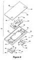
- FIG. 6is an enlarged, exploded perspective side view of the cover of the battery of FIG. 1 , including the outer portion, the inner portion, the circuit board, and the two terminal assemblies;
- FIG. 7is a top plan view of the battery of FIG. 1 , with the cover of the battery removed;
- FIG. 8is a side elevation view of the battery of FIG. 1 , with the cover of the battery removed;
- FIG. 9is a sectional view of the battery of FIG. 1 , without the cover, taken along line 9 — 9 of FIG. 7 ;
- FIG. 10is a top plan view of the battery of FIG. 1 , with the outer portion of the cover removed;
- FIG. 11is a side elevation view of the battery of FIG. 1 , with the outer portion of the cover removed;
- FIG. 12is a sectional view of the battery of FIG. 1 , with the outer portion of the cover removed, taken along line 12 — 12 of FIG. 10 ;
- FIG. 13is an enlarged sectional view of the battery of FIG. 1 , with the outer portion of the cover removed, and as contained within the circled portion 13 of FIG. 12 ;
- FIG. 14is a side elevation view of one of the terminal assemblies of the battery of FIG. 1 ;
- FIG. 15is an end elevation view of the terminal assembly of the battery of FIG. 1 ;
- FIG. 16is a top plan view of one of the terminal assembly of the battery of FIG. 1 ;
- FIG. 17is a sectional view of the terminal assembly of the battery of FIG. 1 , taken along line 17 — 17 of FIG. 16 .
- the present disclosureprovides a battery 10 including a battery post cover 12 having terminal assemblies 14 for measuring electrical energy passing to and from posts 16 of the battery 10 .
- the battery 10is generally similar to typical lead-acid 12 Volt and 36 Volt batteries for use in powering vehicles, such as trucks, automobiles and motorcycles. It should be understood, however, that the present disclosure can be used with many different types of batteries other than lead-acid batteries, such as nickel metal hydride, lithium ion, and lithium polymer batteries.
- the battery 10includes a plastic casing 18 having an open top 20 and cell dividers 22 separating fuel cells 24 .
- Each fuel cell 24contains positive and negative lead plates separated by non-conductive sheets and immersed in an acid electrolyte.
- the battery 10also includes positive lead straps 26 connecting the positive plates and negative lead straps 26 connecting the negative plates.
- the positive lead post 16is connected to the positive plates, while the negative lead post 16 is connected to the negative plates. Both posts 16 extend out of the open top 20 of the case 18 .
- each terminal assembly 14includes an electrically conductive collar 28 having an inner surface 30 for contacting the battery post 16 , and an electrically conductive terminal 32 for receiving a connector (not shown) of a load, such as a cable clamp of a vehicle.
- Each assembly 14also includes an electrically conductive shunt resistor 34 having a known resistance “R” extending between outer surfaces of the collar 28 and the terminal 32 .
- Current flow “I” from the battery post 16travels through the resistor 34 from the collar 28 to the terminal 32 and current flow to the battery post 16 travels through the resistor 34 from the terminal 32 to the collar 28 .
- Leads 36extend from the outer surfaces of the collar 28 and the terminal 32 for measuring a voltage drop “v” across the resistor 34 .
- the leads 36can include threaded connectors 38 , as shown.
- the known resistance “R” of the resistor 34is calculated by multiplying the ratio of length of the resistor 34 divided by the cross sectional area of the resistor 34 by the resistivity of the material that the resistor 34 is made of.
- the material from which the terminal assembly 32 is madecan be lead or a non-lead material, as long as the resistance “R” of the resistor 34 is precisely known for purposes of determining current flow “I”.
- Other conductive materials, such as copper, brass and bronzecan alternatively be used, the material selection is based on the galvanic compatibility of the resistor 34 material with the electrochemical system being employed.
- the resistor 34can be made from commercially available alloy materials having a very low temperature coefficient of resistivity, such as Manganin, to reduce the effects of temperature variation when determining current flow “I”.
- the resistor 34can be formed of powdered metal, stamped, machined, cast, or forged.
- the resistor 34can also be insert cast with the collar 28 and the terminal 32 if the resistor 34 is made of different materials than the collar 28 and the terminal 32 .
- the collar 28 and the terminal 32can be plated or dipped in silver, gold, platinum or their alloys to provide a non-corrosive surface, and further dipped or coated with tin to provide better attachment between the lead battery post and plated collar 28 .
- the inner surface 30 of the collar 28is secured to the battery post 16 , as shown best in FIG. 13 , with lead solder 40 for example, to provide an electrical connection and to prevent electrolyte from leaking from the battery 10 .
- the resistor 34is configured for use with a typical lead-acid vehicle battery 10 to measure currents between 0.5 amperes and 1000 amperes, with the resistor 34 being provided with a known resistance “R” of between about 50 microOhm and about 200 microOhm. Preferably, the resistor 34 is provided with a known resistance “R” of about 150 microOhm. The resistance value, of course, is determined based on a trade-off between current measurement accuracy and power dissipation at high current.
- the battery post cover 12is made of a suitably rigid and durable plastic and includes a first surface 42 having two post ports 44 , a second surface 46 having two terminal ports 48 , and a substantially closed chamber 50 receiving a circuit board 52 .
- the terminal assemblies 14are received within the cover 12 with the terminals 32 extending through the terminal ports 48 , the collars 28 positioned within the post ports 44 , and the leads 36 extending into the closed chamber 50 of the cover.
- the threaded connectors 38 of the leads 36are electrically connected to lands of the circuit board 52 with screws 54 , for example.
- a two-piece cover 12is employed for ease of manufacture, with the terminal assemblies 14 insert molded to an inner portion 56 of the cover.
- the inner portion 56is secured to the battery case 18 , through ultrasonic welding for example, such that the open top 20 of the case 18 is sealed shut in a fluid-tight manner.
- an outer portion 58 of the cover 12is secured to the inner portion 56 to secure and protect the circuit board 52 within the cover.
- the cover 12can alternatively be formed as a single piece with the terminal assemblies 14 and the circuit board 52 insert molded therein, or can be constructed from more than two pieces.
- the circuit board 52has arranged and mounted thereon an electrical circuit including components such as a volt meter connected to the leads 36 of at least one of the terminal assemblies 14 for measuring the voltage drops “v” across the resistors 34 .
- the electrical circuitalso includes a memory storing the known resistance “R” of the resistors 34 and a processor programmed to receive the measured voltage drop “v” from the volt meter, retrieve the known resistance “R” from the memory, and calculate current flow “I” through the resistors 34 based on the measured voltage drop “v” and the known resistance “R”.
- circuitscan include an analog-to-digital converter for converting an analog signal from the volt meter to a digital signal for the computer, an indicator such as an LED, and an input/output circuit for connecting the computer to a remote device such as a display screen mounted on the dashboard of a vehicle, or a personal computer with a keyboard, mouse and other user input devices.
- a circuit for use on the circuit board 52is the PS3180 SmartShuntTM Battery 10 Monitor available from the assignee of the present disclosure, PowerSmart, Inc. of Needham, Mass. (www.powersmart.com).
- the circuit board 52can be provided with a thermometer, such as a solid state silicon thermistor, for measuring an actual temperature of the resistors 34 .
- a thermometersuch as a solid state silicon thermistor
- the memory of the circuitalso stores a temperature coefficient of resistivity for the resistor 34
- the processoris further programmed to receive the actual temperature from the thermometer, retrieve the temperature coefficient of resistivity from the memory, calculate an actual resistance of the resistor 34 based on the known resistance “R” (at a ideal temperature), the temperature coefficient of resistivity, and the actual temperature.
- the processoris also programmed to calculate actual current flow through the resistor 34 based on the measured voltage drop and the actual resistance.
- the circuit board 52is preferably also provided with a clock and the processor is programmed to calculate the total charge of the battery 10 based on the current flow “I” and the charge time (when current is provided to the battery 10 ) or the drain time (when current is taken from the battery 10 ).
- the present disclosureaccordingly, provides a new and improved battery 10 including terminal assemblies 14 for monitoring the terminal voltage, the flow of current into and out of the battery 10 and means to mechanically and electrically integrate electronic circuitry for the measure and analysis of battery voltage and current.
- the battery 10is simple in design, relatively inexpensive and capable of manufacture in high volumes. Certain modifications and improvements will occur to those skilled in the art upon a reading of the foregoing description.
- the outer surfaces of the terminals 32can include channels for dissipating heat.
- the battery post cover 12 disclosed hereincan be modified so as able to be retrofit onto the covers of existing batteries.
- the battery post cover 12can also be modified so as to include a single terminal assembly 14 for connection to either a positive or negative post 16 of a battery 10 .
- the circuit board 52 of the battery post cover 12can be provided with additional features and abilities.
Landscapes
- Engineering & Computer Science (AREA)
- Chemical & Material Sciences (AREA)
- Chemical Kinetics & Catalysis (AREA)
- Electrochemistry (AREA)
- General Chemical & Material Sciences (AREA)
- Manufacturing & Machinery (AREA)
- Microelectronics & Electronic Packaging (AREA)
- Power Engineering (AREA)
- Secondary Cells (AREA)
- Connection Of Batteries Or Terminals (AREA)
Abstract
Description
Claims (15)
Priority Applications (2)
| Application Number | Priority Date | Filing Date | Title |
|---|---|---|---|
| US10/419,600US7012404B2 (en) | 2001-04-06 | 2003-04-21 | Battery cover assembly having integrated battery condition monitoring |
| US10/853,983US7205746B2 (en) | 2001-04-06 | 2004-05-25 | Battery cover assembly having integrated battery condition monitoring |
Applications Claiming Priority (3)
| Application Number | Priority Date | Filing Date | Title |
|---|---|---|---|
| US28213301P | 2001-04-06 | 2001-04-06 | |
| US10/010,693US6628102B2 (en) | 2001-04-06 | 2001-12-05 | Current measuring terminal assembly for a battery |
| US10/419,600US7012404B2 (en) | 2001-04-06 | 2003-04-21 | Battery cover assembly having integrated battery condition monitoring |
Related Parent Applications (1)
| Application Number | Title | Priority Date | Filing Date |
|---|---|---|---|
| US10/010,693ContinuationUS6628102B2 (en) | 2001-04-06 | 2001-12-05 | Current measuring terminal assembly for a battery |
Related Child Applications (1)
| Application Number | Title | Priority Date | Filing Date |
|---|---|---|---|
| US10/853,983Continuation-In-PartUS7205746B2 (en) | 2001-04-06 | 2004-05-25 | Battery cover assembly having integrated battery condition monitoring |
Publications (2)
| Publication Number | Publication Date |
|---|---|
| US20040012396A1 US20040012396A1 (en) | 2004-01-22 |
| US7012404B2true US7012404B2 (en) | 2006-03-14 |
Family
ID=26681486
Family Applications (2)
| Application Number | Title | Priority Date | Filing Date |
|---|---|---|---|
| US10/010,693Expired - LifetimeUS6628102B2 (en) | 2001-04-06 | 2001-12-05 | Current measuring terminal assembly for a battery |
| US10/419,600Expired - LifetimeUS7012404B2 (en) | 2001-04-06 | 2003-04-21 | Battery cover assembly having integrated battery condition monitoring |
Family Applications Before (1)
| Application Number | Title | Priority Date | Filing Date |
|---|---|---|---|
| US10/010,693Expired - LifetimeUS6628102B2 (en) | 2001-04-06 | 2001-12-05 | Current measuring terminal assembly for a battery |
Country Status (3)
| Country | Link |
|---|---|
| US (2) | US6628102B2 (en) |
| EP (2) | EP2256900B1 (en) |
| WO (1) | WO2002082617A1 (en) |
Cited By (4)
| Publication number | Priority date | Publication date | Assignee | Title |
|---|---|---|---|---|
| US20070194747A1 (en)* | 2006-02-17 | 2007-08-23 | Lear Corporation | Energy management system for a vehicle |
| US20100019733A1 (en)* | 2008-07-23 | 2010-01-28 | Lear Corporation | Battery monitoring system |
| US10468654B2 (en) | 2013-09-06 | 2019-11-05 | Cps Technology Holdings Llc | Battery module printed circuit board assembly system and method |
| US10541396B2 (en)* | 2011-06-01 | 2020-01-21 | Elringklinger Ag | Conduit system for connecting a plurality |
Families Citing this family (57)
| Publication number | Priority date | Publication date | Assignee | Title |
|---|---|---|---|---|
| US6628102B2 (en) | 2001-04-06 | 2003-09-30 | Microchip Technology Inc. | Current measuring terminal assembly for a battery |
| US7205746B2 (en)* | 2001-04-06 | 2007-04-17 | Microchip Technology Inc. | Battery cover assembly having integrated battery condition monitoring |
| US20030040873A1 (en)* | 2001-08-07 | 2003-02-27 | Vehicle Enhancement Systems, Inc. | Systems and methods for monitoring and storing performance and maintenace data related to an electrical component |
| ITMI20032599A1 (en)* | 2003-12-24 | 2005-06-25 | Italiana Accumulatori Moto Carri Montecch Fab | MODULAR AND MODULAR POWER STATION |
| US20060105263A1 (en)* | 2004-11-16 | 2006-05-18 | Xerox Corporation | Toner composition |
| KR100696685B1 (en)* | 2005-05-16 | 2007-03-20 | 삼성에스디아이 주식회사 | Secondary battery module |
| US7524602B2 (en)* | 2005-06-20 | 2009-04-28 | Xerox Corporation | Low molecular weight latex and toner compositions comprising the same |
| US7686939B2 (en)* | 2005-11-14 | 2010-03-30 | Xerox Corporation | Crystalline wax |
| US7749670B2 (en)* | 2005-11-14 | 2010-07-06 | Xerox Corporation | Toner having crystalline wax |
| US7662272B2 (en) | 2005-11-14 | 2010-02-16 | Xerox Corporation | Crystalline wax |
| US7910275B2 (en)* | 2005-11-14 | 2011-03-22 | Xerox Corporation | Toner having crystalline wax |
| US7553596B2 (en) | 2005-11-14 | 2009-06-30 | Xerox Corporation | Toner having crystalline wax |
| US7385828B2 (en)* | 2006-01-27 | 2008-06-10 | Delphi Technologies, Inc. | Electronic shunt resistor assembly |
| US20090305101A1 (en)* | 2006-04-28 | 2009-12-10 | Werner Belschner | Fuel Cell Apparatus Having a Current Sensor and a Current Sensor for a Fuel Cell Apparatus |
| US7381101B2 (en)* | 2006-08-25 | 2008-06-03 | Lear Corporation | Battery post connector |
| US7500888B2 (en)* | 2007-02-08 | 2009-03-10 | Lear Corporation | Battery post connector |
| US8278018B2 (en)* | 2007-03-14 | 2012-10-02 | Xerox Corporation | Process for producing dry ink colorants that will reduce metamerism |
| US8476864B2 (en)* | 2007-06-13 | 2013-07-02 | Lear Corporation | Battery monitoring system |
| US20090168290A1 (en)* | 2007-12-28 | 2009-07-02 | Patrick Dale Riedlinger | Battery clip wtih integrated microprocessor reset switch and method of operating |
| DE102008054452A1 (en) | 2008-12-10 | 2010-06-17 | Robert Bosch Gmbh | Polklemmenanordnung |
| US8076048B2 (en)* | 2009-03-17 | 2011-12-13 | Xerox Corporation | Toner having polyester resin |
| US8124307B2 (en) | 2009-03-30 | 2012-02-28 | Xerox Corporation | Toner having polyester resin |
| US8431306B2 (en) | 2010-03-09 | 2013-04-30 | Xerox Corporation | Polyester resin containing toner |
| WO2012078727A2 (en) | 2010-12-07 | 2012-06-14 | Allison Transmission, Inc. | Energy storage system for hybrid electric vehicle |
| DE102011102211A1 (en)* | 2011-05-21 | 2012-11-22 | Otto Diez Elektromaschinenbau | Device and method for monitoring operating data of a battery system |
| US9472797B2 (en)* | 2011-05-25 | 2016-10-18 | Samsung Sdi Co., Ltd. | Battery pack |
| JP5825904B2 (en)* | 2011-07-27 | 2015-12-02 | 矢崎総業株式会社 | Battery status notification unit, bus bar module, assembled battery, and battery status monitoring system |
| US9559509B2 (en)* | 2011-10-13 | 2017-01-31 | Keihin Corporation | Power supply control device |
| KR101658025B1 (en)* | 2011-11-02 | 2016-09-21 | 삼성에스디아이 주식회사 | Secondary battery |
| US8574803B2 (en) | 2011-12-23 | 2013-11-05 | Xerox Corporation | Toner compositions of biodegradable amorphous polyester resins |
| JP6136168B2 (en)* | 2012-09-28 | 2017-05-31 | 株式会社Gsユアサ | Assembled battery |
| US9478787B2 (en)* | 2012-11-19 | 2016-10-25 | Aquion Energy Inc. | Device and method for electrochemical device electrical interconnection |
| US20140152313A1 (en)* | 2012-12-03 | 2014-06-05 | Isabellenhuette Heusler Gmbh & Co. Kg | Battery sensor |
| DE102012222866A1 (en)* | 2012-12-12 | 2014-06-26 | Robert Bosch Gmbh | Cover for battery module of battery system for use in motor vehicle, has electrically conductive contact elements electrically conductively contacted with electric poles of battery cell during arrangement of covering body on module |
| KR102025947B1 (en)* | 2012-12-27 | 2019-09-26 | 타이코에이엠피 주식회사 | Protection circuit module and battery module including the same |
| DE102013210128A1 (en)* | 2013-03-05 | 2014-09-11 | Continental Automotive Gmbh | Integrally formed current sensor device |
| DE102013203799A1 (en)* | 2013-03-06 | 2014-09-11 | Robert Bosch Gmbh | Battery cell housing with integrated electronics |
| JP5610012B2 (en) | 2013-03-08 | 2014-10-22 | 株式会社豊田自動織機 | Battery module |
| JP6086315B2 (en) | 2013-03-19 | 2017-03-01 | 株式会社Gsユアサ | Power storage device |
| US9328260B2 (en) | 2014-01-15 | 2016-05-03 | Xerox Corporation | Polyester processes |
| US9740124B2 (en) | 2015-05-25 | 2017-08-22 | Xerox Corporation | Toner compositions and processes |
| US9692245B2 (en)* | 2015-08-31 | 2017-06-27 | General Electric Company | Battery management system and power connector |
| GB2545699A (en)* | 2015-12-22 | 2017-06-28 | Poweroasis Ltd | Smart lead acid battery module |
| US10649355B2 (en) | 2016-07-20 | 2020-05-12 | Xerox Corporation | Method of making a polymer composite |
| US10315409B2 (en) | 2016-07-20 | 2019-06-11 | Xerox Corporation | Method of selective laser sintering |
| CN106526093B (en)* | 2016-12-27 | 2018-10-09 | 安徽理士电源技术有限公司 | A kind of lead-acid accumulator through-wall welding effect detection diaphragm capsule |
| TWI619290B (en)* | 2017-04-26 | 2018-03-21 | Zhang Nai Wen | Packaging method and structure of lead acid battery |
| JP2018189384A (en)* | 2017-04-28 | 2018-11-29 | 株式会社Gsユアサ | Current detection device, management device, engine starting battery |
| US10615395B2 (en)* | 2017-05-10 | 2020-04-07 | Apple Inc. | Battery cap with cut-out sections |
| CN109841909A (en)* | 2017-11-27 | 2019-06-04 | 广西明福科技有限公司 | One kind having durability and electricity early warning lead storage battery |
| EP3762983A1 (en) | 2018-03-05 | 2021-01-13 | CPS Technology Holdings LLC | Cap for battery terminal |
| WO2019173366A1 (en) | 2018-03-05 | 2019-09-12 | Cps Technology Holdings Llc | Battery terminal |
| DE102018217149A1 (en)* | 2018-10-08 | 2020-04-09 | Robert Bosch Gmbh | Electrochemical energy storage |
| US10667423B2 (en)* | 2018-10-26 | 2020-05-26 | Dell Products L.P. | Connector cooling and status indicator system |
| CN109391008B (en)* | 2018-11-20 | 2024-12-31 | 漳州高新区远见产业技术研究有限公司 | A mobile phone lithium battery with overcharge prevention function |
| CN210628444U (en)* | 2019-11-25 | 2020-05-26 | 宁德时代新能源科技股份有限公司 | Battery modules, battery packs, and vehicles |
| CN116706408B (en)* | 2023-08-07 | 2023-11-07 | 风帆(扬州)有限责任公司 | Energy storage lithium battery convenient to overhaul and maintain |
Citations (72)
| Publication number | Priority date | Publication date | Assignee | Title |
|---|---|---|---|---|
| US3660759A (en) | 1970-03-19 | 1972-05-02 | Kal Equip Co | Meter connection adapter for automobile electrical system tester including diode and shorting switch therefor |
| US4021718A (en) | 1975-08-21 | 1977-05-03 | General Electric Company | Battery monitoring apparatus |
| US4045721A (en) | 1974-12-30 | 1977-08-30 | Swain William H | Electro-chemical concentration transducer and its use to measure and control acid strength and storage battery charge |
| US4081693A (en)* | 1975-07-18 | 1978-03-28 | Stone Gordon R | Vehicular propulsion system |
| US4180770A (en) | 1978-03-01 | 1979-12-25 | Anderson Power Products, Inc. | Method and apparatus for determining the capacity of lead acid storage batteries |
| US4193025A (en) | 1977-12-23 | 1980-03-11 | Globe-Union, Inc. | Automatic battery analyzer |
| US4349775A (en) | 1981-01-02 | 1982-09-14 | Exxon Research & Engineering Co. | Temperature compensated voltage regulator for photovoltaic charging systems |
| US4396880A (en) | 1981-06-05 | 1983-08-02 | Firing Circuits Inc. | Method and apparatus for charging a battery |
| US4460870A (en) | 1981-07-23 | 1984-07-17 | Curtis Instruments, Inc. | Quiescent voltage sampling battery state of charge meter |
| US4470654A (en)* | 1982-04-20 | 1984-09-11 | Burndy Corporation | Electrical cable connector |
| US4558281A (en) | 1982-06-12 | 1985-12-10 | Lucas Industries | Battery state of charge evaluator |
| US4564798A (en) | 1982-10-06 | 1986-01-14 | Escutcheon Associates | Battery performance control |
| US4583036A (en) | 1982-06-11 | 1986-04-15 | Mitsubishi Denki Kabushiki Kaisha | Charging system diagnostic device |
| US4629964A (en) | 1983-09-28 | 1986-12-16 | Ball Newton E | Battery power source |
| US4678998A (en) | 1985-01-25 | 1987-07-07 | Nissan Motor Company, Limited | Battery condition monitor and monitoring method |
| US4709202A (en) | 1982-06-07 | 1987-11-24 | Norand Corporation | Battery powered system |
| US4876513A (en) | 1988-12-05 | 1989-10-24 | Globe-Union Inc. | Dynamic state-of-charge indicator for a battery and method thereof |
| US4924176A (en)* | 1988-02-22 | 1990-05-08 | Tremblay Alfred U | Polarity indicator for vehicle battery |
| US4937528A (en) | 1988-10-14 | 1990-06-26 | Allied-Signal Inc. | Method for monitoring automotive battery status |
| US4947123A (en) | 1987-11-30 | 1990-08-07 | Aisin Aw Co., Ltd. | Battery state monitoring apparatus |
| US4968942A (en) | 1988-10-14 | 1990-11-06 | Allied-Signal Inc. | Method for monitoring aircraft battery status |
| US5047961A (en) | 1988-05-31 | 1991-09-10 | Simonsen Bent P | Automatic battery monitoring system |
| US5049803A (en) | 1989-05-10 | 1991-09-17 | Allied-Signal Inc. | Method and apparatus for charging and testing batteries |
| US5132626A (en) | 1989-05-31 | 1992-07-21 | Amoco Corporation | Electrolytic storage cell monitoring system |
| US5160880A (en) | 1989-05-10 | 1992-11-03 | Allied-Signal Inc. | Method and apparatus for charging and testing batteries |
| US5191291A (en) | 1991-04-30 | 1993-03-02 | George Taylor | Method and apparatus for determining the performance capabilities of secondary batteries |
| US5250904A (en) | 1991-08-08 | 1993-10-05 | Advanced Power Technology Inc. | Device for predicting imminent failure of a stationary lead acid battery in a float mode |
| US5281919A (en) | 1988-10-14 | 1994-01-25 | Alliedsignal Inc. | Automotive battery status monitor |
| US5321627A (en) | 1992-03-11 | 1994-06-14 | Globe-Union, Inc. | Battery monitor and method for providing operating parameters |
| US5321347A (en) | 1992-04-09 | 1994-06-14 | Chien Chih Chien | Battery charger device and method |
| US5339018A (en) | 1989-06-30 | 1994-08-16 | Analog Devices, Inc. | Integrated circuit monitor for storage battery voltage and temperature |
| US5345163A (en) | 1991-06-05 | 1994-09-06 | Battery Master Inc. | Battery monitoring system |
| US5432429A (en) | 1990-10-23 | 1995-07-11 | Benchmarq Microelectronics, Inc. | System for charging/monitoring batteries for a microprocessor based system |
| US5469043A (en) | 1992-10-13 | 1995-11-21 | Gnb Battery Technologies Inc. | Method for optimizing the charging of lead-acid batteries and an interactive charger |
| US5541489A (en) | 1994-12-15 | 1996-07-30 | Intel Corporation | Smart battery power availability feature based on battery-specific characteristics |
| US5546317A (en) | 1993-05-06 | 1996-08-13 | Alcatel Alsthom Compagnine Generale D'electricite | System for recognizing and managing electrochemical cells |
| US5550475A (en) | 1995-04-11 | 1996-08-27 | Shafer; Timothy M. | Programmable battery charge indicator |
| US5565759A (en) | 1994-12-15 | 1996-10-15 | Intel Corporation | Smart battery providing battery life and recharge time prediction |
| US5572110A (en) | 1994-12-15 | 1996-11-05 | Intel Corporation | Smart battery charger system |
| US5598088A (en) | 1993-11-19 | 1997-01-28 | Robert Bosch Gmbh | Method for determining the charge state of a battery, in particular a vehicle starter battery |
| US5600230A (en) | 1994-12-15 | 1997-02-04 | Intel Corporation | Smart battery providing programmable remaining capacity and run-time alarms based on battery-specific characteristics |
| US5617007A (en) | 1994-08-17 | 1997-04-01 | International Business Machines Corporation | Battery charging method and apparatus using current control |
| US5627453A (en) | 1995-01-11 | 1997-05-06 | Dell Usa, L.P. | Smart battery odometer |
| US5629680A (en)* | 1995-12-11 | 1997-05-13 | Makhija; Surender K. | Vehicle current drain tester with memory saver |
| US5631540A (en) | 1994-11-23 | 1997-05-20 | Lucent Technologies Inc. | Method and apparatus for predicting the remaining capacity and reserve time of a battery on discharge |
| US5635820A (en) | 1994-06-16 | 1997-06-03 | Hyundai Motor Company | Battery charging control device and method for accurately detecting a charging end state |
| US5652069A (en)* | 1994-12-02 | 1997-07-29 | Nippon Soken Inc. | Battery power monitoring apparatus for vehicle |
| US5656920A (en) | 1992-10-13 | 1997-08-12 | Gnb Battery Technologies, Inc. | Method and apparatus for charging a lead-acid battery |
| US5659240A (en) | 1995-02-16 | 1997-08-19 | General Electric Company | Intelligent battery charger for electric drive system batteries |
| US5670863A (en) | 1995-02-07 | 1997-09-23 | Benchmarq Microelectronics, Inc. | Lead acid charger with ratioed time-out periods and current pulse mode of operation |
| US5708348A (en) | 1995-11-20 | 1998-01-13 | Warren Johnson | Method and apparatus for monitoring battery voltage |
| US5710503A (en) | 1996-02-01 | 1998-01-20 | Aims Systems, Inc. | On-line battery monitoring system with defective cell detection capability |
| US5710506A (en) | 1995-02-07 | 1998-01-20 | Benchmarq Microelectronics, Inc. | Lead acid charger |
| US5734252A (en) | 1996-12-20 | 1998-03-31 | Ericsson, Inc. | Method and apparatus for charging a battery of an electronic device using an intelligent external charger |
| US5739670A (en) | 1996-10-31 | 1998-04-14 | General Motors Corporation | Method for diagnosing battery condition |
| US5808445A (en) | 1995-12-06 | 1998-09-15 | The University Of Virginia Patent Foundation | Method for monitoring remaining battery capacity |
| US5825156A (en) | 1995-10-31 | 1998-10-20 | U.S. Philips Corporation | System for monitoring charging/discharging cycles of a rechargeable battery, and host device including a smart battery |
| US5828201A (en) | 1997-10-30 | 1998-10-27 | Lockheed Martin Corporation | Method for maintaining the charge capacity of traction battery modules of a hybrid electric vehicle |
| US5841284A (en) | 1994-11-11 | 1998-11-24 | Fujitsu Limited | Apparatus for monitoring power of battery to supply electric power to load |
| US5889382A (en) | 1996-07-06 | 1999-03-30 | Samsung Electronics Co., Ltd. | Charging device for commonly charging various kinds of battery |
| US5903764A (en) | 1997-05-02 | 1999-05-11 | Micro International, Ltd. | Smart battery selector offering power conversion internally within a portable device |
| US5936385A (en) | 1995-10-31 | 1999-08-10 | U.S. Philips Corporation | System monitoring the discharging period of the charging/discharging cycles of a rechargeable battery, and host device including a smart battery |
| US5949219A (en) | 1998-07-24 | 1999-09-07 | The United States Of America As Represented By The United States Department Of Energy | Optical state-of-charge monitor for batteries |
| US5994876A (en) | 1997-10-09 | 1999-11-30 | Abbott Laboratories | Battery capacity measurement circuit |
| US6001506A (en) | 1997-07-30 | 1999-12-14 | Concorde Battery Corporation | Terminal post assembly for lead acid batteries |
| US6285164B1 (en) | 1998-03-31 | 2001-09-04 | Hitachi, Ltd. | Means for detecting the integrated value of current flow, a means for detecting the value of current flow and a battery pack employing those means |
| US6377030B1 (en)* | 1998-07-31 | 2002-04-23 | Canon Kabushiki Kaisha | Method of charging secondary battery by varying current or voltage at an inflection point in a storage region before full charge and device therefor |
| US6399244B1 (en) | 1999-03-29 | 2002-06-04 | Sanyo Electric Co., Ltd. | Hermetically sealed rectangular battery |
| US20020128791A1 (en)* | 2001-02-20 | 2002-09-12 | Min-Yung Chen | Integrated circuit of an electronic thermometer |
| US6507196B2 (en)* | 1998-06-24 | 2003-01-14 | Intra International Ab | Battery having discharge state indication |
| US6573723B2 (en)* | 2000-04-04 | 2003-06-03 | Microchip Technology Inc. | Current measuring apparatus for battery |
| US6628102B2 (en) | 2001-04-06 | 2003-09-30 | Microchip Technology Inc. | Current measuring terminal assembly for a battery |
Family Cites Families (5)
| Publication number | Priority date | Publication date | Assignee | Title |
|---|---|---|---|---|
| DE3532044A1 (en)* | 1985-09-09 | 1987-03-19 | Vdo Schindling | POLE CLAMP |
| US5214407A (en)* | 1991-11-06 | 1993-05-25 | Hewlett-Packard Company | High performance current shunt |
| US6104967A (en)* | 1997-07-25 | 2000-08-15 | 3M Innovative Properties Company | Fault-tolerant battery system employing intra-battery network architecture |
| EP0990167B1 (en)* | 1998-04-17 | 2006-06-07 | AK Systemtechnik AG | Battery measuring terminal |
| DE19961311A1 (en)* | 1999-12-18 | 2001-07-26 | Bayerische Motoren Werke Ag | Battery sensor device, has attachment device, sensor combined into integrated unit; attachment device is connected to single pole and has conventional terminal |
- 2001
- 2001-12-05USUS10/010,693patent/US6628102B2/ennot_activeExpired - Lifetime
- 2002
- 2002-01-23WOPCT/US2002/001755patent/WO2002082617A1/ennot_activeApplication Discontinuation
- 2002-01-23EPEP10177750.6Apatent/EP2256900B1/ennot_activeExpired - Lifetime
- 2002-01-23EPEP02759845.7Apatent/EP1374364B1/ennot_activeExpired - Lifetime
- 2003
- 2003-04-21USUS10/419,600patent/US7012404B2/ennot_activeExpired - Lifetime
Patent Citations (73)
| Publication number | Priority date | Publication date | Assignee | Title |
|---|---|---|---|---|
| US3660759A (en) | 1970-03-19 | 1972-05-02 | Kal Equip Co | Meter connection adapter for automobile electrical system tester including diode and shorting switch therefor |
| US4045721A (en) | 1974-12-30 | 1977-08-30 | Swain William H | Electro-chemical concentration transducer and its use to measure and control acid strength and storage battery charge |
| US4081693A (en)* | 1975-07-18 | 1978-03-28 | Stone Gordon R | Vehicular propulsion system |
| US4021718A (en) | 1975-08-21 | 1977-05-03 | General Electric Company | Battery monitoring apparatus |
| US4193025A (en) | 1977-12-23 | 1980-03-11 | Globe-Union, Inc. | Automatic battery analyzer |
| US4180770A (en) | 1978-03-01 | 1979-12-25 | Anderson Power Products, Inc. | Method and apparatus for determining the capacity of lead acid storage batteries |
| US4349775A (en) | 1981-01-02 | 1982-09-14 | Exxon Research & Engineering Co. | Temperature compensated voltage regulator for photovoltaic charging systems |
| US4396880A (en) | 1981-06-05 | 1983-08-02 | Firing Circuits Inc. | Method and apparatus for charging a battery |
| US4460870A (en) | 1981-07-23 | 1984-07-17 | Curtis Instruments, Inc. | Quiescent voltage sampling battery state of charge meter |
| US4470654A (en)* | 1982-04-20 | 1984-09-11 | Burndy Corporation | Electrical cable connector |
| US4709202A (en) | 1982-06-07 | 1987-11-24 | Norand Corporation | Battery powered system |
| US4583036A (en) | 1982-06-11 | 1986-04-15 | Mitsubishi Denki Kabushiki Kaisha | Charging system diagnostic device |
| US4558281A (en) | 1982-06-12 | 1985-12-10 | Lucas Industries | Battery state of charge evaluator |
| US4564798A (en) | 1982-10-06 | 1986-01-14 | Escutcheon Associates | Battery performance control |
| US4629964A (en) | 1983-09-28 | 1986-12-16 | Ball Newton E | Battery power source |
| US4678998A (en) | 1985-01-25 | 1987-07-07 | Nissan Motor Company, Limited | Battery condition monitor and monitoring method |
| US4947123A (en) | 1987-11-30 | 1990-08-07 | Aisin Aw Co., Ltd. | Battery state monitoring apparatus |
| US4924176A (en)* | 1988-02-22 | 1990-05-08 | Tremblay Alfred U | Polarity indicator for vehicle battery |
| US5047961A (en) | 1988-05-31 | 1991-09-10 | Simonsen Bent P | Automatic battery monitoring system |
| US4968942A (en) | 1988-10-14 | 1990-11-06 | Allied-Signal Inc. | Method for monitoring aircraft battery status |
| US4937528A (en) | 1988-10-14 | 1990-06-26 | Allied-Signal Inc. | Method for monitoring automotive battery status |
| US5281919A (en) | 1988-10-14 | 1994-01-25 | Alliedsignal Inc. | Automotive battery status monitor |
| US4876513A (en) | 1988-12-05 | 1989-10-24 | Globe-Union Inc. | Dynamic state-of-charge indicator for a battery and method thereof |
| US5049803A (en) | 1989-05-10 | 1991-09-17 | Allied-Signal Inc. | Method and apparatus for charging and testing batteries |
| US5160880A (en) | 1989-05-10 | 1992-11-03 | Allied-Signal Inc. | Method and apparatus for charging and testing batteries |
| US5132626A (en) | 1989-05-31 | 1992-07-21 | Amoco Corporation | Electrolytic storage cell monitoring system |
| US5339018A (en) | 1989-06-30 | 1994-08-16 | Analog Devices, Inc. | Integrated circuit monitor for storage battery voltage and temperature |
| US5432429A (en) | 1990-10-23 | 1995-07-11 | Benchmarq Microelectronics, Inc. | System for charging/monitoring batteries for a microprocessor based system |
| US5191291A (en) | 1991-04-30 | 1993-03-02 | George Taylor | Method and apparatus for determining the performance capabilities of secondary batteries |
| US5345163A (en) | 1991-06-05 | 1994-09-06 | Battery Master Inc. | Battery monitoring system |
| US5250904A (en) | 1991-08-08 | 1993-10-05 | Advanced Power Technology Inc. | Device for predicting imminent failure of a stationary lead acid battery in a float mode |
| US5321627A (en) | 1992-03-11 | 1994-06-14 | Globe-Union, Inc. | Battery monitor and method for providing operating parameters |
| US5321347A (en) | 1992-04-09 | 1994-06-14 | Chien Chih Chien | Battery charger device and method |
| US5469043A (en) | 1992-10-13 | 1995-11-21 | Gnb Battery Technologies Inc. | Method for optimizing the charging of lead-acid batteries and an interactive charger |
| US5656920A (en) | 1992-10-13 | 1997-08-12 | Gnb Battery Technologies, Inc. | Method and apparatus for charging a lead-acid battery |
| US5546317A (en) | 1993-05-06 | 1996-08-13 | Alcatel Alsthom Compagnine Generale D'electricite | System for recognizing and managing electrochemical cells |
| US5598088A (en) | 1993-11-19 | 1997-01-28 | Robert Bosch Gmbh | Method for determining the charge state of a battery, in particular a vehicle starter battery |
| US5635820A (en) | 1994-06-16 | 1997-06-03 | Hyundai Motor Company | Battery charging control device and method for accurately detecting a charging end state |
| US5617007A (en) | 1994-08-17 | 1997-04-01 | International Business Machines Corporation | Battery charging method and apparatus using current control |
| US5841284A (en) | 1994-11-11 | 1998-11-24 | Fujitsu Limited | Apparatus for monitoring power of battery to supply electric power to load |
| US5631540A (en) | 1994-11-23 | 1997-05-20 | Lucent Technologies Inc. | Method and apparatus for predicting the remaining capacity and reserve time of a battery on discharge |
| US5652069A (en)* | 1994-12-02 | 1997-07-29 | Nippon Soken Inc. | Battery power monitoring apparatus for vehicle |
| US5565759A (en) | 1994-12-15 | 1996-10-15 | Intel Corporation | Smart battery providing battery life and recharge time prediction |
| US5600230A (en) | 1994-12-15 | 1997-02-04 | Intel Corporation | Smart battery providing programmable remaining capacity and run-time alarms based on battery-specific characteristics |
| US5572110A (en) | 1994-12-15 | 1996-11-05 | Intel Corporation | Smart battery charger system |
| US5541489A (en) | 1994-12-15 | 1996-07-30 | Intel Corporation | Smart battery power availability feature based on battery-specific characteristics |
| US5627453A (en) | 1995-01-11 | 1997-05-06 | Dell Usa, L.P. | Smart battery odometer |
| US5670863A (en) | 1995-02-07 | 1997-09-23 | Benchmarq Microelectronics, Inc. | Lead acid charger with ratioed time-out periods and current pulse mode of operation |
| US5710506A (en) | 1995-02-07 | 1998-01-20 | Benchmarq Microelectronics, Inc. | Lead acid charger |
| US5659240A (en) | 1995-02-16 | 1997-08-19 | General Electric Company | Intelligent battery charger for electric drive system batteries |
| US5550475A (en) | 1995-04-11 | 1996-08-27 | Shafer; Timothy M. | Programmable battery charge indicator |
| US5936385A (en) | 1995-10-31 | 1999-08-10 | U.S. Philips Corporation | System monitoring the discharging period of the charging/discharging cycles of a rechargeable battery, and host device including a smart battery |
| US5825156A (en) | 1995-10-31 | 1998-10-20 | U.S. Philips Corporation | System for monitoring charging/discharging cycles of a rechargeable battery, and host device including a smart battery |
| US5708348A (en) | 1995-11-20 | 1998-01-13 | Warren Johnson | Method and apparatus for monitoring battery voltage |
| US5808445A (en) | 1995-12-06 | 1998-09-15 | The University Of Virginia Patent Foundation | Method for monitoring remaining battery capacity |
| US5629680A (en)* | 1995-12-11 | 1997-05-13 | Makhija; Surender K. | Vehicle current drain tester with memory saver |
| US5710503A (en) | 1996-02-01 | 1998-01-20 | Aims Systems, Inc. | On-line battery monitoring system with defective cell detection capability |
| US5923148A (en) | 1996-02-01 | 1999-07-13 | Aims System, Inc. | On-line battery monitoring system with defective cell detection capability |
| US5889382A (en) | 1996-07-06 | 1999-03-30 | Samsung Electronics Co., Ltd. | Charging device for commonly charging various kinds of battery |
| US5739670A (en) | 1996-10-31 | 1998-04-14 | General Motors Corporation | Method for diagnosing battery condition |
| US5734252A (en) | 1996-12-20 | 1998-03-31 | Ericsson, Inc. | Method and apparatus for charging a battery of an electronic device using an intelligent external charger |
| US5903764A (en) | 1997-05-02 | 1999-05-11 | Micro International, Ltd. | Smart battery selector offering power conversion internally within a portable device |
| US6001506A (en) | 1997-07-30 | 1999-12-14 | Concorde Battery Corporation | Terminal post assembly for lead acid batteries |
| US5994876A (en) | 1997-10-09 | 1999-11-30 | Abbott Laboratories | Battery capacity measurement circuit |
| US5828201A (en) | 1997-10-30 | 1998-10-27 | Lockheed Martin Corporation | Method for maintaining the charge capacity of traction battery modules of a hybrid electric vehicle |
| US6285164B1 (en) | 1998-03-31 | 2001-09-04 | Hitachi, Ltd. | Means for detecting the integrated value of current flow, a means for detecting the value of current flow and a battery pack employing those means |
| US6507196B2 (en)* | 1998-06-24 | 2003-01-14 | Intra International Ab | Battery having discharge state indication |
| US5949219A (en) | 1998-07-24 | 1999-09-07 | The United States Of America As Represented By The United States Department Of Energy | Optical state-of-charge monitor for batteries |
| US6377030B1 (en)* | 1998-07-31 | 2002-04-23 | Canon Kabushiki Kaisha | Method of charging secondary battery by varying current or voltage at an inflection point in a storage region before full charge and device therefor |
| US6399244B1 (en) | 1999-03-29 | 2002-06-04 | Sanyo Electric Co., Ltd. | Hermetically sealed rectangular battery |
| US6573723B2 (en)* | 2000-04-04 | 2003-06-03 | Microchip Technology Inc. | Current measuring apparatus for battery |
| US20020128791A1 (en)* | 2001-02-20 | 2002-09-12 | Min-Yung Chen | Integrated circuit of an electronic thermometer |
| US6628102B2 (en) | 2001-04-06 | 2003-09-30 | Microchip Technology Inc. | Current measuring terminal assembly for a battery |
Non-Patent Citations (2)
| Title |
|---|
| Microchip Technology, Inc., 12V Battery Monitor with LIN Communications Interface, DS21803A, pp. 1-4, Mar. 25, 2003. |
| PowerSmart Product Data, PS3180 SmartShunt TM Battery Monitor, 2000, Rev. A, pp. 1-2 and 1-6, 2000. |
Cited By (8)
| Publication number | Priority date | Publication date | Assignee | Title |
|---|---|---|---|---|
| US20070194747A1 (en)* | 2006-02-17 | 2007-08-23 | Lear Corporation | Energy management system for a vehicle |
| US7688022B2 (en) | 2006-02-17 | 2010-03-30 | Lear Corporation | Energy management system for a vehicle |
| US20100019733A1 (en)* | 2008-07-23 | 2010-01-28 | Lear Corporation | Battery monitoring system |
| US8305034B2 (en) | 2008-07-23 | 2012-11-06 | Lear Corporation | Battery monitoring system |
| US10541396B2 (en)* | 2011-06-01 | 2020-01-21 | Elringklinger Ag | Conduit system for connecting a plurality |
| US10468654B2 (en) | 2013-09-06 | 2019-11-05 | Cps Technology Holdings Llc | Battery module printed circuit board assembly system and method |
| US11628728B2 (en) | 2013-09-06 | 2023-04-18 | Cps Technology Holdings Llc | Battery module printed circuit board assembly system and method |
| US12208694B2 (en) | 2013-09-06 | 2025-01-28 | Cps Technology Holdings Llc | Battery module printed circuit board assembly system and method |
Also Published As
| Publication number | Publication date |
|---|---|
| EP2256900B1 (en) | 2018-10-03 |
| US20020180405A1 (en) | 2002-12-05 |
| US20040012396A1 (en) | 2004-01-22 |
| EP2256900A1 (en) | 2010-12-01 |
| US6628102B2 (en) | 2003-09-30 |
| WO2002082617A1 (en) | 2002-10-17 |
| EP1374364B1 (en) | 2018-07-11 |
| EP1374364A4 (en) | 2008-05-14 |
| EP1374364A1 (en) | 2004-01-02 |
Similar Documents
| Publication | Publication Date | Title |
|---|---|---|
| US7012404B2 (en) | Battery cover assembly having integrated battery condition monitoring | |
| US7205746B2 (en) | Battery cover assembly having integrated battery condition monitoring | |
| US6304062B1 (en) | Shunt resistance device for monitoring battery state of charge | |
| EP1807710B1 (en) | Kelvin connector including temperature sensor | |
| US6507196B2 (en) | Battery having discharge state indication | |
| US6573723B2 (en) | Current measuring apparatus for battery | |
| KR102512068B1 (en) | Battery module with thermocouple unit | |
| KR20080084238A (en) | Protective Circuit Board for Secondary Battery and Secondary Battery Using the Same | |
| CN112858933B (en) | Sensor systems for battery modules | |
| US10613147B2 (en) | Current shunt for measuring battery current | |
| US5304433A (en) | Capacity indicator for lead-acid batteries | |
| CN109863624A (en) | Bus bar for battery system and battery system having the same | |
| JPH05307950A (en) | Battery pack | |
| EP1876461B1 (en) | Current measuring apparatus for battery | |
| EP3823076B1 (en) | Sensor system for a battery module | |
| LV14799B (en) | Battery with composite contact wire | |
| JPH08203568A (en) | Secondary battery pack | |
| CN112436178A (en) | Lithium ion battery, third electrode testing method thereof, battery module and automobile | |
| JPS63157079A (en) | Charging and discharging current detector for battery for internal combustion engine |
Legal Events
| Date | Code | Title | Description |
|---|---|---|---|
| STCF | Information on status: patent grant | Free format text:PATENTED CASE | |
| FPAY | Fee payment | Year of fee payment:4 | |
| FPAY | Fee payment | Year of fee payment:8 | |
| AS | Assignment | Owner name:JPMORGAN CHASE BANK, N.A., AS ADMINISTRATIVE AGENT, ILLINOIS Free format text:SECURITY INTEREST;ASSIGNOR:MICROCHIP TECHNOLOGY INCORPORATED;REEL/FRAME:041675/0617 Effective date:20170208 Owner name:JPMORGAN CHASE BANK, N.A., AS ADMINISTRATIVE AGENT Free format text:SECURITY INTEREST;ASSIGNOR:MICROCHIP TECHNOLOGY INCORPORATED;REEL/FRAME:041675/0617 Effective date:20170208 | |
| MAFP | Maintenance fee payment | Free format text:PAYMENT OF MAINTENANCE FEE, 12TH YEAR, LARGE ENTITY (ORIGINAL EVENT CODE: M1553) Year of fee payment:12 | |
| AS | Assignment | Owner name:JPMORGAN CHASE BANK, N.A., AS ADMINISTRATIVE AGENT, ILLINOIS Free format text:SECURITY INTEREST;ASSIGNORS:MICROCHIP TECHNOLOGY INCORPORATED;SILICON STORAGE TECHNOLOGY, INC.;ATMEL CORPORATION;AND OTHERS;REEL/FRAME:046426/0001 Effective date:20180529 Owner name:JPMORGAN CHASE BANK, N.A., AS ADMINISTRATIVE AGENT Free format text:SECURITY INTEREST;ASSIGNORS:MICROCHIP TECHNOLOGY INCORPORATED;SILICON STORAGE TECHNOLOGY, INC.;ATMEL CORPORATION;AND OTHERS;REEL/FRAME:046426/0001 Effective date:20180529 | |
| AS | Assignment | Owner name:WELLS FARGO BANK, NATIONAL ASSOCIATION, AS NOTES COLLATERAL AGENT, CALIFORNIA Free format text:SECURITY INTEREST;ASSIGNORS:MICROCHIP TECHNOLOGY INCORPORATED;SILICON STORAGE TECHNOLOGY, INC.;ATMEL CORPORATION;AND OTHERS;REEL/FRAME:047103/0206 Effective date:20180914 Owner name:WELLS FARGO BANK, NATIONAL ASSOCIATION, AS NOTES C Free format text:SECURITY INTEREST;ASSIGNORS:MICROCHIP TECHNOLOGY INCORPORATED;SILICON STORAGE TECHNOLOGY, INC.;ATMEL CORPORATION;AND OTHERS;REEL/FRAME:047103/0206 Effective date:20180914 | |
| AS | Assignment | Owner name:JPMORGAN CHASE BANK, N.A., AS ADMINISTRATIVE AGENT, DELAWARE Free format text:SECURITY INTEREST;ASSIGNORS:MICROCHIP TECHNOLOGY INC.;SILICON STORAGE TECHNOLOGY, INC.;ATMEL CORPORATION;AND OTHERS;REEL/FRAME:053311/0305 Effective date:20200327 | |
| AS | Assignment | Owner name:MICROCHIP TECHNOLOGY INC., ARIZONA Free format text:RELEASE BY SECURED PARTY;ASSIGNOR:JPMORGAN CHASE BANK, N.A, AS ADMINISTRATIVE AGENT;REEL/FRAME:053466/0011 Effective date:20200529 Owner name:SILICON STORAGE TECHNOLOGY, INC., ARIZONA Free format text:RELEASE BY SECURED PARTY;ASSIGNOR:JPMORGAN CHASE BANK, N.A, AS ADMINISTRATIVE AGENT;REEL/FRAME:053466/0011 Effective date:20200529 Owner name:MICROSEMI CORPORATION, CALIFORNIA Free format text:RELEASE BY SECURED PARTY;ASSIGNOR:JPMORGAN CHASE BANK, N.A, AS ADMINISTRATIVE AGENT;REEL/FRAME:053466/0011 Effective date:20200529 Owner name:MICROSEMI STORAGE SOLUTIONS, INC., ARIZONA Free format text:RELEASE BY SECURED PARTY;ASSIGNOR:JPMORGAN CHASE BANK, N.A, AS ADMINISTRATIVE AGENT;REEL/FRAME:053466/0011 Effective date:20200529 Owner name:ATMEL CORPORATION, ARIZONA Free format text:RELEASE BY SECURED PARTY;ASSIGNOR:JPMORGAN CHASE BANK, N.A, AS ADMINISTRATIVE AGENT;REEL/FRAME:053466/0011 Effective date:20200529 | |
| AS | Assignment | Owner name:WELLS FARGO BANK, NATIONAL ASSOCIATION, MINNESOTA Free format text:SECURITY INTEREST;ASSIGNORS:MICROCHIP TECHNOLOGY INC.;SILICON STORAGE TECHNOLOGY, INC.;ATMEL CORPORATION;AND OTHERS;REEL/FRAME:053468/0705 Effective date:20200529 | |
| AS | Assignment | Owner name:WELLS FARGO BANK, NATIONAL ASSOCIATION, AS COLLATERAL AGENT, MINNESOTA Free format text:SECURITY INTEREST;ASSIGNORS:MICROCHIP TECHNOLOGY INCORPORATED;SILICON STORAGE TECHNOLOGY, INC.;ATMEL CORPORATION;AND OTHERS;REEL/FRAME:055671/0612 Effective date:20201217 | |
| AS | Assignment | Owner name:WELLS FARGO BANK, NATIONAL ASSOCIATION, AS NOTES COLLATERAL AGENT, MINNESOTA Free format text:SECURITY INTEREST;ASSIGNORS:MICROCHIP TECHNOLOGY INCORPORATED;SILICON STORAGE TECHNOLOGY, INC.;ATMEL CORPORATION;AND OTHERS;REEL/FRAME:057935/0474 Effective date:20210528 | |
| AS | Assignment | Owner name:MICROSEMI STORAGE SOLUTIONS, INC., ARIZONA Free format text:RELEASE BY SECURED PARTY;ASSIGNOR:JPMORGAN CHASE BANK, N.A., AS ADMINISTRATIVE AGENT;REEL/FRAME:059333/0222 Effective date:20220218 Owner name:MICROSEMI CORPORATION, ARIZONA Free format text:RELEASE BY SECURED PARTY;ASSIGNOR:JPMORGAN CHASE BANK, N.A., AS ADMINISTRATIVE AGENT;REEL/FRAME:059333/0222 Effective date:20220218 Owner name:ATMEL CORPORATION, ARIZONA Free format text:RELEASE BY SECURED PARTY;ASSIGNOR:JPMORGAN CHASE BANK, N.A., AS ADMINISTRATIVE AGENT;REEL/FRAME:059333/0222 Effective date:20220218 Owner name:SILICON STORAGE TECHNOLOGY, INC., ARIZONA Free format text:RELEASE BY SECURED PARTY;ASSIGNOR:JPMORGAN CHASE BANK, N.A., AS ADMINISTRATIVE AGENT;REEL/FRAME:059333/0222 Effective date:20220218 Owner name:MICROCHIP TECHNOLOGY INCORPORATED, ARIZONA Free format text:RELEASE BY SECURED PARTY;ASSIGNOR:JPMORGAN CHASE BANK, N.A., AS ADMINISTRATIVE AGENT;REEL/FRAME:059333/0222 Effective date:20220218 | |
| AS | Assignment | Owner name:MICROCHIP TECHNOLOGY INCORPORATED, ARIZONA Free format text:RELEASE BY SECURED PARTY;ASSIGNOR:JPMORGAN CHASE BANK, N.A., AS ADMINISTRATIVE AGENT;REEL/FRAME:059666/0545 Effective date:20220218 | |
| AS | Assignment | Owner name:MICROSEMI STORAGE SOLUTIONS, INC., ARIZONA Free format text:RELEASE BY SECURED PARTY;ASSIGNOR:WELLS FARGO BANK, NATIONAL ASSOCIATION, AS NOTES COLLATERAL AGENT;REEL/FRAME:059358/0001 Effective date:20220228 Owner name:MICROSEMI CORPORATION, ARIZONA Free format text:RELEASE BY SECURED PARTY;ASSIGNOR:WELLS FARGO BANK, NATIONAL ASSOCIATION, AS NOTES COLLATERAL AGENT;REEL/FRAME:059358/0001 Effective date:20220228 Owner name:ATMEL CORPORATION, ARIZONA Free format text:RELEASE BY SECURED PARTY;ASSIGNOR:WELLS FARGO BANK, NATIONAL ASSOCIATION, AS NOTES COLLATERAL AGENT;REEL/FRAME:059358/0001 Effective date:20220228 Owner name:SILICON STORAGE TECHNOLOGY, INC., ARIZONA Free format text:RELEASE BY SECURED PARTY;ASSIGNOR:WELLS FARGO BANK, NATIONAL ASSOCIATION, AS NOTES COLLATERAL AGENT;REEL/FRAME:059358/0001 Effective date:20220228 Owner name:MICROCHIP TECHNOLOGY INCORPORATED, ARIZONA Free format text:RELEASE BY SECURED PARTY;ASSIGNOR:WELLS FARGO BANK, NATIONAL ASSOCIATION, AS NOTES COLLATERAL AGENT;REEL/FRAME:059358/0001 Effective date:20220228 | |
| AS | Assignment | Owner name:MICROSEMI STORAGE SOLUTIONS, INC., ARIZONA Free format text:RELEASE BY SECURED PARTY;ASSIGNOR:WELLS FARGO BANK, NATIONAL ASSOCIATION, AS NOTES COLLATERAL AGENT;REEL/FRAME:059863/0400 Effective date:20220228 Owner name:MICROSEMI CORPORATION, ARIZONA Free format text:RELEASE BY SECURED PARTY;ASSIGNOR:WELLS FARGO BANK, NATIONAL ASSOCIATION, AS NOTES COLLATERAL AGENT;REEL/FRAME:059863/0400 Effective date:20220228 Owner name:ATMEL CORPORATION, ARIZONA Free format text:RELEASE BY SECURED PARTY;ASSIGNOR:WELLS FARGO BANK, NATIONAL ASSOCIATION, AS NOTES COLLATERAL AGENT;REEL/FRAME:059863/0400 Effective date:20220228 Owner name:SILICON STORAGE TECHNOLOGY, INC., ARIZONA Free format text:RELEASE BY SECURED PARTY;ASSIGNOR:WELLS FARGO BANK, NATIONAL ASSOCIATION, AS NOTES COLLATERAL AGENT;REEL/FRAME:059863/0400 Effective date:20220228 Owner name:MICROCHIP TECHNOLOGY INCORPORATED, ARIZONA Free format text:RELEASE BY SECURED PARTY;ASSIGNOR:WELLS FARGO BANK, NATIONAL ASSOCIATION, AS NOTES COLLATERAL AGENT;REEL/FRAME:059863/0400 Effective date:20220228 | |
| AS | Assignment | Owner name:MICROSEMI STORAGE SOLUTIONS, INC., ARIZONA Free format text:RELEASE BY SECURED PARTY;ASSIGNOR:WELLS FARGO BANK, NATIONAL ASSOCIATION, AS NOTES COLLATERAL AGENT;REEL/FRAME:059363/0001 Effective date:20220228 Owner name:MICROSEMI CORPORATION, ARIZONA Free format text:RELEASE BY SECURED PARTY;ASSIGNOR:WELLS FARGO BANK, NATIONAL ASSOCIATION, AS NOTES COLLATERAL AGENT;REEL/FRAME:059363/0001 Effective date:20220228 Owner name:ATMEL CORPORATION, ARIZONA Free format text:RELEASE BY SECURED PARTY;ASSIGNOR:WELLS FARGO BANK, NATIONAL ASSOCIATION, AS NOTES COLLATERAL AGENT;REEL/FRAME:059363/0001 Effective date:20220228 Owner name:SILICON STORAGE TECHNOLOGY, INC., ARIZONA Free format text:RELEASE BY SECURED PARTY;ASSIGNOR:WELLS FARGO BANK, NATIONAL ASSOCIATION, AS NOTES COLLATERAL AGENT;REEL/FRAME:059363/0001 Effective date:20220228 Owner name:MICROCHIP TECHNOLOGY INCORPORATED, ARIZONA Free format text:RELEASE BY SECURED PARTY;ASSIGNOR:WELLS FARGO BANK, NATIONAL ASSOCIATION, AS NOTES COLLATERAL AGENT;REEL/FRAME:059363/0001 Effective date:20220228 | |
| AS | Assignment | Owner name:MICROSEMI STORAGE SOLUTIONS, INC., ARIZONA Free format text:RELEASE BY SECURED PARTY;ASSIGNOR:WELLS FARGO BANK, NATIONAL ASSOCIATION, AS NOTES COLLATERAL AGENT;REEL/FRAME:060894/0437 Effective date:20220228 Owner name:MICROSEMI CORPORATION, ARIZONA Free format text:RELEASE BY SECURED PARTY;ASSIGNOR:WELLS FARGO BANK, NATIONAL ASSOCIATION, AS NOTES COLLATERAL AGENT;REEL/FRAME:060894/0437 Effective date:20220228 Owner name:ATMEL CORPORATION, ARIZONA Free format text:RELEASE BY SECURED PARTY;ASSIGNOR:WELLS FARGO BANK, NATIONAL ASSOCIATION, AS NOTES COLLATERAL AGENT;REEL/FRAME:060894/0437 Effective date:20220228 Owner name:SILICON STORAGE TECHNOLOGY, INC., ARIZONA Free format text:RELEASE BY SECURED PARTY;ASSIGNOR:WELLS FARGO BANK, NATIONAL ASSOCIATION, AS NOTES COLLATERAL AGENT;REEL/FRAME:060894/0437 Effective date:20220228 Owner name:MICROCHIP TECHNOLOGY INCORPORATED, ARIZONA Free format text:RELEASE BY SECURED PARTY;ASSIGNOR:WELLS FARGO BANK, NATIONAL ASSOCIATION, AS NOTES COLLATERAL AGENT;REEL/FRAME:060894/0437 Effective date:20220228 |