US7012274B2 - Modulation doped thyristor and complementary transistors combination for a monolithic optoelectronic integrated circuit - Google Patents
Modulation doped thyristor and complementary transistors combination for a monolithic optoelectronic integrated circuitDownload PDFInfo
- Publication number
- US7012274B2 US7012274B2US10/469,649US46964903AUS7012274B2US 7012274 B2US7012274 B2US 7012274B2US 46964903 AUS46964903 AUS 46964903AUS 7012274 B2US7012274 B2US 7012274B2
- Authority
- US
- United States
- Prior art keywords
- type
- waveguide
- layer
- semiconductor device
- optical
- Prior art date
- Legal status (The legal status is an assumption and is not a legal conclusion. Google has not performed a legal analysis and makes no representation as to the accuracy of the status listed.)
- Expired - Lifetime
Links
Images


Classifications
- G—PHYSICS
- G02—OPTICS
- G02B—OPTICAL ELEMENTS, SYSTEMS OR APPARATUS
- G02B6/00—Light guides; Structural details of arrangements comprising light guides and other optical elements, e.g. couplings
- G02B6/24—Coupling light guides
- G02B6/26—Optical coupling means
- G02B6/28—Optical coupling means having data bus means, i.e. plural waveguides interconnected and providing an inherently bidirectional system by mixing and splitting signals
- H—ELECTRICITY
- H10—SEMICONDUCTOR DEVICES; ELECTRIC SOLID-STATE DEVICES NOT OTHERWISE PROVIDED FOR
- H10D—INORGANIC ELECTRIC SEMICONDUCTOR DEVICES
- H10D10/00—Bipolar junction transistors [BJT]
- H10D10/80—Heterojunction BJTs
- B—PERFORMING OPERATIONS; TRANSPORTING
- B82—NANOTECHNOLOGY
- B82Y—SPECIFIC USES OR APPLICATIONS OF NANOSTRUCTURES; MEASUREMENT OR ANALYSIS OF NANOSTRUCTURES; MANUFACTURE OR TREATMENT OF NANOSTRUCTURES
- B82Y20/00—Nanooptics, e.g. quantum optics or photonic crystals
- G—PHYSICS
- G02—OPTICS
- G02F—OPTICAL DEVICES OR ARRANGEMENTS FOR THE CONTROL OF LIGHT BY MODIFICATION OF THE OPTICAL PROPERTIES OF THE MEDIA OF THE ELEMENTS INVOLVED THEREIN; NON-LINEAR OPTICS; FREQUENCY-CHANGING OF LIGHT; OPTICAL LOGIC ELEMENTS; OPTICAL ANALOGUE/DIGITAL CONVERTERS
- G02F1/00—Devices or arrangements for the control of the intensity, colour, phase, polarisation or direction of light arriving from an independent light source, e.g. switching, gating or modulating; Non-linear optics
- G02F1/01—Devices or arrangements for the control of the intensity, colour, phase, polarisation or direction of light arriving from an independent light source, e.g. switching, gating or modulating; Non-linear optics for the control of the intensity, phase, polarisation or colour
- G02F1/015—Devices or arrangements for the control of the intensity, colour, phase, polarisation or direction of light arriving from an independent light source, e.g. switching, gating or modulating; Non-linear optics for the control of the intensity, phase, polarisation or colour based on semiconductor elements having potential barriers, e.g. having a PN or PIN junction
- G02F1/025—Devices or arrangements for the control of the intensity, colour, phase, polarisation or direction of light arriving from an independent light source, e.g. switching, gating or modulating; Non-linear optics for the control of the intensity, phase, polarisation or colour based on semiconductor elements having potential barriers, e.g. having a PN or PIN junction in an optical waveguide structure
- H—ELECTRICITY
- H10—SEMICONDUCTOR DEVICES; ELECTRIC SOLID-STATE DEVICES NOT OTHERWISE PROVIDED FOR
- H10D—INORGANIC ELECTRIC SEMICONDUCTOR DEVICES
- H10D10/00—Bipolar junction transistors [BJT]
- H10D10/80—Heterojunction BJTs
- H10D10/821—Vertical heterojunction BJTs
- H—ELECTRICITY
- H10—SEMICONDUCTOR DEVICES; ELECTRIC SOLID-STATE DEVICES NOT OTHERWISE PROVIDED FOR
- H10D—INORGANIC ELECTRIC SEMICONDUCTOR DEVICES
- H10D18/00—Thyristors
- H—ELECTRICITY
- H10—SEMICONDUCTOR DEVICES; ELECTRIC SOLID-STATE DEVICES NOT OTHERWISE PROVIDED FOR
- H10D—INORGANIC ELECTRIC SEMICONDUCTOR DEVICES
- H10D30/00—Field-effect transistors [FET]
- H10D30/40—FETs having zero-dimensional [0D], one-dimensional [1D] or two-dimensional [2D] charge carrier gas channels
- H10D30/47—FETs having zero-dimensional [0D], one-dimensional [1D] or two-dimensional [2D] charge carrier gas channels having 2D charge carrier gas channels, e.g. nanoribbon FETs or high electron mobility transistors [HEMT]
- H10D30/471—High electron mobility transistors [HEMT] or high hole mobility transistors [HHMT]
- H10D30/473—High electron mobility transistors [HEMT] or high hole mobility transistors [HHMT] having confinement of carriers by multiple heterojunctions, e.g. quantum well HEMT
- H10D30/4732—High electron mobility transistors [HEMT] or high hole mobility transistors [HHMT] having confinement of carriers by multiple heterojunctions, e.g. quantum well HEMT using Group III-V semiconductor material
- H—ELECTRICITY
- H10—SEMICONDUCTOR DEVICES; ELECTRIC SOLID-STATE DEVICES NOT OTHERWISE PROVIDED FOR
- H10D—INORGANIC ELECTRIC SEMICONDUCTOR DEVICES
- H10D48/00—Individual devices not covered by groups H10D1/00 - H10D44/00
- H10D48/01—Manufacture or treatment
- H10D48/031—Manufacture or treatment of three-or-more electrode devices
- H—ELECTRICITY
- H10—SEMICONDUCTOR DEVICES; ELECTRIC SOLID-STATE DEVICES NOT OTHERWISE PROVIDED FOR
- H10D—INORGANIC ELECTRIC SEMICONDUCTOR DEVICES
- H10D62/00—Semiconductor bodies, or regions thereof, of devices having potential barriers
- H10D62/80—Semiconductor bodies, or regions thereof, of devices having potential barriers characterised by the materials
- H10D62/82—Heterojunctions
- H10D62/822—Heterojunctions comprising only Group IV materials heterojunctions, e.g. Si/Ge heterojunctions
- H—ELECTRICITY
- H10—SEMICONDUCTOR DEVICES; ELECTRIC SOLID-STATE DEVICES NOT OTHERWISE PROVIDED FOR
- H10D—INORGANIC ELECTRIC SEMICONDUCTOR DEVICES
- H10D62/00—Semiconductor bodies, or regions thereof, of devices having potential barriers
- H10D62/80—Semiconductor bodies, or regions thereof, of devices having potential barriers characterised by the materials
- H10D62/82—Heterojunctions
- H10D62/824—Heterojunctions comprising only Group III-V materials heterojunctions, e.g. GaN/AlGaN heterojunctions
- H—ELECTRICITY
- H10—SEMICONDUCTOR DEVICES; ELECTRIC SOLID-STATE DEVICES NOT OTHERWISE PROVIDED FOR
- H10D—INORGANIC ELECTRIC SEMICONDUCTOR DEVICES
- H10D84/00—Integrated devices formed in or on semiconductor substrates that comprise only semiconducting layers, e.g. on Si wafers or on GaAs-on-Si wafers
- H10D84/01—Manufacture or treatment
- H—ELECTRICITY
- H10—SEMICONDUCTOR DEVICES; ELECTRIC SOLID-STATE DEVICES NOT OTHERWISE PROVIDED FOR
- H10F—INORGANIC SEMICONDUCTOR DEVICES SENSITIVE TO INFRARED RADIATION, LIGHT, ELECTROMAGNETIC RADIATION OF SHORTER WAVELENGTH OR CORPUSCULAR RADIATION
- H10F30/00—Individual radiation-sensitive semiconductor devices in which radiation controls the flow of current through the devices, e.g. photodetectors
- H10F30/20—Individual radiation-sensitive semiconductor devices in which radiation controls the flow of current through the devices, e.g. photodetectors the devices having potential barriers, e.g. phototransistors
- H10F30/21—Individual radiation-sensitive semiconductor devices in which radiation controls the flow of current through the devices, e.g. photodetectors the devices having potential barriers, e.g. phototransistors the devices being sensitive to infrared, visible or ultraviolet radiation
- H10F30/26—Individual radiation-sensitive semiconductor devices in which radiation controls the flow of current through the devices, e.g. photodetectors the devices having potential barriers, e.g. phototransistors the devices being sensitive to infrared, visible or ultraviolet radiation the devices having three or more potential barriers, e.g. photothyristors
- H10F30/263—Photothyristors
- H—ELECTRICITY
- H10—SEMICONDUCTOR DEVICES; ELECTRIC SOLID-STATE DEVICES NOT OTHERWISE PROVIDED FOR
- H10F—INORGANIC SEMICONDUCTOR DEVICES SENSITIVE TO INFRARED RADIATION, LIGHT, ELECTROMAGNETIC RADIATION OF SHORTER WAVELENGTH OR CORPUSCULAR RADIATION
- H10F77/00—Constructional details of devices covered by this subclass
- H10F77/10—Semiconductor bodies
- H10F77/14—Shape of semiconductor bodies; Shapes, relative sizes or dispositions of semiconductor regions within semiconductor bodies
- H10F77/146—Superlattices; Multiple quantum well structures
- G—PHYSICS
- G02—OPTICS
- G02B—OPTICAL ELEMENTS, SYSTEMS OR APPARATUS
- G02B6/00—Light guides; Structural details of arrangements comprising light guides and other optical elements, e.g. couplings
- G02B6/24—Coupling light guides
- G02B6/26—Optical coupling means
- G02B6/28—Optical coupling means having data bus means, i.e. plural waveguides interconnected and providing an inherently bidirectional system by mixing and splitting signals
- G02B6/2804—Optical coupling means having data bus means, i.e. plural waveguides interconnected and providing an inherently bidirectional system by mixing and splitting signals forming multipart couplers without wavelength selective elements, e.g. "T" couplers, star couplers
- G02B6/2821—Optical coupling means having data bus means, i.e. plural waveguides interconnected and providing an inherently bidirectional system by mixing and splitting signals forming multipart couplers without wavelength selective elements, e.g. "T" couplers, star couplers using lateral coupling between contiguous fibres to split or combine optical signals
Definitions
- This inventionrelates to the field of semiconductor heterojunction devices and, in particular to a semiconductor structure which utilizes an inversion channel created by modulation doping to implement thyristors, transistors, optical emitters, optical detectors, optical modulators, optical amplifiers and other opto-electronic devices.
- This inventionbuilds upon the existing device structure known as the Pseudomorphic Pulsed Doped High Electron Mobility Transistor (Pulsed Doped PHEMT) and sometimes referred to as the Pulsed Doped Modulation Doped Field Effect Transistor (Pulsed Doped MODFET) or the Pulsed Doped Two Dimensional Gas Field Effect Transistor(Pulsed Doped TEGFET).
- Pseudomorphic Pulsed Doped High Electron Mobility TransistorPulsed Doped PHEMT
- Pulsed Doped MODFETPulsed Doped Modulation Doped Field Effect Transistor
- Pulsed Doped Two Dimensional Gas Field Effect Transistor(Pulsed Doped TEGFET)Pulsed Doped Two Dimensional Gas Field Effect Transistor
- GaAs/InGaAs/Al x Ga 1-x Ashas been the III–V material system of choice for these devices because of the ability to grow high optical/electrical quality epitaxial layers by MBE (molecular beam epitaxy).
- MBEmolecular
- the PHEMThas been very successful in producing microwave transistors that operate well into the multi-gigahertz regime, initially being used extensively in military systems and now finding their way into commercial products, particularly in the area of cellular communications.
- Combining electronic with optoelectronic components monolithicallygives rise to the concept of the optoelectronic integrated circuit (OEIC).
- OEICoptoelectronic integrated circuit
- monolithic integrationhas proven to be difficult because of the very dissimilar nature of the structures of electronic devices such as the FET on the one hand and the optoelectronic devices on the other hand such as the junction diode laser and the MSM or PIN diode.
- Such a devicehas been designated an HFET or more precisely an inversion channel HFET (ICHFET) to distinguish it from the broad range of III–V transistors which have been described as HFETs.
- ICHFETinversion channel HFET
- the detailed nature of how the p doping is added to the PHEMTis a critical issue because the resulting structure must perform multiple functions which are 1) it must provide a low resistance ohmic contact, 2) it must provide funneling of carriers into the active region of the optoelectronic device, and 3) it must minimize the effects of free carrier absorption.
- Another object of the inventionis to specify a fabrication technology to produce a pair of complementary n-channel and p-channel field effect transistors that function optimally as a complementary logic gate. This fabrication sequence should also produce complementary bipolar field-effect transistors with n-channel and p-channel control elements respectively.
- Another object of this inventionis to show how the thyristor device may be optimized from the same complementary technology sequence to perform as a high efficiency laser when switched to its on state and as a high efficiency detector in its high impedance off state.
- Another object of this inventionis to produce an in-plane directional coupler using the complementary structure in which the propagation constants in two parallel waveguides may be altered selectively by the injection of charge into either or both of these guides from self-aligned contacts which may inject charge into the core of their respective waveguides.
- Another object of this inventionis to show how the optoelectronic devices can be fabricated as vertical cavity devices and yet also provide sources, detectors, modulators, amplifiers and switches that are interconnected by low loss passive waveguides in the plane of the integrated circuit.
- a final object of this inventionis to show how the complementary transistor technology and the optoelectronic device technology are optimized simultaneously for a manufacturable solution.
- a semiconductor device structure and a fabrication technologyhave been invented to meet these objectives which achieves operation of vertical cavity devices as thyristor lasers and detectors together with complementary FET or bipolar operation using the same monolithic semiconductor device structure.
- complementary ICHFET devicesin which sheets of planar doping positioned very close to the modulation doped layers are used to establish the gate capacitance of the field-effect transistors (a p type sheet for the n channel transistor and an n type sheet for the p channel transistor) are combined epitaxially to realize both transistors in a single epitaxial growth.
- Each of these transistorsis the PHEMT device in which the gate contact is ohmic in nature as opposed to a Schottky diode. The ohmic contact is non-rectifying whereas the Schottky diode contact is rectifying to applied signals.
- the n type transistoris grown with the gate contact above the quantum well (designated the normal configuration) and the p type transistor is grown with the gate contact below the quantum well (designated the inverted configuration).
- the n type transistorthere are two planar sheet doping layers, between the gate metal and the modulation doped layer of the PHEMT and both of these are opposite doping type (p type) to the modulation doped layer (n type).
- the surface sheet chargeenables a low resistance ohmic contact.
- the second sheetdefines the input capacitance of the FET since it establishes the gate voltage at a precise spacing above the modulation doped layer.
- the spacing between these sheets of opposite doping typesis undoped and formed in an intermediate band gap material relative to the quantum well.
- the p type transistoris grown in the inverted configuration.
- the lowermost layeris the n type sheet which is spaced by the critical capacitor thickness below the p type modulation doped layer.
- Below this n type sheetis a layer of n+ type GaAs for the purpose of making an ohmic contact to the gate of the p type transistor.
- the ohmic contact to the bottom layeris made by conventional alloying techniques.
- the collector contact of the n type transistoris formed by the channel region of the p type transistor and the collector contact of the p type transistor is formed by the channel region of the n type transistor. This is achieved by the combination of the normal and inverted devices within the same set of epitaxial layers.
- the thyristoris created by the complete layer structure, so that it encompasses both n type and p type transistors. The thyristor structure can make use of all of the terminal contacts of the n type and p type transistors.
- source and drain electrodesare formed on either side of a refractory metal gate/emitter using ion implantation and standard self-alignment techniques.
- the source and drain electrodesare metalized after a high temperature anneal which activates the implanted species.
- the refractory metaldefines the gate feature but actually performs as the collector of the device.
- the gate layeris the bottom N+ layer and its electrical connection is provided by an ohmic contact placed to one side of the source or drain regions to provide electrical access to the bottom epitaxial layer.
- the gate or collector contact metalforms a uniform metal feature across the length (short dimension) of the device.
- the gate metalis opened to allow the passage of light either into or out of the active region and the surface P++ planar sheet doping is relied upon to produce a constant potential across the optical opening. Then the current flow from the gate metal contact into the active layer is two dimensional in nature with the contours of the carrier flow determined by the use of a Si implant to steer the carrier flow.
- the optoelectronic devicesare resonant vertical cavity devices and the spacing between the modulation doped layers of the n and p type transistors is adjusted to produce an integral number of half wavelengths in the cavity.
- the above embodimentproduces optoelectronic devices that emit or detect normal to the surface.
- the DBR mirrors of the vertical cavityperform as the cladding layers for a dielectric waveguide, and the light is entered into the edge of the device by means of a passive waveguide fabricated monolithically with these devices.
- a passive waveguidefabricated monolithically with these devices.
- the lightmay be continuously converted from vertical cavity to waveguide propagation. This operation is particularly significant for the laser, detector, modulator and amplifier devices.
- the FET capacitance and position of gate voltage controlare de-coupled from the doping used to achieve low gate contact resistance, the incidence of gate to source short circuits is greatly reduced, the effective (electrical) thickness of the gate dielectric can be made exceedingly thin, the sheets can be etched away to achieve low contact resistance, the threshold can be more easily adjusted by implant to obtain depletion devices, and manufacturability is much improved.
- the advantages obtained by the combination of the two transistorsis that a new structure is formed which is the optoelectronic thyristor.
- the thyristorhas unique properties of sensitive detection in its high impedance state and laser emission in its off state.
- the thyristor structuremay be used as a digital modulator, a transceiver, an amplifier and a directional coupler. These devices may be realized as either waveguide or vertical cavity devices.
- the vertical cavity constructionenables resonant cavity operation of all device modes.
- the structurealso produces inversion channel bipolar devices termed BICFETs having either electrons or holes as the majority carrier and heterostructure FETs with both electron and hole channels. Therefore complementary operation of FET or bipolar circuits is possible.
- FIG. 1 ais a schematic view showing layers of the structure according to the principle embodiment of the invention and from which the electronic and optoelectronic switching devices of the invention can be made.
- FIG. 1 bshows the energy band diagram of the FIG. 1A structure.
- FIG. 2 ashows the schematic cross-section of the n type transistor with source, drain and gate contacts and in addition a back gate which is labeled as a collector.
- the drainis created as a low capacitance, high speed node by the insertion of an oxygen implant to minimize the local capacitance.
- Thisis also the cross-section of the p type bipolar device (n channel BICFET) in which the terminal designations are emitter, base/source, and collector which is shown optimized in FIG. 2 b.
- FIG. 2 bshows the device contact geometry of the p ⁇ np transistor.
- the base/source terminalcontacts the channel from both sides and the collector contact is defined outside of the base contact.
- the base resistanceis minimized at the expense of collector resistance which includes the unmodulated p channel below the base contact regions.
- FIG. 2 cshows the device contact geometry of the p ⁇ np transistor optimized for lower collector resistance.
- the base/source contactis self-aligned to one side of the channel and the collector contact is self-aligned to the other side.
- the base/source access resistanceis higher but the collector access resistance is lower.
- FIGS. 2 d , 2 e , and 2 fshow the construction of the PHFET which is also the construction of the n ⁇ pn transistor.
- the p+ layer for an ohmic contact at the top of the structure and the p+ layer which defines the upper plate of the capacitor of the n channel. deviceare both etched away so the modulation doping is exposed prior to deposition of the refractory electrode.
- the emitter contactsare required on both sides of the mesa.
- a gate contact on one side of the mesawill suffice.
- FIG. 2 gshows the generalized construction of the optoelectronic thyristor structure configured as a vertically emitting or detecting device. Both n channel and p channel contacts are shown for completeness.
- the optical apertureis formed by N type implants which are placed inside of the metal tungsten emitter contact. The current flow into the active layer is guided by the implants as shown.
- the bottom mirroris grown and converted to AlO/GaAs and the top mirror is comprised of deposited layers.
- FIG. 2 hshows the optoelectronic thyristor structure formed with only the electron channel contact as the third terminal input. This is the most practical thyristor structure as only a single high impedance input node is required to change state and the electron channel is preferable due to its higher mobility.
- FIG. 2 ishows the optoelectronic thyristor structure formed with the electron third terminal input and adapted to the waveguide propagation of signals.
- the lightis confined to an optical mode as shown by the cladding formed on the top by the deposited DBR mirror and by the cladding formed on the bottom by the grown DBR mirror.
- the lightis converted from a vertically propagating mode to a waveguide propagating mode by the action of a second order diffraction grating formed in the first mirror layer of the top deposited mirror.
- the waveguide devicealso performs as a thyristor digital receiver, as a waveguide amplifier and as a waveguide digital modulator.
- FIG. 2 jshows the optoelectronic thyristor waveguide structure with electron third terminal inputs and adapted to the formation of two parallel waveguide channels.
- the lightis coupled from one channel to the other and vice versa by evanescent coupling.
- the couplingtakes place through a region of slightly larger bandgap and therefore slightly lower index created through techniques such as vacancy disordering.
- the switching in such a directional coupler deviceoccurs by the injection of charge into one of the two channels.
- FIG. 3is an optical receiver circuit.
- FIG. 3 ashows the circuit configuration of the thyristor with a series load element which is a transistor integrated with the thyristor in the form of an HFET or a bipolar device.
- the third electrical terminalprovides a high impedance input to trigger the device.
- the IV characteristics of the deviceare also shown and switching occurs when the switching voltage has been reduced below the biasing voltage.
- FIG. 3 bshows the top view of the in-plane configuration of the single waveguide device.
- the lightpropagates in the waveguide formed by the quantum wells as a core region and the dielectric mirrors as the waveguide cladding regions.
- the lightenters from a passive waveguide and exits to a passive waveguide.
- These passive waveguideshave near zero reflectivity at the transition to the active waveguide.
- the active devicemay have a grating defined in the first layer of the upper dielectric mirror to enable conversion from a laterally propagating to a vertically propagating mode.
- FIG. 3 cshows a top view of the directional coupler optical switch.
- Two active waveguide channelsare separated by an electrically isolating region which evanescently couples waves between the two guides.
- Other aspects of the guidesare identical to FIG. 3 b.
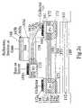
- FIG. 1 a and FIG. 1 bshow the layers of a structure in accordance with an embodiment of the invention and from which all the device structures associated with the optoelectronic technology can be made.
- the structure of FIG. 1Acan be made, for example, using known molecular beam epitaxy (MBE) techniques.
- a first semiconductor layer 151 of AlAs and a second semiconductor layer 152 of GaAsare deposited in pairs upon a semiinsulating gallium arsenide substrate 149 in sequence to form a dielectric distributed bragg reflector (DBR) mirror.
- DBRdielectric distributed bragg reflector
- the number of AlAs layerswill preferably always be one greater than the number of GaAs layers so that the first and last layers of the mirror are shown as layer 151 .
- the AlAs layerswill be subsequently subjected to high temperature steam oxidation to produce the compound Al x O y so that a mirror will be formed at the designed center wavelength. Therefore the thicknesses of layers 151 and 152 in the mirror are chosen so that the final optical thickness of GaAs and Al x O y are 1 ⁇ 4 wavelength of the center wavelength ⁇ D .
- the active device structurewhich consists of two HFET devices. The first of these is a p-channel HFET which has a p modulation doped quantum well and is positioned with the gate terminal on the lower side (i.e. on the mirror as just described) and the collector terminal on the upper side.
- the second of theseis an n-channel HFET which has an n modulation doped quantum well and is positioned with the gate terminal on the top side and the collector terminal on the lower side which is the collector of the p-channel device. Therefore a non-inverted N-channel device is stacked upon an inverted p-channel device to form the active device structure.
- the layer structurebegins with layer 153 of heavily N+ doped GaAs of about 2000 ⁇ thickness to enable the formation of ohmic contacts and this is the gate electrode of the p channel device.
- layer 153Deposited on layer 153 is layer 154 of N type Al x 1Ga 1-x1 As with a typical thickness of 500–3000 ⁇ and a typical doping of 5 ⁇ 10 17 cm ⁇ 3 .
- This layerserves as part of the PHFET gate and optically as the lower waveguide cladding layers for all laser, amplifier and modulator structures.
- the next layer layer layer 155is Al x2 1Ga 1-x2 As of thickness about 380–500 ⁇ and where x 2 is about 15%.
- the first 60–80 ⁇ (layer 155 a )is doped N+ type in the form of delta doping
- the next 200–300 ⁇ (layer 155 b )is undoped
- the next 80 ⁇ (layer 155 c )is doped P+ type in the form of delta doping
- the last 20–30 ⁇ (layer 155 d )is undoped to form a spacer layer.
- This layerforms the lower separate confinement heterostructure (SCH) layer for the laser, amplifier and modulator devices
- the next layersdefine the quantum well(s) of the PHFET.
- a strained quantum wellthis consists of a spacer layer 156 of about 10–25 ⁇ of undoped GaAs and then combinations of a well of 40–80 ⁇ (labeled 157 ) and a barrier of undoped GaAs (labeled 158 ).
- the wellmay be comprised of a range of compositions.
- the quantum wellis formed from a In 0.2 Ga 0.8 AsN composition with the nitrogen content varying from 0% to 5% depending upon the desired natural emission frequency.
- the nitrogen contentwill be 0%; for a natural emission frequency of 1.3 ⁇ m, the nitrogen content will be approximately 2%; and for a natural emission frequency of 1.5 ⁇ m, the nitrogen content will be approximately 4–5%.
- the well barrier combinationwill typically be repeated three times. Unstrained quantum wells are also possible. Following the last barrier of undoped GaAs is a layer 159 of undoped Al x2 1Ga 1-x2 which forms the collector of the PHFET device and is about 0.5 ⁇ m in thickness. All of the layers grown thus far form the PHFET device with the gate contact on the bottom.
- Layer 159also forms the collector region of the NHFET device.
- Deposited on 159is a layer 160 of undoped GaAs of about 200–250 ⁇ which forms the barrier of the first quantum well.
- This layeris wider than the normal barrier layer of about 100 ⁇ because it accommodates the growth interruption to change the growth temperature from 610° C. (as required for optical quality Al x2 1Ga 1-x2 As layers) to about 530° C. for the growth of InGaAs. Therefore layer 160 is divided into a single layer 160 a of about 150 ⁇ and a repeating barrier layer of about 100 ⁇ .
- the next layer 161is the quantum well of In 0.2 Ga 0.8 As which is undoped and about 40–80 ⁇ in thickness.
- the quantum well layer 161need not be of the same formulation as the quantum well layer 157 .
- the barrier of 100 ⁇ and quantum well of 40–80 ⁇may be repeated, e.g., three times.
- a barrier layer 162of about 10–30 ⁇ of undoped GaAs which accommodates a growth interruption and a change of growth temperature.
- a layer 163of about 300–500 ⁇ of Al x2 1Ga 1-x2 As.
- Layer 163is comprised from bottom to top of an undoped spacer layer 163 a of 20–30 ⁇ of Al x2 1Ga 1-x2 As, a layer 163 b of N+ type doping of about 3–5 ⁇ 10 18 cm ⁇ 3 which is a modulation doped layer, a capacitor spacing layer 163 c of about 200–300 ⁇ which is undoped and a P+ type delta doped layer 163 d of about 60–80 ⁇ and doping about 3–5 ⁇ 10 18 cm ⁇ 3 to form the top plate of the capacitor.
- the doping species for layer 163 dis preferably carbon (C) to ensure diffusive stability.
- layer 163 dIn contrast to layer 163 b which is always depleted, layer 163 d should never be totally depleted in operation.
- Layers 163 d and 163 bform the two plates of a parallel plate capacitor which forms the field-effect input to all devices.
- layer 163is the upper SCH region.
- Layer 163must be very thin to enable very high frequency operation. In the illustrated embodiment, for a transistor cutoff frequency of 40 GHz, a thickness of 300 ⁇ would be used, and for 90 GHz a thickness of 200 ⁇ would be more appropriate.
- Layer 164 of Al x1 Ga 1-x1 Asis deposited next to form part of the upper waveguide cladding layer for the laser, amplifier and modulator devices.
- Layer 164may have a first thin sublayer 164 a of, e.g., 10–20 ⁇ thickness and having a P+ typical doping of 10 19 cm ⁇ 3 .
- a second sublayer 164 bhas a P doping of 1–5 ⁇ 10 17 cm ⁇ 3 and a typical thickness of 700 ⁇ .
- Deposited nextis layer 165 of GaAs or a combination of GaAs and InGaAs which is about 50–100 ⁇ thick and doped to a very high level of P+ type doping (about 1 ⁇ 10 20 cm ⁇ 3 ) to enable the best possible ohmic contact.
- a dielectric mirroris deposited on this structure during the fabrication process.
- the distance between the mirrorsis the thickness of all layers from 153 to 165 inclusive. In designing this structure, this thickness must represent an integral number of 1 ⁇ 4 wavelengths at the designated wavelength and the thickness of layers 164 and/or 159 is adjusted to enable this condition.
- bipolar and field-effect transistors and optoelectronic devices in the form of thyristors and transistorscan be made in accordance with a generalized set of fabrication steps.
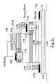
- the first structure shown in FIG. 2 ais the N channel HFET (NHFET).
- NFETN channel HFET
- the electrodeis also labeled as an emitter because the same set of contacts may be used to operate the structure as a bipolar device which is shown more optimally in FIGS. 2 b and 2 c ).
- Device fabricationbegins with the deposition of the refractory gate which is followed by an ion implant 170 of N type ions to form self-aligned contacts to the channel consisting of the layers 161 and 160 .
- an ion implant 170 of N type ionsis performed on the source side of the FET to form self-aligned contacts to the channel consisting of the layers 161 and 160 .
- the structureis etched down to near (about 1000 ⁇ above) the p type quantum wells 157 and an ion implant 173 of P type ions is performed to contact the p type inversion channel.
- an insulating implant 171such as oxygen is performed under the N type drain implant to reduce the capacitance for high speed operation.
- RTArapid thermal anneal
- the deviceis isolated from other devices by an etch down to the semiinsulating substrate which includes an etch through the mirror pairs 151 / 152 of AlAs/GaAs.
- the deviceis oxidized in a steam ambient to create layers of AlO/GaAs to perform as the final DBR mirror.
- the exposed sidewalls of the etched AlGaAs layersare passivated by the formation of very thin layers of oxide.
- the final step in the fabricationis the deposition of Au metal contacts. These contacts come in three forms.
- FIG. 2 bA second structure is shown in FIG. 2 b in which the same fabrication steps have been used, but the configuration has been more appropriately optimized as a bipolar device.
- both of the self-aligned implants 170 which contact the channelare connected as base or control electrodes and have the function of controlling the level of charge in the inversion channel.
- the channel chargecontrols the thermionic current flow between the emitter and collector producing a thermionic bipolar device.
- the deviceis then etched to the collector mesa which is established about 1000 ⁇ above the p type quantum wells 157 and these wells are contacted by a P+ type ion implant, 173 .
- the remainder of the processis the same as in FIG.
- this bipolaris a p ⁇ np device which would be grown with an inversion channel which is normally on.
- the p type bipolaris always inferior to the n type bipolar and therefore the main application for this device is as the p type component in a complementary bipolar technology.
- the devicecan be constructed differently as shown in FIG. 2 c , by creating the source contact 169 a by self-alignment of implant 170 to one side of the emitter contact 168 and the collector contact 172 b by self-alignment of implant 173 to the other side of the emitter contact.
- the fabrication sequencetherefore requires alignment of the mask within the emitter gate feature 168 , which limits how small the feature can be made. In the interests of higher speed, a tradeoff is therefore made. With this construction, the collector resistance has been optimized at the expense of the overall source resistance.
- FIGS. 2 d – 2 fthe cross-section is shown of the PHFET which is identical in cross-section to the n ⁇ pn bipolar device.
- FIG. 2 dshows that the top p+ layer 165 is etched away and a N+ implant 179 is used before the refractory metal 168 is deposited in order to create a N contact to the collector region 159 of either the PHFET or the n ⁇ pn. bipolar device.
- the refractory contact 168as a mask, the semiconductor is etched to within 1000 ⁇ of the p quantum wells and then the P+ type implant 173 is performed to create self-aligned contacts to the p inversion channel 157 / 158 .
- the P+ type implantcan be made deep enough to penetrate through to the SI substrate below which has the benefits of low capacitance for both bipolar and HFET high speed circuit operation.
- a RTA stepis performed to activate all implants.
- a mesais formed and the layers are etched down to the N+ layer 153 that forms the underlying gate electrode.
- a larger mesais etched down through the mirror layers to isolate all devices and the oxidation step is performed which creates mirrors under devices and passivates all device sidewalls.
- the final stepis the deposition of p type Au alloy metals 172 to the P+ type implants and the deposition of n type Au alloy metals 174 to the N+ gate layer.
- the collector contact resistanceis improved by making a self-aligned contact to the n type quantum well channel 161 / 160 by implantation using the refractory metal as a mask but implanting only on one side of the feature.
- the semiconductoris etched down to 1000 ⁇ from the p type quantum wells 157 / 158 and a P+ type implant 173 is performed which creates the base or source contact for the n ⁇ pn transistor by accessing the p type inversion channel (as in FIG. 2 d this implant may penetrate through to the SI substrate).
- This type of constructionrequires a larger gate/emitter feature 168 than the one in FIG. 2 d because an alignment is required in the center of the feature.
- a larger mesais formed to create the emitter contacts 174 a , 174 b to the N+ bottom layer 153 , device isolation is formed as in FIG. 2 d and also the Au contact metallurgy.
- the collector contact resistanceis reduced at the expense of the base (source) access resistance. Therefore, in an attempt to achieve higher speed, higher base access resistance is tolerated in order to achieve lower collector access resistance.
- FIG. 2 fthe device cross-section of another approach to obtain low collector access resistance is shown which is potentially superior to FIGS. 2 e and 2 d .
- the materialis initially etched to remove layers 165 , 164 and 163 d . By doing this etch, all of the P+ type layers are removed prior to the deposition of the refractory contact.
- a W/In contact metallurgy and the use of the RTA stepBy deposition of a W/In contact metallurgy and the use of the RTA step, a small amount of alloying occurs which is sufficient to cause the W/In to interact with the N+ charge sheet layer, 163 b .
- Using this approachrequires extremely tight control of the semiconductor etch to enable precise etching and removal of the P+ charge layer.
- the epitaxial growthhas been designed to concentrate all of the p type barrier charge into a thin sheet spaced away from the n type modulation doping. By separating the two charge sheets in this fashion, it is possible to etch to the position between them and thus effectively remove all of the p type doping layers from the top of the device. If this approach can be implemented effectively, it is the optimum approach because it may minimize the collector resistance and the base resistance together and, at the same time the collector capacitance.
- FIGS. 2 a – 2 fcan be formed adjacent each other (e.g., on separate mesas) and interconnected as desired.
- the NHFET structure of FIG. 2 a and PHFET structure of FIG. 2 dcan be interconnected to form complementary FET circuits where the gate terminal 168 of FIG. 2 a is coupled to the gate terminal 174 a or 174 b of FIG. 2 d , the drain 169 b of FIG. 2 a is coupled to the drain 172 b of FIG. 2 d , the NHFET source 169 a of FIG.
- mesasare formed by etching down to desired layers.
- a mesacan be formed, e.g., by etching down to the top mirror layer 152 , or even deeper down to the substrate layer 149 .
- FIGS. 2 g – 2 jthe fabrication sequences previously described are adapted to the formation of optically emitting, detecting, modulating and amplifying devices.
- FIG. 2 gshows the device cross-section of the thyristor device with N+ ion implants 170 used to form self-aligned channel contacts to the n type inversion channel and P+ ion implants 173 used to form self-aligned channel contacts to the p type inversion channel.
- These channel injectorsenable switching of the thyristor with n type and/or p type high impedance third terminal inputs. These implants are formed using the identical fabrication steps as just described in FIGS. 2 a – 2 f .
- the subcollector or backgate connectionis also created by etching to the N+ bottom layer 153 and applying the AuGe/Ni/Au ohmic alloy contact 174 ( 174 a , 174 b ) and the p type and n type implants 173 / 170 are contacted by p type and n type Au alloy metals ( 172 and 169 ) respectively as described previously.
- the key difference for the optical devicesis in the formation of the emitter contact.
- the device fabricationbegins with the definition of alignment marks (not shown) by etching and then the deposition of a layer of Si 3 N 4 (not shown) to act as protection for the surface layer and as a blocking layer for subsequent ion implants.
- an ion implant 175 of N type ionsis performed using a photomask that is aligned to the alignments marks, and produces an optical aperture 176 defined by the separation between the implants.
- the implantscreate a p-n junction in the layers between the n type quantum wells and the surface and the space between the implants defines the region in which the current may flow and therefore the optically active region.
- the currentcannot flow into the n implanted regions 175 because of the barrier to current injection.
- the current flow trajectoryis shown in the Figure.
- the laser threshold conditionis reached before the voltage for turn-on of this barrier.
- the refractory gate 168is deposited and defined as an annulus which is also aligned to the alignment marks and therefore to the implant.
- a dielectric mirroris deposited on this structure during the fabrication process.
- the distance between the mirrorsis the thickness of all layers from 153 to 165 inclusive.
- this thicknesspreferably represents an integral number of 1 ⁇ 4 wavelengths at the designated wavelength and the thickness of layer 164 and/or 159 is adjusted to enable this condition.
- a dielectric mirroris created on the top of the device by the deposition of dielectric layers 166 and 167 , typically layers of SiO 2 and a high refractive index material such as GaAs or GaN.
- the dielectric mirrorserves two purposes. It defines a cavity for the vertical emission and absorption of light and it serves as the cladding layer for a waveguide so that light may propagate in the plane of the wafer. For most applications, only the electron third terminal 169 ( 169 a , 169 b ) and not the hole third terminal 172 ( 172 a , 172 b ) will be used. A cross-section of a device without the hole terminals 172 is shown in FIG. 2 h with the device operating as a vertical cavity emitter or detector.
- this deviceis multifunctional. If the source 169 is biased positively or the collector 172 is biased negatively, then the thyristor will switch to its on state and if the biasing is above the threshold for lasing, then laser emission will be obtained through the optical aperture at the top surface of the device. This is the operation of a vertical cavity laser. If the thyristor is in the off state and light is admitted through the top optical aperture, then the device functions as a digital detector in the sense that when sufficient electron-hole pairs have been generated to achieve the critical switching condition, then switching to the on state will occur.
- the configuration for an optical receiveris shown in FIG. 3 .
- the deviceis biased to its supply voltage V DD through a load resistor R L , 180 .
- the N+ electron source terminal 169(designated the injector) is biased to the most positive voltage V DD through a current source, 181 .
- the thyristorWhen light is incident on the detector of sufficient intensity to produce photocurrent in excess of the current source drawing on the injector terminal, the thyristor will switch on. When the incident light is reduced, the thyristor will switch off because the current source on the injector drains the channel of charge. Therefore this circuit functions as an optical receiver.
- the device shown in FIG. 2 hmay also function as an in-plane or waveguide device if a grating is formed in the upper mirror layer 166 , 167 according to the techniques discussed in U.S. Pat. No. 6,031,243 to Taylor, which is hereby incorporated by reference herein in its entirety.
- the gratingperforms the function of diffracting the light produced by the vertical cavity into light propagating in a waveguide which has the upper ( 166 , 167 ) and lower ( 151 , 152 ) mirror layers as waveguide cladding layers and the implants 170 as lateral confinement regions.
- FIG. 2 iA plan view of this device showing how the passive waveguides connect to the active waveguides is shown in FIG.
- This devicehas the modes of operation of a laser, a detector, a modulator and an amplifier.
- a laserall light generated within the vertical cavity is directed laterally into the waveguide formed by the mirrors and is then connected to a passive waveguide at the edge of the device.
- a waveguide detectorthe light is entered into the device from a passive waveguide, is diffracted into the vertical cavity mode and is absorbed resonantly in the vertical cavity.
- the devicewould be biased electrically as shown in FIG. 3 and the function of the circuit would be that of an optical receiver.
- the subcollector contact 174 in FIG. 2 h or 2 iis not connected (i.e.
- the devicemay operate as a simple pin detector with connections to the gate 168 and to the source 169 , since a photocurrent would be produced in the gate/emitter to source circuit and switching would be prohibited.
- a waveguide absorption modulatortwo forms of operation are possible.
- the devicemay perform as a digital modulator if the device is biased as a thyristor and the electrical data is entered via the injector. The injector injects current into the device and it switches to the on state if the data is a one. In the switched on state there is no optical loss and an optical “1” is produced.
- the injectorcontinuously removes charge (current flows out of the device) and forces the device to remain in the off state. In the off state, all of the optical signal is absorbed and an optical “0” is produced.
- the devicemay operate either with or without the grating. However, with the use of the grating a shorter length of device is possible.
- the devicemay perform as an analog modulator if the subcollector of the device is not connected. As an analog modulator, any level of modulated intensity is obtainable by varying the injector input voltage up to the maximum absorption change of the modulator produced by the maximum voltage for FET conduction without bipolar conduction, since switching may not occur with the subcollector disconnected.
- the final mode of operation of the deviceis as a waveguide amplifier. If the device in FIG. 2 i is operated in the switched on state but well below the threshold for lasing, then optical signals input to the device from a passive waveguide at one end may be amplified to a larger optical signal at the output of the device.
- the gratingmay or may not be used. However, the use of the grating will result in a shorter device. It will also result in the stabilization of the polarization, since the grating supports the TE mode much more strongly than the TM mode.
- the fabricationis identical to that of the single modulator device except that prior to the rapid thermal anneal (RTA), the nitride layer that protects the optical opening is patterned to create an opening 178 that evenly divides the total optically active area into two waveguide channels. The p+ layers are removed in this opening. Then SiO 2 is deposited and during the RTA, vacancy disordering occurs, so that a slightly larger energy gap is created in the region 178 . This energy gap provides an ideal region for evanescent coupling to occur. The remainder of the processing follows that of the waveguide devices discussed earlier. This device has two passive waveguide channels as inputs and two passive waveguide channels as output as indicated by the plan view of the device in FIG. 3 c .
- RTArapid thermal anneal
- Such a deviceis called a directional coupler and the switching of light from mode A to mode B in FIG. 2 j is induced by a differential change in the waveguide propagation constant between guides A and B.
- This changeis produced by the injection of charge into the inversion channel from the self-aligned channel contact and can be produced by the injection of charge into one or the other of the two channels (but not both).
- the construction technique of the two channelsmust be such that the two waveguides are identical in all respects so that the coupling length will be constant over a large area.
- the subcollectoris biased to ground through a load resistor and the emitters are biased positively. Therefore both waveguide sections are potential switches.
- the cross statecorresponds to the optical signal on channel A coupling to channel B only once and vice versa for the optical signal on channel B.
- the channel A thyristoris switched on. Then the transition from the through state to the cross state occurs when the source input to channel B is injected with charge. When channel B is emptied of charge, the absorption increase is removed in that channel and therefore also the increase in index is removed.
- the wavelength of the optical modemay need to be adjusted to coincide with the maximum change in the refractive index. This may be accomplished by localized heating of the switch using a dedicated HFET as a heating element.
- the passive waveguides interconnecting all devicesare also created by the use of the vacancy disordering technique.
- a ridgeis etched and is coated with SiO 2 so that a non-absorbing (and therefore low loss) region is formed.
- the passive waveguideis later coated with the upper dielectric mirror layers to provide the upper cladding layers for waveguide propagation.
Landscapes
- Physics & Mathematics (AREA)
- Optics & Photonics (AREA)
- Chemical & Material Sciences (AREA)
- Nonlinear Science (AREA)
- General Physics & Mathematics (AREA)
- Engineering & Computer Science (AREA)
- Nanotechnology (AREA)
- Life Sciences & Earth Sciences (AREA)
- Biophysics (AREA)
- Crystallography & Structural Chemistry (AREA)
- Bipolar Transistors (AREA)
- Thyristors (AREA)
- Junction Field-Effect Transistors (AREA)
- Semiconductor Lasers (AREA)
Abstract
Description
Claims (37)
Priority Applications (1)
| Application Number | Priority Date | Filing Date | Title |
|---|---|---|---|
| US10/469,649US7012274B2 (en) | 2001-03-02 | 2002-03-04 | Modulation doped thyristor and complementary transistors combination for a monolithic optoelectronic integrated circuit |
Applications Claiming Priority (3)
| Application Number | Priority Date | Filing Date | Title |
|---|---|---|---|
| US09/798,316US6479844B2 (en) | 2001-03-02 | 2001-03-02 | Modulation doped thyristor and complementary transistor combination for a monolithic optoelectronic integrated circuit |
| PCT/US2002/006802WO2002071490A1 (en) | 2001-03-02 | 2002-03-04 | A modulation doped thyristor and complementary transistor combination for a monolithic optoelectronic integrated circuit |
| US10/469,649US7012274B2 (en) | 2001-03-02 | 2002-03-04 | Modulation doped thyristor and complementary transistors combination for a monolithic optoelectronic integrated circuit |
Publications (2)
| Publication Number | Publication Date |
|---|---|
| US20040075090A1 US20040075090A1 (en) | 2004-04-22 |
| US7012274B2true US7012274B2 (en) | 2006-03-14 |
Family
ID=25173092
Family Applications (2)
| Application Number | Title | Priority Date | Filing Date |
|---|---|---|---|
| US09/798,316Expired - LifetimeUS6479844B2 (en) | 2001-03-02 | 2001-03-02 | Modulation doped thyristor and complementary transistor combination for a monolithic optoelectronic integrated circuit |
| US10/469,649Expired - LifetimeUS7012274B2 (en) | 2001-03-02 | 2002-03-04 | Modulation doped thyristor and complementary transistors combination for a monolithic optoelectronic integrated circuit |
Family Applications Before (1)
| Application Number | Title | Priority Date | Filing Date |
|---|---|---|---|
| US09/798,316Expired - LifetimeUS6479844B2 (en) | 2001-03-02 | 2001-03-02 | Modulation doped thyristor and complementary transistor combination for a monolithic optoelectronic integrated circuit |
Country Status (6)
| Country | Link |
|---|---|
| US (2) | US6479844B2 (en) |
| EP (1) | EP1371098A4 (en) |
| JP (1) | JP2004534380A (en) |
| KR (1) | KR100912358B1 (en) |
| CN (1) | CN100530680C (en) |
| WO (1) | WO2002071490A1 (en) |
Cited By (15)
| Publication number | Priority date | Publication date | Assignee | Title |
|---|---|---|---|---|
| US20050207692A1 (en)* | 2004-03-22 | 2005-09-22 | Morio Wada | Optical switch |
| US20060124829A1 (en)* | 2004-12-10 | 2006-06-15 | Song Hyun W | Surface emitting laser device including optical sensor and optical waveguide device employing the same |
| US20060284247A1 (en)* | 2005-06-17 | 2006-12-21 | Godfrey Augustine | Novel method for integrating silicon CMOS and AlGaN/GaN wideband amplifiers on engineered substrates |
| US20080173567A1 (en)* | 2007-01-22 | 2008-07-24 | Charles Magee | Vehicle cup and plate holders |
| US20090003399A1 (en)* | 2007-06-26 | 2009-01-01 | Taylor Geoff W | Integrated Circuit Employing Low Loss Spot-Size Converter |
| US20100123121A1 (en)* | 2008-03-18 | 2010-05-20 | Taylor Geoff W | Thyristor Radiation Detector Array and Applications Thereof |
| US20100193771A1 (en)* | 2008-12-31 | 2010-08-05 | Prashant Majhi | Quantum well mosfet channels having uni-axial strain caused by metal source/drains, and conformal regrowth source/drains |
| US20110064370A1 (en)* | 2009-09-14 | 2011-03-17 | The Aerospace Corporation | Systems and methods for preparing films using sequential ion implantation, and films formed using same |
| US20110109955A1 (en)* | 2009-11-06 | 2011-05-12 | Electronics And Telecommunications Research Institute | Electro-optic device |
| US20140070351A1 (en)* | 2012-09-07 | 2014-03-13 | Sumitomo Electric Industries, Ltd. | Method for manufacturing optical waveguide receiver and optical waveguide receiver |
| US8946864B2 (en) | 2011-03-16 | 2015-02-03 | The Aerospace Corporation | Systems and methods for preparing films comprising metal using sequential ion implantation, and films formed using same |
| US20160099335A1 (en)* | 2013-04-16 | 2016-04-07 | Fujitsu Limited | Semiconductor device and method of manufacturing the same |
| US9324579B2 (en) | 2013-03-14 | 2016-04-26 | The Aerospace Corporation | Metal structures and methods of using same for transporting or gettering materials disposed within semiconductor substrates |
| US10116115B2 (en) | 2017-02-22 | 2018-10-30 | Geoff W. Taylor | Integrated circuit implementing a VCSEL array or VCSEL device |
| TWI793753B (en)* | 2020-11-18 | 2023-02-21 | 日商村田製作所股份有限公司 | Semiconductor device |
Families Citing this family (115)
| Publication number | Priority date | Publication date | Assignee | Title |
|---|---|---|---|---|
| US6849866B2 (en)* | 1996-10-16 | 2005-02-01 | The University Of Connecticut | High performance optoelectronic and electronic inversion channel quantum well devices suitable for monolithic integration |
| US7181144B1 (en) | 1998-07-09 | 2007-02-20 | Zilog, Inc. | Circuit design and optics system for infrared signal transceivers |
| JP2001281473A (en)* | 2000-03-28 | 2001-10-10 | Toshiba Corp | Photonic crystal and its manufacturing method, optical module and optical system |
| US7247892B2 (en)* | 2000-04-24 | 2007-07-24 | Taylor Geoff W | Imaging array utilizing thyristor-based pixel elements |
| US6479844B2 (en)* | 2001-03-02 | 2002-11-12 | University Of Connecticut | Modulation doped thyristor and complementary transistor combination for a monolithic optoelectronic integrated circuit |
| CA2478071C (en)* | 2001-03-27 | 2010-09-21 | Metrophotonics Inc. | Single-mode vertical integration of active devices within passive semiconductor waveguides, a method and its applications for use in planar wdm components |
| JP4468609B2 (en)* | 2001-05-21 | 2010-05-26 | 株式会社ルネサステクノロジ | Semiconductor device |
| US7831151B2 (en) | 2001-06-29 | 2010-11-09 | John Trezza | Redundant optical device array |
| US6704472B2 (en)* | 2001-11-05 | 2004-03-09 | Triquint Technology Holding Co. | Optoelectronic device having an integrated capacitor formed thereon and method of manufacturing the same |
| US6847054B1 (en)* | 2002-02-07 | 2005-01-25 | Finisar Corporation | Optical transistor and method thereof |
| US6954473B2 (en) | 2002-10-25 | 2005-10-11 | Opel, Inc. | Optoelectronic device employing at least one semiconductor heterojunction thyristor for producing variable electrical/optical delay |
| US6841795B2 (en)* | 2002-10-25 | 2005-01-11 | The University Of Connecticut | Semiconductor devices employing at least one modulation doped quantum well structure and one or more etch stop layers for accurate contact formation |
| US6995407B2 (en) | 2002-10-25 | 2006-02-07 | The University Of Connecticut | Photonic digital-to-analog converter employing a plurality of heterojunction thyristor devices |
| US7332752B2 (en) | 2002-10-25 | 2008-02-19 | The University Of Connecticut | Optoelectronic circuit employing a heterojunction thyristor device to convert a digital optical signal to a digital electrical signal |
| US7015120B2 (en)* | 2002-10-25 | 2006-03-21 | The University Of Connecticut | Method of fabricating semiconductor devices employing at least one modulation doped quantum well structure and one or more etch stop layers for accurate contact formation |
| US7776753B2 (en)* | 2002-10-25 | 2010-08-17 | University Of Connecticut | Method of fabricating semiconductor devices employing at least one modulation doped quantum well structure and one or more etch stop layers for accurate contact formation |
| US7556976B2 (en)* | 2002-10-25 | 2009-07-07 | The University Of Connecticut | Method of fabricating semiconductor devices employing at least one modulation doped quantum well structure and one or more etch stop layers for accurate contact formation |
| FR2848727B1 (en)* | 2002-12-13 | 2005-02-18 | Thales Sa | HIGH SPEED SPIN VALVE TRANSISTOR |
| US6974969B2 (en) | 2003-01-13 | 2005-12-13 | The University Of Connecticut | P-type quantum-well-base bipolar transistor device employing interdigitated base and emitter formed with a capping layer |
| US7064697B2 (en) | 2003-01-29 | 2006-06-20 | The University Of Connecticut | Photonic sigma delta analog-to-digital conversation employing dual heterojunction thyristors |
| US6800880B1 (en)* | 2003-08-08 | 2004-10-05 | National Kaohsiung Normal University | Heterojunction bipolar transistors with extremely low offset voltage and high current gain |
| US7064359B2 (en)* | 2003-08-20 | 2006-06-20 | Matsushita Electric Industrial Co., Ltd. | Switching semiconductor device and switching circuit |
| US7354780B2 (en) | 2003-08-22 | 2008-04-08 | The Board Of Trustees Of The University Of Illinois | Semiconductor light emitting devices and methods |
| US7696536B1 (en)* | 2003-08-22 | 2010-04-13 | The Board Of Trustees Of The University Of Illinois | Semiconductor method and device |
| US7091082B2 (en)* | 2003-08-22 | 2006-08-15 | The Board Of Trustees Of The University Of Illinois | Semiconductor method and device |
| US7286583B2 (en)* | 2003-08-22 | 2007-10-23 | The Board Of Trustees Of The University Of Illinois | Semiconductor laser devices and methods |
| US7998807B2 (en)* | 2003-08-22 | 2011-08-16 | The Board Of Trustees Of The University Of Illinois | Method for increasing the speed of a light emitting biopolar transistor device |
| US7289547B2 (en)* | 2003-10-29 | 2007-10-30 | Cubic Wafer, Inc. | Laser and detector device |
| US7253015B2 (en)* | 2004-02-17 | 2007-08-07 | Velox Semiconductor Corporation | Low doped layer for nitride-based semiconductor device |
| US7333731B2 (en) | 2004-04-26 | 2008-02-19 | The University Of Connecticut | Multifunctional optoelectronic thyristor and integrated circuit and optical transceiver employing same |
| WO2006006312A1 (en)* | 2004-07-07 | 2006-01-19 | Nec Corporation | Optical semiconductor device and optical communication device |
| CN100412518C (en)* | 2004-07-30 | 2008-08-20 | 中国科学院物理研究所 | Laser detector made of oxide multilayer film material |
| DE102004044835B4 (en)* | 2004-09-14 | 2008-12-11 | Atmel Germany Gmbh | Integrated semiconductor cascode circuit for high-frequency applications |
| EP1842268B1 (en)* | 2005-01-26 | 2019-08-28 | Philipps-Universität Marburg | Iii/v semiconductor |
| JP4474292B2 (en)* | 2005-01-28 | 2010-06-02 | トヨタ自動車株式会社 | Semiconductor device |
| US7385230B1 (en)* | 2005-02-08 | 2008-06-10 | The University Of Connecticut | Modulation doped thyristor and complementary transistor combination for a monolithic optoelectronic integrated circuit |
| US7439556B2 (en)* | 2005-03-29 | 2008-10-21 | Coldwatt, Inc. | Substrate driven field-effect transistor |
| US7439557B2 (en)* | 2005-03-29 | 2008-10-21 | Coldwatt, Inc. | Semiconductor device having a lateral channel and contacts on opposing surfaces thereof |
| US7675090B2 (en)* | 2005-05-13 | 2010-03-09 | Flextronics International Usa, Inc. | Semiconductor device having a contact on a buffer layer thereof and method of forming the same |
| US7339208B2 (en) | 2005-05-13 | 2008-03-04 | Coldwatt, Inc. | Semiconductor device having multiple lateral channels and method of forming the same |
| US7564074B2 (en)* | 2005-08-25 | 2009-07-21 | Flextronics International Usa, Inc. | Semiconductor device including a lateral field-effect transistor and Schottky diode |
| US7285807B2 (en)* | 2005-08-25 | 2007-10-23 | Coldwatt, Inc. | Semiconductor device having substrate-driven field-effect transistor and Schottky diode and method of forming the same |
| US7462891B2 (en)* | 2005-09-27 | 2008-12-09 | Coldwatt, Inc. | Semiconductor device having an interconnect with sloped walls and method of forming the same |
| US7535034B2 (en)* | 2006-02-27 | 2009-05-19 | The Board Of Trustees Of The University Of Illinois | PNP light emitting transistor and method |
| US7663183B2 (en)* | 2006-06-21 | 2010-02-16 | Flextronics International Usa, Inc. | Vertical field-effect transistor and method of forming the same |
| US8415737B2 (en) | 2006-06-21 | 2013-04-09 | Flextronics International Usa, Inc. | Semiconductor device with a pillar region and method of forming the same |
| US7541640B2 (en)* | 2006-06-21 | 2009-06-02 | Flextronics International Usa, Inc. | Vertical field-effect transistor and method of forming the same |
| US7945158B2 (en)* | 2006-08-18 | 2011-05-17 | Tellabs Operations, Inc. | Transponder-less verification of the configuration of an optical network node |
| US9197132B2 (en) | 2006-12-01 | 2015-11-24 | Flextronics International Usa, Inc. | Power converter with an adaptive controller and method of operating the same |
| US7711015B2 (en)* | 2007-04-02 | 2010-05-04 | The Board Of Trustees Of The University Of Illinois | Method for controlling operation of light emitting transistors and laser transistors |
| US7657131B2 (en)* | 2007-06-28 | 2010-02-02 | Intel Corporation | Systems and methods for integrated optical circuitry for high data rate optical transmission and reception |
| US7764850B2 (en)* | 2008-01-25 | 2010-07-27 | Hewlett-Packard Development Company, L.P. | Optical modulator including electrically controlled ring resonator |
| JP2009286048A (en)* | 2008-05-30 | 2009-12-10 | Fuji Xerox Co Ltd | Light source head and image forming apparatus |
| JP5386764B2 (en)* | 2008-10-10 | 2014-01-15 | 独立行政法人産業技術総合研究所 | Photodetector |
| WO2010083514A1 (en) | 2009-01-19 | 2010-07-22 | Flextronics International Usa, Inc. | Controller for a power converter |
| US20100276699A1 (en)* | 2009-05-04 | 2010-11-04 | University Of South Carolina | Silicon Carbide and Related Wide Bandgap Semiconductor Based Optically-Controlled Power Switching Devices |
| CN101666919B (en)* | 2009-09-21 | 2012-06-27 | 浙江大学 | Silicon slit waveguide electrode with etching tolerance |
| RU2472248C2 (en)* | 2010-03-03 | 2013-01-10 | Общество с ограниченной ответственностью "Интелсоб" (ООО "Интелсоб") | High-voltage high-temperature quick-acting thyristor with field control |
| CN101814527A (en)* | 2010-04-22 | 2010-08-25 | 复旦大学 | Power device and method for performing conductivity modulation by using photoelectron injection |
| CN101937873B (en)* | 2010-08-31 | 2012-07-11 | 中国科学院半导体研究所 | Manufacturing method of bipolar transistor and semiconductor laser monolithic integrated device |
| JP5845568B2 (en) | 2010-11-02 | 2016-01-20 | 富士通株式会社 | Semiconductor device and manufacturing method thereof |
| CN103430084A (en)* | 2011-03-17 | 2013-12-04 | 日本碍子株式会社 | Optical modulation element |
| CN102299170B (en)* | 2011-08-08 | 2013-07-24 | 中国电子科技集团公司第五十五研究所 | GaAs pseudomorphic high-electron-mobility transistor epitaxy material |
| JP2014529758A (en) | 2011-08-18 | 2014-11-13 | オペル ソーラー,インコーポレイティド | Optical closed-loop microresonator and thyristor memory device |
| EP2752096A4 (en) | 2011-09-02 | 2015-07-29 | Quantum Electro Opto Sys Sdn | Opto-electronic circuits and techniques |
| US8970126B2 (en) | 2011-10-07 | 2015-03-03 | The Board Of Trustees Of The University Of Illinois | Opto-electronic devices and methods |
| US8842706B2 (en) | 2011-10-07 | 2014-09-23 | The Board Of Trustees Of The University Of Illinois | Opto-electronic oscillator and method |
| US9159873B2 (en) | 2011-11-14 | 2015-10-13 | Quantum Electro Opto Systems Sdn. Bhd. | High speed optical tilted charge devices and methods |
| CN103489860B (en)* | 2012-06-13 | 2016-02-10 | 稳懋半导体股份有限公司 | A compound semiconductor wafer structure |
| TWI505409B (en)* | 2012-06-13 | 2015-10-21 | Win Semiconductors Corp | Compound semiconductor wafer structure |
| US9082637B2 (en) | 2012-08-17 | 2015-07-14 | The University Of Connecticut | Optoelectronic integrated circuit |
| US8947925B2 (en) | 2012-08-17 | 2015-02-03 | The University Of Connecticut | Thyristor memory cell integrated circuit |
| JP2016500451A (en) | 2012-12-13 | 2016-01-12 | ユニバーシティ オブ コネティカット | Optical fiber coupler array |
| US9306672B2 (en)* | 2013-03-14 | 2016-04-05 | Encore Corporation | Method of fabricating and operating an optical modulator |
| US9111956B2 (en)* | 2013-03-14 | 2015-08-18 | Taiwan Semiconductor Manufacturing Company, Ltd. | Rectifier structures with low leakage |
| US9614112B2 (en) | 2013-09-11 | 2017-04-04 | The University Of Connecticut | Imaging cell array integrated circuit |
| US9166035B2 (en)* | 2013-09-12 | 2015-10-20 | Taiwan Semiconductor Manufacturing Company Limited | Delta doping layer in MOSFET source/drain region |
| JP6213103B2 (en)* | 2013-09-27 | 2017-10-18 | 三菱電機株式会社 | Semiconductor optical device and optical module |
| CN103745989B (en)* | 2013-12-31 | 2016-07-06 | 上海新傲科技股份有限公司 | Hemt |
| US9625647B2 (en) | 2014-01-29 | 2017-04-18 | The University Of Connecticut | Optoelectronic integrated circuit |
| US9508707B2 (en)* | 2014-02-27 | 2016-11-29 | Texas Instruments Incorporated | Quantum well-modulated bipolar junction transistor |
| US9523815B2 (en) | 2014-03-31 | 2016-12-20 | Stmicroelectronics Sa | ESD protection thyristor adapted to electro-optical devices |
| US9276160B2 (en) | 2014-05-27 | 2016-03-01 | Opel Solar, Inc. | Power semiconductor device formed from a vertical thyristor epitaxial layer structure |
| US10553633B2 (en)* | 2014-05-30 | 2020-02-04 | Klaus Y.J. Hsu | Phototransistor with body-strapped base |
| US9698457B2 (en) | 2014-07-28 | 2017-07-04 | The University Of Connecticut | Optoelectronic integrated circuitry for transmitting and/or receiving wavelength-division multiplexed optical signals |
| CN104319626A (en)* | 2014-10-11 | 2015-01-28 | 北京工业大学 | Microwave carrier directly modulated vertical-cavity surface-emitting laser |
| US9590742B2 (en) | 2014-12-22 | 2017-03-07 | Opel Solar, Inc. | Thyristor-based optical XOR circuit |
| US9590600B2 (en) | 2014-12-22 | 2017-03-07 | Opel Solar, Inc. | Thyristor-based optical flip-flop |
| US9209815B1 (en) | 2014-12-22 | 2015-12-08 | Opel Solar, Inc. | Thyristor-based optical charge pump for an optical phase lock loop |
| US9541945B2 (en) | 2014-12-22 | 2017-01-10 | Opel Solar, Inc. | Thyristor based optical and gate and thyristor-based electrical and gate |
| US9553715B2 (en) | 2014-12-22 | 2017-01-24 | Opel Solar, Inc. | Optical phase detector for an optical phase lock loop |
| US9544062B2 (en) | 2014-12-22 | 2017-01-10 | Opel Solar, Inc. | Coherent optical receiver |
| US9559636B2 (en) | 2014-12-22 | 2017-01-31 | Opel Solar, Inc. | Thyristor-based optoelectronic oscillator with tunable frequency and optical phase lock loop employing same |
| CN104795409B (en)* | 2015-03-11 | 2018-10-12 | 北京工业大学 | GaAs base PHEMTs and long wavelength's resonant cavity single-chip integration optical detector |
| US9201287B1 (en) | 2015-04-28 | 2015-12-01 | Opel Solar, Inc. | Photonic analog-to-digital converter |
| US9755060B2 (en) | 2015-06-11 | 2017-09-05 | Opel Solar, Inc. | Fabrication methodology for optoelectronic integrated circuits |
| US9679987B2 (en) | 2015-06-11 | 2017-06-13 | The University Of Connecticut | Fabrication methodology for optoelectronic integrated circuits |
| US9490336B1 (en) | 2015-06-11 | 2016-11-08 | Opel Solar, Inc. | Fabrication methodology for optoelectronic integrated circuits |
| US9590136B2 (en) | 2015-06-11 | 2017-03-07 | Opel Solar, Inc. | Semiconductor device for optoelectronic integrated circuits |
| US9450124B1 (en) | 2015-06-11 | 2016-09-20 | Opel Solar, Inc. | Fabrication methodology for optoelectronic integrated circuits |
| DE102016108700A1 (en) | 2016-05-11 | 2017-11-16 | Osram Opto Semiconductors Gmbh | Laser arrangement and operating method |
| JP6737008B2 (en)* | 2016-06-30 | 2020-08-05 | 富士ゼロックス株式会社 | Optical switch |
| CN106887789B (en)* | 2017-03-13 | 2019-10-18 | 中国科学院苏州纳米技术与纳米仿生研究所 | Semiconductor laser and method of making the same |
| US11309412B1 (en)* | 2017-05-17 | 2022-04-19 | Northrop Grumman Systems Corporation | Shifting the pinch-off voltage of an InP high electron mobility transistor with a metal ring |
| WO2018226963A1 (en) | 2017-06-08 | 2018-12-13 | Taylor Geoff W | Thyristor-based lidar detector array |
| US11125689B2 (en)* | 2018-07-13 | 2021-09-21 | The Government Of The United States Of America, As Represented By The Secretary Of The Navy | Highly stable semiconductor lasers and sensors for III-V and silicon photonic integrated circuits |
| RU2723910C1 (en)* | 2019-08-06 | 2020-06-18 | федеральное государственное автономное образовательное учреждение высшего образования "Южный федеральный университет" (Южный федеральный университет) | Photodetector with controlled redeployment of charge carrier density maxima |
| US12310129B2 (en)* | 2020-05-21 | 2025-05-20 | Faquir Chand Jain | Quantum dot channel (QDC) quantum dot gate transistors, memories and other devices |
| US11799268B2 (en) | 2020-08-24 | 2023-10-24 | Geoff W. Taylor | Semiconductor integrated circuit and methodology for making same |
| US11973075B2 (en) | 2021-02-22 | 2024-04-30 | Taiwan Semiconductor Manufacturing Company, Ltd. | Dual substrate side ESD diode for high speed circuit |
| CN113540283B (en)* | 2021-06-18 | 2023-01-24 | 西安理工大学 | Two-dimensional electron gas type photoconductive longitudinal switch and manufacturing method thereof |
| CN117916966A (en)* | 2021-09-17 | 2024-04-19 | 索尼集团公司 | Surface emitting laser element and light source device |
| CN114614340B (en)* | 2022-05-12 | 2022-07-29 | 山东大学 | Coplanar electrode vertical cavity surface emitting laser and preparation method thereof |
| DE102023116888A1 (en) | 2022-06-29 | 2024-01-04 | Ifm Electronic Gmbh | Optoelectronic component designed as a VCSEL with a heat spreading layer and method for producing one |
| CN119994634A (en)* | 2023-11-10 | 2025-05-13 | 中国科学院长春光学精密机械与物理研究所 | Single longitudinal mode transistor laser and system based on periodic current injection structure |
Citations (44)
| Publication number | Priority date | Publication date | Assignee | Title |
|---|---|---|---|---|
| US3919656A (en) | 1973-04-23 | 1975-11-11 | Nathan O Sokal | High-efficiency tuned switching power amplifier |
| US4424525A (en) | 1979-12-28 | 1984-01-03 | Fujitsu Limited | High electron mobility single heterojunction semiconductor devices |
| US4658403A (en) | 1983-11-08 | 1987-04-14 | Sharp Kabushiki Kaisha | Optical element in semiconductor laser device having a diffraction grating and improved resonance characteristics |
| US4683484A (en) | 1985-08-23 | 1987-07-28 | Bell Communications Research, Inc. | Lateral confinement of charge carriers in a multiple quantum well structure |
| US4806997A (en) | 1985-06-14 | 1989-02-21 | AT&T Laboratories American Telephone and Telegraph Company | Double heterostructure optoelectronic switch |
| US4814774A (en) | 1986-09-05 | 1989-03-21 | Herczfeld Peter R | Optically controlled phased array system and method |
| US4827320A (en) | 1986-09-19 | 1989-05-02 | University Of Illinois | Semiconductor device with strained InGaAs layer |
| US4829272A (en) | 1987-06-10 | 1989-05-09 | Elmec Corporation | Electromagnetic variable delay line system |
| US4899200A (en)* | 1988-06-03 | 1990-02-06 | Regents Of The University Of Minnesota | Novel high-speed integrated heterostructure transistors, photodetectors, and optoelectronic circuits |
| US4949350A (en) | 1989-07-17 | 1990-08-14 | Bell Communications Research, Inc. | Surface emitting semiconductor laser |
| US5010374A (en) | 1990-06-05 | 1991-04-23 | At&T Bell Laboratories | Quantum well laser utilizing an inversion layer |
| US5099299A (en)* | 1990-06-15 | 1992-03-24 | International Business Machines Corporation | Modulation doped base heterojunction bipolar transistor |
| US5105248A (en) | 1987-05-14 | 1992-04-14 | Massachusetts Institute Of Technology | Spatial light modulator using charge coupled device with quantum wells |
| US5111255A (en)* | 1990-06-05 | 1992-05-05 | At&T Bell Laboratories | Buried channel heterojunction field effect transistor |
| US5202896A (en) | 1991-07-16 | 1993-04-13 | The United States Of America As Represented By The Secretary Of The Air Force | Bipolar inversion channel field effect transistor laser |
| US5204871A (en) | 1990-03-29 | 1993-04-20 | Larkins Eric C | Bistable optical laser based on a heterostructure pnpn thyristor |
| US5224115A (en)* | 1991-07-17 | 1993-06-29 | The United States Of America As Represented By The Secretary Of The Air Force | Distributed feedback laser implemented using an active lateral grating |
| US5278427A (en)* | 1993-02-04 | 1994-01-11 | The United States Of America As Represented By The Secretary Of The Army | Quantum collector hot-electron transistor |
| US5337328A (en) | 1992-05-08 | 1994-08-09 | Sdl, Inc. | Semiconductor laser with broad-area intra-cavity angled grating |
| US5386128A (en) | 1994-01-21 | 1995-01-31 | The United States Of America As Represented By The Administrator Of The National Aeronautics And Space Administration | Monolithic in-based III-V compound semiconductor focal plane array cell with single stage CCD output |
| US5422501A (en) | 1991-03-28 | 1995-06-06 | Texas Instruments Incorporated | Method of integrating heterojunction bipolar transistors with heterojunction FETs and PIN diodes |
| US5436759A (en) | 1994-06-14 | 1995-07-25 | The Regents Of The University Of California | Cross-talk free, low-noise optical amplifier |
| US5567961A (en)* | 1992-08-21 | 1996-10-22 | Hitachi, Ltd. | Semiconductor device |
| US5652439A (en) | 1993-12-03 | 1997-07-29 | Imec | Fast electrical complete turn-off optical device |
| US5677552A (en)* | 1992-04-23 | 1997-10-14 | Nec Corporation | Optical control circuit for an optical pnpn thyristor |
| US5698900A (en) | 1996-07-22 | 1997-12-16 | The United States Of America As Represented By The Secretary Of The Air Force | Field effect transistor device with single layer integrated metal and retained semiconductor masking |
| US5828087A (en)* | 1995-12-22 | 1998-10-27 | Sharp Kabushiki Kaisha | AlInAs semiconductor device contaning Si and P |
| US5847414A (en)* | 1995-10-30 | 1998-12-08 | Abb Research Limited | Semiconductor device having a hetero-junction between SiC and a Group 3B-nitride |
| US6031243A (en)* | 1996-10-16 | 2000-02-29 | Geoff W. Taylor | Grating coupled vertical cavity optoelectronic devices |
| US6043519A (en) | 1996-09-12 | 2000-03-28 | Hughes Electronics Corporation | Junction high electron mobility transistor-heterojunction bipolar transistor (JHEMT-HBT) monolithic microwave integrated circuit (MMIC) and single growth method of fabrication |
| US6229189B1 (en)* | 1998-12-24 | 2001-05-08 | Hughes Electronics Corporation | Multi-function optoelectronic device structure |
| US6320212B1 (en)* | 1999-09-02 | 2001-11-20 | Hrl Laboratories, Llc. | Superlattice fabrication for InAs/GaSb/AISb semiconductor structures |
| US20020067877A1 (en) | 2000-12-06 | 2002-06-06 | Braun Linda M. | Variable optical delay lines and methods for making same |
| US6451659B1 (en)* | 1997-05-30 | 2002-09-17 | Thomson-Csf | Method for forming a bipolar transistor stabilized with electrical insulating elements |
| US6465289B1 (en)* | 1994-11-02 | 2002-10-15 | Trw Inc. | Method of fabricating monolithic multifunction integrated circuit devices |
| US6479844B2 (en) | 2001-03-02 | 2002-11-12 | University Of Connecticut | Modulation doped thyristor and complementary transistor combination for a monolithic optoelectronic integrated circuit |
| US20030020099A1 (en)* | 2000-04-24 | 2003-01-30 | Taylor Geoff W. | III-V charge coupled device suitable for visible, near and far infra-red detection |
| US6545340B1 (en)* | 1998-09-22 | 2003-04-08 | Qinetiq Limited | Semiconductor device |
| US6583455B1 (en)* | 1999-05-05 | 2003-06-24 | Hrl Laboratories, Inc. | Fabrication of low resistance, non-alloyed, OHMIC contacts to INP using non-stoichiometric INP layers |
| US6597011B1 (en)* | 1998-01-23 | 2003-07-22 | Defence Science And Technology Organization | Dual non-parallel electronic field electro-optic effect device |
| US6625183B1 (en)* | 2000-01-31 | 2003-09-23 | New Focus, Inc. | External cavity laser apparatus |
| US20040081216A1 (en)* | 2002-10-25 | 2004-04-29 | Rohinton Dehmubed | Optoelectronic device employing at least one semiconductor heterojunction thyristor for producing variable electrical/optical delay |
| US6765242B1 (en)* | 2000-04-11 | 2004-07-20 | Sandia Corporation | Npn double heterostructure bipolar transistor with ingaasn base region |
| US6841795B2 (en)* | 2002-10-25 | 2005-01-11 | The University Of Connecticut | Semiconductor devices employing at least one modulation doped quantum well structure and one or more etch stop layers for accurate contact formation |
Family Cites Families (5)
| Publication number | Priority date | Publication date | Assignee | Title |
|---|---|---|---|---|
| US4611235A (en)* | 1984-06-04 | 1986-09-09 | General Motors Corporation | Thyristor with turn-off FET |
| US5104823A (en)* | 1988-03-31 | 1992-04-14 | Northern Telecom Limited | Monolithic integration of optoelectronic and electronic devices |
| JP2710171B2 (en)* | 1991-02-28 | 1998-02-10 | 日本電気株式会社 | Surface input / output photoelectric fusion device |
| US5970324A (en)* | 1994-03-09 | 1999-10-19 | Driscoll; John Cuervo | Methods of making dual gated power electronic switching devices |
| KR100227288B1 (en)* | 1995-08-28 | 1999-11-01 | 미치야수 타노 | Mobile detector |
- 2001
- 2001-03-02USUS09/798,316patent/US6479844B2/ennot_activeExpired - Lifetime
- 2002
- 2002-03-04EPEP02721270Apatent/EP1371098A4/ennot_activeWithdrawn
- 2002-03-04JPJP2002570306Apatent/JP2004534380A/enactivePending
- 2002-03-04USUS10/469,649patent/US7012274B2/ennot_activeExpired - Lifetime
- 2002-03-04KRKR1020037011558Apatent/KR100912358B1/ennot_activeExpired - Fee Related
- 2002-03-04WOPCT/US2002/006802patent/WO2002071490A1/enactiveApplication Filing
- 2002-03-04CNCNB028093135Apatent/CN100530680C/ennot_activeExpired - Fee Related
Patent Citations (45)
| Publication number | Priority date | Publication date | Assignee | Title |
|---|---|---|---|---|
| US3919656A (en) | 1973-04-23 | 1975-11-11 | Nathan O Sokal | High-efficiency tuned switching power amplifier |
| US4424525A (en) | 1979-12-28 | 1984-01-03 | Fujitsu Limited | High electron mobility single heterojunction semiconductor devices |
| US4658403A (en) | 1983-11-08 | 1987-04-14 | Sharp Kabushiki Kaisha | Optical element in semiconductor laser device having a diffraction grating and improved resonance characteristics |
| US4806997A (en) | 1985-06-14 | 1989-02-21 | AT&T Laboratories American Telephone and Telegraph Company | Double heterostructure optoelectronic switch |
| US4683484A (en) | 1985-08-23 | 1987-07-28 | Bell Communications Research, Inc. | Lateral confinement of charge carriers in a multiple quantum well structure |
| US4814774A (en) | 1986-09-05 | 1989-03-21 | Herczfeld Peter R | Optically controlled phased array system and method |
| US4827320A (en) | 1986-09-19 | 1989-05-02 | University Of Illinois | Semiconductor device with strained InGaAs layer |
| US5105248A (en) | 1987-05-14 | 1992-04-14 | Massachusetts Institute Of Technology | Spatial light modulator using charge coupled device with quantum wells |
| US4829272A (en) | 1987-06-10 | 1989-05-09 | Elmec Corporation | Electromagnetic variable delay line system |
| US4899200A (en)* | 1988-06-03 | 1990-02-06 | Regents Of The University Of Minnesota | Novel high-speed integrated heterostructure transistors, photodetectors, and optoelectronic circuits |
| US4949350A (en) | 1989-07-17 | 1990-08-14 | Bell Communications Research, Inc. | Surface emitting semiconductor laser |
| US5349599A (en)* | 1990-03-29 | 1994-09-20 | Larkins Eric C | Bistable optical laser based on a heterostructure PNPN thyristor |
| US5204871A (en) | 1990-03-29 | 1993-04-20 | Larkins Eric C | Bistable optical laser based on a heterostructure pnpn thyristor |
| US5010374A (en) | 1990-06-05 | 1991-04-23 | At&T Bell Laboratories | Quantum well laser utilizing an inversion layer |
| US5111255A (en)* | 1990-06-05 | 1992-05-05 | At&T Bell Laboratories | Buried channel heterojunction field effect transistor |
| US5099299A (en)* | 1990-06-15 | 1992-03-24 | International Business Machines Corporation | Modulation doped base heterojunction bipolar transistor |
| US5422501A (en) | 1991-03-28 | 1995-06-06 | Texas Instruments Incorporated | Method of integrating heterojunction bipolar transistors with heterojunction FETs and PIN diodes |
| US5202896A (en) | 1991-07-16 | 1993-04-13 | The United States Of America As Represented By The Secretary Of The Air Force | Bipolar inversion channel field effect transistor laser |
| US5224115A (en)* | 1991-07-17 | 1993-06-29 | The United States Of America As Represented By The Secretary Of The Air Force | Distributed feedback laser implemented using an active lateral grating |
| US5677552A (en)* | 1992-04-23 | 1997-10-14 | Nec Corporation | Optical control circuit for an optical pnpn thyristor |
| US5337328A (en) | 1992-05-08 | 1994-08-09 | Sdl, Inc. | Semiconductor laser with broad-area intra-cavity angled grating |
| US5567961A (en)* | 1992-08-21 | 1996-10-22 | Hitachi, Ltd. | Semiconductor device |
| US5278427A (en)* | 1993-02-04 | 1994-01-11 | The United States Of America As Represented By The Secretary Of The Army | Quantum collector hot-electron transistor |
| US5652439A (en) | 1993-12-03 | 1997-07-29 | Imec | Fast electrical complete turn-off optical device |
| US5386128A (en) | 1994-01-21 | 1995-01-31 | The United States Of America As Represented By The Administrator Of The National Aeronautics And Space Administration | Monolithic in-based III-V compound semiconductor focal plane array cell with single stage CCD output |
| US5436759A (en) | 1994-06-14 | 1995-07-25 | The Regents Of The University Of California | Cross-talk free, low-noise optical amplifier |
| US6465289B1 (en)* | 1994-11-02 | 2002-10-15 | Trw Inc. | Method of fabricating monolithic multifunction integrated circuit devices |
| US5847414A (en)* | 1995-10-30 | 1998-12-08 | Abb Research Limited | Semiconductor device having a hetero-junction between SiC and a Group 3B-nitride |
| US5828087A (en)* | 1995-12-22 | 1998-10-27 | Sharp Kabushiki Kaisha | AlInAs semiconductor device contaning Si and P |
| US5698900A (en) | 1996-07-22 | 1997-12-16 | The United States Of America As Represented By The Secretary Of The Air Force | Field effect transistor device with single layer integrated metal and retained semiconductor masking |
| US6043519A (en) | 1996-09-12 | 2000-03-28 | Hughes Electronics Corporation | Junction high electron mobility transistor-heterojunction bipolar transistor (JHEMT-HBT) monolithic microwave integrated circuit (MMIC) and single growth method of fabrication |
| US6031243A (en)* | 1996-10-16 | 2000-02-29 | Geoff W. Taylor | Grating coupled vertical cavity optoelectronic devices |
| US6451659B1 (en)* | 1997-05-30 | 2002-09-17 | Thomson-Csf | Method for forming a bipolar transistor stabilized with electrical insulating elements |
| US6597011B1 (en)* | 1998-01-23 | 2003-07-22 | Defence Science And Technology Organization | Dual non-parallel electronic field electro-optic effect device |
| US6545340B1 (en)* | 1998-09-22 | 2003-04-08 | Qinetiq Limited | Semiconductor device |
| US6229189B1 (en)* | 1998-12-24 | 2001-05-08 | Hughes Electronics Corporation | Multi-function optoelectronic device structure |
| US6583455B1 (en)* | 1999-05-05 | 2003-06-24 | Hrl Laboratories, Inc. | Fabrication of low resistance, non-alloyed, OHMIC contacts to INP using non-stoichiometric INP layers |
| US6320212B1 (en)* | 1999-09-02 | 2001-11-20 | Hrl Laboratories, Llc. | Superlattice fabrication for InAs/GaSb/AISb semiconductor structures |
| US6625183B1 (en)* | 2000-01-31 | 2003-09-23 | New Focus, Inc. | External cavity laser apparatus |
| US6765242B1 (en)* | 2000-04-11 | 2004-07-20 | Sandia Corporation | Npn double heterostructure bipolar transistor with ingaasn base region |
| US20030020099A1 (en)* | 2000-04-24 | 2003-01-30 | Taylor Geoff W. | III-V charge coupled device suitable for visible, near and far infra-red detection |
| US20020067877A1 (en) | 2000-12-06 | 2002-06-06 | Braun Linda M. | Variable optical delay lines and methods for making same |
| US6479844B2 (en) | 2001-03-02 | 2002-11-12 | University Of Connecticut | Modulation doped thyristor and complementary transistor combination for a monolithic optoelectronic integrated circuit |
| US20040081216A1 (en)* | 2002-10-25 | 2004-04-29 | Rohinton Dehmubed | Optoelectronic device employing at least one semiconductor heterojunction thyristor for producing variable electrical/optical delay |
| US6841795B2 (en)* | 2002-10-25 | 2005-01-11 | The University Of Connecticut | Semiconductor devices employing at least one modulation doped quantum well structure and one or more etch stop layers for accurate contact formation |
Non-Patent Citations (10)
| Title |
|---|
| 10 Ghz Bandwidth Monolithic p-i-n Modulation-Doped Field Effect Transistor Photoreceiver by N.K. Dutta et al., Appl. Phys. Lett., vol. 63, No. 15, Oct. 11, 1993. |
| 10-Gb/s High-Speed Monolithically Integrated Photoreceiver Using InGaAs p-l-n PD and Planar Doped InA1As/InGaAs HEMT's by Y. Akahori et al., IEEE Photonics Technology Letters, vol. 4, No. 7, Jul. 1992. |
| 10-Gbit/s InP-Based High-Performance Monolithic Photoreceivers Consisting of p-i-n Photodiodes and HEMT's by Kiyoto Takahata et al., IEICE Trans. Electron., vol. E83-C, No. 6, Jun. 2000. |
| 20 Gbit/s Long Wavelength Monolithic Integrated Photoreceiver Grown on GaAs by V. Hurm et al., Electronic Letters, vol. 33, No. 7, Mar. 27, 1997. |
| Heterojunction Field-Effect Transistor (HFET) by G.W. Taylor et al., Electronics Letters, vol. 22, No. 15, pp. 784-786, Jul. 17, 1986. |
| High Temperature Annealing of Modulation Doped GaAs/A1GaAs Heterostructures for FET Applications by H. Lee et al., 1983 IEEE/Cornell Conf. On High-Speed Semiconductor Devices & Ckts, Aug. 1983. |
| Monolithic Integrated Optoelectronic Circuits by M. Berroth et al., 0-7803-2442-0-8/95 IEEE, 1995. |
| Submicrometre Gate Length Scaling of Inversion Channel Heterojunction Field Effect Transistor by P.A. Kiely et al., Electronics Letters, vol. 30, No. 6, Mar. 17, 1994. |
| Theoretical and Experimental Results for the Inversion Channel Heterostructure Field Effect Transistor by G.W. Taylor et al., IEE Proceedings-G, vol. 140, No. 6, Dec. 1993. |
| WO 02/071490 PCT; "A Modulation Doped Thyristor and Complementary Transistor Combination for a Monolithic Optoelectronic IntegratedCircuit";Sep. 2002. |
Cited By (31)
| Publication number | Priority date | Publication date | Assignee | Title |
|---|---|---|---|---|
| US20050207692A1 (en)* | 2004-03-22 | 2005-09-22 | Morio Wada | Optical switch |
| US20060124829A1 (en)* | 2004-12-10 | 2006-06-15 | Song Hyun W | Surface emitting laser device including optical sensor and optical waveguide device employing the same |
| US7244923B2 (en)* | 2004-12-10 | 2007-07-17 | Electronics And Telecommunications Research Institute | Surface emitting laser device including optical sensor and optical waveguide device employing the same |
| US20060284247A1 (en)* | 2005-06-17 | 2006-12-21 | Godfrey Augustine | Novel method for integrating silicon CMOS and AlGaN/GaN wideband amplifiers on engineered substrates |
| US7420226B2 (en)* | 2005-06-17 | 2008-09-02 | Northrop Grumman Corporation | Method for integrating silicon CMOS and AlGaN/GaN wideband amplifiers on engineered substrates |
| US20080173567A1 (en)* | 2007-01-22 | 2008-07-24 | Charles Magee | Vehicle cup and plate holders |
| US20090003399A1 (en)* | 2007-06-26 | 2009-01-01 | Taylor Geoff W | Integrated Circuit Employing Low Loss Spot-Size Converter |
| US7551826B2 (en)* | 2007-06-26 | 2009-06-23 | The University Of Connecticut | Integrated circuit employing low loss spot-size converter |
| US8080821B2 (en) | 2008-03-18 | 2011-12-20 | The University Of Connecticut | Thyristor radiation detector array and applications thereof |
| US20100123121A1 (en)* | 2008-03-18 | 2010-05-20 | Taylor Geoff W | Thyristor Radiation Detector Array and Applications Thereof |
| US8501508B2 (en) | 2008-12-31 | 2013-08-06 | Intel Corporation | Method of forming quantum well mosfet channels having uni-axial strains caused by metal source/drains |
| WO2010078204A3 (en)* | 2008-12-31 | 2010-09-30 | Intel Corporation | Quantum well mosfet channels having uni-axial strain caused by metal source/drains, and conformal regrowth source/drains |
| US10084058B2 (en) | 2008-12-31 | 2018-09-25 | Intel Corporation | Quantum well MOSFET channels having lattice mismatch with metal source/drains, and conformal regrowth source/drains |
| US9443936B2 (en) | 2008-12-31 | 2016-09-13 | Intel Corporation | Quantum well MOSFET channels having lattice mismatch with metal source/drains, and conformal regrowth source/drains |
| US7947971B2 (en) | 2008-12-31 | 2011-05-24 | Intel Corporation | Quantum well MOSFET channels having uni-axial strain caused by metal source/drains, and conformal regrowth source/drains |
| US8258498B2 (en) | 2008-12-31 | 2012-09-04 | Intel Corporation | Quantum well MOSFET channels having uni-axial strain caused by metal source/drains, and conformal regrowth source/drains |
| US20100193771A1 (en)* | 2008-12-31 | 2010-08-05 | Prashant Majhi | Quantum well mosfet channels having uni-axial strain caused by metal source/drains, and conformal regrowth source/drains |
| US8625064B2 (en)* | 2009-09-14 | 2014-01-07 | The Aerospace Corporation | Systems and methods for preparing films using sequential ion implantation, and films formed using same |
| US20110064370A1 (en)* | 2009-09-14 | 2011-03-17 | The Aerospace Corporation | Systems and methods for preparing films using sequential ion implantation, and films formed using same |
| US8269931B2 (en)* | 2009-09-14 | 2012-09-18 | The Aerospace Corporation | Systems and methods for preparing films using sequential ion implantation, and films formed using same |
| US9048179B2 (en)* | 2009-09-14 | 2015-06-02 | The Aerospace Corporation | Systems and methods for preparing films using sequential ion implantation, and films formed using same |
| US20120301095A1 (en)* | 2009-09-14 | 2012-11-29 | Abraham Margaret H | Systems and methods for preparing films using sequential ion implantation, and films formed using same |
| US20110109955A1 (en)* | 2009-11-06 | 2011-05-12 | Electronics And Telecommunications Research Institute | Electro-optic device |
| US8946864B2 (en) | 2011-03-16 | 2015-02-03 | The Aerospace Corporation | Systems and methods for preparing films comprising metal using sequential ion implantation, and films formed using same |
| US20140070351A1 (en)* | 2012-09-07 | 2014-03-13 | Sumitomo Electric Industries, Ltd. | Method for manufacturing optical waveguide receiver and optical waveguide receiver |
| US8946842B2 (en)* | 2012-09-07 | 2015-02-03 | Sumitomo Electric Industries, Ltd. | Method for manufacturing optical waveguide receiver and optical waveguide receiver |
| US9324579B2 (en) | 2013-03-14 | 2016-04-26 | The Aerospace Corporation | Metal structures and methods of using same for transporting or gettering materials disposed within semiconductor substrates |
| US20160099335A1 (en)* | 2013-04-16 | 2016-04-07 | Fujitsu Limited | Semiconductor device and method of manufacturing the same |
| US9647084B2 (en)* | 2013-04-16 | 2017-05-09 | Fujitsu Limited | Semiconductor device and method of manufacturing the same |
| US10116115B2 (en) | 2017-02-22 | 2018-10-30 | Geoff W. Taylor | Integrated circuit implementing a VCSEL array or VCSEL device |
| TWI793753B (en)* | 2020-11-18 | 2023-02-21 | 日商村田製作所股份有限公司 | Semiconductor device |
Also Published As
| Publication number | Publication date |
|---|---|
| KR20030088447A (en) | 2003-11-19 |
| US20020121647A1 (en) | 2002-09-05 |
| KR100912358B1 (en) | 2009-08-19 |
| EP1371098A4 (en) | 2011-06-29 |
| US6479844B2 (en) | 2002-11-12 |
| JP2004534380A (en) | 2004-11-11 |
| EP1371098A1 (en) | 2003-12-17 |
| WO2002071490A1 (en) | 2002-09-12 |
| CN100530680C (en) | 2009-08-19 |
| US20040075090A1 (en) | 2004-04-22 |
| CN1507660A (en) | 2004-06-23 |
Similar Documents
| Publication | Publication Date | Title |
|---|---|---|
| US7012274B2 (en) | Modulation doped thyristor and complementary transistors combination for a monolithic optoelectronic integrated circuit | |
| US7176046B2 (en) | Apparatus and a method of fabricating inversion channel devices with precision gate doping for a monolithic integrated circuit | |
| US6841795B2 (en) | Semiconductor devices employing at least one modulation doped quantum well structure and one or more etch stop layers for accurate contact formation | |
| US6954473B2 (en) | Optoelectronic device employing at least one semiconductor heterojunction thyristor for producing variable electrical/optical delay | |
| US6936839B2 (en) | Monolithic integrated circuit including a waveguide and quantum well inversion channel devices and a method of fabricating same | |
| US7556976B2 (en) | Method of fabricating semiconductor devices employing at least one modulation doped quantum well structure and one or more etch stop layers for accurate contact formation | |
| US7332752B2 (en) | Optoelectronic circuit employing a heterojunction thyristor device to convert a digital optical signal to a digital electrical signal | |
| US6873273B2 (en) | Photonic serial digital-to-analog converter employing a heterojunction thyristor device | |
| US6995407B2 (en) | Photonic digital-to-analog converter employing a plurality of heterojunction thyristor devices | |
| JP2004534380A5 (en) | ||
| US6974969B2 (en) | P-type quantum-well-base bipolar transistor device employing interdigitated base and emitter formed with a capping layer | |
| US20220059993A1 (en) | Semiconductor integrated circuit and methodology for making same | |
| US6841806B1 (en) | Heterojunction thyristor-based amplifier | |
| US7776753B2 (en) | Method of fabricating semiconductor devices employing at least one modulation doped quantum well structure and one or more etch stop layers for accurate contact formation | |
| US7385230B1 (en) | Modulation doped thyristor and complementary transistor combination for a monolithic optoelectronic integrated circuit | |
| US7333733B2 (en) | Optoelectronic clock generator producing high frequency optoelectronic pulse trains with variable frequency and variable duty cycle and low jitter | |
| US7015120B2 (en) | Method of fabricating semiconductor devices employing at least one modulation doped quantum well structure and one or more etch stop layers for accurate contact formation | |
| US20230317819A1 (en) | Semiconductor optoelectronic integrated circuit and methodology for making same employing gate-all-around epitaxial structures | |
| WO2004038764A2 (en) | Semiconductor device with quantum well and etch stop |
Legal Events
| Date | Code | Title | Description |
|---|---|---|---|
| AS | Assignment | Owner name:CONNECTICUT, THE UNIVERSITY OF, CONNECTICUT Free format text:ASSIGNMENT OF ASSIGNORS INTEREST;ASSIGNOR:TAYLOR, GEOFF W.;REEL/FRAME:016971/0885 Effective date:20051003 | |
| STCF | Information on status: patent grant | Free format text:PATENTED CASE | |
| FPAY | Fee payment | Year of fee payment:4 | |
| FPAY | Fee payment | Year of fee payment:8 | |
| FPAY | Fee payment | Year of fee payment:12 | |
| AS | Assignment | Owner name:ESPRESSO CAPITAL LTD., CANADA Free format text:SECURITY INTEREST;ASSIGNOR:OPEL INC.;REEL/FRAME:048886/0716 Effective date:20190326 | |
| AS | Assignment | Owner name:ESPRESSO CAPITAL LTD., CANADA Free format text:CORRECTIVE ASSIGNMENT TO CORRECT THE EXECUTION DATE PREVIOUSLY RECORDED AT REEL: 048886 FRAME: 0716. ASSIGNOR(S) HEREBY CONFIRMS THE SECURITY INTEREST;ASSIGNOR:BB PHOTONICS INC.;REEL/FRAME:048947/0480 Effective date:20190418 | |
| AS | Assignment | Owner name:OPEL INC., CALIFORNIA Free format text:RELEASE BY SECURED PARTY;ASSIGNOR:ESPRESSO CAPITAL LTD.;REEL/FRAME:051069/0619 Effective date:20191107 |