US7011684B2 - Intervertebral disk prosthesis - Google Patents
Intervertebral disk prosthesisDownload PDFInfo
- Publication number
- US7011684B2 US7011684B2US10/345,634US34563403AUS7011684B2US 7011684 B2US7011684 B2US 7011684B2US 34563403 AUS34563403 AUS 34563403AUS 7011684 B2US7011684 B2US 7011684B2
- Authority
- US
- United States
- Prior art keywords
- disk prosthesis
- prosthesis
- intervertebral disk
- intervertebral
- vertebra
- Prior art date
- Legal status (The legal status is an assumption and is not a legal conclusion. Google has not performed a legal analysis and makes no representation as to the accuracy of the status listed.)
- Expired - Lifetime
Links
- 230000033001locomotionEffects0.000claimsabstractdescription25
- 239000000463materialSubstances0.000claimsdescription25
- 229910045601alloyInorganic materials0.000claimsdescription11
- 239000000956alloySubstances0.000claimsdescription11
- 229910052751metalInorganic materials0.000claimsdescription7
- 239000002184metalSubstances0.000claimsdescription7
- 239000000919ceramicSubstances0.000claimsdescription6
- RTAQQCXQSZGOHL-UHFFFAOYSA-NTitaniumChemical compound[Ti]RTAQQCXQSZGOHL-UHFFFAOYSA-N0.000claimsdescription5
- 229910052588hydroxylapatiteInorganic materials0.000claimsdescription5
- XYJRXVWERLGGKC-UHFFFAOYSA-Dpentacalcium;hydroxide;triphosphateChemical compound[OH-].[Ca+2].[Ca+2].[Ca+2].[Ca+2].[Ca+2].[O-]P([O-])([O-])=O.[O-]P([O-])([O-])=O.[O-]P([O-])([O-])=OXYJRXVWERLGGKC-UHFFFAOYSA-D0.000claimsdescription5
- 239000011148porous materialSubstances0.000claimsdescription5
- 239000010935stainless steelSubstances0.000claimsdescription5
- 229910001220stainless steelInorganic materials0.000claimsdescription5
- 239000010936titaniumSubstances0.000claimsdescription5
- 229910052719titaniumInorganic materials0.000claimsdescription5
- 238000009434installationMethods0.000claimsdescription4
- 229910000684Cobalt-chromeInorganic materials0.000claimsdescription2
- 239000010952cobalt-chromeSubstances0.000claimsdescription2
- PXHVJJICTQNCMI-UHFFFAOYSA-NNickelChemical compound[Ni]PXHVJJICTQNCMI-UHFFFAOYSA-N0.000claims2
- 230000003467diminishing effectEffects0.000claims2
- 239000000560biocompatible materialSubstances0.000claims1
- 229910052759nickelInorganic materials0.000claims1
- 238000003780insertionMethods0.000description36
- 230000037431insertionEffects0.000description36
- 238000001356surgical procedureMethods0.000description19
- 210000000988bone and boneAnatomy0.000description16
- 238000000034methodMethods0.000description14
- 238000013461designMethods0.000description6
- 210000005036nerveAnatomy0.000description6
- 108090000790EnzymesProteins0.000description5
- 102000004190EnzymesHuman genes0.000description5
- 230000008468bone growthEffects0.000description5
- 229940088598enzymeDrugs0.000description5
- 230000004927fusionEffects0.000description5
- 210000003041ligamentAnatomy0.000description5
- 239000002131composite materialSubstances0.000description4
- 239000002783friction materialSubstances0.000description4
- 230000006870functionEffects0.000description4
- 210000003205muscleAnatomy0.000description4
- 238000011084recoveryMethods0.000description4
- 210000000278spinal cordAnatomy0.000description4
- 208000003618Intervertebral Disc DisplacementDiseases0.000description3
- 238000010276constructionMethods0.000description3
- 230000006866deteriorationEffects0.000description3
- 208000014674injuryDiseases0.000description3
- 210000004705lumbosacral regionAnatomy0.000description3
- 210000000944nerve tissueAnatomy0.000description3
- 230000000717retained effectEffects0.000description3
- 230000008733traumaEffects0.000description3
- 208000008035Back PainDiseases0.000description2
- 208000007101Muscle CrampDiseases0.000description2
- 208000002193PainDiseases0.000description2
- 238000002347injectionMethods0.000description2
- 239000007924injectionSubstances0.000description2
- 238000002684laminectomyMethods0.000description2
- 238000012544monitoring processMethods0.000description2
- 230000008569processEffects0.000description2
- 210000000323shoulder jointAnatomy0.000description2
- 239000000243solutionSubstances0.000description2
- 210000001519tissueAnatomy0.000description2
- 238000011282treatmentMethods0.000description2
- 108090001069ChymopapainProteins0.000description1
- 229910001182Mo alloyInorganic materials0.000description1
- 208000008558OsteophyteDiseases0.000description1
- 239000004698PolyethyleneSubstances0.000description1
- 208000005392SpasmDiseases0.000description1
- ISWQCIVKKSOKNN-UHFFFAOYSA-LTironChemical compound[Na+].[Na+].OC1=CC(S([O-])(=O)=O)=CC(S([O-])(=O)=O)=C1OISWQCIVKKSOKNN-UHFFFAOYSA-L0.000description1
- 230000009471actionEffects0.000description1
- 230000032683agingEffects0.000description1
- 238000011882arthroplastyMethods0.000description1
- 230000008901benefitEffects0.000description1
- 239000002775capsuleSubstances0.000description1
- 239000003795chemical substances by applicationSubstances0.000description1
- 229960002976chymopapainDrugs0.000description1
- 239000011248coating agentSubstances0.000description1
- 238000000576coating methodMethods0.000description1
- 230000006835compressionEffects0.000description1
- 238000007906compressionMethods0.000description1
- 230000009133cooperative interactionEffects0.000description1
- 230000003292diminished effectEffects0.000description1
- 238000001125extrusionMethods0.000description1
- 239000000835fiberSubstances0.000description1
- 238000002695general anesthesiaMethods0.000description1
- 210000004394hip jointAnatomy0.000description1
- 239000007943implantSubstances0.000description1
- 238000002513implantationMethods0.000description1
- 230000008676importEffects0.000description1
- 230000001788irregularEffects0.000description1
- 210000001503jointAnatomy0.000description1
- 230000007774longtermEffects0.000description1
- 230000014759maintenance of locationEffects0.000description1
- 150000002739metalsChemical class0.000description1
- 238000002324minimally invasive surgeryMethods0.000description1
- 239000000203mixtureSubstances0.000description1
- 238000012986modificationMethods0.000description1
- 230000004048modificationEffects0.000description1
- 238000012148non-surgical treatmentMethods0.000description1
- 231100000862numbnessToxicity0.000description1
- 230000036407painEffects0.000description1
- 210000004197pelvisAnatomy0.000description1
- 230000002093peripheral effectEffects0.000description1
- 239000004033plasticSubstances0.000description1
- 229920003023plasticPolymers0.000description1
- -1polyethylenePolymers0.000description1
- 229920000573polyethylenePolymers0.000description1
- 230000001681protective effectEffects0.000description1
- 108090000623proteins and genesProteins0.000description1
- 102000004169proteins and genesHuman genes0.000description1
- 238000005096rolling processMethods0.000description1
- 210000000954sacrococcygeal regionAnatomy0.000description1
- 239000000523sampleSubstances0.000description1
- 230000035807sensationEffects0.000description1
- 239000007787solidSubstances0.000description1
- 239000000126substanceSubstances0.000description1
- 208000024891symptomDiseases0.000description1
- 229920002994synthetic fiberPolymers0.000description1
- 210000002435tendonAnatomy0.000description1
- 210000000115thoracic cavityAnatomy0.000description1
- 230000000472traumatic effectEffects0.000description1
- XLYOFNOQVPJJNP-UHFFFAOYSA-NwaterSubstancesOXLYOFNOQVPJJNP-UHFFFAOYSA-N0.000description1
Images


Classifications
- A—HUMAN NECESSITIES
- A61—MEDICAL OR VETERINARY SCIENCE; HYGIENE
- A61F—FILTERS IMPLANTABLE INTO BLOOD VESSELS; PROSTHESES; DEVICES PROVIDING PATENCY TO, OR PREVENTING COLLAPSING OF, TUBULAR STRUCTURES OF THE BODY, e.g. STENTS; ORTHOPAEDIC, NURSING OR CONTRACEPTIVE DEVICES; FOMENTATION; TREATMENT OR PROTECTION OF EYES OR EARS; BANDAGES, DRESSINGS OR ABSORBENT PADS; FIRST-AID KITS
- A61F2/00—Filters implantable into blood vessels; Prostheses, i.e. artificial substitutes or replacements for parts of the body; Appliances for connecting them with the body; Devices providing patency to, or preventing collapsing of, tubular structures of the body, e.g. stents
- A61F2/02—Prostheses implantable into the body
- A61F2/30—Joints
- A61F2/44—Joints for the spine, e.g. vertebrae, spinal discs
- A61F2/442—Intervertebral or spinal discs, e.g. resilient
- A61F2/4425—Intervertebral or spinal discs, e.g. resilient made of articulated components
- A—HUMAN NECESSITIES
- A61—MEDICAL OR VETERINARY SCIENCE; HYGIENE
- A61F—FILTERS IMPLANTABLE INTO BLOOD VESSELS; PROSTHESES; DEVICES PROVIDING PATENCY TO, OR PREVENTING COLLAPSING OF, TUBULAR STRUCTURES OF THE BODY, e.g. STENTS; ORTHOPAEDIC, NURSING OR CONTRACEPTIVE DEVICES; FOMENTATION; TREATMENT OR PROTECTION OF EYES OR EARS; BANDAGES, DRESSINGS OR ABSORBENT PADS; FIRST-AID KITS
- A61F2/00—Filters implantable into blood vessels; Prostheses, i.e. artificial substitutes or replacements for parts of the body; Appliances for connecting them with the body; Devices providing patency to, or preventing collapsing of, tubular structures of the body, e.g. stents
- A61F2/02—Prostheses implantable into the body
- A61F2/30—Joints
- A61F2/46—Special tools for implanting artificial joints
- A61F2/4603—Special tools for implanting artificial joints for insertion or extraction of endoprosthetic joints or of accessories thereof
- A61F2/4611—Special tools for implanting artificial joints for insertion or extraction of endoprosthetic joints or of accessories thereof of spinal prostheses
- A—HUMAN NECESSITIES
- A61—MEDICAL OR VETERINARY SCIENCE; HYGIENE
- A61F—FILTERS IMPLANTABLE INTO BLOOD VESSELS; PROSTHESES; DEVICES PROVIDING PATENCY TO, OR PREVENTING COLLAPSING OF, TUBULAR STRUCTURES OF THE BODY, e.g. STENTS; ORTHOPAEDIC, NURSING OR CONTRACEPTIVE DEVICES; FOMENTATION; TREATMENT OR PROTECTION OF EYES OR EARS; BANDAGES, DRESSINGS OR ABSORBENT PADS; FIRST-AID KITS
- A61F2/00—Filters implantable into blood vessels; Prostheses, i.e. artificial substitutes or replacements for parts of the body; Appliances for connecting them with the body; Devices providing patency to, or preventing collapsing of, tubular structures of the body, e.g. stents
- A61F2/02—Prostheses implantable into the body
- A61F2/30—Joints
- A61F2/30767—Special external or bone-contacting surface, e.g. coating for improving bone ingrowth
- A61F2/30907—Nets or sleeves applied to surface of prostheses or in cement
- A—HUMAN NECESSITIES
- A61—MEDICAL OR VETERINARY SCIENCE; HYGIENE
- A61F—FILTERS IMPLANTABLE INTO BLOOD VESSELS; PROSTHESES; DEVICES PROVIDING PATENCY TO, OR PREVENTING COLLAPSING OF, TUBULAR STRUCTURES OF THE BODY, e.g. STENTS; ORTHOPAEDIC, NURSING OR CONTRACEPTIVE DEVICES; FOMENTATION; TREATMENT OR PROTECTION OF EYES OR EARS; BANDAGES, DRESSINGS OR ABSORBENT PADS; FIRST-AID KITS
- A61F2/00—Filters implantable into blood vessels; Prostheses, i.e. artificial substitutes or replacements for parts of the body; Appliances for connecting them with the body; Devices providing patency to, or preventing collapsing of, tubular structures of the body, e.g. stents
- A61F2/02—Prostheses implantable into the body
- A61F2/30—Joints
- A61F2/46—Special tools for implanting artificial joints
- A61F2/4603—Special tools for implanting artificial joints for insertion or extraction of endoprosthetic joints or of accessories thereof
- A—HUMAN NECESSITIES
- A61—MEDICAL OR VETERINARY SCIENCE; HYGIENE
- A61F—FILTERS IMPLANTABLE INTO BLOOD VESSELS; PROSTHESES; DEVICES PROVIDING PATENCY TO, OR PREVENTING COLLAPSING OF, TUBULAR STRUCTURES OF THE BODY, e.g. STENTS; ORTHOPAEDIC, NURSING OR CONTRACEPTIVE DEVICES; FOMENTATION; TREATMENT OR PROTECTION OF EYES OR EARS; BANDAGES, DRESSINGS OR ABSORBENT PADS; FIRST-AID KITS
- A61F2/00—Filters implantable into blood vessels; Prostheses, i.e. artificial substitutes or replacements for parts of the body; Appliances for connecting them with the body; Devices providing patency to, or preventing collapsing of, tubular structures of the body, e.g. stents
- A61F2/02—Prostheses implantable into the body
- A61F2/30—Joints
- A61F2002/30001—Additional features of subject-matter classified in A61F2/28, A61F2/30 and subgroups thereof
- A61F2002/30108—Shapes
- A61F2002/3011—Cross-sections or two-dimensional shapes
- A61F2002/30112—Rounded shapes, e.g. with rounded corners
- A—HUMAN NECESSITIES
- A61—MEDICAL OR VETERINARY SCIENCE; HYGIENE
- A61F—FILTERS IMPLANTABLE INTO BLOOD VESSELS; PROSTHESES; DEVICES PROVIDING PATENCY TO, OR PREVENTING COLLAPSING OF, TUBULAR STRUCTURES OF THE BODY, e.g. STENTS; ORTHOPAEDIC, NURSING OR CONTRACEPTIVE DEVICES; FOMENTATION; TREATMENT OR PROTECTION OF EYES OR EARS; BANDAGES, DRESSINGS OR ABSORBENT PADS; FIRST-AID KITS
- A61F2/00—Filters implantable into blood vessels; Prostheses, i.e. artificial substitutes or replacements for parts of the body; Appliances for connecting them with the body; Devices providing patency to, or preventing collapsing of, tubular structures of the body, e.g. stents
- A61F2/02—Prostheses implantable into the body
- A61F2/30—Joints
- A61F2002/30001—Additional features of subject-matter classified in A61F2/28, A61F2/30 and subgroups thereof
- A61F2002/30108—Shapes
- A61F2002/30199—Three-dimensional shapes
- A61F2002/30242—Three-dimensional shapes spherical
- A—HUMAN NECESSITIES
- A61—MEDICAL OR VETERINARY SCIENCE; HYGIENE
- A61F—FILTERS IMPLANTABLE INTO BLOOD VESSELS; PROSTHESES; DEVICES PROVIDING PATENCY TO, OR PREVENTING COLLAPSING OF, TUBULAR STRUCTURES OF THE BODY, e.g. STENTS; ORTHOPAEDIC, NURSING OR CONTRACEPTIVE DEVICES; FOMENTATION; TREATMENT OR PROTECTION OF EYES OR EARS; BANDAGES, DRESSINGS OR ABSORBENT PADS; FIRST-AID KITS
- A61F2/00—Filters implantable into blood vessels; Prostheses, i.e. artificial substitutes or replacements for parts of the body; Appliances for connecting them with the body; Devices providing patency to, or preventing collapsing of, tubular structures of the body, e.g. stents
- A61F2/02—Prostheses implantable into the body
- A61F2/30—Joints
- A61F2002/30001—Additional features of subject-matter classified in A61F2/28, A61F2/30 and subgroups thereof
- A61F2002/30108—Shapes
- A61F2002/30199—Three-dimensional shapes
- A61F2002/30252—Three-dimensional shapes quadric-shaped
- A61F2002/30253—Three-dimensional shapes quadric-shaped ellipsoidal or ovoid
- A—HUMAN NECESSITIES
- A61—MEDICAL OR VETERINARY SCIENCE; HYGIENE
- A61F—FILTERS IMPLANTABLE INTO BLOOD VESSELS; PROSTHESES; DEVICES PROVIDING PATENCY TO, OR PREVENTING COLLAPSING OF, TUBULAR STRUCTURES OF THE BODY, e.g. STENTS; ORTHOPAEDIC, NURSING OR CONTRACEPTIVE DEVICES; FOMENTATION; TREATMENT OR PROTECTION OF EYES OR EARS; BANDAGES, DRESSINGS OR ABSORBENT PADS; FIRST-AID KITS
- A61F2/00—Filters implantable into blood vessels; Prostheses, i.e. artificial substitutes or replacements for parts of the body; Appliances for connecting them with the body; Devices providing patency to, or preventing collapsing of, tubular structures of the body, e.g. stents
- A61F2/02—Prostheses implantable into the body
- A61F2/30—Joints
- A61F2002/30001—Additional features of subject-matter classified in A61F2/28, A61F2/30 and subgroups thereof
- A61F2002/30316—The prosthesis having different structural features at different locations within the same prosthesis; Connections between prosthetic parts; Special structural features of bone or joint prostheses not otherwise provided for
- A61F2002/30329—Connections or couplings between prosthetic parts, e.g. between modular parts; Connecting elements
- A61F2002/30331—Connections or couplings between prosthetic parts, e.g. between modular parts; Connecting elements made by longitudinally pushing a protrusion into a complementarily-shaped recess, e.g. held by friction fit
- A—HUMAN NECESSITIES
- A61—MEDICAL OR VETERINARY SCIENCE; HYGIENE
- A61F—FILTERS IMPLANTABLE INTO BLOOD VESSELS; PROSTHESES; DEVICES PROVIDING PATENCY TO, OR PREVENTING COLLAPSING OF, TUBULAR STRUCTURES OF THE BODY, e.g. STENTS; ORTHOPAEDIC, NURSING OR CONTRACEPTIVE DEVICES; FOMENTATION; TREATMENT OR PROTECTION OF EYES OR EARS; BANDAGES, DRESSINGS OR ABSORBENT PADS; FIRST-AID KITS
- A61F2/00—Filters implantable into blood vessels; Prostheses, i.e. artificial substitutes or replacements for parts of the body; Appliances for connecting them with the body; Devices providing patency to, or preventing collapsing of, tubular structures of the body, e.g. stents
- A61F2/02—Prostheses implantable into the body
- A61F2/30—Joints
- A61F2002/30001—Additional features of subject-matter classified in A61F2/28, A61F2/30 and subgroups thereof
- A61F2002/30316—The prosthesis having different structural features at different locations within the same prosthesis; Connections between prosthetic parts; Special structural features of bone or joint prostheses not otherwise provided for
- A61F2002/30329—Connections or couplings between prosthetic parts, e.g. between modular parts; Connecting elements
- A61F2002/30462—Connections or couplings between prosthetic parts, e.g. between modular parts; Connecting elements retained or tied with a rope, string, thread, wire or cable
- A—HUMAN NECESSITIES
- A61—MEDICAL OR VETERINARY SCIENCE; HYGIENE
- A61F—FILTERS IMPLANTABLE INTO BLOOD VESSELS; PROSTHESES; DEVICES PROVIDING PATENCY TO, OR PREVENTING COLLAPSING OF, TUBULAR STRUCTURES OF THE BODY, e.g. STENTS; ORTHOPAEDIC, NURSING OR CONTRACEPTIVE DEVICES; FOMENTATION; TREATMENT OR PROTECTION OF EYES OR EARS; BANDAGES, DRESSINGS OR ABSORBENT PADS; FIRST-AID KITS
- A61F2/00—Filters implantable into blood vessels; Prostheses, i.e. artificial substitutes or replacements for parts of the body; Appliances for connecting them with the body; Devices providing patency to, or preventing collapsing of, tubular structures of the body, e.g. stents
- A61F2/02—Prostheses implantable into the body
- A61F2/30—Joints
- A61F2002/30001—Additional features of subject-matter classified in A61F2/28, A61F2/30 and subgroups thereof
- A61F2002/30316—The prosthesis having different structural features at different locations within the same prosthesis; Connections between prosthetic parts; Special structural features of bone or joint prostheses not otherwise provided for
- A61F2002/30329—Connections or couplings between prosthetic parts, e.g. between modular parts; Connecting elements
- A61F2002/30476—Connections or couplings between prosthetic parts, e.g. between modular parts; Connecting elements locked by an additional locking mechanism
- A61F2002/3049—Connections or couplings between prosthetic parts, e.g. between modular parts; Connecting elements locked by an additional locking mechanism using a slidable sleeve covering the connection
- A—HUMAN NECESSITIES
- A61—MEDICAL OR VETERINARY SCIENCE; HYGIENE
- A61F—FILTERS IMPLANTABLE INTO BLOOD VESSELS; PROSTHESES; DEVICES PROVIDING PATENCY TO, OR PREVENTING COLLAPSING OF, TUBULAR STRUCTURES OF THE BODY, e.g. STENTS; ORTHOPAEDIC, NURSING OR CONTRACEPTIVE DEVICES; FOMENTATION; TREATMENT OR PROTECTION OF EYES OR EARS; BANDAGES, DRESSINGS OR ABSORBENT PADS; FIRST-AID KITS
- A61F2/00—Filters implantable into blood vessels; Prostheses, i.e. artificial substitutes or replacements for parts of the body; Appliances for connecting them with the body; Devices providing patency to, or preventing collapsing of, tubular structures of the body, e.g. stents
- A61F2/02—Prostheses implantable into the body
- A61F2/30—Joints
- A61F2002/30001—Additional features of subject-matter classified in A61F2/28, A61F2/30 and subgroups thereof
- A61F2002/30621—Features concerning the anatomical functioning or articulation of the prosthetic joint
- A61F2002/30649—Ball-and-socket joints
- A—HUMAN NECESSITIES
- A61—MEDICAL OR VETERINARY SCIENCE; HYGIENE
- A61F—FILTERS IMPLANTABLE INTO BLOOD VESSELS; PROSTHESES; DEVICES PROVIDING PATENCY TO, OR PREVENTING COLLAPSING OF, TUBULAR STRUCTURES OF THE BODY, e.g. STENTS; ORTHOPAEDIC, NURSING OR CONTRACEPTIVE DEVICES; FOMENTATION; TREATMENT OR PROTECTION OF EYES OR EARS; BANDAGES, DRESSINGS OR ABSORBENT PADS; FIRST-AID KITS
- A61F2/00—Filters implantable into blood vessels; Prostheses, i.e. artificial substitutes or replacements for parts of the body; Appliances for connecting them with the body; Devices providing patency to, or preventing collapsing of, tubular structures of the body, e.g. stents
- A61F2/02—Prostheses implantable into the body
- A61F2/30—Joints
- A61F2002/30001—Additional features of subject-matter classified in A61F2/28, A61F2/30 and subgroups thereof
- A61F2002/30667—Features concerning an interaction with the environment or a particular use of the prosthesis
- A61F2002/30682—Means for preventing migration of particles released by the joint, e.g. wear debris or cement particles
- A61F2002/30685—Means for reducing or preventing the generation of wear particulates
- A—HUMAN NECESSITIES
- A61—MEDICAL OR VETERINARY SCIENCE; HYGIENE
- A61F—FILTERS IMPLANTABLE INTO BLOOD VESSELS; PROSTHESES; DEVICES PROVIDING PATENCY TO, OR PREVENTING COLLAPSING OF, TUBULAR STRUCTURES OF THE BODY, e.g. STENTS; ORTHOPAEDIC, NURSING OR CONTRACEPTIVE DEVICES; FOMENTATION; TREATMENT OR PROTECTION OF EYES OR EARS; BANDAGES, DRESSINGS OR ABSORBENT PADS; FIRST-AID KITS
- A61F2/00—Filters implantable into blood vessels; Prostheses, i.e. artificial substitutes or replacements for parts of the body; Appliances for connecting them with the body; Devices providing patency to, or preventing collapsing of, tubular structures of the body, e.g. stents
- A61F2/02—Prostheses implantable into the body
- A61F2/30—Joints
- A61F2/30767—Special external or bone-contacting surface, e.g. coating for improving bone ingrowth
- A61F2/30771—Special external or bone-contacting surface, e.g. coating for improving bone ingrowth applied in original prostheses, e.g. holes or grooves
- A61F2002/30772—Apertures or holes, e.g. of circular cross section
- A61F2002/30784—Plurality of holes
- A—HUMAN NECESSITIES
- A61—MEDICAL OR VETERINARY SCIENCE; HYGIENE
- A61F—FILTERS IMPLANTABLE INTO BLOOD VESSELS; PROSTHESES; DEVICES PROVIDING PATENCY TO, OR PREVENTING COLLAPSING OF, TUBULAR STRUCTURES OF THE BODY, e.g. STENTS; ORTHOPAEDIC, NURSING OR CONTRACEPTIVE DEVICES; FOMENTATION; TREATMENT OR PROTECTION OF EYES OR EARS; BANDAGES, DRESSINGS OR ABSORBENT PADS; FIRST-AID KITS
- A61F2/00—Filters implantable into blood vessels; Prostheses, i.e. artificial substitutes or replacements for parts of the body; Appliances for connecting them with the body; Devices providing patency to, or preventing collapsing of, tubular structures of the body, e.g. stents
- A61F2/02—Prostheses implantable into the body
- A61F2/30—Joints
- A61F2/30767—Special external or bone-contacting surface, e.g. coating for improving bone ingrowth
- A61F2/30771—Special external or bone-contacting surface, e.g. coating for improving bone ingrowth applied in original prostheses, e.g. holes or grooves
- A61F2002/30795—Blind bores, e.g. of circular cross-section
- A61F2002/30797—Blind bores, e.g. of circular cross-section internally-threaded
- A—HUMAN NECESSITIES
- A61—MEDICAL OR VETERINARY SCIENCE; HYGIENE
- A61F—FILTERS IMPLANTABLE INTO BLOOD VESSELS; PROSTHESES; DEVICES PROVIDING PATENCY TO, OR PREVENTING COLLAPSING OF, TUBULAR STRUCTURES OF THE BODY, e.g. STENTS; ORTHOPAEDIC, NURSING OR CONTRACEPTIVE DEVICES; FOMENTATION; TREATMENT OR PROTECTION OF EYES OR EARS; BANDAGES, DRESSINGS OR ABSORBENT PADS; FIRST-AID KITS
- A61F2/00—Filters implantable into blood vessels; Prostheses, i.e. artificial substitutes or replacements for parts of the body; Appliances for connecting them with the body; Devices providing patency to, or preventing collapsing of, tubular structures of the body, e.g. stents
- A61F2/02—Prostheses implantable into the body
- A61F2/30—Joints
- A61F2/30767—Special external or bone-contacting surface, e.g. coating for improving bone ingrowth
- A61F2/30771—Special external or bone-contacting surface, e.g. coating for improving bone ingrowth applied in original prostheses, e.g. holes or grooves
- A61F2002/30795—Blind bores, e.g. of circular cross-section
- A61F2002/30807—Plurality of blind bores
- A—HUMAN NECESSITIES
- A61—MEDICAL OR VETERINARY SCIENCE; HYGIENE
- A61F—FILTERS IMPLANTABLE INTO BLOOD VESSELS; PROSTHESES; DEVICES PROVIDING PATENCY TO, OR PREVENTING COLLAPSING OF, TUBULAR STRUCTURES OF THE BODY, e.g. STENTS; ORTHOPAEDIC, NURSING OR CONTRACEPTIVE DEVICES; FOMENTATION; TREATMENT OR PROTECTION OF EYES OR EARS; BANDAGES, DRESSINGS OR ABSORBENT PADS; FIRST-AID KITS
- A61F2/00—Filters implantable into blood vessels; Prostheses, i.e. artificial substitutes or replacements for parts of the body; Appliances for connecting them with the body; Devices providing patency to, or preventing collapsing of, tubular structures of the body, e.g. stents
- A61F2/02—Prostheses implantable into the body
- A61F2/30—Joints
- A61F2/46—Special tools for implanting artificial joints
- A61F2/4603—Special tools for implanting artificial joints for insertion or extraction of endoprosthetic joints or of accessories thereof
- A61F2002/4625—Special tools for implanting artificial joints for insertion or extraction of endoprosthetic joints or of accessories thereof with relative movement between parts of the instrument during use
- A61F2002/4627—Special tools for implanting artificial joints for insertion or extraction of endoprosthetic joints or of accessories thereof with relative movement between parts of the instrument during use with linear motion along or rotating motion about the instrument axis or the implantation direction, e.g. telescopic, along a guiding rod, screwing inside the instrument
- A—HUMAN NECESSITIES
- A61—MEDICAL OR VETERINARY SCIENCE; HYGIENE
- A61F—FILTERS IMPLANTABLE INTO BLOOD VESSELS; PROSTHESES; DEVICES PROVIDING PATENCY TO, OR PREVENTING COLLAPSING OF, TUBULAR STRUCTURES OF THE BODY, e.g. STENTS; ORTHOPAEDIC, NURSING OR CONTRACEPTIVE DEVICES; FOMENTATION; TREATMENT OR PROTECTION OF EYES OR EARS; BANDAGES, DRESSINGS OR ABSORBENT PADS; FIRST-AID KITS
- A61F2/00—Filters implantable into blood vessels; Prostheses, i.e. artificial substitutes or replacements for parts of the body; Appliances for connecting them with the body; Devices providing patency to, or preventing collapsing of, tubular structures of the body, e.g. stents
- A61F2/02—Prostheses implantable into the body
- A61F2/30—Joints
- A61F2/46—Special tools for implanting artificial joints
- A61F2/4603—Special tools for implanting artificial joints for insertion or extraction of endoprosthetic joints or of accessories thereof
- A61F2002/4629—Special tools for implanting artificial joints for insertion or extraction of endoprosthetic joints or of accessories thereof connected to the endoprosthesis or implant via a threaded connection
- A—HUMAN NECESSITIES
- A61—MEDICAL OR VETERINARY SCIENCE; HYGIENE
- A61F—FILTERS IMPLANTABLE INTO BLOOD VESSELS; PROSTHESES; DEVICES PROVIDING PATENCY TO, OR PREVENTING COLLAPSING OF, TUBULAR STRUCTURES OF THE BODY, e.g. STENTS; ORTHOPAEDIC, NURSING OR CONTRACEPTIVE DEVICES; FOMENTATION; TREATMENT OR PROTECTION OF EYES OR EARS; BANDAGES, DRESSINGS OR ABSORBENT PADS; FIRST-AID KITS
- A61F2220/00—Fixations or connections for prostheses classified in groups A61F2/00 - A61F2/26 or A61F2/82 or A61F9/00 or A61F11/00 or subgroups thereof
- A61F2220/0025—Connections or couplings between prosthetic parts, e.g. between modular parts; Connecting elements
- A61F2220/0033—Connections or couplings between prosthetic parts, e.g. between modular parts; Connecting elements made by longitudinally pushing a protrusion into a complementary-shaped recess, e.g. held by friction fit
- A—HUMAN NECESSITIES
- A61—MEDICAL OR VETERINARY SCIENCE; HYGIENE
- A61F—FILTERS IMPLANTABLE INTO BLOOD VESSELS; PROSTHESES; DEVICES PROVIDING PATENCY TO, OR PREVENTING COLLAPSING OF, TUBULAR STRUCTURES OF THE BODY, e.g. STENTS; ORTHOPAEDIC, NURSING OR CONTRACEPTIVE DEVICES; FOMENTATION; TREATMENT OR PROTECTION OF EYES OR EARS; BANDAGES, DRESSINGS OR ABSORBENT PADS; FIRST-AID KITS
- A61F2220/00—Fixations or connections for prostheses classified in groups A61F2/00 - A61F2/26 or A61F2/82 or A61F9/00 or A61F11/00 or subgroups thereof
- A61F2220/0025—Connections or couplings between prosthetic parts, e.g. between modular parts; Connecting elements
- A61F2220/0075—Connections or couplings between prosthetic parts, e.g. between modular parts; Connecting elements sutured, ligatured or stitched, retained or tied with a rope, string, thread, wire or cable
- A—HUMAN NECESSITIES
- A61—MEDICAL OR VETERINARY SCIENCE; HYGIENE
- A61F—FILTERS IMPLANTABLE INTO BLOOD VESSELS; PROSTHESES; DEVICES PROVIDING PATENCY TO, OR PREVENTING COLLAPSING OF, TUBULAR STRUCTURES OF THE BODY, e.g. STENTS; ORTHOPAEDIC, NURSING OR CONTRACEPTIVE DEVICES; FOMENTATION; TREATMENT OR PROTECTION OF EYES OR EARS; BANDAGES, DRESSINGS OR ABSORBENT PADS; FIRST-AID KITS
- A61F2230/00—Geometry of prostheses classified in groups A61F2/00 - A61F2/26 or A61F2/82 or A61F9/00 or A61F11/00 or subgroups thereof
- A61F2230/0002—Two-dimensional shapes, e.g. cross-sections
- A61F2230/0004—Rounded shapes, e.g. with rounded corners
- A—HUMAN NECESSITIES
- A61—MEDICAL OR VETERINARY SCIENCE; HYGIENE
- A61F—FILTERS IMPLANTABLE INTO BLOOD VESSELS; PROSTHESES; DEVICES PROVIDING PATENCY TO, OR PREVENTING COLLAPSING OF, TUBULAR STRUCTURES OF THE BODY, e.g. STENTS; ORTHOPAEDIC, NURSING OR CONTRACEPTIVE DEVICES; FOMENTATION; TREATMENT OR PROTECTION OF EYES OR EARS; BANDAGES, DRESSINGS OR ABSORBENT PADS; FIRST-AID KITS
- A61F2230/00—Geometry of prostheses classified in groups A61F2/00 - A61F2/26 or A61F2/82 or A61F9/00 or A61F11/00 or subgroups thereof
- A61F2230/0063—Three-dimensional shapes
- A61F2230/0071—Three-dimensional shapes spherical
- A—HUMAN NECESSITIES
- A61—MEDICAL OR VETERINARY SCIENCE; HYGIENE
- A61F—FILTERS IMPLANTABLE INTO BLOOD VESSELS; PROSTHESES; DEVICES PROVIDING PATENCY TO, OR PREVENTING COLLAPSING OF, TUBULAR STRUCTURES OF THE BODY, e.g. STENTS; ORTHOPAEDIC, NURSING OR CONTRACEPTIVE DEVICES; FOMENTATION; TREATMENT OR PROTECTION OF EYES OR EARS; BANDAGES, DRESSINGS OR ABSORBENT PADS; FIRST-AID KITS
- A61F2230/00—Geometry of prostheses classified in groups A61F2/00 - A61F2/26 or A61F2/82 or A61F9/00 or A61F11/00 or subgroups thereof
- A61F2230/0063—Three-dimensional shapes
- A61F2230/0073—Quadric-shaped
- A61F2230/0076—Quadric-shaped ellipsoidal or ovoid
- A—HUMAN NECESSITIES
- A61—MEDICAL OR VETERINARY SCIENCE; HYGIENE
- A61F—FILTERS IMPLANTABLE INTO BLOOD VESSELS; PROSTHESES; DEVICES PROVIDING PATENCY TO, OR PREVENTING COLLAPSING OF, TUBULAR STRUCTURES OF THE BODY, e.g. STENTS; ORTHOPAEDIC, NURSING OR CONTRACEPTIVE DEVICES; FOMENTATION; TREATMENT OR PROTECTION OF EYES OR EARS; BANDAGES, DRESSINGS OR ABSORBENT PADS; FIRST-AID KITS
- A61F2310/00—Prostheses classified in A61F2/28 or A61F2/30 - A61F2/44 being constructed from or coated with a particular material
- A61F2310/00005—The prosthesis being constructed from a particular material
- A61F2310/00011—Metals or alloys
- A61F2310/00017—Iron- or Fe-based alloys, e.g. stainless steel
- A—HUMAN NECESSITIES
- A61—MEDICAL OR VETERINARY SCIENCE; HYGIENE
- A61F—FILTERS IMPLANTABLE INTO BLOOD VESSELS; PROSTHESES; DEVICES PROVIDING PATENCY TO, OR PREVENTING COLLAPSING OF, TUBULAR STRUCTURES OF THE BODY, e.g. STENTS; ORTHOPAEDIC, NURSING OR CONTRACEPTIVE DEVICES; FOMENTATION; TREATMENT OR PROTECTION OF EYES OR EARS; BANDAGES, DRESSINGS OR ABSORBENT PADS; FIRST-AID KITS
- A61F2310/00—Prostheses classified in A61F2/28 or A61F2/30 - A61F2/44 being constructed from or coated with a particular material
- A61F2310/00005—The prosthesis being constructed from a particular material
- A61F2310/00011—Metals or alloys
- A61F2310/00023—Titanium or titanium-based alloys, e.g. Ti-Ni alloys
- A—HUMAN NECESSITIES
- A61—MEDICAL OR VETERINARY SCIENCE; HYGIENE
- A61F—FILTERS IMPLANTABLE INTO BLOOD VESSELS; PROSTHESES; DEVICES PROVIDING PATENCY TO, OR PREVENTING COLLAPSING OF, TUBULAR STRUCTURES OF THE BODY, e.g. STENTS; ORTHOPAEDIC, NURSING OR CONTRACEPTIVE DEVICES; FOMENTATION; TREATMENT OR PROTECTION OF EYES OR EARS; BANDAGES, DRESSINGS OR ABSORBENT PADS; FIRST-AID KITS
- A61F2310/00—Prostheses classified in A61F2/28 or A61F2/30 - A61F2/44 being constructed from or coated with a particular material
- A61F2310/00005—The prosthesis being constructed from a particular material
- A61F2310/00011—Metals or alloys
- A61F2310/00029—Cobalt-based alloys, e.g. Co-Cr alloys or Vitallium
- A—HUMAN NECESSITIES
- A61—MEDICAL OR VETERINARY SCIENCE; HYGIENE
- A61F—FILTERS IMPLANTABLE INTO BLOOD VESSELS; PROSTHESES; DEVICES PROVIDING PATENCY TO, OR PREVENTING COLLAPSING OF, TUBULAR STRUCTURES OF THE BODY, e.g. STENTS; ORTHOPAEDIC, NURSING OR CONTRACEPTIVE DEVICES; FOMENTATION; TREATMENT OR PROTECTION OF EYES OR EARS; BANDAGES, DRESSINGS OR ABSORBENT PADS; FIRST-AID KITS
- A61F2310/00—Prostheses classified in A61F2/28 or A61F2/30 - A61F2/44 being constructed from or coated with a particular material
- A61F2310/00005—The prosthesis being constructed from a particular material
- A61F2310/00179—Ceramics or ceramic-like structures
- A—HUMAN NECESSITIES
- A61—MEDICAL OR VETERINARY SCIENCE; HYGIENE
- A61F—FILTERS IMPLANTABLE INTO BLOOD VESSELS; PROSTHESES; DEVICES PROVIDING PATENCY TO, OR PREVENTING COLLAPSING OF, TUBULAR STRUCTURES OF THE BODY, e.g. STENTS; ORTHOPAEDIC, NURSING OR CONTRACEPTIVE DEVICES; FOMENTATION; TREATMENT OR PROTECTION OF EYES OR EARS; BANDAGES, DRESSINGS OR ABSORBENT PADS; FIRST-AID KITS
- A61F2310/00—Prostheses classified in A61F2/28 or A61F2/30 - A61F2/44 being constructed from or coated with a particular material
- A61F2310/00389—The prosthesis being coated or covered with a particular material
- A61F2310/00592—Coating or prosthesis-covering structure made of ceramics or of ceramic-like compounds
- A61F2310/00796—Coating or prosthesis-covering structure made of a phosphorus-containing compound, e.g. hydroxy(l)apatite
Definitions
- the present inventionrelates to an apparatus for intervertebral disk replacement and more particularly to an intervertebral disk prosthesis capable of being implanted in a patient utilizing minimally invasive surgical techniques.
- the spine 120also known as the vertebral column or the spinal column, is a flexible column of vertebrae 100 (special types of bones) held together by muscles, ligaments and tendons.
- the spine 120extends from the cranium (not shown) to the coccyx 126 , encasing a spinal cord 128 and forming the supporting axis of the body (not shown).
- the spinal cord 128is a thick bundle of nerve tissue (nerves) that branch off to various areas of the body for the purposes of motor control, sensation, and the like.
- the spine 120includes seven cervical vertebrae (not shown), twelve thoracic vertebrae (not shown), five lumbar vertebrae, L I –L V , five sacral vertebrae, S I –S V , and three coccyx vertebrae 126 .
- the sacral and coccyx vertebraeare each fused, thereby functioning as a single unit.
- FIG. 10shows the lumbar region 122 , the sacral region 124 and the coccyx 126 of the spine 120 and that the vertebrae 100 are stacked one upon another.
- the top portion 100 a and bottom portion 100 b of each vertebrae 100is slightly concave.
- the opposing concave vertebral surfacesform the intervertebral space 121 in which an intervertebral disk (not shown) resides.
- Each of the intervertebral diskshas a soft core referred to as a nucleus pulposus or nucleus (not shown).
- each vertebrae 100includes a body 106 in the innermost portion, a spinal canal 108 and a spinous process 102 at the posterior-most end of the vertebra 100 .
- the vertebrae 100are substantially similar in composition, but vary in size from the larger lumbar vertebrae to the smallest coccyx vertebrae 126 .
- Each vertebrae 100further includes two transverse processes 104 located on either side and a protective plate-like structure referred to as a lamina 10 . Nerves from the spinal cord 128 pass through the spinal canal 108 and foramina 111 to reach their respective destinations within the body.
- the natural aging processcan cause a deterioration of the intervertebral disks, and therefore, their intrinsic support strength and stability is diminished. Sudden movements may cause a disk to rupture or herniate. A herniation of the disk is primarily a problem when the nucleus pulposus protrudes, bulges or ruptures into the spinal canal 108 placing pressure on nerves which in turn causes spasms, tingling, numbness, and/or pain in one or more parts of the body, depending on the nerves involved.
- Surgical optionsinclude chemonucleolysis, laminectomy, diskectomy, microdiskectomy, and spinal fusion.
- Chemonucleolysisis the injection of an enzyme, such as chymopapain, into the disk to dissolve the protruding nucleus pulposus.
- the enzymeis a protein-digesting enzyme and is used to dissolve the disk material. Since the enzyme is essentially a tissue-dissolving agent, it is indiscriminate in the protein-based matter it dissolves. Should the enzyme be injected into the wrong place, or if there is a breach in the disk capsule that would allow the solution to enter the spinal canal or to contact nerve tissue or the like, the resultant damage to nerve tissue could not be reversed. Even worse, about half of the patients who receive chemonucleolysis treatments experience increased back pain and muscle spasms immediately after the injection and more than half have incapacitating back pain for durations up to three months after such treatments.
- a laminectomyis performed to decompress the spinal canal 108 by open surgical techniques under general anesthesia.
- the lamina 110(the bone that curves around and covers the spinal canal 108 as shown in FIG. 9 ), and any disk tissue causing pressure on a nerve or the spinal canal 108 , are partially removed.
- This techniqueis highly invasive and traumatic to the body, and therefore requires an extended recovery time of about five weeks and a hospital stay of a few days.
- the vertebrae 100may shift due to the lack of support in the structure.
- simply removing the disk and parts of the vertebral boneis a short-term, pain-relieving corrective action but not a long-term solution.
- Diskectomyis a form of spinal surgery wherein part of an intervertebral disk is excised typically through open surgical techniques. Recently, less invasive techniques referred to as percutaneous diskectomy or microdiskectomy have been developed to reduce the surgical trauma to the patient. In microdiskectomy, a much smaller incision is made than in normal open surgeries. A small retractor, working channel or tube is inserted through the posterior muscles (not shown) to allow access to the intervertebral space of a damaged or herniated disk.
- Surgeonsutilize special surgical instruments modified to work in such small openings such as curettes, osteotomes, reamers, probes, retractors, forceps, and the like to cut and remove part of the disk while monitoring their technique using a microscope, a fluoroscope (real-time X-ray monitoring), and/or an endoscope (a miniature TV camera with associated viewing monitor). While this technique is much less invasive than conventional open surgeries, due to their design the instruments presently available tend to extend the length of time of the surgery and may cause possible damage to areas other than the herniated disk.
- a damaged diskmay be completely removed.
- Parts of a bone from another part of the body, such as the pelvis,are harvested, and the bone parts or grafts are subsequently placed between the adjacent vertebrae 100 so that the adjacent vertebrae 100 grow together in a solid mass.
- the posterior lamina 110 and the centers of the vertebral bodies 106may both be cut. The surgery often involves consequential damage to the associated posterior ligaments, muscles and joints in addition to the removal of part or all of the lamina 110 .
- the recovery time for a normal spinal fusion surgeryis significant due not only to the fact that normal movement cannot be allowed until detectable bone growth has occurred between the bone grafts and the adjacent vertebrae 100 , but the associated ligaments, muscles and the location where the bone grafts were harvested must also recover. Oftentimes portions of the spine 120 must be immobilized during the recovery period causing added discomfort and inconvenience to the patient.
- nuclear replacementsare generally designed with either a water retaining chemical in a compartment (bag-like container) or with various woven fiber or pad configurations using synthetic materials as a support cushion.
- nuclear replacementshave significant potential because the annulus and the endplates are substantially preserved, so long as they were not damaged by previous trauma.
- the available nuclear replacementslack the strength of a human disk nucleus pulposus matter and/or the damage to the annulus during implantation may allow extrusion of the nuclear replacement not unlike a disk herniation.
- the prior art devices for total disk replacementsare generally made with opposing metal bodies and an interstitial polyethylene plastic body or the like.
- the greatest difficulty to datehas been designing a mechanical structure that closely matches that of the human intervertebral disk with regard to such properties as compression, flexion, extension, torsion and the like, not to mention in endurance/durability.
- prior art intervertebral disk implantsare typically as large as a human intervertebral disk so as to match the vertebrae 100 thereby distributing the compressive loads over a greater area, but necessitating extensive open surgery.
- critical support materials, such as the ligaments and endplate 110are usually cut away during the surgical procedure leaving the newly implanted disk replacement with less stability.
- the present inventioncomprises an intervertebral disk prosthesis.
- the disk prosthesisincludes a first part having a top, a bottom having an opening, an outer surface, an inner surface and a socket extending into an interior of the first part from the opening and defined by the inner surface.
- the outer surface proximate the topcontacts a concave portion of a first vertebra.
- the disk prosthesisfurther includes a second part including a top, a bottom, and an outer surface.
- the outer surface proximate the bottomcontacts a concave portion of a second vertebra, and the outer surface of the second part proximate the top of the second part cooperitively engages the inner surface of the first part thereby allowing at least two-degrees of freedom of movement.
- FIG. 1is a perspective view of a disk prosthesis in accordance with a first preferred embodiment of the present invention
- FIG. 2is a side elevational view of the disk prosthesis of FIG. 1 ;
- FIG. 3is a front elevational view of the disk prosthesis of FIG. 1 ;
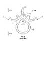
- FIG. 4is a top plan view of the disk prosthesis of FIG. 1 ;
- FIG. 5is a side sectional view of the disk prosthesis of FIG. 1 ;
- FIG. 6Ais a side sectional view of a second preferred embodiment of a disk prosthesis in accordance with the present invention.
- FIG. 6Bis a side sectional view of a third preferred embodiment of a disk prosthesis in accordance with the present invention.
- FIG. 6Cis a side sectional view of a fourth preferred embodiment of a disk prosthesis in accordance with the present invention.
- FIG. 7Ais a side elevational view of the disk prosthesis of FIG. 6A connected to a first insertion tool
- FIG. 7Bis a side elevational view of the disk prosthesis of FIG. 6A connected to a second insertion tool
- FIG. 7Cis a side elevational view of the disk prosthesis of FIG. 6A connected to a third insertion tool
- FIG. 8is a side view of the lumbar section of a human spine with a disk prosthesis shown not to scale installed between vertebra L III and vertebra L IV ;
- FIG. 9is a top sectional view of a human vertebra as is known in the art.
- FIG. 10is a side sectional view of a portion of a human spine as is known in the art.
- FIG. 11Ais a side elevational view of a fifth preferred embodiment of a disk prosthesis in accordance with the present invention.
- FIG. 11Bis a front elevational view of the disk prosthesis of FIG. 11A ;
- FIG. 12Ais a side elevational view of a sixth preferred embodiment of a disk prosthesis in accordance with the present invention.
- FIG. 12Bis a front elevational view of the disk prosthesis of FIG. 12A ;
- FIG. 13Ais a side elevational view of a seventh preferred embodiment of a disk prosthesis in accordance with the present invention.
- FIG. 13Bis a front elevational view of the disk prosthesis of FIG. 13A ;
- FIG. 14Ais a side elevational view of an eighth preferred embodiment of a disk prosthesis in accordance with the present invention.
- FIG. 14Bis a front elevational view of the disk prosthesis of FIG. 14A ;
- FIG. 15Ais a side elevational view of a fourth insertion tool for a disk prosthesis in accordance with the present invention.
- FIG. 15Bis a top plan view of the insertion tool of FIG. 15A ;
- FIG. 16Ais a side elevational view of a fifth insertion tool for a disk prosthesis in accordance with the present invention.
- FIG. 16Bis a top plan view of the insertion tool of FIG. 16A .
- FIG. 1an artificial disk or disk prosthesis 10 having a distal end 10 a , a proximal end 10 b , a lower wall 10 c , an upper wall 10 d , a first sidewall 10 e and a second sidewall 10 f ( FIGS. 3 , 4 ).
- the disk prosthesis 10includes a first part or a cap 13 .
- the cap 13includes a top 13 d , a bottom 13 c having an opening 13 f , an outer surface 13 a , and with reference to FIG.
- the disk prosthesis 10further includes a second part or a base 11 including a top 11 d , a bottom 11 c , and an outer surface 11 a .
- the outer surface 11 a proximate the bottom 11 ccontacts a concave portion 100 a of a a second vertebra 100 , and the outer surface of the base 11 proximate the top 11 d of the base 11 cooperatively engages the inner surface 13 b of the cap 13 thereby preferably allowing at least two-degrees of freedom of movement.
- the cap 13 and the base 11when inserted into an intervertebral space 121 the cap 13 and the base 11 function together as one overall device, i.e., the disk prosthesis 10 .
- the cap 13 and the base 11are preferably not mechanically connected.
- the cap 13 and the base 11are connected by a flexible structure or element (not shown) or are totally encased in a pliable, bio-compatible slip-cover or pouch (not shown).
- the inner surface 13 b and a portion 11 e of the outer surface 11 a that contacts the inner surface 13 bare preferably formed of or coated with a bio-compatible, smooth, low-friction material with high durability, such as ceramic, an alloy or the like.
- the outer surface 13 a of the cap 13 and a portion 11 b of the outer surface 11 a of the base 11 that is not covered by the cap 13comprise an outer prosthesis surface 12 that is substantially smooth over the entire surface.
- the structure of the prosthesis 10is preferably a bio-compatible metal, a bio-compatible alloy or a bio-compatible ceramic.
- the structuremay be titanium, stainless steel, alloys such as a cobalt-chrome molybdenum alloy, polymeric materials, composites, and the like without departing from the broad inventive scope of the present invention.
- the disk prosthesis 10preferably is generally ovoid or egg-shaped and symmetrical along the longer axis with rounded or contoured edges on all sides.
- the lower wall 10 c and upper wall 10 dpreferably are generally convex in order to cooperatively mate with the natural concavity of adjacent vertebrae 100 .
- the first sidewall 10 e and second sidewall 10 f of the disk prosthesis 10preferably are similarly convex for similar reasons and to facilitate installation of the disk prosthesis 10 into an intervertebral space 121 .
- the overall shape of the disk prosthesisis such that it can be inserted into an intervertebral space 121 using minimally invasive techniques through a special portal or channel allowing disk arthroplasty on an outpatient basis.
- the proximal end 10 bis rounded but more bluntly-shaped than the distal end 10 a which is sloped into a bullet-shaped tip.
- the lower wall 10 cpreferably includes a lower mesh structure 16 a and the upper wall 10 d of the disk prosthesis 10 preferably includes an upper mesh structure 16 b at the point of vertebral contact to encourage successful vertebral bone ingrowth thereby affixing the cap 13 to a first or upper vertebra 100 and the base 11 to a second or lower vertebra 100 in an adjacent pair of vertebrae 100 .
- the lower mesh structure 16 a and the upper mesh structure 16 bmay be a grid, a lattice, a plurality of perforations or apertures that extend partially through or completely through the outer surface 12 , or any other configuration capable of allowing vertebral bone ingrowth.
- the mesh structures 16 a , 16 bmay or may not be symmetrically-shaped.
- the mesh structures 16 a , 16 bare preferably identically-shaped with respect to one another and are preferably symmetrically-shaped, but need not be. It is contemplated that the mesh structures 16 a , 16 b are each a larger aperture, or alternatively, are each a generally continuous section of a bio-compatible porous material such as hydroxyapatite coated metals or an irregular metal surface coated with hydroxyapatite coating. It is further contemplated that the mesh structures 16 a , 16 b are not flush with the edges of the outer surface 12 , but are instead slightly below the edges of the outer surface 12 to allow for subsidence of the vertebrae and greater bone ingrowth.
- the length of the disk prosthesis as measured from the distal end 10 a to the proximal end 10 bis approximately 10–30 mm, depending on the particular intervertebral space 121 in which the disk prosthesis 10 is to be inserted.
- the intervertebral space between lumbar vertebra L III and lumbar vertebra L IV for an average malewould accommodate a disk prosthesis 10 of a length between approximately 25–30 mm.
- the length of the disk prosthesis 10could vary from the aforementioned range without departing from the spirit of the invention.
- the width of the disk prosthesis 10 as measured between the first sidewall 10 e and the second sidewall 10 f of the disk prosthesis 10will vary from approximately 10 mm to 25 mm depending upon the particular intervertebral space 121 in which the disk prosthesis 10 is to be inserted.
- the intervertebral space between vertebra L III and vertebra L IV in an average malewould accommodate a disk prosthesis 10 having a width of approximately 15–20 mm.
- the width of the disk prosthesis 10could vary from the aforementioned range without departing from the spirit of the invention.
- the height of the disk prosthesis 10 as measured between the upper wall 10 d and the lower wall 10 c of the disk prosthesis 10will vary from approximately 5 mm to 25 mm depending upon the particular intervertebral space 121 in which the disk prosthesis 10 is to be inserted.
- the intervertebral space between vertebra L III and vertebra L IV in an average malewould accommodate a disk prosthesis 10 having a height of approximately 8–16 mm.
- the height of the disk prosthesis 10could vary from the aforementioned range without departing from the spirit of the invention.
- FIG. 5shows a side sectional view of the disk prosthesis 10 as viewed from lines 5 — 5 of FIG. 4 .
- FIG. 5more clearly shows the cooperative interaction between the cap 13 and the base 11 .
- a portion 11 e of the outer surface 11 a of the base 11 proximate the top 11 d of the base 11cooperatively engages the inner surface 13 b of the cap 13 thereby allowing at least two-degrees of freedom of movement. Motion allowed includes rotation (roll) and tilting or angulation (pitch) in any direction, but not motion in the plane from front to back or side to side (i.e., parallel to the disk space).
- the inner surface 13 b and the portion 11 e of the outer surface 11 a that contacts the inner surface 13 bare generally concealed.
- the overall shape of the disk prosthesis 10is designed for insertion using minimally invasive techniques through a special portal or channel allowing a replacement procedure to be implemented on an outpatient basis.
- the convex and contoured shape of the disk prosthesis 10will allow the disk prosthesis 10 to be driven into an intervertebral disk space 121 by merely temporarily distracting the vertebrae with minimal removal of the vertebral rim or annulus (not shown clearly) at the point of entry, thereby reducing the chance of dislodging the device post-surgery.
- the smooth contour and edges of the disk prosthesis 10provide for a safe and easy entrance into the intervertebral space 121 .
- the disk prosthesis 10is a self centering device. Due largely to the shape of the disk prosthesis 10 , the disk prosthesis 10 will tend to find the natural concavity of adjacent vertebrae 100 . As such, placement of the disk prosthesis 10 is much faster than that of prior art intervertebral disk replacement devices, thereby effectively reducing the duration of an intervertebral disk replacement procedure and the associated risks therewith.
- the self-centering feature of the disk prosthesis 10will allow rapid settling of the disk prosthesis 10 into adjacent vertebral bone to promote rapid bone ingrowth while retention of most of the annulus and peripheral rim of the vertebrae 100 would provide good load sharing support to prevent excessive subsidence, where subsidence is the natural settling of intervertebral matter into a softer central portion of the vertebral bodies 106 .
- FIG. 8shows a side view of the lumbar region 122 of a portion of a human spine 120 .
- the disk prosthesis 10 in accordance with the first preferred embodiment of the present inventionis shown installed between lumbar vertebra L III and lumbar vertebra L IV .
- the second sidewall 10 f of the disk prosthesis 10is placed on the anterior side of the L III –L IV intervertebral space
- the first sidewall 10 e of the disk prosthesis 10is placed closest to the posterior side of the L III –L IV intervertebral space
- the upper wall 10 d of the disk prosthesis 10is adjacent to vertebra L III
- the lower wall 10 c of the disk prosthesis 10is adjacent to vertebra L IV .
- the surgeonwould have inserted the distal end 10 a of the disk prosthesis 10 into the gap between the L III –L IV vertebrae as depicted in FIG. 9 by a directional arrow D. It is just as likely and possible for the surgeon to place the distal end 10 a of the disk prosthesis 10 through the space between the L III –L IV vertebrae in the direction of a directional arrow C ( FIG. 9 ) or from any other direction.
- FIG. 6Ashows a side sectional view of a second preferred embodiment of a disk prosthesis 60 in accordance with the present invention.
- the disk prosthesis 60has a distal end 60 a , a proximal end 60 b , a lower wall 60 c , an upper wall 60 d , a first sidewall 60 e ( FIGS. 7A–7C ), and a second sidewall (not shown).
- the disk prosthesisincludes a first part or a cap 63 .
- the cap 63includes a top 63 d , a bottom 63 c having an opening 63 f , an outer surface 63 a , an inner surface 63 b and a socket 63 e extending into an interior of the cap 63 from the opening and defined by the inner surface 63 b .
- the outer surface 63 a proximate the top 63 dcontacts a concave portion 100 b of a first vertebra 100 .
- the disk prosthesis 60further includes a second part or a base 61 including a top 61 d , a bottom 61 c , and an outer surface 61 a .
- the outer surface 61 a proximate the bottom 61 ccontacts a concave portion 100 a of a second vertebra 100 , and the outer surface 61 a of the base 61 proximate the top 61 d of the base 61 cooperatively engages the inner surface 63 b of the cap 63 thereby allowing at least two-degrees of freedom of movement.
- the cap 63 and the base 61When inserted into an intervertebral space 121 the cap 63 and the base 61 function together as one overall device, i.e., the disk prosthesis 60 .
- the cap 63 and the base 61are preferably not mechanically connected.
- the base 61is preferably not retained in the cap 63 , but could be.
- the cap 63 and the base 61are connected by a flexible structure or element (not shown) or are totally encased in a pliable, bio-compatible slip-cover or pouch (not shown).
- the inner surface 63 b and a portion 61 e of the outer surface 61 a that contacts the inner surface 63 bare preferably formed of or coated with a bio-compatible, smooth, low-friction material with high durability, such as a ceramic, an alloy or the like.
- the top 61 d of the base 61includes a spherically or hemispherically-shaped portion or a ball 61 f .
- the ball 61 f of the base 61cooperatively engages the socket 63 e of the cap 63 thereby mimicking a ball and socket joint such as a hip-joint.
- other iterations and combinations of mutually cooperating engagement designs providing relative movementcould be implemented without departing from the broad general scope of the present invention.
- the lower wall 60 cincludes a lower mesh structure 66 a and the upper wall 60 d of the disk prosthesis 60 includes an upper mesh structure 66 b at the point of vertebral contact to encourage successful vertebral bone ingrowth thereby affixing the cap 63 to a first or upper vertebra 100 and the base 61 to a second or lower vertebra 100 in an adjacent pair of vertebrae 100 .
- the lower mesh 66 a and the upper mesh 66 bmay have the attributes of the lower mesh 16 a and the upper mesh 16 b discussed above with reference to the first preferred embodiment.
- FIG. 6Bshows a side sectional view of a third preferred embodiment of a disk prosthesis 70 in accordance with the present invention.
- the disk prosthesis 70has a distal end 70 a , a proximal end 70 b , a lower wall 70 c , an upper wall 70 d , a first sidewall (not shown), and a second sidewall (not shown).
- the disk prosthesisincludes a first part or a cap 73 .
- the cap 73includes a top 73 d , a bottom 73 c having an opening 73 f , an outer surface 73 a , an inner surface 73 b and a socket 73 e extending into an interior of the cap 73 from the opening and defined by the inner surface 73 b .
- the outer surface 73 a proximate the top 73 dcontacts a concave portion 100 b of a first vertebra 100 .
- the disk prosthesis 70further includes a second part or a base 71 including a top 71 d , a bottom 71 c , and an outer surface 71 a .
- the outer surface 71 a proximate the bottom 71 ccontacts a concave portion 100 a of a second vertebra 100
- the outer surface 71 a of the base 71 proximate the top 71 d of the base 71cooperatively engages the inner surface 73 b of the cap 73 thereby allowing at least two-degrees of freedom of movement.
- the cap 73 and the base 71When inserted into an intervertebral space 121 the cap 73 and the base 71 function together as one overall device, i.e., the disk prosthesis 70 .
- the cap 73 and the base 71are preferably not mechanically connected.
- the base 71is preferably not retained in the cap 73 , but could be.
- the cap 73 and the base 71are connected by a flexible structure or element (not shown) or are totally encased in a pliable, bio-compatible slip-cover or pouch (not shown).
- the inner surface 73 b and a portion 71 e of the outer surface 71 a that contacts the inner surface 73 bare preferably formed of or coated with a bio-compatible, smooth, low-friction material with high durability, such as a ceramic, an alloy or the like.
- the top 71 d of the base 71includes a spherically or hemispherically-shaped portion or a ball 71 f .
- the ball 71 f of the base 71cooperatively engages the socket 73 e of the cap 73 thereby mimicking a ball and shallow socket joint such as a shoulder-joint.
- other iterations and combinations of mutually cooperating engagement designs providing relative movementcould be implemented without departing from the broad general scope of the present invention.
- the lower wall 70 cincludes a lower mesh structure 76 a and the upper wall 70 d of the disk prosthesis 70 includes an upper mesh structure 76 b at the point of vertebral contact to encourage successful vertebral bone ingrowth thereby affixing the cap 73 to a first or upper vertebra 100 and the base 71 to a second or lower vertebra 100 in an adjacent pair of vertebrae 100 .
- the lower mesh 76 a and the upper mesh 76 bmay have the attributes of the lower mesh 16 a and the upper mesh 16 b discussed above with reference to the first preferred embodiment.
- FIG. 6Cshows a side sectional view of a fourth preferred embodiment of a disk prosthesis 80 in accordance with the present invention.
- the disk prosthesis 80has a distal end 80 a , a proximal end 80 b , a lower wall 80 c , an upper wall 80 d , a first sidewall (not shown), and a second sidewall (not shown).
- the disk prosthesisincludes a first part or a cap 83 .
- the cap 83includes a top 83 d , a bottom 83 c having an opening 83 f , an outer surface 83 a , an inner surface 83 b and a socket 83 e extending into an interior of the cap 83 from the opening and defined by the inner surface 83 b .
- the outer surface 83 a proximate the top 83 dcontacts a concave portion 100 b of a first vertebra 100 .
- the disk prosthesis 80further includes a second part or a base 81 including a top 81 d , a bottom 81 c , and an outer surface 81 a .
- the outer surface 81 a proximate the bottom 81 ccontacts a concave portion 100 a of a second vertebra 100
- the outer surface 81 a of the base 81 proximate the top 81 d of the base 81cooperatively engages the inner surface 83 b of the cap 83 thereby allowing at least two-degrees of freedom of movement.
- the cap 83 and the base 81When inserted into an intervertebral space 121 the cap 83 and the base 81 function together as one overall device, i.e., the disk prosthesis 80 .
- the cap 83 and the base 81are preferably not mechanically connected.
- the base 81is preferably not retained in the cap 83 , but could be.
- the cap 83 and the base 81are connected by a flexible structure or element (not shown) or are totally encased in a pliable, bio-compatible slip-cover or pouch (not shown).
- the inner surface 83 b and a portion 81 e of the outer surface 81 a that contacts the inner surface 83 bare preferably formed of or coated with a bio-compatible, smooth, low-friction material with high durability, such as a ceramic, an alloy or the like.
- the top 81 d of the base 81includes a spherically or hemispherically-shaped portion or a ball 81 f .
- the ball 81 f of the base 81cooperatively engages the socket 83 e of the cap 83 thereby mimicking a ball and shallow socket joint such as a shoulder-joint.
- other iterations and combinations of mutually cooperating engagement designs providing relative movementcould be implemented without departing from the broad general scope of the present invention.
- the lower wall 80 cincludes a lower mesh structure 86 a and the upper wall 80 d of the disk prosthesis 80 includes an upper mesh structure 86 b at the point of vertebral contact to encourage successful vertebral bone ingrowth thereby affixing the cap 83 to a first or upper vertebra 100 and the base 81 to a second or lower vertebra 100 in an adjacent pair of vertebrae 100 .
- the lower mesh 86 a and the upper mesh 86 bmay have the attributes of the lower mesh 16 a and the upper mesh 16 b discussed above with reference to the first preferred embodiment.
- FIG. 7Ashows the disk prosthesis 60 of the second preferred embodiment with a specially designed first insertion tool 18 having a handle 18 a and a plurality of resilient grasping fingers 19 .
- the grasping fingers 19are actuated to grasp and hold the disk prosthesis 60 by moving a tool actuation stem 17 proximally and to open and release the disk prosthesis 60 by moving the tool actuation stem 17 distally.
- the handle 18 a of the first insertion tool 18may be formed of any substantially rigid material, but preferably is formed of a material that is bio-compatible such as titanium, stainless steel, or of a bio-compatible alloy, composite, polymeric material or the like.
- the grasping fingers 19are preferably formed of a resilient, bio-compatible synthetic or polymeric material. It is contemplated that the grasping fingers 19 are biased by either their own resiliency or by other resilient means (not shown) such as coil springs in order to allow the grasping fingers 19 to grasp the disk prosthesis 60 without actuation but to be capable of releasing the disk prosthesis by merely twisting or moving the first insertion tool 18 proximally at a slight angle.
- FIG. 7Bshows the disk prosthesis 60 of the second preferred embodiment with a specially designed second insertion tool 22 having a handle 22 a and a suction cup 23 .
- the handle 22 a of the second insertion tool 22may be formed of any substantially rigid material, but preferably is formed of a material that is bio-compatible such as titanium, stainless steel, or of a bio-compatible alloy, composite, polymeric material or the like. It should be noted that the material of construction of the handle 22 a of the second insertion tool 22 could be any material without diverging from the broad scope of the present invention.
- the suction cup 23is preferably formed of a resilient, bio-compatible synthetic or polymeric material.
- the suction cup 23is biased inwardly by its own resiliency in order to allow the suction cup 23 to grasp the disk prosthesis 60 without actuation but to be capable of releasing the disk prosthesis by merely twisting or moving the second insertion tool 22 proximally at a slight angle.
- FIG. 7Cshows the disk prosthesis 60 of the second preferred embodiment with a specially designed third insertion tool 20 having a handle 20 a and being threaded into a socket 64 with female threads 64 a by male threads 20 b of the third insertion tool 20 .
- the handle 20 a of the third insertion tool 20may be formed of any substantially rigid material, but preferably is formed of a material that is bio-compatible such as titanium, stainless steel, or of a bio-compatible alloy, composite, polymeric material or the like. It should be noted that the material of construction of the third insertion tool 20 could be any material without diverging from the broad scope of the present invention. Design of insertion tools are not critical to the present invention, and a variety of tool designs are contemplated for use with various disk prostheses.
- FIGS. 11A–11Bshow a fifth preferred embodiment of a disk prosthesis in accordance with the present invention.
- the disk prosthesis 90has a distal end 90 a , a proximal end 90 b , a lower wall 90 c , an upper wall 90 d , a first sidewall (not shown), and a second sidewall (not shown).
- the disk prosthesisincludes a first part or a cap 93 .
- the cap 93includes a top 93 d , a bottom 93 c having an opening 93 f , an outer surface 93 a , an inner surface 93 b and a socket 93 e extending into an interior of the cap 93 from the opening and defined by the inner surface 93 b .
- the outer surface 93 a proximate the top 93 dcontacts a concave portion 100 b of a first vertebra 100 .
- the disk prosthesis 90further includes a second part or a base 91 including a top 91 d , a bottom 91 c , and an outer surface 91 a .
- the outer surface 91 a proximate the bottom 91 ccontacts a concave portion 100 a of a second vertebra 100
- the outer surface 91 a of the base 91 proximate the top 91 d of the base 91cooperatively engages the inner surface 93 b of the cap 93 thereby allowing at least two-degrees of freedom of movement.
- the cap 93is preferably slightly smaller than the base 91 in both length and width in order to allow freedom movement even when bone growth reaches near the edges of the cap 93 and/or base 91 .
- the base 91may be slightly smaller than the cap 93 for similar reasons without departing from the present invention.
- the disk prosthesis 90includes at least one upper arch 150 and at least one lower arch 152 , but preferably the disk prosthesis 90 includes three upper arches 150 and three lower arches 152 .
- the arches 150 , 152are generally disposed symmetrically along and about a centerline of the longer axis of the disk prosthesis 90 and are secured to the body of the disk prosthesis 90 .
- the arches 150 , 152may be secured to the disk prosthesis 90 by other means and may be disposed in other orientations without departing from the spirit of the present invention.
- the arches 150 , 152protrude above the top and bottom 190 d , 190 c of the disk prosthesis 90 , respectively.
- the arches 150 , 152are configured to settle into bone matter, and therefore, the arches 150 , 152 have sharpened edges 150 a , 152 a .
- the sharpened edges 150 a , 152 amay include serrations, pins, sharpened cones or a simple knife-like edge, but need not be.
- the sharpened edges 150 a , 152 aare partially knife like proximate the ends of the arches and partially covered with sharpened cones 153 .
- the arches 150 , 152are preferably about 0.5 mm to about 2.0 mm wide.
- the arches 150 , 152also serve to center the disk prosthesis 90 during placement and prevent the disk prosthesis 90 from rolling or canting thereafter.
- FIGS. 12A–12Bshow a sixth preferred embodiment of a disk prosthesis 190 in accordance with the present invention.
- the disk prosthesis 190has a distal end 190 a , a proximal end 190 b , a lower wall 190 c , an upper wall 190 d , a first sidewall 190 e , and a second sidewall 190 f .
- the disk prosthesisincludes a first part or a cap 193 .
- the cap 193includes a top 193 d , a bottom 193 c having an opening 193 f , an outer surface 193 a , an inner surface (not shown) and a socket (not shown) extending into an interior of the cap 193 from the opening and defined by the inner surface.
- the outer surface 193 a proximate the top 193 dcontacts a concave portion 100 b of a first vertebra 100 .
- the disk prosthesis 190further includes a second part or a base 191 including a top 191 d , a bottom 191 c , and an outer surface 191 a .
- the disk prosthesis 190includes at least one upper arch 150 and at least one lower arch 152 , but preferably the disk prosthesis 190 includes three upper arches 150 and three lower arches 152 similar to the disk prosthesis 90 .
- the arches 150 , 152are generally disposed symmetrically along and about a centerline of the longer axis of the disk prosthesis 190 and are secured to the body of the disk prosthesis 190 .
- the top of the cap 193has a recess and the bottom of the base 191 has a recess, the recesses include a platform 193 h and 191 h , respectively.
- the platforms 191 h , 193 hare preferably are texturized and/or coated with a material to promote bone growth.
- FIGS. 13A–13Bshow a seventh preferred embodiment of a disk prosthesis 290 in accordance with the present invention.
- the disk prosthesis 290has a distal end 290 a , a proximal end 290 b , a lower wall 290 c , an upper wall 290 d , a first sidewall 290 e , and a second sidewall 290 f .
- the disk prosthesisincludes a first part or a cap 293 .
- the cap 293includes a top 293 d , a bottom 293 c having an opening 293 f , an outer surface 293 a , an inner surface (not shown) and a socket (not shown) extending into an interior of the cap 293 from the opening and defined by the inner surface.
- the disk prosthesis 290further includes a second part or a base 291 including a top 291 d , a bottom 291 c , and an outer surface 291 a .
- the disk prosthesis 290includes at least one upper arch 150 and at least one lower arch 152 , but preferably the disk prosthesis 290 includes three upper arches 150 and three lower arches 152 similar to the disk prosthesis 90 .
- the arches 150 , 152are generally disposed symmetrically along and about a centerline of the longer axis of the disk prosthesis 290 and are secured to the body of the disk prosthesis 290 .
- the top of the cap 293 and the bottom of the base 291are preferably flatly shaped.
- the flat surfacespreferably are texturized and/or coated with a material to promote bone growth.
- FIGS. 14A–14Bshow an eighth preferred embodiment of a disk prosthesis 390 in accordance with the present invention.
- the disk prosthesis 390has a distal end 390 a , a proximal end 390 b , a lower wall 390 c , an upper wall 390 d , a first sidewall 390 e , and a second sidewall 390 f .
- the disk prosthesisincludes a first part or a cap 393 .
- the cap 393includes a top 393 d , a bottom 393 c , an outer surface 393 a , an inner surface (not shown) and a socket (not shown) extending into an interior of the cap 393 from the opening and defined by the inner surface 393 b .
- the outer surface 393 a proximate the top 393 dcontacts a concave portion 100 b of a first vertebra 100 .
- the disk prosthesis 390further includes a second part or a base 391 including a top 391 d , a bottom 391 c , and an outer surface 391 a .
- the outer surface 391 a proximate the bottom 391 ccontacts a concave portion 100 a of a second vertebra 100
- the outer surface 391 a of the base 391 proximate the top 391 d of the base 391cooperatively engages the inner surface (not shown) of the cap 393 thereby allowing at least two-degrees of freedom of movement.
- the disk prosthesis 390includes at least one row of sharpened cones 153 on the top of the cap 393 and at least one row of sharpened cones 153 on the bottom of the base 391 , but preferably the disk prosthesis 390 includes three rows of sharpened cones 153 on the top of the cap 393 and three rows of sharpened cones 153 on the bottom of the base 391 .
- the rows of sharpened cones 153are generally disposed symmetrically along and about a centerline of the longer axis of the disk prosthesis 390 and are secured to the body of the disk prosthesis 390 .
- the top of the cap 393 and the bottom of the base 391are preferably convexly shaped to more readily find the contours of the concave portions 100 a , 100 b of adjacent vertebrae 100 .
- the surface of the disk prosthesis 390 proximate the rows of sharpened cones 153is texturized and/or coated with a material to promote bone growth such as hydroxyapatite.
- FIGS. 15A–15Bshow a fourth insertion tool 220 for a disk prosthesis 10 ( 60 , 70 , or 80 ) having lower and upper openings 16 a , 16 b ( 66 a , 66 b , 76 a , 76 b , 86 a , 86 b ), respectively.
- the insertion tool 220has a first finger 224 configured to cooperatively engage the lower opening 16 a and a second finger 222 configured to cooperatively engage the upper opening 16 b .
- the fingers 222 , 224have outer surfaces which are shaped to match the contoured shape of the disk prosthesis 10 to allow a smooth insertion of the disk prosthesis 10 .
- the fingers 222 , 224also prevent foreign matter and debris from getting caught in the openings 16 a , 16 b during insertion. Because the fingers 222 , 224 grasp the disk prosthesis 10 in a specific orientation defined by the upper and lower openings 16 a , 16 b , the insertion tool 220 provides the surgeon with means to orient the disk prosthesis 10 correctly during insertion.
- the insertion tool 220further includes a driving member 226 that is configured to engage the body of the disk prosthesis 10 .
- the driving member 226is configured to be impacted such that during insertion a surgeon may tap or hammer the driving member 226 to push the disk prosthesis 10 through a small opening.
- the first and second fingers 222 , 224are retractable relative to the driving member 226 .
- the disk prosthesis 10may have grooves 166 (shown in phantom in FIG.
- the insertion tool 220includes third and fourth fingers 228 (shown in phantom in FIGS. 15A–15B ) configured to retractably move along the space between the upper part 13 and the lower part 11 of the body of the disk prosthesis 10 .
- FIGS. 16A–16Bis a side elevational view of a fifth insertion tool 230 for a disk prosthesis 90 ( 190 , 290 or 390 ) having upper and lower openings 96 a , 96 b and upper and lower arches 150 , 152 .
- the upper finger 232has first and second prongs 232 a , 232 b for straddling the upper arches 150 as best seen in FIG. 16B .
- the insertion tool 230is similar to the insertion tool 220 , but each of the retractable fingers 232 , 234 is forked to accommodate the arches 150 , 152 .
- the arches 150 , 152 and the rows of cones 153are just below the outer surface of the fingers 232 , 234 , so that the arches 150 , 152 do not injure adjacent tissue during insertion.
- the insertion tool 230includes third and fourth fingers 238 (shown in phantom in FIGS. 16A–16B ) configured to retractably move between the space between the upper part 93 and the lower part 91 of the body of the disk prosthesis 90 .
- each of the retractable fingers 232 , 234in order to accommodate multiple arches 150 , 152 (such as on disk prostheses 190 and 290 ) and multiple rows of sharpened cones 153 (such as on disk prosthesis 390 ).
- the intervertebral disk prostheses 10 , 60 , 70 , 90 , 190 , 290 and 390have a freedom of movement that is limited to between about 2–15 degrees tilt in any direction.
- the annular ligament of a human beingis built for physiologic limiting thereby stopping over rotation.
- the facets in the lumbar regionalso limit rotation and tilt.
Landscapes
- Health & Medical Sciences (AREA)
- Engineering & Computer Science (AREA)
- Biomedical Technology (AREA)
- Orthopedic Medicine & Surgery (AREA)
- Transplantation (AREA)
- Neurology (AREA)
- Heart & Thoracic Surgery (AREA)
- Oral & Maxillofacial Surgery (AREA)
- Cardiology (AREA)
- Vascular Medicine (AREA)
- Life Sciences & Earth Sciences (AREA)
- Animal Behavior & Ethology (AREA)
- General Health & Medical Sciences (AREA)
- Public Health (AREA)
- Veterinary Medicine (AREA)
- Physical Education & Sports Medicine (AREA)
- Prostheses (AREA)
- Materials For Medical Uses (AREA)
- Surgical Instruments (AREA)
Abstract
Description
Claims (20)
Priority Applications (3)
| Application Number | Priority Date | Filing Date | Title |
|---|---|---|---|
| US10/345,634US7011684B2 (en) | 2002-01-17 | 2003-01-16 | Intervertebral disk prosthesis |
| US10/951,317US7740658B2 (en) | 2002-01-17 | 2004-09-27 | Intervertebral disk prosthesis methods of use |
| US11/370,537US20060155378A1 (en) | 2002-01-17 | 2006-03-08 | Intervertebral disk prosthesis |
Applications Claiming Priority (3)
| Application Number | Priority Date | Filing Date | Title |
|---|---|---|---|
| US34974302P | 2002-01-17 | 2002-01-17 | |
| US36966702P | 2002-04-02 | 2002-04-02 | |
| US10/345,634US7011684B2 (en) | 2002-01-17 | 2003-01-16 | Intervertebral disk prosthesis |
Related Child Applications (2)
| Application Number | Title | Priority Date | Filing Date |
|---|---|---|---|
| US10/951,317DivisionUS7740658B2 (en) | 2002-01-17 | 2004-09-27 | Intervertebral disk prosthesis methods of use |
| US11/370,537DivisionUS20060155378A1 (en) | 2002-01-17 | 2006-03-08 | Intervertebral disk prosthesis |
Publications (2)
| Publication Number | Publication Date |
|---|---|
| US20030135278A1 US20030135278A1 (en) | 2003-07-17 |
| US7011684B2true US7011684B2 (en) | 2006-03-14 |
Family
ID=27616749
Family Applications (3)
| Application Number | Title | Priority Date | Filing Date |
|---|---|---|---|
| US10/345,634Expired - LifetimeUS7011684B2 (en) | 2002-01-17 | 2003-01-16 | Intervertebral disk prosthesis |
| US10/951,317Active2025-12-23US7740658B2 (en) | 2002-01-17 | 2004-09-27 | Intervertebral disk prosthesis methods of use |
| US11/370,537AbandonedUS20060155378A1 (en) | 2002-01-17 | 2006-03-08 | Intervertebral disk prosthesis |
Family Applications After (2)
| Application Number | Title | Priority Date | Filing Date |
|---|---|---|---|
| US10/951,317Active2025-12-23US7740658B2 (en) | 2002-01-17 | 2004-09-27 | Intervertebral disk prosthesis methods of use |
| US11/370,537AbandonedUS20060155378A1 (en) | 2002-01-17 | 2006-03-08 | Intervertebral disk prosthesis |
Country Status (7)
| Country | Link |
|---|---|
| US (3) | US7011684B2 (en) |
| EP (1) | EP1471855B1 (en) |
| JP (1) | JP2005515002A (en) |
| AT (1) | ATE493093T1 (en) |
| AU (1) | AU2003210569A1 (en) |
| DE (1) | DE60335519D1 (en) |
| WO (1) | WO2003061364A2 (en) |
Cited By (60)
| Publication number | Priority date | Publication date | Assignee | Title |
|---|---|---|---|---|
| US20040034422A1 (en)* | 2001-07-16 | 2004-02-19 | Errico Joseph P. | Intervertebral spacer device having a circumferentially buried wire mesh endplate attachment device |
| US20040153158A1 (en)* | 2001-07-16 | 2004-08-05 | Errico Joseph P. | Intervertebral spacer device having an angled perimeter for manipulation using a surgical tool |
| US20040167536A1 (en)* | 2001-07-16 | 2004-08-26 | Errico Joseph P. | Instrumentation for properly seating an artificial intervertebral disc in an intervertebral space |
| US20050043798A1 (en)* | 2002-01-17 | 2005-02-24 | Concept Matrix, Llc | Intervertebral disk prosthesis methods of use |
| US20060136063A1 (en)* | 2004-12-22 | 2006-06-22 | Ldr Medical | Intervertebral disc prosthesis |
| US20060200236A1 (en)* | 2005-03-04 | 2006-09-07 | Regeneration Technologies, Inc. | Intermediate bone block and its use in bone block assemblies and assembled bone-tendon-bone grafts |
| US20060212036A1 (en)* | 2005-03-04 | 2006-09-21 | Regeneration Technologies, Inc. | Bone block assemblies and their use in assembled bone-tendon-bone grafts |
| US20070123906A1 (en)* | 2001-07-16 | 2007-05-31 | Spinecore, Inc. | Inserter/impactor for implanting an artificial intervertebral disc |
| US20070156243A1 (en)* | 2001-07-16 | 2007-07-05 | Spinecore, Inc. | Intervertebral spacer device having engagement hole pairs |
| US20070162130A1 (en)* | 2005-11-30 | 2007-07-12 | Ralph Rashbaum | Intervertebral disc prosthesis and instrumentation for insertion of the prosthesis between the vertebrae |
| US20070162139A1 (en)* | 2001-07-16 | 2007-07-12 | Ralph James D | Trial intervertebral distraction spacers |
| USD552734S1 (en)* | 2003-01-16 | 2007-10-09 | Concept Matrix, Llc | Vertebral defect device |
| USD557417S1 (en)* | 2003-01-16 | 2007-12-11 | Concept Matrix, Llc | Disk prosthesis |
| US20080154382A1 (en)* | 2004-08-06 | 2008-06-26 | Spinalmotion, Inc. | Methods and Apparatus for Intervertebral Disc Prosthesis Insertion |
| USD572364S1 (en)* | 2006-02-15 | 2008-07-01 | Transoma Medical, Inc. | Implantable housing |
| US20080183292A1 (en)* | 2007-01-29 | 2008-07-31 | Warsaw Orthopedic, Inc. | Compliant intervertebral prosthetic devices employing composite elastic and textile structures |
| US20080215155A1 (en)* | 2003-05-27 | 2008-09-04 | Spinalmotion, Inc. | Intervertebral prosthetic disc |
| US20080234686A1 (en)* | 2001-05-04 | 2008-09-25 | Jacques Beaurain | Intervertebral disc prosthesis, surgical methods, and fitting tools |
| US20080249629A1 (en)* | 2002-01-17 | 2008-10-09 | Concept Matrix Llc | Vertebral defect device |
| USD583054S1 (en)* | 2005-03-04 | 2008-12-16 | Rti Biologics, Inc. | Set of orthopedic bone block assembly |
| US20090011323A1 (en)* | 2007-07-05 | 2009-01-08 | General Electric Company | Solid Oxide Electrochemical Devices Having an Improved Electrode |
| US20090105833A1 (en)* | 2007-10-22 | 2009-04-23 | Spinalmotion, Inc. | Method and Spacer Device for Spanning a Space Formed upon Removal of an Intervertebral Disc |
| US20090157188A1 (en)* | 2004-04-28 | 2009-06-18 | Ldr Medical | Intervertebral Disc Prosthesis |
| US20090210060A1 (en)* | 2004-07-30 | 2009-08-20 | Spinalmotion, Inc. | Intervertebral Prosthetic Disc With Metallic Core |
| US20090216330A1 (en)* | 2004-09-23 | 2009-08-27 | Christophe Geisert | System and method for an intervertebral implant |
| US20090216241A1 (en)* | 2005-06-29 | 2009-08-27 | Ldr Medical | Instrumentation and Methods for Inserting an Intervertebral Disc Prosthesis |
| US20090234458A1 (en)* | 2008-03-11 | 2009-09-17 | Spinalmotion, Inc. | Artificial Intervertebral Disc With Lower Height |
| US20090270870A1 (en)* | 2008-04-24 | 2009-10-29 | Rafail Zubok | Dynamic distractor |
| US20090270986A1 (en)* | 2005-12-08 | 2009-10-29 | Fbcdevice Aps | Disc Implant |
| US20090312765A1 (en)* | 2001-07-16 | 2009-12-17 | Spinecore, Inc. | Wedge Ramp Distractor for use in Implanting Artificial Intervertebral Discs |
| US20100049040A1 (en)* | 2003-01-31 | 2010-02-25 | Spinalmotion, Inc. | Spinal Midline Indicator |
| US7727278B2 (en) | 2005-03-04 | 2010-06-01 | Rti Biologics, Inc. | Self fixing assembled bone-tendon-bone graft |
| US20100262240A1 (en)* | 2007-11-16 | 2010-10-14 | Kris Chavatte | Porous containment device and associated method for stabilization of vertebral compression fractures |
| US20100262242A1 (en)* | 2009-04-09 | 2010-10-14 | Kris Chavatte | Minimally invasive spine augmentation and stabilization system and method |
| US7842088B2 (en) | 2005-09-23 | 2010-11-30 | Ldr Medical | Intervertebral disc prosthesis |
| USD630329S1 (en) | 2007-02-12 | 2011-01-04 | Rti Biologics, Inc. | Orthopedic bone block assembly |
| US20110046744A1 (en)* | 2001-07-16 | 2011-02-24 | Spinecore, Inc. | Intervertebral spacer device having recessed notch pairs for manipulation using a surgical tool |
| US8029568B2 (en) | 2001-10-18 | 2011-10-04 | Spinecore, Inc. | Intervertebral spacer device having a slotted partial circular domed arch strip spring |
| US8083797B2 (en) | 2005-02-04 | 2011-12-27 | Spinalmotion, Inc. | Intervertebral prosthetic disc with shock absorption |
| US8092539B2 (en) | 2001-10-01 | 2012-01-10 | Spinecore, Inc. | Intervertebral spacer device having a belleville washer with concentric grooves |
| US8167886B2 (en) | 2002-01-17 | 2012-05-01 | Concept Matrix, Llc | Insertion tool for a vertebral defect device |
| US8206449B2 (en) | 2008-07-17 | 2012-06-26 | Spinalmotion, Inc. | Artificial intervertebral disc placement system |
| US8267999B2 (en) | 2002-11-05 | 2012-09-18 | Ldr Medical | Intervertebral disc prosthesis |
| US8343219B2 (en) | 2007-06-08 | 2013-01-01 | Ldr Medical | Intersomatic cage, intervertebral prosthesis, anchoring device and implantation instruments |
| US8465546B2 (en) | 2007-02-16 | 2013-06-18 | Ldr Medical | Intervertebral disc prosthesis insertion assemblies |
| US8470038B2 (en) | 2005-03-04 | 2013-06-25 | Rti Biologics, Inc. | Adjustable and fixed assembled bone-tendon-bone graft |
| US8486147B2 (en) | 2006-04-12 | 2013-07-16 | Spinalmotion, Inc. | Posterior spinal device and method |
| US8506631B2 (en) | 2007-08-09 | 2013-08-13 | Spinalmotion, Inc. | Customized intervertebral prosthetic disc with shock absorption |
| US8845730B2 (en) | 2008-07-18 | 2014-09-30 | Simplify Medical, Inc. | Posterior prosthetic intervertebral disc |
| US8858635B2 (en) | 2004-02-04 | 2014-10-14 | Ldr Medical | Intervertebral disc prosthesis |
| US9011544B2 (en) | 2008-05-05 | 2015-04-21 | Simplify Medical, Inc. | Polyaryletherketone artificial intervertebral disc |
| US9034038B2 (en) | 2008-04-11 | 2015-05-19 | Spinalmotion, Inc. | Motion limiting insert for an artificial intervertebral disc |
| US9220603B2 (en) | 2008-07-02 | 2015-12-29 | Simplify Medical, Inc. | Limited motion prosthetic intervertebral disc |
| US9402745B2 (en) | 2003-01-31 | 2016-08-02 | Simplify Medical, Inc. | Intervertebral prosthesis placement instrument |
| US9539041B2 (en) | 2013-09-12 | 2017-01-10 | DePuy Synthes Products, Inc. | Minimally invasive biomaterial injection system |
| US9655741B2 (en) | 2003-05-27 | 2017-05-23 | Simplify Medical Pty Ltd | Prosthetic disc for intervertebral insertion |
| US9693874B2 (en) | 2013-03-15 | 2017-07-04 | Blackstone Medical, Inc. | Composite spinal interbody device and method |
| US10603185B2 (en) | 2004-02-04 | 2020-03-31 | Ldr Medical | Intervertebral disc prosthesis |
| US11197765B2 (en) | 2019-12-04 | 2021-12-14 | Robert S. Bray, Jr. | Artificial disc replacement device |
| US11839554B2 (en) | 2020-01-23 | 2023-12-12 | Robert S. Bray, Jr. | Method of implanting an artificial disc replacement device |
Families Citing this family (61)
| Publication number | Priority date | Publication date | Assignee | Title |
|---|---|---|---|---|
| US7235081B2 (en)* | 2001-07-16 | 2007-06-26 | Spinecore, Inc. | Wedge plate inserter/impactor and related methods for use in implanting an artificial intervertebral disc |
| US20030069642A1 (en)* | 2001-10-04 | 2003-04-10 | Ralph James D. | Artificial intervertebral disc having a flexible wire mesh vertebral body contact element |
| US20070198092A1 (en)* | 2001-07-16 | 2007-08-23 | Spinecore, Inc. | System for inserting artificial intervertebral discs |
| US7713302B2 (en) | 2001-10-01 | 2010-05-11 | Spinecore, Inc. | Intervertebral spacer device utilizing a spirally slotted belleville washer having radially spaced concentric grooves |
| US8038713B2 (en) | 2002-04-23 | 2011-10-18 | Spinecore, Inc. | Two-component artificial disc replacements |
| US20080027548A9 (en) | 2002-04-12 | 2008-01-31 | Ferree Bret A | Spacerless artificial disc replacements |
| US6706068B2 (en) | 2002-04-23 | 2004-03-16 | Bret A. Ferree | Artificial disc replacements with natural kinematics |
| US7066958B2 (en)* | 2002-05-10 | 2006-06-27 | Ferree Bret A | Prosthetic components with partially contained compressible resilient members |
| US8388684B2 (en) | 2002-05-23 | 2013-03-05 | Pioneer Signal Technology, Inc. | Artificial disc device |
| US7001433B2 (en) | 2002-05-23 | 2006-02-21 | Pioneer Laboratories, Inc. | Artificial intervertebral disc device |
| US6770095B2 (en)* | 2002-06-18 | 2004-08-03 | Depuy Acroned, Inc. | Intervertebral disc |
| US6908484B2 (en) | 2003-03-06 | 2005-06-21 | Spinecore, Inc. | Cervical disc replacement |
| US7985255B2 (en)* | 2003-04-21 | 2011-07-26 | Rsb Spine Llc | Implant subsidence control |
| US20170020683A1 (en) | 2003-04-21 | 2017-01-26 | Rsb Spine Llc | Bone plate stabilization system and method for its use |
| WO2005004756A2 (en)* | 2003-07-12 | 2005-01-20 | Scolio Gmbh | Intervertebral disk prosthesis |
| US7153325B2 (en)* | 2003-08-01 | 2006-12-26 | Ultra-Kinetics, Inc. | Prosthetic intervertebral disc and methods for using the same |
| WO2005044151A1 (en)* | 2003-11-03 | 2005-05-19 | Ulrich Gmbh & Co. Kg | Implant for placing between vertebral bodies |
| FR2863868B1 (en)* | 2003-12-22 | 2006-09-08 | Fournitures Hospitalieres Ind | INTERVERTEBRAL DISC PROSTHESIS |
| US8123757B2 (en)* | 2003-12-31 | 2012-02-28 | Depuy Spine, Inc. | Inserter instrument and implant clip |
| US7771479B2 (en) | 2004-01-09 | 2010-08-10 | Warsaw Orthopedic, Inc. | Dual articulating spinal device and method |
| US20050171608A1 (en) | 2004-01-09 | 2005-08-04 | Sdgi Holdings, Inc. | Centrally articulating spinal device and method |
| US20050171610A1 (en)* | 2004-01-09 | 2005-08-04 | Sdgi Holdings, Inc. | Mobile bearing spinal device and method |
| US8021428B2 (en)* | 2004-06-30 | 2011-09-20 | Depuy Spine, Inc. | Ceramic disc prosthesis |
| RU2269324C1 (en)* | 2004-07-01 | 2006-02-10 | Российский научно-исследовательский нейрохирургический институт им. проф. А.Л. Поленова | Intervertebral disk endoprosthesis |
| US7854752B2 (en) | 2004-08-09 | 2010-12-21 | Theken Spine, Llc | System and method for dynamic skeletal stabilization |
| US7780731B2 (en)* | 2004-11-26 | 2010-08-24 | Spine Solutions, Inc. | Intervertebral implant |
| WO2006042486A1 (en)* | 2004-10-18 | 2006-04-27 | Buettner-Janz Karin | Intervertebral disk endoprosthesis having a motion-adapted edge for the lumbar and cervical spine |
| RU2430703C2 (en)* | 2005-05-02 | 2011-10-10 | Кайнетик Спайн Текнолоджиз Инк. | Intervertebral disk endoprosthesis |
| US7867279B2 (en)* | 2006-01-23 | 2011-01-11 | Depuy Spine, Inc. | Intervertebral disc prosthesis |
| US7559930B2 (en)* | 2006-01-26 | 2009-07-14 | Warsaw Orthopedic, Inc. | Surgical tool and method with an actuation mechanism for controlling reciprocation and locking of an anti-rotation member relative to an engagement member for facilitating positioning of an intervertebral device |
| US7635389B2 (en)* | 2006-01-30 | 2009-12-22 | Warsaw Orthopedic, Inc. | Posterior joint replacement device |
| US7811326B2 (en) | 2006-01-30 | 2010-10-12 | Warsaw Orthopedic Inc. | Posterior joint replacement device |
| US8252058B2 (en)* | 2006-02-16 | 2012-08-28 | Amedica Corporation | Spinal implant with elliptical articulatory interface |
| US7918889B2 (en)* | 2006-02-27 | 2011-04-05 | Warsaw Orthopedic, Inc. | Expandable spinal prosthetic devices and associated methods |
| US10143560B2 (en) | 2006-06-08 | 2018-12-04 | Francis Pflum | Sac for use in spinal surgery |
| US8226722B2 (en)* | 2006-06-08 | 2012-07-24 | Francis Pflum | Sac for use in spinal surgery |
| US8715350B2 (en) | 2006-09-15 | 2014-05-06 | Pioneer Surgical Technology, Inc. | Systems and methods for securing an implant in intervertebral space |
| WO2008034135A2 (en) | 2006-09-15 | 2008-03-20 | Pioneer Surgical Technology, Inc. | Joint arthroplasty devices having articulating members |
| US20080114455A1 (en)* | 2006-11-15 | 2008-05-15 | Warsaw Orthopedic, Inc. | Rotating Interspinous Process Devices and Methods of Use |
| US8029569B2 (en)* | 2006-11-20 | 2011-10-04 | International Spinal Innovations, Llc | Implantable spinal disk |
| US8163019B2 (en)* | 2006-12-22 | 2012-04-24 | Pioneer Surgical Technology, Inc. | Implant restraint device and methods |
| US8496707B2 (en)* | 2007-01-19 | 2013-07-30 | Pietro Filippo Adamo | Intervertebral disc prosthesis for the cervical spine in the dog |
| US8579910B2 (en) | 2007-05-18 | 2013-11-12 | DePuy Synthes Products, LLC | Insertion blade assembly and method of use |
| US8864832B2 (en)* | 2007-06-20 | 2014-10-21 | Hh Spinal Llc | Posterior total joint replacement |
| US10821003B2 (en) | 2007-06-20 | 2020-11-03 | 3Spline Sezc | Spinal osteotomy |
| FR2924923B1 (en)* | 2007-12-12 | 2010-02-05 | Medicrea International | PROSTHESIS OF VERTEBRAL DISC, IN PARTICULAR FOR CERVICAL VERTEBRATES |
| US8118873B2 (en)* | 2008-01-16 | 2012-02-21 | Warsaw Orthopedic, Inc. | Total joint replacement |
| DE102009027371A1 (en)* | 2008-07-03 | 2010-01-07 | Ceramtec Ag | intervertebral disc prosthesis |
| US10045860B2 (en) | 2008-12-19 | 2018-08-14 | Amicus Design Group, Llc | Interbody vertebral prosthetic device with self-deploying screws |
| US8906033B2 (en)* | 2009-03-30 | 2014-12-09 | DePuy Synthes Products, LLC | Cervical motion disc inserter |
| ES2402035B1 (en)* | 2011-10-10 | 2014-03-07 | Universidad Politécnica De Valencia | DEVICE FOR SETTING A MACROPOROUS MATERIAL FOR THE REGENERATION OF ARTICULAR CARTRIDGE |
| US20130103153A1 (en)* | 2011-10-24 | 2013-04-25 | Warsaw Orthopedic, Inc. | Interbody implant system and methods of use |
| US20130184826A1 (en)* | 2011-12-22 | 2013-07-18 | Basix Spine Llc | Bioabsorbable enclosures |
| US9198769B2 (en) | 2011-12-23 | 2015-12-01 | Pioneer Surgical Technology, Inc. | Bone anchor assembly, bone plate system, and method |
| US9566165B2 (en) | 2012-03-19 | 2017-02-14 | Amicus Design Group, Llc | Interbody vertebral prosthetic and orthopedic fusion device with self-deploying anchors |
| ES2770824T3 (en) | 2012-03-19 | 2020-07-03 | Amicus Design Group Llc | Intervertebral fusion prosthetic and orthopedic device with self-deploying anchors |
| US9034044B2 (en) | 2012-09-13 | 2015-05-19 | H & M Innovations, Llc | Bone infusion apparatus and methods for interbody grafts |
| WO2014145766A1 (en)* | 2013-03-15 | 2014-09-18 | Paradigm Spine, Llc | Modular, customizable spine stabilization system |
| WO2019051260A1 (en) | 2017-09-08 | 2019-03-14 | Pioneer Surgical Technology, Inc. | Intervertebral implants, instruments, and methods |
| USD907771S1 (en) | 2017-10-09 | 2021-01-12 | Pioneer Surgical Technology, Inc. | Intervertebral implant |
| US12409046B2 (en) | 2022-04-12 | 2025-09-09 | 3Spine, Inc. | Total spinal joint systems with motion moderators |
Citations (33)
| Publication number | Priority date | Publication date | Assignee | Title |
|---|---|---|---|---|
| US4349921A (en) | 1980-06-13 | 1982-09-21 | Kuntz J David | Intervertebral disc prosthesis |
| US4936848A (en) | 1989-09-22 | 1990-06-26 | Bagby George W | Implant for vertebrae |
| US4961740A (en) | 1988-10-17 | 1990-10-09 | Surgical Dynamics, Inc. | V-thread fusion cage and method of fusing a bone joint |
| US5258031A (en) | 1992-01-06 | 1993-11-02 | Danek Medical | Intervertebral disk arthroplasty |
| US5425773A (en) | 1992-01-06 | 1995-06-20 | Danek Medical, Inc. | Intervertebral disk arthroplasty device |
| US5522899A (en) | 1988-06-28 | 1996-06-04 | Sofamor Danek Properties, Inc. | Artificial spinal fusion implants |
| US5549679A (en) | 1994-05-20 | 1996-08-27 | Kuslich; Stephen D. | Expandable fabric implant for stabilizing the spinal motion segment |
| WO1996040014A1 (en) | 1995-06-07 | 1996-12-19 | Sdgi Holdings, Inc. | Reinforced porous spinal implants |
| USD377095S (en) | 1994-06-03 | 1996-12-31 | Sofamor Danek Properties, Inc. | Interbody spinal implant |
| USD377096S (en) | 1994-06-03 | 1996-12-31 | Sofamor Danek Properties, Inc. | Interbody spinal implant |
| US5593409A (en) | 1988-06-13 | 1997-01-14 | Sofamor Danek Group, Inc. | Interbody spinal fusion implants |
| USD377527S (en) | 1994-06-03 | 1997-01-21 | Sofamor Danek Group, Inc. | Artificial spinal infusion implant |
| US5609635A (en)* | 1988-06-28 | 1997-03-11 | Michelson; Gary K. | Lordotic interbody spinal fusion implants |
| WO1997014377A1 (en) | 1995-10-16 | 1997-04-24 | Sdgi Holdings, Inc. | Intervertebral spacer |
| US5645596A (en) | 1993-07-07 | 1997-07-08 | Asahi Kogaku Kogyo Kabushiki Kaisha | Ceramic vertebrae prosthesis |
| US5669909A (en) | 1995-03-27 | 1997-09-23 | Danek Medical, Inc. | Interbody fusion device and method for restoration of normal spinal anatomy |
| US5674296A (en) | 1994-11-14 | 1997-10-07 | Spinal Dynamics Corporation | Human spinal disc prosthesis |
| US5888226A (en) | 1997-11-12 | 1999-03-30 | Rogozinski; Chaim | Intervertebral prosthetic disc |
| US5888223A (en)* | 1995-12-08 | 1999-03-30 | Bray, Jr.; Robert S. | Anterior stabilization device |
| WO1999033254A1 (en) | 1997-12-19 | 1999-07-01 | Ericsson Inc. | System and method for allowing distinctive alerting |
| US6039762A (en) | 1995-06-07 | 2000-03-21 | Sdgi Holdings, Inc. | Reinforced bone graft substitutes |
| USD425989S (en) | 1996-07-15 | 2000-05-30 | Sofamor Danek Holdings, Inc. | Artificial spinal fusion implant |
| US6113637A (en) | 1998-10-22 | 2000-09-05 | Sofamor Danek Holdings, Inc. | Artificial intervertebral joint permitting translational and rotational motion |
| US6136031A (en) | 1998-06-17 | 2000-10-24 | Surgical Dynamics, Inc. | Artificial intervertebral disc |
| US6174334B1 (en) | 1998-12-16 | 2001-01-16 | Loubert Suddaby | Expandable intervertebral fusion implant and applicator |
| US6270528B1 (en) | 1998-08-06 | 2001-08-07 | Sdgi Holdings, Inc. | Composited intervertebral bone spacers |
| US20020035400A1 (en)* | 2000-08-08 | 2002-03-21 | Vincent Bryan | Implantable joint prosthesis |
| US6419705B1 (en) | 1999-06-23 | 2002-07-16 | Sulzer Spine-Tech Inc. | Expandable fusion device and method |
| US6425920B1 (en) | 1999-10-13 | 2002-07-30 | James S. Hamada | Spinal fusion implant |
| US6454805B1 (en) | 1998-09-04 | 2002-09-24 | Dimso (Distribution Medicale Du Sud-Ouest) | Interbody cavity implant, in particular for cervical vertebrae |
| US6468311B2 (en) | 2001-01-22 | 2002-10-22 | Sdgi Holdings, Inc. | Modular interbody fusion implant |
| US20040034422A1 (en)* | 2001-07-16 | 2004-02-19 | Errico Joseph P. | Intervertebral spacer device having a circumferentially buried wire mesh endplate attachment device |
| US6863689B2 (en)* | 2001-07-16 | 2005-03-08 | Spinecore, Inc. | Intervertebral spacer having a flexible wire mesh vertebral body contact element |
Family Cites Families (38)
| Publication number | Priority date | Publication date | Assignee | Title |
|---|---|---|---|---|
| US4309777A (en)* | 1980-11-13 | 1982-01-12 | Patil Arun A | Artificial intervertebral disc |
| US4545374A (en)* | 1982-09-03 | 1985-10-08 | Jacobson Robert E | Method and instruments for performing a percutaneous lumbar diskectomy |
| EP0176728B1 (en)* | 1984-09-04 | 1989-07-26 | Humboldt-Universität zu Berlin | Intervertebral-disc prosthesis |
| US5123926A (en)* | 1991-02-22 | 1992-06-23 | Madhavan Pisharodi | Artificial spinal prosthesis |
| US5290312A (en)* | 1991-09-03 | 1994-03-01 | Alphatec | Artificial vertebral body |
| US5425733A (en)* | 1992-02-19 | 1995-06-20 | Arthrex, Inc. | Interference screw with rounded back end and cannulated sheath for endosteal fixation of ligaments |
| US5431658A (en)* | 1994-02-14 | 1995-07-11 | Moskovich; Ronald | Facilitator for vertebrae grafts and prostheses |
| US5980522A (en)* | 1994-07-22 | 1999-11-09 | Koros; Tibor | Expandable spinal implants |
| USD371178S (en)* | 1994-11-01 | 1996-06-25 | Kent Pearson | Throwing toy |
| US6149688A (en)* | 1995-06-07 | 2000-11-21 | Surgical Dynamics, Inc. | Artificial bone graft implant |
| US5968098A (en)* | 1996-10-22 | 1999-10-19 | Surgical Dynamics, Inc. | Apparatus for fusing adjacent bone structures |
| US6022376A (en)* | 1997-06-06 | 2000-02-08 | Raymedica, Inc. | Percutaneous prosthetic spinal disc nucleus and method of manufacture |
| US6159215A (en)* | 1997-12-19 | 2000-12-12 | Depuy Acromed, Inc. | Insertion instruments and method for delivering a vertebral body spacer |
| FR2772594B1 (en) | 1997-12-19 | 2000-05-05 | Henry Graf | REAR PARTIAL DISCAL PROSTHESIS |
| WO1999053871A1 (en)* | 1998-04-23 | 1999-10-28 | Cauthen Research Group, Inc. | Articulating spinal implant |
| WO2000013619A1 (en)* | 1998-09-04 | 2000-03-16 | Spinal Dynamics Corporation | Peanut spectacle multi discoid thoraco-lumbar disc prosthesis |
| US6039763A (en)* | 1998-10-27 | 2000-03-21 | Disc Replacement Technologies, Inc. | Articulating spinal disc prosthesis |
| US6325827B1 (en)* | 1999-02-01 | 2001-12-04 | Blacksheep Technologies, Inc. | Intervertebral implant |
| US7014633B2 (en)* | 2000-02-16 | 2006-03-21 | Trans1, Inc. | Methods of performing procedures in the spine |
| US6332895B1 (en)* | 2000-03-08 | 2001-12-25 | Loubert Suddaby | Expandable intervertebral fusion implant having improved stability |
| AU145189S (en)* | 2000-07-12 | 2001-09-11 | Avent Ltd | Breast shell |
| WO2002034170A2 (en)* | 2000-10-24 | 2002-05-02 | Howmedica Osteonics Corp. | Barrel-shaped apparatus for fusing adjacent bone structure |
| US6666891B2 (en)* | 2000-11-13 | 2003-12-23 | Frank H. Boehm, Jr. | Device and method for lumbar interbody fusion |
| US7604664B2 (en)* | 2001-07-16 | 2009-10-20 | Spinecore, Inc. | Spinal baseplates with ball joint coupling and a retaining member |
| US6974480B2 (en)* | 2001-05-03 | 2005-12-13 | Synthes (Usa) | Intervertebral implant for transforaminal posterior lumbar interbody fusion procedure |
| US6607558B2 (en)* | 2001-07-03 | 2003-08-19 | Axiomed Spine Corporation | Artificial disc |
| US7011684B2 (en)* | 2002-01-17 | 2006-03-14 | Concept Matrix, Llc | Intervertebral disk prosthesis |
| US8388684B2 (en)* | 2002-05-23 | 2013-03-05 | Pioneer Signal Technology, Inc. | Artificial disc device |
| USD483822S1 (en)* | 2002-07-23 | 2003-12-16 | Hedstrom Corporation | Football |
| US7169181B2 (en)* | 2002-12-10 | 2007-01-30 | Axiomed Spine Corporation | Artificial disc |
| US20040158254A1 (en)* | 2003-02-12 | 2004-08-12 | Sdgi Holdings, Inc. | Instrument and method for milling a path into bone |
| US7442211B2 (en)* | 2003-05-27 | 2008-10-28 | Spinalmotion, Inc. | Intervertebral prosthetic disc |
| US7655010B2 (en)* | 2003-09-30 | 2010-02-02 | Depuy Spine, Inc. | Vertebral fusion device and method for using same |
| US7628813B2 (en)* | 2003-10-20 | 2009-12-08 | Cervitech, Inc. | Cervical intervertebral prosthesis system |
| US7588600B2 (en)* | 2003-12-10 | 2009-09-15 | Axiomed Spine Corporation | Method for replacing a damaged spinal disc |
| US7468076B2 (en)* | 2004-02-20 | 2008-12-23 | Spinecore, Inc. | Artificial intervertebral disc having a universal joint |
| US20080228276A1 (en)* | 2007-03-14 | 2008-09-18 | Warsaw Orthopedic, Inc. | Intervertebral Prosthesis, Instruments, and Methods of Implanting |
| US9005290B2 (en)* | 2007-06-08 | 2015-04-14 | Medgem Llc | Spinal interbody device |
- 2003
- 2003-01-16USUS10/345,634patent/US7011684B2/ennot_activeExpired - Lifetime
- 2003-01-17WOPCT/US2003/001597patent/WO2003061364A2/enactiveApplication Filing
- 2003-01-17AUAU2003210569Apatent/AU2003210569A1/ennot_activeAbandoned
- 2003-01-17DEDE60335519Tpatent/DE60335519D1/ennot_activeExpired - Lifetime
- 2003-01-17EPEP03731993Apatent/EP1471855B1/ennot_activeExpired - Lifetime
- 2003-01-17ATAT03731993Tpatent/ATE493093T1/ennot_activeIP Right Cessation
- 2003-01-17JPJP2003561320Apatent/JP2005515002A/enactivePending
- 2004
- 2004-09-27USUS10/951,317patent/US7740658B2/enactiveActive
- 2006
- 2006-03-08USUS11/370,537patent/US20060155378A1/ennot_activeAbandoned
Patent Citations (43)
| Publication number | Priority date | Publication date | Assignee | Title |
|---|---|---|---|---|
| US4349921A (en) | 1980-06-13 | 1982-09-21 | Kuntz J David | Intervertebral disc prosthesis |
| US5785710A (en) | 1988-06-13 | 1998-07-28 | Sofamor Danek Group, Inc. | Interbody spinal fusion implants |
| US5593409A (en) | 1988-06-13 | 1997-01-14 | Sofamor Danek Group, Inc. | Interbody spinal fusion implants |
| US6478823B1 (en) | 1988-06-28 | 2002-11-12 | Sofamor Danek Holdings, Inc. | Artificial spinal fusion implants |
| US5522899A (en) | 1988-06-28 | 1996-06-04 | Sofamor Danek Properties, Inc. | Artificial spinal fusion implants |
| US5776199A (en) | 1988-06-28 | 1998-07-07 | Sofamor Danek Properties | Artificial spinal fusion implants |
| US5609635A (en)* | 1988-06-28 | 1997-03-11 | Michelson; Gary K. | Lordotic interbody spinal fusion implants |
| US6447547B1 (en) | 1988-06-28 | 2002-09-10 | Sofamor Danek Group, Inc. | Artificial spinal fusion implants |
| US4961740A (en) | 1988-10-17 | 1990-10-09 | Surgical Dynamics, Inc. | V-thread fusion cage and method of fusing a bone joint |
| US4961740B1 (en) | 1988-10-17 | 1997-01-14 | Surgical Dynamics Inc | V-thread fusion cage and method of fusing a bone joint |
| US4936848A (en) | 1989-09-22 | 1990-06-26 | Bagby George W | Implant for vertebrae |
| US5425773A (en) | 1992-01-06 | 1995-06-20 | Danek Medical, Inc. | Intervertebral disk arthroplasty device |
| US5258031A (en) | 1992-01-06 | 1993-11-02 | Danek Medical | Intervertebral disk arthroplasty |
| US5562738A (en) | 1992-01-06 | 1996-10-08 | Danek Medical, Inc. | Intervertebral disk arthroplasty device |
| US5645596A (en) | 1993-07-07 | 1997-07-08 | Asahi Kogaku Kogyo Kabushiki Kaisha | Ceramic vertebrae prosthesis |
| US5549679A (en) | 1994-05-20 | 1996-08-27 | Kuslich; Stephen D. | Expandable fabric implant for stabilizing the spinal motion segment |
| US5571189A (en) | 1994-05-20 | 1996-11-05 | Kuslich; Stephen D. | Expandable fabric implant for stabilizing the spinal motion segment |
| USD377527S (en) | 1994-06-03 | 1997-01-21 | Sofamor Danek Group, Inc. | Artificial spinal infusion implant |
| USD377096S (en) | 1994-06-03 | 1996-12-31 | Sofamor Danek Properties, Inc. | Interbody spinal implant |
| USD377095S (en) | 1994-06-03 | 1996-12-31 | Sofamor Danek Properties, Inc. | Interbody spinal implant |
| US5674296A (en) | 1994-11-14 | 1997-10-07 | Spinal Dynamics Corporation | Human spinal disc prosthesis |
| US5865846A (en)* | 1994-11-14 | 1999-02-02 | Bryan; Vincent | Human spinal disc prosthesis |
| US5669909A (en) | 1995-03-27 | 1997-09-23 | Danek Medical, Inc. | Interbody fusion device and method for restoration of normal spinal anatomy |
| US5984967A (en) | 1995-03-27 | 1999-11-16 | Sdgi Holdings, Inc. | Osteogenic fusion devices |
| US5702449A (en) | 1995-06-07 | 1997-12-30 | Danek Medical, Inc. | Reinforced porous spinal implants |
| WO1996040014A1 (en) | 1995-06-07 | 1996-12-19 | Sdgi Holdings, Inc. | Reinforced porous spinal implants |
| US6039762A (en) | 1995-06-07 | 2000-03-21 | Sdgi Holdings, Inc. | Reinforced bone graft substitutes |
| WO1997014377A1 (en) | 1995-10-16 | 1997-04-24 | Sdgi Holdings, Inc. | Intervertebral spacer |
| US5888223A (en)* | 1995-12-08 | 1999-03-30 | Bray, Jr.; Robert S. | Anterior stabilization device |
| USD425989S (en) | 1996-07-15 | 2000-05-30 | Sofamor Danek Holdings, Inc. | Artificial spinal fusion implant |
| US5888226A (en) | 1997-11-12 | 1999-03-30 | Rogozinski; Chaim | Intervertebral prosthetic disc |
| WO1999033254A1 (en) | 1997-12-19 | 1999-07-01 | Ericsson Inc. | System and method for allowing distinctive alerting |
| US6136031A (en) | 1998-06-17 | 2000-10-24 | Surgical Dynamics, Inc. | Artificial intervertebral disc |
| US6270528B1 (en) | 1998-08-06 | 2001-08-07 | Sdgi Holdings, Inc. | Composited intervertebral bone spacers |
| US6454805B1 (en) | 1998-09-04 | 2002-09-24 | Dimso (Distribution Medicale Du Sud-Ouest) | Interbody cavity implant, in particular for cervical vertebrae |
| US6113637A (en) | 1998-10-22 | 2000-09-05 | Sofamor Danek Holdings, Inc. | Artificial intervertebral joint permitting translational and rotational motion |
| US6174334B1 (en) | 1998-12-16 | 2001-01-16 | Loubert Suddaby | Expandable intervertebral fusion implant and applicator |
| US6419705B1 (en) | 1999-06-23 | 2002-07-16 | Sulzer Spine-Tech Inc. | Expandable fusion device and method |
| US6425920B1 (en) | 1999-10-13 | 2002-07-30 | James S. Hamada | Spinal fusion implant |
| US20020035400A1 (en)* | 2000-08-08 | 2002-03-21 | Vincent Bryan | Implantable joint prosthesis |
| US6468311B2 (en) | 2001-01-22 | 2002-10-22 | Sdgi Holdings, Inc. | Modular interbody fusion implant |
| US20040034422A1 (en)* | 2001-07-16 | 2004-02-19 | Errico Joseph P. | Intervertebral spacer device having a circumferentially buried wire mesh endplate attachment device |
| US6863689B2 (en)* | 2001-07-16 | 2005-03-08 | Spinecore, Inc. | Intervertebral spacer having a flexible wire mesh vertebral body contact element |
Non-Patent Citations (7)
| Title |
|---|
| "Link SB Charit�(TM) Artificial Disc" Brochure, Maintaining Natural Mobility, Link Spine Group, Branford, Connecticut. |
| "Prodisc" Brochure, Spine Solutions, New York, NY. |
| "Prodisc" Brochure, Spine Solutions: The Non-Fusion Technology Company. |
| Depraetere, P., et al., Interbody cages in PLIF Surgery: A Multicentric Report, Journal of Musculoskeletal Research, vol. 2, No. 1 (1998) 9-14. |
| Helmut D. Link et al., "Link SB Charit� Artificial Disc: History, Design & Biomechanics", Spinal Restabilization Procedures. Edited by D.L. Kaech and J.R. Jinkins, 293-298 (2002), Berlin, Germany. |
| Paul C. Mcafee, "Artificial Disc Prosthesis: The Link SB Charit� III(TM)", Spinal Restabilization Procedures, edited by D.L. Kaech and J.R. Jinkins, 299-301 (2002),Towson, MD. |
| Spine Arthroplasty, Spine Industry Analysis Series, Viscogliosi Bros., LLC, Nov. 2001. |
Cited By (172)
| Publication number | Priority date | Publication date | Assignee | Title |
|---|---|---|---|---|
| US8940047B2 (en) | 2001-02-15 | 2015-01-27 | Spinecore, Inc. | Intervertebral spacer device having recessed notch pairs for manipulation using a surgical tool |
| US8858564B2 (en) | 2001-02-15 | 2014-10-14 | Spinecore, Inc. | Wedge plate inserter/impactor and related methods for use in implanting an artificial intervertebral disc |
| US20080234686A1 (en)* | 2001-05-04 | 2008-09-25 | Jacques Beaurain | Intervertebral disc prosthesis, surgical methods, and fitting tools |
| US9333095B2 (en) | 2001-05-04 | 2016-05-10 | Ldr Medical | Intervertebral disc prosthesis, surgical methods, and fitting tools |
| US8608752B2 (en) | 2001-07-16 | 2013-12-17 | Spinecore, Inc. | Trial intervertebral distraction spacers |
| US20040167536A1 (en)* | 2001-07-16 | 2004-08-26 | Errico Joseph P. | Instrumentation for properly seating an artificial intervertebral disc in an intervertebral space |
| US20090326542A9 (en)* | 2001-07-16 | 2009-12-31 | Errico Joseph P | Instrumentation for properly seating an artificial intervertebral disc in an intervertebral space |
| US8303659B2 (en) | 2001-07-16 | 2012-11-06 | Spinecore, Inc. | Intervertebral spacer device having engagement hole pairs |
| US20090312765A1 (en)* | 2001-07-16 | 2009-12-17 | Spinecore, Inc. | Wedge Ramp Distractor for use in Implanting Artificial Intervertebral Discs |
| US20070123906A1 (en)* | 2001-07-16 | 2007-05-31 | Spinecore, Inc. | Inserter/impactor for implanting an artificial intervertebral disc |
| US20070156243A1 (en)* | 2001-07-16 | 2007-07-05 | Spinecore, Inc. | Intervertebral spacer device having engagement hole pairs |
| US8545564B2 (en) | 2001-07-16 | 2013-10-01 | Spinecore, Inc. | Intervertebral spacer device having an articulation member and housing |
| US20070162139A1 (en)* | 2001-07-16 | 2007-07-12 | Ralph James D | Trial intervertebral distraction spacers |
| US20040153158A1 (en)* | 2001-07-16 | 2004-08-05 | Errico Joseph P. | Intervertebral spacer device having an angled perimeter for manipulation using a surgical tool |
| US9132020B2 (en) | 2001-07-16 | 2015-09-15 | Spinecore, Inc. | Wedge ramp distractor for use in implanting artificial intervertebral discs |
| US9814596B2 (en) | 2001-07-16 | 2017-11-14 | Spinecore, Inc. | Method of orienting an intervertebral spacer device having recessed notch pairs by using a surgical tool |
| US8216315B2 (en) | 2001-07-16 | 2012-07-10 | Spinecore, Inc. | Trial intervertebral distraction spacers |
| US8357167B2 (en) | 2001-07-16 | 2013-01-22 | Spinecore, Inc. | Artificial intervertebral disc trials with baseplates having inward tool engagement holes |
| US20040034422A1 (en)* | 2001-07-16 | 2004-02-19 | Errico Joseph P. | Intervertebral spacer device having a circumferentially buried wire mesh endplate attachment device |
| US8366775B2 (en) | 2001-07-16 | 2013-02-05 | Spinecore, Inc. | Intervertebral spacer device having an angled perimeter for manipulation using a surgical tool |
| US8758358B2 (en) | 2001-07-16 | 2014-06-24 | Spinecore, Inc. | Instrumentation for repositioning and extraction an artificial intervertebral disc from an intervertebral space |
| US8636804B2 (en) | 2001-07-16 | 2014-01-28 | Spinecore, Inc. | Instrumentation for properly seating an artificial intervertebral disc in an intervertebral space |
| US9700429B2 (en) | 2001-07-16 | 2017-07-11 | Spinecore, Inc. | Intervertebral spacer device having recessed notch pairs for manipulation using a surgical tool |
| US20110046744A1 (en)* | 2001-07-16 | 2011-02-24 | Spinecore, Inc. | Intervertebral spacer device having recessed notch pairs for manipulation using a surgical tool |
| US8092539B2 (en) | 2001-10-01 | 2012-01-10 | Spinecore, Inc. | Intervertebral spacer device having a belleville washer with concentric grooves |
| US8029568B2 (en) | 2001-10-18 | 2011-10-04 | Spinecore, Inc. | Intervertebral spacer device having a slotted partial circular domed arch strip spring |
| US20080249629A1 (en)* | 2002-01-17 | 2008-10-09 | Concept Matrix Llc | Vertebral defect device |
| US20060155378A1 (en)* | 2002-01-17 | 2006-07-13 | Concept Matrix, Llc | Intervertebral disk prosthesis |
| US7740658B2 (en)* | 2002-01-17 | 2010-06-22 | Concept Matrix, Llc | Intervertebral disk prosthesis methods of use |
| US20050043798A1 (en)* | 2002-01-17 | 2005-02-24 | Concept Matrix, Llc | Intervertebral disk prosthesis methods of use |
| US8137402B2 (en) | 2002-01-17 | 2012-03-20 | Concept Matrix Llc | Vertebral defect device |
| US8167886B2 (en) | 2002-01-17 | 2012-05-01 | Concept Matrix, Llc | Insertion tool for a vertebral defect device |
| US8267999B2 (en) | 2002-11-05 | 2012-09-18 | Ldr Medical | Intervertebral disc prosthesis |
| USD557417S1 (en)* | 2003-01-16 | 2007-12-11 | Concept Matrix, Llc | Disk prosthesis |
| USD552734S1 (en)* | 2003-01-16 | 2007-10-09 | Concept Matrix, Llc | Vertebral defect device |
| US20100049040A1 (en)* | 2003-01-31 | 2010-02-25 | Spinalmotion, Inc. | Spinal Midline Indicator |
| US10105131B2 (en) | 2003-01-31 | 2018-10-23 | Simplify Medical Pty Ltd | Intervertebral prosthesis placement instrument |
| US9402745B2 (en) | 2003-01-31 | 2016-08-02 | Simplify Medical, Inc. | Intervertebral prosthesis placement instrument |
| US8090428B2 (en) | 2003-01-31 | 2012-01-03 | Spinalmotion, Inc. | Spinal midline indicator |
| US10342670B2 (en) | 2003-05-27 | 2019-07-09 | Simplify Medical Pty Ltd | Intervertebral prosthetic disc |
| US8444695B2 (en) | 2003-05-27 | 2013-05-21 | Spinalmotion, Inc. | Prosthetic disc for intervertebral insertion |
| US9107762B2 (en) | 2003-05-27 | 2015-08-18 | Spinalmotion, Inc. | Intervertebral prosthetic disc with metallic core |
| US9439774B2 (en) | 2003-05-27 | 2016-09-13 | Simplify Medical Pty Ltd | Intervertebral prosthetic disc |
| US9655741B2 (en) | 2003-05-27 | 2017-05-23 | Simplify Medical Pty Ltd | Prosthetic disc for intervertebral insertion |
| US11771565B2 (en) | 2003-05-27 | 2023-10-03 | Simplify Medical Pty Ltd | Prosthetic disc for intervertebral insertion |
| US8845729B2 (en) | 2003-05-27 | 2014-09-30 | Simplify Medical, Inc. | Prosthetic disc for intervertebral insertion |
| US8771356B2 (en) | 2003-05-27 | 2014-07-08 | Spinalmotion, Inc. | Intervertebral prosthetic disc |
| US11376130B2 (en) | 2003-05-27 | 2022-07-05 | Simplify Medical Pty Ltd | Intervertebral prosthetic disc |
| US8092538B2 (en) | 2003-05-27 | 2012-01-10 | Spinalmotion, Inc. | Intervertebral prosthetic disc |
| US9788965B2 (en) | 2003-05-27 | 2017-10-17 | Simplify Medical Pty Ltd | Prosthetic disc for intervertebral insertion |
| USRE46802E1 (en) | 2003-05-27 | 2018-04-24 | Simplify Medical Pty Limited | Intervertebral prosthetic disc with metallic core |
| US8454698B2 (en) | 2003-05-27 | 2013-06-04 | Spinalmotion, Inc. | Prosthetic disc for intervertebral insertion |
| US8974533B2 (en) | 2003-05-27 | 2015-03-10 | Simplify Medical, Inc. | Prosthetic disc for intervertebral insertion |
| US10052211B2 (en) | 2003-05-27 | 2018-08-21 | Simplify Medical Pty Ltd. | Prosthetic disc for intervertebral insertion |
| US10357376B2 (en) | 2003-05-27 | 2019-07-23 | Simplify Medical Pty Ltd | Intervertebral prosthetic disc |
| US10342671B2 (en) | 2003-05-27 | 2019-07-09 | Simplify Medical Pty Ltd | Intervertebral prosthetic disc |
| US20080221696A1 (en)* | 2003-05-27 | 2008-09-11 | Spinalmotion, Inc. | Intervertebral prosthetic disc |
| US20080215155A1 (en)* | 2003-05-27 | 2008-09-04 | Spinalmotion, Inc. | Intervertebral prosthetic disc |
| US10219911B2 (en) | 2003-05-27 | 2019-03-05 | Simplify Medical Pty Ltd | Prosthetic disc for intervertebral insertion |
| US10603185B2 (en) | 2004-02-04 | 2020-03-31 | Ldr Medical | Intervertebral disc prosthesis |
| US8858635B2 (en) | 2004-02-04 | 2014-10-14 | Ldr Medical | Intervertebral disc prosthesis |
| US11957598B2 (en) | 2004-02-04 | 2024-04-16 | Ldr Medical | Intervertebral disc prosthesis |
| US8002835B2 (en) | 2004-04-28 | 2011-08-23 | Ldr Medical | Intervertebral disc prosthesis |
| US20090157188A1 (en)* | 2004-04-28 | 2009-06-18 | Ldr Medical | Intervertebral Disc Prosthesis |
| US8062371B2 (en) | 2004-07-30 | 2011-11-22 | Spinalmotion, Inc. | Intervertebral prosthetic disc with metallic core |
| US8002834B2 (en) | 2004-07-30 | 2011-08-23 | Spinalmotion, Inc. | Intervertebral prosthetic disc with metallic core |
| US20090210060A1 (en)* | 2004-07-30 | 2009-08-20 | Spinalmotion, Inc. | Intervertebral Prosthetic Disc With Metallic Core |
| US9956091B2 (en) | 2004-08-06 | 2018-05-01 | Simplify Medical Pty Ltd | Methods and apparatus for intervertebral disc prosthesis insertion |
| US8974531B2 (en) | 2004-08-06 | 2015-03-10 | Simplify Medical, Inc. | Methods and apparatus for intervertebral disc prosthesis insertion |
| US9839532B2 (en) | 2004-08-06 | 2017-12-12 | Simplify Medical Pty Ltd | Methods and apparatus for intervertebral disc prosthesis insertion |
| US10085853B2 (en) | 2004-08-06 | 2018-10-02 | Simplify Medical Pty Ltd | Methods and apparatus for intervertebral disc prosthesis insertion |
| US10130494B2 (en) | 2004-08-06 | 2018-11-20 | Simplify Medical Pty Ltd. | Methods and apparatus for intervertebral disc prosthesis insertion |
| US11857438B2 (en) | 2004-08-06 | 2024-01-02 | Simplify Medical Pty Ltd | Methods and apparatus for intervertebral disc prosthesis insertion |
| US20080154382A1 (en)* | 2004-08-06 | 2008-06-26 | Spinalmotion, Inc. | Methods and Apparatus for Intervertebral Disc Prosthesis Insertion |
| US8206447B2 (en) | 2004-08-06 | 2012-06-26 | Spinalmotion, Inc. | Methods and apparatus for intervertebral disc prosthesis insertion |
| US10888437B2 (en) | 2004-08-06 | 2021-01-12 | Simplify Medical Pty Ltd | Methods and apparatus for intervertebral disc prosthesis insertion |
| US20090216330A1 (en)* | 2004-09-23 | 2009-08-27 | Christophe Geisert | System and method for an intervertebral implant |
| US9216024B2 (en) | 2004-09-23 | 2015-12-22 | DePuy Synthes Products, Inc. | System and method for an intervertebral implant |
| US8257439B2 (en) | 2004-12-22 | 2012-09-04 | Ldr Medical | Intervertebral disc prosthesis |
| US7695516B2 (en) | 2004-12-22 | 2010-04-13 | Ldr Medical | Intervertebral disc prosthesis |
| US20060136063A1 (en)* | 2004-12-22 | 2006-06-22 | Ldr Medical | Intervertebral disc prosthesis |
| US10226355B2 (en) | 2004-12-22 | 2019-03-12 | Ldr Medical | Intervertebral disc prosthesis |
| US8083797B2 (en) | 2005-02-04 | 2011-12-27 | Spinalmotion, Inc. | Intervertebral prosthetic disc with shock absorption |
| US8398712B2 (en) | 2005-02-04 | 2013-03-19 | Spinalmotion, Inc. | Intervertebral prosthetic disc with shock absorption |
| USD583056S1 (en)* | 2005-03-04 | 2008-12-16 | Rti Biologics, Inc. | Orthopedic bone block assembly |
| USD583473S1 (en)* | 2005-03-04 | 2008-12-23 | Rti Biologics, Inc. | Set of orthopedic bone block assemblies |
| US20060200236A1 (en)* | 2005-03-04 | 2006-09-07 | Regeneration Technologies, Inc. | Intermediate bone block and its use in bone block assemblies and assembled bone-tendon-bone grafts |
| US9717586B2 (en) | 2005-03-04 | 2017-08-01 | Rti Surgical, Inc. | Adjustable and fixed assembled bone-tendon-bone graft |
| US20060200235A1 (en)* | 2005-03-04 | 2006-09-07 | Regeneration Technologies, Inc. | Assembled bone-tendon-bone grafts |
| US8470038B2 (en) | 2005-03-04 | 2013-06-25 | Rti Biologics, Inc. | Adjustable and fixed assembled bone-tendon-bone graft |
| USD625822S1 (en) | 2005-03-04 | 2010-10-19 | Rti Biologics, Inc. | Orthopedic bone block assembly |
| USD604850S1 (en) | 2005-03-04 | 2009-11-24 | Rti Biologics, Inc. | Orthopedic bone block assembly |
| US7776089B2 (en) | 2005-03-04 | 2010-08-17 | Rti Biologics, Inc. | Assembled bone-tendon-bone grafts |
| USD583055S1 (en)* | 2005-03-04 | 2008-12-16 | Rti Biologics, Inc. | Orthopedic bone block assembly |
| USD608891S1 (en) | 2005-03-04 | 2010-01-26 | Rti Biologics, Inc. | Set of orthopedic bone block assemblies |
| US7763071B2 (en) | 2005-03-04 | 2010-07-27 | Rti Biologics, Inc. | Bone block assemblies and their use in assembled bone-tendon-bone grafts |
| USD583054S1 (en)* | 2005-03-04 | 2008-12-16 | Rti Biologics, Inc. | Set of orthopedic bone block assembly |
| US7763072B2 (en) | 2005-03-04 | 2010-07-27 | Rti Biologics, Inc. | Intermediate bone block and its use in bone block assemblies and assembled bone-tendon-bone grafts |
| US7727278B2 (en) | 2005-03-04 | 2010-06-01 | Rti Biologics, Inc. | Self fixing assembled bone-tendon-bone graft |
| US20060212036A1 (en)* | 2005-03-04 | 2006-09-21 | Regeneration Technologies, Inc. | Bone block assemblies and their use in assembled bone-tendon-bone grafts |
| US10350088B2 (en) | 2005-06-29 | 2019-07-16 | Ldr Medical | Instrumentation and methods for inserting an intervertebral disc prosthesis |
| US20090216241A1 (en)* | 2005-06-29 | 2009-08-27 | Ldr Medical | Instrumentation and Methods for Inserting an Intervertebral Disc Prosthesis |
| US8439931B2 (en) | 2005-06-29 | 2013-05-14 | Ldr Medical | Instrumentation and methods for inserting an intervertebral disc prosthesis |
| US11872138B2 (en) | 2005-09-23 | 2024-01-16 | Ldr Medical | Intervertebral disc prosthesis |
| US10492919B2 (en) | 2005-09-23 | 2019-12-03 | Ldr Medical | Intervertebral disc prosthesis |
| US7842088B2 (en) | 2005-09-23 | 2010-11-30 | Ldr Medical | Intervertebral disc prosthesis |
| US9265618B2 (en) | 2005-11-30 | 2016-02-23 | Ldr Medical | Intervertebral disc prosthesis and instrumentation for insertion of the prosthesis between the vertebrae |
| US20070162130A1 (en)* | 2005-11-30 | 2007-07-12 | Ralph Rashbaum | Intervertebral disc prosthesis and instrumentation for insertion of the prosthesis between the vertebrae |
| US8795372B2 (en) | 2005-12-08 | 2014-08-05 | FBC Device ApS | Disc implant |
| US20090270986A1 (en)* | 2005-12-08 | 2009-10-29 | Fbcdevice Aps | Disc Implant |
| US8007536B2 (en) | 2005-12-08 | 2011-08-30 | FBC Device ApS | Disc implant |
| US10357375B2 (en) | 2005-12-08 | 2019-07-23 | FBC Device ApS | Method of spinal treatment |
| USD572364S1 (en)* | 2006-02-15 | 2008-07-01 | Transoma Medical, Inc. | Implantable housing |
| USRE47796E1 (en) | 2006-04-12 | 2020-01-07 | Simplify Medical Pty Ltd | Posterior spinal device and method |
| US8734519B2 (en) | 2006-04-12 | 2014-05-27 | Spinalmotion, Inc. | Posterior spinal device and method |
| US8801792B2 (en) | 2006-04-12 | 2014-08-12 | Spinalmotion, Inc. | Posterio spinal device and method |
| US8486147B2 (en) | 2006-04-12 | 2013-07-16 | Spinalmotion, Inc. | Posterior spinal device and method |
| US20080183292A1 (en)* | 2007-01-29 | 2008-07-31 | Warsaw Orthopedic, Inc. | Compliant intervertebral prosthetic devices employing composite elastic and textile structures |
| USD630748S1 (en) | 2007-02-12 | 2011-01-11 | Rti Biologics, Inc. | Orthopedic bone block |
| USD630329S1 (en) | 2007-02-12 | 2011-01-04 | Rti Biologics, Inc. | Orthopedic bone block assembly |
| US10398574B2 (en) | 2007-02-16 | 2019-09-03 | Ldr Medical | Intervertebral disc prosthesis insertion assemblies |
| US10188528B2 (en) | 2007-02-16 | 2019-01-29 | Ldr Medical | Interveterbral disc prosthesis insertion assemblies |
| US8465546B2 (en) | 2007-02-16 | 2013-06-18 | Ldr Medical | Intervertebral disc prosthesis insertion assemblies |
| US8343219B2 (en) | 2007-06-08 | 2013-01-01 | Ldr Medical | Intersomatic cage, intervertebral prosthesis, anchoring device and implantation instruments |
| US10751187B2 (en) | 2007-06-08 | 2020-08-25 | Ldr Medical | Intersomatic cage, intervertebral prosthesis, anchoring device and implantation instruments |
| US20090011323A1 (en)* | 2007-07-05 | 2009-01-08 | General Electric Company | Solid Oxide Electrochemical Devices Having an Improved Electrode |
| US9827108B2 (en) | 2007-08-09 | 2017-11-28 | Simplify Medical Pty Ltd | Customized intervertebral prosthetic disc with shock absorption |
| US9687355B2 (en) | 2007-08-09 | 2017-06-27 | Simplify Medical Pty Ltd | Customized intervertebral prosthetic disc with shock absorption |
| US11229526B2 (en) | 2007-08-09 | 2022-01-25 | Simplify Medical Pty Ltd. | Customized intervertebral prosthetic disc with shock absorption |
| US12029656B2 (en) | 2007-08-09 | 2024-07-09 | Globus Medical Inc. | Customized intervertebral prosthetic disc with shock absorption |
| US9554917B2 (en) | 2007-08-09 | 2017-01-31 | Simplify Medical Pty Ltd | Customized intervertebral prosthetic disc with shock absorption |
| US10548739B2 (en) | 2007-08-09 | 2020-02-04 | Simplify Medical Pty Ltd | Customized intervertebral prosthetic disc with shock absorption |
| US8506631B2 (en) | 2007-08-09 | 2013-08-13 | Spinalmotion, Inc. | Customized intervertebral prosthetic disc with shock absorption |
| US20090105834A1 (en)* | 2007-10-22 | 2009-04-23 | Spinalmotion, Inc. | Dynamic Spacer Device and Method for Spanning a Space Formed upon Removal of an Intervertebral Disc |
| US11364129B2 (en) | 2007-10-22 | 2022-06-21 | Simplify Medical Pty Ltd | Method and spacer device for spanning a space formed upon removal of an intervertebral disc |
| US20090105833A1 (en)* | 2007-10-22 | 2009-04-23 | Spinalmotion, Inc. | Method and Spacer Device for Spanning a Space Formed upon Removal of an Intervertebral Disc |
| USRE47470E1 (en) | 2007-10-22 | 2019-07-02 | Simplify Medical Pty Ltd | Vertebral body placement and method for spanning a space formed upon removal of a vertebral body |
| US8758441B2 (en) | 2007-10-22 | 2014-06-24 | Spinalmotion, Inc. | Vertebral body replacement and method for spanning a space formed upon removal of a vertebral body |
| US8518115B2 (en) | 2007-11-16 | 2013-08-27 | DePuy Synthes Products, LLC | Porous containment device and associated method for stabilization of vertebral compression fractures |
| US9114019B2 (en) | 2007-11-16 | 2015-08-25 | DePuy Synthes Products, Inc. | Porous containment device and associated method for stabilization of vertebral compression fractures |
| US20100262240A1 (en)* | 2007-11-16 | 2010-10-14 | Kris Chavatte | Porous containment device and associated method for stabilization of vertebral compression fractures |
| US11357633B2 (en) | 2008-03-11 | 2022-06-14 | Simplify Medical Pty Ltd | Artificial intervertebral disc with lower height |
| US9883945B2 (en) | 2008-03-11 | 2018-02-06 | Simplify Medical Pty Ltd | Artificial intervertebral disc with lower height |
| US9668878B2 (en) | 2008-03-11 | 2017-06-06 | Simplify Medical Pty Ltd | Artificial intervertebral disc with lower height |
| US8764833B2 (en) | 2008-03-11 | 2014-07-01 | Spinalmotion, Inc. | Artificial intervertebral disc with lower height |
| US12138171B2 (en) | 2008-03-11 | 2024-11-12 | Simplify Medical Pty Ltd. | Artificial intervertebral disc with lower height |
| US10517733B2 (en) | 2008-03-11 | 2019-12-31 | Simplify Medical Pty Ltd | Artificial intervertebral disc with lower height |
| US20090234458A1 (en)* | 2008-03-11 | 2009-09-17 | Spinalmotion, Inc. | Artificial Intervertebral Disc With Lower Height |
| US9439775B2 (en) | 2008-03-11 | 2016-09-13 | Simplify Medical Pty Ltd | Artificial intervertebral disc with lower height |
| US9034038B2 (en) | 2008-04-11 | 2015-05-19 | Spinalmotion, Inc. | Motion limiting insert for an artificial intervertebral disc |
| US8147499B2 (en) | 2008-04-24 | 2012-04-03 | Spinecore, Inc. | Dynamic distractor |
| US20090270870A1 (en)* | 2008-04-24 | 2009-10-29 | Rafail Zubok | Dynamic distractor |
| US9011544B2 (en) | 2008-05-05 | 2015-04-21 | Simplify Medical, Inc. | Polyaryletherketone artificial intervertebral disc |
| US11207190B2 (en) | 2008-05-05 | 2021-12-28 | Simplify Medical Pty Ltd | Polyaryletherketone artificial intervertebral disc |
| US9220603B2 (en) | 2008-07-02 | 2015-12-29 | Simplify Medical, Inc. | Limited motion prosthetic intervertebral disc |
| US8206449B2 (en) | 2008-07-17 | 2012-06-26 | Spinalmotion, Inc. | Artificial intervertebral disc placement system |
| US8636805B2 (en) | 2008-07-17 | 2014-01-28 | Spinalmotion, Inc. | Artificial intervertebral disc placement system |
| US11324605B2 (en) | 2008-07-18 | 2022-05-10 | Simplify Medical Pty Ltd | Posterior prosthetic intervertebral disc |
| US11986395B2 (en) | 2008-07-18 | 2024-05-21 | Simplify Medical Pty Ltd | Posterior prosthetic intervertebral disc |
| US8845730B2 (en) | 2008-07-18 | 2014-09-30 | Simplify Medical, Inc. | Posterior prosthetic intervertebral disc |
| US11413156B2 (en) | 2008-07-18 | 2022-08-16 | Simplify Medical Pty Ltd. | Posterior prosthetic intervertebral disc |
| US9351846B2 (en) | 2008-07-18 | 2016-05-31 | Simplify Medical, Inc. | Posterior prosthetic intervertebral disc |
| US8911497B2 (en) | 2009-04-09 | 2014-12-16 | DePuy Synthes Products, LLC | Minimally invasive spine augmentation and stabilization system and method |
| US20100262242A1 (en)* | 2009-04-09 | 2010-10-14 | Kris Chavatte | Minimally invasive spine augmentation and stabilization system and method |
| US9693874B2 (en) | 2013-03-15 | 2017-07-04 | Blackstone Medical, Inc. | Composite spinal interbody device and method |
| US9539041B2 (en) | 2013-09-12 | 2017-01-10 | DePuy Synthes Products, Inc. | Minimally invasive biomaterial injection system |
| US10660762B2 (en) | 2013-09-12 | 2020-05-26 | DePuy Synthes Product, Inc. | Minimally invasive biomaterial injection system |
| US11197765B2 (en) | 2019-12-04 | 2021-12-14 | Robert S. Bray, Jr. | Artificial disc replacement device |
| US11938035B2 (en) | 2019-12-04 | 2024-03-26 | Robert S. Bray, Jr. | Artificial disc replacement device |
| US12329651B2 (en) | 2019-12-04 | 2025-06-17 | TRM IP Management, LLC | Artificial disc replacement device |
| US11839554B2 (en) | 2020-01-23 | 2023-12-12 | Robert S. Bray, Jr. | Method of implanting an artificial disc replacement device |
| US12303406B2 (en) | 2020-01-23 | 2025-05-20 | Trm Ip Management Llc | Method of implanting an artificial disc replacement device |
Also Published As
| Publication number | Publication date |
|---|---|
| WO2003061364A2 (en) | 2003-07-31 |
| US20060155378A1 (en) | 2006-07-13 |
| ATE493093T1 (en) | 2011-01-15 |
| JP2005515002A (en) | 2005-05-26 |
| EP1471855A2 (en) | 2004-11-03 |
| DE60335519D1 (en) | 2011-02-10 |
| EP1471855B1 (en) | 2010-12-29 |
| EP1471855A4 (en) | 2007-01-03 |
| WO2003061364A3 (en) | 2003-11-13 |
| US20050043798A1 (en) | 2005-02-24 |
| AU2003210569A1 (en) | 2003-09-02 |
| US20030135278A1 (en) | 2003-07-17 |
| US7740658B2 (en) | 2010-06-22 |
Similar Documents
| Publication | Publication Date | Title |
|---|---|---|
| US7011684B2 (en) | Intervertebral disk prosthesis | |
| US7105023B2 (en) | Vertebral defect device | |
| US12138171B2 (en) | Artificial intervertebral disc with lower height | |
| JP5980911B2 (en) | Improved articulating spacer | |
| US20190167439A1 (en) | Artificial discs | |
| US8636805B2 (en) | Artificial intervertebral disc placement system |
Legal Events
| Date | Code | Title | Description |
|---|---|---|---|
| AS | Assignment | Owner name:CONCEPT MATRIX, LLC, FLORIDA Free format text:ASSIGNMENT OF ASSIGNORS INTEREST;ASSIGNOR:ECKMAN, WALTER W.;REEL/FRAME:013756/0929 Effective date:20030122 | |
| STCF | Information on status: patent grant | Free format text:PATENTED CASE | |
| CC | Certificate of correction | ||
| FPAY | Fee payment | Year of fee payment:4 | |
| FPAY | Fee payment | Year of fee payment:8 | |
| AS | Assignment | Owner name:AMENDIA, INC., GEORGIA Free format text:ASSIGNMENT OF ASSIGNORS INTEREST;ASSIGNOR:CONCEPT MATRIX, LLC;REEL/FRAME:035995/0228 Effective date:20150610 | |
| AS | Assignment | Owner name:ANTARES CAPITAL LP, AS AGENT, ILLINOIS Free format text:SECURITY INTEREST;ASSIGNOR:AMENDIA, INC.;REEL/FRAME:038587/0753 Effective date:20160429 | |
| AS | Assignment | Owner name:CORTLAND CAPITAL MARKET SERVICES LLC, AS AGENT, IL Free format text:SECURITY INTEREST;ASSIGNOR:AMENDIA, INC.;REEL/FRAME:038606/0520 Effective date:20160429 | |
| FEPP | Fee payment procedure | Free format text:MAINTENANCE FEE REMINDER MAILED (ORIGINAL EVENT CODE: REM.) | |
| FEPP | Fee payment procedure | Free format text:11.5 YR SURCHARGE- LATE PMT W/IN 6 MO, SMALL ENTITY (ORIGINAL EVENT CODE: M2556) | |
| MAFP | Maintenance fee payment | Free format text:PAYMENT OF MAINTENANCE FEE, 12TH YR, SMALL ENTITY (ORIGINAL EVENT CODE: M2553) Year of fee payment:12 | |
| AS | Assignment | Owner name:SPINAL ELEMENTS, INC., CALIFORNIA Free format text:MERGER AND CHANGE OF NAME;ASSIGNORS:SPINAL ELEMENTS, INC.;AMENDIA, INC.;REEL/FRAME:051665/0979 Effective date:20191231 | |
| AS | Assignment | Owner name:PERCEPTIVE CREDIT HOLDINGS IV, LP, NEW YORK Free format text:SECURITY INTEREST;ASSIGNORS:SPINAL ELEMENTS, INC.;CUSTOM SPINE ACQUISITION, INC.;OMNI ACQUISITION INC.;REEL/FRAME:067596/0295 Effective date:20240531 | |
| AS | Assignment | Owner name:SPINAL ELEMENTS, INC. (F.K.A. AMENDIA, INC.), CALIFORNIA Free format text:RELEASE BY SECURED PARTY;ASSIGNOR:CORTLAND CAPITAL MARKET SERVICES LLC, AS AGENT;REEL/FRAME:067605/0676 Effective date:20240531 Owner name:SPINAL ELEMENTS, INC. (F.K.A. AMENDIA, INC.), CALIFORNIA Free format text:RELEASE BY SECURED PARTY;ASSIGNOR:ANTARES CAPITAL LP, AS ADMINISTRATIVE AGENT;REEL/FRAME:067605/0599 Effective date:20240531 |