US7011378B2 - Proportional micromechanical valve - Google Patents
Proportional micromechanical valveDownload PDFInfo
- Publication number
- US7011378B2 US7011378B2US10/024,957US2495701AUS7011378B2US 7011378 B2US7011378 B2US 7011378B2US 2495701 AUS2495701 AUS 2495701AUS 7011378 B2US7011378 B2US 7011378B2
- Authority
- US
- United States
- Prior art keywords
- layer
- microvalve
- port
- displaceable structure
- actuator
- Prior art date
- Legal status (The legal status is an assumption and is not a legal conclusion. Google has not performed a legal analysis and makes no representation as to the accuracy of the status listed.)
- Expired - Lifetime, expires
Links
- 239000012530fluidSubstances0.000claimsabstractdescription136
- 238000006073displacement reactionMethods0.000claimsabstractdescription42
- 238000000708deep reactive-ion etchingMethods0.000claimsabstractdescription8
- 230000004044responseEffects0.000claimsdescription16
- 229910021421monocrystalline siliconInorganic materials0.000claimsdescription9
- 238000002955isolationMethods0.000claimsdescription6
- 230000007423decreaseEffects0.000claimsdescription4
- 238000010438heat treatmentMethods0.000abstractdescription13
- 235000012431wafersNutrition0.000description44
- XUIMIQQOPSSXEZ-UHFFFAOYSA-NSiliconChemical compound[Si]XUIMIQQOPSSXEZ-UHFFFAOYSA-N0.000description34
- 229910052710siliconInorganic materials0.000description33
- 239000010703siliconSubstances0.000description33
- 238000000034methodMethods0.000description20
- 230000004927fusionEffects0.000description15
- 239000007789gasSubstances0.000description14
- 239000004065semiconductorSubstances0.000description13
- 230000008569processEffects0.000description10
- 238000005530etchingMethods0.000description7
- 239000000463materialSubstances0.000description7
- 239000011521glassSubstances0.000description5
- 229920002120photoresistant polymerPolymers0.000description5
- RZVAJINKPMORJF-UHFFFAOYSA-NAcetaminophenChemical compoundCC(=O)NC1=CC=C(O)C=C1RZVAJINKPMORJF-UHFFFAOYSA-N0.000description4
- 239000013078crystalSubstances0.000description4
- 230000033001locomotionEffects0.000description4
- 238000004519manufacturing processMethods0.000description4
- 239000005297pyrexSubstances0.000description4
- 239000000758substrateSubstances0.000description4
- 229910052782aluminiumInorganic materials0.000description3
- XAGFODPZIPBFFR-UHFFFAOYSA-NaluminiumChemical compound[Al]XAGFODPZIPBFFR-UHFFFAOYSA-N0.000description3
- 230000004323axial lengthEffects0.000description3
- 230000001276controlling effectEffects0.000description3
- 238000001816coolingMethods0.000description3
- 230000008878couplingEffects0.000description3
- 238000010168coupling processMethods0.000description3
- 238000005859coupling reactionMethods0.000description3
- 238000009616inductively coupled plasmaMethods0.000description3
- 239000007788liquidSubstances0.000description3
- 239000012528membraneSubstances0.000description3
- 230000001590oxidative effectEffects0.000description3
- 238000000059patterningMethods0.000description3
- 238000001020plasma etchingMethods0.000description3
- PXHVJJICTQNCMI-UHFFFAOYSA-NNickelChemical compound[Ni]PXHVJJICTQNCMI-UHFFFAOYSA-N0.000description2
- VYPSYNLAJGMNEJ-UHFFFAOYSA-NSilicium dioxideChemical compoundO=[Si]=OVYPSYNLAJGMNEJ-UHFFFAOYSA-N0.000description2
- QAOWNCQODCNURD-UHFFFAOYSA-NSulfuric acidChemical compoundOS(O)(=O)=OQAOWNCQODCNURD-UHFFFAOYSA-N0.000description2
- 230000009471actionEffects0.000description2
- 230000004913activationEffects0.000description2
- 239000000853adhesiveSubstances0.000description2
- 230000001070adhesive effectEffects0.000description2
- 230000008901benefitEffects0.000description2
- 230000015572biosynthetic processEffects0.000description2
- 239000000969carrierSubstances0.000description2
- 239000000919ceramicSubstances0.000description2
- 239000004020conductorSubstances0.000description2
- 230000000694effectsEffects0.000description2
- 238000005516engineering processMethods0.000description2
- 239000012212insulatorSubstances0.000description2
- 230000010354integrationEffects0.000description2
- 238000005259measurementMethods0.000description2
- 229910052751metalInorganic materials0.000description2
- 239000002184metalSubstances0.000description2
- 238000004377microelectronicMethods0.000description2
- 238000005459micromachiningMethods0.000description2
- 230000004048modificationEffects0.000description2
- 238000012986modificationMethods0.000description2
- 239000000126substanceSubstances0.000description2
- 238000000427thin-film depositionMethods0.000description2
- 240000005020Acaciella glaucaSpecies0.000description1
- VHUUQVKOLVNVRT-UHFFFAOYSA-NAmmonium hydroxideChemical compound[NH4+].[OH-]VHUUQVKOLVNVRT-UHFFFAOYSA-N0.000description1
- MHAJPDPJQMAIIY-UHFFFAOYSA-NHydrogen peroxideChemical compoundOOMHAJPDPJQMAIIY-UHFFFAOYSA-N0.000description1
- 229910000831SteelInorganic materials0.000description1
- 229910045601alloyInorganic materials0.000description1
- 239000000956alloySubstances0.000description1
- 239000000908ammonium hydroxideSubstances0.000description1
- 230000003321amplificationEffects0.000description1
- 238000004873anchoringMethods0.000description1
- 239000012298atmosphereSubstances0.000description1
- 230000005540biological transmissionEffects0.000description1
- 230000015556catabolic processEffects0.000description1
- 230000008859changeEffects0.000description1
- 238000006243chemical reactionMethods0.000description1
- 239000003795chemical substances by applicationSubstances0.000description1
- 238000010276constructionMethods0.000description1
- 230000009849deactivationEffects0.000description1
- 230000003247decreasing effectEffects0.000description1
- 238000006731degradation reactionMethods0.000description1
- 230000001419dependent effectEffects0.000description1
- 230000000881depressing effectEffects0.000description1
- 230000000994depressogenic effectEffects0.000description1
- 239000003989dielectric materialSubstances0.000description1
- 238000009792diffusion processMethods0.000description1
- 238000001312dry etchingMethods0.000description1
- 238000001035dryingMethods0.000description1
- 230000006870functionEffects0.000description1
- PCHJSUWPFVWCPO-UHFFFAOYSA-NgoldChemical compound[Au]PCHJSUWPFVWCPO-UHFFFAOYSA-N0.000description1
- 239000010931goldSubstances0.000description1
- 229910052737goldInorganic materials0.000description1
- 230000017525heat dissipationEffects0.000description1
- 150000004677hydratesChemical class0.000description1
- 238000007641inkjet printingMethods0.000description1
- 238000010849ion bombardmentMethods0.000description1
- 150000002500ionsChemical class0.000description1
- 230000005226mechanical processes and functionsEffects0.000description1
- 239000007769metal materialSubstances0.000description1
- 238000009462micro packagingMethods0.000description1
- 229910052759nickelInorganic materials0.000description1
- 150000004767nitridesChemical class0.000description1
- 238000003199nucleic acid amplification methodMethods0.000description1
- 239000007800oxidant agentSubstances0.000description1
- 230000003094perturbing effectEffects0.000description1
- 238000006116polymerization reactionMethods0.000description1
- 235000003499redwoodNutrition0.000description1
- 238000005057refrigerationMethods0.000description1
- 230000001105regulatory effectEffects0.000description1
- 239000000377silicon dioxideSubstances0.000description1
- 235000012239silicon dioxideNutrition0.000description1
- 239000007787solidSubstances0.000description1
- 238000012421spikingMethods0.000description1
- 238000004544sputter depositionMethods0.000description1
- 238000000992sputter etchingMethods0.000description1
- 239000010959steelSubstances0.000description1
- 239000000725suspensionSubstances0.000description1
- 230000002195synergetic effectEffects0.000description1
- 239000010409thin filmSubstances0.000description1
- 238000001039wet etchingMethods0.000description1
Images


Classifications
- F—MECHANICAL ENGINEERING; LIGHTING; HEATING; WEAPONS; BLASTING
- F15—FLUID-PRESSURE ACTUATORS; HYDRAULICS OR PNEUMATICS IN GENERAL
- F15C—FLUID-CIRCUIT ELEMENTS PREDOMINANTLY USED FOR COMPUTING OR CONTROL PURPOSES
- F15C5/00—Manufacture of fluid circuit elements; Manufacture of assemblages of such elements integrated circuits
- B—PERFORMING OPERATIONS; TRANSPORTING
- B81—MICROSTRUCTURAL TECHNOLOGY
- B81B—MICROSTRUCTURAL DEVICES OR SYSTEMS, e.g. MICROMECHANICAL DEVICES
- B81B3/00—Devices comprising flexible or deformable elements, e.g. comprising elastic tongues or membranes
- B81B3/0018—Structures acting upon the moving or flexible element for transforming energy into mechanical movement or vice versa, i.e. actuators, sensors, generators
- B81B3/0024—Transducers for transforming thermal into mechanical energy or vice versa, e.g. thermal or bimorph actuators
- F—MECHANICAL ENGINEERING; LIGHTING; HEATING; WEAPONS; BLASTING
- F16—ENGINEERING ELEMENTS AND UNITS; GENERAL MEASURES FOR PRODUCING AND MAINTAINING EFFECTIVE FUNCTIONING OF MACHINES OR INSTALLATIONS; THERMAL INSULATION IN GENERAL
- F16K—VALVES; TAPS; COCKS; ACTUATING-FLOATS; DEVICES FOR VENTING OR AERATING
- F16K99/00—Subject matter not provided for in other groups of this subclass
- F16K99/0001—Microvalves
- F16K99/0003—Constructional types of microvalves; Details of the cutting-off member
- F16K99/0011—Gate valves or sliding valves
- F—MECHANICAL ENGINEERING; LIGHTING; HEATING; WEAPONS; BLASTING
- F16—ENGINEERING ELEMENTS AND UNITS; GENERAL MEASURES FOR PRODUCING AND MAINTAINING EFFECTIVE FUNCTIONING OF MACHINES OR INSTALLATIONS; THERMAL INSULATION IN GENERAL
- F16K—VALVES; TAPS; COCKS; ACTUATING-FLOATS; DEVICES FOR VENTING OR AERATING
- F16K99/00—Subject matter not provided for in other groups of this subclass
- F16K99/0001—Microvalves
- F16K99/0003—Constructional types of microvalves; Details of the cutting-off member
- F16K99/0013—Rotary valves
- F—MECHANICAL ENGINEERING; LIGHTING; HEATING; WEAPONS; BLASTING
- F16—ENGINEERING ELEMENTS AND UNITS; GENERAL MEASURES FOR PRODUCING AND MAINTAINING EFFECTIVE FUNCTIONING OF MACHINES OR INSTALLATIONS; THERMAL INSULATION IN GENERAL
- F16K—VALVES; TAPS; COCKS; ACTUATING-FLOATS; DEVICES FOR VENTING OR AERATING
- F16K99/00—Subject matter not provided for in other groups of this subclass
- F16K99/0001—Microvalves
- F16K99/0034—Operating means specially adapted for microvalves
- F16K99/0042—Electric operating means therefor
- F16K99/0044—Electric operating means therefor using thermo-electric means
- F—MECHANICAL ENGINEERING; LIGHTING; HEATING; WEAPONS; BLASTING
- F16—ENGINEERING ELEMENTS AND UNITS; GENERAL MEASURES FOR PRODUCING AND MAINTAINING EFFECTIVE FUNCTIONING OF MACHINES OR INSTALLATIONS; THERMAL INSULATION IN GENERAL
- F16K—VALVES; TAPS; COCKS; ACTUATING-FLOATS; DEVICES FOR VENTING OR AERATING
- F16K99/00—Subject matter not provided for in other groups of this subclass
- F16K2099/0073—Fabrication methods specifically adapted for microvalves
- F16K2099/0074—Fabrication methods specifically adapted for microvalves using photolithography, e.g. etching
- F—MECHANICAL ENGINEERING; LIGHTING; HEATING; WEAPONS; BLASTING
- F16—ENGINEERING ELEMENTS AND UNITS; GENERAL MEASURES FOR PRODUCING AND MAINTAINING EFFECTIVE FUNCTIONING OF MACHINES OR INSTALLATIONS; THERMAL INSULATION IN GENERAL
- F16K—VALVES; TAPS; COCKS; ACTUATING-FLOATS; DEVICES FOR VENTING OR AERATING
- F16K99/00—Subject matter not provided for in other groups of this subclass
- F16K2099/0073—Fabrication methods specifically adapted for microvalves
- F16K2099/008—Multi-layer fabrications
- F—MECHANICAL ENGINEERING; LIGHTING; HEATING; WEAPONS; BLASTING
- F16—ENGINEERING ELEMENTS AND UNITS; GENERAL MEASURES FOR PRODUCING AND MAINTAINING EFFECTIVE FUNCTIONING OF MACHINES OR INSTALLATIONS; THERMAL INSULATION IN GENERAL
- F16K—VALVES; TAPS; COCKS; ACTUATING-FLOATS; DEVICES FOR VENTING OR AERATING
- F16K99/00—Subject matter not provided for in other groups of this subclass
- F16K2099/0082—Microvalves adapted for a particular use
- F16K2099/0098—Refrigeration circuits, e.g. for cooling integrated circuits
- Y—GENERAL TAGGING OF NEW TECHNOLOGICAL DEVELOPMENTS; GENERAL TAGGING OF CROSS-SECTIONAL TECHNOLOGIES SPANNING OVER SEVERAL SECTIONS OF THE IPC; TECHNICAL SUBJECTS COVERED BY FORMER USPC CROSS-REFERENCE ART COLLECTIONS [XRACs] AND DIGESTS
- Y10—TECHNICAL SUBJECTS COVERED BY FORMER USPC
- Y10T—TECHNICAL SUBJECTS COVERED BY FORMER US CLASSIFICATION
- Y10T137/00—Fluid handling
- Y10T137/0318—Processes
- Y10T137/0396—Involving pressure control
- Y—GENERAL TAGGING OF NEW TECHNOLOGICAL DEVELOPMENTS; GENERAL TAGGING OF CROSS-SECTIONAL TECHNOLOGIES SPANNING OVER SEVERAL SECTIONS OF THE IPC; TECHNICAL SUBJECTS COVERED BY FORMER USPC CROSS-REFERENCE ART COLLECTIONS [XRACs] AND DIGESTS
- Y10—TECHNICAL SUBJECTS COVERED BY FORMER USPC
- Y10T—TECHNICAL SUBJECTS COVERED BY FORMER US CLASSIFICATION
- Y10T137/00—Fluid handling
- Y10T137/206—Flow affected by fluid contact, energy field or coanda effect [e.g., pure fluid device or system]
- Y10T137/218—Means to regulate or vary operation of device
- Y10T137/2202—By movable element
- Y10T137/2213—Electrically-actuated element [e.g., electro-mechanical transducer]
- Y—GENERAL TAGGING OF NEW TECHNOLOGICAL DEVELOPMENTS; GENERAL TAGGING OF CROSS-SECTIONAL TECHNOLOGIES SPANNING OVER SEVERAL SECTIONS OF THE IPC; TECHNICAL SUBJECTS COVERED BY FORMER USPC CROSS-REFERENCE ART COLLECTIONS [XRACs] AND DIGESTS
- Y10—TECHNICAL SUBJECTS COVERED BY FORMER USPC
- Y10T—TECHNICAL SUBJECTS COVERED BY FORMER US CLASSIFICATION
- Y10T137/00—Fluid handling
- Y10T137/206—Flow affected by fluid contact, energy field or coanda effect [e.g., pure fluid device or system]
- Y10T137/2224—Structure of body of device
- Y—GENERAL TAGGING OF NEW TECHNOLOGICAL DEVELOPMENTS; GENERAL TAGGING OF CROSS-SECTIONAL TECHNOLOGIES SPANNING OVER SEVERAL SECTIONS OF THE IPC; TECHNICAL SUBJECTS COVERED BY FORMER USPC CROSS-REFERENCE ART COLLECTIONS [XRACs] AND DIGESTS
- Y10—TECHNICAL SUBJECTS COVERED BY FORMER USPC
- Y10T—TECHNICAL SUBJECTS COVERED BY FORMER US CLASSIFICATION
- Y10T137/00—Fluid handling
- Y10T137/8158—With indicator, register, recorder, alarm or inspection means
- Y10T137/8225—Position or extent of motion indicator
- Y10T137/8242—Electrical
Definitions
- the present inventionrelates generally to semiconductor electromechanical microdevices and more specifically to microdevices with high aspect ratio geometries and a member displaceable in conjunction with a transducer.
- a fluid valvegenerally comprises a fluid port, an actuator, and a valve structure which is movable to open or close the fluid port in response to the actuator.
- fluid valvesinclude solenoid valves and microvalves fabricated from micromachined semiconductor materials such as bimetallic microvalves and encapsulated-fluid microvalves.
- problemsare associated with each of these types of valves or microvalves.
- a solenoid valveutilizes a coil in the form of a cylinder and generally has a core which can be pulled into the cylinder by the magnetic field set up when current is passed through the coil.
- Solenoid valvesare typically used in a conventional anti-lock brake system, for example.
- solenoid valvesusually are relatively large and heavy.
- electromagnetic valvessuch as solenoid valves often require relatively high currents and may result in spiking of the voltage supply. Solenoid valves also can exhibit hysteresis and thus nonlinearity of response to electrical input.
- operation of electromagnetic valves such as solenoid valvescan be relatively slow due to a relatively large lag time between the delivery of current to such valve and the resultant magnetic field and corresponding force. It is also difficult in practice to only partially open or close a solenoid valve and so solenoid valves are typically used only as on/off rather than proportional valves.
- An exemplary bimetallic microvalveutilizes an actuator made of two materials with different coefficients of thermal expansion. The difference in coefficients of thermal expansion causes the actuator to bend or straighten upon heating or cooling of the actuator to thereby open or close a flow orifice.
- U.S. Pat. No. 5,058,856discloses such a bimetallic microvalve which has a first and a second substrate. A first substrate defines a flow orifice and a valve seat. A second substrate defines a valve face aligned with the flow orifice and also defines movable actuators.
- the movable actuatorsinclude first and second layers of materials with substantially different coefficients of thermal expansion, such as a silicon layer and a nickel layer.
- the actuatorsalso include heating elements and are fixed at one end such that selective heating of the actuators causes the actuators to flex due to the difference in the coefficients of thermal expansion. Flex of the actuators displaces the valve face away from or towards the valve seat to open or close the valve and thereby control fluid flow through the orifice.
- bimetallic microvalvesare bimetallic microvalves that, because the actuator actuates in response to changes in temperature, changes in ambient temperature can unintentionally actuate the microvalve.
- the heated element, the actuatoris in contact with the fluid flow and thus may undesirably heat the fluid in the flow path, cool the heater and displace the actuator.
- Encapsulated-fluid microvalveutilize the principle of expansion and pressure rise of a fixed amount of fluid or gas in an enclosed cavity when heated to deflect a flexible thin membrane or diaphragm forming one or more walls of the cavity.
- the diaphragmis deflected to open or close a port to control fluid flow through a fluid orifice.
- Heating the encapsulated fluid or gasmay be accomplished by a resistive heating element within the cavity such that electrical current may be passed through the resistive element to generate heat to heat the fluid or gas.
- Encapsulated-fluid microvalvescan generate relatively large forces such that they may be used as mass fluid controllers, for instance, to control high volume of fluid flow.
- encapsulated-fluid microvalvesmay also be operated proportionally to provide a proportional range of fluid control, i.e. the valve may be controlled to modulate the rate of fluid flow through the valve in accordance with the magnitude of a control signal.
- encapsulated-fluid microvalveshave a relatively slow response time due to the time required for heating and cooling of the fluid. Further, the deflecting membrane of an encapsulated-fluid microvalve is in contact with the fluid or gas flow path. Thus, the temperature of the deflecting membrane may affect the temperature of the fluid or gas in the flow path, and vice versa. Additionally, as with bimetallic actuators, encapsulated fluid actuators are unintentionally activated by ambient temperature changes.
- none of the valves described aboveprovides flow-force and/or pressure-force compensation to minimize the effect of fluid flow through the microvalve. As such, operating the above-described valves at high pressures (e.g. above 300 psi) may be problematic.
- microvalvewhich is small, light weight, cost effective, simple to fabricate, which has a quick response time and can control high pressure fluid flow.
- a microvalvewhich provides precise and proportional flow control wherein response to a control stimulus input is substantially linear, without hysteresis and with flow-force and/or pressure-force compensation to minimize the effect of fluid flow through, and pressure on, the microvalve.
- a valvein which operation of the valve does not result in significant heating of the fluid or gas that flows through the valve.
- microvalvewhich functions independently of the ambient temperature. The present invention meets these needs.
- a semiconductor micromechanical devicegenerally comprises a first generally planar layer and a second generally planar semiconductor layer.
- a first and a second memberextend from the second layer, and each is suspended within a cavity defined by the second layer.
- the first layermay also define a portion of the cavity.
- a displaceable structureis suspended from the first and second suspended members within the cavity.
- An actuatoris operatively coupled to the first suspended member such that the actuator can impart a force that causes displacement of the displaceable member.
- a microstructure of the present inventionmay be utilized as a microvalve including first, second and third layers is provided, wherein the second layer is secured between the first and third layers. All three layers are preferably made of substantially the same material.
- the first layer and/or the third layermay define inlet and outlet ports.
- the second layerdefines a flow area enclosed by the first and third layers to permit fluid flow between the inlet and outlet ports, a displaceable member, and one or more actuators for actuating the displaceable member to open and close the microvalve.
- the displaceable member and the one or more actuatorsare suspended between the first and third layers.
- the second layeris preferably highly doped to have a low resistivity. Electrical contacts for the actuators are preferably provided through the third layer.
- an electrical currentis driven through the actuators via the electrical contacts, causing the actuators to become heated and to thermally expand.
- the actuatorsare disposed relative to the displaceable member such that thermal expansion of the actuators causes the displaceable member to be displaced in the plane of the second layer to a position between an open and closed position relative to one of the inlet and outlet ports.
- the displaceable memberhas a high aspect ratio (the ratio of height to width) and thus is compliant in the plane of the layers and very stiff out of the plane.
- the microdevice of the present inventionis compact and easy to manufacture. It can respond rapidly to an input stimulus with a linear response substantially without hysteresis. More specifically a small displaceable semiconductor structure is suspended from a semiconductor layer such that it can move with precision in the plane of the layer in response to an input stimulus.
- the displaceable structurecan serve as a valve which opens and closes fluid ports without heating fluid as it flows through the ports. Because the layers have a matched coefficient of thermal expansion, ambient temperature does not influence movement of the displaceable semiconductor structure.
- FIG. 1shows an exploded perspective view of the first, second and third layers of the proportional microvalve of a present embodiment of the invention
- FIG. 2shows a cross sectional view along line 3 — 3 of FIG. 1 ;
- FIG. 3shows a top plan view of an actuator having plates or ribs
- FIGS. 4 , 5 A, 5 B and 6 A— 6 Eshow top plan views of alternative configurations of actuators
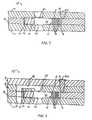
- FIG. 7shows a cross sectional view of a microvalve having a second inlet port with fluid entering from opposite sides of the microvalve to provide pressure balancing
- FIG. 8shows a cross sectional view of another microvalve having a second inlet port with fluid entering from the same side of the microvalve to provide pressure balancing
- FIGS. 9A , 9 B, 9 C and 10show partial top plan views illustrating displaceable members including extensions to provide fluid force compensation
- FIGS. 11-13show partial top plan views illustrating the microvalve of the present invention further including one or more baffles and extensions for redirecting fluid flow;
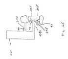
- FIG. 14shows a partial cross-sectional view of a microvalve having an angled inlet and outlet port
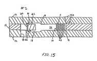
- FIG. 15shows a cross-sectional view of a proportional gas microvalve of the present invention
- FIGS. 16 a-fillustrate the fabrication process flow in accordance with the invention
- FIG. 17shows a top plan view of a displaceable member for closing and opening two inlet ports for control of fluid flow to outlet port;
- FIG. 18shows a schematic of a portion of an anti-lock brake system illustrating the utilization of valves
- FIG. 19shows a top plan view of a microvalve having two displaceable members for independently closing and opening two inlet ports for control of fluid flow to outlet port.
- the present inventioncomprises a semiconductor micromechanical device which includes a semiconductor layer defining a cavity.
- a displaceable structureis suspended within the cavity by first and second members which also are suspended within the cavity. At least one of the suspended members is operative as an actuator which can displace the displaceable structure within the cavity.
- the microvalve 10 of the first embodimentgenerally comprises three layers or substrates: first layer 12 , second layer 14 and third layer 16 .
- the first layer 12defines inlet port 20 and outlet port 22 .
- the second layer 14is secured between first layer 12 and third layer 16 , and defines a cavity 24 including a flow area to permit fluid flow between inlet port 20 and outlet port 22 .
- the second layer 14further defines a displaceable member 26 which can be displaced in response to thermal actuators 28 , 30 to open and close inlet port 20 .
- the displaceable member 26is elongated. Electrical contacts 32 a , 32 b , 34 a , 34 b for electrical thermal heating of actuators 28 , 30 , respectively, are provided in vias through the third or cap layer 16 .
- each of actuators 28 , 30exerts a force in a direction indicated by arrows D 28 and D 30 , respectively.
- Forces in directions D 28 and D 30cause displaceable member 26 to be displaced in a direction indicated by arrow D 26 such that at least a portion of displaceable member 26 becomes vertically aligned with inlet port 20 .
- the currenttherefore, serves as an input stimulus which actuates the actuators.
- the at least partial vertical alignment of displaceable member 26 relative to the inlet port 20at least partially closes the inlet port 20 .
- the amount of the displacement or alignment of displaceable member 26may be selected to control, for example, the rate of fluid flow.
- actuators 28 , 30exert forces in directions opposite to those indicated by arrows D 28 and D 30 , respectively, to return displaceable member 26 to its normally open position relative to the inlet port 20 by displacing displaceable member 26 in a direction opposite to that indicated by arrow D 26 .
- microvalve 10may be configured such that displaceable member 26 is in a normally closed position relative to the inlet port 20 and is displaceable to open inlet port 20 .
- microvalve 10may be configured such that displaceable member 26 is in a normally open or closed position relative to the outlet port 22 and is displaceable to close or open the outlet port 22 .
- each of first, second and third layers 12 , 14 , 16is made of silicon or other semiconductor materials.
- first and/or third layers 12 , 16may be made of glass (Pyrex), conductive ceramic, steel, aluminum, and/or any other metallic or conductive materials.
- the second layer 14is preferably a single-crystal semiconductor (SCS) as it is strong, flexible and more resistant to performance degradation.
- SCSsingle-crystal semiconductor
- microvalve 10is generally described herein as opening and closing inlet port 20 , such description is solely for illustrative purposes only and, clearly, microvalve 10 can be easily adapted to open or close outlet port 22 . Further, although microvalve 10 is described herein as a normally open (N.O.) valve, it can be easily adapted to be a normally closed (N.C.) valve. In addition, for purposes of clarity and brevity of the description herein, only actuator 28 and corresponding electrical contacts 32 a , 32 b will generally be described, although the description is correspondingly applicable to actuator 30 and electrical contacts 34 a , 34 b.
- First and third layers 12 , 16preferably define shallow recesses 18 , although only recess 18 in first layer 12 is shown in FIG. 1 .
- Recesses 18are defined in regions aligned with displaceable member 26 and actuators 28 , 30 of second layer 14 to provide clearance for suspension of displaceable member 26 and actuators 28 , 30 between first and third layers 12 , 16 and for displacement thereof within cavity 24 in the plane of the second layer 14 .
- Recesses 18may also be defined in regions aligned with cavity 24 to further facilitate fluid flow through cavity 24 .
- displaceable member 26 and actuators 28 , 30 of second layer 14may be indented, or thinned, (not shown) from first and third layers 12 , 16 to provide clearance therebetween.
- recesses 18 and/or the indents of displaceable member 26 and actuators 28 , 30may be of a uniform depth or varying depths.
- recess 18 and/or indentsmay provide a clearance of approximately 0.5 ⁇ m in the region near inlet 20 between displaceable member 26 and each of first and third layers 12 , 16 in order to minimize fluid leakage by reducing the distance between displaceable member 26 and inlet port 20 when displaceable member 26 is aligned over inlet port 20 to close off fluid flow.
- recess 18 and/or indentsmay provide a clearance of approximately 10-100 ⁇ m or less in other regions such as those between actuators 28 , 30 and each of first and third layers 12 , 16 to reduce the heat-loss rate and, thus, the power for continuous operation.
- recesses 18 of the first embodimentpreferably has a depth of approximately 0.5 ⁇ m.
- a gapis formed between a surface of recess 18 and stopper end portion 42 when displaceable member 26 is in a closed position. Liquid leakage through microvalve 10 , even with such a gap, is minimal. This small leakage has already been demonstrated by a larger 5 ⁇ m gap in a conventional solenoid fluid valve currently utilized for anti-lock brake systems.
- provision of recesses 18 approximately 0.5 ⁇ m in depth for a fluidic microvalveis preferred in certain applications.
- the second layer 14is preferably doped, more preferably highly doped, for example, a highly doped P-type single-crystal semiconductor (SCS). By doping, second layer 14 has a low resistivity. Low resistivity facilitates high current flow through thermal actuators 28 , 30 . Current may be applied through actuators 28 , 30 via contacts 32 a, b and 34 a, b , respectively. By increasing the current applied to contacts 32 a, b and 34 a, b , thermal expansion of actuators 28 , 30 increases resulting in an increase of the forces exerted by actuators 28 , 30 on the displaceable member 26 .
- SCSsingle-crystal semiconductor
- the resistivity ⁇ of second layer 14is preferably approximately 0.001-0.1 ⁇ cm such that a current flow from one side to the other side of ribs 48 results in a desirable amount of heating of and heat dissipation by the ribs.
- ribs 48are silicon
- ribs 48can withstand temperatures of up to 1100° C. and preferably up to approximately 500° C.
- silicon ribs 48are heated by between 10° C. and 500° C., and more preferably between 100° C. to 200° C.
- actuation of microvalve 10is dependent upon the heating of ribs 48 relative to the temperature of the remainder of the microvalve 10 and is independent of the ambient temperature.
- Electrical contacts 32 a-bare provided in third layer 16 and are vertically aligned with thermal actuator 28 . Electrical contacts 32 a-b provide electrical contact, through vias 35 , for the application of current to actuators 28 .
- the ribs 48serve as conductive paths through the highly doped second layer 14 between contacts 32 a and 32 b . Contacts 32 a-b are preferably in electrical contact with regions of second layer 14 that are isolated except for current conduction paths formed by ribs 48 . Such electrical isolation may be established by providing trenches 36 in the second layer 14 to prevent a short circuit between electrical contacts 32 a and 32 b . Trenches 36 may be filled with a dielectric material to planarize trenches 36 . In addition, electrical isolation from the fluid may be established by oxidizing the ribs 48 .
- first and second layers 12 , 14 and between second and third layers 14 , 16are achieved because the first and third layers 12 , 16 , unlike second layer 14 , have a low doping level and are only minimally electrically conductive, such that the applied current remains in second layer 14 .
- the layers 12 , 14 , 16comprise silicon
- the surface of the layers 12 , 14 , 16may also be oxidized to provide further electrical isolation.
- an opening 16 amay be formed through layer 16 and a pressure sensor 16 b placed in a fluid-tight manner in opening 16 a . This allows a measurement to be made of the pressure difference between the inlet 20 a and outlet 72 .
- pressure sensors 16 bare well known in the art.
- the electrical contacts 32 a , 32 bare vertically aligned with the ribs 48 of actuator 28 such that one of the contacts (e.g., 32 a ) is vertically aligned with the ribs on one side of the isolation trench 36 and the other of the contacts (e.g., 32 b ) is vertically aligned with the ribs on the other side of the trench 36 .
- the contacts 34 a , 34 bare similarly vertically aligned with the ribs 50 of the actuator 30 . It will be appreciated that such vertical alignment provides a more compact microvalve.
- the displaceable member 26has a first actuator end portion 40 in contact with thermal actuators 28 , 30 and a second stopper end portion 42 disposed and shaped for opening and closing inlet port 20 .
- the displaceable member 26can, but does not necessarily, increase in cross-sectional area from the first actuator end portion 40 to stopper end portion 42 .
- each of actuators 28 , 30comprises a shaft 44 , 46 with ribs 48 , 50 extending therefrom, respectively, wherein shafts 44 , 46 are generally perpendicular to the displaceable member 26 .
- shafts 44 , 46are generally perpendicular to the displaceable member 26 .
- applying a current through ribs 48causes them to thermally expand which in turn causes shaft 44 to exert a force on the displaceable member 26 in a direction as indicated by arrow D 28 .
- the shaft 44 , 46 and ribs 48 , 50constitute a unitary structure that serves both to suspend the displaceable member 26 within the cavity 24 and to impart displacement force to the displaceable member 26 .
- thermal actuators 28 , 30are disposed in cavity 24 to be filled with fluid
- thermal actuators 28 , 30are preferably disposed outside of the area of fluid flow between inlet and outlet ports 20 , 22 .
- the fluid in the area outside of the fluid flow areawould generally be stagnant and, essentially, a vacuum would be needed to remove this dead volume of fluid.
- the dead volume of fluidmay also act as a thermal insulator between thermal actuators 28 , 30 and the fluid flow to prevent the fluid flow from being heated thereby.
- Actuators 28 , 30 and displaceable member 26are suspended within the cavity 24 between first and third layers 12 , 16 .
- ribs 48are anchored or fixed at one end to second layer 14 such that ribs 48 are suspended by second layer 14 between first and third layers 12 , 16 .
- Shaft 44 and displaceable member 26are in turn similarly suspended, the shaft 44 being supported by ribs 48 and the displaceable member 26 being supported by shafts 44 , 46 .
- thermal actuators 28 , 30have high aspect ratios (the ratio of height to width) formed by deep reaction ion etching (DRIE).
- DRIEdeep reaction ion etching
- Thermal actuators 28 , 30preferably have aspect ratios in the range of 1:1 to 50:1, and more preferably approximately 20:1.
- the displaceable member 26preferably has an aspect ratio in the range of 0.5:1 to 50:1, and more preferably approximately 1:1.
- each of suspended ribs 48 , shaft 44 and displaceable member 26is displaceable in the plane of second layer 14 while limited in the direction of displacement by the respective support structure.
- Actuator 28is shown in more detail in FIG. 3 . Because ribs 48 are anchored at one end to second layer 14 , ribs 48 cannot thermally expand toward the anchored end. Rather, ribs 48 can thermally expand toward shaft 44 . Each end of rib 48 is preferably tapered to achieve a smaller cross-section at the junctions between rib 48 and second layer 14 and/or between rib 48 and shaft 44 . The tapered junctions allow hinging action and thus allow displacement of shaft 44 . In addition, ribs 48 are at an angle ⁇ relative to the perpendicular of shaft 44 such that upon thermal expansion of ribs 48 , ribs 48 displace shaft 44 toward first actuator end portion 40 of displaceable member 26 .
- Rib angle ⁇for purposes of amplifying the displacement of shaft 44 , is preferably relatively small, for example, between 1 and 5°. However, it is considered that rib angle ⁇ extend to 30° or more. A small angle ⁇ maximizes the displacement of shaft 44 toward actuator end portion 40 of displaceable member 26 for a given amount of thermal expansion of each rib 48 .
- actuator 28may have five pairs of ribs 48 as shown in FIGS. 1 and 2 .
- the number of rib pairsmay be easily varied to achieve the desired force exerted on stopper end portion 42 of displaceable member 26 .
- ribs 48are provided in pairs, one opposite the other relative to shaft 44 , such that forces perpendicular to shaft 44 exerted by ribs 48 are canceled out by opposing ribs 48 .
- the net force exerted by ribs 48is parallel to shaft 44 and shaft 44 in turn exerts the forces on actuator end portion 40 of displaceable member 26 .
- each rib 48is approximately 200-4000 ⁇ m in length, 50-200 ⁇ m in width and 400 ⁇ m in height and thus with an aspect ratio of approximately 2:1 to 8:1.
- Shaft 44is preferably 0.5 to 2 mm in length and with an aspect ratio of approximately 5:1 to 10:1.
- displaceable member 26is preferably approximately 2-6 mm in length, 250-1000 ⁇ m in width and 400 ⁇ m in height.
- This forcetranslates to approximately 0.1 N of force and 150-200 ⁇ m of displacement at stopper end portion 42 of displaceable member 26 .
- a displacement of approximately 400 ⁇ m at stopper end portion 42 of displaceable member 26can be easily achieved with microvalve 10 of similar dimensions.
- Such a microvalvecan have a switching time of less than 10 ms, can withstand up to approximately 5 kpsi of fluid pressure with pressure balancing of displaceable member 26 as will be discussed and can accommodate over 0.5 liters per minute of fluid flow.
- Shafts 44 , 46 of thermal actuators 28 , 30are disposed relative to displaceable member 26 to exert displacement torque force on actuator end portion 40 upon displacement of shafts 44 , 46 toward actuator end portion 40 .
- the displaced forceessentially is a torque force about a locus of member 26 between the first and second shafts 44 , 46 as illustrated by arrow D 26 .
- actuators 28 , 30are preferably disposed on opposing sides of displaceable member 26 and offset relative to each other along the axial length of displaceable member 26 . The offset distance may be selected according to the desired torque force at and displacement of stopper end portion 42 of displaceable member 26 .
- the displacement of shaft 44is generally inversely proportional to the force exerted by shaft 44 .
- a larger offset distancewould result in a greater displacement force at and a smaller displacement of stopper end portion 42 .
- a smaller offset distancewould result in a smaller torque force at and a greater displacement of stopper end portion 42 .
- the distance by which thermal actuators 28 , 30 are offset from each other along the axial length of displaceable member 26may be selected to achieve the desired balance between torque and displacement.
- thermal actuator 28To actuate thermal actuator 28 , a current is applied between electrical contacts 32 a , 32 b to heat ribs 48 , causing ribs 48 to thermally expand. Thermal expansion of ribs 48 operates to displace shaft 44 toward the first actuator end portion 40 of displaceable member 26 . Similarly, a current is simultaneously applied between electrical contacts 34 a , 34 b to heat ribs 50 , causing ribs 50 to thermally expand. Thermal expansion of ribs 50 also displaces shaft 46 toward actuator end portion 40 of displaceable member 26 .
- displaceable member 26is displaced in the plane of second layer 14 at a locus of displaceable member 26 approximately midway between shafts 44 , 46 . Displacement of displaceable member 26 causes the second stopper end portion 42 to be displaced relative to inlet port 20 to open or close inlet port 20 .
- the amount of the applied currentcan be controlled to control the level of fluid flow through microvalve 10 .
- Controlling the applied current, and thus the powercontrols the extent of thermal expansion of ribs 48 , 50 , the displacement of shafts 44 , 46 , the rotation of displaceable member 26 , and thus the displacement of the second stopper end portion 42 relative to inlet port 20 .
- the proportional extent to which stopper end portion 42 of displaceable member 26 opens and closes flow through inlet port 20 and the resultant fluid flow through microvalve 10can be precisely controlled by controlling the amount of the applied current.
- the current applied to the microvalvecan be pulsed to open and close the port. With pulse-width modulated input signals timed for the same average power delivery and thus the same heating, the desired overall fluid flow rate can thereby be achieved.
- inlet port 20may be similar to the shape of stopper end portion 42 of displaceable member 26 , as shown in FIG. 1 . Such a shape maximizes the area of inlet port 20 exposed by a given displacement of stopper end portion 42 of displaceable member 26 , i.e. minimizes the displacement of stopper end portion 42 of displaceable member 26 to expose a given area of inlet port 20 .
- Outlet port 22may be of any suitable shape and is preferably of a maximal size given the configuration of the microvalve 10 so as to minimize the pressure drop across outlet port 22 . Of course, any other suitable shape and sizes of inlet port 20 and outlet port 22 may be utilized and inlet port 20 and outlet port 22 may be of different shapes.
- the actuatorAfter current is no longer applied to electrical contacts 32 a , 32 b , the actuator is allowed to passively cool and return displaceable member 26 to its open position. Alternatively, where two or more actuators are used, one actuator may be used to open and the other actuator may be used to close the microvalve 10 as in the configuration of FIG. 5 B. It is desirable to provide a heat sink (not shown), comprising any thermally conductive metal or ceramic, such as aluminum, for example, attached to the bottom surface of the first layer 12 .
- FIG. 4shows a top plan view of alternative actuators 102 , 104 and displaceable member 26 .
- Each of actuators 102 , 104comprises two or more bars 106 connected to shafts 108 , 110 .
- Shafts 108 , 110similar to shafts 44 , 46 of actuators 28 , 30 , are disposed on opposing sides of displaceable member 26 and offset from each other in order to exert a torque force on displaceable member 26 .
- each of shafts 108 , 110would be equal to the thermal expansion of bars 106 as there is no displacement amplification. Additional bars 106 may be provided to increase the force exerted by shafts 108 , 110 upon displaceable member 26 .
- two displaceable members 112 , 114are disposed at an angle relative to each of actuators 26 , 28 for displacing stopper 116 in directions as indicated by arrow 118 .
- the angle of displaceable members 112 , 114 relative to shafts 44 , 46 , respectively,can be selected to amplify displacement of stopper 116 . Increasing the displacement of stopper 116 would, however, decrease the force at stopper 116 , as the relationship between displacement and force would of course also apply here.
- actuators 118 , 120may be disposed on the same side of displaceable member 26 .
- displaceable member 26may be displaced to open inlet port 20 by actuating only actuator 118 .
- Employing only one actuatorresults in one half of the force and one half of the displacement of displaceable member 26 .
- this configurationhas the advantage that displaceable member 26 may be displaced to close inlet port 20 by actuating actuator 120 , before actuator 118 has passively cooled and returned to its initial position. This is in contrast to configurations having actuators on opposite sides of the displaceable member which rely upon the passive cooling of the actuators to displace the displaceable member back to the closed position.
- FIGS. 6A-6Eshow examples of other variations of actuator(s).
- the displaceable member 26 Amay be suspended by elements 29 A, 31 A. Either or both of the elements 29 A and 31 A may serve as expansible actuator.
- actuator element 29 Aexpands toward the displaceable member 26 A upon actuation, the actuator element 29 A displaces the member 26 A about the anchor element 31 A.
- both elements 29 A, 31 Aserve as expansible actuators
- actuation of both elements 29 A, 31 Adisplaces the member 26 A about a pivot point along the displaceable member approximately midpoint relative to the elements 29 A, 31 A, depending upon the relative amount of expansions of the actuator elements.
- elements 29 A, 31 Aserve as actuators, either element may be actuated without the actuation of the other.
- elements 29 A, 31 Adefine tapers 33 A, 37 A, respectively to facilitate displacement of the displaceable member 26 A.
- the displaceable member 26 Bmay be suspended by element 29 B and by the distal end portion 31 B of the displaceable member.
- element 29 Bserves as an expansible actuator such that upon action, it expands toward the displaceable member 26 B, displacing the member 26 A about the distal end portion 31 B.
- distal end portion 31 Bmay also serve as an expansible actuator.
- element 29 Bdefines a taper 33 B to facilitate displacement of the displaceable member 26 A relative to element 29 B.
- displaceable member 26 Bpreferably also defines a taper 37 B at the distal end portion 31 B such that the cross-sectional area of displaceable member 26 B generally decreases toward the distal end portion 31 B.
- the displaceable member 26 Cmay be suspended by a single actuator 29 C, comprising extension arms 39 and 41 .
- Extension arms 39 and 41have different cross-sectional areas such that, for example, the cross-sectional area of extension arm 39 is less than that of extension arm 41 .
- the extension arm 39has a higher resistance and thus greater thermal expansion upon actuation than those of extension arm 41 .
- the displaceable member 26 Cis displaced further by extension arm 39 than by extension arm 41 such that the member 26 C is linearly displaced in direction D 43 and rotated about a pivot at approximately the intersection of the expanded extension arm 41 and the displaceable member 26 C.
- extension arms 39 , 41may provide a taper to facilitate displacement of the displaceable member 26 C.
- extension arms 39 , 41 as well as displaceable member 26 Care doped to allow the application and flow of current therethrough.
- the displaceable member 26 Dmay be suspended by two actuators 29 D and 31 D, disposed on either side of member 26 D.
- Actuator 29 Dcomprises extension arms 39 ′ and 41 ′ having different cross-sectional areas such that the cross-sectional area of extension arm 39 ′ is less than that of extension arm 41 ′.
- actuator 31 Dcomprises extension arms 39 ′′ and 41 ′′ having different cross-sectional areas such that the cross-sectional area of extension arm 39 ′′ is less than that of extension arm 41 ′′.
- Extension arms 39 and 39 ′ and/or extension arms 41 and 41 ′may or may not have the same cross-sectional area. As described above, because of the difference in the cross-sectional areas, extension arms 39 ′, 39 ′′ has higher resistances and thus greater thermal expansions upon actuation than those of extension arms 41 ′, 41 ′′, respectively.
- actuators 29 D and 31 Dare preferably disposed such that extension arm 41 ′ is closer to extension arm 41 ′′ than to extension arm 39 ′′ and extension arm 41 ′′ is closer to extension arm 41 ′ than to extension arm 39 ′.
- the displaceable member 26 Dis displaced further by extension arms 39 ′, 39 ′′ than by extension arms 41 ′, 41 ′′, respectively, such that the member 26 D is rotated about a pivot at approximately the midpoint between actuators 29 D and 31 D.
- any or all of extension arms 39 ′, 39 ′′, 41 ′, 41 ′′may provide a taper to facilitate displacement of the displaceable member 26 C.
- extension arms 39 ′, 39 ′′, 41 ′, 41 ′′ as well as displaceable member 26 Dare doped to allow the application and flow of current therethrough.
- FIG. 6 EYet another embodiment of the present invention is shown in FIG. 6 E.
- a displaceable member 26 Eis supported by a fixed, anchor element 35 E and an actuator 29 E.
- Actuator 29 Eincludes a shaft 44 E interconnected with two ribs 48 E which are extendible in a direction parallel to the rib in response to an electric signal.
- Ribs 48 Epreferable extend from opposite sides of shaft 44 E and at an angle thereto such that extension of ribs 48 E causes shaft 44 E to displace in a direction towards member 26 E.
- extension arms 48 Emay provide a taper to facilitate displacement of the displaceable member 26 E. Similar to the variation shown in FIG. 6C , extension arms 48 E are preferably doped to allow the application and flow of current therethrough.
- one or more sensors 47may, though need not, be integrally secured to the actuator to detect motion thereof.
- the sensorcan be a device such as a piezoresistor, which changes its resistance upon the occurrence of changes in stress within a portion of the actuator, as when, for example, it bends, expands or contracts during activation and/or deactivation.
- the sensor 47may be placed on a side surface of a rib or on anchor element 35 E. The change in the piezoresistor's resistance may be utilized to sense the displacement or movement of the displaceable member.
- microvalve 10 of the present inventionmay be easily adapted and employed in microvalve 10 of the present invention to achieve a displacement of second stopper end portion 42 .
- one of the two actuators of the microvalve of FIG. 1may be replaced by a single beam for anchoring and/or pivoting the displaceable member.
- the displaceable memberthus may be rotated about a center of rotation or a pivot located along the displaceable member approximately halfway between the fixed beam and the shaft of the actuator.
- the displaceable memberwould be displaceable between an open and a closed position by thermal actuation of the only actuator.
- FIG. 7there is shown a cross-sectional view of an alternative embodiment in which the third layer 16 of microvalve 10 ′ defines a second inlet port 52 disposed opposite inlet port 20 for fluid pressure balancing.
- Inlet port 20 and second inlet port 52thus introduce fluid into cavity 24 such that the fluid impinges on opposite faces of stopper end portion 42 when displaceable member 26 is in the closed position or between the open and closed positions. This at least partially compensates or balances the fluid pressure exerted on the displaceable member resulting from fluid entering cavity 24 .
- the fluid pressure exerted on stopper end portion 42occurs when microvalve 10 ′ is in the closed position or between the open and closed positions such that stopper end portion 42 is partially disposed in a region vertically aligned with inlet port 20 .
- fluidflows through inlet port 20 , fluid impinges upon and exerts pressure on a surface of stopper end portion 42 adjacent first layer 12 and enters into cavity 24 .
- displaceable member 26 of a presently preferred embodimentcan withstand approximately 100 psi of fluid pressure when displaceable member 26 is made of silicon, it can still be desirable to compensate for the fluid pressure exerted on stopper end portion 42 of displaceable member 26 . Complete compensation in unnecessary, though, as the inherent strength of the material, such as silicon, can easily withstand a relatively small imbalance of pressure.
- microvalve 10can withstand fluid pressures up to thousands of psi.
- FIG. 8illustrates a cross-sectional view of another alternative embodiment which includes an inlet channel 56 and a second inlet port 52 ′ to compensate or balance the vertical fluid impingement forces on the displaceable member 26 .
- Inlet channel 56extends through first, second and third layers 12 , 14 , 16 and directs the flow into cavity 24 through second inlet port 52 .
- fluidmay be introduced through first layer 12 of microvalve 10 ′′ and directed to be introduced into cavity 24 from opposite directions.
- Fourth layer 54is provided to cap inlet passageway 56 over third layer 16 and is disposed such that third layer is between second and fourth layers 14 , 54 .
- stopper end portion 42 of the displaceable member 26is also subjected to a localized fluid force on inlet fluid flow face 58 as well as flow perturbations.
- the localized force on face 58is caused by a bend in the flow path as fluid enters cavity 24 through inlet port 20 and/or second inlet port 52 .
- This forceurges displaceable member 26 to be displaced in the direction determined by the orientation of the fluid force.
- itis also desirable to compensate for the flow perturbations in the same plane as the displaceable member motion.
- FIGS. 9-13illustrate various methods and configurations to achieve the compensation of fluid forces.
- Each of the embodiments shown in FIGS. 9-13includes a fluid force coupling surface that is impinged by fluid flowing from the inlet port 20 to the outlet port 22 to subject the displaceable member 26 to a coupling force that is exerted by the fluid.
- the coupling forceis caused either by the impingement of the fluid flow on a surface different from the face 58 (embodiments shown in FIGS. 9 and 10 ) or by redirecting or at least perturbing the fluid flow back toward the face 58 (embodiments shown in FIGS. 11 - 13 ).
- displaceable member 26 amay further comprise a generally U-shaped extension 60 to form a P-shaped displaceable member 26 a wherein the U-shaped extension 60 at least partially encircles or encloses outlet port 22 .
- Fluid flowwould exert a force on U-shaped extension 60 to at least partially compensate and balance the localized force at face 58 of stopper end portion 42 .
- U-shaped extension 60additionally encloses fluid flow between stopper end portion 42 of displaceable member and extension 60 and thus may also reduce the fluid leakage of the microvalve.
- the end usefurther allows the pressure exterior to the enclosure to be relatively constant resulting in little or no net pressure from areas exterior to the enclosure.
- Other suitable shapes of extension 60may be utilized, such as L-shaped to form an h-shaped displaceable member (not shown).
- displaceable member 26 ccould include a smaller generally U-shaped extension 60 c to form a P-shaped displaceable member 26 c .
- Extension 60 cis sized such that inlet port 20 will be open to the interior U-shaped extension 60 c when the microvalve is in a closed position.
- fluidpreferably flows both from the top and the bottom of displaceable member 60 c . This achieves pressure balancing in two directions: at the top and bottom faces; and at the left and right faces.
- FIG. 9 cshows yet another embodiment of a displaceable member 26 d having a taper 61 d at stopper end portion 42 d .
- the width of displaceable member 26 dis smaller at stopper end portion 42 d thereof than at the opposite end.
- the end of stopper end portion 42 d of displaceable member 26 dmay move a greater distance upon actuation of displaceable member 26 d than any other portion thereof.
- displaceable member 26 bmay comprise extension 62 disposed between inlet 20 and outlet 22 rather than encircle outlet 22 .
- Extension 62redirects fluid flow such that fluid flow exerts a force on extension 62 to at least partially compensate and balance the localized decrease force at face 58 of stopper end portion 42 .
- one or more members fixed to first layer 12 and/or third layer 16may alternatively or additionally be provided in cavity 24 to redirect fluid flow to compensate or balance the localized force on face 58 of stopper end portion 42 .
- member 64may be provided within cavity 24 and displaceable member 26 a may comprise extension 60 to enclose the fluid flow therein. The combination of extension 60 and member 64 may result in force compensation without redirecting the fluid flow at displaceable member 26 a .
- baffle 66may comprise a curved surface, as shown in FIG. 12 , to redirect flow toward face 58 , thereby compensating for the force.
- FIG. 13shows a microvalve having curves baffle 68 and baffles 70 which also redirect flow around baffles 70 to compensate and balance the fluid forces.
- FIG. 14is an illustrative drawing of yet another alternative embodiment of the invention in which an angled outlet 72 and an angled inlet 20 a serve as fluid force flow compensation members.
- angled outlet 72 and angled inlet 20 aare shown in FIG. 14 as being partly defined by another layer 73 , they may be defined only by first layer 12 .
- Fluidflows into cavity 24 through angled inlet 20 a in a direction indicated by arrow 74 at inlet angle ⁇ and fluid exits from cavity 24 in a direction indicated by arrow 76 at exit angle ⁇ .
- Inlet angle ⁇is controlled by displacement of stopper end portion 42 of displaceable member 26 while exit angle ⁇ is generally a constant. Fluid inlet and exit angles ⁇ , ⁇ , are selected to balance flow forces.
- an opening 16 amay be formed through layer 16 and a pressure sensor 16 b placed in a fluid-tight manner in opening 16 a . This allows a measurement to be made of the pressure difference between the inlet 20 a and outlet 72 .
- pressure sensors 16 bare well known in the art.
- Microvalve 78may be utilized as a gas valve.
- the gap between recess 18 and stopper end portion 42 when displaceable member 26 is in a closed positionis preferably less than the 0.5 ⁇ m gap for the fluidic microvalve 10 . Minimizing the gap prevents or minimizes gas leakage as leakage is not reduced by high viscosity as is the case for a liquid valve. The size of the gap may be reduced by reducing the depth of recesses 18 in first layer 12 and/or third layer 16 .
- the size the of gapmay be further reduced by providing flanges 80 at an inlet face of stopper end portion 42 of displaceable member 26 .
- Flanges 80enhance the seal between inlet face of stopper end portion 42 and inlet 20 b when displaceable member 26 is in a closed position.
- an inlet channel 79is provided through first and second layers 12 , 14 to direct gas flow through inlet port 20 b into cavity 24 such that gas enters cavity 24 in a direction parallel to the plane of the second layer 14 .
- the inlet port 20 bis preferably defined along a sidewall of the cavity 24 that is generally perpendicular to the plane of the second layer 14 .
- Fabrication of a microvalve of a present embodiment of the inventioninvolves fusion bonding, such as silicon fusion bonding, and deep reactive ion etching (DRIE). Fusion bonding allows the bonding of one silicon layer to another to form one single mechanical structure. The fusion bond has been demonstrated to be at the molecular level and provides very high mechanical robustness. Fusion bonding techniques are well known. See, for example, K. E. Petersen, D. Gee, F. Pourahmadi, R. Craddock, J. Brown and L. Christel, “Surface Micromachined Structures Fabricated with Silicon Fusion Bonding,” Proceedings, Transducers 91, June 1992, pp. 397-399, which is expressly incorporated herein by reference.
- the process for fabricating a silicon microstructure in accordance with a presently preferred embodiment of the inventionis explained with reference to FIGS. 16 a-f .
- the current embodimentemploys three silicon wafers. Using three silicon wafers, the process results in the formation of a prescribed single-crystal silicon structure (SCS) microstructure as an integral portion of the second wafer, corresponding to second layer 14 .
- SCSsingle-crystal silicon structure
- First and third wafers, corresponding to the first and second layers 12 , 16serve as carriers for the second wafer.
- the carrierscan be formed of glass (Pyrex), for example.
- the first waferis patterned with a photoresist to define recessed region(s) to be formed therein and the recessed region(s) are formed using standard semiconductor techniques such as, for example, plasma etching, wet-etching with KOH or other silicon etchants, or differential oxide growth.
- the recessed region(s)can have any arbitrary geometry and can have any required depth, from less than 0.1 ⁇ m to more than 100 ⁇ m, for example. In the current embodiment, the recessed regions has a depth of approximately 1 ⁇ m.
- the recessed regionneed not have a single, uniform depth.
- several standard silicon etch stepsmay be employed to produce several different depths that can be used for different mechanical functions.
- second layermay be indented (not shown) from first and third layers 12 , 16 to provide clearance therebetween, as described above.
- each of the first and third wafer surfacescan be either bare silicon or it can be coated with an oxide layer.
- the base of the recessed regioncan be either bare silicon, oxidized silicon, doped silicon, or it can be coated with any other thin film capable of withstanding subsequent wafer bonding and processing temperatures.
- an inlet portis then etched through the first wafer.
- the outlet portmay be simultaneously etched through the first wafer. Alternatively or additionally, the outlet port may be etched through the third wafer.
- the patterned surface of the first waferis bonded to a second wafer, preferably doped, by silicon fusion bonding (or direct bonding) process.
- silicon fusion bondingor direct bonding
- fusion bonding techniquesare well known.
- the first and second wafersare made hydrophilic. That is, they are treated with an agent such as hot ammonium hydroxide or a hot sulfuric acid and hydrogen peroxide solution or another strong oxidant, that hydrates the surfaces. After drying, the two wafers then are placed in an oxidizing atmosphere at a temperature of 400° C.-1200° C. for approximately one hour.
- the silicon fusion bonding technique described abovebonds the first and second wafers together without the use of an intermediate adhesive material that could have a different coefficient of thermal expansion than the single-crystal silicon wafers. Furthermore, fusion bonding can be performed in which oxide or nitride layers have been formed in the bonded surfaces of one or both of the wafers.
- the first and second waferscan be adhered together with an adhesive such as a photoresist.
- the first and second waferscan have their major surfaces coated with a metal layer, such as gold, used to alloy the wafers to one another.
- a glass (Pyrex 7740) carrieris used instead of the first silicon wafers, the second wafer can be anodically bonded to such glass carrier.
- the second wafermay be thinned and polished to the thickness required by the particular application.
- electrochemical etchingECE
- Diffused heatersmay be incorporated into a plane surface of second layer 14 by diffusion.
- any necessary circuits or other thin film depositions and patterningcan be performed using standard silicon processing techniques.
- DRIEDeep Reactive Ion Etching
- Reactive Ion etch equipmentnow allows the etching of holes or trenches which are very deep (>100 microns), while maintaining high aspect ratios (the ratio between the depth of the etched region and the width of the etched region). It has been found that this equipment is capable of at least 30:1 aspect ratios for trenches as deep as 300 microns.
- DRIEin essence, involves a synergistic action between chemical etch and ion bombardment.
- the DRIE processadvantageously etches in the vertical direction at a much higher rate than in the lateral direction (i.e., anisotropically) regardless of silicon crystal planes or crystal orientation.
- relatively deep substantially vertical trenches or slotscan be formed in the single-crystal silicon (SCS) second wafer.
- SCSsingle-crystal silicon
- a DRIE processis used to etch completely through the second wafer to define the displaceable member and the actuator(s).
- the DRIE etching stepmechanically releases the single-crystal silicon (SCS) microstructures formed in the second wafer, which are then free to move relative to and in the plane of the second wafer.
- SCSsingle-crystal silicon
- An inductively coupled plasma sourceetches the silicon using photoresist or silicon dioxide as a mask. Polymerization of a source gas on the sidewalls of the etched trenches slows the lateral etch rate and allows high anisotropy.
- the etching chemicalis SF 6 at, for example, 15 millitorr.
- a six-micron thick photoresist layerserves as the patterning mask.
- the photoresist selectivityis approximately 50:1, which makes it possible to etch to depths of 300 ⁇ m with about 6 ⁇ m of resist.
- the “multiplex RIE system”, available from Surface Technology Systems (STS)which has a place of business in Redwood City, Calif. can be employed to perform inductively coupled plasma DRIE, or from Unaxis in St. Moscow, Fla.
- fusion bonding and DRIEallows the construction of three-dimensional structures, such as the microvalve of the present invention. See, for example, E. H. Klaassen, K. Petersen, J. M. Noworolski, J. Logan, N. I. Maluf, J. Brown, C. Storment, W. McCulley and G. T. A. Kovacs, “Silicon Fusion Bonding and Deep Reactive Ion Etching; A New Technology for Microstructures”, Proceedings, Transducers 95, Sweden, 1995, at pp. 556-559.
- the patterned surface of the third waferis bonded to the second wafer by silicon fusion bonding (or direct bonding) process, as described above with reference to FIG. 16 c .
- silicon fusion bondingor direct bonding
- the third waferwas processed similar to the first wafer to define recessed region(s), inlet port and/or outlet port, as well as through-wafer contact hole(s) or via(s).
- a layer of electrically conductive material such as aluminumis deposited, such as by sputtering, onto the surfaces of the contact hole(s) or via(s), the surface of the second wafer exposed through the contact hole, and at least a portion of the exterior planar surface of the third wafer.
- the conductive layerthus forms bond pad(s) to enable electrical contact to the actuator(s). Any necessary circuits or other thin film depositions and patterning can be performed using standard silicon processing techniques on the third wafer.
- first and/or third layers 12 , 16can be made of glass (Pyrex) instead of silicon.
- the microvalvemay be formed from more than three wafers or layers or a micromechanical device may be formed from two or more wafer or layers.
- shallow cavitiescan be defined in the second layer 14 instead of in or in addition to the first and third layers 12 , 16 .
- each of the layersmay be separately processed and then assembled by an aligned bonding step.
- one of ordinary skill in the artcan easily make these and numerous other variations to the fabrication process by, for example, merely modifying the layout.
- microvalve of the present inventionmay be adapted for use in anti-lock brake systems, as described below, ink jet printing, refrigeration, pilots for larger valves, e.g., for automatic transmissions and large industrial valves.
- microvalve 82may also be adapted to selectively control two inlet ports 84 , 86 for fluid flow into one outlet 22 .
- the opening and closing of inlet ports 84 , 86are interdependent.
- Other details of microvalve 82will be understood from the above description with reference to other FIGS. Specifically, upon actuation, microvalve 82 may be controlled to open inlet port 84 while keeping inlet port 86 closed, or vice versa. Microvalve 82 may also be controlled to partially open both inlet ports 84 , 86 . Thus, microvalve 82 may be utilized to select fluid flow from one or two fluid sources.
- a single integrated microvalve 87 of the present inventionmay be utilized to replace a normally open (N.O.) and a normally closed (N.C.) solenoid valve utilized for each wheel of a conventional anti-lock brake system.
- N.O.normally open
- N.C.normally closed solenoid valve
- anti-lock brake system 100generally comprises a wheel speed sensor (not shown) for sensing the speed of wheel 102 , a normally open (N.O.) valve 86 and a normally closed (N.C.) valve 84 for controlling the flow of brake fluid to and from the brake caliper 104 of wheel 102 , an electronic control unit (ECU) 106 which receives input from the wheel speed sensor and outputs signals to microvalve 87 , a master cylinder 108 and a pump 110 .
- microvalve 87defines one outlet port 22 for directing brake fluid to the brake caliper and two displaceable members 88 , 90 to selectively open and close two inlet valves 84 , 86 , respectively.
- normally open inlet 86allows brake fluid to flow from master cylinder 108 to brake caliper 104 when the driver applies pressure to brake pedal 112 .
- normally closed valve 84is at least substantially closed to flow of brake fluid and normally open valve 86 allows for the flow of brake fluid to brake caliper 104 upon application of pressure on the brake pedal 112 by the driver.
- a slippery road surfacemay result in insufficient frictional or gripping force between the tire and the road such that, as the driver applies pressure to brake pedal 112 , brake caliper 104 locks wheel 102 .
- brake caliper 104locks wheel 102 and stops wheel 102 from rotating, wheel 102 skids along the slippery road so that the vehicle braking distance is increased.
- the vehiclecontinues to move due to the momentum of the vehicle.
- locking of the wheels by the brake systemoccurs when the gripping force between the tire and the road is less than the braking or gripping force between the wheel and the brake pads.
- the anti-lock brake systemalleviates or solves the wheel locking problem by regulating the brake-fluid pressure applied until the suitable level of brake force is reached, i.e. by decreasing the braking force to a level equal to the gripping force between the wheel and the road.
- the anti-lock brake systemis activated in response to the wheel speed sensor detecting that the wheels are tending toward locking.
- the electronic control unit (ECU) 106closes the N.O. valve. If the wheel speed sensor continues to sense the wheel tending toward locking even after the N.O. valve is closed, the ECU opens the N.C. valve and pumps some brake fluid from the wheel cylinder or caliper into the master cylinder.
- valveis repeatedly pulsed open and closed to regulate flow of the brake fluid until the computer determines that the braking is in control, i.e. when the wheel speed sensor detects that the wheels are no longer tending toward locking.
- N.C. valve open and closedproportionality of fluid flow control is achieved.
- the anti-lock brake systemis only activated while the brake pedal is depressed.
- a conventional anti-lock brake system of an automobile or passenger carutilizes two solenoid valves per wheel to control the flow of the brake fluid, resulting in the use of eight solenoid valves for a typical four-wheel passenger vehicle.
- solenoid valveshas several disadvantages, as discussed above.
- proportional solenoid valvesare available, cost-effective solenoid valves used for anti-lock brake systems perform solely on and off (binary) switching, thus requiring that the valves be pulsed to obtain the precise desired level of flow control. Such pulsing, being load, can be sensed by the driver while depressing the brake pedal which may be undesirable.
- Microvalve 87 as shown in FIG. 19can be utilized to replace the two solenoid valves of the conventional anti-lock brake system.
- Each of displaceable members 88 , 90is separately controlled by their respective thermal actuators.
- displaceable members 88 , 90would not both be in the open position simultaneously.
- displaceable member 90in the normally open position relative to inlet 86
- displaceable member 88in the normally closed position relative to inlet 84
- pump 110pumps brake fluid from master cylinder 108 to brake caliper 104 through normally open inlet 86 .
- the ECU 106When the ECU 106 senses that wheel 102 has exceeded predetermined thresholds, the ECU 106 sends a signal to microvalve 87 to displace displaceable member 90 to the closed position relative to inlet 86 and to displace displaceable member 88 from its closed position to a position between the open and closed positions relative to inlet 84 .
- Displacing displaceable member 88 to a position between the open and closed positions relative to inlet 84allows a desired level of brake fluid to be removed by the pump 110 from brake caliper 104 into master cylinder 108 .
- only one integrated microvalveis utilized to replace the two conventional binary solenoid valves.
- Displaceable member 88would preferably not be pulsed between the open and closed positions and is preferably displaced to a location between the open and the closed position to precisely control the desired amount of brake fluid to be pumped from the brake caliper 104 . However, it is to be appreciated that displaceable member 88 may be pulsed between the open and closed position relative to inlet 84 in order to achieve the proportional fluid flow control.
Landscapes
- Engineering & Computer Science (AREA)
- General Engineering & Computer Science (AREA)
- Chemical & Material Sciences (AREA)
- Mechanical Engineering (AREA)
- Dispersion Chemistry (AREA)
- Microelectronics & Electronic Packaging (AREA)
- Computer Hardware Design (AREA)
- Theoretical Computer Science (AREA)
- Physics & Mathematics (AREA)
- Fluid Mechanics (AREA)
- Analytical Chemistry (AREA)
- Micromachines (AREA)
- Temperature-Responsive Valves (AREA)
Abstract
Description
Claims (66)
Priority Applications (5)
| Application Number | Priority Date | Filing Date | Title |
|---|---|---|---|
| US10/024,957US7011378B2 (en) | 1998-09-03 | 2001-12-18 | Proportional micromechanical valve |
| EP02797418AEP1463899A4 (en) | 2001-12-18 | 2002-12-18 | Proportional micromechanical valve |
| PCT/US2002/040595WO2003052081A2 (en) | 2001-12-18 | 2002-12-18 | Proportional micromechanical valve |
| AU2002361782AAU2002361782A1 (en) | 2001-12-18 | 2002-12-18 | Proportional micromechanical valve |
| US11/075,057US7367359B2 (en) | 1998-09-03 | 2005-03-07 | Proportional micromechanical valve |
Applications Claiming Priority (2)
| Application Number | Priority Date | Filing Date | Title |
|---|---|---|---|
| US14802698A | 1998-09-03 | 1998-09-03 | |
| US10/024,957US7011378B2 (en) | 1998-09-03 | 2001-12-18 | Proportional micromechanical valve |
Related Parent Applications (1)
| Application Number | Title | Priority Date | Filing Date |
|---|---|---|---|
| US14802698AContinuation-In-Part | 1998-09-03 | 1998-09-03 |
Related Child Applications (1)
| Application Number | Title | Priority Date | Filing Date |
|---|---|---|---|
| US11/075,057ContinuationUS7367359B2 (en) | 1998-09-03 | 2005-03-07 | Proportional micromechanical valve |
Publications (2)
| Publication Number | Publication Date |
|---|---|
| US20020174891A1 US20020174891A1 (en) | 2002-11-28 |
| US7011378B2true US7011378B2 (en) | 2006-03-14 |
Family
ID=21823252
Family Applications (2)
| Application Number | Title | Priority Date | Filing Date |
|---|---|---|---|
| US10/024,957Expired - LifetimeUS7011378B2 (en) | 1998-09-03 | 2001-12-18 | Proportional micromechanical valve |
| US11/075,057Expired - Fee RelatedUS7367359B2 (en) | 1998-09-03 | 2005-03-07 | Proportional micromechanical valve |
Family Applications After (1)
| Application Number | Title | Priority Date | Filing Date |
|---|---|---|---|
| US11/075,057Expired - Fee RelatedUS7367359B2 (en) | 1998-09-03 | 2005-03-07 | Proportional micromechanical valve |
Country Status (4)
| Country | Link |
|---|---|
| US (2) | US7011378B2 (en) |
| EP (1) | EP1463899A4 (en) |
| AU (1) | AU2002361782A1 (en) |
| WO (1) | WO2003052081A2 (en) |
Cited By (40)
| Publication number | Priority date | Publication date | Assignee | Title |
|---|---|---|---|---|
| US20050156129A1 (en)* | 1998-09-03 | 2005-07-21 | General Electric Company | Proportional micromechanical valve |
| US20060243331A1 (en)* | 2003-11-24 | 2006-11-02 | Fuller Edward N | Microvalve device suitable for controlling a variable displacement compressor |
| US20070234785A1 (en)* | 2006-03-30 | 2007-10-11 | Timothy Beerling | System and method for using a flexible membrane for controlling fluid flow in a microfluidic circuit |
| US20070251586A1 (en)* | 2003-11-24 | 2007-11-01 | Fuller Edward N | Electro-pneumatic control valve with microvalve pilot |
| US20080032519A1 (en)* | 2006-08-03 | 2008-02-07 | Alps Electric Co., Ltd. | Semiconductor device contact resistant to deterioration due to heat and method for manufacturing contact |
| US20090250021A1 (en)* | 2007-10-02 | 2009-10-08 | Artificial Muscle, Inc. | Fluid control systems employing compliant electroactive materials |
| US20100038576A1 (en)* | 2008-08-12 | 2010-02-18 | Microstaq, Inc. | Microvalve device with improved fluid routing |
| US7803281B2 (en) | 2004-03-05 | 2010-09-28 | Microstaq, Inc. | Selective bonding for forming a microvalve |
| US20110127455A1 (en)* | 2008-08-09 | 2011-06-02 | Microstaq, Inc. | Improved Microvalve Device |
| US8011388B2 (en) | 2003-11-24 | 2011-09-06 | Microstaq, INC | Thermally actuated microvalve with multiple fluid ports |
| US8156962B2 (en) | 2006-12-15 | 2012-04-17 | Dunan Microstaq, Inc. | Microvalve device |
| US20120140416A1 (en)* | 2009-04-05 | 2012-06-07 | Dunan Microstaq, Inc. | Method and structure for optimizing heat exchanger performance |
| US8387659B2 (en) | 2007-03-31 | 2013-03-05 | Dunan Microstaq, Inc. | Pilot operated spool valve |
| US8393344B2 (en) | 2007-03-30 | 2013-03-12 | Dunan Microstaq, Inc. | Microvalve device with pilot operated spool valve and pilot microvalve |
| US8540207B2 (en) | 2008-12-06 | 2013-09-24 | Dunan Microstaq, Inc. | Fluid flow control assembly |
| US20140216572A1 (en)* | 2012-12-27 | 2014-08-07 | Zhejiang Dunan Hetian Metal Co., Ltd. | Microvalve with Integrated Flow Sensing Capability |
| CN104235497A (en)* | 2013-06-24 | 2014-12-24 | 浙江盾安禾田金属有限公司 | Microvalve having improved air purging capability |
| US20140374633A1 (en)* | 2013-06-24 | 2014-12-25 | Zhejiang Dunan Hetian Metal Co., Ltd. | Microvalve Having Improved Resistance to Contamination |
| US8925793B2 (en) | 2012-01-05 | 2015-01-06 | Dunan Microstaq, Inc. | Method for making a solder joint |
| US8956884B2 (en) | 2010-01-28 | 2015-02-17 | Dunan Microstaq, Inc. | Process for reconditioning semiconductor surface to facilitate bonding |
| US8996141B1 (en) | 2010-08-26 | 2015-03-31 | Dunan Microstaq, Inc. | Adaptive predictive functional controller |
| US9006844B2 (en) | 2010-01-28 | 2015-04-14 | Dunan Microstaq, Inc. | Process and structure for high temperature selective fusion bonding |
| US9140613B2 (en) | 2012-03-16 | 2015-09-22 | Zhejiang Dunan Hetian Metal Co., Ltd. | Superheat sensor |
| US9188375B2 (en) | 2013-12-04 | 2015-11-17 | Zhejiang Dunan Hetian Metal Co., Ltd. | Control element and check valve assembly |
| US9195058B2 (en) | 2011-03-22 | 2015-11-24 | Parker-Hannifin Corporation | Electroactive polymer actuator lenticular system |
| US9231186B2 (en) | 2009-04-11 | 2016-01-05 | Parker-Hannifin Corporation | Electro-switchable polymer film assembly and use thereof |
| US20160047489A1 (en)* | 2014-08-14 | 2016-02-18 | Dunan Microstaq, Inc. | Plate microvalve with improved sealing mechanism |
| US20160047490A1 (en)* | 2014-08-14 | 2016-02-18 | Dunan Microstaq, Inc. | On-off microvalve with improved sealing mechanism |
| US20160053916A1 (en)* | 2014-08-25 | 2016-02-25 | Dunan Microstaq, Inc. | Microvalve having a reduced size and improved electrical performance |
| US9425383B2 (en) | 2007-06-29 | 2016-08-23 | Parker-Hannifin Corporation | Method of manufacturing electroactive polymer transducers for sensory feedback applications |
| US9553254B2 (en) | 2011-03-01 | 2017-01-24 | Parker-Hannifin Corporation | Automated manufacturing processes for producing deformable polymer devices and films |
| US9590193B2 (en) | 2012-10-24 | 2017-03-07 | Parker-Hannifin Corporation | Polymer diode |
| US9652037B2 (en) | 2013-07-05 | 2017-05-16 | Axonvr Corporation | Whole-body human-computer interface |
| US9702481B2 (en) | 2009-08-17 | 2017-07-11 | Dunan Microstaq, Inc. | Pilot-operated spool valve |
| US9761790B2 (en) | 2012-06-18 | 2017-09-12 | Parker-Hannifin Corporation | Stretch frame for stretching process |
| US9876160B2 (en) | 2012-03-21 | 2018-01-23 | Parker-Hannifin Corporation | Roll-to-roll manufacturing processes for producing self-healing electroactive polymer devices |
| US9897233B2 (en) | 2012-12-27 | 2018-02-20 | Zhejiang Dunan Artificial Environment Co., Ltd. | Micro valve device and valve body assembly |
| US10094490B2 (en) | 2015-06-16 | 2018-10-09 | Dunan Microstaq, Inc. | Microvalve having contamination resistant features |
| US10809804B2 (en) | 2017-12-29 | 2020-10-20 | Haptx, Inc. | Haptic feedback glove |
| US11816268B2 (en) | 2020-10-22 | 2023-11-14 | Haptx, Inc. | Actuator and retraction mechanism for force feedback exoskeleton |
Families Citing this family (16)
| Publication number | Priority date | Publication date | Assignee | Title |
|---|---|---|---|---|
| US6845962B1 (en)* | 2000-03-22 | 2005-01-25 | Kelsey-Hayes Company | Thermally actuated microvalve device |
| US6985651B2 (en)* | 2003-08-05 | 2006-01-10 | Xerox Corporation | Thermal actuator with offset beam segment neutral axes and an optical waveguide switch including the same |
| US6983088B2 (en)* | 2003-08-05 | 2006-01-03 | Xerox Corporation | Thermal actuator and an optical waveguide switch including the same |
| US6985650B2 (en)* | 2003-08-05 | 2006-01-10 | Xerox Corporation | Thermal actuator and an optical waveguide switch including the same |
| US7596841B2 (en)* | 2004-04-23 | 2009-10-06 | Agency For Science Technology And Research | Micro-electromechanical devices and methods of fabricating thereof |
| CN101297200B (en)* | 2005-10-28 | 2014-11-05 | 爱科来株式会社 | Liquid feeding method and cartridge to be used therein |
| US8522569B2 (en)* | 2009-10-27 | 2013-09-03 | Industrial Idea Partners, Inc. | Utilization of data center waste heat for heat driven engine |
| US20120012299A1 (en)* | 2010-07-16 | 2012-01-19 | Industrial Idea Partners, Inc. | Proportional Micro-Valve With Thermal Feedback |
| US9358867B2 (en)* | 2010-10-15 | 2016-06-07 | GM Global Technology Operations LLC | Micro electro-mechanical system (MEMS) based hydraulic control system for full hybrid vehicles |
| CN105570497B (en)* | 2014-10-17 | 2019-06-11 | 浙江盾安人工环境股份有限公司 | Refrigerator refrigeration system dynamoelectric switching valve and its refrigerator refrigeration system |
| US9618140B2 (en)* | 2014-11-14 | 2017-04-11 | Dunan Microstaq, Inc. | Microvalve having improved actuator |
| US10415721B2 (en) | 2018-01-12 | 2019-09-17 | International Business Machines Corporation | Micro electrical mechanical system (MEMS) valve |
| US10612691B2 (en) | 2018-01-12 | 2020-04-07 | International Business Machines Corporation | Micro electrical mechanical system (MEMS) valve |
| US11353140B2 (en)* | 2019-01-29 | 2022-06-07 | Dunan Microstaq, Inc. | Two port mems silicon flow control valve |
| USD919833S1 (en) | 2019-03-06 | 2021-05-18 | Princeton Biochemicals, Inc | Micro valve for controlling path of fluids in miniaturized capillary connections |
| CN117109678A (en)* | 2023-06-16 | 2023-11-24 | 上海引万光电科技有限公司 | Micro valve and mass flowmeter applied to same |
Citations (100)
| Publication number | Priority date | Publication date | Assignee | Title |
|---|---|---|---|---|
| US886045A (en) | 1906-03-06 | 1908-04-28 | Herman J Ehrlich | Valve. |
| US1886205A (en) | 1929-07-01 | 1932-11-01 | Int Harvester Co | Spring pressure contact element |
| US1926031A (en) | 1927-05-17 | 1933-09-12 | Chas A Beatty | Automatic stage lift flowing device |
| US2412205A (en) | 1945-05-12 | 1946-12-10 | John A Cook | Pontoon metering valve and combination |
| US2504055A (en) | 1948-10-08 | 1950-04-11 | Stewart Warner Corp | High-pressure lubricant receiving fitting |
| US2840107A (en) | 1955-01-31 | 1958-06-24 | John F Campbell | Variable area scheduling valve |
| US2875779A (en) | 1954-02-08 | 1959-03-03 | John F Campbell | Variable area metering valve |
| US3031747A (en) | 1957-12-31 | 1962-05-01 | Tung Sol Electric Inc | Method of forming ohmic contact to silicon |
| US3729807A (en) | 1970-10-30 | 1973-05-01 | Matsushita Electronics Corp | Method of making thermo-compression-bonded semiconductor device |
| US3747628A (en) | 1971-02-17 | 1973-07-24 | Philips Corp | Fluidic function module for use in a system for constructing fluidic circuits |
| DE2215526A1 (en) | 1972-03-30 | 1973-10-04 | Licentia Gmbh | Metal contact for semiconductors - with consecutive chromium, chromium/nickel, nickel and gold layers, is junction-free |
| US3860949A (en) | 1973-09-12 | 1975-01-14 | Rca Corp | Semiconductor mounting devices made by soldering flat surfaces to each other |
| US4005454A (en) | 1975-04-05 | 1977-01-25 | Semikron Gesellschaft Fur Gleichrichterbau Und Elektronik M.B.H. | Semiconductor device having a solderable contacting coating on its opposite surfaces |
| US4019388A (en) | 1976-03-11 | 1977-04-26 | Bailey Meter Company | Glass to metal seal |
| US4023725A (en) | 1974-03-04 | 1977-05-17 | U.S. Philips Corporation | Semiconductor device manufacture |
| US4152540A (en) | 1977-05-03 | 1979-05-01 | American Pacemaker Corporation | Feedthrough connector for implantable cardiac pacer |
| US4181249A (en) | 1977-08-26 | 1980-01-01 | Hughes Aircraft Company | Eutectic die attachment method for integrated circuits |
| DE2930779A1 (en) | 1978-07-28 | 1980-02-07 | Tokyo Shibaura Electric Co | Contact layer for semiconductor chip - consists of three or four metal layers giving firm bond and including gold-germanium alloy layer for soldering |
| US4298023A (en) | 1980-09-09 | 1981-11-03 | Mcginnis Gerald E | Spring loaded exhalation valve |
| US4341816A (en) | 1979-08-21 | 1982-07-27 | Siemens Aktiengesellschaft | Method for attaching disc- or plate-shaped targets to cooling plates for sputtering systems |
| US4434813A (en) | 1981-11-19 | 1984-03-06 | The United States Of America As Represented By The Secretary Of The Army | Laminar proportional amplifier and laminar jet angular rate sensor with rotating splitter for null adjustment |
| DE3401404A1 (en) | 1984-01-17 | 1985-07-25 | Robert Bosch Gmbh, 7000 Stuttgart | SEMICONDUCTOR COMPONENT |
| US4581624A (en) | 1984-03-01 | 1986-04-08 | Allied Corporation | Microminiature semiconductor valve |
| US4628576A (en) | 1985-02-21 | 1986-12-16 | Ford Motor Company | Method for fabricating a silicon valve |
| US4647013A (en) | 1985-02-21 | 1987-03-03 | Ford Motor Company | Silicon valve |
| EP0250948A2 (en) | 1986-06-26 | 1988-01-07 | Fraunhofer-Gesellschaft Zur Förderung Der Angewandten Forschung E.V. | Microvalve |
| EP0261972A2 (en) | 1986-09-24 | 1988-03-30 | The Board Of Trustees Of The Leland Stanford Junior University | Integrated, microminiature electric-to-fluidic valve and pressure/flow regulator and method of making same |
| US4772935A (en) | 1984-12-19 | 1988-09-20 | Fairchild Semiconductor Corporation | Die bonding process |
| US4821997A (en) | 1986-09-24 | 1989-04-18 | The Board Of Trustees Of The Leland Stanford Junior University | Integrated, microminiature electric-to-fluidic valve and pressure/flow regulator |
| US4826131A (en) | 1988-08-22 | 1989-05-02 | Ford Motor Company | Electrically controllable valve etched from silicon substrates |
| US4828184A (en) | 1988-08-12 | 1989-05-09 | Ford Motor Company | Silicon micromachined compound nozzle |
| US4869282A (en) | 1988-12-09 | 1989-09-26 | Rosemount Inc. | Micromachined valve with polyimide film diaphragm |
| US4938742A (en) | 1988-02-04 | 1990-07-03 | Smits Johannes G | Piezoelectric micropump with microvalves |
| US4943032A (en) | 1986-09-24 | 1990-07-24 | Stanford University | Integrated, microminiature electric to fluidic valve and pressure/flow regulator |
| US4959581A (en) | 1987-11-13 | 1990-09-25 | Mannesmann Rexroth Gmbh | Servo valve having a piezoelectric element as a control motor |
| US4966646A (en) | 1986-09-24 | 1990-10-30 | Board Of Trustees Of Leland Stanford University | Method of making an integrated, microminiature electric-to-fluidic valve |
| GB2238267A (en) | 1989-11-01 | 1991-05-29 | Stc Plc | Brazing process |
| US5029805A (en) | 1988-04-27 | 1991-07-09 | Dragerwerk Aktiengesellschaft | Valve arrangement of microstructured components |
| US5037778A (en) | 1989-05-12 | 1991-08-06 | Intel Corporation | Die attach using gold ribbon with gold/silicon eutectic alloy cladding |
| US5050838A (en) | 1990-07-31 | 1991-09-24 | Hewlett-Packard Company | Control valve utilizing mechanical beam buckling |
| US5054522A (en) | 1989-05-29 | 1991-10-08 | Burkert Gmbh Werk Ingelfingen | Microvalve |
| US5058856A (en) | 1991-05-08 | 1991-10-22 | Hewlett-Packard Company | Thermally-actuated microminiature valve |
| US5061914A (en) | 1989-06-27 | 1991-10-29 | Tini Alloy Company | Shape-memory alloy micro-actuator |
| US5064165A (en) | 1989-04-07 | 1991-11-12 | Ic Sensors, Inc. | Semiconductor transducer or actuator utilizing corrugated supports |
| US5065978A (en) | 1988-04-27 | 1991-11-19 | Dragerwerk Aktiengesellschaft | Valve arrangement of microstructured components |
| US5066533A (en) | 1989-07-11 | 1991-11-19 | The Perkin-Elmer Corporation | Boron nitride membrane in wafer structure and process of forming the same |
| US5069419A (en) | 1989-06-23 | 1991-12-03 | Ic Sensors Inc. | Semiconductor microactuator |
| US5074629A (en) | 1988-10-26 | 1991-12-24 | Stanford University | Integrated variable focal length lens and its applications |
| US5082242A (en) | 1989-12-27 | 1992-01-21 | Ulrich Bonne | Electronic microvalve apparatus and fabrication |
| US5096643A (en) | 1989-05-29 | 1992-03-17 | Burkert Gmbh Werk Ingelfingen | Method of manufacturing microvalves |
| US5116457A (en) | 1989-04-07 | 1992-05-26 | I C Sensors, Inc. | Semiconductor transducer or actuator utilizing corrugated supports |
| US5131729A (en) | 1989-12-07 | 1992-07-21 | Robert Bosch Gmbh | Vehicle brake system with anti-skid apparatus |
| DE4101575A1 (en) | 1991-01-21 | 1992-07-23 | Bosch Gmbh Robert | MICRO VALVE |
| US5133379A (en) | 1990-01-31 | 1992-07-28 | University Of Utah Research Foundation | Servovalve apparatus for use in fluid systems |
| US5142781A (en) | 1989-08-11 | 1992-09-01 | Robert Bosch Gmbh | Method of making a microvalve |
| US5161774A (en) | 1989-06-19 | 1992-11-10 | Robert Bosch Gmbh | Microvalve |
| US5169472A (en) | 1990-03-21 | 1992-12-08 | Robert Bosch Gmbh | Method of making a multi-layer silicon structure |
| US5177579A (en) | 1989-04-07 | 1993-01-05 | Ic Sensors, Inc. | Semiconductor transducer or actuator utilizing corrugated supports |
| US5176358A (en) | 1991-08-08 | 1993-01-05 | Honeywell Inc. | Microstructure gas valve control |
| US5178190A (en) | 1990-12-22 | 1993-01-12 | Robert Bosch Gmbh | Microvalve |
| US5179499A (en) | 1992-04-14 | 1993-01-12 | Cornell Research Foundation, Inc. | Multi-dimensional precision micro-actuator |
| US5180623A (en) | 1989-12-27 | 1993-01-19 | Honeywell Inc. | Electronic microvalve apparatus and fabrication |
| US5197517A (en) | 1991-01-11 | 1993-03-30 | Gec-Marconi Limited | Valve devices |
| US5209118A (en) | 1989-04-07 | 1993-05-11 | Ic Sensors | Semiconductor transducer or actuator utilizing corrugated supports |
| US5216273A (en) | 1990-11-10 | 1993-06-01 | Robert Bosch Gmbh | Microvalve of multilayer silicon construction |
| US5215244A (en) | 1991-03-09 | 1993-06-01 | Robert Bosch Gmbh | Method of mounting silicon wafers on metallic mounting surfaces |
| US5217283A (en) | 1991-09-25 | 1993-06-08 | Ford Motor Company | Integral anti-lock brake/traction control system |
| US5238223A (en) | 1989-08-11 | 1993-08-24 | Robert Bosch Gmbh | Method of making a microvalve |
| US5244537A (en) | 1989-12-27 | 1993-09-14 | Honeywell, Inc. | Fabrication of an electronic microvalve apparatus |
| US5267589A (en) | 1993-04-05 | 1993-12-07 | Ford Motor Company | Piezoelectric pressure control valve |
| US5271597A (en) | 1992-05-29 | 1993-12-21 | Ic Sensors, Inc. | Bimetallic diaphragm with split hinge for microactuator |
| US5271431A (en) | 1990-02-07 | 1993-12-21 | Robert Bosch Gmbh | Microvalve |
| US5309943A (en) | 1992-12-07 | 1994-05-10 | Ford Motor Company | Micro-valve and method of manufacturing |
| US5325880A (en) | 1993-04-19 | 1994-07-05 | Tini Alloy Company | Shape memory alloy film actuated microvalve |
| US5333831A (en) | 1993-02-19 | 1994-08-02 | Hewlett-Packard Company | High performance micromachined valve orifice and seat |
| US5336062A (en) | 1990-02-27 | 1994-08-09 | Fraunhofer-Gesellschaft Zur Forderung Der Angewandten Forschung E.V. | Microminiaturized pump |
| US5355712A (en) | 1991-09-13 | 1994-10-18 | Lucas Novasensor | Method and apparatus for thermally actuated self testing of silicon structures |
| US5368704A (en) | 1993-08-06 | 1994-11-29 | Teknekron Corporation | Micro-electrochemical valves and method |
| US5375919A (en) | 1992-08-07 | 1994-12-27 | Nisshinbo Industries Inc. | Anti-skid control method |
| US5400824A (en)* | 1991-01-21 | 1995-03-28 | Robert Bosch Gmbh | Microvalve |
| US5417235A (en) | 1993-07-28 | 1995-05-23 | Regents Of The University Of Michigan | Integrated microvalve structures with monolithic microflow controller |
| US5445185A (en) | 1993-04-05 | 1995-08-29 | Ford Motor Company | Piezoelectric fluid control valve |
| US5458405A (en) | 1993-03-31 | 1995-10-17 | Toyota Jidosha Kabushiki Kaisha | Motor vehicle brake pressure control apparatus wherein brake pressure is controlled based on estimated future wheel speed |
| DE4417251A1 (en) | 1994-05-17 | 1995-11-23 | Bosch Gmbh Robert | Pressure balancing micro=valve |
| DE4422942A1 (en) | 1994-06-30 | 1996-01-04 | Bosch Gmbh Robert | Micro-valve drive for plug movable between two pressure chambers |
| US5553790A (en) | 1993-09-20 | 1996-09-10 | Robert Bosch Gmbh | Orifice element and valve with orifice element |
| US5556703A (en) | 1992-11-18 | 1996-09-17 | Kimberly-Clark Corporation | Absorbent phycocolloids and a method for their manufacture |
| US5577533A (en) | 1994-09-13 | 1996-11-26 | Cook, Jr.; Joseph S. | Flexured shaft poppet |
| US5785295A (en) | 1996-08-27 | 1998-07-28 | Industrial Technology Research Institute | Thermally buckling control microvalve |
| US5810325A (en) | 1996-06-25 | 1998-09-22 | Bcam International, Inc. | Microvalve |
| US5838351A (en) | 1995-10-26 | 1998-11-17 | Hewlett-Packard Company | Valve assembly for controlling fluid flow within an ink-jet pen |
| US5848605A (en) | 1997-11-12 | 1998-12-15 | Cybor Corporation | Check valve |
| US5873385A (en) | 1997-07-21 | 1999-02-23 | Emhart Inc. | Check valve |
| WO1999016096A1 (en) | 1997-09-24 | 1999-04-01 | Mcnc | Thermal arched beam microelectromechanical devices and associated fabrication methods |
| US5909078A (en)* | 1996-12-16 | 1999-06-01 | Mcnc | Thermal arched beam microelectromechanical actuators |
| US5926955A (en) | 1995-07-22 | 1999-07-27 | Robert Bosch Gmbh | Microvalve with joined layers of metal parts and process for manufacture of a microvalve |
| US5941608A (en) | 1996-03-07 | 1999-08-24 | Kelsey-Hayes Company | Electronic brake management system with manual fail safe |
| US6019437A (en)* | 1996-05-29 | 2000-02-01 | Kelsey-Hayes Company | Vehicle hydraulic braking systems incorporating micro-machined technology |
| US6105737A (en) | 1996-06-05 | 2000-08-22 | Varity Kelsey-Hayes Gmbh | Programmable electronic pedal simulator |
| US6523560B1 (en) | 1998-09-03 | 2003-02-25 | General Electric Corporation | Microvalve with pressure equalization |
Family Cites Families (4)
| Publication number | Priority date | Publication date | Assignee | Title |
|---|---|---|---|---|
| CN1322282A (en)* | 1998-09-03 | 2001-11-14 | 卢卡斯新星传感器公司 | Proportional micromechanical device |
| US7011378B2 (en)* | 1998-09-03 | 2006-03-14 | Ge Novasensor, Inc. | Proportional micromechanical valve |
| US6255757B1 (en)* | 1999-09-01 | 2001-07-03 | Jds Uniphase Inc. | Microactuators including a metal layer on distal portions of an arched beam |
| US6845962B1 (en)* | 2000-03-22 | 2005-01-25 | Kelsey-Hayes Company | Thermally actuated microvalve device |
- 2001
- 2001-12-18USUS10/024,957patent/US7011378B2/ennot_activeExpired - Lifetime
- 2002
- 2002-12-18EPEP02797418Apatent/EP1463899A4/ennot_activeWithdrawn
- 2002-12-18WOPCT/US2002/040595patent/WO2003052081A2/ennot_activeApplication Discontinuation
- 2002-12-18AUAU2002361782Apatent/AU2002361782A1/ennot_activeAbandoned
- 2005
- 2005-03-07USUS11/075,057patent/US7367359B2/ennot_activeExpired - Fee Related
Patent Citations (102)
| Publication number | Priority date | Publication date | Assignee | Title |
|---|---|---|---|---|
| US886045A (en) | 1906-03-06 | 1908-04-28 | Herman J Ehrlich | Valve. |
| US1926031A (en) | 1927-05-17 | 1933-09-12 | Chas A Beatty | Automatic stage lift flowing device |
| US1886205A (en) | 1929-07-01 | 1932-11-01 | Int Harvester Co | Spring pressure contact element |
| US2412205A (en) | 1945-05-12 | 1946-12-10 | John A Cook | Pontoon metering valve and combination |
| US2504055A (en) | 1948-10-08 | 1950-04-11 | Stewart Warner Corp | High-pressure lubricant receiving fitting |
| US2875779A (en) | 1954-02-08 | 1959-03-03 | John F Campbell | Variable area metering valve |
| US2840107A (en) | 1955-01-31 | 1958-06-24 | John F Campbell | Variable area scheduling valve |
| US3031747A (en) | 1957-12-31 | 1962-05-01 | Tung Sol Electric Inc | Method of forming ohmic contact to silicon |
| US3729807A (en) | 1970-10-30 | 1973-05-01 | Matsushita Electronics Corp | Method of making thermo-compression-bonded semiconductor device |
| US3747628A (en) | 1971-02-17 | 1973-07-24 | Philips Corp | Fluidic function module for use in a system for constructing fluidic circuits |
| DE2215526A1 (en) | 1972-03-30 | 1973-10-04 | Licentia Gmbh | Metal contact for semiconductors - with consecutive chromium, chromium/nickel, nickel and gold layers, is junction-free |
| US3860949A (en) | 1973-09-12 | 1975-01-14 | Rca Corp | Semiconductor mounting devices made by soldering flat surfaces to each other |
| US4023725A (en) | 1974-03-04 | 1977-05-17 | U.S. Philips Corporation | Semiconductor device manufacture |
| US4005454A (en) | 1975-04-05 | 1977-01-25 | Semikron Gesellschaft Fur Gleichrichterbau Und Elektronik M.B.H. | Semiconductor device having a solderable contacting coating on its opposite surfaces |
| US4019388A (en) | 1976-03-11 | 1977-04-26 | Bailey Meter Company | Glass to metal seal |
| US4152540A (en) | 1977-05-03 | 1979-05-01 | American Pacemaker Corporation | Feedthrough connector for implantable cardiac pacer |
| US4181249A (en) | 1977-08-26 | 1980-01-01 | Hughes Aircraft Company | Eutectic die attachment method for integrated circuits |
| DE2930779A1 (en) | 1978-07-28 | 1980-02-07 | Tokyo Shibaura Electric Co | Contact layer for semiconductor chip - consists of three or four metal layers giving firm bond and including gold-germanium alloy layer for soldering |
| US4341816A (en) | 1979-08-21 | 1982-07-27 | Siemens Aktiengesellschaft | Method for attaching disc- or plate-shaped targets to cooling plates for sputtering systems |
| US4298023A (en) | 1980-09-09 | 1981-11-03 | Mcginnis Gerald E | Spring loaded exhalation valve |
| US4434813A (en) | 1981-11-19 | 1984-03-06 | The United States Of America As Represented By The Secretary Of The Army | Laminar proportional amplifier and laminar jet angular rate sensor with rotating splitter for null adjustment |
| DE3401404A1 (en) | 1984-01-17 | 1985-07-25 | Robert Bosch Gmbh, 7000 Stuttgart | SEMICONDUCTOR COMPONENT |
| US4661835A (en) | 1984-01-17 | 1987-04-28 | Robert Bosch Gmbh | Semiconductor structure and method of its manufacture |
| US4581624A (en) | 1984-03-01 | 1986-04-08 | Allied Corporation | Microminiature semiconductor valve |
| US4772935A (en) | 1984-12-19 | 1988-09-20 | Fairchild Semiconductor Corporation | Die bonding process |
| US4647013A (en) | 1985-02-21 | 1987-03-03 | Ford Motor Company | Silicon valve |
| US4628576A (en) | 1985-02-21 | 1986-12-16 | Ford Motor Company | Method for fabricating a silicon valve |
| EP0250948A2 (en) | 1986-06-26 | 1988-01-07 | Fraunhofer-Gesellschaft Zur Förderung Der Angewandten Forschung E.V. | Microvalve |
| EP0261972A2 (en) | 1986-09-24 | 1988-03-30 | The Board Of Trustees Of The Leland Stanford Junior University | Integrated, microminiature electric-to-fluidic valve and pressure/flow regulator and method of making same |
| US4821997A (en) | 1986-09-24 | 1989-04-18 | The Board Of Trustees Of The Leland Stanford Junior University | Integrated, microminiature electric-to-fluidic valve and pressure/flow regulator |
| US4824073A (en) | 1986-09-24 | 1989-04-25 | Stanford University | Integrated, microminiature electric to fluidic valve |
| US4966646A (en) | 1986-09-24 | 1990-10-30 | Board Of Trustees Of Leland Stanford University | Method of making an integrated, microminiature electric-to-fluidic valve |
| US4943032A (en) | 1986-09-24 | 1990-07-24 | Stanford University | Integrated, microminiature electric to fluidic valve and pressure/flow regulator |
| US4959581A (en) | 1987-11-13 | 1990-09-25 | Mannesmann Rexroth Gmbh | Servo valve having a piezoelectric element as a control motor |
| US4938742A (en) | 1988-02-04 | 1990-07-03 | Smits Johannes G | Piezoelectric micropump with microvalves |
| US5029805A (en) | 1988-04-27 | 1991-07-09 | Dragerwerk Aktiengesellschaft | Valve arrangement of microstructured components |
| US5065978A (en) | 1988-04-27 | 1991-11-19 | Dragerwerk Aktiengesellschaft | Valve arrangement of microstructured components |
| US4828184A (en) | 1988-08-12 | 1989-05-09 | Ford Motor Company | Silicon micromachined compound nozzle |
| US4826131A (en) | 1988-08-22 | 1989-05-02 | Ford Motor Company | Electrically controllable valve etched from silicon substrates |
| US5074629A (en) | 1988-10-26 | 1991-12-24 | Stanford University | Integrated variable focal length lens and its applications |
| US4869282A (en) | 1988-12-09 | 1989-09-26 | Rosemount Inc. | Micromachined valve with polyimide film diaphragm |
| US5209118A (en) | 1989-04-07 | 1993-05-11 | Ic Sensors | Semiconductor transducer or actuator utilizing corrugated supports |
| US5177579A (en) | 1989-04-07 | 1993-01-05 | Ic Sensors, Inc. | Semiconductor transducer or actuator utilizing corrugated supports |
| US5116457A (en) | 1989-04-07 | 1992-05-26 | I C Sensors, Inc. | Semiconductor transducer or actuator utilizing corrugated supports |
| US5064165A (en) | 1989-04-07 | 1991-11-12 | Ic Sensors, Inc. | Semiconductor transducer or actuator utilizing corrugated supports |
| US5037778A (en) | 1989-05-12 | 1991-08-06 | Intel Corporation | Die attach using gold ribbon with gold/silicon eutectic alloy cladding |
| US5096643A (en) | 1989-05-29 | 1992-03-17 | Burkert Gmbh Werk Ingelfingen | Method of manufacturing microvalves |
| US5054522A (en) | 1989-05-29 | 1991-10-08 | Burkert Gmbh Werk Ingelfingen | Microvalve |
| US5161774A (en) | 1989-06-19 | 1992-11-10 | Robert Bosch Gmbh | Microvalve |
| US5069419A (en) | 1989-06-23 | 1991-12-03 | Ic Sensors Inc. | Semiconductor microactuator |
| US5061914A (en) | 1989-06-27 | 1991-10-29 | Tini Alloy Company | Shape-memory alloy micro-actuator |
| US5066533A (en) | 1989-07-11 | 1991-11-19 | The Perkin-Elmer Corporation | Boron nitride membrane in wafer structure and process of forming the same |
| US5238223A (en) | 1989-08-11 | 1993-08-24 | Robert Bosch Gmbh | Method of making a microvalve |
| US5142781A (en) | 1989-08-11 | 1992-09-01 | Robert Bosch Gmbh | Method of making a microvalve |
| GB2238267A (en) | 1989-11-01 | 1991-05-29 | Stc Plc | Brazing process |
| US5131729A (en) | 1989-12-07 | 1992-07-21 | Robert Bosch Gmbh | Vehicle brake system with anti-skid apparatus |
| US5082242A (en) | 1989-12-27 | 1992-01-21 | Ulrich Bonne | Electronic microvalve apparatus and fabrication |
| US5180623A (en) | 1989-12-27 | 1993-01-19 | Honeywell Inc. | Electronic microvalve apparatus and fabrication |
| US5244537A (en) | 1989-12-27 | 1993-09-14 | Honeywell, Inc. | Fabrication of an electronic microvalve apparatus |
| US5133379A (en) | 1990-01-31 | 1992-07-28 | University Of Utah Research Foundation | Servovalve apparatus for use in fluid systems |
| US5271431A (en) | 1990-02-07 | 1993-12-21 | Robert Bosch Gmbh | Microvalve |
| US5336062A (en) | 1990-02-27 | 1994-08-09 | Fraunhofer-Gesellschaft Zur Forderung Der Angewandten Forschung E.V. | Microminiaturized pump |
| US5169472A (en) | 1990-03-21 | 1992-12-08 | Robert Bosch Gmbh | Method of making a multi-layer silicon structure |
| US5050838A (en) | 1990-07-31 | 1991-09-24 | Hewlett-Packard Company | Control valve utilizing mechanical beam buckling |
| US5216273A (en) | 1990-11-10 | 1993-06-01 | Robert Bosch Gmbh | Microvalve of multilayer silicon construction |
| US5178190A (en) | 1990-12-22 | 1993-01-12 | Robert Bosch Gmbh | Microvalve |
| US5197517A (en) | 1991-01-11 | 1993-03-30 | Gec-Marconi Limited | Valve devices |
| DE4101575A1 (en) | 1991-01-21 | 1992-07-23 | Bosch Gmbh Robert | MICRO VALVE |
| US5400824A (en)* | 1991-01-21 | 1995-03-28 | Robert Bosch Gmbh | Microvalve |
| US5215244A (en) | 1991-03-09 | 1993-06-01 | Robert Bosch Gmbh | Method of mounting silicon wafers on metallic mounting surfaces |
| US5058856A (en) | 1991-05-08 | 1991-10-22 | Hewlett-Packard Company | Thermally-actuated microminiature valve |
| US5176358A (en) | 1991-08-08 | 1993-01-05 | Honeywell Inc. | Microstructure gas valve control |
| US5355712A (en) | 1991-09-13 | 1994-10-18 | Lucas Novasensor | Method and apparatus for thermally actuated self testing of silicon structures |
| US5217283A (en) | 1991-09-25 | 1993-06-08 | Ford Motor Company | Integral anti-lock brake/traction control system |
| US5179499A (en) | 1992-04-14 | 1993-01-12 | Cornell Research Foundation, Inc. | Multi-dimensional precision micro-actuator |
| US5271597A (en) | 1992-05-29 | 1993-12-21 | Ic Sensors, Inc. | Bimetallic diaphragm with split hinge for microactuator |
| US5375919A (en) | 1992-08-07 | 1994-12-27 | Nisshinbo Industries Inc. | Anti-skid control method |
| US5556703A (en) | 1992-11-18 | 1996-09-17 | Kimberly-Clark Corporation | Absorbent phycocolloids and a method for their manufacture |
| US5309943A (en) | 1992-12-07 | 1994-05-10 | Ford Motor Company | Micro-valve and method of manufacturing |
| US5333831A (en) | 1993-02-19 | 1994-08-02 | Hewlett-Packard Company | High performance micromachined valve orifice and seat |
| US5458405A (en) | 1993-03-31 | 1995-10-17 | Toyota Jidosha Kabushiki Kaisha | Motor vehicle brake pressure control apparatus wherein brake pressure is controlled based on estimated future wheel speed |
| US5267589A (en) | 1993-04-05 | 1993-12-07 | Ford Motor Company | Piezoelectric pressure control valve |
| US5445185A (en) | 1993-04-05 | 1995-08-29 | Ford Motor Company | Piezoelectric fluid control valve |
| US5325880A (en) | 1993-04-19 | 1994-07-05 | Tini Alloy Company | Shape memory alloy film actuated microvalve |
| US5417235A (en) | 1993-07-28 | 1995-05-23 | Regents Of The University Of Michigan | Integrated microvalve structures with monolithic microflow controller |
| US5368704A (en) | 1993-08-06 | 1994-11-29 | Teknekron Corporation | Micro-electrochemical valves and method |
| US5553790A (en) | 1993-09-20 | 1996-09-10 | Robert Bosch Gmbh | Orifice element and valve with orifice element |
| DE4417251A1 (en) | 1994-05-17 | 1995-11-23 | Bosch Gmbh Robert | Pressure balancing micro=valve |
| DE4422942A1 (en) | 1994-06-30 | 1996-01-04 | Bosch Gmbh Robert | Micro-valve drive for plug movable between two pressure chambers |
| US5577533A (en) | 1994-09-13 | 1996-11-26 | Cook, Jr.; Joseph S. | Flexured shaft poppet |
| US5926955A (en) | 1995-07-22 | 1999-07-27 | Robert Bosch Gmbh | Microvalve with joined layers of metal parts and process for manufacture of a microvalve |
| US5838351A (en) | 1995-10-26 | 1998-11-17 | Hewlett-Packard Company | Valve assembly for controlling fluid flow within an ink-jet pen |
| US5941608A (en) | 1996-03-07 | 1999-08-24 | Kelsey-Hayes Company | Electronic brake management system with manual fail safe |
| US6019437A (en)* | 1996-05-29 | 2000-02-01 | Kelsey-Hayes Company | Vehicle hydraulic braking systems incorporating micro-machined technology |
| US6105737A (en) | 1996-06-05 | 2000-08-22 | Varity Kelsey-Hayes Gmbh | Programmable electronic pedal simulator |
| US5810325A (en) | 1996-06-25 | 1998-09-22 | Bcam International, Inc. | Microvalve |
| US5785295A (en) | 1996-08-27 | 1998-07-28 | Industrial Technology Research Institute | Thermally buckling control microvalve |
| US5909078A (en)* | 1996-12-16 | 1999-06-01 | Mcnc | Thermal arched beam microelectromechanical actuators |
| US5873385A (en) | 1997-07-21 | 1999-02-23 | Emhart Inc. | Check valve |
| WO1999016096A1 (en) | 1997-09-24 | 1999-04-01 | Mcnc | Thermal arched beam microelectromechanical devices and associated fabrication methods |
| US5848605A (en) | 1997-11-12 | 1998-12-15 | Cybor Corporation | Check valve |
| US6523560B1 (en) | 1998-09-03 | 2003-02-25 | General Electric Corporation | Microvalve with pressure equalization |
Non-Patent Citations (23)
| Title |
|---|
| Author Unkwown. (Sep./Oct. 1999). "HiTecMetal Group Develops Niche Market for Brazed Laminated Assemblies," Fluid Power Journal 27. |
| Ayón, A.A. et al. (Jun. 1998). "Etching Characteristics and Profile Control in a Time-Multiplexed ICP Etcher," Proc. of Solid State Sensor and Actuator Workshop Hilton Head SC pp. 41-44. |
| Bartha, J.W., et al., (1995). "Low Temperature Etching of Si in High Density Plasma Using SF<SUB>6</SUB>/O<SUB>2l ," </SUB>Microelectronic Engineering, 27:453-456. |
| Carpenter Technology Corporation Tehcnical Data sheet for "Carpenter Low Expansion ;42", date Nov. 1980 <http://www.carpenter.idensinc.com/datasheet.asp?e=181&u=eVIEW=PRINTER> (visited on Mar. 28, 2002). |
| Delphi Automotive Systems product brochure (1997). Variable Bleed Solenoid (VBS) for Transmission, copyright 1997. |
| Delphi Automotive Systems product brochure (1998). On/Off Transmission Solenoids, copyright 1998. |
| Duffy, James E. (1994). "Automatic Transmission Fundamentals," Modern Automotive Technology, copyright 1994, p. 707. |
| Eaton Corporation. "Products: Powertrain," located at <http://www.autocontrols.eaton.com/powertrain_body.html>visited on Sep. 1, 1999. (2 pages). |
| Fung, C.D., et al. (Nov. 7-8, 1984). "Deep Etching of Silicon Using Plasma," Proceedings of the Workshop on Micromachining and Micropackaging of Transducers, pp. 159-164. |
| Houston, P. N. et al. (Jun. 1-4, 1999). "Low Cost Flip Chip Processing and Reliability of Fast-Flow, Snap-Cure Underfills," 1999 Electronic Components and Technology Conference. San Diego, CA, pp. 61-70. |
| Jonsmann, J. et al. (Jan. 17-21, 1999). "Compliant Electro-thermal Microactuator" Twelfth IEEE International Conference on Mico Electro Mechanical Systems Orlando, Florida, IEEE Technical Digest entitled IEEE Catalog No.: 99CH36291C pp. 588-593. |
| Klaasen E.H. et al.(1995). "Silicon Fusion Bonding and Deep Reactive Ion Etching; A New Technology for Microstructures," Proc. Tranducers 95 Stockholm Sweden pp. 556-559. |
| Klaassen et al, "Silicon Fusion Bonding and DeepReactive Ion Etching; A New Technology For Microstructures" Proc. Transducers 95 Stockholm Sweden pp. 556-559.* |
| Konarski, Mark M. (May 31 to Jun. 4, 1998). "Cure Parameter Effects on the Tg and CTE of Flip Encapsulants," 43rd International SAMPE Symposium and Exhibition. Materials and Process Affordability. Keys to the Future. Anaheim, CA, vol. 1 pp. 823-832. |
| Linder, C. et al. (Jun. 1991). "Deep Dry Etching Techniques as a new IC Compatible Tool for Silicon Micromachining," Proceedings, Transducers '91 pp. 524-527. |
| Madou, Marc (1997). "Scaling Laws, Actuators, and Power in Miniaturization," Chapter 9 In Fundamentals of Microfabrication CRC Press LLC: Boca Raton, FL., pp. 405-446. |
| Noworolski, J.M. et al., (1996) "Process for in plane-and out-of-plane single crystal-silicon thermal conductors" Sensors and Actuators 55(1):65-69. |
| Ohio State University Chemistry Department brochure page on Marc J. Madou [online]. Ohio State University [retrieved on Dec. 31, 2000]. Retrieved from the Internet: <URL: http://www.chemistry.ohio-state.edu/resource/pubs/brochure/madou.htm>. |
| Petersen, K.E. et al.(Jun. 1991). "Surface Micromachined Structures Fabricated with Silicon Fusion Bonding," Proceedings, Transducers '91 pp. 397-399. |
| Qi, J. and Johnson, W. et al. (Apr. 6-9, 1999) "Flip Chip on Laminate Manufacturability," 1999 International Conference on High Density Packaging and MCMs. Proc. SPEI-Int. Soc. Opt. Eng. (USA), Denver, CO., pp. 345-352. |
| Search Report (Mar. 15, 2000) PCT/US 99/19971. |
| Williams, K. R. et al. (Jun. 7-10, 1999). "A Silicon Microvalve for the Proportional Control of Fluids," Transducers '99 Sendai, Japan., pp. 1804-1807. |
| Yunkin, V.A., et al. (1994). "Highly Anisotropic Selective Reactive Ion Etching of Deep Trenches in Silicon," Microelectronic Engineering 23:373-376. |
Cited By (61)
| Publication number | Priority date | Publication date | Assignee | Title |
|---|---|---|---|---|
| US7367359B2 (en)* | 1998-09-03 | 2008-05-06 | Kelsey-Hayes Company | Proportional micromechanical valve |
| US20050156129A1 (en)* | 1998-09-03 | 2005-07-21 | General Electric Company | Proportional micromechanical valve |
| US20060243331A1 (en)* | 2003-11-24 | 2006-11-02 | Fuller Edward N | Microvalve device suitable for controlling a variable displacement compressor |
| US7210502B2 (en)* | 2003-11-24 | 2007-05-01 | Microstaq Inc. | Microvalve device suitable for controlling a variable displacement compressor |
| US20070251586A1 (en)* | 2003-11-24 | 2007-11-01 | Fuller Edward N | Electro-pneumatic control valve with microvalve pilot |
| US8011388B2 (en) | 2003-11-24 | 2011-09-06 | Microstaq, INC | Thermally actuated microvalve with multiple fluid ports |
| US7803281B2 (en) | 2004-03-05 | 2010-09-28 | Microstaq, Inc. | Selective bonding for forming a microvalve |
| US20070234785A1 (en)* | 2006-03-30 | 2007-10-11 | Timothy Beerling | System and method for using a flexible membrane for controlling fluid flow in a microfluidic circuit |
| US20080032519A1 (en)* | 2006-08-03 | 2008-02-07 | Alps Electric Co., Ltd. | Semiconductor device contact resistant to deterioration due to heat and method for manufacturing contact |
| US7527505B2 (en)* | 2006-08-03 | 2009-05-05 | Alps Electric Co., Ltd. | Semiconductor device contact resistant to deterioration due to heat and method for manufacturing contact |
| US8156962B2 (en) | 2006-12-15 | 2012-04-17 | Dunan Microstaq, Inc. | Microvalve device |
| US8393344B2 (en) | 2007-03-30 | 2013-03-12 | Dunan Microstaq, Inc. | Microvalve device with pilot operated spool valve and pilot microvalve |
| US8387659B2 (en) | 2007-03-31 | 2013-03-05 | Dunan Microstaq, Inc. | Pilot operated spool valve |
| US9425383B2 (en) | 2007-06-29 | 2016-08-23 | Parker-Hannifin Corporation | Method of manufacturing electroactive polymer transducers for sensory feedback applications |
| US20090250021A1 (en)* | 2007-10-02 | 2009-10-08 | Artificial Muscle, Inc. | Fluid control systems employing compliant electroactive materials |
| US8662468B2 (en) | 2008-08-09 | 2014-03-04 | Dunan Microstaq, Inc. | Microvalve device |
| US20110127455A1 (en)* | 2008-08-09 | 2011-06-02 | Microstaq, Inc. | Improved Microvalve Device |
| US20100038576A1 (en)* | 2008-08-12 | 2010-02-18 | Microstaq, Inc. | Microvalve device with improved fluid routing |
| US8113482B2 (en) | 2008-08-12 | 2012-02-14 | DunAn Microstaq | Microvalve device with improved fluid routing |
| US8540207B2 (en) | 2008-12-06 | 2013-09-24 | Dunan Microstaq, Inc. | Fluid flow control assembly |
| US20120140416A1 (en)* | 2009-04-05 | 2012-06-07 | Dunan Microstaq, Inc. | Method and structure for optimizing heat exchanger performance |
| US8593811B2 (en)* | 2009-04-05 | 2013-11-26 | Dunan Microstaq, Inc. | Method and structure for optimizing heat exchanger performance |
| US9231186B2 (en) | 2009-04-11 | 2016-01-05 | Parker-Hannifin Corporation | Electro-switchable polymer film assembly and use thereof |
| US9702481B2 (en) | 2009-08-17 | 2017-07-11 | Dunan Microstaq, Inc. | Pilot-operated spool valve |
| US8956884B2 (en) | 2010-01-28 | 2015-02-17 | Dunan Microstaq, Inc. | Process for reconditioning semiconductor surface to facilitate bonding |
| US9006844B2 (en) | 2010-01-28 | 2015-04-14 | Dunan Microstaq, Inc. | Process and structure for high temperature selective fusion bonding |
| US8996141B1 (en) | 2010-08-26 | 2015-03-31 | Dunan Microstaq, Inc. | Adaptive predictive functional controller |
| US9553254B2 (en) | 2011-03-01 | 2017-01-24 | Parker-Hannifin Corporation | Automated manufacturing processes for producing deformable polymer devices and films |
| US9195058B2 (en) | 2011-03-22 | 2015-11-24 | Parker-Hannifin Corporation | Electroactive polymer actuator lenticular system |
| US8925793B2 (en) | 2012-01-05 | 2015-01-06 | Dunan Microstaq, Inc. | Method for making a solder joint |
| US9140613B2 (en) | 2012-03-16 | 2015-09-22 | Zhejiang Dunan Hetian Metal Co., Ltd. | Superheat sensor |
| US9772235B2 (en) | 2012-03-16 | 2017-09-26 | Zhejiang Dunan Hetian Metal Co., Ltd. | Method of sensing superheat |
| US9404815B2 (en) | 2012-03-16 | 2016-08-02 | Zhejiang Dunan Hetian Metal Co., Ltd. | Superheat sensor having external temperature sensor |
| US9876160B2 (en) | 2012-03-21 | 2018-01-23 | Parker-Hannifin Corporation | Roll-to-roll manufacturing processes for producing self-healing electroactive polymer devices |
| US9761790B2 (en) | 2012-06-18 | 2017-09-12 | Parker-Hannifin Corporation | Stretch frame for stretching process |
| US9590193B2 (en) | 2012-10-24 | 2017-03-07 | Parker-Hannifin Corporation | Polymer diode |
| CN104197073A (en)* | 2012-12-27 | 2014-12-10 | 浙江盾安禾田金属有限公司 | Microvalve with Integrated Flow Sensing Capability |
| US9897233B2 (en) | 2012-12-27 | 2018-02-20 | Zhejiang Dunan Artificial Environment Co., Ltd. | Micro valve device and valve body assembly |
| US9235219B2 (en)* | 2012-12-27 | 2016-01-12 | Zhejiang Dunan Hetian Metal Co., Ltd. | Microvalve with integrated flow sensing capability |
| US20140216572A1 (en)* | 2012-12-27 | 2014-08-07 | Zhejiang Dunan Hetian Metal Co., Ltd. | Microvalve with Integrated Flow Sensing Capability |
| US9328850B2 (en)* | 2013-06-24 | 2016-05-03 | Zhejiang Dunan Hetian Metal Co., Ltd. | Microvalve having improved air purging capability |
| CN104235497A (en)* | 2013-06-24 | 2014-12-24 | 浙江盾安禾田金属有限公司 | Microvalve having improved air purging capability |
| US20140373937A1 (en)* | 2013-06-24 | 2014-12-25 | Zhejiang Dunan Hetian Metal Co., Ltd. | Microvalve Having Improved Air Purging Capability |
| US20140374633A1 (en)* | 2013-06-24 | 2014-12-25 | Zhejiang Dunan Hetian Metal Co., Ltd. | Microvalve Having Improved Resistance to Contamination |
| US9652037B2 (en) | 2013-07-05 | 2017-05-16 | Axonvr Corporation | Whole-body human-computer interface |
| US9904358B2 (en) | 2013-07-05 | 2018-02-27 | HaptX Inc. | Whole body human-computer interface |
| US11816261B2 (en) | 2013-07-05 | 2023-11-14 | Haptx, Inc. | Whole-body human-computer interface |
| US11579692B2 (en) | 2013-07-05 | 2023-02-14 | Haptx, Inc. | Whole-body human-computer interface |
| US11061472B2 (en) | 2013-07-05 | 2021-07-13 | Haptx, Inc. | Whole-body human-computer interface |
| US10732711B2 (en) | 2013-07-05 | 2020-08-04 | HaptX Inc. | Whole-body human-computer interface |
| US10222859B2 (en) | 2013-07-05 | 2019-03-05 | HaptX Inc. | Whole-body human-computer interface |
| US9188375B2 (en) | 2013-12-04 | 2015-11-17 | Zhejiang Dunan Hetian Metal Co., Ltd. | Control element and check valve assembly |
| US20160047489A1 (en)* | 2014-08-14 | 2016-02-18 | Dunan Microstaq, Inc. | Plate microvalve with improved sealing mechanism |
| US9494255B2 (en)* | 2014-08-14 | 2016-11-15 | Dunan Microstaq, Inc. | Plate microvalve with improved sealing mechanism |
| US20160047490A1 (en)* | 2014-08-14 | 2016-02-18 | Dunan Microstaq, Inc. | On-off microvalve with improved sealing mechanism |
| US9488293B2 (en)* | 2014-08-14 | 2016-11-08 | Dunan Microstaq, Inc. | On-off microvalve with improved sealing mechanism |
| US9505608B2 (en)* | 2014-08-25 | 2016-11-29 | Dunan Microstaq, Inc. | Microvalve having a reduced size and improved electrical performance |
| US20160053916A1 (en)* | 2014-08-25 | 2016-02-25 | Dunan Microstaq, Inc. | Microvalve having a reduced size and improved electrical performance |
| US10094490B2 (en) | 2015-06-16 | 2018-10-09 | Dunan Microstaq, Inc. | Microvalve having contamination resistant features |
| US10809804B2 (en) | 2017-12-29 | 2020-10-20 | Haptx, Inc. | Haptic feedback glove |
| US11816268B2 (en) | 2020-10-22 | 2023-11-14 | Haptx, Inc. | Actuator and retraction mechanism for force feedback exoskeleton |
Also Published As
| Publication number | Publication date |
|---|---|
| WO2003052081A3 (en) | 2003-12-04 |
| US7367359B2 (en) | 2008-05-06 |
| US20020174891A1 (en) | 2002-11-28 |
| EP1463899A4 (en) | 2005-07-20 |
| US20050156129A1 (en) | 2005-07-21 |
| AU2002361782A1 (en) | 2003-06-30 |
| EP1463899A2 (en) | 2004-10-06 |
| WO2003052081A2 (en) | 2003-06-26 |
| AU2002361782A8 (en) | 2003-06-30 |
Similar Documents
| Publication | Publication Date | Title |
|---|---|---|
| US7011378B2 (en) | Proportional micromechanical valve | |
| US6761420B2 (en) | Proportional micromechanical device | |
| US7803281B2 (en) | Selective bonding for forming a microvalve | |
| US6523560B1 (en) | Microvalve with pressure equalization | |
| US5681024A (en) | Microvalve | |
| Jerman | Electrically-activated, micromachined diaphragm valves | |
| EP1317399B1 (en) | Microelectromechanical flexible membrane electrostatic valve device and related fabrication methods | |
| TW379282B (en) | Integrated electrically operable micro-valve | |
| US7090471B2 (en) | Integrated electrostatic peristaltic pump method and apparatus | |
| EP0619210B1 (en) | Piezoelectric pressure control valve | |
| US20080210306A1 (en) | Integrated surface-machined micro flow controller method and apparatus | |
| WO2011041214A1 (en) | Microvalve for control of compressed fluids | |
| EP3295068B1 (en) | Fluid flow device, comprising a valve unit, as well as method of manufacturing the same | |
| Grosjean et al. | A practical thermopneumatic valve | |
| Hsu et al. | A two-way membrane-type micro-actuator with continuousdeflections | |
| Xu et al. | Process development and fabrication of application-specific microvalves | |
| JP2000220766A (en) | Semiconductor microvalve and manufacture thereof | |
| Wroblewski et al. | MEMS micro-valve arrays for fluidic control | |
| US7309056B2 (en) | Dual pedestal shut-off valve | |
| Ikehara et al. | Electromagnetically driven silicon microvalve for large-flow pneumatic controls | |
| Hu | A comparative study on actuation methods in microvalve design |
Legal Events
| Date | Code | Title | Description |
|---|---|---|---|
| AS | Assignment | Owner name:LUCAS NOVASENSOR, CALIFORNIA Free format text:ASSIGNMENT OF ASSIGNORS INTEREST;ASSIGNORS:MALUF, NADIM I.;WILLIAMS, KIRT R.;VAN DRIEENHUIZEN, BERT P.;AND OTHERS;REEL/FRAME:013188/0423;SIGNING DATES FROM 20020703 TO 20020724 Owner name:KELSEY-HAYES COMPANY, MICHIGAN Free format text:ASSIGNMENT OF ASSIGNORS INTEREST;ASSIGNORS:MALUF, NADIM I.;WILLIAMS, KIRT R.;VAN DRIEENHUIZEN, BERT P.;AND OTHERS;REEL/FRAME:013188/0423;SIGNING DATES FROM 20020703 TO 20020724 | |
| AS | Assignment | Owner name:JPMORGAN CHASE BANK, NEW YORK Free format text:THE US GUARANTEE AND COLLATERAL AGREEMENT;ASSIGNOR:KELSEY-HAYES COMPANY;REEL/FRAME:014022/0236 Effective date:20030228 | |
| STCF | Information on status: patent grant | Free format text:PATENTED CASE | |
| AS | Assignment | Owner name:KELSEY-HAYES COMPANY, MICHIGAN Free format text:JOINT OWNERSHIP AGREEMENT;ASSIGNORS:LUCAS NOVASENSOR;KELSEY-HAYES COMPANY;REEL/FRAME:019122/0300 Effective date:20040525 Owner name:GE NOVASENSOR, INC., CALIFORNIA Free format text:JOINT OWNERSHIP AGREEMENT;ASSIGNORS:LUCAS NOVASENSOR;KELSEY-HAYES COMPANY;REEL/FRAME:019122/0300 Effective date:20040525 | |
| FPAY | Fee payment | Year of fee payment:4 | |
| FEPP | Fee payment procedure | Free format text:PAYOR NUMBER ASSIGNED (ORIGINAL EVENT CODE: ASPN); ENTITY STATUS OF PATENT OWNER: LARGE ENTITY | |
| AS | Assignment | Owner name:GE INFRASTRUCTURE SENSING, INC., MASSACHUSETTS Free format text:CHANGE OF NAME;ASSIGNOR:GE NOVASENSOR INC.;REEL/FRAME:026240/0546 Effective date:20050225 | |
| AS | Assignment | Owner name:JPMORGAN CHASE BANK, N.A., AS COLLATERAL AGENT, NE Free format text:SECURITY AGREEMENT;ASSIGNORS:TRW VEHICLE SAFETY SYSTEMS INC.;TRW AUTOMOTIVE U.S. LLC;KELSEY-HAYES COMPANY;REEL/FRAME:029529/0534 Effective date:20120928 | |
| FPAY | Fee payment | Year of fee payment:8 | |
| AS | Assignment | Owner name:KELSEY-HAYES COMPANY, MICHIGAN Free format text:RELEASE OF SECURITY INTEREST;ASSIGNOR:JPMORGAN CHASE BANK, N.A.;REEL/FRAME:031645/0697 Effective date:20131028 Owner name:TRW INTELLECTUAL PROPERTY CORP., MICHIGAN Free format text:RELEASE OF SECURITY INTEREST;ASSIGNOR:JPMORGAN CHASE BANK, N.A.;REEL/FRAME:031645/0697 Effective date:20131028 Owner name:TRW AUTOMOTIVE U.S. LLC, MICHIGAN Free format text:RELEASE OF SECURITY INTEREST;ASSIGNOR:JPMORGAN CHASE BANK, N.A.;REEL/FRAME:031645/0697 Effective date:20131028 Owner name:TRW VEHICLE SAFETY SYSTEMS INC., MICHIGAN Free format text:RELEASE OF SECURITY INTEREST;ASSIGNOR:JPMORGAN CHASE BANK, N.A.;REEL/FRAME:031645/0697 Effective date:20131028 | |
| AS | Assignment | Owner name:AMPHENOL CORPORATION, CONNECTICUT Free format text:ASSIGNMENT OF ASSIGNORS INTEREST;ASSIGNOR:GE INFRASTRUCTURE SENSING, INC.;REEL/FRAME:032748/0908 Effective date:20131218 | |
| AS | Assignment | Owner name:GE THERMOMETRICS, INC., PENNSYLVANIA Free format text:ASSIGNMENT OF ASSIGNORS INTEREST;ASSIGNOR:AMPHENOL CORPORATION;REEL/FRAME:032774/0230 Effective date:20140114 | |
| AS | Assignment | Owner name:GE THERMOMETRICS, INC., PENNSYLVANIA Free format text:CORRECTIVE ASSIGNMENT TO CORRECT THE DATE OF EXECUTION PREVIOUSLY RECORDED ON REEL 032774 FRAME 0230. ASSIGNOR(S) HEREBY CONFIRMS THE ORIGINAL DATE OF 1/14/2014 IS CORRECTED TO 12/18/2013;ASSIGNOR:AMPHENOL CORPORATION;REEL/FRAME:032805/0672 Effective date:20131218 | |
| AS | Assignment | Owner name:AMPHENOL THERMOMETRICS, INC., PENNSYLVANIA Free format text:CHANGE OF NAME;ASSIGNOR:GE THERMOMETRICS, INC.;REEL/FRAME:032825/0516 Effective date:20131219 | |
| MAFP | Maintenance fee payment | Free format text:PAYMENT OF MAINTENANCE FEE, 12TH YEAR, LARGE ENTITY (ORIGINAL EVENT CODE: M1553) Year of fee payment:12 |