US7011172B2 - Patient support apparatus having a motorized wheel - Google Patents
Patient support apparatus having a motorized wheelDownload PDFInfo
- Publication number
- US7011172B2 US7011172B2US10/998,329US99832904AUS7011172B2US 7011172 B2US7011172 B2US 7011172B2US 99832904 AUS99832904 AUS 99832904AUS 7011172 B2US7011172 B2US 7011172B2
- Authority
- US
- United States
- Prior art keywords
- wheel
- floor
- frame
- coupled
- patient support
- Prior art date
- Legal status (The legal status is an assumption and is not a legal conclusion. Google has not performed a legal analysis and makes no representation as to the accuracy of the status listed.)
- Expired - Lifetime
Links
Images


Classifications
- A—HUMAN NECESSITIES
- A61—MEDICAL OR VETERINARY SCIENCE; HYGIENE
- A61G—TRANSPORT, PERSONAL CONVEYANCES, OR ACCOMMODATION SPECIALLY ADAPTED FOR PATIENTS OR DISABLED PERSONS; OPERATING TABLES OR CHAIRS; CHAIRS FOR DENTISTRY; FUNERAL DEVICES
- A61G7/00—Beds specially adapted for nursing; Devices for lifting patients or disabled persons
- A61G7/08—Apparatus for transporting beds
- A—HUMAN NECESSITIES
- A61—MEDICAL OR VETERINARY SCIENCE; HYGIENE
- A61G—TRANSPORT, PERSONAL CONVEYANCES, OR ACCOMMODATION SPECIALLY ADAPTED FOR PATIENTS OR DISABLED PERSONS; OPERATING TABLES OR CHAIRS; CHAIRS FOR DENTISTRY; FUNERAL DEVICES
- A61G1/00—Stretchers
- A61G1/02—Stretchers with wheels
- A61G1/0206—Stretchers with wheels characterised by the number of supporting wheels if stretcher is extended
- A61G1/0225—Stretchers with wheels characterised by the number of supporting wheels if stretcher is extended other configuration, e.g. odd number of wheels
- A—HUMAN NECESSITIES
- A61—MEDICAL OR VETERINARY SCIENCE; HYGIENE
- A61G—TRANSPORT, PERSONAL CONVEYANCES, OR ACCOMMODATION SPECIALLY ADAPTED FOR PATIENTS OR DISABLED PERSONS; OPERATING TABLES OR CHAIRS; CHAIRS FOR DENTISTRY; FUNERAL DEVICES
- A61G1/00—Stretchers
- A61G1/02—Stretchers with wheels
- A61G1/0237—Stretchers with wheels having at least one swivelling wheel, e.g. castors
- A61G1/0243—Stretchers with wheels having at least one swivelling wheel, e.g. castors with lockable swivel action, e.g. fixing castor in certain direction
- A—HUMAN NECESSITIES
- A61—MEDICAL OR VETERINARY SCIENCE; HYGIENE
- A61G—TRANSPORT, PERSONAL CONVEYANCES, OR ACCOMMODATION SPECIALLY ADAPTED FOR PATIENTS OR DISABLED PERSONS; OPERATING TABLES OR CHAIRS; CHAIRS FOR DENTISTRY; FUNERAL DEVICES
- A61G1/00—Stretchers
- A61G1/02—Stretchers with wheels
- A61G1/025—Stretchers with wheels having auxiliary wheels, e.g. wheels not touching the ground in extended position
- A61G1/0268—Stretchers with wheels having auxiliary wheels, e.g. wheels not touching the ground in extended position having deployable or retractable wheels
- A—HUMAN NECESSITIES
- A61—MEDICAL OR VETERINARY SCIENCE; HYGIENE
- A61G—TRANSPORT, PERSONAL CONVEYANCES, OR ACCOMMODATION SPECIALLY ADAPTED FOR PATIENTS OR DISABLED PERSONS; OPERATING TABLES OR CHAIRS; CHAIRS FOR DENTISTRY; FUNERAL DEVICES
- A61G1/00—Stretchers
- A61G1/02—Stretchers with wheels
- A61G1/0275—Stretchers with wheels having driven wheels, e.g. motorised
- A—HUMAN NECESSITIES
- A61—MEDICAL OR VETERINARY SCIENCE; HYGIENE
- A61G—TRANSPORT, PERSONAL CONVEYANCES, OR ACCOMMODATION SPECIALLY ADAPTED FOR PATIENTS OR DISABLED PERSONS; OPERATING TABLES OR CHAIRS; CHAIRS FOR DENTISTRY; FUNERAL DEVICES
- A61G1/00—Stretchers
- A61G1/02—Stretchers with wheels
- A61G1/0287—Stretchers with wheels having brakes, e.g. slowing down and/or holding
- A—HUMAN NECESSITIES
- A61—MEDICAL OR VETERINARY SCIENCE; HYGIENE
- A61G—TRANSPORT, PERSONAL CONVEYANCES, OR ACCOMMODATION SPECIALLY ADAPTED FOR PATIENTS OR DISABLED PERSONS; OPERATING TABLES OR CHAIRS; CHAIRS FOR DENTISTRY; FUNERAL DEVICES
- A61G7/00—Beds specially adapted for nursing; Devices for lifting patients or disabled persons
- A61G7/002—Beds specially adapted for nursing; Devices for lifting patients or disabled persons having adjustable mattress frame
- A61G7/018—Control or drive mechanisms
- A—HUMAN NECESSITIES
- A61—MEDICAL OR VETERINARY SCIENCE; HYGIENE
- A61G—TRANSPORT, PERSONAL CONVEYANCES, OR ACCOMMODATION SPECIALLY ADAPTED FOR PATIENTS OR DISABLED PERSONS; OPERATING TABLES OR CHAIRS; CHAIRS FOR DENTISTRY; FUNERAL DEVICES
- A61G7/00—Beds specially adapted for nursing; Devices for lifting patients or disabled persons
- A61G7/05—Parts, details or accessories of beds
- A61G7/0528—Steering or braking devices for castor wheels
- H—ELECTRICITY
- H01—ELECTRIC ELEMENTS
- H01H—ELECTRIC SWITCHES; RELAYS; SELECTORS; EMERGENCY PROTECTIVE DEVICES
- H01H9/00—Details of switching devices, not covered by groups H01H1/00 - H01H7/00
- H01H9/02—Bases, casings, or covers
- H01H9/06—Casing of switch constituted by a handle serving a purpose other than the actuation of the switch, e.g. by the handle of a vacuum cleaner
- H01H2009/068—Casing of switch constituted by a handle serving a purpose other than the actuation of the switch, e.g. by the handle of a vacuum cleaner with switches mounted on a handlebar, e.g. for motorcycles, fork lift trucks, etc.
Definitions
- the present inventionrelates to a stretcher such as a wheeled stretcher for use in a hospital, and particularly to a wheeled stretcher having a wheel that can be deployed to contact a floor along which the stretcher is being pushed. More particularly, the present invention relates to a wheeled stretcher having a motorized wheel.
- the center wheelis typically free to rotate but is constrained from swiveling in order to facilitate turning the stretcher around corners.
- the center wheelmay be yieldably biased downwardly against the floor to permit the center wheel to track differences in the elevation of the floor.
- the present inventioncomprises improvements to such wheeled stretchers.
- a stretcher for transporting a patient along a floorincludes a frame, a plurality of casters coupled to the frame, a wheel supported relative to the frame and engaging the floor, and a drive assembly drivingly couplable to the wheel.
- the drive assemblyhas a first mode of operation decoupled from the wheel so that the wheel is free to rotate when the stretcher is manually pushed along the floor without hindrance from the drive assembly.
- the drive assemblyhas a second mode of operation coupled to the wheel to drive the wheel and propel the stretcher along the floor.
- a stretcher for transporting a patient along the floorincludes a frame, a plurality of casters coupled to the frame, a wheel coupled to the frame and engaging the floor, a push handle coupled to the frame to maneuver the stretcher along the floor, a drive assembly selectively couplable to the wheel and being operable to drive the wheel and propel the stretcher along the floor, and a hand control coupled to a distal end of the push handle to operate the drive assembly.
- the drive assemblyincludes a motor having a rotatable output shaft, a belt coupled to the output shaft and the wheel, and a belt tensioner movable to tension the belt so that the belt transfers rotation from the output shaft to the wheel.
- the belt tensionerincludes a bracket, an idler coupled to the bracket, and an actuator coupled to the idler bracket.
- the actuatorhas a first orientation in which the idler is spaced apart from or lightly contacting the belt, and a second orientation in which the idler engages the belt to tension the belt to transfer rotation from the drive motor to the wheel.
- the wheelis mounted directly on an output shaft of a drive motor. In accordance with still another embodiment of the drive assembly, the wheel is mounted directly on a rim portion of a rotor of a drive motor.
- the stretcherfurther includes a battery supported on the frame and an on/off switch coupled to the drive motor and the actuator.
- the on/off switchhas an “on” position in which the drive motor and the actuator are supplied with electrical power, and an “off” position in which the drive motor and the idler bracket actuator are prevented from receiving electrical power.
- the second mode of operation of the drive assemblyincludes a forward mode in which the drive assembly is configured so that the wheel is driven in a forward direction, and a reverse mode in which the drive assembly is configured so that the wheel is driven in a reverse direction.
- movement of a control to a forward positionconfigures the drive assembly in the forward mode
- to a reverse positionconfigures the drive assembly in the reverse mode.
- the controlincludes a rotatable switch coupled to a distal end of a push handle, and which is biased to a neutral position between the forward position and the reverse position.
- the controlincludes a push-type switch coupled to a distal end of a push handle to control the speed of the drive motor, and a forward/reverse switch located on the stretcher to control the direction of rotation of the drive motor.
- a stretcher for transporting a patient along a floorincludes a frame, a plurality of casters coupled to the frame, a first assembly coupled to the frame for rotatably supporting a wheel between a first position spaced apart from the floor and a second position engaging the floor, a selectively engagable clutch configured to selectively couple a drive motor to the wheel when the clutch is engaged.
- the clutchallows the wheel to rotate freely when the stretcher is manually pushed along the floor without hindrance from the drive motor when the wheel is engaging the floor and the clutch is disengaged.
- the drive motordrives the wheel to propel the stretcher along the floor when the wheel is engaging the floor and the clutch is engaged.
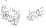
- FIG. 1is a perspective view showing a wheeled stretcher incorporating a drive assembly including a floor-engaging wheel for propelling the stretcher along a floor in accordance with the present invention
- FIG. 1 ais a perspective view of a portion of the stretcher of FIG. 1 , showing a rechargeable battery, a recessed battery compartment in a lower frame configured for receiving the battery and a main power switch mounted on the lower frame adjacent to the battery compartment,
- FIG. 2is a partial perspective view, with portions broken away, showing a linkage assembly for lifting and lowering the wheel, and a drive assembly drivingly couplable to the wheel for propelling the stretcher along the floor, the linkage assembly having a neutral position (shown in FIGS. 3 and 7 ) in which the wheel is spaced apart from the floor and a steer position (shown in FIGS. 5 and 8 ) in which the wheel is engaging the floor, and the drive assembly having a first mode of operation (shown in FIGS. 5 and 8 ) decoupled from the wheel so that the wheel is free to rotate when the stretcher is manually pushed along the floor without hindrance from the drive assembly and a second mode of operation (shown in FIGS. 9 and 10 ) coupled to the wheel to drive the wheel to propel the stretcher along the floor,
- a neutral positionshown in FIGS. 3 and 7
- a steer positionshown in FIGS. 5 and 8
- the drive assemblyhaving a first mode of operation (shown in FIGS. 5 and 8 )
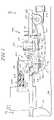
- FIG. 3is a side elevation view showing the linkage and drive assemblies of FIG. 2 , the linkage assembly being shown in the neutral position with the wheel spaced apart from the floor, and further showing the drive assembly in the first mode of operation decoupled from the wheel, the drive assembly including a belt coupling a drive motor to the wheel and a belt tensioner to selectively tension the belt, the belt tensioner including a support bracket, an idler pulley (hereinafter idler) coupled to the support bracket, and an actuator having a first orientation (shown in FIGS. 3 , 5 , 7 and 8 ) in which the idler is spaced apart from the belt to decouple the drive motor from the wheel, and a second orientation (shown in FIGS. 9 and 10 ) in which the idler engages the belt to tension the belt to couple the drive motor to the wheel to propel the stretcher along the floor when the wheel is engaging the floor,
- the drive assemblyincluding a belt coupling a drive motor to the wheel and a belt tensioner to selectively tension the belt, the
- FIG. 4is a sectional view taken along line 4 — 4 in FIG. 3 , and showing the linkage assembly in the neutral position in which the wheel spaced apart from the floor,
- FIG. 5is a view similar to FIG. 3 , showing the linkage assembly in the steer position with the wheel engaging the floor, and further showing the actuator in the first orientation with the idler spaced apart from the belt to decouple the drive motor from the wheel so that the wheel is free to rotate when the stretcher is manually pushed along the floor without hindrance from the drive assembly,
- FIG. 6is a sectional view similar to FIG. 4 taken along line 6 — 6 in FIG. 5 , and showing the linkage assembly in the steer position in which the wheel engaging the floor,
- FIG. 7is a side elevation view corresponding to FIG. 3 , showing the linkage assembly in the neutral position with the wheel spaced apart from the floor, and the actuator in the first orientation with the idler spaced apart from the belt to decouple the drive motor from the wheel, and further showing the drive motor mounted on the lower frame, a wheel-mounting bracket supporting the wheel, the belt loosely coupled to the drive motor and the wheel, the idler support bracket carrying the idler pivotally coupled to the wheel-mounting bracket, and the actuator coupled to the idler support bracket,
- FIG. 8is a side elevation view corresponding to FIG. 5 , showing the linkage assembly in the steer position with the wheel engaging the floor, and the actuator in the first orientation with the idler spaced apart from the belt to decouple the drive motor from the wheel so that the wheel is free to rotate when the stretcher is manually pushed along the floor without hindrance from the drive motor,
- FIG. 9is a view similar to FIG. 8 , showing the linkage assembly in the steer position with the wheel engaging the floor, and the actuator in the second orientation with the idler engaging the belt to tension the belt to propel the stretcher along the floor,
- FIG. 10is a sectional end view taken along line 10 — 10 in FIG. 9 , showing the linkage assembly in the steer position with the wheel engaging the floor and the actuator in the second orientation to couple the drive motor to the wheel to propel the stretcher along the floor,
- FIG. 11is an end elevation view of the stretcher of FIG. 1 , showing the head end of a patient support deck mounted on the lower frame, a first push bar locked in an upward push position and having a handle post extending generally horizontally above the patient support deck, a second push bar locked in a down-out-of-the-way position having a handle post below the patient support deck, and a rotary switch coupled to a distal end of the handle post of the first push bar for operating the drive assembly,
- FIG. 12is an exploded perspective view of the rotary switch of FIG. 11 coupled to the distal end of the handle post of the first push bar,
- FIG. 13is a sectional view of the rotary switch of FIGS. 11 and 12 .
- FIG. 14is a block diagram, schematically showing the electrical components of the drive assembly
- FIG. 15is an exploded perspective view of an alternative push-type switch assembly configured to be coupled to the distal end of the handle post of the first push bar for operating the drive assembly, the push-type switch assembly including a pressure sensitive switch configured to be positioned inside the handle post and a flexible dome-shaped cap configured to be coupled to an input shaft of the pressure sensitive switch,
- FIG. 15 ais a view showing a forward/reverse switch configured to be coupled to a distal end of the handle post of the second push bar
- FIG. 16is a sectional view of the push-type switch assembly of FIG. 15 coupled to the distal end of the handle post of the first push bar,
- FIG. 17is a sectional view similar to FIG. 16 , showing the flexible dome-shaped cap of the push-type switch assembly pressed to push the input shaft of the pressure sensitive switch,
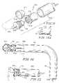
- FIG. 18is a perspective view of an alternative embodiment of the drive assembly drivingly couplable to a floor-engaging wheel for propelling the stretcher along the floor, and showing the wheel mounted directly on an output shaft of a drive motor coupled to the wheel-mounting bracket,
- FIG. 19is a sectional view of the drive motor and the wheel of FIG. 18 through the central axis of the motor output shaft,
- FIG. 20is a perspective view of another alternative embodiment of the drive assembly drivingly couplable to a floor-engaging wheel for propelling the stretcher along the floor, showing the wheel mounted directly on a rim portion of a rotor of a drive motor, and further showing a stationary shaft of a stator of the drive motor fixed to the wheel-mounting bracket, and
- FIG. 21is a sectional view of the drive motor and the wheel of FIG. 20 through the central axis of the stationary stator shaft.
- the present inventionwill be described in conjunction with a hospital stretcher, but it will be understood that the same may be used in conjunction with any patient support apparatus, such as an ambulatory chair.
- a stretcher 20 in accordance with the present inventionincludes a frame 22 , comprising an upper frame 24 and a lower frame 26 , a shroud 28 covering the lower frame 26 , a head end 30 , a foot end 32 , an elongated first side 34 , and an elongated second side 36 .
- the phrase “head end 30 ”will be used to denote the end of any referred-to object that is positioned to lie nearest the head end 30 of the stretcher 20
- the phrase “foot end 32 ”will be used to denote the end of any referred-to object that is positioned to lie nearest the foot end 32 of the stretcher 20 .
- first side 34will be used to denote the side of any referred-to object that is positioned to lie nearest the first side 34 of the stretcher 20 and the phrase “second side 36 ” will be used to denote the side of any referred-to object that is positioned to lie nearest the second side 36 of the stretcher 20 .
- the upper frame 24is movably supported above the lower frame 26 by a lifting mechanism 38 for raising, lowering, and tilting the upper frame 24 relative to the lower frame 26 .
- the lifting mechanism 38includes head end and foot end hydraulic cylinders 40 and 42 , which are covered by flexible rubber boots 44 .
- the head end hydraulic cylinder 40controls the vertical position of the head end 30 of the upper frame 24 relative to the lower frame 26
- the foot end hydraulic cylinder 42controls the vertical position of the foot end 32 of the upper frame 24 relative to the lower frame 26 .
- a patient support deck 50is carried by the upper frame 24 and has a head end 30 , a foot end 32 , a first elongated side 34 , and a second elongated side 36 .
- a mattress 52 having an upwardly-facing patient support surface 54is supported by the patient support deck 50 .
- a pair of collapsible side rails 56are mounted to the upper frame 24 adjacent to the first and second elongated sides 34 , 36 of the patient support deck 50 .
- An IV pole 58 for holding solution containers or other objects at a position elevated above the patient support surface 54is pivotably attached to the upper frame 24 , and can be pivoted between a lowered horizontal position alongside the patient support deck 50 and a generally vertical raised position shown in FIG. 1 .
- Casters 60are mounted to the lower frame 26 , one at each corner, so that the stretcher 20 can be rolled over a floor 62 across which a patient is being transported.
- Several foot pedals 70are pivotably coupled to the lower frame 26 and are coupled to the lifting mechanism 38 to control the vertical movement of the head end 30 and the foot end 32 of the upper frame 24 relative to the lower frame 26 .
- a brake pedal 72is coupled to the lower frame 26 near the foot end 32 thereof to control the braking of the casters 60 .
- a brake-steer butterfly pedal 74is coupled to the lower frame 26 near the head end 30 thereof to control both the braking of the casters 60 , and the release of the braked casters 60 .
- Each of the foot pedals 70 , brake pedal 72 , and brake-steer pedal 74extends outwardly from the lower frame 26 .
- a first push bar 80is pivotally mounted to the head end 30 of the upper frame 24 below the patient support deck 50 adjacent to the first elongated side 34 of the patient support deck 50 .
- a second push bar 82is pivotally mounted to the head end 30 of the upper frame 24 below the patient support deck 50 adjacent to the second elongated side 36 of the patient support deck 50 .
- Each of the first and second push bars 80 , 82is independently movable between a raised push position shown in FIGS. 1 and 11 , and a lowered down-out-of-the-way position shown in FIG. 11 .
- the first and second push bars 80 , 82each include a handle post 84 that is grasped by the caregiver when the first and second push bars 80 , 82 are in the raised push position to manually push the stretcher 20 over the floor 62 .
- the push bars 80 , 82are in the down-out-of-the-way position, the push bars 80 , 82 are below and out of the way of the patient support surface 54 , thus maximizing the caregiver's access to a patient on the patient support surface 54 .
- the stretcher 20includes the brake pedal 72 positioned at the foot end 32 of the stretcher 20 , and the brake-steer pedal 74 positioned at the head end 30 of the stretcher 20 .
- a brake-steer shaft 88extends longitudinally along the length of the stretcher 20 on the first side 34 thereof underneath the shroud 28 , and is connected to both the brake pedal 72 at the foot end 32 and the brake-steer pedal 74 at the head end 30 . Movement of either the brake pedal 72 or the brake-steer pedal 74 by a caregiver causes the brake-steer shaft 88 to rotate about a longitudinal pivot axis 90 .
- the brake-steer shaft 88is in a neutral position shown in solid lines in FIG.
- the brake-steer pedal 74is generally horizontal as shown in FIG. 1 , and the casters 60 are free to swivel and rotate. From the generally horizontal neutral position, the caregiver can depress the brake pedal 72 or a braking portion 92 of the brake-steer pedal 74 to rotate the brake-steer shaft 88 in an anticlockwise, braking direction indicated by arrow 94 in FIG. 4 to a brake position shown in phantom in FIG. 4 . In the braking position, the braking portion 92 of the brake-steer pedal 74 is angled downwardly toward the first side 34 of the stretcher 20 , and a steering portion 96 of the brake-steer pedal 74 is angled upwardly. Rotation of the brake-steer shaft 88 to the brake position moves brake shoes into engagement with the casters 60 to stop rotation and swiveling movement of the casters 60 .
- the caregivercan depress a steering portion 96 of the brake-steer pedal 74 to rotate the brake-steer shaft 88 in a clockwise direction back to the neutral position shown in solid lines in FIG. 4 .
- the caregivercan depress the steering portion 96 of the brake-steer pedal 74 to rotate the brake-steer shaft 88 in a clockwise, steering direction indicated by arrow 98 shown in FIG. 6 to a steer position shown in FIG. 6 .
- the braking portion 92 of the brake-steer pedal 74is angled upwardly, and the steering portion 96 of the brake-steer pedal 74 is angled downwardly toward the second side 36 of the stretcher 20 .
- a linkage assembly 100is provided for lifting and lowering a wheel 110 .
- the linkage assembly 100has (i) a neutral position (shown in FIGS. 3 and 7 ) in which the wheel 110 is raised above the floor 62 a first distance, (ii) a brake position (shown in phantom in FIG. 4 ) in which the wheel 110 is raised above the floor 62 a second higher distance, and (iii) steer position (shown in FIGS. 5 and 8 – 10 ) in which the wheel 110 is engaging the floor 62 .
- the floor-engaging wheel 110serves a dual purpose—(a) it facilitates steering of the stretcher 20 , and (b) it drives the stretcher 20 along the floor 62 in a power drive mode. Referring to FIGS.
- the wheel 110is mounted on an axle 112 coupled to the lower frame 26 by a wheel-mounting bracket 114 .
- the wheel-mounting bracket 114is, in turn, coupled to the brake-steer shaft 88 .
- Rotation of the brake-steer shaft 88changes the position of the wheel 110 relative to the floor 62 .
- the wheel-mounting bracket 114holds the wheel 110 above the floor 62 a first distance (approximately 0.5 inches (1.3 cm)) as shown in FIG. 3 .
- the linkage assembly 100pivots the wheel-mounting bracket 114 upwardly to further lift the wheel 110 above the floor 62 a second higher distance (approximately 3.5 inches (8.9 cm)) to allow equipment, such as the base of an overbed table (not shown), to be positioned underneath the wheel 110 .
- the linkage assembly 100pivots the wheel-mounting bracket 114 downwardly to lower the wheel 110 to engage the floor 62 as shown in FIG. 5 and 8 - 10 .
- the wheel-mounting bracket 114includes a first outer fork 120 , and a second inner fork 122 .
- a foot end 32 of the first fork 120that is the end of the first fork 120 closer to the foot end 32 of the stretcher 20 , is pivotably coupled to the lower frame 26 for pivoting movement about a first transverse pivot axis 124 .
- a head end of the first fork 120that is the end of the first fork 120 closer to the head end 30 of the stretcher 20 , is pivotably coupled to the second fork 122 for rotation about a second transverse pivot axis 126 .
- a head end portion 130 of the second fork 122extends from the second transverse pivot axis 126 toward the head end 30 of the stretcher 20 .
- the wheel 110is coupled to the head end portion 130 of the second fork 122 for rotation about an axis of rotation 128 .
- a foot end portion 132 of the second fork 122extends from the second transverse pivot axis 126 toward the foot end 32 of the stretcher 20 , and is received by a space formed by two spaced-apart prongs of the first fork 120 .
- An end plate 134is fixed to the foot end portion 132 of the second fork 122 .
- a vertically oriented spring 136connects the end plate 134 to a frame bracket 138 mounted to the lower frame 26 .
- the spring 136yieldably biases the end plate 134 and the foot end portion 132 of the second fork 122 upwardly, so that the head end portion 130 of the second fork 122 and the wheel 110 are yieldably biased downwardly.
- the end plate 134has a pair of transversely extending barbs 140 shown in FIGS.
- the barbs 140stop the upward movement of the end plate 134 at the in-line configuration to limit the downward movement of the head end portion 130 of the second fork 122 and the wheel 110 relative to the first fork 120 as the spring 136 biases the end plate 134 of the second fork 122 upwardly.
- the spring 136biases the second fork 122 away from the angled configuration and toward the in-line configuration, so that the wheel 110 is biased to a position past the plane defined by the bottoms of the casters 60 when the wheel 110 is lowered for engaging the floor 62 .
- the floor 62limits the downward movement of deployed wheel 110 .
- the spring 136cooperates with the first and second forks 120 , 122 to maintain contact between the wheel 110 and the floor 62 .
- the spring 136can maintain engagement between the deployed wheel 110 and the floor 62 when the floor 62 beneath the wheel 110 is spaced approximately 1 inch (2.5 cm) below the plane defined by the casters 60 . Also, the spring 136 allows the deployed wheel 110 to pass over a threshold that is approximately 1 inch (2.5 cm) above the plane defined by the casters 60 without causing the wheel 110 to move out of the steer position into the neutral position.
- the linkage assembly 100includes an upper bent-cross bracket 144 coupled to the frame bracket 138 , and supporting an upper pivot pin 146 .
- the linkage assembly 100includes a lower bent-cross bracket 148 coupled to the wheel-mounting bracket 114 , and supporting a lower pivot pin 150 .
- the linkage assembly 100includes (i) a pivot link 152 fixed to the brake-steer shaft 88 , (ii) a connecting link 154 extending from the pivot link 152 to a common pivot pin 156 , (iii) a frame link 158 extending from the common pivot pin 156 to the upper pivot pin 146 of the upper bent-cross bracket 144 , and (iv) a bracket link 160 extending from the common pivot pin 156 to the lower pivot pin 150 of the lower bent-cross bracket 148 .
- the frame link 158 and the bracket link 160form a scissors-like arrangement as shown in FIGS. 2 , 4 and 6 .
- the pivot link 152pivots away from the wheel-mounting bracket 114 , pulling the connecting link 154 and the common pivot pin 156 toward the brake-steer shaft 88 in the direction indicated by arrow 162 shown in FIG. 4 .
- the upper bent-cross bracket 144is vertically fixed relative to the lower frame 26 and the lower bent-cross bracket 148 is fixed to the wheel-mounting bracket 114 , which is pivotably mounted to the lower frame 26 for upward and downward pivoting movement relative to the lower frame 26 .
- Movement of the common pivot pin 156 in the direction 162closes the scissors arrangement formed by the frame link 158 and the bracket link 160 as shown in phantom in FIG. 4 , pulling the bracket link 160 upwardly.
- Pulling the bracket link 160 upwardlypivots the wheel-mounting bracket 114 in the direction of arrow 164 shown in FIG. 3 , and further lifts the wheel 110 off of the floor 62 .
- the pivot link 152contacts a frame member 170 coupled to the lower frame 26 , stopping the brake-steer shaft 88 from further rotation in the clockwise direction as shown in FIG. 6 .
- the common pivot pin 156is in an “over-the-center position” away from the brake-steer shaft 88 and beyond a vertical plane 172 (shown in FIG. 6 ) defined by the upper and lower pivot pins 146 and 150 , so that the scissors arrangement formed by the frame link 158 and bracket link 160 is in a generally fully-opened position.
- the stretcher 20includes the brake pedal 72 and the brake-steer pedal 74 connected to the longitudinally extending brake-steer shaft 88 .
- Actuation of the brake pedal 72 or the brake-steer pedal 74 by the caregiversimultaneously controls the position of wheel 110 and the braking of casters 60 .
- the brake-steer pedal 74has a horizontal neutral position where the wheel 110 is at the first distance above the floor 62 and the casters 60 are free to rotate and swivel.
- the caregivercan push the brake pedal 72 or the braking portion 92 of the brake-steer pedal 74 down to rotate the brake-steer shaft 88 by about 30 degrees to the brake position to brake the casters 60 .
- the pivot link 152pivots away from the wheel-mounting bracket 114 pulling the connecting link 154 and the common pivot pin 156 in the direction 162 (shown in FIG. 4 ) and closing the scissors arrangement of the frame link 158 and the bracket link 160 to lift the wheel 110 to the second higher distance above the floor 62 .
- the caregivercan also push the steering portion 96 of the brake-steer pedal 74 down to rotate the brake-steer shaft 88 by about 30 degrees past the neutral position to the steer position in which the casters 60 are free to rotate and swivel.
- the pivot link 152pivots toward the wheel-mounting bracket 114 pushing the connecting link 154 and the common pivot pin 156 in the direction 166 (shown in FIG. 6 ) and opening the scissors arrangement formed by the frame link 158 and the bracket link 160 to deploy the wheel 110 to engage floor 62 with enough pressure to facilitate steering of the stretcher 20 .
- the second fork 122 of the wheel-mounting bracket 114pivots relative to the first fork 120 and relative to the lower frame 26 .
- the wheel 110is spring-biased into engagement with the floor 62 with sufficient force to permit the wheel 110 to track differences in elevation of the floor 62 .
- U.S. patent applicationSer. No. 09/150,890, entitled “STRETCHER CENTER WHEEL MECHANISM”, for further description of the linkage assembly 100 for lifting and lowering the wheel 110 .
- the drive assembly 200includes a variable speed, bidirectional drive motor 202 having a rotatable output shaft 204 , and a selectively engagable clutch 206 to selectively couple the drive motor 202 to the wheel 110 when the clutch 206 is engaged.
- the wheel 110has three positions—(i) a neutral position in which the wheel 110 is raised the first distance above the floor 62 as shown in FIGS.
- the drive assembly 200has (a) a first, manual drive mode of operation decoupled from the wheel 110 (when the clutch is disengaged as shown in FIGS. 5 and 8 ) so that the wheel 110 is free to rotate when the stretcher 20 is manually pushed along the floor 62 without hindrance from the drive motor 202 , and (b) a second, power drive mode of operation coupled to the wheel 110 (when the clutch is engaged as shown in FIGS. 9 and 10 ) to drive the wheel 110 to propel the stretcher 20 along the floor 62 .
- the selectively engagable clutch 206includes a drive pulley 208 mounted on the rotatable output shaft 204 of the drive motor 202 , a driven pulley 210 coaxially mounted on the axle 112 and coupled to the wheel 110 , a slipbelt 212 (also referred to herein as belt 212 ) extending loosely between and around the drive pulley 208 and the driven pulley 210 , an idler 214 having a first position (shown in FIGS. 5 and 8 ) spaced apart from or lightly contacting the belt 212 and a second position (shown in FIGS.
- a support bracket 216pivotally mounted to the head end portion 130 of the wheel-mounting bracket 114 about a pivot pin 218 , an actuator 220 mounted to the lower frame 26 , and a gas spring 222 having its ends 224 and 226 pivotally coupled to the support bracket 216 and an output member 228 threadably engaging a rotatable output shaft 230 of the actuator 220 .
- the support bracket 216 , the actuator 220 and the gas spring 222are sometimes referred to herein as a second assembly or second linkage assembly.
- the language “idler 214 is spaced apart from the slipbelt 212 ” or “idler 214 is lightly contacting the slipbelt 212 ”is used for convenience only to connote that the slipbelt 212 is not in tension and the drive motor 202 is decoupled from the wheel 110 as shown in FIGS. 5 and 8 .
- the language “idler 214 is spaced apart from the slipbelt 212 ” or “idler 214 is lightly contacting the slipbelt 212 ”is to be construed to mean that the drive motor 202 is decoupled from the wheel 110 , and not to be construed to limit the scope of the invention.
- the support bracket 216In the manual drive mode, when the wheel 110 is engaging the floor 62 and the clutch 206 is disengaged as shown in FIGS. 5 and 8 , the support bracket 216 has a first orientation in which the idler 214 is spaced apart from or lightly contacting the belt 212 so that the wheel 110 is free to rotate when the stretcher 20 is manually pushed along the floor 62 without hindrance from the drive motor 202 . In the power drive mode, when the wheel 110 is engaging the floor 62 and the clutch 206 is engaged as shown in FIGS. 9 and 10 , the support bracket 216 has a second orientation in which the idler 214 is pressed against the belt 212 to transfer rotation from the drive motor 202 to the wheel 110 to propel the stretcher 20 along the floor 62 .
- a power sourcesuch as a rechargeable battery 242
- a rechargeable battery 242is inserted into a recessed battery compartment 244 formed in the lower frame 26 as shown in FIG. 1 a for supplying power to the drive motor 202 and the actuator 220 .
- the battery compartment 244has terminals 246 for engagement with corresponding terminals 248 on the rechargeable battery 242 when the battery 242 is inserted in the battery compartment 244 .
- a main, on/off power switch 250is mounted on the lower frame 26 away from the patient support deck 50 for connecting and disconnecting the drive motor 202 and the actuator 220 to and from the battery 242 .
- a limit switch 252is mounted on the lower frame 26 next to the linkage assembly 100 , as shown in FIGS.
- a rotary switch assembly 254is coupled to a distal end 86 of the handle post 84 of the first push bar 80 as shown in FIGS. 1 and 11 for controlling the speed and direction of the variable speed, bidirectional drive motor 202 .
- the stretcher 20is in the manual drive mode when the wheel 110 is engaging the floor 62 , but the main power switch 250 on the lower frame 26 is switched off as shown in FIGS. 5 and 8 .
- the actuator 220remains inactivated allowing the belt 212 to ride loosely over the drive and driven pulleys 208 and 210 to permit the wheel 110 to rotate freely when the stretcher 20 is manually pushed along the floor 62 without interference from the drive assembly 200 .
- the stretcher 20is in the power drive mode when the wheel 110 is engaging the floor 62 , and the main power switch 250 on the lower frame 26 is turned on as shown in FIGS. 9 and 10 .
- the actuator 220is activated to press the idler 214 against the belt 212 to couple the drive motor 202 to the wheel 110 to propel the stretcher 20 along the floor 62 in response to the operation of the rotary switch assembly 254 on the handle post 84 .
- a generally vertically oriented spring 232( FIGS. 3 , 5 and 7 ) coupled between a head end 30 of the idler support bracket 216 and the lower frame 26 helps to fully lift the linkage assembly 100 off the floor 62 when in neutral or brake positions.
- the vertically oriented spring 232may be coupled between a head end 30 of the wheel-mounting bracket 114 and the lower frame 26 .
- Guide rollers(not shown) are provided to prevent the belt 212 from slipping off the drive and driven pulleys 208 and 210 .
- the gas spring 222When the actuator 220 is activated to press the idler 214 against the belt 212 , the gas spring 222 is compressed as shown in FIGS. 9 and 10 to provide additional downward biasing force between the wheel 110 and the floor 62 .
- the additional downward biasing force exerted by the compressed gas spring 222is between seventy five pounds and one hundred pounds.
- FIG. 14schematically shows the electrical system 240 for the drive assembly 200 .
- the limit switch 252senses when the wheel 110 is lowered for engaging the floor 62 , and provides an input signal to a controller 256 .
- the controller 256activates the actuator 220 when the main power switch 250 is turned on and the limit switch 252 senses that the wheel 110 is engaging the floor 62 .
- the actuator 220is turned on, the output member 228 of the actuator 220 is translated in the direction of arrow 258 (shown in FIG. 8 ) to cause the support bracket 216 to pivot clockwise about the pivot pin 218 to press the idler 214 against the belt 212 as shown in FIG. 9 to transfer rotation from the drive motor 202 to the wheel 110 .
- the drive motor 202then propels the stretcher 20 along the floor 62 in response to the operation of the rotary switch assembly 254 .
- the rotary switch assembly 254is rotated to a forward position for forward motion of the stretcher 20 and is rotated to a reverse position for reverse motion of the stretcher 20 .
- the speed of the variable speed drive motor 202is determined by the extent of rotation of the rotary switch assembly 254 .
- FIG. 12is an exploded perspective view of the rotary switch assembly 254
- FIG. 13is a sectional view of the rotary switch assembly 254
- the distal end 86 of the handle post 84includes a generally cylindrical hollow tube 260 defining an axis 262
- the rotary switch assembly 254includes a bidirectional rotary switch 264 positioned inside the hollow tube 260 to rotate about the axis 262 . Control wires 266 of the rotary switch 264 are routed through the hollow tube 260 for connection to the controller 256 .
- the rotary switch 264includes an input shaft 268 which is configured to be inserted into a chuck 270 coupled to an inner end of a control shaft 272 .
- a thumb wheel 274is coupled to an outer end of the chuck 270 by a set screw 276 .
- the control shaft 272is inserted into an outer sleeve 278 through an outer end thereof.
- the rotary switch 264includes a threaded portion 280 that is screwed into a flange portion 282 formed at an inner end of the outer sleeve 278 .
- the outer sleeve 278is configured to be press fitted into the hollow tube 260 formed at the distal end 86 of the handle post 84 as shown in FIG. 13 .
- the rotary switch assembly 254is biased toward a neutral position between the forward and reverse positions thereof.
- the control shaft 272is formed to include wedge-shaped camming surfaces 284 which are configured to cooperate with corresponding, notch-shaped camming surfaces 286 formed in an inner sleeve 288 slidably received in the outer sleeve 278 .
- the inside surface of the outer sleeve 278is formed to include raised guide portions 290 which are configured to be received in corresponding guide grooves 292 formed on the outer surface of the inner sleeve 288 .
- a spring 294is disposed between the inner sleeve 288 and the flange portion 282 of the outer sleeve 278 .
- the spring 294biases the camming surfaces 286 of the inner sleeve 288 into engagement with the camming surfaces 284 of the control shaft 272 to, in turn, bias the thumb wheel 274 to automatically return to a neutral position thereof when released.
- the thumb wheel 274is movable to a forward position in which the drive assembly 200 operates to drive the wheel 110 in a forward direction to propel the stretcher 20 in the forward direction, and the thumb wheel 274 is movable to a reverse position in which the drive assembly 200 operates to drive the wheel 110 in a reverse direction to propel the stretcher 20 in the reverse direction.
- the handle post 84may be marked with an indicia to provide a visual indication of the neutral position of the thumb wheel 274 .
- the drive motor 202is Model No. M6030/G33, manufactured by Rae Corporation
- the linear actuator 220is Model No. LA22.1-130-24-01, manufactured by Linak Corporation
- the rotary switch 264is Model No. RV6N502C-ND, manufactured by Precision Corporation.
- FIGS. 15–17show an alternative push-type switch assembly 300 for operating the drive motor 202 .
- the push-type switch assembly 300is coupled to the distal end 86 of the handle post 84 of the first push bar 80 .
- the push-type switch assembly 300includes a pressure sensitive, push-type switch 302 positioned inside the hollow tube 260 formed at the distal end 86 of the handle post 84 .
- Control cables 304 of the push-type switch 302are routed through the hollow tube 260 for connection to the controller 256 .
- the push-type switch 302includes a threaded portion 306 that is screwed into a threaded portion 308 formed on the inside surface of an outer sleeve 310 .
- the outer sleeve 310is configured to be press fitted into the hollow tube 260 of the handle post 84 as shown in FIGS. 16 and 17 .
- the push-type switch 302includes an input shaft 312 which is configured to be in engagement with a flexible dome-shaped cap 314 .
- the flexible dome-shaped cap 314is snap fitted over a flange portion 316 of the outer sleeve 310 .
- a forward/reverse toggle switch 318is mounted near a distal end 86 of the second push bar 82 to change the direction of the drive motor 202 as shown in FIG. 15 a .
- the forward/reverse toggle switch 318may be located at some other location—for example, the lower frame 26 .
- the forward/reverse toggle switch 318is moved to a forward position in which the drive motor 202 operates to drive the wheel 110 in a forward direction to propel the stretcher 20 in the forward direction, and the forward/reverse toggle switch 318 is moved to a reverse position in which the drive motor 202 operates to drive the wheel 110 in a reverse direction to propel the stretcher 20 in the reverse direction.
- the speed of the drive motor 202is determined by the extent to which the push-type switch 302 is pushed.
- the push-type switch 302is of the type sold by Duncan Corporation.
- FIGS. 18 and 19show an alternative configuration of the drive assembly 350 drivingly couplable to the wheel 110 for propelling the stretcher 20 along the floor 62 .
- the wheel 110is mounted directly on an output shaft 352 of a drive motor 354 .
- the drive motor 354is, in turn, mounted to a bracket 356 coupled to the wheel-mounting bracket 114 .
- Control cables 358 of the drive motor 354are routed to the controller 256 along the wheel-mounting bracket 114 .
- the drive motor 354is of the type sold by Rockland Corporation.
- FIGS. 19 and 20show another alternative configuration of the drive assembly 400 drivingly couplable to the wheel 110 for propelling the stretcher 20 along the floor 62 .
- the wheel 110is mounted directly on a rim portion 402 of a rotor 404 of a hub-type drive motor 406 .
- the stationary stator shaft 408 of the hub-type drive motor 406is coupled to the wheel-mounting bracket 114 .
- Control cables 410 of the drive motor 406are routed to the controller 256 along the wheel-mounting bracket 114 .
- the hub-type drive motor 406is Model No. 80-200-48-850, manufactured by PML Manufacturing Company.
Landscapes
- Health & Medical Sciences (AREA)
- Life Sciences & Earth Sciences (AREA)
- Animal Behavior & Ethology (AREA)
- General Health & Medical Sciences (AREA)
- Public Health (AREA)
- Veterinary Medicine (AREA)
- Nursing (AREA)
- Invalid Beds And Related Equipment (AREA)
- Handcart (AREA)
Abstract
Description
Claims (20)
Priority Applications (5)
| Application Number | Priority Date | Filing Date | Title |
|---|---|---|---|
| US10/998,329US7011172B2 (en) | 1999-09-15 | 2004-11-23 | Patient support apparatus having a motorized wheel |
| US11/351,720US7284626B2 (en) | 1999-09-15 | 2006-02-10 | Patient support apparatus with powered wheel |
| US11/874,273US7530412B2 (en) | 1999-09-15 | 2007-10-18 | Method of making and using a patient support apparatus having a motorized drive assembly |
| US12/429,349US8240410B2 (en) | 1999-09-15 | 2009-04-24 | Patient support apparatus with powered wheel |
| US13/400,363US8397846B2 (en) | 1999-09-15 | 2012-02-20 | Patient support apparatus with powered wheel |
Applications Claiming Priority (5)
| Application Number | Priority Date | Filing Date | Title |
|---|---|---|---|
| US15408999P | 1999-09-15 | 1999-09-15 | |
| US09/434,948US6330926B1 (en) | 1999-09-15 | 1999-11-05 | Stretcher having a motorized wheel |
| US10/022,552US6588523B2 (en) | 1999-09-15 | 2001-12-17 | Stretcher having a motorized wheel |
| US10/431,205US6902019B2 (en) | 1999-09-15 | 2003-05-07 | Stretcher having a motorized wheel |
| US10/998,329US7011172B2 (en) | 1999-09-15 | 2004-11-23 | Patient support apparatus having a motorized wheel |
Related Parent Applications (1)
| Application Number | Title | Priority Date | Filing Date |
|---|---|---|---|
| US10/431,205ContinuationUS6902019B2 (en) | 1999-09-15 | 2003-05-07 | Stretcher having a motorized wheel |
Related Child Applications (1)
| Application Number | Title | Priority Date | Filing Date |
|---|---|---|---|
| US11/351,720ContinuationUS7284626B2 (en) | 1999-09-15 | 2006-02-10 | Patient support apparatus with powered wheel |
Publications (2)
| Publication Number | Publication Date |
|---|---|
| US20050072610A1 US20050072610A1 (en) | 2005-04-07 |
| US7011172B2true US7011172B2 (en) | 2006-03-14 |
Family
ID=26851136
Family Applications (8)
| Application Number | Title | Priority Date | Filing Date |
|---|---|---|---|
| US09/434,948Expired - LifetimeUS6330926B1 (en) | 1999-09-15 | 1999-11-05 | Stretcher having a motorized wheel |
| US10/022,552Expired - LifetimeUS6588523B2 (en) | 1999-09-15 | 2001-12-17 | Stretcher having a motorized wheel |
| US10/431,205Expired - LifetimeUS6902019B2 (en) | 1999-09-15 | 2003-05-07 | Stretcher having a motorized wheel |
| US10/998,329Expired - LifetimeUS7011172B2 (en) | 1999-09-15 | 2004-11-23 | Patient support apparatus having a motorized wheel |
| US11/351,720Expired - LifetimeUS7284626B2 (en) | 1999-09-15 | 2006-02-10 | Patient support apparatus with powered wheel |
| US11/874,273Expired - Fee RelatedUS7530412B2 (en) | 1999-09-15 | 2007-10-18 | Method of making and using a patient support apparatus having a motorized drive assembly |
| US12/429,349Expired - Fee RelatedUS8240410B2 (en) | 1999-09-15 | 2009-04-24 | Patient support apparatus with powered wheel |
| US13/400,363Expired - Fee RelatedUS8397846B2 (en) | 1999-09-15 | 2012-02-20 | Patient support apparatus with powered wheel |
Family Applications Before (3)
| Application Number | Title | Priority Date | Filing Date |
|---|---|---|---|
| US09/434,948Expired - LifetimeUS6330926B1 (en) | 1999-09-15 | 1999-11-05 | Stretcher having a motorized wheel |
| US10/022,552Expired - LifetimeUS6588523B2 (en) | 1999-09-15 | 2001-12-17 | Stretcher having a motorized wheel |
| US10/431,205Expired - LifetimeUS6902019B2 (en) | 1999-09-15 | 2003-05-07 | Stretcher having a motorized wheel |
Family Applications After (4)
| Application Number | Title | Priority Date | Filing Date |
|---|---|---|---|
| US11/351,720Expired - LifetimeUS7284626B2 (en) | 1999-09-15 | 2006-02-10 | Patient support apparatus with powered wheel |
| US11/874,273Expired - Fee RelatedUS7530412B2 (en) | 1999-09-15 | 2007-10-18 | Method of making and using a patient support apparatus having a motorized drive assembly |
| US12/429,349Expired - Fee RelatedUS8240410B2 (en) | 1999-09-15 | 2009-04-24 | Patient support apparatus with powered wheel |
| US13/400,363Expired - Fee RelatedUS8397846B2 (en) | 1999-09-15 | 2012-02-20 | Patient support apparatus with powered wheel |
Country Status (9)
| Country | Link |
|---|---|
| US (8) | US6330926B1 (en) |
| EP (2) | EP2198819B1 (en) |
| JP (1) | JP2003509123A (en) |
| AT (1) | ATE461685T1 (en) |
| AU (1) | AU7347700A (en) |
| BR (1) | BR0014028A (en) |
| CA (1) | CA2381795A1 (en) |
| DE (1) | DE60044062D1 (en) |
| WO (1) | WO2001019313A1 (en) |
Cited By (29)
| Publication number | Priority date | Publication date | Assignee | Title |
|---|---|---|---|---|
| US20080035396A1 (en)* | 1999-09-15 | 2008-02-14 | Heimbrock Richard H | Method of making and using a patient support apparatus having a motorized drive assembly |
| US20080086815A1 (en)* | 2006-10-13 | 2008-04-17 | Kappeler Ronald P | User Interface and Control System for Powered Transport Device of a Patient Support Apparatus |
| US20080115987A1 (en)* | 2005-02-11 | 2008-05-22 | Hans-Peter Barthelt | Wheelchair Comprising a Remote Control |
| US20080141459A1 (en)* | 2006-10-13 | 2008-06-19 | Hamberg Stephen R | Push handle with rotatable user interface |
| EP1985275A2 (en) | 2007-04-26 | 2008-10-29 | Hill-Rom Services, Inc. | Patient care equipment support transfer system |
| US20080283329A1 (en)* | 2000-05-11 | 2008-11-20 | John David Vogel | Motorized traction device for a patient support |
| US20080302608A1 (en)* | 2007-05-29 | 2008-12-11 | Linde Material Handling Gmbh | Fork-Lift Truck |
| US20090000834A1 (en)* | 2005-12-16 | 2009-01-01 | Enrico Carletti | Device for the Assisted Loading of Stretcher |
| US20090188731A1 (en)* | 2008-01-29 | 2009-07-30 | Zerhusen Robert M | Push handle with pivotable handle post |
| US20100126793A1 (en)* | 2008-05-22 | 2010-05-27 | Flowers Michael J | Power wheel chair |
| US20110087416A1 (en)* | 2009-10-12 | 2011-04-14 | Stryker Corporation | Speed control for patient handling device |
| US20110083270A1 (en)* | 2009-09-10 | 2011-04-14 | Bhai Aziz A | Powered transport system and control methods |
| US7953537B2 (en) | 2008-02-29 | 2011-05-31 | Hill-Rom Services, Inc. | Algorithm for power drive speed control |
| US20120198620A1 (en)* | 2011-02-08 | 2012-08-09 | Hornbach David W | Motorized center wheel deployment mechanism for a patient support |
| US20120199405A1 (en)* | 2005-12-16 | 2012-08-09 | Ferno-Washington, Inc. | Devices For The Assisted Loading Of A Stretcher |
| US8752659B1 (en) | 2011-12-30 | 2014-06-17 | Thomas E. Lenkman | Drive unit for a carrier |
| US9707143B2 (en) | 2012-08-11 | 2017-07-18 | Hill-Rom Services, Inc. | Person support apparatus power drive system |
| US10377403B2 (en)* | 2015-11-06 | 2019-08-13 | Caster Concepts, Inc. | Powered utility cart and compliant drive wheel therefor |
| US10507148B2 (en)* | 2014-11-13 | 2019-12-17 | Kap Medical, Inc. | Powered drive bed systems and methods |
| US10799403B2 (en) | 2017-12-28 | 2020-10-13 | Stryker Corporation | Patient transport apparatus with controlled auxiliary wheel deployment |
| US10945902B2 (en) | 2017-11-13 | 2021-03-16 | Stryker Corporation | Techniques for controlling actuators of a patient support apparatus |
| US11071662B2 (en) | 2017-12-28 | 2021-07-27 | Stryker Corporation | Patient transport apparatus with controlled auxiliary wheel speed |
| US11304860B2 (en) | 2018-11-21 | 2022-04-19 | Stryker Corporation | Patient transport apparatus with auxiliary wheel system |
| US11484447B2 (en) | 2018-11-21 | 2022-11-01 | Stryker Corporation | Patient transport apparatus with controlled auxiliary wheel deployment |
| US11806296B2 (en) | 2019-12-30 | 2023-11-07 | Stryker Corporation | Patient transport apparatus with controlled auxiliary wheel speed |
| US12178757B2 (en) | 2019-12-30 | 2024-12-31 | Stryker Corporation | Patient transport apparatus with auxiliary wheel control systems |
| US12208038B2 (en) | 2012-09-18 | 2025-01-28 | Stryker Corporation | Powered patient support apparatus |
| US12300838B2 (en) | 2021-11-09 | 2025-05-13 | Stryker Corporation | Patient support apparatus with battery retention system |
| US12370096B2 (en) | 2018-11-07 | 2025-07-29 | Hill-Rom Services, Inc. | Braking and steering system for a mobile support |
Families Citing this family (112)
| Publication number | Priority date | Publication date | Assignee | Title |
|---|---|---|---|---|
| US6598247B1 (en)* | 1999-10-27 | 2003-07-29 | Hill-Rom Services, Inc. | Stretcher with mechanical power assist |
| US6772850B1 (en) | 2000-01-21 | 2004-08-10 | Stryker Corporation | Power assisted wheeled carriage |
| WO2001062197A1 (en)* | 2000-02-28 | 2001-08-30 | Yamaha Hatsudoki Kabushiki Kaisha | Care type electric wheelchair |
| US7021407B2 (en) | 2000-05-11 | 2006-04-04 | Hill-Rom Services, Inc. | Motorized propulsion system for a bed |
| CN1899233A (en)* | 2000-05-11 | 2007-01-24 | 希尔-罗姆服务股份有限公司 | Motorized traction device for a patient support |
| US6554087B2 (en)* | 2001-02-08 | 2003-04-29 | Mattel, Inc. | Steering assembly for children's ride on vehicles |
| JP2005502433A (en) | 2001-09-20 | 2005-01-27 | ヒル−ロム サービシーズ,インコーポレイティド | Combination of bed mover and patient transfer device |
| US7018157B2 (en) | 2001-09-20 | 2006-03-28 | Hill-Rom Services, Inc. | Powered transport apparatus for a bed |
| US6902016B2 (en)* | 2001-11-01 | 2005-06-07 | Clark Equipment Company | Pivoting panel for mechanical control disengagement |
| WO2003057126A1 (en) | 2002-01-04 | 2003-07-17 | Hill-Rom Services, Inc. | Braking apparatus for a patient support |
| US6752224B2 (en) | 2002-02-28 | 2004-06-22 | Stryker Corporation | Wheeled carriage having a powered auxiliary wheel, auxiliary wheel overtravel, and an auxiliary wheel drive and control system |
| JP2004194844A (en)* | 2002-12-17 | 2004-07-15 | Paramount Bed Co Ltd | Electric transport device for bed and drive control method thereof |
| US7302717B2 (en)* | 2003-01-22 | 2007-12-04 | Hill-Rom Services, Inc. | Side and end brake/steer mechanism for stretchers |
| GB0309405D0 (en)* | 2003-04-24 | 2003-06-04 | Ferno Uk Ltd | Stretchers |
| US6725956B1 (en)* | 2003-05-06 | 2004-04-27 | Stryker Corporation | Fifth wheel for bed |
| ATE456351T1 (en) | 2003-05-21 | 2010-02-15 | Hill Rom Services Inc | HOSPITAL BED |
| US6792630B1 (en)* | 2003-09-11 | 2004-09-21 | Stryker Corporation | Fifth wheel assembly for bed |
| US7062805B2 (en)* | 2003-09-17 | 2006-06-20 | Stryker Corporation | Pedal control of brake and auxiliary wheel deployment via side and end articulation |
| IL158683A0 (en) | 2003-10-30 | 2004-05-12 | Savion Ind 1987 Ltd | Power-driven maneuverable platform |
| US7191854B2 (en)* | 2003-12-16 | 2007-03-20 | Lenkman Thomas E | Self propelled gurney and related structure confidential and proprietary document |
| JP2006001427A (en)* | 2004-06-17 | 2006-01-05 | Mitsuba Corp | Method for controlling conveying device with power assist, and conveying device with power assist |
| JP4535818B2 (en)* | 2004-09-22 | 2010-09-01 | パラマウントベッド株式会社 | Bed electric transfer device |
| JP5055523B2 (en)* | 2004-09-24 | 2012-10-24 | ストライカー コーポレイション | Ambulance simple bed and hydraulic lifting mechanism therefor |
| US7398571B2 (en) | 2004-09-24 | 2008-07-15 | Stryker Corporation | Ambulance cot and hydraulic elevating mechanism therefor |
| DE602005022224D1 (en)* | 2004-12-01 | 2010-08-19 | Borringia Ind Ag | WHEEL PROVIDED OBJECT FOR OPERATION THROUGH A GOING PERSON |
| US7311161B2 (en)* | 2005-06-14 | 2007-12-25 | Pao-Ling Lee | Hospital bed having a drive wheel unit |
| US9107788B2 (en)* | 2005-10-07 | 2015-08-18 | MediGlider Corp. | Cam mechanism to raise steering wheel of patient transfer device |
| US7698760B2 (en)* | 2005-11-17 | 2010-04-20 | Hill-Rom Services, Inc. | Hospital bed caster control system |
| US7810822B2 (en) | 2006-01-19 | 2010-10-12 | Hill-Rom Services, Inc. | Stretcher having hand actuated caster braking apparatus |
| DE602007009137D1 (en)* | 2006-01-19 | 2010-10-28 | Hill Rom Services Inc | Patient bed with attachment for mobile IV pole |
| US7922183B2 (en) | 2006-01-19 | 2011-04-12 | Hill-Rom Services, Inc. | Stretcher having hand actuated wheel braking apparatus |
| DE102006007377A1 (en) | 2006-02-17 | 2007-08-30 | Tente Gmbh & Co. Kg | Hospital bed with another in contact with the ground optionally driven additional role |
| US7419019B1 (en)* | 2006-03-23 | 2008-09-02 | Safe-T-Care Manufacturing, Co., Inc. | Power assist apparatus for use with a hospital bed |
| EP2007255B1 (en)* | 2006-04-17 | 2013-09-04 | Huntleigh Technology Limited | System for bed transport |
| CZ17216U1 (en)* | 2006-11-09 | 2007-02-05 | Linet, Spol. S R. O. | Guide wheel assembly, especially for hospital bed |
| RU2006147204A (en) | 2006-12-29 | 2008-07-10 | Шлюмбергер Текнолоджи Б.В. (Nl) | METHOD FOR PREVENTING THE PROPANTA |
| JP4580997B2 (en) | 2008-03-11 | 2010-11-17 | 日立オートモティブシステムズ株式会社 | Power converter |
| US8516637B2 (en)* | 2009-08-05 | 2013-08-27 | B & R Holdings Company, Llc | Patient care and transport assembly |
| US10314754B2 (en) | 2009-08-05 | 2019-06-11 | B & R Holdings Company, Llc | Patient care and transport assembly |
| US8167061B2 (en)* | 2010-01-11 | 2012-05-01 | GM Global Technology Operations LLC | Electric powered cart for moving loads |
| US9510982B2 (en) | 2010-01-13 | 2016-12-06 | Ferno-Washington, Inc. | Powered roll-in cots |
| CA2786442C (en) | 2010-01-13 | 2016-08-09 | Ferno-Washington, Inc. | Powered roll-in cots |
| US8746710B2 (en)* | 2010-05-17 | 2014-06-10 | Linet Spol S.R.O. | Patient support apparatus having an auxiliary wheel |
| DE102010021493A1 (en)* | 2010-05-26 | 2011-12-01 | Ferdinand Lusch Gmbh & Co Kg | Furniture for adjustment in a stand-up auxiliary position |
| US8439140B1 (en)* | 2010-09-01 | 2013-05-14 | Carlos Amortegui | Energy converter assembly |
| DE102011000817A1 (en)* | 2011-02-18 | 2012-08-23 | Tente Gmbh & Co. Kg | additional role |
| US9498397B2 (en)* | 2012-04-16 | 2016-11-22 | Allen Medical Systems, Inc. | Dual column surgical support system |
| US20140000030A1 (en)* | 2012-06-18 | 2014-01-02 | Hill-Rom Services, Inc. | Lift system for a person support apparatus |
| ES2980183T3 (en) | 2012-07-20 | 2024-09-30 | Ferno Washington | Automated systems for electric stretchers |
| CZ309134B6 (en) | 2012-08-29 | 2022-02-23 | Linet, Spol. S R.O. | Hospital bed drive system |
| US10004651B2 (en) | 2012-09-18 | 2018-06-26 | Stryker Corporation | Patient support apparatus |
| US20140094997A1 (en)* | 2012-09-28 | 2014-04-03 | Elwha Llc | Automated Systems, Devices, and Methods for Transporting and Supporting Patients Including Multi-Floor Operation |
| US8886383B2 (en) | 2012-09-28 | 2014-11-11 | Elwha Llc | Automated systems, devices, and methods for transporting and supporting patients |
| KR101486881B1 (en)* | 2012-10-11 | 2015-01-29 | 한국생산기술연구원 | Moving Type Lifting Apparatus Including Torque Adjustable Driving Assistance Unit |
| PL2928436T3 (en) | 2012-12-04 | 2019-07-31 | Ferno-Washington, Inc. | Side arm extensions and mattress attachment components for patient transport devices |
| US9205009B2 (en)* | 2012-12-17 | 2015-12-08 | Hill-Rom Services, Inc. | Patient support apparatus having movable handles |
| DK2961368T3 (en) | 2013-02-27 | 2018-08-06 | Ferno Washington | MOTORIZED WHEEL CARRIERS WITH WHEEL ADJUSTMENT MECHANISMS |
| WO2014151744A1 (en) | 2013-03-15 | 2014-09-25 | Intuitive Surgical Operations, Inc. | Surgical patient side cart with drive system and method of moving a patient side cart |
| JP6530368B2 (en) | 2013-03-15 | 2019-06-12 | インテュイティブ サージカル オペレーションズ, インコーポレイテッド | Surgical patient side cart with sterilization interface |
| DE102013103757B4 (en) | 2013-04-15 | 2017-06-29 | MAQUET GmbH | Method and device for operating a mobile operating table |
| WO2014186405A2 (en) | 2013-05-15 | 2014-11-20 | Intuitive Surgical Operations, Inc. | Surgical patient side cart with suspension system |
| USD751000S1 (en) | 2013-06-17 | 2016-03-08 | Ferno-Washington, Inc. | Control panel of a patient transport device having surface ornamentation |
| USD742794S1 (en)* | 2013-06-17 | 2015-11-10 | Ferno-Washington, Inc. | Patient transport device |
| USD729702S1 (en)* | 2013-06-17 | 2015-05-19 | Ferno-Washington, Inc. | Legs of a patient transport device having surface ornamentation |
| USD729132S1 (en) | 2013-06-17 | 2015-05-12 | Ferno-Washington, Inc. | Legs and frame of a patient transport device |
| GB2516051B (en)* | 2013-07-09 | 2016-06-08 | Eschmann Holdings Ltd | Surgical tables |
| JP6159185B2 (en)* | 2013-07-30 | 2017-07-05 | サカセ化学工業株式会社 | Self-propelled transport cart |
| CZ306185B6 (en)* | 2013-08-15 | 2016-09-14 | Linet, Spol. S R. O. | Bed |
| CZ306175B6 (en) | 2013-10-04 | 2016-09-07 | Linet Spol. S R.O. | Bed and method for controlling thereof |
| US9358169B2 (en)* | 2013-10-04 | 2016-06-07 | Gendron, Inc. | Drive system for bed |
| US9144409B1 (en)* | 2013-11-07 | 2015-09-29 | Gregory J. Ocel | Stretcher compatible with MRI entry systems |
| EP3434242B1 (en) | 2013-11-15 | 2020-05-20 | Ferno-Washington, Inc. | Self-actuating cots |
| DE102014100056A1 (en)* | 2013-11-18 | 2015-05-21 | Tente Gmbh & Co. Kg | Control of rollers attached to a traveling part |
| US8950522B1 (en) | 2013-12-31 | 2015-02-10 | Thomas E. Lenkman | Drive unit for propelling a cart forward-and-backward and side-to-side |
| US9603764B2 (en) | 2014-02-11 | 2017-03-28 | Medline Industries, Inc. | Method and apparatus for a locking caster |
| US9918888B2 (en)* | 2014-03-21 | 2018-03-20 | Medline Industries, Inc. | Locking mechanism with pivotable foot actuation lever |
| WO2015153936A2 (en) | 2014-04-04 | 2015-10-08 | Ferno-Washington, Inc. | Methods and systems for automatically articulating cots |
| FR3020267A1 (en)* | 2014-04-29 | 2015-10-30 | Acime Frame | KIT OF PROTECTION OF TROLLEY OF BRANCARD |
| DK3193807T3 (en)* | 2014-09-18 | 2021-10-18 | Ideassociates Iom Ltd | A wheeled transportation device |
| EP3034057B1 (en)* | 2014-12-19 | 2019-01-30 | Stryker Corporation | Patient support apparatus with hydraulic control system |
| US10912685B2 (en) | 2015-07-24 | 2021-02-09 | Stryker Corporation | System and method of braking for a patient support apparatus |
| US10123921B2 (en) | 2015-07-24 | 2018-11-13 | Stryker Corporation | Patient support apparatus |
| US10568792B2 (en) | 2015-10-28 | 2020-02-25 | Stryker Corporation | Systems and methods for facilitating movement of a patient transport apparatus |
| US10045893B2 (en) | 2015-12-22 | 2018-08-14 | Stryker Corporation | Patient transport apparatus with controllable auxiliary wheel assembly |
| US11020295B2 (en) | 2015-12-22 | 2021-06-01 | Stryker Corporation | Patient support systems and methods for assisting caregivers with patient care |
| CA2955296C (en)* | 2016-01-21 | 2024-01-02 | Midmark Corporation | Medical examination table with retractable moving wheels |
| US10813806B2 (en) | 2016-05-24 | 2020-10-27 | Stryker Corporation | Medical support apparatus with stand assistance |
| US10384531B2 (en)* | 2016-06-04 | 2019-08-20 | Chun-Hsiang Yang | Universal wheel |
| CN105922234A (en)* | 2016-06-27 | 2016-09-07 | 四川阿泰因机器人智能装备有限公司 | Mobile robot triangular chassis assembly |
| AU2017279786B2 (en) | 2016-12-27 | 2023-04-13 | Stryker Corporation | Variable speed patient transfer apparatus |
| US11039964B2 (en) | 2017-03-06 | 2021-06-22 | Stryker Corporation | Systems and methods for facilitating movement of a patient transport apparatus |
| US10369063B2 (en) | 2017-03-30 | 2019-08-06 | Stryker Corporation | Patient transport apparatus with adjustable handles |
| CN108785000B (en)* | 2017-04-28 | 2022-05-03 | 通用电气公司 | Movable patient bed |
| WO2018210626A1 (en)* | 2017-05-15 | 2018-11-22 | Huntleigh Technology Limited | Reversible lift spring for raising and lowering a medical bed fifth wheel |
| US11129760B2 (en) | 2017-11-30 | 2021-09-28 | Stryker Corporation | Patient transport apparatus with auxiliary wheel assembly |
| US11957633B2 (en)* | 2018-04-30 | 2024-04-16 | Stryker Corporation | Patient transport apparatus having powered drive system utilizing coordinated user input devices |
| US11628102B2 (en)* | 2018-05-21 | 2023-04-18 | Hill-Rom Services, Inc. | Patient support apparatus adaptable to multiple modes of transport |
| US11034187B2 (en)* | 2018-05-25 | 2021-06-15 | Chun-Tao Chou | Smart wheel |
| CN108743068B (en)* | 2018-06-19 | 2020-03-13 | 南方医科大学南方医院 | Portable medical vehicle |
| CN109199729B (en)* | 2018-09-10 | 2021-02-12 | 西安理工大学 | Electric ultralow nursing bed with foot-stepping type brake function and widened bed surface |
| US11355236B2 (en) | 2018-09-12 | 2022-06-07 | Stryker Corporation | Patient support apparatus communication systems |
| AU2019246854B2 (en)* | 2018-10-11 | 2024-05-02 | Modsel Pty Ltd | Handles for a patient conveyance apparatus |
| US11324648B2 (en) | 2018-11-21 | 2022-05-10 | Stryker Corporation | Patient transport apparatus with steer lock assembly |
| US11938068B2 (en) | 2019-12-30 | 2024-03-26 | Stryker Corporation | Patient transport apparatus drive systems |
| US11963916B2 (en) | 2019-12-30 | 2024-04-23 | Stryker Corporation | Track assembly for patient transport apparatus |
| US11679045B2 (en) | 2019-12-30 | 2023-06-20 | Stryker Corporation | Patient transport apparatus user interface |
| US11957632B2 (en)* | 2020-10-02 | 2024-04-16 | Hill-Rom Services, Inc. | Wirelessly charged patient support apparatus system |
| AU2022250092A1 (en)* | 2021-03-30 | 2023-09-21 | Usine Rotec Inc. | Medical bed with power assistance |
| US12115117B2 (en)* | 2021-11-23 | 2024-10-15 | Stryker Corporation | Patient transport apparatus with throttle assembly damping |
| USD1015040S1 (en)* | 2022-04-07 | 2024-02-20 | Linet Spol. S R.O. | Siderail |
| CN117297894A (en)* | 2022-06-23 | 2023-12-29 | 毕威泰克(浙江)医疗器械有限公司 | Electric auxiliary driving device and sickbed with same |
| CZ2023225A3 (en)* | 2023-06-05 | 2024-12-18 | L I N E T spol. s r.o. | A mechanical principle of lowering and lifting the fifth driven wheel |
Citations (141)
| Publication number | Priority date | Publication date | Assignee | Title |
|---|---|---|---|---|
| US813213A (en) | 1904-11-10 | 1906-02-20 | Warren S Johnson | Motor-propelled vehicle. |
| US1598124A (en) | 1925-03-24 | 1926-08-31 | Evans Joshua | Motor attachment for carriages |
| GB415450A (en) | 1933-01-26 | 1934-08-27 | Norman Fyfe | Improvements in or relating to trolleys |
| US2599717A (en) | 1950-06-16 | 1952-06-10 | Clifford G Menzies | Transport truck arrangement for hospital beds |
| US2635899A (en) | 1948-03-23 | 1953-04-21 | Jr John William Osbon | Invalid bed |
| US2999555A (en) | 1957-08-29 | 1961-09-12 | Harry W Brelsford | Motorized litter |
| US3112001A (en) | 1959-11-19 | 1963-11-26 | Charles W Wise | Drive means for an invalid's bed |
| US3304116A (en) | 1965-03-16 | 1967-02-14 | Stryker Corp | Mechanical device |
| US3305876A (en) | 1966-06-30 | 1967-02-28 | Clyde B Hutt | Adjustable height bed |
| US3380546A (en) | 1966-02-14 | 1968-04-30 | Rodney R. Rabjohn | Traction drive for small vehicles |
| US3404746A (en) | 1966-07-08 | 1968-10-08 | Reginald A. Slay | Motor-driven wheeled vehicles |
| US3452371A (en) | 1967-10-16 | 1969-07-01 | Walter F Hirsch | Hospital stretcher cart |
| US3544127A (en) | 1967-11-06 | 1970-12-01 | Peter V Dobson | Trucks |
| JPS4631490B1 (en) | 1967-09-22 | 1971-09-13 | ||
| US3618966A (en) | 1970-07-02 | 1971-11-09 | Sheldon & Co E H | Mobile cabinet and anchor means for supporting the wheels thereof in raised and lowered positions |
| US3680880A (en) | 1970-06-08 | 1972-08-01 | Case Co J I | Implement mounting and lift arrangement |
| JPS47814U (en) | 1971-01-21 | 1972-08-08 | ||
| JPS4717495U (en) | 1971-03-26 | 1972-10-28 | ||
| JPS4829855A (en) | 1971-08-21 | 1973-04-20 | ||
| JPS4844792A (en) | 1971-10-10 | 1973-06-27 | ||
| JPS4844793A (en) | 1971-10-04 | 1973-06-27 | ||
| JPS4854494A (en) | 1971-11-12 | 1973-07-31 | ||
| JPS4854495A (en) | 1971-11-12 | 1973-07-31 | ||
| US3802524A (en) | 1972-06-05 | 1974-04-09 | W Seidel | Motorized invalid carrier |
| US3814199A (en) | 1972-08-21 | 1974-06-04 | Cleveland Machine Controls | Motor control apparatus adapted for use with a motorized vehicle |
| US3869011A (en) | 1973-01-02 | 1975-03-04 | Ramby Inc | Stair climbing tracked vehicle |
| US3876024A (en) | 1972-12-07 | 1975-04-08 | Said Charles S Mitchell To Sai | Motorized vehicle for moving hospital beds and the like |
| US3938608A (en) | 1973-01-23 | 1976-02-17 | Folco Zambelli Gian Matteo | Wheeled vehicle adapted to turn on the spot |
| JPS5120491Y2 (en) | 1972-11-02 | 1976-05-28 | ||
| JPS539091Y2 (en) | 1972-11-06 | 1978-03-09 | ||
| JPS5396397U (en) | 1977-01-07 | 1978-08-05 | ||
| US4137984A (en) | 1977-11-03 | 1979-02-06 | Jennings Frederick R | Self-guided automatic load transporter |
| US4221273A (en) | 1977-03-14 | 1980-09-09 | Sentralinstitutt For Industriell Forskning | Steerable and motor-driven undercarriage |
| JPS5668523U (en) | 1979-10-31 | 1981-06-06 | ||
| JPS5668524U (en) | 1979-10-31 | 1981-06-06 | ||
| JPS5673822U (en) | 1979-11-12 | 1981-06-17 | ||
| US4274503A (en) | 1979-09-24 | 1981-06-23 | Charles Mackintosh | Power operated wheelchair |
| WO1982001313A1 (en) | 1980-10-22 | 1982-04-29 | William R Richardson | Cantilever arm patient lifter-transporter |
| JPS57157325U (en) | 1981-03-31 | 1982-10-02 | ||
| EP0062180A2 (en) | 1981-04-03 | 1982-10-13 | George Taylor | Wheelchair liftable in contact with the terrain |
| JPS57187521U (en) | 1981-05-25 | 1982-11-29 | ||
| EP0093700A2 (en) | 1982-05-03 | 1983-11-09 | Permobil AB | Wheeled chassis |
| US4415049A (en) | 1981-09-14 | 1983-11-15 | Instrument Components Co., Inc. | Electrically powered vehicle control |
| US4475613A (en) | 1982-09-30 | 1984-10-09 | Walker Thomas E | Power operated chair |
| US4475611A (en) | 1982-09-30 | 1984-10-09 | Up-Right, Inc. | Scaffold propulsion unit |
| JPS59183756A (en) | 1983-03-31 | 1984-10-18 | 三洋電機株式会社 | Human body moving apparatus |
| JPS5937946Y2 (en) | 1980-08-27 | 1984-10-22 | 株式会社ボッシュオートモーティブ システム | Occupant sensor for vehicle air conditioning control |
| JPS59186554U (en) | 1983-05-31 | 1984-12-11 | 日産自動車株式会社 | Transaxle oil gutter mounting structure |
| JPS6012059Y2 (en) | 1980-12-26 | 1985-04-19 | タキゲン製造株式会社 | Door opening/closing control device |
| JPS6012058Y2 (en) | 1980-11-22 | 1985-04-19 | 株式会社本田ロック | key |
| JPS6021751Y2 (en) | 1980-10-28 | 1985-06-28 | 松下冷機株式会社 | Doors of refrigerators, etc. |
| JPS60122561U (en) | 1984-01-26 | 1985-08-19 | 株式会社京浜精機製作所 | vaporizer air jet |
| JPS6031749Y2 (en) | 1982-12-28 | 1985-09-21 | サンリツ株式会社 | golf pin |
| JPS6031750Y2 (en) | 1982-12-17 | 1985-09-21 | クロコ株式会社 | golf practice partition |
| JPS6031751Y2 (en) | 1978-02-28 | 1985-09-21 | 守山工業株式会社 | Double locking device for pachinko machines |
| JPS60188727A (en) | 1984-03-07 | 1985-09-26 | Matsushita Electric Ind Co Ltd | Exhaust damper device |
| JPS60188153U (en) | 1984-05-22 | 1985-12-13 | 日精樹脂工業株式会社 | Synthetic resin container with integrated hinge |
| JPS60188152U (en) | 1984-05-25 | 1985-12-13 | 大和製罐株式会社 | Cap with opening prevention mechanism |
| US4566707A (en) | 1981-11-05 | 1986-01-28 | Nitzberg Leonard R | Wheel chair |
| US4614246A (en) | 1985-07-15 | 1986-09-30 | Masse James H | Powered wheel chair |
| US4646860A (en) | 1985-07-03 | 1987-03-03 | The United States Of America As Represented By The Administrator Of The National Aeronautics And Space Administration | Personnel emergency carrier vehicle |
| JPS6260433B2 (en) | 1984-12-14 | 1987-12-16 | Shinetsu Chem Ind Co | |
| WO1987007830A1 (en) | 1986-06-18 | 1987-12-30 | Sture Norelius | Steering device for a bed |
| US4759418A (en) | 1986-02-24 | 1988-07-26 | Goldenfeld Ilia V | Wheelchair drive |
| JPS6417231U (en) | 1987-07-16 | 1989-01-27 | ||
| US4811988A (en) | 1987-03-09 | 1989-03-14 | Erich Immel | Powered load carrier |
| US4848504A (en) | 1988-06-17 | 1989-07-18 | Olson John H | Convertible walking/riding golf cart |
| US4874055A (en) | 1987-12-16 | 1989-10-17 | Beer Robin F C | Chariot type golf cart |
| JPH0284961A (en) | 1988-04-08 | 1990-03-26 | Hideji Okamoto | Mobile bed for escape |
| CA2010543A1 (en) | 1989-03-17 | 1990-09-17 | Ryan A. Reeder | Motorized stretcher |
| US4979582A (en) | 1983-08-24 | 1990-12-25 | Forster Lloyd M | Self-propelled roller drive unit |
| US4981309A (en) | 1989-08-31 | 1991-01-01 | Bose Corporation | Electromechanical transducing along a path |
| EP0420263A1 (en) | 1989-09-29 | 1991-04-03 | Kare Chair Industries Inc. | All purpose wheelchair |
| EP0329504B1 (en) | 1988-01-29 | 1991-10-23 | M I C Société Anonyme: | Service trolley |
| US5060959A (en) | 1988-10-05 | 1991-10-29 | Ford Motor Company | Electrically powered active suspension for a vehicle |
| US5083625A (en) | 1990-07-02 | 1992-01-28 | Bleicher Joel N | Powdered maneuverable hospital cart |
| EP0352647B1 (en) | 1988-07-28 | 1992-01-29 | Wanzl Metallwarenfabrik Gmbh | Stackable transport vehicle |
| US5084922A (en) | 1988-05-19 | 1992-02-04 | Societe Louit Sa | Self-contained module for intensive care and resuscitation |
| US5094314A (en) | 1986-06-30 | 1992-03-10 | Yamaha Hatsudoki Kabushiki Kaisha | Low slung small vehicle |
| JPH04108525A (en) | 1990-08-30 | 1992-04-09 | Nippon Telegr & Teleph Corp <Ntt> | Gas separation membrane |
| US5121806A (en) | 1991-03-05 | 1992-06-16 | Johnson Richard N | Power wheelchair with torsional stability system |
| US5156226A (en) | 1988-10-05 | 1992-10-20 | Everest & Jennings, Inc. | Modular power drive wheelchair |
| US5193633A (en) | 1991-06-07 | 1993-03-16 | Wright State University | Motorized transfer and transport system for the disabled |
| US5201819A (en) | 1990-05-10 | 1993-04-13 | Yugen Kaisha Takuma Seiko | Driving wheel elevating apparatus in self-propelled truck |
| US5222567A (en) | 1991-04-26 | 1993-06-29 | Genus Inc. | Power assist device for a wheelchair |
| US5279010A (en) | 1988-03-23 | 1994-01-18 | American Life Support Technology, Inc. | Patient care system |
| US5293950A (en) | 1991-01-17 | 1994-03-15 | Patrick Marliac | Off-highway motor vehicle for paraplegic handicapped persons |
| JPH0650631B2 (en) | 1985-01-16 | 1994-06-29 | 松下電器産業株式会社 | Explosion-proof liquid spout for storage batteries |
| WO1994016935A1 (en) | 1993-01-21 | 1994-08-04 | Hill-Rom, Inc. | Motorized transport capable of nesting within a hospital bed base |
| JPH06237959A (en) | 1993-02-15 | 1994-08-30 | Yoichi Shimizu | Moving device for nursing |
| US5348326A (en) | 1993-03-02 | 1994-09-20 | Hill-Rom Company, Inc. | Carrier with deployable center wheels |
| WO1994021505A1 (en) | 1993-03-23 | 1994-09-29 | Boh Westerlund | Trolley |
| US5358265A (en) | 1990-08-13 | 1994-10-25 | Yaple Winfred E | Motorcycle lift stand and actuator |
| EP0403202B1 (en) | 1989-06-10 | 1994-12-14 | Gerald Eric Lloyd | Trolley |
| EP0630637A1 (en) | 1993-06-14 | 1994-12-28 | Helmut Schuster | Transporting device for patients or bedridden persons |
| EP0653341A1 (en) | 1993-11-16 | 1995-05-17 | Jonathan Moore | Motordriven trolley |
| GB2285393A (en) | 1993-12-21 | 1995-07-12 | Elaut Nv | Device for moving beds |
| WO1995020514A1 (en) | 1994-01-26 | 1995-08-03 | S. Berendsen Ab | Motor-driven trolley |
| US5447317A (en) | 1991-06-25 | 1995-09-05 | Gehlsen; Paul R. | Method for moving a wheelchair over stepped obstacles |
| US5450639A (en)* | 1993-12-21 | 1995-09-19 | Hill-Rom Company, Inc. | Electrically activated visual indicator for visually indicating the mode of a hospital bed castor |
| US5477935A (en) | 1993-09-07 | 1995-12-26 | Chen; Sen-Jung | Wheelchair with belt transmission |
| US5495904A (en) | 1993-09-14 | 1996-03-05 | Fisher & Paykel Limited | Wheelchair power system |
| WO1996007555A1 (en) | 1994-09-07 | 1996-03-14 | Philips Electronics N.V. | Trolley comprising floor-engaging wheels and auxiliary wheels coupled to the floor-engaging wheels |
| JPH08112244A (en) | 1994-10-14 | 1996-05-07 | Olympus Optical Co Ltd | Endoscope system |
| US5526890A (en) | 1994-02-22 | 1996-06-18 | Nec Corporation | Automatic carrier capable of smoothly changing direction of motion |
| US5535465A (en) | 1994-03-01 | 1996-07-16 | Smiths Industries Public Limited Company | Trolleys |
| US5542690A (en) | 1993-04-01 | 1996-08-06 | Forth Research, Inc. | Wheelchair for controlled environments |
| WO1996033900A1 (en) | 1995-04-28 | 1996-10-31 | Work Systems Technology Pty. Ltd. | Control wheel assembly for trolleys |
| JPH08317953A (en) | 1995-05-26 | 1996-12-03 | Tokico Ltd | Bed carrier |
| DE29518502U1 (en) | 1995-11-22 | 1996-12-05 | Birle, Sigmund, 88239 Wangen | Driverless transport system |
| FR2735019A1 (en) | 1995-06-09 | 1996-12-13 | Corona Soc | Mobile bed for hospital patient |
| JPH0924071A (en) | 1995-07-13 | 1997-01-28 | Tokico Ltd | Bed carrier |
| JPH0938155A (en) | 1995-08-02 | 1997-02-10 | Tokico Ltd | Bed carrier |
| JPH0938154A (en) | 1995-08-02 | 1997-02-10 | Tokico Ltd | Bed carrier |
| EP0776637A1 (en) | 1995-12-03 | 1997-06-04 | Moshe Ein-Gal | Stereotactic radiosurgery |
| WO1997039715A1 (en) | 1996-04-25 | 1997-10-30 | Massachusetts Institute Of Technology | Human transport system with dead reckoning facilitating docking |
| JPH10146364A (en) | 1996-09-20 | 1998-06-02 | Toyota Autom Loom Works Ltd | Bed carrying vehicle |
| JPH10181609A (en) | 1996-12-26 | 1998-07-07 | Takenaka Komuten Co Ltd | Conveying truck that can get over level difference |
| US5778996A (en) | 1995-11-01 | 1998-07-14 | Prior; Ronald E. | Combination power wheelchair and walker |
| US5806111A (en) | 1996-04-12 | 1998-09-15 | Hill-Rom, Inc. | Stretcher controls |
| US5826670A (en) | 1996-08-15 | 1998-10-27 | Nan; Huang Shun | Detachable propulsive device for wheelchair |
| JPH10305705A (en) | 1997-05-07 | 1998-11-17 | Yamato Ind Kk | Transporting carriage and lift caster |
| US5927414A (en) | 1995-07-31 | 1999-07-27 | Sanyo Electric Co., Ltd. | Wheelchair |
| US5937961A (en) | 1996-06-12 | 1999-08-17 | Davidson; Wayne | Stroller including a motorized wheel assembly |
| US5937959A (en)* | 1995-09-25 | 1999-08-17 | Fujii; Naoto | Conveyance apparatus |
| US5944131A (en) | 1996-07-03 | 1999-08-31 | Pride Health Care, Inc. | Mid-wheel drive power wheelchair |
| US5964313A (en) | 1996-07-30 | 1999-10-12 | Raymond Corporation | Motion control system for materials handling vehicle |
| US5964473A (en) | 1994-11-18 | 1999-10-12 | Degonda-Rehab S.A. | Wheelchair for transporting or assisting the displacement of at least one user, particularly for handicapped person |
| US5971091A (en) | 1993-02-24 | 1999-10-26 | Deka Products Limited Partnership | Transportation vehicles and methods |
| US5988304A (en) | 1994-06-22 | 1999-11-23 | Behrendts; Mickey J. | Wheelchair combination |
| US5996149A (en) | 1997-07-17 | 1999-12-07 | Hill-Rom, Inc. | Trauma stretcher apparatus |
| US6000486A (en) | 1997-04-18 | 1999-12-14 | Medicart, L.L.C. | Apparatus for providing self-propelled motion to medication carts |
| US6035561A (en) | 1995-06-07 | 2000-03-14 | Paytas; Karen A. | Battery powered electric snow thrower |
| DE19921503A1 (en) | 1998-10-09 | 2000-04-13 | S N Seiki Co | Trolley for a hospital patient, comprises a member which is attached to it, a drive, a central shaft, a coupling and a roller. |
| US6050356A (en) | 1996-09-12 | 2000-04-18 | Honda Giken Kogyo Kabushiki Kaisha | Electrically driven wheelchair |
| US6070679A (en) | 1996-07-11 | 2000-06-06 | Lindbergh Manufacturing, Inc. | Powered utility cart having engagement adapters |
| US6076208A (en) | 1997-07-14 | 2000-06-20 | Hill-Rom, Inc. | Surgical stretcher |
| WO2000037222A1 (en) | 1998-12-22 | 2000-06-29 | Maria Varvarides | Robo-nurse soldier |
| US6154690A (en) | 1999-10-08 | 2000-11-28 | Coleman; Raquel | Multi-feature automated wheelchair |
| US6209670B1 (en) | 1998-11-16 | 2001-04-03 | Sunnybrook & Women's College Health Science Centre | Clutch for multi-directional transportation device |
| US6772850B1 (en) | 2000-01-21 | 2004-08-10 | Stryker Corporation | Power assisted wheeled carriage |
Family Cites Families (179)
| Publication number | Priority date | Publication date | Assignee | Title |
|---|---|---|---|---|
| US1118931A (en) | 1913-12-02 | 1914-12-01 | Walter J Hasley | Non-skid automobile device. |
| US1110838A (en) | 1914-03-27 | 1914-09-15 | Edward Taylor | Portable hydraulic stretcher. |
| US1639801A (en) | 1925-05-09 | 1927-08-23 | William H Heise | Stretcher |
| US1778698A (en) | 1928-10-10 | 1930-10-14 | Frank S Betz Company | Obstetrical table |
| FR870392A (en) | 1938-04-08 | 1942-03-10 | ||
| US2513718A (en)* | 1946-12-06 | 1950-07-04 | Shepard Co Lewis | Power actuated elevating truck |
| US3004768A (en) | 1958-08-13 | 1961-10-17 | Columbus Auto Parts | Carrier for outboard motors |
| US2973823A (en) | 1959-09-02 | 1961-03-07 | Swartzbaugh Mfg Company | Power wheel unit |
| US3464841A (en) | 1965-10-23 | 1969-09-02 | Customark Corp | Method of preparing security paper containing an ultraviolet inhibitor |
| US3349862A (en) | 1965-11-15 | 1967-10-31 | Jr Theodore R Shirey | Power drive for wheeled vehicle |
| US3344445A (en) | 1966-08-12 | 1967-10-03 | Institutional Ind Inc | Side panel construction for stretcher-beds |
| US3393004A (en) | 1966-10-06 | 1968-07-16 | Simmons Co | Hydraulic lift system for wheel stretchers |
| JPS4829855Y1 (en) | 1969-04-17 | 1973-09-11 | ||
| US3770070A (en) | 1971-07-29 | 1973-11-06 | J Smith | Utility vehicle |
| JPS5152239Y2 (en) | 1971-10-20 | 1976-12-14 | ||
| JPS5220954Y2 (en) | 1971-10-21 | 1977-05-13 | ||
| JPS539091B2 (en) | 1972-01-28 | 1978-04-03 | ||
| US3907051A (en) | 1972-03-20 | 1975-09-23 | Arthur Schwartz | Stand-up wheelchair |
| US3841142A (en) | 1972-06-12 | 1974-10-15 | Komatsu Mfg Co Ltd | Method and apparatus for setting self-moving bolster in presses |
| JPS4929855A (en) | 1972-07-13 | 1974-03-16 | ||
| US3757180A (en)* | 1972-07-31 | 1973-09-04 | Crown Controls Corp | Speed controller for an electric vehicle |
| US3820838A (en) | 1972-10-06 | 1974-06-28 | Gendron Diemer Inc | Hydraulic system for wheeled stretchers |
| US3872945A (en) | 1974-02-11 | 1975-03-25 | Falcon Research And Dev Co | Motorized walker |
| US3905436A (en) | 1974-04-22 | 1975-09-16 | Wheelchairs Inc | Adjustable wheelchair |
| GB1471215A (en) | 1974-04-26 | 1977-04-21 | Beecham Group Ltd | Dentifrice |
| US4295555A (en) | 1974-05-10 | 1981-10-20 | Kamm Lawrence J | Limit switch assembly manufacturing machine |
| JPS5120491A (en) | 1974-08-13 | 1976-02-18 | Yaesu Rehabili Co Ltd | Shintaishogaishano hansosha |
| US3929354A (en) | 1974-12-19 | 1975-12-30 | Edward John Elkins | Adjustable drawbar |
| US4067409A (en) | 1976-05-24 | 1978-01-10 | Dynell Electronics Corporation | Wheel chair arrangement |
| JPS539091A (en) | 1976-07-12 | 1978-01-27 | Yaesu Rehabili Co Ltd | Electrically operated wheeled carrier |
| US4167221A (en) | 1976-08-03 | 1979-09-11 | The Toro Company | Power equipment starting system |
| JPS5396397A (en) | 1977-01-29 | 1978-08-23 | Kawasaki Kiko Kk | Preparation rolling process in green tea preparation |
| US4175632A (en) | 1977-04-22 | 1979-11-27 | Lassanske George G | Direct current motor driven vehicle with hydraulically controlled variable speed transmission |
| US4164355A (en) | 1977-12-08 | 1979-08-14 | Stryker Corporation | Cadaver transport |
| US4175783A (en) | 1978-02-06 | 1979-11-27 | Pioth Michael J | Stretcher |
| US4186456A (en) | 1978-07-14 | 1980-02-05 | American Hospital Supply Corporation | Rail system for bed or stretcher |
| US4275797A (en) | 1979-04-27 | 1981-06-30 | Johnson Raymond R | Scaffolding power attachment |
| US4444284A (en) | 1979-05-18 | 1984-04-24 | Big Joe Manufacturing Company | Control system |
| DE2944121A1 (en) | 1979-10-30 | 1981-05-14 | Siemens AG, 1000 Berlin und 8000 München | CONTROL ELEMENT FOR HIGH VOLTAGE DEVICES AND METHOD FOR PRODUCING A CONTROL ELEMENT |
| JPS5668524A (en) | 1979-11-06 | 1981-06-09 | Ryobi Ltd | Production of spike mounting seat |
| JPS5668523A (en) | 1979-11-12 | 1981-06-09 | Kawasaki Steel Corp | Pointed part forming method of blank material for drawing |
| EP0053337B1 (en) | 1980-11-29 | 1987-05-20 | Tokyo Electric Co., Ltd. | Load cell and method of manufacturing the same |
| US4439879A (en) | 1980-12-01 | 1984-04-03 | B-W Health Products, Inc. | Adjustable bed with improved castor control assembly |
| GB2090383B (en) | 1980-12-26 | 1984-08-30 | Kubota Ltd | Hydrostatic transmission for a tracked vehicle |
| JPS6021751B2 (en) | 1981-01-20 | 1985-05-29 | ブラザー工業株式会社 | sewing machine |
| JPS6024980B2 (en) | 1981-03-25 | 1985-06-15 | 富士通株式会社 | microcomputer |
| US4387325A (en) | 1981-04-15 | 1983-06-07 | Invacare Corporation | Electric wheelchair with speed control circuit |
| JPS57187521A (en) | 1981-05-09 | 1982-11-18 | Fagersta Ab | Corrosion-proof method for cooler and chimney of combustion facility |
| US4380175A (en) | 1981-06-12 | 1983-04-19 | Reliance Electric Company | Compensated load cell |
| JPS5937946A (en) | 1982-08-25 | 1984-03-01 | ウイリアム・レイモンド・リチヤ−ドソン | Patient moving bed |
| JPS59186554A (en) | 1983-04-07 | 1984-10-23 | 住友電気工業株式会社 | mobility aid device |
| JPS59183756U (en) | 1983-05-24 | 1984-12-07 | セーラー万年筆株式会社 | Suction chuck device for small workpieces |
| JPS6012058A (en) | 1983-06-30 | 1985-01-22 | 三洋電機株式会社 | Patient conveying apparatus |
| JPS6012059A (en) | 1983-06-30 | 1985-01-22 | 三洋電機株式会社 | Patient conveying apparatus |
| JPS6021751A (en) | 1983-07-16 | 1985-02-04 | 株式会社島津製作所 | Disabled person transfer apparatus |
| US4629242A (en) | 1983-07-29 | 1986-12-16 | Colson Equipment, Inc. | Patient transporting vehicle |
| JPS6031749A (en) | 1983-07-30 | 1985-02-18 | 株式会社島津製作所 | Disabled person transfer device |
| JPS6031750A (en) | 1983-07-30 | 1985-02-18 | 株式会社島津製作所 | Patient carrier apparatus |
| JPS6031751A (en) | 1983-07-30 | 1985-02-18 | 株式会社島津製作所 | Disabled person transfer device |
| US4570739B1 (en)* | 1983-09-29 | 1994-04-19 | Burke Inc | Personal mobility vehicle |
| JPS60122561A (en) | 1983-12-06 | 1985-07-01 | 株式会社今仙電機製作所 | Conveyor instrument |
| JPS60188152A (en) | 1984-03-06 | 1985-09-25 | 工業技術院長 | Running means of patient carrying apparatus |
| JPS60188153A (en) | 1984-03-06 | 1985-09-25 | 工業技術院長 | Support running means of patient carrying apparatus |
| US4723808A (en) | 1984-07-02 | 1988-02-09 | Colson Equipment Inc. | Stretcher foot pedal mechanical linkage system |
| GB8421712D0 (en)* | 1984-08-28 | 1984-10-03 | Unilever Plc | Floor-cleaning machine |
| US4584989A (en)* | 1984-12-20 | 1986-04-29 | Rosemarie Stith | Life support stretcher bed |
| JPS61188727A (en) | 1985-02-18 | 1986-08-22 | Matsushita Electric Ind Co Ltd | Magnetic recording medium |
| JPS6260433A (en) | 1985-09-06 | 1987-03-17 | 日本電気株式会社 | Ground line connector |
| US4906906A (en) | 1986-11-04 | 1990-03-06 | Lautzenhiser Lloyd L | Conveyance with electronic control for left and right motors |
| US4807716A (en) | 1987-02-09 | 1989-02-28 | Hawkins J F | Motorized carrying cart and method for transporting |
| US4724555A (en) | 1987-03-20 | 1988-02-16 | Hill-Rom Company, Inc. | Hospital bed footboard |
| US4771840A (en) | 1987-04-15 | 1988-09-20 | Orthokinetics, Inc. | Articulated power-driven shopping cart |
| DE3728373C2 (en) | 1987-08-26 | 1994-01-27 | Porsche Ag | Manually operated control device for control valves |
| US5802640A (en) | 1992-04-03 | 1998-09-08 | Hill-Rom, Inc. | Patient care system |
| JPH0649455B2 (en) | 1988-03-29 | 1994-06-29 | 株式会社をくだ屋技研 | Hand lift truck |
| GB8807581D0 (en) | 1988-03-30 | 1988-05-05 | Lamburn A S | Carriage |
| US4915184A (en) | 1988-06-10 | 1990-04-10 | Quest Technologies Corp. | Cushioning mechanism for stair-climbing wheelchair |
| WO1990011922A1 (en) | 1989-04-10 | 1990-10-18 | Rosecall Pty. Ltd. | Vehicle for conveying trolleys |
| US4922574A (en) | 1989-04-24 | 1990-05-08 | Snap-On Tools Corporation | Caster locking mechanism and carriage |
| US5069465A (en) | 1990-01-26 | 1991-12-03 | Stryker Corporation | Dual position push handles for hospital stretcher |
| US5021917A (en) | 1990-01-29 | 1991-06-04 | Kidde Industries, Inc. | Control panel power enabling and disabling system for aerial work platforms |
| NL9001053A (en) | 1990-05-02 | 1991-12-02 | Revab Bv | BIOMECHANICAL SEAT LY SUPPORT. |
| US5117521A (en) | 1990-05-16 | 1992-06-02 | Hill-Rom Company, Inc. | Care cart and transport system |
| US5335651A (en) | 1990-05-16 | 1994-08-09 | Hill-Rom Company, Inc. | Ventilator and care cart each capable of nesting within and docking with a hospital bed base |
| US5060327A (en) | 1990-10-18 | 1991-10-29 | Hill-Rom Company, Inc. | Labor grips for birthing bed |
| US5381572A (en) | 1991-01-09 | 1995-01-17 | Park; Young-Go | Twist rolling bed |
| US5232065A (en) | 1991-11-20 | 1993-08-03 | Cotton James T | Motorized conversion system for pull-type golf carts |
| US5251429A (en) | 1992-01-13 | 1993-10-12 | Honda Giken Kogyo Kabushiki Kaisha | Lawn mower |
| DK0556157T3 (en) | 1992-02-13 | 1998-08-10 | Novartis Ag | Fungicidal mixtures based on triazole fungicides and a 4,6-dimethyl-N-phenyl-2-pyrimidinamine. |
| AU676160B2 (en) | 1992-04-28 | 1997-03-06 | Dynamic Controls Limited | Control means for electrically driven vehicles |
| US5187824A (en) | 1992-05-01 | 1993-02-23 | Stryker Corporation | Zero clearance support mechanism for hospital bed siderail, IV pole holder, and the like |
| JPH0650631A (en) | 1992-08-04 | 1994-02-25 | Kubota Corp | Heat pump device for both cooling and heating operations |
| US5244225A (en) | 1992-09-28 | 1993-09-14 | Frycek Charles E | Wheel chair handle extension assembly |
| US5439069A (en) | 1992-11-27 | 1995-08-08 | Beeler; Jimmy A. | Nested cart pusher |
| US5307889A (en) | 1993-01-04 | 1994-05-03 | Bohannan William D | Portable golf cart |
| US5366036A (en) | 1993-01-21 | 1994-11-22 | Perry Dale E | Power stand-up and reclining wheelchair |
| US5255403A (en) | 1993-02-08 | 1993-10-26 | Ortiz Camilo V | Bed control support apparatus |
| US5275248A (en) | 1993-03-11 | 1994-01-04 | Finch Thomas E | Power operated wheelchair |
| US5284218A (en) | 1993-03-22 | 1994-02-08 | Rusher Corporation | Motorized cart with front wheel drive |
| US5377372A (en)* | 1993-03-31 | 1995-01-03 | Hill-Rom Company, Inc. | Hospital bed castor control mechanism |
| US5388294A (en) | 1993-06-11 | 1995-02-14 | Hill-Rom Company, Inc. | Pivoting handles for hospital bed |
| US5531030A (en) | 1993-09-17 | 1996-07-02 | Fmc Corporation | Self-calibrating wheel alignment apparatus and method |
| US5406778A (en) | 1994-02-03 | 1995-04-18 | Ransomes America Corporation | Electric drive riding greens mower |
| US5687437A (en) | 1994-02-08 | 1997-11-18 | Goldsmith; Aaron | Modular high-low adjustable bed bases retrofitted within the volumes of, and cooperatively operative with, diverse existing contour-adjustable beds so as to create high-low adjustable contour-adjustable beds |
| JP3442863B2 (en) | 1994-06-10 | 2003-09-02 | 隆 松浦 | Patient bed with release frame and moving device for release frame |
| DE4420877C2 (en)* | 1994-06-15 | 2001-09-20 | Invacare Deutschland Gmbh | wheelchair |
| EP0691232B1 (en) | 1994-07-06 | 2000-03-22 | Nabco Limited | Motor-driven vehicle |
| US5669086A (en) | 1994-07-09 | 1997-09-23 | Mangar International Limited | Inflatable medical lifting devices |
| US5445233A (en) | 1994-08-04 | 1995-08-29 | Fernie; Geoffrey R. | Multi-directional motorized wheelchair |
| US5687438A (en) | 1994-08-04 | 1997-11-18 | Sentech Medical Systems, Inc. | Alternating low air loss pressure overlay for patient bedside chair and mobile wheel chair |
| CN2202518Y (en) | 1994-08-12 | 1995-07-05 | 吴锦荣 | Multifunctional automatic turning bed |
| EP0707842A1 (en) | 1994-10-17 | 1996-04-24 | Nabco Limited | Motor driven vehicle |
| ATE178776T1 (en) | 1994-10-20 | 1999-04-15 | Procter & Gamble | METHOD FOR CONNECTING ABSORBENT ARTICLES BY SOLDERING |
| US5809755A (en)* | 1994-12-16 | 1998-09-22 | Wright Manufacturing, Inc. | Power mower with riding platform for supporting standing operator |
| US5749424A (en) | 1995-01-26 | 1998-05-12 | Reimers; Eric W. | Powered cart for golf bag |
| JP3450078B2 (en) | 1995-01-30 | 2003-09-22 | セイコーエプソン株式会社 | Power assist device for electric vehicles |
| US5690185A (en) | 1995-03-27 | 1997-11-25 | Michael P. Sengel | Self powered variable direction wheeled task chair |
| JP3032698B2 (en) | 1995-04-14 | 2000-04-17 | 松下電工株式会社 | Transport vehicle with power assist |
| US5570483A (en) | 1995-05-12 | 1996-11-05 | Williamson; Theodore A. | Medical patient transport and care apparatus |
| US5648708A (en) | 1995-05-19 | 1997-07-15 | Power Concepts, Inc. | Force actuated machine controller |
| US5771988A (en) | 1995-05-30 | 1998-06-30 | Nabco Limited | Motor-driven vehicle |
| US5697623A (en) | 1995-05-30 | 1997-12-16 | Novae Corp. | Apparatus for transporting operator behind self-propelled vehicle |
| US5775456A (en) | 1995-06-05 | 1998-07-07 | Reppas; George S. | Emergency driver system |
| US5898961A (en) | 1995-06-07 | 1999-05-04 | Hill-Rom, Inc. | Mobile support unit and attachment mechanism for patient transport device |
| US5810104A (en)* | 1995-12-01 | 1998-09-22 | Patient Easy Care Products, Inc. | Drive wheel and tiller for a patient transporter |
| US5862549A (en)* | 1996-01-05 | 1999-01-26 | Stryker Corporation | Maternity bed |
| US5934694A (en) | 1996-02-13 | 1999-08-10 | Dane Industries | Cart retriever vehicle |
| US5865426A (en) | 1996-03-27 | 1999-02-02 | Kazerooni; Homayoon | Human power amplifier for vertical maneuvers |
| JP3705378B2 (en) | 1996-07-01 | 2005-10-12 | ヤマハ発動機株式会社 | Electric wheelchair |
| US5839528A (en) | 1996-09-30 | 1998-11-24 | Lee; John E. | Detachable motorized wheel assembly for a golf cart |
| US6076209A (en) | 1996-12-26 | 2000-06-20 | Paul; Gerald S. | Articulation mechanism for a medical bed |
| US5854622A (en) | 1997-01-17 | 1998-12-29 | Brannon; Daniel J. | Joystick apparatus for measuring handle movement with six degrees of freedom |
| US6725483B2 (en) | 1997-01-31 | 2004-04-27 | Hill-Rom Services, Inc. | Apparatus and method for upgrading a hospital room |
| JPH10258049A (en) | 1997-03-19 | 1998-09-29 | Hitachi Medical Corp | Bed control device for medical diagnosing device |
| JP3819525B2 (en) | 1997-03-28 | 2006-09-13 | 本田技研工業株式会社 | Ambulatory cart with auxiliary power |
| US5983425A (en) | 1997-03-31 | 1999-11-16 | Dimucci; Vito A. | Motor engagement/disengagement mechanism for a power-assisted gurney |
| US6109379A (en)* | 1997-07-25 | 2000-08-29 | Madwed; Albert | Independently pivotable drivewheel for a wheeled chassis |
| US5915487A (en) | 1997-08-11 | 1999-06-29 | Dixon Industries, Inc. | Walk-behind traction vehicle having variable speed friction drive transmission |
| US5921338A (en) | 1997-08-11 | 1999-07-13 | Robin L. Edmondson | Personal transporter having multiple independent wheel drive |
| US5961561A (en) | 1997-08-14 | 1999-10-05 | Invacare Corporation | Method and apparatus for remote maintenance, troubleshooting, and repair of a motorized wheelchair |
| DE19738586B4 (en) | 1997-09-03 | 2005-12-22 | Jungheinrich Ag | Mitgeheleförderzeug with drawbar |
| US5959538A (en) | 1997-10-15 | 1999-09-28 | Vital Innovations, Inc. | Force sensing resistor conditioning circuit |
| US6173799B1 (en) | 1997-10-27 | 2001-01-16 | Honda Giken Kogyo Kabushiki Kaisha | Motor-assisted single-wheel cart |
| US6059301A (en) | 1998-01-06 | 2000-05-09 | Skarnulis; Cynthia L. | Baby carriage and adapter handle therefor |
| US6240579B1 (en)* | 1998-01-07 | 2001-06-05 | Stryker Corporation | Unitary pedal control of brake and fifth wheel deployment via side and end articulation with additional unitary pedal control of height of patient support |
| US6125957A (en) | 1998-02-10 | 2000-10-03 | Kauffmann; Ricardo M. | Prosthetic apparatus for supporting a user in sitting or standing positions |
| DE29806422U1 (en)* | 1998-04-08 | 1998-06-25 | Eppler, Susanne, 72770 Reutlingen | Patient transport device |
| US6131690A (en) | 1998-05-29 | 2000-10-17 | Galando; John | Motorized support for imaging means |
| US6062328A (en) | 1998-06-10 | 2000-05-16 | Campbell; Jeffery D. | Electric handcart |
| DE19827142A1 (en) | 1998-06-18 | 1999-12-23 | Wanzl Metallwarenfabrik Kg | Transport trolley that can be moved by hand |
| US6105348A (en) | 1998-06-30 | 2000-08-22 | Honda Giken Kogyo Kabushiki Kaisha | Safety cut-off system for use in walk-behind power tool |
| JP2000118407A (en) | 1998-10-08 | 2000-04-25 | Kunihiro Michihashi | Carriage and travel assisting device for carriage |
| US6148942A (en) | 1998-10-22 | 2000-11-21 | Mackert, Sr.; James M. | Infant stroller safely propelled by a DC electric motor having controlled acceleration and deceleration |
| US6179074B1 (en) | 1998-10-29 | 2001-01-30 | David Scharf | Ice shanty mover |
| US6390213B1 (en)* | 1998-11-16 | 2002-05-21 | Joel N. Bleicher | Maneuverable self-propelled cart |
| JP2000175974A (en) | 1998-12-17 | 2000-06-27 | Murata Mach Ltd | Multi-functional bed |
| US6256812B1 (en)* | 1999-01-15 | 2001-07-10 | Stryker Corporation | Wheeled carriage having auxiliary wheel spaced from center of gravity of wheeled base and cam apparatus controlling deployment of auxiliary wheel and deployable side rails for the wheeled carriage |
| US6321878B1 (en)* | 1999-03-05 | 2001-11-27 | Hill-Rom Services, Inc. | Caster and braking system |
| US6296261B1 (en)* | 1999-07-12 | 2001-10-02 | Degoma Rolando I | Brake assisted steering system for a wheeled bed |
| US6330926B1 (en) | 1999-09-15 | 2001-12-18 | Hill-Rom Services, Inc. | Stretcher having a motorized wheel |
| US6178565B1 (en) | 2000-01-07 | 2001-01-30 | Jose Franco | Trash collector for exfiltration drain system |
| US7014000B2 (en) | 2000-05-11 | 2006-03-21 | Hill-Rom Services, Inc. | Braking apparatus for a patient support |
| CN1899233A (en) | 2000-05-11 | 2007-01-24 | 希尔-罗姆服务股份有限公司 | Motorized traction device for a patient support |
| DE10037077A1 (en) | 2000-07-27 | 2002-02-28 | Paul Mueller Gmbh & Co Kg | Dynamic gas bearing of a motor spindle with ventilation |
| US6671905B2 (en) | 2001-03-29 | 2004-01-06 | Kci Licensing, Inc. | Prone positioning therapeutic bed |
| US6668965B2 (en) | 2001-05-25 | 2003-12-30 | Russell W. Strong | Dolly wheel steering system for a vehicle |
| US6752224B2 (en) | 2002-02-28 | 2004-06-22 | Stryker Corporation | Wheeled carriage having a powered auxiliary wheel, auxiliary wheel overtravel, and an auxiliary wheel drive and control system |
| US7058999B2 (en) | 2002-10-24 | 2006-06-13 | Paramount Bed Co., Ltd. | Electric bed and control apparatus and control method therefor |
| US6772860B1 (en) | 2003-03-11 | 2004-08-10 | Aluminum Ladder Company | Helicopter access platform |
| JP4108525B2 (en) | 2003-04-14 | 2008-06-25 | ローランド株式会社 | Electronic percussion instrument |
| US6725956B1 (en) | 2003-05-06 | 2004-04-27 | Stryker Corporation | Fifth wheel for bed |
| JP4744792B2 (en) | 2003-06-26 | 2011-08-10 | ソフトバンクモバイル株式会社 | Caching system |
| JP4844792B2 (en) | 2004-07-22 | 2011-12-28 | 株式会社 ユーシン・ショウワ | Destruction prevention cylinder lock |
| JP4844793B2 (en) | 2004-08-30 | 2011-12-28 | Dic株式会社 | Method for producing phenylcyclohexene derivative or styrene derivative |
| JP4631490B2 (en) | 2005-03-24 | 2011-02-16 | セイコーエプソン株式会社 | Light emitting device |
| JP4717495B2 (en) | 2005-04-15 | 2011-07-06 | 株式会社日立国際電気 | Substrate processing system |
| JP4854495B2 (en) | 2006-12-15 | 2012-01-18 | 三井造船株式会社 | Ship |
| JP4854494B2 (en) | 2006-12-15 | 2012-01-18 | 日本化学産業株式会社 | Fixing bracket and eave ceiling board support structure using the same |
| JP4829855B2 (en) | 2007-09-04 | 2011-12-07 | キヤノン株式会社 | Image projection apparatus and control method thereof |
- 1999
- 1999-11-05USUS09/434,948patent/US6330926B1/ennot_activeExpired - Lifetime
- 2000
- 2000-08-31EPEP10003078Apatent/EP2198819B1/ennot_activeExpired - Lifetime
- 2000-08-31BRBR0014028-7Apatent/BR0014028A/ennot_activeIP Right Cessation
- 2000-08-31WOPCT/US2000/024294patent/WO2001019313A1/enactiveApplication Filing
- 2000-08-31DEDE60044062Tpatent/DE60044062D1/ennot_activeExpired - Lifetime
- 2000-08-31EPEP00961536Apatent/EP1214035B1/ennot_activeExpired - Lifetime
- 2000-08-31AUAU73477/00Apatent/AU7347700A/ennot_activeAbandoned
- 2000-08-31ATAT00961536Tpatent/ATE461685T1/ennot_activeIP Right Cessation
- 2000-08-31JPJP2001522952Apatent/JP2003509123A/enactivePending
- 2000-08-31CACA002381795Apatent/CA2381795A1/ennot_activeAbandoned
- 2001
- 2001-12-17USUS10/022,552patent/US6588523B2/ennot_activeExpired - Lifetime
- 2003
- 2003-05-07USUS10/431,205patent/US6902019B2/ennot_activeExpired - Lifetime
- 2004
- 2004-11-23USUS10/998,329patent/US7011172B2/ennot_activeExpired - Lifetime
- 2006
- 2006-02-10USUS11/351,720patent/US7284626B2/ennot_activeExpired - Lifetime
- 2007
- 2007-10-18USUS11/874,273patent/US7530412B2/ennot_activeExpired - Fee Related
- 2009
- 2009-04-24USUS12/429,349patent/US8240410B2/ennot_activeExpired - Fee Related
- 2012
- 2012-02-20USUS13/400,363patent/US8397846B2/ennot_activeExpired - Fee Related
Patent Citations (147)
| Publication number | Priority date | Publication date | Assignee | Title |
|---|---|---|---|---|
| US813213A (en) | 1904-11-10 | 1906-02-20 | Warren S Johnson | Motor-propelled vehicle. |
| US1598124A (en) | 1925-03-24 | 1926-08-31 | Evans Joshua | Motor attachment for carriages |
| GB415450A (en) | 1933-01-26 | 1934-08-27 | Norman Fyfe | Improvements in or relating to trolleys |
| US2635899A (en) | 1948-03-23 | 1953-04-21 | Jr John William Osbon | Invalid bed |
| US2599717A (en) | 1950-06-16 | 1952-06-10 | Clifford G Menzies | Transport truck arrangement for hospital beds |
| US2999555A (en) | 1957-08-29 | 1961-09-12 | Harry W Brelsford | Motorized litter |
| US3112001A (en) | 1959-11-19 | 1963-11-26 | Charles W Wise | Drive means for an invalid's bed |
| US3304116A (en) | 1965-03-16 | 1967-02-14 | Stryker Corp | Mechanical device |
| US3380546A (en) | 1966-02-14 | 1968-04-30 | Rodney R. Rabjohn | Traction drive for small vehicles |
| US3305876A (en) | 1966-06-30 | 1967-02-28 | Clyde B Hutt | Adjustable height bed |
| US3404746A (en) | 1966-07-08 | 1968-10-08 | Reginald A. Slay | Motor-driven wheeled vehicles |
| JPS4631490B1 (en) | 1967-09-22 | 1971-09-13 | ||
| US3452371A (en) | 1967-10-16 | 1969-07-01 | Walter F Hirsch | Hospital stretcher cart |
| US3544127A (en) | 1967-11-06 | 1970-12-01 | Peter V Dobson | Trucks |
| US3680880A (en) | 1970-06-08 | 1972-08-01 | Case Co J I | Implement mounting and lift arrangement |
| US3618966A (en) | 1970-07-02 | 1971-11-09 | Sheldon & Co E H | Mobile cabinet and anchor means for supporting the wheels thereof in raised and lowered positions |
| JPS47814U (en) | 1971-01-21 | 1972-08-08 | ||
| JPS4717495U (en) | 1971-03-26 | 1972-10-28 | ||
| JPS4829855A (en) | 1971-08-21 | 1973-04-20 | ||
| JPS4844793A (en) | 1971-10-04 | 1973-06-27 | ||
| JPS4844792A (en) | 1971-10-10 | 1973-06-27 | ||
| JPS4854495A (en) | 1971-11-12 | 1973-07-31 | ||
| JPS4854494A (en) | 1971-11-12 | 1973-07-31 | ||
| US3802524A (en) | 1972-06-05 | 1974-04-09 | W Seidel | Motorized invalid carrier |
| US3814199A (en) | 1972-08-21 | 1974-06-04 | Cleveland Machine Controls | Motor control apparatus adapted for use with a motorized vehicle |
| JPS5120491Y2 (en) | 1972-11-02 | 1976-05-28 | ||
| JPS539091Y2 (en) | 1972-11-06 | 1978-03-09 | ||
| US3876024A (en) | 1972-12-07 | 1975-04-08 | Said Charles S Mitchell To Sai | Motorized vehicle for moving hospital beds and the like |
| US3869011A (en) | 1973-01-02 | 1975-03-04 | Ramby Inc | Stair climbing tracked vehicle |
| US3938608A (en) | 1973-01-23 | 1976-02-17 | Folco Zambelli Gian Matteo | Wheeled vehicle adapted to turn on the spot |
| JPS5396397U (en) | 1977-01-07 | 1978-08-05 | ||
| US4221273A (en) | 1977-03-14 | 1980-09-09 | Sentralinstitutt For Industriell Forskning | Steerable and motor-driven undercarriage |
| US4137984A (en) | 1977-11-03 | 1979-02-06 | Jennings Frederick R | Self-guided automatic load transporter |
| JPS6031751Y2 (en) | 1978-02-28 | 1985-09-21 | 守山工業株式会社 | Double locking device for pachinko machines |
| US4274503A (en) | 1979-09-24 | 1981-06-23 | Charles Mackintosh | Power operated wheelchair |
| JPS5668523U (en) | 1979-10-31 | 1981-06-06 | ||
| JPS5668524U (en) | 1979-10-31 | 1981-06-06 | ||
| JPS5673822U (en) | 1979-11-12 | 1981-06-17 | ||
| JPS5937946Y2 (en) | 1980-08-27 | 1984-10-22 | 株式会社ボッシュオートモーティブ システム | Occupant sensor for vehicle air conditioning control |
| WO1982001313A1 (en) | 1980-10-22 | 1982-04-29 | William R Richardson | Cantilever arm patient lifter-transporter |
| JPS6021751Y2 (en) | 1980-10-28 | 1985-06-28 | 松下冷機株式会社 | Doors of refrigerators, etc. |
| JPS6012058Y2 (en) | 1980-11-22 | 1985-04-19 | 株式会社本田ロック | key |
| JPS6012059Y2 (en) | 1980-12-26 | 1985-04-19 | タキゲン製造株式会社 | Door opening/closing control device |
| JPS57157325U (en) | 1981-03-31 | 1982-10-02 | ||
| EP0062180A2 (en) | 1981-04-03 | 1982-10-13 | George Taylor | Wheelchair liftable in contact with the terrain |
| JPS57187521U (en) | 1981-05-25 | 1982-11-29 | ||
| US4415049A (en) | 1981-09-14 | 1983-11-15 | Instrument Components Co., Inc. | Electrically powered vehicle control |
| US4566707A (en) | 1981-11-05 | 1986-01-28 | Nitzberg Leonard R | Wheel chair |
| EP0093700A2 (en) | 1982-05-03 | 1983-11-09 | Permobil AB | Wheeled chassis |
| US4475611A (en) | 1982-09-30 | 1984-10-09 | Up-Right, Inc. | Scaffold propulsion unit |
| US4475613A (en) | 1982-09-30 | 1984-10-09 | Walker Thomas E | Power operated chair |
| JPS6031750Y2 (en) | 1982-12-17 | 1985-09-21 | クロコ株式会社 | golf practice partition |
| JPS6031749Y2 (en) | 1982-12-28 | 1985-09-21 | サンリツ株式会社 | golf pin |
| JPS59183756A (en) | 1983-03-31 | 1984-10-18 | 三洋電機株式会社 | Human body moving apparatus |
| JPS59186554U (en) | 1983-05-31 | 1984-12-11 | 日産自動車株式会社 | Transaxle oil gutter mounting structure |
| US4979582A (en) | 1983-08-24 | 1990-12-25 | Forster Lloyd M | Self-propelled roller drive unit |
| JPS60122561U (en) | 1984-01-26 | 1985-08-19 | 株式会社京浜精機製作所 | vaporizer air jet |
| JPS60188727A (en) | 1984-03-07 | 1985-09-26 | Matsushita Electric Ind Co Ltd | Exhaust damper device |
| JPS60188153U (en) | 1984-05-22 | 1985-12-13 | 日精樹脂工業株式会社 | Synthetic resin container with integrated hinge |
| JPS60188152U (en) | 1984-05-25 | 1985-12-13 | 大和製罐株式会社 | Cap with opening prevention mechanism |
| JPS6260433B2 (en) | 1984-12-14 | 1987-12-16 | Shinetsu Chem Ind Co | |
| JPH0650631B2 (en) | 1985-01-16 | 1994-06-29 | 松下電器産業株式会社 | Explosion-proof liquid spout for storage batteries |
| US4646860A (en) | 1985-07-03 | 1987-03-03 | The United States Of America As Represented By The Administrator Of The National Aeronautics And Space Administration | Personnel emergency carrier vehicle |
| US4614246A (en) | 1985-07-15 | 1986-09-30 | Masse James H | Powered wheel chair |
| US4759418A (en) | 1986-02-24 | 1988-07-26 | Goldenfeld Ilia V | Wheelchair drive |
| WO1987007830A1 (en) | 1986-06-18 | 1987-12-30 | Sture Norelius | Steering device for a bed |
| US5094314A (en) | 1986-06-30 | 1992-03-10 | Yamaha Hatsudoki Kabushiki Kaisha | Low slung small vehicle |
| US4811988A (en) | 1987-03-09 | 1989-03-14 | Erich Immel | Powered load carrier |
| JPS6417231U (en) | 1987-07-16 | 1989-01-27 | ||
| US4874055A (en) | 1987-12-16 | 1989-10-17 | Beer Robin F C | Chariot type golf cart |
| EP0329504B1 (en) | 1988-01-29 | 1991-10-23 | M I C Société Anonyme: | Service trolley |
| US5279010A (en) | 1988-03-23 | 1994-01-18 | American Life Support Technology, Inc. | Patient care system |
| JPH0284961A (en) | 1988-04-08 | 1990-03-26 | Hideji Okamoto | Mobile bed for escape |
| US5084922A (en) | 1988-05-19 | 1992-02-04 | Societe Louit Sa | Self-contained module for intensive care and resuscitation |
| US4848504A (en) | 1988-06-17 | 1989-07-18 | Olson John H | Convertible walking/riding golf cart |
| EP0352647B1 (en) | 1988-07-28 | 1992-01-29 | Wanzl Metallwarenfabrik Gmbh | Stackable transport vehicle |
| US5060959A (en) | 1988-10-05 | 1991-10-29 | Ford Motor Company | Electrically powered active suspension for a vehicle |
| US5156226A (en) | 1988-10-05 | 1992-10-20 | Everest & Jennings, Inc. | Modular power drive wheelchair |
| CA2010543A1 (en) | 1989-03-17 | 1990-09-17 | Ryan A. Reeder | Motorized stretcher |
| EP0403202B1 (en) | 1989-06-10 | 1994-12-14 | Gerald Eric Lloyd | Trolley |
| US4981309A (en) | 1989-08-31 | 1991-01-01 | Bose Corporation | Electromechanical transducing along a path |
| EP0420263A1 (en) | 1989-09-29 | 1991-04-03 | Kare Chair Industries Inc. | All purpose wheelchair |
| US5201819A (en) | 1990-05-10 | 1993-04-13 | Yugen Kaisha Takuma Seiko | Driving wheel elevating apparatus in self-propelled truck |
| US5337845A (en) | 1990-05-16 | 1994-08-16 | Hill-Rom Company, Inc. | Ventilator, care cart and motorized transport each capable of nesting within and docking with a hospital bed base |
| US5083625A (en) | 1990-07-02 | 1992-01-28 | Bleicher Joel N | Powdered maneuverable hospital cart |
| US5358265A (en) | 1990-08-13 | 1994-10-25 | Yaple Winfred E | Motorcycle lift stand and actuator |
| JPH04108525A (en) | 1990-08-30 | 1992-04-09 | Nippon Telegr & Teleph Corp <Ntt> | Gas separation membrane |
| US5293950A (en) | 1991-01-17 | 1994-03-15 | Patrick Marliac | Off-highway motor vehicle for paraplegic handicapped persons |
| US5121806A (en) | 1991-03-05 | 1992-06-16 | Johnson Richard N | Power wheelchair with torsional stability system |
| US5222567A (en) | 1991-04-26 | 1993-06-29 | Genus Inc. | Power assist device for a wheelchair |
| US5193633A (en) | 1991-06-07 | 1993-03-16 | Wright State University | Motorized transfer and transport system for the disabled |
| US5447317A (en) | 1991-06-25 | 1995-09-05 | Gehlsen; Paul R. | Method for moving a wheelchair over stepped obstacles |
| WO1994016935A1 (en) | 1993-01-21 | 1994-08-04 | Hill-Rom, Inc. | Motorized transport capable of nesting within a hospital bed base |
| JPH06237959A (en) | 1993-02-15 | 1994-08-30 | Yoichi Shimizu | Moving device for nursing |
| US5971091A (en) | 1993-02-24 | 1999-10-26 | Deka Products Limited Partnership | Transportation vehicles and methods |
| US5348326A (en) | 1993-03-02 | 1994-09-20 | Hill-Rom Company, Inc. | Carrier with deployable center wheels |
| WO1994021505A1 (en) | 1993-03-23 | 1994-09-29 | Boh Westerlund | Trolley |
| US5542690A (en) | 1993-04-01 | 1996-08-06 | Forth Research, Inc. | Wheelchair for controlled environments |
| EP0630637A1 (en) | 1993-06-14 | 1994-12-28 | Helmut Schuster | Transporting device for patients or bedridden persons |
| JPH07136215A (en) | 1993-06-14 | 1995-05-30 | Helmut Schuster | Device for transporting patient or bedidden person who has laid down and hardly rises |
| US5477935A (en) | 1993-09-07 | 1995-12-26 | Chen; Sen-Jung | Wheelchair with belt transmission |
| US5495904A (en) | 1993-09-14 | 1996-03-05 | Fisher & Paykel Limited | Wheelchair power system |
| EP0653341A1 (en) | 1993-11-16 | 1995-05-17 | Jonathan Moore | Motordriven trolley |
| GB2285393A (en) | 1993-12-21 | 1995-07-12 | Elaut Nv | Device for moving beds |
| US5450639A (en)* | 1993-12-21 | 1995-09-19 | Hill-Rom Company, Inc. | Electrically activated visual indicator for visually indicating the mode of a hospital bed castor |
| WO1995020514A1 (en) | 1994-01-26 | 1995-08-03 | S. Berendsen Ab | Motor-driven trolley |
| US5526890A (en) | 1994-02-22 | 1996-06-18 | Nec Corporation | Automatic carrier capable of smoothly changing direction of motion |
| US5535465A (en) | 1994-03-01 | 1996-07-16 | Smiths Industries Public Limited Company | Trolleys |
| US5988304A (en) | 1994-06-22 | 1999-11-23 | Behrendts; Mickey J. | Wheelchair combination |
| WO1996007555A1 (en) | 1994-09-07 | 1996-03-14 | Philips Electronics N.V. | Trolley comprising floor-engaging wheels and auxiliary wheels coupled to the floor-engaging wheels |
| JPH08112244A (en) | 1994-10-14 | 1996-05-07 | Olympus Optical Co Ltd | Endoscope system |
| US5964473A (en) | 1994-11-18 | 1999-10-12 | Degonda-Rehab S.A. | Wheelchair for transporting or assisting the displacement of at least one user, particularly for handicapped person |
| WO1996033900A1 (en) | 1995-04-28 | 1996-10-31 | Work Systems Technology Pty. Ltd. | Control wheel assembly for trolleys |
| JPH08317953A (en) | 1995-05-26 | 1996-12-03 | Tokico Ltd | Bed carrier |
| US6035561A (en) | 1995-06-07 | 2000-03-14 | Paytas; Karen A. | Battery powered electric snow thrower |
| FR2735019A1 (en) | 1995-06-09 | 1996-12-13 | Corona Soc | Mobile bed for hospital patient |
| JPH0924071A (en) | 1995-07-13 | 1997-01-28 | Tokico Ltd | Bed carrier |
| US5927414A (en) | 1995-07-31 | 1999-07-27 | Sanyo Electric Co., Ltd. | Wheelchair |
| JPH0938155A (en) | 1995-08-02 | 1997-02-10 | Tokico Ltd | Bed carrier |
| JPH0938154A (en) | 1995-08-02 | 1997-02-10 | Tokico Ltd | Bed carrier |
| US5937959A (en)* | 1995-09-25 | 1999-08-17 | Fujii; Naoto | Conveyance apparatus |
| US5778996A (en) | 1995-11-01 | 1998-07-14 | Prior; Ronald E. | Combination power wheelchair and walker |
| DE29518502U1 (en) | 1995-11-22 | 1996-12-05 | Birle, Sigmund, 88239 Wangen | Driverless transport system |
| EP0776637A1 (en) | 1995-12-03 | 1997-06-04 | Moshe Ein-Gal | Stereotactic radiosurgery |
| US5806111A (en) | 1996-04-12 | 1998-09-15 | Hill-Rom, Inc. | Stretcher controls |
| US6016580A (en) | 1996-04-12 | 2000-01-25 | Hill-Rom, Inc. | Stretcher base shroud and pedal apparatus |
| US6668402B2 (en)* | 1996-04-12 | 2003-12-30 | Hill-Rom Services, Inc. | Patient-support apparatus having grippable handle |
| WO1997039715A1 (en) | 1996-04-25 | 1997-10-30 | Massachusetts Institute Of Technology | Human transport system with dead reckoning facilitating docking |
| US5937961A (en) | 1996-06-12 | 1999-08-17 | Davidson; Wayne | Stroller including a motorized wheel assembly |
| US5944131A (en) | 1996-07-03 | 1999-08-31 | Pride Health Care, Inc. | Mid-wheel drive power wheelchair |
| US6070679A (en) | 1996-07-11 | 2000-06-06 | Lindbergh Manufacturing, Inc. | Powered utility cart having engagement adapters |
| US5964313A (en) | 1996-07-30 | 1999-10-12 | Raymond Corporation | Motion control system for materials handling vehicle |
| US5826670A (en) | 1996-08-15 | 1998-10-27 | Nan; Huang Shun | Detachable propulsive device for wheelchair |
| US6050356A (en) | 1996-09-12 | 2000-04-18 | Honda Giken Kogyo Kabushiki Kaisha | Electrically driven wheelchair |
| JPH10146364A (en) | 1996-09-20 | 1998-06-02 | Toyota Autom Loom Works Ltd | Bed carrying vehicle |
| JPH10181609A (en) | 1996-12-26 | 1998-07-07 | Takenaka Komuten Co Ltd | Conveying truck that can get over level difference |
| US6098732A (en) | 1997-04-18 | 2000-08-08 | Medicart, L.L.C. | Apparatus for providing self-propelled motion to medication carts |
| US6000486A (en) | 1997-04-18 | 1999-12-14 | Medicart, L.L.C. | Apparatus for providing self-propelled motion to medication carts |
| JPH10305705A (en) | 1997-05-07 | 1998-11-17 | Yamato Ind Kk | Transporting carriage and lift caster |
| US6076208A (en) | 1997-07-14 | 2000-06-20 | Hill-Rom, Inc. | Surgical stretcher |
| US5996149A (en) | 1997-07-17 | 1999-12-07 | Hill-Rom, Inc. | Trauma stretcher apparatus |
| DE19921503A1 (en) | 1998-10-09 | 2000-04-13 | S N Seiki Co | Trolley for a hospital patient, comprises a member which is attached to it, a drive, a central shaft, a coupling and a roller. |
| US6178575B1 (en) | 1998-10-09 | 2001-01-30 | S. N. Seiki Co., Ltd. | Stretcher mounting unit |
| US6209670B1 (en) | 1998-11-16 | 2001-04-03 | Sunnybrook & Women's College Health Science Centre | Clutch for multi-directional transportation device |
| WO2000037222A1 (en) | 1998-12-22 | 2000-06-29 | Maria Varvarides | Robo-nurse soldier |
| US6154690A (en) | 1999-10-08 | 2000-11-28 | Coleman; Raquel | Multi-feature automated wheelchair |
| US6772850B1 (en) | 2000-01-21 | 2004-08-10 | Stryker Corporation | Power assisted wheeled carriage |
Cited By (69)
| Publication number | Priority date | Publication date | Assignee | Title |
|---|---|---|---|---|
| US8240410B2 (en) | 1999-09-15 | 2012-08-14 | Hill-Rom Services, Inc. | Patient support apparatus with powered wheel |
| US8397846B2 (en) | 1999-09-15 | 2013-03-19 | Hill-Rom Services, Inc. | Patient support apparatus with powered wheel |
| US7530412B2 (en) | 1999-09-15 | 2009-05-12 | Hill-Rom Services, Inc. | Method of making and using a patient support apparatus having a motorized drive assembly |
| US20080035396A1 (en)* | 1999-09-15 | 2008-02-14 | Heimbrock Richard H | Method of making and using a patient support apparatus having a motorized drive assembly |
| US20090218150A1 (en)* | 1999-09-15 | 2009-09-03 | Heimbrock Richard H | Patient support apparatus with powered wheel |
| US8051931B2 (en) | 2000-05-11 | 2011-11-08 | Hill-Rom Services, Inc. | Motorized traction device for a patient support |
| US8267206B2 (en) | 2000-05-11 | 2012-09-18 | Hill-Rom Services, Inc. | Motorized traction device for a patient support |
| US20080283329A1 (en)* | 2000-05-11 | 2008-11-20 | John David Vogel | Motorized traction device for a patient support |
| US7828092B2 (en) | 2000-05-11 | 2010-11-09 | Hill-Rom Services, Inc. | Motorized traction device for a patient support |
| US20080115987A1 (en)* | 2005-02-11 | 2008-05-22 | Hans-Peter Barthelt | Wheelchair Comprising a Remote Control |
| US7832515B2 (en)* | 2005-02-11 | 2010-11-16 | Hans-Peter Barthelt | Wheelchair comprising a remote control |
| US8096005B2 (en)* | 2005-12-16 | 2012-01-17 | Ferno-Washington, Inc. | Device for the assisted loading of stretcher |
| US20090000834A1 (en)* | 2005-12-16 | 2009-01-01 | Enrico Carletti | Device for the Assisted Loading of Stretcher |
| US20120199405A1 (en)* | 2005-12-16 | 2012-08-09 | Ferno-Washington, Inc. | Devices For The Assisted Loading Of A Stretcher |
| US8555433B2 (en)* | 2005-12-16 | 2013-10-15 | Ferno-Washington, Inc. | Devices for the assisted loading of a stretcher |
| US7882582B2 (en) | 2006-10-13 | 2011-02-08 | Hill-Rom Services, Inc. | User interface and control system for powered transport device of a patient support apparatus |
| US8474073B2 (en)* | 2006-10-13 | 2013-07-02 | Hill-Rom Services, Inc. | User interface for power drive system of a patient support apparatus |
| US7886377B2 (en) | 2006-10-13 | 2011-02-15 | Hill-Rom Services, Inc. | Push handle with rotatable user interface |
| EP2896392A2 (en) | 2006-10-13 | 2015-07-22 | Hill-Rom Services, Inc. | User interface and control system for powered transport device of a patient support apparatus |
| US20080086815A1 (en)* | 2006-10-13 | 2008-04-17 | Kappeler Ronald P | User Interface and Control System for Powered Transport Device of a Patient Support Apparatus |
| US20080141459A1 (en)* | 2006-10-13 | 2008-06-19 | Hamberg Stephen R | Push handle with rotatable user interface |
| US20110126354A1 (en)* | 2006-10-13 | 2011-06-02 | Hamberg Stephen R | User interface for power drive system of a patient support apparatus |
| US8756726B2 (en) | 2006-10-13 | 2014-06-24 | Hill-Rom Services, Inc. | User interface for power drive system of a patient support apparatus |
| US8056162B2 (en) | 2007-04-26 | 2011-11-15 | Hill-Rom Services, Inc. | Patient support apparatus with motorized traction control |
| US20110083274A1 (en)* | 2007-04-26 | 2011-04-14 | Newkirk David C | Patient support apparatus with motorized traction control |
| EP1985275A2 (en) | 2007-04-26 | 2008-10-29 | Hill-Rom Services, Inc. | Patient care equipment support transfer system |
| US20080302608A1 (en)* | 2007-05-29 | 2008-12-11 | Linde Material Handling Gmbh | Fork-Lift Truck |
| US8528699B2 (en)* | 2007-05-29 | 2013-09-10 | Linde Material Handling Gmbh | Fork-lift truck |
| EP2085062A2 (en) | 2008-01-29 | 2009-08-05 | Hill-Rom Services, Inc. | Push handle with pivotable handle post |
| EP2085063A2 (en) | 2008-01-29 | 2009-08-05 | Hill-Rom Services, Inc. | Push handle with rotatable user interface |
| US20090188731A1 (en)* | 2008-01-29 | 2009-07-30 | Zerhusen Robert M | Push handle with pivotable handle post |
| US7789187B2 (en) | 2008-01-29 | 2010-09-07 | Hill-Rom Services, Inc. | Push handle with pivotable handle post |
| US8260517B2 (en) | 2008-02-29 | 2012-09-04 | Hill-Rom Services, Inc. | Patient support apparatus with drive wheel speed control |
| US20110231075A1 (en)* | 2008-02-29 | 2011-09-22 | Bhai Aziz A | Patient support apparatus with drive wheel speed control |
| US7953537B2 (en) | 2008-02-29 | 2011-05-31 | Hill-Rom Services, Inc. | Algorithm for power drive speed control |
| US8118120B2 (en)* | 2008-05-22 | 2012-02-21 | Flowers Ip Llc | Power wheel chair |
| US20100126793A1 (en)* | 2008-05-22 | 2010-05-27 | Flowers Michael J | Power wheel chair |
| US8757308B2 (en) | 2009-09-10 | 2014-06-24 | Hill-Rom Services Inc. | Powered transport system and control methods |
| US20110083270A1 (en)* | 2009-09-10 | 2011-04-14 | Bhai Aziz A | Powered transport system and control methods |
| US20110087416A1 (en)* | 2009-10-12 | 2011-04-14 | Stryker Corporation | Speed control for patient handling device |
| US8442738B2 (en) | 2009-10-12 | 2013-05-14 | Stryker Corporation | Speed control for patient handling device |
| US20120198620A1 (en)* | 2011-02-08 | 2012-08-09 | Hornbach David W | Motorized center wheel deployment mechanism for a patient support |
| US8752659B1 (en) | 2011-12-30 | 2014-06-17 | Thomas E. Lenkman | Drive unit for a carrier |
| US9707143B2 (en) | 2012-08-11 | 2017-07-18 | Hill-Rom Services, Inc. | Person support apparatus power drive system |
| US10588803B2 (en) | 2012-08-11 | 2020-03-17 | Hill-Rom Services, Inc. | Person support apparatus power drive system |
| US12208038B2 (en) | 2012-09-18 | 2025-01-28 | Stryker Corporation | Powered patient support apparatus |
| US11154445B2 (en) | 2014-11-13 | 2021-10-26 | Kap Medical, Inc. | Bed systems and methods |
| US10507148B2 (en)* | 2014-11-13 | 2019-12-17 | Kap Medical, Inc. | Powered drive bed systems and methods |
| US10377403B2 (en)* | 2015-11-06 | 2019-08-13 | Caster Concepts, Inc. | Powered utility cart and compliant drive wheel therefor |
| US10703401B2 (en) | 2015-11-06 | 2020-07-07 | Caster Concepts, Inc | Powered utility cart and compliant drive wheel therefor |
| US11806292B2 (en) | 2017-11-13 | 2023-11-07 | Stryker Corporation | Techniques for controlling actuators of a patient support apparatus |
| US11389353B2 (en) | 2017-11-13 | 2022-07-19 | Stryker Corporation | Techniques for controlling actuators of a patient support apparatus |
| US10945902B2 (en) | 2017-11-13 | 2021-03-16 | Stryker Corporation | Techniques for controlling actuators of a patient support apparatus |
| US11944577B2 (en) | 2017-12-28 | 2024-04-02 | Stryker Corporation | Patient transport apparatus with controlled drive member deployment |
| US11357675B2 (en) | 2017-12-28 | 2022-06-14 | Stryker Corporation | Patient transport apparatus with controlled auxiliary wheel deployment |
| US11071662B2 (en) | 2017-12-28 | 2021-07-27 | Stryker Corporation | Patient transport apparatus with controlled auxiliary wheel speed |
| US11559442B2 (en) | 2017-12-28 | 2023-01-24 | Stryker Corporation | Patient transport apparatus with controlled auxiliary wheel deployment |
| US12318332B2 (en) | 2017-12-28 | 2025-06-03 | Stryker Corporation | Patient transport apparatus with controlled auxiliary wheel speed |
| US12268638B2 (en) | 2017-12-28 | 2025-04-08 | Stryker Corporation | Patient transport apparatus with controlled drive member deployment |
| US10799403B2 (en) | 2017-12-28 | 2020-10-13 | Stryker Corporation | Patient transport apparatus with controlled auxiliary wheel deployment |
| US12370096B2 (en) | 2018-11-07 | 2025-07-29 | Hill-Rom Services, Inc. | Braking and steering system for a mobile support |
| US11484447B2 (en) | 2018-11-21 | 2022-11-01 | Stryker Corporation | Patient transport apparatus with controlled auxiliary wheel deployment |
| US11883334B2 (en) | 2018-11-21 | 2024-01-30 | Stryker Corporation | Deployment patient transport apparatus with controlled auxiliary wheel deployment |
| US11801174B2 (en) | 2018-11-21 | 2023-10-31 | Stryker Corporation | Patient transport apparatus with auxiliary wheel system |
| US11612527B2 (en) | 2018-11-21 | 2023-03-28 | Stryker Corporation | Patient transport apparatus with auxiliary wheel system |
| US11304860B2 (en) | 2018-11-21 | 2022-04-19 | Stryker Corporation | Patient transport apparatus with auxiliary wheel system |
| US12178757B2 (en) | 2019-12-30 | 2024-12-31 | Stryker Corporation | Patient transport apparatus with auxiliary wheel control systems |
| US11806296B2 (en) | 2019-12-30 | 2023-11-07 | Stryker Corporation | Patient transport apparatus with controlled auxiliary wheel speed |
| US12300838B2 (en) | 2021-11-09 | 2025-05-13 | Stryker Corporation | Patient support apparatus with battery retention system |
Also Published As
| Publication number | Publication date |
|---|---|
| US20020043411A1 (en) | 2002-04-18 |
| JP2003509123A (en) | 2003-03-11 |
| US20050072610A1 (en) | 2005-04-07 |
| EP2198819A3 (en) | 2010-10-27 |
| US20090218150A1 (en) | 2009-09-03 |
| US20120144586A1 (en) | 2012-06-14 |
| US6588523B2 (en) | 2003-07-08 |
| US8397846B2 (en) | 2013-03-19 |
| EP1214035B1 (en) | 2010-03-24 |
| BR0014028A (en) | 2003-07-15 |
| WO2001019313A1 (en) | 2001-03-22 |
| EP2198819B1 (en) | 2012-05-23 |
| EP2198819A2 (en) | 2010-06-23 |
| DE60044062D1 (en) | 2010-05-06 |
| US20080035396A1 (en) | 2008-02-14 |
| CA2381795A1 (en) | 2001-03-22 |
| US6330926B1 (en) | 2001-12-18 |
| US6902019B2 (en) | 2005-06-07 |
| ATE461685T1 (en) | 2010-04-15 |
| AU7347700A (en) | 2001-04-17 |
| US7284626B2 (en) | 2007-10-23 |
| US7530412B2 (en) | 2009-05-12 |
| US20030192725A1 (en) | 2003-10-16 |
| EP1214035A1 (en) | 2002-06-19 |
| US8240410B2 (en) | 2012-08-14 |
| US20060169501A1 (en) | 2006-08-03 |
Similar Documents
| Publication | Publication Date | Title |
|---|---|---|
| US7011172B2 (en) | Patient support apparatus having a motorized wheel | |
| US7886377B2 (en) | Push handle with rotatable user interface | |
| US6668402B2 (en) | Patient-support apparatus having grippable handle | |
| AU2007221952B2 (en) | User interface and control system for powered transport device of a patient support apparatus |
Legal Events
| Date | Code | Title | Description |
|---|---|---|---|
| STCF | Information on status: patent grant | Free format text:PATENTED CASE | |
| FPAY | Fee payment | Year of fee payment:4 | |
| AS | Assignment | Owner name:HILL-ROM SERVICES, INC. (INDIANA CORPORATION), IND Free format text:CHANGE OF STATE OF INCORPORATION FROM DELAWARE TO INDIANA;ASSIGNOR:HILL-ROM SERVICES, INC. (DELAWARE CORPORATION);REEL/FRAME:026073/0709 Effective date:20101228 | |
| FPAY | Fee payment | Year of fee payment:8 | |
| AS | Assignment | Owner name:JPMORGAN CHASE BANK, N.A., AS COLLATERAL AGENT, ILLINOIS Free format text:SECURITY INTEREST;ASSIGNORS:ALLEN MEDICAL SYSTEMS, INC.;HILL-ROM SERVICES, INC.;ASPEN SURGICAL PRODUCTS, INC.;AND OTHERS;REEL/FRAME:036582/0123 Effective date:20150908 Owner name:JPMORGAN CHASE BANK, N.A., AS COLLATERAL AGENT, IL Free format text:SECURITY INTEREST;ASSIGNORS:ALLEN MEDICAL SYSTEMS, INC.;HILL-ROM SERVICES, INC.;ASPEN SURGICAL PRODUCTS, INC.;AND OTHERS;REEL/FRAME:036582/0123 Effective date:20150908 | |
| AS | Assignment | Owner name:JPMORGAN CHASE BANK, N.A., AS COLLATERAL AGENT, ILLINOIS Free format text:SECURITY AGREEMENT;ASSIGNORS:HILL-ROM SERVICES, INC.;ASPEN SURGICAL PRODUCTS, INC.;ALLEN MEDICAL SYSTEMS, INC.;AND OTHERS;REEL/FRAME:040145/0445 Effective date:20160921 Owner name:JPMORGAN CHASE BANK, N.A., AS COLLATERAL AGENT, IL Free format text:SECURITY AGREEMENT;ASSIGNORS:HILL-ROM SERVICES, INC.;ASPEN SURGICAL PRODUCTS, INC.;ALLEN MEDICAL SYSTEMS, INC.;AND OTHERS;REEL/FRAME:040145/0445 Effective date:20160921 | |
| MAFP | Maintenance fee payment | Free format text:PAYMENT OF MAINTENANCE FEE, 12TH YEAR, LARGE ENTITY (ORIGINAL EVENT CODE: M1553) Year of fee payment:12 | |
| AS | Assignment | Owner name:HILL-ROM, INC., ILLINOIS Free format text:RELEASE BY SECURED PARTY;ASSIGNOR:JPMORGAN CHASE BANK, N.A.;REEL/FRAME:050254/0513 Effective date:20190830 Owner name:HILL-ROM COMPANY, INC., ILLINOIS Free format text:RELEASE BY SECURED PARTY;ASSIGNOR:JPMORGAN CHASE BANK, N.A.;REEL/FRAME:050254/0513 Effective date:20190830 Owner name:ALLEN MEDICAL SYSTEMS, INC., ILLINOIS Free format text:RELEASE BY SECURED PARTY;ASSIGNOR:JPMORGAN CHASE BANK, N.A.;REEL/FRAME:050254/0513 Effective date:20190830 Owner name:HILL-ROM SERVICES, INC., ILLINOIS Free format text:RELEASE BY SECURED PARTY;ASSIGNOR:JPMORGAN CHASE BANK, N.A.;REEL/FRAME:050254/0513 Effective date:20190830 Owner name:VOALTE, INC., FLORIDA Free format text:RELEASE BY SECURED PARTY;ASSIGNOR:JPMORGAN CHASE BANK, N.A.;REEL/FRAME:050254/0513 Effective date:20190830 Owner name:MORTARA INSTRUMENT, INC., WISCONSIN Free format text:RELEASE BY SECURED PARTY;ASSIGNOR:JPMORGAN CHASE BANK, N.A.;REEL/FRAME:050254/0513 Effective date:20190830 Owner name:WELCH ALLYN, INC., NEW YORK Free format text:RELEASE BY SECURED PARTY;ASSIGNOR:JPMORGAN CHASE BANK, N.A.;REEL/FRAME:050254/0513 Effective date:20190830 Owner name:MORTARA INSTRUMENT SERVICES, INC., WISCONSIN Free format text:RELEASE BY SECURED PARTY;ASSIGNOR:JPMORGAN CHASE BANK, N.A.;REEL/FRAME:050254/0513 Effective date:20190830 Owner name:ANODYNE MEDICAL DEVICE, INC., FLORIDA Free format text:RELEASE BY SECURED PARTY;ASSIGNOR:JPMORGAN CHASE BANK, N.A.;REEL/FRAME:050254/0513 Effective date:20190830 | |
| AS | Assignment | Owner name:JPMORGAN CHASE BANK, N.A., ILLINOIS Free format text:SECURITY AGREEMENT;ASSIGNORS:HILL-ROM HOLDINGS, INC.;HILL-ROM, INC.;HILL-ROM SERVICES, INC.;AND OTHERS;REEL/FRAME:050260/0644 Effective date:20190830 |