US7011094B2 - Bronchial flow control devices and methods of use - Google Patents
Bronchial flow control devices and methods of useDownload PDFInfo
- Publication number
- US7011094B2 US7011094B2US10/627,517US62751703AUS7011094B2US 7011094 B2US7011094 B2US 7011094B2US 62751703 AUS62751703 AUS 62751703AUS 7011094 B2US7011094 B2US 7011094B2
- Authority
- US
- United States
- Prior art keywords
- flow control
- control device
- bronchial
- catheter
- valve
- Prior art date
- Legal status (The legal status is an assumption and is not a legal conclusion. Google has not performed a legal analysis and makes no representation as to the accuracy of the status listed.)
- Expired - Lifetime, expires
Links
- 238000000034methodMethods0.000titleclaimsdescription53
- 210000004072lungAnatomy0.000claimsdescription182
- 239000012530fluidSubstances0.000claimsdescription116
- 230000001105regulatory effectEffects0.000claimsdescription10
- 238000004891communicationMethods0.000claimsdescription3
- 238000007789sealingMethods0.000abstractdescription12
- 210000004379membraneAnatomy0.000description43
- 239000012528membraneSubstances0.000description43
- 230000010339dilationEffects0.000description42
- 210000000621bronchiAnatomy0.000description37
- 238000005336crackingMethods0.000description32
- 230000007246mechanismEffects0.000description26
- 239000000463materialSubstances0.000description25
- 238000003780insertionMethods0.000description23
- 230000037431insertionEffects0.000description23
- 230000001012protectorEffects0.000description20
- 210000001519tissueAnatomy0.000description19
- 230000014759maintenance of locationEffects0.000description18
- 230000006835compressionEffects0.000description16
- 238000007906compressionMethods0.000description16
- 229910001000nickel titaniumInorganic materials0.000description16
- 239000007789gasSubstances0.000description15
- 210000003437tracheaAnatomy0.000description15
- 230000033001locomotionEffects0.000description14
- 230000029058respiratory gaseous exchangeEffects0.000description12
- HLXZNVUGXRDIFK-UHFFFAOYSA-Nnickel titaniumChemical compound[Ti].[Ti].[Ti].[Ti].[Ti].[Ti].[Ti].[Ti].[Ti].[Ti].[Ti].[Ni].[Ni].[Ni].[Ni].[Ni].[Ni].[Ni].[Ni].[Ni].[Ni].[Ni].[Ni].[Ni].[Ni]HLXZNVUGXRDIFK-UHFFFAOYSA-N0.000description11
- QVGXLLKOCUKJST-UHFFFAOYSA-Natomic oxygenChemical group[O]QVGXLLKOCUKJST-UHFFFAOYSA-N0.000description9
- 230000006870functionEffects0.000description9
- 210000003281pleural cavityAnatomy0.000description9
- IJGRMHOSHXDMSA-UHFFFAOYSA-NAtomic nitrogenChemical compoundN#NIJGRMHOSHXDMSA-UHFFFAOYSA-N0.000description8
- 239000003795chemical substances by applicationSubstances0.000description8
- 239000003814drugSubstances0.000description8
- 238000002955isolationMethods0.000description8
- 239000001301oxygenSubstances0.000description8
- 229910052760oxygenInorganic materials0.000description8
- 229920001296polysiloxanePolymers0.000description8
- 229920001971elastomerPolymers0.000description7
- 239000000806elastomerSubstances0.000description7
- 239000007788liquidSubstances0.000description7
- 230000005012migrationEffects0.000description7
- 238000013508migrationMethods0.000description7
- 230000002829reductive effectEffects0.000description7
- 206010011224CoughDiseases0.000description6
- 206010014561EmphysemaDiseases0.000description6
- 239000000560biocompatible materialSubstances0.000description6
- 210000003128headAnatomy0.000description6
- 230000001965increasing effectEffects0.000description6
- 208000006545Chronic Obstructive Pulmonary DiseaseDiseases0.000description5
- 239000008280bloodSubstances0.000description5
- 210000004369bloodAnatomy0.000description5
- 238000000576coating methodMethods0.000description5
- 230000000694effectsEffects0.000description5
- 239000000314lubricantSubstances0.000description5
- 230000007704transitionEffects0.000description5
- 238000011282treatmentMethods0.000description5
- 238000012800visualizationMethods0.000description5
- XLYOFNOQVPJJNP-UHFFFAOYSA-NwaterSubstancesOXLYOFNOQVPJJNP-UHFFFAOYSA-N0.000description5
- 208000019693Lung diseaseDiseases0.000description4
- HZEWFHLRYVTOIW-UHFFFAOYSA-N[Ti].[Ni]Chemical compound[Ti].[Ni]HZEWFHLRYVTOIW-UHFFFAOYSA-N0.000description4
- 238000010521absorption reactionMethods0.000description4
- 210000003484anatomyAnatomy0.000description4
- 238000004873anchoringMethods0.000description4
- 238000002725brachytherapyMethods0.000description4
- 239000011248coating agentSubstances0.000description4
- 230000006378damageEffects0.000description4
- 238000013461designMethods0.000description4
- 229940079593drugDrugs0.000description4
- 239000013013elastic materialSubstances0.000description4
- 230000003843mucus productionEffects0.000description4
- 229910052757nitrogenInorganic materials0.000description4
- 230000000541pulsatile effectEffects0.000description4
- 239000007779soft materialSubstances0.000description4
- 239000010935stainless steelSubstances0.000description4
- 229910001220stainless steelInorganic materials0.000description4
- 229940124597therapeutic agentDrugs0.000description4
- 239000000853adhesiveSubstances0.000description3
- 230000001070adhesive effectEffects0.000description3
- 230000036760body temperatureEffects0.000description3
- 238000009954braidingMethods0.000description3
- 208000037265diseases, disorders, signs and symptomsDiseases0.000description3
- 239000007943implantSubstances0.000description3
- 238000002513implantationMethods0.000description3
- 229920001343polytetrafluoroethylenePolymers0.000description3
- 239000004810polytetrafluoroethyleneSubstances0.000description3
- 230000008569processEffects0.000description3
- 238000011084recoveryMethods0.000description3
- 239000013464silicone adhesiveSubstances0.000description3
- 238000004804windingMethods0.000description3
- 241000336500CaridaeSpecies0.000description2
- AOJJSUZBOXZQNB-TZSSRYMLSA-NDoxorubicinChemical compoundO([C@H]1C[C@@](O)(CC=2C(O)=C3C(=O)C=4C=CC=C(C=4C(=O)C3=C(O)C=21)OC)C(=O)CO)[C@H]1C[C@H](N)[C@H](O)[C@H](C)O1AOJJSUZBOXZQNB-TZSSRYMLSA-N0.000description2
- JOYRKODLDBILNP-UHFFFAOYSA-NEthyl urethaneChemical compoundCCOC(N)=OJOYRKODLDBILNP-UHFFFAOYSA-N0.000description2
- 102000003974Fibroblast growth factor 2Human genes0.000description2
- 108090000379Fibroblast growth factor 2Proteins0.000description2
- 206010016654FibrosisDiseases0.000description2
- 206010061218InflammationDiseases0.000description2
- 239000004696Poly ether ether ketoneSubstances0.000description2
- 229920002614Polyether block amidePolymers0.000description2
- -1PolytetrafluoroethylenePolymers0.000description2
- 229910000831SteelInorganic materials0.000description2
- 102000004887Transforming Growth Factor betaHuman genes0.000description2
- 108090001012Transforming Growth Factor betaProteins0.000description2
- 229910045601alloyInorganic materials0.000description2
- 239000000956alloySubstances0.000description2
- 238000005452bendingMethods0.000description2
- 230000009286beneficial effectEffects0.000description2
- 230000033228biological regulationEffects0.000description2
- 230000000740bleeding effectEffects0.000description2
- 206010006451bronchitisDiseases0.000description2
- UBAZGMLMVVQSCD-UHFFFAOYSA-Ncarbon dioxide;molecular oxygenChemical groupO=O.O=C=OUBAZGMLMVVQSCD-UHFFFAOYSA-N0.000description2
- 230000008859changeEffects0.000description2
- 238000006243chemical reactionMethods0.000description2
- 210000000038chestAnatomy0.000description2
- 150000001875compoundsChemical class0.000description2
- 230000003247decreasing effectEffects0.000description2
- 201000010099diseaseDiseases0.000description2
- 239000003172expectorant agentSubstances0.000description2
- 230000004761fibrosisEffects0.000description2
- 230000001976improved effectEffects0.000description2
- 230000004054inflammatory processEffects0.000description2
- 230000013011matingEffects0.000description2
- 238000005259measurementMethods0.000description2
- 229940066491mucolyticsDrugs0.000description2
- 229920002530polyetherether ketonePolymers0.000description2
- 229920000642polymerPolymers0.000description2
- 230000002685pulmonary effectEffects0.000description2
- 230000009467reductionEffects0.000description2
- 230000003014reinforcing effectEffects0.000description2
- 230000000717retained effectEffects0.000description2
- 239000000523sampleSubstances0.000description2
- 231100000241scarToxicity0.000description2
- 239000003229sclerosing agentSubstances0.000description2
- 239000002904solventSubstances0.000description2
- 239000010959steelSubstances0.000description2
- 238000001356surgical procedureMethods0.000description2
- ZRKFYGHZFMAOKI-QMGMOQQFSA-NtgfbetaChemical compoundC([C@H](NC(=O)[C@H](C(C)C)NC(=O)CNC(=O)[C@H](CCC(O)=O)NC(=O)[C@H](CCCNC(N)=N)NC(=O)[C@H](CC(N)=O)NC(=O)[C@H](CC(C)C)NC(=O)[C@H]([C@@H](C)O)NC(=O)[C@H](CCC(O)=O)NC(=O)[C@H]([C@@H](C)O)NC(=O)[C@H](CC(C)C)NC(=O)CNC(=O)[C@H](C)NC(=O)[C@H](CO)NC(=O)[C@H](CCC(N)=O)NC(=O)[C@@H](NC(=O)[C@H](C)NC(=O)[C@H](C)NC(=O)[C@@H](NC(=O)[C@H](CC(C)C)NC(=O)[C@@H](N)CCSC)C(C)C)[C@@H](C)CC)C(=O)N[C@@H]([C@@H](C)O)C(=O)N[C@@H](C(C)C)C(=O)N[C@@H](CC=1C=CC=CC=1)C(=O)N[C@@H](C)C(=O)N1[C@@H](CCC1)C(=O)N[C@@H]([C@@H](C)O)C(=O)N[C@@H](CC(N)=O)C(=O)N[C@@H](CCC(O)=O)C(=O)N[C@@H](C)C(=O)N[C@@H](CC=1C=CC=CC=1)C(=O)N[C@@H](CCCNC(N)=N)C(=O)N[C@@H](C)C(=O)N[C@@H](CC(C)C)C(=O)N1[C@@H](CCC1)C(=O)N1[C@@H](CCC1)C(=O)N[C@@H](CCCNC(N)=N)C(=O)N[C@@H](CCC(O)=O)C(=O)N[C@@H](CCCNC(N)=N)C(=O)N[C@@H](CO)C(=O)N[C@@H](CCCNC(N)=N)C(=O)N[C@@H](CC(C)C)C(=O)N[C@@H](CC(C)C)C(O)=O)C1=CC=C(O)C=C1ZRKFYGHZFMAOKI-QMGMOQQFSA-N0.000description2
- 230000001225therapeutic effectEffects0.000description2
- 230000037303wrinklesEffects0.000description2
- SGKRLCUYIXIAHR-AKNGSSGZSA-N(4s,4ar,5s,5ar,6r,12ar)-4-(dimethylamino)-1,5,10,11,12a-pentahydroxy-6-methyl-3,12-dioxo-4a,5,5a,6-tetrahydro-4h-tetracene-2-carboxamideChemical compoundC1=CC=C2[C@H](C)[C@@H]([C@H](O)[C@@H]3[C@](C(O)=C(C(N)=O)C(=O)[C@H]3N(C)C)(O)C3=O)C3=C(O)C2=C1OSGKRLCUYIXIAHR-AKNGSSGZSA-N0.000description1
- FFTVPQUHLQBXQZ-KVUCHLLUSA-N(4s,4as,5ar,12ar)-4,7-bis(dimethylamino)-1,10,11,12a-tetrahydroxy-3,12-dioxo-4a,5,5a,6-tetrahydro-4h-tetracene-2-carboxamideChemical compoundC1C2=C(N(C)C)C=CC(O)=C2C(O)=C2[C@@H]1C[C@H]1[C@H](N(C)C)C(=O)C(C(N)=O)=C(O)[C@@]1(O)C2=OFFTVPQUHLQBXQZ-KVUCHLLUSA-N0.000description1
- UCTWMZQNUQWSLP-VIFPVBQESA-N(R)-adrenalineChemical compoundCNC[C@H](O)C1=CC=C(O)C(O)=C1UCTWMZQNUQWSLP-VIFPVBQESA-N0.000description1
- 229930182837(R)-adrenalineNatural products0.000description1
- VHRSUDSXCMQTMA-PJHHCJLFSA-N6alpha-methylprednisoloneChemical compoundC([C@@]12C)=CC(=O)C=C1[C@@H](C)C[C@@H]1[C@@H]2[C@@H](O)C[C@]2(C)[C@@](O)(C(=O)CO)CC[C@H]21VHRSUDSXCMQTMA-PJHHCJLFSA-N0.000description1
- 108090000672Annexin A5Proteins0.000description1
- 102000004121Annexin A5Human genes0.000description1
- 206010003598AtelectasisDiseases0.000description1
- 108010006654BleomycinProteins0.000description1
- 241000283690Bos taurusSpecies0.000description1
- 206010006458Bronchitis chronicDiseases0.000description1
- 108090000397Caspase 3Proteins0.000description1
- 102100029855Caspase-3Human genes0.000description1
- 102100026548Caspase-8Human genes0.000description1
- 108090000538Caspase-8Proteins0.000description1
- 102100026550Caspase-9Human genes0.000description1
- 108090000566Caspase-9Proteins0.000description1
- 241000186216CorynebacteriumSpecies0.000description1
- 208000000059DyspneaDiseases0.000description1
- 206010013975DyspnoeasDiseases0.000description1
- 108050007372Fibroblast Growth FactorProteins0.000description1
- 102000018233Fibroblast Growth FactorHuman genes0.000description1
- GHASVSINZRGABV-UHFFFAOYSA-NFluorouracilChemical compoundFC1=CNC(=O)NC1=OGHASVSINZRGABV-UHFFFAOYSA-N0.000description1
- 102000003996Interferon-betaHuman genes0.000description1
- 108090000467Interferon-betaProteins0.000description1
- 206010024774Localised infectionDiseases0.000description1
- NWIBSHFKIJFRCO-WUDYKRTCSA-NMytomycinChemical compoundC1N2C(C(C(C)=C(N)C3=O)=O)=C3[C@@H](COC(N)=O)[C@@]2(OC)[C@@H]2[C@H]1N2NWIBSHFKIJFRCO-WUDYKRTCSA-N0.000description1
- 206010028980NeoplasmDiseases0.000description1
- 229930012538PaclitaxelNatural products0.000description1
- 206010035664PneumoniaDiseases0.000description1
- 208000007123Pulmonary AtelectasisDiseases0.000description1
- 239000004098TetracyclineSubstances0.000description1
- KFVPJMZRRXCXAO-UHFFFAOYSA-N[He].[O]Chemical compound[He].[O]KFVPJMZRRXCXAO-UHFFFAOYSA-N0.000description1
- 230000002159abnormal effectEffects0.000description1
- 230000002745absorbentEffects0.000description1
- 239000002250absorbentSubstances0.000description1
- 230000002411adverseEffects0.000description1
- 210000004712air sacAnatomy0.000description1
- SHGAZHPCJJPHSC-YCNIQYBTSA-Nall-trans-retinoic acidChemical compoundOC(=O)\C=C(/C)\C=C\C=C(/C)\C=C\C1=C(C)CCCC1(C)CSHGAZHPCJJPHSC-YCNIQYBTSA-N0.000description1
- 229940035676analgesicsDrugs0.000description1
- 239000000730antalgic agentSubstances0.000description1
- 239000003242anti bacterial agentSubstances0.000description1
- 239000002260anti-inflammatory agentSubstances0.000description1
- 229940121363anti-inflammatory agentDrugs0.000description1
- 230000001028anti-proliverative effectEffects0.000description1
- 229940088710antibiotic agentDrugs0.000description1
- 238000013459approachMethods0.000description1
- 208000006673asthmaDiseases0.000description1
- 230000008901benefitEffects0.000description1
- 229920000249biocompatible polymerPolymers0.000description1
- 238000001574biopsyMethods0.000description1
- 229960001561bleomycinDrugs0.000description1
- OYVAGSVQBOHSSS-UAPAGMARSA-Obleomycin A2Chemical compoundN([C@H](C(=O)N[C@H](C)[C@@H](O)[C@H](C)C(=O)N[C@@H]([C@H](O)C)C(=O)NCCC=1SC=C(N=1)C=1SC=C(N=1)C(=O)NCCC[S+](C)C)[C@@H](O[C@H]1[C@H]([C@@H](O)[C@H](O)[C@H](CO)O1)O[C@@H]1[C@H]([C@@H](OC(N)=O)[C@H](O)[C@@H](CO)O1)O)C=1N=CNC=1)C(=O)C1=NC([C@H](CC(N)=O)NC[C@H](N)C(N)=O)=NC(N)=C1COYVAGSVQBOHSSS-UAPAGMARSA-O0.000description1
- 201000009267bronchiectasisDiseases0.000description1
- 210000003123bronchioleAnatomy0.000description1
- 229940124630bronchodilatorDrugs0.000description1
- 239000000168bronchodilator agentSubstances0.000description1
- 210000005252bulbus oculiAnatomy0.000description1
- 201000011510cancerDiseases0.000description1
- 208000007451chronic bronchitisDiseases0.000description1
- 230000001684chronic effectEffects0.000description1
- 235000019504cigarettesNutrition0.000description1
- 229960004316cisplatinDrugs0.000description1
- DQLATGHUWYMOKM-UHFFFAOYSA-LcisplatinChemical compoundN[Pt](N)(Cl)ClDQLATGHUWYMOKM-UHFFFAOYSA-L0.000description1
- 230000015271coagulationEffects0.000description1
- 238000005345coagulationMethods0.000description1
- 230000001010compromised effectEffects0.000description1
- 238000010276constructionMethods0.000description1
- 230000008602contractionEffects0.000description1
- 238000007796conventional methodMethods0.000description1
- 238000005520cutting processMethods0.000description1
- 239000002274desiccantSubstances0.000description1
- 238000011161developmentMethods0.000description1
- 230000018109developmental processEffects0.000description1
- 230000000916dilatatory effectEffects0.000description1
- 238000011038discontinuous diafiltration by volume reductionMethods0.000description1
- 208000035475disorderDiseases0.000description1
- 229960004679doxorubicinDrugs0.000description1
- 229960003722doxycyclineDrugs0.000description1
- 210000004177elastic tissueAnatomy0.000description1
- 239000013536elastomeric materialSubstances0.000description1
- 230000002708enhancing effectEffects0.000description1
- 239000003344environmental pollutantSubstances0.000description1
- 229960005139epinephrineDrugs0.000description1
- 229940126864fibroblast growth factorDrugs0.000description1
- 238000002594fluoroscopyMethods0.000description1
- 229960002949fluorouracilDrugs0.000description1
- 238000001415gene therapyMethods0.000description1
- 238000002695general anesthesiaMethods0.000description1
- 239000003292glueSubstances0.000description1
- 208000035474group of diseaseDiseases0.000description1
- 239000003102growth factorSubstances0.000description1
- 239000003966growth inhibitorSubstances0.000description1
- 238000010438heat treatmentMethods0.000description1
- GWUAFYNDGVNXRS-UHFFFAOYSA-Nhelium;molecular oxygenChemical compound[He].O=OGWUAFYNDGVNXRS-UHFFFAOYSA-N0.000description1
- 238000003384imaging methodMethods0.000description1
- 230000006872improvementEffects0.000description1
- 230000001939inductive effectEffects0.000description1
- 239000011261inert gasSubstances0.000description1
- 208000015181infectious diseaseDiseases0.000description1
- 238000002347injectionMethods0.000description1
- 239000007924injectionSubstances0.000description1
- 230000002452interceptive effectEffects0.000description1
- 229960001388interferon-betaDrugs0.000description1
- 230000001788irregularEffects0.000description1
- 230000007794irritationEffects0.000description1
- 229910052751metalInorganic materials0.000description1
- 239000002184metalSubstances0.000description1
- 229960004584methylprednisoloneDrugs0.000description1
- 229960004023minocyclineDrugs0.000description1
- 239000000203mixtureSubstances0.000description1
- 239000002991molded plasticSubstances0.000description1
- 238000000465mouldingMethods0.000description1
- 230000000510mucolytic effectEffects0.000description1
- 210000003097mucusAnatomy0.000description1
- 230000002956necrotizing effectEffects0.000description1
- 230000001473noxious effectEffects0.000description1
- RVTZCBVAJQQJTK-UHFFFAOYSA-Noxygen(2-);zirconium(4+)Chemical compound[O-2].[O-2].[Zr+4]RVTZCBVAJQQJTK-UHFFFAOYSA-N0.000description1
- 229960001592paclitaxelDrugs0.000description1
- 230000036407painEffects0.000description1
- 230000036961partial effectEffects0.000description1
- 230000037361pathwayEffects0.000description1
- 230000000149penetrating effectEffects0.000description1
- 230000035515penetrationEffects0.000description1
- 210000003516pericardiumAnatomy0.000description1
- 230000004962physiological conditionEffects0.000description1
- 239000004033plasticSubstances0.000description1
- 229920003023plasticPolymers0.000description1
- 239000000088plastic resinSubstances0.000description1
- 229920000052poly(p-xylylene)Polymers0.000description1
- 229920001184polypeptidePolymers0.000description1
- 229920002635polyurethanePolymers0.000description1
- 239000004814polyurethaneSubstances0.000description1
- 102000004196processed proteins & peptidesHuman genes0.000description1
- 108090000765processed proteins & peptidesProteins0.000description1
- 230000001737promoting effectEffects0.000description1
- 230000005855radiationEffects0.000description1
- ZAHRKKWIAAJSAO-UHFFFAOYSA-NrapamycinNatural productsCOCC(O)C(=C/C(C)C(=O)CC(OC(=O)C1CCCCN1C(=O)C(=O)C2(O)OC(CC(OC)C(=CC=CC=CC(C)CC(C)C(=O)C)C)CCC2C)C(C)CC3CCC(O)C(C3)OC)CZAHRKKWIAAJSAO-UHFFFAOYSA-N0.000description1
- 230000000306recurrent effectEffects0.000description1
- 230000011514reflexEffects0.000description1
- 230000008929regenerationEffects0.000description1
- 238000011069regeneration methodMethods0.000description1
- 239000011347resinSubstances0.000description1
- 229920005989resinPolymers0.000description1
- 230000000241respiratory effectEffects0.000description1
- 230000000452restraining effectEffects0.000description1
- 229930002330retinoic acidNatural products0.000description1
- 230000002441reversible effectEffects0.000description1
- 230000037390scarringEffects0.000description1
- 239000012781shape memory materialSubstances0.000description1
- 229960002930sirolimusDrugs0.000description1
- QFJCIRLUMZQUOT-HPLJOQBZSA-NsirolimusChemical compoundC1C[C@@H](O)[C@H](OC)C[C@@H]1C[C@@H](C)[C@H]1OC(=O)[C@@H]2CCCCN2C(=O)C(=O)[C@](O)(O2)[C@H](C)CC[C@H]2C[C@H](OC)/C(C)=C/C=C/C=C/[C@@H](C)C[C@@H](C)C(=O)[C@H](OC)[C@H](O)/C(C)=C/[C@@H](C)C(=O)C1QFJCIRLUMZQUOT-HPLJOQBZSA-N0.000description1
- 238000004513sizingMethods0.000description1
- 230000000391smoking effectEffects0.000description1
- 239000007787solidSubstances0.000description1
- 239000011343solid materialSubstances0.000description1
- 230000007480spreadingEffects0.000description1
- 238000003892spreadingMethods0.000description1
- 150000003431steroidsChemical class0.000description1
- 239000004094surface-active agentSubstances0.000description1
- 239000003356suture materialSubstances0.000description1
- 208000024891symptomDiseases0.000description1
- 239000000454talcSubstances0.000description1
- 229910052623talcInorganic materials0.000description1
- RCINICONZNJXQF-MZXODVADSA-NtaxolChemical compoundO([C@@H]1[C@@]2(C[C@@H](C(C)=C(C2(C)C)[C@H](C([C@]2(C)[C@@H](O)C[C@H]3OC[C@]3([C@H]21)OC(C)=O)=O)OC(=O)C)OC(=O)[C@H](O)[C@@H](NC(=O)C=1C=CC=CC=1)C=1C=CC=CC=1)O)C(=O)C1=CC=CC=C1RCINICONZNJXQF-MZXODVADSA-N0.000description1
- 238000012360testing methodMethods0.000description1
- 238000012956testing procedureMethods0.000description1
- 229960002180tetracyclineDrugs0.000description1
- 229930101283tetracyclineNatural products0.000description1
- 235000019364tetracyclineNutrition0.000description1
- 150000003522tetracyclinesChemical class0.000description1
- 238000002560therapeutic procedureMethods0.000description1
- 229920002725thermoplastic elastomerPolymers0.000description1
- 210000000779thoracic wallAnatomy0.000description1
- 230000008467tissue growthEffects0.000description1
- 238000003325tomographyMethods0.000description1
- 230000000472traumatic effectEffects0.000description1
- 239000005526vasoconstrictor agentSubstances0.000description1
- 238000009423ventilationMethods0.000description1
Images


Classifications
- A—HUMAN NECESSITIES
- A61—MEDICAL OR VETERINARY SCIENCE; HYGIENE
- A61F—FILTERS IMPLANTABLE INTO BLOOD VESSELS; PROSTHESES; DEVICES PROVIDING PATENCY TO, OR PREVENTING COLLAPSING OF, TUBULAR STRUCTURES OF THE BODY, e.g. STENTS; ORTHOPAEDIC, NURSING OR CONTRACEPTIVE DEVICES; FOMENTATION; TREATMENT OR PROTECTION OF EYES OR EARS; BANDAGES, DRESSINGS OR ABSORBENT PADS; FIRST-AID KITS
- A61F2/00—Filters implantable into blood vessels; Prostheses, i.e. artificial substitutes or replacements for parts of the body; Appliances for connecting them with the body; Devices providing patency to, or preventing collapsing of, tubular structures of the body, e.g. stents
- A61F2/02—Prostheses implantable into the body
- A61F2/04—Hollow or tubular parts of organs, e.g. bladders, tracheae, bronchi or bile ducts
- A—HUMAN NECESSITIES
- A61—MEDICAL OR VETERINARY SCIENCE; HYGIENE
- A61B—DIAGNOSIS; SURGERY; IDENTIFICATION
- A61B17/00—Surgical instruments, devices or methods
- A61B17/12—Surgical instruments, devices or methods for ligaturing or otherwise compressing tubular parts of the body, e.g. blood vessels or umbilical cord
- A61B17/12022—Occluding by internal devices, e.g. balloons or releasable wires
- A61B17/12027—Type of occlusion
- A61B17/12036—Type of occlusion partial occlusion
- A—HUMAN NECESSITIES
- A61—MEDICAL OR VETERINARY SCIENCE; HYGIENE
- A61B—DIAGNOSIS; SURGERY; IDENTIFICATION
- A61B17/00—Surgical instruments, devices or methods
- A61B17/12—Surgical instruments, devices or methods for ligaturing or otherwise compressing tubular parts of the body, e.g. blood vessels or umbilical cord
- A61B17/12022—Occluding by internal devices, e.g. balloons or releasable wires
- A61B17/12027—Type of occlusion
- A61B17/1204—Type of occlusion temporary occlusion
- A—HUMAN NECESSITIES
- A61—MEDICAL OR VETERINARY SCIENCE; HYGIENE
- A61B—DIAGNOSIS; SURGERY; IDENTIFICATION
- A61B17/00—Surgical instruments, devices or methods
- A61B17/12—Surgical instruments, devices or methods for ligaturing or otherwise compressing tubular parts of the body, e.g. blood vessels or umbilical cord
- A61B17/12022—Occluding by internal devices, e.g. balloons or releasable wires
- A61B17/12099—Occluding by internal devices, e.g. balloons or releasable wires characterised by the location of the occluder
- A61B17/12104—Occluding by internal devices, e.g. balloons or releasable wires characterised by the location of the occluder in an air passage
- A—HUMAN NECESSITIES
- A61—MEDICAL OR VETERINARY SCIENCE; HYGIENE
- A61B—DIAGNOSIS; SURGERY; IDENTIFICATION
- A61B17/00—Surgical instruments, devices or methods
- A61B17/12—Surgical instruments, devices or methods for ligaturing or otherwise compressing tubular parts of the body, e.g. blood vessels or umbilical cord
- A61B17/12022—Occluding by internal devices, e.g. balloons or releasable wires
- A61B17/12131—Occluding by internal devices, e.g. balloons or releasable wires characterised by the type of occluding device
- A61B17/12168—Occluding by internal devices, e.g. balloons or releasable wires characterised by the type of occluding device having a mesh structure
- A61B17/12172—Occluding by internal devices, e.g. balloons or releasable wires characterised by the type of occluding device having a mesh structure having a pre-set deployed three-dimensional shape
- A—HUMAN NECESSITIES
- A61—MEDICAL OR VETERINARY SCIENCE; HYGIENE
- A61F—FILTERS IMPLANTABLE INTO BLOOD VESSELS; PROSTHESES; DEVICES PROVIDING PATENCY TO, OR PREVENTING COLLAPSING OF, TUBULAR STRUCTURES OF THE BODY, e.g. STENTS; ORTHOPAEDIC, NURSING OR CONTRACEPTIVE DEVICES; FOMENTATION; TREATMENT OR PROTECTION OF EYES OR EARS; BANDAGES, DRESSINGS OR ABSORBENT PADS; FIRST-AID KITS
- A61F2/00—Filters implantable into blood vessels; Prostheses, i.e. artificial substitutes or replacements for parts of the body; Appliances for connecting them with the body; Devices providing patency to, or preventing collapsing of, tubular structures of the body, e.g. stents
- A61F2/02—Prostheses implantable into the body
- A61F2/24—Heart valves ; Vascular valves, e.g. venous valves; Heart implants, e.g. passive devices for improving the function of the native valve or the heart muscle; Transmyocardial revascularisation [TMR] devices; Valves implantable in the body
- A61F2/2412—Heart valves ; Vascular valves, e.g. venous valves; Heart implants, e.g. passive devices for improving the function of the native valve or the heart muscle; Transmyocardial revascularisation [TMR] devices; Valves implantable in the body with soft flexible valve members, e.g. tissue valves shaped like natural valves
- A—HUMAN NECESSITIES
- A61—MEDICAL OR VETERINARY SCIENCE; HYGIENE
- A61F—FILTERS IMPLANTABLE INTO BLOOD VESSELS; PROSTHESES; DEVICES PROVIDING PATENCY TO, OR PREVENTING COLLAPSING OF, TUBULAR STRUCTURES OF THE BODY, e.g. STENTS; ORTHOPAEDIC, NURSING OR CONTRACEPTIVE DEVICES; FOMENTATION; TREATMENT OR PROTECTION OF EYES OR EARS; BANDAGES, DRESSINGS OR ABSORBENT PADS; FIRST-AID KITS
- A61F2/00—Filters implantable into blood vessels; Prostheses, i.e. artificial substitutes or replacements for parts of the body; Appliances for connecting them with the body; Devices providing patency to, or preventing collapsing of, tubular structures of the body, e.g. stents
- A61F2/02—Prostheses implantable into the body
- A61F2/24—Heart valves ; Vascular valves, e.g. venous valves; Heart implants, e.g. passive devices for improving the function of the native valve or the heart muscle; Transmyocardial revascularisation [TMR] devices; Valves implantable in the body
- A61F2/2476—Valves implantable in the body not otherwise provided for
- A—HUMAN NECESSITIES
- A61—MEDICAL OR VETERINARY SCIENCE; HYGIENE
- A61F—FILTERS IMPLANTABLE INTO BLOOD VESSELS; PROSTHESES; DEVICES PROVIDING PATENCY TO, OR PREVENTING COLLAPSING OF, TUBULAR STRUCTURES OF THE BODY, e.g. STENTS; ORTHOPAEDIC, NURSING OR CONTRACEPTIVE DEVICES; FOMENTATION; TREATMENT OR PROTECTION OF EYES OR EARS; BANDAGES, DRESSINGS OR ABSORBENT PADS; FIRST-AID KITS
- A61F2/00—Filters implantable into blood vessels; Prostheses, i.e. artificial substitutes or replacements for parts of the body; Appliances for connecting them with the body; Devices providing patency to, or preventing collapsing of, tubular structures of the body, e.g. stents
- A61F2/82—Devices providing patency to, or preventing collapsing of, tubular structures of the body, e.g. stents
- A61F2/86—Stents in a form characterised by the wire-like elements; Stents in the form characterised by a net-like or mesh-like structure
- A61F2/90—Stents in a form characterised by the wire-like elements; Stents in the form characterised by a net-like or mesh-like structure characterised by a net-like or mesh-like structure
- A61F2/91—Stents in a form characterised by the wire-like elements; Stents in the form characterised by a net-like or mesh-like structure characterised by a net-like or mesh-like structure made from perforated sheets or tubes, e.g. perforated by laser cuts or etched holes
- F—MECHANICAL ENGINEERING; LIGHTING; HEATING; WEAPONS; BLASTING
- F16—ENGINEERING ELEMENTS AND UNITS; GENERAL MEASURES FOR PRODUCING AND MAINTAINING EFFECTIVE FUNCTIONING OF MACHINES OR INSTALLATIONS; THERMAL INSULATION IN GENERAL
- F16K—VALVES; TAPS; COCKS; ACTUATING-FLOATS; DEVICES FOR VENTING OR AERATING
- F16K15/00—Check valves
- F16K15/14—Check valves with flexible valve members
- F16K15/144—Check valves with flexible valve members the closure elements being fixed along all or a part of their periphery
- F16K15/147—Check valves with flexible valve members the closure elements being fixed along all or a part of their periphery the closure elements having specially formed slits or being of an elongated easily collapsible form
- A—HUMAN NECESSITIES
- A61—MEDICAL OR VETERINARY SCIENCE; HYGIENE
- A61B—DIAGNOSIS; SURGERY; IDENTIFICATION
- A61B17/00—Surgical instruments, devices or methods
- A61B17/22—Implements for squeezing-off ulcers or the like on inner organs of the body; Implements for scraping-out cavities of body organs, e.g. bones; for invasive removal or destruction of calculus using mechanical vibrations; for removing obstructions in blood vessels, not otherwise provided for
- A61B17/221—Gripping devices in the form of loops or baskets for gripping calculi or similar types of obstructions
- A—HUMAN NECESSITIES
- A61—MEDICAL OR VETERINARY SCIENCE; HYGIENE
- A61B—DIAGNOSIS; SURGERY; IDENTIFICATION
- A61B17/00—Surgical instruments, devices or methods
- A61B17/12—Surgical instruments, devices or methods for ligaturing or otherwise compressing tubular parts of the body, e.g. blood vessels or umbilical cord
- A61B17/12022—Occluding by internal devices, e.g. balloons or releasable wires
- A61B2017/1205—Introduction devices
- A61B2017/12054—Details concerning the detachment of the occluding device from the introduction device
- A—HUMAN NECESSITIES
- A61—MEDICAL OR VETERINARY SCIENCE; HYGIENE
- A61B—DIAGNOSIS; SURGERY; IDENTIFICATION
- A61B90/00—Instruments, implements or accessories specially adapted for surgery or diagnosis and not covered by any of the groups A61B1/00 - A61B50/00, e.g. for luxation treatment or for protecting wound edges
- A61B90/06—Measuring instruments not otherwise provided for
- A61B2090/061—Measuring instruments not otherwise provided for for measuring dimensions, e.g. length
- A—HUMAN NECESSITIES
- A61—MEDICAL OR VETERINARY SCIENCE; HYGIENE
- A61F—FILTERS IMPLANTABLE INTO BLOOD VESSELS; PROSTHESES; DEVICES PROVIDING PATENCY TO, OR PREVENTING COLLAPSING OF, TUBULAR STRUCTURES OF THE BODY, e.g. STENTS; ORTHOPAEDIC, NURSING OR CONTRACEPTIVE DEVICES; FOMENTATION; TREATMENT OR PROTECTION OF EYES OR EARS; BANDAGES, DRESSINGS OR ABSORBENT PADS; FIRST-AID KITS
- A61F2/00—Filters implantable into blood vessels; Prostheses, i.e. artificial substitutes or replacements for parts of the body; Appliances for connecting them with the body; Devices providing patency to, or preventing collapsing of, tubular structures of the body, e.g. stents
- A61F2/02—Prostheses implantable into the body
- A61F2/04—Hollow or tubular parts of organs, e.g. bladders, tracheae, bronchi or bile ducts
- A61F2/06—Blood vessels
- A—HUMAN NECESSITIES
- A61—MEDICAL OR VETERINARY SCIENCE; HYGIENE
- A61F—FILTERS IMPLANTABLE INTO BLOOD VESSELS; PROSTHESES; DEVICES PROVIDING PATENCY TO, OR PREVENTING COLLAPSING OF, TUBULAR STRUCTURES OF THE BODY, e.g. STENTS; ORTHOPAEDIC, NURSING OR CONTRACEPTIVE DEVICES; FOMENTATION; TREATMENT OR PROTECTION OF EYES OR EARS; BANDAGES, DRESSINGS OR ABSORBENT PADS; FIRST-AID KITS
- A61F2/00—Filters implantable into blood vessels; Prostheses, i.e. artificial substitutes or replacements for parts of the body; Appliances for connecting them with the body; Devices providing patency to, or preventing collapsing of, tubular structures of the body, e.g. stents
- A61F2/02—Prostheses implantable into the body
- A61F2/24—Heart valves ; Vascular valves, e.g. venous valves; Heart implants, e.g. passive devices for improving the function of the native valve or the heart muscle; Transmyocardial revascularisation [TMR] devices; Valves implantable in the body
- A61F2/2412—Heart valves ; Vascular valves, e.g. venous valves; Heart implants, e.g. passive devices for improving the function of the native valve or the heart muscle; Transmyocardial revascularisation [TMR] devices; Valves implantable in the body with soft flexible valve members, e.g. tissue valves shaped like natural valves
- A61F2/2418—Scaffolds therefor, e.g. support stents
- A—HUMAN NECESSITIES
- A61—MEDICAL OR VETERINARY SCIENCE; HYGIENE
- A61F—FILTERS IMPLANTABLE INTO BLOOD VESSELS; PROSTHESES; DEVICES PROVIDING PATENCY TO, OR PREVENTING COLLAPSING OF, TUBULAR STRUCTURES OF THE BODY, e.g. STENTS; ORTHOPAEDIC, NURSING OR CONTRACEPTIVE DEVICES; FOMENTATION; TREATMENT OR PROTECTION OF EYES OR EARS; BANDAGES, DRESSINGS OR ABSORBENT PADS; FIRST-AID KITS
- A61F2/00—Filters implantable into blood vessels; Prostheses, i.e. artificial substitutes or replacements for parts of the body; Appliances for connecting them with the body; Devices providing patency to, or preventing collapsing of, tubular structures of the body, e.g. stents
- A61F2/02—Prostheses implantable into the body
- A61F2/24—Heart valves ; Vascular valves, e.g. venous valves; Heart implants, e.g. passive devices for improving the function of the native valve or the heart muscle; Transmyocardial revascularisation [TMR] devices; Valves implantable in the body
- A61F2/2427—Devices for manipulating or deploying heart valves during implantation
- A—HUMAN NECESSITIES
- A61—MEDICAL OR VETERINARY SCIENCE; HYGIENE
- A61F—FILTERS IMPLANTABLE INTO BLOOD VESSELS; PROSTHESES; DEVICES PROVIDING PATENCY TO, OR PREVENTING COLLAPSING OF, TUBULAR STRUCTURES OF THE BODY, e.g. STENTS; ORTHOPAEDIC, NURSING OR CONTRACEPTIVE DEVICES; FOMENTATION; TREATMENT OR PROTECTION OF EYES OR EARS; BANDAGES, DRESSINGS OR ABSORBENT PADS; FIRST-AID KITS
- A61F2/00—Filters implantable into blood vessels; Prostheses, i.e. artificial substitutes or replacements for parts of the body; Appliances for connecting them with the body; Devices providing patency to, or preventing collapsing of, tubular structures of the body, e.g. stents
- A61F2/02—Prostheses implantable into the body
- A61F2/04—Hollow or tubular parts of organs, e.g. bladders, tracheae, bronchi or bile ducts
- A61F2002/043—Bronchi
- A—HUMAN NECESSITIES
- A61—MEDICAL OR VETERINARY SCIENCE; HYGIENE
- A61F—FILTERS IMPLANTABLE INTO BLOOD VESSELS; PROSTHESES; DEVICES PROVIDING PATENCY TO, OR PREVENTING COLLAPSING OF, TUBULAR STRUCTURES OF THE BODY, e.g. STENTS; ORTHOPAEDIC, NURSING OR CONTRACEPTIVE DEVICES; FOMENTATION; TREATMENT OR PROTECTION OF EYES OR EARS; BANDAGES, DRESSINGS OR ABSORBENT PADS; FIRST-AID KITS
- A61F2220/00—Fixations or connections for prostheses classified in groups A61F2/00 - A61F2/26 or A61F2/82 or A61F9/00 or A61F11/00 or subgroups thereof
- A61F2220/0025—Connections or couplings between prosthetic parts, e.g. between modular parts; Connecting elements
- A61F2220/0041—Connections or couplings between prosthetic parts, e.g. between modular parts; Connecting elements using additional screws, bolts, dowels or rivets, e.g. connecting screws
- A—HUMAN NECESSITIES
- A61—MEDICAL OR VETERINARY SCIENCE; HYGIENE
- A61F—FILTERS IMPLANTABLE INTO BLOOD VESSELS; PROSTHESES; DEVICES PROVIDING PATENCY TO, OR PREVENTING COLLAPSING OF, TUBULAR STRUCTURES OF THE BODY, e.g. STENTS; ORTHOPAEDIC, NURSING OR CONTRACEPTIVE DEVICES; FOMENTATION; TREATMENT OR PROTECTION OF EYES OR EARS; BANDAGES, DRESSINGS OR ABSORBENT PADS; FIRST-AID KITS
- A61F2230/00—Geometry of prostheses classified in groups A61F2/00 - A61F2/26 or A61F2/82 or A61F9/00 or A61F11/00 or subgroups thereof
- A61F2230/0002—Two-dimensional shapes, e.g. cross-sections
- A61F2230/0028—Shapes in the form of latin or greek characters
- A61F2230/005—Rosette-shaped, e.g. star-shaped
- A—HUMAN NECESSITIES
- A61—MEDICAL OR VETERINARY SCIENCE; HYGIENE
- A61F—FILTERS IMPLANTABLE INTO BLOOD VESSELS; PROSTHESES; DEVICES PROVIDING PATENCY TO, OR PREVENTING COLLAPSING OF, TUBULAR STRUCTURES OF THE BODY, e.g. STENTS; ORTHOPAEDIC, NURSING OR CONTRACEPTIVE DEVICES; FOMENTATION; TREATMENT OR PROTECTION OF EYES OR EARS; BANDAGES, DRESSINGS OR ABSORBENT PADS; FIRST-AID KITS
- A61F2230/00—Geometry of prostheses classified in groups A61F2/00 - A61F2/26 or A61F2/82 or A61F9/00 or A61F11/00 or subgroups thereof
- A61F2230/0002—Two-dimensional shapes, e.g. cross-sections
- A61F2230/0028—Shapes in the form of latin or greek characters
- A61F2230/0054—V-shaped
- A—HUMAN NECESSITIES
- A61—MEDICAL OR VETERINARY SCIENCE; HYGIENE
- A61F—FILTERS IMPLANTABLE INTO BLOOD VESSELS; PROSTHESES; DEVICES PROVIDING PATENCY TO, OR PREVENTING COLLAPSING OF, TUBULAR STRUCTURES OF THE BODY, e.g. STENTS; ORTHOPAEDIC, NURSING OR CONTRACEPTIVE DEVICES; FOMENTATION; TREATMENT OR PROTECTION OF EYES OR EARS; BANDAGES, DRESSINGS OR ABSORBENT PADS; FIRST-AID KITS
- A61F2230/00—Geometry of prostheses classified in groups A61F2/00 - A61F2/26 or A61F2/82 or A61F9/00 or A61F11/00 or subgroups thereof
- A61F2230/0063—Three-dimensional shapes
- A61F2230/0067—Three-dimensional shapes conical
- A—HUMAN NECESSITIES
- A61—MEDICAL OR VETERINARY SCIENCE; HYGIENE
- A61F—FILTERS IMPLANTABLE INTO BLOOD VESSELS; PROSTHESES; DEVICES PROVIDING PATENCY TO, OR PREVENTING COLLAPSING OF, TUBULAR STRUCTURES OF THE BODY, e.g. STENTS; ORTHOPAEDIC, NURSING OR CONTRACEPTIVE DEVICES; FOMENTATION; TREATMENT OR PROTECTION OF EYES OR EARS; BANDAGES, DRESSINGS OR ABSORBENT PADS; FIRST-AID KITS
- A61F2230/00—Geometry of prostheses classified in groups A61F2/00 - A61F2/26 or A61F2/82 or A61F9/00 or A61F11/00 or subgroups thereof
- A61F2230/0063—Three-dimensional shapes
- A61F2230/0073—Quadric-shaped
- A61F2230/0076—Quadric-shaped ellipsoidal or ovoid
- A—HUMAN NECESSITIES
- A61—MEDICAL OR VETERINARY SCIENCE; HYGIENE
- A61F—FILTERS IMPLANTABLE INTO BLOOD VESSELS; PROSTHESES; DEVICES PROVIDING PATENCY TO, OR PREVENTING COLLAPSING OF, TUBULAR STRUCTURES OF THE BODY, e.g. STENTS; ORTHOPAEDIC, NURSING OR CONTRACEPTIVE DEVICES; FOMENTATION; TREATMENT OR PROTECTION OF EYES OR EARS; BANDAGES, DRESSINGS OR ABSORBENT PADS; FIRST-AID KITS
- A61F2230/00—Geometry of prostheses classified in groups A61F2/00 - A61F2/26 or A61F2/82 or A61F9/00 or A61F11/00 or subgroups thereof
- A61F2230/0063—Three-dimensional shapes
- A61F2230/0073—Quadric-shaped
- A61F2230/0078—Quadric-shaped hyperboloidal
- A—HUMAN NECESSITIES
- A61—MEDICAL OR VETERINARY SCIENCE; HYGIENE
- A61F—FILTERS IMPLANTABLE INTO BLOOD VESSELS; PROSTHESES; DEVICES PROVIDING PATENCY TO, OR PREVENTING COLLAPSING OF, TUBULAR STRUCTURES OF THE BODY, e.g. STENTS; ORTHOPAEDIC, NURSING OR CONTRACEPTIVE DEVICES; FOMENTATION; TREATMENT OR PROTECTION OF EYES OR EARS; BANDAGES, DRESSINGS OR ABSORBENT PADS; FIRST-AID KITS
- A61F2230/00—Geometry of prostheses classified in groups A61F2/00 - A61F2/26 or A61F2/82 or A61F9/00 or A61F11/00 or subgroups thereof
- A61F2230/0063—Three-dimensional shapes
- A61F2230/0093—Umbrella-shaped, e.g. mushroom-shaped
- Y—GENERAL TAGGING OF NEW TECHNOLOGICAL DEVELOPMENTS; GENERAL TAGGING OF CROSS-SECTIONAL TECHNOLOGIES SPANNING OVER SEVERAL SECTIONS OF THE IPC; TECHNICAL SUBJECTS COVERED BY FORMER USPC CROSS-REFERENCE ART COLLECTIONS [XRACs] AND DIGESTS
- Y10—TECHNICAL SUBJECTS COVERED BY FORMER USPC
- Y10S—TECHNICAL SUBJECTS COVERED BY FORMER USPC CROSS-REFERENCE ART COLLECTIONS [XRACs] AND DIGESTS
- Y10S128/00—Surgery
- Y10S128/912—Connections and closures for tubes delivering fluids to or from the body
Definitions
- This inventionrelates generally to methods and devices for use in performing pulmonary procedures and, more particularly, to procedures for treating various lung diseases.
- COPDchronic obstructive pulmonary disease
- COPDcan include such disorders as chronic bronchitis, bronchiectasis, asthma, and emphysema. While each has distinct anatomic and clinical considerations, many patients may have overlapping characteristics of damage at both the acinar (as seen in emphysema) and the bronchial (as seen in bronchitis) levels.
- Emphysemais a condition of the lung characterized by the abnormal permanent enlargement of the airspaces distal to the terminal bronchiole, accompanied by the destruction of their walls, and without obvious fibrosis.
- emphysema and other pulmonary diseasesreduce the ability of one or both lungs to fully expel air during the exhalation phase of the breathing cycle.
- One of the effects of such diseasesis that the diseased lung tissue is less elastic than healthy lung tissue, which is one factor that prevents full exhalation of air.
- the diseased portion of the lungdoes not fully recoil due to the diseased (e.g., emphysematic) lung tissue being less elastic than healthy tissue. Consequently, the diseased lung tissue exerts a relatively low driving force, which results in the diseased lung expelling less air volume than a healthy lung. The reduced air volume exerts less force on the airway, which allows the airway to close before all air has been expelled, another factor that prevents full exhalation.
- the diseased lung tissuee.g., emphysematic
- the problemis further compounded by the diseased, less elastic tissue that surrounds the very narrow airways that lead to the alveoli, which are the air sacs where oxygen-carbon dioxide exchange occurs.
- the diseased tissuehas less tone than healthy tissue and is typically unable to maintain the narrow airways open until the end of the exhalation cycle. This traps air in the lungs and exacerbates the already-inefficient breathing cycle. The trapped air causes the tissue to become hyper-expanded and no longer able to effect efficient oxygen-carbon dioxide exchange.
- hyper-expanded, diseased lung tissueoccupies more of the pleural space than healthy lung tissue. In most cases, a portion of the lung is diseased while the remaining part is relatively healthy and, therefore, still able to efficiently carry out oxygen exchange.
- the hyper-expanded lung tissuereduces the amount of space available to accommodate the healthy, functioning lung tissue. As a result, the hyper-expanded lung tissue causes inefficient breathing due to its own reduced functionality and because it adversely affects the functionality of adjacent healthy tissue.
- Lung reduction surgeryis a conventional method of treating emphysema.
- a diseased portion of the lungis surgically removed, which makes more of the pleural space available to accommodate the functioning, healthy portions of the lung.
- the lungis typically accessed through a median sternotomy or small lateral thoracotomy.
- a portion of the lung, typically the periphery of the upper lobe,is freed from the chest wall and then resected, e.g., by a stapler lined with bovine pericardium to reinforce the lung tissue adjacent the cut line and also to prevent air or blood leakage.
- the chestis then closed and tubes are inserted to remove air and fluid from the pleural cavity.
- the conventional surgical approachis relatively traumatic and invasive, and, like most surgical procedures, is not a viable option for all patients.
- Some recently proposed treatmentsinclude the use of devices that isolate a diseased region of the lung in order to reduce the volume of the diseased region, such as by collapsing the diseased lung region.
- isolation devicesare implanted in airways feeding the targeted region of the lung to regulate fluid flow to the diseased lung region in order to fluidly isolate the region of the lung.
- These implanted isolation devicescan be, for example, one-way valves that allow flow in the exhalation direction only, occluders or plugs that prevent flow in either direction, or two-way valves that control flow in both directions.
- implanted isolation devicescan be, for example, one-way valves that allow flow in the exhalation direction only, occluders or plugs that prevent flow in either direction, or two-way valves that control flow in both directions.
- such devicesare still in the development stages.
- a flow control devicethat can be implanted in a bronchial passageway.
- the flow control devicecan include a sealing component that can be positioned within a bronchial lumen.
- the sealing componentcan comprise two or more overlapping segments that are movable relative to one another such that the segments collectively form a seal that can expand and contract in size to fit within and seal bronchial lumens of various sizes.
- the flow control devicecomprises a retainer frame comprising a core, a first set of deployable arms projecting from the core, and a second set of deployable arms projecting from the core.
- the flow control devicefurther comprises a sealing component comprising two or more overlapping segments that are movable relative to one another such that the segments collectively form a seal that can expand and contract in size to fit within and seal bronchial lumens of various sizes.
- the methodcomprises placing a flow control device in a bronchial passage in communication with the region, the flow control device having a first set of one or more deployable arms in a collapsed configuration; and radially expanding the first set of one or more deployable arms into engagement with a wall of the bronchial passage to anchor the flow control device therein.
- the flow control devicehas a plurality of overlapping segments that are movable relative to one another and collectively form a seal with a wall of the bronchial lumen that can expand and contract in size.
- the flow control devicecan comprise a frame comprising a plurality of struts connected to a distal hub, at least a portion of each strut biased outwardly from the distal hub.
- the flow control devicefurther comprises a membrane coupled to the struts thereby forming an umbrella shape. The frame urges the membrane into engagement with a wall of the body lumen to form a seal therewith.
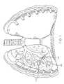
- FIG. 1shows an anterior view of a pair of human lungs and a bronchial tree with a flow control device implanted in a bronchial passageway to bronchially isolate a region of the lung.
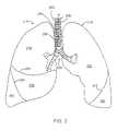
- FIG. 2shows an anterior view of a pair of human lungs and a bronchial tree.
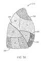
- FIG. 3Ashows a lateral view of the right lung.
- FIG. 3Bshows a lateral view of the left lung.
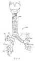
- FIG. 4shows an anterior view of the trachea and a portion of the bronchial tree.
- FIG. 5Ashows a perspective view of a first embodiment of a flow control device that can be implanted in a body passageway.
- FIG. 5Bshows a perspective, cross-sectional view of the flow control device of FIG. 5A .
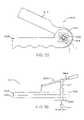
- FIG. 6Ashows a side view of the flow control device of FIG. 5A .
- FIG. 6Bshows a cross-sectional, side view of the flow control device of FIG. 5A .
- FIG. 7Ashows a side, cross-sectional view of a duckbill valve in a closed state.
- FIG. 7Bshows a side, cross-sectional view of a duckbill valve in an open state.
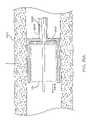
- FIG. 8shows the flow control device of FIGS. 5–6 implanted in a bronchial passageway.
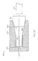
- FIG. 9shows a perspective, cross-sectional view of another embodiment of the flow control device.
- FIG. 10shows a side, cross-sectional view of the flow control device of FIG. 9 .
- FIG. 11shows a front, plan view of the flow control device of FIG. 9 .
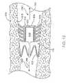
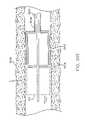
- FIG. 12shows the flow control device of FIG. 9 implanted in a bronchial passageway.
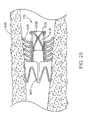
- FIG. 13shows the flow control device of FIG. 9 implanted in a bronchial passageway and dilated by a dilation device comprised of a tube.
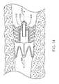
- FIG. 14shows the flow control device of FIG. 9 implanted in a bronchial passageway and dilated by a dilation device comprised of a tube with a one-way valve.
- FIG. 15shows the flow control device of FIG. 9 implanted in a bronchial passageway and dilated by a dilation device comprised of a tube with a one way valve, wherein the tube is attached to a removal tether.
- FIG. 16shows the flow control device of FIG. 9 implanted in a bronchial passageway and dilated by a dilation device comprised of a tube, which is fluidly coupled to a catheter.
- FIG. 17shows the flow control device of FIG. 9 implanted in a bronchial passageway and dilated by a dilation device comprised of a catheter.
- FIG. 18shows another embodiment of a flow control device implanted in a bronchial passageway.
- FIG. 19shows a perspective view of another embodiment of a flow control device.
- FIG. 20shows a side view of the flow control device of FIG. 19 .
- FIG. 21shows a cross-sectional view of the flow control device of FIG. 20 cut along the line 21 — 21 of FIG. 20 .
- FIG. 22shows another embodiment of a flow control device.
- FIG. 23shows a cross-sectional view of the flow control device of FIG. 22 .
- FIG. 24shows a perspective view of another embodiment of a flow control device.
- FIG. 25shows another embodiment of a flow control device implanted in a bronchial passageway.
- FIG. 26shows another embodiment of a flow control device implanted in a bronchial passageway.
- FIG. 27shows the flow control device of FIG. 26 implanted in a bronchial passageway and dilated by a dilation device.
- FIG. 28shows another embodiment of a flow control device implanted in a bronchial passageway.
- FIG. 29shows another embodiment of a flow control device implanted in a bronchial passageway that has an internal, sealed chamber.
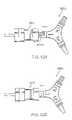
- FIG. 30shows another embodiment of a flow control device implanted in a bronchial passageway, the flow control device having a pair of internal lumens for allowing controlled, two-way fluid flow.
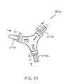
- FIG. 31shows another embodiment of a flow control device implanted in a bronchial passageway, the flow control device having a pair of flap valves for allowing controlled, two-way fluid flow.
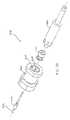
- FIG. 32shows a delivery system for delivering a flow control device to a target location in a body passageway.
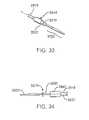
- FIG. 33shows a perspective view of a distal region of a delivery catheter of the delivery system.
- FIG. 34shows a plan, side view of the distal region of the delivery catheter.
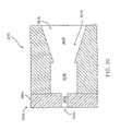
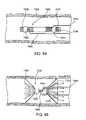
- FIG. 35Ashows a cross-sectional view of a housing of the delivery catheter, the housing containing a flow control device.
- FIG. 35Bshows a cross-sectional view of the housing containing a flow control device that has a distal end that protrudes from the housing.
- FIG. 36Ashows the delivery catheter housing containing a flow control device and implanted at a location L of a bronchial passageway.
- FIG. 36Bshows the delivery catheter deploying the flow control device at the location L of the bronchial passageway.
- FIG. 37shows the delivery catheter deploying the flow control device distally of the location L of the bronchial passageway.
- FIG. 38is a perspective view of a loader system for loading the flow control device onto a delivery catheter.
- FIG. 39shows a cross-sectional side view of a loader device of the loader system.
- FIG. 40shows a perspective view of a pusher device of the loader system.
- FIG. 41shows the loader system readied for loading the flow control device into the housing of the delivery catheter.
- FIG. 42shows the loader system being used to compress the flow control device during loading of the flow control device into the housing of the delivery catheter.
- FIG. 43shows the loader system being used to compress the flow control device during insertion of the flow control device into the housing of the delivery catheter.
- FIG. 44shows the loader system with the flow control device fully loaded into the housing of the delivery catheter.
- FIG. 45shows an exploded, perspective rear view of the loader device of the loader system.
- FIG. 46shows a plan, rear view of the loader device of the loader system with a delivery door in a closed position.
- FIG. 47shows a plan, rear view of the loader device of the loader system with a delivery door in an open position.
- FIG. 48Ashows a perspective, rear view of the loader device of the loader system with the delivery door in an open position and the catheter housing inserted into the loader device.
- FIG. 48Bshows a perspective, rear view of the loader device of the loader system with the delivery door in a closed position and the catheter housing mated with the loader device.
- FIG. 49shows a perspective view of a loading tube of the loader system.
- FIG. 50Ashows the loading tube being used to initially insert the flow control device into the loader device.
- FIG. 50Bshows the loading tube being used to initially insert the flow control device into the loader device.
- FIG. 51shows another embodiment of a pusher device.
- FIG. 52Ashows the pusher device of FIG. 51 initially inserted into the loader device.
- FIG. 52Bshows the pusher device of FIG. 51 fully inserted into the loader device.
- FIG. 53shows an exploded, perspective another embodiment of the loader system.
- FIG. 54shows an exploded, perspective another embodiment of the loader system with the pusher device inserted into the loader device.
- FIG. 55shows a front, plan view of another embodiment of a loader device.
- FIG. 56shows a side, plan view of the loader device of FIG. 55 .
- FIG. 57shows a front, plan view of the loader device of FIG. 55 in a closed state.
- FIG. 58shows a side, plan view of the loader device of FIG. 55 .
- FIG. 59shows a perspective view of a flow control device having a segmented valve/seal component.
- FIG. 60is a front plan view of the valve/seal component of the flow control device depicted in FIG. 59 .
- FIG. 60Bshows a perspective view of a flow control device having a segmented valve/seal component and shows enlarged views of two embodiments of foldable sections.
- FIG. 61is a side view of the flow control device depicted in FIG. 59 .
- FIG. 62is a side view of the flow control device depicted in FIG. 59 , wherein the flow control device is partially deployed.
- FIG. 63is a side view of the flow control device depicted in FIG. 59 , wherein the flow control device is fully retracted.
- FIG. 64is a side view of the flow control device depicted in FIG. 59 placed within a bronchial lumen.
- FIG. 65is a side view of the flow control device depicted in FIG. 64 fully deployed.
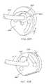
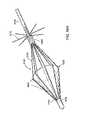
- FIG. 66Ashows a perspective view of an umbrella style flow control device according to one embodiment.
- FIG. 66Bshows a perspective view of the flow control device of FIG. 66 in a contracted state.
- FIG. 66Cshows an enlarged view of one embodiment of a retention strut.
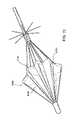
- FIG. 67shows a perspective view of an umbrella style flow control device with a retention spring according to another embodiment.
- FIG. 68shows a perspective view of an umbrella style flow control device with curved struts according to another embodiment.
- FIG. 69shows a perspective view of an umbrella style flow control device with pleated membrane according to another embodiment.
- FIG. 70shows a perspective view of an umbrella style flow control device with bended struts according to another embodiment.
- FIG. 71shows a bronchoscope deployed within a bronchial tree of a patient.
- FIG. 72shows a guidewire deployed within a bronchial tree of a patient.
- FIG. 73shows a delivery catheter deployed within a bronchial tree of a patient over a guidewire.
- FIG. 74shows a perspective view of a delivery catheter having an asymmetric, distal tip.
- FIG. 75shows a perspective view of another embodiment of a delivery catheter having an asymmetric, distal tip.
- FIG. 76shows a delivery catheter having a distal curve and an asymmetric distal tip.
- An identified region of the lung(referred to herein as the “targeted lung region”) is targeted for treatment, such as to modify the air flow to the targeted lung region or to achieve volume reduction or collapse of the targeted lung region.
- the targeted lung regionis then bronchially isolated to regulate airflow into and/or out of the targeted lung region through one or more bronchial passageways that feed air to the targeted lung region. As shown in FIG.
- the bronchial isolation of the targeted lung regionis accomplished by implanting a flow control device 110 into a bronchial passageway 115 that feeds air to a targeted lung region 120 .
- the flow control device 110regulates airflow through the bronchial passageway 115 in which the flow control device 110 is implanted, as described in more detail below.
- the flow control device 110can be implanted into the bronchial passageway using a delivery system, such as the delivery system catheter described herein.
- lung regionrefers to a defined division or portion of a lung.
- lung regionsare described herein with reference to human lungs, wherein some exemplary lung regions include lung lobes and lung segments.
- lung regionas used herein can refer to a lung lobe or a lung segment.
- Such lung regionsconform to portions of the lungs that are known to those skilled in the art.
- lung regiondoes necessarily refer to a lung lobe or a lung segment, but can also refer to some other defined division or portion of a human or non-human lung.
- FIG. 2shows an anterior view of a pair of human lungs 210 , 215 and a bronchial tree 220 that provides a fluid pathway into and out of the lungs 210 , 215 from a trachea 225 , as will be known to those skilled in the art.
- the term “fluid”can refer to a gas, a liquid, or a combination of gas(es) and liquid(s).
- FIG. 2shows only a portion of the bronchial tree 220 , which is described in more detail below with reference to FIG. 4 .
- FIG. 2shows a path 202 that travels through the trachea 225 and through a bronchial passageway into a location in the right lung 210 .
- proximal directionrefers to the direction along such a path 202 that points toward the patient's mouth or nose and away from the patient's lungs.
- the proximal directionis generally the same as the expiration direction when the patient breathes.
- the arrow 204 in FIG. 2points in the proximal direction.
- the term “distal direction”refers to the direction along such a path 202 that points toward the patient's lung and away from the mouth or nose.
- the distal directionis generally the same as the inhalation direction when the patient breathes.
- the arrow 206 in FIG. 2points in the distal direction.
- the lungsinclude a right lung 210 and a left lung 215 .
- the right lung 210includes lung regions comprised of three lobes, including a right upper lobe 230 , a right middle lobe 235 , and a right lower lobe 240 .
- the lobes 230 , 235 , 240are separated by two interlobar fissures, including a right oblique fissure 226 and a right transverse fissure 228 .
- the right oblique fissure 226separates the right lower lobe 240 from the right upper lobe 230 and from the right middle lobe 235 .
- the right transverse fissure 228separates the right upper lobe 230 from the right middle lobe 135 .
- the left lung 215includes lung regions comprised of two lobes, including the left upper lobe 250 and the left lower lobe 255 .
- An interlobar fissure comprised of a left oblique fissure 245 of the left lung 215separates the left upper lobe 250 from the left lower lobe 255 .
- the lobes 230 , 235 , 240 , 250 , 255are directly supplied air via respective lobar bronchi, as described in detail below.
- FIG. 3Ais a lateral view of the right lung 210 .
- the right lung 210is subdivided into lung regions comprised of a plurality of bronchopulmonary segments. Each bronchopulmonary segment is directly supplied air by a corresponding segmental tertiary bronchus, as described below.
- the bronchopulmonary segments of the right lung 210include a right apical segment 310 , a right posterior segment 320 , and a right anterior segment 330 , all of which are disposed in the right upper lobe 230 .
- the right lung bronchopulmonary segmentsfurther include a right lateral segment 340 and a right medial segment 350 , which are disposed in the right middle lobe 235 .
- the right lower lobe 240includes bronchopulmonary segments comprised of a right superior segment 360 , a right medial basal segment (which cannot be seen from the lateral view and is not shown in FIG. 3A ), a right anterior basal segment 380 , a right lateral basal segment 390 , and a right posterior basal segment 395 .
- FIG. 3Bshows a lateral view of the left lung 215 , which is subdivided into lung regions comprised of a plurality of bronchopulmonary segments.
- the bronchopulmonary segmentsinclude a left apical segment 410 , a left posterior segment 420 , a left anterior segment 430 , a left superior segment 440 , and a left inferior segment 450 , which are disposed in the left lung upper lobe 250 .
- the lower lobe 255 of the left lung 215includes bronchopulmonary segments comprised of a left superior segment 460 , a left medial basal segment (which cannot be seen from the lateral view and is not shown in FIG. 3B ), a left anterior basal segment 480 , a left lateral basal segment 490 , and a left posterior basal segment 495 .
- FIG. 4shows an anterior view of the trachea 225 and a portion of the bronchial tree 220 , which includes a network of bronchial passageways, as described below.
- the trachea 225divides at a distal end into two bronchial passageways comprised of primary bronchi, including a right primary bronchus 510 that provides direct air flow to the right lung 210 , and a left primary bronchus 515 that provides direct air flow to the left lung 215 .
- Each primary bronchus 510 , 515divides into a next generation of bronchial passageways comprised of a plurality of lobar bronchi.
- the right primary bronchus 510divides into a right upper lobar bronchus 517 , a right middle lobar bronchus 520 , and a right lower lobar bronchus 522 .
- the left primary bronchus 515divides into a left upper lobar bronchus 525 and a left lower lobar bronchus 530 .
- Each lobar bronchus, 517 , 520 , 522 , 525 , 530directly feeds fluid to a respective lung lobe, as indicated by the respective names of the lobar bronchi.
- the lobar bronchieach divide into yet another generation of bronchial passageways comprised of segmental bronchi, which provide air flow to the bronchopulmonary segments discussed above.
- a bronchial passagewaydefines an internal lumen through which fluid can flow to and from a lung.
- the diameter of the internal lumen for a specific bronchial passagewaycan vary based on the bronchial passageway's location in the bronchial tree (such as whether the bronchial passageway is a lobar bronchus or a segmental bronchus) and can also vary from patient to patient.
- the internal diameter of a bronchial passagewayis generally in the range of 3 millimeters (mm) to 10 mm, although the internal diameter of a bronchial passageway can be outside of this range.
- a bronchial passagewaycan have an internal diameter of well below 1 mm at locations deep within the lung.
- the flow control device 110can be implanted in a bronchial passageway to regulate the flow of fluid through the bronchial passageway.
- the flow control device 110anchors within the bronchial passageway in a sealing fashion such that fluid in the bronchial passageway must pass through the flow control device in order to travel past the location where the flow control device is located.
- the flow control device 110has fluid flow regulation characteristics that can be varied based upon the design of the flow control device.
- the flow control device 110can be configured to either permit fluid flow in two directions (i.e., proximal and distal directions), permit fluid flow in only one direction (proximal or distal direction), completely restrict fluid flow in any direction through the flow control device, or any combination of the above.
- the flow control devicecan be configured such that when fluid flow is permitted, it is only permitted above a certain pressure, referred to as the cracking pressure.
- the flow control device 110can also be configured such that a dilation device can be manually inserted into the flow control device 110 to vary the flow properties of the flow control device 110 .
- FIGS. 5–6show a first embodiment of a flow control device 110 .
- FIG. 5Ashows a perspective view of the device 110
- FIG. 5Bshows a perspective, cross-sectional view of the device 110
- FIG. 6Ashows a plan, side view of the device 110
- FIG. 6Bshows a cross-sectional, plan, side view of the device 110 .
- the flow control device 110extends generally along a central axis 605 (shown in FIGS. 5B and 6B ) and has a proximal end 602 and a distal end 604 .
- the flow control device 110includes a main body that defines an interior lumen 610 through which fluid can flow along a flow path that generally conforms to the central axis 605 .
- the flow of fluid through the interior lumen 610is controlled by a valve member 612 that is disposed at a location along the interior lumen such that fluid must flow through the valve member 612 in order to flow through the interior lumen 610 , as described more fully below. It should be appreciated that the valve member 612 could be positioned at various locations along the interior lumen 610 .
- the valve member 612can be made of a biocompatible material, such as a biocompatible polymer, such as silicone.
- the size of the valve member 612can vary based on a variety of factors, such as the desired cracking pressure of the valve member 612 .
- the flow control device 110has a general outer shape and contour that permits the flow control device 110 to fit entirely within a body passageway, such as within a bronchial passageway.
- the flow control device 110has a generally circular shape (when viewed longitudinally along the axis 605 ) that will facilitate insertion of the flow control device into a bronchial passageway.
- a circular shapegenerally provides a good fit with a bronchial passageway, although it should be appreciated that the flow control device 110 can have other cross-sectional shapes that enable the device 110 to be inserted into a bronchial passageway.
- the flow control device 110includes an outer seal member 615 that provides a seal with the internal walls of a body passageway when the flow control device is implanted into the body passageway.
- the seal member 615is manufactured of a deformable material, such as silicone or a deformable elastomer.
- the flow control device 110also includes an anchor member 618 that functions to anchor the flow control device 110 within a body passageway. The configurations of the seal member 615 and the anchor member 618 can vary, as described below.
- the seal member 615is generally located on an outer periphery of the flow control device 110 .
- the seal memberincludes a series of radially-extending, circular flanges 620 that surround the outer circumference of the flow control device 110 .
- the flanges 620can be manufactured of silicone or other deformable elastomer.
- the radial length of each flange 620varies moving along the longitudinal length (as defined by the longitudinal axis 605 in FIG. 6B ) of the flow control device 110 .
- the radial lengthcould be equal for all of the flanges 620 or that the radial length of each flange could vary in some other manner.
- the flanges 620can alternate between larger and shorter radial lengths moving along the longitudinal length of the flow control device, or the flanges can vary in a random fashion.
- the flanges 620could be oriented at a variety of angles relative to the longitudinal axis 605 of the flow control device.
- the radial length of a single flangecould vary so that the circumference of the flange is sinusoidal about the center of the flange.
- the seal member 615includes a cuff 622 .
- the cuff 622comprises a region of the seal member 615 that overlaps on itself so as to form a cavity 623 within the cuff 622 .
- the cavity 623can be used to retain the anchor member 618 to the seal member 615 of the flow control device 110 .
- the cuff 622can function in combination with the flanges 620 to seal the flow control device to the internal walls of a bronchial lumen when the flow control device is implanted in a bronchial lumen, as described below.
- the cuff 622can be formed in a variety of manners, such as by folding a portion of the seal member 615 over itself, or by molding the seal member 615 to form the cuff 622 .
- the anchor member 618functions to anchor the flow control device 110 in place when the flow control device is implanted within a body passageway, such as within a bronchial passageway.
- the anchor member 618has a structure that can contract and expand in size (in a radial direction and/or in a longitudinal direction) so that the anchor member can expand to grip the interior walls of a body passageway in which the flow control device is positioned.
- the anchor member 618comprises an annular frame 625 that surrounds the flow control device 110 .
- the frame 625is formed by a plurality of struts that define an interior envelope sized to surround the interior lumen 610 .
- the struts of the frame 625form curved, proximal ends 629 that can be slightly flared outward with respect to the longitudinal axis 605 .
- the curved, proximal ends 629can anchor into the bronchial walls and prevent migration of the flow control device in a proximal direction.
- the frame 625can also have flared, distal prongs 627 that can anchor into the bronchial walls and to prevent the device 110 from migrating in a distal direction when the flow control device 110 is placed in a bronchial lumen.
- the frame 625can be formed from a super-elastic material, such as Nickel Titanium (also known as Nitinol), such as by cutting the frame out of a tube of Nitinol or by forming the frame out of Nitinol wire.
- a super-elastic materialsuch as Nickel Titanium (also known as Nitinol)
- NitinolNickel Titanium
- the super-elastic properties of Nitinolcan result in the frame exerting a radial force against the interior walls of a bronchial passageway sufficient to anchor the flow control device 110 in place.
- the strutsare arranged so that the frame 625 can expand and contract in a manner that is entirely or substantially independent of the rest of the flow control device 110 , including the valve member 612 , as described more fully below.
- the frame 625is attached to the flow control device 110 inside the cavity 623 of the cuff 622 . That is, at least a portion of the frame 625 is positioned inside the cavity 623 .
- the frame 625is not necessarily fixedly attached to the cavity. Rather, a portion of the frame 625 is positioned within the cavity 623 so that the frame 625 can freely move within the cavity, but cannot be released from the cavity.
- an attachment meanscan be used to attach the opposing pieces of the cuff 622 to one another so that the frame 625 cannot fall out of the cavity 623 .
- the attachment meanscomprises an adhesive, such as silicone adhesive, that is placed inside the cavity 623 and that adheres the opposing pieces of the cuff 622 to one another.
- rivetsare used to attach the opposing pieces of the cuff.
- different attachment meanscould be used to secure the frame 625 to the seal member 615 .
- the frame 625is not necessarily bonded to the seal member 615 .
- the frame 625can be integrally formed with the valve protector member 637 , described below.
- valve member 612regulates the flow of fluid through the interior lumen 610 of the flow control device 110 .
- the valve member 612can be configured to permit fluid to flow in only one-direction through the interior lumen 610 , to permit regulated flow in two-directions through the interior lumen 610 , or to prevent fluid flow in either direction.
- the valve member 612is positioned at a location along the interior lumen 610 so that fluid must travel through the valve member 612 in order to flow through the interior lumen 610 .
- the valve member 612can be any type of fluid valve, and preferably is a valve that enables the cracking pressures described herein.
- the valve member 612can have a smaller diameter than the frame 625 so that compression or deformation of the frame 625 in both a radial and axial direction will have little or no impact on the structure of the valve member 612 .
- the valve member 612comprises a duckbill valve that includes two flaps 631 (shown in FIGS. 5B and 6B ) that are oriented at an angle with respect to one another and that can open and close with respect to one another so as to form an opening at a lip 801 ( FIG. 6B ) where the flaps 631 touch one another.
- FIG. 7Ashows a schematic side-view of the duckbill valve in a closed state, wherein the flaps 631 touch one another at the lip 801 .
- the duckbill valveprevents fluid flow in a first direction, which is represented by the arrow A in FIG. 7A .
- the flaps 631separate from one another to form an opening between the flaps 631 that permits flow in the second direction, as shown in FIG. 7B .
- valve member 612is concentrically contained within the seal member 615 .
- at least a portion of the valve member 612is optionally surrounded by a rigid or semi-rigid valve protector member 637 (shown in FIGS. 5B and 6B ), which is a tubular member or annular wall that is contained inside the seal member 615 .
- the valve protectorcan comprise a coil of wire or a ring of wire that provides some level of structural support to the flow control device.
- the valve protector 637can be concentrically located within the seal member 615 .
- the valve member 612can be completely molded within the seal member 615 such that the material of the seal member 615 completely surrounds the valve protector.
- the valve protector member 637is optional, although when present, the valve protector member 637 protects the valve member 612 from damage and can maintain the shape of the flow control device 110 against compression and constriction to a certain extent.
- the valve protection member 637can also support and stiffen the flanges 620 .
- the valve protector member 637can be manufactured of a rigid, biocompatible material, such as, for example, nickel titanium, steel, plastic resin, and the like.
- the valve protector member 637has two or more windows 639 comprising holes that extend through the valve protector member, as shown in FIG. 6B .
- the windows 639can provide a location where a removal device, such as graspers or forceps, can be inserted in order to facilitate removal of the flow control device 110 from a bronchial passageway.
- the valve protector member 637can be formed out of a solid tube of a super-elastic material such as Nitinol.
- the valve protector member 637is compressible to a smaller diameter for loading into a delivery catheter.
- the compressibilitycan be achieved by forming the valve protector member 637 out of a series of struts or by including some open spaces in the valve protector member 637 .
- the super-elastic characteristics of Nitinolwould allow the valve protector member 637 to be compressed during deployment, yet still allow it to expand once deployed.
- the seal 615 and/or the frame 625can contract or expand in size, particularly in a radial direction.
- the default stateis an expanded size, such that the flow control device 110 will have a maximum diameter (which is defined by either the seal 615 or the frame 625 ) when the flow control device 110 is in the default state.
- the flow control device 110can be radially contracted in size during insertion into a bronchial passageway, so that once the flow control device 110 is inserted into the passageway, it expands within the passageway.
- valve member 612 and frame 625are independently enlargeable and contractible.
- the frame 625can be enlargeable and contractible, while the valve member 612 is not enlargeable and contractible.
- the independent collapsibility of the valve member 612 and frame 625facilitate deployment and operation of the flow control device 110 .
- the flow control device 110can be compressed from a default, enlarged state and implanted in a desired location within a bronchial passageway. Once implanted, the flow control device 110 automatically re-expands to anchor within the location of the bronchial passageway.
- the independent compression of the frame and valve memberreduces the likelihood of damage to the flow control device 110 during deployment.
- valvecan be substantially immune to the effects of compression of the frame 625 .
- the diameter of the frame 625may collapse as much as 80% without affecting the valve member 612 so that the valve member 612 will still operate normally.
- the flow control device 110does not have to be precisely sized for the lumen it is to be placed within. This affords medical providers with the option of buying smaller volumes of the flow control device 110 and being able to provide the same level and scope of coverage for all patients.
- the dimensions of the flow control device 110can vary based upon the bronchial passageway in which the flow control device 110 is configured to be implanted. As mentioned, the valve member does not have to be precisely sized for the bronchial passageway it is to be placed within. Generally, the diameter D (shown in FIG. 6A ) of the flow control device 110 in the uncompressed state is larger than the inner diameter of the bronchial passageway in which the flow control device 110 will be placed. This will permit the flow control device 110 to be compressed prior to insertion in the bronchial passageway and then expand upon insertion in the bronchial passageway, which will provide for a secure fit between the flow control device 110 and the bronchial passageway.
- FIG. 8shows the flow control device 110 of FIGS. 5–6 implanted within a bronchial passageway 910 having interior walls 915 that define a lumen of the bronchial passageway 910 .
- fluidssuch as air
- FIG. 8shows the flow control device 110 of FIGS. 5–6 implanted within a bronchial passageway 910 having interior walls 915 that define a lumen of the bronchial passageway 910 .
- fluidssuch as air
- the flow control device 110is implanted such that one or more of the flanges 620 contact the interior walls 915 to provide a seal that prevents fluid from flowing between the interior walls 915 and the flanges 620 .
- the cuff 622can also provide a seal with the bronchial passageway. At least a portion of the outermost surface of the cuff 622 sealingly engages the surface of the interior walls 915 .
- the flanges 620 and the cuff 622both provide a seal between the interior walls 915 of the bronchial passageway 910 and the flow control device 110 .
- fluidmust flow through the interior lumen 610 of the flow control device 110 in order to flow from a proximal side 1301 of the flow control device 110 to a distal side 1302 or vice-versa. That is, the flanges 620 and cuff 620 form a seal with the interior wall 915 to prevent fluid from flowing around the periphery of the flow control device 110 , thereby forcing fluid flow to occur through the internal lumen of the flow control device 110 , and specifically through the valve member 612 .
- valve member 612is oriented such that it will permit regulated fluid flow in the proximal direction 204 , but prevent fluid in a distal direction 206 through the flow control device 110 .
- the valve member 612will only permit fluid flow therethrough when the fluid reaches a predetermined cracking pressure, as described below.
- Other types of valve members, or additional valve members,could be used to permit fluid flow in both directions or to prevent fluid flow in either direction.
- the frame 625grips the interior wall 915 and presses against the wall 915 with a pressure sufficient to retain the flow control device 110 in a fixed position relative to the bronchial passageway.
- the prongs 627are positioned such that they lodge against the interior walls 915 and prevent the flow control device 110 from migrating in a distal direction 206 .
- the curved, proximal ends 629 of the frame 625can lodge against the interior walls 915 and prevent migration of the flow control device 110 in a proximal direction 204 .
- the frame 625When the flow control device 110 is properly implanted, the frame 625 does not necessarily return to its original expanded state after being implanted, but may be deformed and inserted such that one side is collapsed, or deformed relative to its pre-insertion shape.
- the frame 625preferably has sufficient outward radial force to maintain the flow control device's position in the bronchial passageway. Due to the substantially independent deformation of the frame 625 , even if the frame 625 is implanted in a deformed state, the seal member 615 can still maintain a true and complete contact with the walls of the bronchial passageway.
- the frame 625expands to grip the bronchial wall when the flow control device 110 is implanted in the bronchial passageway.
- the frame 625can be in at least two states, including an insertion (compressed) state and an anchoring (expanded or uncompressed) state.
- the frame 625In the insertion state, the frame 625 has a smaller diameter than in the anchoring state.
- Various mechanismscan be employed to achieve the two states.
- the frame 625is manufactured of a malleable material.
- the frame 625can be manually expanded to the anchoring state, such as by inserting an inflatable balloon inside the frame once the flow control device 110 is implanted in the bronchial passageway, and then inflating the balloon to expand the frame beyond the material's yield point into an interfering engagement with the wall of the bronchial passageway.
- the insertion statecan be achieved through a preconstraint of the frame 625 within the elastic range of the frame material. Once positioned in the bronchial passageway, the frame 625 can be released to expand into an anchoring state. Constraining tubes or pull wires may achieve the initial insertion state.
- Another mechanism that can be used to achieve both the insertion and the anchor states of the frame 625is the heat recovery of materials available with alloys, such as certain nickel titanium alloys, including Nitinol.
- the transition temperature of the frame 625could be below body temperature. Under such a circumstance, a cool frame 625 can be positioned and allowed to attain ambient temperature. The unrecovered state of the frame 625 would be in an insertion position with the frame 625 having a smaller diameter. Upon recovery of the frame material, the frame 625 would expand, such as when the frame achieves a temperature within the bronchial passageway.
- Another use of this materialmay be through a heating of the device above body temperature with a recovery temperature zone above that of normal body temperature but below a temperature which may cause burning. The device might be heated electrically or through the modulation of a field.
- the outer diameter of the seal member 615 of the flow control device 110(in an uncompressed state) is in the range of approximately 0.20 inches to 0.42 inches at the flanges 620 or at the cuff 622 .
- the frame 625has an outer diameter (in an uncompressed state) in the range of approximately 0.24 to 0.48 inches.
- the flow control device 110has an overall length from the proximal end 602 to the distal end 604 of approximately 0.35 inches to 0.52 inches. It should be appreciated that the aforementioned dimensions are merely exemplary and that the dimensions of the flow control device 110 can vary based upon the bronchial passageway in which it will be implanted.
- FIGS. 9–11show another embodiment of the flow control device 110 .
- FIG. 9shows a perspective, cross-sectional view
- FIG. 10shows a side, cross-sectional view
- FIG. 11shows a front, plan view of the other embodiment of the flow control device 110 .
- This embodiment of the flow control devicehas an anchor member 618 comprising a frame 625 that is disposed in a spaced relationship from the rest of the flow control device 110 . That is, the frame 625 is distally-spaced from the seal member 615 and the internal lumen 610 .
- the flow control device 110extends generally along a central axis 605 (shown in FIGS.
- FIG. 9shows the valve member 612 located at an end of the interior lumen 610 , although it should be appreciated that the valve member 612 could be positioned at various locations along the interior lumen 610 .
- the flow control device 110has a generally circular shape (when viewed longitudinally) that will facilitate insertion of the flow control device into a bronchial passageway, although it should be appreciated that the flow control device 110 can have other cross-sectional shapes that enable the device to be inserted into a bronchial passageway.
- the seal member 615is located on an outer periphery of the flow control device 110 .
- the seal memberincludes a series of radially-extending, circular flanges 620 that surround the entire outer circumference of the flow control device 110 .
- the anchor member 618is shown located on a distal end of the flow control device 110 , although the anchor member 618 can be located at various locations along the flow control device 110 .
- the frame 625is attached to the flow control device 110 by one or more attachment struts 626 although the frame 625 could also be attached in other manners.
- the valve member 612comprises a septum 630 located at a proximal end of the interior lumen 610 .
- the septum 630occludes fluid from flowing through the interior lumen 610 so that the flow control device 110 shown in FIGS. 9–11 can function as an occluder that prevents flow in either direction.
- the septum 630can be pierced by a dilator device (described below) via a slit 635 in the septum 630 , in order to permit fluid to flow through the interior lumen 610 .
- the septum 630is made from a deformable elastic material.
- the dilator devicecould comprise a wide variety of devices that function to dilate the slit 635 in the septum 630 and thereby provide a passageway across the flow device 110 through which fluid can flow in one or two directions, depending on the design of the dilator device.
- the dilator devicescould comprise, for example:
- dilator devices described abovegenerally fall into two categories, including catheter-type dilation devices and dilation devices comprised of short, tube-like structures.
- flow control device 110can be used with various dilation devices that are not limited to those mentioned above.
- FIGS. 12 and 13show the flow control device 110 of FIGS. 9–11 implanted within a bronchial passageway 910 having interior walls 915 that define a lumen of the bronchial passageway 910 .
- the flow control device 110is implanted such that one or more of the flanges 620 contact the interior walls 915 to provide a seal that prevents fluid from flowing between the interior walls 915 and the flanges 620 .
- fluidmust flow through the interior lumen 610 of the flow control device 110 in order to flow from a proximal side 1301 of the flow control device 110 to a distal side 1302 or vice-versa.
- the relative locations of the flanges 620 and the frame 625 along the longitudinal axis of the flow control devicecan be changed.
- the flanges 620could be located on the distal side of the flow control device 110 rather than on the proximal side, and the frame 625 can be located on the proximal side rather than the distal side.
- the flow control device 110could also be positioned in a reverse orientation in the bronchial passageway than that shown in FIG. 12 .
- the orientation of the valve member 612could be arranged to permit flow in a desired direction, such as in a proximal direction 204 (to allow air flow out of a lung region), a distal direction 206 (to allow air flow into a lung region), or in both directions.
- the orientation of the flanges 620can also be changed based upon how the flow control device 110 is to be implanted in the bronchial passageway.
- the frame 625grips the interior wall 915 and presses against the wall 915 with a pressure sufficient to retain the flow control device 110 in a fixed position.
- the flow control device 110obstructs the bronchial passageway 910 to prevent fluid from flowing in either direction through the bronchial passageway 910 .
- the septum 630can be sufficiently rigid so that the slit 635 does not open when subjected to expiration and inhalation pressures.
- other embodiments of the flow control device 110can be used to provide regulated fluid flow through the bronchial passageway 910 in a distal direction, a proximal direction, or in both the distal and proximal directions.
- the septum 630can be mechanically pierced through the slit 635 , such as by using a dilator device comprised of a tube 1010 that dilates the slit 635 .
- the septum 630can have no slit 635 and the tube 1010 can be used to pierce through the septum 630 .
- the septum 630preferably seals around the outer surface of the tube 1010 in order to prevent fluid flow in the space between the septum 630 and the tube 1010 .
- the tube 1010is hollow and has an internal lumen such that the tube 1010 provides an unobstructed fluid flow passageway between a region of the bronchial passageway 910 distal of the flow control device 110 and a region of the bronchial passageway proximal of the flow control device 110 .
- Various dilator devicescan be inserted through the flow control device 110 to provide various flow characteristics to the flow control device, as well as to provide access to the region of the bronchial passageway located distal of the flow control device 110 .
- the dilation devicecan be pre-loaded into the flow control device 110 prior to deploying the flow control device 110 to the bronchial passageway.
- the flow control device 110can be implanted into the bronchial passageway without the dilation device and the dilation device inserted into the flow control device 110 after implant of the flow control device 110 .
- FIG. 14shows another embodiment wherein the dilator device comprises a tube section 1110 that includes a one-way valve 1120 mounted thereon.
- the one-way valve 1120can be any type of valve that permits fluid flow in a first direction but prevents fluid flow in a second direction opposite to the first direction.
- the one-way valve 1120can comprise a duckbill valve of the type known to those skilled in the art.
- the one-way valve 1120can be positioned such that it allows fluid flow in an exhalation direction (i.e., proximal direction) 204 but prohibits fluid flow in an inhalation direction (i.e., distal direction) 206 .
- FIG. 15shows the flow control device 110 with the septum 630 dilated by a tube section 1110 that includes a one-way valve 1120 mounted thereon.
- the tube section 1110has an attachment structure, such as a flange 1210 .
- a remote actuator, such as a tether 1215is attached at a proximal end to the attachment structure 1210 of the tube section 1110 .
- the tether 1215can be formed of a variety of bio-compatible materials, such as any well-known suture material.
- the tether 1215extends in a proximal direction through the bronchial passageway 910 and through the trachea (shown in FIG.
- the tethercan be pulled outwardly, which will also cause the attached tube structure 1110 to be pulled outwardly from the septum 630 by virtue of the tether's attachment to the tube attachment structure 1210 .
- the absence of the tube structure 110would then cause the septum 630 to re-seal so that the flow control device 110 again occludes fluid flow through the bronchial lumen 910 .
- FIG. 16shows the flow control device 110 implanted in the bronchial lumen 910 , with the septum 630 dilated by a tube section 1110 that includes a one-way valve 1120 mounted thereon.
- the one-way valve 1120fluidly communicates with the internal lumen of a catheter 1310 at a distal end of the catheter 1310 .
- the catheter 1310extends in a proximal direction through the bronchial passageway 910 and through the trachea (shown in FIG. 2 ) so that a proximal end of the catheter 1310 protrudes through the mouth or nose of the patient.
- the catheter 1310thereby provides an airflow passageway for fluid flowing through the one-way valve 1120 .
- the catheter 1310 in combination with the one-way valve 1120 and the flow control device 110provide a regulated fluid access to the bronchial passageway 910 at a location distal of the flow control device 110 .
- the catheter 1310can thus be used to aspirate fluid from a location distal of the flow control device 110 by applying a suction to the proximal end of the catheter 1310 , which suction is transferred to the distal region of the bronchial passageway through the internal lumen of the catheter 1310 , the tube section 1110 , and the flow control device 110 .
- the catheteroptionally has one or more vent holes 1320 at a location proximal of the one-way valve 1120 .
- the vent holes 1320permit fluid to flow from the internal lumen of the catheter 1310 into the bronchial passageway proximal of the flow control device 110 .
- FIG. 17shows the flow control device 110 mounted within the bronchial passageway 910 , with the slit of the septum 630 dilated by a catheter 1310 .
- a distal end of the catheter 1310is located distally of the septum 630 .
- the catheter 1310extends in a proximal direction through the bronchial passageway 910 and through the trachea (shown in FIG. 2 ) so that a proximal end of the catheter 1310 protrudes through the mouth or nose of the patient.
- the catheter 1310provides an airflow passageway across the flow control device 110 .
- the catheter 1310provides unobstructed fluid access to the bronchial passageway 910 at a location distal of the flow control device 110 .
- the catheter 1310can thus be used to aspirate fluid from a location distal of the flow control device 110 by applying a suction to the proximal end of the catheter 1310 , which suction is transferred to the distal region of the bronchial passageway through the internal lumen of the catheter 1310 .
- the catheter 1310also enables the instillation of therapeutic agents into the distal side of the flow control device, the passing of brachytherapy sources to the distal side of the flow control device, etc, all via the internal lumen of the catheter 1310 .
- FIG. 18shows an alternate embodiment of the flow control device 110 mounted in a bronchial passageway.
- This embodiment of the flow control device 110is identical to that described above with reference to FIGS. 9–11 , with the exception of the configuration of the septum 630 and the slit 635 .
- a distal face of the septumhas a taper 1510 located at the slit 635 .
- the taper 1510functions to reduce the cracking pressure required to open slit 635 so that the cracking pressure of the septum 630 will be lower for flow moving from the distal side 1302 toward the proximal side 1301 of the flow control device 110 , and higher for flow from the proximal side 1301 to the distal side 1302 .
- the cracking pressurecan be made the same in both directions by eliminating the taper 1510 .
- the cracking pressurecan be varied by changing the durometer of the elastomer, by changing the diameter of the valve, by changing the length of the slit 635 , by changing the angle, depth or shape of the taper feature 1510 , or by changing the thickness of the valve feature.
- FIGS. 19–21show another embodiment of the flow control device 110 , which permits fluid flow in a first direction but prevents fluid flow in a second direction opposite the first direction.
- the flow control device 110includes a seal member 615 , a valve member 612 , and an anchor member 618 , as well as an interior lumen 610 formed by an annular wall 608 (shown in FIG. 21 ).
- the annular wall 608can be made from Nitinol, injection molded plastic such as polyetheretherketone (PEEK), or other rigid biocompatible materials.
- the anchor member 618comprises a frame 625 that is formed by a plurality of struts that define an interior envelope.
- the frame 625can contract and expand in a radial and longitudinal direction (relative to the longitudinal axis 1805 shown in FIG. 21 ).
- the struts of the frame 625are arranged so that one or more of the struts form prongs 1605 having edges that can wedge against the interior wall of a body passageway to secure an implanted flow control device against movement within the body passageway.
- the anchor member 618can be manufactured of a shape-memory material, such as nickel titanium or Nitinol.
- the valve member 612comprises a one-way flap valve that permits fluid flow in a first flow direction.
- the flap valveincludes a flap 1610 , which can move between a closed position and an open position (the flap 1610 is shown in an open position in FIGS. 19–21 ). In the closed position, the flap 1610 sits within a seat to block fluid flow through the interior lumen 610 . In the open position, the flap provides an opening into the interior lumen 610 so that fluid can flow through the interior lumen in the first flow direction.
- the seal member 615includes one or more flanges 620 that can seal against the interior wall of a body passageway in which the flow control device 110 is implanted. As shown in FIGS. 21 , the flanges 625 of the seal member 615 surround the annular wall 608 that forms the interior lumen 610 .
- the flap 1610 and the seal member 615can be manufactured of an elastomeric material such as silicone, thermoplastic elastomer, urethane, etc.
- the flap 1610can also be a rigid member that seals against an elastomer surface of the device 110 , or it could be rigid and lined with an elastomer material. If a rigid flap is used, then hinges can be used to attach the flap to the device 110 .
- the seal member 615folds over itself to form an annular cuff 1625 .
- At least a portion of the frame 625is positioned within the cuff and retained therein using retaining members, such as rivets 1630 that extend through holes in the cuff 1625 .
- the rivets 1630can be manufactured of a bio-compatible material, such as silicone adhesive. The rivets 1630 secure the cuff 1625 to the frame 625 so as to allow the frame 625 to expand and contract, but to still firmly capture the frame 625 to the cuff 1625 . As best shown in the section view of FIG.
- the rivets 1630extend between opposed sides of the cuff 1625 to capture but not totally restrain the frame 625 against expansion or contraction. It should be appreciated that other attachment means can be used to attach the frame 625 to the cuff 1625 .
- adhesivecan be used as in the previously-described embodiments.
- rivets 1630may be used in any variety of patterns around the circumference of the cuff 1625 . While the rivets 1630 may be short in length such that there is little play between the folded over region of the cuff 1625 and the portion of the cuff 1625 located within the frame envelope, the rivets 1630 may be lengthened so that there is substantial play between the folded-over portion of the cuff 1625 and the interior region of the cuff 1625 . In this manner, the frame 625 can be crumpled or deformed during deployment, while still allowing sufficient space for the folded-over region of the cuff 1625 to remain in contact with the lumen wall, helping to form a seal about the flow control device 110 .
- the frame envelopewill conform to the lumen internal diameter where the flow control device 110 is implanted. However if there are gaps between the frame envelope and the lumen interior wall, then the cuff 1625 is capable of providing the fluid seal.
- the rivetsare installed onto the flow control device 110 by first sliding the flow control device 110 over a dimpled mandrel. A hole is then drilled through the two walls of the cuff 1625 , and the hole is filled with a glue, such as silicone adhesive, which will dry within the hole to form the rivets.
- a gluesuch as silicone adhesive
- the hole in the mandrelcan have a dimpled shape that forms the inside rivet heads, while the outer heads can be formed by applying excessive adhesive on the outside.
- the assemblyis then cured in an oven and slid off the mandrel.
- the cuff 1625may have a length such that the cuff 1625 folds over the entire length of the frame 625 .
- the cuff 1625is reattached to the proximal end of the polymer valve, such that the frame 625 is completely enclosed by the cuff 1625 , so as the frame 625 is implanted within the bronchial passageway, the loose folds of the polymer skirt can provide a sealing feature.
- FIGS. 22–24show yet another embodiment of a flow control device 110 .
- the flow control device 110 shown in FIGS. 22–24is structurally similar to the flow control device 110 described above with reference to FIGS. 19–21 in that it includes a seal member 615 with a cuff 1625 and flanges 620 .
- the cuff 1625retains an anchor member 618 comprised of a frame 625 .
- the flow control device 110 of FIGS. 22–24also includes a valve member 612 comprised of a one-way duckbill valve 1910 .
- the duckbill valve 1910is configured to prevent fluid flow from a proximal side to the distal side of the flow control device 110 , and to allow flow at a controlled cracking pressure from the distal side to the proximal side through a slit 1920 (shown in FIG. 24 ) in the valve 1910 .
- the cracking pressure of the duckbill valve 1910can be adjusted by changing the thickness of the material used to manufactured the valve 1910 , the durometer of the material, the angle of the duckbill valve, etc.
- the duckbill valvecan be manufactured a deformable elastomer material, such as silicone.
- the flow control devicehas valve dilation member 1930 that facilitates the passage of a dilation device (such as any of the dilation devices described above) through the flow control device 110 .
- a dilation devicesuch as any of the dilation devices described above
- the presence of the dilation device in the flow control device 110can allow the passage of fluid or other treatment devices to or from the isolated distal lung region when the flow control device 110 is implanted in a bronchial passageway.
- the valve dilation member 1930defines an interior region 1935 that has a cone shape having an apex that is adjacent to an apex of the duckbill valve 1910 .
- the outer surfaces of the valve dilation member 1920are not sealed from the surrounding environment, but are rather exposed.
- air pressure of the surrounding environmentis equally distributed on all sides of the valve dilation member 1930 so that the dilation member 1930 will not open to fluid flow moving in a distal direction (such as during normal inspiration), but can be mechanically opened by a dilation device such as a catheter.
- the flow control device 110is shown in FIG. 24 with an optional feature comprised of a valve protector sleeve 1938 that at least partially surrounds the valve dilation member 1930 .
- the valve protector sleeve 1938can be attached to the seal member 615 and can made of a biocompatible materials such as stainless steel, Nitinol, etc.
- the protector sleeve 1938preferably has one or more vent holes 1940 , which ensure that the pressure is the same on interior and exterior surfaces of the valve dilation member 1930 , as well as on the proximal surface of the duckbill valve 1910 . In this way, the cracking pressure in the proximal direction is also unaffected.
- FIG. 25shows another embodiment of the flow control device 110 implanted within a bronchial passageway 910 .
- This embodimentis structurally similar to the embodiment shown in FIGS. 22–24 , except that the anchor member 618 comprises a frame 625 that is distally disposed on the flow control device 110 in the manner described above with respect to the embodiments shown in FIGS. 9–18 . That is, the flow control device 110 shown in FIG. 25 does not have a cuff that attaches the frame to the flow control member. Rather, the frame 625 is distally separated from the flow control device 110 .
- the flow control device 110includes a valve protector sleeve 1938 that is attached to a proximal end of the valve dilation member 1930 . As discussed, the protector sleeve 1938 can have one or more vent holes, which ensure that the pressure is the same on interior and exterior surfaces of the valve dilation member 1930 .
- FIG. 26illustrates another embodiment of the flow control device 110 that is similar to the embodiment shown in FIG. 25 .
- the valve dilation member 1930has no external support other than its attachment to the duckbill valve 1910 .
- the duckbill valve 1910is integrally attached to the seal member 615 , although it should be appreciated that the duckbill valve and seal member could also be molded as two separate components and bonded together.
- FIG. 27shows the flow control device 110 of FIG. 26 with a dilator device comprised of a dilation catheter 2415 dilating the flow control device 110 through the valve dilation member 1930 .
- the dilation catheter 2415was inserted from the proximal side of the flow control device 110 for use in passing fluid to or from the distal side, or for performing other therapeutic procedures, as described below.
- FIG. 28shows yet another embodiment of the flow control device 110 .
- the duckbill valve 1910 and the valve dilation member 1930are surrounded entirely by the annular wall 608 .
- FIG. 29shows yet another embodiment of the flow control device 110 .
- the flow control device 110 of FIG. 29includes a sealed chamber 2610 that is defined by a space between the duckbill valve 1910 , the valve dilation member 1930 , and the annular wall 608 .
- This structureresults in a controlled cracking pressure for flow from the proximal side 602 to the distal side 604 of the flow control device 110 in addition to a controlled cracking pressure for flow from the distal side 604 to the proximal side 602 .
- the cracking pressure in either directionis a function of the pressure in the sealed chamber 2610 , the durometer of the material used to fabricate the duckbill valve and the valve dilation member, the thickness of the material, the included angle of the cone portion of the valve member 1910 /valve dilation member 1930 , etc.
- this deviceallows the passage of dilation devices in the distal direction.
- FIG. 30shows yet another embodiment of the flow control device 110 .
- the flow control device 110defines two interior lumens 2710 , 2720 .
- the flow control device 110 of FIG. 30provides for two-way fluid flow, with the interior lumen 2710 providing for fluid flow in a first direction and the interior lumen 2720 providing for fluid flow in a second direction.
- FIG. 31shows another embodiment of a flow control device 110 that permits controlled fluid flow in either a proximal direction or a distal direction.
- the flow control device 110has a single interior lumen 2810 .
- the flow control device 110includes a first valve member comprised of a flap valve 2815 that is configured to permit fluid flow through the lumen 2810 in a first direction when the valve is exposed to a first cracking pressure.
- a second valve 2820permits fluid flow in a second direction through the lumen at a second cracking pressure.
- the cracking pressureis defined as the minimum fluid pressure necessary to open the one-way valve member in a certain direction, such as in the distal-to-proximal direction.
- the cracking pressure of the valveis desirably tested in a wet condition that simulates the conditions of a bronchial lumen.
- a representative way of testing the valve memberis to use a small amount of a water based lubricant to coat the valve mouth. The testing procedure for a duckbill valve is as follows:
- This peak pressurerepresents the cracking pressure of the valve.
- the cracking pressure of small valvesgenerally cannot be reduced below a certain point as the valve will have insufficient structural integrity, as the wall thickness of the molded elastomer is reduced, and the durometer is decreased.
- the lower the cracking pressureis the better the performance of the implant.
- the cracking pressure of the valve memberis in the range of approximately 2.6–4.7 inches H2O. In another embodiment, wherein the valve is larger than the previously-mentioned embodiment, the cracking pressure of the valve is in the range of 1.7–4.5 inches H2O. In yet another embodiment, wherein the valve is larger than the previously-mentioned embodiment, the cracking pressure of the valve is in the range of 2.0–4.1 inches H2O. In yet another embodiment, wherein the valve is larger than the previously-mentioned embodiment, the cracking pressure of the valve is in the range of 1.0–2.7 inches H2O.
- the cracking pressure of the valve membercan vary based on various physiological conditions.
- the cracking pressurecould be set relative to a coughing pressure or a normal respiration pressure.
- the cracking pressurecould be set so that it is higher (or lower) than a coughing pressure or normal respiration pressure.
- the coughing or normal respiration pressurecan be determined based on a particular patient, or it could be determined based on average coughing or normal respiration pressures.
- FIG. 32shows a delivery system 2910 for delivering and deploying a flow control device 110 to a target location in a bronchial passageway.
- the delivery system 2910includes a catheter 2915 having a proximal end 2916 , and a distal end 2917 that can be deployed to a target location in a patient's bronchial passageway, such as through the trachea.
- the catheter 2915has an outer member 2918 and an inner member 2920 that is slidably positioned within the outer member 2918 such that the inner member 2920 can slidably move relative to the outer member 2918 along the length of the catheter 2915 .
- an actuation membersuch as a two-piece handle 2925 , is located at the proximal end 2916 of the catheter 2915 .
- the handle 2925can be actuated to move the inner member 2920 relative to the outer member 2918 (and vice-versa).
- the handle 2925includes a first piece 2928 and a second piece 2930 , which is slidably moveable with respect to the first piece 2928 .
- the inner member 2920 of the catheter 2915can be moved relative to the outer member 2918 by slidably moving the first piece 2928 of the handle 2925 relative to the second piece 2930 .
- the actuation membercould also take on other structural forms that use other motions to move the inner member 2920 relative to the outer member 2918 .
- the actuation membercould have scissor-like handles or could require a twisting motion to move the inner member 2920 relative to the outer member 2918 .
- the handle 2925also includes a locking mechanism 2935 for locking the position of the first piece 2928 relative to the second piece 2930 to thereby lock the position of the inner member 2920 of the catheter 2915 relative to the outer member 2918 .
- the locking mechanism 2935can comprise, for example, a screw or some other type of locking mechanism that can be used to lock the position of the first piece 2928 of the handle 2925 relative to the second piece 2930 .
- the outer member 2918can include portions of differing stiffness to allow discrete portions of the members to bend and deflect more easily than other portions.
- the distal portion of the catheter 2915for example, the last 10 cm or so just proximal to a distally-located housing 2940 , can be made to have a reduced bending stiffness. This would allow the distal end 2917 of the catheter 2915 to bend easily around angles created by branches in the bronchial tree, and could make placement of flow control devices easier in more distal locations of the bronchial tree.
- the outer member 2918 of the catheter 2915could also include wire reinforcing to improve certain desired characteristics.
- the outer member 2918could be manufactured to include wire winding or braiding to resist kinking, wire braiding to improve the ability of the catheter 2915 to transmit torque, and longitudinal wire or wires to improve tensile strength while maintaining flexibility, which can improve device deployment by reducing recoil or “springiness” in the outer member 2918 .
- the inner member 2920could also include wire reinforcing, such as wire winding, wire braiding, or longitudinal wire(s) to resist kinking and add compressive strength to the inner member 2920 .
- a housing 2940is located at or near a distal end of the catheter 2915 .
- the housing 2940is attached to a distal end of the outer member 2918 of the catheter 2915 but not attached to the inner member 2920 .
- the housing 2940defines an inner cavity that is sized to receive the flow control device 110 therein.
- FIG. 33shows an enlarged, perspective view of the portion of the distal portion of the catheter 2915 where the housing 2940 is located.
- FIG. 34shows a plan, side view of the distal portion of the catheter 2915 where the housing 2940 is located. As shown in FIGS.
- the housing 2940is cylindrically-shaped and is open at a distal end and closed at a proximal end.
- the inner member 2920 of the catheter 2915protrudes through the housing and can be slidably moved relative to the housing 2940 .
- An ejection membersuch as a flange 3015 , is located at a distal end of the inner member 2920 . As described below, the ejection member can be used to eject the flow control device 110 from the housing 2940 .
- the flange 3015is sized such that it can be received into the housing 2940 .
- the housingcan be manufactured of a rigid material, such as steel.
- a tip region 3020is located on the distal end of the inner member 2920 , as shown in FIGS. 33 and 34 .
- the tip region 3020can be atraumatic in that it can have a rounded or cone-shaped tip that facilitates steering of the catheter 2915 to a desired bronchial passageway location.
- the atraumatic tip region 3020preferably includes a soft material that facilitates movement of the atraumatic tip region 3020 through the trachea and bronchial passageway(s).
- the atraumatic tip region 3020can be manufactured of a soft material, such as polyether block amide resin (Pebax), silicone, urethrane, and the like.
- the tip region 3020can be coated with a soft material, such as any of the aforementioned materials.
- the inner member 2920 of the catheter 2915can include a central guide wire lumen that extends through the entire length of the catheter 2915 , including the atraumatic tip region 3020 , if present.
- the central guide wire lumen of the inner member 2920is sized to receive a guide wire, which can be used during deployment of the catheter 2915 to guide the catheter 2915 to a location in a bronchial passageway, as described more fully below.
- the catheter 2915could be fitted with a short length of flexible, bendable guide wire on the distal end of the catheter 2915 .
- the bendable guide wirecould be used to ease the passage of the catheter 2915 through the bronchial anatomy during deployment of the catheter 2915 .
- the fixed guide wirecould include a soft, flexible atraumatic tip.
- the wire portioncould be deformed into various shapes to aid in guiding the catheter 2915 to the target location.
- the wirecould be bent in a soft “J” shape, or a “hockey stick” shape, and thus the tip of the guide wire could be directed to one side or another by rotating the catheter 2915 , thereby allowing the catheter 2915 to be guided into a branch of the bronchial tree that diverts at an angle away from the main passage.
- the distal portion of the delivery catheter 2915proximal to the housing 2940 , could be made deformable. This would allow the distal end of the catheter 2915 to be shaped, thus allowing the catheter 2915 to be guided into a bronchial side branch by rotating the catheter shaft.
- the delivery catheter 2915could be modified to add a steerable distal tip function, such as by adding a “pull” wire located inside a new lumen in the outer member 2918 of the delivery catheter 2915 .
- the proximal end of the pull wirewould be attached to a movable control that allows tension to be applied to the wire.
- the distal end of the wirewould be terminated at a retainer attached to the distal end of the outer member 2918 of the catheter 2915 .
- the distal portion of the catheter 2915could be manufactured to be much more flexible than the rest of the catheter 2915 , thus allowing the distal end of the catheter 2915 to bend more easily than the rest of the catheter 2915 .
- This distal portioncould also have some elastic restoring force so that it will return on its own to a straight configuration after the tip is deflected or the shape of the tip is disturbed.
- the moveable controlis actuated, thus applying tension to the pull wire, the distal tip or distal portion of the catheter 2915 will deflect.
- other ways of constructing steering tips for this delivery cathetercould be used.
- An alternate embodiment of the steerable delivery catheter 2915is one where the distal tip or distal region of the delivery catheter 2915 is permanently deformed into a bent shape, with the bent shape corresponding with the greatest desired deflection of the distal tip.
- the outer member 2918 of the delivery cathetercan have an additional lumen running along one side, allowing a rigid or semi-rigid mandrel or stylet to be inserted in the lumen. If the mandrel is straight, as it is inserted into the side lumen of the catheter 2915 , the deformed tip of the catheter 2915 will progressively straighten as the mandrel is advanced. When the mandrel is fully inserted, the outer shaft of the catheter 2915 also becomes straight.
- the catheter 2915can be inserted into the patient in this straight configuration, and the mandrel can be withdrawn as needed to allow the tip to deflect.
- the mandrel or styletcould be formed into different shapes, and the catheter 2915 would conform to this shape when the mandrel is inserted into the side lumen.
- the housing 2940defines an interior cavity that is sized to receive the flow control device 110 .
- FIG. 35Ashows a cross-sectional view of the housing 2940 with a flow control device 110 positioned within the housing 2940 .
- the flow control device 110is represented as a dashed box in FIG. 35A .
- the housing 2940can be sufficiently large to receive the entire flow control device 110 without any portion of the flow control device protruding from the housing 2940 , as shown in FIG. 35A .
- the housing 2940can be sized to receive just a portion of the flow control device 110 .
- the distal end 604 of the flow control device 110can be shaped as shown in FIG. 35B , but can protrude out of the housing 2940 when the flow control device 110 is positioned within the housing 2940 .
- the distal end 604 of the flow control device 110can be made of an atraumatic material to reduce the likelihood of the distal end 604 damaging a body passageway during deployment.
- the distal endcan be tapered so that it gradually reduces in diameter moving distally away from the housing, such as is shown in FIG. 35B .
- the tapered configurationcan be formed by a taper in the shape of the distal edge of the cuff, if the flow control device 110 has a cuff. Or, if the distal edge of the flow control device 110 is a frame, then the frame can be shaped to provide the taper.
- the tapered configuration of the distal end 604 of the flow control device 110can provide a smooth transition between the outer diameter of the distal end 3020 of the catheter inner member 2920 and the outer diameter of the distal edge of the housing 2940 .
- the housing 2940preferably has an interior dimension such that the flow control device 110 is in a compressed state when the flow control device 110 is positioned in the housing 2940 .
- the flow control device 110abuts or is adjacent to the flange 3015 of the catheter inner member 2920 when the flow control device is positioned within the housing 2940 .
- the catheter inner member 2920is moveable relative to the housing 2940 and the catheter outer member 2918 .
- the flange 3015can be positioned to abut a base portion 3215 of the housing 2940 so that the flange 3015 can act as a detent for the range of movement of the catheter inner member 2920 relative to the catheter outer member 2918 .
- the catheter 2915can be used to deliver a flow control device 110 to a desired bronchial passageway location. This is accomplished by first loading the flow control device into the housing 2940 of the catheter 2915 . The distal end of the catheter 2915 is then deployed to the desired bronchial passageway location such that the housing (and the loaded flow control device 110 ) are located at the desired bronchial passageway location. The flow control device 110 is then ejected from the housing 2940 .
- the ejection of the flow control device 110 from the housing 2940can be accomplished in a variety of ways.
- the catheter 2915is deployed to a target location L of a bronchial passageway 3310 .
- the catheter handle 2925is then actuated to move the outer catheter member 2918 in a proximal direction relative to the location L, while maintaining the location of the flow control device 110 , inner member 2920 , and flange 3015 fixed with respect to the location L.
- the proximal movement of the outer member 2918will cause the attached housing 2940 to also move in a proximal direction, while the flange 3015 will act as a detent that prevents the flow control device 110 from moving in the proximal direction.
- the catheter 2915is implanted to a location L of a bronchial passageway 3310 , as shown in FIG. 36A .
- the catheter handle 2925is then actuated to move the inner catheter member 2920 (and the attached flange 3015 ) in a distal direction relative to the location L, while maintaining the location of the outer member 2918 and the housing 2940 fixed with respect to the location L.
- the distal movement of the flange 3015will cause the flange 3015 to push the flow control device 110 in a distal direction relative to the location L, while the location of the housing 2940 will remain fixed.
- FIG. 38shows a perspective view of one embodiment of a loader system 3510 for compressing the flow control device 110 to a smaller diameter and for inserting the flow control device 110 into the delivery catheter housing 2940 .
- the loader system 3510can be used to securely hold the catheter housing 2940 in place and to properly align the housing 2940 relative to the flow control device 110 during insertion of the flow control device 110 into the housing 2940 . This facilitates a quick and easy loading of the flow control device 110 into the housing 2940 and reduces the likelihood of damaging the flow control device 110 during loading.
- the loader system 3510includes a loader device 3515 and a pusher device 3520 .
- the loader device 3515is used to compress the flow control device 110 to a size that can fit into the housing 2940 and to properly align the flow control device 110 with the housing 2940 during insertion of the flow control device 110 into the housing 2940 .
- the pusher device 3520is configured to mate with the loader device 3515 during loading, as described more fully below.
- the pusher device 3520is used to push the flow control device 110 into the loader device 3515 and into the housing 2940 during loading, as described in more detail below.
- FIG. 39is a schematic, cross-sectional view of the loader device 3515 .
- a loading tunnel 3610extends entirely through a main body of the loader device 3515 so as to form a front opening 3615 and an opposed rear opening 3620 .
- the loading tunnel 3610can have a circular cross-sectional shape, although it should be appreciated that the loading tunnel 3610 could have other cross-sectional shapes.
- the loading tunnel 3610has three regions, including a funnel-shaped loading region 3622 , a housing region 3630 , and a catheter region 3635 .
- the loading region 3622 of the loading tunnel 3610gradually reduces in diameter moving in a rearward direction (from the front opening 3615 toward the rear opening 3620 ) so as to provide the loading region 3622 with a funnel shape.
- the housing region 3630has a shape that substantially conforms to the outer shape of the catheter housing 2940 so that the catheter housing 2940 can be inserted into the housing region 3630 , as described below.
- the catheter region 3635is shaped to receive the outer member 2918 of the catheter 2915 .
- the loader device 3515can also include a catheter locking mechanism 3640 comprised of a door 3645 that can be opened to provide the catheter 2915 with access to the housing region 3630 of the loading tunnel 3610 .
- the door 3645can be manipulated to vary the size of the rear opening 3620 to allow the housing 2940 to be inserted into the housing region 3630 , as described in more detail below.
- FIG. 40shows a perspective view of a first embodiment of the pusher device 3520 . Additional embodiments of the pusher device 3520 are described below.
- the pusher device 3520has an elongate shape and includes at least one piston 3710 that is sized to be axially-inserted into at least a portion of the loading region 3622 of the loader device loading tunnel 3610 .
- the piston 3710can have a cross-sectional shape that substantially conforms to the cross-sectional shape of the loading region 3622 in order to facilitate insertion of the piston 3710 into the loading region 3622 .
- the pistonhas one or more registration grooves 3715 that conform to the shape of corresponding registration grooves 3530 (shown in FIG. 38 ) in the loading tunnel 3610 .
- the piston 3710can be inserted into the loading tunnel 3610 of the loader device 3515 by aligning and mating the grooves to one another prior to insertion.
- the registration grooves 3715 , 3530can be used to ensure that the piston 3710 can only be inserted into the tunnel in a predetermined manner.
- the loader device 3515is used in combination with the pusher device 3520 to compress the flow control device 110 and insert the flow control device 110 into the housing 2940 of the catheter 2915 .
- the delivery catheter 2915is mated to the loader device 3515 such that the housing 2940 is positioned within the housing region 3630 of the loader device loading tunnel 3610 and the catheter 2915 is positioned within the catheter region 3635 of the loading tunnel 3610 .
- the catheter housing 2940is fixed in position relative to the loading region 3622 of the loading tunnel 3610 .
- the housing 2940when the housing 2940 is positioned within the housing region 3630 , the housing interior cavity is open to the loading region 3622 of the loader device 3515 , such that the open end of the housing 2940 is registered with a rear edge of the loading region 3622 .
- the flow control device 110is positioned adjacent the front opening 3615 of the loading region 3622 of the loader device 3515 .
- the front opening 3615is sufficiently large to receive the flow control device 110 therein without having to compress the size of the flow control device 110 .
- a slight compression of the flow control device 110can be required to insert the flow control device 110 into the opening 3615 .
- the pusher device 3520is then positioned such that an end 3810 of the piston 3710 is located adjacent to the flow control device 110 .
- the housing 2940 , flow control device 110 and the piston 3710are preferably all axially aligned to a common longitudinal axis 3711 prior to loading the flow control device 110 into the housing 2940 . However, even if these components are not all axially aligned, the structure of the loader device 3515 will ensure that the components properly align during the loading process.
- the piston 3710 of the pusher device 3520is then used to push the flow control device into the loading region 3622 of the loading tunnel 3610 through the front opening 3615 in the tunnel.
- the flow control device 110moves through the loading tunnel 3610 toward the housing 2940 .
- the funnel-shape of the loading region 3622will cause the flow control device 110 to be gradually compressed such that the diameter of the flow control device is gradually reduced as the flow control device 110 moves toward the housing 2940 .
- the walls of the loading tunnel 3610provide an equally balanced compressive force around the entire circumference of the flow control device 110 as the flow control device is pushed through the loading tunnel 3610 . This reduces the likelihood of deforming the flow control device during compression.
- the flow control device 110will eventually be compressed to a size that permits the flow control device to be pushed into the housing 2940 .
- the loading region 3622 of the loading tunnel 3610reduces to a size that is smaller than the opening of the housing 2940 so that the flow control device 110 can slide easily into the housing 2940 without any snags.
- the opening in the housing 2940can be substantially equal to the smallest size of the loading region 3622 .
- the pusher device 3520continues to push the flow control device 110 into the loader device 3515 until the entire flow control device 110 is located inside the housing 2940 .
- the pusher device 3520can then be removed from the loader device 3515 .
- the catheter 2915 and the housing 2940(which now contains the loaded flow control device 110 ) can then also be removed from the loader device 3515 .
- the loader device 3515includes a locking mechanism 3640 that is used to lock and position the catheter 2915 and catheter housing 2940 relative to loader device 3515 during loading of the flow control device 110 into the housing 2940 .
- An exemplary locking mechanism 3640is now described with reference to FIGS. 45–48 , although it should be appreciated that other types of locking mechanisms and other locking procedures could be used to lock and position the catheter 2915 and catheter housing 2940 relative to loader device 3515 during loading.
- the locking mechanismcan comprise a door 3645 that can be moved to facilitate insertion of the catheter housing 2940 into the loader device 3515 .
- a locking mechanism 3640is described in more detail with reference to FIG. 45 , which shows an exploded, rear, perspective view of the loading member 3515 .
- the locking mechanism 3640comprises a door 3645 that is pivotably-attached to a rear surface of the loader device 3515 by a first pin 4210 .
- a second pin 4215also attaches the door 3645 to the loader device 3515 .
- the second pinextends through an arc-shaped opening 4220 in the door 3645 to provide a range of pivotable movement for the door 3645 relative to the loader device 3515 , as described more fully below.
- the rear surface of the loader device 3515has an opening 4230 that opens into the housing region 3630 of the loading tunnel 3610 in the loader device 3515 .
- the door 3645can partially block the opening 4230 or can leave the opening unblocked, depending on the position of the door 3645 .
- the door 3645includes an irregular shaped entry port 4235 through which the catheter 2915 and catheter housing 2940 can be inserted into the opening 4230 .
- FIG. 46shows a rear view of the loader device 3515 with the door 3645 in a default, closed state.
- the entry port 4235includes a catheter region 4310 that is sized to receive the outer member 2918 of the catheter 2915 .
- the catheter region 4310is aligned with a central axis A of the opening 4230 in the loader device 3515 when the door 3645 is closed.
- the door 3645can be moved to an open position by rotating the door 3645 about an axis defined by the first pin 4210 .
- the entry port 4230When the door is in the open position, the entry port 4230 is positioned such that a large portion of the entry port 4235 is aligned with the opening 4230 in the loader device 3515 so that the opening 4230 is unblocked. This allows the housing 2940 of the catheter 2915 to be inserted into the housing region 3630 through the aligned entry port 4235 and opening 4230 while the door 3645 is in the open position, as shown in FIG. 48A . The door 3645 can then be released and returned to the closed position, such that the door 3645 partially blocks the opening 4230 and thereby retains the housing 2940 within the housing region 3630 , as shown in FIG. 48B .
- the door 3645can be spring-loaded so that it is biased toward the closed position.
- the flow control device 110is initially positioned within the loading tunnel 3610 of the loader device 3515 .
- the initial positioning of the flow control device 110can be facilitated through the use of a loading tube 4610 , shown in FIG. 49 , which is comprised of a handle 4615 and an elongate tube region 4620 having a diameter that can fit within the internal lumen of the flow control device 110 .
- the elongate tube region 4620can be hollow so as to define an interior lumen that can fit over the front nose region 3020 (shown in FIGS. 33 and 50A ) of the catheter 2915 .
- the loading tube 4610is used as follows: the flow control device 110 is first mounted on the tube region 4620 by inserting the tube region 4620 into the interior lumen of the flow control device 110 , such as is shown in FIG. 50A .
- the tube region 4620can optionally have an outer diameter that is dimensioned such that the tube region fits somewhat snug within the interior lumen of the flow control device 110 so that the flow control device 110 is retained on the tube region 4620 through a press-fit.
- the loading tube 4610is then used to insert the flow control device 110 over the tip region 3020 and into the tunnel of the loader device 3515 .
- the handle 4615can be grasped by a user to easily manipulate the positioning of the flow control device 110 relative to the loader device 3515 .
- the loading tube 4610can then be removed from the flow control device 110 while keeping the flow control device 110 mounted in the loader device 3515 in an initial position.
- the pusher device 3715is then used to push the flow control device 110 entirely into the loader device 3515 , as was described above with reference to FIGS. 41–44 .
- FIG. 51shows another embodiment of the pusher device 3520 , which is referred to using the reference numeral 3520 a .
- the pusher device 3520 aincludes three separate pistons 3715 a , 3715 b , 3715 c that each extend radially outward from a center of the pusher device 3520 in a pinwheel fashion.
- Each of the pistons 3715 a , 3715 b , 3715 chas a different length L.
- the piston 3710 ahas a length L 1
- the piston 3615 bhas a length L 2
- the piston 3710 chas a length L 3 .
- the pistons 3715 a,b,ccan be used in series to successively push the flow control device 110 to increasingly greater depths into the tunnel of the loader device 110 .
- the piston 3710 acan be used first to push the flow control device 110 to a first depth L 1 , as shown in FIGS. 52A and 52B .
- the piston 3710 bcan be used next to push the flow control device 110 to a second depth deeper than the first depth.
- the third piston 3710 ccan finally be used to push the flow control device 110 entirely into the housing.
- the pistons 3710 a,b,ccan also have different diameters from one another. The varying diameters of the pistons can correspond to the varying diameter of the loading tunnel in which the piston will be inserted.
- the piston with the shortest lengthcan have a larger diameter, as such as piston will be inserted into the region of the loading tunnel that has a relatively large diameter. A large diameter will prevent the piston from being inserted to a location of smaller diameter in the tunnel.
- the piston with the longest lengthcan have a smaller diameter, as such a piston will be inserted deeper into the loading tunnel, where the diameter is smaller. In this way, the piston length and diameter can be optimized for insertion into a particular location of the loading tunnel.
- the use of a pusher device 3520 with pistons of varying lengthcan reduce the likelihood of pushing the flow control device into the loader device 3515 at too fast of a rate.
- FIG. 53shows another embodiment of a loader device, which is referred to as loader device 3515 a , as well as another embodiment of a corresponding pusher device 3520 , which is referred to using the reference numeral 3520 a .
- the loader device 3515 ahas plurality of prongs 5015 that are arranged in an annular fashion so as to define a funnel-shaped loading region 5010 .
- the loading region 5010is defined by a series of prongs, rather than an internal tunnel, as in the embodiment of the loader device shown in FIG. 38 .
- FIG. 53shows another embodiment of a loader device, which is referred to as loader device 3515 a , as well as another embodiment of a corresponding pusher device 3520 , which is referred to using the reference numeral 3520 a .
- the loader device 3515 ahas plurality of prongs 5015 that are arranged in an annular fashion so as to define a funnel-shaped loading region 5010 .
- the pusher device 3520 acan be inserted into the loading region 5010 of the loader device 3515 a to load the flow control device 110 into the housing of the catheter 2915 when the catheter 2915 is mated with the loader device 3515 a . It should be appreciated that other structures could be used to define the loading region of the loader device.
- the pusher device 3520 ahas a piston with ridges that are dimensioned to mate with the prongs 5015 .
- FIGS. 55–58show another embodiment of a loader device, which is referred to as loader device 5510 .
- FIG. 55shows a front, plan view of the loader device 5510 in an open state
- FIG. 56shows a side, plan view of the 20 loader device 5510 in an open state.
- the loader device 5510includes a first handle 5515 and a second handle 5520 .
- the handles 5515 , 5520can be moved with respect to one another in a scissor fashion.
- the handles 5515 , 5520are attached to a loader head 5525 .
- a compression mechanism 5530is contained in the loader head 5525 .
- the compression mechanism 5530comprises a series of cams 5549 that are mechanically-coupled to the handles 5515 , 5520 , as described in more detail below.
- the compression mechanism 5530defines a loading tunnel 5540 that extends through the loader head 5525 .
- the cams 5549have opposed surfaces that define the shape of the loading tunnel 5540 .
- the cams 5549reposition so that the loading tunnel takes on a circular or cylindrical shape, as shown in FIG. 57 .
- the loading tunnel 5540can accept an uncompressed flow control device 110 that has a diameter D.
- the compression mechanism 5530may contain three, five or more cams 5549 .
- the loader device 5510has a piston mechanism 5545 that includes a piston 5547 that is slidably positioned in the loading tunnel 5540 .
- the piston 5547is attached at an upper end to a lever 5550 that can be used to slide the piston 5547 through the loading tunnel 5540 .
- the piston 5547is advanced manually, without the use of the lever 5550 , by pushing the piston 5547 into the loading tunnel 5540 .
- FIG. 55shows the handles 5515 , 5520 in an open state.
- FIG. 57shows the handles 5515 , 5520 in a closed state.
- the movement of the handles 5515 , 5520 with respect to one anotheractuates the compression mechanism 5530 by causing the cams 5549 of the compression mechanism 5530 to change position and thereby change the size of the loading tunnel 5540 .
- the diameter D of a flow control device 110 inserted into the loading tunnel 5540is larger when the handles 5515 , 5520 are open (as shown in FIG. 55 ) and smaller when the handles 5515 , 5520 are closed (as shown in FIG. 57 ).
- the size of the loading tunnel 5540is sufficiently large to receive a flow control device 110 of diameter D in the uncompressed state.
- the flow control device 110(represented schematically by a box 110 ) can be inserted into the loading tunnel 5540 .
- the handles 5515 , 5520can be closed, which will cause the size of the loading tunnel 5540 to decrease.
- the decrease in the size of the loading tunnel 5540will then compress the diameter of the flow control device 110 , which is contained in the loading tunnel 5540 .
- the flow control device 110is compressed to a size that will permit the flow control device 110 to fit within the housing 2940 of the catheter delivery system 2910 (shown in FIG. 32 ).
- the loading tunnel 5540is at its minimum size.
- the cams 5549have a shape such that when the loading tunnel 5540 is at its minimum size, the loading tunnel 5540 preferably forms a cylinder.
- the loading tunnel 5540may also form other shapes when the device is in the closed state, however a cylindrical shape is preferable.
- the piston 5547can then be used to push the flow control device 110 into the housing 2940 .
- the lever 5550can be used to slidably move the piston 5547 through the loading tunnel 5540 .
- the lever 5550can be moved toward the loader head 5525 to cause the piston 5547 to slide deeper into the loading tunnel 5540 to a depth such that the piston 5547 will push the flow control device 110 out of the loading tunnel 5540 .
- the catheter housing 2940can be placed adjacent to the loading tunnel 5540 so that the housing 2940 can receive the flow control device 110 as it is pushed out of the loading tunnel 5540 by the piston 5547 .
- FIGS. 55–58show the piston mechanism 5545 attached to the loader 5510 , it should be appreciated that the piston mechanism 5545 could be removably attached or a separate device altogether.
- Both the second handle 5520 and the lever 5550 for operating the piston 5547are capable of being attached to one or more stops that allow the user to limit the amount of compression of the loading tunnel 5540 or to limit the distance the piston 5547 moves into the loading tunnel 5540 .
- the loader 5510can be set to compress a flow control device 110 to a particular size (where the stop corresponds to a desired diameter) and insertion to a particular length (where the stop corresponds to a movement of the piston 5547 ).
- the loader 5510can also be configured such that the second handle 5520 can actuate both the compression mechanics as well as the piston 5547 (or a piston substitute), such that when the second handle 5520 is closed to a certain point, the flow control device 110 will be fully compressed. Continuing to actuate the handle 5520 will cause the flow control device 110 to be loaded into the housing 2940 of the catheter 2915 .
- the loader 5510advantageously allows a user to compress and load the 10 flow control device into the housing 2940 using a single hand.
- the usercan load the flow control device 110 into the loading tunnel 5540 of the loader 5510 and then use one hand to close the handles 5515 , 5520 , which will cause the loader 5510 to compress the flow control device 110 to a size that will fit within the housing 2940 .
- the usercan then actuate the piston mechanism 5545 to eject 15 the flow control device 110 out of the loading tunnel 5540 and into the housing 2940 .
- FIG. 59depicts a leaf petal style flow control device 7000 .
- the leaf petal style flow control device 7000is a one-way valve isolation device, which includes a combined valve and sealing component 7100 that is conical or cone-like in shape as shown in FIG. 59 .
- the valve and sealing component 7100 shown in FIG. 59is generally conical or cone-like in shape, but other shapes may also be used.
- the valve/seal component 7100is formed of a plurality of segments 7150 that overlap like the petals of a flower. Each segment 7150 has a radial edge that is configured to overlap an adjacent overlapping segment 7150 . The radial edge can be connected or connected to the adjacent overlapping segment 7150 .
- the flow control device 7000also includes a frame 7200 that is used to position the device 7000 in a bronchial lumen and to support the valve/seal component 7100 .
- the frame 7200includes a central core 7225 .
- a first set of outwardly biased deployable arms 7250extend distally from the core 7225 .
- a second set of deployable arms 7275extends proximally from the core 7225 .
- the second set of deployable arms 7275can also be outwardly biased.
- the leaf petal style flow control device 7000also may include a frame retainer sleeve 7300 that is used to retain outwardly biased deployable arms 7250 and that can be used to radially retract the deployable arms 7250 .
- the frame retainer sleeve 7300is mounted coaxially over the frame 7200 and can slide along the length of the frame 7200 .
- the flow control device 7000can also include a second sleeve 7400 (shown in a disengaged state for clarity) that can be used to retain deployable arms 7275 .
- the isolation device 7000is implanted in a bronchial lumen such that the valve/seal component 7100 engaged the bronchial lumen wall. Air and liquid can pass between the valve/seal component 7100 and the bronchial lumen wall in the exhalation direction, but when flow is reversed during inhalation, the valve/seal component 7100 is compressed against the bronchial lumen wall, the segments 7150 are pressed against each other and flow of gas or liquid in the inhalation direction is prevented.
- valve/seal component 7100is shown in an expanded state.
- the valve/seal component 7100can be constructed from a flexible material such as, for example, molded silicone. Many other flexible materials, such as urethane, can also be used.
- the valve/seal component 7100is formed of a plurality of segments 7150 that overlap like the petals of a flower.
- FIG. 60shows twelve overlapping segments 7150 , but the valve/seal component 7100 can be formed of two, three, four, five, six, seven, eight, nine, ten, eleven, twelve or more overlapping segments 7150 to accommodate various sized bronchial lumens and to suit varying needs.
- valve/seal component 7100formed of individual overlapping segments 7150 , the segments can slide relative to one another when compressed to smaller diameters, and create a seal without wrinkles.
- the device 7000will still vent fluid easily in the exhalation direction; however, the overlapping segments 7150 will seal against each other and against the bronchial lumen wall during inhalation, thus preventing fluid from flowing past the device 7000 in the inhalation direction. This sealing effect can be maintained across a range of bronchial lumen diameters.
- the individual overlapping segments 7150may be joined to each other with foldable sections 7160 as shown in FIG. 60B .
- the foldable sectioncan includes a radial edge that overlaps with and connects to an adjacent overlapping segment 7150 .
- the foldable sections 7160are flexible enough to allow the overlapping segments 7150 to slide relative to each other in order to maintain a seal with the bronchial wall at various bronchial wall diameters.
- the foldable sections 7160act as a secondary seal to prevent the flow of fluid past the device 7000 in the inhalation direction in the situation where the seal between adjacent overlapping segments 7150 is compromised.
- the foldable sections 7160may be formed from the same material as the overlapping segments 7150 , or may be formed from a different material.
- the foldable sectionsmay be thinner or may be formed from a lower durometer material to make them more flexible or less stiff than the overlapping segments 7150 .
- FIG. 60Bshows one embodiment of the foldable sections 7160 in the enlarged view 7161 .
- the foldable section 7160includes a single fold and a radial edge of the segment 7150 is positioned to overlap with the adjacent segment 7150 .
- the radial edge 7163can be free to slide over the adjacent segment 7150 or it can be attached to the adjacent segment.
- the foldable section 7160includes two or more folds and the segment 7150 is integrally attached to an adjacent segment 7150 .
- the valve/seal component 7100is supported by a frame 7200 .
- the frameincludes a first set of outwardly biased or self-expanding deployable arms 7250 that are used to anchor the device 7000 to the wall of a bronchial lumen.
- the deployable arms 7250thus serve the purpose of preventing migration of the device 7000 after implantation in the bronchial lumen in either the inhalation or the exhalation direction.
- the frame 7000also includes a second set of deployable arms 7275 , which may be self-expanding, or outwardly biased as well.
- the second set of deployable arms 7275serve at least two purposes.
- the firstis to further anchor the device 7000 after implantation in the bronchial lumen and to prevent the device from migrating in either the inhalation or the exhalation direction.
- the second purpose that the deployable arms 7275 serveis to support the valve/seal component 7100 that rests against the deployable arms 7275 on the proximal end of the frame 7200 so that the shape of the valve/seal component 7100 is maintained during inhalation, thus preventing the valve/seal component 7100 or any of the overlapping segments 7150 from turning inside out during a rapid inhalation.
- the overlapping segments 7150can be bonded to the deployable arms 7275 , or they can rest freely against the deployable arms 7275 .
- the frame 7200can have as many deployable arms 7275 as there are overlapping segments 7150 in the valve/seal component 7100 .
- the frame 7200can have twelve deployable arms 7275 extending proximally to support each one of the overlapping segments 7150 .
- the frame 7200can have six deployable arms 7275 to support each of the six overlapping segments 7150 .
- the framecan have two, three, four, five, six, seven, eight, nine, ten, eleven, twelve or more deployable arms 7275 to match the number of overlapping segments 7150 .
- the number of deployable arms 7275can be different than the number of overlapping segments 7150 .
- the valve/seal component 7100can be bonded to the core section 7225 of the frame 7200 .
- the distal ends of the overlapping segments 7150can be bonded to the proximal end of the core 7225 of the frame 7200 in an overlapping configuration. This leaves the proximal ends of the overlapping segments 7150 free to expand and contract to different diameters.
- Other retainer configurationsare also suitable, as long as the valve/seal component 7100 is supported, and migration in both the inhalation (distal) and the exhalation (proximal) directions is prevented.
- FIG. 61shows the flow control device 7000 in a fully expanded and deployed condition.
- the retaining sleeve 7300has been shifted in a proximal direction to release the outwardly biased deployable arms 7250 .
- FIG. 62shows the flow control device 7000 in a partially expanded and deployed condition.
- the flow control device 7000can be introduced into the bronchial lumen and advanced into position to a desired location along the length of the bronchial lumen.
- the retainer sleeve 7300is shown in a distalmost position along the length of the frame 7200 , such that it is retaining the outwardly-biased deployable arms 7250 in a contracted condition.
- FIG. 63shows the flow control device 7000 in a completely contracted condition.
- the flow control device 7000 as shown in FIG. 63can be introduced into the bronchial lumen and advanced into position to a desired location along the length of the bronchial lumen.
- the retainer sleeve 7300is shown in a distalmost position along the length of the frame 7200 , such that it is retaining the outwardly biased deployable arms 7250 .
- the second retainer sleeve 7400which is optional, is shown in a proximalmost position along the length of the frame 7200 , such that it is retaining the deployable arms 7275 and the overlapping segments 7150 of the valve/seal component 7100 in a contracted condition.
- FIGS. 64 and 65show the flow control device 7000 with a retainer sleeve 7300 retaining the outwardly biased deployable arms 7250 , and a retainer sleeve 7400 retaining the deployable arms 7275 and the overlapping segments 7150 .
- a receptaclesuch as, for example, a hole
- an actuation elementsuch as, for example, a rigid wire or rod 7600 , that extends proximally outside of the bronchial lumen 7500 .
- a second actuation elementsuch as, for example, a rigid wire or rod 7650 , that also extends proximally outside of the bronchial lumen 7500 .
- the actuation elementscan be used to push or pull the sleeves 7300 , 7400 .
- the rod 7600can be pulled or moved in a proximal direction to slide the sleeve 7300 proximally, thus releasing the outwardly biased deployable arms 7250 .
- the rod 7650can be pushed or moved in a distal direction toward the retainer sleeve 7300 , thus releasing the deployable arms 7275 and the overlapping segments 7150 .
- the motion of moving the two sleeves towards one anothercan be created by moving the ends of the two rods 7600 and 7650 towards each other.
- this motioncan be accomplished by a tool that can hook onto the two wires and pull them together.
- the resultwill be a flow control device 7000 that allows exhaled air and fluid to flow out of the bronchial tube as shown in FIG. 65 , but prevents the flow of air or fluid past the flow control device 7000 in the inhalation direction.
- the rod 7600can be pushed or moved distally to retract the outwardly biased deployable arms 7250 , and the rod 7650 can be pulled or moved proximally to retract the deployable arms 7275 and the overlapping segments 7150 , thus resulting in the radial collapse of the flow control device 7000 .
- the flow control device 7000can be pulled out of the bronchial lumen.
- the flow control device 7000has only one retainer sleeve 7300 .
- a rodnot shown, is attached to it.
- the retainer sleeve 7300retains the outwardly biased deployable arms 7250
- the retainer sleeve 7300is moved proximally to retain the deployable arms 7275 and the overlapping segments 7150 .
- a forceps or other instrumentcan be used to grasp the retainer sleeve 7300 and pull it proximally to retain the deployable arms 7275 and the overlapping segments 7150 prior to removal.
- the flow control device 7000can be compressed and constrained inside the outer tube of a delivery catheter, such as a catheter that is comprised of an inner tube and an outer tube.
- a delivery cathetersuch as a catheter that is comprised of an inner tube and an outer tube.
- the catheteris located in the desired implant site, and the device is released by withdrawing the outer tube while holding the inner tube in position. Once released, the flow control device 7000 expands to contact and seal against the bronchial lumen.
- This delivery cathetercan be made small enough to be inserted through the biopsy channel of a bronchoscope. This way the bronchoscope can be used to guide the delivery catheter to the target location. The catheter is then advanced into the target lumen, and the flow control device 7000 released.
- FIGS. 66–70depict various embodiments of umbrella style flow control devices.
- FIGS. 66A and 66Bshow one embodiment of an umbrella style flow control device 8000 .
- the flow control device 8000is an “umbrella” style one-way valve device in that it is comprised of a frame 8100 with membrane struts 8150 (similar to the tines of an umbrella) that are covered with a thin elastomeric membrane 8200 .
- the membrane 8200is draped over the membrane struts 8150 , thus forming the umbrella shape.
- the membrane 8200can be formed of a thin, approximately 0.002 inches thick, polyurethane sheet material.
- the membrane 8200has a durometer in the range of about 40 Shore A to about 100 Shore A.
- the membrane 8200may be bonded to the full length of the membrane struts 8150 running along the inner surface of the membrane, bonded in selected locations along the strut 8150 , or not bonded at all.
- Each membrane strut 8150is connected at a distal end to a distal hub 8300 and at a proximal end to a proximal hub 8400 .
- the membrane struts 8150radiate outwardly (i.e. laterally) from the distal hub 8300 and the proximal hub 8400 to form a ring having a flexible diameter 8500 .
- the membrane struts 8150can be spring biased outwardly (as shown) so that when the flow control device 8000 is implanted in a bronchial lumen, the struts bias and hold the membrane against the wall of the bronchial lumen.
- the membrane struts 8150are attached or bonded together at the distal hub 8300 , and again at the proximal hub 8400 .
- the two connectorsmove away from one another to allow the diameter 8500 of the device to decrease and the device 8000 to radially collapse.
- the membrane struts 8150expand to their former shape and press the membrane 8200 against the bronchial lumen wall.
- the struts 8150can have a stiffness sufficient to tension the membrane when deployed in the bronchial lumen or sufficient to exert pressure against the lumen and deform the lumen into a polygonal shape.
- the membranecan be sufficiently flexible to seal with the wall of the bronchial lumen when the membrane is not tensioned by the struts.
- the flow control device 8000can conform to different lumen diameters, and when placed in smaller diameters, the membrane 8200 may pleat or fold to seal against the lumen wall during inhalation.
- the distal hub 8300 and proximal hub 8400may be linked by an axial member, such as a cable, rod, or shaft, that allows the distance between the two connectors to be adjusted.
- an axial membersuch as a cable, rod, or shaft
- the outer diameter 8500 of the devicemay be increased by drawing the two connectors together, or may be reduced by spreading the connectors father apart.
- the flow control device 8000may be sized to the bronchial lumen, or if desired, the load of the struts against the bronchial lumen wall may be increased or decreased. If the connectors are spread apart, the flow control device 8000 may be collapsed for removal from the bronchial lumen.
- the connectorsare linked by a threaded rod (not shown).
- the rodis captured by the distal hub 8300 but is free to rotate in the distal hub 8300 .
- the proximal hub 8400is threaded such that it will translate along the threaded rod when the rod is rotated.
- the outer diameter 8500 of the device 8000may be varied by rotating the threaded rod in one direction or the other. This would allow the device 8000 to be collapsed for delivery without the need for a delivery catheter with a restraining housing, and could be expanded for a good fit within the bronchial lumen by rotating the threaded rod.
- the connectors 8300 and 8400can be linked by a flexible member (not shown) that is fixed to the distal hub 8300 , and is threaded through the proximal hub 8400 that includes a locking feature (not shown).
- the devicecan be expanded by pulling the flexible member through the proximal hub 8400 until the device 8000 expands to the desired diameter, and then locked in place at the proximal hub 8400 .
- other adjustment members and methodsare also possible.
- Fluidgas or liquid
- Fluidwill flow past the flow control device 8000 in the proximal direction, for example during exhalation, by flowing along the bronchial lumen wall between the membrane struts 8150 by pushing the membrane 8200 away from the wall thus creating flow channels between each pair of membrane struts 8200 .
- the fluid flow in the distal directionwill force the membrane 8200 against the bronchial lumen wall, thus sealing the passage and preventing flow past the flow control device 8000 .
- the retention struts 8175protrude laterally from the frame,
- the retention struts 8175can have a shape, such as an outwardly-flared shape, that serves to grip the bronchial lumen wall to prevent migration of the flow control device 8000 in either the distal or proximal directions.
- the retainer struts 8175are shown in FIG. 66B in a deployed state, but they would be retracted if loaded into a delivery catheter, returning to their deployed position only upon release from the delivery catheter. In the deployed position, the retainer struts 8175 are at an angle of approximately ninety degrees relative to the connector 8400 , though angles greater than or less than ninety degrees may be used.
- the end of the retention struts 8175may be formed into the shape shown in FIG. 66C .
- the retention strut 8175includes an enlarged section 8177 that can be formed, for example, by bending or twisting a portion of the retention strut 8175 to form a foot. With this shape, the depth of penetration of the distal end 8179 of the retention strut 8175 into the bronchial lumen wall is limited, and will prevent the distal end 8175 of the strut from penetrating beyond a predetermined distance into the lumen wall.
- the retention strut endis formed from the strut material, however other configurations are possible such as attaching a strut end to the retention strut 8175 that is formed as a separate component.
- the frame 8100has eight membrane struts 8100 , but it can have two, three, four, five, six, seven, eight, nine, ten, eleven, twelve, or more struts 8100 .
- the struts shown in the figuresare plain end wires, however other configurations may be used.
- the membrane struts 8150 and the retention struts 8175 (or retention coil 8180 )can be made of nickel-titanium alloy (such as Nitinol) wire.
- Nitinolcan be chosen for its super-elastic properties so that the flow control device 8000 can be compressed to a small diameter for insertion in a delivery catheter, yet still expand to its original shape after deployment. It should be appreciated that many other elastic materials would work well including stainless steel, plastic, etc.
- the retention elementcomprises a retention coil 8180 that can be used instead of retention struts 8175 to prevent migration.
- the retention springcan extend proximally from the proximal hub 8400 and can expand to fit different sized bronchial lumens.
- the membrane struts 8150have a curved shape where they contact the membrane 8200 , rather than the straight shape shown in the embodiments depicted in FIGS. 66A , 66 B, and 67 .
- the membrane 8200may conform more closely to the bronchial lumen wall when placed in bronchial lumens of different diameters.
- pleats 8225are formed into the membrane 8200 between the membrane struts 8150 .
- the pleats 8225are pre-formed so that the shape and aspect of the pleats will be controlled in order to improve the sealing performance of the flow control device 8000 .
- the membrane 8200is pleated when placed in all diameters of bronchial lumens. It may also be beneficial to extend the length of the pleats 8225 so that the pleat 8225 is under the adjacent membrane strut 8150 at all diameters of the device 8000 . This way the membrane strut 8150 will ensure that the pleat 8225 is held against the bronchial lumen wall.
- pre-formed pleats 8225 in the membrane 8200are supported by bends 8190 in the membrane struts 8150 .
- the bends 8190 in the membrane struts 8150hold the pleats 8225 firmly against the wall of the bronchial lumen after placement, and they ensure that when flow is reversed from exhalation to inhalation, the membrane seals against the bronchial lumen wall.
- the frame 8100can have two, three, four, five, six, seven, eight, nine, ten, eleven, twelve, or more struts 8150 , each with a bend 8190 .
- alternating struts 8150can have one or more bends 8190 .
- the membrane 8200can be bonded to the full length of the membrane struts 8150 , or just to selected locations such as the bends 8190 , or not bonded at all.
- the umbrella style flow control devices depicted in FIGS. 66–70may be compressed inside a housing of a delivery catheter for delivery into the target bronchial lumen. As housing may be retracted, or the flow control device pushed out of the housing, in order to release the device in the target bronchial lumen and allow it to expand to contact the lumen wall. Alternatively, they may be positioned in a bronchial tube with a push catheter 8195 as shown in FIGS. 66A , 66 B, and 68 .
- a method of deploying a flow control device 110 to a bronchial passageway in order to regulate or eliminate airflow to or from a targeted lung regioncan eliminate air flow into the targeted lung region and result in collapse of the targeted lung region.
- the deployed flow control device 110need not result in the collapse of the targeted lung region in order to gain a beneficial effect. Rather, the flow control device 110 can regulate airflow to and from the targeted lung region to achieve an improved air flow dynamic, such as by eliminating airflow into the targeted lung region during inhalation, but not resulting in collapse.
- the deployment of the flow control device 110can channel or redirect the inhaled air to a non-isolated, healthier region of the lung, thus improving ventilation to the healthier lung tissue, and improving ventilation-perfusion matching in the healthier lung region.
- the exhaled air of the targeted lung regioncan still be vented through the implanted one-way flow control device 110 , and thus the exhalation dynamics of the targeted lung region need not be affected by the presence of the flow control device. This can result in an increase in the efficiency of oxygen uptake in the lungs.
- the method of deployment and treatmentcan be summarized according to the following steps, which are described in more detail below. It should be appreciated that some of the steps are optional and that the steps are not necessarily performed in the order listed below.
- the stepsinclude:
- a physician or technicianevaluates the diseased area of a patient's lung to determine the targeted lung region and then determines the bronchial passageway(s) that provide airflow to the targeted lung region. Based on this, one or more target locations of bronchial passageways can be determined to which one or more flow control devices can be deployed.
- step (b)the proper size of a flow control device for insertion into the bronchial passageway is determined.
- this stepis optional, as a flow control device can be manufactured to span a wide range of bronchial diameters so that lumen measurement would not be necessary. It should be appreciated that a precise match between the size of the flow control device 110 and the lumen of the bronchial passageway is not required, as the compressibility and expandability of the flow control device 110 provides a variation in size.
- the flow control deviceis selected so that its size is slightly larger than the size of the bronchial passageway.
- a balloon having a known ratio of inflation to diametercan be used, thus allowing an accurate way of determining a bronchial passageway diameter.
- a loop or measuring device such as a marked linear probemay also used.
- the diametercould also be measured using a high resolution computerized tomography (CT) scan. Even an “eye-ball” estimate could also be sufficient, wherein the sizing is done visually without using a measuring tool, depending on the skill of the physician.
- CTcomputerized tomography
- step (c)the flow control device is loaded onto a delivery system, such as the delivery system 2910 comprised of the catheter 2915 that was described above with reference to FIG. 31 .
- a delivery systemsuch as the delivery system 2910 comprised of the catheter 2915 that was described above with reference to FIG. 31 .
- the flow control device 110is loaded into the housing 2940 at the distal end of the catheter 2915 , such as by using the loader system 3510 , described above.
- the flow control device 110can be loaded into the housing 2940 by hand.
- the loading stepcan be optional, as the flow control device 110 can be manufactured or obtained with the flow control device pre-loaded. It should be appreciated that other delivery systems could also be used to deliver the flow control device to the bronchial passageway.
- step (d)the delivery catheter is inserted into the bronchial passageway so that the flow control device 110 is positioned at a desired location in the bronchial passageway.
- Thiscan be accomplished by inserting the distal end of the delivery catheter 2915 into the patient's mouth or nose, through the trachea, and down to the target location in the bronchial passageway.
- the delivery of the delivery catheter 2915 to the bronchial passagewaycan be accomplished in a variety of manners.
- a bronchoscopeis used to deliver the delivery catheter 2915 . For example, with reference to FIG.
- the delivery catheter 2915can be deployed using a bronchoscope 5210 , which in an exemplary embodiment has a steering mechanism 5215 , a shaft 5220 , a working channel entry port 5225 , and a visualization eyepiece 5230 .
- the bronchoscope 5210has been passed into a patient's trachea 225 and guided into the right primary bronchus 510 according to well-known methods.
- the distal end of the bronchoscopeis preferably deployed to a location that is at least one bronchial branch proximal to the target bronchial lumen where the flow control device will be implanted. If the distal end of the bronchoscope is inserted into the target bronchial lumen, it is impossible to properly visualize and control the deployment of the flow control device in the target bronchial lumen. For example, if the bronchoscope is advance into the right primary bronchus 510 as shown in FIG. 71 , the right upper lobar bronchi 517 can be visualized through the visualization eyepiece of the bronchoscope.
- the right upper lobar bronchi 517is selected as the target location for placement of a flow control device 110 and the distal end of the bronchoscope is positioned one bronchial generation proximal of the bronchial passageway for the target location.
- the distal end of the bronchoscopeis deployed in the right primary bronchus 510 .
- the delivery catheter 2915is then deployed down a working channel (not shown) of the bronchoscope shaft 5220 and the distal end 5222 of the catheter 2915 is guided out of the distal tip of the bronchoscope and advanced distally until the delivery system housing containing the compressed flow control device is located inside the lobar bronchi 517 .
- the steering mechanism 5215can be used to alter the position of the distal tip of the bronchoscope to assist in positioning the distal tip of the delivery catheter 5222 such that the delivery catheter housing can be advanced into the desired bronchi (in this case the lobar bronchi 517 ). It should be appreciated that this technique can be applied to any desired delivery target bronchi in the lungs such as segmental bronchi, and not just the lobar bronchi.
- the delivery catheter 2915can be fed into the bronchoscope working channel prior to deploying the bronchoscope to the bronchial passageway.
- the delivery catheter 2915 and the bronchoscope 5210can then both be delivered to the bronchial passageway that is one generation proximal to the target passageway as a single unit.
- the delivery cathetercan then be advanced into the target bronchi as before, and the flow control device 110 delivered.
- the inner member 2920 of the delivery catheter 2915has a central guidewire lumen, so that the catheter 2915 is deployed using a guidewire that guides the catheter 2915 to the delivery site.
- the delivery catheter 2915could have a well-known steering function, which would allow the catheter 2915 to be delivered with or without use of a guidewire.
- FIGS. 60–61illustrate how the catheter 2915 can be used to deliver the flow control device 110 using a guidewire.
- FIG. 72illustrates a first step in the process of deploying a delivery catheter 2915 to a target location using a guidewire.
- a guidewire 5310is shown passed down the trachea 225 so that the distal end of the guidewire 5310 is at or near the target location 5315 of the bronchial passageway.
- the guidewire 5310can be deployed into the trachea and bronchial passageway through free wiring, wherein the guidewire 5310 with a steerable tip is alternately rotated and advanced toward the desired location.
- Exchange wiringcan also be used, wherein the guidewire 5310 is advanced down the working channel of a bronchoscope that has been previously deployed. The bronchoscope can then be removed once the guidewire is at the desired location.
- the distal end of the delivery catheter 2915is back loaded over the proximal end of the guidewire 5310 .
- the delivery catheter 2915is advanced along the guidewire 5310 until the housing 2940 on the distal end of the delivery catheter 2915 is located at the target location 5315 of the bronchial passageway.
- the guidewire 5310serves to control the path of the catheter 2915 , which tracks over the guidewire 5310 , and insures that the delivery catheter 2915 properly negotiates the path to the target site. Fluoroscopy can be helpful in visualizing and insuring that the guidewire 5310 is not dislodged while the delivery catheter is advanced. As shown in FIG.
- the delivery catheter 2915has been advanced distally over the guidewire 5310 such that the housing 2940 at the distal end of the delivery catheter 5310 has been located at the target location 5315 of the bronchial passageway.
- the flow control device 110is now ready for deployment.
- Visualization of the progress of the distal tip of the delivery catheter 2915can be provided by a bronchoscope that is manually advanced in parallel and behind the delivery catheter 2915 .
- Visualization or imagingcan also be provided by a fiberoptic bundle that is inside the inner member 2920 of the delivery catheter 2915 .
- the fiberoptic bundlecould be either a permanent part of the inner member 2920 , or could be removable so that it is left in place while the housing 2940 is maneuvered into position at the bronchial target location, and then removed prior to deployment of the flow control device 110 .
- the removable fiberoptic bundlecould be a commercial angioscope which has fiberoptic lighting and visualization bundles, but unlike a bronchoscope, it is not steerable.
- Passage of the delivery catheter through tortuous bronchial anatomycan be accomplished or facilitated by providing the delivery catheter 2915 with a steerable distal end that can be controlled remotely.
- the catheter 2915could be advanced through the bronchial anatomy through a combination of adjusting the angle of the distal tip deflection, rotating the delivery catheter 2915 , and advancing the delivery catheter 2915 . This can be similar to the way in which many bronchoscopes are controlled.
- a guidewirecan be constructed of a stainless steel core which is wrapped with a stainless steel coil.
- the coilis coated with a lubricous coating, such as a Polytetrafluoroethylene (PTFE) coating, a hydrophilic coating, or other lubricious coating.
- PTFEPolytetrafluoroethylene
- the guidewirecan be in the range of, for example, around 180 cm in length and 0.035′′ inch in overall diameter, though other lengths and diameters are possible.
- a proximal portion of the wire corecan be constructed so that after winding the outer coil onto the core, it is as stiff as possible but still allows for easy placement in the lungs using an exchange technique with a bronchoscope.
- the distal portion, such as the distal-most 2–5 cm, of the wire coremay be made with a more flexible construction in order to create an atraumatic tip to the wire.
- This atraumatic nature of the distal tipcan be enhanced by adding a “modified j” tip.
- a portion of the wire (such as about 3 cm) between the distal and proximal sectionscould provide a gradual stiffness transition so that the guidewire does not buckle when placed in the lung anatomy.
- the cliniciancan place the guidewire in the target location of the bronchial passageway with only a small length of guidewire extending distally of the target passageway. This will minimize the probability of punctured lungs and other similar complications.
- the cliniciancan then utilize the stiff nature of the proximal portion of the guidewire to facilitate placing the delivery catheter all the way to the target bronchial passageway.
- the flow control device 110is deployed at the target location of the bronchial passageway.
- the flow control device 110is deployed in the bronchial lumen such that the flow control device 110 will provide a desired fluid flow regulation through the bronchial lumen, such as to permit one-way fluid flow in a desired direction, to permit two-way fluid flow, or to occlude fluid flow.
- the deployment of the flow control device 110can be accomplished by manipulating the two-piece handle 2925 of the catheter 2915 in order to cause the housing 2940 to disengage from the flow control device 110 , as was described above with reference to FIGS. 36 and 37 .
- the handlecan be actuated to withdraw the outer member of the catheter relative to the inner member, which will cause the housing 2940 to move in a proximal direction while the flange on the inner member retains the flow control device 110 against movement within the bronchial passageway.
- the flow control device 110can be deployed in the bronchial passageway at the target location, rather than being pushed to a more distal location.
- the delivery devicessuch as the catheter 2915 and/or guidewire, is removed in step (f).
- Either all or a portion of the flow control device 110can be coated with a drug that will achieve a desired effect or reaction in the bronchial passageway where the flow control device 110 is mounted.
- the flow control device 110can be coated with any of the following exemplary drugs or compounds:
- Analgesics or pain killerssuch as Lidocane, to suppress early cough reflex due to irritation.
- Vasoconstrictive agentssuch as epinephrine, to stop bleeding.
- Tissue growth inhibitors(paclitaxel, rapamycin, etc.).
- Sclerosing agentssuch as doxycycline, minocycline, tetracycline, bleomycin, cisplatin, doxorubicin, fluorouracil, interferon-beta, mitomycin-c, Corynebacterium parvum, methylprednisolone, and talc.
- Fibrosis promoting agentssuch as a polypeptide growth factor (fibroblast growth factor (FGF), basic fibroblast growth factor (bFGF), transforming growth factor-beta (TGF- ⁇ )).
- FGFfibroblast growth factor
- bFGFbasic fibroblast growth factor
- TGF- ⁇transforming growth factor-beta
- Pro-apoptopic agentssuch as sphingomyelin, Bax, Bid, Bik, Bad, caspase-3, caspase-8, caspase-9, or annexin V.
- retainer and other metal componentscould be irradiated to kill mucus production or to create scar tissue.
- the flow control device 110can be coated with other types of drugs or compounds.
- the targeted lung regioncan be allowed to collapse over time due to absorption of trapped gas, through exhalation of trapped gas through the implanted flow control device 110 , or both.
- collapse of the targeted lung regionis not necessary, as the flow control device 110 can be used to simply modify the flow of air to the targeted lung region.
- one or more methods of actively collapsing the lung segment or segments distal to the implanted flow control device or devicescan be performed.
- an active collapse methodis to instill an absorbable gas through a dilation catheter placed through the flow control device and very distally in the targeted lung region, while at the same time aspirating at a location proximal to the flow control device 110 with a balloon catheter inflated in the proximal region of the flow control device 110 .
- oxygenis instilled into the distal isolated lung region through a catheter that dilates the flow control device 110 .
- a method of actively collapsing the isolated lung regioncould be performed (such as insuflating the pleural space of the lung) to drive the gas present in the isolated lung region out through the implanted flow control device 110 .
- One example of performing active collapse without a dilation device presentwould be to insert a balloon into the pleural space and inflate it to force gas or liquid out of the isolated lung region and collapse the lung.
- the targeted lung regionis aspirated using a continuous vacuum source that can be coupled to a proximal end of the delivery catheter, to a dilator device that crosses the flow control device, or to a balloon catheter placed proximally to the implanted flow control device.
- Fluidis aspirated from the targeted lung region using a pulsed (rather than continuous) vacuum source.
- Fluidis aspirated from the targeted lung region using a very low vacuum source over a long period of time, such as one hour or more.
- the cathetermay be inserted nasally and a water seal may control the vacuum source.
- the targeted lung regioncan be filled with fluid, which is then aspirated.
- a therapeutic agentcould be instilled through a dilator device (such as was described above) that has been passed through the flow control device deployed at a target site in the patient's bronchial lumen.
- the therapeutic agentis instilled into the bronchial lumen or lumens distal to the implanted flow control device.
- brachytherapy source or sourcescould be inserted through the dilator device and into the lumen or lumens distal to the flow control device to reduce or eliminate mucus production, to cause scarring, or for other therapeutic purposes.
- the patient's bloodcan be de-nitrogenated in order to promote absorption of nitrogen in trapped airways.
- the patientwould either breath through a mask or be ventilated with heliox (helium-oxygen mixture) or oxygen combined with some other inert gas. This would reduce the partial pressure of nitrogen in the patient's blood, thereby increasing the absorption of nitrogen trapping in the lung spaces distal to the implanted flow control device.
- Pulsatile suctionis defined as a vacuum source that varies in vacuum pressure from atmospheric pressure down to ⁇ 10 cm H 2 O.
- the frequency of the pulsecan be adjusted so that the collapsed bronchus has time to re-open at the trough of the suction wave prior to the next cycle.
- the frequency of the pulsecould be fast enough such that the bronchus does not have time to collapse at the peak of the suction wave prior to the next cycle.
- the suction forcecould be regulated such that even at the peak suction, the negative pressure is not low enough to collapse the distal airways.
- the frequency of the pulsatile suctioncould be set to the patient's respiratory cycle such that negative pressure is applied only during inspiration so that the lung's tethering forces are exerted keeping the distal airways open.
- One possible method of implementing this described form of pulsatile suctionwould be to utilize a water manometer attached to a vacuum source.
- the vacuum regulator pipe in the water manometercould be manually or mechanically moved up and down at the desired frequency to the desired vacuum break point (0 to ⁇ 10 cm). This describes only one of many methods of creating a pulsatile vacuum source.
- the dilator device(if used) can be removed from the flow control device. This can be accomplished by pulling on a tether attached to the dilator device (such as was shown in FIG. 15 ), pulling on a catheter that is attached to the dilator device, or grasping the dilator device with a tool, such as forceps. After removal of the dilator device, another dilator device could be used to re-dilate the flow control device at a later time.
- navigating the delivery catheter 2915 past the lungs' carinaecan frequently present difficulties, as the housing 2940 can often get stuck against the sharp edge of a carina or will not properly align with the ostium of a target bronchus. If the housing 2940 gets stuck, it can be very difficult to advance the catheter 2915 any further or to achieve a more distal placement.
- the tip region 3020 of the catheter inner member 2920can have a rib or elongate protrusion 5810 extending in one direction radially so as to provide the tip region 3020 with an asymmetric shape, such as is shown in FIGS. 74 and 75 .
- the tip region 3020is asymmetric with respect to a central longitudinal axis 6210 of the catheter 2915 .
- the protrusion 5810can extend radially, for example, as far as the outer diameter of the housing 2940 .
- the protrusion 5810extends only in one direction in order to minimize the perimeter of the tip region 3020 , which facilitates passing the tip region 3020 through the central lumen of the flow control device 110 .
- the protrusion 5810can be made of a solid material (such as shown in FIG. 74 ) or, alternately, the protrusion 5810 can be hollow (such as shown by reference numeral 6310 in FIG. 75 ) in order to allow some compressive compliance. The compliance would be such that the protrusion 5810 does not compress when pushed against lung tissue but would compress when it is pulled through the flow control device 110 or pushed into the lumen of a loading device.
- the protrusion 5810By having the protrusion 5810 be compliant, the protrusion 5810 could be tall enough to extend to the outside diameter of the housing but then compress to a smaller size that would fit through the flow control device lumen or the loading device. Alternatively, two or more radially spaced protrusions could be added to the tip region 3020 of the catheter 2915 to provide a smooth transition between the tip region 3020 and the housing 2940 .
- the protrusions 5810could be made hollow or very soft so that they would easily collapse when inserted through the flow control device 110 .
- the outer shaft 2918 of the delivery catheter 2915could be shaped to contain a curve, biasing the whole catheter in one direction.
- the curve 6010if present, is contained within a single plane and is limited to a portion, such as 3 inches, of catheter length just proximal to the housing 2940 .
- the plane of the outer shaft curvecould be coincident with the plane containing the protrusion 5810 on the tip region 3020 . In this manner, the curve in the outer shaft could be used to align the delivery catheter 2915 so that as the catheter 2915 is traveling over a curved guidewire it will have the protrusion 5810 always facing outward relative to the curve.
- a useful geometry of the shaped end of the cathetermay be a complex curve that bends in three dimension to match the lung anatomy, rather than being a simple curve in single plane (two dimensions).
- the proximal end of the catheter 2915might be shaped to conform to the curve commonly found in endotracheal tubes to ease delivery if the patient is under general anesthesia and is being ventilated.
Landscapes
- Health & Medical Sciences (AREA)
- Life Sciences & Earth Sciences (AREA)
- Engineering & Computer Science (AREA)
- Biomedical Technology (AREA)
- Surgery (AREA)
- Veterinary Medicine (AREA)
- Heart & Thoracic Surgery (AREA)
- Vascular Medicine (AREA)
- Animal Behavior & Ethology (AREA)
- General Health & Medical Sciences (AREA)
- Public Health (AREA)
- Cardiology (AREA)
- Nuclear Medicine, Radiotherapy & Molecular Imaging (AREA)
- Medical Informatics (AREA)
- Molecular Biology (AREA)
- Reproductive Health (AREA)
- Oral & Maxillofacial Surgery (AREA)
- Transplantation (AREA)
- General Engineering & Computer Science (AREA)
- Mechanical Engineering (AREA)
- Physics & Mathematics (AREA)
- Optics & Photonics (AREA)
- Gastroenterology & Hepatology (AREA)
- Pulmonology (AREA)
- Infusion, Injection, And Reservoir Apparatuses (AREA)
- Media Introduction/Drainage Providing Device (AREA)
Abstract
Description
- (1) A suction catheter for aspirating air or fluid distal to the flow control device.
- (2) A long, thin suction catheter that could be snaked into very distal portions of the isolated lung region for aspirating fluid or air in the distal portions of the isolated lung regions.
- (3) A short tube to allow free fluid communication between the occluded region of a bronchial passageway distal of an implanted flow control device and the region of the bronchial passageway proximal of the implanted flow control device.
- (4) A tube or other short structure with a one-way valve mounted inside to allow fluid to be expelled from the isolated distal lung region (either during normal exhalation or during a procedure that forces fluid from the isolated, distal lung region) and to prevent fluid from entering the isolated lung region.
- (5) A catheter with a one-way valve mounted at the tip to allow fluid to be expelled from the isolated, distal lung region (either during normal exhalation or during a procedure that forces fluid from the distal lung segment) and to prevent fluid from entering the lung segment.
- (6) A catheter for instilling a therapeutic agent, such as antibiotics or other medication, into the region of the bronchial passageway or lung distal to the flow control device that has been implanted in the bronchial passageway.
- (7) A catheter for passing brachytherapy sources into the bronchial passageway distal to the implanted flow control device for therapeutic reasons, such as to stop mucus production, kill a pneumonia infection, etc. The brachytherapy source can be configured to emit either Gamma or Beta radiation.
- (8) A catheter with a semi-permeable distal aspect that circulates a nitrogen-solvent fluid, which absorbs through osmosis nitrogen trapped in the lung region distal to the flow control device.
- 1. Manually open the mouth of the valve member, such as by pinching the sides of the valve together, and place a drop of a dilute water based lubricant (such as Liquid K-Y Lubricant, manufactured by Johnson & Johnson Medical, Inc.) between the lips of the valve.
- 2. Wipe excess lubricant off of the valve, and force 1 cubic centimeter of air through the valve in the forward direction to push out any excess lubricant from the inside of the valve.
- 3. Connect the distal side of the valve to an air pressure source, and slowly raise the pressure. The pressure is increased from a starting pressure of 0 inches H2O up to a maximum of 10 inches H2O over a period of time (such as 3 seconds), and the peak pressure is recorded.
- (a) identifying a targeted lung region and determining a target location in bronchial passageway(s) to which the flow control device will be deployed;
- (b) determining the diameter of the target location in the bronchial passageway(s) and selecting an appropriately sized flow control device for deploying in the lumen of the bronchial passageway; as described below, this step is optional, as a flow control device can be manufactured to span a wide range of bronchial diameters so that lumen measurement would not be necessary;
- (c) loading the selected flow control device into a delivery device, such as the delivery catheter described above, for delivering and deploying the flow control device to the bronchial passageway; this step is optional, as the flow control device can be manufactured or obtained pre-loaded in a delivery device;
- (d) positioning the delivery catheter within the bronchial passageway so that the flow control device is positioned at the target location in the bronchial passageway;
- (e) deploying the flow control device at the target location in the bronchial passageway;
- (f) removing the delivery device;
- (g) performing one or more procedures on the targeted lung region and/or allowing reactions to occur in the targeted lung region as a result of the presence of the flow control device.
Claims (13)
Priority Applications (2)
| Application Number | Priority Date | Filing Date | Title |
|---|---|---|---|
| US10/627,517US7011094B2 (en) | 2001-03-02 | 2003-07-25 | Bronchial flow control devices and methods of use |
| US11/289,979US20060076023A1 (en) | 2002-07-26 | 2005-11-29 | Bronchial flow control devices and methods of use |
Applications Claiming Priority (5)
| Application Number | Priority Date | Filing Date | Title |
|---|---|---|---|
| US09/797,910US6694979B2 (en) | 2000-03-04 | 2001-03-02 | Methods and devices for use in performing pulmonary procedures |
| US39927302P | 2002-07-26 | 2002-07-26 | |
| US10/270,792US6941950B2 (en) | 2001-10-11 | 2002-10-10 | Bronchial flow control devices and methods of use |
| US42990202P | 2002-11-27 | 2002-11-27 | |
| US10/627,517US7011094B2 (en) | 2001-03-02 | 2003-07-25 | Bronchial flow control devices and methods of use |
Related Parent Applications (2)
| Application Number | Title | Priority Date | Filing Date |
|---|---|---|---|
| US09/797,910Continuation-In-PartUS6694979B2 (en) | 2000-03-04 | 2001-03-02 | Methods and devices for use in performing pulmonary procedures |
| US10/270,792Continuation-In-PartUS6941950B2 (en) | 2001-03-02 | 2002-10-10 | Bronchial flow control devices and methods of use |
Related Child Applications (1)
| Application Number | Title | Priority Date | Filing Date |
|---|---|---|---|
| US11/289,979ContinuationUS20060076023A1 (en) | 2002-07-26 | 2005-11-29 | Bronchial flow control devices and methods of use |
Publications (2)
| Publication Number | Publication Date |
|---|---|
| US20040060563A1 US20040060563A1 (en) | 2004-04-01 |
| US7011094B2true US7011094B2 (en) | 2006-03-14 |
Family
ID=36144050
Family Applications (2)
| Application Number | Title | Priority Date | Filing Date |
|---|---|---|---|
| US10/627,517Expired - LifetimeUS7011094B2 (en) | 2001-03-02 | 2003-07-25 | Bronchial flow control devices and methods of use |
| US11/289,979AbandonedUS20060076023A1 (en) | 2002-07-26 | 2005-11-29 | Bronchial flow control devices and methods of use |
Family Applications After (1)
| Application Number | Title | Priority Date | Filing Date |
|---|---|---|---|
| US11/289,979AbandonedUS20060076023A1 (en) | 2002-07-26 | 2005-11-29 | Bronchial flow control devices and methods of use |
Country Status (1)
| Country | Link |
|---|---|
| US (2) | US7011094B2 (en) |
Cited By (246)
| Publication number | Priority date | Publication date | Assignee | Title |
|---|---|---|---|---|
| US20030070676A1 (en)* | 1999-08-05 | 2003-04-17 | Cooper Joel D. | Conduits having distal cage structure for maintaining collateral channels in tissue and related methods |
| US20030164168A1 (en)* | 2000-05-18 | 2003-09-04 | Shaw David Peter | Bronchiopulmonary occulsion devices and lung volume reduction methods |
| US20040138761A1 (en)* | 2001-08-27 | 2004-07-15 | Stack Richard S. | Satiation devices and methods |
| US20040143282A1 (en)* | 2002-05-17 | 2004-07-22 | Dillard David H. | Methods of achieving lung volume reduction with removable anchored devices |
| US20040154621A1 (en)* | 2000-03-04 | 2004-08-12 | Deem Mark E. | Methods and devices for use in performing pulmonary procedures |
| US20040206349A1 (en)* | 2001-09-11 | 2004-10-21 | Alferness Clifton A. | Removable lung reduction devices, systems, and methods |
| US20040225254A1 (en)* | 2003-05-07 | 2004-11-11 | Don Tanaka | Localized pleurodesis chemical delivery |
| US20040237966A1 (en)* | 2003-05-29 | 2004-12-02 | Don Tanaka | Methods and devices to assist pulmonary decompression |
| US20040244803A1 (en)* | 2003-06-05 | 2004-12-09 | Don Tanaka | Intra-thoracic collateral ventilation bypass system |
| US20040249335A1 (en)* | 2003-04-08 | 2004-12-09 | Faul John L. | Implantable arteriovenous shunt device |
| US20050025816A1 (en)* | 2003-07-15 | 2005-02-03 | Don Tanaka | Methods and devices to accelerate wound healing in thoracic anastomosis applications |
| US20050043751A1 (en)* | 2001-09-04 | 2005-02-24 | Broncus Technologies, Inc. | Methods and devices for maintaining patency of surgically created channels in a body organ |
| US20050055046A1 (en)* | 2001-06-18 | 2005-03-10 | Rex Medical | Removable vein filter |
| US20050107871A1 (en)* | 2003-03-30 | 2005-05-19 | Fidel Realyvasquez | Apparatus and methods for valve repair |
| US20050137712A1 (en)* | 2002-04-19 | 2005-06-23 | Michael Biggs | Devices for maintaining surgically created openings |
| US20050277965A1 (en)* | 2004-06-14 | 2005-12-15 | Rox Medical, Inc. | Devices for arterio-venous fistula creation |
| US20060047337A1 (en)* | 2004-08-27 | 2006-03-02 | Brenneman Rodney A | Device and method for establishing an artificial arterio-venous fistula |
| US20060074382A1 (en)* | 2002-02-21 | 2006-04-06 | Gonzalez Hugo X | Device and method for intra-bronchial provision of a therapeutic agent |
| US20060076023A1 (en)* | 2002-07-26 | 2006-04-13 | Emphasys Medical, Inc., A Delaware Corporation | Bronchial flow control devices and methods of use |
| US20060102186A1 (en)* | 2004-11-18 | 2006-05-18 | Mark Adler | Intra-bronchial apparatus for aspiration and insufflation of lung regions distal to placement or cross communication and deployment and placement system therefor |
| US20060111704A1 (en)* | 2004-11-22 | 2006-05-25 | Rox Medical, Inc. | Devices, systems, and methods for energy assisted arterio-venous fistula creation |
| US20060107956A1 (en)* | 2004-11-19 | 2006-05-25 | Hendricksen Michael J | Bronchial flow control devices and methods of use |
| US20060107961A1 (en)* | 2004-11-19 | 2006-05-25 | Don Tanaka | Localized pleurodesis evacuation device |
| US20060118126A1 (en)* | 2004-11-19 | 2006-06-08 | Don Tanaka | Methods and devices for controlling collateral ventilation |
| US20060118125A1 (en)* | 2004-11-19 | 2006-06-08 | Don Tanaka | Pulmonary drug delivery |
| US20060124126A1 (en)* | 2004-12-10 | 2006-06-15 | Don Tanaka | Collateral ventilation device with chest tube/evacuation features |
| US20060129083A1 (en)* | 2004-12-15 | 2006-06-15 | Rox Medical, Inc. | Method of treating COPD with artificial arterio-venous fistula and flow mediating systems |
| US20060149312A1 (en)* | 2004-12-30 | 2006-07-06 | Edward Arguello | Distal protection device with improved wall apposition |
| US20060206123A1 (en)* | 2004-08-27 | 2006-09-14 | Rox Medical, Inc. | Device and method for establishing an artificial arterio-venous fistula |
| US20060237074A1 (en)* | 2005-03-31 | 2006-10-26 | Gaz De France | Flow control device, with assisted anchoring, insertable into a pipeline |
| US20060287734A1 (en)* | 2001-08-27 | 2006-12-21 | Synecor, Llc | Positioning tools and methods for implanting medical devices |
| US20070051372A1 (en)* | 2005-08-23 | 2007-03-08 | Don Tanaka | Collateral ventilation bypass system with retention features |
| US20070088387A1 (en)* | 2005-10-19 | 2007-04-19 | Pulsar Vascular, Inc. | Implantable aneurysm closure systems and methods |
| US20070163598A1 (en)* | 2006-01-17 | 2007-07-19 | Asia Chang | Variable resistance pulmonary ventilation bypass valve |
| US20070191884A1 (en)* | 2005-10-19 | 2007-08-16 | Pulsar Vascular, Inc. | Methods and systems for endovascularly clipping and repairing lumen and tissue defects |
| US20070221230A1 (en)* | 2006-03-13 | 2007-09-27 | David Thompson | Minimally invasive lung volume reduction device and method |
| US20070225747A1 (en)* | 2006-03-08 | 2007-09-27 | Pulmonx | Methods and devices to induce controlled atelectasis and hypoxic pulmonary vasoconstriction |
| US20070232992A1 (en)* | 2006-03-31 | 2007-10-04 | James Kutsko | Articulable anchor |
| US20070249985A1 (en)* | 2004-08-27 | 2007-10-25 | Rox Medical, Inc. | Device and method for establishing an artificial arterio-venous fistula |
| US20070255304A1 (en)* | 2002-02-21 | 2007-11-01 | Roschak Edmund J | Devices for creating passages and sensing for blood vessels |
| US20070270776A1 (en)* | 2003-06-03 | 2007-11-22 | Respira, Inc. | Lung reduction system |
| US20070276432A1 (en)* | 2003-10-10 | 2007-11-29 | Stack Richard S | Devices and Methods for Retaining a Gastro-Esophageal Implant |
| US20070299384A1 (en)* | 2003-04-08 | 2007-12-27 | The Board Of Regents Of The Leland Stanford Junior University | Implantable arterio-venous shunt devices and methods for their use |
| US20080051719A1 (en)* | 2006-08-28 | 2008-02-28 | Pulmonx | Functional assessment and treatment catheters and methods for their use in the lung |
| US20080066815A1 (en)* | 2006-09-19 | 2008-03-20 | Anderson Lance E | One-way elastomer valve |
| US20080072914A1 (en)* | 2006-08-25 | 2008-03-27 | Hendricksen Michael J | Bronchial Isolation Devices for Placement in Short Lumens |
| US20080119866A1 (en)* | 2002-03-20 | 2008-05-22 | Alferness Clifton A | Removable anchored lung volume reduction devices and methods |
| US20080190989A1 (en)* | 2005-10-03 | 2008-08-14 | Crews Samuel T | Endoscopic plication device and method |
| US20080208355A1 (en)* | 2006-09-15 | 2008-08-28 | Stack Richard S | System and method for anchoring stomach implant |
| US20080208356A1 (en)* | 2001-08-27 | 2008-08-28 | Stack Richard S | Satiation devices and methods |
| US20080221582A1 (en)* | 2007-03-05 | 2008-09-11 | Pulmonx | Pulmonary stent removal device |
| US20080228137A1 (en)* | 2007-03-12 | 2008-09-18 | Pulmonx | Methods and devices for passive residual lung volume reduction and functional lung volume expansion |
| US7426929B2 (en) | 2003-05-20 | 2008-09-23 | Portaero, Inc. | Intra/extra-thoracic collateral ventilation bypass system and method |
| US20080269797A1 (en)* | 2001-08-27 | 2008-10-30 | Stack Richard S | Satiation devices and methods |
| US20080281295A1 (en)* | 2007-05-11 | 2008-11-13 | Portaero, Inc. | Visceral pleura ring connector |
| US20080281433A1 (en)* | 2007-05-11 | 2008-11-13 | Portaero, Inc. | Methods and devices to create a chemically and/or mechanically localized pleurodesis |
| US20080281151A1 (en)* | 2007-05-11 | 2008-11-13 | Portaero, Inc. | Pulmonary pleural stabilizer |
| US20080287878A1 (en)* | 2007-05-15 | 2008-11-20 | Portaero, Inc. | Pulmonary visceral pleura anastomosis reinforcement |
| US20080283065A1 (en)* | 2007-05-15 | 2008-11-20 | Portaero, Inc. | Methods and devices to maintain patency of a lumen in parenchymal tissue of the lung |
| US20080294179A1 (en)* | 2007-05-12 | 2008-11-27 | Balbierz Daniel J | Devices and methods for stomach partitioning |
| US20080295829A1 (en)* | 2007-05-30 | 2008-12-04 | Portaero, Inc. | Bridge element for lung implant |
| US7462162B2 (en) | 2001-09-04 | 2008-12-09 | Broncus Technologies, Inc. | Antiproliferative devices for maintaining patency of surgically created channels in a body organ |
| US20090082804A1 (en)* | 2005-03-29 | 2009-03-26 | Terumo Kabushiki Kaisha | Defect-Closure Device and Delivery Apparatus |
| US20090093822A1 (en)* | 2007-10-03 | 2009-04-09 | Wilson-Cook Medical Inc. | Magnetic stent removal |
| US20090099530A1 (en)* | 2007-10-12 | 2009-04-16 | Martin Neal Adams | Valve loader method, system, and apparatus |
| US20090099596A1 (en)* | 2007-05-31 | 2009-04-16 | Rex Medical | Closure device for left atrial appendage |
| US20090125040A1 (en)* | 2006-09-13 | 2009-05-14 | Hambly Pablo R | Tissue acquisition devices and methods |
| US20090171383A1 (en)* | 2007-12-31 | 2009-07-02 | David Cole | Gastric space occupier systems and methods of use |
| US20090182369A1 (en)* | 2003-08-08 | 2009-07-16 | Spiration, Inc. | Bronchoscopic repair of air leaks in a lung |
| US20090198270A1 (en)* | 2008-01-11 | 2009-08-06 | Mcguckin Jr James F | Vein Filter |
| US20090209924A1 (en)* | 2008-02-19 | 2009-08-20 | Portaero, Inc. | Enhanced pneumostoma management device and methods for treatment of chronic obstructive pulmonary disease |
| US20090205641A1 (en)* | 2008-02-19 | 2009-08-20 | Portaero, Inc. | Pneumostoma management device and method for treatment of chronic obstructive pulmonary disease |
| US20090222084A1 (en)* | 2006-10-02 | 2009-09-03 | Edwards Lifesciences Corporation | Sutureless heart valve attachment |
| US20090236389A1 (en)* | 2008-03-18 | 2009-09-24 | David Cole | Endoscopic stapling devices and methods |
| US20090255537A1 (en)* | 2004-01-27 | 2009-10-15 | Pulmonx | Disease indications for selective endobronchial lung region isolation |
| US20090292262A1 (en)* | 2007-10-12 | 2009-11-26 | Martin Neal Adams | Valve loader method, system, and apparatus |
| US20090312789A1 (en)* | 2005-07-29 | 2009-12-17 | Kassab Ghassan S | Magnetic devices and methods for septal occlusion |
| US20100063535A1 (en)* | 2004-01-22 | 2010-03-11 | Rex Medical, L.P. | Method of removing a vein filter |
| US20100070050A1 (en)* | 2008-09-12 | 2010-03-18 | Pneumrx, Inc. | Enhanced Efficacy Lung Volume Reduction Devices, Methods, and Systems |
| US20100094335A1 (en)* | 2008-09-05 | 2010-04-15 | Pulsar Vascular, Inc. | Systems and methods for supporting or occluding a physiological opening or cavity |
| US20100100109A1 (en)* | 2002-04-08 | 2010-04-22 | Stack Richard S | Method and apparatus for modifying the exit orifice of a satiation pouch |
| US20100116867A1 (en)* | 2008-11-10 | 2010-05-13 | Balbierz Daniel J | Multi-fire stapling systems and methods for delivering arrays of staples |
| US20100130835A1 (en)* | 2008-09-30 | 2010-05-27 | Rox Medical, Inc. | Methods for screening and treating patients with compromised cardiopulmonary function |
| US20100158795A1 (en)* | 2008-06-12 | 2010-06-24 | Pulmonx | Methods and systems for assessing lung function and delivering therapeutic agents |
| US20100170507A1 (en)* | 2009-01-08 | 2010-07-08 | Portaero, Inc. | Pneumostoma management device with integrated patency sensor and method |
| US20100204707A1 (en)* | 2009-02-11 | 2010-08-12 | Portaero, Inc. | Surgical instruments for creating a pneumostoma and treating chronic obstructive pulmonary disease |
| US20100256714A1 (en)* | 2003-04-08 | 2010-10-07 | Springmeyer Steven C | Bronchoscopic lung volume reduction method |
| US20100276469A1 (en)* | 2009-05-01 | 2010-11-04 | Barosense, Inc. | Plication tagging device and method |
| US20100280529A1 (en)* | 2009-05-04 | 2010-11-04 | Barosense, Inc. | Endoscopic implant system and method |
| US20100286544A1 (en)* | 2008-02-19 | 2010-11-11 | Portaero, Inc. | Methods and devices for assessment of pneumostoma function |
| US20100305715A1 (en)* | 2009-05-18 | 2010-12-02 | Pneumrx, Inc. | Cross-Sectional Modification During Deployment of an Elongate Lung Volume Reduction Device |
| US20100318115A1 (en)* | 2005-05-12 | 2010-12-16 | C.R. Bard, Inc. | Tubular filter |
| US20110022076A1 (en)* | 2009-07-27 | 2011-01-27 | Lashinski Randall T | Dual Endovascular Filter and Methods of Use |
| US20110130834A1 (en)* | 2001-10-11 | 2011-06-02 | Pulmonx Corporation | Bronchial flow control devices and methods of use |
| US20110152678A1 (en)* | 2005-01-20 | 2011-06-23 | Pulmonx Corporation | Methods and devices for passive residual lung volume reduction and functional lung volume expansion |
| US20110160764A1 (en)* | 2004-09-27 | 2011-06-30 | Mcguckin Jr James F | Vein Filter |
| US20110196414A1 (en)* | 2010-02-05 | 2011-08-11 | Stephen Porter | Multimode occlusion and stenosis treatment apparatus and method of use |
| US20110208233A1 (en)* | 2004-01-22 | 2011-08-25 | Mcguckin Jr James F | Device for preventing clot migration from left atrial appendage |
| US8029455B2 (en) | 2003-01-16 | 2011-10-04 | Barosense, Inc. | Satiation pouches and methods of use |
| US8029529B1 (en)* | 2005-01-19 | 2011-10-04 | C. R. Bard, Inc. | Retrievable filter |
| US8062315B2 (en) | 2007-05-17 | 2011-11-22 | Portaero, Inc. | Variable parietal/visceral pleural coupling |
| US8109895B2 (en) | 2006-09-02 | 2012-02-07 | Barosense, Inc. | Intestinal sleeves and associated deployment systems and methods |
| US20120071915A1 (en)* | 2004-01-22 | 2012-03-22 | Mcguckin Jr James F | Vein filter |
| US8206456B2 (en) | 2003-10-10 | 2012-06-26 | Barosense, Inc. | Restrictive and/or obstructive implant system for inducing weight loss |
| US8211165B1 (en)* | 2008-01-08 | 2012-07-03 | Cook Medical Technologies Llc | Implantable device for placement in a vessel having a variable size |
| US20120172927A1 (en)* | 2010-11-12 | 2012-07-05 | Campbell Benjamin D | Left atrial appendage occlusive devices |
| US20120172919A1 (en)* | 2010-12-30 | 2012-07-05 | Claret Medical, Inc. | Aortic Embolic Protection Device |
| US8241202B2 (en) | 2004-04-26 | 2012-08-14 | Barosense, Inc. | Restrictive and/or obstructive implant for inducing weight loss |
| US8357139B2 (en) | 2000-03-04 | 2013-01-22 | Pulmonx Corporation | Methods and devices for use in performing pulmonary procedures |
| US20130035712A1 (en)* | 2011-08-04 | 2013-02-07 | Cook Medical Technologies Llc | Cerebral aneurysm closure device |
| US8372109B2 (en) | 2004-08-04 | 2013-02-12 | C. R. Bard, Inc. | Non-entangling vena cava filter |
| US8409167B2 (en) | 2004-07-19 | 2013-04-02 | Broncus Medical Inc | Devices for delivering substances through an extra-anatomic opening created in an airway |
| US8425455B2 (en) | 2010-03-30 | 2013-04-23 | Angiodynamics, Inc. | Bronchial catheter and method of use |
| US8430903B2 (en) | 2005-08-09 | 2013-04-30 | C. R. Bard, Inc. | Embolus blood clot filter and delivery system |
| US8469977B2 (en) | 2005-10-03 | 2013-06-25 | Barosense, Inc. | Endoscopic plication device and method |
| WO2013109398A1 (en)* | 2012-01-17 | 2013-07-25 | Spiration, Inc. | Systems and methods for treating fistulas in the lung and trachea |
| US8574261B2 (en) | 2005-05-12 | 2013-11-05 | C. R. Bard, Inc. | Removable embolus blood clot filter |
| US8591541B2 (en) | 2004-01-22 | 2013-11-26 | Rex Medical L.P. | Vein filter |
| US8690906B2 (en) | 1998-09-25 | 2014-04-08 | C.R. Bard, Inc. | Removeable embolus blood clot filter and filter delivery unit |
| US8696700B2 (en) | 2004-01-22 | 2014-04-15 | Rex Medical L.P. | Vein filter |
| US8709034B2 (en) | 2011-05-13 | 2014-04-29 | Broncus Medical Inc. | Methods and devices for diagnosing, monitoring, or treating medical conditions through an opening through an airway wall |
| US8740921B2 (en) | 2006-03-13 | 2014-06-03 | Pneumrx, Inc. | Lung volume reduction devices, methods, and systems |
| US8770199B2 (en) | 2012-12-04 | 2014-07-08 | Ino Therapeutics Llc | Cannula for minimizing dilution of dosing during nitric oxide delivery |
| US8795241B2 (en) | 2011-05-13 | 2014-08-05 | Spiration, Inc. | Deployment catheter |
| US8840664B2 (en) | 2011-06-15 | 2014-09-23 | Edwards Lifesciences Corporation | Heart valve prosthesis anchoring device and methods |
| US8864793B2 (en) | 2004-01-22 | 2014-10-21 | Rex Medical, L.P. | Vein filter |
| US8876791B2 (en) | 2005-02-25 | 2014-11-04 | Pulmonx Corporation | Collateral pathway treatment using agent entrained by aspiration flow current |
| US8986336B2 (en) | 2001-10-25 | 2015-03-24 | Spiration, Inc. | Apparatus and method for deployment of a bronchial obstruction device |
| US9119625B2 (en) | 2011-10-05 | 2015-09-01 | Pulsar Vascular, Inc. | Devices, systems and methods for enclosing an anatomical opening |
| US9131999B2 (en) | 2005-11-18 | 2015-09-15 | C.R. Bard Inc. | Vena cava filter with filament |
| US9168121B2 (en) | 2004-01-22 | 2015-10-27 | Rex Medical, L.P. | Vein filter |
| US9204956B2 (en) | 2002-02-20 | 2015-12-08 | C. R. Bard, Inc. | IVC filter with translating hooks |
| US9211181B2 (en) | 2004-11-19 | 2015-12-15 | Pulmonx Corporation | Implant loading device and system |
| US9259229B2 (en) | 2012-05-10 | 2016-02-16 | Pulsar Vascular, Inc. | Systems and methods for enclosing an anatomical opening, including coil-tipped aneurysm devices |
| US9277924B2 (en) | 2009-09-04 | 2016-03-08 | Pulsar Vascular, Inc. | Systems and methods for enclosing an anatomical opening |
| US9326842B2 (en) | 2006-06-05 | 2016-05-03 | C. R . Bard, Inc. | Embolus blood clot filter utilizable with a single delivery system or a single retrieval system in one of a femoral or jugular access |
| US9326843B2 (en) | 2009-01-16 | 2016-05-03 | Claret Medical, Inc. | Intravascular blood filters and methods of use |
| US20160120637A1 (en)* | 2005-10-14 | 2016-05-05 | Boston Scientific Scimed, Inc. | Bronchoscopic Lung Volume Reduction Valve |
| US9345532B2 (en) | 2011-05-13 | 2016-05-24 | Broncus Medical Inc. | Methods and devices for ablation of tissue |
| US9402633B2 (en) | 2006-03-13 | 2016-08-02 | Pneumrx, Inc. | Torque alleviating intra-airway lung volume reduction compressive implant structures |
| US9456825B2 (en) | 2007-07-18 | 2016-10-04 | Boston Scientific Scimed, Inc. | Endoscopic implant system and method |
| US9510934B2 (en) | 2012-07-20 | 2016-12-06 | Cook Medical Technologies Llc | Implantable medical device having a sleeve |
| US9510929B2 (en) | 2004-01-22 | 2016-12-06 | Argon Medical Devices, Inc. | Vein filter |
| US9533128B2 (en) | 2003-07-18 | 2017-01-03 | Broncus Medical Inc. | Devices for maintaining patency of surgically created channels in tissue |
| US9545249B2 (en) | 2007-07-18 | 2017-01-17 | Boston Scientific Scimed, Inc. | Overtube introducer for use in endoscopic bariatric surgery |
| US9566144B2 (en) | 2015-04-22 | 2017-02-14 | Claret Medical, Inc. | Vascular filters, deflectors, and methods |
| US9598691B2 (en) | 2008-04-29 | 2017-03-21 | Virginia Tech Intellectual Properties, Inc. | Irreversible electroporation to create tissue scaffolds |
| US9636205B2 (en) | 2009-01-16 | 2017-05-02 | Claret Medical, Inc. | Intravascular blood filters and methods of use |
| US9757196B2 (en) | 2011-09-28 | 2017-09-12 | Angiodynamics, Inc. | Multiple treatment zone ablation probe |
| US9795756B2 (en) | 2012-12-04 | 2017-10-24 | Mallinckrodt Hospital Products IP Limited | Cannula for minimizing dilution of dosing during nitric oxide delivery |
| US9867652B2 (en) | 2008-04-29 | 2018-01-16 | Virginia Tech Intellectual Properties, Inc. | Irreversible electroporation using tissue vasculature to treat aberrant cell masses or create tissue scaffolds |
| US9895189B2 (en) | 2009-06-19 | 2018-02-20 | Angiodynamics, Inc. | Methods of sterilization and treating infection using irreversible electroporation |
| US9907651B2 (en)* | 2005-06-13 | 2018-03-06 | Edwards Lifesciences Corporation | Delivery system for a prosthetic heart valve |
| WO2018067735A1 (en)* | 2016-10-05 | 2018-04-12 | Sri Radhakrishnan | High resistance implanted bronchial isolation devices and methods |
| US10004510B2 (en) | 2011-06-03 | 2018-06-26 | Pulsar Vascular, Inc. | Systems and methods for enclosing an anatomical opening, including shock absorbing aneurysm devices |
| US10076401B2 (en) | 2006-08-29 | 2018-09-18 | Argon Medical Devices, Inc. | Vein filter |
| US10117707B2 (en) | 2008-04-29 | 2018-11-06 | Virginia Tech Intellectual Properties, Inc. | System and method for estimating tissue heating of a target ablation zone for electrical-energy based therapies |
| US10154874B2 (en) | 2008-04-29 | 2018-12-18 | Virginia Tech Intellectual Properties, Inc. | Immunotherapeutic methods using irreversible electroporation |
| US10188496B2 (en) | 2006-05-02 | 2019-01-29 | C. R. Bard, Inc. | Vena cava filter formed from a sheet |
| US20190059906A1 (en)* | 2016-03-30 | 2019-02-28 | SPIRATION, INC., d/b/a OLYMPUS RESPIRATORY AMERICA | Airway valve for irregular shaped airway |
| US10238447B2 (en) | 2008-04-29 | 2019-03-26 | Virginia Tech Intellectual Properties, Inc. | System and method for ablating a tissue site by electroporation with real-time monitoring of treatment progress |
| US10245105B2 (en) | 2008-04-29 | 2019-04-02 | Virginia Tech Intellectual Properties, Inc. | Electroporation with cooling to treat tissue |
| US10272260B2 (en) | 2011-11-23 | 2019-04-30 | Broncus Medical Inc. | Methods and devices for diagnosing, monitoring, or treating medical conditions through an opening through an airway wall |
| US10272178B2 (en) | 2008-04-29 | 2019-04-30 | Virginia Tech Intellectual Properties Inc. | Methods for blood-brain barrier disruption using electrical energy |
| US10292755B2 (en) | 2009-04-09 | 2019-05-21 | Virginia Tech Intellectual Properties, Inc. | High frequency electroporation for cancer therapy |
| US10321996B2 (en) | 2015-11-11 | 2019-06-18 | Edwards Lifesciences Corporation | Prosthetic valve delivery apparatus having clutch mechanism |
| US20190231509A1 (en)* | 2018-01-29 | 2019-08-01 | Spiration, Inc. D/B/A Olympus Respiratory America | Removable anchored lung volume reduction devices |
| US10390838B1 (en) | 2014-08-20 | 2019-08-27 | Pneumrx, Inc. | Tuned strength chronic obstructive pulmonary disease treatment |
| US10441419B2 (en) | 2008-05-09 | 2019-10-15 | Edwards Lifesciences Corporation | Low profile delivery system for transcatheter heart valve |
| US10448886B2 (en) | 2016-08-17 | 2019-10-22 | Covidien Lp | Induced atelectasis and pulmonary consolidation systems and methods |
| US10470822B2 (en) | 2008-04-29 | 2019-11-12 | Virginia Tech Intellectual Properties, Inc. | System and method for estimating a treatment volume for administering electrical-energy based therapies |
| US10471254B2 (en) | 2014-05-12 | 2019-11-12 | Virginia Tech Intellectual Properties, Inc. | Selective modulation of intracellular effects of cells using pulsed electric fields |
| US10561494B2 (en) | 2011-02-25 | 2020-02-18 | Edwards Lifesciences Corporation | Prosthetic heart valve delivery apparatus |
| US10624733B2 (en) | 2015-03-24 | 2020-04-21 | Spiration, Inc. | Airway stent |
| US10624647B2 (en) | 2011-06-03 | 2020-04-21 | Pulsar Vascular, Inc. | Aneurysm devices with additional anchoring mechanisms and associated systems and methods |
| US10694972B2 (en) | 2014-12-15 | 2020-06-30 | Virginia Tech Intellectual Properties, Inc. | Devices, systems, and methods for real-time monitoring of electrophysical effects during tissue treatment |
| US10702326B2 (en) | 2011-07-15 | 2020-07-07 | Virginia Tech Intellectual Properties, Inc. | Device and method for electroporation based treatment of stenosis of a tubular body part |
| US10743977B2 (en) | 2009-01-16 | 2020-08-18 | Boston Scientific Scimed, Inc. | Intravascular blood filter |
| US10799677B2 (en) | 2016-03-21 | 2020-10-13 | Edwards Lifesciences Corporation | Multi-direction steerable handles for steering catheters |
| US10799676B2 (en) | 2016-03-21 | 2020-10-13 | Edwards Lifesciences Corporation | Multi-direction steerable handles for steering catheters |
| US10806573B2 (en) | 2017-08-22 | 2020-10-20 | Edwards Lifesciences Corporation | Gear drive mechanism for heart valve delivery apparatus |
| US10806560B2 (en) | 2015-05-18 | 2020-10-20 | Pulmair Medical, Inc. | Implantable artificial bronchus and use of an implantable artificial bronchus |
| USD902407S1 (en) | 2019-11-19 | 2020-11-17 | Pulmair Medical, Inc. | Implantable artificial bronchus |
| US10842627B2 (en) | 2017-04-18 | 2020-11-24 | Edwards Lifesciences Corporation | Heart valve sealing devices and delivery devices therefor |
| US10857334B2 (en) | 2017-07-12 | 2020-12-08 | Edwards Lifesciences Corporation | Reduced operation force inflator |
| US10874514B2 (en) | 2017-04-18 | 2020-12-29 | Edwards Lifesciences Corporation | Heart valve sealing devices and delivery devices therefor |
| US10959846B2 (en) | 2017-05-10 | 2021-03-30 | Edwards Lifesciences Corporation | Mitral valve spacer device |
| US10973634B2 (en) | 2017-04-26 | 2021-04-13 | Edwards Lifesciences Corporation | Delivery apparatus for a prosthetic heart valve |
| US11051939B2 (en) | 2017-08-31 | 2021-07-06 | Edwards Lifesciences Corporation | Active introducer sheath system |
| US11096774B2 (en) | 2016-12-09 | 2021-08-24 | Zenflow, Inc. | Systems, devices, and methods for the accurate deployment of an implant in the prostatic urethra |
| US11154390B2 (en) | 2017-12-19 | 2021-10-26 | Claret Medical, Inc. | Systems for protection of the cerebral vasculature during a cardiac procedure |
| US11191630B2 (en) | 2017-10-27 | 2021-12-07 | Claret Medical, Inc. | Systems and methods for protecting the cerebral vasculature |
| US11207499B2 (en) | 2017-10-20 | 2021-12-28 | Edwards Lifesciences Corporation | Steerable catheter |
| US11219746B2 (en) | 2016-03-21 | 2022-01-11 | Edwards Lifesciences Corporation | Multi-direction steerable handles for steering catheters |
| US11234814B2 (en) | 2015-08-14 | 2022-02-01 | Edwards Lifesciences Corporation | Gripping and pushing device for medical instrument |
| US11254926B2 (en) | 2008-04-29 | 2022-02-22 | Virginia Tech Intellectual Properties, Inc. | Devices and methods for high frequency electroporation |
| US11272979B2 (en) | 2008-04-29 | 2022-03-15 | Virginia Tech Intellectual Properties, Inc. | System and method for estimating tissue heating of a target ablation zone for electrical-energy based therapies |
| US11291540B2 (en) | 2017-06-30 | 2022-04-05 | Edwards Lifesciences Corporation | Docking stations for transcatheter valves |
| US11311399B2 (en) | 2017-06-30 | 2022-04-26 | Edwards Lifesciences Corporation | Lock and release mechanisms for trans-catheter implantable devices |
| US11311329B2 (en) | 2018-03-13 | 2022-04-26 | Virginia Tech Intellectual Properties, Inc. | Treatment planning for immunotherapy based treatments using non-thermal ablation techniques |
| US11337790B2 (en) | 2017-02-22 | 2022-05-24 | Boston Scientific Scimed, Inc. | Systems and methods for protecting the cerebral vasculature |
| US11351023B2 (en) | 2018-08-21 | 2022-06-07 | Claret Medical, Inc. | Systems and methods for protecting the cerebral vasculature |
| USD954953S1 (en) | 2020-11-03 | 2022-06-14 | Pulmair Medical, Inc. | Implantable artificial bronchus |
| US11382681B2 (en) | 2009-04-09 | 2022-07-12 | Virginia Tech Intellectual Properties, Inc. | Device and methods for delivery of high frequency electrical pulses for non-thermal ablation |
| US11439491B2 (en) | 2018-04-26 | 2022-09-13 | Claret Medical, Inc. | Systems and methods for protecting the cerebral vasculature |
| US11453873B2 (en) | 2008-04-29 | 2022-09-27 | Virginia Tech Intellectual Properties, Inc. | Methods for delivery of biphasic electrical pulses for non-thermal ablation |
| US11517321B2 (en) | 2016-05-26 | 2022-12-06 | Nanostructures, Inc. | System and methods for embolized occlusion of neurovascular aneurysms |
| US11529224B2 (en) | 2016-10-05 | 2022-12-20 | Pulmonx Corporation | High resistance implanted bronchial isolation devices and methods |
| US11589872B2 (en) | 2018-01-31 | 2023-02-28 | Nanostructures, Inc. | Vascular occlusion devices utilizing thin film nitinol foils |
| US11607301B2 (en) | 2009-01-16 | 2023-03-21 | Boston Scientific Scimed, Inc. | Intravascular blood filters and methods of use |
| US11607537B2 (en) | 2017-12-05 | 2023-03-21 | Virginia Tech Intellectual Properties, Inc. | Method for treating neurological disorders, including tumors, with electroporation |
| US11638603B2 (en) | 2009-04-09 | 2023-05-02 | Virginia Tech Intellectual Properties, Inc. | Selective modulation of intracellular effects of cells using pulsed electric fields |
| US11707629B2 (en) | 2009-05-28 | 2023-07-25 | Angiodynamics, Inc. | System and method for synchronizing energy delivery to the cardiac rhythm |
| US11723710B2 (en) | 2016-11-17 | 2023-08-15 | Angiodynamics, Inc. | Techniques for irreversible electroporation using a single-pole tine-style internal device communicating with an external surface electrode |
| US11779728B2 (en) | 2018-11-01 | 2023-10-10 | Edwards Lifesciences Corporation | Introducer sheath with expandable introducer |
| US11806231B2 (en) | 2020-08-24 | 2023-11-07 | Edwards Lifesciences Corporation | Commissure marker for a prosthetic heart valve |
| US11844914B2 (en) | 2018-06-05 | 2023-12-19 | Edwards Lifesciences Corporation | Removable volume indicator for syringe |
| US11857416B2 (en) | 2017-10-18 | 2024-01-02 | Edwards Lifesciences Corporation | Catheter assembly |
| US11883029B2 (en) | 2005-01-20 | 2024-01-30 | Pulmonx Corporation | Methods and devices for passive residual lung volume reduction and functional lung volume expansion |
| US11890213B2 (en) | 2019-11-19 | 2024-02-06 | Zenflow, Inc. | Systems, devices, and methods for the accurate deployment and imaging of an implant in the prostatic urethra |
| USD1014758S1 (en) | 2023-04-19 | 2024-02-13 | Pulmair Medical, Inc. | Implantable artificial bronchus |
| US11925405B2 (en) | 2018-03-13 | 2024-03-12 | Virginia Tech Intellectual Properties, Inc. | Treatment planning system for immunotherapy enhancement via non-thermal ablation |
| US11931096B2 (en) | 2010-10-13 | 2024-03-19 | Angiodynamics, Inc. | System and method for electrically ablating tissue of a patient |
| US11944559B2 (en) | 2020-08-31 | 2024-04-02 | Edwards Lifesciences Corporation | Systems and methods for crimping and device preparation |
| US11950778B2 (en) | 2010-05-21 | 2024-04-09 | Boston Scientific Scimed, Inc. | Tissue-acquisition and fastening devices and methods |
| US11950835B2 (en) | 2019-06-28 | 2024-04-09 | Virginia Tech Intellectual Properties, Inc. | Cycled pulsing to mitigate thermal damage for multi-electrode irreversible electroporation therapy |
| US12064364B2 (en) | 2018-09-18 | 2024-08-20 | Nanostructures, Inc. | Catheter based methods and devices for obstructive blood flow restriction |
| US12102376B2 (en) | 2012-02-08 | 2024-10-01 | Angiodynamics, Inc. | System and method for increasing a target zone for electrical ablation |
| US12114911B2 (en) | 2014-08-28 | 2024-10-15 | Angiodynamics, Inc. | System and method for ablating a tissue site by electroporation with real-time pulse monitoring |
| US12115057B2 (en) | 2005-05-12 | 2024-10-15 | C.R. Bard, Inc. | Tubular filter |
| US12121672B2 (en) | 2018-04-30 | 2024-10-22 | Edwards Lifesciences Corporation | Advanced sheath patterns |
| US12150851B2 (en) | 2010-12-30 | 2024-11-26 | Claret Medical, Inc. | Method of isolating the cerebral circulation during a cardiac procedure |
| US12201349B2 (en) | 2009-04-03 | 2025-01-21 | Angiodynamics, Inc. | Congestive obstruction pulmonary disease (COPD) |
| US12208004B2 (en) | 2015-10-26 | 2025-01-28 | Edwards Lifesciences Corporation | Implant delivery capsule |
| US12214189B2 (en) | 2019-07-24 | 2025-02-04 | Virginia Tech Intellectual Properties, Inc. | Fourier analysis spectroscopy for monitoring tissue impedance changes and treatment outcome during electroporation-based-therapies |
| US12263086B2 (en) | 2018-12-12 | 2025-04-01 | Edwards Lifesciences Corporation | Combined introducer and expandable sheath |
| US12268599B2 (en) | 2018-12-11 | 2025-04-08 | Edwards Lifesciences Corporation | Delivery systems for prosthetic heart valve |
| USD1084324S1 (en) | 2023-08-01 | 2025-07-15 | Edwards Lifesciences Corporation | Handle for implant delivery device |
| US12357456B2 (en) | 2018-04-30 | 2025-07-15 | Edwards Lifesciences Corporation | Devices and methods for crimping prosthetic implants |
| US12364600B2 (en) | 2015-09-16 | 2025-07-22 | Edwards Lifesciences Corporation | Perfusion balloon design |
| US12390262B2 (en) | 2018-03-13 | 2025-08-19 | Virginia Tech Intellectual Properties, Inc. | Treatment planning system for immunotherapy enhancement via non-thermal ablation |
| US12408907B1 (en) | 2019-11-14 | 2025-09-09 | Edwards Lifesciences Corporation | Method of reducing left atrial pressure |
| US12414797B2 (en) | 2019-08-22 | 2025-09-16 | Edwards Lifesciences Corporation | Puncture needles |
| US12427273B1 (en) | 2020-05-15 | 2025-09-30 | John E. Boyd | Methods for treating respiratory distress and compositions for use in the same |
| US12427019B2 (en) | 2019-01-16 | 2025-09-30 | Edwards Lifesciences Corporation | Apparatus and method for monitoring valve expansion |
| US12440334B2 (en) | 2021-09-17 | 2025-10-14 | Edwards Lifesciences Corporation | Delivery apparatus for a prosthetic valve |
Families Citing this family (68)
| Publication number | Priority date | Publication date | Assignee | Title |
|---|---|---|---|---|
| US8474460B2 (en)* | 2000-03-04 | 2013-07-02 | Pulmonx Corporation | Implanted bronchial isolation devices and methods |
| US7798147B2 (en)* | 2001-03-02 | 2010-09-21 | Pulmonx Corporation | Bronchial flow control devices with membrane seal |
| EP1524942B1 (en)* | 2002-07-26 | 2008-09-10 | Emphasys Medical, Inc. | Bronchial flow control devices with membrane seal |
| US7814912B2 (en)* | 2002-11-27 | 2010-10-19 | Pulmonx Corporation | Delivery methods and devices for implantable bronchial isolation devices |
| DE20305093U1 (en)* | 2003-03-29 | 2003-09-11 | Heske, Norbert F., 82288 Kottgeisering | Coaxial cannula with sealing element |
| WO2005007023A2 (en)* | 2003-07-09 | 2005-01-27 | Emphasys Medical, Inc. | Treatment planning with implantable bronchial isolation devices |
| US20050075529A1 (en)* | 2003-10-03 | 2005-04-07 | Laust Pedersen | Brachytherapy applicator chuck |
| US7036509B2 (en) | 2003-12-04 | 2006-05-02 | Emphasys Medical, Inc. | Multiple seal port anesthesia adapter |
| US7195016B2 (en)* | 2004-01-07 | 2007-03-27 | E. Benson Hood Laboratories | Transtracheal oxygen stent |
| US8206684B2 (en)* | 2004-02-27 | 2012-06-26 | Pulmonx Corporation | Methods and devices for blocking flow through collateral pathways in the lung |
| EP2368525B1 (en)* | 2004-03-08 | 2019-09-18 | Pulmonx, Inc | Implanted bronchial isolation devices |
| NL1026190C2 (en)* | 2004-05-13 | 2005-11-15 | Peter Tjong Joe Wai | Bronchus blocker and ventilation system with bronchus blocker and ventilation tube. |
| CA2591543A1 (en)* | 2004-07-19 | 2006-02-09 | Broncus Technologies, Inc. | Methods and devices for maintaining patency of surgically created channels in a body organ |
| US20060030863A1 (en)* | 2004-07-21 | 2006-02-09 | Fields Antony J | Implanted bronchial isolation device delivery devices and methods |
| SE531468C2 (en) | 2005-04-21 | 2009-04-14 | Edwards Lifesciences Ag | An apparatus for controlling blood flow |
| US8702744B2 (en)* | 2005-05-09 | 2014-04-22 | Nexeon Medsystems, Inc. | Apparatus and methods for renal stenting |
| US20070100279A1 (en)* | 2005-11-03 | 2007-05-03 | Paragon Intellectual Properties, Llc | Radiopaque-balloon microcatheter and methods of manufacture |
| WO2007072469A2 (en)* | 2005-12-23 | 2007-06-28 | Vysera Biomedical Limited | A medical device suitable for treating reflux from a stomach to an oesophagus |
| US20070289596A1 (en)* | 2006-06-14 | 2007-12-20 | Campbell Shannon E | Endotracheal cuff and technique for using the same |
| US20080132757A1 (en)* | 2006-12-01 | 2008-06-05 | General Electric Company | System and Method for Performing Minimally Invasive Surgery Using a Multi-Channel Catheter |
| US20080142003A1 (en)* | 2006-12-13 | 2008-06-19 | Arcadia Medical Corporation | MRI Compatible Airway Management Device |
| US8821376B2 (en)* | 2007-03-12 | 2014-09-02 | David Tolkowsky | Devices and methods for performing medical procedures in tree-like luminal structures |
| JP5346922B2 (en)* | 2008-03-31 | 2013-11-20 | テルモ株式会社 | Medical obturator |
| US20090276040A1 (en) | 2008-05-01 | 2009-11-05 | Edwards Lifesciences Corporation | Device and method for replacing mitral valve |
| BRPI0913380A2 (en) | 2008-06-04 | 2015-11-24 | Neovista Inc | portable radiation release system for advancing a radiation source wire |
| US20090306544A1 (en)* | 2008-06-09 | 2009-12-10 | Ho-Kin Ng | Instillation/aspiration device |
| US20100114327A1 (en)* | 2008-06-20 | 2010-05-06 | Vysera Biomedical Limited | Valve |
| AU2009261580B2 (en)* | 2008-06-20 | 2016-01-28 | Coloplast A/S | Esophageal valve |
| WO2010056538A1 (en)* | 2008-10-29 | 2010-05-20 | Tim Maguire | An automated vessel puncture device using three-dimensional(3d) near infrared (nir) imaging and a robotically driven needle |
| US8468637B2 (en) | 2009-02-06 | 2013-06-25 | Endoclear Llc | Mechanically-actuated endotracheal tube cleaning device |
| WO2010091309A1 (en) | 2009-02-06 | 2010-08-12 | Endoclear, Llc | Methods for cleaning endotracheal tubes |
| US8253210B2 (en)* | 2009-04-30 | 2012-08-28 | Infineon Technologies Ag | Semiconductor device including a magnetic sensor chip |
| EP2298238B1 (en)* | 2009-09-21 | 2015-11-11 | Arnold Wolfovich Levin | Device for the treatment of lung associated conditions |
| CA3063081C (en) | 2009-12-18 | 2022-04-12 | Coloplast A/S | A urological device |
| EP2552293B1 (en) | 2010-03-29 | 2015-01-07 | Endoclear LLC | Airway cleaning and visualization |
| US8992410B2 (en) | 2010-11-03 | 2015-03-31 | Vysera Biomedical Limited | Urological device |
| EP2688516B1 (en) | 2011-03-21 | 2022-08-17 | Cephea Valve Technologies, Inc. | Disk-based valve apparatus |
| US20130030363A1 (en) | 2011-07-29 | 2013-01-31 | Hansen Medical, Inc. | Systems and methods utilizing shape sensing fibers |
| EP2567663A1 (en)* | 2011-09-09 | 2013-03-13 | Occlutech Holding AG | A collapsible medical closing device, a method and a medical system for delivering an object |
| US9078986B2 (en) | 2011-11-11 | 2015-07-14 | Ala Device, Llc | Adjustable laryngeal airway (ALA) device and method of use |
| CA3100305A1 (en) | 2011-12-19 | 2013-06-27 | Coloplast A/S | A luminal prosthesis and a gastrointestinal implant device |
| US10004863B2 (en) | 2012-12-04 | 2018-06-26 | Endoclear Llc | Closed suction cleaning devices, systems and methods |
| US9057600B2 (en) | 2013-03-13 | 2015-06-16 | Hansen Medical, Inc. | Reducing incremental measurement sensor error |
| CN106691630A (en) | 2013-03-14 | 2017-05-24 | 斯波瑞申有限公司 | Valve loading method, system, and apparatus |
| US9271663B2 (en) | 2013-03-15 | 2016-03-01 | Hansen Medical, Inc. | Flexible instrument localization from both remote and elongation sensors |
| US9014851B2 (en) | 2013-03-15 | 2015-04-21 | Hansen Medical, Inc. | Systems and methods for tracking robotically controlled medical instruments |
| US8870948B1 (en) | 2013-07-17 | 2014-10-28 | Cephea Valve Technologies, Inc. | System and method for cardiac valve repair and replacement |
| WO2015075558A2 (en)* | 2013-11-25 | 2015-05-28 | Body Vision Medical Ltd. | Surgical devices and methods of use thereof |
| CN106413588B (en) | 2014-03-31 | 2020-04-21 | 斯波瑞申有限公司 | Anchorage mechanisms and systems for endoluminal devices |
| US11602286B2 (en)* | 2014-03-31 | 2023-03-14 | Gyrus Acmi, Inc. | Simulated valve device for airway |
| WO2015187583A1 (en) | 2014-06-03 | 2015-12-10 | Endoclear Llc | Cleaning devices, systems and methods |
| WO2016093877A1 (en) | 2014-12-09 | 2016-06-16 | Cephea Valve Technologies, Inc. | Replacement cardiac valves and methods of use and manufacture |
| AU2016262564B2 (en) | 2015-05-14 | 2020-11-05 | Cephea Valve Technologies, Inc. | Replacement mitral valves |
| EP3294220B1 (en) | 2015-05-14 | 2023-12-06 | Cephea Valve Technologies, Inc. | Cardiac valve delivery devices and systems |
| WO2018136959A1 (en) | 2017-01-23 | 2018-07-26 | Cephea Valve Technologies, Inc. | Replacement mitral valves |
| CN105380693B (en)* | 2015-11-08 | 2017-09-22 | 南京畅丰生物科技有限公司 | A kind of operation on liver bloodstream blocking device |
| US11364034B2 (en)* | 2015-11-30 | 2022-06-21 | Materialise N.V. | Method and apparatus for improved airflow distribution through generation of a computer model of a patient's lungs |
| WO2017106474A1 (en)* | 2015-12-15 | 2017-06-22 | Sainath Intelletual Properties, Llc | Detachable dilator with extraction device and method of use |
| WO2017218877A1 (en) | 2016-06-17 | 2017-12-21 | Cephea Valve Technologies, Inc. | Cardiac valve delivery devices and systems |
| AU2018203053B2 (en) | 2017-01-23 | 2020-03-05 | Cephea Valve Technologies, Inc. | Replacement mitral valves |
| EP3403615A1 (en)* | 2017-05-17 | 2018-11-21 | Aorticlab Sarl | Transcatheter valve prosthesis for blood vessel |
| CN109077770A (en)* | 2017-06-14 | 2018-12-25 | 朔健医疗器械(上海)有限公司 | Lung therapeutic device with treatment channel |
| CN111770739B (en) | 2018-02-18 | 2024-10-25 | G&G生物技术有限公司 | Implant with enhanced shell adhesion |
| DE102019002841B3 (en)* | 2019-04-18 | 2020-07-09 | Klaus-Peter Czudaj | Device for temporary closure of bronchi with device-inherent return function: endobronchial occlusion screen with return function. |
| CN113729830A (en)* | 2021-09-27 | 2021-12-03 | 启晨(上海)医疗器械有限公司 | Airway obstruction device |
| CN114224560B (en)* | 2021-12-20 | 2024-07-23 | 金傅(北京)医疗科技有限公司 | Human body cavity plugging device |
| CN114041896B (en)* | 2021-12-21 | 2024-05-07 | 启晨(上海)医疗器械有限公司 | Airway obstruction device |
| AU2023401922A1 (en)* | 2022-11-28 | 2025-06-19 | Fluidda NV | Apparatus for treating hyperinflation and associated complications in lung regions |
Citations (182)
| Publication number | Priority date | Publication date | Assignee | Title |
|---|---|---|---|---|
| US2981254A (en) | 1957-11-12 | 1961-04-25 | Edwin G Vanderbilt | Apparatus for the gas deflation of an animal's stomach |
| US3657744A (en) | 1970-05-08 | 1972-04-25 | Univ Minnesota | Method for fixing prosthetic implants in a living body |
| US3788327A (en) | 1971-03-30 | 1974-01-29 | H Donowitz | Surgical implant device |
| US3874388A (en) | 1973-02-12 | 1975-04-01 | Ochsner Med Found Alton | Shunt defect closure system |
| US4014318A (en) | 1973-08-20 | 1977-03-29 | Dockum James M | Circulatory assist device and system |
| US4086665A (en) | 1976-12-16 | 1978-05-02 | Thermo Electron Corporation | Artificial blood conduit |
| US4212463A (en) | 1978-02-17 | 1980-07-15 | Pratt Enoch B | Humane bleeder arrow |
| US4250873A (en) | 1977-04-26 | 1981-02-17 | Richard Wolf Gmbh | Endoscopes |
| SU852321A1 (en) | 1979-10-02 | 1981-08-07 | Второй Московский Ордена Ленинагосударственный Медицинский Ин-Ститут Им. H.И.Пирогова | Method of treating acute purulent diseases of lungs and pleura of children |
| US4302854A (en) | 1980-06-04 | 1981-12-01 | Runge Thomas M | Electrically activated ferromagnetic/diamagnetic vascular shunt for left ventricular assist |
| US4477930A (en) | 1982-09-28 | 1984-10-23 | Mitral Medical International, Inc. | Natural tissue heat valve and method of making same |
| US4710192A (en) | 1985-12-30 | 1987-12-01 | Liotta Domingo S | Diaphragm and method for occlusion of the descending thoracic aorta |
| SU1371700A1 (en) | 1986-02-21 | 1988-02-07 | МВТУ им.Н.Э.Баумана | Prosthesis of heart valve |
| US4732152A (en) | 1984-12-05 | 1988-03-22 | Medinvent S.A. | Device for implantation and a method of implantation in a vessel using such device |
| US4759758A (en) | 1984-12-07 | 1988-07-26 | Shlomo Gabbay | Prosthetic heart valve |
| US4774942A (en) | 1987-08-28 | 1988-10-04 | Litton Systems, Inc. | Balanced exhalation valve for use in a closed loop breathing system |
| US4795449A (en) | 1986-08-04 | 1989-01-03 | Hollister Incorporated | Female urinary incontinence device |
| US4808183A (en) | 1980-06-03 | 1989-02-28 | University Of Iowa Research Foundation | Voice button prosthesis and method for installing same |
| US4819664A (en) | 1984-11-15 | 1989-04-11 | Stefano Nazari | Device for selective bronchial intubation and separate lung ventilation, particularly during anesthesia, intensive therapy and reanimation |
| US4830003A (en) | 1988-06-17 | 1989-05-16 | Wolff Rodney G | Compressive stent and delivery system |
| US4832680A (en) | 1986-07-03 | 1989-05-23 | C.R. Bard, Inc. | Apparatus for hypodermically implanting a genitourinary prosthesis |
| US4846836A (en) | 1988-10-03 | 1989-07-11 | Reich Jonathan D | Artificial lower gastrointestinal valve |
| US4850999A (en) | 1980-05-24 | 1989-07-25 | Institute Fur Textil-Und Faserforschung Of Stuttgart | Flexible hollow organ |
| US4852568A (en) | 1987-02-17 | 1989-08-01 | Kensey Nash Corporation | Method and apparatus for sealing an opening in tissue of a living being |
| US4877025A (en) | 1988-10-06 | 1989-10-31 | Hanson Donald W | Tracheostomy tube valve apparatus |
| US4879998A (en) | 1987-08-28 | 1989-11-14 | Litton Systems, Inc. | Balanced exhalation valve for use in a closed loop breathing system |
| US4934999A (en) | 1987-07-28 | 1990-06-19 | Paul Bader | Closure for a male urethra |
| SU1593651A1 (en) | 1987-07-07 | 1990-09-23 | 1-Й Московский Медицинский Институт Им.И.М.Сеченова | Artery prosthesis |
| US4968294A (en) | 1989-02-09 | 1990-11-06 | Salama Fouad A | Urinary control valve and method of using same |
| US4990151A (en) | 1988-09-28 | 1991-02-05 | Medinvent S.A. | Device for transluminal implantation or extraction |
| US5061274A (en) | 1989-12-04 | 1991-10-29 | Kensey Nash Corporation | Plug device for sealing openings and method of use |
| US5116360A (en) | 1990-12-27 | 1992-05-26 | Corvita Corporation | Mesh composite graft |
| US5116564A (en) | 1988-10-11 | 1992-05-26 | Josef Jansen | Method of producing a closing member having flexible closing elements, especially a heart valve |
| US5123919A (en) | 1991-11-21 | 1992-06-23 | Carbomedics, Inc. | Combined prosthetic aortic heart valve and vascular graft |
| US5151105A (en) | 1991-10-07 | 1992-09-29 | Kwan Gett Clifford | Collapsible vessel sleeve implant |
| US5158548A (en) | 1990-04-25 | 1992-10-27 | Advanced Cardiovascular Systems, Inc. | Method and system for stent delivery |
| US5161524A (en) | 1991-08-02 | 1992-11-10 | Glaxo Inc. | Dosage inhalator with air flow velocity regulating means |
| US5306234A (en) | 1993-03-23 | 1994-04-26 | Johnson W Dudley | Method for closing an atrial appendage |
| US5352240A (en) | 1989-05-31 | 1994-10-04 | Promedica International, Inc. | Human heart valve replacement with porcine pulmonary valve |
| US5358518A (en) | 1991-06-25 | 1994-10-25 | Sante Camilli | Artificial venous valve |
| EP0621015A1 (en) | 1993-04-23 | 1994-10-26 | Schneider (Europe) Ag | Stent with a covering layer of elastic material and methods for applying the layer on the stent |
| US5366478A (en) | 1993-07-27 | 1994-11-22 | Ethicon, Inc. | Endoscopic surgical sealing device |
| WO1994026175A1 (en) | 1993-05-06 | 1994-11-24 | Vitaphore Corporation | Embolization device |
| US5382261A (en) | 1992-09-01 | 1995-01-17 | Expandable Grafts Partnership | Method and apparatus for occluding vessels |
| US5392775A (en) | 1994-03-22 | 1995-02-28 | Adkins, Jr.; Claude N. | Duckbill valve for a tracheostomy tube that permits speech |
| US5409019A (en) | 1992-10-30 | 1995-04-25 | Wilk; Peter J. | Coronary artery by-pass method |
| US5411552A (en) | 1990-05-18 | 1995-05-02 | Andersen; Henning R. | Valve prothesis for implantation in the body and a catheter for implanting such valve prothesis |
| US5411507A (en) | 1993-01-08 | 1995-05-02 | Richard Wolf Gmbh | Instrument for implanting and extracting stents |
| US5413599A (en) | 1988-09-20 | 1995-05-09 | Nippon Zeon Co., Ltd. | Medical valve apparatus |
| US5417226A (en) | 1994-06-09 | 1995-05-23 | Juma; Saad | Female anti-incontinence device |
| US5445626A (en) | 1991-12-05 | 1995-08-29 | Gigante; Luigi | Valve operated catheter for urinary incontinence and retention |
| US5453090A (en) | 1994-03-01 | 1995-09-26 | Cordis Corporation | Method of stent delivery through an elongate softenable sheath |
| WO1995032018A1 (en) | 1994-05-25 | 1995-11-30 | Teirstein Paul S | Body passageway closure apparatus and method |
| US5486154A (en) | 1993-06-08 | 1996-01-23 | Kelleher; Brian S. | Endoscope |
| US5500014A (en) | 1989-05-31 | 1996-03-19 | Baxter International Inc. | Biological valvular prothesis |
| US5562608A (en) | 1989-08-28 | 1996-10-08 | Biopulmonics, Inc. | Apparatus for pulmonary delivery of drugs with simultaneous liquid lavage and ventilation |
| WO1996034582A1 (en) | 1995-05-05 | 1996-11-07 | Angiomed Gmbh & Co. Medizintechnik Kg | Endosphincter, set for releasably closing the urethra and process for inserting an endosphincter into the urethra |
| US5645519A (en) | 1994-03-18 | 1997-07-08 | Jai S. Lee | Endoscopic instrument for controlled introduction of tubular members in the body and methods therefor |
| US5645565A (en) | 1995-06-13 | 1997-07-08 | Ethicon Endo-Surgery, Inc. | Surgical plug |
| US5649906A (en) | 1991-07-17 | 1997-07-22 | Gory; Pierre | Method for implanting a removable medical apparatus in a human body |
| US5660175A (en) | 1995-08-21 | 1997-08-26 | Dayal; Bimal | Endotracheal device |
| US5662713A (en) | 1991-10-09 | 1997-09-02 | Boston Scientific Corporation | Medical stents for body lumens exhibiting peristaltic motion |
| US5683451A (en) | 1994-06-08 | 1997-11-04 | Cardiovascular Concepts, Inc. | Apparatus and methods for deployment release of intraluminal prostheses |
| US5697968A (en) | 1995-08-10 | 1997-12-16 | Aeroquip Corporation | Check valve for intraluminal graft |
| WO1998000840A1 (en) | 1996-06-28 | 1998-01-08 | Samsung Electronics Co., Ltd. | Thin film magnetic head tip and manufacturing method therefor |
| WO1998019633A1 (en) | 1996-11-06 | 1998-05-14 | Percusurge, Inc. | Apparatus and method for loading a stent on a catheter |
| US5755770A (en) | 1995-01-31 | 1998-05-26 | Boston Scientific Corporatiion | Endovascular aortic graft |
| US5800339A (en) | 1989-02-09 | 1998-09-01 | Opticon Medical Inc. | Urinary control valve |
| US5803080A (en) | 1995-12-20 | 1998-09-08 | Willy Rusch Ag | Instrument for interventional flexible tracheoscopy/bronchoscopy |
| WO1998039047A1 (en) | 1997-03-06 | 1998-09-11 | Percusurge, Inc. | Aspiration system and method |
| WO1997044085A3 (en) | 1996-05-20 | 1998-09-17 | Percusurge Inc | Low profile catheter valve |
| WO1998044854A1 (en) | 1997-04-07 | 1998-10-15 | Broncus Technologies, Inc. | Bronchial stenter |
| WO1998048706A1 (en) | 1997-04-30 | 1998-11-05 | Bradford Hospitals Nhs Trust | Occlusion device |
| US5840081A (en) | 1990-05-18 | 1998-11-24 | Andersen; Henning Rud | System and method for implanting cardiac valves |
| US5851232A (en) | 1997-03-15 | 1998-12-22 | Lois; William A. | Venous stent |
| US5855597A (en) | 1997-05-07 | 1999-01-05 | Iowa-India Investments Co. Limited | Stent valve and stent graft for percutaneous surgery |
| US5855587A (en) | 1996-06-13 | 1999-01-05 | Chon-Ik Hyon | Hole forming device for pierced earrings |
| US5855601A (en) | 1996-06-21 | 1999-01-05 | The Trustees Of Columbia University In The City Of New York | Artificial heart valve and method and device for implanting the same |
| WO1999001076A1 (en) | 1997-07-02 | 1999-01-14 | Broncus Technologies, Inc. | Bleb reducer |
| WO1999013801A1 (en) | 1997-09-16 | 1999-03-25 | Zadno Azizi Gholam Reza | Body fluid flow control device |
| WO1999026692A1 (en) | 1997-11-20 | 1999-06-03 | Percusurge, Inc. | Low profile catheter valve and inflation adaptor |
| US5910144A (en) | 1998-01-09 | 1999-06-08 | Endovascular Technologies, Inc. | Prosthesis gripping system and method |
| WO1999032040A1 (en) | 1997-12-19 | 1999-07-01 | Broncus Technologies, Inc. | Bronchial stenter |
| US5944738A (en) | 1998-02-06 | 1999-08-31 | Aga Medical Corporation | Percutaneous catheter directed constricting occlusion device |
| US5947997A (en) | 1992-11-25 | 1999-09-07 | William Cook Europe A/S | Closure prothesis for transcatheter placement |
| US5957949A (en) | 1997-05-01 | 1999-09-28 | World Medical Manufacturing Corp. | Percutaneous placement valve stent |
| RU2140211C1 (en) | 1998-10-28 | 1999-10-27 | Российская медицинская академия последипломного образования Министерства здравоохранения Российской Федерации | Method of surgical treatment of patients with pathology of respiratory organs complicated with pulmonary hemorrhages |
| WO1999042161A3 (en) | 1998-02-19 | 1999-10-28 | Percusurge Inc | Low profile fluid delivery and sealing system for a catheter |
| US5976174A (en) | 1997-12-15 | 1999-11-02 | Ruiz; Carlos E. | Medical hole closure device and methods of use |
| US5980455A (en) | 1993-02-22 | 1999-11-09 | Heartport, Inc. | Method for manipulating a tissue structure within a thoracic cavity |
| WO1999042059A3 (en) | 1998-02-19 | 1999-11-11 | Percusurge Inc | Occlusion of a vessel |
| US5984965A (en) | 1997-08-28 | 1999-11-16 | Urosurge, Inc. | Anti-reflux reinforced stent |
| WO1999064109A1 (en) | 1998-06-10 | 1999-12-16 | Broncus Technologies, Inc. | Smooth muscle treatment apparatus and method |
| US6007575A (en) | 1997-06-06 | 1999-12-28 | Samuels; Shaun Laurence Wilkie | Inflatable intraluminal stent and method for affixing same within the human body |
| US6009614A (en) | 1998-04-21 | 2000-01-04 | Advanced Cardiovascular Systems, Inc. | Stent crimping tool and method of use |
| US6020380A (en) | 1998-11-25 | 2000-02-01 | Tap Holdings Inc. | Method of treating chronic obstructive pulmonary disease |
| US6027525A (en) | 1996-05-23 | 2000-02-22 | Samsung Electronics., Ltd. | Flexible self-expandable stent and method for making the same |
| US6027508A (en) | 1996-10-03 | 2000-02-22 | Scimed Life Systems, Inc. | Stent retrieval device |
| US6051022A (en) | 1998-12-30 | 2000-04-18 | St. Jude Medical, Inc. | Bileaflet valve having non-parallel pivot axes |
| US6068638A (en) | 1995-10-13 | 2000-05-30 | Transvascular, Inc. | Device, system and method for interstitial transvascular intervention |
| US6068635A (en) | 1998-03-04 | 2000-05-30 | Schneider (Usa) Inc | Device for introducing an endoprosthesis into a catheter shaft |
| US6077291A (en) | 1992-01-21 | 2000-06-20 | Regents Of The University Of Minnesota | Septal defect closure device |
| WO2000051510A1 (en) | 1999-03-01 | 2000-09-08 | Broncus Technologies, Inc. | Bronchial stenter having expandable electrodes |
| US6123663A (en) | 1996-07-04 | 2000-09-26 | Rebuffat; Carlo | Surgical appliance for the treatment of pulmonary emphysema |
| US6135729A (en) | 1993-11-10 | 2000-10-24 | The United States Of America As Represented By The Administrator Of The National Aeronautics And Space Administration | Blood pump bearing system |
| US6135991A (en) | 1997-03-06 | 2000-10-24 | Percusurge, Inc. | Aspiration method |
| US6141855A (en) | 1998-04-28 | 2000-11-07 | Advanced Cardiovascular Systems, Inc. | Stent crimping tool and method of use |
| WO2000042950A3 (en) | 1999-01-26 | 2000-11-30 | Edwards Lifesciences Corp | Flexible heart valve |
| US6162245A (en) | 1997-05-07 | 2000-12-19 | Iowa-India Investments Company Limited | Stent valve and stent graft |
| WO2000078407A1 (en) | 1999-06-18 | 2000-12-28 | Powerlung Inc | Pulmonary exercise device |
| WO2000078386A1 (en) | 1999-06-23 | 2000-12-28 | Medtronic Percusurge, Inc. | Integrated inflation/deflation device and method |
| WO2001002042A1 (en) | 1999-07-02 | 2001-01-11 | Pulmonx | Methods, systems, and kits for lung volume reduction |
| US6174323B1 (en) | 1998-06-05 | 2001-01-16 | Broncus Technologies, Inc. | Method and assembly for lung volume reduction |
| WO2001003642A1 (en) | 1999-07-08 | 2001-01-18 | Broncus Technologies, Inc. | Increasing gas exchange of a lung |
| WO2001005334A1 (en) | 1999-07-19 | 2001-01-25 | Sulzer Carbomedics Inc. | Heart valve leaflet with reinforced free margin |
| US6183520B1 (en) | 1996-08-13 | 2001-02-06 | Galt Laboratories, Inc. | Method of maintaining urinary continence |
| WO2001010313A1 (en) | 1999-08-05 | 2001-02-15 | Kensey Nash Corporation | System and method for delivering agents into targeted tissue of a living being |
| WO2001010314A2 (en) | 1999-08-05 | 2001-02-15 | Broncus Technologies, Inc. | Methods and devices for creating collateral channels in the lungs |
| US6190381B1 (en) | 1995-06-07 | 2001-02-20 | Arthrocare Corporation | Methods for tissue resection, ablation and aspiration |
| WO2001012104A1 (en) | 1999-08-13 | 2001-02-22 | Percusurge, Inc. | Occlusion of a vessel |
| EP1078601A2 (en) | 1999-08-24 | 2001-02-28 | Spiration, Inc. | Lung volume reduction apparatus |
| WO2001013908A2 (en) | 1999-08-23 | 2001-03-01 | Ingenito Edward P | Tissue volume reduction |
| WO2001013839A1 (en) | 1999-08-24 | 2001-03-01 | Spiration, Inc. | Lung reduction device, system, and method |
| US6200333B1 (en) | 1997-04-07 | 2001-03-13 | Broncus Technologies, Inc. | Bronchial stenter |
| US6206918B1 (en) | 1999-05-12 | 2001-03-27 | Sulzer Carbomedics Inc. | Heart valve prosthesis having a pivot design for improving flow characteristics |
| WO2000062699A3 (en) | 1999-04-21 | 2001-04-26 | Broncus Tech Inc | Modification of airways by application of energy |
| US6240615B1 (en) | 1998-05-05 | 2001-06-05 | Advanced Cardiovascular Systems, Inc. | Method and apparatus for uniformly crimping a stent onto a catheter |
| US6245102B1 (en) | 1997-05-07 | 2001-06-12 | Iowa-India Investments Company Ltd. | Stent, stent graft and stent valve |
| US6247471B1 (en) | 1999-07-08 | 2001-06-19 | Essex Pb&R Corporation | Smoke hood with oxygen supply device and method of use |
| WO2001045590A2 (en) | 1999-12-23 | 2001-06-28 | Percusurge, Inc. | Strut design for an occlusion device |
| WO2001049213A2 (en) | 1999-12-31 | 2001-07-12 | Advanced Bio Prosthetic Surfaces, Ltd. | Endoluminal cardiac and venous valve prostheses and methods of manufacture and delivery thereof |
| WO2001054685A1 (en) | 2000-01-31 | 2001-08-02 | Genaera Corporation | Mucin synthesis inhibitors |
| WO2001054625A1 (en) | 2000-01-31 | 2001-08-02 | Cook Biotech Incorporated | Stent valves and uses of same |
| US6270527B1 (en) | 1998-10-16 | 2001-08-07 | Sulzer Carbomedics Inc. | Elastic valve with partially exposed stent |
| WO2001066190A2 (en) | 2000-03-04 | 2001-09-13 | Emphasys Medical, Inc. | Methods and devices for use in performing pulmonary procedures |
| US20010025132A1 (en) | 2000-03-23 | 2001-09-27 | Spiration, Inc. | Tissue resection device, system and method |
| WO2001074271A1 (en) | 2000-03-31 | 2001-10-11 | Broncus Technologies, Inc. | Lung elastic recoil restoring/compression device |
| US6302893B1 (en) | 1996-07-15 | 2001-10-16 | Advanced Cardiovascular Systems, Inc. | Self-expanding stent delivery system |
| US20010041906A1 (en) | 1999-10-20 | 2001-11-15 | Spiration, Inc. | Apparatus and method for expanding the thorax |
| WO2000015149A9 (en) | 1998-09-10 | 2001-11-15 | Percardia Inc | Transmyocardial shunt with valve for left ventricular revascularization |
| WO2001087170A1 (en) | 2000-05-18 | 2001-11-22 | Emphasys Medical, Inc. | Bronchiopulmonary occlusion devices and lung volume reduction methods |
| WO2001089366A2 (en) | 2000-05-23 | 2001-11-29 | Broncus Technologies, Inc. | Method and assembly for lung volume reduction |
| US6325777B1 (en) | 1996-05-20 | 2001-12-04 | Medtronic Percusurge, Inc. | Low profile catheter valve and inflation adaptor |
| US6327772B1 (en) | 1996-01-30 | 2001-12-11 | Medtronic, Inc. | Method for fabricating a planar eversible lattice which forms a stent when everted |
| WO2001095786A2 (en) | 2000-06-16 | 2001-12-20 | Rajiv Doshi | Methods and devices for improving breathing in patients with pulmonary disease |
| US20020007831A1 (en) | 2000-07-19 | 2002-01-24 | Davenport Paul W. | Method for treating chronic obstructive pulmonary disorder |
| US20020026233A1 (en) | 2000-08-29 | 2002-02-28 | Alexander Shaknovich | Method and devices for decreasing elevated pulmonary venous pressure |
| WO2002022072A2 (en) | 2000-09-11 | 2002-03-21 | Closure Medical Corporation | Bronchial occlusion method and apparatus |
| WO2002032333A1 (en) | 2000-10-17 | 2002-04-25 | Broncus Technologies, Inc. | Control system and process for application of energy to airway walls and other mediums |
| WO2002034322A2 (en) | 2000-10-26 | 2002-05-02 | Rourke Sam O | Sealed back pressure breathing device |
| WO2002038038A2 (en) | 2000-10-27 | 2002-05-16 | Pulmonx | Methods and devices for obstructing and aspirating lung tissue segments |
| US6398775B1 (en) | 1999-10-21 | 2002-06-04 | Pulmonx | Apparatus and method for isolated lung access |
| WO2002047575A2 (en) | 2000-12-15 | 2002-06-20 | Angiomed Gmbh & Co. Medizintechnik Kg | Stent with valve |
| US20020087153A1 (en) | 1999-08-05 | 2002-07-04 | Broncus Technologies, Inc. | Devices for creating collateral channels |
| US6416554B1 (en) | 1999-08-24 | 2002-07-09 | Spiration, Inc. | Lung reduction apparatus and method |
| WO2002056794A2 (en) | 2001-01-18 | 2002-07-25 | The Brigham And Women's Hospital, Inc. | Prosthetic device for respiratory patients |
| US20020111620A1 (en) | 2001-02-14 | 2002-08-15 | Broncus Technologies, Inc. | Devices and methods for maintaining collateral channels in tissue |
| US20020111619A1 (en) | 1999-08-05 | 2002-08-15 | Broncus Technologies, Inc. | Devices for creating collateral channels |
| US20020112729A1 (en) | 2001-02-21 | 2002-08-22 | Spiration, Inc. | Intra-bronchial obstructing device that controls biological interaction with the patient |
| US20020138135A1 (en) | 2001-03-21 | 2002-09-26 | Duerig Thomas W. | Stent-based venous valves |
| US6458076B1 (en) | 2000-02-01 | 2002-10-01 | 5 Star Medical | Multi-lumen medical device |
| WO2002094087A1 (en) | 2000-10-27 | 2002-11-28 | Pulmonx | Sheath and method for reconfiguring lung viewing scope |
| US6493589B1 (en) | 1998-05-07 | 2002-12-10 | Medtronic, Inc. | Methods and apparatus for treatment of pulmonary conditions |
| US6491706B1 (en) | 2001-07-10 | 2002-12-10 | Spiration, Inc. | Constriction device including fixation structure |
| US20030018327A1 (en) | 2001-07-20 | 2003-01-23 | Csaba Truckai | Systems and techniques for lung volume reduction |
| US20030018344A1 (en) | 2001-07-19 | 2003-01-23 | Olympus Optical Co., Ltd. | Medical device and method of embolizing bronchus or bronchiole |
| US20030050648A1 (en) | 2001-09-11 | 2003-03-13 | Spiration, Inc. | Removable lung reduction devices, systems, and methods |
| US20030070682A1 (en) | 2001-10-11 | 2003-04-17 | Wilson Peter M. | Bronchial flow control devices and methods of use |
| US20030070683A1 (en) | 2000-03-04 | 2003-04-17 | Deem Mark E. | Methods and devices for use in performing pulmonary procedures |
| US20030083671A1 (en) | 2001-10-25 | 2003-05-01 | Spiration, Inc. | Bronchial obstruction device deployment system and method |
| US20030181922A1 (en)* | 2002-03-20 | 2003-09-25 | Spiration, Inc. | Removable anchored lung volume reduction devices and methods |
| WO2003079944A1 (en) | 2002-03-20 | 2003-10-02 | Spiration, Inc. | Removable anchored lung volume reduction devices and methods |
| WO2003088912A2 (en) | 2002-04-16 | 2003-10-30 | Spiration, Inc. | Removable anchored lung volume reduction devices and methods |
| WO2003099164A1 (en) | 2002-05-28 | 2003-12-04 | Emphasys Medical, Inc. | Implantable bronchial isolation devices and lung treatment methods |
| US6685739B2 (en) | 1999-10-21 | 2004-02-03 | Scimed Life Systems, Inc. | Implantable prosthetic valve |
| US6699231B1 (en) | 1997-12-31 | 2004-03-02 | Heartport, Inc. | Methods and apparatus for perfusion of isolated tissue structure |
| US20040055606A1 (en) | 2001-03-02 | 2004-03-25 | Emphasys Medical, Inc. | Bronchial flow control devices with membrane seal |
| US20040074491A1 (en) | 2001-03-02 | 2004-04-22 | Michael Hendricksen | Delivery methods and devices for implantable bronchial isolation devices |
| WO2004010845A9 (en) | 2002-07-26 | 2004-09-16 | Emphasys Medical Inc | Bronchial flow control devices with membrane seal |
| US20050033344A1 (en)* | 2002-05-17 | 2005-02-10 | Dillard David H. | One-way valve devices for anchored implantation in a lung |
| US6860847B2 (en)* | 2001-07-10 | 2005-03-01 | Spiration, Inc. | Constriction device viewable under X ray fluoroscopy |
| US20050137714A1 (en)* | 2003-08-08 | 2005-06-23 | Gonzalez Hugo X. | Bronchoscopic repair of air leaks in a lung |
Family Cites Families (12)
| Publication number | Priority date | Publication date | Assignee | Title |
|---|---|---|---|---|
| FR2543834B1 (en)* | 1983-04-07 | 1985-08-23 | Descartes Universite Rene | VARIABLE GEOMETRY PROBE FOR MEASURING RADIAL CONSTRAINTS IN A SPHINCTER OF A LIVING ORGANISM |
| US4832836A (en)* | 1983-06-14 | 1989-05-23 | Leslie Selsdon | Series filters |
| US5010892A (en)* | 1988-05-04 | 1991-04-30 | Triangle Research And Development Corp. | Body lumen measuring instrument |
| US5328518A (en)* | 1991-12-06 | 1994-07-12 | Golden Technologies Company, Inc. | Method for separating components of liquids in industrial process |
| US5885228A (en)* | 1996-05-08 | 1999-03-23 | Heartport, Inc. | Valve sizer and method of use |
| US7011094B2 (en)* | 2001-03-02 | 2006-03-14 | Emphasys Medical, Inc. | Bronchial flow control devices and methods of use |
| US6743259B2 (en)* | 2001-08-03 | 2004-06-01 | Core Medical, Inc. | Lung assist apparatus and methods for use |
| DE10302310A1 (en)* | 2003-01-20 | 2004-07-29 | Freitag, Lutz, Dr. | Patient lung reduction method, e.g. for treating pulmonary emphysema, whereby a bronchial catheter is inserted into an over-swollen lung area and the supplying bronchopulmonary closed in synchronism with patient breathing |
| US8082921B2 (en)* | 2003-04-25 | 2011-12-27 | Anthony David Wondka | Methods, systems and devices for desufflating a lung area |
| US7588033B2 (en)* | 2003-06-18 | 2009-09-15 | Breathe Technologies, Inc. | Methods, systems and devices for improving ventilation in a lung area |
| EP2368525B1 (en)* | 2004-03-08 | 2019-09-18 | Pulmonx, Inc | Implanted bronchial isolation devices |
| US20060030863A1 (en)* | 2004-07-21 | 2006-02-09 | Fields Antony J | Implanted bronchial isolation device delivery devices and methods |
- 2003
- 2003-07-25USUS10/627,517patent/US7011094B2/ennot_activeExpired - Lifetime
- 2005
- 2005-11-29USUS11/289,979patent/US20060076023A1/ennot_activeAbandoned
Patent Citations (244)
| Publication number | Priority date | Publication date | Assignee | Title |
|---|---|---|---|---|
| US2981254A (en) | 1957-11-12 | 1961-04-25 | Edwin G Vanderbilt | Apparatus for the gas deflation of an animal's stomach |
| US3657744A (en) | 1970-05-08 | 1972-04-25 | Univ Minnesota | Method for fixing prosthetic implants in a living body |
| US3788327A (en) | 1971-03-30 | 1974-01-29 | H Donowitz | Surgical implant device |
| US3874388A (en) | 1973-02-12 | 1975-04-01 | Ochsner Med Found Alton | Shunt defect closure system |
| US4014318A (en) | 1973-08-20 | 1977-03-29 | Dockum James M | Circulatory assist device and system |
| US4086665A (en) | 1976-12-16 | 1978-05-02 | Thermo Electron Corporation | Artificial blood conduit |
| US4250873A (en) | 1977-04-26 | 1981-02-17 | Richard Wolf Gmbh | Endoscopes |
| US4212463A (en) | 1978-02-17 | 1980-07-15 | Pratt Enoch B | Humane bleeder arrow |
| SU852321A1 (en) | 1979-10-02 | 1981-08-07 | Второй Московский Ордена Ленинагосударственный Медицинский Ин-Ститут Им. H.И.Пирогова | Method of treating acute purulent diseases of lungs and pleura of children |
| US4850999A (en) | 1980-05-24 | 1989-07-25 | Institute Fur Textil-Und Faserforschung Of Stuttgart | Flexible hollow organ |
| US4808183A (en) | 1980-06-03 | 1989-02-28 | University Of Iowa Research Foundation | Voice button prosthesis and method for installing same |
| US4302854A (en) | 1980-06-04 | 1981-12-01 | Runge Thomas M | Electrically activated ferromagnetic/diamagnetic vascular shunt for left ventricular assist |
| US4477930A (en) | 1982-09-28 | 1984-10-23 | Mitral Medical International, Inc. | Natural tissue heat valve and method of making same |
| US4819664A (en) | 1984-11-15 | 1989-04-11 | Stefano Nazari | Device for selective bronchial intubation and separate lung ventilation, particularly during anesthesia, intensive therapy and reanimation |
| US4732152A (en) | 1984-12-05 | 1988-03-22 | Medinvent S.A. | Device for implantation and a method of implantation in a vessel using such device |
| US4759758A (en) | 1984-12-07 | 1988-07-26 | Shlomo Gabbay | Prosthetic heart valve |
| US4710192A (en) | 1985-12-30 | 1987-12-01 | Liotta Domingo S | Diaphragm and method for occlusion of the descending thoracic aorta |
| SU1371700A1 (en) | 1986-02-21 | 1988-02-07 | МВТУ им.Н.Э.Баумана | Prosthesis of heart valve |
| US4832680A (en) | 1986-07-03 | 1989-05-23 | C.R. Bard, Inc. | Apparatus for hypodermically implanting a genitourinary prosthesis |
| US4795449A (en) | 1986-08-04 | 1989-01-03 | Hollister Incorporated | Female urinary incontinence device |
| US4852568A (en) | 1987-02-17 | 1989-08-01 | Kensey Nash Corporation | Method and apparatus for sealing an opening in tissue of a living being |
| SU1593651A1 (en) | 1987-07-07 | 1990-09-23 | 1-Й Московский Медицинский Институт Им.И.М.Сеченова | Artery prosthesis |
| US4934999A (en) | 1987-07-28 | 1990-06-19 | Paul Bader | Closure for a male urethra |
| US4879998A (en) | 1987-08-28 | 1989-11-14 | Litton Systems, Inc. | Balanced exhalation valve for use in a closed loop breathing system |
| US4774942A (en) | 1987-08-28 | 1988-10-04 | Litton Systems, Inc. | Balanced exhalation valve for use in a closed loop breathing system |
| US4830003A (en) | 1988-06-17 | 1989-05-16 | Wolff Rodney G | Compressive stent and delivery system |
| US5413599A (en) | 1988-09-20 | 1995-05-09 | Nippon Zeon Co., Ltd. | Medical valve apparatus |
| US4990151A (en) | 1988-09-28 | 1991-02-05 | Medinvent S.A. | Device for transluminal implantation or extraction |
| US4846836A (en) | 1988-10-03 | 1989-07-11 | Reich Jonathan D | Artificial lower gastrointestinal valve |
| US4877025A (en) | 1988-10-06 | 1989-10-31 | Hanson Donald W | Tracheostomy tube valve apparatus |
| US5116564A (en) | 1988-10-11 | 1992-05-26 | Josef Jansen | Method of producing a closing member having flexible closing elements, especially a heart valve |
| US5800339A (en) | 1989-02-09 | 1998-09-01 | Opticon Medical Inc. | Urinary control valve |
| US4968294A (en) | 1989-02-09 | 1990-11-06 | Salama Fouad A | Urinary control valve and method of using same |
| US5352240A (en) | 1989-05-31 | 1994-10-04 | Promedica International, Inc. | Human heart valve replacement with porcine pulmonary valve |
| US5500014A (en) | 1989-05-31 | 1996-03-19 | Baxter International Inc. | Biological valvular prothesis |
| US5562608A (en) | 1989-08-28 | 1996-10-08 | Biopulmonics, Inc. | Apparatus for pulmonary delivery of drugs with simultaneous liquid lavage and ventilation |
| US5061274A (en) | 1989-12-04 | 1991-10-29 | Kensey Nash Corporation | Plug device for sealing openings and method of use |
| US5158548A (en) | 1990-04-25 | 1992-10-27 | Advanced Cardiovascular Systems, Inc. | Method and system for stent delivery |
| US5840081A (en) | 1990-05-18 | 1998-11-24 | Andersen; Henning Rud | System and method for implanting cardiac valves |
| US6168614B1 (en) | 1990-05-18 | 2001-01-02 | Heartport, Inc. | Valve prosthesis for implantation in the body |
| US5411552A (en) | 1990-05-18 | 1995-05-02 | Andersen; Henning R. | Valve prothesis for implantation in the body and a catheter for implanting such valve prothesis |
| US5116360A (en) | 1990-12-27 | 1992-05-26 | Corvita Corporation | Mesh composite graft |
| US5358518A (en) | 1991-06-25 | 1994-10-25 | Sante Camilli | Artificial venous valve |
| US5649906A (en) | 1991-07-17 | 1997-07-22 | Gory; Pierre | Method for implanting a removable medical apparatus in a human body |
| US5161524A (en) | 1991-08-02 | 1992-11-10 | Glaxo Inc. | Dosage inhalator with air flow velocity regulating means |
| US5151105A (en) | 1991-10-07 | 1992-09-29 | Kwan Gett Clifford | Collapsible vessel sleeve implant |
| US5662713A (en) | 1991-10-09 | 1997-09-02 | Boston Scientific Corporation | Medical stents for body lumens exhibiting peristaltic motion |
| US5123919A (en) | 1991-11-21 | 1992-06-23 | Carbomedics, Inc. | Combined prosthetic aortic heart valve and vascular graft |
| US5445626A (en) | 1991-12-05 | 1995-08-29 | Gigante; Luigi | Valve operated catheter for urinary incontinence and retention |
| US6077291A (en) | 1992-01-21 | 2000-06-20 | Regents Of The University Of Minnesota | Septal defect closure device |
| US5382261A (en) | 1992-09-01 | 1995-01-17 | Expandable Grafts Partnership | Method and apparatus for occluding vessels |
| US5409019A (en) | 1992-10-30 | 1995-04-25 | Wilk; Peter J. | Coronary artery by-pass method |
| US5947997A (en) | 1992-11-25 | 1999-09-07 | William Cook Europe A/S | Closure prothesis for transcatheter placement |
| US5411507A (en) | 1993-01-08 | 1995-05-02 | Richard Wolf Gmbh | Instrument for implanting and extracting stents |
| US6558318B1 (en) | 1993-02-22 | 2003-05-06 | Heartport, Inc. | Endoscopic retraction method |
| US5980455A (en) | 1993-02-22 | 1999-11-09 | Heartport, Inc. | Method for manipulating a tissue structure within a thoracic cavity |
| US5306234A (en) | 1993-03-23 | 1994-04-26 | Johnson W Dudley | Method for closing an atrial appendage |
| EP0621015A1 (en) | 1993-04-23 | 1994-10-26 | Schneider (Europe) Ag | Stent with a covering layer of elastic material and methods for applying the layer on the stent |
| EP0621015B1 (en) | 1993-04-23 | 1998-03-18 | Schneider (Europe) Ag | Stent with a covering layer of elastic material and method for applying the layer on the stent |
| WO1994026175A1 (en) | 1993-05-06 | 1994-11-24 | Vitaphore Corporation | Embolization device |
| US5486154A (en) | 1993-06-08 | 1996-01-23 | Kelleher; Brian S. | Endoscope |
| US5366478A (en) | 1993-07-27 | 1994-11-22 | Ethicon, Inc. | Endoscopic surgical sealing device |
| US6135729A (en) | 1993-11-10 | 2000-10-24 | The United States Of America As Represented By The Administrator Of The National Aeronautics And Space Administration | Blood pump bearing system |
| US5453090A (en) | 1994-03-01 | 1995-09-26 | Cordis Corporation | Method of stent delivery through an elongate softenable sheath |
| US5645519A (en) | 1994-03-18 | 1997-07-08 | Jai S. Lee | Endoscopic instrument for controlled introduction of tubular members in the body and methods therefor |
| US5392775A (en) | 1994-03-22 | 1995-02-28 | Adkins, Jr.; Claude N. | Duckbill valve for a tracheostomy tube that permits speech |
| US5499995C1 (en) | 1994-05-25 | 2002-03-12 | Paul S Teirstein | Body passageway closure apparatus and method of use |
| WO1995032018A1 (en) | 1994-05-25 | 1995-11-30 | Teirstein Paul S | Body passageway closure apparatus and method |
| US5499995A (en) | 1994-05-25 | 1996-03-19 | Teirstein; Paul S. | Body passageway closure apparatus and method of use |
| US5683451A (en) | 1994-06-08 | 1997-11-04 | Cardiovascular Concepts, Inc. | Apparatus and methods for deployment release of intraluminal prostheses |
| US5417226A (en) | 1994-06-09 | 1995-05-23 | Juma; Saad | Female anti-incontinence device |
| US5755770A (en) | 1995-01-31 | 1998-05-26 | Boston Scientific Corporatiion | Endovascular aortic graft |
| US6022312A (en) | 1995-05-05 | 2000-02-08 | Chaussy; Christian | Endosphincter, set for releasable closure of the urethra and method for introduction of an endosphincter into the urethra |
| WO1996034582A1 (en) | 1995-05-05 | 1996-11-07 | Angiomed Gmbh & Co. Medizintechnik Kg | Endosphincter, set for releasably closing the urethra and process for inserting an endosphincter into the urethra |
| US6312407B1 (en) | 1995-06-05 | 2001-11-06 | Medtronic Percusurge, Inc. | Occlusion of a vessel |
| US6190381B1 (en) | 1995-06-07 | 2001-02-20 | Arthrocare Corporation | Methods for tissue resection, ablation and aspiration |
| US5645565A (en) | 1995-06-13 | 1997-07-08 | Ethicon Endo-Surgery, Inc. | Surgical plug |
| US5697968A (en) | 1995-08-10 | 1997-12-16 | Aeroquip Corporation | Check valve for intraluminal graft |
| US5660175A (en) | 1995-08-21 | 1997-08-26 | Dayal; Bimal | Endotracheal device |
| US6068638A (en) | 1995-10-13 | 2000-05-30 | Transvascular, Inc. | Device, system and method for interstitial transvascular intervention |
| US5803080A (en) | 1995-12-20 | 1998-09-08 | Willy Rusch Ag | Instrument for interventional flexible tracheoscopy/bronchoscopy |
| US6327772B1 (en) | 1996-01-30 | 2001-12-11 | Medtronic, Inc. | Method for fabricating a planar eversible lattice which forms a stent when everted |
| US6355014B1 (en) | 1996-05-20 | 2002-03-12 | Medtronic Percusurge, Inc. | Low profile catheter valve |
| US6325777B1 (en) | 1996-05-20 | 2001-12-04 | Medtronic Percusurge, Inc. | Low profile catheter valve and inflation adaptor |
| US6325778B1 (en) | 1996-05-20 | 2001-12-04 | Medtronic Percusurge, Inc. | Low profile catheter valve and inflation adaptor |
| WO1997044085A3 (en) | 1996-05-20 | 1998-09-17 | Percusurge Inc | Low profile catheter valve |
| US6027525A (en) | 1996-05-23 | 2000-02-22 | Samsung Electronics., Ltd. | Flexible self-expandable stent and method for making the same |
| US5855587A (en) | 1996-06-13 | 1999-01-05 | Chon-Ik Hyon | Hole forming device for pierced earrings |
| US5855601A (en) | 1996-06-21 | 1999-01-05 | The Trustees Of Columbia University In The City Of New York | Artificial heart valve and method and device for implanting the same |
| WO1998000840A1 (en) | 1996-06-28 | 1998-01-08 | Samsung Electronics Co., Ltd. | Thin film magnetic head tip and manufacturing method therefor |
| US6123663A (en) | 1996-07-04 | 2000-09-26 | Rebuffat; Carlo | Surgical appliance for the treatment of pulmonary emphysema |
| US6302893B1 (en) | 1996-07-15 | 2001-10-16 | Advanced Cardiovascular Systems, Inc. | Self-expanding stent delivery system |
| US6183520B1 (en) | 1996-08-13 | 2001-02-06 | Galt Laboratories, Inc. | Method of maintaining urinary continence |
| US6027508A (en) | 1996-10-03 | 2000-02-22 | Scimed Life Systems, Inc. | Stent retrieval device |
| WO1998019633A1 (en) | 1996-11-06 | 1998-05-14 | Percusurge, Inc. | Apparatus and method for loading a stent on a catheter |
| US6135991A (en) | 1997-03-06 | 2000-10-24 | Percusurge, Inc. | Aspiration method |
| WO1998039047A1 (en) | 1997-03-06 | 1998-09-11 | Percusurge, Inc. | Aspiration system and method |
| US5851232A (en) | 1997-03-15 | 1998-12-22 | Lois; William A. | Venous stent |
| WO1998044854A1 (en) | 1997-04-07 | 1998-10-15 | Broncus Technologies, Inc. | Bronchial stenter |
| US6083255A (en) | 1997-04-07 | 2000-07-04 | Broncus Technologies, Inc. | Bronchial stenter |
| US6200333B1 (en) | 1997-04-07 | 2001-03-13 | Broncus Technologies, Inc. | Bronchial stenter |
| WO1998048706A1 (en) | 1997-04-30 | 1998-11-05 | Bradford Hospitals Nhs Trust | Occlusion device |
| GB2324729B (en) | 1997-04-30 | 2002-01-02 | Bradford Hospitals Nhs Trust | Lung treatment device |
| US5957949A (en) | 1997-05-01 | 1999-09-28 | World Medical Manufacturing Corp. | Percutaneous placement valve stent |
| US6245102B1 (en) | 1997-05-07 | 2001-06-12 | Iowa-India Investments Company Ltd. | Stent, stent graft and stent valve |
| US5855597A (en) | 1997-05-07 | 1999-01-05 | Iowa-India Investments Co. Limited | Stent valve and stent graft for percutaneous surgery |
| US6162245A (en) | 1997-05-07 | 2000-12-19 | Iowa-India Investments Company Limited | Stent valve and stent graft |
| US6007575A (en) | 1997-06-06 | 1999-12-28 | Samuels; Shaun Laurence Wilkie | Inflatable intraluminal stent and method for affixing same within the human body |
| WO1999001076A1 (en) | 1997-07-02 | 1999-01-14 | Broncus Technologies, Inc. | Bleb reducer |
| US5984965A (en) | 1997-08-28 | 1999-11-16 | Urosurge, Inc. | Anti-reflux reinforced stent |
| US20020077696A1 (en) | 1997-09-16 | 2002-06-20 | Gholam-Reza Zadno-Azizi | Body fluid flow control device |
| US20020095209A1 (en) | 1997-09-16 | 2002-07-18 | Gholam-Reza Zadno-Azizi | Body fluid flow control device |
| WO1999013801A1 (en) | 1997-09-16 | 1999-03-25 | Zadno Azizi Gholam Reza | Body fluid flow control device |
| US6632243B1 (en)* | 1997-09-16 | 2003-10-14 | Emphasys Medical Inc. | Body fluid flow control device |
| US5954766A (en)* | 1997-09-16 | 1999-09-21 | Zadno-Azizi; Gholam-Reza | Body fluid flow control device |
| US20030199972A1 (en) | 1997-09-16 | 2003-10-23 | Gholam-Reza Zadno-Azizi | Body fluid flow control device |
| US20030212452A1 (en) | 1997-09-16 | 2003-11-13 | Gholam-Reza Zadno-Azizi | Body fluid flow control device |
| WO1999026692A1 (en) | 1997-11-20 | 1999-06-03 | Percusurge, Inc. | Low profile catheter valve and inflation adaptor |
| US5976174A (en) | 1997-12-15 | 1999-11-02 | Ruiz; Carlos E. | Medical hole closure device and methods of use |
| WO1999032040A1 (en) | 1997-12-19 | 1999-07-01 | Broncus Technologies, Inc. | Bronchial stenter |
| US6699231B1 (en) | 1997-12-31 | 2004-03-02 | Heartport, Inc. | Methods and apparatus for perfusion of isolated tissue structure |
| US6280464B1 (en) | 1998-01-09 | 2001-08-28 | Endovascular Technologies, Inc. | Prosthesis gripping system and method |
| US5910144A (en) | 1998-01-09 | 1999-06-08 | Endovascular Technologies, Inc. | Prosthesis gripping system and method |
| US5944738A (en) | 1998-02-06 | 1999-08-31 | Aga Medical Corporation | Percutaneous catheter directed constricting occlusion device |
| WO1999042059A3 (en) | 1998-02-19 | 1999-11-11 | Percusurge Inc | Occlusion of a vessel |
| WO1999042161A3 (en) | 1998-02-19 | 1999-10-28 | Percusurge Inc | Low profile fluid delivery and sealing system for a catheter |
| US6068635A (en) | 1998-03-04 | 2000-05-30 | Schneider (Usa) Inc | Device for introducing an endoprosthesis into a catheter shaft |
| US6009614A (en) | 1998-04-21 | 2000-01-04 | Advanced Cardiovascular Systems, Inc. | Stent crimping tool and method of use |
| US6141855A (en) | 1998-04-28 | 2000-11-07 | Advanced Cardiovascular Systems, Inc. | Stent crimping tool and method of use |
| US6240615B1 (en) | 1998-05-05 | 2001-06-05 | Advanced Cardiovascular Systems, Inc. | Method and apparatus for uniformly crimping a stent onto a catheter |
| US6493589B1 (en) | 1998-05-07 | 2002-12-10 | Medtronic, Inc. | Methods and apparatus for treatment of pulmonary conditions |
| US6174323B1 (en) | 1998-06-05 | 2001-01-16 | Broncus Technologies, Inc. | Method and assembly for lung volume reduction |
| WO2001054585A1 (en) | 1998-06-05 | 2001-08-02 | Broncus Technologies, Inc. | Method and assembly for lung volume reduction |
| WO1999064109A1 (en) | 1998-06-10 | 1999-12-16 | Broncus Technologies, Inc. | Smooth muscle treatment apparatus and method |
| WO2000015149A9 (en) | 1998-09-10 | 2001-11-15 | Percardia Inc | Transmyocardial shunt with valve for left ventricular revascularization |
| US6270527B1 (en) | 1998-10-16 | 2001-08-07 | Sulzer Carbomedics Inc. | Elastic valve with partially exposed stent |
| RU2140211C1 (en) | 1998-10-28 | 1999-10-27 | Российская медицинская академия последипломного образования Министерства здравоохранения Российской Федерации | Method of surgical treatment of patients with pathology of respiratory organs complicated with pulmonary hemorrhages |
| US6020380A (en) | 1998-11-25 | 2000-02-01 | Tap Holdings Inc. | Method of treating chronic obstructive pulmonary disease |
| US6051022A (en) | 1998-12-30 | 2000-04-18 | St. Jude Medical, Inc. | Bileaflet valve having non-parallel pivot axes |
| WO2000042950A3 (en) | 1999-01-26 | 2000-11-30 | Edwards Lifesciences Corp | Flexible heart valve |
| WO2000051510A1 (en) | 1999-03-01 | 2000-09-08 | Broncus Technologies, Inc. | Bronchial stenter having expandable electrodes |
| WO2000062699A3 (en) | 1999-04-21 | 2001-04-26 | Broncus Tech Inc | Modification of airways by application of energy |
| US6206918B1 (en) | 1999-05-12 | 2001-03-27 | Sulzer Carbomedics Inc. | Heart valve prosthesis having a pivot design for improving flow characteristics |
| WO2000078407A1 (en) | 1999-06-18 | 2000-12-28 | Powerlung Inc | Pulmonary exercise device |
| WO2000078386A1 (en) | 1999-06-23 | 2000-12-28 | Medtronic Percusurge, Inc. | Integrated inflation/deflation device and method |
| US6234996B1 (en) | 1999-06-23 | 2001-05-22 | Percusurge, Inc. | Integrated inflation/deflation device and method |
| US6287290B1 (en) | 1999-07-02 | 2001-09-11 | Pulmonx | Methods, systems, and kits for lung volume reduction |
| US20010056274A1 (en) | 1999-07-02 | 2001-12-27 | Perkins Rodney A. | Methods, systems, and kits for lung volume reduction |
| WO2001002042A1 (en) | 1999-07-02 | 2001-01-11 | Pulmonx | Methods, systems, and kits for lung volume reduction |
| US20020062120A1 (en) | 1999-07-02 | 2002-05-23 | Pulmonx | Methods, systems, and kits for lung volume reduction |
| US6247471B1 (en) | 1999-07-08 | 2001-06-19 | Essex Pb&R Corporation | Smoke hood with oxygen supply device and method of use |
| WO2001003642A1 (en) | 1999-07-08 | 2001-01-18 | Broncus Technologies, Inc. | Increasing gas exchange of a lung |
| WO2001005334A1 (en) | 1999-07-19 | 2001-01-25 | Sulzer Carbomedics Inc. | Heart valve leaflet with reinforced free margin |
| WO2001010313A1 (en) | 1999-08-05 | 2001-02-15 | Kensey Nash Corporation | System and method for delivering agents into targeted tissue of a living being |
| WO2001010314A2 (en) | 1999-08-05 | 2001-02-15 | Broncus Technologies, Inc. | Methods and devices for creating collateral channels in the lungs |
| US20020087153A1 (en) | 1999-08-05 | 2002-07-04 | Broncus Technologies, Inc. | Devices for creating collateral channels |
| EP1151729A1 (en) | 1999-08-05 | 2001-11-07 | Broncus Technologies, Inc. | Methods and devices for creating collateral channels in the lungs |
| US20020111619A1 (en) | 1999-08-05 | 2002-08-15 | Broncus Technologies, Inc. | Devices for creating collateral channels |
| WO2001012104A1 (en) | 1999-08-13 | 2001-02-22 | Percusurge, Inc. | Occlusion of a vessel |
| US20010051799A1 (en) | 1999-08-23 | 2001-12-13 | Ingenito Edward P. | Tissue volume reduction |
| WO2001013908A2 (en) | 1999-08-23 | 2001-03-01 | Ingenito Edward P | Tissue volume reduction |
| US6258100B1 (en)* | 1999-08-24 | 2001-07-10 | Spiration, Inc. | Method of reducing lung size |
| EP1078601A2 (en) | 1999-08-24 | 2001-02-28 | Spiration, Inc. | Lung volume reduction apparatus |
| WO2001013839A1 (en) | 1999-08-24 | 2001-03-01 | Spiration, Inc. | Lung reduction device, system, and method |
| US6416554B1 (en) | 1999-08-24 | 2002-07-09 | Spiration, Inc. | Lung reduction apparatus and method |
| US6293951B1 (en)* | 1999-08-24 | 2001-09-25 | Spiration, Inc. | Lung reduction device, system, and method |
| US20010041906A1 (en) | 1999-10-20 | 2001-11-15 | Spiration, Inc. | Apparatus and method for expanding the thorax |
| US6402754B1 (en) | 1999-10-20 | 2002-06-11 | Spiration, Inc. | Apparatus for expanding the thorax |
| US6685739B2 (en) | 1999-10-21 | 2004-02-03 | Scimed Life Systems, Inc. | Implantable prosthetic valve |
| US20020077593A1 (en) | 1999-10-21 | 2002-06-20 | Pulmonx | Apparatus and method for isolated lung access |
| US6398775B1 (en) | 1999-10-21 | 2002-06-04 | Pulmonx | Apparatus and method for isolated lung access |
| WO2001045590A2 (en) | 1999-12-23 | 2001-06-28 | Percusurge, Inc. | Strut design for an occlusion device |
| US6510846B1 (en) | 1999-12-23 | 2003-01-28 | O'rourke Sam | Sealed back pressure breathing device |
| WO2001049213A2 (en) | 1999-12-31 | 2001-07-12 | Advanced Bio Prosthetic Surfaces, Ltd. | Endoluminal cardiac and venous valve prostheses and methods of manufacture and delivery thereof |
| WO2001054625A1 (en) | 2000-01-31 | 2001-08-02 | Cook Biotech Incorporated | Stent valves and uses of same |
| WO2001054685A1 (en) | 2000-01-31 | 2001-08-02 | Genaera Corporation | Mucin synthesis inhibitors |
| US6458076B1 (en) | 2000-02-01 | 2002-10-01 | 5 Star Medical | Multi-lumen medical device |
| US20030192551A1 (en) | 2000-03-04 | 2003-10-16 | Deem Mark E. | Methods and devices for use in performing pulmonary procedures |
| US20040154621A1 (en) | 2000-03-04 | 2004-08-12 | Deem Mark E. | Methods and devices for use in performing pulmonary procedures |
| US6679264B1 (en)* | 2000-03-04 | 2004-01-20 | Emphasys Medical, Inc. | Methods and devices for use in performing pulmonary procedures |
| US20030192550A1 (en) | 2000-03-04 | 2003-10-16 | Deem Mark E. | Methods and devices for use in performing pulmonary procedures |
| US20040016435A1 (en) | 2000-03-04 | 2004-01-29 | Deem Mark E. | Methods and devices for use in performing pulmonary procedures |
| US6694979B2 (en)* | 2000-03-04 | 2004-02-24 | Emphasys Medical, Inc. | Methods and devices for use in performing pulmonary procedures |
| WO2001066190A2 (en) | 2000-03-04 | 2001-09-13 | Emphasys Medical, Inc. | Methods and devices for use in performing pulmonary procedures |
| US20030075169A1 (en) | 2000-03-04 | 2003-04-24 | Deem Mark E. | Methods and devices for use in performing pulmonary procedures |
| US6904909B2 (en)* | 2000-03-04 | 2005-06-14 | Emphasys Medical, Inc. | Methods and devices for use in performing pulmonary procedures |
| US20030070683A1 (en) | 2000-03-04 | 2003-04-17 | Deem Mark E. | Methods and devices for use in performing pulmonary procedures |
| US6901927B2 (en)* | 2000-03-04 | 2005-06-07 | Emphasys Medical, Inc. | Methods and devices for use in performing pulmonary procedures |
| US20050051163A1 (en) | 2000-03-04 | 2005-03-10 | Deem Mark E. | Methods and devices for use in performing pulmonary procedures |
| US6840243B2 (en)* | 2000-03-04 | 2005-01-11 | Emphasys Medical, Inc. | Methods and devices for use in performing pulmonary procedures |
| US20010037808A1 (en) | 2000-03-04 | 2001-11-08 | Deem Mark E. | Methods and devices for use in performing pulmonary procedures |
| US20040134487A1 (en) | 2000-03-04 | 2004-07-15 | Deem Mark E. | Methods and devices for use in performing pulmonary procedures |
| US20030075170A1 (en) | 2000-03-04 | 2003-04-24 | Deem Mark E. | Methods and devices for use in performing pulmonary procedures |
| US6485407B2 (en) | 2000-03-23 | 2002-11-26 | Spiration, Inc. | Tissue resection device, system and method |
| US6328689B1 (en) | 2000-03-23 | 2001-12-11 | Spiration, Inc., | Lung constriction apparatus and method |
| US20010025132A1 (en) | 2000-03-23 | 2001-09-27 | Spiration, Inc. | Tissue resection device, system and method |
| WO2001074271A1 (en) | 2000-03-31 | 2001-10-11 | Broncus Technologies, Inc. | Lung elastic recoil restoring/compression device |
| WO2001087170A1 (en) | 2000-05-18 | 2001-11-22 | Emphasys Medical, Inc. | Bronchiopulmonary occlusion devices and lung volume reduction methods |
| US20030164168A1 (en) | 2000-05-18 | 2003-09-04 | Shaw David Peter | Bronchiopulmonary occulsion devices and lung volume reduction methods |
| WO2001089366A2 (en) | 2000-05-23 | 2001-11-29 | Broncus Technologies, Inc. | Method and assembly for lung volume reduction |
| US20010052344A1 (en) | 2000-06-16 | 2001-12-20 | Rajiv Doshi | Methods and devices for improving breathing in patients with pulmonary disease |
| WO2001095786A2 (en) | 2000-06-16 | 2001-12-20 | Rajiv Doshi | Methods and devices for improving breathing in patients with pulmonary disease |
| WO2002005884A2 (en) | 2000-07-19 | 2002-01-24 | University Of Florida | Method for treating chronic obstructive pulmonary disorder |
| US20020007831A1 (en) | 2000-07-19 | 2002-01-24 | Davenport Paul W. | Method for treating chronic obstructive pulmonary disorder |
| US20020026233A1 (en) | 2000-08-29 | 2002-02-28 | Alexander Shaknovich | Method and devices for decreasing elevated pulmonary venous pressure |
| WO2002022072A2 (en) | 2000-09-11 | 2002-03-21 | Closure Medical Corporation | Bronchial occlusion method and apparatus |
| WO2002032333A1 (en) | 2000-10-17 | 2002-04-25 | Broncus Technologies, Inc. | Control system and process for application of energy to airway walls and other mediums |
| WO2002034322A2 (en) | 2000-10-26 | 2002-05-02 | Rourke Sam O | Sealed back pressure breathing device |
| US6527761B1 (en) | 2000-10-27 | 2003-03-04 | Pulmonx, Inc. | Methods and devices for obstructing and aspirating lung tissue segments |
| WO2002094087A1 (en) | 2000-10-27 | 2002-11-28 | Pulmonx | Sheath and method for reconfiguring lung viewing scope |
| WO2002038038A2 (en) | 2000-10-27 | 2002-05-16 | Pulmonx | Methods and devices for obstructing and aspirating lung tissue segments |
| WO2002047575A2 (en) | 2000-12-15 | 2002-06-20 | Angiomed Gmbh & Co. Medizintechnik Kg | Stent with valve |
| WO2002056794A2 (en) | 2001-01-18 | 2002-07-25 | The Brigham And Women's Hospital, Inc. | Prosthetic device for respiratory patients |
| WO2002064190A3 (en) | 2001-02-14 | 2002-10-10 | Broncus Tech Inc | Devices for creating collateral channels |
| WO2002064190A2 (en) | 2001-02-14 | 2002-08-22 | Broncus Technologies, Inc. | Devices for creating collateral channels |
| WO2002069823A2 (en) | 2001-02-14 | 2002-09-12 | Broncus Technologies, Inc. | Devices for creating collateral channels |
| WO2002064045A1 (en) | 2001-02-14 | 2002-08-22 | Broncus Technologies, Inc. | Devices for creating collateral channels |
| WO2002069823A3 (en) | 2001-02-14 | 2002-11-21 | Broncus Tech Inc | Devices for creating collateral channels |
| US20020111620A1 (en) | 2001-02-14 | 2002-08-15 | Broncus Technologies, Inc. | Devices and methods for maintaining collateral channels in tissue |
| US20020112729A1 (en) | 2001-02-21 | 2002-08-22 | Spiration, Inc. | Intra-bronchial obstructing device that controls biological interaction with the patient |
| US20040074491A1 (en) | 2001-03-02 | 2004-04-22 | Michael Hendricksen | Delivery methods and devices for implantable bronchial isolation devices |
| US20040055606A1 (en) | 2001-03-02 | 2004-03-25 | Emphasys Medical, Inc. | Bronchial flow control devices with membrane seal |
| US20020138135A1 (en) | 2001-03-21 | 2002-09-26 | Duerig Thomas W. | Stent-based venous valves |
| US6860847B2 (en)* | 2001-07-10 | 2005-03-01 | Spiration, Inc. | Constriction device viewable under X ray fluoroscopy |
| US6491706B1 (en) | 2001-07-10 | 2002-12-10 | Spiration, Inc. | Constriction device including fixation structure |
| US20030018344A1 (en) | 2001-07-19 | 2003-01-23 | Olympus Optical Co., Ltd. | Medical device and method of embolizing bronchus or bronchiole |
| US20030018327A1 (en) | 2001-07-20 | 2003-01-23 | Csaba Truckai | Systems and techniques for lung volume reduction |
| US20030050648A1 (en) | 2001-09-11 | 2003-03-13 | Spiration, Inc. | Removable lung reduction devices, systems, and methods |
| WO2003022124A2 (en) | 2001-09-11 | 2003-03-20 | Spiration, Inc. | Removable lung reduction devices, systems, and methods |
| US20030070682A1 (en) | 2001-10-11 | 2003-04-17 | Wilson Peter M. | Bronchial flow control devices and methods of use |
| WO2003030975A3 (en) | 2001-10-11 | 2003-08-28 | Emphasis Medical Inc | Bronchial flow control devices and methods of use |
| US20030083671A1 (en) | 2001-10-25 | 2003-05-01 | Spiration, Inc. | Bronchial obstruction device deployment system and method |
| US6592594B2 (en) | 2001-10-25 | 2003-07-15 | Spiration, Inc. | Bronchial obstruction device deployment system and method |
| US20030183235A1 (en) | 2001-10-25 | 2003-10-02 | Spiration, Inc. | Bronchial obstruction device deployment system and method |
| US20030181922A1 (en)* | 2002-03-20 | 2003-09-25 | Spiration, Inc. | Removable anchored lung volume reduction devices and methods |
| WO2003079944A1 (en) | 2002-03-20 | 2003-10-02 | Spiration, Inc. | Removable anchored lung volume reduction devices and methods |
| WO2003088912A2 (en) | 2002-04-16 | 2003-10-30 | Spiration, Inc. | Removable anchored lung volume reduction devices and methods |
| US20050033344A1 (en)* | 2002-05-17 | 2005-02-10 | Dillard David H. | One-way valve devices for anchored implantation in a lung |
| US20040039250A1 (en) | 2002-05-28 | 2004-02-26 | David Tholfsen | Guidewire delivery of implantable bronchial isolation devices in accordance with lung treatment |
| US20050066974A1 (en) | 2002-05-28 | 2005-03-31 | Antony Fields | Modification of lung region flow dynamics using flow control devices implanted in bronchial wall channels |
| US20040089306A1 (en) | 2002-05-28 | 2004-05-13 | Ronald Hundertmark | Devices and methods for removing bronchial isolation devices implanted in the lung |
| WO2003099164A1 (en) | 2002-05-28 | 2003-12-04 | Emphasys Medical, Inc. | Implantable bronchial isolation devices and lung treatment methods |
| WO2004010845A9 (en) | 2002-07-26 | 2004-09-16 | Emphasys Medical Inc | Bronchial flow control devices with membrane seal |
| US20050137714A1 (en)* | 2003-08-08 | 2005-06-23 | Gonzalez Hugo X. | Bronchoscopic repair of air leaks in a lung |
Non-Patent Citations (14)
| Title |
|---|
| Al Jishi et al., "Selective Bronchial Occlusion for Treatment of Bullous Interstitial Emphysema and Bronchopleural Fistula." J. of Pediatric Surgery, 29:1545-1547, 1994. |
| Article: "Autocath(R) 100-Nonsurgical, Intraurethral Bladder Control Device for Incontinent and Retentive Women-Dr. Kulisz's Development". |
| Article: "Autocath® 100—Nonsurgical, Intraurethral Bladder Control Device for Incontinent and Retentive Women—Dr. Kulisz's Development". |
| Derwent citing Russian Patent No. RU 2140211, published Oct. 27, 1999, for: "Method of surgical treatment of patients with pathology of respiratory organs complicated with pulmonary hemorrhages". |
| Derwent citing Soviet Union Patent No. SU 852-321, published Jul. 8, 1981, for: "Treatment for acute pulmonary and pleural disease in children-by pneumo-abcessotomy simultaneous with occlusion of affected lung part". |
| Derwent# 007607249 WPI Acc. No.: 1988-241181/198834 (citing Russian Application No. SU4026409, published Feb. 21, 1986), Russian Patent No. SU 1371700. |
| Derwent# 008650867 WPI Acc. No.: 1991-154896/199121 (citing Russian Application No. SU4280143, published Jul. 7, 1987), Russian Patent No. SU 1593651. |
| Harris et al., "The Experimental Production in Dogs of Emphysema with Associated Asthmatic Syndrome by Means of an Intratracheal Ball Valve", J. Lab. Clini. Med., 9(iv):75-88, 1919. |
| Lewis et al., "Pulmonary Interstitial Emphysema: Selective Broncial Occlusion with a Swan-Ganz Catheter", Archives of Disease in Childhood, 63:313-315, 1988. |
| Mathew et al., "Selective bronchial obstruction for treatment of bullous interstitial emphysema." J. of Ped., 96:475-477, 1980. |
| Okada et al., "Emergent Bronchofiberoptic Bronchial Occlusion for Intractable Pneumothorax with Severe Emphysema", The Jap. J. of Thor. And Cardio. Sur., 46:1078-1081, 1998. |
| Puhakka et al., "Acute Bronchial Obstruction: An Experimental Rabbit Model Study", Int. J. of Pediatric Otorhinolaryngology, 18:107-118, 1989. |
| Snider et al., The Definition of Emphysema: Report of the National Heart Lung and Blood Institute, Division of Lung Diseases Workshop, Am. Rev. Respir. Dis., 132:182-185, 1985. |
| Woodring et al., "Pneumothorax ex Vacuo", CHEST, 100:1102-1124, 1996. |
Cited By (629)
| Publication number | Priority date | Publication date | Assignee | Title |
|---|---|---|---|---|
| US8690906B2 (en) | 1998-09-25 | 2014-04-08 | C.R. Bard, Inc. | Removeable embolus blood clot filter and filter delivery unit |
| US9351821B2 (en) | 1998-09-25 | 2016-05-31 | C. R. Bard, Inc. | Removable embolus blood clot filter and filter delivery unit |
| US9615909B2 (en) | 1998-09-25 | 2017-04-11 | C.R. Bard, Inc. | Removable embolus blood clot filter and filter delivery unit |
| US20030070676A1 (en)* | 1999-08-05 | 2003-04-17 | Cooper Joel D. | Conduits having distal cage structure for maintaining collateral channels in tissue and related methods |
| US8357139B2 (en) | 2000-03-04 | 2013-01-22 | Pulmonx Corporation | Methods and devices for use in performing pulmonary procedures |
| US20040154621A1 (en)* | 2000-03-04 | 2004-08-12 | Deem Mark E. | Methods and devices for use in performing pulmonary procedures |
| US20030164168A1 (en)* | 2000-05-18 | 2003-09-04 | Shaw David Peter | Bronchiopulmonary occulsion devices and lung volume reduction methods |
| US20050055046A1 (en)* | 2001-06-18 | 2005-03-10 | Rex Medical | Removable vein filter |
| US8821528B2 (en) | 2001-06-18 | 2014-09-02 | Rex Medical, L.P. | Removable vein filter |
| US9254214B2 (en) | 2001-08-27 | 2016-02-09 | Boston Scientific Scimed, Inc. | Satiation devices and methods |
| US8845753B2 (en) | 2001-08-27 | 2014-09-30 | Boston Scientific Scimed, Inc. | Satiation devices and methods |
| US20100298631A1 (en)* | 2001-08-27 | 2010-11-25 | Stack Richard S | Satiation devices and methods |
| US20080208356A1 (en)* | 2001-08-27 | 2008-08-28 | Stack Richard S | Satiation devices and methods |
| US20040138761A1 (en)* | 2001-08-27 | 2004-07-15 | Stack Richard S. | Satiation devices and methods |
| US20060287734A1 (en)* | 2001-08-27 | 2006-12-21 | Synecor, Llc | Positioning tools and methods for implanting medical devices |
| US9358144B2 (en) | 2001-08-27 | 2016-06-07 | Boston Scientific Scimed, Inc. | Gastrointestinal implants |
| US8992457B2 (en) | 2001-08-27 | 2015-03-31 | Boston Scientific Scimed, Inc. | Gastrointestinal implants |
| US9788984B2 (en) | 2001-08-27 | 2017-10-17 | Boston Scientific Scimed, Inc. | Satiation devices and methods |
| US8784354B2 (en) | 2001-08-27 | 2014-07-22 | Boston Scientific Scimed, Inc. | Positioning tools and methods for implanting medical devices |
| US7981162B2 (en) | 2001-08-27 | 2011-07-19 | Barosense, Inc. | Satiation devices and methods |
| US9844453B2 (en) | 2001-08-27 | 2017-12-19 | Boston Scientific Scimed, Inc. | Positioning tools and methods for implanting medical devices |
| US9180036B2 (en) | 2001-08-27 | 2015-11-10 | Boston Scientific Scimed, Inc. | Methods for implanting medical devices |
| US9107727B2 (en) | 2001-08-27 | 2015-08-18 | Boston Scientific Scimed, Inc. | Satiation devices and methods |
| US8568488B2 (en) | 2001-08-27 | 2013-10-29 | Boston Scientific Scimed, Inc. | Satiation devices and methods |
| US10080677B2 (en) | 2001-08-27 | 2018-09-25 | Boston Scientific Scimed, Inc. | Satiation devices and methods |
| US20110153030A1 (en)* | 2001-08-27 | 2011-06-23 | Synecor, Llc | Positioning tools and methods for implanting medical devices |
| US7833280B2 (en) | 2001-08-27 | 2010-11-16 | Barosense, Inc. | Satiation devices and methods |
| US7892292B2 (en) | 2001-08-27 | 2011-02-22 | Synecor, Llc | Positioning tools and methods for implanting medical devices |
| US20100016988A1 (en)* | 2001-08-27 | 2010-01-21 | Stack Richard S | Satiation devices and methods |
| US20080269797A1 (en)* | 2001-08-27 | 2008-10-30 | Stack Richard S | Satiation devices and methods |
| US9872786B2 (en) | 2001-08-27 | 2018-01-23 | Boston Scientific Scimed, Inc. | Gastro-esophageal implants |
| US9138340B2 (en) | 2001-08-27 | 2015-09-22 | Boston Scientific Scimed, Inc. | Gastro-esophageal implants |
| US7708712B2 (en) | 2001-09-04 | 2010-05-04 | Broncus Technologies, Inc. | Methods and devices for maintaining patency of surgically created channels in a body organ |
| US7462162B2 (en) | 2001-09-04 | 2008-12-09 | Broncus Technologies, Inc. | Antiproliferative devices for maintaining patency of surgically created channels in a body organ |
| US20050043751A1 (en)* | 2001-09-04 | 2005-02-24 | Broncus Technologies, Inc. | Methods and devices for maintaining patency of surgically created channels in a body organ |
| US8974484B2 (en) | 2001-09-11 | 2015-03-10 | Spiration, Inc. | Removable lung reduction devices, systems, and methods |
| US20090205667A1 (en)* | 2001-09-11 | 2009-08-20 | Spiration, Inc. | Removable lung reduction devices, systems, and methods |
| US8414655B2 (en) | 2001-09-11 | 2013-04-09 | Spiration, Inc. | Removable lung reduction devices, systems, and methods |
| US20040206349A1 (en)* | 2001-09-11 | 2004-10-21 | Alferness Clifton A. | Removable lung reduction devices, systems, and methods |
| US7757692B2 (en) | 2001-09-11 | 2010-07-20 | Spiration, Inc. | Removable lung reduction devices, systems, and methods |
| US20110054632A1 (en)* | 2001-09-11 | 2011-03-03 | Spiration, Inc. | Removable lung reduction devices, systems, and methods |
| US20040243140A1 (en)* | 2001-09-11 | 2004-12-02 | Alferness Clifton A. | Collapsible intra-bronchial valve devices |
| US20050033310A1 (en)* | 2001-09-11 | 2005-02-10 | Alferness Clifton A. | Intra-bronchial valve devices |
| US20110130834A1 (en)* | 2001-10-11 | 2011-06-02 | Pulmonx Corporation | Bronchial flow control devices and methods of use |
| US8986336B2 (en) | 2001-10-25 | 2015-03-24 | Spiration, Inc. | Apparatus and method for deployment of a bronchial obstruction device |
| US9204956B2 (en) | 2002-02-20 | 2015-12-08 | C. R. Bard, Inc. | IVC filter with translating hooks |
| US20070255304A1 (en)* | 2002-02-21 | 2007-11-01 | Roschak Edmund J | Devices for creating passages and sensing for blood vessels |
| US7942931B2 (en) | 2002-02-21 | 2011-05-17 | Spiration, Inc. | Device and method for intra-bronchial provision of a therapeutic agent |
| US20060074382A1 (en)* | 2002-02-21 | 2006-04-06 | Gonzalez Hugo X | Device and method for intra-bronchial provision of a therapeutic agent |
| US20080119866A1 (en)* | 2002-03-20 | 2008-05-22 | Alferness Clifton A | Removable anchored lung volume reduction devices and methods |
| US8926647B2 (en) | 2002-03-20 | 2015-01-06 | Spiration, Inc. | Removable anchored lung volume reduction devices and methods |
| US8177805B2 (en) | 2002-03-20 | 2012-05-15 | Spiration, Inc. | Removable anchored lung volume reduction devices and methods |
| US8021385B2 (en) | 2002-03-20 | 2011-09-20 | Spiration, Inc. | Removable anchored lung volume reduction devices and methods |
| US20100100109A1 (en)* | 2002-04-08 | 2010-04-22 | Stack Richard S | Method and apparatus for modifying the exit orifice of a satiation pouch |
| US8337566B2 (en) | 2002-04-08 | 2012-12-25 | Barosense, Inc. | Method and apparatus for modifying the exit orifice of a satiation pouch |
| US20050137518A1 (en)* | 2002-04-19 | 2005-06-23 | Broncus Technologies, Inc. | Devices for maintaining surgically created openings |
| US20050137712A1 (en)* | 2002-04-19 | 2005-06-23 | Michael Biggs | Devices for maintaining surgically created openings |
| US7842061B2 (en)* | 2002-05-17 | 2010-11-30 | Spiration, Inc. | Methods of achieving lung volume reduction with removable anchored devices |
| US7875048B2 (en)* | 2002-05-17 | 2011-01-25 | Spiration, Inc. | One-way valve devices for anchored implantation in a lung |
| US20050033344A1 (en)* | 2002-05-17 | 2005-02-10 | Dillard David H. | One-way valve devices for anchored implantation in a lung |
| US20110079221A1 (en)* | 2002-05-17 | 2011-04-07 | Spiration, Inc. | One-way valve devices for anchored implantation in a lung |
| US8257381B2 (en) | 2002-05-17 | 2012-09-04 | Spiration, Inc. | One-way valve devices for anchored implantation in a lung |
| US20040143282A1 (en)* | 2002-05-17 | 2004-07-22 | Dillard David H. | Methods of achieving lung volume reduction with removable anchored devices |
| US8956319B2 (en) | 2002-05-17 | 2015-02-17 | Spiration, Inc. | One-way valve devices for anchored implantation in a lung |
| US20060076023A1 (en)* | 2002-07-26 | 2006-04-13 | Emphasys Medical, Inc., A Delaware Corporation | Bronchial flow control devices and methods of use |
| US8029455B2 (en) | 2003-01-16 | 2011-10-04 | Barosense, Inc. | Satiation pouches and methods of use |
| US20050107871A1 (en)* | 2003-03-30 | 2005-05-19 | Fidel Realyvasquez | Apparatus and methods for valve repair |
| US8079368B2 (en) | 2003-04-08 | 2011-12-20 | Spiration, Inc. | Bronchoscopic lung volume reduction method |
| US20100256714A1 (en)* | 2003-04-08 | 2010-10-07 | Springmeyer Steven C | Bronchoscopic lung volume reduction method |
| US7628768B2 (en) | 2003-04-08 | 2009-12-08 | Rox Medical, Inc. | Implantable arterio-venous shunt devices and methods for their use |
| US20050107733A1 (en)* | 2003-04-08 | 2005-05-19 | Faul John L. | Implantable arterio-venous shunt devices and methods for their use |
| US20070299384A1 (en)* | 2003-04-08 | 2007-12-27 | The Board Of Regents Of The Leland Stanford Junior University | Implantable arterio-venous shunt devices and methods for their use |
| US7967769B2 (en) | 2003-04-08 | 2011-06-28 | Rox Medical Inc. | Implantable arterio-venous shunt devices and methods for their use |
| US20040249335A1 (en)* | 2003-04-08 | 2004-12-09 | Faul John L. | Implantable arteriovenous shunt device |
| US20040225254A1 (en)* | 2003-05-07 | 2004-11-11 | Don Tanaka | Localized pleurodesis chemical delivery |
| US7828789B2 (en) | 2003-05-07 | 2010-11-09 | Portaero, Inc. | Device and method for creating a localized pleurodesis and treating a lung through the localized pleurodesis |
| US20080188809A1 (en)* | 2003-05-07 | 2008-08-07 | Portaero, Inc. | Device and method for creating a localized pleurodesis and treating a lung through the localized pleurodesis |
| US7811274B2 (en) | 2003-05-07 | 2010-10-12 | Portaero, Inc. | Method for treating chronic obstructive pulmonary disease |
| US8029492B2 (en) | 2003-05-07 | 2011-10-04 | Portaero, Inc. | Method for treating chronic obstructive pulmonary disease |
| US7789083B2 (en) | 2003-05-20 | 2010-09-07 | Portaero, Inc. | Intra/extra thoracic system for ameliorating a symptom of chronic obstructive pulmonary disease |
| US7426929B2 (en) | 2003-05-20 | 2008-09-23 | Portaero, Inc. | Intra/extra-thoracic collateral ventilation bypass system and method |
| US7533667B2 (en) | 2003-05-29 | 2009-05-19 | Portaero, Inc. | Methods and devices to assist pulmonary decompression |
| US20040237966A1 (en)* | 2003-05-29 | 2004-12-02 | Don Tanaka | Methods and devices to assist pulmonary decompression |
| US20070270776A1 (en)* | 2003-06-03 | 2007-11-22 | Respira, Inc. | Lung reduction system |
| US7896008B2 (en) | 2003-06-03 | 2011-03-01 | Portaero, Inc. | Lung reduction system |
| US20040244803A1 (en)* | 2003-06-05 | 2004-12-09 | Don Tanaka | Intra-thoracic collateral ventilation bypass system |
| US7377278B2 (en) | 2003-06-05 | 2008-05-27 | Portaero, Inc. | Intra-thoracic collateral ventilation bypass system and method |
| US7753052B2 (en) | 2003-06-05 | 2010-07-13 | Portaero, Inc. | Intra-thoracic collateral ventilation bypass system |
| US7682332B2 (en) | 2003-07-15 | 2010-03-23 | Portaero, Inc. | Methods to accelerate wound healing in thoracic anastomosis applications |
| US20100129420A1 (en)* | 2003-07-15 | 2010-05-27 | Portaero, Inc. | Methods and devices to accelerate wound healing in thoracic anastomosis applications |
| US20050025816A1 (en)* | 2003-07-15 | 2005-02-03 | Don Tanaka | Methods and devices to accelerate wound healing in thoracic anastomosis applications |
| US8323230B2 (en) | 2003-07-15 | 2012-12-04 | Portaero, Inc. | Methods and devices to accelerate wound healing in thoracic anastomosis applications |
| US9533128B2 (en) | 2003-07-18 | 2017-01-03 | Broncus Medical Inc. | Devices for maintaining patency of surgically created channels in tissue |
| US20110208228A1 (en)* | 2003-08-08 | 2011-08-25 | Spiration, Inc. | Bronchoscopic repair of air leaks in a lung |
| US8974527B2 (en)* | 2003-08-08 | 2015-03-10 | Spiration, Inc. | Bronchoscopic repair of air leaks in a lung |
| US8444690B2 (en)* | 2003-08-08 | 2013-05-21 | Spiration, Inc. | Bronchoscopic repair of air leaks in a lung |
| US20140031849A1 (en)* | 2003-08-08 | 2014-01-30 | Spiration, Inc. | Bronchoscopic repair of air leaks in a lung |
| US9622752B2 (en) | 2003-08-08 | 2017-04-18 | Spiration, Inc. | Bronchoscopic repair of air leaks in a lung |
| US20090182369A1 (en)* | 2003-08-08 | 2009-07-16 | Spiration, Inc. | Bronchoscopic repair of air leaks in a lung |
| US7887585B2 (en)* | 2003-08-08 | 2011-02-15 | Spiration, Inc. | Bronchoscopic repair of air leaks in a lung |
| US9248038B2 (en) | 2003-10-10 | 2016-02-02 | Boston Scientific Scimed, Inc. | Methods for retaining a gastro-esophageal implant |
| US10285836B2 (en) | 2003-10-10 | 2019-05-14 | Boston Scientific Scimed, Inc. | Systems and methods related to gastro-esophageal implants |
| US8206456B2 (en) | 2003-10-10 | 2012-06-26 | Barosense, Inc. | Restrictive and/or obstructive implant system for inducing weight loss |
| US20070276432A1 (en)* | 2003-10-10 | 2007-11-29 | Stack Richard S | Devices and Methods for Retaining a Gastro-Esophageal Implant |
| US20100241146A1 (en)* | 2003-10-10 | 2010-09-23 | Stack Richard S | Devices and methods for retaining a gastro-esophageal implant |
| US9445791B2 (en) | 2003-10-10 | 2016-09-20 | Boston Scientific Scimed, Inc. | Systems and methods related to gastro-esophageal implants |
| US8784500B2 (en) | 2003-10-10 | 2014-07-22 | Boston Scientific Scimed, Inc. | Devices and methods for retaining a gastro-esophageal implant |
| US9180035B2 (en) | 2003-10-10 | 2015-11-10 | Boston Scientific Scimed, Inc. | Devices and methods for retaining a gastro-esophageal implant |
| US8591541B2 (en) | 2004-01-22 | 2013-11-26 | Rex Medical L.P. | Vein filter |
| US10639139B2 (en) | 2004-01-22 | 2020-05-05 | Argon Medical Devices, Inc. | Vein filter |
| US8864793B2 (en) | 2004-01-22 | 2014-10-21 | Rex Medical, L.P. | Vein filter |
| US9308075B2 (en) | 2004-01-22 | 2016-04-12 | Argon Medical Devices, Inc. | Vessel filter |
| US9526604B2 (en) | 2004-01-22 | 2016-12-27 | Argon Medical Devices, Inc. | Vessel filter |
| US20110208233A1 (en)* | 2004-01-22 | 2011-08-25 | Mcguckin Jr James F | Device for preventing clot migration from left atrial appendage |
| US9168121B2 (en) | 2004-01-22 | 2015-10-27 | Rex Medical, L.P. | Vein filter |
| US8715313B2 (en) | 2004-01-22 | 2014-05-06 | Rex Medical L.P. | Vessel filter |
| US20100063535A1 (en)* | 2004-01-22 | 2010-03-11 | Rex Medical, L.P. | Method of removing a vein filter |
| US8469990B2 (en)* | 2004-01-22 | 2013-06-25 | Rex Medical, L.P. | Vein filter |
| US20120071915A1 (en)* | 2004-01-22 | 2012-03-22 | Mcguckin Jr James F | Vein filter |
| US9763766B2 (en) | 2004-01-22 | 2017-09-19 | Argon Medical Devices, Inc. | Vein filter |
| US8696700B2 (en) | 2004-01-22 | 2014-04-15 | Rex Medical L.P. | Vein filter |
| US9510929B2 (en) | 2004-01-22 | 2016-12-06 | Argon Medical Devices, Inc. | Vein filter |
| US20090255537A1 (en)* | 2004-01-27 | 2009-10-15 | Pulmonx | Disease indications for selective endobronchial lung region isolation |
| US10098773B2 (en) | 2004-04-26 | 2018-10-16 | Boston Scientific Scimed, Inc. | Restrictive and/or obstructive implant for inducing weight loss |
| US8241202B2 (en) | 2004-04-26 | 2012-08-14 | Barosense, Inc. | Restrictive and/or obstructive implant for inducing weight loss |
| US8016782B2 (en) | 2004-06-14 | 2011-09-13 | Rox Medical, Inc. | Methods for providing oxygenated blood to venous circulation |
| US20050277965A1 (en)* | 2004-06-14 | 2005-12-15 | Rox Medical, Inc. | Devices for arterio-venous fistula creation |
| US20050277967A1 (en)* | 2004-06-14 | 2005-12-15 | Rox Medical, Inc. | Methods for providing oxygenated blood to venous circulation |
| US8236014B2 (en) | 2004-06-14 | 2012-08-07 | Rox Medical, Inc. | Methods for arterio-venous fistula creation |
| US20050277964A1 (en)* | 2004-06-14 | 2005-12-15 | Rox Medical, Inc. | Methods for arterio-venous fistula creation |
| US8641747B2 (en) | 2004-06-14 | 2014-02-04 | Rox Medical, Inc. | Devices for arterio-venous fistula creation |
| US11357960B2 (en) | 2004-07-19 | 2022-06-14 | Broncus Medical Inc. | Devices for delivering substances through an extra-anatomic opening created in an airway |
| US8409167B2 (en) | 2004-07-19 | 2013-04-02 | Broncus Medical Inc | Devices for delivering substances through an extra-anatomic opening created in an airway |
| US8784400B2 (en) | 2004-07-19 | 2014-07-22 | Broncus Medical Inc. | Devices for delivering substances through an extra-anatomic opening created in an airway |
| US10369339B2 (en) | 2004-07-19 | 2019-08-06 | Broncus Medical Inc. | Devices for delivering substances through an extra-anatomic opening created in an airway |
| US8608724B2 (en) | 2004-07-19 | 2013-12-17 | Broncus Medical Inc. | Devices for delivering substances through an extra-anatomic opening created in an airway |
| US8372109B2 (en) | 2004-08-04 | 2013-02-12 | C. R. Bard, Inc. | Non-entangling vena cava filter |
| US9144484B2 (en) | 2004-08-04 | 2015-09-29 | C. R. Bard, Inc. | Non-entangling vena cava filter |
| US8628556B2 (en) | 2004-08-04 | 2014-01-14 | C. R. Bard, Inc. | Non-entangling vena cava filter |
| US11103339B2 (en) | 2004-08-04 | 2021-08-31 | C. R. Bard, Inc. | Non-entangling vena cava filter |
| US9468441B2 (en) | 2004-08-27 | 2016-10-18 | Rox Medical, Inc. | Device and method for establishing an artificial arterio-venous fistula |
| US8523800B2 (en) | 2004-08-27 | 2013-09-03 | Rox Medical, Inc. | Device and method for establishing an artificial arterio-venous fistula |
| US8273095B2 (en) | 2004-08-27 | 2012-09-25 | Rox Medical, Inc. | Device and method for establishing an artificial arterio-venous fistula |
| US10751057B2 (en) | 2004-08-27 | 2020-08-25 | Edwards Lifesciences Corporation | Device and method for establishing an artificial arterio-venous fistula |
| US9820745B2 (en) | 2004-08-27 | 2017-11-21 | Rox Medical, Inc. | Device and method for establishing an artificial arterio-venous fistula |
| US20060047337A1 (en)* | 2004-08-27 | 2006-03-02 | Brenneman Rodney A | Device and method for establishing an artificial arterio-venous fistula |
| US7828814B2 (en) | 2004-08-27 | 2010-11-09 | Rox Medical, Inc. | Device and method for establishing an artificial arterio-venous fistula |
| US8932341B2 (en) | 2004-08-27 | 2015-01-13 | Rox Medical, Inc. | Method for establishing an artificial arterio-venous fistula |
| US8734472B2 (en) | 2004-08-27 | 2014-05-27 | Rox Medical, Inc. | Device and method for establishing an artificial arterio-venous fistula |
| US20070249985A1 (en)* | 2004-08-27 | 2007-10-25 | Rox Medical, Inc. | Device and method for establishing an artificial arterio-venous fistula |
| US20090275876A1 (en)* | 2004-08-27 | 2009-11-05 | Rox Medical, Inc. | Device and method for establishing an artificial arterio-venous fistula |
| US9706997B2 (en) | 2004-08-27 | 2017-07-18 | Rox Medical, Inc. | Device and method for establishing an artificial arterio-venous fistula |
| US10098643B2 (en) | 2004-08-27 | 2018-10-16 | Rox Medical, Inc. | Device and method for establishing an artificial arterio-venous fistula |
| US8088171B2 (en) | 2004-08-27 | 2012-01-03 | Rox Medical, Inc. | Device and method for establishing an artificial arterio-venous fistula |
| US20060206123A1 (en)* | 2004-08-27 | 2006-09-14 | Rox Medical, Inc. | Device and method for establishing an artificial arterio-venous fistula |
| US9510832B2 (en) | 2004-08-27 | 2016-12-06 | Rox Medical, Inc. | Device and method for establishing an artificial arterio-venous fistula |
| US9023097B2 (en) | 2004-08-27 | 2015-05-05 | Rox Medical, Inc. | Device and method for establishing an artificial arterio-venous fistula |
| US20110160764A1 (en)* | 2004-09-27 | 2011-06-30 | Mcguckin Jr James F | Vein Filter |
| US8920458B2 (en) | 2004-09-27 | 2014-12-30 | Rex Medical, L.P. | Vein filter |
| US7451765B2 (en)* | 2004-11-18 | 2008-11-18 | Mark Adler | Intra-bronchial apparatus for aspiration and insufflation of lung regions distal to placement or cross communication and deployment and placement system therefor |
| US20060102186A1 (en)* | 2004-11-18 | 2006-05-18 | Mark Adler | Intra-bronchial apparatus for aspiration and insufflation of lung regions distal to placement or cross communication and deployment and placement system therefor |
| WO2006055047A3 (en)* | 2004-11-18 | 2007-03-08 | Mark Adler | Intra-bronchial apparatus for aspiration and insufflation of lung regions distal to placement or cross communication and deployment and placement system therefor |
| US9211181B2 (en) | 2004-11-19 | 2015-12-15 | Pulmonx Corporation | Implant loading device and system |
| US20060118125A1 (en)* | 2004-11-19 | 2006-06-08 | Don Tanaka | Pulmonary drug delivery |
| US11083556B2 (en) | 2004-11-19 | 2021-08-10 | Pulmonx Corporation | Implant loading device and system |
| US20060107961A1 (en)* | 2004-11-19 | 2006-05-25 | Don Tanaka | Localized pleurodesis evacuation device |
| US8220460B2 (en) | 2004-11-19 | 2012-07-17 | Portaero, Inc. | Evacuation device and method for creating a localized pleurodesis |
| US8388682B2 (en) | 2004-11-19 | 2013-03-05 | Pulmonx Corporation | Bronchial flow control devices and methods of use |
| US20060107956A1 (en)* | 2004-11-19 | 2006-05-25 | Hendricksen Michael J | Bronchial flow control devices and methods of use |
| US20060118126A1 (en)* | 2004-11-19 | 2006-06-08 | Don Tanaka | Methods and devices for controlling collateral ventilation |
| US7398782B2 (en) | 2004-11-19 | 2008-07-15 | Portaero, Inc. | Method for pulmonary drug delivery |
| US9872755B2 (en) | 2004-11-19 | 2018-01-23 | Pulmonx Corporation | Implant loading device and system |
| US20110010910A1 (en)* | 2004-11-19 | 2011-01-20 | Pulmonx Corporation | Bronchial flow control devices and methods of use |
| US7771472B2 (en)* | 2004-11-19 | 2010-08-10 | Pulmonx Corporation | Bronchial flow control devices and methods of use |
| US12064331B2 (en) | 2004-11-19 | 2024-08-20 | Pulmonx Corporation | Implant loading device and system |
| US20060111704A1 (en)* | 2004-11-22 | 2006-05-25 | Rox Medical, Inc. | Devices, systems, and methods for energy assisted arterio-venous fistula creation |
| US7824366B2 (en) | 2004-12-10 | 2010-11-02 | Portaero, Inc. | Collateral ventilation device with chest tube/evacuation features and method |
| US20060124126A1 (en)* | 2004-12-10 | 2006-06-15 | Don Tanaka | Collateral ventilation device with chest tube/evacuation features |
| US9011362B2 (en) | 2004-12-15 | 2015-04-21 | Rox Medical, Inc. | Method of treating COPD with artificial arterio-venous fistula and flow mediating systems |
| US8226592B2 (en) | 2004-12-15 | 2012-07-24 | Rox Medical, Inc. | Method of treating COPD with artificial arterio-venous fistula and flow mediating systems |
| US9669148B2 (en) | 2004-12-15 | 2017-06-06 | Rox Medical, Inc. | Method of treating COPD with artificial arterio-venous fistula and flow mediating systems |
| US20060129083A1 (en)* | 2004-12-15 | 2006-06-15 | Rox Medical, Inc. | Method of treating COPD with artificial arterio-venous fistula and flow mediating systems |
| US20060149312A1 (en)* | 2004-12-30 | 2006-07-06 | Edward Arguello | Distal protection device with improved wall apposition |
| US8029529B1 (en)* | 2005-01-19 | 2011-10-04 | C. R. Bard, Inc. | Retrievable filter |
| US11413045B2 (en) | 2005-01-20 | 2022-08-16 | Pulmonx Corporation | Methods and devices for passive residual lung volume reduction and functional lung volume expansion |
| US8496006B2 (en) | 2005-01-20 | 2013-07-30 | Pulmonx Corporation | Methods and devices for passive residual lung volume reduction and functional lung volume expansion |
| US11883029B2 (en) | 2005-01-20 | 2024-01-30 | Pulmonx Corporation | Methods and devices for passive residual lung volume reduction and functional lung volume expansion |
| US20110152678A1 (en)* | 2005-01-20 | 2011-06-23 | Pulmonx Corporation | Methods and devices for passive residual lung volume reduction and functional lung volume expansion |
| US10758239B2 (en) | 2005-01-20 | 2020-09-01 | Pulmonx Corporation | Methods and devices for passive residual lung volume reduction and functional lung volume expansion |
| US9533116B2 (en) | 2005-01-20 | 2017-01-03 | Pulmonx Corporation | Methods and devices for passive residual lung volume reduction and functional lung volume expansion |
| US8876791B2 (en) | 2005-02-25 | 2014-11-04 | Pulmonx Corporation | Collateral pathway treatment using agent entrained by aspiration flow current |
| US20090082804A1 (en)* | 2005-03-29 | 2009-03-26 | Terumo Kabushiki Kaisha | Defect-Closure Device and Delivery Apparatus |
| US8777983B2 (en)* | 2005-03-29 | 2014-07-15 | Terumo Kabushiki Kaisha | Defect-closure device and delivery apparatus |
| US7527240B2 (en)* | 2005-03-31 | 2009-05-05 | Gaz De France | Flow control device, with assisted anchoring, insertable into a pipeline |
| US20060237074A1 (en)* | 2005-03-31 | 2006-10-26 | Gaz De France | Flow control device, with assisted anchoring, insertable into a pipeline |
| US11554006B2 (en) | 2005-05-12 | 2023-01-17 | C. R. Bard Inc. | Removable embolus blood clot filter |
| US20100318115A1 (en)* | 2005-05-12 | 2010-12-16 | C.R. Bard, Inc. | Tubular filter |
| US11730583B2 (en) | 2005-05-12 | 2023-08-22 | C.R. Band. Inc. | Tubular filter |
| US8574261B2 (en) | 2005-05-12 | 2013-11-05 | C. R. Bard, Inc. | Removable embolus blood clot filter |
| US9498318B2 (en) | 2005-05-12 | 2016-11-22 | C.R. Bard, Inc. | Removable embolus blood clot filter |
| US12115057B2 (en) | 2005-05-12 | 2024-10-15 | C.R. Bard, Inc. | Tubular filter |
| US8613754B2 (en) | 2005-05-12 | 2013-12-24 | C. R. Bard, Inc. | Tubular filter |
| US10729527B2 (en) | 2005-05-12 | 2020-08-04 | C.R. Bard, Inc. | Removable embolus blood clot filter |
| US9017367B2 (en) | 2005-05-12 | 2015-04-28 | C. R. Bard, Inc. | Tubular filter |
| US10813738B2 (en) | 2005-05-12 | 2020-10-27 | C.R. Bard, Inc. | Tubular filter |
| US20180228604A1 (en)* | 2005-06-13 | 2018-08-16 | Edwards Lifesciences Corporation | Steerable assembly for delivering a prosthetic heart valve |
| US10517721B2 (en)* | 2005-06-13 | 2019-12-31 | Edwards Lifesciences Corporation | Steerable assembly for delivering a prosthetic heart valve |
| US10507103B2 (en) | 2005-06-13 | 2019-12-17 | Edwards Lifesciences Corporation | Assembly for delivering a prosthetic heart valve |
| US10500045B2 (en)* | 2005-06-13 | 2019-12-10 | Edwards Lifesciences Corporation | Method for delivering a prosthetic heart valve |
| US10478294B2 (en) | 2005-06-13 | 2019-11-19 | Edwards Lifesciences Corporation | Method for delivering a prosthetic heart valve |
| US11039920B2 (en) | 2005-06-13 | 2021-06-22 | Edwards Lifesciences Corporation | Steerable assembly for delivering a prosthetic heart valve |
| US20190091019A1 (en)* | 2005-06-13 | 2019-03-28 | Edwards Lifesciences Corporation | Method for delivering a prosthetic heart valve |
| US10799349B2 (en)* | 2005-06-13 | 2020-10-13 | Edwards Lifesciences Corporation | Steerable assembly for delivering a prosthetic heart valve |
| US9907651B2 (en)* | 2005-06-13 | 2018-03-06 | Edwards Lifesciences Corporation | Delivery system for a prosthetic heart valve |
| US11744704B2 (en) | 2005-06-13 | 2023-09-05 | Edwards Lifesciences Corporation | Method for delivering a prosthetic heart valve |
| US20090312789A1 (en)* | 2005-07-29 | 2009-12-17 | Kassab Ghassan S | Magnetic devices and methods for septal occlusion |
| US9198646B2 (en)* | 2005-07-29 | 2015-12-01 | Cvdevices, Llc | Magnetic devices and methods for septal occlusion |
| US11517415B2 (en) | 2005-08-09 | 2022-12-06 | C.R. Bard, Inc. | Embolus blood clot filter and delivery system |
| US9387063B2 (en) | 2005-08-09 | 2016-07-12 | C. R. Bard, Inc. | Embolus blood clot filter and delivery system |
| US8430903B2 (en) | 2005-08-09 | 2013-04-30 | C. R. Bard, Inc. | Embolus blood clot filter and delivery system |
| US10492898B2 (en) | 2005-08-09 | 2019-12-03 | C.R. Bard, Inc. | Embolus blood clot filter and delivery system |
| US20070051372A1 (en)* | 2005-08-23 | 2007-03-08 | Don Tanaka | Collateral ventilation bypass system with retention features |
| US8104474B2 (en) | 2005-08-23 | 2012-01-31 | Portaero, Inc. | Collateral ventilation bypass system with retention features |
| US8469977B2 (en) | 2005-10-03 | 2013-06-25 | Barosense, Inc. | Endoscopic plication device and method |
| US20080190989A1 (en)* | 2005-10-03 | 2008-08-14 | Crews Samuel T | Endoscopic plication device and method |
| US10299796B2 (en) | 2005-10-03 | 2019-05-28 | Boston Scientific Scimed, Inc. | Endoscopic plication devices and methods |
| US9055942B2 (en) | 2005-10-03 | 2015-06-16 | Boston Scienctific Scimed, Inc. | Endoscopic plication devices and methods |
| US10729528B2 (en)* | 2005-10-14 | 2020-08-04 | Boston Scientific Scimed, Inc. | Bronchoscopic lung volume reduction valve |
| US9597174B2 (en)* | 2005-10-14 | 2017-03-21 | Boston Scientific Scimed, Inc. | Bronchoscopic lung volume reduction valve |
| US20170156843A1 (en)* | 2005-10-14 | 2017-06-08 | Boston Scientific Scimed, Inc. | Bronchoscopic Lung Volume Reduction Valve |
| US20190142570A1 (en)* | 2005-10-14 | 2019-05-16 | Boston Scientific Scimed, Inc. | Bronchoscopic Lung Volume Reduction Valve |
| US10213289B2 (en)* | 2005-10-14 | 2019-02-26 | Boston Scientific Scimed, Inc. | Bronchoscopic lung volume reduction valve |
| US20160120637A1 (en)* | 2005-10-14 | 2016-05-05 | Boston Scientific Scimed, Inc. | Bronchoscopic Lung Volume Reduction Valve |
| US10499927B2 (en) | 2005-10-19 | 2019-12-10 | Pulsar Vascular, Inc. | Methods and systems for endovascularly clipping and repairing lumen and tissue defects |
| US8545530B2 (en) | 2005-10-19 | 2013-10-01 | Pulsar Vascular, Inc. | Implantable aneurysm closure systems and methods |
| US20070088387A1 (en)* | 2005-10-19 | 2007-04-19 | Pulsar Vascular, Inc. | Implantable aneurysm closure systems and methods |
| US9510835B2 (en) | 2005-10-19 | 2016-12-06 | Pulsar Vascular, Inc. | Methods and systems for endovascularly clipping and repairing lumen and tissue defects |
| US8551132B2 (en) | 2005-10-19 | 2013-10-08 | Pulsar Vascular, Inc. | Methods and systems for endovascularly clipping and repairing lumen and tissue defects |
| US20070191884A1 (en)* | 2005-10-19 | 2007-08-16 | Pulsar Vascular, Inc. | Methods and systems for endovascularly clipping and repairing lumen and tissue defects |
| US10842608B2 (en) | 2005-11-18 | 2020-11-24 | C.R. Bard, Inc. | Vena cava filter with filament |
| US9131999B2 (en) | 2005-11-18 | 2015-09-15 | C.R. Bard Inc. | Vena cava filter with filament |
| US12226302B2 (en) | 2005-11-18 | 2025-02-18 | C.R. Bard, Inc. | Vena cava filter with filament |
| US20070163598A1 (en)* | 2006-01-17 | 2007-07-19 | Asia Chang | Variable resistance pulmonary ventilation bypass valve |
| US7726305B2 (en) | 2006-01-17 | 2010-06-01 | Portaero, Inc. | Variable resistance pulmonary ventilation bypass valve |
| US7686013B2 (en) | 2006-01-17 | 2010-03-30 | Portaero, Inc. | Variable resistance pulmonary ventilation bypass valve |
| US7406963B2 (en) | 2006-01-17 | 2008-08-05 | Portaero, Inc. | Variable resistance pulmonary ventilation bypass valve and method |
| EP1993648A4 (en)* | 2006-03-08 | 2015-03-04 | Pulmonx | METHOD AND DEVICES FOR TRIGGERING CONTROLLED ATELECTOSIS AND HYPOXIC LUNG VACCINATION |
| US20070225747A1 (en)* | 2006-03-08 | 2007-09-27 | Pulmonx | Methods and devices to induce controlled atelectasis and hypoxic pulmonary vasoconstriction |
| US8136526B2 (en) | 2006-03-08 | 2012-03-20 | Pulmonx Corporation | Methods and devices to induce controlled atelectasis and hypoxic pulmonary vasoconstriction |
| US9402632B2 (en) | 2006-03-13 | 2016-08-02 | Pneumrx, Inc. | Lung volume reduction devices, methods, and systems |
| US9402971B2 (en) | 2006-03-13 | 2016-08-02 | Pneumrx, Inc. | Minimally invasive lung volume reduction devices, methods, and systems |
| US10226257B2 (en) | 2006-03-13 | 2019-03-12 | Pneumrx, Inc. | Lung volume reduction devices, methods, and systems |
| US8142455B2 (en) | 2006-03-13 | 2012-03-27 | Pneumrx, Inc. | Delivery of minimally invasive lung volume reduction devices |
| US20070221230A1 (en)* | 2006-03-13 | 2007-09-27 | David Thompson | Minimally invasive lung volume reduction device and method |
| US8282660B2 (en) | 2006-03-13 | 2012-10-09 | Pneumrx, Inc. | Minimally invasive lung volume reduction devices, methods, and systems |
| US9782558B2 (en) | 2006-03-13 | 2017-10-10 | Pneumrx, Inc. | Minimally invasive lung volume reduction devices, methods, and systems |
| US9474533B2 (en) | 2006-03-13 | 2016-10-25 | Pneumrx, Inc. | Cross-sectional modification during deployment of an elongate lung volume reduction device |
| US8740921B2 (en) | 2006-03-13 | 2014-06-03 | Pneumrx, Inc. | Lung volume reduction devices, methods, and systems |
| US9402633B2 (en) | 2006-03-13 | 2016-08-02 | Pneumrx, Inc. | Torque alleviating intra-airway lung volume reduction compressive implant structures |
| US8888800B2 (en) | 2006-03-13 | 2014-11-18 | Pneumrx, Inc. | Lung volume reduction devices, methods, and systems |
| US20090012626A1 (en)* | 2006-03-13 | 2009-01-08 | Pneumrx, Inc. | Minimally invasive lung volume reduction devices, methods, and systems |
| US8157823B2 (en) | 2006-03-13 | 2012-04-17 | Pneumrx, Inc. | Lung volume reduction devices, methods, and systems |
| US10188397B2 (en) | 2006-03-13 | 2019-01-29 | Pneumrx, Inc. | Torque alleviating intra-airway lung volume reduction compressive implant structures |
| US8932310B2 (en) | 2006-03-13 | 2015-01-13 | Pneumrx, Inc. | Minimally invasive lung volume reduction devices, methods, and systems |
| US8668707B2 (en) | 2006-03-13 | 2014-03-11 | Pneumrx, Inc. | Minimally invasive lung volume reduction devices, methods, and systems |
| US8157837B2 (en) | 2006-03-13 | 2012-04-17 | Pneumrx, Inc. | Minimally invasive lung volume reduction device and method |
| US9198669B2 (en) | 2006-03-31 | 2015-12-01 | Spiration, Inc. | Articulable anchor |
| US8647392B2 (en) | 2006-03-31 | 2014-02-11 | Spiration, Inc. | Articulable anchor |
| US20100262071A1 (en)* | 2006-03-31 | 2010-10-14 | James Kutsko | Articulable anchor |
| US20070232992A1 (en)* | 2006-03-31 | 2007-10-04 | James Kutsko | Articulable anchor |
| US8454708B2 (en) | 2006-03-31 | 2013-06-04 | Spiration, Inc. | Articulable anchor |
| US7691151B2 (en) | 2006-03-31 | 2010-04-06 | Spiration, Inc. | Articulable Anchor |
| US10188496B2 (en) | 2006-05-02 | 2019-01-29 | C. R. Bard, Inc. | Vena cava filter formed from a sheet |
| US10980626B2 (en) | 2006-05-02 | 2021-04-20 | C. R. Bard, Inc. | Vena cava filter formed from a sheet |
| US9326842B2 (en) | 2006-06-05 | 2016-05-03 | C. R . Bard, Inc. | Embolus blood clot filter utilizable with a single delivery system or a single retrieval system in one of a femoral or jugular access |
| US11141257B2 (en) | 2006-06-05 | 2021-10-12 | C. R. Bard, Inc. | Embolus blood clot filter utilizable with a single delivery system or a single retrieval system in one of a femoral or jugular access |
| US20080072914A1 (en)* | 2006-08-25 | 2008-03-27 | Hendricksen Michael J | Bronchial Isolation Devices for Placement in Short Lumens |
| US10517529B2 (en) | 2006-08-28 | 2019-12-31 | Pulmonx Corporation | Functional assessment and treatment catheters and methods for their use in the lung |
| US11931170B2 (en) | 2006-08-28 | 2024-03-19 | Pulmonx Corporation | Functional assessment and treatment catheters and methods for their use in the lung |
| US8342182B2 (en) | 2006-08-28 | 2013-01-01 | Pulmonx Corporation | Functional assessment and treatment catheters and methods for their use in the lung |
| US9439583B2 (en) | 2006-08-28 | 2016-09-13 | Pulmonx Corporation | Functional assessment and treatment catheters and methods for their use in the lung |
| US20080051719A1 (en)* | 2006-08-28 | 2008-02-28 | Pulmonx | Functional assessment and treatment catheters and methods for their use in the lung |
| US10076401B2 (en) | 2006-08-29 | 2018-09-18 | Argon Medical Devices, Inc. | Vein filter |
| US8109895B2 (en) | 2006-09-02 | 2012-02-07 | Barosense, Inc. | Intestinal sleeves and associated deployment systems and methods |
| US9687334B2 (en) | 2006-09-02 | 2017-06-27 | Boston Scientific Scimed, Inc. | Intestinal sleeves and associated deployment systems and methods |
| US20090125040A1 (en)* | 2006-09-13 | 2009-05-14 | Hambly Pablo R | Tissue acquisition devices and methods |
| US20080208355A1 (en)* | 2006-09-15 | 2008-08-28 | Stack Richard S | System and method for anchoring stomach implant |
| US9314361B2 (en) | 2006-09-15 | 2016-04-19 | Boston Scientific Scimed, Inc. | System and method for anchoring stomach implant |
| US20080066815A1 (en)* | 2006-09-19 | 2008-03-20 | Anderson Lance E | One-way elastomer valve |
| US7530369B2 (en)* | 2006-09-19 | 2009-05-12 | Anderson Lance E | One-way elastomer valve |
| US20090222084A1 (en)* | 2006-10-02 | 2009-09-03 | Edwards Lifesciences Corporation | Sutureless heart valve attachment |
| US8142497B2 (en)* | 2006-10-02 | 2012-03-27 | Edwards Lifesciences Corporation | Sutureless heart valve attachment |
| US9913969B2 (en) | 2006-10-05 | 2018-03-13 | Broncus Medical Inc. | Devices for delivering substances through an extra-anatomic opening created in an airway |
| US20080221582A1 (en)* | 2007-03-05 | 2008-09-11 | Pulmonx | Pulmonary stent removal device |
| US20080228137A1 (en)* | 2007-03-12 | 2008-09-18 | Pulmonx | Methods and devices for passive residual lung volume reduction and functional lung volume expansion |
| US12350428B2 (en) | 2007-03-12 | 2025-07-08 | Pulmonx Corporation | Methods and devices for passive residual lung volume reduction and functional lung volume expansion |
| US10314992B2 (en) | 2007-03-12 | 2019-06-11 | Pulmonx Corporation | Methods and devices for passive residual lung volume reduction and functional lung volume expansion |
| US9050094B2 (en) | 2007-03-12 | 2015-06-09 | Pulmonx Corporation | Methods and devices for passive residual lung volume reduction and functional lung volume expansion |
| US11298489B2 (en) | 2007-03-12 | 2022-04-12 | Pulmonx Corporation | Methods and devices for passive residual lung volume reduction and functional lung volume expansion |
| US20080281295A1 (en)* | 2007-05-11 | 2008-11-13 | Portaero, Inc. | Visceral pleura ring connector |
| US8163034B2 (en) | 2007-05-11 | 2012-04-24 | Portaero, Inc. | Methods and devices to create a chemically and/or mechanically localized pleurodesis |
| US20080281151A1 (en)* | 2007-05-11 | 2008-11-13 | Portaero, Inc. | Pulmonary pleural stabilizer |
| US20080281433A1 (en)* | 2007-05-11 | 2008-11-13 | Portaero, Inc. | Methods and devices to create a chemically and/or mechanically localized pleurodesis |
| US7931641B2 (en) | 2007-05-11 | 2011-04-26 | Portaero, Inc. | Visceral pleura ring connector |
| US20080294179A1 (en)* | 2007-05-12 | 2008-11-27 | Balbierz Daniel J | Devices and methods for stomach partitioning |
| US20100147295A1 (en)* | 2007-05-15 | 2010-06-17 | Portaero, Inc. | Devices and methods to create and maintain the patency of an opening relative to parenchymal tissue of the lung |
| US20080283065A1 (en)* | 2007-05-15 | 2008-11-20 | Portaero, Inc. | Methods and devices to maintain patency of a lumen in parenchymal tissue of the lung |
| US20100147294A1 (en)* | 2007-05-15 | 2010-06-17 | Portaero, Inc. | Devices and methods to maintain the patency of an opening relative to parenchymal tissue of the lung |
| US20080287878A1 (en)* | 2007-05-15 | 2008-11-20 | Portaero, Inc. | Pulmonary visceral pleura anastomosis reinforcement |
| US8062315B2 (en) | 2007-05-17 | 2011-11-22 | Portaero, Inc. | Variable parietal/visceral pleural coupling |
| US20080295829A1 (en)* | 2007-05-30 | 2008-12-04 | Portaero, Inc. | Bridge element for lung implant |
| US20090099596A1 (en)* | 2007-05-31 | 2009-04-16 | Rex Medical | Closure device for left atrial appendage |
| US10537456B2 (en) | 2007-07-18 | 2020-01-21 | Boston Scientific Scimed, Inc. | Endoscopic implant system and method |
| US9545249B2 (en) | 2007-07-18 | 2017-01-17 | Boston Scientific Scimed, Inc. | Overtube introducer for use in endoscopic bariatric surgery |
| US9456825B2 (en) | 2007-07-18 | 2016-10-04 | Boston Scientific Scimed, Inc. | Endoscopic implant system and method |
| US8066715B2 (en)* | 2007-10-03 | 2011-11-29 | Cook Medical Technologies Llc | Magnetic stent removal |
| US20090093822A1 (en)* | 2007-10-03 | 2009-04-09 | Wilson-Cook Medical Inc. | Magnetic stent removal |
| US20090099530A1 (en)* | 2007-10-12 | 2009-04-16 | Martin Neal Adams | Valve loader method, system, and apparatus |
| US8043301B2 (en)* | 2007-10-12 | 2011-10-25 | Spiration, Inc. | Valve loader method, system, and apparatus |
| US9326873B2 (en) | 2007-10-12 | 2016-05-03 | Spiration, Inc. | Valve loader method, system, and apparatus |
| US20090292262A1 (en)* | 2007-10-12 | 2009-11-26 | Martin Neal Adams | Valve loader method, system, and apparatus |
| US8136230B2 (en) | 2007-10-12 | 2012-03-20 | Spiration, Inc. | Valve loader method, system, and apparatus |
| US20090171383A1 (en)* | 2007-12-31 | 2009-07-02 | David Cole | Gastric space occupier systems and methods of use |
| US8945167B2 (en) | 2007-12-31 | 2015-02-03 | Boston Scientific Scimed, Inc. | Gastric space occupier systems and methods of use |
| US8211165B1 (en)* | 2008-01-08 | 2012-07-03 | Cook Medical Technologies Llc | Implantable device for placement in a vessel having a variable size |
| US20090198270A1 (en)* | 2008-01-11 | 2009-08-06 | Mcguckin Jr James F | Vein Filter |
| US8347880B2 (en) | 2008-02-19 | 2013-01-08 | Potaero, Inc. | Pneumostoma management system with secretion management features for treatment of chronic obstructive pulmonary disease |
| US20090205643A1 (en)* | 2008-02-19 | 2009-08-20 | Portaero, Inc. | Accelerated two-phase surgical procedure for creating a pneumostoma to treat chronic obstructive pulmonary disease |
| US8506577B2 (en) | 2008-02-19 | 2013-08-13 | Portaero, Inc. | Two-phase surgical procedure for creating a pneumostoma to treat chronic obstructive pulmonary disease |
| US7909803B2 (en) | 2008-02-19 | 2011-03-22 | Portaero, Inc. | Enhanced pneumostoma management device and methods for treatment of chronic obstructive pulmonary disease |
| US8491602B2 (en) | 2008-02-19 | 2013-07-23 | Portaero, Inc. | Single-phase surgical procedure for creating a pneumostoma to treat chronic obstructive pulmonary disease |
| US20110118669A1 (en)* | 2008-02-19 | 2011-05-19 | Portaero, Inc. | Enhanced pneumostoma management device and methods for treatment of chronic obstructive pulmonary disease |
| US20090209924A1 (en)* | 2008-02-19 | 2009-08-20 | Portaero, Inc. | Enhanced pneumostoma management device and methods for treatment of chronic obstructive pulmonary disease |
| US20090205644A1 (en)* | 2008-02-19 | 2009-08-20 | Portaero, Inc. | Pneumostoma management system for treatment of chronic obstructive pulmonary disease |
| US20100286544A1 (en)* | 2008-02-19 | 2010-11-11 | Portaero, Inc. | Methods and devices for assessment of pneumostoma function |
| US20090209971A1 (en)* | 2008-02-19 | 2009-08-20 | Portaero, Inc. | Surgical instruments for creating a pneumostoma and treating chronic obstructive pulmonary disease |
| US8231581B2 (en) | 2008-02-19 | 2012-07-31 | Portaero, Inc. | Enhanced pneumostoma management device and methods for treatment of chronic obstructive pulmonary disease |
| US8252003B2 (en) | 2008-02-19 | 2012-08-28 | Portaero, Inc. | Surgical instruments for creating a pneumostoma and treating chronic obstructive pulmonary disease |
| US8474449B2 (en) | 2008-02-19 | 2013-07-02 | Portaero, Inc. | Variable length pneumostoma management system for treatment of chronic obstructive pulmonary disease |
| US8336540B2 (en) | 2008-02-19 | 2012-12-25 | Portaero, Inc. | Pneumostoma management device and method for treatment of chronic obstructive pulmonary disease |
| US20090205651A1 (en)* | 2008-02-19 | 2009-08-20 | Portaero, Inc. | One-piece pneumostoma management system and methods for treatment of chronic obstructive pulmonary disease |
| US20090205646A1 (en)* | 2008-02-19 | 2009-08-20 | Portaero, Inc. | Flexible pneumostoma management system and methods for treatment of chronic obstructive pulmonary disease |
| US8021320B2 (en) | 2008-02-19 | 2011-09-20 | Portaero, Inc. | Self-sealing device and method for delivery of a therapeutic agent through a pneumostoma |
| US20090209909A1 (en)* | 2008-02-19 | 2009-08-20 | Portaero, Inc. | Percutaneous single-phase surgical procedure for creating a pneumostoma to treat chronic obstructive pulmonary disease |
| US8348906B2 (en) | 2008-02-19 | 2013-01-08 | Portaero, Inc. | Aspirator for pneumostoma management |
| US20090205665A1 (en)* | 2008-02-19 | 2009-08-20 | Portaero, Inc. | Methods and devices for follow-up care and treatment of a pneumostoma |
| US20090205645A1 (en)* | 2008-02-19 | 2009-08-20 | Portaero, Inc. | Pneumostoma management method for the treatment of chronic obstructive pulmonary disease |
| US8365722B2 (en) | 2008-02-19 | 2013-02-05 | Portaero, Inc. | Multi-layer pneumostoma management system and methods for treatment of chronic obstructive pulmonary disease |
| US7927324B2 (en) | 2008-02-19 | 2011-04-19 | Portaero, Inc. | Aspirator and method for pneumostoma management |
| US8430094B2 (en) | 2008-02-19 | 2013-04-30 | Portaero, Inc. | Flexible pneumostoma management system and methods for treatment of chronic obstructive pulmonary disease |
| US8453637B2 (en) | 2008-02-19 | 2013-06-04 | Portaero, Inc. | Pneumostoma management system for treatment of chronic obstructive pulmonary disease |
| US8453638B2 (en) | 2008-02-19 | 2013-06-04 | Portaero, Inc. | One-piece pneumostoma management system and methods for treatment of chronic obstructive pulmonary disease |
| US20090209856A1 (en)* | 2008-02-19 | 2009-08-20 | Portaero, Inc. | Two-phase surgical procedure for creating a pneumostoma to treat chronic obstructive pulmonary disease |
| US20090209936A1 (en)* | 2008-02-19 | 2009-08-20 | Portaero, Inc. | Aspirator and method for pneumostoma management |
| US20090205641A1 (en)* | 2008-02-19 | 2009-08-20 | Portaero, Inc. | Pneumostoma management device and method for treatment of chronic obstructive pulmonary disease |
| US20090205650A1 (en)* | 2008-02-19 | 2009-08-20 | Portaero, Inc. | Variable length pneumostoma management system for treatment of chronic obstructive pulmonary disease |
| US8464708B2 (en) | 2008-02-19 | 2013-06-18 | Portaero, Inc. | Pneumostoma management system having a cosmetic and/or protective cover |
| US20090205649A1 (en)* | 2008-02-19 | 2009-08-20 | Portaero, Inc. | Multi-layer pneumostoma management system and methods for treatment of chronic obstructive pulmonary disease |
| US20090205648A1 (en)* | 2008-02-19 | 2009-08-20 | Portaero, Inc. | Pneumostoma management system with secretion management features for treatment of chronic obstructive pulmonary disease |
| US8475389B2 (en) | 2008-02-19 | 2013-07-02 | Portaero, Inc. | Methods and devices for assessment of pneumostoma function |
| US20090236397A1 (en)* | 2008-03-18 | 2009-09-24 | David Cole | Endoscopic stapling devices and methods |
| US9636114B2 (en) | 2008-03-18 | 2017-05-02 | Boston Scientific Scimed, Inc. | Endoscopic stapling devices |
| US7922062B2 (en) | 2008-03-18 | 2011-04-12 | Barosense, Inc. | Endoscopic stapling devices and methods |
| US8864008B2 (en) | 2008-03-18 | 2014-10-21 | Boston Scientific Scimed, Inc. | Endoscopic stapling devices and methods |
| US7913892B2 (en) | 2008-03-18 | 2011-03-29 | Barosense, Inc. | Endoscopic stapling devices and methods |
| US20090236396A1 (en)* | 2008-03-18 | 2009-09-24 | David Cole | Endoscopic stapling devices and methods |
| US7909219B2 (en) | 2008-03-18 | 2011-03-22 | Barosense, Inc. | Endoscopic stapling devices and methods |
| US7909222B2 (en) | 2008-03-18 | 2011-03-22 | Barosense, Inc. | Endoscopic stapling devices and methods |
| US8020741B2 (en) | 2008-03-18 | 2011-09-20 | Barosense, Inc. | Endoscopic stapling devices and methods |
| US7909223B2 (en) | 2008-03-18 | 2011-03-22 | Barosense, Inc. | Endoscopic stapling devices and methods |
| US20090236389A1 (en)* | 2008-03-18 | 2009-09-24 | David Cole | Endoscopic stapling devices and methods |
| US20090236390A1 (en)* | 2008-03-18 | 2009-09-24 | David Cole | Endoscopic stapling devices and methods |
| US20090236391A1 (en)* | 2008-03-18 | 2009-09-24 | David Cole | Endoscopic stapling devices and methods |
| US20090236400A1 (en)* | 2008-03-18 | 2009-09-24 | David Cole | Endoscopic stapling devices and methods |
| US10154874B2 (en) | 2008-04-29 | 2018-12-18 | Virginia Tech Intellectual Properties, Inc. | Immunotherapeutic methods using irreversible electroporation |
| US11254926B2 (en) | 2008-04-29 | 2022-02-22 | Virginia Tech Intellectual Properties, Inc. | Devices and methods for high frequency electroporation |
| US10286108B2 (en) | 2008-04-29 | 2019-05-14 | Virginia Tech Intellectual Properties, Inc. | Irreversible electroporation to create tissue scaffolds |
| US10272178B2 (en) | 2008-04-29 | 2019-04-30 | Virginia Tech Intellectual Properties Inc. | Methods for blood-brain barrier disruption using electrical energy |
| US9598691B2 (en) | 2008-04-29 | 2017-03-21 | Virginia Tech Intellectual Properties, Inc. | Irreversible electroporation to create tissue scaffolds |
| US11607271B2 (en) | 2008-04-29 | 2023-03-21 | Virginia Tech Intellectual Properties, Inc. | System and method for estimating a treatment volume for administering electrical-energy based therapies |
| US10245098B2 (en) | 2008-04-29 | 2019-04-02 | Virginia Tech Intellectual Properties, Inc. | Acute blood-brain barrier disruption using electrical energy based therapy |
| US10245105B2 (en) | 2008-04-29 | 2019-04-02 | Virginia Tech Intellectual Properties, Inc. | Electroporation with cooling to treat tissue |
| US10238447B2 (en) | 2008-04-29 | 2019-03-26 | Virginia Tech Intellectual Properties, Inc. | System and method for ablating a tissue site by electroporation with real-time monitoring of treatment progress |
| US10828086B2 (en) | 2008-04-29 | 2020-11-10 | Virginia Tech Intellectual Properties, Inc. | Immunotherapeutic methods using irreversible electroporation |
| US11952568B2 (en) | 2008-04-29 | 2024-04-09 | Virginia Tech Intellectual Properties, Inc. | Device and methods for delivery of biphasic electrical pulses for non-thermal ablation |
| US11655466B2 (en) | 2008-04-29 | 2023-05-23 | Virginia Tech Intellectual Properties, Inc. | Methods of reducing adverse effects of non-thermal ablation |
| US10828085B2 (en) | 2008-04-29 | 2020-11-10 | Virginia Tech Intellectual Properties, Inc. | Immunotherapeutic methods using irreversible electroporation |
| US11272979B2 (en) | 2008-04-29 | 2022-03-15 | Virginia Tech Intellectual Properties, Inc. | System and method for estimating tissue heating of a target ablation zone for electrical-energy based therapies |
| US11974800B2 (en) | 2008-04-29 | 2024-05-07 | Virginia Tech Intellectual Properties, Inc. | Irreversible electroporation using tissue vasculature to treat aberrant cell masses or create tissue scaffolds |
| US9867652B2 (en) | 2008-04-29 | 2018-01-16 | Virginia Tech Intellectual Properties, Inc. | Irreversible electroporation using tissue vasculature to treat aberrant cell masses or create tissue scaffolds |
| US10117707B2 (en) | 2008-04-29 | 2018-11-06 | Virginia Tech Intellectual Properties, Inc. | System and method for estimating tissue heating of a target ablation zone for electrical-energy based therapies |
| US10959772B2 (en) | 2008-04-29 | 2021-03-30 | Virginia Tech Intellectual Properties, Inc. | Blood-brain barrier disruption using electrical energy |
| US10537379B2 (en) | 2008-04-29 | 2020-01-21 | Virginia Tech Intellectual Properties, Inc. | Irreversible electroporation using tissue vasculature to treat aberrant cell masses or create tissue scaffolds |
| US11890046B2 (en) | 2008-04-29 | 2024-02-06 | Virginia Tech Intellectual Properties, Inc. | System and method for ablating a tissue site by electroporation with real-time monitoring of treatment progress |
| US10470822B2 (en) | 2008-04-29 | 2019-11-12 | Virginia Tech Intellectual Properties, Inc. | System and method for estimating a treatment volume for administering electrical-energy based therapies |
| US11453873B2 (en) | 2008-04-29 | 2022-09-27 | Virginia Tech Intellectual Properties, Inc. | Methods for delivery of biphasic electrical pulses for non-thermal ablation |
| US11737810B2 (en) | 2008-04-29 | 2023-08-29 | Virginia Tech Intellectual Properties, Inc. | Immunotherapeutic methods using electroporation |
| US12059197B2 (en) | 2008-04-29 | 2024-08-13 | Virginia Tech Intellectual Properties, Inc. | Blood-brain barrier disruption using reversible or irreversible electroporation |
| US12173280B2 (en) | 2008-04-29 | 2024-12-24 | Virginia Tech Intellectual Properties, Inc. | Methods of reducing adverse effects of non-thermal ablation |
| US12390268B2 (en) | 2008-04-29 | 2025-08-19 | Virginia Tech Intellectual Properties, Inc. | System and method for estimating tissue heating of a target ablation zone for electrical-energy based therapies |
| US10478296B2 (en) | 2008-05-09 | 2019-11-19 | Edwards Lifesciences Corporation | Low profile delivery system for transcatheter heart valve |
| US10441419B2 (en) | 2008-05-09 | 2019-10-15 | Edwards Lifesciences Corporation | Low profile delivery system for transcatheter heart valve |
| US20100158795A1 (en)* | 2008-06-12 | 2010-06-24 | Pulmonx | Methods and systems for assessing lung function and delivering therapeutic agents |
| US20100094335A1 (en)* | 2008-09-05 | 2010-04-15 | Pulsar Vascular, Inc. | Systems and methods for supporting or occluding a physiological opening or cavity |
| US8979893B2 (en) | 2008-09-05 | 2015-03-17 | Pulsar Vascular, Inc. | Systems and methods for supporting or occluding a physiological opening or cavity |
| US9615831B2 (en) | 2008-09-05 | 2017-04-11 | Pulsar Vascular, Inc. | Systems and methods for supporting or occluding a physiological opening or cavity |
| US10285709B2 (en) | 2008-09-05 | 2019-05-14 | Pulsar Vascular, Inc. | Systems and methods for supporting or occluding a physiological opening or cavity |
| US8388650B2 (en) | 2008-09-05 | 2013-03-05 | Pulsar Vascular, Inc. | Systems and methods for supporting or occluding a physiological opening or cavity |
| US11185333B2 (en) | 2008-09-05 | 2021-11-30 | Pulsar Vascular, Inc. | Systems and methods for supporting or occluding a physiological opening or cavity |
| EP3903696A1 (en) | 2008-09-05 | 2021-11-03 | Pulsar Vascular, Inc. | Systems and methods for supporting or occluding a physiological opening or cavity |
| US9173669B2 (en) | 2008-09-12 | 2015-11-03 | Pneumrx, Inc. | Enhanced efficacy lung volume reduction devices, methods, and systems |
| US20100070050A1 (en)* | 2008-09-12 | 2010-03-18 | Pneumrx, Inc. | Enhanced Efficacy Lung Volume Reduction Devices, Methods, and Systems |
| US10285707B2 (en) | 2008-09-12 | 2019-05-14 | Pneumrx, Inc. | Enhanced efficacy lung volume reduction devices, methods, and systems |
| US8632605B2 (en) | 2008-09-12 | 2014-01-21 | Pneumrx, Inc. | Elongated lung volume reduction devices, methods, and systems |
| US10058331B2 (en) | 2008-09-12 | 2018-08-28 | Pneumrx, Inc. | Enhanced efficacy lung volume reduction devices, methods, and systems |
| US9192403B2 (en) | 2008-09-12 | 2015-11-24 | Pneumrx, Inc. | Elongated lung volume reduction devices, methods, and systems |
| US20100100196A1 (en)* | 2008-09-12 | 2010-04-22 | Pneumrx, Inc. | Elongated Lung Volume Reduction Devices, Methods, and Systems |
| US20100130835A1 (en)* | 2008-09-30 | 2010-05-27 | Rox Medical, Inc. | Methods for screening and treating patients with compromised cardiopulmonary function |
| US11202627B2 (en) | 2008-11-10 | 2021-12-21 | Boston Scientific Scimed, Inc. | Multi-fire stapling systems and methods for delivering arrays of staples |
| US9451956B2 (en) | 2008-11-10 | 2016-09-27 | Boston Scientific Scimed, Inc. | Multi-fire stapling systems |
| US20100116867A1 (en)* | 2008-11-10 | 2010-05-13 | Balbierz Daniel J | Multi-fire stapling systems and methods for delivering arrays of staples |
| US10368862B2 (en) | 2008-11-10 | 2019-08-06 | Boston Scientific Scimed, Inc. | Multi-fire stapling methods |
| US8747421B2 (en) | 2008-11-10 | 2014-06-10 | Boston Scientific Scimed, Inc. | Multi-fire stapling systems and methods for delivering arrays of staples |
| US7934631B2 (en) | 2008-11-10 | 2011-05-03 | Barosense, Inc. | Multi-fire stapling systems and methods for delivering arrays of staples |
| US20100170507A1 (en)* | 2009-01-08 | 2010-07-08 | Portaero, Inc. | Pneumostoma management device with integrated patency sensor and method |
| US8347881B2 (en) | 2009-01-08 | 2013-01-08 | Portaero, Inc. | Pneumostoma management device with integrated patency sensor and method |
| US11364106B2 (en) | 2009-01-16 | 2022-06-21 | Boston Scientific Scimed, Inc. | Intravascular blood filter |
| US11284986B2 (en) | 2009-01-16 | 2022-03-29 | Claret Medical, Inc. | Intravascular blood filters and methods of use |
| US10743977B2 (en) | 2009-01-16 | 2020-08-18 | Boston Scientific Scimed, Inc. | Intravascular blood filter |
| US9326843B2 (en) | 2009-01-16 | 2016-05-03 | Claret Medical, Inc. | Intravascular blood filters and methods of use |
| US11607301B2 (en) | 2009-01-16 | 2023-03-21 | Boston Scientific Scimed, Inc. | Intravascular blood filters and methods of use |
| US9636205B2 (en) | 2009-01-16 | 2017-05-02 | Claret Medical, Inc. | Intravascular blood filters and methods of use |
| US12048618B2 (en) | 2009-01-16 | 2024-07-30 | Boston Scientific Scimed, Inc. | Intravascular blood filter |
| US12201507B2 (en) | 2009-01-16 | 2025-01-21 | Claret Medical, Inc. | Intravascular blood filters and methods of use |
| US20100204707A1 (en)* | 2009-02-11 | 2010-08-12 | Portaero, Inc. | Surgical instruments for creating a pneumostoma and treating chronic obstructive pulmonary disease |
| US8518053B2 (en) | 2009-02-11 | 2013-08-27 | Portaero, Inc. | Surgical instruments for creating a pneumostoma and treating chronic obstructive pulmonary disease |
| US12201349B2 (en) | 2009-04-03 | 2025-01-21 | Angiodynamics, Inc. | Congestive obstruction pulmonary disease (COPD) |
| US10448989B2 (en) | 2009-04-09 | 2019-10-22 | Virginia Tech Intellectual Properties, Inc. | High-frequency electroporation for cancer therapy |
| US11382681B2 (en) | 2009-04-09 | 2022-07-12 | Virginia Tech Intellectual Properties, Inc. | Device and methods for delivery of high frequency electrical pulses for non-thermal ablation |
| US11638603B2 (en) | 2009-04-09 | 2023-05-02 | Virginia Tech Intellectual Properties, Inc. | Selective modulation of intracellular effects of cells using pulsed electric fields |
| US10292755B2 (en) | 2009-04-09 | 2019-05-21 | Virginia Tech Intellectual Properties, Inc. | High frequency electroporation for cancer therapy |
| US20100276469A1 (en)* | 2009-05-01 | 2010-11-04 | Barosense, Inc. | Plication tagging device and method |
| US8961539B2 (en) | 2009-05-04 | 2015-02-24 | Boston Scientific Scimed, Inc. | Endoscopic implant system and method |
| US20100280529A1 (en)* | 2009-05-04 | 2010-11-04 | Barosense, Inc. | Endoscopic implant system and method |
| US8721734B2 (en) | 2009-05-18 | 2014-05-13 | Pneumrx, Inc. | Cross-sectional modification during deployment of an elongate lung volume reduction device |
| US20100305715A1 (en)* | 2009-05-18 | 2010-12-02 | Pneumrx, Inc. | Cross-Sectional Modification During Deployment of an Elongate Lung Volume Reduction Device |
| US11707629B2 (en) | 2009-05-28 | 2023-07-25 | Angiodynamics, Inc. | System and method for synchronizing energy delivery to the cardiac rhythm |
| US9895189B2 (en) | 2009-06-19 | 2018-02-20 | Angiodynamics, Inc. | Methods of sterilization and treating infection using irreversible electroporation |
| US8974489B2 (en) | 2009-07-27 | 2015-03-10 | Claret Medical, Inc. | Dual endovascular filter and methods of use |
| US8753370B2 (en) | 2009-07-27 | 2014-06-17 | Claret Medical, Inc. | Dual endovascular filter and methods of use |
| US11191631B2 (en) | 2009-07-27 | 2021-12-07 | Boston Scientific Scimed, Inc. | Dual endovascular filter and methods of use |
| US20110022076A1 (en)* | 2009-07-27 | 2011-01-27 | Lashinski Randall T | Dual Endovascular Filter and Methods of Use |
| US10130458B2 (en) | 2009-07-27 | 2018-11-20 | Claret Medical, Inc. | Dual endovascular filter and methods of use |
| US10335153B2 (en) | 2009-09-04 | 2019-07-02 | Pulsar Vascular, Inc. | Systems and methods for enclosing an anatomical opening |
| US9277924B2 (en) | 2009-09-04 | 2016-03-08 | Pulsar Vascular, Inc. | Systems and methods for enclosing an anatomical opening |
| US11633189B2 (en) | 2009-09-04 | 2023-04-25 | Pulsar Vascular, Inc. | Systems and methods for enclosing an anatomical opening |
| US20110196414A1 (en)* | 2010-02-05 | 2011-08-11 | Stephen Porter | Multimode occlusion and stenosis treatment apparatus and method of use |
| US8425455B2 (en) | 2010-03-30 | 2013-04-23 | Angiodynamics, Inc. | Bronchial catheter and method of use |
| US11950778B2 (en) | 2010-05-21 | 2024-04-09 | Boston Scientific Scimed, Inc. | Tissue-acquisition and fastening devices and methods |
| US11931096B2 (en) | 2010-10-13 | 2024-03-19 | Angiodynamics, Inc. | System and method for electrically ablating tissue of a patient |
| US20140379020A1 (en)* | 2010-11-12 | 2014-12-25 | W. L. Gore & Associates, Inc. | Left atrial appendage occlusive devices |
| US9211124B2 (en)* | 2010-11-12 | 2015-12-15 | W. L. Gore & Associates, Inc. | Left atrial appendage occlusive devices |
| US20120172927A1 (en)* | 2010-11-12 | 2012-07-05 | Campbell Benjamin D | Left atrial appendage occlusive devices |
| US9186152B2 (en)* | 2010-11-12 | 2015-11-17 | W. L. Gore & Associates, Inc. | Left atrial appendage occlusive devices |
| JP2014500071A (en)* | 2010-11-12 | 2014-01-09 | ダブリュ.エル.ゴア アンド アソシエイツ,インコーポレイティド | Left atrial appendage occlusive device |
| CN103209649A (en)* | 2010-11-12 | 2013-07-17 | W.L.戈尔及同仁股份有限公司 | Left atrial appendage occlusive devices |
| US9055997B2 (en) | 2010-12-30 | 2015-06-16 | Claret Medical, Inc. | Method of isolating the cerebral circulation during a cardiac procedure |
| US11141258B2 (en) | 2010-12-30 | 2021-10-12 | Claret Medical, Inc. | Method of isolating the cerebral circulation during a cardiac procedure |
| US9259306B2 (en)* | 2010-12-30 | 2016-02-16 | Claret Medical, Inc. | Aortic embolic protection device |
| US10058411B2 (en) | 2010-12-30 | 2018-08-28 | Claret Madical, Inc. | Method of isolating the cerebral circulation during a cardiac procedure |
| US8876796B2 (en) | 2010-12-30 | 2014-11-04 | Claret Medical, Inc. | Method of accessing the left common carotid artery |
| US12150851B2 (en) | 2010-12-30 | 2024-11-26 | Claret Medical, Inc. | Method of isolating the cerebral circulation during a cardiac procedure |
| US9980805B2 (en) | 2010-12-30 | 2018-05-29 | Claret Medical, Inc. | Aortic embolic protection device |
| US9943395B2 (en) | 2010-12-30 | 2018-04-17 | Claret Medical, Inc. | Deflectable intravascular filter |
| US9017364B2 (en) | 2010-12-30 | 2015-04-28 | Claret Medical, Inc. | Deflectable intravascular filter |
| US9492264B2 (en) | 2010-12-30 | 2016-11-15 | Claret Medical, Inc. | Embolic protection device for protecting the cerebral vasculature |
| US20120172919A1 (en)* | 2010-12-30 | 2012-07-05 | Claret Medical, Inc. | Aortic Embolic Protection Device |
| US9345565B2 (en) | 2010-12-30 | 2016-05-24 | Claret Medical, Inc. | Steerable dual filter cerebral protection system |
| US11399934B2 (en) | 2011-02-25 | 2022-08-02 | Edwards Lifesciences Corporation | Prosthetic heart valve |
| US10561494B2 (en) | 2011-02-25 | 2020-02-18 | Edwards Lifesciences Corporation | Prosthetic heart valve delivery apparatus |
| US11737868B2 (en) | 2011-02-25 | 2023-08-29 | Edwards Lifesciences Corporation | Prosthetic heart valve delivery apparatus |
| US11801132B2 (en) | 2011-02-25 | 2023-10-31 | Edwards Lifesciences Corporation | Prosthetic heart valve |
| US11737871B2 (en) | 2011-02-25 | 2023-08-29 | Edwards Lifesciences Corporation | Prosthetic heart valve |
| US11129713B2 (en) | 2011-02-25 | 2021-09-28 | Edwards Lifesciences Corporation | Prosthetic heart valve delivery apparatus |
| US12186183B2 (en) | 2011-02-25 | 2025-01-07 | Edwards Lifesciences Corporation | Prosthetic heart valve delivery apparatus |
| US9993306B2 (en) | 2011-05-13 | 2018-06-12 | Broncus Medical Inc. | Methods and devices for diagnosing, monitoring, or treating medical conditions through an opening through an airway wall |
| US12016640B2 (en) | 2011-05-13 | 2024-06-25 | Broncus Medical Inc. | Methods and devices for diagnosing, monitoring, or treating medical conditions through an opening through an airway wall |
| US9421070B2 (en) | 2011-05-13 | 2016-08-23 | Broncus Medical Inc. | Methods and devices for diagnosing, monitoring, or treating medical conditions through an opening through an airway wall |
| US8932316B2 (en) | 2011-05-13 | 2015-01-13 | Broncus Medical Inc. | Methods and devices for diagnosing, monitoring, or treating medical conditions through an opening through an airway wall |
| US10631938B2 (en) | 2011-05-13 | 2020-04-28 | Broncus Medical Inc. | Methods and devices for diagnosing, monitoring, or treating medical conditions through an opening through an airway wall |
| US8709034B2 (en) | 2011-05-13 | 2014-04-29 | Broncus Medical Inc. | Methods and devices for diagnosing, monitoring, or treating medical conditions through an opening through an airway wall |
| US10123788B2 (en) | 2011-05-13 | 2018-11-13 | Spiration, Inc. | Deployment catheter |
| US9486229B2 (en) | 2011-05-13 | 2016-11-08 | Broncus Medical Inc. | Methods and devices for excision of tissue |
| US8795241B2 (en) | 2011-05-13 | 2014-08-05 | Spiration, Inc. | Deployment catheter |
| US9345532B2 (en) | 2011-05-13 | 2016-05-24 | Broncus Medical Inc. | Methods and devices for ablation of tissue |
| US11344311B2 (en) | 2011-06-03 | 2022-05-31 | Pulsar Vascular, Inc. | Aneurysm devices with additional anchoring mechanisms and associated systems and methods |
| US10004510B2 (en) | 2011-06-03 | 2018-06-26 | Pulsar Vascular, Inc. | Systems and methods for enclosing an anatomical opening, including shock absorbing aneurysm devices |
| US10624647B2 (en) | 2011-06-03 | 2020-04-21 | Pulsar Vascular, Inc. | Aneurysm devices with additional anchoring mechanisms and associated systems and methods |
| US8840664B2 (en) | 2011-06-15 | 2014-09-23 | Edwards Lifesciences Corporation | Heart valve prosthesis anchoring device and methods |
| US10702326B2 (en) | 2011-07-15 | 2020-07-07 | Virginia Tech Intellectual Properties, Inc. | Device and method for electroporation based treatment of stenosis of a tubular body part |
| US12232792B2 (en) | 2011-07-15 | 2025-02-25 | Virginia Tech Intellectual Properties, Inc. | Device and method for electroporation based treatment |
| US9198668B2 (en)* | 2011-08-04 | 2015-12-01 | Cook Medical Technologies Llc | Cerebral aneurysm closure device |
| US20130035712A1 (en)* | 2011-08-04 | 2013-02-07 | Cook Medical Technologies Llc | Cerebral aneurysm closure device |
| US10350048B2 (en) | 2011-09-23 | 2019-07-16 | Pulmonx Corporation | Implant loading device and system |
| US9757196B2 (en) | 2011-09-28 | 2017-09-12 | Angiodynamics, Inc. | Multiple treatment zone ablation probe |
| US11779395B2 (en) | 2011-09-28 | 2023-10-10 | Angiodynamics, Inc. | Multiple treatment zone ablation probe |
| US11457923B2 (en) | 2011-10-05 | 2022-10-04 | Pulsar Vascular, Inc. | Devices, systems and methods for enclosing an anatomical opening |
| US9119625B2 (en) | 2011-10-05 | 2015-09-01 | Pulsar Vascular, Inc. | Devices, systems and methods for enclosing an anatomical opening |
| US9636117B2 (en) | 2011-10-05 | 2017-05-02 | Pulsar Vascular, Inc. | Devices, systems and methods for enclosing an anatomical opening |
| US10426487B2 (en) | 2011-10-05 | 2019-10-01 | Pulsar Vascular, Inc. | Devices, systems and methods for enclosing an anatomical opening |
| US10272260B2 (en) | 2011-11-23 | 2019-04-30 | Broncus Medical Inc. | Methods and devices for diagnosing, monitoring, or treating medical conditions through an opening through an airway wall |
| GB2513068B (en)* | 2012-01-17 | 2018-12-19 | Spiration Inc | Devices for treating fistulas in the lung and trachea |
| US20140330309A1 (en)* | 2012-01-17 | 2014-11-06 | Spiration, Inc. | Systems and methods for treating fistulas in the lung and trachea |
| WO2013109398A1 (en)* | 2012-01-17 | 2013-07-25 | Spiration, Inc. | Systems and methods for treating fistulas in the lung and trachea |
| US10342522B2 (en)* | 2012-01-17 | 2019-07-09 | Spiration, Inc. | Systems and methods for treating fistulas in the lung and trachea |
| GB2513068A (en)* | 2012-01-17 | 2014-10-15 | Spiration Inc | Systems and methods for treating fistulas in the lung and trachea |
| US12102376B2 (en) | 2012-02-08 | 2024-10-01 | Angiodynamics, Inc. | System and method for increasing a target zone for electrical ablation |
| US9259229B2 (en) | 2012-05-10 | 2016-02-16 | Pulsar Vascular, Inc. | Systems and methods for enclosing an anatomical opening, including coil-tipped aneurysm devices |
| US9510934B2 (en) | 2012-07-20 | 2016-12-06 | Cook Medical Technologies Llc | Implantable medical device having a sleeve |
| US10556082B2 (en) | 2012-12-04 | 2020-02-11 | Mallinckrodt Hospital Products IP Limited | Cannula for minimizing dilution of dosing during nitric oxide delivery |
| US9795756B2 (en) | 2012-12-04 | 2017-10-24 | Mallinckrodt Hospital Products IP Limited | Cannula for minimizing dilution of dosing during nitric oxide delivery |
| US9550039B2 (en) | 2012-12-04 | 2017-01-24 | Mallinckrodt Hospital Products IP Limited | Cannula for minimizing dilution of dosing during nitric oxide delivery |
| US10918819B2 (en) | 2012-12-04 | 2021-02-16 | Mallinckrodt Hospital Products IP Limited | Cannula for minimizing dilution of dosing during nitric oxide delivery |
| US9032959B2 (en) | 2012-12-04 | 2015-05-19 | Ino Therapeutics Llc | Cannula for minimizing dilution of dosing during nitric oxide delivery |
| US8770199B2 (en) | 2012-12-04 | 2014-07-08 | Ino Therapeutics Llc | Cannula for minimizing dilution of dosing during nitric oxide delivery |
| US10130783B2 (en) | 2012-12-04 | 2018-11-20 | Mallinckrodt Hospital Products IP Limited | Cannula for minimizing dilution of dosing during nitric oxide delivery |
| US11957405B2 (en) | 2013-06-13 | 2024-04-16 | Angiodynamics, Inc. | Methods of sterilization and treating infection using irreversible electroporation |
| US11406820B2 (en) | 2014-05-12 | 2022-08-09 | Virginia Tech Intellectual Properties, Inc. | Selective modulation of intracellular effects of cells using pulsed electric fields |
| US10471254B2 (en) | 2014-05-12 | 2019-11-12 | Virginia Tech Intellectual Properties, Inc. | Selective modulation of intracellular effects of cells using pulsed electric fields |
| US10390838B1 (en) | 2014-08-20 | 2019-08-27 | Pneumrx, Inc. | Tuned strength chronic obstructive pulmonary disease treatment |
| US12114911B2 (en) | 2014-08-28 | 2024-10-15 | Angiodynamics, Inc. | System and method for ablating a tissue site by electroporation with real-time pulse monitoring |
| US11903690B2 (en) | 2014-12-15 | 2024-02-20 | Virginia Tech Intellectual Properties, Inc. | Devices, systems, and methods for real-time monitoring of electrophysical effects during tissue treatment |
| US10694972B2 (en) | 2014-12-15 | 2020-06-30 | Virginia Tech Intellectual Properties, Inc. | Devices, systems, and methods for real-time monitoring of electrophysical effects during tissue treatment |
| US10624733B2 (en) | 2015-03-24 | 2020-04-21 | Spiration, Inc. | Airway stent |
| US10449028B2 (en) | 2015-04-22 | 2019-10-22 | Claret Medical, Inc. | Vascular filters, deflectors, and methods |
| US9566144B2 (en) | 2015-04-22 | 2017-02-14 | Claret Medical, Inc. | Vascular filters, deflectors, and methods |
| US10806560B2 (en) | 2015-05-18 | 2020-10-20 | Pulmair Medical, Inc. | Implantable artificial bronchus and use of an implantable artificial bronchus |
| US20210346144A1 (en)* | 2015-05-18 | 2021-11-11 | Pulmair Medical, Inc. | Implantable Artificial Bronchus And Use Of An Implantable Artificial Bronchus |
| US12402998B2 (en)* | 2015-05-18 | 2025-09-02 | Pulmair Medical, Inc. | Implantable artificial bronchus and use of an implantable artificial bronchus |
| US11096773B2 (en) | 2015-05-18 | 2021-08-24 | Pulmair Medical, Inc. | Implantable artificial bronchus and use of an implantable artificial bronchus |
| US11998446B2 (en) | 2015-08-14 | 2024-06-04 | Edwards Lifesciences Corporation | Gripping and pushing device for medical instrument |
| US11234814B2 (en) | 2015-08-14 | 2022-02-01 | Edwards Lifesciences Corporation | Gripping and pushing device for medical instrument |
| US12364600B2 (en) | 2015-09-16 | 2025-07-22 | Edwards Lifesciences Corporation | Perfusion balloon design |
| US12208004B2 (en) | 2015-10-26 | 2025-01-28 | Edwards Lifesciences Corporation | Implant delivery capsule |
| US11234816B2 (en) | 2015-11-11 | 2022-02-01 | Edwards Lifesciences Corporation | Prosthetic valve delivery apparatus having clutch mechanism |
| US10321996B2 (en) | 2015-11-11 | 2019-06-18 | Edwards Lifesciences Corporation | Prosthetic valve delivery apparatus having clutch mechanism |
| US10799677B2 (en) | 2016-03-21 | 2020-10-13 | Edwards Lifesciences Corporation | Multi-direction steerable handles for steering catheters |
| US11219746B2 (en) | 2016-03-21 | 2022-01-11 | Edwards Lifesciences Corporation | Multi-direction steerable handles for steering catheters |
| US10799676B2 (en) | 2016-03-21 | 2020-10-13 | Edwards Lifesciences Corporation | Multi-direction steerable handles for steering catheters |
| US10653424B2 (en)* | 2016-03-30 | 2020-05-19 | Spiration, Inc. | Airway valve for irregular shaped airway |
| US20190059906A1 (en)* | 2016-03-30 | 2019-02-28 | SPIRATION, INC., d/b/a OLYMPUS RESPIRATORY AMERICA | Airway valve for irregular shaped airway |
| US12303136B2 (en) | 2016-05-26 | 2025-05-20 | Nanostructures, Inc. | System and methods for embolized occlusion of neurovascular aneurysms |
| US11517321B2 (en) | 2016-05-26 | 2022-12-06 | Nanostructures, Inc. | System and methods for embolized occlusion of neurovascular aneurysms |
| US10448886B2 (en) | 2016-08-17 | 2019-10-22 | Covidien Lp | Induced atelectasis and pulmonary consolidation systems and methods |
| US10758333B2 (en) | 2016-10-05 | 2020-09-01 | Pulmonx Corporation | High resistance implanted bronchial isolation devices and methods |
| AU2017340499B2 (en)* | 2016-10-05 | 2023-10-05 | Pulmonx Corporation | High resistance implanted bronchial isolation devices and methods |
| WO2018067735A1 (en)* | 2016-10-05 | 2018-04-12 | Sri Radhakrishnan | High resistance implanted bronchial isolation devices and methods |
| US11529224B2 (en) | 2016-10-05 | 2022-12-20 | Pulmonx Corporation | High resistance implanted bronchial isolation devices and methods |
| US11857406B2 (en) | 2016-10-05 | 2024-01-02 | Pulmonx Corporation | High resistance implanted bronchial isolation devices and methods |
| US11723710B2 (en) | 2016-11-17 | 2023-08-15 | Angiodynamics, Inc. | Techniques for irreversible electroporation using a single-pole tine-style internal device communicating with an external surface electrode |
| US12090040B2 (en) | 2016-12-09 | 2024-09-17 | Zenflow, Inc. | Methods for deployment of an implant |
| US11903859B1 (en) | 2016-12-09 | 2024-02-20 | Zenflow, Inc. | Methods for deployment of an implant |
| US11998438B2 (en) | 2016-12-09 | 2024-06-04 | Zenflow, Inc. | Systems, devices, and methods for the accurate deployment of an implant in the prostatic urethra |
| US11096774B2 (en) | 2016-12-09 | 2021-08-24 | Zenflow, Inc. | Systems, devices, and methods for the accurate deployment of an implant in the prostatic urethra |
| US11337790B2 (en) | 2017-02-22 | 2022-05-24 | Boston Scientific Scimed, Inc. | Systems and methods for protecting the cerebral vasculature |
| US10842627B2 (en) | 2017-04-18 | 2020-11-24 | Edwards Lifesciences Corporation | Heart valve sealing devices and delivery devices therefor |
| US10869763B2 (en) | 2017-04-18 | 2020-12-22 | Edwards Lifesciences Corporation | Heart valve sealing devices and delivery devices therefor |
| US10874514B2 (en) | 2017-04-18 | 2020-12-29 | Edwards Lifesciences Corporation | Heart valve sealing devices and delivery devices therefor |
| US10973634B2 (en) | 2017-04-26 | 2021-04-13 | Edwards Lifesciences Corporation | Delivery apparatus for a prosthetic heart valve |
| US11890189B2 (en) | 2017-04-26 | 2024-02-06 | Edwards Lifesciences Corporation | Delivery apparatus for a prosthetic heart valve |
| US10959846B2 (en) | 2017-05-10 | 2021-03-30 | Edwards Lifesciences Corporation | Mitral valve spacer device |
| US11311399B2 (en) | 2017-06-30 | 2022-04-26 | Edwards Lifesciences Corporation | Lock and release mechanisms for trans-catheter implantable devices |
| US12186184B2 (en) | 2017-06-30 | 2025-01-07 | Edwards Lifesciences Corporation | Docking stations for transcatheter valves |
| US12295869B2 (en) | 2017-06-30 | 2025-05-13 | Edwards Lifesciences Corporation | Lock and release mechanisms for trans-catheter implantable devices |
| US11291540B2 (en) | 2017-06-30 | 2022-04-05 | Edwards Lifesciences Corporation | Docking stations for transcatheter valves |
| US10857334B2 (en) | 2017-07-12 | 2020-12-08 | Edwards Lifesciences Corporation | Reduced operation force inflator |
| US12053601B2 (en) | 2017-07-12 | 2024-08-06 | Edwards Lifesciences Corporation | Reduced operation force inflator |
| US10806573B2 (en) | 2017-08-22 | 2020-10-20 | Edwards Lifesciences Corporation | Gear drive mechanism for heart valve delivery apparatus |
| US11648113B2 (en) | 2017-08-22 | 2023-05-16 | Edwards Lifesciences Corporation | Gear drive mechanism for heart valve delivery apparatus |
| US11633280B2 (en) | 2017-08-31 | 2023-04-25 | Edwards Lifesciences Corporation | Active introducer sheath system |
| US11051939B2 (en) | 2017-08-31 | 2021-07-06 | Edwards Lifesciences Corporation | Active introducer sheath system |
| US11857416B2 (en) | 2017-10-18 | 2024-01-02 | Edwards Lifesciences Corporation | Catheter assembly |
| US12383400B2 (en) | 2017-10-18 | 2025-08-12 | Edwards Lifesciences Corporation | Catheter assembly |
| US11207499B2 (en) | 2017-10-20 | 2021-12-28 | Edwards Lifesciences Corporation | Steerable catheter |
| US12097340B2 (en) | 2017-10-20 | 2024-09-24 | Edwards Lifesciences Corporation | Steerable catheter |
| US11191630B2 (en) | 2017-10-27 | 2021-12-07 | Claret Medical, Inc. | Systems and methods for protecting the cerebral vasculature |
| US12097108B2 (en) | 2017-10-27 | 2024-09-24 | Claret Medical, Inc. | Systems and methods for protecting the cerebral vasculature |
| US11607537B2 (en) | 2017-12-05 | 2023-03-21 | Virginia Tech Intellectual Properties, Inc. | Method for treating neurological disorders, including tumors, with electroporation |
| US12064332B2 (en) | 2017-12-19 | 2024-08-20 | Claret Medical, Inc. | Systems and methods for protecting the cerebral vasculature |
| US11154390B2 (en) | 2017-12-19 | 2021-10-26 | Claret Medical, Inc. | Systems for protection of the cerebral vasculature during a cardiac procedure |
| US20190231509A1 (en)* | 2018-01-29 | 2019-08-01 | Spiration, Inc. D/B/A Olympus Respiratory America | Removable anchored lung volume reduction devices |
| US10751160B2 (en)* | 2018-01-29 | 2020-08-25 | Gyrus Acmi, Inc. | Removable anchored lung volume reduction devices |
| US11589872B2 (en) | 2018-01-31 | 2023-02-28 | Nanostructures, Inc. | Vascular occlusion devices utilizing thin film nitinol foils |
| US11925405B2 (en) | 2018-03-13 | 2024-03-12 | Virginia Tech Intellectual Properties, Inc. | Treatment planning system for immunotherapy enhancement via non-thermal ablation |
| US11311329B2 (en) | 2018-03-13 | 2022-04-26 | Virginia Tech Intellectual Properties, Inc. | Treatment planning for immunotherapy based treatments using non-thermal ablation techniques |
| US12390262B2 (en) | 2018-03-13 | 2025-08-19 | Virginia Tech Intellectual Properties, Inc. | Treatment planning system for immunotherapy enhancement via non-thermal ablation |
| US11439491B2 (en) | 2018-04-26 | 2022-09-13 | Claret Medical, Inc. | Systems and methods for protecting the cerebral vasculature |
| US12409022B2 (en) | 2018-04-26 | 2025-09-09 | Claret Medical, Inc. | Systems and methods for protecting the cerebral vasculature |
| US12121672B2 (en) | 2018-04-30 | 2024-10-22 | Edwards Lifesciences Corporation | Advanced sheath patterns |
| US12357456B2 (en) | 2018-04-30 | 2025-07-15 | Edwards Lifesciences Corporation | Devices and methods for crimping prosthetic implants |
| US11844914B2 (en) | 2018-06-05 | 2023-12-19 | Edwards Lifesciences Corporation | Removable volume indicator for syringe |
| US11351023B2 (en) | 2018-08-21 | 2022-06-07 | Claret Medical, Inc. | Systems and methods for protecting the cerebral vasculature |
| US12064364B2 (en) | 2018-09-18 | 2024-08-20 | Nanostructures, Inc. | Catheter based methods and devices for obstructive blood flow restriction |
| US11779728B2 (en) | 2018-11-01 | 2023-10-10 | Edwards Lifesciences Corporation | Introducer sheath with expandable introducer |
| US12268599B2 (en) | 2018-12-11 | 2025-04-08 | Edwards Lifesciences Corporation | Delivery systems for prosthetic heart valve |
| US12263086B2 (en) | 2018-12-12 | 2025-04-01 | Edwards Lifesciences Corporation | Combined introducer and expandable sheath |
| US12427019B2 (en) | 2019-01-16 | 2025-09-30 | Edwards Lifesciences Corporation | Apparatus and method for monitoring valve expansion |
| US11950835B2 (en) | 2019-06-28 | 2024-04-09 | Virginia Tech Intellectual Properties, Inc. | Cycled pulsing to mitigate thermal damage for multi-electrode irreversible electroporation therapy |
| US12214189B2 (en) | 2019-07-24 | 2025-02-04 | Virginia Tech Intellectual Properties, Inc. | Fourier analysis spectroscopy for monitoring tissue impedance changes and treatment outcome during electroporation-based-therapies |
| US12414797B2 (en) | 2019-08-22 | 2025-09-16 | Edwards Lifesciences Corporation | Puncture needles |
| US12408907B1 (en) | 2019-11-14 | 2025-09-09 | Edwards Lifesciences Corporation | Method of reducing left atrial pressure |
| US11890213B2 (en) | 2019-11-19 | 2024-02-06 | Zenflow, Inc. | Systems, devices, and methods for the accurate deployment and imaging of an implant in the prostatic urethra |
| USD902407S1 (en) | 2019-11-19 | 2020-11-17 | Pulmair Medical, Inc. | Implantable artificial bronchus |
| US12427273B1 (en) | 2020-05-15 | 2025-09-30 | John E. Boyd | Methods for treating respiratory distress and compositions for use in the same |
| US11806231B2 (en) | 2020-08-24 | 2023-11-07 | Edwards Lifesciences Corporation | Commissure marker for a prosthetic heart valve |
| US12171655B2 (en) | 2020-08-24 | 2024-12-24 | Edwards Lifesciences Corporation | Methods and systems for aligning a commissure of a prosthetic heart valve with a commissure of a native valve |
| US11918459B2 (en) | 2020-08-24 | 2024-03-05 | Edwards Lifesciences Corporation | Commissure marker for a prosthetic heart valve |
| US12310843B2 (en) | 2020-08-24 | 2025-05-27 | Edwards Lifesciences Corporation | Balloon cover for a delivery apparatus for an expandable prosthetic heart valve |
| US11931251B2 (en) | 2020-08-24 | 2024-03-19 | Edwards Lifesciences Corporation | Methods and systems for aligning a commissure of a prosthetic heart valve with a commissure of a native valve |
| US12167961B2 (en) | 2020-08-24 | 2024-12-17 | Edwards Lifesciences Corporation | Methods and systems for aligning a commissure of a prosthetic heart valve with a commissure of a native valve |
| US12186181B2 (en) | 2020-08-24 | 2025-01-07 | Edwards Lifesciences Corporation | Balloon cover for a delivery apparatus for an expandable prosthetic heart valve |
| US11944559B2 (en) | 2020-08-31 | 2024-04-02 | Edwards Lifesciences Corporation | Systems and methods for crimping and device preparation |
| USD954953S1 (en) | 2020-11-03 | 2022-06-14 | Pulmair Medical, Inc. | Implantable artificial bronchus |
| US12440334B2 (en) | 2021-09-17 | 2025-10-14 | Edwards Lifesciences Corporation | Delivery apparatus for a prosthetic valve |
| US12440207B2 (en) | 2021-11-17 | 2025-10-14 | Boston Scientific Scimed, Inc. | Multi-fire stapling systems and methods for delivering arrays of staples |
| USD1057951S1 (en) | 2023-04-19 | 2025-01-14 | Pulmair Medical, Inc. | Implantable artificial bronchus |
| USD1039157S1 (en) | 2023-04-19 | 2024-08-13 | Pulmair Medical, Inc. | Implantable artificial bronchus |
| USD1014758S1 (en) | 2023-04-19 | 2024-02-13 | Pulmair Medical, Inc. | Implantable artificial bronchus |
| USD1084324S1 (en) | 2023-08-01 | 2025-07-15 | Edwards Lifesciences Corporation | Handle for implant delivery device |
Also Published As
| Publication number | Publication date |
|---|---|
| US20060076023A1 (en) | 2006-04-13 |
| US20040060563A1 (en) | 2004-04-01 |
Similar Documents
| Publication | Publication Date | Title |
|---|---|---|
| US7011094B2 (en) | Bronchial flow control devices and methods of use | |
| US6941950B2 (en) | Bronchial flow control devices and methods of use | |
| AU2002347900A1 (en) | Bronchial flow control devices and methods of use | |
| US20040089306A1 (en) | Devices and methods for removing bronchial isolation devices implanted in the lung | |
| US7434578B2 (en) | Methods of achieving lung volume reduction with removable anchored devices | |
| US8603127B2 (en) | Removable anchored lung volume reduction devices and methods | |
| US20110092767A1 (en) | Delivery methods and devices for implantable bronchial isolation devices | |
| US20110010910A1 (en) | Bronchial flow control devices and methods of use | |
| AU2017340499B2 (en) | High resistance implanted bronchial isolation devices and methods | |
| US20230346380A1 (en) | Methods and devices for the treatment of pulmonary disorders with a braided implantable flow control device | |
| US20040074491A1 (en) | Delivery methods and devices for implantable bronchial isolation devices | |
| JP2022506946A (en) | Implantable artificial bronchus | |
| US20210169632A1 (en) | Methods and devices for trans-bronchial airway bypass | |
| US11857406B2 (en) | High resistance implanted bronchial isolation devices and methods | |
| WO2020023365A1 (en) | Methods and devices for the treatment of pulmonary disorders with implantable valves | |
| US20240156584A1 (en) | High resistance implanted bronchial isolation devices and methods | |
| CN110742667B (en) | Methods and devices for treating pulmonary dysfunction using implantable valves | |
| US20220133330A1 (en) | Therapeutic devices for sealing fluid passageways in ventilatory airways |
Legal Events
| Date | Code | Title | Description |
|---|---|---|---|
| AS | Assignment | Owner name:EMPHASYS MEDICAL, INC., CALIFORNIA Free format text:ASSIGNMENT OF ASSIGNORS INTEREST;ASSIGNORS:RAPACKI, ALAN;BARRETT, MICHAEL;REEL/FRAME:014715/0488 Effective date:20030717 | |
| STCF | Information on status: patent grant | Free format text:PATENTED CASE | |
| CC | Certificate of correction | ||
| FEPP | Fee payment procedure | Free format text:PAYER NUMBER DE-ASSIGNED (ORIGINAL EVENT CODE: RMPN); ENTITY STATUS OF PATENT OWNER: SMALL ENTITY Free format text:PAYOR NUMBER ASSIGNED (ORIGINAL EVENT CODE: ASPN); ENTITY STATUS OF PATENT OWNER: SMALL ENTITY | |
| AS | Assignment | Owner name:PULMONX, CALIFORNIA Free format text:ASSIGNMENT OF ASSIGNORS INTEREST;ASSIGNOR:EMPHASYS MEDICAL, INC.;REEL/FRAME:023065/0315 Effective date:20090331 | |
| FPAY | Fee payment | Year of fee payment:4 | |
| FPAY | Fee payment | Year of fee payment:8 | |
| AS | Assignment | Owner name:OXFORD FINANCE LLC, AS COLLATERAL AGENT, VIRGINIA Free format text:SECURITY INTEREST;ASSIGNOR:PULMONX CORPORATION;REEL/FRAME:042466/0349 Effective date:20170515 | |
| AS | Assignment | Owner name:BOSTON SCIENTIFIC CORPORATION, MASSACHUSETTS Free format text:SECURITY INTEREST;ASSIGNOR:PULMONX CORPORATION;REEL/FRAME:043349/0725 Effective date:20170515 | |
| MAFP | Maintenance fee payment | Free format text:PAYMENT OF MAINTENANCE FEE, 12TH YR, SMALL ENTITY (ORIGINAL EVENT CODE: M2553) Year of fee payment:12 | |
| AS | Assignment | Owner name:PULMONX CORPORATION, DELAWARE Free format text:MERGER;ASSIGNOR:PULMONX;REEL/FRAME:048964/0563 Effective date:20131230 | |
| AS | Assignment | Owner name:CANADIAN IMPERIAL BANK OF COMMERCE, CANADA Free format text:SECURITY INTEREST;ASSIGNOR:PULMONX CORPORATION;REEL/FRAME:052916/0213 Effective date:20200220 | |
| AS | Assignment | Owner name:PULMONX CORPORATION, CALIFORNIA Free format text:RELEASE BY SECURED PARTY;ASSIGNOR:OXFORD FINANCE LLC, AS COLLATERAL AGENT;REEL/FRAME:053952/0044 Effective date:20200930 Owner name:PULMONX CORPORATION, CALIFORNIA Free format text:RELEASE BY SECURED PARTY;ASSIGNOR:BOSTON SCIENTIFIC CORPORATION;REEL/FRAME:053953/0548 Effective date:20200930 |