US7010369B2 - Medical equipment controller - Google Patents
Medical equipment controllerDownload PDFInfo
- Publication number
- US7010369B2 US7010369B2US10/430,643US43064303AUS7010369B2US 7010369 B2US7010369 B2US 7010369B2US 43064303 AUS43064303 AUS 43064303AUS 7010369 B2US7010369 B2US 7010369B2
- Authority
- US
- United States
- Prior art keywords
- signal
- controller
- processor
- receiver
- mattress
- Prior art date
- Legal status (The legal status is an assumption and is not a legal conclusion. Google has not performed a legal analysis and makes no representation as to the accuracy of the status listed.)
- Expired - Fee Related, expires
Links
- 238000004891communicationMethods0.000claimsdescription43
- 230000004044responseEffects0.000claimsdescription20
- 238000000034methodMethods0.000claimsdescription15
- 230000005284excitationEffects0.000claimsdescription14
- 230000005540biological transmissionEffects0.000claimsdescription9
- 239000012530fluidSubstances0.000claimsdescription8
- 238000001514detection methodMethods0.000claimsdescription6
- 230000033228biological regulationEffects0.000claimsdescription5
- 230000000007visual effectEffects0.000claimsdescription2
- 230000004913activationEffects0.000claims1
- 230000006870functionEffects0.000description20
- 238000005516engineering processMethods0.000description10
- 238000002604ultrasonographyMethods0.000description8
- 238000010586diagramMethods0.000description7
- 238000005259measurementMethods0.000description6
- 238000001356surgical procedureMethods0.000description6
- 239000011324beadSubstances0.000description4
- 230000007246mechanismEffects0.000description4
- 230000008878couplingEffects0.000description3
- 238000010168coupling processMethods0.000description3
- 238000005859coupling reactionMethods0.000description3
- 230000003247decreasing effectEffects0.000description3
- 210000000232gallbladderAnatomy0.000description3
- 238000012545processingMethods0.000description3
- 239000000853adhesiveSubstances0.000description2
- 230000001070adhesive effectEffects0.000description2
- 230000008901benefitEffects0.000description2
- 230000000881depressing effectEffects0.000description2
- 230000003670easy-to-cleanEffects0.000description2
- 239000011159matrix materialSubstances0.000description2
- 238000012986modificationMethods0.000description2
- 230000004048modificationEffects0.000description2
- 230000000087stabilizing effectEffects0.000description2
- 241000283070Equus zebraSpecies0.000description1
- 230000003213activating effectEffects0.000description1
- 239000004599antimicrobialSubstances0.000description1
- 238000013459approachMethods0.000description1
- 230000001413cellular effectEffects0.000description1
- 238000007796conventional methodMethods0.000description1
- 230000001351cycling effectEffects0.000description1
- 230000009849deactivationEffects0.000description1
- 230000000994depressogenic effectEffects0.000description1
- 238000013461designMethods0.000description1
- 238000006073displacement reactionMethods0.000description1
- 230000005684electric fieldEffects0.000description1
- 238000010438heat treatmentMethods0.000description1
- 230000010354integrationEffects0.000description1
- 229920000126latexPolymers0.000description1
- 239000004973liquid crystal related substanceSubstances0.000description1
- 238000002504lithotomyMethods0.000description1
- 239000012528membraneSubstances0.000description1
- 238000011022operating instructionMethods0.000description1
- 230000000149penetrating effectEffects0.000description1
- 230000010363phase shiftEffects0.000description1
- 238000007639printingMethods0.000description1
- 230000008569processEffects0.000description1
- 238000011084recoveryMethods0.000description1
- 230000008439repair processEffects0.000description1
- 230000008672reprogrammingEffects0.000description1
- 230000000717retained effectEffects0.000description1
- 230000035807sensationEffects0.000description1
- 230000008054signal transmissionEffects0.000description1
- 238000012360testing methodMethods0.000description1
- 239000012780transparent materialSubstances0.000description1
- 238000012795verificationMethods0.000description1
- 239000002699waste materialSubstances0.000description1
Images


Classifications
- A—HUMAN NECESSITIES
- A61—MEDICAL OR VETERINARY SCIENCE; HYGIENE
- A61G—TRANSPORT, PERSONAL CONVEYANCES, OR ACCOMMODATION SPECIALLY ADAPTED FOR PATIENTS OR DISABLED PERSONS; OPERATING TABLES OR CHAIRS; CHAIRS FOR DENTISTRY; FUNERAL DEVICES
- A61G13/00—Operating tables; Auxiliary appliances therefor
- A61G13/10—Parts, details or accessories
- A61G13/12—Rests specially adapted therefor; Arrangements of patient-supporting surfaces
- A—HUMAN NECESSITIES
- A47—FURNITURE; DOMESTIC ARTICLES OR APPLIANCES; COFFEE MILLS; SPICE MILLS; SUCTION CLEANERS IN GENERAL
- A47C—CHAIRS; SOFAS; BEDS
- A47C31/00—Details or accessories for chairs, beds, or the like, not provided for in other groups of this subclass, e.g. upholstery fasteners, mattress protectors, stretching devices for mattress nets
- A47C31/008—Use of remote controls
- A—HUMAN NECESSITIES
- A61—MEDICAL OR VETERINARY SCIENCE; HYGIENE
- A61G—TRANSPORT, PERSONAL CONVEYANCES, OR ACCOMMODATION SPECIALLY ADAPTED FOR PATIENTS OR DISABLED PERSONS; OPERATING TABLES OR CHAIRS; CHAIRS FOR DENTISTRY; FUNERAL DEVICES
- A61G12/00—Accommodation for nursing, e.g. in hospitals, not covered by groups A61G1/00 - A61G11/00, e.g. trolleys for transport of medicaments or food; Prescription lists
- A61G12/002—Supply appliances, e.g. columns for gas, fluid, electricity supply
- A—HUMAN NECESSITIES
- A61—MEDICAL OR VETERINARY SCIENCE; HYGIENE
- A61G—TRANSPORT, PERSONAL CONVEYANCES, OR ACCOMMODATION SPECIALLY ADAPTED FOR PATIENTS OR DISABLED PERSONS; OPERATING TABLES OR CHAIRS; CHAIRS FOR DENTISTRY; FUNERAL DEVICES
- A61G13/00—Operating tables; Auxiliary appliances therefor
- A61G13/02—Adjustable operating tables; Controls therefor
- A61G13/08—Adjustable operating tables; Controls therefor the table being divided into different adjustable sections
- A—HUMAN NECESSITIES
- A61—MEDICAL OR VETERINARY SCIENCE; HYGIENE
- A61G—TRANSPORT, PERSONAL CONVEYANCES, OR ACCOMMODATION SPECIALLY ADAPTED FOR PATIENTS OR DISABLED PERSONS; OPERATING TABLES OR CHAIRS; CHAIRS FOR DENTISTRY; FUNERAL DEVICES
- A61G13/00—Operating tables; Auxiliary appliances therefor
- A61G13/10—Parts, details or accessories
- A61G13/107—Supply appliances
- A—HUMAN NECESSITIES
- A61—MEDICAL OR VETERINARY SCIENCE; HYGIENE
- A61B—DIAGNOSIS; SURGERY; IDENTIFICATION
- A61B90/00—Instruments, implements or accessories specially adapted for surgery or diagnosis and not covered by any of the groups A61B1/00 - A61B50/00, e.g. for luxation treatment or for protecting wound edges
- A61B90/40—Apparatus fixed or close to patients specially adapted for providing an aseptic surgical environment
- A61B2090/401—Apparatus fixed or close to patients specially adapted for providing an aseptic surgical environment using air flow
- A—HUMAN NECESSITIES
- A61—MEDICAL OR VETERINARY SCIENCE; HYGIENE
- A61F—FILTERS IMPLANTABLE INTO BLOOD VESSELS; PROSTHESES; DEVICES PROVIDING PATENCY TO, OR PREVENTING COLLAPSING OF, TUBULAR STRUCTURES OF THE BODY, e.g. STENTS; ORTHOPAEDIC, NURSING OR CONTRACEPTIVE DEVICES; FOMENTATION; TREATMENT OR PROTECTION OF EYES OR EARS; BANDAGES, DRESSINGS OR ABSORBENT PADS; FIRST-AID KITS
- A61F7/00—Heating or cooling appliances for medical or therapeutic treatment of the human body
- A61F2007/0094—Heating or cooling appliances for medical or therapeutic treatment of the human body using a remote control
- A—HUMAN NECESSITIES
- A61—MEDICAL OR VETERINARY SCIENCE; HYGIENE
- A61F—FILTERS IMPLANTABLE INTO BLOOD VESSELS; PROSTHESES; DEVICES PROVIDING PATENCY TO, OR PREVENTING COLLAPSING OF, TUBULAR STRUCTURES OF THE BODY, e.g. STENTS; ORTHOPAEDIC, NURSING OR CONTRACEPTIVE DEVICES; FOMENTATION; TREATMENT OR PROTECTION OF EYES OR EARS; BANDAGES, DRESSINGS OR ABSORBENT PADS; FIRST-AID KITS
- A61F7/00—Heating or cooling appliances for medical or therapeutic treatment of the human body
- A61F7/02—Compresses or poultices for effecting heating or cooling
- A—HUMAN NECESSITIES
- A61—MEDICAL OR VETERINARY SCIENCE; HYGIENE
- A61G—TRANSPORT, PERSONAL CONVEYANCES, OR ACCOMMODATION SPECIALLY ADAPTED FOR PATIENTS OR DISABLED PERSONS; OPERATING TABLES OR CHAIRS; CHAIRS FOR DENTISTRY; FUNERAL DEVICES
- A61G13/00—Operating tables; Auxiliary appliances therefor
- A61G13/0009—Obstetrical tables or delivery beds
- A—HUMAN NECESSITIES
- A61—MEDICAL OR VETERINARY SCIENCE; HYGIENE
- A61G—TRANSPORT, PERSONAL CONVEYANCES, OR ACCOMMODATION SPECIALLY ADAPTED FOR PATIENTS OR DISABLED PERSONS; OPERATING TABLES OR CHAIRS; CHAIRS FOR DENTISTRY; FUNERAL DEVICES
- A61G13/00—Operating tables; Auxiliary appliances therefor
- A61G13/10—Parts, details or accessories
- A61G13/12—Rests specially adapted therefor; Arrangements of patient-supporting surfaces
- A61G13/1205—Rests specially adapted therefor; Arrangements of patient-supporting surfaces for specific parts of the body
- A61G13/121—Head or neck
- A—HUMAN NECESSITIES
- A61—MEDICAL OR VETERINARY SCIENCE; HYGIENE
- A61G—TRANSPORT, PERSONAL CONVEYANCES, OR ACCOMMODATION SPECIALLY ADAPTED FOR PATIENTS OR DISABLED PERSONS; OPERATING TABLES OR CHAIRS; CHAIRS FOR DENTISTRY; FUNERAL DEVICES
- A61G13/00—Operating tables; Auxiliary appliances therefor
- A61G13/10—Parts, details or accessories
- A61G13/12—Rests specially adapted therefor; Arrangements of patient-supporting surfaces
- A61G13/1205—Rests specially adapted therefor; Arrangements of patient-supporting surfaces for specific parts of the body
- A61G13/122—Upper body, e.g. chest
- A—HUMAN NECESSITIES
- A61—MEDICAL OR VETERINARY SCIENCE; HYGIENE
- A61G—TRANSPORT, PERSONAL CONVEYANCES, OR ACCOMMODATION SPECIALLY ADAPTED FOR PATIENTS OR DISABLED PERSONS; OPERATING TABLES OR CHAIRS; CHAIRS FOR DENTISTRY; FUNERAL DEVICES
- A61G13/00—Operating tables; Auxiliary appliances therefor
- A61G13/10—Parts, details or accessories
- A61G13/12—Rests specially adapted therefor; Arrangements of patient-supporting surfaces
- A61G13/1205—Rests specially adapted therefor; Arrangements of patient-supporting surfaces for specific parts of the body
- A61G13/1225—Back
- A—HUMAN NECESSITIES
- A61—MEDICAL OR VETERINARY SCIENCE; HYGIENE
- A61G—TRANSPORT, PERSONAL CONVEYANCES, OR ACCOMMODATION SPECIALLY ADAPTED FOR PATIENTS OR DISABLED PERSONS; OPERATING TABLES OR CHAIRS; CHAIRS FOR DENTISTRY; FUNERAL DEVICES
- A61G13/00—Operating tables; Auxiliary appliances therefor
- A61G13/10—Parts, details or accessories
- A61G13/12—Rests specially adapted therefor; Arrangements of patient-supporting surfaces
- A61G13/1205—Rests specially adapted therefor; Arrangements of patient-supporting surfaces for specific parts of the body
- A61G13/123—Lower body, e.g. pelvis, hip, buttocks
- A—HUMAN NECESSITIES
- A61—MEDICAL OR VETERINARY SCIENCE; HYGIENE
- A61G—TRANSPORT, PERSONAL CONVEYANCES, OR ACCOMMODATION SPECIALLY ADAPTED FOR PATIENTS OR DISABLED PERSONS; OPERATING TABLES OR CHAIRS; CHAIRS FOR DENTISTRY; FUNERAL DEVICES
- A61G13/00—Operating tables; Auxiliary appliances therefor
- A61G13/10—Parts, details or accessories
- A61G13/12—Rests specially adapted therefor; Arrangements of patient-supporting surfaces
- A61G13/1205—Rests specially adapted therefor; Arrangements of patient-supporting surfaces for specific parts of the body
- A61G13/1245—Knees, upper or lower legs
- A—HUMAN NECESSITIES
- A61—MEDICAL OR VETERINARY SCIENCE; HYGIENE
- A61G—TRANSPORT, PERSONAL CONVEYANCES, OR ACCOMMODATION SPECIALLY ADAPTED FOR PATIENTS OR DISABLED PERSONS; OPERATING TABLES OR CHAIRS; CHAIRS FOR DENTISTRY; FUNERAL DEVICES
- A61G13/00—Operating tables; Auxiliary appliances therefor
- A61G13/10—Parts, details or accessories
- A61G13/12—Rests specially adapted therefor; Arrangements of patient-supporting surfaces
- A61G13/126—Rests specially adapted therefor; Arrangements of patient-supporting surfaces with specific supporting surface
- A61G13/1265—Rests specially adapted therefor; Arrangements of patient-supporting surfaces with specific supporting surface having inflatable chambers
- A—HUMAN NECESSITIES
- A61—MEDICAL OR VETERINARY SCIENCE; HYGIENE
- A61G—TRANSPORT, PERSONAL CONVEYANCES, OR ACCOMMODATION SPECIALLY ADAPTED FOR PATIENTS OR DISABLED PERSONS; OPERATING TABLES OR CHAIRS; CHAIRS FOR DENTISTRY; FUNERAL DEVICES
- A61G13/00—Operating tables; Auxiliary appliances therefor
- A61G13/10—Parts, details or accessories
- A61G13/12—Rests specially adapted therefor; Arrangements of patient-supporting surfaces
- A61G13/126—Rests specially adapted therefor; Arrangements of patient-supporting surfaces with specific supporting surface
- A61G13/1275—Rests specially adapted therefor; Arrangements of patient-supporting surfaces with specific supporting surface having air-evacuated chambers in order to adapt to the form of the patient
- A—HUMAN NECESSITIES
- A61—MEDICAL OR VETERINARY SCIENCE; HYGIENE
- A61G—TRANSPORT, PERSONAL CONVEYANCES, OR ACCOMMODATION SPECIALLY ADAPTED FOR PATIENTS OR DISABLED PERSONS; OPERATING TABLES OR CHAIRS; CHAIRS FOR DENTISTRY; FUNERAL DEVICES
- A61G2200/00—Information related to the kind of patient or his position
- A61G2200/30—Specific positions of the patient
- A61G2200/32—Specific positions of the patient lying
- A61G2200/322—Specific positions of the patient lying lateral
- A—HUMAN NECESSITIES
- A61—MEDICAL OR VETERINARY SCIENCE; HYGIENE
- A61G—TRANSPORT, PERSONAL CONVEYANCES, OR ACCOMMODATION SPECIALLY ADAPTED FOR PATIENTS OR DISABLED PERSONS; OPERATING TABLES OR CHAIRS; CHAIRS FOR DENTISTRY; FUNERAL DEVICES
- A61G2200/00—Information related to the kind of patient or his position
- A61G2200/30—Specific positions of the patient
- A61G2200/32—Specific positions of the patient lying
- A61G2200/325—Specific positions of the patient lying prone
- A—HUMAN NECESSITIES
- A61—MEDICAL OR VETERINARY SCIENCE; HYGIENE
- A61G—TRANSPORT, PERSONAL CONVEYANCES, OR ACCOMMODATION SPECIALLY ADAPTED FOR PATIENTS OR DISABLED PERSONS; OPERATING TABLES OR CHAIRS; CHAIRS FOR DENTISTRY; FUNERAL DEVICES
- A61G2203/00—General characteristics of devices
- A61G2203/10—General characteristics of devices characterised by specific control means, e.g. for adjustment or steering
- A61G2203/12—Remote controls
- A—HUMAN NECESSITIES
- A61—MEDICAL OR VETERINARY SCIENCE; HYGIENE
- A61G—TRANSPORT, PERSONAL CONVEYANCES, OR ACCOMMODATION SPECIALLY ADAPTED FOR PATIENTS OR DISABLED PERSONS; OPERATING TABLES OR CHAIRS; CHAIRS FOR DENTISTRY; FUNERAL DEVICES
- A61G2210/00—Devices for specific treatment or diagnosis
- A61G2210/70—Devices for specific treatment or diagnosis for cooling
- A—HUMAN NECESSITIES
- A61—MEDICAL OR VETERINARY SCIENCE; HYGIENE
- A61G—TRANSPORT, PERSONAL CONVEYANCES, OR ACCOMMODATION SPECIALLY ADAPTED FOR PATIENTS OR DISABLED PERSONS; OPERATING TABLES OR CHAIRS; CHAIRS FOR DENTISTRY; FUNERAL DEVICES
- A61G2210/00—Devices for specific treatment or diagnosis
- A61G2210/90—Devices for specific treatment or diagnosis for heating
- A—HUMAN NECESSITIES
- A61—MEDICAL OR VETERINARY SCIENCE; HYGIENE
- A61G—TRANSPORT, PERSONAL CONVEYANCES, OR ACCOMMODATION SPECIALLY ADAPTED FOR PATIENTS OR DISABLED PERSONS; OPERATING TABLES OR CHAIRS; CHAIRS FOR DENTISTRY; FUNERAL DEVICES
- A61G7/00—Beds specially adapted for nursing; Devices for lifting patients or disabled persons
- A61G7/002—Beds specially adapted for nursing; Devices for lifting patients or disabled persons having adjustable mattress frame
- A61G7/018—Control or drive mechanisms
- A—HUMAN NECESSITIES
- A61—MEDICAL OR VETERINARY SCIENCE; HYGIENE
- A61G—TRANSPORT, PERSONAL CONVEYANCES, OR ACCOMMODATION SPECIALLY ADAPTED FOR PATIENTS OR DISABLED PERSONS; OPERATING TABLES OR CHAIRS; CHAIRS FOR DENTISTRY; FUNERAL DEVICES
- A61G7/00—Beds specially adapted for nursing; Devices for lifting patients or disabled persons
- A61G7/05—Parts, details or accessories of beds
- A61G7/057—Arrangements for preventing bed-sores or for supporting patients with burns, e.g. mattresses specially adapted therefor
- A61G7/05738—Arrangements for preventing bed-sores or for supporting patients with burns, e.g. mattresses specially adapted therefor with fluid-like particles, e.g. sand, mud, seeds, gel, beads
- A61G7/05753—Arrangements for preventing bed-sores or for supporting patients with burns, e.g. mattresses specially adapted therefor with fluid-like particles, e.g. sand, mud, seeds, gel, beads air-evacuated, e.g. in order to adapt to the form of the patient
- A—HUMAN NECESSITIES
- A61—MEDICAL OR VETERINARY SCIENCE; HYGIENE
- A61G—TRANSPORT, PERSONAL CONVEYANCES, OR ACCOMMODATION SPECIALLY ADAPTED FOR PATIENTS OR DISABLED PERSONS; OPERATING TABLES OR CHAIRS; CHAIRS FOR DENTISTRY; FUNERAL DEVICES
- A61G7/00—Beds specially adapted for nursing; Devices for lifting patients or disabled persons
- A61G7/05—Parts, details or accessories of beds
- A61G7/057—Arrangements for preventing bed-sores or for supporting patients with burns, e.g. mattresses specially adapted therefor
- A61G7/05769—Arrangements for preventing bed-sores or for supporting patients with burns, e.g. mattresses specially adapted therefor with inflatable chambers
Definitions
- the present inventionrelates generally to device controllers, and particularly to device controllers for remote control of one or more pieces of medical equipment. More particularly, the present invention relates to medical device controllers for control of operating room equipment such as an articulated surgical table and a controllable mattress that is coupled to the articulated table.
- a patient support system or treatment devicecan also include a controllable temperature subsystem, such as a resistive mattress cover, or a mechanism to control fluid temperature in a fluid-based mattress system, etc.
- Each controllable systemtypically includes its own separate control having multiple buttons, programming modes, and display configurations. An operator or care giver desiring to control each of these controllable systems must understand and operate the interface schemes for all of the associated controllers.
- a medical device controller apparatusincludes a housing configured to be hand-held, a display coupled to the housing, and a user input device coupled to at least one of the display and the housing.
- the medical device controller apparatusfurther includes a processor coupled to the display, the processor being configured to command a controllable medical device, to determine if a predetermined distance from a base unit is exceeded, and to signal an alert if the predetermined distance from the base unit is exceeded.
- the controllable medical deviceis a patient support apparatus comprising a base, a frame coupled to the base, the frame including a plurality of frame sections movable relative to each other to position the frame in a plurality of different frame configurations for a plurality of different medical procedures.
- the patient support apparatusfurther illustratively comprises a mattress located on the frame to support a patient, the mattress being adjustable to a plurality of different mattress configurations for the plurality of different medical procedures.
- the processoris configured to provide a menu on the display of a plurality of predefined configurations of the frame and mattress, the processor being configured to command the frame and the mattress to move to a selected one of the plurality of predefined configurations based on a user input.
- the medical device controller apparatusfurther comprises a first transmitter and a first receiver both coupled to one of the base unit and the housing, a second transmitter and a second receiver both coupled to the other of the housing and the base unit.
- the first transmitteris configured to transmit a first signal to the second receiver
- the second transmitteris configured to transmit a second signal to the first receiver in response to the second receiver receiving the first signal.
- a processoris in communication with the first transmitter and the first receiver. The processor is configured to signal the alert when the time between the first transmitter transmitting the first signal and the first receiver receiving the second signal is greater than a predetermined value.
- the medical device controller apparatuscomprises a transmitter coupled to one of the housing and the base unit, and a receiver coupled to the other of the base unit and the housing.
- the transmitteris configured to transmit a signal to the receiver
- a processoris configured to determine the strength of the signal received by the receiver and to signal the alert when the strength is below a predetermined value.
- the medical device controller apparatuscomprises a transmitter coupled to one of the housing and the base unit, and a receiver coupled to the other of the base unit and the housing.
- the transmitteris configured to transmit a signal to the receiver
- a counteris configured to count successive time intervals between transmission of the signal from the transmitter and receipt of the signal by the receiver.
- a processoris configured to signal the alert when the count from the counter exceeds a predetermined value.
- a medical device control systemcomprises a controllable medical device, a controller in communication with the controllable medical device and including a housing configured to be hand-held, and a user input device supported by the housing.
- One of a receiver and a transmitteris coupled to the housing, and the other of the transmitter and the receiver is located in a restricted zone.
- the transmitteris configured to transmit a signal for receipt by the receiver.
- a processoris in communication with the receiver and is configured to signal an alert when the signal is received by the receiver.
- the other of the transmitter and the receiverestablishes a perimeter defining the restricted zone. Further illustratively, the other of the transmitter and the receiver is positioned at a room exit.
- a medical device control systemcomprises a controllable medical device, a controller in communication with the controllable medical device and including a housing configured to be hand-held, and a user input device supported by the housing.
- a first tagis coupled to the controllable medical device and is configured to transmit a first signal.
- a second tagis coupled to the housing and is configured to transmit a second signal.
- a monitoris configured to receive the first signal transmitted by the first tag and the second signal transmitted by the second tag.
- the processoris coupled to the housing and is configured to command the controllable medical device, to electronically link the first tag to the second tag, and to signal an alert when the monitor indicates that the first tag and the second tag are separated by a distance greater than a predetermined value.
- the monitorcomprises a plurality of detectors defining a plurality of different detection zones
- the processoris in communication with the plurality of detectors.
- the processoris configured to signal the alert when the first tag is detected within a first one of the detection zones and the second tag is detected within a second one of the detection zones.
- the first tagcomprises an RFID tag
- the second tagcomprises an RFID tag
- the monitorcomprises an RFID detector
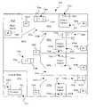
- FIG. 1is perspective view of an operating room environment showing a patient positioned atop a surgical table including an articulated frame and a mattress, a lighting system having a base unit and two light heads independently coupled to the base unit by articulated arms, an IV stand with a pair of IV bags coupled to the patient, a control station with a computer system interface to the surgical table, and a first medical device controller integrated with the operating room environment and coupled to the lighting system base unit by a telescoping and pivoting arm system and a second medical device controller shown with dashed lines integrated with the operating room environment and using a wireless communications link;
- FIG. 2is a perspective view of a controllable surgical table of the type shown in FIG. 1 , including a base having foot controls, a vertically adjustable support column coupled to the base, an articulated frame coupled to the support column, a segmented mattress system supported by the articulated frame, and a pendant remote controller for controlling surgical table functions;
- FIGS. 3–6are side elevation views of the controllable surgical table of FIG. 2 , showing the adjustable support column and articulated frame configured to support a patient in lateral, sitting, proctological, and lithotomy configurations for various medical or surgical procedures;
- FIG. 7is a block diagram showing interfaces between a medical device controller according to the present invention and a surgical table, mattress surface, heating subsystem, and lighting system;
- FIG. 8is a block diagram showing an architecture of the medical device controller of FIG. 7 , showing a processor coupled to display, user input, and device communication subsystems;
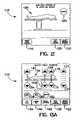
- FIG. 9is a front elevation view of a medical device controller according to the present invention showing a power button and a touch-screen display presenting an introductory menu with selection indicators for accessing controller functions to adjust a surgical table, to automatically adjust the table to predefined configurations, to adjust a mattress, or to obtain help from an on-line information guide;
- FIG. 10is a front elevation view of the medical device controller of FIG. 9 , showing a display accessed via the help selection, with selection indicators provided for obtaining introductory help information, operating instructions for controllable devices, and servicing information;
- FIG. 11is a front elevation view of the medical device controller of FIG. 9 , showing a menu display accessed via the automatically adjust selection, with selection indicators provided for selecting table configurations described by surgical procedures;
- FIG. 12is a front view of a display of a medical device controller similar to the display of FIGS. 9–11 , showing an automatic configuration screen accessed from a menu selection such as provided by FIG. 11 , the screen including an iconographic representation of a side view of a patient atop a mattress surface and articulated table frame configured consistently with the surgery description, and a selection indicator for an operator to automatically configure the table to the configuration corresponding to the iconographic representation;
- FIG. 13Ais a front view of an adjust table position screen similar to FIG. 12 , showing a table adjustment screen for adjusting a surgical table, including an iconographic representation of a patient atop a mattress surface and articulated table frame, with input indicators for adjusting articulated table frame sections and a vertically adjustable support column, input indicators for automatically leveling the table, automatically flattening the table surface, and engaging a floor brake, and selection indicators along the bottom of the display for accessing further adjustment screens;
- FIG. 13Bis a front elevation view of the medical device controller of FIG. 9 , showing an adjust table screen somewhat similar to FIG. 13A , with Trendelenburg, lateral tilt, and slide selection indicators positioned adjacent auto flat, brake, and slow adjust input indicators, and automatic table adjustment, mattress adjustment, and help information selection indicators along the bottom of the display;
- FIG. 14is a front view of a top slide screen similar to FIG. 12 , showing input indicators for sliding the table surface from end-to-end relative to the support column and for adjusting the vertical support column;
- FIG. 15is a front view of a lateral tilt screen similar to FIG. 12 , showing input indicators for tilting the table about a longitudinal axis and for adjusting the vertical support column;
- FIG. 16is a front view of a Trendelenburg adjustment screen similar to FIG. 12 , showing input indicators for tilting the table about a lateral axis and for adjusting the vertical support column;
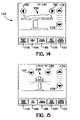
- FIG. 17is a front view of a mattress surface adjustment screen including an iconographic representation of a top view of a patient atop a mattress, with selection indicators for selecting leg, torso, and head adjustment functions, and including selection indicators along the bottom of the display to access mattress temperature adjustment and automatic mattress surface adjustment screens;
- FIG. 18is a front view of a mattress surface adjustment screen similar to FIG. 17 with a torso section of the mattress selected for adjustment, and including selection indicators for selecting regions of the torso section of the mattress for adjustment, input indicators for increasing or decreasing pressure in a selected region, and input indicators for stabilizing the mattress surface or to equalize mattress pressure;
- FIG. 19is a front view of an automatic mattress surface adjustment screen similar to FIG. 17 , including selection indicators for selecting some or all portions of the mattress for adjustment and input indicators for stabilizing, equalizing, or automatically adjusting the entire mattress by sensing pressure in each mattress region and controlling each region to conform the mattress to the patient's body;
- FIG. 20is a front view of a mattress temperature adjustment screen similar to FIG. 17 , including a temperature display and input indicators for enabling or disabling temperature control and for increasing or decreasing a designated temperature;
- FIG. 21is a front view of an alternative embodiment menu display similar to FIG. 11 with selection indicators provided for selecting predefined surgical table configurations described by doctor's names and/or surgical procedures;
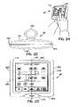
- FIG. 22is a top plan view of an embodiment of a medical device controller similar to the embodiment of FIGS. 9–11 , showing a relatively slim housing profile that is symmetric about a longitudinal axis and a generally cylindrical handle appended to a central portion of a back surface of the housing to facilitate storage and ambidextrous use of the controller;
- FIG. 23is a front elevation view of the controller of FIG. 22 showing a power button and a display;
- FIG. 24is a perspective view of the controller of FIG. 22 showing a user holding the controller with one hand and entering commands on the touch-screen with the other hand;
- FIG. 25is a top plan view of another embodiment of a medical device controller similar to the embodiment of FIGS. 9–11 , showing a housing profile with a power button and configured for holding by a left hand;
- FIG. 26is a front elevation view of the controller of FIG. 22 , showing a gripping surface and a display;
- FIG. 27is a perspective view of the controller of FIG. 22 showing a right-handed user interface
- FIG. 28is a front elevation view of another embodiment of a medical device controller, showing a tapered housing with a graphical display, semi-circular adjust and select buttons, a pair of up/down buttons, and a recessed power button, each button aligned along a central vertical axis of the housing to facilitate ambidextrous use of the controller;
- FIG. 29is a perspective view of the controller of FIG. 28 showing left-handed use of the controller
- FIGS. 30–33are front views of the display and the select and adjust buttons of the controller of FIG. 28 , showing automatic configuration selection displays similar to the configurations of FIGS. 3–6 ;
- FIG. 34is a front elevation view of another embodiment of a medical device controller similar to that of FIG. 28 , showing a tapered housing with a graphical display, three pie-shaped selection buttons, a pair of up/down buttons, and a recessed power button;
- FIG. 35is a perspective view of the controller of FIG. 24 showing left-handed use of the controller
- FIGS. 36–38are front views of the display and selection buttons of the controller of FIG. 28 , showing graphical interfaces for controlling a lighting system, a temperature control system, and a table;
- FIG. 39is a front elevation view of yet another embodiment of a medical device controller, showing a hand-held housing, a display, and several pairs of control buttons, each pair of buttons aligned along a central vertical axis of the housing to facilitate ambidextrous use of the controller;
- FIG. 40is a perspective view of the controller of FIG. 39 showing left-handed use of the controller
- FIG. 41is a block diagram showing communication between a base unit and a controller of an illustrative embodiment proximity alarm system of the present invention.
- FIG. 42is a diagrammatical representation of a portion of a healthcare facility incorporating another illustrative embodiment proximity alarm system
- FIG. 43is a diagrammatical representation of a room of a healthcare facility incorporating a further illustrative embodiment proximity alarm system
- FIG. 44is a block diagram showing communication between a monitor and an RFID tag of the proximity alarm system of FIG. 42 ;
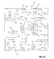
- FIG. 45is a diagrammatical representation similar to FIG. 42 illustrating another illustrative embodiment proximity alarm system
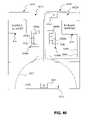
- FIG. 46is a diagrammatical representation of a portion of a healthcare facility incorporating a further illustrative embodiment proximity alarm system
- FIG. 47is a block diagram showing communication between a base unit and a controller of another illustrative embodiment proximity alarm system.
- FIG. 48is a block diagram showing communication between a base unit and a controller of a further illustrative embodiment proximity alarm system.
- a medical device controller 40is integrated into an operating room environment that includes a surgical table 42 , a surgical lighting system 44 , a control station 46 , and an IV stand 48 , as shown in FIG. 1 .
- a surgeon 50 and one or more assistants 52typically perform a procedure on a patient 54 while another care giver 56 , such as an anesthesiologist or a nurse, controls and monitors operating room equipment from control station 46 .
- Table 42 and lighting system 44provide a variety of controllable features, as discussed in more detail below.
- Controller 40provides a single, integrated, user-friendly interface for care giver 56 to control medical devices such as table 42 and lighting system 44 .
- Controller 40is a hand-held device and can be configured to control medical devices through a variety of communication interfaces.
- lighting system 44includes a base unit 64 coupled to light heads 62 via independent, articulated arms 66 .
- Controller 40can be coupled directly to based unit 64 by a telescoping arm 68 .
- Telescoping arm 68is coupled to base unit 64 by a horizontal pivot 70 and a vertical pivot 72 , and includes a distal pivot 74 , thereby providing for flexible movement of controller 40 throughout the operating room environment.
- signals between controller 40 and light heads 62can be hard-wired through arms 66 , 68 and base unit 64 .
- Controller 40is either wired directly to the controllable devices or, preferably, is configured to send signals to the controllable devices using a wireless link, such as a radio frequency (RF), infrared (IR), or ultrasound communication link.
- a wireless linksuch as a radio frequency (RF), infrared (IR), or ultrasound communication link.
- controller 40is conveniently moved around the operating room environment by care giver 56 , for example as shown by dashed lines in FIG. 1 .
- a sterile sheath(not shown), made from a suitably flexible and transparent material such as thin latex rubber, is provide to encapsulate controller 40 so that it can be safely used throughout an operating room without contaminating the sterile environment.
- the sterile sheathmay include a anti-microbial agent to further facilitate a sterile environment.
- Table 42includes articulated table frame 58 , mattress 60 , vertical support column 76 , and base 78 .
- Base 78includes a foot control panel 80 having a plurality of control buttons 82 , for adjusting vertical support column 76 , mattress 60 , and articulated table frame 58 .
- a pendant controller 81 coupled by a tether 83 to frame 58similarly includes a plurality of control buttons 85 as well as a display 87 .
- Pendant controller 81which can be coupled to table 42 at any convenient location, similarly provides for adjusting frame 58 , mattress 60 , and support column 76 .
- Articulated table frame 58includes a head section 84 , an upper back section 86 , a lower back section 88 , a seat section 90 , a pair of upper legs section 92 , and a pair lower legs section 94 .
- Sections of table frame 58are coupled to longitudinally adjacent sections via pivots so that adjacent sections can be rotated with respect to each other by motors (not shown) or other suitable actuators well-known to those skilled in the art.
- Support column 76is similarly vertically adjustable by a motor or actuator (not shown). Adjustment of articulated table frame sections 84 , 86 , 88 , 90 , 92 , 94 , and vertical support column 76 can be controlled by buttons 82 or, as discussed in more detail below, via controller 40 .
- Mattress 60illustratively includes an outer head section 96 , an inner head section 98 , a torso section 100 , and a pair of legs section 102 .
- Torso section 100 and legs section 102illustratively include a plurality of chambers 61 that are individually controllable.
- Mattress 60can be any type of controllable mattress surface, e.g., some type of fluid mattress such as an air mattress, or a vacuum bead mattress, etc.
- mattress 60illustratively is a vacuum bead air mattress system in which mattress sections 96 , 98 , 100 , and 102 can include multiple chambers and are coupled to a pressure and vacuum system to allow for selectively controlling the amount of pressure or vacuum in any chamber within any of the sections.
- Mattress 60also includes a plurality of pressure sensors (not shown) to allow for measuring pressure within any chamber of the mattress sections.
- An illustrative controllable mattressis disclosed in U.S. Pat. No. 5,966,763, entitled “Surface Pad System for a Surgical Table”, which is hereby incorporated by reference.
- Surgical table 42can be placed into configurations to support various medical or surgical procedures as shown, for example, in FIGS. 3–6 .
- controller 40provides for automatically placing table 42 in a desired, predefined configuration, such as those shown in FIGS. 3–6 , as well as for incrementally adjusting table frame 58 and mattress 60 as required to accommodate variations needed for any particular doctor 50 or patient 54 .
- controllable tablessuch as surgical table 42 are also discussed and shown in detail in U.S. Pat. Nos. 6,073,284; 6,149,674; and 6,202,230, all of which are hereby incorporated by reference.
- controller 40provides a single, mechanism for an operator, such as care giver 56 , to control features of articulated frame 58 or mattress 60 of surgical table 42 , as well as other controllable systems such as a lighting system 44 or a temperature control subsystem 104 that can be integrated with mattress 60 .
- a basic architecture for controller 40can be a processor 106 that is coupled to an I/O subsystem 108 , a memory 110 , and a communication interface 112 .
- Processor 106is illustratively a microprocessor or a microcontroller (the latter can include integral memory to alleviate the need for a separate memory 110 .) By providing a processor-based architecture with memory 110 , controller 40 can be reconfigured or reprogrammed as needed to provide for control of new or different controlled medical devices, user interface needs, or external interface requirements. It is only necessary for a controlled device to be compatible with communication interface 112 as provided with controller 40 .
- Controller 40 's I/O subsystem 108is illustratively a touch-screen display system which provides a backlit, liquid crystal display 116 .
- the touch screen input signalsare illustratively provided by a matrix of translucent, membrane-type switches (not shown) positioned above display 116 , although any touch-screen technology known to those skilled in the art can be used, such as those provided with personal digital assistant devices such as an Apple NewtonTM or PalmPilotTM devices.
- a touch-screen displayis preferred for I/O subsystem 108
- a display with buttons or switches arranged near the display screenis also contemplated.
- Communication interface 112illustratively is a pulsed infrared communication system, which technology is well known in the art.
- Table 42is coupled to an IR receiver system (not shown) that provides for receiving IR signals from controller 40 for commanding frame 58 and mattress 60 based on received IR command signals.
- IR receiver systemnot shown
- Communication interface 112can also be configured to support multiple communication protocols or interfaces, for example by including a hard-wired connection to support one controlled subsystem and an infrared connection to support other controlled subsystems.
- controller 40includes a housing 114 , a power button 115 , and a touch-screen display 116 .
- Controller 40is a hand-held unit that includes microprocessor or microcontroller 110 programmed to control a surgical table system such as that shown in FIGS. 1–6 via an IR or RF communication link 112 and to provide the user interface displays as shown in FIGS. 9–21 .
- Controller 40is powered on by depressing power button 115 , whereupon the introductory display shown in FIG. 9 is provided, which includes four touch-screen selection indicators 118 , 120 , 122 , 124 to designate to an operator access to further display interfaces for surgical table adjustment, automatic table adjustment, mattress adjustment, or accessing help information, respectively.
- Selection indicators 118 , 120 , 122 , 124are provided above touch-screen input switches included in touch-screen display 116 such as membrane switches (not shown), although, again, other touch-screen technologies can be used, or selection indicators 118 , 120 , 122 , 124 can be positioned near buttons or switches provided along edges of display 116 .
- Controller 40includes software programmed so that access of help information via selection indicator 124 from the display of FIG. 9 yields display of the help information screen of FIG. 10 .
- Help information selection indicator 124is removed, and more detailed help-related selection indicators 126 , 128 , 130 are provided for designating access to introduction, product operation, and servicing information screens. These detailed help screens provide on-line information that an operator otherwise would typically need to consult printed manuals to obtain.
- Controller 40includes software programmed so that selection via automatic table adjustment selection indicator 120 from the display of FIG. 9 yields display of an auto adjust table screen as shown in FIG. 11 .
- Automatic table adjustment selection indicator 124is removed and a descriptive menu 132 is provided for selecting various predefined configurations of surgical table 42 .
- Menu 132illustratively provides matrix of named table configurations 134 . . . 156 , in which each configuration includes text descriptive of a surgical procedure or category placed next to a button symbol.
- An operatorselects a configuration by pressing the adjacent button symbol, which is positioned on touch-screen display 116 above a touch-screen input switch.
- the descriptive textitself can be placed above one or more switches to achieve the same function by having the operator press directly above the text.
- the descriptive textcan also be alternatively displayed near a button coupled to the housing along an edge of display 116 .
- An alternative automatic table adjustment menu 232is shown in FIG. 21 , in which display 116 is partitioned into two columns each having five named table positions, with text that describes a medical or surgical configuration and in some cases an doctor's name. Although two columns of five named table positions are shown, the invention contemplates an arbitrary number of menu entries which can be presented on multiple screens or with a scrolling function.
- Alternative menu 232illustrates how controller 40 's display and processor-based architecture facilitates modifications of the user interface.
- FIG. 12a screen on display 116 based upon a selection of configuration 134 , 234 from menu 132 , 232 as shown in FIG. 11 or 21 is shown.
- Selection indicators 118 , 120 , 122 to designate access to table adjustment, automatic table adjustment, and mattress adjustment displays, respectively,are also provided.
- Iconographic representation 158provides a graphical depiction in outline form of table 42 as configured for a gall bladder procedure, including patient 54 , mattress 60 , sections 86 , 88 , 90 , 92 , 94 of articulated table frame 58 , vertical support column 76 , and base 78 . If an operator wants to adjust table 42 automatically to the gall bladder configuration as depicted in iconographic representation 158 , then the operator simply presses touch screen 116 above adjust input indicator 160 .
- Software in controller 40is configured to command table 42 to move to the predefined configuration only while a touch input is provided above adjust input indicator 160 . This “press and hold” feature provides a safety interlock in that table 42 only moves while a positive user input is provided. This also allows an operator to select an intermediate configuration by terminating the touch input above adjust input indicator 160 before table 42 reaches the predefined configuration.
- Iconographic representation 158is provided with elements of table frame 58 and mattress 60 shown in nominal positions, along with up and down adjustment input indicators 162 , 164 , 166 , 168 , 170 , 172 , 174 , 176 , auto level input indicator 178 , auto flat input indicator 180 , and brake input indicator 182 .
- Selection indicators 184 , 186 , 188are provided along the bottom of display 116 for accessing top slide, lateral tilt, and Trendelenburg adjustment display screens, as are selection indicators 120 , 122 for automatic table adjustment and mattress adjustment.
- Up and down adjustment input indicators 162 , 164 , 166 , 168 , 170 , 172 , 174 , 176provide for “press and hold” adjustment of designated sections of articulated frame 58 as indicated by the graphical display and their placement relative to iconographic display 158 .
- Up and down input indicators 162 , 164designate control of lower leg sections 94
- indicators 166 , 168designate control of lower back section 88
- indicators 170 , 172designate control of upper back section 86
- indicators 174 , 176designate control of vertical support column 76 .
- Up and down adjustment of designated sectionsprovides for fine tuning the configuration of frame 58 from any predefined configuration.
- Auto level input indicator 178provides for automatically moving all articulated sections of frame 58 to achieve a level (horizontal) configuration. Like adjust input indicator 160 discussed above, auto level input indicator 178 can be used to achieve intermediate configurations via the “press and hold” feature. Similarly, auto flat input indicator 180 provides for automatically moving all articulated sections of frame 58 to achieve a flat configuration (while maintaining any preexisting longitudinal inclination of frame 58 with respect to the ground). Brake input indicator 182 provides for locking or unlocking one or more wheels or casters (not shown) provided on base 78 of table 42 to prevent movement of table 42 along the ground.
- FIG. 13BAn alternative table adjustment display somewhat similar to FIG. 13A is shown in FIG. 13B , with input indicators performing the same functions labeled with the same reference numbers.
- the table adjustment display of FIG. 13Bdisplays only “high level” selection indicators 120 , 122 , 124 for automatic table adjustment, mattress adjustment, and help information along the bottom of display 116 .
- Selection indicators 184 , 186 , 188 for table sliding, Trendelenburg tilting, and lateral tiltingare displayed near auto flat 180 , brake 182 , and slow adjust 183 input indicators.
- FIG. 13Billustrates how controller 40 's architecture permits reprogramming to provide a user interface as desired.
- a top slide display accessible via selection indicator 184is provided for moving table frame sections 84 , 86 , 88 , 90 , 92 , 94 longitudinally relative to vertical support column 76 as shown in FIG. 14 .
- Iconographic representation 158is provided with frame 58 shown in a level configuration, although a representation showing a current configuration of articulated sections 84 , 86 , 88 , 90 , 92 , 94 can be provided.
- Head end and foot end slide input indicators 190 , 192 for sliding frame 58 longitudinally relative to vertical support column 76provide “press and hold” capability as discussed above for the up and down input indicators of FIG. 13A .
- Vertical up and down input indicators 174 , 176are also provided on display 116 , as are table adjustment, lateral tilt, Trendelenburg adjustment, automatic table adjustment, and mattress adjustment selection indicators 118 , 186 , 188 , 120 , 122 .
- a lateral tilt display accessible via selection indicator 186is provided for tilting table frame sections 84 , 86 , 88 , 90 , 92 , 94 laterally relative to vertical support column 76 as shown in FIG. 15 .
- Iconographic representation 258which shows an end view of patient 54 atop table 42 , is provided.
- Left and right tilt input indicators 190 , 192 for tilting seat frame 58 and mattress 60 laterally relative to vertical support column 76provide the “press and hold” capability as discussed above.
- Vertical up and down input indicators 174 , 176are also provided on display 116 , as are table adjustment, top slide, Trendelenburg adjustment, automatic table adjustment, and mattress adjustment selection indicators 118 , 184 , 188 , 120 , 122 .
- a Trendelenburg display accessible via selection indicator 188is provided for conjointly tilting table frame sections 84 , 86 , 88 , 90 , 92 , 94 longitudinally relative to vertical support column 76 as shown in FIG. 16 .
- Iconographic representation 158is provided with frame 58 shown in a level configuration, although, as with the display of FIG. 14 , a representation showing a current configuration of articulated sections 84 , 86 , 88 , 90 , 92 , 94 can be provided.
- Foot end down and head end down input indicators 198 , 200 for tilting frame 58 longitudinally relative to vertical support column 76provide “press and hold” capability as discussed above.
- Vertical up and down input indicators 174 , 176are also provided on display 116 , as are table adjustment, top slide, lateral tilt, automatic table adjustment, and mattress adjustment display selection indicators 118 , 186 , 188 , 120 , 122 .
- a mattress adjustment display accessible via selection indicator 122is provided for controlling features of mattress 60 as shown in FIG. 17 .
- a pictogram or iconographic representation 202depicts a plan view of patient 54 atop mattress 60 showing various chambers with leg, torso, and head mattress sections.
- Selection indicators 204 , 206 , 208are provided for selecting further screens for controlling leg 102 , torso 100 , and head 96 , 98 sections of mattress 60 .
- Automatic table adjustment, table adjustment, mattress temperature adjustment, and automatic mattress adjustment display selection indicators 118 , 120 , 210 , 212are provided near display 116 bottom.
- a torso mattress adjustment display accessible via torso selection indicator 204is provided for controlling torso section 100 of mattress 60 as shown in FIG. 18 .
- Iconographic representation 202 and leg and head mattress section selection indicators 204 , 208are provided as shown in FIG. 17 .
- Torso mattress section chamber selection indicators 214 , 216 , 218 , 220 , 222 , 224 , 226are provided near their corresponding locations on iconographic representation 202 , along with lines indicating the correspondence.
- One or more mattress section chamberscan be selected by depressing its indicator, which results in a reverse video display of that indicator to indicate its selection.
- Inflation increase and decrease input indicators 228 , 230are provided for increasing or decreasing pressure in one or more selected mattress sections, using a “press and hold” paradigm as discussed above.
- Stabilize input indicator 231 and equalize input indicator 233are provided near increase and decrease input indicators 228 , 230 .
- the stabilize featurestiffens one or more selected sections of vacuum bead mattress 60 by creating a vacuum in the corresponding chamber(s) to withdraw fluid from selected section(s).
- the equalize featureadjusts selected mattress sections to a baseline level by setting pressure in corresponding chambers to a baseline level to prepare for a new patient or procedure.
- the torso mattress adjustment displayalso includes automatic table adjustment, table adjustment, mattress temperature adjustment, and automatic mattress adjustment selection indicators 120 , 118 , 210 , 212 displayed along the bottom of display 116 . Similar display screens (not shown) are provided for controlling leg and head sections 102 , 96 , 98 of mattress 60 .
- An automatic mattress adjustment display accessible via automatic mattress adjustment selection indicator 212includes iconographic representation 202 , leg, torso, and head mattress section selection indicators 204 , 206 , 208 , an all mattress section selection indicator 235 , and stabilize, equalize, and automatically adjust input indicators 231 , 233 , 237 as shown in FIG. 19 .
- the all mattress selection indicator 235provides a shorthand mechanism for selecting all sections. The stabilize and equalize functions work as discussed above for FIG. 18 , except that all chambers within a selected mattress section are automatically designated for a selected mattress section.
- Selection of automatically adjust input indicator 237uses pressure sensors within each chamber or cell (not shown) coupled to mattress 60 to conform mattress 60 automatically to a patient's body by varying pressures to each chamber based on sensed pressure.
- automatic table adjustment, table adjustment, mattress temperature adjustment, and automatic mattress adjustment selection indicators 120 , 118 , 210 , 212displayed along the bottom of display 116 .
- a mattress temperature adjustment display accessible via mattress temperature adjustment selection indicator 210includes iconographic representation 202 , temperature subsystem on and off buttons 239 , 241 for enabling or disabling the temperature control subsystem, target temperature increase and decrease input indicators 243 , 245 , and a target temperature display value 247 .
- This displayillustrates control of an optional temperature control subsystem (not shown) that controls the entire mattress temperature to a particular target value, such as by using a temperature controlled fluid supply to the mattress, a thermal-resistive covering of the mattress, etc.
- further temperature control featurescan be provided, such as separate temperature control for different mattresses regions or sections, display of actual temperature(s) of the mattress surface, facilities for cycling temperature over various periods and ranges, etc. This highlights a basic advantage of controller 40 's architecture, which facilitates integration of additional features or controlled subsystems into a single interface.
- Controller 40further provides for programming and storing desired configurations of table frame 58 and mattress 60 for subsequent recall from auto adjust menu 132 .
- a “save config” input indicator(not shown) provided from appropriate display screens such as the adjust table screens of FIGS. 13A and 13B provides access to a “save named configuration” screen (not shown) that prompts the user for entry of a configuration name through use of an alphabetic keypad provided on display 116 .
- Management functions for manipulating saved configurationsfurther provide for deleting, renaming, reordering, etc. of stored configurations.
- controller 40is designed to support its use by either a left-handed or right-handed operator.
- An essentially “ambidextrous” deviceis provided by housing 114 and display 116 that are substantially symmetric about a longitudinal axis 261 of controller 40 .
- Housing 114has relatively flat front and back surfaces 249 , 251 coupled by rounded side edges 253 , bottom edge 263 , and top edge 265 .
- Display 116 and power button 115are coupled to front surface 249 .
- display 116covers most of front surface 249 of housing 114 so that a relatively large display with large, easy-to-see touch-screen buttons are provided in a portable, hand-held unit.
- Housing 114includes a handle 255 appended to back surface 251 .
- Handle 255is configured with a cylindrical shape having a somewhat elliptical cross-section to facilitate ease of grasping and holding.
- Handle 255is configured to retain rechargeable batteries (not shown) that provide power for controller 40 .
- the cylindrical shape of handle 255further facilitates coupling controller 40 to a retaining socket (not shown) for temporary or permanent storage.
- the retaining socketcan be provided on an IV pole, equipment bracket, or wall, or anywhere in an operating room environment, and is configured to provide for battery recharging either with a direct voltage coupling or through an indirect magnetic field charging system.
- Handle 255further provides a support to allow for sitting controller 40 upright by placing controller bottom surface 263 on a table or other surface.
- a generally cylindrical handle 255is shown, those skilled in the art will see the abundance of variations possible for configuring alternative handles to facilitate holding controller 40 and coupling it to items found throughout the operational environment, such as an operating room, to facilitate temporary or
- controller 340includes the same display 116 as controller 40 , mounted in an asymmetric housing 314 and having a side-mounted power button 315 .
- Controller 340includes a left-handed gripping surface 317 so that operation of touch-screen buttons is made by a care giver's right hand.
- Controller 340can, however, be programmed so that all screens are displayed “upside down”, thus converting controller 340 from a right-handed configuration to a left-handed configuration. This shows the utility of the programmable architecture of the present invention.
- Controller 440includes a tapered housing 414 coupled to recessed power button 415 , up and down buttons 402 , 404 , semi-circular adjust and select buttons 406 , 408 , a display 416 , and a control cable 419 .
- housing 414 and display 416are substantially symmetric about a longitudinal axis to permit equally simple use by left-handed or right-handed operators.
- controller 440uses only the four input buttons 402 , 404 , 406 , 408 , and varies the functions performed by these buttons based on the information presented and selected on display 416 .
- Controller 440indicates a single selection of an item on display 416 , such as a single controllable feature, a predefined overall configuration of a controlled system, or another controller option. Controller 440 provides for slewing designation of the selected item to other selectable items based on user input to select button 408 . Pressing adjust button 406 when a predefined overall configuration is designated, such as one of the table configurations illustrated in FIGS. 30–33 , results in controller 440 commanding the controlled system to assume the predefined configuration. As with controller 40 , adjust button 406 can provide a “press and hold” capability.
- Pressing adjust button 406 when a controllable feature is designatedallows for use of up and down buttons 402 , 404 to control the designated feature, such as moving a particular section of an articulated surface, or controlling pressure of a portion of a controllable mattress, etc. Pressing adjust button 406 when another controller option is designated will result in controller 440 's displaying of another display screen with selectable items.
- Controller 540includes a tapered housing 514 coupled to recessed power button 415 , up and down buttons 402 , 404 , pie-shaped adjust, select, and equipment buttons 506 , 508 , 510 , a display 516 , and a control cable 519 .
- housing 514 and display 516are substantially symmetric about a longitudinal axis to permit equally simple use by left-handed or right-handed operators.
- Controller 540 's display 516is the same as display 416 , with controller 540 similarly programmed to provide information on display 516 , such as an iconographic representation 558 , along with other indicia indicating controllable features and other selectable controller menu options.
- Iconographic representation 558varies to represent the controlled system by displaying a stylized lighthead as shown in FIG. 36 , temperature display as shown in FIG. 37 , and surgical table as shown in FIG. 37 .
- a light intensity indicator bar 560is provided as shown in FIG. 36 , which varies an amount displayed in reverse video to represent the percentage light intensity currently being output by the lighthead.
- the temperature display of FIG. 37is updated to indicate an actual controlled temperature value
- the iconographic table representation of FIG. 38is presented in correspondence with the current surgical table configuration.
- controller 540Operation of controller 540 is the same as for controller 440 except that controller 540 includes equipment button 510 , which is used to switch between different controlled systems. Thus, rather than selecting a displayed item to switch between controlled systems, controller 540 automatically toggles between controlled systems when an operator presses equipment button 510 . This provides a convenient mechanism for quickly switching via single press of a button to a desired system, such as the lighting system of FIG. 36 , the temperature control system of FIG. 37 , and the table system of FIG. 38 .
- controller 640includes a handheld housing 614 , a display 616 , eight pairs of buttons 650 . . . 680 , and a power button 682 as shown in FIGS. 39–40 .
- Controller 640including its buttons 650 . . . 682 , is symmetric about a longitudinal axis 661 to facilitate ambidextrous use.
- Buttons 650 . . . 680include indicia that represent their respective table control functions and provide “press and hold” control as discussed above.
- Buttons 650 , 652provide a table high/low functions
- buttons 654 , 656provide Reverse/Reverse Trendelenburg functions
- buttons 658 , 660provide lateral tilt left/right functions
- buttons 662 , 664provide back up/down functions
- buttons 666 , 668provide upper back up/down functions
- buttons 670 , 672provide leg up/down functions
- buttons 674 , 676provide slide lower/upper functions
- button 678provides an auto flat function
- button 680provides a high speed button to increase table speed when depressed simultaneously with another of buttons 650 . . . 678 .
- Controller 640provides a sealed housing that is durable, easy to clean, and suitable for use in sterile environments. Buttons 650 . . .
- Controller 640can be a pendant controller tethered to table 42 similar to controller 81 of FIG. 2 or can be configured as a wireless controller.
- the controllers 40 , 340 , 440 , 540 , and 640each may be wired directly to controllable devices, or may be configured to send signals to the controllable devices using a wireless link, such as a radio frequency (RF), infrared (IR), or ultrasound communication link.
- a wireless linksuch as a radio frequency (RF), infrared (IR), or ultrasound communication link.
- each controller 40 , 340 , 440 , 540 , and 640is mobile to increase room efficiency
- the mobility of the controller 40 , 340 , 440 , 540 , and 640also allows the controller 40 , 340 , 440 , 540 , and 640 to be removed from the operating room. Removal of the controller 40 , 340 , 440 , 540 , and 640 is usually not desirable in that the gained efficiency is lost when the controller 40 , 340 , 440 , 540 , and 640 can not be located by the caregiver 56 .
- a proximity alarm system 710 including a locating or proximity sensing deviceis associated with the controller 740 .
- the controller 740illustratively includes an alarm 754 that alerts a user or caregiver 56 attempting to transport the controller 740 away from a predetermined location or item, such as the controllable medical device, or the room within which the controllable medical device is located.
- the alarm 754may comprise an audible alarm, such as a horn or buzzer.
- the alarmmay comprise a visual alarm, such as a light, or a vibratory alarm for providing a tactile sensation to a person in proximity to the alarm.
- the alarm 754may be in the form of an electronic transmission to a personal computer, portable data assistant, cellular phone, pager, or other similar portable device.
- controllable medical devicewill be described as a patient support, such as surgical table 42 .
- controller 740may be coupled to other controllable medical devices, such as surgical lighting system 44 , as detailed above.
- Other aspects of the controller 740may be substantially the same as those detailed above with respect to controller 40 .
- proximity alarm system 710includes transmitters 744 , 746 and receivers 748 , 750 of signals carried by a wireless energy source, such as radio frequency (RF), infrared (IR), or ultrasound.
- a wireless energy sourcesuch as radio frequency (RF), infrared (IR), or ultrasound.
- a first transmitter 744 and a first receiver 748are associated with the controllable medical device, and are illustratively located in a base unit 752 coupled to the patient support 42 .
- a second transmitter 746 and a second receiver 750are coupled to the housing 114 of the controller 740 .
- the first transmitter 744 of the base unit 752illustratively emits a radio frequency (RF) signal 753 that is received by the second receiver 750 of the controller 740 .
- the second transmitter 746 of the controller 740sends out a RF signal 755 that is received by the first receiver 748 .
- the distance between the controller 740 and the base unit 752can be determined. If the distance is larger than a predetermined maximum, the alarm 754 is activated.
- the alarm 754is preferably located at the controller 740 , but may be at the base unit 752 or elsewhere. The predetermined maximum distance may be customized as desired.
- the second receiver 750 of controller 740is initially in a receive-only mode waiting for the RF signal 753 from first transmitter 744 of the base unit 752 which has been suitably coded by a modulation coder, illustratively incorporated within a first processor 756 .
- a modulation coderillustratively incorporated within a first processor 756 .
- a second processor 758demodulates the signal 753 , and logically checks the frequency and/or code.
- the second processor 758illustratively includes a phase-locked loop oscillator (not shown) which is locked in a frequency and phase relationship with a control oscillator (not shown) of the first processor 756 of the base unit 752 .
- the second processor 758then switches off the second receiver 750 and causes the second transmitter 746 to transmit RF signal 755 back to the base unit 752 , suitably coded, and on a different frequency after amplifying the signal 755 through an amplifier (not shown).
- the first processor 756 of the base unit 752has turned off the first transmitter 744 and has caused the first receiver 748 to enter a receive mode.
- the processor 756demodulates the signal 755 , checks the code, and applies the modulating component to a phase detector of the first processor 756 to compare the phase of the returning signal 755 against its reference oscillator.
- the phase-shift of the demodulated signal 755corresponds to the round-trip time-delay between the base unit 752 and the controller 748 and can be used to operate a suitably calibrated meter to indicate the distance or range between the base unit 752 and the controller 740 . Additional details of the alarm system 710 may be of the type disclosed in U.S. Pat. No. 4,908,627, the disclosure of which is expressly incorporated herein by reference.
- a proximity alarm system 810operates by being integrated with a tracking system 812 .
- the tracking system 812separately tracks two items, such as the controller 740 and the base unit 752 . More particularly, the controller 740 and the base unit 752 have identification (ID) tags 814 and 816 , respectively, coupled to them and which are identifiable and trackable by the tracking system 812 .
- the tracking system 812is configured to link ID tags 814 and 816 in a central tracking computer or processor 818 . ID tags 814 and 816 that are linked are known by the processor 818 to be associated and required to remain within a predetermined proximity to each other.
- the alarm system 810communicates with the tracking system 812 , which tracks both linked items 740 and 752 , and either determines the distance between them or determines if they are located in the same room 822 . A determination that the distance between the linked items 740 and 752 exceeds a predetermined value, or that the linked items 740 and 752 are in different rooms 822 , causes the processor 818 to activate the alarm 754 .
- the tracking system 812includes a plurality of monitors or detectors 820 positioned in different locations within a care facility, a hospital, or other area being monitored.
- the monitors 820may comprise conventional receivers or transceivers, and each room 822 of the hospital typically includes at least one monitor 820 .
- the monitors 820each include a sensor to detect identification (ID) signals being generated by the tags 814 and 816 and/or to excite the tags 814 and 816 to generate the ID signals. If monitors 820 in different rooms 822 each sense one of linked tags 814 and 816 , then the processor 818 knows that linked items 740 and 752 have been separated and the alarm 754 is activated.
- IDidentification
- each component associated with a particular room 822is identified by its reference number followed by a letter corresponding to a particular room 822 a, 822 b, 822 c, 822 d, and 822 e, respectively.
- the monitor 820 c associated with room 822 cdetects tag 816 c coupled to base unit 752 c.
- the monitor 820 e ′ associated with hallway 822 edetects tag 814 c coupled to controller 740 c.
- Signals sent from the monitors 820 c and 820 e ′are received by the processor 818 which determines that the controller 740 c is located in hallway 822 e while the base unit 752 c is located in room 822 c.
- the processor 818activates the alarm 754 c located within the controller 740 c to provide an alert to the caregiver 56 that the controller 740 c has been separated from the patient support 42 c by an unacceptable distance.
- the processor 818knows the position of each monitor 820 and the distances between the monitors 820 .
- the monitors 820locate the linked ID tags 814 and 816 by triangulation or other conventional method, and compare the locations of linked tags 814 and 816 .
- the alarm 754is activated.
- room 822 aincludes first and second monitors 820 a and 820 g which together provide information regarding locations of the tags 814 a and 816 a to the processor 818 . If the processor 818 determines that the linked items 740 a and 752 a have become separated by an amount exceeding a predetermined value, then the processor 818 activates the alarm 754 a located within the controller 740 a.
- the locations of the controller 740 and the base unit 752are each determined by identifying which monitor 820 receives an ID signal from respective tags 814 and 816 associated therewith.
- An infrared (IR) line-of-sight tracking systemis one type of such locating and tracking system.
- Another illustrative typeis passive RF transmitters and absolute reference position (ARP) sensors. The system knows that the controller 740 and the base unit 752 are generally in the area of the monitor(s) 820 receiving the signals from the tags 814 and 816 .
- signal strength of the ID signals received from the tags 814 and 816are used to better approximate the location of the corresponding controller 740 and base unit 752 relative to the monitor(s) 820 .
- the tags 814 and 816are interrogated or caused to send the respective ID signals and the respective times it takes for the signals to reach the monitor(s) 820 are used to better approximate the location of the corresponding controller 740 and base unit 752 relative to the monitor(s) 820 .
- the locations of the controller 740 and the base unit 752are each determined by two or more fixed-location monitors 820 that each receive an ID signal from the respective tag 814 and 816 associated therewith.
- Such systemsdetermine the location of the controller 740 and the base unit 752 by determining a distance measurement for each monitor 820 that is indicative of the distance from the respective monitor 820 to the respective tag 814 , 816 .
- the distance measurements for the monitors 820are then used to determine the location of the controller 740 and the base unit 752 in either two dimensions or three dimensions. In one variation, the distance measurements are based on the time it takes for the ID signal from the tag 814 , 816 to reach each monitor 820 .
- the distance measurementsare based on the signal strength of the ID signal received at each monitor 820 . In yet another variation, the distance measurements are based on a combination of both time and signal strength.
- the location of the controller 740 and the base unit 752may be classified as being within a given region or zone of an area of interest or as being within a sphere of space having a center that corresponds to the best approximation of the location of the respective controller 740 and base unit 752 and a periphery corresponding to the resolution of the system.
- the monitors 820are configured to monitor the entrances/exits, illustratively the doorways 823 of rooms 822 as shown in FIG. 43 .
- the processor 818is configured to activate the alarm 754 when one of the ID tags 814 ′ and 816 ′ passes through, or within proximity of, the doorway 823 .
- items 740 and 752 that belong in a certain area or room 822can be retained in that room 822 .
- the processor 818 in such an embodimentmay be instructed to allow passage of first and second ID tags 814 ′ and 816 ′ into and out of the room 822 when the linked first ID tag 814 ′ enters or leaves the room 822 with the second linked ID tag 816 ′. Furthermore, in cases where an item needs to be serviced, the processor 818 may be instructed to allow passage of the item 740 , 752 and the associated ID tag 814 ′, 816 ′ through the monitored doorway 823 .
- each ID tag 814 ′ and 816 ′comprises a transponder tag which is physically connected to the controller 740 and the base unit 752 , respectively.
- the monitor 820 ′illustratively comprises an exciter/reader located at a respective doorway 823 such that the tagged items 740 and 752 must pass by the monitor 820 ′ before exiting the room 822 .
- the monitor 820 ′generates and transmits a surveillance excitation signal 825 , which is illustratively an RF signal, but may comprise any wireless signal including IR or ultrasound.
- the tags 814 ′, 816 ′When within a receiving range of the monitor 820 ′, the tags 814 ′, 816 ′ receive the RF surveillance excitation signal 825 and, in the absence of a deactivation instruction, respond thereto by generating and transmitting a surveillance response signal 827 , which again is illustratively an RF signal but may comprise any wireless signal.
- the monitor 820 ′receives the RF surveillance response signal 827 which is then transmitted to the processor 818 which, in turn, activates the respective alarm 754 through an alarm signal 829 . Additional details of the alarm system 810 ′ may be similar to those detailed in U.S. Pat. No. 5,874,896, the disclosure of which is expressly incorporated herein by reference.
- a plurality of monitors 820 ′may act as exciters/readers and generate excitation signals 825 which are received by tags 814 ′ and 816 ′. Both tags 814 ′ and 816 ′ receive the generated excitation signals from the monitors 820 ′ and generate ID signals, or surveillance response signals 827 , corresponding to the respective tag 814 ′ and 816 ′.
- the excitation signals 825include a monitor ID
- the surveillance response signals 827include a tag ID and the received monitor ID.
- a distance measurement between tags 814 ′ and 816 ′may be determined by monitors 820 ′ by comparing the round trip time (from generation of the excitation signal 825 to reception of the respective surveillance response signal 827 ) to receive surveillance response signals 827 by each of the monitors 820 ′.
- a single monitor 820 ′may be provided in an area or room 822 along with multiple fixed exciters (not shown). Each exciter is configured to generate an excitation signal 825 , which is received by monitor 820 ′ and by tags 814 ′ and 816 ′. Each excitation signal 825 includes a unique ID to identify the respective exciter. Tags 814 ′ and 816 ′, in response to receiving an excitation signal 825 , generates an ID signal, or surveillance response signal 827 , which includes a unique ID associated with respective tags 814 ′ and 816 ′ and the unique ID of the exciter(s), which generated the received excitation signal.
- tags 814 and 816 of FIG. 42may each include data about the base unit 752 of the patient support 42 and the controller 740 , such as a unique item identifier.
- Tags 814 and 816 and the associated data gathering system described belowmay employ a variety of different technologies and incorporate the locating and tracking system 812 .
- tags 814 and 816may include a transmitter similar to that detailed above in base unit 752 and controller 740 of proximity alarm system 810 , and a memory, or use bar-code technology to store and convey the data.
- tags 814 and 816may operate utilizing any conventional wireless technology, including RF, IR, and ultrasound.
- tags 814 and 816may include a radio frequency identification (RFID) device (either active or passive) for providing the data to a receiver as described below.
- RFIDradio frequency identification
- RFID tags 814 and 816may be configured for read-only operation, volatile read/write operation, or write once/read many (WORM) operation.
- WORMwrite once/read many
- active RFID tags 814 and 816are substantially identical and may each include a transmitter, and a receiver (or a transceiver 824 ), an antenna 826 , and a battery 828 to provide power to transceiver 824 .
- Tag 814 , 816may further include a memory 830 to store data relating to its respective item 752 and 740 , and modulation circuitry 832 to provide a tag signal 834 conveying such information as further described below.
- active RFID tags 814 , 816may further include a conventional power savings circuit 836 that interrupts or reduces the supply of power to the tag components when tag 814 , 816 remains inactive (does not transmit or receive information) for a predetermined period of time.
- Tag 814 , 816remains in this power savings mode until it next receives a signal from a monitor or detector 820 as further described below.
- Passive RFID tags 814 , 816may include similar components. Typically, passive RFID tags 814 , 816 reflect RF signals received from detectors 820 , and add information relating to item 740 , 752 . More specifically, when tag 814 , 816 comes with range of a detector 820 , the tag's antenna 826 receives an RF detector signal 836 transmitted by detector 820 . Signal 836 may also be used to provide power to tag 814 , 816 as is well-known in the art. Thus, passive RFID tags 814 , 816 may not include a battery 828 . Battery 828 may, however, be included in passive RFID tags 814 , 816 to provide power to tag memory 830 (if any), or modulation circuitry 832 .
- tag modulation circuitry 832encodes a tag signal 834 with the desired information (such as the unique item identifier).
- Tag signal 834is then transmitted back to detector 820 either via the same antenna 826 that received detector signal 836 , or another transmission antenna included on tag 814 , 816 .
- Tags 814 , 816may be packaged in a variety of ways.
- tags 814 , 816(including the transceiver, antenna, and any other components) may be enclosed within a container, case, or package adapted for attachment to item 740 , 752 using adhesive, clips, or any other suitable attachment method.
- tags 814 , 816may be incorporated into a label for application (via adhesive or some other suitable attachment method) to item 740 , 752 .
- Such labelsmay be printed using special printers, such as those produced by Zebra Technologies of Vernon Hills, Ill., that employ printing technology similar to that employed by conventional bar-code printers.
- Detector 820 for use with RFID tags 814 , 816generally includes an antenna 838 , a transceiver 840 , a reader 842 , and communication electronics 844 including antenna 846 for wirelessly communicating with a central processing system, such as master processor or station 818 .
- communication electronics 844could alternatively be hardwired to master processor 818 .
- Transceivers 840transmit the RF energy of detector signal 836 to activate passive tags 814 , 816 (or active tags 814 , 816 in power savings mode) and power the response transmission (tag signal 834 ) from passive tags 814 , 816 .
- transceiver 840is coupled to antenna 838 and reader 842 .
- Antenna 838generates an electrical field defining the range of detector 820 .
- the antenna 838may be incorporated into a doorway of patient rooms 822 , a pass-through wall of a facility, a waste receptacle, a cabinet, or a variety of other structural elements or pieces of equipment.
- Detector reader 842controls the transmission of detector signals 836 by transceiver 840 and antenna 838 , and receives and processes tag signals 834 from tags 814 , 816 as received by antenna 838 and transceiver 840 .
- Reader 842includes communication electronics 844 , decoding electronics 850 for decoding the information included in tag signals 834 , and software 852 .
- the decoded informationis provided to communication electronics 844 for transmission to, for example, master processor 818 .
- Software 852may implement anti-collision algorithms as are commonly known in the art to permit substantially simultaneous reception of multiple tag signals 834 .
- monitors 820By incorporating monitors 820 at various locations throughout the healthcare facility (e.g., doorways to patient rooms 822 , operating rooms, recovery rooms, entryways to particular areas of the facility, etc.), the location of items 740 , 752 equipped with tags 814 , 816 may be automatically tracked using locating and tracking system 812 .
- FIG. 45Another illustrative tracking system 912 for use with the proximity alarm system 910 of the present invention is shown in FIG. 45 .
- Those items in FIG. 45 with the same reference numbers as items in FIG. 42identify like components.
- the tracking system 912includes a plurality of transmitters 920 , at least one tag 814 associated with each controller 740 , a receiver 924 , and a central processor 818 .
- Transmitters 920are configured to generate an ID signal (not shown) containing a unique ID associated with the respective transmitter 920 .
- the transmitter IDmay be set by the setting of a conventional dip switch associated with each of transmitters 920 .
- transmitters 920include one of an IR transmitter, an ultrasound transmitter, or other line-of-sight transmitter.
- transmitters 920include a low-frequency RF transmitter.
- Transmitters 920in one example, include a battery (not shown) to provide power to generate the respective ID signal.
- transmitters 920are coupled to a power supply (not shown) such as a facility electrical system.
- Each tag 814is configured to receive the ID signal generated by transmitters 920 when tag 814 is proximate to one of transmitters 920 .
- tag 814 breceives the ID signal generated by transmitter 920 b because tag 814 b is located in patient room 822 b.
- Each tag 814is configured to generate an ID signal associated with the respective tag 814 .
- the tag ID signalincludes an ID unique to the respective tag 814 (controller 740 ) and at least the last received transmitter ID from one of transmitters 920 .
- tag 814generates an ID signal every time tag 814 receives a new transmitter ID, such as when tag 814 leaves the room 822 associated with the patient support 42 and enters hallway 822 e proximate to transmitter 920 e, 920 e ′.
- tag 814generates a tag ID signal at a predetermined interval and includes all transmitter IDs received since the previously transmitted tag ID signal.
- tag 814transmits the tag ID signal at two or more predetermined time intervals based on a characteristic of a displacement sensor (not shown) associated with tag 814 .
- tag 814is configured to store one or more transmitter IDs for later transmission in a tag ID signal.
- Tag 814includes an RF transmitter or other transmitter that is capable of sending the tag ID signal to receiver 924 which may be centrally located in facility. As such, the transmitters 920 associated with tags 814 must be capable of penetrating facility walls and other obstructions.
- Receiver 924is connected to central computing device 818 through either a wired or wireless connection.
- the location of transmitters 920are stored in or otherwise made available to central computing device 818 .
- the location of tags 814are determined by correlating the transmitter ID(s) transmitted with the tag ID signal with the known locations of transmitters 920 .
- Central computing device 818stores the location information related to each tag 814 for later processing or retrieval.
- the proximity alarm system 1010includes an alarm 754 a coupled to a controller 1040 a , the alarm 754 a configured to be activated when the controller 1040 a is positioned within an undesirable or forbidden area 1012 .
- a transmitter 1044is positioned in the forbidden area 1012 , which is illustrated as a portion of a hallway 1016 outside of the room 1022 a where the controller 1040 a is to be kept.
- the controller 1040 aincludes a receiver 1048 a coupled to a processor 1058 a which is coupled to the alarm 754 a.
- the receiver 1048 ais configured to receive a signal transmitted from the transmitter 1044 .
- the signal transmitted from the transmitter 1044may comprise a radio frequency (RF), infrared (IR), ultrasound or other wireless signal which defines a border or perimeter 1013 of the forbidden area 1012 .
- RFradio frequency
- IRinfrared
- ultrasoundor other wireless signal which defines a border or perimeter 1013 of the forbidden area 1012 .
- the receiver 1048 aUpon entering the forbidden area 1012 , the receiver 1048 a receives the signal from the transmitter 1044 and the alarm 754 a is activated.
- the transmitter 1044 ′may be coupled to an antenna 1046 which emits a signal to establish a border or perimeter 1050 enclosing a room 1022 b where the controller 1040 b is to be kept. As the controller 1040 b approaches the perimeter 1050 , signals from the antenna 1046 are received by the receiver 1048 b , which then causes the controller 1040 b to activate the alarm 754 b. Additional details of an illustrative proximity alarm 1010 ′ may be found in U.S. Pat. No. 6,111,508, the disclosure of which is expressly incorporated herein by reference.
- the proximity alarm system 1110includes a base unit 1152 having a transmitter 1144 , and a controller 1140 having a receiver 1048 configured to receive signals 1145 transmitted by the transmitter 1144 .
- the signals 1145 sent from the transmitter 1144illustratively comprise low power radio frequency (RF) signals in order to comply with the Federal Communications Commission (FCC) regulations.
- a processor 1058is in communication with the receiver 1048 and is configured to activate an alarm 754 when the receiver 1048 receives a signal 1145 from the transmitter 1144 that is below a predetermined threshold strength. It is well-known that the greater the distance between the transmitter 1144 and the receiver 1048 , the weaker the signal 1145 will be when received by the receiver 1048 .
- the distance between the base unit 1152 and the controller 1140may be determined by detecting the signal strength received by the receiver 1048 . When the signal strength is below a predetermined value, then the processor 1058 activates the alarm 754 . Additional details of an illustrative proximity alarm system 1110 may be found in the U.S. Pat. Nos. 5,614,886, 5,289,163, and 4,871,997, the disclosures of which are expressly incorporated herein by reference.
- the proximity alarm system 1210is configured to activate an alarm 754 when a predetermined time interval expires since communication between a base unit 1152 and a controller 1240 .
- the base unit 1152includes a transmitter 1144 which sends a short radio frequency (RF) pulse signal 1245 for receipt by a receiver 1048 of the controller 1240 .
- a processor 1058is in communication with the receiver 1048 and with a counter or clock 1242 .
- the processor 1058Each time the RF pulse signal 1245 is received by the receiver 1048 , the processor 1058 resets the counter 1242 .
- the counter 1242may be of conventional design and counts or accumulates successive time intervals. If the number of successive time intervals accumulated by the counter 1242 reaches a predetermined value, the processor 1058 activates the alarm 754 to inform a user that the controller 1240 is out of a desired range or is malfunctioning indicating that communication with the base unit 1152 is not possible.
- the predetermined value for activating the alarm 754is based upon a desired range of travel of the controller 1240 . Upon bringing the controller 1240 back into the desired range, RF pulse signals 1245 from the transmitter 1144 may again be received by the receiver 1048 .
- the processor 1058resets the counter 1242 , typically to a value of zero. Additional details of the proximity alarm system 1210 may be found in U.S. Pat. Nos. 4,908,627 and 5,722,059, the disclosures of which are expressly incorporated herein by reference.
- the proximity alarms 754may be located within the controller 740 , 1040 , 1140 , 1240 within the base unit 752 , 1152 coupled to the patient support 42 , or in another location remote both from the controller and the base unit.
- the alarm 754 positioned remote from the controller 740 , 1040 , 1140 , 1240may be desirable in a multi-patient support environment where it could be difficult to associate a controller with a particular device/patient support 42 .
- the alarm 754 within the base unit 752 , 1152 attached to the device/patient support 42will thereby communicate to the user which device/patient support 42 is associated with the displaced controller 740 , 1040 , 1140 , 1240 .
- controller 740 , 1040 , 1140 , 1240can be switched to a tracking mode where the controller tracks the base unit 752 , 1152 to tell the user where the base unit is located.
- a controller 740 , 1040 , 1140 , 1240 with a tracking modeis described in U.S. Pat. No. 5,650,769, the disclosure of which is expressly incorporated herein by reference.
- Additional featuresmay be common to all embodiments of the proximity alarm system.
- One such featureis a controller call button illustratively coupled to the device/patient support 42 . Pressing the button activates a signal device, illustratively the alarm 754 , within the controller 740 , 1040 , 1140 , 1240 thereby assisting the user in locating the controller.
- Another common featuremay be a controller release button. The controller release button disables the proximity alarm system 710 thereby allowing the controller 740 , 1040 , 1140 , 1240 to extend beyond the normal boundaries without the alarm 754 sounding. Such a feature is desirable when the controller 740 , 1040 , 1140 , 1240 must be removed from the room in instances such as repair or software/hardware updating.
- a controllerthus provides a single, hand-held control unit that can operate multiple medical devices, such as both a surgical table and a mattress system.
- the controllerpermits both wireless operation or a conventional cable system.
- a displayis provided, such as a relatively large, backlit display, that is easy to see and understand, and provides a friendly user-interface without using small buttons.
- Touch-screen display 116preferably is flat, easy to clean, and durable.
- the controllerprovides a menu driven system that effectively displays to a user the information necessary for any given adjustment of a controlled system, thus optimizing the ease and effectiveness of its use.
Landscapes
- Health & Medical Sciences (AREA)
- Life Sciences & Earth Sciences (AREA)
- Animal Behavior & Ethology (AREA)
- General Health & Medical Sciences (AREA)
- Public Health (AREA)
- Veterinary Medicine (AREA)
- Engineering & Computer Science (AREA)
- Biomedical Technology (AREA)
- Nursing (AREA)
- Accommodation For Nursing Or Treatment Tables (AREA)
Abstract
Description
Claims (30)
Priority Applications (1)
| Application Number | Priority Date | Filing Date | Title |
|---|---|---|---|
| US10/430,643US7010369B2 (en) | 1997-11-07 | 2003-05-06 | Medical equipment controller |
Applications Claiming Priority (4)
| Application Number | Priority Date | Filing Date | Title |
|---|---|---|---|
| US6470997P | 1997-11-07 | 1997-11-07 | |
| US09/187,825US6351678B1 (en) | 1997-11-07 | 1998-11-06 | Medical equipment controller |
| US10/083,197US6560492B2 (en) | 1997-11-07 | 2002-02-26 | Medical equipment controller |
| US10/430,643US7010369B2 (en) | 1997-11-07 | 2003-05-06 | Medical equipment controller |
Related Parent Applications (1)
| Application Number | Title | Priority Date | Filing Date |
|---|---|---|---|
| US10/083,197Continuation-In-PartUS6560492B2 (en) | 1997-11-07 | 2002-02-26 | Medical equipment controller |
Publications (2)
| Publication Number | Publication Date |
|---|---|
| US20030195644A1 US20030195644A1 (en) | 2003-10-16 |
| US7010369B2true US7010369B2 (en) | 2006-03-07 |
Family
ID=28794856
Family Applications (1)
| Application Number | Title | Priority Date | Filing Date |
|---|---|---|---|
| US10/430,643Expired - Fee RelatedUS7010369B2 (en) | 1997-11-07 | 2003-05-06 | Medical equipment controller |
Country Status (1)
| Country | Link |
|---|---|
| US (1) | US7010369B2 (en) |
Cited By (69)
| Publication number | Priority date | Publication date | Assignee | Title |
|---|---|---|---|---|
| US20040261178A1 (en)* | 2003-06-04 | 2004-12-30 | Hartmut Gnoyke | Patient examination support system |
| US20050245821A1 (en)* | 2004-03-05 | 2005-11-03 | Assaf Govari | Position sensing system for orthopedic applications |
| US20060020353A1 (en)* | 1999-12-30 | 2006-01-26 | Microsoft Corporation | Providing distributed scene programming of a home automation and control system |
| US20060117482A1 (en)* | 2004-12-07 | 2006-06-08 | Branson Gregory W | Touch screen control for lateral rotation of a hospital bed mattress |
| US20060162083A1 (en)* | 2005-01-27 | 2006-07-27 | Hill-Rom Services, Inc. | Bed trapeze lift with bed controls, lights and patient transferability |
| US20060255904A1 (en)* | 2005-05-10 | 2006-11-16 | Uwe Danzer | Medical examination or treatment device, in particular x-ray or CT device |
| US20060271207A1 (en)* | 2004-11-05 | 2006-11-30 | Mark Shaw | Mattress monitoring system |
| USD533516S1 (en)* | 2005-07-25 | 2006-12-12 | Family Co., Ltd. | Remote controller for massaging apparatus |
| US20070016443A1 (en)* | 2005-07-13 | 2007-01-18 | Vitality, Inc. | Medication compliance systems, methods and devices with configurable and adaptable escalation engine |
| US20070101497A1 (en)* | 2005-11-10 | 2007-05-10 | Maquet Gmbh & Co. Kg | Hydraulic column clamping |
| US20070101500A1 (en)* | 2005-11-10 | 2007-05-10 | Maquet Gmbh & Co. Kg | Apparatus for adjusting the bed of an operating table |
| US20070110448A1 (en)* | 2005-11-14 | 2007-05-17 | Jurgen Ruch | Method and device for bidirectional IR data transfer between a medical treatment table and an operator control device |
| US20070107129A1 (en)* | 2005-11-14 | 2007-05-17 | Maquet Gmbh & Co. Kg | Patient bed for an operating table |
| US20070107124A1 (en)* | 2005-11-14 | 2007-05-17 | Maquet Gmbh & Co. Kg | Patient bed system |
| US20070107126A1 (en)* | 2005-11-14 | 2007-05-17 | Maquet Gmbh & Co. Kg | Device for adjusting an operating table |
| US20070107125A1 (en)* | 2005-11-14 | 2007-05-17 | Maquet Gmbh & Co. Kg | Operating table |
| US20070116512A1 (en)* | 2005-11-14 | 2007-05-24 | Maquet Gmbh & Co. Kg | Joint arrangement for the connection of two segments of a patient bed |
| US20070118989A1 (en)* | 2005-11-14 | 2007-05-31 | Maquet Gmbh & Co. Kg | Patient bed system |
| US20070169268A1 (en)* | 2005-12-19 | 2007-07-26 | Stryker Corporation | Hospital bed |
| US20080058967A1 (en)* | 2006-08-31 | 2008-03-06 | Siemens Aktiengesellschaft | Medical apparatus and method |
| US20080099043A1 (en)* | 2006-10-31 | 2008-05-01 | Icon Systems, Llc | Automated appendage cleaning apparatus with brush |
| US20080100441A1 (en)* | 2006-10-31 | 2008-05-01 | Timothy Prodanovich | Sanitizer dispensers with compliance verification |
| US20080099049A1 (en)* | 2006-10-31 | 2008-05-01 | Icon Systems, Llc | Wash chamber for automated appendage-washing apparatus |
| US20080103636A1 (en)* | 2006-10-31 | 2008-05-01 | James Glenn | Automated Washing System With Compliance Verification And Automated Compliance Monitoring Reporting |
| US20080159482A1 (en)* | 2006-09-14 | 2008-07-03 | Philipp Quaet-Faslem | Medical system with user interface embodied to allow switchover |
| US20080174425A1 (en)* | 2007-01-22 | 2008-07-24 | Microsoft Corporation | Object detection framework for set of related objects |
| US20090043253A1 (en)* | 2005-10-11 | 2009-02-12 | Blake Podaima | Smart medical compliance method and system |
| US20090099862A1 (en)* | 2007-10-16 | 2009-04-16 | Heuristic Analytics, Llc. | System, method and computer program product for providing health care services performance analytics |
| US20090121865A1 (en)* | 2007-11-14 | 2009-05-14 | Hamel Andrew J | System and method for automatically powering on and synchronizing a wireless remote console to a central control unit so as to allow remote control of a medical device |
| US20090134181A1 (en)* | 2005-07-13 | 2009-05-28 | Vitality, Inc. | Medication dispenser with automatic refill |
| US20090267776A1 (en)* | 2008-04-29 | 2009-10-29 | Meritech, Inc. | Hygiene compliance |
| US20100073168A1 (en)* | 2008-09-19 | 2010-03-25 | Tallent Dan R | System and Method for Reporting Status of a Bed |
| US20100270257A1 (en)* | 2005-07-13 | 2010-10-28 | Vitality, Inc. | Medicine Bottle Cap With Electronic Embedded Curved Display |
| US20100328099A1 (en)* | 2005-07-13 | 2010-12-30 | Vitality, Inc. | Night Light With Embedded Cellular Modem |
| US20110018687A1 (en)* | 2007-11-13 | 2011-01-27 | Universitetet I Oslo | Ultrasound zone location system with high capacity |
| US8006332B2 (en) | 2005-12-19 | 2011-08-30 | Stryker Corporation | Hospital bed |
| US8344860B2 (en) | 2004-08-02 | 2013-01-01 | Hill-Rom Services, Inc. | Patient support apparatus alert system |
| US8400311B2 (en) | 1999-03-05 | 2013-03-19 | Hill-Rom Services, Inc. | Hospital bed having alert light |
| US8464380B2 (en) | 2005-07-08 | 2013-06-18 | Hill-Rom Services, Inc. | Patient support apparatus having alert light |
| US20130255699A1 (en)* | 2012-04-02 | 2013-10-03 | TurnCare, Inc. | Patient-orienting alternating pressure decubitus prevention support apparatus |
| CN103999136A (en)* | 2011-10-18 | 2014-08-20 | 德沃特奥金有限公司 | Electromotive furniture drive and method for controlling an electromotive furniture drive |
| US20140250597A1 (en)* | 2013-03-11 | 2014-09-11 | Select Comfort Corporation | Adjustable bed foundation system with built-in self-test |
| US9539155B2 (en) | 2012-10-26 | 2017-01-10 | Hill-Rom Services, Inc. | Control system for patient support apparatus |
| US20170017758A1 (en)* | 2015-04-15 | 2017-01-19 | Infusystem Holdings, Inc. | Integrated system for obtaining information from electronic medical records and method of use |
| US9655798B2 (en) | 2013-03-14 | 2017-05-23 | Hill-Rom Services, Inc. | Multi-alert lights for hospital bed |
| US9833907B1 (en) | 2015-06-22 | 2017-12-05 | X Development Llc | Proximity-based binding |
| US9862099B1 (en) | 2015-06-22 | 2018-01-09 | X Development Llc | Haptic controller with touch-sensitive control knob |
| US10052249B2 (en) | 2004-10-29 | 2018-08-21 | Stryker Corporation | Patient support with improved control |
| US10206836B2 (en) | 2011-11-11 | 2019-02-19 | Hill-Rom Services, Inc. | Bed exit alerts for person support apparatus |
| WO2019123464A1 (en)* | 2017-12-21 | 2019-06-27 | P-Cure, Ltd. | Patient positioning apparatus and method |
| US10347255B1 (en) | 2018-03-08 | 2019-07-09 | Ces Advancements, Llc | Healthcare systems and methods using voice inputs |
| CN110251343A (en)* | 2019-04-25 | 2019-09-20 | 天津冬儒工艺品有限公司 | A crystal therapy bed |
| US20190350780A1 (en)* | 2018-05-21 | 2019-11-21 | Hill-Rom Services, Inc. | Patient support apparatus adaptable to multiple modes of transport |
| US10629052B2 (en) | 2015-10-28 | 2020-04-21 | Hill-Rom Services, Inc. | Bed alert condition configuration using a remote computer device |
| USD893547S1 (en) | 2018-08-28 | 2020-08-18 | DePuy Synthes Products, Inc. | Surgical pump display screen or portion thereof with graphical user interface |
| US10797524B2 (en) | 2017-10-24 | 2020-10-06 | Stryker Corporation | Techniques for power transfer through wheels of a patient support apparatus |
| US10835431B2 (en)* | 2013-06-06 | 2020-11-17 | MAQUET GmbH | Apparatus and method for controlling an operating table |
| US10874776B2 (en) | 2017-09-01 | 2020-12-29 | Medos International Sarl | Methods, systems, and devices for joint to pump elevation level user interfaces, autocalibration for joint elevation, and joint pressure estimation |
| US10910888B2 (en) | 2017-10-24 | 2021-02-02 | Stryker Corporation | Power transfer system with patient transport apparatus and power transfer device to transfer power to the patient transport apparatus |
| US10945902B2 (en) | 2017-11-13 | 2021-03-16 | Stryker Corporation | Techniques for controlling actuators of a patient support apparatus |
| US11039962B2 (en) | 2012-04-02 | 2021-06-22 | TurnCare, Inc. | Non-invasive pressure-mitigation apparatuses for improving blood flow and associated systems and methods |
| US11103398B2 (en) | 2017-05-17 | 2021-08-31 | Hill-Rom Services, Inc. | Flexible overhead arm |
| US11139666B2 (en) | 2017-10-24 | 2021-10-05 | Stryker Corporation | Energy harvesting and propulsion assistance techniques for a patient support apparatus |
| US11246776B2 (en) | 2005-12-19 | 2022-02-15 | Stryker Corporation | Patient support with improved control |
| US11394252B2 (en) | 2017-10-24 | 2022-07-19 | Stryker Corporation | Power transfer system with patient support apparatus and power transfer device to transfer power to the patient support apparatus |
| US11389357B2 (en) | 2017-10-24 | 2022-07-19 | Stryker Corporation | Energy storage device management for a patient support apparatus |
| US12178949B2 (en) | 2020-10-09 | 2024-12-31 | TurnCare, Inc. | Pressure-mitigation apparatuses for improved treatment of immobilized patients and associated systems and methods |
| USD1055957S1 (en)* | 2019-05-08 | 2024-12-31 | Sleep Number Corporation | Display screen or portion thereof with graphical user interface |
| US12370108B2 (en) | 2020-10-09 | 2025-07-29 | TurnCare, Inc. | Pressure-mitigation apparatuses for improved treatment of respiratory illnesses and associated systems and methods |
Families Citing this family (63)
| Publication number | Priority date | Publication date | Assignee | Title |
|---|---|---|---|---|
| US8235919B2 (en) | 2001-01-12 | 2012-08-07 | Celleration, Inc. | Ultrasonic method and device for wound treatment |
| US7914470B2 (en) | 2001-01-12 | 2011-03-29 | Celleration, Inc. | Ultrasonic method and device for wound treatment |
| US20030080191A1 (en) | 2001-10-26 | 2003-05-01 | Allen Lubow | Method and apparatus for applying bar code information to products during production |
| EP1466297A4 (en) | 2001-12-17 | 2005-10-19 | Int Barcode Corp | Double-sided bar code doubling as a single bar code |
| US7183913B2 (en)* | 2003-05-30 | 2007-02-27 | Vane Line Bunkering, Inc. | Life raft container security system and method |
| FR2868291B1 (en)* | 2004-03-30 | 2008-01-18 | Hill Rom Sas Soc Par Actions S | REST APPARATUS FOR A PATIENT |
| US9463287B1 (en)* | 2004-09-20 | 2016-10-11 | Bing Innovations, Llc | Controlling usage of replaceable tool ends |
| US9168340B2 (en) | 2009-03-27 | 2015-10-27 | Bing Innovations, Llc | System and method for pain reduction during skin puncture and breakable tip therefor |
| WO2010110823A1 (en) | 2009-03-27 | 2010-09-30 | Bing Innovations, Llc | Apparatus and method for reducing pain during skin puncturing procedures |
| US7443303B2 (en) | 2005-01-10 | 2008-10-28 | Hill-Rom Services, Inc. | System and method for managing workflow |
| DE102005003784A1 (en)* | 2005-01-18 | 2006-07-27 | Aesculap Ag & Co. Kg | Surgical system and control unit for a surgical system |
| DE102005022347B4 (en)* | 2005-05-13 | 2010-08-12 | Siemens Ag | Medical basic system and medical technology system |
| US7785277B2 (en)* | 2005-06-23 | 2010-08-31 | Celleration, Inc. | Removable applicator nozzle for ultrasound wound therapy device |
| US7713218B2 (en)* | 2005-06-23 | 2010-05-11 | Celleration, Inc. | Removable applicator nozzle for ultrasound wound therapy device |
| CN101258357B (en)* | 2005-07-20 | 2010-04-21 | 奥普蒂姆斯服务有限公司 | Focused positioning of surgical lighting in the ceiling |
| FI118674B (en) | 2005-11-22 | 2008-02-15 | Planmeca Oy | Hardware in a dental environment and a method for controlling a hardware device |
| US20070199154A1 (en)* | 2006-02-24 | 2007-08-30 | Escaross Essam B | System and method for adjusting pressure in pockets or zones |
| DE102006008598A1 (en)* | 2006-02-24 | 2007-08-30 | Arno Friedrichs | Reclining device has mattress, and data interface is present over which valve controllable data are displayed and received wirelessly |
| ITTV20060040A1 (en)* | 2006-03-16 | 2007-09-17 | Univ Degli Studi Udine | SYSTEMS AND METHODS FOR THE LOCALIZATION OF OBJECTS. |
| US7703020B2 (en)* | 2006-03-31 | 2010-04-20 | General Electric Company | Medical diagnostic system interface |
| US8491521B2 (en) | 2007-01-04 | 2013-07-23 | Celleration, Inc. | Removable multi-channel applicator nozzle |
| US20080172454A1 (en)* | 2007-01-12 | 2008-07-17 | Pixads, Llc | System for Providing Multimedia Content to Customers and Method Thereof |
| US9642759B2 (en)* | 2007-04-13 | 2017-05-09 | Stryker Corporation | Patient support with universal energy supply system |
| US9414804B2 (en)* | 2007-08-24 | 2016-08-16 | General Electric Company | Diagnostic imaging device having protective facade and method of cleaning and disinfecting same |
| EP2793154B1 (en) | 2008-05-27 | 2021-03-31 | Stryker Corporation | Wireless medical room control arrangement for control of a plurality of medical devices |
| DE102008051133A1 (en)* | 2008-10-10 | 2010-04-22 | Logicdata Electronic & Software Entwicklungs Gmbh | Arrangement with an electronically adjustable piece of furniture and method for wireless operation thereof |
| FR2938427B1 (en)* | 2008-11-19 | 2010-12-10 | Steris Surgical Technologies | DEVICE FOR CONTROLLING AN OPERATING TABLE |
| FR2951628B1 (en)* | 2009-10-22 | 2012-07-13 | Genourob | IMPROVEMENTS IN THE DEVICE FOR DETECTING AND FOLLOWING A TOTAL OR PARTIAL LESION OF CROSS LIGAMENT BEFORE THE KNEE, BY COMPARISON BETWEEN THE TWO MEMBERS |
| FI125658B (en)* | 2011-10-12 | 2015-12-31 | Merivaara Oy | Method for controlling an operating table using a portable device |
| US9569591B2 (en)* | 2012-05-31 | 2017-02-14 | Hill-Rom Services, Inc. | Configurable user interface systems for hospital bed |
| DE102012220672A1 (en)* | 2012-11-13 | 2014-05-15 | Trumpf Medizin Systeme Gmbh + Co. Kg | Medical control system |
| DE102013103757B4 (en) | 2013-04-15 | 2017-06-29 | MAQUET GmbH | Method and device for operating a mobile operating table |
| DE102013104538B4 (en)* | 2013-05-03 | 2015-05-21 | MAQUET GmbH | Operating table and method for controlling an operating table |
| CN105208897B (en)* | 2013-05-10 | 2018-06-01 | 德沃特奥金有限公司 | Handheld controller for a motorized furniture driver, method for detecting actuation of the handheld controller, and motorized furniture driver |
| US20160136026A1 (en)* | 2013-06-14 | 2016-05-19 | Segars California Partners, Lp | Infant Warming Device with Remote Display and Control |
| WO2015080901A1 (en) | 2013-11-26 | 2015-06-04 | Celleration Inc. | Systems and methods for producing and delivering ultrasonic therapies for wound treatment and healing |
| US10750875B2 (en)* | 2014-01-02 | 2020-08-25 | Sleep Number Corporation | Adjustable bed system having split-head and joined foot configuration |
| US10285508B2 (en) | 2014-01-02 | 2019-05-14 | Sleep Number Corporation | Adjustable bed system with split head and split foot configuration |
| US9582851B2 (en)* | 2014-02-21 | 2017-02-28 | Microsoft Technology Licensing, Llc | Using proximity sensing to adjust information provided on a mobile device |
| EP3782577A1 (en)* | 2014-03-21 | 2021-02-24 | Biolase, Inc. | Dental laser interface system and method |
| US9999468B2 (en) | 2014-05-29 | 2018-06-19 | The Spectranetics Corporation | Remote control switch for a laser system |
| US9940810B2 (en)* | 2014-11-19 | 2018-04-10 | Stryker Corporation | Person support apparatuses with patient mobility monitoring |
| US10695508B2 (en) | 2015-05-01 | 2020-06-30 | Bing Innovations, Llc | Reducing pain of skin piercing using vibration |
| DE102015113074B4 (en)* | 2015-08-07 | 2017-06-29 | MAQUET GmbH | Power management and deep discharge protection |
| DE102015215820A1 (en)* | 2015-08-19 | 2017-02-23 | Siemens Healthcare Gmbh | Controlling a medical device |
| GB2550211A (en)* | 2016-05-13 | 2017-11-15 | Linde Ag | A gas cylinder monitoring system |
| CN106691381A (en)* | 2016-12-23 | 2017-05-24 | 华中科技大学同济医学院附属协和医院 | Medical intelligent bracelet and medical smart monitoring system and method |
| JP6568884B2 (en)* | 2017-02-28 | 2019-08-28 | 株式会社メディカロイド | Robot operating table and operation device for robot operating table |
| JP6599913B2 (en)* | 2017-02-28 | 2019-10-30 | 株式会社メディカロイド | Robot operating table operating device |
| JP6821520B2 (en)* | 2017-06-23 | 2021-01-27 | 日本光電工業株式会社 | Sensors and biometric information processing systems |
| CN108109684A (en)* | 2017-11-07 | 2018-06-01 | 苏州麦迪斯顿医疗科技股份有限公司 | A kind of procedure bulletin method and system, storage medium, electronic equipment |
| US10382094B2 (en) | 2017-11-28 | 2019-08-13 | International Business Machines Corporation | Cable tracking by electromagnetic emission |
| CA3089618A1 (en) | 2018-01-26 | 2019-08-01 | Bing Innovations, L.L.C. | Reducing pain at a medical treatment site |
| GB2572615B (en)* | 2018-04-05 | 2021-10-13 | Steris Solutions Ltd | Handset for controlling a surgical operating table |
| US20200000442A1 (en)* | 2018-06-28 | 2020-01-02 | General Electric Company | System and method for selecting a patient position and an equipment configuration for a medical procedure |
| US12403054B2 (en)* | 2019-06-07 | 2025-09-02 | James P Janniello | Methods, systems, and apparatus for an adjustable bed frame based on biometric information |
| US11175809B2 (en) | 2019-08-19 | 2021-11-16 | Capital One Services, Llc | Detecting accessibility patterns to modify the user interface of an application |
| US11030506B2 (en)* | 2019-09-19 | 2021-06-08 | International Business Machines Corporation | Multi-tag encoding for reducing tag tampering in instant checkout |
| ES3008025T3 (en) | 2019-12-20 | 2025-03-21 | Dewertokin Tech Group Co Ltd | Electric motor-powered furniture drive |
| EP3915508B1 (en)* | 2020-05-29 | 2025-09-10 | Baxter Medical Systems GmbH + Co. KG | System comprising surgical table and surgical light |
| CN112245209A (en)* | 2020-11-06 | 2021-01-22 | 中国人民解放军陆军特色医学中心 | Head fixing device in thyroid surgery |
| EP4000575A1 (en)* | 2020-11-19 | 2022-05-25 | TRUMPF Medizin Systeme GmbH + Co. KG | Surgical table and method for controlling a surgical table |
| US20220384011A1 (en)* | 2021-05-28 | 2022-12-01 | Cilag GmbH Internation | Efficiency of motion monitoring and analysis for a surgical procedure |
Citations (158)
| Publication number | Priority date | Publication date | Assignee | Title |
|---|---|---|---|---|
| US3439320A (en) | 1967-09-21 | 1969-04-15 | Relton Corp | Personnel location system |
| US3739329A (en) | 1971-05-24 | 1973-06-12 | Recognition Devices | Electronic system for locating |
| US4151407A (en) | 1977-04-28 | 1979-04-24 | Texas Instruments Incorporated | Low-power, infrared information transmission system |
| US4211998A (en) | 1977-08-25 | 1980-07-08 | Stierlen-Maquet Aktiengesellschaft | Method of and remote control apparatus for remotely controlling a medical appliance |
| US4216462A (en) | 1978-03-06 | 1980-08-05 | General Electric Company | Patient monitoring and data processing system |
| US4225953A (en) | 1978-09-29 | 1980-09-30 | Simon William F | Personnel locator |
| US4231019A (en) | 1977-08-24 | 1980-10-28 | Stierlen-Maquet Aktiengesellschaft | Remote control arrangement for a medical appliance |
| US4244596A (en) | 1979-01-29 | 1981-01-13 | Chung Tae D | Steering controlling apparatus for trailers |
| US4275385A (en) | 1979-08-13 | 1981-06-23 | Bell Telephone Laboratories, Incorporated | Infrared personnel locator system |
| US4435862A (en) | 1981-10-19 | 1984-03-13 | Simmons Universal Corporation | Control arrangement and method for an adjustable bed |
| US4601064A (en) | 1983-01-13 | 1986-07-15 | Fisher Berkeley Corporation | Communication system |
| US4649385A (en) | 1982-08-13 | 1987-03-10 | Teloc R & D Ltd. | Electronic locating system for persons receiving telephone calls |
| US4680790A (en) | 1985-08-22 | 1987-07-14 | Joerns Healthcare, Inc. | Bedside control module for healthcare stations and the like |
| US4712105A (en) | 1985-03-12 | 1987-12-08 | U.S. Philips Corporation | Remote control hand apparatus for operating different modules |
| US4745647A (en) | 1985-12-30 | 1988-05-24 | Ssi Medical Services, Inc. | Patient support structure |
| US4769584A (en) | 1985-06-18 | 1988-09-06 | Thomas J. Ring | Electronic controller for therapeutic table |
| US4825200A (en) | 1987-06-25 | 1989-04-25 | Tandy Corporation | Reconfigurable remote control transmitter |
| US4837568A (en) | 1987-07-08 | 1989-06-06 | Snaper Alvin A | Remote access personnel identification and tracking system |
| US4850040A (en) | 1987-07-01 | 1989-07-18 | Inncom International, Inc. | Infrared remote control system for activating and deactivating one or more devices in a single enclosed space |
| US4871997A (en) | 1987-06-30 | 1989-10-03 | Tech-Age International Corporation | Proximity sensor apparatus |
| EP0348726A2 (en) | 1988-06-25 | 1990-01-03 | Nokia (Deutschland) GmbH | Remote control arrangement |
| US4908627A (en) | 1985-06-14 | 1990-03-13 | Santos James P | Monitoring, ranging and locating devices |
| GB2193359B (en) | 1986-07-31 | 1990-07-11 | Multitone Electronics Plc | Area communications systems |
| EP0373912A3 (en) | 1988-12-16 | 1990-09-12 | Contour Beds Limited | Relaxation and massage apparatus |
| US4967195A (en) | 1986-05-08 | 1990-10-30 | Shipley Robert T | Hospital signaling and communications system |
| CH675936A5 (en) | 1988-04-26 | 1990-11-15 | Magnetic Elektromotoren Ag | Linear drive control e.g. for adjustable bed - uses remote control signals with automatic disconnection of control unit upon disconnection of drive |
| US4990892A (en) | 1989-08-07 | 1991-02-05 | Westcom, A Division Of Westside Communications Of Jacksonville, Inc. | Personnel locator system |
| US4999622A (en) | 1988-06-28 | 1991-03-12 | Sony Corporation | Remote commander having a ROM read-out pre-programmed codes therefrom |
| US5016172A (en) | 1989-06-14 | 1991-05-14 | Ramp Comsystems, Inc. | Patient compliance and status monitoring system |
| US5027314A (en) | 1988-03-17 | 1991-06-25 | United Manufacturing Co., Inc. | Apparatus and method for position reporting |
| US5051741A (en) | 1990-03-28 | 1991-09-24 | Wesby Philip B | Locating system |
| US5062151A (en) | 1983-01-13 | 1991-10-29 | Fisher Berkeley Corporation | Communication system |
| US5072463A (en) | 1991-04-11 | 1991-12-17 | Willis William J | EZ access bed |
| US5073999A (en) | 1989-05-22 | 1991-12-24 | Ssi Medical Services, Inc. | Method for turning a patient with a low air loss patient support |
| US5119104A (en) | 1990-05-04 | 1992-06-02 | Heller Alan C | Location system adapted for use in multipath environments |
| US5153584A (en) | 1989-03-17 | 1992-10-06 | Cardiac Evaluation Center, Inc. | Miniature multilead biotelemetry and patient location system |
| EP0316643B1 (en) | 1987-11-13 | 1993-02-03 | Preh-Werke GmbH & Co. KG | Remote control device |
| US5199118A (en) | 1991-02-11 | 1993-04-06 | World Dryer, Division Of Specialty Equipment Companies, Inc. | Hand wash station |
| US5202666A (en) | 1991-01-18 | 1993-04-13 | Net/Tech International Inc. | Method and apparatus for enhancing hygiene |
| JPH0595978A (en) | 1991-10-07 | 1993-04-20 | Paramount Bed Co Ltd | Control system for motor-driven bed |
| EP0543763A1 (en) | 1991-11-21 | 1993-05-26 | Nicoletti Agregats S.A. | Container with personalized access, for collecting objects of specific origin |
| GB2230365B (en) | 1989-02-18 | 1993-05-26 | Olivetti Research Ltd | Mobile carrier tracking system |
| US5218344A (en) | 1991-07-31 | 1993-06-08 | Ricketts James G | Method and system for monitoring personnel |
| US5235713A (en) | 1990-11-06 | 1993-08-17 | Bio Clinic Corporation | Fluid filled flotation mattress |
| US5239300A (en) | 1988-12-16 | 1993-08-24 | Telehotel-Tv-Systeme Gmbh | Operating unit for manual control of a plurality of functions in different apparatuses |
| US5251349A (en) | 1989-03-09 | 1993-10-12 | Ssi Medical Services, Inc. | Multi-modal patient support system |
| US5289163A (en) | 1992-09-16 | 1994-02-22 | Perez Carla D | Child position monitoring and locating device |
| US5309144A (en) | 1990-04-19 | 1994-05-03 | Lacombe David K | Proximity sensing security system |
| US5317303A (en) | 1992-09-11 | 1994-05-31 | Anro Engineering, Inc. | Batteryless sensor used in security applications |
| US5317309A (en) | 1990-11-06 | 1994-05-31 | Westinghouse Electric Corp. | Dual mode electronic identification system |
| US5319363A (en) | 1990-08-31 | 1994-06-07 | The General Hospital Corporation | Network for portable patient monitoring devices |
| EP0488552B1 (en) | 1990-11-28 | 1994-08-10 | Huntleigh Technology Plc | Beds |
| EP0455852B1 (en) | 1990-05-09 | 1994-08-10 | Siemens Aktiengesellschaft | Medical and, in particular, dental device |
| US5363425A (en) | 1992-06-29 | 1994-11-08 | Northern Telecom Limited | Method and apparatus for providing a personal locator, access control and asset tracking service using an in-building telephone network |
| FR2705952A1 (en) | 1993-06-04 | 1994-12-09 | Atik Sarl | Installation for collection and temporary storing of refuse |
| US5387993A (en) | 1993-06-25 | 1995-02-07 | Precision Tracking Fm, Inc. | Method for receiving and transmitting optical data and control information to and from remotely located receivers and transmitters in an optical locator system |
| US5390238A (en) | 1992-06-15 | 1995-02-14 | Motorola, Inc. | Health support system |
| US5396224A (en) | 1991-11-22 | 1995-03-07 | Hewlett-Packard Company | Telemetered patient location system and method |
| US5410326A (en) | 1992-12-04 | 1995-04-25 | Goldstein; Steven W. | Programmable remote control device for interacting with a plurality of remotely controlled devices |
| GB2265038B (en) | 1992-03-11 | 1995-05-03 | Olivetti Res Ltd | Tracking and identification system |
| US5417222A (en) | 1994-01-21 | 1995-05-23 | Hewlett-Packard Company | Patient monitoring system |
| US5426425A (en) | 1992-10-07 | 1995-06-20 | Wescom, Inc. | Intelligent locator system with multiple bits represented in each pulse |
| USRE35035E (en) | 1980-10-06 | 1995-09-12 | Fisher Berkeley Corporation | Locating system and method |
| USD362660S (en) | 1994-06-17 | 1995-09-26 | Maxwell Products, Inc. | Remote control for a bed |
| US5455851A (en) | 1993-07-02 | 1995-10-03 | Executone Information Systems, Inc. | System for identifying object locations |
| US5458123A (en) | 1992-12-16 | 1995-10-17 | Siemens Medical Systems, Inc. | System for monitoring patient location and data |
| USD363552S (en) | 1993-12-10 | 1995-10-24 | Jb Research, Inc. | Wand for a massage system |
| US5465082A (en) | 1990-07-27 | 1995-11-07 | Executone Information Systems, Inc. | Apparatus for automating routine communication in a facility |
| US5471404A (en) | 1993-12-23 | 1995-11-28 | Mazer; Murray S. | Occlusion detection system for locator devices |
| US5493283A (en) | 1990-09-28 | 1996-02-20 | Olivetti Research Limited | Locating and authentication system |
| US5509154A (en) | 1994-11-01 | 1996-04-23 | Select Comfort Corporation | Air control system for an air bed |
| US5515426A (en) | 1994-02-28 | 1996-05-07 | Executone Information Systems, Inc. | Telephone communication system having a locator |
| US5534876A (en) | 1994-03-10 | 1996-07-09 | Motorola, Inc. | Multipath tolerant location system and method therefor |
| US5541585A (en) | 1994-10-11 | 1996-07-30 | Stanley Home Automation | Security system for controlling building access |
| US5542136A (en) | 1994-08-05 | 1996-08-06 | Stryker Corporation | Portable mattress for treating decubitus ulcers |
| US5542138A (en)* | 1995-02-06 | 1996-08-06 | Williams; Terry N. | Bedside control unit for a hospital bed |
| US5544376A (en) | 1994-01-31 | 1996-08-13 | Maxwell Products, Inc. | Articulated bed with customizable remote control |
| US5548637A (en) | 1993-09-09 | 1996-08-20 | Precision Tracking Fm, Inc. | Method and apparatus for locating personnel and objects in response to telephone inquiries |
| US5561412A (en) | 1993-07-12 | 1996-10-01 | Hill-Rom, Inc. | Patient/nurse call system |
| US5572195A (en) | 1994-08-01 | 1996-11-05 | Precision Tracking Fm, Inc. | Sensory and control system for local area networks |
| US5576952A (en) | 1993-03-09 | 1996-11-19 | Metriplex, Inc. | Medical alert distribution system with selective filtering of medical information |
| US5588009A (en) | 1994-02-03 | 1996-12-24 | Will; Craig A. | Personal paging, communications, and locating system |
| US5589821A (en)* | 1994-12-13 | 1996-12-31 | Secure Technologies, Inc. | Distance determination and alarm system |
| US5594786A (en) | 1990-07-27 | 1997-01-14 | Executone Information Systems, Inc. | Patient care and communication system |
| US5610589A (en) | 1995-02-09 | 1997-03-11 | Bennie R. Evans | Method and apparatus for enforcing hygiene |
| US5611096A (en) | 1994-05-09 | 1997-03-18 | Kinetic Concepts, Inc. | Positional feedback system for medical mattress systems |
| US5614886A (en) | 1995-10-13 | 1997-03-25 | Snell; Peter | Article removal alarm system for use with portable electronic device |
| US5627584A (en)* | 1991-01-17 | 1997-05-06 | Olympus Optical Co., Ltd. | Endoscope system with centralized control of associated peripheral equipment |
| US5627524A (en) | 1993-06-07 | 1997-05-06 | Lifecom, Llc | Infrared locator system |
| US5633742A (en) | 1994-09-21 | 1997-05-27 | Fisher Berkeley Corporation | Optical data communication and location apparatus, system and method and transmitters and receivers for use therewith |
| US5650770A (en)* | 1994-10-27 | 1997-07-22 | Schlager; Dan | Self-locating remote monitoring systems |
| US5650769A (en) | 1995-02-24 | 1997-07-22 | Ntp, Incorporated | Radio receiver for use in a radio tracking system and a method of operation thereof |
| EP0788984A1 (en) | 1996-02-09 | 1997-08-13 | Alois Pöttinger Maschinenfabrik GmbH | Method and device to check the quantity of refuse delivered to a refuse collecting installation |
| USD382645S (en) | 1996-04-21 | 1997-08-19 | Jb Research, Inc. | Hand wand for massaging apparatus |
| USD382543S (en) | 1995-08-11 | 1997-08-19 | Hsieh Shun Tsung | Multiple-function controller for electric massage sofa |
| US5664270A (en) | 1994-07-19 | 1997-09-09 | Kinetic Concepts, Inc. | Patient interface system |
| US5670945A (en) | 1995-07-06 | 1997-09-23 | Applonie; Alan R. | Self-monitoring hand-sanitizing station |
| US5678568A (en) | 1993-07-27 | 1997-10-21 | Olympus Optical Co., Ltd. | System control apparatus, medical system control apparatus and image-plane display method of medical system control apparatus |
| US5699038A (en) | 1993-07-12 | 1997-12-16 | Hill-Rom, Inc. | Bed status information system for hospital beds |
| US5719555A (en)* | 1993-06-24 | 1998-02-17 | Cart Watch, Inc. | Golf cart control and monitoring apparatus and system using digital signal modulation techniques |
| US5722059A (en) | 1995-02-24 | 1998-02-24 | Ntp Incorporated | Radio receiver for use in a radio tracking system and a method of operation thereof |
| US5742233A (en) | 1997-01-21 | 1998-04-21 | Hoffman Resources, Llc | Personal security and tracking system |
| US5754997A (en) | 1994-08-15 | 1998-05-26 | Midmark Corporation | Support cushion for surgery table |
| US5759149A (en) | 1993-12-17 | 1998-06-02 | Hill-Rom, Inc. | Patient thermal support device |
| US5771511A (en) | 1995-08-04 | 1998-06-30 | Hill-Rom, Inc. | Communication network for a hospital bed |
| US5774865A (en) | 1996-04-19 | 1998-06-30 | Ideal Ideas, Inc. | Patient compliance and monitoring system for multiple regimens using a movable bar code reader |
| US5781942A (en) | 1989-07-12 | 1998-07-21 | Sloan Valve Company | Wash stations and method of operation |
| US5787528A (en) | 1995-10-04 | 1998-08-04 | Antinori; Santino | Method and apparatus for providing bed recall functions |
| US5796338A (en)* | 1997-02-03 | 1998-08-18 | Aris Mardirossian, Inc. | System for preventing loss of cellular phone or the like |
| US5812059A (en) | 1996-02-23 | 1998-09-22 | Sloan Valve Company | Method and system for improving hand cleanliness |
| US5815865A (en)* | 1995-11-30 | 1998-10-06 | Sleep Options, Inc. | Mattress structure |
| US5815864A (en) | 1996-04-02 | 1998-10-06 | Sytron Corporation | Microprocessor controller and method of initializing and controlling low air loss floatation mattress |
| US5822544A (en) | 1990-07-27 | 1998-10-13 | Executone Information Systems, Inc. | Patient care and communication system |
| FR2753183B1 (en) | 1996-09-12 | 1998-10-30 | D Entreprises Automobiles Comp | WASTE COLLECTION TROLLEY, ASSEMBLY COMPRISING SUCH A TROLLEY AND USE OF SUCH AN ASSEMBLY |
| US5835013A (en) | 1997-10-30 | 1998-11-10 | Duterte; Fred V. | Wireless purse-snatcher/luggage alarm |
| US5838223A (en) | 1993-07-12 | 1998-11-17 | Hill-Rom, Inc. | Patient/nurse call system |
| US5874896A (en) | 1996-08-26 | 1999-02-23 | Palomar Technologies Corporation | Electronic anti-shoplifting system employing an RFID tag |
| EP0899215A1 (en) | 1997-08-26 | 1999-03-03 | MIPI Constructions B.V. | Container for automated differentiated waste collection |
| US5900801A (en) | 1998-02-27 | 1999-05-04 | Food Safety Solutions Corp. | Integral master system for monitoring food service requirements for compliance at a plurality of food service establishments |
| US5901172A (en) | 1997-06-11 | 1999-05-04 | Multispectral Solutions, Inc. | Ultra wideband receiver with high speed noise and interference tracking threshold |
| DE29905840U1 (en) | 1999-03-30 | 1999-06-10 | MOBA - Mobile Automation GmbH, 65604 Elz | Garbage bag identification system |
| US5939974A (en) | 1998-02-27 | 1999-08-17 | Food Safety Solutions Corp. | System for monitoring food service requirements for compliance at a food service establishment |
| US5939988A (en) | 1998-07-31 | 1999-08-17 | Neyhart; Gene Michael | Child proximity monitor and alarm |
| US5945910A (en) | 1998-02-11 | 1999-08-31 | Simoniz Usa, Inc. | Method and apparatus for monitoring and reporting handwashing |
| US5952924A (en) | 1997-12-04 | 1999-09-14 | Bennie R. Evans | Method and apparatus for enforcing hygiene |
| US5966763A (en) | 1996-08-02 | 1999-10-19 | Hill-Rom, Inc. | Surface pad system for a surgical table |
| US5983429A (en) | 1994-02-15 | 1999-11-16 | Stacy; Richard B. | Method and apparatus for supporting and for supplying therapy to a patient |
| US6009333A (en) | 1997-08-14 | 1999-12-28 | Executone Information Systems, Inc. | Telephone communication system having a locator and a scheduling facility |
| US6026125A (en) | 1997-05-16 | 2000-02-15 | Multispectral Solutions, Inc. | Waveform adaptive ultra-wideband transmitter |
| US6054950A (en) | 1998-01-26 | 2000-04-25 | Multispectral Solutions, Inc. | Ultra wideband precision geolocation system |
| US6073284A (en) | 1997-11-07 | 2000-06-13 | Hill-Rom, Inc. | Surgical table |
| US6084517A (en) | 1998-08-12 | 2000-07-04 | Rabanne; Michael C. | System for tracking possessions |
| US6111508A (en) | 1996-04-21 | 2000-08-29 | Shoof International Limited | Warning device |
| US6117076A (en) | 1998-09-21 | 2000-09-12 | Belmont Instruments Corporation | Patient monitoring system and method |
| US6125482A (en) | 1991-11-22 | 2000-10-03 | H.M.S.I. Limited | Hand washing unit |
| US6131868A (en) | 1992-11-30 | 2000-10-17 | Hill-Rom, Inc. | Hospital bed communication and control device |
| US6133837A (en) | 1999-03-05 | 2000-10-17 | Hill-Rom, Inc. | Patient position system and method for a support surface |
| US6135949A (en) | 1996-08-02 | 2000-10-24 | Baxter International Inc | Apparatus for monitoring and/or controlling a medical device |
| US6149674A (en) | 1997-11-07 | 2000-11-21 | Hill-Rom, Inc. | Patient thermal regulation system |
| US6163903A (en) | 1994-01-25 | 2000-12-26 | Hill-Rom Inc. | Chair bed |
| US6202230B1 (en) | 1997-11-07 | 2001-03-20 | Hill-Rom, Inc. | Surgical table apparatus |
| US6211790B1 (en) | 1999-05-19 | 2001-04-03 | Elpas North America, Inc. | Infant and parent matching and security system and method of matching infant and parent |
| US6236317B1 (en) | 1998-04-29 | 2001-05-22 | Food Safety Solution Corp. | Method and apparatus for monitoring actions taken by a user for enhancing hygiene |
| US6239741B1 (en) | 1998-07-20 | 2001-05-29 | Multispectral Solutions, Inc. | UWB dual tunnel diode detector for object detection, measurement, or avoidance |
| GB2356482A8 (en) | 1999-04-30 | 2001-06-04 | Datasec Electronic Gmbh | Refuse hatch |
| US6252512B1 (en) | 1999-03-05 | 2001-06-26 | Hill-Rom, Inc. | Monitoring system and method |
| US6262660B1 (en) | 1999-04-30 | 2001-07-17 | Erica Marmon Segale | Child proximity transmitter |
| US6265974B1 (en) | 1998-06-19 | 2001-07-24 | Lexent Technologies, Inc. | Systems and methods for monitoring spatial relationship between mobile objects |
| US6292698B1 (en)* | 1995-06-23 | 2001-09-18 | Medtronic, Inc. | World wide patient location and data telemetry system for implantable medical devices |
| US20010038330A1 (en) | 2000-05-03 | 2001-11-08 | Garcia Anthony M. | Personal item theft deterrent and reminder system |
| US6339378B2 (en) | 1999-06-08 | 2002-01-15 | Unisensor Corporation | Anti-theft tack device |
| US6344794B1 (en) | 1997-11-03 | 2002-02-05 | Hill-Rom, Inc. | Personnel and asset tracking method and apparatus |
| US6367020B1 (en) | 1998-03-09 | 2002-04-02 | Micron Technology, Inc. | System for automatically initiating a computer security and/or screen saver mode |
| US6392547B1 (en) | 1999-11-26 | 2002-05-21 | Microgistics, Inc. | Proximity monitoring system and associated methods |
| US6409229B1 (en) | 2000-11-13 | 2002-06-25 | Lawrence E. Shea | Plastic pipe and duct joint connections |
| US20020196150A1 (en) | 2001-05-25 | 2002-12-26 | Wildman Timothy D. | Waste segregation compliance system |
| EP0626635B1 (en) | 1993-05-24 | 2003-03-05 | Sun Microsystems, Inc. | Improved graphical user interface with method for interfacing to remote devices |
| DE19903079C2 (en) | 1999-01-27 | 2003-04-10 | Ophardt Product Kg | Procedure for monitoring disinfectant consumption in hospital rooms |
- 2003
- 2003-05-06USUS10/430,643patent/US7010369B2/ennot_activeExpired - Fee Related
Patent Citations (174)
| Publication number | Priority date | Publication date | Assignee | Title |
|---|---|---|---|---|
| US3439320A (en) | 1967-09-21 | 1969-04-15 | Relton Corp | Personnel location system |
| US3739329A (en) | 1971-05-24 | 1973-06-12 | Recognition Devices | Electronic system for locating |
| US4151407A (en) | 1977-04-28 | 1979-04-24 | Texas Instruments Incorporated | Low-power, infrared information transmission system |
| US4231019A (en) | 1977-08-24 | 1980-10-28 | Stierlen-Maquet Aktiengesellschaft | Remote control arrangement for a medical appliance |
| US4211998A (en) | 1977-08-25 | 1980-07-08 | Stierlen-Maquet Aktiengesellschaft | Method of and remote control apparatus for remotely controlling a medical appliance |
| US4216462A (en) | 1978-03-06 | 1980-08-05 | General Electric Company | Patient monitoring and data processing system |
| US4225953A (en) | 1978-09-29 | 1980-09-30 | Simon William F | Personnel locator |
| US4244596A (en) | 1979-01-29 | 1981-01-13 | Chung Tae D | Steering controlling apparatus for trailers |
| US4275385A (en) | 1979-08-13 | 1981-06-23 | Bell Telephone Laboratories, Incorporated | Infrared personnel locator system |
| USRE35035E (en) | 1980-10-06 | 1995-09-12 | Fisher Berkeley Corporation | Locating system and method |
| US4435862A (en) | 1981-10-19 | 1984-03-13 | Simmons Universal Corporation | Control arrangement and method for an adjustable bed |
| US4649385A (en) | 1982-08-13 | 1987-03-10 | Teloc R & D Ltd. | Electronic locating system for persons receiving telephone calls |
| US4601064A (en) | 1983-01-13 | 1986-07-15 | Fisher Berkeley Corporation | Communication system |
| US5062151A (en) | 1983-01-13 | 1991-10-29 | Fisher Berkeley Corporation | Communication system |
| US4712105A (en) | 1985-03-12 | 1987-12-08 | U.S. Philips Corporation | Remote control hand apparatus for operating different modules |
| US4908627A (en) | 1985-06-14 | 1990-03-13 | Santos James P | Monitoring, ranging and locating devices |
| US4769584A (en) | 1985-06-18 | 1988-09-06 | Thomas J. Ring | Electronic controller for therapeutic table |
| US4680790A (en) | 1985-08-22 | 1987-07-14 | Joerns Healthcare, Inc. | Bedside control module for healthcare stations and the like |
| US4745647A (en) | 1985-12-30 | 1988-05-24 | Ssi Medical Services, Inc. | Patient support structure |
| US4967195A (en) | 1986-05-08 | 1990-10-30 | Shipley Robert T | Hospital signaling and communications system |
| GB2193359B (en) | 1986-07-31 | 1990-07-11 | Multitone Electronics Plc | Area communications systems |
| US4825200A (en) | 1987-06-25 | 1989-04-25 | Tandy Corporation | Reconfigurable remote control transmitter |
| US4871997A (en) | 1987-06-30 | 1989-10-03 | Tech-Age International Corporation | Proximity sensor apparatus |
| US4850040A (en) | 1987-07-01 | 1989-07-18 | Inncom International, Inc. | Infrared remote control system for activating and deactivating one or more devices in a single enclosed space |
| US4837568A (en) | 1987-07-08 | 1989-06-06 | Snaper Alvin A | Remote access personnel identification and tracking system |
| EP0316643B1 (en) | 1987-11-13 | 1993-02-03 | Preh-Werke GmbH & Co. KG | Remote control device |
| US5027314A (en) | 1988-03-17 | 1991-06-25 | United Manufacturing Co., Inc. | Apparatus and method for position reporting |
| CH675936A5 (en) | 1988-04-26 | 1990-11-15 | Magnetic Elektromotoren Ag | Linear drive control e.g. for adjustable bed - uses remote control signals with automatic disconnection of control unit upon disconnection of drive |
| EP0348726A2 (en) | 1988-06-25 | 1990-01-03 | Nokia (Deutschland) GmbH | Remote control arrangement |
| US4999622A (en) | 1988-06-28 | 1991-03-12 | Sony Corporation | Remote commander having a ROM read-out pre-programmed codes therefrom |
| US5239300A (en) | 1988-12-16 | 1993-08-24 | Telehotel-Tv-Systeme Gmbh | Operating unit for manual control of a plurality of functions in different apparatuses |
| EP0373912A3 (en) | 1988-12-16 | 1990-09-12 | Contour Beds Limited | Relaxation and massage apparatus |
| US5402469A (en) | 1989-02-18 | 1995-03-28 | Olivetti Research Limited | Carrier locating system |
| GB2230365B (en) | 1989-02-18 | 1993-05-26 | Olivetti Research Ltd | Mobile carrier tracking system |
| US5251349A (en) | 1989-03-09 | 1993-10-12 | Ssi Medical Services, Inc. | Multi-modal patient support system |
| US5153584A (en) | 1989-03-17 | 1992-10-06 | Cardiac Evaluation Center, Inc. | Miniature multilead biotelemetry and patient location system |
| US5073999A (en) | 1989-05-22 | 1991-12-24 | Ssi Medical Services, Inc. | Method for turning a patient with a low air loss patient support |
| US5016172A (en) | 1989-06-14 | 1991-05-14 | Ramp Comsystems, Inc. | Patient compliance and status monitoring system |
| US5781942A (en) | 1989-07-12 | 1998-07-21 | Sloan Valve Company | Wash stations and method of operation |
| US4990892A (en) | 1989-08-07 | 1991-02-05 | Westcom, A Division Of Westside Communications Of Jacksonville, Inc. | Personnel locator system |
| US5051741A (en) | 1990-03-28 | 1991-09-24 | Wesby Philip B | Locating system |
| US5309144A (en) | 1990-04-19 | 1994-05-03 | Lacombe David K | Proximity sensing security system |
| US5119104A (en) | 1990-05-04 | 1992-06-02 | Heller Alan C | Location system adapted for use in multipath environments |
| EP0455852B1 (en) | 1990-05-09 | 1994-08-10 | Siemens Aktiengesellschaft | Medical and, in particular, dental device |
| US5822544A (en) | 1990-07-27 | 1998-10-13 | Executone Information Systems, Inc. | Patient care and communication system |
| US5465082A (en) | 1990-07-27 | 1995-11-07 | Executone Information Systems, Inc. | Apparatus for automating routine communication in a facility |
| US6259355B1 (en) | 1990-07-27 | 2001-07-10 | Elot, Inc. | Patient care and communication system |
| US5594786A (en) | 1990-07-27 | 1997-01-14 | Executone Information Systems, Inc. | Patient care and communication system |
| US5689229A (en) | 1990-07-27 | 1997-11-18 | Executone Information Systems Inc. | Patient care and communication system |
| US5319363A (en) | 1990-08-31 | 1994-06-07 | The General Hospital Corporation | Network for portable patient monitoring devices |
| US5493283A (en) | 1990-09-28 | 1996-02-20 | Olivetti Research Limited | Locating and authentication system |
| US5317309A (en) | 1990-11-06 | 1994-05-31 | Westinghouse Electric Corp. | Dual mode electronic identification system |
| US5235713A (en) | 1990-11-06 | 1993-08-17 | Bio Clinic Corporation | Fluid filled flotation mattress |
| EP0488552B1 (en) | 1990-11-28 | 1994-08-10 | Huntleigh Technology Plc | Beds |
| US5627584A (en)* | 1991-01-17 | 1997-05-06 | Olympus Optical Co., Ltd. | Endoscope system with centralized control of associated peripheral equipment |
| US5202666A (en) | 1991-01-18 | 1993-04-13 | Net/Tech International Inc. | Method and apparatus for enhancing hygiene |
| US5199118A (en) | 1991-02-11 | 1993-04-06 | World Dryer, Division Of Specialty Equipment Companies, Inc. | Hand wash station |
| US5072463A (en) | 1991-04-11 | 1991-12-17 | Willis William J | EZ access bed |
| US5218344A (en) | 1991-07-31 | 1993-06-08 | Ricketts James G | Method and system for monitoring personnel |
| JPH0595978A (en) | 1991-10-07 | 1993-04-20 | Paramount Bed Co Ltd | Control system for motor-driven bed |
| EP0543763A1 (en) | 1991-11-21 | 1993-05-26 | Nicoletti Agregats S.A. | Container with personalized access, for collecting objects of specific origin |
| US5396224A (en) | 1991-11-22 | 1995-03-07 | Hewlett-Packard Company | Telemetered patient location system and method |
| US6125482A (en) | 1991-11-22 | 2000-10-03 | H.M.S.I. Limited | Hand washing unit |
| GB2265038B (en) | 1992-03-11 | 1995-05-03 | Olivetti Res Ltd | Tracking and identification system |
| US5390238A (en) | 1992-06-15 | 1995-02-14 | Motorola, Inc. | Health support system |
| US5363425A (en) | 1992-06-29 | 1994-11-08 | Northern Telecom Limited | Method and apparatus for providing a personal locator, access control and asset tracking service using an in-building telephone network |
| US5317303A (en) | 1992-09-11 | 1994-05-31 | Anro Engineering, Inc. | Batteryless sensor used in security applications |
| US5289163A (en) | 1992-09-16 | 1994-02-22 | Perez Carla D | Child position monitoring and locating device |
| US5426425A (en) | 1992-10-07 | 1995-06-20 | Wescom, Inc. | Intelligent locator system with multiple bits represented in each pulse |
| US6131868A (en) | 1992-11-30 | 2000-10-17 | Hill-Rom, Inc. | Hospital bed communication and control device |
| US5410326A (en) | 1992-12-04 | 1995-04-25 | Goldstein; Steven W. | Programmable remote control device for interacting with a plurality of remotely controlled devices |
| US5458123A (en) | 1992-12-16 | 1995-10-17 | Siemens Medical Systems, Inc. | System for monitoring patient location and data |
| US5576952A (en) | 1993-03-09 | 1996-11-19 | Metriplex, Inc. | Medical alert distribution system with selective filtering of medical information |
| EP0626635B1 (en) | 1993-05-24 | 2003-03-05 | Sun Microsystems, Inc. | Improved graphical user interface with method for interfacing to remote devices |
| FR2705952A1 (en) | 1993-06-04 | 1994-12-09 | Atik Sarl | Installation for collection and temporary storing of refuse |
| US5627524A (en) | 1993-06-07 | 1997-05-06 | Lifecom, Llc | Infrared locator system |
| US5719555A (en)* | 1993-06-24 | 1998-02-17 | Cart Watch, Inc. | Golf cart control and monitoring apparatus and system using digital signal modulation techniques |
| US5387993A (en) | 1993-06-25 | 1995-02-07 | Precision Tracking Fm, Inc. | Method for receiving and transmitting optical data and control information to and from remotely located receivers and transmitters in an optical locator system |
| US5455851A (en) | 1993-07-02 | 1995-10-03 | Executone Information Systems, Inc. | System for identifying object locations |
| US5838223A (en) | 1993-07-12 | 1998-11-17 | Hill-Rom, Inc. | Patient/nurse call system |
| US5699038A (en) | 1993-07-12 | 1997-12-16 | Hill-Rom, Inc. | Bed status information system for hospital beds |
| US6147592A (en) | 1993-07-12 | 2000-11-14 | Hill-Rom, Inc. | Bed status information system for hospital beds |
| US5561412A (en) | 1993-07-12 | 1996-10-01 | Hill-Rom, Inc. | Patient/nurse call system |
| US5678568A (en) | 1993-07-27 | 1997-10-21 | Olympus Optical Co., Ltd. | System control apparatus, medical system control apparatus and image-plane display method of medical system control apparatus |
| US5548637A (en) | 1993-09-09 | 1996-08-20 | Precision Tracking Fm, Inc. | Method and apparatus for locating personnel and objects in response to telephone inquiries |
| USD363552S (en) | 1993-12-10 | 1995-10-24 | Jb Research, Inc. | Wand for a massage system |
| US5759149A (en) | 1993-12-17 | 1998-06-02 | Hill-Rom, Inc. | Patient thermal support device |
| US5471404A (en) | 1993-12-23 | 1995-11-28 | Mazer; Murray S. | Occlusion detection system for locator devices |
| US5417222A (en) | 1994-01-21 | 1995-05-23 | Hewlett-Packard Company | Patient monitoring system |
| US6163903A (en) | 1994-01-25 | 2000-12-26 | Hill-Rom Inc. | Chair bed |
| US6336235B1 (en) | 1994-01-25 | 2002-01-08 | Hill-Rom Services, Inc. | Chair bed |
| US5600214A (en) | 1994-01-31 | 1997-02-04 | Maxwell Products, Inc. | User-controllable adjustable massage bed |
| US5544376A (en) | 1994-01-31 | 1996-08-13 | Maxwell Products, Inc. | Articulated bed with customizable remote control |
| US5588009A (en) | 1994-02-03 | 1996-12-24 | Will; Craig A. | Personal paging, communications, and locating system |
| US5983429A (en) | 1994-02-15 | 1999-11-16 | Stacy; Richard B. | Method and apparatus for supporting and for supplying therapy to a patient |
| US5822418A (en) | 1994-02-28 | 1998-10-13 | Executone Information Systems, Inc. | Telephone communication system having a locator |
| US5515426A (en) | 1994-02-28 | 1996-05-07 | Executone Information Systems, Inc. | Telephone communication system having a locator |
| US5534876A (en) | 1994-03-10 | 1996-07-09 | Motorola, Inc. | Multipath tolerant location system and method therefor |
| US5611096A (en) | 1994-05-09 | 1997-03-18 | Kinetic Concepts, Inc. | Positional feedback system for medical mattress systems |
| US6353950B1 (en) | 1994-05-09 | 2002-03-12 | Kinetic Concepts, Inc. | Positional feedback system for medical mattress systems |
| USD362660S (en) | 1994-06-17 | 1995-09-26 | Maxwell Products, Inc. | Remote control for a bed |
| US5664270A (en) | 1994-07-19 | 1997-09-09 | Kinetic Concepts, Inc. | Patient interface system |
| US5572195A (en) | 1994-08-01 | 1996-11-05 | Precision Tracking Fm, Inc. | Sensory and control system for local area networks |
| US5542136A (en) | 1994-08-05 | 1996-08-06 | Stryker Corporation | Portable mattress for treating decubitus ulcers |
| US5754997A (en) | 1994-08-15 | 1998-05-26 | Midmark Corporation | Support cushion for surgery table |
| US6038718A (en) | 1994-08-15 | 2000-03-21 | Midmark Corporation | Surgical table |
| US5818617A (en) | 1994-09-21 | 1998-10-06 | Fisher Berkeley Corporation | Optical data communication and location apparatus, system and method and transmitters and receivers for use therewith |
| US5745272A (en) | 1994-09-21 | 1998-04-28 | Fisher Berkeley Corporation | Optical data communication and location apparatus, system and method and transmitters and receivers for use therewith |
| US5633742A (en) | 1994-09-21 | 1997-05-27 | Fisher Berkeley Corporation | Optical data communication and location apparatus, system and method and transmitters and receivers for use therewith |
| US5541585A (en) | 1994-10-11 | 1996-07-30 | Stanley Home Automation | Security system for controlling building access |
| US5650770A (en)* | 1994-10-27 | 1997-07-22 | Schlager; Dan | Self-locating remote monitoring systems |
| US5652484A (en) | 1994-11-01 | 1997-07-29 | Select Comfort Corporation | Air control system for an air bed |
| US5509154A (en) | 1994-11-01 | 1996-04-23 | Select Comfort Corporation | Air control system for an air bed |
| US5589821A (en)* | 1994-12-13 | 1996-12-31 | Secure Technologies, Inc. | Distance determination and alarm system |
| US5542138A (en)* | 1995-02-06 | 1996-08-06 | Williams; Terry N. | Bedside control unit for a hospital bed |
| US5610589A (en) | 1995-02-09 | 1997-03-11 | Bennie R. Evans | Method and apparatus for enforcing hygiene |
| US5650769A (en) | 1995-02-24 | 1997-07-22 | Ntp, Incorporated | Radio receiver for use in a radio tracking system and a method of operation thereof |
| US5722059A (en) | 1995-02-24 | 1998-02-24 | Ntp Incorporated | Radio receiver for use in a radio tracking system and a method of operation thereof |
| US6292698B1 (en)* | 1995-06-23 | 2001-09-18 | Medtronic, Inc. | World wide patient location and data telemetry system for implantable medical devices |
| US5670945A (en) | 1995-07-06 | 1997-09-23 | Applonie; Alan R. | Self-monitoring hand-sanitizing station |
| US5771511A (en) | 1995-08-04 | 1998-06-30 | Hill-Rom, Inc. | Communication network for a hospital bed |
| USD382543S (en) | 1995-08-11 | 1997-08-19 | Hsieh Shun Tsung | Multiple-function controller for electric massage sofa |
| US5787528A (en) | 1995-10-04 | 1998-08-04 | Antinori; Santino | Method and apparatus for providing bed recall functions |
| US5614886A (en) | 1995-10-13 | 1997-03-25 | Snell; Peter | Article removal alarm system for use with portable electronic device |
| US5815865A (en)* | 1995-11-30 | 1998-10-06 | Sleep Options, Inc. | Mattress structure |
| EP0788984A1 (en) | 1996-02-09 | 1997-08-13 | Alois Pöttinger Maschinenfabrik GmbH | Method and device to check the quantity of refuse delivered to a refuse collecting installation |
| US5812059A (en) | 1996-02-23 | 1998-09-22 | Sloan Valve Company | Method and system for improving hand cleanliness |
| US5815864A (en) | 1996-04-02 | 1998-10-06 | Sytron Corporation | Microprocessor controller and method of initializing and controlling low air loss floatation mattress |
| US5774865A (en) | 1996-04-19 | 1998-06-30 | Ideal Ideas, Inc. | Patient compliance and monitoring system for multiple regimens using a movable bar code reader |
| US6111508A (en) | 1996-04-21 | 2000-08-29 | Shoof International Limited | Warning device |
| USD382645S (en) | 1996-04-21 | 1997-08-19 | Jb Research, Inc. | Hand wand for massaging apparatus |
| US6135949A (en) | 1996-08-02 | 2000-10-24 | Baxter International Inc | Apparatus for monitoring and/or controlling a medical device |
| US5966763A (en) | 1996-08-02 | 1999-10-19 | Hill-Rom, Inc. | Surface pad system for a surgical table |
| US5874896A (en) | 1996-08-26 | 1999-02-23 | Palomar Technologies Corporation | Electronic anti-shoplifting system employing an RFID tag |
| FR2753183B1 (en) | 1996-09-12 | 1998-10-30 | D Entreprises Automobiles Comp | WASTE COLLECTION TROLLEY, ASSEMBLY COMPRISING SUCH A TROLLEY AND USE OF SUCH AN ASSEMBLY |
| US5742233A (en) | 1997-01-21 | 1998-04-21 | Hoffman Resources, Llc | Personal security and tracking system |
| US5796338A (en)* | 1997-02-03 | 1998-08-18 | Aris Mardirossian, Inc. | System for preventing loss of cellular phone or the like |
| US6026125A (en) | 1997-05-16 | 2000-02-15 | Multispectral Solutions, Inc. | Waveform adaptive ultra-wideband transmitter |
| US5901172A (en) | 1997-06-11 | 1999-05-04 | Multispectral Solutions, Inc. | Ultra wideband receiver with high speed noise and interference tracking threshold |
| US6009333A (en) | 1997-08-14 | 1999-12-28 | Executone Information Systems, Inc. | Telephone communication system having a locator and a scheduling facility |
| EP0899215A1 (en) | 1997-08-26 | 1999-03-03 | MIPI Constructions B.V. | Container for automated differentiated waste collection |
| US5835013A (en) | 1997-10-30 | 1998-11-10 | Duterte; Fred V. | Wireless purse-snatcher/luggage alarm |
| US20030030569A1 (en) | 1997-11-03 | 2003-02-13 | Ulrich Daniel J. | Personnel and asset tracking method and apparatus |
| US6462656B2 (en) | 1997-11-03 | 2002-10-08 | Hill-Rom Services, Inc. | Personnel and asset tracking method and apparatus |
| US6344794B1 (en) | 1997-11-03 | 2002-02-05 | Hill-Rom, Inc. | Personnel and asset tracking method and apparatus |
| US6149674A (en) | 1997-11-07 | 2000-11-21 | Hill-Rom, Inc. | Patient thermal regulation system |
| US6073284A (en) | 1997-11-07 | 2000-06-13 | Hill-Rom, Inc. | Surgical table |
| US6202230B1 (en) | 1997-11-07 | 2001-03-20 | Hill-Rom, Inc. | Surgical table apparatus |
| US6351678B1 (en) | 1997-11-07 | 2002-02-26 | Hill-Rom Services, Inc. | Medical equipment controller |
| US5952924A (en) | 1997-12-04 | 1999-09-14 | Bennie R. Evans | Method and apparatus for enforcing hygiene |
| US6054950A (en) | 1998-01-26 | 2000-04-25 | Multispectral Solutions, Inc. | Ultra wideband precision geolocation system |
| US5945910A (en) | 1998-02-11 | 1999-08-31 | Simoniz Usa, Inc. | Method and apparatus for monitoring and reporting handwashing |
| US5939974A (en) | 1998-02-27 | 1999-08-17 | Food Safety Solutions Corp. | System for monitoring food service requirements for compliance at a food service establishment |
| US5900801A (en) | 1998-02-27 | 1999-05-04 | Food Safety Solutions Corp. | Integral master system for monitoring food service requirements for compliance at a plurality of food service establishments |
| US6367020B1 (en) | 1998-03-09 | 2002-04-02 | Micron Technology, Inc. | System for automatically initiating a computer security and/or screen saver mode |
| US6236317B1 (en) | 1998-04-29 | 2001-05-22 | Food Safety Solution Corp. | Method and apparatus for monitoring actions taken by a user for enhancing hygiene |
| US6265974B1 (en) | 1998-06-19 | 2001-07-24 | Lexent Technologies, Inc. | Systems and methods for monitoring spatial relationship between mobile objects |
| US6239741B1 (en) | 1998-07-20 | 2001-05-29 | Multispectral Solutions, Inc. | UWB dual tunnel diode detector for object detection, measurement, or avoidance |
| US5939988A (en) | 1998-07-31 | 1999-08-17 | Neyhart; Gene Michael | Child proximity monitor and alarm |
| US6304186B1 (en) | 1998-08-12 | 2001-10-16 | Michael C. Rabanne | System for tracking possessions |
| US6084517A (en) | 1998-08-12 | 2000-07-04 | Rabanne; Michael C. | System for tracking possessions |
| US6117076A (en) | 1998-09-21 | 2000-09-12 | Belmont Instruments Corporation | Patient monitoring system and method |
| DE19903079C2 (en) | 1999-01-27 | 2003-04-10 | Ophardt Product Kg | Procedure for monitoring disinfectant consumption in hospital rooms |
| US6252512B1 (en) | 1999-03-05 | 2001-06-26 | Hill-Rom, Inc. | Monitoring system and method |
| US6133837A (en) | 1999-03-05 | 2000-10-17 | Hill-Rom, Inc. | Patient position system and method for a support surface |
| DE29905840U1 (en) | 1999-03-30 | 1999-06-10 | MOBA - Mobile Automation GmbH, 65604 Elz | Garbage bag identification system |
| US6262660B1 (en) | 1999-04-30 | 2001-07-17 | Erica Marmon Segale | Child proximity transmitter |
| GB2356482A8 (en) | 1999-04-30 | 2001-06-04 | Datasec Electronic Gmbh | Refuse hatch |
| US6211790B1 (en) | 1999-05-19 | 2001-04-03 | Elpas North America, Inc. | Infant and parent matching and security system and method of matching infant and parent |
| US6339378B2 (en) | 1999-06-08 | 2002-01-15 | Unisensor Corporation | Anti-theft tack device |
| US6392547B1 (en) | 1999-11-26 | 2002-05-21 | Microgistics, Inc. | Proximity monitoring system and associated methods |
| US20010038330A1 (en) | 2000-05-03 | 2001-11-08 | Garcia Anthony M. | Personal item theft deterrent and reminder system |
| US6409229B1 (en) | 2000-11-13 | 2002-06-25 | Lawrence E. Shea | Plastic pipe and duct joint connections |
| US20020196150A1 (en) | 2001-05-25 | 2002-12-26 | Wildman Timothy D. | Waste segregation compliance system |
Non-Patent Citations (16)
| Title |
|---|
| "Great New Product: Infrared Locator," Teleconnect, Feb., 1986. |
| "TotalCare(R) Bed System Service Manual", Hill-Rom(R), A Hillenbrand Industry, pp. i through 1-2, pp. 1-32 through 1-41, and pp. 1-59 through 1-69, (48 pages). |
| "TotalCare® Bed System Service Manual", Hill-Rom®, A Hillenbrand Industry, pp. i through 1-2, pp. 1-32 through 1-41, and pp. 1-59 through 1-69, (48 pages). |
| http://rapidttp.com/transponder/presre37.html, Aug. 8, 2002. |
| http://www.currentdirections.com/hardware/zebra/r140.html, Aug. 8, 2002. |
| http://www.rfidusa.com/rfid— zebra-r140printer.html, Aug. 8, 2002. |
| http://www.rfidusa.com/rfid<SUB>-</SUB> zebra-r140printer.html, Aug. 8, 2002. |
| http://www.rfidusa.com/rfid<SUB>-</SUB>introduction.html, Aug. 8, 2002. |
| http://www.rfidusa.com/rfid—introduction.html, Aug. 8, 2002. |
| Infant Monitoring System, Sekurmed. |
| Keeping Track of Alzheimer and Dementia Prone Patients Just Got Easier, Security Tag Systems, Inc., 1991. |
| T.H. Ooi, "Low Cost RF Identification and Locating System," IEEE Trans. On Consumer Electronics, vol. 35 No. 4, Nov. 1989, pp. 831-839. |
| The Computer for the 21<SUP>st </SUP>Century, Mark Weiser, Scientific American, Sep. 1991. |
| The Computer for the 21st Century, Mark Weiser, Scientific American, Sep. 1991. |
| Ultra-Wideband Precision Asset Location System, Robert J. Fontana and Steven J. Gunderson, reprinted from 2002, IEEE Conference on Ultra Wideband Systems and Technologies, May 2002, Baltimore, MD. |
| United Identifications Systems Corp., Infra-Com, 1989. |
Cited By (180)
| Publication number | Priority date | Publication date | Assignee | Title |
|---|---|---|---|---|
| US8400311B2 (en) | 1999-03-05 | 2013-03-19 | Hill-Rom Services, Inc. | Hospital bed having alert light |
| US8830070B2 (en) | 1999-03-05 | 2014-09-09 | Hill-Rom Services, Inc. | Hospital bed having alert light |
| US8525682B2 (en) | 1999-03-05 | 2013-09-03 | Hill-Rom Services, Inc. | Hospital bed having alert light |
| US20060020353A1 (en)* | 1999-12-30 | 2006-01-26 | Microsoft Corporation | Providing distributed scene programming of a home automation and control system |
| US7099723B2 (en)* | 1999-12-30 | 2006-08-29 | Microsoft Corporation | Providing distributed scene programming of a home automation and control system |
| US7093311B2 (en)* | 2003-06-04 | 2006-08-22 | Siemens Aktiengesellschaft | Patient examination support system |
| US20040261178A1 (en)* | 2003-06-04 | 2004-12-30 | Hartmut Gnoyke | Patient examination support system |
| US8046050B2 (en)* | 2004-03-05 | 2011-10-25 | Biosense Webster, Inc. | Position sensing system for orthopedic applications |
| US20050245821A1 (en)* | 2004-03-05 | 2005-11-03 | Assaf Govari | Position sensing system for orthopedic applications |
| US8344860B2 (en) | 2004-08-02 | 2013-01-01 | Hill-Rom Services, Inc. | Patient support apparatus alert system |
| US9126571B2 (en) | 2004-10-29 | 2015-09-08 | Stryker Corporation | Hospital bed |
| US11382813B2 (en) | 2004-10-29 | 2022-07-12 | Stryker Corporation | Patient support with improved control |
| US10052249B2 (en) | 2004-10-29 | 2018-08-21 | Stryker Corporation | Patient support with improved control |
| US7346944B2 (en)* | 2004-11-05 | 2008-03-25 | Mark Shaw | Mattress monitoring system |
| US20080141460A1 (en)* | 2004-11-05 | 2008-06-19 | Mark Shaw | Mattress monitoring system |
| US20060271207A1 (en)* | 2004-11-05 | 2006-11-30 | Mark Shaw | Mattress monitoring system |
| US8561230B2 (en) | 2004-11-05 | 2013-10-22 | Mark Shaw | Mattress monitoring system |
| US20060117482A1 (en)* | 2004-12-07 | 2006-06-08 | Branson Gregory W | Touch screen control for lateral rotation of a hospital bed mattress |
| US20060162083A1 (en)* | 2005-01-27 | 2006-07-27 | Hill-Rom Services, Inc. | Bed trapeze lift with bed controls, lights and patient transferability |
| US20060255904A1 (en)* | 2005-05-10 | 2006-11-16 | Uwe Danzer | Medical examination or treatment device, in particular x-ray or CT device |
| US8536986B2 (en)* | 2005-05-10 | 2013-09-17 | Siemens Aktiengesellschaft | Medical examination or treatment device, in particular x-ray or CT device |
| US10561550B2 (en) | 2005-07-08 | 2020-02-18 | Hill-Rom Services, Inc. | Patient support apparatus having alert light |
| US9220650B2 (en) | 2005-07-08 | 2015-12-29 | Hill-Rom Services, Inc. | Patient support apparatus having alert light |
| US8464380B2 (en) | 2005-07-08 | 2013-06-18 | Hill-Rom Services, Inc. | Patient support apparatus having alert light |
| US20090134181A1 (en)* | 2005-07-13 | 2009-05-28 | Vitality, Inc. | Medication dispenser with automatic refill |
| US20100270257A1 (en)* | 2005-07-13 | 2010-10-28 | Vitality, Inc. | Medicine Bottle Cap With Electronic Embedded Curved Display |
| US20070016443A1 (en)* | 2005-07-13 | 2007-01-18 | Vitality, Inc. | Medication compliance systems, methods and devices with configurable and adaptable escalation engine |
| US20100328099A1 (en)* | 2005-07-13 | 2010-12-30 | Vitality, Inc. | Night Light With Embedded Cellular Modem |
| US12014328B2 (en) | 2005-07-13 | 2024-06-18 | Vccb Holdings, Inc. | Medicine bottle cap with electronic embedded curved display |
| USD533516S1 (en)* | 2005-07-25 | 2006-12-12 | Family Co., Ltd. | Remote controller for massaging apparatus |
| US20090043253A1 (en)* | 2005-10-11 | 2009-02-12 | Blake Podaima | Smart medical compliance method and system |
| US8393026B2 (en) | 2005-11-07 | 2013-03-12 | Stryker Corporation | Hospital bed |
| US7669261B2 (en) | 2005-11-10 | 2010-03-02 | Maquet Gmbh & Co. Kg | Apparatus for adjusting the bed of an operating table |
| US20070101497A1 (en)* | 2005-11-10 | 2007-05-10 | Maquet Gmbh & Co. Kg | Hydraulic column clamping |
| US20070101500A1 (en)* | 2005-11-10 | 2007-05-10 | Maquet Gmbh & Co. Kg | Apparatus for adjusting the bed of an operating table |
| US7865985B2 (en) | 2005-11-10 | 2011-01-11 | Maquet Gmbh & Co. Kg. | Hydraulic column clamping |
| US20070107124A1 (en)* | 2005-11-14 | 2007-05-17 | Maquet Gmbh & Co. Kg | Patient bed system |
| US20070116512A1 (en)* | 2005-11-14 | 2007-05-24 | Maquet Gmbh & Co. Kg | Joint arrangement for the connection of two segments of a patient bed |
| US20070110448A1 (en)* | 2005-11-14 | 2007-05-17 | Jurgen Ruch | Method and device for bidirectional IR data transfer between a medical treatment table and an operator control device |
| US7669258B2 (en) | 2005-11-14 | 2010-03-02 | Maquet GbmH & Co. KG | Patient bed system |
| US7896569B2 (en) | 2005-11-14 | 2011-03-01 | Maquet Gmbh & Co. Kg | Joint arrangement for the connection of two segments of a patient bed |
| US20070118989A1 (en)* | 2005-11-14 | 2007-05-31 | Maquet Gmbh & Co. Kg | Patient bed system |
| US20090119842A1 (en)* | 2005-11-14 | 2009-05-14 | Maquet Gmbh & Co. Kg | Patient bed system |
| US7694366B2 (en) | 2005-11-14 | 2010-04-13 | Maquet Gmbh & Co. Kg | Operating table |
| US20070107129A1 (en)* | 2005-11-14 | 2007-05-17 | Maquet Gmbh & Co. Kg | Patient bed for an operating table |
| US7634826B2 (en) | 2005-11-14 | 2009-12-22 | Maquet Gmbh & Co. Kg | Patient bed system |
| US8249457B2 (en) | 2005-11-14 | 2012-08-21 | Maquet Gmbh & Co. Kg | Method and device for bidirectional IR data transfer between a medical treatment table and an operator control device |
| US7757316B2 (en) | 2005-11-14 | 2010-07-20 | Maquet Gmbh & Co. Kg. | Patient bed system |
| US20070107126A1 (en)* | 2005-11-14 | 2007-05-17 | Maquet Gmbh & Co. Kg | Device for adjusting an operating table |
| US7810185B2 (en)* | 2005-11-14 | 2010-10-12 | Maquet GmbH & Co. KGaA | Device for adjusting an operating table |
| US7818839B2 (en) | 2005-11-14 | 2010-10-26 | Maquet GmbH & Co. KGaA | Patient bed for an operating table |
| US20070107125A1 (en)* | 2005-11-14 | 2007-05-17 | Maquet Gmbh & Co. Kg | Operating table |
| US9555778B2 (en) | 2005-12-19 | 2017-01-31 | Stryker Corporation | Patient support apparatus with braking system |
| US20070169268A1 (en)* | 2005-12-19 | 2007-07-26 | Stryker Corporation | Hospital bed |
| US8701229B2 (en) | 2005-12-19 | 2014-04-22 | Stryker Corporation | Hospital bed |
| US11246776B2 (en) | 2005-12-19 | 2022-02-15 | Stryker Corporation | Patient support with improved control |
| US7962981B2 (en) | 2005-12-19 | 2011-06-21 | Stryker Corporation | Hospital bed |
| US20110162141A1 (en)* | 2005-12-19 | 2011-07-07 | Stryker Corporation | Hospital bed |
| US8006332B2 (en) | 2005-12-19 | 2011-08-30 | Stryker Corporation | Hospital bed |
| DE102006040941B4 (en) | 2006-08-31 | 2019-02-21 | Siemens Healthcare Gmbh | Medical device and procedures |
| US7664557B2 (en)* | 2006-08-31 | 2010-02-16 | Siemens Aktiengesellschaft | Medical apparatus and method |
| US20080058967A1 (en)* | 2006-08-31 | 2008-03-06 | Siemens Aktiengesellschaft | Medical apparatus and method |
| US20080159482A1 (en)* | 2006-09-14 | 2008-07-03 | Philipp Quaet-Faslem | Medical system with user interface embodied to allow switchover |
| US7883585B2 (en) | 2006-10-31 | 2011-02-08 | Resurgent Health & Medical, Llc | Wash chamber for appendage-washing method |
| US7901513B2 (en) | 2006-10-31 | 2011-03-08 | Resurgent Health & Medical, LLC. | Wash chamber for appendage-washing method |
| US7754021B2 (en) | 2006-10-31 | 2010-07-13 | Resurgent Health & Medical, Llc | Wash chamber for appendage-washing apparatus |
| US7757700B2 (en) | 2006-10-31 | 2010-07-20 | Resurgent Health & Medical, Llc | Wash chamber for automated appendage-washing apparatus |
| US7758701B2 (en) | 2006-10-31 | 2010-07-20 | Resurgent Health & Medical, Llc | Wash chamber for automated appendage-washing apparatus |
| US7789095B2 (en) | 2006-10-31 | 2010-09-07 | Resurgent Health & Medical, Llc | Wash chamber for automated appendage-washing apparatus |
| US7659824B2 (en) | 2006-10-31 | 2010-02-09 | Resurgent Health & Medical, Llc | Sanitizer dispensers with compliance verification |
| US7682464B2 (en) | 2006-10-31 | 2010-03-23 | Resurgent Health & Medical, Llc | Automated washing system with compliance verification |
| US7818083B2 (en) | 2006-10-31 | 2010-10-19 | Resurgent Health & Medical, Llc | Automated washing system with compliance verification and automated compliance monitoring reporting |
| US7641740B2 (en) | 2006-10-31 | 2010-01-05 | Resurgent Health & Medical, Llc | Wash chamber for automated appendage-washing apparatus |
| US7617830B2 (en) | 2006-10-31 | 2009-11-17 | Resurgent Health & Medical, Llc | Wash chamber for automated appendage-washing apparatus |
| US20100313916A1 (en)* | 2006-10-31 | 2010-12-16 | Resurgent Health & Medical, Llc | Wash chamber for appendage-washing apparatus |
| US7607442B2 (en) | 2006-10-31 | 2009-10-27 | Resurgent Health & Medical, Llc | Wash chamber for automated appendage-washing apparatus |
| US7607443B2 (en) | 2006-10-31 | 2009-10-27 | Resurgent Health & Medical, Llc | Wash chamber for automated appendage-washing apparatus |
| US20100097224A1 (en)* | 2006-10-31 | 2010-04-22 | Resurgent Health & Medical, Llc | Sanitizer dispensers with compliance verification |
| US20080099049A1 (en)* | 2006-10-31 | 2008-05-01 | Icon Systems, Llc | Wash chamber for automated appendage-washing apparatus |
| US7754022B2 (en) | 2006-10-31 | 2010-07-13 | Resurgent Health & Medical, Llc | Wash chamber for appendage-washing method |
| US20080099043A1 (en)* | 2006-10-31 | 2008-05-01 | Icon Systems, Llc | Automated appendage cleaning apparatus with brush |
| US20090107528A1 (en)* | 2006-10-31 | 2009-04-30 | Barnhill Paul R | Wash chamber for appendage-washing apparatus |
| US20090090389A1 (en)* | 2006-10-31 | 2009-04-09 | Barnhill Paul R | Wash chamber for automated appendage-washing apparatus |
| US7993471B2 (en) | 2006-10-31 | 2011-08-09 | Barnhill Paul R | Wash chamber for automated appendage-washing apparatus |
| US20090084414A1 (en)* | 2006-10-31 | 2009-04-02 | Barnhill Paul R | Wash chamber for automated appendage-washing apparatus |
| US20090083970A1 (en)* | 2006-10-31 | 2009-04-02 | Barnhill Paul R | Wash chamber for automated appendage washing apparatus |
| US8085155B2 (en) | 2006-10-31 | 2011-12-27 | Resurgent Health & Medical, Llc | Sanitizer dispensers with compliance verification |
| US8110047B2 (en) | 2006-10-31 | 2012-02-07 | Resurgent Health & Medical, Llc | Automated washing system with compliance verification |
| US20090084417A1 (en)* | 2006-10-31 | 2009-04-02 | Barnhill Paul R | Wash chamber for automated appendage-washing apparatus |
| US20090084407A1 (en)* | 2006-10-31 | 2009-04-02 | James Glenn | Automated washing system with compliance verification |
| US20080100441A1 (en)* | 2006-10-31 | 2008-05-01 | Timothy Prodanovich | Sanitizer dispensers with compliance verification |
| US7698770B2 (en) | 2006-10-31 | 2010-04-20 | Resurgent Health & Medical, Llc | Automated appendage cleaning apparatus with brush |
| US20080099048A1 (en)* | 2006-10-31 | 2008-05-01 | Icon Systems, Llc | Wash chamber for automated appendage-washing apparatus |
| US20080099045A1 (en)* | 2006-10-31 | 2008-05-01 | Icon Systems, Llc | Automated washing system with compliance verification |
| US20080099047A1 (en)* | 2006-10-31 | 2008-05-01 | Icon Systems, Llc | Wash chamber for automated appendage-washing apparatus |
| US20080103636A1 (en)* | 2006-10-31 | 2008-05-01 | James Glenn | Automated Washing System With Compliance Verification And Automated Compliance Monitoring Reporting |
| US7817038B2 (en) | 2007-01-22 | 2010-10-19 | Microsoft Corporation | Object detection framework for set of related objects |
| US20080174425A1 (en)* | 2007-01-22 | 2008-07-24 | Microsoft Corporation | Object detection framework for set of related objects |
| US20090099862A1 (en)* | 2007-10-16 | 2009-04-16 | Heuristic Analytics, Llc. | System, method and computer program product for providing health care services performance analytics |
| US8779895B2 (en)* | 2007-11-13 | 2014-07-15 | Universitetet I Oslo | Ultrasound zone location system with high capacity |
| US20110018687A1 (en)* | 2007-11-13 | 2011-01-27 | Universitetet I Oslo | Ultrasound zone location system with high capacity |
| US8149108B2 (en)* | 2007-11-14 | 2012-04-03 | Stryker Corporation | System and method for automatically powering on and synchronizing a wireless remote console to a central control unit so as to allow remote control of a medical device |
| US20090121865A1 (en)* | 2007-11-14 | 2009-05-14 | Hamel Andrew J | System and method for automatically powering on and synchronizing a wireless remote console to a central control unit so as to allow remote control of a medical device |
| US20090301523A1 (en)* | 2008-04-29 | 2009-12-10 | Meritech, Inc. | Wash Chamber for Surgical Environment |
| US20090273477A1 (en)* | 2008-04-29 | 2009-11-05 | Meritech, Inc. | Hygiene compliance monitoring |
| US8400309B2 (en) | 2008-04-29 | 2013-03-19 | Resurgent Health & Medical, Llc | Hygiene compliance |
| US20090272405A1 (en)* | 2008-04-29 | 2009-11-05 | Meritech, Inc. | Ingress/egress system for hygiene compliance |
| US8377229B2 (en) | 2008-04-29 | 2013-02-19 | Resurgent Health & Medical, Llc | Ingress/egress system for hygiene compliance |
| US20090299787A1 (en)* | 2008-04-29 | 2009-12-03 | Meritech, Inc. | Complete hand care |
| US20090267776A1 (en)* | 2008-04-29 | 2009-10-29 | Meritech, Inc. | Hygiene compliance |
| US8294585B2 (en) | 2008-04-29 | 2012-10-23 | Resurgent Health & Medical, Llc | Complete hand care |
| US8146613B2 (en) | 2008-04-29 | 2012-04-03 | Resurgent Health & Medical, Llc | Wash chamber for surgical environment |
| US8537008B2 (en) | 2008-09-19 | 2013-09-17 | Hill-Rom Services, Inc. | Bed status indicators |
| US8593284B2 (en) | 2008-09-19 | 2013-11-26 | Hill-Rom Services, Inc. | System and method for reporting status of a bed |
| US20100073168A1 (en)* | 2008-09-19 | 2010-03-25 | Tallent Dan R | System and Method for Reporting Status of a Bed |
| US8847756B2 (en) | 2008-09-19 | 2014-09-30 | Hill-Rom Services, Inc. | Bed status indicators |
| CN103999136A (en)* | 2011-10-18 | 2014-08-20 | 德沃特奥金有限公司 | Electromotive furniture drive and method for controlling an electromotive furniture drive |
| US10206836B2 (en) | 2011-11-11 | 2019-02-19 | Hill-Rom Services, Inc. | Bed exit alerts for person support apparatus |
| US12070379B2 (en) | 2012-04-02 | 2024-08-27 | TurnCare, Inc. | Pressure-mitigating surfaces with inflatable chambers and methods for deploying and controlling the same |
| US11039962B2 (en) | 2012-04-02 | 2021-06-22 | TurnCare, Inc. | Non-invasive pressure-mitigation apparatuses for improving blood flow and associated systems and methods |
| US10751229B2 (en) | 2012-04-02 | 2020-08-25 | TurnCare, Inc. | Alternating pressure support apparatus and method for same |
| US12193922B2 (en) | 2012-04-02 | 2025-01-14 | TurnCare, Inc. | Non-invasive apparatuses for mitigating pressure applied to a human body and associated systems and methods |
| US11950991B2 (en) | 2012-04-02 | 2024-04-09 | TurnCare, Inc. | Non-invasive apparatuses for mitigating pressure applied to a human body and associated systems and methods |
| US20130255699A1 (en)* | 2012-04-02 | 2013-10-03 | TurnCare, Inc. | Patient-orienting alternating pressure decubitus prevention support apparatus |
| US11554056B2 (en) | 2012-04-02 | 2023-01-17 | TurnCare, Inc. | Pressure-mitigating surfaces with inflatable chambers and methods for deploying and controlling the same |
| US9539155B2 (en) | 2012-10-26 | 2017-01-10 | Hill-Rom Services, Inc. | Control system for patient support apparatus |
| US10512573B2 (en) | 2012-10-26 | 2019-12-24 | Hill-Rom Services, Inc. | Control system for patient support apparatus |
| US20140250597A1 (en)* | 2013-03-11 | 2014-09-11 | Select Comfort Corporation | Adjustable bed foundation system with built-in self-test |
| US10512574B2 (en) | 2013-03-14 | 2019-12-24 | Hill-Rom Services, Inc. | Multi-alert lights for hospital bed |
| US9655798B2 (en) | 2013-03-14 | 2017-05-23 | Hill-Rom Services, Inc. | Multi-alert lights for hospital bed |
| US10413465B2 (en) | 2013-03-14 | 2019-09-17 | Hill-Rom Services, Inc. | Multi-alert lights for hospital bed |
| US10709625B2 (en) | 2013-03-14 | 2020-07-14 | Hill-Rom Services, Inc. | Foot end alert display for hospital bed |
| US12186249B2 (en) | 2013-03-14 | 2025-01-07 | Hill-Rom Services, Inc. | Multi-alert lights for hospital bed |
| US11464692B2 (en) | 2013-03-14 | 2022-10-11 | Hill-Rom Services, Inc. | Multi-alert lights for hospital bed |
| US10918546B2 (en) | 2013-03-14 | 2021-02-16 | Hill-Rom Services, Inc. | Multi-alert lights for hospital bed |
| US11833090B2 (en) | 2013-03-14 | 2023-12-05 | Hill-Rom Services, Inc. | Multi-alert lights for hospital bed |
| US10835431B2 (en)* | 2013-06-06 | 2020-11-17 | MAQUET GmbH | Apparatus and method for controlling an operating table |
| US20170017758A1 (en)* | 2015-04-15 | 2017-01-19 | Infusystem Holdings, Inc. | Integrated system for obtaining information from electronic medical records and method of use |
| US11007651B2 (en) | 2015-06-22 | 2021-05-18 | Verily Life Sciences Llc | Haptic controller with touch-sensitive control knob |
| US9862099B1 (en) | 2015-06-22 | 2018-01-09 | X Development Llc | Haptic controller with touch-sensitive control knob |
| US9833907B1 (en) | 2015-06-22 | 2017-12-05 | X Development Llc | Proximity-based binding |
| US10629052B2 (en) | 2015-10-28 | 2020-04-21 | Hill-Rom Services, Inc. | Bed alert condition configuration using a remote computer device |
| US11850196B2 (en) | 2017-05-17 | 2023-12-26 | Hill-Rom Services, Inc. | Flexible overhead arm |
| US12109157B2 (en) | 2017-05-17 | 2024-10-08 | Hill-Rom Services, Inc. | Overhead arm assembly for patient bed |
| US11103398B2 (en) | 2017-05-17 | 2021-08-31 | Hill-Rom Services, Inc. | Flexible overhead arm |
| US12350209B2 (en) | 2017-05-17 | 2025-07-08 | Hill-Rom Services, Inc. | Patient bed user interface having a dead front portion |
| US10874776B2 (en) | 2017-09-01 | 2020-12-29 | Medos International Sarl | Methods, systems, and devices for joint to pump elevation level user interfaces, autocalibration for joint elevation, and joint pressure estimation |
| US11878103B2 (en) | 2017-09-01 | 2024-01-23 | Medos International Sarl | Methods, systems, and devices for joint to pump elevation level user interfaces, autocalibration for joint elevation, and joint pressure estimation |
| US11646609B2 (en) | 2017-10-24 | 2023-05-09 | Stryker Corporation | Power transfer system with patient transport apparatus and power transfer device to transfer power to the patient transport apparatus |
| US11641135B2 (en) | 2017-10-24 | 2023-05-02 | Stryker Corporation | Techniques for power transfer through wheels of a patient support apparatus |
| US11251663B2 (en) | 2017-10-24 | 2022-02-15 | Stryker Corporation | Power transfer system with patient transport apparatus and power transfer device to transfer power to the patient transport apparatus |
| US12062927B2 (en) | 2017-10-24 | 2024-08-13 | Stryker Corporation | Power transfer system with patient support apparatus and power transfer device to transfer power to the patient support apparatus |
| US12029695B2 (en) | 2017-10-24 | 2024-07-09 | Stryker Corporation | Energy storage device management for a patient support apparatus |
| US11394252B2 (en) | 2017-10-24 | 2022-07-19 | Stryker Corporation | Power transfer system with patient support apparatus and power transfer device to transfer power to the patient support apparatus |
| US11389357B2 (en) | 2017-10-24 | 2022-07-19 | Stryker Corporation | Energy storage device management for a patient support apparatus |
| US12350213B2 (en) | 2017-10-24 | 2025-07-08 | Stryker Corporation | Energy storage device management for a patient support apparatus |
| US11245288B2 (en) | 2017-10-24 | 2022-02-08 | Stryker Corporation | Techniques for power transfer through wheels of a patient support apparatus |
| US11139666B2 (en) | 2017-10-24 | 2021-10-05 | Stryker Corporation | Energy harvesting and propulsion assistance techniques for a patient support apparatus |
| US10797524B2 (en) | 2017-10-24 | 2020-10-06 | Stryker Corporation | Techniques for power transfer through wheels of a patient support apparatus |
| US12261462B2 (en) | 2017-10-24 | 2025-03-25 | Stryker Corporation | Power transfer system with patient transport apparatus and power transfer device to transfer power to the patient transport apparatus |
| US10910888B2 (en) | 2017-10-24 | 2021-02-02 | Stryker Corporation | Power transfer system with patient transport apparatus and power transfer device to transfer power to the patient transport apparatus |
| US11806292B2 (en) | 2017-11-13 | 2023-11-07 | Stryker Corporation | Techniques for controlling actuators of a patient support apparatus |
| US10945902B2 (en) | 2017-11-13 | 2021-03-16 | Stryker Corporation | Techniques for controlling actuators of a patient support apparatus |
| US11389353B2 (en) | 2017-11-13 | 2022-07-19 | Stryker Corporation | Techniques for controlling actuators of a patient support apparatus |
| US20200353289A1 (en) | 2017-12-21 | 2020-11-12 | P-Cure, Ltd. | Patient positioning apparatus and method |
| WO2019123464A1 (en)* | 2017-12-21 | 2019-06-27 | P-Cure, Ltd. | Patient positioning apparatus and method |
| CN111491597A (en)* | 2017-12-21 | 2020-08-04 | P治疗有限公司 | Patient positioning device and method |
| US11179578B2 (en) | 2017-12-21 | 2021-11-23 | P-Cure, Ltd. | Patient positioning apparatus and method |
| CN111491597B (en)* | 2017-12-21 | 2022-06-07 | P治疗有限公司 | Patient positioning device and method |
| US11176945B2 (en) | 2018-03-08 | 2021-11-16 | Ces Advancements, Llc | Healthcare systems and methods using voice inputs |
| US10347255B1 (en) | 2018-03-08 | 2019-07-09 | Ces Advancements, Llc | Healthcare systems and methods using voice inputs |
| US10650823B2 (en) | 2018-03-08 | 2020-05-12 | Ces Advancements, Llc | Healthcare systems and methods using voice inputs |
| US20190350780A1 (en)* | 2018-05-21 | 2019-11-21 | Hill-Rom Services, Inc. | Patient support apparatus adaptable to multiple modes of transport |
| US12336941B2 (en) | 2018-05-21 | 2025-06-24 | Hill-Rom Services, Inc. | Patient support apparatus having detachable barrier assembly |
| US11628102B2 (en)* | 2018-05-21 | 2023-04-18 | Hill-Rom Services, Inc. | Patient support apparatus adaptable to multiple modes of transport |
| USD893547S1 (en) | 2018-08-28 | 2020-08-18 | DePuy Synthes Products, Inc. | Surgical pump display screen or portion thereof with graphical user interface |
| CN110251343A (en)* | 2019-04-25 | 2019-09-20 | 天津冬儒工艺品有限公司 | A crystal therapy bed |
| USD1055957S1 (en)* | 2019-05-08 | 2024-12-31 | Sleep Number Corporation | Display screen or portion thereof with graphical user interface |
| US12178949B2 (en) | 2020-10-09 | 2024-12-31 | TurnCare, Inc. | Pressure-mitigation apparatuses for improved treatment of immobilized patients and associated systems and methods |
| US12370108B2 (en) | 2020-10-09 | 2025-07-29 | TurnCare, Inc. | Pressure-mitigation apparatuses for improved treatment of respiratory illnesses and associated systems and methods |
Also Published As
| Publication number | Publication date |
|---|---|
| US20030195644A1 (en) | 2003-10-16 |
Similar Documents
| Publication | Publication Date | Title |
|---|---|---|
| US7010369B2 (en) | Medical equipment controller | |
| US10893988B2 (en) | Patient support systems and methods for docking, transporting, sterilizing, and storing patient support decks | |
| US6560492B2 (en) | Medical equipment controller | |
| US11251663B2 (en) | Power transfer system with patient transport apparatus and power transfer device to transfer power to the patient transport apparatus | |
| US20220241124A1 (en) | Patient Support Systems And Methods For Assisting Caregivers With Patient Care | |
| US6860271B2 (en) | Thermal treatment system and method for controlling the system to thermally treat sterile surgical liquid | |
| EP2027844B1 (en) | Proximity activiation of voice operation of hospital bed | |
| US9320662B2 (en) | Patient support apparatus with in-room device communication | |
| US20060058587A1 (en) | Wireless control system for a patient-support apparatus | |
| EP3703074B1 (en) | Patient bed with interface for manual input of its location | |
| US11801177B2 (en) | Patient support apparatuses with motion customization | |
| US9016563B2 (en) | Optical detector at point of care | |
| US11800994B2 (en) | Patient support apparatus with improved user interface | |
| US20250017797A1 (en) | Patient lift and sling having a sling loop orientation sensor | |
| US20230233389A1 (en) | Patient support apparatus systems with dynamic control algorithms | |
| US20240299226A1 (en) | Patient support apparatus with automatic scale functionality | |
| US20240207119A1 (en) | Patient support apparatuses with displays | |
| US12440408B2 (en) | Patient support systems and methods for assisting caregivers with patient care | |
| WO2025101499A1 (en) | Patient support apparatus with environmental interaction | |
| CA3241091A1 (en) | Badge and patient support apparatus communication system |
Legal Events
| Date | Code | Title | Description |
|---|---|---|---|
| AS | Assignment | Owner name:HILL-ROM SERVICES, INC., DELAWARE Free format text:ASSIGNMENT OF ASSIGNORS INTEREST;ASSIGNORS:BORDERS, RICHARD L.;WILDMAN, TIMOTHY D.;REEL/FRAME:014279/0888;SIGNING DATES FROM 20030430 TO 20030502 | |
| FEPP | Fee payment procedure | Free format text:PAYOR NUMBER ASSIGNED (ORIGINAL EVENT CODE: ASPN); ENTITY STATUS OF PATENT OWNER: LARGE ENTITY | |
| FPAY | Fee payment | Year of fee payment:4 | |
| FPAY | Fee payment | Year of fee payment:8 | |
| AS | Assignment | Owner name:JPMORGAN CHASE BANK, N.A., AS COLLATERAL AGENT, ILLINOIS Free format text:SECURITY INTEREST;ASSIGNORS:ALLEN MEDICAL SYSTEMS, INC.;HILL-ROM SERVICES, INC.;ASPEN SURGICAL PRODUCTS, INC.;AND OTHERS;REEL/FRAME:036582/0123 Effective date:20150908 Owner name:JPMORGAN CHASE BANK, N.A., AS COLLATERAL AGENT, IL Free format text:SECURITY INTEREST;ASSIGNORS:ALLEN MEDICAL SYSTEMS, INC.;HILL-ROM SERVICES, INC.;ASPEN SURGICAL PRODUCTS, INC.;AND OTHERS;REEL/FRAME:036582/0123 Effective date:20150908 | |
| AS | Assignment | Owner name:JPMORGAN CHASE BANK, N.A., AS COLLATERAL AGENT, ILLINOIS Free format text:SECURITY AGREEMENT;ASSIGNORS:HILL-ROM SERVICES, INC.;ASPEN SURGICAL PRODUCTS, INC.;ALLEN MEDICAL SYSTEMS, INC.;AND OTHERS;REEL/FRAME:040145/0445 Effective date:20160921 Owner name:JPMORGAN CHASE BANK, N.A., AS COLLATERAL AGENT, IL Free format text:SECURITY AGREEMENT;ASSIGNORS:HILL-ROM SERVICES, INC.;ASPEN SURGICAL PRODUCTS, INC.;ALLEN MEDICAL SYSTEMS, INC.;AND OTHERS;REEL/FRAME:040145/0445 Effective date:20160921 | |
| FEPP | Fee payment procedure | Free format text:MAINTENANCE FEE REMINDER MAILED (ORIGINAL EVENT CODE: REM.) | |
| LAPS | Lapse for failure to pay maintenance fees | Free format text:PATENT EXPIRED FOR FAILURE TO PAY MAINTENANCE FEES (ORIGINAL EVENT CODE: EXP.) | |
| STCH | Information on status: patent discontinuation | Free format text:PATENT EXPIRED DUE TO NONPAYMENT OF MAINTENANCE FEES UNDER 37 CFR 1.362 | |
| FP | Lapsed due to failure to pay maintenance fee | Effective date:20180307 | |
| AS | Assignment | Owner name:MORTARA INSTRUMENT, INC., WISCONSIN Free format text:RELEASE BY SECURED PARTY;ASSIGNOR:JPMORGAN CHASE BANK, N.A.;REEL/FRAME:050254/0513 Effective date:20190830 Owner name:WELCH ALLYN, INC., NEW YORK Free format text:RELEASE BY SECURED PARTY;ASSIGNOR:JPMORGAN CHASE BANK, N.A.;REEL/FRAME:050254/0513 Effective date:20190830 Owner name:MORTARA INSTRUMENT SERVICES, INC., WISCONSIN Free format text:RELEASE BY SECURED PARTY;ASSIGNOR:JPMORGAN CHASE BANK, N.A.;REEL/FRAME:050254/0513 Effective date:20190830 Owner name:VOALTE, INC., FLORIDA Free format text:RELEASE BY SECURED PARTY;ASSIGNOR:JPMORGAN CHASE BANK, N.A.;REEL/FRAME:050254/0513 Effective date:20190830 Owner name:HILL-ROM COMPANY, INC., ILLINOIS Free format text:RELEASE BY SECURED PARTY;ASSIGNOR:JPMORGAN CHASE BANK, N.A.;REEL/FRAME:050254/0513 Effective date:20190830 Owner name:ALLEN MEDICAL SYSTEMS, INC., ILLINOIS Free format text:RELEASE BY SECURED PARTY;ASSIGNOR:JPMORGAN CHASE BANK, N.A.;REEL/FRAME:050254/0513 Effective date:20190830 Owner name:HILL-ROM, INC., ILLINOIS Free format text:RELEASE BY SECURED PARTY;ASSIGNOR:JPMORGAN CHASE BANK, N.A.;REEL/FRAME:050254/0513 Effective date:20190830 Owner name:ANODYNE MEDICAL DEVICE, INC., FLORIDA Free format text:RELEASE BY SECURED PARTY;ASSIGNOR:JPMORGAN CHASE BANK, N.A.;REEL/FRAME:050254/0513 Effective date:20190830 Owner name:HILL-ROM SERVICES, INC., ILLINOIS Free format text:RELEASE BY SECURED PARTY;ASSIGNOR:JPMORGAN CHASE BANK, N.A.;REEL/FRAME:050254/0513 Effective date:20190830 |