US7010308B2 - Managing and querying moving point data - Google Patents
Managing and querying moving point dataDownload PDFInfo
- Publication number
- US7010308B2 US7010308B2US10/012,367US1236701AUS7010308B2US 7010308 B2US7010308 B2US 7010308B2US 1236701 AUS1236701 AUS 1236701AUS 7010308 B2US7010308 B2US 7010308B2
- Authority
- US
- United States
- Prior art keywords
- node
- center
- leaf
- data
- child
- Prior art date
- Legal status (The legal status is an assumption and is not a legal conclusion. Google has not performed a legal analysis and makes no representation as to the accuracy of the status listed.)
- Expired - Lifetime, expires
Links
- 238000000034methodMethods0.000claimsabstractdescription45
- 230000015654memoryEffects0.000claimsabstractdescription15
- 241000053227ThemusSpecies0.000claimsdescription7
- 230000015556catabolic processEffects0.000abstractdescription3
- 238000006731degradation reactionMethods0.000abstractdescription3
- 238000004088simulationMethods0.000description11
- 230000008569processEffects0.000description10
- 230000003068static effectEffects0.000description7
- 238000004422calculation algorithmMethods0.000description5
- 238000003780insertionMethods0.000description5
- 230000037431insertionEffects0.000description5
- 230000004044responseEffects0.000description5
- 239000004165Methyl ester of fatty acidsSubstances0.000description4
- 230000003044adaptive effectEffects0.000description4
- 230000008859changeEffects0.000description4
- 238000005516engineering processMethods0.000description4
- 238000012423maintenanceMethods0.000description4
- 230000006870functionEffects0.000description3
- 238000005259measurementMethods0.000description3
- 238000012986modificationMethods0.000description3
- 230000004048modificationEffects0.000description3
- 230000008901benefitEffects0.000description2
- 238000006243chemical reactionMethods0.000description2
- 238000004891communicationMethods0.000description2
- 230000001419dependent effectEffects0.000description2
- 238000010586diagramMethods0.000description2
- 238000009826distributionMethods0.000description2
- 230000006872improvementEffects0.000description2
- 238000007726management methodMethods0.000description2
- 238000012545processingMethods0.000description2
- 230000009471actionEffects0.000description1
- 238000007792additionMethods0.000description1
- 238000003491arrayMethods0.000description1
- 230000005540biological transmissionEffects0.000description1
- 239000000969carrierSubstances0.000description1
- 230000001413cellular effectEffects0.000description1
- 238000013500data storageMethods0.000description1
- 230000001934delayEffects0.000description1
- 238000012217deletionMethods0.000description1
- 230000037430deletionEffects0.000description1
- 230000003292diminished effectEffects0.000description1
- 230000009429distressEffects0.000description1
- 230000000694effectsEffects0.000description1
- 238000002474experimental methodMethods0.000description1
- 230000002452interceptive effectEffects0.000description1
- 230000008450motivationEffects0.000description1
- 230000006855networkingEffects0.000description1
- 230000003287optical effectEffects0.000description1
- 238000005457optimizationMethods0.000description1
- 238000012856packingMethods0.000description1
- 230000003252repetitive effectEffects0.000description1
- 238000013515scriptMethods0.000description1
- 238000000926separation methodMethods0.000description1
- 238000012360testing methodMethods0.000description1
- 230000001960triggered effectEffects0.000description1
- 238000009827uniform distributionMethods0.000description1
- 239000002699waste materialSubstances0.000description1
Images


Classifications
- H—ELECTRICITY
- H04—ELECTRIC COMMUNICATION TECHNIQUE
- H04W—WIRELESS COMMUNICATION NETWORKS
- H04W64/00—Locating users or terminals or network equipment for network management purposes, e.g. mobility management
Definitions
- This inventionrelates the mobile telecommunications systems.
- aspects of the inventionrelate to a method and system for updating and querying large numbers of records representing users whose locations frequently change.
- MUsMobile telecommunications units
- MUshave typically been treated as a movable version of a standard telephone.
- a main object of current systemshas been to hide the fact that the user of the MU is in fact mobile by providing a standard telephone number for reaching the MU regardless of location.
- MUsare typically used in a manner so as to conceal the location of the mobile user to make it appear to the outside world that the unit is a traditional stationary unit (SU).
- SUstationary unit
- telecommunication system usersplace phone calls using MUs, they dial traditional telephone numbers as if they were in their home location, making call placement appear to users of MUs as if they were in their home cities, regardless of their actual location.
- a wireless phoneis a valuable emergency tool that can be taken almost anywhere. For many Americans, the ability to call for help in an emergency is the principal reason they own a wireless phone. But that help may never arrive, or may be too late, if the 911 call does not get through or if emergency response teams cannot locate the user quickly.
- the Federal Communications Commission (FCC)has taken action to improve the quality and reliability of 911 emergency services for wireless phone users, by adopting rules to govern the availability of basic 911 services and the implementation of enhanced 911 (E911) for wireless services.
- the E911 rulesseek to improve the reliability of wireless 911 services and to provide emergency services personnel with location information that will enable these emergency services personnel to locate and assist wireless 911 callers.
- the E911 rulesrequire that wireless carriers deliver 911 calls and implement the technology that provides the 911 emergency call response center with information about the caller's location.
- the approximate location of an MUis always known to a telecommunication infrastructure in the form of which cell base station the MU is communicating with (e.g., as taught in U.S. Pat. No. 6,061,561).
- a prime motivation for being able to access such informationis to determine the location of MU users who place calls to Emergency-911 call centers or are otherwise in distress.
- more accurate position informationis being made available via the telecommunication infrastructure.
- U.S. Pat. No. 6,067,045teaches the use of combining Global Positioning System (GPS) information with a telecommunication infrastructure to accurately determine the position of an MU, whereas U.S. Pat. No.
- 6,055,434teaches the use of low powered beacons scattered throughout MU usage areas. Regardless of the technology used, the end result is that telecommunication systems are rapidly being provided with an ability to accurately determine the geographic location of an individual MU. The advent of precise location information for MUs has made possible new services dependent on a known location of a MU.
- LBSlocation-based services
- location-based servicesinclude nearest friend finder and dating applications, nearest restaurant finder applications and advertisements that are delivered to MUs when the MU is in a particular location. These services are known, respectively, as mobile to mobile applications, mobile to static applications, and static to mobile applications.
- Virtually all location-based services that exist todayare designed to provide a mobile user with information relative to a point of interest (“POI”) or a static location.
- POIpoint of interest
- a mobile usermay request the location of movie theaters or restaurants proximate to him, even within his zip code.
- ZIP code level locating capabilityhas typically been used in the mobile environment because it is often the only information the user may have available. Additionally, ZIP code level positioning is made available automatically through networks such as PalmNet.
- Fine grain locating capabilityis available in the US mainly through on-the-fly geocoding of street address. Companies such as MapQuest exemplify this technique. A drawback to this technique is that it requires the user to manually enter his or her street address into the MU. Automatic locating capability is currently available in Japan, Europe, and soon will be available in the US as a result of the FCC-E911 mandate. Precise location will become a commodity and a wealth of mobile applications will seek to build services based on that attribute.
- MU-to-MU serviceseeks to identify groups of proximate users, formed dynamically, using location and profile information as criteria. For example, consider a business networking service that would allow a salesman at a tradeshow to locate and get in touch with potential clients and leads. Or consider a static to mobile application such as a proximity-based advertising engine that publishes location-based promotions to nearby subscribers.
- ZIP code based POI locatingcan be performed with a traditional Relational Database Management System (“RDBMS”).
- RDBMSRelational Database Management System
- SQLStructured Query Language
- SQLStructured Query Language
- geocodingcan be performed on a database to associate each entry with a latitude and longitude. If the user's latitude and longitude is known, the closest POI can be determined by a brute force search (“within distance query”). The distance to every POI can be approximated by treating the local area as a flat X-Y grid and calculating SQRT ( ⁇ X 2 + ⁇ Y 2 ) for each POI. While the simulation can be performed for a few users, scaling to one million users would involve at least ten million floating-point operations per within distance query. This technique quickly becomes far too computation-intensive to work on a database with any more than a handful of geocoded entries.
- An accepted technique for overcoming this challengeis to perform a tessellation on the spatial database after the data has been bulk loaded into the database.
- the process of tessellating a databasei.e. overlaying logical tiles on the data, can be a challenging endeavor.
- a poorly tuned tessellationwould create fixed sized tiles.
- Each regionis divided into an even number of fixed sized tiles that cover the possible range of geographic coordinates.
- For a static datasetsuch as geocoded yellow page business listings
- a geocoded yellow page business listing database for a particular citymight specify extents of [ ⁇ 122.2, ⁇ 123.0] [37.0, 37.8].
- tilesare created even where there is no data within the tile.
- an indexis created to allow the tile of any point to be determined quickly.
- the process for performing a within distance querytypically begins with finding a starting tile in the index, then searching within the tile. consulting the index, we begin by searching all points in tile 1 , then expanding our search to adjacent tiles whose bounds fall at least partially within the search radius. If each tile contains a relatively small number of points, and the search radius is small, the within distance computation will be performed only on a small subset of the database.
- a tessellated databasecan provide high performance for a static dataset.
- Databasessuch as Oracle Spatial and Informix Spatial, using R-Tree indices, can quickly perform a within distance query on a geocoded yellow page database, if properly tuned by a database administrator (“DBA”).
- DBAdatabase administrator
- performanceimmediately becomes unacceptable when data is transitionally loaded (e.g. location data continuously being updated) and the coordinate extents are unknown, for example in the case where there exist unlimited or very large geographic boundaries within which a mobile unit might be located.
- aspects of the present inventionsolve one or more of the above-stated problems and/or provide improved methods for managing moving point data, and implementing client locating and user discovery systems.
- a new type of client locating and user discovery computer architecturefor storing moving point data.
- This architecturehas a moving point server for managing moving point data.
- This architecturealso has an API that stores instructions for accessing the moving point data that is stored on the moving point server.
- a database serverprovides storage for data related to the moving point data.
- the API and the moving point servercommunicate using a reliable connection such as TCP.
- the moving point datamay be stored in active memory on the moving point server.
- the moving point datais stored in a tree structure such as a quad-tree located on the moving point server.
- this architectureincludes an object handler for indexing object descriptor records that are stored on the moving point server.
- object descriptor records that share identical location coordinatesare placed together in linked lists.
- a method for managing moving point datainvolves storing moving point data in a tree data structure in active memory.
- the methodfurther involves accessing the moving point data using stored instructions from an API, and converting the moving point data to a SQL (or some other data query language) readable format.
- the tree structureis a quad-tree, but in other embodiments other tree structures are used.
- a methodfor determining the proximity of telecommunications units in a telecommunications network. This method involves receiving a location of a first telecommunications unit. Then, a leaf-node is located in a tree data structure that encompasses the location of the first telecommunications unit. A data set is retrieved from the leaf node that represents telecommunications units that are within a physical proximity to the first telecommunications units.
- a memoryfor storing a moving point data object having an identifying characteristic and a non-identifying characteristic for access by an API being executed on a computer system.
- the memoryincludes an object handler array for storing the identifying characteristic of the moving point data object.
- the memoryalso includes a first object descriptor record referenced by the object handler array. This object descriptor record stores the non-identifying characteristic of the moving point data object.
- the memoryalso includes a linked list for linking the object descriptor record to a second object descriptor record having a similar non-identifying characteristic.
- a tree structureis also present having a leaf node that is referenced by the first object descriptor record.
- a data structure contained within the leaf nodehaving stored in it the non-identifying characteristic of the moving point data object and also having stored in it a reference to the first object descriptor record.
- FIG. 1illustrates a general architecture that may be used for managing moving point data according to an embodiment of the invention.
- FIG. 2illustrates a detailed view of a moving point server shown in FIG. 1 .
- FIG. 3illustrates a detailed view of a tree structure shown in FIG. 2 .
- FIG. 4illustrates a detailed view of a leaf node in the tree structure shown in FIG. 3 .
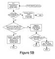
- FIG. 5Aillustrates steps of a proximity search according to an embodiment of the invention.
- FIG. 5Billustrates steps of a delete mover routine according to an embodiment of the invention.
- FIG. 5Cillustrates steps of a delete node from parent routine according to an embodiment of the invention.
- FIG. 5Dillustrates steps of an examine node routine according to an embodiment of the invention.
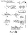
- FIG. 5Eillustrates steps of an insert mover into node routine according to an embodiment of the invention.
- FIG. 5Fillustrates steps of an insert mover routine according to an embodiment of the invention.
- FIG. 5Gillustrates steps of a scan node routine according to an embodiment of the invention.
- FIG. 6illustrates a flow chart of steps for managing moving point data according to an embodiment of the invention.
- FIG. 7illustrates a leaf node of the tree structure populated with location coordinate data.
- FIG. 8illustrates a flow chart of a method for converting a leaf node to a non-leaf node.
- FIG. 9illustrates a flow chart of a method for adding data into a quad-tree structure.
- FIG. 10illustrates graphically the performance over time of the invention and the prior art.
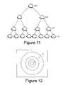
- FIG. 11illustrates a cloud tree according to an embodiment of the invention.
- FIG. 12illustrates concentric clouds with level shown according to an embodiment of the invention.
- FIG. 13illustrates building the cloud tree according to an embodiment of the invention.
- FIG. 14illustrates a spatial view of cloud structure for 2 MUs according to an embodiment of the invention.
- FIG. 15illustrates recursively re-centered clouds according to an embodiment of the invention.
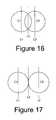
- FIG. 16illustrates initially overlapping clouds according to an embodiment of the invention.
- FIG. 17illustrates clouds re-centered and optimally packed according to an embodiment of the invention.
- FIG. 18illustrates a simulation according to an embodiment of the invention.
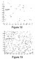
- FIG. 19illustrates a simulation according to an embodiment of the invention.
- FIG. 20Aillustrates a Query Center in Center of Leaf “Cloud” according to an embodiment of the invention.
- FIG. 20Billustrates a Query Center Not in Center of Leaf “Cloud” according to an embodiment of the invention.
- FIG. 21illustrates an Add MU flowchart according to an embodiment of the invention.
- FIG. 22illustrates a Move MU flowchart according to an embodiment of the invention.
- FIG. 23illustrates a Remove MU flowchart according to an embodiment of the invention.
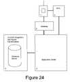
- FIG. 24illustrates a Block diagram of a system according to an embodiment of the invention.
- Exemplary embodiments of the present inventionallow a telecommunications provider to provide MU-to-MU and MU-to-SU services by maintaining accurate and timely location data for individual telecommunications units. For example, a salesman at a tradeshow can use his cell phone to locate and get in touch with potential clients and leads by asking the service to provide users that fit a particular user profile and are proximately located to him. While these exemplary embodiments are shown within the field of mobile telecommunications, it can be readily appreciated by one skilled in the art that the present invention may be used in other fields as well. For example, aspects of the present invention may be used to maintain timely location data for airplanes or automobiles. In fact, this invention may prove useful in any situation where large numbers of data records must be maintained, and certain values within those records are updated frequently.
- One embodiment of the inventionis a system architecture capable of locating a mobile client and discovering or finding other mobile clients who are proximate of a particular mobile user or an arbitrary location.
- a “cloud”refers to a grouping of users, or a recursive grouping of other “clouds”.
- a “cloud”is also descriptive of a region, with no absolute defined borders, that moves and changes shape temporally.
- this embodimentis that any kind of fixed database allocation, such as tessellation, which requires tuning and maintenance, will not scale in an environment incorporating millions of mobile users.
- the inventiondoes not create a fixed tiling scheme. Instead, the technology creates “clouds” that form adaptively in response to user locations. These “clouds” can grow, shrink, and move to accommodate the current number of users in the system.
- a “cloud”is a set of mobile users (or other “clouds”) whose center is the geometric mean of the MUs (or other “clouds”) it contains.
- Cloudsare stored in an N-level tree structure for efficient access and traversal. See FIG. 11 .
- the highest level in the treeis reserved for the root “cloud,” whose area is presumed to cover at least the surface area of the earth (or whatever the desired service coverage area happens to be).
- a “cloud” areais assumed to be circular.
- a “cloud”could be in the shape of any polygon or collection of polygons, not just a circle.
- Each “cloud”can have C child “clouds” contained within it. When viewed as a tree, this means that each “cloud” can have C children. If C equals 2, then the “cloud” tree is binary.
- A(4/3*Pi* R 0 2 )* C n
- R 0is the radius of a “cloud” at level 0
- nis the level.
- the required maximum level “n”is a function of the coverage area and the “cloud” radius at level 0 .
- NLog C ( A/ (4/3*Pi* R 2 ))
- a “leaf cloud”is a “cloud” whose center is determined by the geometric mean of the MU's contained within it (as opposed to mid-level “the invention” whose center is determined by the locations of its child “clouds”).
- a linked list of “clouds”(descending from root to leaf) represents a series of concentric “clouds.”
- the largest “cloud”covers the entire surface of the earth at its root.
- the surface area of the smallest “cloud”(also known as the “leaf cloud”) is predetermined by the depth of the tree, and can be arbitrarily small. “Clouds” are dynamically added to the tree as needed. If there are no users in the system, then only the root “cloud” exists.
- FIG. 12illustrates the concentric regions (“clouds”) created when a first MU is added to the tree. Note that, for simplicity, “clouds” are shown as concentric circles, and only 4 levels are shown here. The first MU added will simply create a linked list from root to leaf. Note how the “clouds” are all centered at the same point, the location of the MU.
- R nSQRT( A n /(4/3*pi))
- FIG. 13shows the branching that occurs as the second user added descends the tree. At level 2 the MU does not fall within the radius of the existing “cloud,” thus branching.
- FIG. 14shows the two separate concentric clouds that exist within the level 3 cloud.
- FIG. 14can be thought of as a “top view” of FIG. 13 . See the left side of the Add Mobile User Flowchart, FIG. 21 .
- “cloud” centersare recursively re-computed upwards to the root.
- the recursionbegins by re-computing the geometric center of the leaf “cloud.” See the right side of the Add Mobile User Flowchart, FIG. 21 .
- This geometric centeris re-computed according to the geometric mean of MUs contained in the leaf “cloud.”
- the parent of each “cloud”then recursively re-computes its center. This allows the clouds to dynamically move to maintain a center at the geometric mean of the mobile users it contains.
- FIG. 15illustrates how “clouds” at level 3 and upwards have re-centered themselves around their children, following the insertion of the user from Los Angeles.
- This re-centeringis to create an adaptive “cloud” tree whose branches always point directly to the true location of the users. This is similar to a tessellated system that always maintains perfect tessellation with variable sized tiles.
- cloudswill maximize system resources: “Clouds” are not created where there are no users.
- each time the position of a user is updated and that user is no longer in the same leaf previously occupiedthe user is removed from the previous “cloud” and reinserted into the tree. See Move Mobile User Flowchart, FIG. 22 .
- a leaf “cloud”contains no MU's
- a recursive deletion of all unnecessary “clouds” from the treeis triggered and clouds re-center. See Remove Mobile User Flowchart, FIG. 23 .
- FIG. 14A very important consideration is that the two “clouds” at level 2 actually overlap, as shown in FIG. 14 . This implies that tile packing is not strictly enforced as with tessellation. Consequently, there is no hard limit on the number of children that any “cloud” can have. However, given a uniform distribution of users, a thought experiment will show that the “clouds” will eventually optimally pack the space of the parent “cloud” in the most efficient manner.
- FIG. 15 and FIG. 16illustrate this concept.
- FIG. 18shows an arbitrary 2 dimensional region with normalized extents.
- the regionbegan with no users. Users joined at simulation time intervals and exited at a random time later.
- the simulationis set so that the service rate is slower than the arrival rate so the region fills (standard queuing theory).
- a normalized “cloud” radius of R 00.5 was chosen. Note that early in the simulation, four “clouds” had quickly formed, as represented by “clouds” centers C 1 , C 2 , C 3 , and C 4 . Users that had joined C 1 are indicated with the number 1 , users that had joined C 2 are indicated with the number 2 , and so on.
- FIG. 19shows the result of the same clouds simulation after running for a longer time period. Notice that C 1 , C 2 , C 3 , C 4 have formed in slightly different regions from the previous observation. Also note that the centers have converged towards (0.25, 0.25), (0.25, 0.75), (0.75, 0.25), and (0.75, 0.75). The centers are actually constantly moving so as to optimally pack the space existing between users and between “clouds.”
- a main attribute of the invetive technology and the “cloud” tree architectureis to provide the fastest possible way to search, identify and locate a mobile user and/or group of mobile users that are proximate to a particular MU or specific geographic point of interest.
- the descentwill simply end at a level where the store is not inside but the nearest to leaf “cloud.”
- This case situationshown in FIG. 20B , shows that MUs inside the “cloud” would generally be on one side of the query center as opposed to surrounding it.
- the applicationdesires a true within distance search of a particular radius, the application simply navigates one level up the tree to re-obtain the list of peer leaf “clouds.” Starting with the nearest peer leaf, the application performs within distance querying inside the peer leaves, discarding MUs that fall outside the radius.
- the new “cloud”may partially or fully overlap the previous “cloud.” Such a scenario may occur at a large sporting event, a popular nightclub district, or a very highly populated region where thousands of users converge on the same area.
- Concurrent “clouds”permit within distance queries to be performed in parallel, allowing the entire density to be within distance queried with the same latency as a single “cloud” query.
- a mobile unit 1(consisting of a processor, internal memory, an input device, and a display device) has radio transmission and reception functionalities (typically a laptop computer, a PDA, or a cellular phone capable of sending and receiving radio waves to exchange information).
- a Mobile Positioning Center (MPC) 2obtains the location data for MUs 1 and publishes this data to other machines.
- An Application Server 3is capable of obtaining and processing data from one or more MPCs.
- a system 4comprises a database with an implementation of the clouds algorithm.
- the systemconsists of at least a processor and permanent and volatile memories. Additional spatial functionalities can be implemented on this system.
- the database and the clouds algorithmcan be stored on the permanent memory, such as on magnetic or optical disk drives.
- a gateway computer 5acts as an intermediary between a MU and the Application Server 3 when an MU requests services or applications from the Application Server. This machine is capable of formatting data in a representation that the MU understands.
- An MUwill send its requests for services to the Gateway computer 5 , which will act on behalf of the MU for service requests and replies to the Application Server.
- the Gateway 5will then format the reply for the MU.
- the inventive principlescomprise a spatial management method and system that is designed to store and maintain moving point data.
- the invention algorithmis efficient, adaptive, and easily implemented independent of a particular RDBMS.
- the inventionis self-optimizing and free of maintenance and tuning.
- the inventioncan scale to store the locations of millions of mobile users and can provide fast within-distance querying regardless of the number of mobile users in the system.
- a computer architectureis provided to locate a MU and find other nearby MUs or SU's in a location-aware telecommunications environment.
- a mobile telecommunications unitis a mobile telecommunications transmitter, transceiver, receiver, or the like, capable of supporting a wireless connection, whether used for data or voice communications. Examples include, but are not limited to, cell phones, pagers, wireless web browsers, personal digital assistants, and laptop, handheld, and wearable computers.
- the operator of the MUis referred to as the user.
- a stationary unit (SU)is any conventional hard-wired telecommunications device or other non-portable device that might otherwise be considered an MU.
- a telecommunications unit (TU)is either a MU or a SU.
- FIG. 1a diagram of a system incorporating aspects of this invention is shown.
- This computer architectureconsists of a moving point server 105 , an API 103 that stores instructions for accessing the moving point data 106 stored on the moving point server 105 , and a database server 101 that stores non-moving point data in a database 102 .
- a database server 101may be provided to store attribute data about MUs in the system.
- an MUmay in this case be a mobile telephone.
- the attribute data stored on the database server 101may include the phone number of the MU, the name of the person who owns the MU, an address for the owner, information about the MU owner's calling plan, the user's business type, or any other information demographically related to that user.
- the data stored in the database server 101is generally static or non-moving point data in that it is not typically updated frequently.
- the database server 101may also run applications that receive data from MUs making requests for data stored in the database server 101 and the moving point server 105 .
- Interface 103Connected to the database server 101 is an interface 103 that contains stored instructions that allow it to communicate with the moving point server 105 .
- Interface 103may be embodied in a variety of forms.
- interface 103may be an API, as is known in the art.
- Interface 103may be a custom piece of software created to bridge the database server and the moving point server. Alternatively, it may be a commercial implementation such as an Informix virtual table interface (VTI).
- Interface 103may store instructions for connecting database server 101 to moving point server 105 .
- Interface 103may be connected to moving point server 105 by a reliable connection 104 such as a TCP socket connection, or some other reliable connection, as is known in the art, such as a serial connection or point-to-point connection.
- Moving point server 105stores moving point data 106 .
- Moving point datais any data ordered in the form of records that are updated frequently.
- Moving point datais made up of identifying data 107 and non-identifying data 108 .
- Identifying data 107is data that uniquely identifies a particular record or object.
- An example of identifying datais a primary key in a database record.
- Non-identifying data 108is data that cannot be used to uniquely identify a record or object.
- a MUchanges locations frequently as it moves or is moved within the telecommunications network.
- Data representing the moving MU's locationis non-identifying data 108 because multiple MU's may be at the same location.
- Data representing the unique identity of that particular MUis identifying data 107 .
- Moving point data 106is generally changed frequently in order to be useful. That is, in the example of the MU moving throughout the telecommunications network, the moving point data 106 (specifically the non-identifying data 108 ) should be current to produce accurate results. In some aspects of the invention, this moving point data 106 consists of objects representing MUs. These objects include identifying data that may consist of a unique object identifier that identifies the MU, and non-identifying data made up of a set of coordinate values that represent the location of that MU.
- the object identifiermay be commonly understandable to each of database server 101 and moving point server 105 .
- the coordinatesmay consist of GPS coordinates, UTM coordinates, or other location identifying data as is known in the art.
- Interface 103may include instructions that allow moving point server 105 to associate moving point data 106 with non-moving point data stored in database server 101 .
- Moving point data 106may be stored on moving point server 105 .
- this datais stored in a datastore in active memory such as DRAM.
- Moving point server 105may be a computer that is separate from the other parts of the computer architecture. This server may, however, also reside on the same machine as interface 103 and database server 102 , provided that its datastore is separable and/or distinct from database 101 that stores the non-moving point data.
- the datastoremay consist of a grouping of tree structures, linked lists, and arrays. However, as one skilled in the art can appreciate, it is possible to use other kinds of data storage techniques and combinations of data structures in order to efficiently keep the moving point data in active memory.
- the moving point serverholds a datastore comprising at least three data structures.
- the first data structureis used to maintain an index of objects based upon their identifying data 107 .
- the first data structurestores identifying data 107 .
- This identifying datamay be an object identifier or a key value in a database.
- the second data structuremay be used to store non-identifying data 108 .
- a purpose of the second data structureis to store the non-identifying data in such a way that for a given object record (for example an MU), those object records with similar (but not necessarily identical) non-identifying data can be easily located and referenced.
- the second data structureis a quad-tree that stores non-identifying data 107 in the form of location coordinate pairs.
- the third data structuremay be used for tying the first and second data structures together. There may, however, be several data structures that tie the first and second data structure together. In one embodiment the third set of data structures consist of linked lists of objects. Both identifying data 107 and non-identifying data 108 may be stored in these linked lists of objects.
- datastore 106contains a first data structure in the form of an object handler 202 .
- Object handler 202may be an array, a linked list, or some other data structure as is known in the art.
- Object handler 202may be made up of individual cells 203 .
- each cell 203 in the object handlerrepresents an MU that is already stored in the system.
- FIG. 2Aillustrates an example of this array.
- Each cellmay contain an object identifier 211 that is used to relate this data to a particular MU record on database server 102 .
- Each cellmay also contain an object pointer 212 to an object descriptor record that is part of the second type of data structure described above.
- This object identifiermight not contain the same identifying value as its related record on the database server.
- the object identifierneed only provide enough information so that the system, when communicating between database server 102 and moving point server 105 , may ascertain that a cell 203 in object handler 202 is referring to a particular MU record stored on database server 102 .
- tree structure 300may be used to store location coordinates or other non-identifying data.
- the tree structure 300may store identifying data as well in addition to the non-identifying data.
- Each node in the treemay have as few as two branches (also called children), or as many as several dozen (or more). Data may be stored in leaf nodes.
- the tree's starting pointis referred to as the root.
- tree structure 300is a quad-tree.
- Quad-tree structure 300has root node 302 . If root node 302 is the only node in the tree, then that node is also a leaf node and stores moving point data. As the tree grows, non-leaf nodes are created, as will be described below.
- leaf nodesdiffer from non-leaf nodes in that they may contain a data structure (or container) in which may be stored references to object descriptor records.
- the container 402 within leaf node 400may be an array, a linked list, or some other data structure known in the art.
- container 402is an array of pointers 404 to object descriptor records 204 stored on moving point server 105 . This array may be limited in size, i.e. it may contain a limited number of pointer records.
- An advantage of the inventive systemis the ability for the architecture to quickly grow, yet maintain a stable rate of performance throughout that growth. Moreover, as the number of objects on the moving point server increases, the granularity of proximity searches continually improves.
- the datastore located on the moving point serveris empty.
- the object handlerhas been created but has no records in it, since no records are in the object handler there are no object descriptor records, and the quad-tree has only a root record.
- the location-aware telecommunications networkis set up so that it receives location data from MUs every fifteen minutes (or other predetermined amount of time).
- the location measurements received by the networkwill have a specific granularity, or degree of physical accuracy, e.g., location specificity to within 100 square feet.
- location specificitye.g., location specificity to within 100 square feet.
- One aspect of the present inventionalleviates this need by not creating a location record until a location appears in the system (i.e., an MU report being at that location).
- FIGS. 7 , 8 , and 9The process of changing a leaf node to a non-leaf node as a result of a filled container is illustrated in FIGS. 7 , 8 , and 9 .
- FIG. 7illustrates such a leaf node 702 , its container 704 populated with 9 record entries of X/Y coordinates. These entries may be actual coordinates as shown in FIG. 7 , or they may be pointers to object descriptor records that contain X/Y coordinates.
- a control application in the moving point servertraversed the tree in order to find the proper leaf node in which the coordinate data should be inserted.
- the nodeis checked to determine whether it is a leaf or non-leaf node in step 904 . If the encountered node is a leaf node, then another determination must be made in step 906 : is the node container full? If not, then in step 908 the new coordinates A/B are inserted into the node container and a pointer is created that references the object descriptor record that corresponds to these coordinates.
- each coordinate pair that was in the leaf node containeris added back into the tree by calling this same insertion routine starting at step 900 .
- the A/B valuesmust be compared to the X/Y coordinate pair in the encountered non-leaf node (step 914 ).
- each non-leaf node 304has four branches which lead to child nodes. To illustrate, assume that we call the branches Branch_ 1 , Branch_ 2 , Branch_ 3 , and Branch_ 4 . The following formula will dictate which of the four possible child nodes will be followed:
- step 916the process repeats itself by going back to step 902 where it encounters a tree node.
- the received location coordinateshave traversed the tree and found a leaf node 702 .
- the leaf node container 704is already full.
- the current leaf node 702may be converted to a non-leaf node, spawning four new leaf nodes, in order to create more space in the tree.
- the median values 708 of the X coordinates and the Y coordinates found in container 704may be used as the demarcation points for creating the new leaf nodes. Observing the X/Y data values found in the leaf node container 704 , the median X/Y values may be easily determined. In this example, the (median X value is 128.2, and the median Y value is 19.6).
- Leaf node 702is converted to non-leaf node 802 , with an X value of 128.2 and a Y value of 19.6.
- Each of the nine X/Y coordinates found in leaf node container 704may be reinserted into the tree, as shown in step 912 and is placed in one of the four new leaf nodes. This reinsertion is accomplished by taking each separate X/Y coordinate and applying the insertion routine described in FIG. 9 .
- object descriptor record 204is a record held in computer memory that holds information about the object to which it refers.
- the objects described by object descriptor recordsrepresent MUs. They may, however, also be SU's or some other telecommunications unit.
- Object descriptor record 204may be a record in an array, or a node of a linked list, or in some other data structure known in the art. In one embodiment (shown in FIG. 2B ), object descriptor records are stored nodes of a linked list.
- Each object descriptor record 204has a field in which to store an object identifier 220 (object_ID), a field or fields in which location coordinates may be held, for example X object — ID 221 and Y object — ID 222 , and a leaf pointer 223 that points to a leaf node 400 in a tree structure 300 (see FIG. 3 ).
- the leaf pointer 223need not be part of the object descriptor record. It may in other embodiments of the present invention be part of the linked list node(s).
- only the record in the first node in the linked listwill have a leaf pointer 223 to the leaf node while the other records have NULL leaf pointers, in other embodiments, however, multiple records in the linked list may have a leaf pointer 223 to the leaf node 206 in the tree structure 300 .
- Object descriptor records with identical location coordinatesmay be placed together in linked lists. Such a placement allows the system to easily locate all object descriptor records 204 with identical location coordinates by locating just a single object descriptor with those same coordinates. This exact process will be further described below.
- Each node containing an object descriptor record 204may contain a head pointer field 207 and a tail pointer field 208 in order to provide two-way linking with other object descriptor records having similar or identical location coordinates.
- new MUsi.e. those previously unknown to the moving point server
- This moving point datamay be added to the datastore.
- a new cell 203may be allocated for this MU in object handler 202 .
- the object identifier for that MUis inserted into that cell.
- An object descriptor recordis created, and is referenced by cell 203 that was created to store the record identifier.
- This referencemay take the form of a record pointer, but it is well-understood in the art that the reference might be another method of locating data in memory.
- the object descriptor recordmay contain at least an object identifier and a set of location coordinates.
- the object descriptoris not limited to such data. It may be appropriate to include other data such as data indicative of one or more particular preference(s) associated with the MU.
- Object descriptor record 204may be placed into datastore 106 in the same linked list as other object descriptor records with identical or near identical location coordinates. If no similar location already exist, then it is placed in its own linked list as the only node. Placing the object descriptor records in linked lists allows the system to easily determine those MUs which are similarly located. Moreover, the utilization of the linked lists also prevents the unnecessary population of the tree structure. For example, consider a location-aware network that is capable of recognizing measurements to a granularity of 100 square feet. Those MUs whose object coordinate measurements are identical (i.e. within the same 100 square foot space), may be represented in object descriptor records that are placed together in a linked list 209 or some other type data structure (e.g.
- moving point server 105receives moving point data in the form of location coordinates and an object identifier for an MU over reliable connection 104 from interface 103 that communicates with database server 101 . If reference to the MU is not already stored in the object handler 202 of the datastore then this entry constitutes new moving point data and an object handler cell 203 is populated with the received moving point data as described above. However, if upon receiving moving point data from interface 103 , the system discovers that there is already a cell in the object handler having an identical object identifier to that received, then this MU is already in the datastore and must be updated rather than added. The system may discover the existence of the identical object identifier by searching each cell 203 in object handler 202 for the same coordinates as received from the 103 .
- moving point server 105updates, if necessary, the existing data that represents the MU specified in the object identifier.
- the received location coordinatesare compared to the existing location coordinates in the object descriptor record 204 that already exists for that particular MU. If the location coordinates are the same in the received moving point data and the current object descriptor record, then no changes are necessary, because the location of the MU has not changed. If, however, the compared values are different, the object descriptor record may be modified in one of three ways, dependant on the situation created by the object descriptor record's placement in linked list 209 .
- the modificationconsists of deleting the object descriptor record and any related reference to it in the tree structure, and then replacing the deleted object descriptor record with the new moving point data by inserting the new moving point data into the datastore as described above.
- the modification to the datastoremay consist of actually changing record values rather than deleting and replacing them.
- the first situationinvolves the instance where the object descriptor record is not part of linked list 210 .
- the object descriptor recorddoes not share identical coordinates with any other object descriptor record. It does, however, necessarily have a leaf node 400 that it references in tree structure 300 .
- a record in container 402 stored in that same leaf node 400references object descriptor record 204 via a pointer 404 or some other reference variable.
- the record in container 402is removed along with its pointer reference 404 to object descriptor record 204 .
- Object descriptor record 204is then deleted, and a new object descriptor record is created using the process described previously with the new location data.
- object descriptor record 204is part of linked list 209 , but not at the head of the linked list, that record may be removed from the linked list and a new object descriptor record based upon the new location coordinates is created using the process previously described. Because, in one embodiment, no record in the tree structure points to a non-head node of a linked list 209 , no changes may be necessary to the tree structure.
- a third situationinvolves instances where the modified location coordinates are received for an object descriptor record that is at the head of a linked list of other object descriptor records.
- the object descriptor record 204should be deleted from the linked list and its corresponding location pointer reference 404 in the leaf node of the tree modified to point to the first remaining item in the linked list 209 .
- This change modification of the pointer referencemay be accomplished through the use of temporary pointer variables or some other technique known in the art.
- a proximity searchoccurs when the moving point server receives a request for the set of MU's that are proximately located to a given location. See FIG. 5 .
- the moving point server 105first searches the tree structure 300 for a leaf node 400 that encapsulates the received coordinates. The tree structure is searched using the method described above for inserting a coordinate pair into the tree.
- Object descriptor records 204 pointed to by container array pointers 404are retrieved and sent back to the interface 103 .
- the interface 103then will convert the data into a format that can be read by a database query language such as SQL or some other language known in the art. Once this conversion takes place, the database server may access the data set as it would a typical datasource and return the result set to the MU making the original request.
- a database query languagesuch as SQL or some other language known in the art.
- FIGS. 5A–5Gillustrate steps of subroutines that may be used in one or more of the above described embodiments.
- One or more of the illustrated subroutinesmay be used in each embodiment.
- Other subroutinesmay also be used, and some subroutines may be combined and performed in a single subroutine instead of separately.
- the invention as described hereinprovides a significant improvement over spatial solutions currently known in the art.
- FIG. 10Ain benchmark tests conducted at Sun Benchmark Center, aspects of this invention were able to complete more than 800 transactions per second without diminished performance over an extended period of time.
- a spatial solution known in the artwas found to complete less than 40 transactions per second.
- performanceimmediately degraded and came to a halt around 100,000 transactions.
Landscapes
- Engineering & Computer Science (AREA)
- Computer Networks & Wireless Communication (AREA)
- Signal Processing (AREA)
- Mobile Radio Communication Systems (AREA)
- Information Retrieval, Db Structures And Fs Structures Therefor (AREA)
Abstract
Description
An=(4/3*Pi*R02)*Cn
N=LogC(A/(4/3*Pi*R2))
Rn=SQRT(An/(4/3*pi))
Claims (16)
Priority Applications (5)
| Application Number | Priority Date | Filing Date | Title |
|---|---|---|---|
| US10/012,367US7010308B2 (en) | 2000-12-13 | 2001-12-12 | Managing and querying moving point data |
| AU2002255444AAU2002255444A1 (en) | 2000-12-13 | 2001-12-13 | Managing and querying moving point data |
| PCT/US2001/047952WO2002069075A2 (en) | 2000-12-13 | 2001-12-13 | Managing and querying moving point data |
| US10/198,622US7813741B2 (en) | 2001-07-18 | 2002-07-17 | System and method for initiating responses to location-based events |
| PCT/US2002/022709WO2003009610A1 (en) | 2001-07-18 | 2002-07-17 | System and method for initiating responses to location-based events |
Applications Claiming Priority (2)
| Application Number | Priority Date | Filing Date | Title |
|---|---|---|---|
| US25492200P | 2000-12-13 | 2000-12-13 | |
| US10/012,367US7010308B2 (en) | 2000-12-13 | 2001-12-12 | Managing and querying moving point data |
Related Child Applications (1)
| Application Number | Title | Priority Date | Filing Date |
|---|---|---|---|
| US10/198,622Continuation-In-PartUS7813741B2 (en) | 2001-07-18 | 2002-07-17 | System and method for initiating responses to location-based events |
Publications (2)
| Publication Number | Publication Date |
|---|---|
| US20020151315A1 US20020151315A1 (en) | 2002-10-17 |
| US7010308B2true US7010308B2 (en) | 2006-03-07 |
Family
ID=26683474
Family Applications (1)
| Application Number | Title | Priority Date | Filing Date |
|---|---|---|---|
| US10/012,367Expired - LifetimeUS7010308B2 (en) | 2000-12-13 | 2001-12-12 | Managing and querying moving point data |
Country Status (3)
| Country | Link |
|---|---|
| US (1) | US7010308B2 (en) |
| AU (1) | AU2002255444A1 (en) |
| WO (1) | WO2002069075A2 (en) |
Cited By (11)
| Publication number | Priority date | Publication date | Assignee | Title |
|---|---|---|---|---|
| US20040203845A1 (en)* | 2002-03-22 | 2004-10-14 | Lal Amrish K. | Method and system for associating location specific data with data in a mobile database |
| US20060009152A1 (en)* | 2004-07-06 | 2006-01-12 | International Business Machines Corporation | Method and application for automatic tracking of mobile devices for computer network processor systems |
| US20060039272A1 (en)* | 2004-08-23 | 2006-02-23 | Divaydeep Sikri | Multi-band wideband transmission methods and apparatus having improved user capacity |
| US20060058958A1 (en)* | 2004-09-14 | 2006-03-16 | Nicholas Galbreath | Proximity search methods using tiles to represent geographical zones |
| US20090171779A1 (en)* | 2007-12-28 | 2009-07-02 | Telenav, Inc. | Mobile Advertisement and Rating System |
| US7769632B2 (en) | 1999-12-17 | 2010-08-03 | Promovu, Inc. | System for selectively communicating promotional information to a person |
| US8060109B2 (en) | 1997-08-04 | 2011-11-15 | Enovsys Llc | Authorized location reporting mobile communication system |
| US9013267B2 (en) | 2010-08-24 | 2015-04-21 | Rhonda Enterprises, Llc | Systems and methods for position-based loaning of electronic documents to electronic device users |
| US20150227553A1 (en)* | 2013-04-09 | 2015-08-13 | Nec Europe Ltd. | Method for generating a dataset structure for location-based services and method and system for providing location-based services to a mobile device |
| US9584960B1 (en) | 2005-04-04 | 2017-02-28 | X One, Inc. | Rendez vous management using mobile phones or other mobile devices |
| US10735984B2 (en) | 2017-12-29 | 2020-08-04 | Dish Network L.L.C. | Systems and methods for identifying user density from network data |
Families Citing this family (38)
| Publication number | Priority date | Publication date | Assignee | Title |
|---|---|---|---|---|
| US6879980B1 (en)* | 2001-06-29 | 2005-04-12 | Oracle International Corporation | Nearest neighbor query processing in a linear quadtree spatial index |
| US7152071B2 (en)* | 2002-05-01 | 2006-12-19 | Sun Microsystems, Inc. | Shape-based geometric database and methods and systems for construction and use thereof |
| JP4305092B2 (en)* | 2002-08-14 | 2009-07-29 | ソニー株式会社 | Information processing apparatus, data communication system and method, and computer program |
| US7292846B2 (en)* | 2003-02-28 | 2007-11-06 | Nokia Corporation | Apparatus, and associated method, for retrieving mobile-node device management tree information |
| JP2007512765A (en)* | 2003-11-21 | 2007-05-17 | クゥアルコム・インコーポレイテッド | Estimating the position of a wireless mobile device with respect to one or more base stations |
| US7576754B1 (en) | 2005-10-27 | 2009-08-18 | Google Inc. | System and method for identifying bounds of a geographical area |
| US7983949B1 (en)* | 2005-10-27 | 2011-07-19 | Google Inc. | System and method for selecting targeted information for serving with a map view |
| US7595725B1 (en) | 2005-10-27 | 2009-09-29 | Google Inc. | System and method for identifying geographical areas that significantly overlap a map view |
| US7751346B2 (en)* | 2005-12-01 | 2010-07-06 | Electronics And Telecommunications Research Institute | Apparatus for searching TCP and UDP sockets |
| US8103519B2 (en) | 2006-01-30 | 2012-01-24 | Hoozware, Inc. | System for marketing campaign specification and secure digital coupon redemption |
| US9105039B2 (en) | 2006-01-30 | 2015-08-11 | Groupon, Inc. | System and method for providing mobile alerts to members of a social network |
| WO2007090133A2 (en) | 2006-01-30 | 2007-08-09 | Kramer Jame F | System for providing a service to venues where people aggregate |
| US20110093340A1 (en) | 2006-01-30 | 2011-04-21 | Hoozware, Inc. | System for providing a service to venues where people perform transactions |
| US7788188B2 (en) | 2006-01-30 | 2010-08-31 | Hoozware, Inc. | System for providing a service to venues where people aggregate |
| US7444343B2 (en)* | 2006-03-31 | 2008-10-28 | Microsoft Corporation | Hybrid location and keyword index |
| US7945386B2 (en)* | 2006-08-25 | 2011-05-17 | Mitac International Corporation | Rerouting in vehicle navigation systems |
| US7650431B2 (en)* | 2006-08-28 | 2010-01-19 | Microsoft Corporation | Serving locally relevant advertisements |
| US20080139181A1 (en)* | 2006-12-08 | 2008-06-12 | Magellan Navigation, Inc. | Methods and apparatus for measuring the effectiveness of advertisements presented on a mobile navigation device |
| US7692655B2 (en)* | 2007-02-16 | 2010-04-06 | Mitac International Corporation | Apparatus and method of generating curved baseline for map labeling |
| US7783417B2 (en)* | 2007-03-09 | 2010-08-24 | Mitac International Corporation | Methods and apparatus for determining a route having an estimated minimum fuel usage for a vehicle |
| US7835863B2 (en)* | 2007-04-18 | 2010-11-16 | Mitac International Corporation | Method and system for navigation using GPS velocity vector |
| US8078641B2 (en)* | 2007-04-25 | 2011-12-13 | Mitac International Corporation | Adjusting spatial operations based on map density |
| US7882102B2 (en)* | 2007-09-10 | 2011-02-01 | Mitac International Corporation | Nearest-neighbor geographic search |
| US8554475B2 (en) | 2007-10-01 | 2013-10-08 | Mitac International Corporation | Static and dynamic contours |
| US20090138190A1 (en)* | 2007-11-26 | 2009-05-28 | Magellan Navigation, Inc. | System and Method of Providing Traffic Data to a Mobile Device |
| US20090171584A1 (en)* | 2007-12-31 | 2009-07-02 | Magellan Navigation, Inc. | System and Method for Accessing a Navigation System |
| US20090182498A1 (en)* | 2008-01-11 | 2009-07-16 | Magellan Navigation, Inc. | Systems and Methods to Provide Navigational Assistance Using an Online Social Network |
| US8700314B2 (en)* | 2008-01-18 | 2014-04-15 | Mitac International Corporation | Method and apparatus to search for local parking |
| US8498808B2 (en)* | 2008-01-18 | 2013-07-30 | Mitac International Corp. | Method and apparatus for hybrid routing using breadcrumb paths |
| US8290703B2 (en)* | 2008-01-18 | 2012-10-16 | Mitac International Corporation | Method and apparatus for access point recording using a position device |
| US20100035631A1 (en)* | 2008-08-07 | 2010-02-11 | Magellan Navigation, Inc. | Systems and Methods to Record and Present a Trip |
| US8249804B2 (en)* | 2008-08-20 | 2012-08-21 | Mitac International Corporation | Systems and methods for smart city search |
| US8219317B2 (en)* | 2008-09-22 | 2012-07-10 | Mitac International Corporation | Route navigation via a proximity point |
| US9235842B2 (en) | 2009-03-02 | 2016-01-12 | Groupon, Inc. | Method for providing information to contacts without being given contact data |
| US9501526B2 (en)* | 2013-04-17 | 2016-11-22 | Excalibur Ip, Llc | Efficient database searching |
| US9934249B2 (en)* | 2014-06-03 | 2018-04-03 | Conduent Business Machines Services, Llc | Systems and methods for context-aware and personalized access to visualizations of road events |
| US10839598B2 (en)* | 2016-07-26 | 2020-11-17 | Hewlett-Packard Development Company, L.P. | Indexing voxels for 3D printing |
| CN113971182B (en)* | 2021-12-23 | 2022-03-15 | 北京蓝莓时节科技有限公司 | LBS distributed service system, method and storage medium |
Citations (76)
| Publication number | Priority date | Publication date | Assignee | Title |
|---|---|---|---|---|
| US5043736A (en) | 1990-07-27 | 1991-08-27 | Cae-Link Corporation | Cellular position locating system |
| US5295180A (en) | 1992-04-08 | 1994-03-15 | U S West Newvector Group, Inc. | Cellular telephone zone system |
| EP0708571A2 (en) | 1994-10-17 | 1996-04-24 | AT&T Corp. | Method and system for distributed control in wireless cellular and personal communication systems |
| US5539922A (en)* | 1992-01-03 | 1996-07-23 | Motorola, Inc. | Multiple tree hierarchical portable communication system and method |
| US5568153A (en) | 1995-05-30 | 1996-10-22 | Telefonaktiebolaget Lm Ericsson | Individually defined personal home area for subscribers in a cellular telecommunications network |
| WO1997013387A1 (en) | 1995-10-05 | 1997-04-10 | Telia Ab | Identification of home area in a mobile telecommunication system |
| WO1997014054A1 (en) | 1995-10-09 | 1997-04-17 | Snaptrack, Inc. | Client-server-based remote locator device |
| WO1997016934A1 (en) | 1995-10-31 | 1997-05-09 | Jarlab Ab | Telecommunications system |
| WO1997041654A1 (en) | 1996-04-29 | 1997-11-06 | Telefonaktiebolaget Lm Ericsson | Telecommunications information dissemination system |
| WO1998003025A1 (en) | 1996-07-16 | 1998-01-22 | Motorola Inc. | Display of geographic locations with correlated signal quality measurements |
| US5758288A (en) | 1992-04-08 | 1998-05-26 | Dunn; Michael Jeffrey | Signal time of arrival position determining method for calculating cellular telephone billing charges |
| US5761648A (en) | 1995-07-25 | 1998-06-02 | Interactive Coupon Network | Interactive marketing network and process using electronic certificates |
| US5774802A (en) | 1996-04-10 | 1998-06-30 | Motorola Inc. | Apparatus and method for billing in a wireless communication system |
| WO1998036585A2 (en) | 1997-02-18 | 1998-08-20 | Northern Telecom Inc. | Sponsored call and cell service |
| US5852775A (en) | 1996-09-12 | 1998-12-22 | Earthweb, Inc. | Cellular telephone advertising system |
| US5873040A (en) | 1996-08-13 | 1999-02-16 | International Business Machines Corporation | Wireless 911 emergency location |
| US5884272A (en) | 1996-09-06 | 1999-03-16 | Walker Asset Management Limited Partnership | Method and system for establishing and maintaining user-controlled anonymous communications |
| US5918180A (en) | 1995-12-22 | 1999-06-29 | Dimino; Michael | Telephone operable global tracking system for vehicles |
| WO1999033199A1 (en) | 1997-12-19 | 1999-07-01 | Telefonaktiebolaget Lm Ericsson (Publ) | Method and arrangement in a communication network |
| WO1999033293A1 (en) | 1997-12-23 | 1999-07-01 | Global Mobility Systems, Inc. | System and method for controlling personal information and information delivery to and from a telecommunications device |
| US5953400A (en) | 1996-07-18 | 1999-09-14 | At&T Corp. | Communication system for a closed-user group |
| US5963864A (en) | 1996-05-31 | 1999-10-05 | Bellsouth Intellectual Property Management Corporation | Method and system for automatically connecting telephone calls to multiple devices having different directory numbers |
| US5966696A (en) | 1998-04-14 | 1999-10-12 | Infovation | System for tracking consumer exposure and for exposing consumers to different advertisements |
| US5974393A (en) | 1997-01-17 | 1999-10-26 | Mccullough; Robert K. | Automatic customer number paging system |
| WO1999056144A1 (en) | 1998-04-28 | 1999-11-04 | Snaptrack, Inc. | Method and apparatus for providing location-based information via a computer network |
| US5982281A (en) | 1998-05-02 | 1999-11-09 | Pro Tech Monitoring, Inc. | Offender and victim collision avoidance and advanced warning system |
| US5995015A (en) | 1989-05-16 | 1999-11-30 | Electronic Advertising Solutions Innovators, Inc. D/B/A Easi, Inc. | Remote electronic information display system for retail facility |
| WO1999066757A1 (en) | 1998-06-16 | 1999-12-23 | Ericsson Inc. | System and method for location-based group services |
| US6018699A (en) | 1996-06-04 | 2000-01-25 | Baron Services, Inc. | Systems and methods for distributing real-time site specific weather information |
| WO2000004730A1 (en) | 1998-07-20 | 2000-01-27 | Signalsoft Corp. | Subscriber delivered location-based services |
| US6041358A (en)* | 1996-11-12 | 2000-03-21 | Industrial Technology Research Inst. | Method for maintaining virtual local area networks with mobile terminals in an ATM network |
| US6044261A (en) | 1997-03-19 | 2000-03-28 | Ericsson, Inc. | Multiple home zone areas within a mobile telecommunications network |
| WO2000019344A2 (en) | 1998-09-25 | 2000-04-06 | L.I.M.S. (Management Systems) 1993 Ltd. | Method and system of interlinking |
| WO2000022860A1 (en) | 1998-10-12 | 2000-04-20 | Janus Friis Degnbol | A method and a system for transmitting data between units |
| US6055434A (en) | 1997-02-11 | 2000-04-25 | Ericsson Inc. | Method and system for locating a mobile station within a mobile telecommunications network |
| US6061561A (en) | 1996-10-11 | 2000-05-09 | Nokia Mobile Phones Limited | Cellular communication system providing cell transmitter location information |
| US6061681A (en) | 1997-06-30 | 2000-05-09 | Movo Media, Inc. | On-line dating service for locating and matching people based on user-selected search criteria |
| US6060995A (en) | 1997-02-19 | 2000-05-09 | Sony Corporation | Nightlife information pager |
| US6067045A (en) | 1998-09-01 | 2000-05-23 | Hughes Electronics Corporation | Communication network initialization apparatus and method for fast GPS-based positioning |
| US6067356A (en) | 1997-09-20 | 2000-05-23 | Alcatel | Method of routing emergency calls |
| US6073138A (en) | 1998-06-11 | 2000-06-06 | Boardwalk A.G. | System, method, and computer program product for providing relational patterns between entities |
| WO2000035216A1 (en) | 1998-12-10 | 2000-06-15 | Leap Wireless International, Inc. | System and method for providing targeted messages based on wireless mobile location |
| WO2000040038A2 (en) | 1998-12-23 | 2000-07-06 | American Calcar Inc. | Technique for effective communications with, and provision of global positioning system (gps) based advertising information to, automobiles |
| US6091956A (en) | 1997-06-12 | 2000-07-18 | Hollenberg; Dennis D. | Situation information system |
| WO2000051333A1 (en) | 1999-02-22 | 2000-08-31 | Koninklijke Kpn N.V. | Access-point-dependent rate fixing of telecommunication links |
| US6119014A (en) | 1998-04-01 | 2000-09-12 | Ericsson Inc. | System and method for displaying short messages depending upon location, priority, and user-defined indicators |
| WO2000062564A1 (en) | 1999-04-12 | 2000-10-19 | Qualcomm Incorporated | System and method for distributing advertising and gathering information in a wireless communication network |
| US6157841A (en) | 1997-09-18 | 2000-12-05 | At&T Corp. | Cellular phone network that provides location-based information |
| US6166685A (en) | 1998-11-19 | 2000-12-26 | Qualcomm Incorporated | Wireless user position update using infrastructure measurements |
| WO2001015480A1 (en) | 1999-08-24 | 2001-03-01 | Nokia Corporation | Mobile communications subscriber profile matching system |
| US6208866B1 (en) | 1998-12-30 | 2001-03-27 | Ericsson Inc. | System and method for location-based marketing to mobile stations within a cellular network |
| WO2001024551A1 (en) | 1999-09-29 | 2001-04-05 | Swisscom Mobile Ag | Method for finding members of a common interest group |
| WO2001026408A1 (en) | 1999-10-05 | 2001-04-12 | Real Venture Group Ab | Method and system for assisting mobile telecommunication terminal users |
| US6233506B1 (en) | 1997-01-28 | 2001-05-15 | American Calcar Inc. | Technique for effectively locating an object |
| US6286005B1 (en) | 1998-03-11 | 2001-09-04 | Cannon Holdings, L.L.C. | Method and apparatus for analyzing data and advertising optimization |
| US6292672B1 (en) | 1998-10-29 | 2001-09-18 | Avaya Technology Corp. | Call pickup group controlled by wireless terminals |
| US6292743B1 (en) | 1999-01-06 | 2001-09-18 | Infogation Corporation | Mobile navigation system |
| US20010027111A1 (en) | 2000-03-30 | 2001-10-04 | Ddi Corporation | Group communication system for mobile terminals |
| US6332127B1 (en) | 1999-01-28 | 2001-12-18 | International Business Machines Corporation | Systems, methods and computer program products for providing time and location specific advertising via the internet |
| US6360102B1 (en) | 1998-09-10 | 2002-03-19 | Ericsson Inc. | System and method for defining a subscriber location privacy profile |
| US6370539B1 (en)* | 1996-10-25 | 2002-04-09 | Navigation Technologies Corporation | Interface layer for navigation system |
| US6377793B1 (en) | 2000-12-06 | 2002-04-23 | Xybernaut Corporation | System and method of accessing and recording messages at coordinate way points |
| US6381465B1 (en) | 1999-08-27 | 2002-04-30 | Leap Wireless International, Inc. | System and method for attaching an advertisement to an SMS message for wireless transmission |
| US6397057B1 (en) | 1995-06-07 | 2002-05-28 | Ewireless, Inc. | System and method of providing advertising information to a subscriber through a wireless device |
| US6400956B1 (en) | 1999-11-15 | 2002-06-04 | Lucent Technologies Inc. | Method and apparatus for a wireless telecommunication system that provides location-based action services |
| US6411891B1 (en) | 1997-03-10 | 2002-06-25 | Global Research Systems, Inc. | Advance notification system and method utilizing user-definable notification time periods |
| US6442391B1 (en) | 1997-05-16 | 2002-08-27 | Telefonaktiebolaget L M Ericsson (Publ) | Location security for a subscriber unit in a telecommunication system by denying a parties' location request |
| US6463180B1 (en)* | 1998-04-07 | 2002-10-08 | Autodesk, Inc. | Spatial index compression through spatial subdivision encoding |
| US6484148B1 (en) | 2000-02-19 | 2002-11-19 | John E. Boyd | Electronic advertising device and method of using the same |
| US6505046B1 (en) | 1997-11-19 | 2003-01-07 | Nortel Networks Limited | Method and apparatus for distributing location-based messages in a wireless communication network |
| US6594483B2 (en) | 2001-05-15 | 2003-07-15 | Nokia Corporation | System and method for location based web services |
| US6647257B2 (en) | 1998-01-21 | 2003-11-11 | Leap Wireless International, Inc. | System and method for providing targeted messages based on wireless mobile location |
| US6650902B1 (en)* | 1999-11-15 | 2003-11-18 | Lucent Technologies Inc. | Method and apparatus for wireless telecommunications system that provides location-based information delivery to a wireless mobile unit |
| US6750883B1 (en)* | 2000-04-05 | 2004-06-15 | Microsoft Corporation | Identity-based context aware computing systems and methods |
| US6826598B1 (en)* | 1998-05-05 | 2004-11-30 | British Telecommunications Public Limited Company | Storage and retrieval of location based information in a distributed network of data storage devices |
| US6836667B1 (en) | 2000-09-19 | 2004-12-28 | Lucent Technologies Inc. | Method and apparatus for a wireless telecommunication system that provides location-based messages |
- 2001
- 2001-12-12USUS10/012,367patent/US7010308B2/ennot_activeExpired - Lifetime
- 2001-12-13WOPCT/US2001/047952patent/WO2002069075A2/ennot_activeApplication Discontinuation
- 2001-12-13AUAU2002255444Apatent/AU2002255444A1/ennot_activeAbandoned
Patent Citations (79)
| Publication number | Priority date | Publication date | Assignee | Title |
|---|---|---|---|---|
| US5995015A (en) | 1989-05-16 | 1999-11-30 | Electronic Advertising Solutions Innovators, Inc. D/B/A Easi, Inc. | Remote electronic information display system for retail facility |
| US5043736B1 (en) | 1990-07-27 | 1994-09-06 | Cae Link Corp | Cellular position location system |
| US5043736A (en) | 1990-07-27 | 1991-08-27 | Cae-Link Corporation | Cellular position locating system |
| US5539922A (en)* | 1992-01-03 | 1996-07-23 | Motorola, Inc. | Multiple tree hierarchical portable communication system and method |
| US5758288A (en) | 1992-04-08 | 1998-05-26 | Dunn; Michael Jeffrey | Signal time of arrival position determining method for calculating cellular telephone billing charges |
| US5295180A (en) | 1992-04-08 | 1994-03-15 | U S West Newvector Group, Inc. | Cellular telephone zone system |
| EP0708571A2 (en) | 1994-10-17 | 1996-04-24 | AT&T Corp. | Method and system for distributed control in wireless cellular and personal communication systems |
| US5568153A (en) | 1995-05-30 | 1996-10-22 | Telefonaktiebolaget Lm Ericsson | Individually defined personal home area for subscribers in a cellular telecommunications network |
| US6397057B1 (en) | 1995-06-07 | 2002-05-28 | Ewireless, Inc. | System and method of providing advertising information to a subscriber through a wireless device |
| US5761648A (en) | 1995-07-25 | 1998-06-02 | Interactive Coupon Network | Interactive marketing network and process using electronic certificates |
| WO1997013387A1 (en) | 1995-10-05 | 1997-04-10 | Telia Ab | Identification of home area in a mobile telecommunication system |
| WO1997014054A1 (en) | 1995-10-09 | 1997-04-17 | Snaptrack, Inc. | Client-server-based remote locator device |
| WO1997016934A1 (en) | 1995-10-31 | 1997-05-09 | Jarlab Ab | Telecommunications system |
| US5918180A (en) | 1995-12-22 | 1999-06-29 | Dimino; Michael | Telephone operable global tracking system for vehicles |
| US5774802A (en) | 1996-04-10 | 1998-06-30 | Motorola Inc. | Apparatus and method for billing in a wireless communication system |
| WO1997041654A1 (en) | 1996-04-29 | 1997-11-06 | Telefonaktiebolaget Lm Ericsson | Telecommunications information dissemination system |
| US5963864A (en) | 1996-05-31 | 1999-10-05 | Bellsouth Intellectual Property Management Corporation | Method and system for automatically connecting telephone calls to multiple devices having different directory numbers |
| US6018699A (en) | 1996-06-04 | 2000-01-25 | Baron Services, Inc. | Systems and methods for distributing real-time site specific weather information |
| WO1998003025A1 (en) | 1996-07-16 | 1998-01-22 | Motorola Inc. | Display of geographic locations with correlated signal quality measurements |
| US5953400A (en) | 1996-07-18 | 1999-09-14 | At&T Corp. | Communication system for a closed-user group |
| US5873040A (en) | 1996-08-13 | 1999-02-16 | International Business Machines Corporation | Wireless 911 emergency location |
| US5884272A (en) | 1996-09-06 | 1999-03-16 | Walker Asset Management Limited Partnership | Method and system for establishing and maintaining user-controlled anonymous communications |
| US5852775A (en) | 1996-09-12 | 1998-12-22 | Earthweb, Inc. | Cellular telephone advertising system |
| US6061561A (en) | 1996-10-11 | 2000-05-09 | Nokia Mobile Phones Limited | Cellular communication system providing cell transmitter location information |
| US6370539B1 (en)* | 1996-10-25 | 2002-04-09 | Navigation Technologies Corporation | Interface layer for navigation system |
| US6041358A (en)* | 1996-11-12 | 2000-03-21 | Industrial Technology Research Inst. | Method for maintaining virtual local area networks with mobile terminals in an ATM network |
| US5974393A (en) | 1997-01-17 | 1999-10-26 | Mccullough; Robert K. | Automatic customer number paging system |
| US6233506B1 (en) | 1997-01-28 | 2001-05-15 | American Calcar Inc. | Technique for effectively locating an object |
| US6055434A (en) | 1997-02-11 | 2000-04-25 | Ericsson Inc. | Method and system for locating a mobile station within a mobile telecommunications network |
| US6181927B1 (en) | 1997-02-18 | 2001-01-30 | Nortel Networks Corporation | Sponsored call and cell service |
| WO1998036585A2 (en) | 1997-02-18 | 1998-08-20 | Northern Telecom Inc. | Sponsored call and cell service |
| US6060995A (en) | 1997-02-19 | 2000-05-09 | Sony Corporation | Nightlife information pager |
| US6411891B1 (en) | 1997-03-10 | 2002-06-25 | Global Research Systems, Inc. | Advance notification system and method utilizing user-definable notification time periods |
| US6044261A (en) | 1997-03-19 | 2000-03-28 | Ericsson, Inc. | Multiple home zone areas within a mobile telecommunications network |
| US6442391B1 (en) | 1997-05-16 | 2002-08-27 | Telefonaktiebolaget L M Ericsson (Publ) | Location security for a subscriber unit in a telecommunication system by denying a parties' location request |
| US6091956A (en) | 1997-06-12 | 2000-07-18 | Hollenberg; Dennis D. | Situation information system |
| US6061681A (en) | 1997-06-30 | 2000-05-09 | Movo Media, Inc. | On-line dating service for locating and matching people based on user-selected search criteria |
| US6157841A (en) | 1997-09-18 | 2000-12-05 | At&T Corp. | Cellular phone network that provides location-based information |
| US6067356A (en) | 1997-09-20 | 2000-05-23 | Alcatel | Method of routing emergency calls |
| US6505046B1 (en) | 1997-11-19 | 2003-01-07 | Nortel Networks Limited | Method and apparatus for distributing location-based messages in a wireless communication network |
| WO1999033199A1 (en) | 1997-12-19 | 1999-07-01 | Telefonaktiebolaget Lm Ericsson (Publ) | Method and arrangement in a communication network |
| WO1999033293A1 (en) | 1997-12-23 | 1999-07-01 | Global Mobility Systems, Inc. | System and method for controlling personal information and information delivery to and from a telecommunications device |
| US6647257B2 (en) | 1998-01-21 | 2003-11-11 | Leap Wireless International, Inc. | System and method for providing targeted messages based on wireless mobile location |
| US6286005B1 (en) | 1998-03-11 | 2001-09-04 | Cannon Holdings, L.L.C. | Method and apparatus for analyzing data and advertising optimization |
| US6119014A (en) | 1998-04-01 | 2000-09-12 | Ericsson Inc. | System and method for displaying short messages depending upon location, priority, and user-defined indicators |
| US6463180B1 (en)* | 1998-04-07 | 2002-10-08 | Autodesk, Inc. | Spatial index compression through spatial subdivision encoding |
| US5966696A (en) | 1998-04-14 | 1999-10-12 | Infovation | System for tracking consumer exposure and for exposing consumers to different advertisements |
| WO1999056144A1 (en) | 1998-04-28 | 1999-11-04 | Snaptrack, Inc. | Method and apparatus for providing location-based information via a computer network |
| US5982281A (en) | 1998-05-02 | 1999-11-09 | Pro Tech Monitoring, Inc. | Offender and victim collision avoidance and advanced warning system |
| US6826598B1 (en)* | 1998-05-05 | 2004-11-30 | British Telecommunications Public Limited Company | Storage and retrieval of location based information in a distributed network of data storage devices |
| US6073138A (en) | 1998-06-11 | 2000-06-06 | Boardwalk A.G. | System, method, and computer program product for providing relational patterns between entities |
| WO1999066757A1 (en) | 1998-06-16 | 1999-12-23 | Ericsson Inc. | System and method for location-based group services |
| WO2000004730A1 (en) | 1998-07-20 | 2000-01-27 | Signalsoft Corp. | Subscriber delivered location-based services |
| US6067045A (en) | 1998-09-01 | 2000-05-23 | Hughes Electronics Corporation | Communication network initialization apparatus and method for fast GPS-based positioning |
| US6360102B1 (en) | 1998-09-10 | 2002-03-19 | Ericsson Inc. | System and method for defining a subscriber location privacy profile |
| WO2000019344A2 (en) | 1998-09-25 | 2000-04-06 | L.I.M.S. (Management Systems) 1993 Ltd. | Method and system of interlinking |
| WO2000022860A1 (en) | 1998-10-12 | 2000-04-20 | Janus Friis Degnbol | A method and a system for transmitting data between units |
| US6292672B1 (en) | 1998-10-29 | 2001-09-18 | Avaya Technology Corp. | Call pickup group controlled by wireless terminals |
| US6166685A (en) | 1998-11-19 | 2000-12-26 | Qualcomm Incorporated | Wireless user position update using infrastructure measurements |
| WO2000035216A1 (en) | 1998-12-10 | 2000-06-15 | Leap Wireless International, Inc. | System and method for providing targeted messages based on wireless mobile location |
| WO2000040038A2 (en) | 1998-12-23 | 2000-07-06 | American Calcar Inc. | Technique for effective communications with, and provision of global positioning system (gps) based advertising information to, automobiles |
| US6208866B1 (en) | 1998-12-30 | 2001-03-27 | Ericsson Inc. | System and method for location-based marketing to mobile stations within a cellular network |
| US6292743B1 (en) | 1999-01-06 | 2001-09-18 | Infogation Corporation | Mobile navigation system |
| US6332127B1 (en) | 1999-01-28 | 2001-12-18 | International Business Machines Corporation | Systems, methods and computer program products for providing time and location specific advertising via the internet |
| WO2000051333A1 (en) | 1999-02-22 | 2000-08-31 | Koninklijke Kpn N.V. | Access-point-dependent rate fixing of telecommunication links |
| WO2000062564A1 (en) | 1999-04-12 | 2000-10-19 | Qualcomm Incorporated | System and method for distributing advertising and gathering information in a wireless communication network |
| US6549768B1 (en) | 1999-08-24 | 2003-04-15 | Nokia Corp | Mobile communications matching system |
| WO2001015480A1 (en) | 1999-08-24 | 2001-03-01 | Nokia Corporation | Mobile communications subscriber profile matching system |
| US6381465B1 (en) | 1999-08-27 | 2002-04-30 | Leap Wireless International, Inc. | System and method for attaching an advertisement to an SMS message for wireless transmission |
| WO2001024551A1 (en) | 1999-09-29 | 2001-04-05 | Swisscom Mobile Ag | Method for finding members of a common interest group |
| WO2001026408A1 (en) | 1999-10-05 | 2001-04-12 | Real Venture Group Ab | Method and system for assisting mobile telecommunication terminal users |
| US6400956B1 (en) | 1999-11-15 | 2002-06-04 | Lucent Technologies Inc. | Method and apparatus for a wireless telecommunication system that provides location-based action services |
| US6650902B1 (en)* | 1999-11-15 | 2003-11-18 | Lucent Technologies Inc. | Method and apparatus for wireless telecommunications system that provides location-based information delivery to a wireless mobile unit |
| US6484148B1 (en) | 2000-02-19 | 2002-11-19 | John E. Boyd | Electronic advertising device and method of using the same |
| US20010027111A1 (en) | 2000-03-30 | 2001-10-04 | Ddi Corporation | Group communication system for mobile terminals |
| US6750883B1 (en)* | 2000-04-05 | 2004-06-15 | Microsoft Corporation | Identity-based context aware computing systems and methods |
| US6836667B1 (en) | 2000-09-19 | 2004-12-28 | Lucent Technologies Inc. | Method and apparatus for a wireless telecommunication system that provides location-based messages |
| US6377793B1 (en) | 2000-12-06 | 2002-04-23 | Xybernaut Corporation | System and method of accessing and recording messages at coordinate way points |
| US6594483B2 (en) | 2001-05-15 | 2003-07-15 | Nokia Corporation | System and method for location based web services |
Non-Patent Citations (8)
| Title |
|---|
| Hadfield, Peter, "You can run, but you can't hide," Aug. 21, 1999, New Scientist, 1 page. |
| Krishna et al., "Static and Adaptive Location management in Mobile Wireless Networks," Computer Communications, Elsevier Science Publishers BV, vol. 19, No. 4, Apr. 1, 1996, pp. 321-334. |
| Nelson, "User Interaction with Machines on the Move: Location Aware Computing," Computers in Industry, Elsevier Science Publishers BV, vol. 29, No. 1, Jul. 1, 1996, pp. 63-70. |
| PCT International Search Report, International Application No. PCT/US00/29516, Sep. 24, 2003, 6 pages. |
| PCT International Search Report, International Application No. PCT/US01/47952, Jul. 14, 2003, 5 pages. |
| www.iprox.com. |
| www.sigma-1.com. |
| www.signalsoftcorp.com. |
Cited By (48)
| Publication number | Priority date | Publication date | Assignee | Title |
|---|---|---|---|---|
| US8706078B2 (en) | 1997-08-04 | 2014-04-22 | Enovsys Llc | Location reporting satellite paging system with privacy feature |
| US8559942B2 (en) | 1997-08-04 | 2013-10-15 | Mundi Fomukong | Updating a mobile device's location |
| US8195188B2 (en) | 1997-08-04 | 2012-06-05 | Enovsys Llc | Location reporting satellite paging system with optional blocking of location reporting |
| US8060109B2 (en) | 1997-08-04 | 2011-11-15 | Enovsys Llc | Authorized location reporting mobile communication system |
| US7769632B2 (en) | 1999-12-17 | 2010-08-03 | Promovu, Inc. | System for selectively communicating promotional information to a person |
| US8458032B2 (en) | 1999-12-17 | 2013-06-04 | Promovu, Inc. | System for selectively communicating promotional information to a person |
| US8249931B2 (en) | 1999-12-17 | 2012-08-21 | Promovu, Inc. | System for selectively communicating promotional information to a person |
| US20100299210A1 (en)* | 1999-12-17 | 2010-11-25 | Promovu, Inc. | System for selectively communicating promotional information to a person |
| US20040203845A1 (en)* | 2002-03-22 | 2004-10-14 | Lal Amrish K. | Method and system for associating location specific data with data in a mobile database |
| US7460872B2 (en)* | 2004-07-06 | 2008-12-02 | International Business Machines Corporation | Method and application for automatic tracking of mobile devices for computer network processor systems |
| US7548753B2 (en) | 2004-07-06 | 2009-06-16 | International Business Machines Corporation | Application for automatic tracking of mobile devices for computer network processor systems |
| US20080311928A1 (en)* | 2004-07-06 | 2008-12-18 | International Business Machines Corporation | Application for automatic tracking of mobile devices for computer network processor systems |
| US20060009152A1 (en)* | 2004-07-06 | 2006-01-12 | International Business Machines Corporation | Method and application for automatic tracking of mobile devices for computer network processor systems |
| US20060039272A1 (en)* | 2004-08-23 | 2006-02-23 | Divaydeep Sikri | Multi-band wideband transmission methods and apparatus having improved user capacity |
| US7606687B2 (en)* | 2004-09-14 | 2009-10-20 | Friendster, Inc. | Proximity search methods using tiles to represent geographical zones |
| USRE44876E1 (en)* | 2004-09-14 | 2014-04-29 | Facebook, Inc. | Proximity search methods using tiles to represent geographical zones |
| US20060058958A1 (en)* | 2004-09-14 | 2006-03-16 | Nicholas Galbreath | Proximity search methods using tiles to represent geographical zones |
| US9736618B1 (en) | 2005-04-04 | 2017-08-15 | X One, Inc. | Techniques for sharing relative position between mobile devices |
| US10341808B2 (en) | 2005-04-04 | 2019-07-02 | X One, Inc. | Location sharing for commercial and proprietary content applications |
| US11778415B2 (en) | 2005-04-04 | 2023-10-03 | Xone, Inc. | Location sharing application in association with services provision |
| US9584960B1 (en) | 2005-04-04 | 2017-02-28 | X One, Inc. | Rendez vous management using mobile phones or other mobile devices |
| US9615199B1 (en) | 2005-04-04 | 2017-04-04 | X One, Inc. | Methods for identifying location of individuals who are in proximity to a user of a network tracking system |
| US9615204B1 (en) | 2005-04-04 | 2017-04-04 | X One, Inc. | Techniques for communication within closed groups of mobile devices |
| US9654921B1 (en) | 2005-04-04 | 2017-05-16 | X One, Inc. | Techniques for sharing position data between first and second devices |
| US11356799B2 (en) | 2005-04-04 | 2022-06-07 | X One, Inc. | Fleet location sharing application in association with services provision |
| US9749790B1 (en) | 2005-04-04 | 2017-08-29 | X One, Inc. | Rendez vous management using mobile phones or other mobile devices |
| US9854402B1 (en) | 2005-04-04 | 2017-12-26 | X One, Inc. | Formation of wireless device location sharing group |
| US9854394B1 (en) | 2005-04-04 | 2017-12-26 | X One, Inc. | Ad hoc location sharing group between first and second cellular wireless devices |
| US9883360B1 (en) | 2005-04-04 | 2018-01-30 | X One, Inc. | Rendez vous management using mobile phones or other mobile devices |
| US9942705B1 (en) | 2005-04-04 | 2018-04-10 | X One, Inc. | Location sharing group for services provision |
| US9955298B1 (en) | 2005-04-04 | 2018-04-24 | X One, Inc. | Methods, systems and apparatuses for the formation and tracking of location sharing groups |
| US9967704B1 (en) | 2005-04-04 | 2018-05-08 | X One, Inc. | Location sharing group map management |
| US10856099B2 (en) | 2005-04-04 | 2020-12-01 | X One, Inc. | Application-based two-way tracking and mapping function with selected individuals |
| US10149092B1 (en) | 2005-04-04 | 2018-12-04 | X One, Inc. | Location sharing service between GPS-enabled wireless devices, with shared target location exchange |
| US10165059B2 (en) | 2005-04-04 | 2018-12-25 | X One, Inc. | Methods, systems and apparatuses for the formation and tracking of location sharing groups |
| US10200811B1 (en) | 2005-04-04 | 2019-02-05 | X One, Inc. | Map presentation on cellular device showing positions of multiple other wireless device users |
| US10299071B2 (en) | 2005-04-04 | 2019-05-21 | X One, Inc. | Server-implemented methods and systems for sharing location amongst web-enabled cell phones |
| US10313826B2 (en) | 2005-04-04 | 2019-06-04 | X One, Inc. | Location sharing and map support in connection with services request |
| US10341809B2 (en) | 2005-04-04 | 2019-07-02 | X One, Inc. | Location sharing with facilitated meeting point definition |
| US10791414B2 (en) | 2005-04-04 | 2020-09-29 | X One, Inc. | Location sharing for commercial and proprietary content applications |
| US10750311B2 (en) | 2005-04-04 | 2020-08-18 | X One, Inc. | Application-based tracking and mapping function in connection with vehicle-based services provision |
| US10750309B2 (en) | 2005-04-04 | 2020-08-18 | X One, Inc. | Ad hoc location sharing group establishment for wireless devices with designated meeting point |
| US10750310B2 (en) | 2005-04-04 | 2020-08-18 | X One, Inc. | Temporary location sharing group with event based termination |
| US20090171779A1 (en)* | 2007-12-28 | 2009-07-02 | Telenav, Inc. | Mobile Advertisement and Rating System |
| US9013267B2 (en) | 2010-08-24 | 2015-04-21 | Rhonda Enterprises, Llc | Systems and methods for position-based loaning of electronic documents to electronic device users |
| US9996552B2 (en)* | 2013-04-09 | 2018-06-12 | Nec Corporation | Method for generating a dataset structure for location-based services and method and system for providing location-based services to a mobile device |
| US20150227553A1 (en)* | 2013-04-09 | 2015-08-13 | Nec Europe Ltd. | Method for generating a dataset structure for location-based services and method and system for providing location-based services to a mobile device |
| US10735984B2 (en) | 2017-12-29 | 2020-08-04 | Dish Network L.L.C. | Systems and methods for identifying user density from network data |
Also Published As
| Publication number | Publication date |
|---|---|
| US20020151315A1 (en) | 2002-10-17 |
| AU2002255444A1 (en) | 2002-09-12 |
| WO2002069075A2 (en) | 2002-09-06 |
| WO2002069075A3 (en) | 2003-09-18 |
Similar Documents
| Publication | Publication Date | Title |
|---|---|---|
| US7010308B2 (en) | Managing and querying moving point data | |
| Pitoura et al. | Locating objects in mobile computing | |
| US6868410B2 (en) | High-performance location management platform | |
| USRE44876E1 (en) | Proximity search methods using tiles to represent geographical zones | |
| Cai et al. | Real-time processing of range-monitoring queries in heterogeneous mobile databases | |
| US20160232179A1 (en) | Recommending points of interests in a region | |
| JP6268438B2 (en) | Positioning based on georeference of mobile devices | |
| Xu et al. | The D-tree: an index structure for planar point queries in location-based wireless services | |
| US20070192301A1 (en) | Systems and methods for indexing and searching data records based on distance metrics | |
| KR101654314B1 (en) | Distributed processing system in spatial data and method for operating the same | |
| KR101852597B1 (en) | Moving object big-data information storage systems and processing method using the same | |
| Ratsimor et al. | Agents2go: An infrastructure for location-dependent service discovery in the mobile electronic commerce environment | |
| CN111651681A (en) | Message pushing method and device based on intelligent information recommendation in cloud network fusion environment | |
| CN109190052A (en) | A kind of space index method based on society's perception under distributed environment | |
| Huang et al. | A spatial indexing approach for high performance location based services | |
| CN114064995B (en) | Static skyline query method based on position in road network environment | |
| CN107862048B (en) | Map cache slice distributed cluster management method based on quad-tree hierarchical grid | |
| KR100776824B1 (en) | Search method of nearest point query in wireless broadcasting environment, recording medium, apparatus for searching near point query in wireless broadcasting environment and system | |
| KR101966928B1 (en) | Indexing and storage system for fast distributed processing of spatio-temporal information of moving object | |
| Waluyo et al. | Global indexing scheme for location-dependent queries in multi channels mobile broadcast environment | |
| CN113179313A (en) | Method and system for constructing distributed space-time index structure | |
| CN113254724B (en) | Network space discovery method and device, electronic equipment and storage medium | |
| KR20090016361A (en) | Dynamic Query Processing System Using Descriptive-based Semantic Prefetching in Location-Based Services | |
| KR20040092082A (en) | System and method for spatio-temporal indexing continuously moving objects on the wireless network | |
| Lee et al. | An efficient spatio-temporal index for spatio-temporal query in wireless sensor networks |
Legal Events
| Date | Code | Title | Description |
|---|---|---|---|
| AS | Assignment | Owner name:GRAVITATE, INC., CALIFORNIA Free format text:ASSIGNMENT OF ASSIGNORS INTEREST;ASSIGNOR:HENDREY, GEOFFREY R.;REEL/FRAME:012778/0416 Effective date:20020212 | |
| AS | Assignment | Owner name:TELCONTAR (A CALIFORNIA CORPORATION), CALIFORNIA Free format text:ASSIGNMENT OF ASSIGNORS INTEREST;ASSIGNOR:GRAVITATE, INC.;REEL/FRAME:012819/0422 Effective date:20020212 Owner name:TELCONTAR (A CALIFORNIA CORPORATION),CALIFORNIA Free format text:ASSIGNMENT OF ASSIGNORS INTEREST;ASSIGNOR:GRAVITATE, INC.;REEL/FRAME:012819/0422 Effective date:20020212 | |
| AS | Assignment | Owner name:GRAVITATE, INC., CALIFORNIA Free format text:CORRECTIVE DOCUMENT TO CORRECT ASSIGNEE'S ADDRESS AT REEL 012778, FRAME 0416. (ASSIGNMENT);ASSIGNOR:HENDREY, GEOFFREY R.;REEL/FRAME:013526/0572 Effective date:20020212 | |
| STCF | Information on status: patent grant | Free format text:PATENTED CASE | |
| AS | Assignment | Owner name:DECARTA INC.,CALIFORNIA Free format text:CHANGE OF NAME;ASSIGNOR:TELCONTAR;REEL/FRAME:018160/0245 Effective date:20060602 Owner name:DECARTA INC., CALIFORNIA Free format text:CHANGE OF NAME;ASSIGNOR:TELCONTAR;REEL/FRAME:018160/0245 Effective date:20060602 | |
| FPAY | Fee payment | Year of fee payment:4 | |
| AS | Assignment | Owner name:SILICON VALLEY BANK, CALIFORNIA Free format text:SECURITY AGREEMENT;ASSIGNOR:DECARTA, INC.;REEL/FRAME:024640/0765 Effective date:20100608 | |
| AS | Assignment | Owner name:DECARTA, INC., CALIFORNIA Free format text:RELEASE;ASSIGNOR:SILICON VALLEY BANK;REEL/FRAME:028735/0375 Effective date:20120802 | |
| FPAY | Fee payment | Year of fee payment:8 | |
| AS | Assignment | Owner name:DECARTA INC., CALIFORNIA Free format text:MERGER;ASSIGNOR:DECARTA INC.;REEL/FRAME:035462/0301 Effective date:20150305 | |
| AS | Assignment | Owner name:DECARTA INC., CALIFORNIA Free format text:MERGER AND CHANGE OF NAME;ASSIGNORS:MAGELLAN MERGER SUB CORP.;DECARTA INC.;REEL/FRAME:035530/0942 Effective date:20150305 | |
| AS | Assignment | Owner name:DECARTA LLC, CALIFORNIA Free format text:MERGER AND CHANGE OF NAME;ASSIGNORS:DECARTA INC.;DECARTA LLC;REEL/FRAME:035581/0194 Effective date:20150305 | |
| AS | Assignment | Owner name:UBER TECHNOLOGIES, INC., CALIFORNIA Free format text:ASSIGNMENT OF ASSIGNORS INTEREST;ASSIGNOR:DECARTA LLC;REEL/FRAME:035622/0242 Effective date:20150421 | |
| AS | Assignment | Owner name:MORGAN STANLEY SENIOR FUNDING, INC., AS ADMINISTRATIVE AGENT, MARYLAND Free format text:PATENT SECURITY AGREEMENT (TERM LOAN);ASSIGNOR:UBER TECHNOLOGIES, INC.;REEL/FRAME:039341/0008 Effective date:20160713 Owner name:MORGAN STANLEY SENIOR FUNDING, INC., AS ADMINISTRATIVE AGENT, MARYLAND Free format text:PATENT SECURITY AGREEMENT (REVOLVER);ASSIGNOR:UBER TECHNOLOGIES, INC.;REEL/FRAME:039341/0064 Effective date:20160713 Owner name:MORGAN STANLEY SENIOR FUNDING, INC., AS ADMINISTRA Free format text:PATENT SECURITY AGREEMENT (REVOLVER);ASSIGNOR:UBER TECHNOLOGIES, INC.;REEL/FRAME:039341/0064 Effective date:20160713 Owner name:MORGAN STANLEY SENIOR FUNDING, INC., AS ADMINISTRA Free format text:PATENT SECURITY AGREEMENT (TERM LOAN);ASSIGNOR:UBER TECHNOLOGIES, INC.;REEL/FRAME:039341/0008 Effective date:20160713 | |
| FEPP | Fee payment procedure | Free format text:PAT HOLDER NO LONGER CLAIMS SMALL ENTITY STATUS, ENTITY STATUS SET TO UNDISCOUNTED (ORIGINAL EVENT CODE: STOL); ENTITY STATUS OF PATENT OWNER: LARGE ENTITY | |
| MAFP | Maintenance fee payment | Free format text:PAYMENT OF MAINTENANCE FEE, 12TH YEAR, LARGE ENTITY (ORIGINAL EVENT CODE: M1553) Year of fee payment:12 | |
| AS | Assignment | Owner name:CORTLAND CAPITAL MARKET SERVICES LLC, AS ADMINISTRATIVE AGENT, ILLINOIS Free format text:SECURITY INTEREST;ASSIGNOR:UBER TECHNOLOGIES, INC.;REEL/FRAME:045853/0418 Effective date:20180404 Owner name:CORTLAND CAPITAL MARKET SERVICES LLC, AS ADMINISTR Free format text:SECURITY INTEREST;ASSIGNOR:UBER TECHNOLOGIES, INC.;REEL/FRAME:045853/0418 Effective date:20180404 | |
| AS | Assignment | Owner name:CORTLAND CAPITAL MARKET SERVICES LLC, AS ADMINISTR Free format text:CORRECTIVE ASSIGNMENT TO CORRECT THE PROPERTY NUMBER PREVIOUSLY RECORDED AT REEL: 45853 FRAME: 418. ASSIGNOR(S) HEREBY CONFIRMS THE ASSIGNMENT;ASSIGNOR:UBER TECHNOLOGIES, INC.;REEL/FRAME:049259/0064 Effective date:20180404 Owner name:CORTLAND CAPITAL MARKET SERVICES LLC, AS ADMINISTRATIVE AGENT, ILLINOIS Free format text:CORRECTIVE ASSIGNMENT TO CORRECT THE PROPERTY NUMBER PREVIOUSLY RECORDED AT REEL: 45853 FRAME: 418. ASSIGNOR(S) HEREBY CONFIRMS THE ASSIGNMENT;ASSIGNOR:UBER TECHNOLOGIES, INC.;REEL/FRAME:049259/0064 Effective date:20180404 | |
| AS | Assignment | Owner name:UBER TECHNOLOGIES, INC., CALIFORNIA Free format text:RELEASE BY SECURED PARTY;ASSIGNOR:CORTLAND CAPITAL MARKET SERVICES LLC, AS ADMINISTRATIVE AGENT;REEL/FRAME:055547/0404 Effective date:20210225 | |
| AS | Assignment | Owner name:UBER TECHNOLOGIES, INC., CALIFORNIA Free format text:TERMINATION AND RELEASE OF PATENT SECURITY AGREEMENT (TERM LOAN) AT REEL 039341, FRAME 0008;ASSIGNOR:MORGAN STANLEY SENIOR FUNDING, INC. AS ADMINISTRATIVE AGENT;REEL/FRAME:069133/0140 Effective date:20240909 | |
| AS | Assignment | Owner name:UBER TECHNOLOGIES, INC., CALIFORNIA Free format text:RELEASE BY SECURED PARTY;ASSIGNOR:MORGAN STANLEY SENIOR FUNDING, INC., AS ADMINISTRATIVE AGENT;REEL/FRAME:069110/0508 Effective date:20240926 |