US7009486B1 - Low noise power transformer - Google Patents
Low noise power transformerDownload PDFInfo
- Publication number
- US7009486B1 US7009486B1US10/666,975US66697503AUS7009486B1US 7009486 B1US7009486 B1US 7009486B1US 66697503 AUS66697503 AUS 66697503AUS 7009486 B1US7009486 B1US 7009486B1
- Authority
- US
- United States
- Prior art keywords
- transformer
- primary
- portions
- circuit board
- printed circuit
- Prior art date
- Legal status (The legal status is an assumption and is not a legal conclusion. Google has not performed a legal analysis and makes no representation as to the accuracy of the status listed.)
- Expired - Lifetime, expires
Links
- 238000004804windingMethods0.000claimsabstractdescription34
- 239000004020conductorSubstances0.000claimsabstractdescription16
- 238000010586diagramMethods0.000description4
- 238000005259measurementMethods0.000description3
- 238000006073displacement reactionMethods0.000description2
- 238000010276constructionMethods0.000description1
- 238000002955isolationMethods0.000description1
- 238000000034methodMethods0.000description1
- 230000003071parasitic effectEffects0.000description1
- 230000035945sensitivityEffects0.000description1
- 238000005476solderingMethods0.000description1
- 230000003068static effectEffects0.000description1
Images


Classifications
- H—ELECTRICITY
- H01—ELECTRIC ELEMENTS
- H01F—MAGNETS; INDUCTANCES; TRANSFORMERS; SELECTION OF MATERIALS FOR THEIR MAGNETIC PROPERTIES
- H01F30/00—Fixed transformers not covered by group H01F19/00
- H01F30/06—Fixed transformers not covered by group H01F19/00 characterised by the structure
- H01F30/16—Toroidal transformers
- H—ELECTRICITY
- H01—ELECTRIC ELEMENTS
- H01F—MAGNETS; INDUCTANCES; TRANSFORMERS; SELECTION OF MATERIALS FOR THEIR MAGNETIC PROPERTIES
- H01F27/00—Details of transformers or inductances, in general
- H01F27/28—Coils; Windings; Conductive connections
- H01F27/2804—Printed windings
- H—ELECTRICITY
- H01—ELECTRIC ELEMENTS
- H01F—MAGNETS; INDUCTANCES; TRANSFORMERS; SELECTION OF MATERIALS FOR THEIR MAGNETIC PROPERTIES
- H01F17/00—Fixed inductances of the signal type
- H01F17/0006—Printed inductances
- H01F17/0033—Printed inductances with the coil helically wound around a magnetic core
- H—ELECTRICITY
- H01—ELECTRIC ELEMENTS
- H01F—MAGNETS; INDUCTANCES; TRANSFORMERS; SELECTION OF MATERIALS FOR THEIR MAGNETIC PROPERTIES
- H01F17/00—Fixed inductances of the signal type
- H01F17/04—Fixed inductances of the signal type with magnetic core
- H01F17/06—Fixed inductances of the signal type with magnetic core with core substantially closed in itself, e.g. toroid
- H01F17/062—Toroidal core with turns of coil around it
- H—ELECTRICITY
- H01—ELECTRIC ELEMENTS
- H01F—MAGNETS; INDUCTANCES; TRANSFORMERS; SELECTION OF MATERIALS FOR THEIR MAGNETIC PROPERTIES
- H01F27/00—Details of transformers or inductances, in general
- H01F27/28—Coils; Windings; Conductive connections
- H01F27/2804—Printed windings
- H01F2027/2814—Printed windings with only part of the coil or of the winding in the printed circuit board, e.g. the remaining coil or winding sections can be made of wires or sheets
Definitions
- the present inventionrelates to low noise transformers and, in particular, to transformers with low common mode noise.
- the power transformerIn sensitive measurement equipment, the power transformer is often used to provide isolation from the measurement circuit. An unwanted common mode current from the transformer can easily corrupt or even obscure the electrical parameter to be measured.
- a printed circuit board transformerhas primary and secondary windings.
- the transformerincludes a printed circuit board having a plurality of traces forming a plurality of first portions of the primary and secondary windings, an annular magnetic core adjacent to the printed circuit board, and a plurality of second portions of the primary and secondary windings.
- the second portionsare formed from conductors enlacing the core.
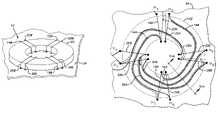
- FIG. 1is a perspective view of a transformer according to the invention.
- FIG. 2is a schematic diagram of the transformer of FIG. 1 .
- FIG. 3is a top x-ray view of the transformer of FIG. 1 .
- FIG. 3Ais a cross sectional view along the line 3 A.
- FIG. 4Ais a schematic diagram of another transformer.
- FIG. 4Bis a schematic diagram of the transformer of FIG. 4A modified for use in another transformer according to the invention.
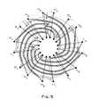
- FIG. 5is a top x-ray view of a transformer based on FIG. 4B according to the invention.
- FIG. 6is a schematic diagram and x-ray view of an additional transformer according to the invention.
- FIG. 7is a top x-ray view of still another transformer according to the invention.
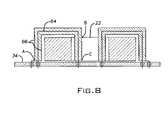
- FIG. 8is a cross sectional view showing the coaxial staples in a transformer according to the invention.
- FIG. 9is a top x-ray view of another additional transformer according to the invention.
- a transformer 10is shown schematically with a center-tapped primary winding 12 formed from the turns 14 , 16 , 18 , 20 .
- a magnetic core 22couples the winding 12 to the center-tapped secondary winding 24 formed from the turns 26 , 28 , 30 , 32 .
- the transformer 10may be advantageously implemented with an annular magnetic core 22 ; a printed circuit board 34 containing traces 14 A, 16 A, 18 A, 20 A forming first portions of the winding 12 , and traces 26 A, 28 A, 30 A, 32 A forming first portions of the winding 24 ; and staple-like conductors staples 14 B, 16 B, 18 B, 20 B forming second portions of the winding 12 and staples 26 B, 28 B, 30 B, 32 B forming second portions of the winding 24 .
- the core 22 ′is enlaced by the staples 14 A, 16 B, 18 B, 20 B, 26 B, 28 B, 30 B, 32 B when they are electrically and mechanically connected to the board 34 , for example, by soldering.
- the board 34may advantageously be of a multilayer type with for example, (see FIG. 3A ) a conductor (e.g., trace 26 A) shielded above and below by a wider conductor (e.g., traces 36 ) more fully explained below.
- the tracesmay be, for example, twice as wide as the sandwiched trace.
- the transformer 10takes this into account to minimize leakage inductance.
- the staple 14 B and the staple 16 B; the staple 26 B and the staple 28 B; the staple 18 B and the staple 20 B; and the staple 30 B and the staple 32 Bare located on opposite sides of the transformer 10 .
- the mutual inductances between turns that are carrying large currents at the same timeare reduced.
- Displacement current(for example, parasitic capacitive leakage) between the primary and secondary winding is another source of common mode current/noise.
- adjacent staplesare electrically moving in the same direction at the same time, thus minimizing displacement current.
- staple 14 Bis adjacent staple 26 B
- staple 16 Bis adjacent staple 28 B
- staple 18 Bis adjacent staple 30 B
- staple 20 Bis adjacent staple 32 B.
- the center taps of the transformerare static with respect to the transformer signals and therefore to not couple common mode current.
- the traces 36can act as either an electrostatic shield or a ground return, further improving the performance of the transformer 10 .
- a transformerhas a set of primary windings and two sets of secondary windings.
- a second set of primary windings in parallelcan be used as shown in the transformer 10 ′ of FIG. 4B .
- the staplesprefferably be symmetrically spaced about the core so that staples carrying large currents are symmetrically spaced away from each other and corresponding primary and secondary staples are located adjacent to each other.
- FIG. 5illustrates an embodiment of the transformer 10 ′ incorporating the above considerations, as well as electrostatic shielding of moving traces.
- the spacing for each turn of the winding halfis 180 degrees. Similarly, it is 120 degrees for three turns, 90 degrees for four turns, and so on.
- FIG. 6shows both a schematic and an embodiment of a transformer 10 ′′ having three turns in each winding half.
- transformer leakageis minimized by reducing the mutual inductance between turns within a winding and by increasing the mutual inductance between the primary and secondary turns. This suggests other configurations for improved performance transformers.
- FIG. 7is basically a bifiler winding of the primary and secondary windings of a transformer 50 .
- the printed circuit board, annular core, staple, shielded trace construction described aboveis employed, but the primary and secondary turns are arranged to be respectively adjacent.
- the voltage on the outer conductor 66is at the center-tap voltage.
- the point Cis moving about the center-tap voltage plus and minus the volts/turn of the transformer.
- coaxial staplesallows more freedom regarding which turns are next to each other. As the turns ratio of the transformer increases, limiting common mode signals becomes more of a problem. The exact symmetry of the placement of plain staples becomes more important. By using coaxial staples, the exact orientation of the staple becomes less important. The design can then tolerate more bent or misaligned staples.
- FIG. 9shows a 1:2 turns ratio transformer. It may be constructed using coaxial staples.
- An alternative to using coaxial staplesis to add additional turns to the primary winding so the turns ratio is one as in the previous designs, but without driving the additional turns.
Landscapes
- Engineering & Computer Science (AREA)
- Power Engineering (AREA)
- Regulation Of General Use Transformers (AREA)
Abstract
Description
The present invention relates to low noise transformers and, in particular, to transformers with low common mode noise.
In sensitive measurement equipment, the power transformer is often used to provide isolation from the measurement circuit. An unwanted common mode current from the transformer can easily corrupt or even obscure the electrical parameter to be measured.
Bulky transformers with expensive internal shields are commonly used to limit the common mode current to acceptable noise levels.
An inexpensive, compact, transformer with the desired characteristics would permit a less expensive and more compact measurement instrument to be produced.
A printed circuit board transformer has primary and secondary windings. The transformer includes a printed circuit board having a plurality of traces forming a plurality of first portions of the primary and secondary windings, an annular magnetic core adjacent to the printed circuit board, and a plurality of second portions of the primary and secondary windings. The second portions are formed from conductors enlacing the core.
Referring toFIG. 2 , atransformer 10 is shown schematically with a center-tappedprimary winding 12 formed from theturns magnetic core 22 couples the winding12 to the center-tappedsecondary winding 24 formed from theturns
Referring toFIGS. 1 and 3 , thetransformer 10 may be advantageously implemented with an annularmagnetic core 22; a printedcircuit board 34 containingtraces like conductors staples staples
Thecore 22′ is enlaced by thestaples board 34, for example, by soldering.
Theboard 34 may advantageously be of a multilayer type with for example, (seeFIG. 3A ) a conductor (e.g.,trace 26A) shielded above and below by a wider conductor (e.g., traces36) more fully explained below. The traces may be, for example, twice as wide as the sandwiched trace.
Many power applications draw large current from only one polarity of a power supply at a time. As a result, the large current flow in the secondary of a transformer flows in the winding in the winding above the center tap for one half of the transformer's input cycle and flows in the winding below the center tap for the other half of the input cycle. Similarly, it is common to drive a transformer's primary using a push-pull circuit. This results in current flowing only in the winding above the primary's center tap for the first half of the push-pull cycle and then flowing in the winding below the center tap during the other half of the push-pull cycle.
Thetransformer 10 takes this into account to minimize leakage inductance. Thestaple 14B and thestaple 16B; thestaple 26B and thestaple 28B; thestaple 18B and thestaple 20B; and thestaple 30B and thestaple 32B are located on opposite sides of thetransformer 10. By using this symmetrical arrangement of the staples, the mutual inductances between turns that are carrying large currents at the same time are reduced.
Displacement current (for example, parasitic capacitive leakage) between the primary and secondary winding is another source of common mode current/noise.
By locating primary staples adjacent to corresponding secondary staples, adjacent staples are electrically moving in the same direction at the same time, thus minimizing displacement current. For example,staple 14B isadjacent staple 26B,staple 16B isadjacent staple 28B,staple 18B isadjacent staple 30B, andstaple 20B isadjacent staple 32B.
Typically, the center taps of the transformer are static with respect to the transformer signals and therefore to not couple common mode current. This advantageously allows thewide traces 36 to be added to theboard 34 above and below electrically moving traces. All of thetraces 36 are connected to the either the primary or the secondary center tap. Thetraces 36 can act as either an electrostatic shield or a ground return, further improving the performance of thetransformer 10.
Referring toFIG. 4A , a transformer has a set of primary windings and two sets of secondary windings. In order to take advantage of the design techniques described above, a second set of primary windings in parallel can be used as shown in thetransformer 10′ ofFIG. 4B .
Then it is possible for the staples to be symmetrically spaced about the core so that staples carrying large currents are symmetrically spaced away from each other and corresponding primary and secondary staples are located adjacent to each other.
If the winding halves each have two windings, the spacing for each turn of the winding half is 180 degrees. Similarly, it is 120 degrees for three turns, 90 degrees for four turns, and so on.
In general, transformer leakage is minimized by reducing the mutual inductance between turns within a winding and by increasing the mutual inductance between the primary and secondary turns. This suggests other configurations for improved performance transformers.
Referring toFIG. 8 , further reduction in common mode current can be achieved by replacing the staples with coaxial conductors62. The inner conductor64 is connected according to the prior descriptions and theouter conductor 66 is connected at one end to the center-tap or other reference. If the outer connector is connected at the outside of thecore 22, theouter conductor 66 will be at the center-tap voltage except at the inside of thecore 22. All of the staples having shield that are moving the same reduces sensitivity to the symmetry of the staple placement.
From the points A to B, the voltage on theouter conductor 66 is at the center-tap voltage. The point C is moving about the center-tap voltage plus and minus the volts/turn of the transformer.
Using coaxial staples allows more freedom regarding which turns are next to each other. As the turns ratio of the transformer increases, limiting common mode signals becomes more of a problem. The exact symmetry of the placement of plain staples becomes more important. By using coaxial staples, the exact orientation of the staple becomes less important. The design can then tolerate more bent or misaligned staples.
It should be evident that this disclosure is by way of example and that various changes may be made by adding, modifying or eliminating details without departing from the fair scope of the teaching contained in this disclosure. The invention is therefore not limited to particular details of this disclosure except to the extent that the following claims are necessarily so limited.
Claims (6)
1. A printed circuit board transformer having primary and secondary windings, said transformer comprising:
a printed circuit board having a plurality of traces forming a plurality of first portions of said primary and secondary windings;
an annular magnetic core adjacent to said printed circuit board; and
a plurality of primary second portions of said primary windings and a plurality of secondary second portions of said secondary windings, said second portions being formed from conductors enlacing said core, wherein said primary second portions and said secondary second portions are each arranged in diametric pairs about said core.
2. A transformer according toclaim 1 , wherein said second portions are symmetrically spaced about said core.
3. A transformer according toclaim 1 , wherein each primary second portion is adjacent to a corresponding secondary second portion.
4. A transformer according toclaim 1 , wherein the trace of a first portion is electrically shielded by a trace in another layer of said printed circuit board.
5. A transformer according toclaim 1 , wherein the trace of a first portion is provided with a ground return by a trace in another layer of said printed circuit board.
6. A transformer according toclaim 1 , further comprising a coaxial conductor having an internal and an external conductor, said internal conductor corresponding to one of said second portions and said external conductor being connected at one end of said external conductor to a reference potential.
Priority Applications (1)
| Application Number | Priority Date | Filing Date | Title |
|---|---|---|---|
| US10/666,975US7009486B1 (en) | 2003-09-18 | 2003-09-18 | Low noise power transformer |
Applications Claiming Priority (1)
| Application Number | Priority Date | Filing Date | Title |
|---|---|---|---|
| US10/666,975US7009486B1 (en) | 2003-09-18 | 2003-09-18 | Low noise power transformer |
Publications (1)
| Publication Number | Publication Date |
|---|---|
| US7009486B1true US7009486B1 (en) | 2006-03-07 |
Family
ID=35966261
Family Applications (1)
| Application Number | Title | Priority Date | Filing Date |
|---|---|---|---|
| US10/666,975Expired - LifetimeUS7009486B1 (en) | 2003-09-18 | 2003-09-18 | Low noise power transformer |
Country Status (1)
| Country | Link |
|---|---|
| US (1) | US7009486B1 (en) |
Cited By (50)
| Publication number | Priority date | Publication date | Assignee | Title |
|---|---|---|---|---|
| US20060220774A1 (en)* | 2005-04-01 | 2006-10-05 | Veselin Skendzic | Precision printed circuit board based rogowski coil and method for manufacturing same |
| US20070075815A1 (en)* | 2005-10-05 | 2007-04-05 | Lotfi Ashraf W | Method of forming a magnetic device having a conductive clip |
| US20080007249A1 (en)* | 2006-07-06 | 2008-01-10 | Wilkerson Donovan E | Precision, temperature-compensated, shielded current measurement device |
| US20080150666A1 (en)* | 2005-02-23 | 2008-06-26 | Sriram Chandrasekaran | Power Converter Employing a Tapped Inductor and Integrated Magnetics and Method of Operating the Same |
| US20080204180A1 (en)* | 2007-02-26 | 2008-08-28 | Tony Aboumrad | High voltage transformer and a novel arrangement/method for hid automotive headlamps |
| WO2008131007A1 (en) | 2007-04-19 | 2008-10-30 | Harris Corporation | Embedded step-up toroidal transformer |
| US20080301929A1 (en)* | 2004-11-10 | 2008-12-11 | Lotfi Ashraf W | Method of Manufacturing a Power Module |
| US20080315852A1 (en)* | 2007-06-19 | 2008-12-25 | Chandrasekaran Jayaraman | System and Method for Estimating Input Power for a Power Processing Circuit |
| US20090097290A1 (en)* | 2007-03-14 | 2009-04-16 | Sriram Chandrasekaran | Isolated Power Converter |
| US20090160596A1 (en)* | 2007-12-19 | 2009-06-25 | Delta Electronics, Inc. | Magnetic device |
| US20100084750A1 (en)* | 2008-10-02 | 2010-04-08 | Lotfi Ashraf W | Module having a stacked passive element and method of forming the same |
| US20100091522A1 (en)* | 2002-04-18 | 2010-04-15 | Sriram Chandrasekaran | Extended E Matrix Integrated Magnetics (MIM) Core |
| US20100123486A1 (en)* | 2008-11-14 | 2010-05-20 | Berghegger Ralf Schroeder Genannt | Driver for a Synchronous Rectifier and Power Converter Employing the Same |
| US20100149838A1 (en)* | 2006-12-01 | 2010-06-17 | Artusi Daniel A | Power System with Power Converters Having an Adaptive Controller |
| US20100176905A1 (en)* | 2005-10-05 | 2010-07-15 | Lotfi Ashraf W | Magnetic Device Having a Conductive Clip |
| US20100188876A1 (en)* | 2009-01-19 | 2010-07-29 | Paul Garrity | Controller for a Power Converter |
| US20100212150A1 (en)* | 2008-10-02 | 2010-08-26 | Lotfi Ashraf W | Module Having a Stacked Magnetic Device and Semiconductor Device and Method of Forming the Same |
| US20100214746A1 (en)* | 2008-10-02 | 2010-08-26 | Lotfi Ashraf W | Module Having a Stacked Magnetic Device and Semiconductor Device and Method of Forming the Same |
| US20100254168A1 (en)* | 2009-03-31 | 2010-10-07 | Sriram Chandrasekaran | Magnetic Device Formed with U-Shaped Core Pieces and Power Converter Employing the Same |
| US20100321958A1 (en)* | 2009-06-17 | 2010-12-23 | Antony Brinlee | Power Converter Employing a Variable Switching Frequency and a Magnetic Device with a Non-Uniform Gap |
| US20110038179A1 (en)* | 2009-08-14 | 2011-02-17 | Xiaoyang Zhang | Power Converter Including a Charge Pump Employable in a Power Adapter |
| US20110134664A1 (en)* | 2009-12-03 | 2011-06-09 | Berghegger Ralf Schroeder Genannt | Startup Circuit and Power Converter Employing the Same |
| US20110149607A1 (en)* | 2009-12-18 | 2011-06-23 | Aaron Jungreis | Controller for a Power Converter |
| US20110182089A1 (en)* | 2010-01-22 | 2011-07-28 | Genannt Berghegger Ralf Schroeder | Controller for a Power Converter and Method of Operating the Same |
| US20110181383A1 (en)* | 2007-09-10 | 2011-07-28 | Lotfi Ashraf W | Micromagnetic Device and Method of Forming the Same |
| US20110205763A1 (en)* | 2006-12-01 | 2011-08-25 | Artusi Daniel A | Power Converter with an Adaptive Controller and Method of Operating the Same |
| US8520414B2 (en) | 2009-01-19 | 2013-08-27 | Power Systems Technologies, Ltd. | Controller for a power converter |
| US8643222B2 (en) | 2009-06-17 | 2014-02-04 | Power Systems Technologies Ltd | Power adapter employing a power reducer |
| US8701272B2 (en) | 2005-10-05 | 2014-04-22 | Enpirion, Inc. | Method of forming a power module with a magnetic device having a conductive clip |
| US8767418B2 (en) | 2010-03-17 | 2014-07-01 | Power Systems Technologies Ltd. | Control system for a power converter and method of operating the same |
| US8792257B2 (en) | 2011-03-25 | 2014-07-29 | Power Systems Technologies, Ltd. | Power converter with reduced power dissipation |
| US8792256B2 (en) | 2012-01-27 | 2014-07-29 | Power Systems Technologies Ltd. | Controller for a switch and method of operating the same |
| US8928337B2 (en) | 2012-01-27 | 2015-01-06 | Schweitzer Engineering Laboratories, Inc. | Device for measuring electrical current and method of manufacturing the same |
| US9077248B2 (en) | 2009-06-17 | 2015-07-07 | Power Systems Technologies Ltd | Start-up circuit for a power adapter |
| US9099232B2 (en) | 2012-07-16 | 2015-08-04 | Power Systems Technologies Ltd. | Magnetic device and power converter employing the same |
| US9106130B2 (en) | 2012-07-16 | 2015-08-11 | Power Systems Technologies, Inc. | Magnetic device and power converter employing the same |
| US9190898B2 (en) | 2012-07-06 | 2015-11-17 | Power Systems Technologies, Ltd | Controller for a power converter and method of operating the same |
| US9190204B1 (en) | 2013-05-12 | 2015-11-17 | Marion Harlan Cates, Jr. | Multilayer printed circuit board having circuit trace windings |
| US20150332836A1 (en)* | 2014-05-15 | 2015-11-19 | Analog Devices, Inc. | Magnetic devices and methods for manufacture using flex circuits |
| US9214264B2 (en) | 2012-07-16 | 2015-12-15 | Power Systems Technologies, Ltd. | Magnetic device and power converter employing the same |
| US9240712B2 (en) | 2012-12-13 | 2016-01-19 | Power Systems Technologies Ltd. | Controller including a common current-sense device for power switches of a power converter |
| US9246391B2 (en) | 2010-01-22 | 2016-01-26 | Power Systems Technologies Ltd. | Controller for providing a corrected signal to a sensed peak current through a circuit element of a power converter |
| US9300206B2 (en) | 2013-11-15 | 2016-03-29 | Power Systems Technologies Ltd. | Method for estimating power of a power converter |
| US9379629B2 (en) | 2012-07-16 | 2016-06-28 | Power Systems Technologies, Ltd. | Magnetic device and power converter employing the same |
| EP3067903A4 (en)* | 2013-11-08 | 2017-07-12 | Mitsubishi Electric Corporation | Electromagnetic induction apparatus |
| US20170372834A1 (en)* | 2015-04-24 | 2017-12-28 | Panasonic Intellectual Property Management Co., Ltd. | Transformer, and switching power supply and isolator including transformer |
| US10141107B2 (en) | 2013-10-10 | 2018-11-27 | Analog Devices, Inc. | Miniature planar transformer |
| US10573457B2 (en)* | 2014-10-17 | 2020-02-25 | Murata Manufacturing Co., Ltd. | Embedded magnetic component transformer device |
| US11617269B2 (en) | 2021-07-20 | 2023-03-28 | Schweitzer Engineering Laboratories, Inc. | Current measuring device for an electric power protection system |
| WO2024097226A1 (en)* | 2022-11-01 | 2024-05-10 | Tesla, Inc. | Electric motor with mitigation of electrically induced bearing damage (eibd) |
Citations (9)
| Publication number | Priority date | Publication date | Assignee | Title |
|---|---|---|---|---|
| US3453574A (en)* | 1968-03-22 | 1969-07-01 | Atomic Energy Commission | High-frequency,wide-band transformer |
| US3898595A (en)* | 1970-11-02 | 1975-08-05 | Cunningham Corp | Magnetic printed circuit |
| US4342976A (en)* | 1980-02-01 | 1982-08-03 | Hasler Ag | Pulse transformer |
| US4536733A (en)* | 1982-09-30 | 1985-08-20 | Sperry Corporation | High frequency inverter transformer for power supplies |
| US4755783A (en)* | 1986-11-18 | 1988-07-05 | Rogers Corporation | Inductive devices for printed wiring boards |
| US4777465A (en)* | 1986-04-28 | 1988-10-11 | Burr-Brown Corporation | Square toroid transformer for hybrid integrated circuit |
| US5543773A (en)* | 1990-09-07 | 1996-08-06 | Electrotech Instruments Limited | Transformers and coupled inductors with optimum interleaving of windings |
| US5966294A (en)* | 1996-12-20 | 1999-10-12 | Nec Corporation | Printed circuit board for prevention of unintentional electromagnetic interference |
| US6188305B1 (en)* | 1995-12-08 | 2001-02-13 | International Business Machines Corporation | Transformer formed in conjunction with printed circuit board |
- 2003
- 2003-09-18USUS10/666,975patent/US7009486B1/ennot_activeExpired - Lifetime
Patent Citations (9)
| Publication number | Priority date | Publication date | Assignee | Title |
|---|---|---|---|---|
| US3453574A (en)* | 1968-03-22 | 1969-07-01 | Atomic Energy Commission | High-frequency,wide-band transformer |
| US3898595A (en)* | 1970-11-02 | 1975-08-05 | Cunningham Corp | Magnetic printed circuit |
| US4342976A (en)* | 1980-02-01 | 1982-08-03 | Hasler Ag | Pulse transformer |
| US4536733A (en)* | 1982-09-30 | 1985-08-20 | Sperry Corporation | High frequency inverter transformer for power supplies |
| US4777465A (en)* | 1986-04-28 | 1988-10-11 | Burr-Brown Corporation | Square toroid transformer for hybrid integrated circuit |
| US4755783A (en)* | 1986-11-18 | 1988-07-05 | Rogers Corporation | Inductive devices for printed wiring boards |
| US5543773A (en)* | 1990-09-07 | 1996-08-06 | Electrotech Instruments Limited | Transformers and coupled inductors with optimum interleaving of windings |
| US6188305B1 (en)* | 1995-12-08 | 2001-02-13 | International Business Machines Corporation | Transformer formed in conjunction with printed circuit board |
| US5966294A (en)* | 1996-12-20 | 1999-10-12 | Nec Corporation | Printed circuit board for prevention of unintentional electromagnetic interference |
Cited By (82)
| Publication number | Priority date | Publication date | Assignee | Title |
|---|---|---|---|---|
| US20100091522A1 (en)* | 2002-04-18 | 2010-04-15 | Sriram Chandrasekaran | Extended E Matrix Integrated Magnetics (MIM) Core |
| US8134443B2 (en) | 2002-04-18 | 2012-03-13 | Flextronics International Usa, Inc. | Extended E matrix integrated magnetics (MIM) core |
| US20080301929A1 (en)* | 2004-11-10 | 2008-12-11 | Lotfi Ashraf W | Method of Manufacturing a Power Module |
| US8528190B2 (en) | 2004-11-10 | 2013-09-10 | Enpirion, Inc. | Method of manufacturing a power module |
| US7876191B2 (en) | 2005-02-23 | 2011-01-25 | Flextronics International Usa, Inc. | Power converter employing a tapped inductor and integrated magnetics and method of operating the same |
| US20080150666A1 (en)* | 2005-02-23 | 2008-06-26 | Sriram Chandrasekaran | Power Converter Employing a Tapped Inductor and Integrated Magnetics and Method of Operating the Same |
| WO2006108021A3 (en)* | 2005-04-01 | 2007-04-05 | Schweitzer Engineering Lab Inc | Precision printed circuit board based rogowski coil and method for manufacturing same |
| US7227442B2 (en)* | 2005-04-01 | 2007-06-05 | Schweitzer Engineering Laboratories, Inc. | Precision printed circuit board based rogowski coil and method for manufacturing same |
| US20060220774A1 (en)* | 2005-04-01 | 2006-10-05 | Veselin Skendzic | Precision printed circuit board based rogowski coil and method for manufacturing same |
| US8631560B2 (en) | 2005-10-05 | 2014-01-21 | Enpirion, Inc. | Method of forming a magnetic device having a conductive clip |
| US20070075815A1 (en)* | 2005-10-05 | 2007-04-05 | Lotfi Ashraf W | Method of forming a magnetic device having a conductive clip |
| US8384506B2 (en)* | 2005-10-05 | 2013-02-26 | Enpirion, Inc. | Magnetic device having a conductive clip |
| US20100176905A1 (en)* | 2005-10-05 | 2010-07-15 | Lotfi Ashraf W | Magnetic Device Having a Conductive Clip |
| US8701272B2 (en) | 2005-10-05 | 2014-04-22 | Enpirion, Inc. | Method of forming a power module with a magnetic device having a conductive clip |
| US7545138B2 (en) | 2006-07-06 | 2009-06-09 | Schweitzer Engineering Laboratories, Inc. | Precision, temperature-compensated, shielded current measurement device |
| US20080048646A1 (en)* | 2006-07-06 | 2008-02-28 | Schweitzer Engineering Laboratories, Inc. | Precision, temperature-compensated, shielded current measurement device |
| US20080007249A1 (en)* | 2006-07-06 | 2008-01-10 | Wilkerson Donovan E | Precision, temperature-compensated, shielded current measurement device |
| US20110205763A1 (en)* | 2006-12-01 | 2011-08-25 | Artusi Daniel A | Power Converter with an Adaptive Controller and Method of Operating the Same |
| US20100149838A1 (en)* | 2006-12-01 | 2010-06-17 | Artusi Daniel A | Power System with Power Converters Having an Adaptive Controller |
| US9197132B2 (en) | 2006-12-01 | 2015-11-24 | Flextronics International Usa, Inc. | Power converter with an adaptive controller and method of operating the same |
| US8477514B2 (en) | 2006-12-01 | 2013-07-02 | Flextronics International Usa, Inc. | Power system with power converters having an adaptive controller |
| US20080204180A1 (en)* | 2007-02-26 | 2008-08-28 | Tony Aboumrad | High voltage transformer and a novel arrangement/method for hid automotive headlamps |
| US8072308B2 (en)* | 2007-02-26 | 2011-12-06 | General Electric Company | High voltage transformer and a novel arrangement/method for hid automotive headlamps |
| US8502520B2 (en) | 2007-03-14 | 2013-08-06 | Flextronics International Usa, Inc | Isolated power converter |
| US20090097290A1 (en)* | 2007-03-14 | 2009-04-16 | Sriram Chandrasekaran | Isolated Power Converter |
| WO2008131007A1 (en) | 2007-04-19 | 2008-10-30 | Harris Corporation | Embedded step-up toroidal transformer |
| US7906941B2 (en) | 2007-06-19 | 2011-03-15 | Flextronics International Usa, Inc. | System and method for estimating input power for a power processing circuit |
| US20080315852A1 (en)* | 2007-06-19 | 2008-12-25 | Chandrasekaran Jayaraman | System and Method for Estimating Input Power for a Power Processing Circuit |
| US8618900B2 (en) | 2007-09-10 | 2013-12-31 | Enpirion, Inc. | Micromagnetic device and method of forming the same |
| US9299489B2 (en) | 2007-09-10 | 2016-03-29 | Enpirion, Inc. | Micromagnetic device and method of forming the same |
| US8339232B2 (en) | 2007-09-10 | 2012-12-25 | Enpirion, Inc. | Micromagnetic device and method of forming the same |
| US20110181383A1 (en)* | 2007-09-10 | 2011-07-28 | Lotfi Ashraf W | Micromagnetic Device and Method of Forming the Same |
| US7889047B2 (en)* | 2007-12-19 | 2011-02-15 | Delta Electronics Inc. | Magnetic device |
| US20090160596A1 (en)* | 2007-12-19 | 2009-06-25 | Delta Electronics, Inc. | Magnetic device |
| US20100214746A1 (en)* | 2008-10-02 | 2010-08-26 | Lotfi Ashraf W | Module Having a Stacked Magnetic Device and Semiconductor Device and Method of Forming the Same |
| US8266793B2 (en)* | 2008-10-02 | 2012-09-18 | Enpirion, Inc. | Module having a stacked magnetic device and semiconductor device and method of forming the same |
| US8339802B2 (en) | 2008-10-02 | 2012-12-25 | Enpirion, Inc. | Module having a stacked magnetic device and semiconductor device and method of forming the same |
| US20100084750A1 (en)* | 2008-10-02 | 2010-04-08 | Lotfi Ashraf W | Module having a stacked passive element and method of forming the same |
| US9054086B2 (en) | 2008-10-02 | 2015-06-09 | Enpirion, Inc. | Module having a stacked passive element and method of forming the same |
| US20100212150A1 (en)* | 2008-10-02 | 2010-08-26 | Lotfi Ashraf W | Module Having a Stacked Magnetic Device and Semiconductor Device and Method of Forming the Same |
| US20100123486A1 (en)* | 2008-11-14 | 2010-05-20 | Berghegger Ralf Schroeder Genannt | Driver for a Synchronous Rectifier and Power Converter Employing the Same |
| US8488355B2 (en) | 2008-11-14 | 2013-07-16 | Power Systems Technologies, Ltd. | Driver for a synchronous rectifier and power converter employing the same |
| US8520414B2 (en) | 2009-01-19 | 2013-08-27 | Power Systems Technologies, Ltd. | Controller for a power converter |
| US20100188876A1 (en)* | 2009-01-19 | 2010-07-29 | Paul Garrity | Controller for a Power Converter |
| US9088216B2 (en) | 2009-01-19 | 2015-07-21 | Power Systems Technologies, Ltd. | Controller for a synchronous rectifier switch |
| US20100254168A1 (en)* | 2009-03-31 | 2010-10-07 | Sriram Chandrasekaran | Magnetic Device Formed with U-Shaped Core Pieces and Power Converter Employing the Same |
| WO2010114914A1 (en)* | 2009-03-31 | 2010-10-07 | Flextronics International Usa, Inc. | Magnetic device formed with u-shaped core pieces and power converter employing the same |
| US9019061B2 (en) | 2009-03-31 | 2015-04-28 | Power Systems Technologies, Ltd. | Magnetic device formed with U-shaped core pieces and power converter employing the same |
| US8514593B2 (en) | 2009-06-17 | 2013-08-20 | Power Systems Technologies, Ltd. | Power converter employing a variable switching frequency and a magnetic device with a non-uniform gap |
| US8643222B2 (en) | 2009-06-17 | 2014-02-04 | Power Systems Technologies Ltd | Power adapter employing a power reducer |
| US20100321958A1 (en)* | 2009-06-17 | 2010-12-23 | Antony Brinlee | Power Converter Employing a Variable Switching Frequency and a Magnetic Device with a Non-Uniform Gap |
| US9077248B2 (en) | 2009-06-17 | 2015-07-07 | Power Systems Technologies Ltd | Start-up circuit for a power adapter |
| US8638578B2 (en) | 2009-08-14 | 2014-01-28 | Power System Technologies, Ltd. | Power converter including a charge pump employable in a power adapter |
| US20110038179A1 (en)* | 2009-08-14 | 2011-02-17 | Xiaoyang Zhang | Power Converter Including a Charge Pump Employable in a Power Adapter |
| US8976549B2 (en) | 2009-12-03 | 2015-03-10 | Power Systems Technologies, Ltd. | Startup circuit including first and second Schmitt triggers and power converter employing the same |
| US20110134664A1 (en)* | 2009-12-03 | 2011-06-09 | Berghegger Ralf Schroeder Genannt | Startup Circuit and Power Converter Employing the Same |
| US8520420B2 (en) | 2009-12-18 | 2013-08-27 | Power Systems Technologies, Ltd. | Controller for modifying dead time between switches in a power converter |
| US20110149607A1 (en)* | 2009-12-18 | 2011-06-23 | Aaron Jungreis | Controller for a Power Converter |
| US20110182089A1 (en)* | 2010-01-22 | 2011-07-28 | Genannt Berghegger Ralf Schroeder | Controller for a Power Converter and Method of Operating the Same |
| US8787043B2 (en) | 2010-01-22 | 2014-07-22 | Power Systems Technologies, Ltd. | Controller for a power converter and method of operating the same |
| US9246391B2 (en) | 2010-01-22 | 2016-01-26 | Power Systems Technologies Ltd. | Controller for providing a corrected signal to a sensed peak current through a circuit element of a power converter |
| US8767418B2 (en) | 2010-03-17 | 2014-07-01 | Power Systems Technologies Ltd. | Control system for a power converter and method of operating the same |
| US8792257B2 (en) | 2011-03-25 | 2014-07-29 | Power Systems Technologies, Ltd. | Power converter with reduced power dissipation |
| US8928337B2 (en) | 2012-01-27 | 2015-01-06 | Schweitzer Engineering Laboratories, Inc. | Device for measuring electrical current and method of manufacturing the same |
| US8792256B2 (en) | 2012-01-27 | 2014-07-29 | Power Systems Technologies Ltd. | Controller for a switch and method of operating the same |
| US9190898B2 (en) | 2012-07-06 | 2015-11-17 | Power Systems Technologies, Ltd | Controller for a power converter and method of operating the same |
| US9099232B2 (en) | 2012-07-16 | 2015-08-04 | Power Systems Technologies Ltd. | Magnetic device and power converter employing the same |
| US9379629B2 (en) | 2012-07-16 | 2016-06-28 | Power Systems Technologies, Ltd. | Magnetic device and power converter employing the same |
| US9106130B2 (en) | 2012-07-16 | 2015-08-11 | Power Systems Technologies, Inc. | Magnetic device and power converter employing the same |
| US9214264B2 (en) | 2012-07-16 | 2015-12-15 | Power Systems Technologies, Ltd. | Magnetic device and power converter employing the same |
| US9240712B2 (en) | 2012-12-13 | 2016-01-19 | Power Systems Technologies Ltd. | Controller including a common current-sense device for power switches of a power converter |
| US9190204B1 (en) | 2013-05-12 | 2015-11-17 | Marion Harlan Cates, Jr. | Multilayer printed circuit board having circuit trace windings |
| US10141107B2 (en) | 2013-10-10 | 2018-11-27 | Analog Devices, Inc. | Miniature planar transformer |
| EP3067903A4 (en)* | 2013-11-08 | 2017-07-12 | Mitsubishi Electric Corporation | Electromagnetic induction apparatus |
| US9300206B2 (en) | 2013-11-15 | 2016-03-29 | Power Systems Technologies Ltd. | Method for estimating power of a power converter |
| US20150332836A1 (en)* | 2014-05-15 | 2015-11-19 | Analog Devices, Inc. | Magnetic devices and methods for manufacture using flex circuits |
| US9959967B2 (en)* | 2014-05-15 | 2018-05-01 | Analog Devices, Inc. | Magnetic devices and methods for manufacture using flex circuits |
| US10573457B2 (en)* | 2014-10-17 | 2020-02-25 | Murata Manufacturing Co., Ltd. | Embedded magnetic component transformer device |
| US10276298B2 (en)* | 2015-04-24 | 2019-04-30 | Panasonic Intellectual Property Management Co., Ltd. | Transformer, and switching power supply and isolator including transformer |
| US20170372834A1 (en)* | 2015-04-24 | 2017-12-28 | Panasonic Intellectual Property Management Co., Ltd. | Transformer, and switching power supply and isolator including transformer |
| US11617269B2 (en) | 2021-07-20 | 2023-03-28 | Schweitzer Engineering Laboratories, Inc. | Current measuring device for an electric power protection system |
| WO2024097226A1 (en)* | 2022-11-01 | 2024-05-10 | Tesla, Inc. | Electric motor with mitigation of electrically induced bearing damage (eibd) |
Similar Documents
| Publication | Publication Date | Title |
|---|---|---|
| US7009486B1 (en) | Low noise power transformer | |
| US7369026B2 (en) | Method and apparatus for substantially reducing electrical displacement current flow between input and output circuits coupled to input and output windings of an energy transfer element | |
| US5521573A (en) | Printed coil | |
| US6717502B2 (en) | Integrated balun and transformer structures | |
| US7332993B1 (en) | Planar transformer having fractional windings | |
| US7414507B2 (en) | Planar transformer arrangement | |
| US7768369B2 (en) | Method and apparatus for substantially reducing electrical earth displacement current flow generated by wound components without requiring additional windings | |
| US9508484B2 (en) | Planar transmitter with a layered structure | |
| JP4125903B2 (en) | Method and apparatus for substantially reducing electrical ground displacement current generated by wound components | |
| JP2006286884A (en) | Common mode choke coil | |
| CN108933029A (en) | With the signal and power transmission integrated system being galvanically isolated | |
| US20230162905A1 (en) | Planar transformer including noise cancellation for auxiliary winding | |
| US20200052673A1 (en) | Common-mode choke coil | |
| US7616088B1 (en) | Low leakage inductance transformer | |
| CN101673611B (en) | Transformer and its applicable power conversion circuit for reducing the influence of electromagnetic interference | |
| JP2010525600A (en) | Planar transducer with substrate | |
| KR102366027B1 (en) | Transformer arrangement, circuit arrangement, and method of operating the transformer arrangement | |
| CN113380517B (en) | Magnetic leakage transformer | |
| US11694832B2 (en) | High voltage high frequency transformer | |
| US20200251270A1 (en) | High voltage high frequency transformer |
Legal Events
| Date | Code | Title | Description |
|---|---|---|---|
| AS | Assignment | Owner name:KEITHLEY INSTRUMENTS, INC., OHIO Free format text:ASSIGNMENT OF ASSIGNORS INTEREST;ASSIGNORS:GOEKE, WAYNE;SYPEN, ART;REEL/FRAME:014623/0766 Effective date:20031008 | |
| FEPP | Fee payment procedure | Free format text:PAYOR NUMBER ASSIGNED (ORIGINAL EVENT CODE: ASPN); ENTITY STATUS OF PATENT OWNER: LARGE ENTITY | |
| STCF | Information on status: patent grant | Free format text:PATENTED CASE | |
| CC | Certificate of correction | ||
| FPAY | Fee payment | Year of fee payment:4 | |
| FEPP | Fee payment procedure | Free format text:PAYER NUMBER DE-ASSIGNED (ORIGINAL EVENT CODE: RMPN); ENTITY STATUS OF PATENT OWNER: LARGE ENTITY Free format text:PAYOR NUMBER ASSIGNED (ORIGINAL EVENT CODE: ASPN); ENTITY STATUS OF PATENT OWNER: LARGE ENTITY | |
| FPAY | Fee payment | Year of fee payment:8 | |
| MAFP | Maintenance fee payment | Free format text:PAYMENT OF MAINTENANCE FEE, 12TH YEAR, LARGE ENTITY (ORIGINAL EVENT CODE: M1553) Year of fee payment:12 |