US7008428B2 - Bone fixation system - Google Patents
Bone fixation systemDownload PDFInfo
- Publication number
- US7008428B2 US7008428B2US10/440,016US44001603AUS7008428B2US 7008428 B2US7008428 B2US 7008428B2US 44001603 AUS44001603 AUS 44001603AUS 7008428 B2US7008428 B2US 7008428B2
- Authority
- US
- United States
- Prior art keywords
- bone
- pin
- proximal
- anchor
- distal
- Prior art date
- Legal status (The legal status is an assumption and is not a legal conclusion. Google has not performed a legal analysis and makes no representation as to the accuracy of the status listed.)
- Expired - Fee Related
Links
- 210000000988bone and boneAnatomy0.000titleclaimsabstractdescription151
- 238000000034methodMethods0.000claimsdescription26
- 210000002435tendonAnatomy0.000abstractdescription9
- 239000012634fragmentSubstances0.000abstractdescription8
- 229910052751metalInorganic materials0.000abstractdescription7
- 239000002184metalSubstances0.000abstractdescription7
- RTAQQCXQSZGOHL-UHFFFAOYSA-NTitaniumChemical compound[Ti]RTAQQCXQSZGOHL-UHFFFAOYSA-N0.000abstractdescription6
- 210000004872soft tissueAnatomy0.000abstractdescription6
- 239000010936titaniumSubstances0.000abstractdescription6
- 229910052719titaniumInorganic materials0.000abstractdescription6
- 238000010276constructionMethods0.000abstractdescription4
- 230000014759maintenance of locationEffects0.000description63
- 239000000463materialSubstances0.000description27
- 206010017076FractureDiseases0.000description22
- 208000010392Bone FracturesDiseases0.000description16
- 230000004323axial lengthEffects0.000description11
- 230000033001locomotionEffects0.000description11
- 230000035876healingEffects0.000description9
- 238000009434installationMethods0.000description9
- 229920000642polymerPolymers0.000description9
- 210000001519tissueAnatomy0.000description9
- 230000006835compressionEffects0.000description7
- 238000007906compressionMethods0.000description7
- 239000007943implantSubstances0.000description7
- 238000002513implantationMethods0.000description7
- 206010052428WoundDiseases0.000description5
- 208000027418Wounds and injuryDiseases0.000description5
- 230000001054cortical effectEffects0.000description5
- 238000013461designMethods0.000description5
- 210000002683footAnatomy0.000description5
- 238000004519manufacturing processMethods0.000description5
- 230000001954sterilising effectEffects0.000description5
- 238000004659sterilization and disinfectionMethods0.000description5
- 208000037873arthrodesisDiseases0.000description4
- 230000000295complement effectEffects0.000description4
- 239000004035construction materialSubstances0.000description4
- 230000008878couplingEffects0.000description4
- 238000010168coupling processMethods0.000description4
- 238000005859coupling reactionMethods0.000description4
- 239000000835fiberSubstances0.000description4
- 230000005012migrationEffects0.000description4
- 238000013508migrationMethods0.000description4
- 230000037361pathwayEffects0.000description4
- -1polyethylenePolymers0.000description4
- 230000006641stabilisationEffects0.000description4
- 238000011105stabilizationMethods0.000description4
- 230000009102absorptionEffects0.000description3
- 238000010521absorption reactionMethods0.000description3
- 238000005553drillingMethods0.000description3
- 208000014674injuryDiseases0.000description3
- 210000003041ligamentAnatomy0.000description3
- 210000001872metatarsal boneAnatomy0.000description3
- 239000000203mixtureSubstances0.000description3
- 238000000465mouldingMethods0.000description3
- 230000000704physical effectEffects0.000description3
- 239000000126substanceSubstances0.000description3
- 238000001356surgical procedureMethods0.000description3
- 206010031252OsteomyelitisDiseases0.000description2
- 239000003242anti bacterial agentSubstances0.000description2
- 238000005452bendingMethods0.000description2
- 230000000975bioactive effectEffects0.000description2
- 230000003115biocidal effectEffects0.000description2
- 230000008468bone growthEffects0.000description2
- 239000002775capsuleSubstances0.000description2
- 239000000919ceramicSubstances0.000description2
- 238000007796conventional methodMethods0.000description2
- 230000006378damageEffects0.000description2
- 230000002708enhancing effectEffects0.000description2
- 239000000155meltSubstances0.000description2
- 238000012986modificationMethods0.000description2
- 230000004048modificationEffects0.000description2
- 229920001432poly(L-lactide)Polymers0.000description2
- 229920000117poly(dioxanone)Polymers0.000description2
- 230000008569processEffects0.000description2
- 238000011321prophylaxisMethods0.000description2
- 230000009103reabsorptionEffects0.000description2
- 239000007787solidSubstances0.000description2
- 239000010935stainless steelSubstances0.000description2
- 229910001220stainless steelInorganic materials0.000description2
- 230000008733traumaEffects0.000description2
- JJTUDXZGHPGLLC-IMJSIDKUSA-N4511-42-6Chemical compoundC[C@@H]1OC(=O)[C@H](C)OC1=OJJTUDXZGHPGLLC-IMJSIDKUSA-N0.000description1
- 206010053555Arthritis bacterialDiseases0.000description1
- GUTLYIVDDKVIGB-OUBTZVSYSA-NCobalt-60Chemical compound[60Co]GUTLYIVDDKVIGB-OUBTZVSYSA-N0.000description1
- IAYPIBMASNFSPL-UHFFFAOYSA-NEthylene oxideChemical compoundC1CO1IAYPIBMASNFSPL-UHFFFAOYSA-N0.000description1
- AEMRFAOFKBGASW-UHFFFAOYSA-NGlycolic acidPolymersOCC(O)=OAEMRFAOFKBGASW-UHFFFAOYSA-N0.000description1
- 208000004575Infectious ArthritisDiseases0.000description1
- 229920000339MarlexPolymers0.000description1
- 239000004677NylonSubstances0.000description1
- 229920001244Poly(D,L-lactide)Polymers0.000description1
- 239000004698PolyethyleneSubstances0.000description1
- 229920000954PolyglycolidePolymers0.000description1
- 239000004743PolypropyleneSubstances0.000description1
- 206010061363Skeletal injuryDiseases0.000description1
- 229910001069Ti alloyInorganic materials0.000description1
- 206010000269abscessDiseases0.000description1
- 239000002253acidSubstances0.000description1
- 239000000853adhesiveSubstances0.000description1
- 230000001070adhesive effectEffects0.000description1
- 230000002491angiogenic effectEffects0.000description1
- 210000003423ankleAnatomy0.000description1
- 230000003466anti-cipated effectEffects0.000description1
- 229940088710antibiotic agentDrugs0.000description1
- 230000009286beneficial effectEffects0.000description1
- 239000005313bioactive glassSubstances0.000description1
- 229920002988biodegradable polymerPolymers0.000description1
- 239000004621biodegradable polymerSubstances0.000description1
- 239000012620biological materialSubstances0.000description1
- 210000001124body fluidAnatomy0.000description1
- 239000010839body fluidSubstances0.000description1
- 239000006227byproductSubstances0.000description1
- 238000010349cathodic reactionMethods0.000description1
- 239000003795chemical substances by applicationSubstances0.000description1
- 230000000973chemotherapeutic effectEffects0.000description1
- 239000011247coating layerSubstances0.000description1
- 238000000748compression mouldingMethods0.000description1
- 230000008602contractionEffects0.000description1
- 238000001816coolingMethods0.000description1
- 229920001577copolymerPolymers0.000description1
- 238000005520cutting processMethods0.000description1
- 239000003814drugSubstances0.000description1
- 229940079593drugDrugs0.000description1
- 230000000694effectsEffects0.000description1
- 230000005489elastic deformationEffects0.000description1
- 238000010894electron beam technologyMethods0.000description1
- 238000001125extrusionMethods0.000description1
- 210000000109fascia lataAnatomy0.000description1
- 239000003527fibrinolytic agentSubstances0.000description1
- 210000002082fibulaAnatomy0.000description1
- 239000006260foamSubstances0.000description1
- 239000006261foam materialSubstances0.000description1
- 239000003102growth factorSubstances0.000description1
- 239000000122growth hormoneSubstances0.000description1
- 239000013003healing agentSubstances0.000description1
- 229910052588hydroxylapatiteInorganic materials0.000description1
- 238000001727in vivoMethods0.000description1
- 238000011065in-situ storageMethods0.000description1
- 208000015181infectious diseaseDiseases0.000description1
- 238000001746injection mouldingMethods0.000description1
- 230000007794irritationEffects0.000description1
- 210000003127kneeAnatomy0.000description1
- 210000002414legAnatomy0.000description1
- 238000003754machiningMethods0.000description1
- 150000002739metalsChemical class0.000description1
- 210000000450navicular boneAnatomy0.000description1
- 229910001000nickel titaniumInorganic materials0.000description1
- HLXZNVUGXRDIFK-UHFFFAOYSA-Nnickel titaniumChemical compound[Ti].[Ti].[Ti].[Ti].[Ti].[Ti].[Ti].[Ti].[Ti].[Ti].[Ti].[Ni].[Ni].[Ni].[Ni].[Ni].[Ni].[Ni].[Ni].[Ni].[Ni].[Ni].[Ni].[Ni].[Ni]HLXZNVUGXRDIFK-UHFFFAOYSA-N0.000description1
- 231100000252nontoxicToxicity0.000description1
- 230000003000nontoxic effectEffects0.000description1
- 229920001778nylonPolymers0.000description1
- 238000005457optimizationMethods0.000description1
- XYJRXVWERLGGKC-UHFFFAOYSA-Dpentacalcium;hydroxide;triphosphateChemical compound[OH-].[Ca+2].[Ca+2].[Ca+2].[Ca+2].[Ca+2].[O-]P([O-])([O-])=O.[O-]P([O-])([O-])=O.[O-]P([O-])([O-])=OXYJRXVWERLGGKC-UHFFFAOYSA-D0.000description1
- 230000002093peripheral effectEffects0.000description1
- 229920006209poly(L-lactide-co-D,L-lactide)Polymers0.000description1
- 229920002463poly(p-dioxanone) polymerPolymers0.000description1
- 229920001610polycaprolactonePolymers0.000description1
- 239000004632polycaprolactoneSubstances0.000description1
- 229920000515polycarbonatePolymers0.000description1
- 239000004417polycarbonateSubstances0.000description1
- 239000000622polydioxanoneSubstances0.000description1
- 229920006149polyester-amide block copolymerPolymers0.000description1
- 229920000573polyethylenePolymers0.000description1
- 229920002959polymer blendPolymers0.000description1
- 229920001155polypropylenePolymers0.000description1
- 230000005855radiationEffects0.000description1
- 230000003014reinforcing effectEffects0.000description1
- 239000012783reinforcing fiberSubstances0.000description1
- 230000004044responseEffects0.000description1
- 230000000717retained effectEffects0.000description1
- 239000011265semifinished productSubstances0.000description1
- 201000001223septic arthritisDiseases0.000description1
- 210000002832shoulderAnatomy0.000description1
- 238000004513sizingMethods0.000description1
- 239000011343solid materialSubstances0.000description1
- 239000002904solventSubstances0.000description1
- 230000000087stabilizing effectEffects0.000description1
- 239000000725suspensionSubstances0.000description1
- 229920002994synthetic fiberPolymers0.000description1
- 210000002303tibiaAnatomy0.000description1
- 238000011282treatmentMethods0.000description1
- 238000009966trimmingMethods0.000description1
Images


Classifications
- A—HUMAN NECESSITIES
- A61—MEDICAL OR VETERINARY SCIENCE; HYGIENE
- A61B—DIAGNOSIS; SURGERY; IDENTIFICATION
- A61B17/00—Surgical instruments, devices or methods
- A61B17/56—Surgical instruments or methods for treatment of bones or joints; Devices specially adapted therefor
- A61B17/58—Surgical instruments or methods for treatment of bones or joints; Devices specially adapted therefor for osteosynthesis, e.g. bone plates, screws or setting implements
- A61B17/68—Internal fixation devices, including fasteners and spinal fixators, even if a part thereof projects from the skin
- A61B17/683—Internal fixation devices, including fasteners and spinal fixators, even if a part thereof projects from the skin comprising bone transfixation elements, e.g. bolt with a distal cooperating element such as a nut
- A—HUMAN NECESSITIES
- A61—MEDICAL OR VETERINARY SCIENCE; HYGIENE
- A61B—DIAGNOSIS; SURGERY; IDENTIFICATION
- A61B17/00—Surgical instruments, devices or methods
- A61B17/56—Surgical instruments or methods for treatment of bones or joints; Devices specially adapted therefor
- A61B17/58—Surgical instruments or methods for treatment of bones or joints; Devices specially adapted therefor for osteosynthesis, e.g. bone plates, screws or setting implements
- A61B17/68—Internal fixation devices, including fasteners and spinal fixators, even if a part thereof projects from the skin
- A61B17/72—Intramedullary devices, e.g. pins or nails
- A61B17/7216—Intramedullary devices, e.g. pins or nails for bone lengthening or compression
- A61B17/7225—Intramedullary devices, e.g. pins or nails for bone lengthening or compression for bone compression
- A—HUMAN NECESSITIES
- A61—MEDICAL OR VETERINARY SCIENCE; HYGIENE
- A61B—DIAGNOSIS; SURGERY; IDENTIFICATION
- A61B17/00—Surgical instruments, devices or methods
- A61B17/56—Surgical instruments or methods for treatment of bones or joints; Devices specially adapted therefor
- A61B17/58—Surgical instruments or methods for treatment of bones or joints; Devices specially adapted therefor for osteosynthesis, e.g. bone plates, screws or setting implements
- A61B17/68—Internal fixation devices, including fasteners and spinal fixators, even if a part thereof projects from the skin
- A61B17/72—Intramedullary devices, e.g. pins or nails
- A61B17/7233—Intramedullary devices, e.g. pins or nails with special means of locking the nail to the bone
- A61B17/7258—Intramedullary devices, e.g. pins or nails with special means of locking the nail to the bone with laterally expanding parts, e.g. for gripping the bone
- A61B17/7266—Intramedullary devices, e.g. pins or nails with special means of locking the nail to the bone with laterally expanding parts, e.g. for gripping the bone with fingers moving radially outwardly
- A—HUMAN NECESSITIES
- A61—MEDICAL OR VETERINARY SCIENCE; HYGIENE
- A61B—DIAGNOSIS; SURGERY; IDENTIFICATION
- A61B17/00—Surgical instruments, devices or methods
- A61B17/56—Surgical instruments or methods for treatment of bones or joints; Devices specially adapted therefor
- A61B17/58—Surgical instruments or methods for treatment of bones or joints; Devices specially adapted therefor for osteosynthesis, e.g. bone plates, screws or setting implements
- A61B17/68—Internal fixation devices, including fasteners and spinal fixators, even if a part thereof projects from the skin
- A61B17/72—Intramedullary devices, e.g. pins or nails
- A61B17/7291—Intramedullary devices, e.g. pins or nails for small bones, e.g. in the foot, ankle, hand or wrist
- A—HUMAN NECESSITIES
- A61—MEDICAL OR VETERINARY SCIENCE; HYGIENE
- A61B—DIAGNOSIS; SURGERY; IDENTIFICATION
- A61B17/00—Surgical instruments, devices or methods
- A61B17/56—Surgical instruments or methods for treatment of bones or joints; Devices specially adapted therefor
- A61B17/58—Surgical instruments or methods for treatment of bones or joints; Devices specially adapted therefor for osteosynthesis, e.g. bone plates, screws or setting implements
- A61B17/68—Internal fixation devices, including fasteners and spinal fixators, even if a part thereof projects from the skin
- A61B17/84—Fasteners therefor or fasteners being internal fixation devices
- A61B17/86—Pins or screws or threaded wires; nuts therefor
- A61B17/8685—Pins or screws or threaded wires; nuts therefor comprising multiple separate parts
- A—HUMAN NECESSITIES
- A61—MEDICAL OR VETERINARY SCIENCE; HYGIENE
- A61B—DIAGNOSIS; SURGERY; IDENTIFICATION
- A61B17/00—Surgical instruments, devices or methods
- A61B2017/00004—(bio)absorbable, (bio)resorbable or resorptive
- A—HUMAN NECESSITIES
- A61—MEDICAL OR VETERINARY SCIENCE; HYGIENE
- A61B—DIAGNOSIS; SURGERY; IDENTIFICATION
- A61B17/00—Surgical instruments, devices or methods
- A61B17/04—Surgical instruments, devices or methods for suturing wounds; Holders or packages for needles or suture materials
- A61B17/0401—Suture anchors, buttons or pledgets, i.e. means for attaching sutures to bone, cartilage or soft tissue; Instruments for applying or removing suture anchors
- A61B2017/0412—Suture anchors, buttons or pledgets, i.e. means for attaching sutures to bone, cartilage or soft tissue; Instruments for applying or removing suture anchors having anchoring barbs or pins extending outwardly from suture anchor body
- A—HUMAN NECESSITIES
- A61—MEDICAL OR VETERINARY SCIENCE; HYGIENE
- A61B—DIAGNOSIS; SURGERY; IDENTIFICATION
- A61B17/00—Surgical instruments, devices or methods
- A61B17/04—Surgical instruments, devices or methods for suturing wounds; Holders or packages for needles or suture materials
- A61B17/0401—Suture anchors, buttons or pledgets, i.e. means for attaching sutures to bone, cartilage or soft tissue; Instruments for applying or removing suture anchors
- A61B2017/042—Suture anchors, buttons or pledgets, i.e. means for attaching sutures to bone, cartilage or soft tissue; Instruments for applying or removing suture anchors plastically deformed during insertion
- A61B2017/0422—Suture anchors, buttons or pledgets, i.e. means for attaching sutures to bone, cartilage or soft tissue; Instruments for applying or removing suture anchors plastically deformed during insertion by insertion of a separate member into the body of the anchor
- A61B2017/0424—Suture anchors, buttons or pledgets, i.e. means for attaching sutures to bone, cartilage or soft tissue; Instruments for applying or removing suture anchors plastically deformed during insertion by insertion of a separate member into the body of the anchor the separate member staying in the anchor after placement
- A—HUMAN NECESSITIES
- A61—MEDICAL OR VETERINARY SCIENCE; HYGIENE
- A61B—DIAGNOSIS; SURGERY; IDENTIFICATION
- A61B17/00—Surgical instruments, devices or methods
- A61B17/04—Surgical instruments, devices or methods for suturing wounds; Holders or packages for needles or suture materials
- A61B17/0401—Suture anchors, buttons or pledgets, i.e. means for attaching sutures to bone, cartilage or soft tissue; Instruments for applying or removing suture anchors
- A61B2017/0427—Suture anchors, buttons or pledgets, i.e. means for attaching sutures to bone, cartilage or soft tissue; Instruments for applying or removing suture anchors having anchoring barbs or pins extending outwardly from the anchor body
- A61B2017/0437—Suture anchors, buttons or pledgets, i.e. means for attaching sutures to bone, cartilage or soft tissue; Instruments for applying or removing suture anchors having anchoring barbs or pins extending outwardly from the anchor body the barbs being resilient or spring-like
- A—HUMAN NECESSITIES
- A61—MEDICAL OR VETERINARY SCIENCE; HYGIENE
- A61B—DIAGNOSIS; SURGERY; IDENTIFICATION
- A61B17/00—Surgical instruments, devices or methods
- A61B17/04—Surgical instruments, devices or methods for suturing wounds; Holders or packages for needles or suture materials
- A61B17/0401—Suture anchors, buttons or pledgets, i.e. means for attaching sutures to bone, cartilage or soft tissue; Instruments for applying or removing suture anchors
- A61B2017/0438—Suture anchors, buttons or pledgets, i.e. means for attaching sutures to bone, cartilage or soft tissue; Instruments for applying or removing suture anchors slotted, i.e. having a longitudinal slot for enhancing their elasticity
- A—HUMAN NECESSITIES
- A61—MEDICAL OR VETERINARY SCIENCE; HYGIENE
- A61B—DIAGNOSIS; SURGERY; IDENTIFICATION
- A61B17/00—Surgical instruments, devices or methods
- A61B17/04—Surgical instruments, devices or methods for suturing wounds; Holders or packages for needles or suture materials
- A61B17/0401—Suture anchors, buttons or pledgets, i.e. means for attaching sutures to bone, cartilage or soft tissue; Instruments for applying or removing suture anchors
- A61B2017/044—Suture anchors, buttons or pledgets, i.e. means for attaching sutures to bone, cartilage or soft tissue; Instruments for applying or removing suture anchors with a threaded shaft, e.g. screws
- A—HUMAN NECESSITIES
- A61—MEDICAL OR VETERINARY SCIENCE; HYGIENE
- A61F—FILTERS IMPLANTABLE INTO BLOOD VESSELS; PROSTHESES; DEVICES PROVIDING PATENCY TO, OR PREVENTING COLLAPSING OF, TUBULAR STRUCTURES OF THE BODY, e.g. STENTS; ORTHOPAEDIC, NURSING OR CONTRACEPTIVE DEVICES; FOMENTATION; TREATMENT OR PROTECTION OF EYES OR EARS; BANDAGES, DRESSINGS OR ABSORBENT PADS; FIRST-AID KITS
- A61F2/00—Filters implantable into blood vessels; Prostheses, i.e. artificial substitutes or replacements for parts of the body; Appliances for connecting them with the body; Devices providing patency to, or preventing collapsing of, tubular structures of the body, e.g. stents
- A61F2/02—Prostheses implantable into the body
- A61F2/08—Muscles; Tendons; Ligaments
- A61F2/0811—Fixation devices for tendons or ligaments
- Y—GENERAL TAGGING OF NEW TECHNOLOGICAL DEVELOPMENTS; GENERAL TAGGING OF CROSS-SECTIONAL TECHNOLOGIES SPANNING OVER SEVERAL SECTIONS OF THE IPC; TECHNICAL SUBJECTS COVERED BY FORMER USPC CROSS-REFERENCE ART COLLECTIONS [XRACs] AND DIGESTS
- Y10—TECHNICAL SUBJECTS COVERED BY FORMER USPC
- Y10S—TECHNICAL SUBJECTS COVERED BY FORMER USPC CROSS-REFERENCE ART COLLECTIONS [XRACs] AND DIGESTS
- Y10S606/00—Surgery
- Y10S606/907—Composed of particular material or coated
Definitions
- the present inventionrelates to bone fixation systems and, more particularly, deployment devices and absorbable or nonabsorbable bone fixation pins of the type for fixing soft tissue or tendons to bone or for securing two or more adjacent bone fragments or bones together.
- the surgical procedure of attaching two or more parts of a bone with a pin-like devicerequires an incision into the tissue surrounding the bone and the drilling of a hole through the bone parts to be joined. Due to the significant variation in bone size, configuration, and load requirements, a wide variety of bone fixation devices have been developed in the prior art. In general, the current standard of care relies upon a variety of metal wires, screws, and clamps to stabilize the bone fragments during the healing process. Following a sufficient bone healing period of time, the percutaneous access site or other site may require re-opening to permit removal of the bone fixation device.
- K-wiresKirschner wires
- intramedullary pinswiring, plates, screws, and combinations of the foregoing.
- the particular device or combination of devicesis selected to achieve the best anatomic and functional condition of the traumatized bone with the simplest operative procedure and with a minimal use of foreign-implanted stabilizing material.
- alternate bone fixation devicesare also known in the art, such as, for example, those disclosed in U.S. Pat. No. 4,688,561 to Reese, U.S. Pat. No. 4,790,304 to Rosenberg, and U.S. Pat. No. 5,370,646 to Reese, et al.
- K-wire fixationis attended by certain known risks. For example, a second surgical procedure is required to remove the device after healing is complete. Removal is recommended, because otherwise the bone adjacent to an implant becomes vulnerable to stress shielding as a result of the differences in the modulus of elasticity and density between metal and the bone.
- an implanted K-wiremay provide a site for a variety of complications ranging from pin-tract infections to abscesses, resistant osteomyelitis, septic arthritis, and infected nonunion.
- K-wiresAnother potential complication involving the use of K-wires is in vivo migration. Axial migration of K-wires has been reported to range from 0 mm to 20 mm, which can both increase the difficulty of pin removal as well as inflict trauma to adjacent tissue.
- K-wiresproject through the skin.
- percutaneously extending K-wirescan be disrupted or cause damage to adjacent structures such as tendons if the K-wire comes into contact with external objects.
- a fixation pinfor fixing bone to bone or other tissue to bone.
- the fixation pincomprises a body, having a proximal end and a distal end.
- a distal anchoris on the body.
- the distal anchorcomprises at least a first retention surface on a first axially extending lever arm and a second retention surface on a second axially extending lever arm.
- the first and second retention surfacesare laterally moveable between a first, implantation crossing profile and a second, larger, deployed crossing profile.
- the first and second retention structuresare preferably biased in the direction of the second crossing profile.
- at least three retention surfaces and at least three lever armsare provided.
- the fixation pinmay be integrally formed from a single piece of metal which may comprise titanium.
- the fixation pinmay further comprise a retention structure on the body, for retaining a proximal anchor.
- the retention structuremay comprise a deviation in the surface of the body, such as an annular ridge, helical thread, or other recess or projection.
- a proximal anchoris moveably carried by the body.
- the fixation pinmay additionally comprise at least one breakpoint on the body, for allowing a proximal projection of the body to be snapped off, following tensioning of the proximal anchor.
- a fixation pinfor bone to bone or other tissue to bone fixation.
- the fixation pincomprises a tubular body, having a proximal end and a distal end. At least two slots are provided in the tubular body, extending proximally from the distal end to define at least a first and a second axially extending lever arms. A proximally facing retention surface is carried by each lever arm.
- a retention structureis also provided on the body, for removably carrying a proximal anchor. The first and second retention surfaces are laterally moveable between an implantation crossing profile and a deployed crossing profile.
- the retention structuremay comprise a thread on the body, proximal to at least a portion of the lever arms.
- a proximal anchoris moveably carried by the thread.
- a method of fixing a first material to bonecomprises the steps of providing a pin having a distal anchor and at least one proximal breakpoint.
- the distal anchoris advanced through the first material and into the bone.
- a proximal anchoris advanced distally along the pin to secure the first material to the bone. Lateral pressure is applied to a proximal portion of the pin, to break the pin at the breakpoint.
- the first materialcomprises bone.
- the first materialcomprises soft tissue, tendon, graft or other synthetic or natural biological material.
- the advancing the distal anchor stepcomprises advancing the distal anchor all the way through the bone.
- the advancing a proximal anchor stepmay comprise rotating the proximal anchor with respect to the pin.
- the methodmay further comprise the step of removing the proximal anchor by rotating the proximal anchor with respect to the pin.
- a core drillmay thereafter be advanced over the pin, and the pin removed from the bone.
- a fixation pinfor fixing a first material to bone.
- the pincomprises an elongate tubular body, having a proximal end and a distal end. A plurality of deflectable barbs are carried by the distal end.
- a threadis provided on the tubular body, in-between the proximal end and the distal end, and a break point is provided on the tubular body, proximal to at least a portion of the thread.
- the pinmay further comprise a proximal anchor, removably retained on the tubular body by the thread.
- a rotational couplingis provided on the pin, for coupling to a tool.
- a second rotational couplingis provided on the anchor, to permit rotation of the anchor while resisting rotation of the pin.
- Each of the barbsmay be attached to the tubular body by an axially extending lever arm.
- FIG. 1is a cross-sectional schematic view of a bone fixation device of the present invention positioned within a fractured bone.
- FIG. 2is a longitudinal cross-sectional view through the pin body of the present invention.
- FIG. 3is a distal end elevational view of the pin body of FIG. 2 .
- FIG. 4is a longitudinal cross-sectional view of the proximal anchor of the bone fixation device.
- FIG. 5is a proximal end elevational view of the proximal anchor of the bone fixation device.
- FIG. 6is a side elevational view of an alternate embodiment of the bone fixation device of the present invention.
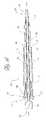
- FIG. 7is a side elevational view of an alternate embodiment of the pin body in accordance with the present invention.
- FIG. 8is a longitudinal cross-sectional view through the pin body of FIG. 7 .
- FIG. 9is a distal end elevational view of the pin body of FIG. 7 .
- FIG. 10is an enlarged detail view of the distal end of the device shown in FIG. 8 .
- FIG. 11is a cross-sectional view through a proximal anchor for use with the pin body of FIG. 7 .
- FIG. 12is a proximal end elevational view of the proximal anchor end of FIG. 11 .
- FIG. 13is a side elevational view of a guide wire that may be used with the pin body of FIG. 7 .
- FIG. 14is a longitudinal cross-sectional view of the guide wire of FIG. 13 and the pin body of FIG. 7 .
- the bone fixation device of the-present inventionis applicable in a wide variety of fractures and osteotomies in the hand, such as interphalangeal and metacarpophalangeal arthrodesis, transverse phalangeal and metacarpal fracture fixation, spiral phalangeal and metacarpal fracture fixation, oblique phalangeal and metacarpal fracture fixation, intercondylar phalangeal and metacarpal fracture fixation, phalangeal and metacarpal osteotomy fixation as well as others known in the art.
- a wide variety of phalangeal and metatarsal osteotomies and fractures of the footmay also be stabilized using the bone fixation device of the present invention.
- the bone fixation devicemay be used with or without plate(s) or washer(s), all of which can be either permanent or absorbable.
- Fractures of the fibular and tibial malleoli, pilon fractures and other fractures of the bones of the legmay be fixated and stabilized with the present invention with or without the use of plates, both absorbable or non-absorbing types, and with alternate embodiments of the current invention.
- One exampleis the fixation of the medial malleolar avulsion fragment fixation with the radially and axially expanding compression device.
- Each of the foregoingmay be treated in accordance with the present invention, by advancing one of the fixation devices disclosed herein through a first bone component, across the fracture, and into the second bone component to fix the fracture.
- the fixation device of the present inventionmay also be used to attach tissue or structure to the bone, such as in ligament reattachment and other soft tissue attachment procedures. Plates and other implants may also be attached to bone, using either resorbable or nonresorbable fixation devices disclosed herein depending upon the implant and procedure.
- the fixation devicemay also be used to attach sutures to the bone, such as in any of a variety of tissue suspension procedures.
- peripheral applications for the fixation devicesinclude utilization of the device for fastening soft tissue such as capsule, tendon or ligament to bone. It may also be used to attach a synthetic material such as marlex mesh, to bone or allograft material such as tensor fascia lata, to bone. In the process of doing so, retention of the material to bone may be accomplished with the collar as shown, with an enlarged collar to increase contact surface area, or the pin and or collar may be modified to accept a suture or other material for facilitation of this attachment.
- a synthetic materialsuch as marlex mesh
- bone or allograft materialsuch as tensor fascia lata
- Specific examplesinclude attachment of the posterior tibial tendon to the navicular bone in the Kidner operation. Navicular-cuneiform arthrodesis may be performed utilizing the device and concurrent attachment of the tendon may be accomplished. Attachment of the tendon may be accomplished in the absence of arthrodesis by altering the placement of the implant in the adjacent bone.
- Ligament or capsule reattachment after rupture, avulsion of detachment, such as in the ankle, shoulder or kneecan also be accomplished using the devices disclosed herein.
- fixation devicesmay be used in combination with semi tubular, one-third tubular and dynamic compression plates, both of metallic and absorbable composition, preferably by modifying the collar to match the opening on the plate.
- the canulated design disclosed belowcan be fashioned to accept an antibiotic impregnated rod for the slow release of medication and/or bone growth or healing agents locally. This may be beneficial for prophylaxis, especially in open wounds, or when osteomyelitis is present and stabilization of fracture fragments is indicated.
- a kitmay be assembled for field use by military or sport medical or paramedical personnel.
- This kitcontains an implanting tool, and a variety of implant device size and types, a skin stapler, bandages, gloves, and basic tools for emergent wound and fracture treatment.
- Antibiotic rodswould be included for wound prophylaxis during transport.
- FIG. 1there is illustrated generally a bone 10 , shown in cross-section to reveal an outer cortical bone component 12 and an inner cancellus bone component 14 .
- a fracture 16is schematically illustrated as running through the bone 10 to at least partially divide the bone into what will for present purposes be considered a proximal component 19 and distal component 21 .
- the fracture 16is simplified for the purpose of illustrating the application of the present invention. However, as will be understood by those of skill in the art, the fracture 16 may extend through the bone at any of a wide variety of angles and depths.
- the bone fixation device of the present inventionmay be useful to stabilize two or more adjacent components of bone as long as each component may be at least partially traversed by the bone fixation device and anchored at opposing sides of the fracture to provide a sufficient degree of stabilization.
- a proximal aperture 18is provided in the proximal component 19 of the bone 10 , such as by drilling, as will be discussed.
- a distal aperture 20is provided in an opposing portion of bone such as in distal bone component 21 and is connected to the proximal aperture 18 by way of a through hole 22 , as is known in the art, in a through hole application.
- the fixation devicemay also be useful in certain applications where the distal end of the device resides within the bone.
- the bone fixation device 24is illustrated in FIG. 1 in its installed position within the through hole 22 .
- the bone fixation device 24generally comprises an elongate pin 26 having a proximal end 28 , a distal end 30 , and an elongate pin body 32 extending therebetween.
- the distal end 30 of pin 26is provided with a distal anchor 34 , as will be discussed.
- a proximal anchor 36is also provided, such as a radially outwardly extending collar 38 connected to a tubular housing 40 adapted to coaxially receive the pin body 32 therethrough.
- the radially interior surface of the tubular housing 40is provided with a plurality of retention structures 42 .
- Retention structures 42cooperate with corresponding retention structures 44 on the surface of pin body 32 to permit advancement of the proximal anchor 36 in the direction of the distal anchor 34 for properly sizing and tensioning the bone fixation device 24 .
- Retention structures 42then cooperate with retention structures 44 to provide a resistance to movement of the proximal anchor 36 in the proximal direction relative to pin body 32 .
- the proximal projection of pin 26 which extends beyond the proximal anchor 36 after tensioningis preferably removed, such as by cutting, to minimize the projection of the bone fixation device 24 from the surface of the bone.
- FIG. 2One embodiment of the pin 26 , adapted for fixing oblique fractures of the fibula or metatarsal bone(s) is illustrated in FIG. 2 .
- the bone fixation device 24 of this embodimentuses a generally cylindrical pin body 32 .
- the present inventionis disclosed as embodied in a pin body 32 having a generally circular cross section, cross sections such as oval, rectangular, square or tapered to cause radial along with axial bone compression or other configurations may also be used as desired for a particular application.
- Pin body 32generally has an axial length of within the range of from about 5 mm or about 10 mm to about 70 mm in the as-manufactured condition. In one embodiment intended for small bones in the foot, the pin body 32 has an axial length of about 19 mm.
- the illustrated embodimentshows a solid pin body 32 . However, a cannulation may be provided along the longitudinal axis of the body to allow introduction of the pin over a wire as is understood in the art. Hollow tubular structures may also be used.
- the retention structures 44 on the surface of pin body 32 in the illustrated embodimentcomprise a plurality of annular ramp or ratchet-type structures which permit the proximal anchor 36 to be advanced in a distal direction with respect to pin body 32 , but which resist proximal motion of proximal anchor 36 with respect to pin body 32 .
- Any of a variety of ratchet-type structurescan be utilized in the present invention.
- the annular ramped rings illustrated in FIG. 2provide, among other advantages, the ability of the ratchet to function regardless of the rotational orientation of the proximal anchor 36 with respect to the pin body 32 .
- the retention structures 42can be provided on less than the entire circumference of the pin body as will be appreciated by those of skill in the art.
- ratchet structurescan be aligned in an axial strip such as at the bottom of an axially extending channel in the surface of the pin body.
- a single embodiment of the bone fixation devicecan be used for fixing fractures in bones having any of a variety of diameters. This is accomplished by providing the retention structures 44 over a predetermined axial working length of the pin body 32 .
- the retention structures 44commence at a proximal limit 46 and extend axially until a distal limit 48 . Axially extending the retention zone between limits 46 and 48 will extend the effective range of bone thicknesses which the pin 32 can accommodate.
- the retention structures 44may alternatively be provided throughout the entire length of the pin body 32 , retention structures 44 may not be necessary in the most distal portions of pin body 32 in view of the minimum diameter of bones likely to be fixed.
- the distal limit 48 of retention structures 44is spaced apart from the distal end 30 of pin body 32 by a distance within the range of from about 4 mm to about 20 mm, and, in embodiments for small bones in the foot, from about 4 mm to about 8 mm.
- the axial length of the portion of the pin body 32 having retention structures 44 thereon, from proximal limit 46 to distal limit 48is generally within the range of from about 4 mm to about 8 mm, and was approximately 6 mm in an embodiment having a pin body length of about 19 mm.
- the zone between proximal limit 46 and distal limit 48may extend at least about 50%, and in some embodiments in excess of about 75% or even in excess of 90% of the length of the pin body.
- the minimum diameter of the pin body 32is a function of the construction material of the pin and the desired tensile strength for a given application.
- the maximum diameteris established generally by the desire to minimize the diameter of the through hole 22 while still preserving a sufficient structural integrity of the fixation device 24 for the intended application.
- the diameter of pin body 32will generally be in the range of from about 1.5 mm or 1.8 mm for small bones of the foot and hand to as large as 7.0 mm or larger for bones such as the tibia.
- the pin 24comprises poly-p-dioxanone and has a diameter of about 1.8 mm. Any of a variety of other materials may also be used, as discussed infra.
- the distal anchor 34 in the illustrated embodimentcomprises a plurality of ramped extensions 50 which incline radially outwardly in the proximal direction. Extensions 50 are positioned or compressible radially inwardly for the purpose of advancing the pin 32 into, and, in some applications, through the through hole 22 . Extensions 50 preferably exert a radially outwardly directed bias so that they tend to extend radially outwardly from the pin body 32 once the distal anchor 34 has advanced out through the distal aperture 20 in bone 10 . Proximal traction on the proximal end 28 of pin body 32 will thereafter tend to cause extensions 50 to seat firmly against the outside surface of distal bone component 21 , as illustrated in FIG. 1 .
- the pin body 32is provided with a central lumen extending axially therethrough (cannulated) for introduction over a guide pin as will be understood by those of skill in the art.
- any such distal anchors 34preferably permit axial distal motion of pin body 32 through the through hole 22 , and thereafter resist proximal withdrawal of the pin body 32 from through hole 22 .
- this featureallows the bone fixation device 24 to be set within a bone through a single proximal percutaneous puncture or incision, without the need to expose the distal component 21 or “backside” of the bone. This can be accomplished by biased anchors which are formed integrally with the pin, or which are attached during manufacturing.
- Distal anchorsmay also be hinged to the pin body, and may be deployed by a push or pull wire extending through the pin body if the desired construction material does not permit adequate spring bias.
- pin bodies 32 having an outside diameter of about 1.8 mm in the areas other than retention structures 44 , and a maximum outside diameter of about 2.24 mm in the area of retention structures 44have been found to be useful.
- the maximum outside diameter of the distal anchor 34was approximately 2.92 mm in the relaxed state.
- the axial length from the distal tip of distal end 30 to the proximal extent of extensions 50was about 1.21 mm.
- the pin body 32 , together with the distal anchor 34 and other components of the present inventioncan be manufactured in accordance with any of a variety of techniques which are well known in the art, using any of a variety of medical-grade construction materials.
- the pin body 32 and other components of the present inventioncan be injection-molded from a variety of medical-grade polymers including high or other density polyethylene, nylon and polypropylene.
- Distal anchor 34can be separately formed from the pin body 32 and secured thereto in a post-molding operation, using any of a variety of securing techniques such as solvent bonding, thermal bonding, adhesives, interference fits, pivotable pin and aperture relationships, and others known in the art.
- the distal anchor 34is integrally molded with the pin body 32 , if the desired material has appropriate physical properties.
- Retention structures 44can also be integrally molded with the pin body 32 .
- retention structures 44can be machined or pressed into the pin body 32 in a post-molding operation, or secured using other techniques depending upon the particular design.
- the anchor componentscan be molded, formed or machined from biocompatible metals such as Nitinol, stainless steel, titanium, and others known in the art.
- the components of the bone fixation device 24are injection-molded from a bioabsorbable material, to eliminate the need for a post-healing removal step.
- a bioabsorbable materialwhich appears to exhibit sufficient structural integrity for the purpose of the present invention is poly-p-dioxanone, such as that available from the Ethicon Division of Johnson & Johnson. Poly-L-lactide, or blends of the two may alternatively be used.
- bioabsorbable, bioresorbable and biodegradableinterchangeably refer to materials which will dissipate in situ, following a sufficient bone healing period of time, leaving acceptable byproducts.
- bioabsorbable implants of this inventioncan be manufactured in accordance with any of a variety of techniques known in the art, depending upon the particular polymers used, as well as acceptable manufacturing cost and dimensional tolerances as will be appreciated by those of skill in the art in view of the disclosure herein.
- any of a variety of bioabsorbable polymers, copolymers or polymer mixturescan be molded in a single compression molding cycle, or the surface structures can be machined on the surface of the pin or sleeve alter the molding cycle.
- U.S. Pat. No. 4,743,257the entire disclosure of which is incorporated herein by reference, to mold absorbable fibers and binding polymers together, to create a fiber-reinforced absorbable anchor.
- An oriented or self-reinforced structure for the anchorcan also be created during extrusion or injection molding of absorbable polymeric melts through a suitable die or into a suitable mold at high speed and pressure. When cooling occurs, the flow orientation of the melt remains in the solid material as an oriented or self-reinforcing structure.
- the moldcan have the form of the finished anchor component, but it is also possible to manufacture the anchor components of the invention by machining injection-molded or extruded semifinished products. It may be advantageous to make the anchors from melt-molded, solid state drawn or compressed, bioabsorbable polymeric materials, which are described, e.g., in U.S. Pat. Nos. 4,968,317 and 4,898,186, the entire disclosures of which are incorporated herein by way of this reference.
- Reinforcing fibers suitable for use in the anchor components of the present inventioninclude ceramic fibers, like bioabsorbable hydroxyapatite or bioactive glass fibers. Such bioabsorbable, ceramic fiber reinforced materials are described, e.g., in published European Patent Application No. 0146398 and in WO/96/21628, the entire disclosures of which are incorporated herein by way of this reference.
- fiber-reinforcement or self-reinforcement of the anchor componentsmany of the reinforcing elements are oriented in such a way that they can carry effectively the different external loads (such as tensile, bending and shear loads) that are directed to the anchor as used.
- the oriented and/or reinforced anchor materials for many applicationshave tensile strengths in the range of about 100–2000 MPa, bending strengths in the range of about 100–600 MPa and shear strengths in the range of about 80–400 MPa, optimized for any particular design and application. Additionally, they are relatively stiff and tough. These mechanical properties may be superior to those of non-reinforced or non-oriented absorbable polymers, which often show strengths between about 40 and 100 MPa and are additionally may be flexible or brittle. See, e.g., S. Vainionpaa, P. Rokkanen and P. Tormnld, “Surgical Applications of Biodegradable Polymers in Human Tissues”, Progr. Polym. Sci., Vol. 14, (1989) at 679–716, the full disclosure of which is incorporated herein by way of this reference.
- the anchor components of the inventionmay contain one or more bioactive substances, such as antibiotics, chemotherapeutic substances, angiogenic growth factors, substances for accelerating the healing of the wound, growth hormones, antithrombogenic agents, bone growth accelerators or agents, and the like.
- bioactive substancessuch as antibiotics, chemotherapeutic substances, angiogenic growth factors, substances for accelerating the healing of the wound, growth hormones, antithrombogenic agents, bone growth accelerators or agents, and the like.
- bioactive implantsmay be desirable because they contribute to the healing of the injury in addition to providing mechanical support.
- the anchor componentsmay be provided with any of a variety of structural modifications to accomplish various objectives, such as osteoincorporation, or more rapid or uniform absorption into the body.
- osteoincorporationmay be enhanced by providing a micropitted or otherwise textured surface on the anchor components.
- capillary pathwaysmay be provided throughout the pin and collar, such as by manufacturing the anchor components from an open cell foam material, which produces tortuous pathways through the device. This construction increases the surface area of the device which is exposed to body fluids, thereby generally increasing the absorption rate.
- Capillary pathwaysmay alternatively be provided by laser drilling or other technique, which will be understood by those of skill in the art in view of the disclosure herein.
- the extent to which the anchor can be permeated by capillary pathways or open cell foam passagewaysmay be determined by balancing the desired structural integrity of the device with the desired reabsorption time, taking into account the particular strength and absorption characteristics of the desired polymer.
- U.S. Pat. No. 6,005,161is described in U.S. Pat. No. 6,005,161 as a poly(hydroxy) acid in the form of an interconnecting, open-cell meshwork which duplicates the architecture of human cancellous bone from the iliac crest and possesses physical property (strength) values in excess of those demonstrated by human (mammalian) iliac crest cancellous bone.
- the gross structureis said to maintain physical property values at least equal to those of human, iliac crest, cancellous bone for a minimum of 90 days following implantation.
- the disclosure of U.S. Pat. No. 6,005,161is incorporated by reference in its entirety herein.
- the anchors of the present inventionmay be sterilized by any of the well known sterilization techniques, depending on the type of material. Suitable sterilization techniques include heat sterilization, radiation sterilization, such as cobalt 60 irradiation or electron beams, ethylene oxide sterilization, and the like.
- the proximal anchor 36comprises a collar 38 for contacting the proximal bone component 19 .
- Collar 38preferably comprises a radially-outwardly extending annular flange to optimize contact with the proximal bone component 19 .
- proximal collar 38may comprise one or more radially-outwardly extending stops, a frusto-conical plug, or other structures which stop the distal progress of proximal anchor 36 with respect to the through hole 22 or blind hole, depending upon the application.
- the pin body 32cooperates with a proximal anchor 36 to accomplish the fixation function of the present invention.
- Proximal anchor 36is preferably axially movably carried by the pin body 32 throughout a sufficient axial range of motion to accommodate a variety of bone diameters.
- Collar 38is axially movably disposed with respect to pin body 32 such as by connection to a tubular housing 40 .
- Tubular housing 40is concentrically positioned on pin body 32 , and is provided on its interior surface with at least one, and preferably a plurality, of retention structures 42 .
- Retention structures 42are configured to cooperate with the complementary retention structures 44 on the pin body 32 to permit axial distal advancement of collar 38 with respect to pin body 32 , but resist proximal motion of collar 38 with respect to pin body 32 , as has been discussed.
- the minimum interior diameter of the tubular housing 40is about 2.00 mm.
- the maximum interior diameter of the tubular housing 40at the radial outwardmost bottom of the annular recesses adapted to cooperate with annular ridges 44 on pin body 32 , is about 2.17 mm.
- the outside diameter of the collar 38is about 2.70 mm, and the thickness in the axial direction of annular collar 38 is about 0.20 mm.
- the retention structures 42may comprise any of a variety of complementary surface structures for cooperating with the corrsponding structures 44 on the pin 32 , as is discussed elsewhere herein.
- the retention structuresare in the form of a plurality of annular rings or helical threads, which extend axially throughout the length of the tubular housing 40 .
- the retention structure 42may alternatively comprise a single thread, ridge or groove or a plurality of structures which extend only part way (e.g., at least about 10% or 25% or more) along the length of the tubular housing 40 .
- Retention forcemay be optimized by providing threads or other structures along a substantial portion, e.g., throughout at least 75% or 80% of the axial length of the tubular housing 40 .
- the overall length of the tubular housing 40may be maximized with respect to the depth of the target borehole for a particular application.
- the axial length of the tubular body 40is preferably at least about 8 mm or 10 mm, and, more preferably, at least about 12 mm or 14 mm.
- the axial length of the zone of retention structures 42is maximized, thereby increasing the tensile strength of the implanted device.
- the proximal anchor 36can be readily constructed using other dimensions and configurations while still accomplishing the desired function, as will be apparent to those of skill in the art in view of the disclosure herein.
- a boneis first identified having a fracture which is fixable by a pin-type fixation device.
- the clinicianassesses the bone, selects a bone drill and drills a through hole 22 in accordance with conventional techniques.
- a bone fixation device 24 having an axial length and outside diameter suitable for the through hole 22is selected.
- the distal end 30 of the bone fixation device 24is percutaneously or otherwise advanced towards the bone, and subsequently advanced through the through hole 22 until distal anchor 34 exits the distal aperture 20 .
- the proximal anchor 36may be positioned on the bone fixation device 24 prior to positioning of the pin body 32 in the through hole 22 , or following placement of the pin body 32 within through hole 22 .
- Proximal tractionis applied to the proximal end 28 of pin body 32 , to seat the distal anchor 34 . While proximal traction is applied to the proximal end 28 of pin body 32 , such as by conventional hemostats or a calibrated loading device, the proximal anchor 36 is advanced distally until the anchor 36 fits snugly against the proximal component 19 of the bone. Appropriate tensioning of the bone fixation device 24 is accomplished by tactile feedback or through the use of a calibration device for applying a predetermined load on implantation.
- the proximal end 28 of the pin body 32is preferably cut off and removed.
- Pin body 32may be cut using conventional bone forceps which are routinely available in the clinical setting.
- the access sitemay be closed and dressed in accordance with conventional wound closure techniques.
- the clinicianwill have access to an array of bone fixation devices 24 , having different diameters and axial lengths. These may be packaged one or more per package in sterile envelopes or peelable pouches, or in dispensing cartridges which may each hold a plurality of devices 24 . Upon encountering a bone for which the use of a fixation device is deemed appropriate, the clinician will assess the dimensions and load requirements of the bone, and select a bone fixation device from the array which meets the desired specifications.
- fixation pin 26illustrated in FIG. 6 may be identical to the embodiments previously discussed, except with respect to the proximal anchor 52 .
- Proximal anchor 52comprises a radially outwardly extending annular collar 54 or other structure for resisting motion of the proximal anchor 52 in a distal direction through the aperture in the bone.
- Collar 54is connected to a proximal portion of the tubular housing 56 , analogous to housing 40 previously discussed.
- Tubular housing 56is adapted to receive the pin body 32 therethrough.
- retention structures 58comprise a plurality of recesses or grooves which extend radially outwardly into the tubular housing 56 .
- Retention structures 58are adapted to cooperate with corresponding retention structure 60 secured to or integral with the pin 32 .
- Retention structure 60 in this embodimentcomprise a plurality of radially outwardly extending annular rings or threads, which are adapted to be received within the corresponding retention structures 58 .
- the proximal anchor 52is unable to move in an axial direction with respect to pin 32 unless sufficient axial force is applied to plastically-deform the retention structures 58 and/or retention structures 60 so that the tubular housing 56 snaps, ridge by ridge, in the direction of the axial force.
- the precise amount of axial force necessary to overcome the resistance to motion of proximal anchor 52 with respect to pin 32can be optimized through appropriate tolerancing of the corresponding retention structures, together with the selection of materials for the proximal anchor 52 and/or pin 32 .
- the tolerances and construction details of the corresponding retention structures 58 and 60are optimized so that the proximal anchor 52 may be advanced distally over the pin 32 using manual force or an installation tool, and the proximal anchor 52 will have a sufficient retention force to resist movement of the bone fragments under anticipated use conditions.
- the fixation deviceincludes a body 32 which is in the form of a pin 26 extending between a proximal end 28 and a distal end 30 .
- the distal end 30includes a plurality of friction enhancing or interference fit structures such as ramped extensions or barbs 50 , for engaging the distal cortical bone or other surface or interior cancellous bone as has been described.
- each barb 50may be radially symmetrically distributed about the longitudinal axis of the pin 26 .
- Each barb 50is provided with a transverse engagement surface 21 , for contacting the distal surface of the cortical bone or other structure or surface against which the barb 50 is to anchor.
- Transverse engagement surfaces 21may lie on a plane which is transverse to the longitudinal axis of the pin 26 , or may be inclined with respect to the longitudinal axis of the pin 26 .
- Each of the transverse engagement surfaces 21 in the illustrated embodimentlies on a common plane which is transverse to the longitudinal axis of the pin 26 .
- Two or more planes containing engagement surfaces 21may alternatively be provided.
- the transverse engagement surfaces 21may also lie on one or more planes which are non-normal to the longitudinal axis of pin 26 .
- the plane of a plurality of transverse engagement surfaces 21may be inclined at an angle within the range of from about 35° or 45° to about 90° with respect to the longitudinal axis of the pin 26 .
- the plane of the transverse engagement surfacemay thus be selected to take into account the angle of the distal surface of the bone through which the pin may be positioned, as may be desired in certain clinical applications.
- each barb 50 in the illustrated embodimentis carried by a flexible or hinged lever arm 23 .
- Lever arms 23may be formed by creating a plurality of axial slots 15 in the sidewall of the pin 26 .
- the axial slots 15cooperate with a central lumen 11 to isolate each barb 50 on a unique lever arm 23 .
- the axial length of the axial slots 15may be varied, depending upon the desired length over which flexing is desirably distributed, the desired range of lateral motion, and may vary depending upon the desired construction material.
- axial lengths of the axial slot 15in excess of about 0.1 inches and preferably in excess of about 0.2 inches are utilized on a pin 26 having an outside diameter of about 0.1 inches and a length of about 1.25 inches.
- Axial slots 15will generally extend within a range of from about 5% to about 90%, and often within about 10% to about 30% of the overall length of the pin 26 .
- each of the slots 15 at the distal end 30is selected to cooperate with the dimensions of the barbs 50 to permit radial inward deflection of each of the barbs 50 so that the pin 26 may be press fit through a predrilled hole having an inside diameter approximately equal to the outside diameter of the pin 26 just proximal to the transverse engagement surfaces 21 .
- each of the slots 15tapers in circumferential direction width from a relatively larger dimension at the distal end 30 to a relatively smaller dimension at the proximal limit of the axial slot 15 . See FIG. 7 .
- each slot 15has a width of about 0.20 inches at the proximal end and a width of about 0.035 inches at the distal end in the unstressed orientation.
- the width of the slot 15may taper continuously throughout its length, or, as in the illustrated embodiment, is substantially constant for a proximal section and tapered over a distal section of the slot 15 .
- the wall thickness of the lever arm 23may also be tapered to increase the diameter of the central lumen 11 in the distal direction. This will allow a lower compressed crossing profile before the inside surfaces of the lever arms bottom out against each other.
- the pin 26is additionally provided with a plurality of retention structures 44 as has been discussed.
- Retention structures 44are spaced apart axially along the pin 26 between a proximal limit 46 and a distal limit 48 .
- the axial distance between proximal limit 46 and distal limit 48is related to the desired axial travel of the proximal anchor 36 , and thus the range of functional sizes of the pin.
- the retention structures 44comprise a plurality of threads, adapted to cooperate with the complimentary retention structures 42 on the proximal anchor 36 , which may be a complimentary plurality of threads.
- the proximal anchor 36may be distally advanced along the pin 26 by rotation of the proximal anchor 36 with respect to the pin 26 .
- Proximal anchor 36may advantageously be removed from the pin 26 by reverse rotation, such as to permit removal of the pin 26 from the patient.
- collar 38is preferably provided with a gripping configuration or structure to permit a removal tool to rotate collar 38 with respect to the pin 26 . Any of a variety of gripping surfaces may be provided, such as one or more slots, flats, bores, or the like.
- the collar 38is provided with a polygonal, and in particular, a hexagonal circumference, as seen in FIG. 12 .
- the proximal end 28 of the pin 26is similarly provided with a structure 29 for permitting rotational engagement with an installation or a removal tool. Rotational engagement may be accomplished using any of a variety of shapes or configurations, as will be apparent to those of skill in the art.
- One convenient structureis to provide the proximal end 26 with one or more flat side walls, for rotationally engaging a complimentary structure on the corresponding tool. As illustrated in FIG. 9 , the proximal end 26 may be provided with a structure 29 having a square cross-section.
- the exterior cross-section through proximal end 28may be any of a variety of configurations to permit rotational coupling, such as triangular, hexagonal, or other polygons, or one or more axially extending flat sides or channels on an otherwise round body.
- the foregoing structuresenable the use of an installation and/or deployment tool having a concentric core within a sleeve configuration in which a first component (e.g. a sleeve) engages the proximal anchor 36 and a second component (e.g. a core) engages the proximal rotational engagement structure 29 of pin 26 .
- the first componentmay be rotated with respect to the second component, so that the proximal anchor 36 may be rotated onto or off of the retention structures 44 on pin 26 .
- a first toole.g., a pair of pliers or a wrench
- a second toole.g., a pair of pliers or a wench
- the first toolmay be rotated with respect to the second tool (or vice versa), so that the proximal anchor 36 may be rotated onto or off the retention structures 44 on the pin 26 .
- the retention structures 42 on the proximal anchor 36may be toleranced to permit distal axial advancement onto the pin 26 , such as by elastic deformation, but require rotation with respect to the pin 26 in order to remove the proximal anchor 36 from the pin 26 .
- any of a variety of alternative retention structuresmay be configured, to permit removal of the proximal anchor 36 such as following implantation and a bone healing period of time.
- the retention structures 44such as threads on the pin 26 may be provided with a plurality of axially extending flats or interruptions, which correspond with a plurality of axial flats on the retention structures 42 of proximal anchor 36 .
- This configurationenables a partial rotation (e.g. 90°) of the proximal anchor 36 with respect to the pin 26 , to disengage the corresponding retention structures and permit axial withdrawal of the proximal anchor 36 from the pin 26 .
- One or both of the retention structures 44 and 42may comprise a helical thread or one or more circumferentially extending ridges or grooves.
- the threadmay have either a fine pitch or a course pitch.
- a fine pitchmay be selected where a number of rotations of proximal anchor 36 is desired to produce a relatively small axial travel of the anchor 36 with respect to the pin 26 .
- relatively high compressive forcemay be achieved between the proximal anchor 36 and the distal anchor 34 .
- This configurationwill also enable a relatively high resistance to inadvertent reverse rotation of the proximal anchor 36 .
- a relatively course pitch threadsuch as might be found on a luer connector may be desired for a quick twist connection.
- a relatively low number of rotations or partial rotation of the proximal anchor 36will provide a significant axial travel with respect to the pin 26 .
- This configurationmay enhance the tactile feedback with respect to the degree of compression placed upon the bone.
- the thread pitch or other characteristics of the corresponding retention structurescan be optimized through routine experimentation by those of skill in art in view of the disclosure herein, taking into account the desired clinical performance.
- At least a first break point 31may be provided to facilitate breaking the proximal portion of the pin 26 which projects proximally of the collar 38 following tensioning of the fixation system.
- Break point 31 in the illustrated embodimentcomprises an annular recess or groove, which provides a designed failure point if lateral force is applied to the proximal end 28 while the remainder of the attachment system is relatively securely fixed.
- At least a second break point 33may also be provided, depending upon the axial range of travel of the proximal anchor 36 with respect to the pin 26 .
- the distal break point 31is provided with one or more perforations or a deeper recess than the proximal break point 33 .
- the distal break point 31will preferentially fail before the proximal break point 33 in response to lateral pressure on the proximal end 28 . This will ensure the minimum projection of the pin 26 beyond the collar 38 following deployment and severing of the proximal end 28 as will be appreciated in view of the disclosure herein.
- Proximal projection of the proximal end 28 from the proximal anchor 36 following implantation and breaking at a breakpoint 31may additionally be minimized or eliminated by allowing the breakpoint 31 or 33 to break off within the proximal anchor 36 .
- the retention structure 42may terminate at a point 61 distal to a proximal surface 63 on the anchor 36 .
- An inclined or tapered annular surface 65increases the inside diameter of the central aperture through proximal anchor 36 , in the proximal direction.
- proximal anchor 36After the proximal anchor 36 has been distally advanced over a pin 26 , such that a breakpoint 31 is positioned between the proximal limit 61 and the proximal surface 63 , lateral pressure on the proximal end 28 of pin 26 will allow the breakpoint 31 to break within the area of the inclined surface 65 . In this manner, the proximal end of the pin 26 following breaking resides at or distally of the proximal surface 63 , thus minimizing the profile of the device and potential tissue irritation.
- installationcan be simplified through the use of an installation tool.
- the installation toolmay comprise a pistol grip or plier-type grip so that the clinician can position the tool at the proximal extension of pin 32 and through one or more contractions with the hand, the proximal anchor 36 , 52 and distal anchor 34 can be drawn together to appropriately tension against the bone fragments.
- the use of a precalibrated toolcan permit the application of a predetermined tension in a uniform manner from pin to pin.
- Calibration of the installation device to set a predetermined load on the pincan be accomplished through any of a variety of means which will be understood to those of skill in the art.
- the pin 32may be provided with one or more score lines or transverse bores or other modifications which limit the tensile strength of the part at one or more predetermined locations. In this manner, axial tension applied to the proximal end 28 with respect to the collar 54 will apply a predetermined load to the bone before the pin 32 will separate at the score line.
- internal structures within the installation toolcan be provided to apply tension up to a predetermined limit and then release tension from the distal end of the tool.
- FIG. 13illustrates a locking guide wire 150 that may be used with the fixation device described above.
- the guide wirehas a distal end 152 and a proximal end 154 .
- the illustrated guide wire 150comprises a locking portion 156 that is located at the distal end 152 of the guide wire 150 and an elongated portion 158 that preferably extends from the distal portion 156 to the proximal end 154 of the guide wire 150 .
- the diameter D 1 of the elongated portion 158is generally smaller than the diameter D 2 of the distal portion 154 .
- the guide wire 150can be made from stainless steel, titanium, or any other suitable material.
- the guidewire 150 and locking portion 156are made from the same material as the remainder of the fixation device to prevent cathodic reactions.
- the locking portion 156 on guidewire 150can take any of a variety of forms, and accomplish the intended function as will be apparent to those of skill in the art in view of the disclosure herein.
- a generally cylindrical locking structureas illustrated, may be used.
- any of a variety of other configurations in which the cross section is greater than the cross section of the proximal portion 158may be used.
- Conical, spherical, or other shapesmay be utilized, depending upon the degree of compression desired and the manner in which the locking portion 156 is designed to interfit with the distal end 30 of the pin.
- the guide wire 150is configured such that its proximal end can be threaded through the lumen 11 of the pin 26 .
- the lumen 11preferably comprises a first portion 160 and a second portion 162 .
- the first portion 160is generally located at the distal end 30 within the region of the lever arms of the pin 26 .
- the second portion 162preferably extends from the first portion 160 to the proximal end 28 of the pin 26 .
- the inside diameter of the first portion 160is generally larger than the diameter of the second portion 162 .
- the junction between the first portion 160 and the second portion 162forms a transverse annular engagement surface 164 , which lies transverse to the longitudinal axis of the pin 26 .
- the guide wire 150is configured such that its proximal end can be threaded through the lumen 11 of the pin 26 .
- the diameter D 1 of the elongated portion 158is less than the diameter of the second portion 162 of the lumen 11 .
- the diameter D 2 of distal portion 156preferably is slightly smaller than equal to or larger than the diameter of the first portion 160 and larger than the diameter of the second portion 162 . This arrangement allows the distal portion 156 to be retracted proximally into the first portion 160 but prevents the distal portion 156 from passing proximally through the pin 26 .
- any of a variety of friction enhancing surfaces or surface structuresmay be provided, to resist distal migration of the locking guidewire 150 , post deployment.
- any of a variety of radially inwardly or radially outwardly directed surface structuresmay be provided along the length of the locking guidewire 150 , to cooperate with a corresponding surface structure on the inside surface of the lumen 11 , to removably retain the locking guidewire 150 therein.
- a cylindrical grooveis provided on the inside surface of the lumen 11 to cooperate with a radially outwardly extending annular flange or ridge on the outside diameter of the locking guidewire 150 .
- the complementary surface structuresmay be toleranced such that the locking guidewire or guide pin may be proximally retracted into the lumen 11 to engage the locking structure, but the locking structure provides a sufficient resistance to distal migration of the locking guidewire 150 such that it is unlikely or impossible to become disengaged under normal use.
- the clinicianassesses the bone, selects a bone drill and drills a through hole 22 , the distal end 152 of the guide wire 150 and the distal end 30 of the pin 26 are advanced through the through hole until the distal portion 156 and the barbs 50 exit the distal aperture 20 .
- the proximal anchor 36may be positioned on the bone fixation device 24 prior to positioning of the pin body 32 in the through hole 22 , or following placement of the pin body 32 within through hole 22 .
- the guide wire 150is preferably thereafter retracted until the distal portion 156 enters, at least partially, the first portion 160 of the pin 26 (see FIG. 14 ).
- the proximal anchor 36can then be rotated or otherwise distally advanced with respect to the pin body 26 so as to seat the distal anchor. 34 snugly against the distal component 21 of the bone.
- at least a part of the distal portion 156 of the guide wire 150becomes locked within the first portion 150 of the pin 26 . This prevents the barbs 50 and lever arms 24 from being compressed radially inward and ensures that the barbs 50 remain seated snugly against the distal component 21 of the bone.
- the proximal end 28 of the pin body 32 and the proximal end 154 of the guide wire 150are preferably cut off or otherwise removed. These components may be cut using conventional bone forceps which are routinely available in the clinical setting, or snapped off using designed break points as has been discussed.
- any of the bone fixation devices of the present inventioncan be readily varied depending upon the intended application, as will be apparent to those of skill in the art in view of the disclosure herein.
- the present inventionwas disclosed in the context of a cortical to cortical compression fixation which uses a through hole, the invention may be readily dimensioned to suit non-through hole applications.
- Features from the various embodiments described abovemay also be incorporated into the other.
Landscapes
- Health & Medical Sciences (AREA)
- Orthopedic Medicine & Surgery (AREA)
- Surgery (AREA)
- Life Sciences & Earth Sciences (AREA)
- Heart & Thoracic Surgery (AREA)
- Nuclear Medicine, Radiotherapy & Molecular Imaging (AREA)
- Engineering & Computer Science (AREA)
- Biomedical Technology (AREA)
- Neurology (AREA)
- Medical Informatics (AREA)
- Molecular Biology (AREA)
- Animal Behavior & Ethology (AREA)
- General Health & Medical Sciences (AREA)
- Public Health (AREA)
- Veterinary Medicine (AREA)
- Surgical Instruments (AREA)
Abstract
Description
Claims (3)
Priority Applications (2)
| Application Number | Priority Date | Filing Date | Title |
|---|---|---|---|
| US10/440,016US7008428B2 (en) | 1996-11-12 | 2003-05-16 | Bone fixation system |
| US10/790,670US7686807B2 (en) | 2001-03-22 | 2004-03-01 | Tool for bone fixation device |
Applications Claiming Priority (5)
| Application Number | Priority Date | Filing Date | Title |
|---|---|---|---|
| US08/745,652US5893850A (en) | 1996-11-12 | 1996-11-12 | Bone fixation device |
| US26613899A | 1999-03-10 | 1999-03-10 | |
| US55805700A | 2000-04-26 | 2000-04-26 | |
| US09/815,263US6632224B2 (en) | 1996-11-12 | 2001-03-22 | Bone fixation system |
| US10/440,016US7008428B2 (en) | 1996-11-12 | 2003-05-16 | Bone fixation system |
Related Parent Applications (2)
| Application Number | Title | Priority Date | Filing Date |
|---|---|---|---|
| US09/815,263ContinuationUS6632224B2 (en) | 1996-11-12 | 2001-03-22 | Bone fixation system |
| US09/815,263Continuation-In-PartUS6632224B2 (en) | 1996-11-12 | 2001-03-22 | Bone fixation system |
Related Child Applications (1)
| Application Number | Title | Priority Date | Filing Date |
|---|---|---|---|
| US10/790,670Continuation-In-PartUS7686807B2 (en) | 2001-03-22 | 2004-03-01 | Tool for bone fixation device |
Publications (2)
| Publication Number | Publication Date |
|---|---|
| US20040010257A1 US20040010257A1 (en) | 2004-01-15 |
| US7008428B2true US7008428B2 (en) | 2006-03-07 |
Family
ID=46257635
Family Applications (2)
| Application Number | Title | Priority Date | Filing Date |
|---|---|---|---|
| US09/815,263Expired - LifetimeUS6632224B2 (en) | 1996-11-12 | 2001-03-22 | Bone fixation system |
| US10/440,016Expired - Fee RelatedUS7008428B2 (en) | 1996-11-12 | 2003-05-16 | Bone fixation system |
Family Applications Before (1)
| Application Number | Title | Priority Date | Filing Date |
|---|---|---|---|
| US09/815,263Expired - LifetimeUS6632224B2 (en) | 1996-11-12 | 2001-03-22 | Bone fixation system |
Country Status (1)
| Country | Link |
|---|---|
| US (2) | US6632224B2 (en) |
Cited By (62)
| Publication number | Priority date | Publication date | Assignee | Title |
|---|---|---|---|---|
| US20040172030A1 (en)* | 2001-10-18 | 2004-09-02 | Kishore Tipirrneni | System and method for the fixation of bone fractures |
| US20060264954A1 (en)* | 2005-04-07 | 2006-11-23 | Sweeney Thomas M Ii | Active compression screw system and method for using the same |
| US20070162026A1 (en)* | 2001-10-18 | 2007-07-12 | Fxdevices Llc | System and method for a cap used in the fixation of bone fractures |
| US20070173830A1 (en)* | 2006-01-19 | 2007-07-26 | Rosen Charles D | Method of percutaneous paracoccygeal pre-sacral stabilization of a failed artificial disc replacement |
| US20070255315A1 (en)* | 2003-02-04 | 2007-11-01 | Damage Control Surgical Technologies, Inc. | Method and apparatus for solid organ tissue approximation |
| US20070260248A1 (en)* | 2001-10-18 | 2007-11-08 | Fxdevices, Llc | Cannulated bone screw system and method |
| US20080147126A1 (en)* | 2001-10-18 | 2008-06-19 | Fxdevices, Llc | System and method for a cap used in the fixation of bone fractures |
| US20080275459A1 (en)* | 2007-05-02 | 2008-11-06 | Charles Anthony Dickinson | Surgical instrument attachment mechanism |
| US20090036893A1 (en)* | 2007-08-02 | 2009-02-05 | Proactive Orthopedic, Llc | Fixation and alignment device and method used in orthopaedic surgery |
| US20090131936A1 (en)* | 2001-10-18 | 2009-05-21 | Kishore Tipirneni | System and method for the fixation of bone fractures |
| US20090228022A1 (en)* | 2008-03-06 | 2009-09-10 | Mcclellan William Thomas | Device and method for tendon, ligament or soft tissue repair |
| US20100100135A1 (en)* | 2008-10-21 | 2010-04-22 | Phan Christopher U | Bone fixation device having an expandable anchor |
| US20100204700A1 (en)* | 2009-02-06 | 2010-08-12 | Falahee Mark H | Percutaneous locking bone fixation system |
| US20100211071A1 (en)* | 2009-02-13 | 2010-08-19 | Lettmann Jason W | Methods and devices for treating hallux valgus |
| US7846162B2 (en) | 2005-05-18 | 2010-12-07 | Sonoma Orthopedic Products, Inc. | Minimally invasive actuable bone fixation devices |
| US20100312245A1 (en)* | 2001-10-18 | 2010-12-09 | Orthoip, Llc | Bone screw system and method for the fixation of bone fractures |
| US20100312292A1 (en)* | 2001-10-18 | 2010-12-09 | Orthoip, Llc | Lagwire system and method for the fixation of bone fractures |
| US7909825B2 (en) | 2006-11-22 | 2011-03-22 | Sonoma Orthepedic Products, Inc. | Fracture fixation device, tools and methods |
| US20110077656A1 (en)* | 2009-09-25 | 2011-03-31 | Sand Paul M | Methods and devices for treating a structural bone and joint deformity |
| US7975700B2 (en) | 2005-02-08 | 2011-07-12 | Koninklijke Philips Electronics N.V. | System for adjustable tissue anchors |
| US8096303B2 (en) | 2005-02-08 | 2012-01-17 | Koninklijke Philips Electronics N.V | Airway implants and methods and devices for insertion and retrieval |
| US8287538B2 (en) | 2008-01-14 | 2012-10-16 | Conventus Orthopaedics, Inc. | Apparatus and methods for fracture repair |
| US8287539B2 (en) | 2005-05-18 | 2012-10-16 | Sonoma Orthopedic Products, Inc. | Fracture fixation device, tools and methods |
| US8371307B2 (en) | 2005-02-08 | 2013-02-12 | Koninklijke Philips Electronics N.V. | Methods and devices for the treatment of airway obstruction, sleep apnea and snoring |
| US8652136B2 (en) | 2011-08-15 | 2014-02-18 | Zimmer, Gmbh | Femoral fracture fixation device |
| US8652141B2 (en) | 2010-01-21 | 2014-02-18 | Tarsus Medical Inc. | Methods and devices for treating hallux valgus |
| US8696719B2 (en) | 2010-06-03 | 2014-04-15 | Tarsus Medical Inc. | Methods and devices for treating hallux valgus |
| US8828067B2 (en) | 2001-10-18 | 2014-09-09 | Orthoip, Llc | Bone screw system and method |
| US8882816B2 (en) | 2007-08-02 | 2014-11-11 | Proactive Orthopedics, Llc | Fixation and alignment device and method used in orthopaedic surgery |
| US8906022B2 (en) | 2010-03-08 | 2014-12-09 | Conventus Orthopaedics, Inc. | Apparatus and methods for securing a bone implant |
| US8940026B2 (en) | 2009-04-07 | 2015-01-27 | Merete Medical Gmbh | Apparatus for the constant-angle fixation and compression of a fracture or osteotomy of a bone |
| US8961518B2 (en) | 2010-01-20 | 2015-02-24 | Conventus Orthopaedics, Inc. | Apparatus and methods for bone access and cavity preparation |
| US8961516B2 (en) | 2005-05-18 | 2015-02-24 | Sonoma Orthopedic Products, Inc. | Straight intramedullary fracture fixation devices and methods |
| US9060809B2 (en) | 2001-10-18 | 2015-06-23 | Orthoip, Llc | Lagwire system and method for the fixation of bone fractures |
| US9060820B2 (en) | 2005-05-18 | 2015-06-23 | Sonoma Orthopedic Products, Inc. | Segmented intramedullary fracture fixation devices and methods |
| US9089379B2 (en) | 2012-07-18 | 2015-07-28 | Jmea Corporation | Multi-impact system for prosthesis deployment device |
| US9101399B2 (en) | 2011-12-29 | 2015-08-11 | Proactive Orthopedics, Llc | Anchoring systems and methods for surgery |
| US9138219B2 (en) | 2010-12-29 | 2015-09-22 | Tarsus Medical Inc. | Methods and devices for treating a syndesmosis injury |
| US9155574B2 (en) | 2006-05-17 | 2015-10-13 | Sonoma Orthopedic Products, Inc. | Bone fixation device, tools and methods |
| USD740943S1 (en) | 2009-04-01 | 2015-10-13 | Merete Medical Gmbh | Bone plate |
| US9161795B2 (en) | 2009-12-22 | 2015-10-20 | Merete Medical Gmbh | Bone plate system for osteosynthesis |
| USD745162S1 (en) | 2014-01-27 | 2015-12-08 | Merete Medical Gmbh | Bone plate |
| US9351719B2 (en) | 2012-11-01 | 2016-05-31 | Zone 2 Surgical, Inc. | Self locking knotless suture |
| US9539004B2 (en) | 2013-03-08 | 2017-01-10 | Zone 2 Surgical, Inc. | Collapsible locking suture |
| US9545276B2 (en) | 2013-03-15 | 2017-01-17 | Aristotech Industries Gmbh | Fixation device and method of use for a lapidus-type plantar hallux valgus procedure |
| US9668793B2 (en) | 2011-08-31 | 2017-06-06 | Aristotech Industries Gmbh | Anatomically customized plantar bone plate and bone plate system |
| US9730739B2 (en) | 2010-01-15 | 2017-08-15 | Conventus Orthopaedics, Inc. | Rotary-rigid orthopaedic rod |
| US20170268558A1 (en)* | 2016-03-18 | 2017-09-21 | Gyrus Acmi, Inc., D.B.A. Olympus Surgical Technologies America | Captive Screw Device |
| US9770278B2 (en) | 2014-01-17 | 2017-09-26 | Arthrex, Inc. | Dual tip guide wire |
| US9788838B2 (en) | 2011-10-11 | 2017-10-17 | Zone 2 Surgical, Inc. | Tissue device |
| US9788874B2 (en) | 2012-05-03 | 2017-10-17 | Aristotech Industries Gmbh | Bone plate system for osteosynthesis |
| US9814499B2 (en) | 2014-09-30 | 2017-11-14 | Arthrex, Inc. | Intramedullary fracture fixation devices and methods |
| US9907581B2 (en)* | 2009-03-13 | 2018-03-06 | Spinal Simplicity Llc. | Interspinous process implant and fusion cage spacer |
| US10022132B2 (en) | 2013-12-12 | 2018-07-17 | Conventus Orthopaedics, Inc. | Tissue displacement tools and methods |
| US10357260B2 (en) | 2015-11-02 | 2019-07-23 | First Ray, LLC | Orthopedic fastener, retainer, and guide methods |
| US10376367B2 (en) | 2015-07-02 | 2019-08-13 | First Ray, LLC | Orthopedic fasteners, instruments and methods |
| US10448981B2 (en) | 2015-01-08 | 2019-10-22 | Neutin Orthopedics, LLC | Fixed bone plate for rotational and translational first metatarsal osteotomy procedures |
| US10575883B2 (en) | 2014-12-15 | 2020-03-03 | Smith & Nephew, Inc. | Active fracture compression implants |
| US10918426B2 (en) | 2017-07-04 | 2021-02-16 | Conventus Orthopaedics, Inc. | Apparatus and methods for treatment of a bone |
| US11596419B2 (en) | 2017-03-09 | 2023-03-07 | Flower Orthopedics Corporation | Plating depth gauge and countersink instrument |
| US12133664B2 (en) | 2022-12-13 | 2024-11-05 | Spinal Simplicity, Llc | Medical implant |
| US12390258B2 (en) | 2012-07-18 | 2025-08-19 | Jmea Corporation | Methods and apparatus for implanting prostheses |
Families Citing this family (177)
| Publication number | Priority date | Publication date | Assignee | Title |
|---|---|---|---|---|
| US7993349B2 (en)* | 2000-07-27 | 2011-08-09 | Synthes Usa, Llc | Cranial flap clamp instrument |
| BR0117289B1 (en) | 2000-07-27 | 2011-11-16 | crank flap retainer. | |
| US7686807B2 (en)* | 2001-03-22 | 2010-03-30 | Interventional Spine, Inc. | Tool for bone fixation device |
| US6887243B2 (en) | 2001-03-30 | 2005-05-03 | Triage Medical, Inc. | Method and apparatus for bone fixation with secondary compression |
| US6511481B2 (en) | 2001-03-30 | 2003-01-28 | Triage Medical, Inc. | Method and apparatus for fixation of proximal femoral fractures |
| US6793659B2 (en)* | 2001-10-12 | 2004-09-21 | Regents Of The University Of Minnesota | Intramedullary rod for wrist fixation |
| US20080243132A1 (en)* | 2001-10-18 | 2008-10-02 | Fx Devices, Llc | Tensioning system and method for the fixation of bone fractures |
| US20090131990A1 (en)* | 2001-10-18 | 2009-05-21 | Kishore Tipirneni | Bone screw system and method |
| US6793678B2 (en) | 2002-06-27 | 2004-09-21 | Depuy Acromed, Inc. | Prosthetic intervertebral motion disc having dampening |
| JP4988203B2 (en) | 2002-07-19 | 2012-08-01 | インターヴェンショナル スパイン、インコーポレイテッド | Spinal fixation method and spinal fixation device |
| US7955388B2 (en)* | 2006-11-01 | 2011-06-07 | Acumed Llc | Orthopedic connector system |
| US7641677B2 (en)* | 2002-11-20 | 2010-01-05 | Orthopediatrics Corp. | Compression bone fragment wire |
| US7517350B2 (en)* | 2002-11-20 | 2009-04-14 | Orthopediatrics Corp. | Convertible threaded compression device and method of use |
| JP2006519088A (en)* | 2003-02-28 | 2006-08-24 | トリアージ メディカル、 インコーポレイテッド | Distal bone anchor attachment tool with secondary compression |
| US8105367B2 (en) | 2003-09-29 | 2012-01-31 | Smith & Nephew, Inc. | Bone plate and bone plate assemblies including polyaxial fasteners |
| ES2253083B1 (en)* | 2004-07-05 | 2007-08-16 | Neos Surgery, S.L. | POST-CRANIOTOMY BEAR FLAG FIXING DEVICE. |
| US9387313B2 (en) | 2004-08-03 | 2016-07-12 | Interventional Spine, Inc. | Telescopic percutaneous tissue dilation systems and related methods |
| WO2006017507A2 (en) | 2004-08-03 | 2006-02-16 | Triage Medical | Telescopic percutaneous tissue dilation systems and related methods |
| US20180228621A1 (en) | 2004-08-09 | 2018-08-16 | Mark A. Reiley | Apparatus, systems, and methods for the fixation or fusion of bone |
| US9662158B2 (en) | 2004-08-09 | 2017-05-30 | Si-Bone Inc. | Systems and methods for the fixation or fusion of bone at or near a sacroiliac joint |
| US8388667B2 (en) | 2004-08-09 | 2013-03-05 | Si-Bone, Inc. | Systems and methods for the fixation or fusion of bone using compressive implants |
| US8425570B2 (en) | 2004-08-09 | 2013-04-23 | Si-Bone Inc. | Apparatus, systems, and methods for achieving anterior lumbar interbody fusion |
| US20070156241A1 (en) | 2004-08-09 | 2007-07-05 | Reiley Mark A | Systems and methods for the fixation or fusion of bone |
| US8444693B2 (en) | 2004-08-09 | 2013-05-21 | Si-Bone Inc. | Apparatus, systems, and methods for achieving lumbar facet fusion |
| US20060036251A1 (en)* | 2004-08-09 | 2006-02-16 | Reiley Mark A | Systems and methods for the fixation or fusion of bone |
| US8470004B2 (en) | 2004-08-09 | 2013-06-25 | Si-Bone Inc. | Apparatus, systems, and methods for stabilizing a spondylolisthesis |
| US8414648B2 (en) | 2004-08-09 | 2013-04-09 | Si-Bone Inc. | Apparatus, systems, and methods for achieving trans-iliac lumbar fusion |
| US9949843B2 (en) | 2004-08-09 | 2018-04-24 | Si-Bone Inc. | Apparatus, systems, and methods for the fixation or fusion of bone |
| US7476253B1 (en)* | 2004-08-11 | 2009-01-13 | Biomet Manufacturing Corporation | Humeral head preserving implant |
| US8545866B2 (en)* | 2004-10-29 | 2013-10-01 | Smith & Nephew, Inc. | Bioabsorbable polymers |
| DE102004053464A1 (en)* | 2004-11-03 | 2006-05-04 | Karl Storz Gmbh & Co. Kg | Oval pin for fixing a loaded under tensile load implant |
| US7857832B2 (en)* | 2004-12-08 | 2010-12-28 | Interventional Spine, Inc. | Method and apparatus for spinal stabilization |
| US7648523B2 (en) | 2004-12-08 | 2010-01-19 | Interventional Spine, Inc. | Method and apparatus for spinal stabilization |
| FR2884406B1 (en) | 2005-04-14 | 2008-10-17 | Memometal Technologies Soc Par | INTRAMEDULAR OSTEOSYNTHESIS DEVICE OF TWO BONE PARTS, IN PARTICULAR HAND AND / OR FOOT |
| US7951198B2 (en) | 2005-05-10 | 2011-05-31 | Acumed Llc | Bone connector with pivotable joint |
| WO2007014279A2 (en)* | 2005-07-25 | 2007-02-01 | Smith & Nephew, Inc. | Polyaxial fastener systems and methods |
| US8382807B2 (en) | 2005-07-25 | 2013-02-26 | Smith & Nephew, Inc. | Systems and methods for using polyaxial plates |
| CA2616798C (en) | 2005-07-25 | 2014-01-28 | Smith & Nephew, Inc. | Systems and methods for using polyaxial plates |
| US8192449B2 (en)* | 2005-10-25 | 2012-06-05 | Brainlab Ag | Non-penetrating fixing device |
| US20070162024A1 (en)* | 2005-12-15 | 2007-07-12 | Tissuedent Gmbh & Co. Kg | Implant for anchoring in bones |
| KR20090015073A (en)* | 2006-04-21 | 2009-02-11 | 인터벤셔널 스파인, 인코포레이티드 | Methods and instruments for spinal fixation |
| US8317795B2 (en)* | 2006-09-21 | 2012-11-27 | Scott G. Edwards | System and method of bone compression and fixation |
| WO2008070863A2 (en) | 2006-12-07 | 2008-06-12 | Interventional Spine, Inc. | Intervertebral implant |
| US7909882B2 (en)* | 2007-01-19 | 2011-03-22 | Albert Stinnette | Socket and prosthesis for joint replacement |
| US8317845B2 (en)* | 2007-01-19 | 2012-11-27 | Alexa Medical, Llc | Screw and method of use |
| FR2913876B1 (en) | 2007-03-20 | 2009-06-05 | Memometal Technologies Soc Par | OSTEOSYNTHESIS DEVICE |
| US8282754B2 (en)* | 2007-04-05 | 2012-10-09 | Avery Dennison Corporation | Pressure sensitive shrink label |
| US20110198024A1 (en)* | 2007-04-05 | 2011-08-18 | Avery Dennison Corporation | Systems and Processes for Applying Heat Transfer Labels |
| RU2505573C2 (en)* | 2007-04-05 | 2014-01-27 | Эвери Деннисон Копэрейшн | Self-adhesive shrinkage label and product with label |
| US8500739B2 (en) | 2007-04-06 | 2013-08-06 | DePuy Synthes Products, LLC | Securing device to secure fixation devices to bone portions |
| US8398636B2 (en)* | 2007-04-19 | 2013-03-19 | Stryker Trauma Gmbh | Hip fracture device with barrel and end cap for load control |
| EP2134279B1 (en) | 2007-04-19 | 2017-01-04 | Stryker European Holdings I, LLC | Hip fracture device with static locking mechanism allowing compression |
| US7998176B2 (en) | 2007-06-08 | 2011-08-16 | Interventional Spine, Inc. | Method and apparatus for spinal stabilization |
| US8900307B2 (en) | 2007-06-26 | 2014-12-02 | DePuy Synthes Products, LLC | Highly lordosed fusion cage |
| EP2237748B1 (en) | 2008-01-17 | 2012-09-05 | Synthes GmbH | An expandable intervertebral implant |
| US8936641B2 (en) | 2008-04-05 | 2015-01-20 | DePuy Synthes Products, LLC | Expandable intervertebral implant |
| US9907597B2 (en) | 2008-08-12 | 2018-03-06 | Charles E. Kollmer | Bone compression system and associated methods |
| WO2010019384A1 (en) | 2008-08-12 | 2010-02-18 | Uso-Ck, Llc | Bone compression device and methods |
| FR2935601B1 (en) | 2008-09-09 | 2010-10-01 | Memometal Technologies | INTRAMEDULLARY IMPLANT RESORBABLE BETWEEN TWO BONE OR TWO BONE FRAGMENTS |
| US8814937B2 (en)* | 2008-09-18 | 2014-08-26 | Peter L. Mayer | Intervertebral disc prosthesis, method for assembling, method for implanting prosthesis, and method for explanting |
| WO2010088561A2 (en) | 2009-01-30 | 2010-08-05 | Kfx Medical Corporation | System and method for attaching soft tissue to bone |
| US20100217330A1 (en)* | 2009-02-24 | 2010-08-26 | Phan Christopher U | Bone fixation devices and methods |
| WO2010104795A1 (en)* | 2009-03-10 | 2010-09-16 | Boston Scientific Scimed, Inc. | Apparatus for recapturing an ablation balloon |
| US9526620B2 (en) | 2009-03-30 | 2016-12-27 | DePuy Synthes Products, Inc. | Zero profile spinal fusion cage |
| US9364276B2 (en) | 2009-07-09 | 2016-06-14 | Smith & Nephew, Inc | Tissue graft anchor assembly and instrumentation for use therewith |
| AU2010271431B2 (en)* | 2009-07-09 | 2015-12-24 | Smith & Nephew, Inc. | Tissue graft anchor assembly and instrumentation for use therewith |
| US10426456B2 (en) | 2009-07-17 | 2019-10-01 | Pivot Medical, Inc. | Method and apparatus for re-attaching the labrum to the acetabulum, including the provision and use of a novel suture anchor system |
| US11246585B2 (en) | 2009-07-17 | 2022-02-15 | Stryker Puerto Rico Limited | Method and apparatus for attaching tissue to bone, including the provision and use of a novel knotless suture anchor system |
| US12232718B2 (en) | 2009-07-17 | 2025-02-25 | Stryker Puerto Rico Limited | Method and apparatus for attaching tissue to bone, including the provision and use of a novel knotless suture anchor system |
| US9179905B2 (en)* | 2009-07-17 | 2015-11-10 | Pivot Medical, Inc. | Method and apparatus for re-attaching the labrum to the acetabulum, including the provision and use of a novel suture anchor system |
| US11197663B2 (en) | 2009-07-17 | 2021-12-14 | Stryker Puerto Rico Limited | Method and apparatus for attaching tissue to bone, including the provision and use of a novel knotless suture anchor system |
| US10238379B2 (en) | 2009-07-17 | 2019-03-26 | Pivot Medical, Inc. | Method and apparatus for attaching tissue to bone, including the provision and use of a novel knotless suture anchor system |
| US9149268B2 (en) | 2009-07-17 | 2015-10-06 | Pivot Medical, Inc. | Method and apparatus for attaching tissue to bone, including the provision and use of a novel knotless suture anchor system |
| US10136884B2 (en) | 2009-07-17 | 2018-11-27 | Pivot Medical, Inc. | Method and apparatus for attaching tissue to bone, including the provision and use of a novel knotless suture anchor system, including a retractable sheath |
| US10058319B2 (en) | 2009-07-17 | 2018-08-28 | Pivot Medical, Inc. | Method and apparatus for attaching tissue to bone, including the provision and use of a novel knotless suture anchor system, including a novel locking element |
| ES3036690T3 (en) | 2009-10-13 | 2025-09-23 | Conmed Corp | System for securing tissue to bone |
| US9393129B2 (en) | 2009-12-10 | 2016-07-19 | DePuy Synthes Products, Inc. | Bellows-like expandable interbody fusion cage |
| US9221573B2 (en) | 2010-01-28 | 2015-12-29 | Avery Dennison Corporation | Label applicator belt system |
| US8608785B2 (en) | 2010-06-02 | 2013-12-17 | Wright Medical Technology, Inc. | Hammer toe implant with expansion portion for retrograde approach |
| US9072564B2 (en) | 2010-06-02 | 2015-07-07 | Wright Medical Technology, Inc. | Hammer toe implant and method |
| US9724140B2 (en) | 2010-06-02 | 2017-08-08 | Wright Medical Technology, Inc. | Tapered, cylindrical cruciform hammer toe implant and method |
| US9498273B2 (en) | 2010-06-02 | 2016-11-22 | Wright Medical Technology, Inc. | Orthopedic implant kit |
| US8979860B2 (en) | 2010-06-24 | 2015-03-17 | DePuy Synthes Products. LLC | Enhanced cage insertion device |
| US9907560B2 (en) | 2010-06-24 | 2018-03-06 | DePuy Synthes Products, Inc. | Flexible vertebral body shavers |
| US8623091B2 (en) | 2010-06-29 | 2014-01-07 | DePuy Synthes Products, LLC | Distractible intervertebral implant |
| US9044313B2 (en) | 2010-10-08 | 2015-06-02 | Kfx Medical Corporation | System and method for securing tissue to bone |
| US9402732B2 (en) | 2010-10-11 | 2016-08-02 | DePuy Synthes Products, Inc. | Expandable interspinous process spacer implant |
| US8821547B2 (en) | 2010-11-01 | 2014-09-02 | Warsaw Orthopedic, Inc. | Spinous process implant with a post and an enlarged boss |
| US20120109203A1 (en)* | 2010-11-01 | 2012-05-03 | Warsaw Orthopedic, Inc. | Spinous process implant with extended post |
| EP2696780B1 (en) | 2011-04-13 | 2018-08-01 | ConMed Corporation | System for securing tissue to bone |
| CN102793579B (en)* | 2011-05-27 | 2015-08-12 | 练克俭 | Hollow bone grafting formula dynamic hip screw |
| AU2012271441B2 (en) | 2011-06-15 | 2017-02-02 | Smith & Nephew, Inc. | Variable angle locking implant |
| CN103917183A (en) | 2011-06-29 | 2014-07-09 | 皮沃特医疗公司 | Method and apparatus for re-attaching the labrum to the acetabulum, including the provision and use of a novel suture anchor system |
| WO2013036949A1 (en)* | 2011-09-08 | 2013-03-14 | Ams Research Corporation | Surgical needle system with anchor retention features |
| EP3791797B1 (en) | 2011-10-04 | 2024-11-13 | ConMed Corporation | Dual expansion anchor |
| US10039556B2 (en)* | 2011-11-10 | 2018-08-07 | David Michael Burt | Arthroscopic total shoulder arthroplasty |
| US20130123809A1 (en) | 2011-11-11 | 2013-05-16 | VentureMD Innovations, LLC | Transosseous attachment instruments |
| US10675014B2 (en) | 2011-11-16 | 2020-06-09 | Crossroads Extremity Systems, Llc | Knotless soft tissue attachment |
| US10136883B2 (en) | 2011-11-16 | 2018-11-27 | VentureMD Innovations, LLC | Method of anchoring a suture |
| US10470756B2 (en) | 2011-11-16 | 2019-11-12 | VentureMD Innovations, LLC | Suture anchor and method |
| US10548585B2 (en) | 2011-11-16 | 2020-02-04 | VentureMD Innovations, LLC | Soft tissue attachment |
| US20130158610A1 (en)* | 2011-12-16 | 2013-06-20 | Depuy Mitek, Inc. | Bone graft fixation systems and methods |
| US9017404B2 (en) | 2012-01-23 | 2015-04-28 | Lloyd P. Champagne | Devices and methods for tendon repair |
| US8584853B2 (en)* | 2012-02-16 | 2013-11-19 | Biomedical Enterprises, Inc. | Method and apparatus for an orthopedic fixation system |
| US8778026B2 (en) | 2012-03-09 | 2014-07-15 | Si-Bone Inc. | Artificial SI joint |
| US9044321B2 (en) | 2012-03-09 | 2015-06-02 | Si-Bone Inc. | Integrated implant |
| US10363140B2 (en) | 2012-03-09 | 2019-07-30 | Si-Bone Inc. | Systems, device, and methods for joint fusion |
| US9393126B2 (en) | 2012-04-20 | 2016-07-19 | Peter L. Mayer | Bilaterally placed disc prosthesis for spinal implant and method of bilateral placement |
| US9364339B2 (en) | 2012-04-30 | 2016-06-14 | Peter L. Mayer | Unilaterally placed expansile spinal prosthesis |
| EP3818947B1 (en) | 2012-05-04 | 2023-08-30 | SI-Bone, Inc. | Fenestrated implant |
| US9480515B2 (en)* | 2012-07-12 | 2016-11-01 | Exsomed International IP, LLC | Metacarpal bone stabilization device |
| EP2877127B1 (en) | 2012-07-26 | 2019-08-21 | Synthes GmbH | Expandable implant |
| US20140067069A1 (en) | 2012-08-30 | 2014-03-06 | Interventional Spine, Inc. | Artificial disc |
| US9775648B2 (en)* | 2012-11-13 | 2017-10-03 | Louis E. Greenberg | Orthopedic implant having non-circular cross section and method of use thereof |
| US9211190B2 (en)* | 2012-12-05 | 2015-12-15 | Biomet Manufacturing, Llc | Flex anchor for attaching a prosthesis to bone |
| US8945232B2 (en) | 2012-12-31 | 2015-02-03 | Wright Medical Technology, Inc. | Ball and socket implants for correction of hammer toes and claw toes |
| US9687221B2 (en) | 2013-02-13 | 2017-06-27 | Venture MD Innovations, LLC | Method of anchoring a suture |
| US9717601B2 (en) | 2013-02-28 | 2017-08-01 | DePuy Synthes Products, Inc. | Expandable intervertebral implant, system, kit and method |
| US9522070B2 (en) | 2013-03-07 | 2016-12-20 | Interventional Spine, Inc. | Intervertebral implant |
| KR102391275B1 (en) | 2013-03-14 | 2022-04-27 | 케이에프엑스 메디컬, 엘엘씨 | Tissue capturing bone anchor |
| WO2014145902A1 (en) | 2013-03-15 | 2014-09-18 | Si-Bone Inc. | Implants for spinal fixation or fusion |
| CA2904717C (en) | 2013-03-15 | 2021-05-11 | Malcolm Heaven | System and method for securing tissue to bone |
| US10292694B2 (en) | 2013-04-22 | 2019-05-21 | Pivot Medical, Inc. | Method and apparatus for attaching tissue to bone |
| US9522028B2 (en) | 2013-07-03 | 2016-12-20 | Interventional Spine, Inc. | Method and apparatus for sacroiliac joint fixation |
| WO2015005951A1 (en) | 2013-07-10 | 2015-01-15 | Smith & Nephew, Inc. | Distal tip two piece external expansion anchor |
| US9724139B2 (en) | 2013-10-01 | 2017-08-08 | Wright Medical Technology, Inc. | Hammer toe implant and method |
| WO2015050895A1 (en) | 2013-10-02 | 2015-04-09 | Exsomed Holding Company Llc | Full wrist fusion device |
| US9839448B2 (en) | 2013-10-15 | 2017-12-12 | Si-Bone Inc. | Implant placement |
| US11147688B2 (en) | 2013-10-15 | 2021-10-19 | Si-Bone Inc. | Implant placement |
| US9474561B2 (en) | 2013-11-19 | 2016-10-25 | Wright Medical Technology, Inc. | Two-wire technique for installing hammertoe implant |
| AU2014362199B2 (en) | 2013-12-12 | 2019-07-11 | Stryker Puerto Rico Limited | Method and apparatus for attaching tissue to bone, including the provision and use of a novel knotless suture anchor system |
| US20170042591A9 (en)* | 2013-12-12 | 2017-02-16 | Extremity Designs, Llc | Intramedullary anchor-screw fracture fixation |
| US9622523B2 (en) | 2014-01-06 | 2017-04-18 | Exsomed International IP, LLC | Ergonomic work gloves |
| US9498266B2 (en) | 2014-02-12 | 2016-11-22 | Wright Medical Technology, Inc. | Intramedullary implant, system, and method for inserting an implant into a bone |
| US9545274B2 (en)* | 2014-02-12 | 2017-01-17 | Wright Medical Technology, Inc. | Intramedullary implant, system, and method for inserting an implant into a bone |
| WO2015167920A1 (en) | 2014-04-30 | 2015-11-05 | DePuy Synthes Products, Inc. | Tensioning instrument and related bone fixation systems |
| US10166033B2 (en) | 2014-09-18 | 2019-01-01 | Si-Bone Inc. | Implants for bone fixation or fusion |
| AU2014331633B2 (en) | 2014-09-18 | 2017-06-22 | Wright Medical Technology, Inc | Hammertoe implant and instrument |
| JP6542362B2 (en) | 2014-09-18 | 2019-07-10 | エスアイ−ボーン・インコーポレイテッドSi−Bone, Inc. | Matrix implant |
| CN105960211B (en) | 2014-12-19 | 2019-01-11 | 瑞特医疗技术公司 | Intramedullary Anchors for Interphalangeal Arthrodesis |
| US9757168B2 (en) | 2015-03-03 | 2017-09-12 | Howmedica Osteonics Corp. | Orthopedic implant and methods of implanting and removing same |
| US11426290B2 (en) | 2015-03-06 | 2022-08-30 | DePuy Synthes Products, Inc. | Expandable intervertebral implant, system, kit and method |
| US10085781B2 (en) | 2015-03-06 | 2018-10-02 | Stryker European Holdings I, Llc | Condylar fracture fixation system |
| US10376206B2 (en) | 2015-04-01 | 2019-08-13 | Si-Bone Inc. | Neuromonitoring systems and methods for bone fixation or fusion procedures |
| US20160296342A1 (en)* | 2015-04-08 | 2016-10-13 | K2M, Inc. | Flexible spinal fixation device |
| WO2016186847A1 (en) | 2015-05-19 | 2016-11-24 | Exsomed International IP, LLC | Distal radius plate |
| US9913727B2 (en) | 2015-07-02 | 2018-03-13 | Medos International Sarl | Expandable implant |
| GB2557840B (en) | 2015-09-18 | 2021-07-21 | Smith & Nephew Inc | Bone plate |
| US10245091B2 (en) | 2015-12-30 | 2019-04-02 | Exsomed Holding Company, Llc | Dip fusion spike screw |
| US11147604B2 (en) | 2016-01-12 | 2021-10-19 | ExsoMed Corporation | Bone stabilization device |
| US10194923B2 (en) | 2016-05-10 | 2019-02-05 | Exsomed International IP, LLC | Tool for percutaneous joint cartilage destruction and preparation for joint fusion |
| EP3251621B1 (en) | 2016-06-03 | 2021-01-20 | Stryker European Holdings I, LLC | Intramedullary implant |
| US11510788B2 (en) | 2016-06-28 | 2022-11-29 | Eit Emerging Implant Technologies Gmbh | Expandable, angularly adjustable intervertebral cages |
| EP3474784A2 (en) | 2016-06-28 | 2019-05-01 | Eit Emerging Implant Technologies GmbH | Expandable and angularly adjustable intervertebral cages with articulating joint |
| US10537436B2 (en) | 2016-11-01 | 2020-01-21 | DePuy Synthes Products, Inc. | Curved expandable cage |
| US10888433B2 (en) | 2016-12-14 | 2021-01-12 | DePuy Synthes Products, Inc. | Intervertebral implant inserter and related methods |
| US10398563B2 (en) | 2017-05-08 | 2019-09-03 | Medos International Sarl | Expandable cage |
| US11344424B2 (en) | 2017-06-14 | 2022-05-31 | Medos International Sarl | Expandable intervertebral implant and related methods |
| US10940016B2 (en) | 2017-07-05 | 2021-03-09 | Medos International Sarl | Expandable intervertebral fusion cage |
| US11191645B2 (en) | 2017-09-05 | 2021-12-07 | ExsoMed Corporation | Small bone tapered compression screw |
| US11147681B2 (en) | 2017-09-05 | 2021-10-19 | ExsoMed Corporation | Small bone angled compression screw |
| JP2020532407A (en) | 2017-09-05 | 2020-11-12 | エクソームド コーポレーションExsomed Corporation | Threaded intramedullary nail for radial cortex fixation |
| US11116519B2 (en) | 2017-09-26 | 2021-09-14 | Si-Bone Inc. | Systems and methods for decorticating the sacroiliac joint |
| ES3011907T3 (en) | 2018-03-28 | 2025-04-08 | Si Bone Inc | Threaded implants for use across bone segments |
| US11026674B2 (en)* | 2018-05-18 | 2021-06-08 | Biomet Manufacturing, Llc | Anchoring system and method for securing a suture to a pre-drilled hole |
| US11446156B2 (en) | 2018-10-25 | 2022-09-20 | Medos International Sarl | Expandable intervertebral implant, inserter instrument, and related methods |
| US11369419B2 (en) | 2019-02-14 | 2022-06-28 | Si-Bone Inc. | Implants for spinal fixation and or fusion |
| EP4613244A2 (en) | 2019-02-14 | 2025-09-10 | SI-Bone Inc. | Implants for spinal fixation and or fusion |
| JP7646654B2 (en) | 2019-11-21 | 2025-03-17 | エスアイ-ボーン・インコーポレイテッド | Rod coupling assembly for bone stabilization construct - Patent application |
| AU2020392121B2 (en) | 2019-11-27 | 2025-05-22 | Si-Bone, Inc. | Bone stabilizing implants and methods of placement across SI joints |
| EP4072452A4 (en) | 2019-12-09 | 2023-12-20 | SI-Bone, Inc. | Sacro-iliac joint stabilizing implants and methods of implantation |
| US11426286B2 (en) | 2020-03-06 | 2022-08-30 | Eit Emerging Implant Technologies Gmbh | Expandable intervertebral implant |
| EP4259015A4 (en) | 2020-12-09 | 2024-09-11 | SI-Bone, Inc. | SACROILIAC JOINT STABILIZATION IMPLANTS AND METHODS OF IMPLANTATION |
| US11850160B2 (en) | 2021-03-26 | 2023-12-26 | Medos International Sarl | Expandable lordotic intervertebral fusion cage |
| US11752009B2 (en) | 2021-04-06 | 2023-09-12 | Medos International Sarl | Expandable intervertebral fusion cage |
| US12090064B2 (en) | 2022-03-01 | 2024-09-17 | Medos International Sarl | Stabilization members for expandable intervertebral implants, and related systems and methods |
| WO2025038769A1 (en) | 2023-08-15 | 2025-02-20 | Si-Bone Inc. | Pelvic stabilization implants, methods of use and manufacture |
Citations (106)
| Publication number | Priority date | Publication date | Assignee | Title |
|---|---|---|---|---|
| US2077804A (en) | 1936-05-19 | 1937-04-20 | Morrison Gordon Monroe | Device for treating fractures of the neck of the femur |
| US2121193A (en)* | 1932-12-21 | 1938-06-21 | Hanicke Paul Gustav Erich | Fracture clamping apparatus |
| US2485531A (en)* | 1948-01-13 | 1949-10-18 | Dzus William | Surgical toggle bolt |
| US2489870A (en) | 1946-03-02 | 1949-11-29 | Dzus William | Bone fastening device |
| US3489143A (en) | 1967-12-15 | 1970-01-13 | William X Halloran | Convertible hip pin |
| US4052988A (en) | 1976-01-12 | 1977-10-11 | Ethicon, Inc. | Synthetic absorbable surgical devices of poly-dioxanone |
| US4175555A (en) | 1977-02-24 | 1979-11-27 | Interfix Limited | Bone screw |
| US4262665A (en) | 1979-06-27 | 1981-04-21 | Roalstad W L | Intramedullary compression device |
| US4275717A (en) | 1979-07-27 | 1981-06-30 | Zimmer Usa, Inc. | Intramedullary fixation device for fractured tubular bones |
| US4463753A (en) | 1980-01-04 | 1984-08-07 | Gustilo Ramon B | Compression bone screw |
| GB2157788A (en) | 1984-04-11 | 1985-10-30 | Anthony John Nield | Anchoring devices |
| GB2173565A (en) | 1985-04-03 | 1986-10-15 | Hatif Himoud | Expansion screw for surgical use |
| US4632101A (en) | 1985-01-31 | 1986-12-30 | Yosef Freedland | Orthopedic fastener |
| US4640271A (en) | 1985-11-07 | 1987-02-03 | Zimmer, Inc. | Bone screw |
| US4667663A (en) | 1983-07-13 | 1987-05-26 | Keizo Miyata | Intramedullary nail used to unite separated fragments of fractured long bone |
| US4688561A (en) | 1985-09-17 | 1987-08-25 | Reese H William | Bone handling apparatus and method |
| US4743257A (en) | 1985-05-08 | 1988-05-10 | Materials Consultants Oy | Material for osteosynthesis devices |
| SU1424823A1 (en) | 1987-03-13 | 1988-09-23 | Ш. Б. Ахмедов, Т. Б. Бердыев, Р. В. Никогос н и Н. Ш. Ахмедов | Fixative for osteosynthesis |
| US4790304A (en) | 1984-01-20 | 1988-12-13 | Lior Rosenberg | Self-locking pin device particularly useful for internally fixing bone fractures |
| US4796612A (en) | 1986-08-06 | 1989-01-10 | Reese Hewitt W | Bone clamp and method |
| JPS6452439A (en) | 1987-08-25 | 1989-02-28 | Fujitsu Ltd | Ultrasonic diagnostic apparatus |
| US4827917A (en) | 1986-12-30 | 1989-05-09 | Richards Medical Company | Fermoral fracture device |
| US4873976A (en) | 1984-02-28 | 1989-10-17 | Schreiber Saul N | Surgical fasteners and method |
| US4898186A (en) | 1986-09-11 | 1990-02-06 | Gunze Limited | Osteosynthetic pin |
| US4903692A (en) | 1989-05-08 | 1990-02-27 | Reese Hewitt W | Bone clamp installation tool |
| US4917554A (en) | 1988-04-09 | 1990-04-17 | Cryotherm Limited | Screw unit to join semi-rigid mats together |
| US4968317A (en) | 1987-01-13 | 1990-11-06 | Toermaelae Pertti | Surgical materials and devices |
| US4978349A (en) | 1989-08-03 | 1990-12-18 | Synthes (U.S.A.) | Fixation plate |
| WO1991009572A1 (en) | 1989-12-21 | 1991-07-11 | Bakinsky Nauchno-Issledovatelsky Institut Travmatologii I Ortopedii | Compressing screw for osteosynthesis |
| US5059193A (en) | 1989-11-20 | 1991-10-22 | Spine-Tech, Inc. | Expandable spinal implant and surgical method |
| US5062849A (en) | 1989-03-21 | 1991-11-05 | Bristol-Myers Squibb Company | Joint for coupling two elongated prosthesis sections |
| US5092891A (en) | 1990-03-08 | 1992-03-03 | Kummer Frederick J | Cement plug for the medullary canal of a bone and coacting tool for installing same |
| US5098433A (en) | 1989-04-12 | 1992-03-24 | Yosef Freedland | Winged compression bolt orthopedic fastener |
| US5122141A (en) | 1990-08-30 | 1992-06-16 | Zimmer, Inc. | Modular intramedullary nail |
| US5167664A (en) | 1991-08-26 | 1992-12-01 | Zimmer, Inc. | Ratcheting bone screw |
| US5167663A (en) | 1986-12-30 | 1992-12-01 | Smith & Nephew Richards Inc. | Femoral fracture device |
| EP0525352A1 (en) | 1991-07-22 | 1993-02-03 | Synthes AG, Chur | Resorbable fixation device with controlled stiffness for treating bodily material in vivo and introducer therefor |
| US5217462A (en)* | 1991-03-05 | 1993-06-08 | Pfizer Hospital Products Group, Inc. | Screw and driver |
| US5242447A (en) | 1992-02-06 | 1993-09-07 | Howmedica Inc. | Pin with tapered root diameter |
| US5246441A (en) | 1989-09-08 | 1993-09-21 | Linvatec Corporation | Bioabsorbable tack for joining bodily tissue |
| US5250049A (en) | 1992-01-10 | 1993-10-05 | Michael Roger H | Bone and tissue connectors |
| US5300074A (en) | 1990-12-17 | 1994-04-05 | Synthes (U.S.A.) | Two-part angle plate |
| FR2699065A1 (en) | 1992-12-10 | 1994-06-17 | Hardy Jean Marie | Self-compressing screw for treating bone end fractures - comprises hollow threaded rod with distal tip and bush with self-tapping surfaces |
| US5364398A (en) | 1986-06-23 | 1994-11-15 | Pfizer Hospital Products Group, Inc. | Modular femoral fixation system |
| US5370646A (en) | 1992-11-16 | 1994-12-06 | Reese; H. William | Bone clamp and installation tool |
| US5449359A (en) | 1991-09-05 | 1995-09-12 | Groiso; Jorge A. | Elastic clip for osteosynthesis |
| US5498265A (en) | 1991-03-05 | 1996-03-12 | Howmedica Inc. | Screw and driver |
| US5501695A (en) | 1992-05-27 | 1996-03-26 | The Anspach Effort, Inc. | Fastener for attaching objects to bones |
| FR2728778A1 (en) | 1994-12-30 | 1996-07-05 | Diebold Patrice Francois | Trans- or intra-osseous implant to draw together and compress bone fragments |
| US5536127A (en) | 1994-10-13 | 1996-07-16 | Pennig; Dietmar | Headed screw construction for use in fixing the position of an intramedullary nail |
| US5549610A (en) | 1994-10-31 | 1996-08-27 | Smith & Nephew Richards Inc. | Femoral intramedullary nail |
| US5618142A (en) | 1993-06-16 | 1997-04-08 | Lindab Ab | Self-drilling blind rivet and method for making a pressure tight riveted joint by means of the same |
| US5618314A (en) | 1993-12-13 | 1997-04-08 | Harwin; Steven F. | Suture anchor device |
| US5626613A (en) | 1995-05-04 | 1997-05-06 | Arthrex, Inc. | Corkscrew suture anchor and driver |
| US5628751A (en) | 1993-06-21 | 1997-05-13 | United States Surgical Corporation | Orthopedic fastener applicator with rotational or longitudinal driver |
| US5662683A (en) | 1995-08-22 | 1997-09-02 | Ortho Helix Limited | Open helical organic tissue anchor and method of facilitating healing |
| US5713903A (en) | 1991-03-22 | 1998-02-03 | United States Surgical Corporation | Orthopedic fastener |
| US5720753A (en) | 1991-03-22 | 1998-02-24 | United States Surgical Corporation | Orthopedic fastener |
| US5725541A (en) | 1996-01-22 | 1998-03-10 | The Anspach Effort, Inc. | Soft tissue fastener device |
| US5728116A (en) | 1994-01-13 | 1998-03-17 | Ethicon, Inc. | Spiral surgical tack |
| US5728097A (en) | 1992-03-17 | 1998-03-17 | Sdgi Holding, Inc. | Method for subcutaneous suprafascial internal fixation |
| US5741282A (en) | 1996-01-22 | 1998-04-21 | The Anspach Effort, Inc. | Soft tissue fastener device |
| US5782865A (en) | 1995-08-25 | 1998-07-21 | Grotz; Robert Thomas | Stabilizer for human joints |
| FR2745709B1 (en) | 1996-03-08 | 1998-08-14 | Caffiniere Jean Yves De | COMPRESSION RECOVERY SCREW FOR PERCUTANEOUS OSTEOSYNTHESIS |
| US5849004A (en) | 1996-07-17 | 1998-12-15 | Bramlet; Dale G. | Surgical anchor |
| US5871485A (en) | 1998-03-18 | 1999-02-16 | Rao; G.V. Subba | Device for internal fixation of femoral neck fractures |
| US5893850A (en) | 1996-11-12 | 1999-04-13 | Cachia; Victor V. | Bone fixation device |
| US5908422A (en) | 1997-01-13 | 1999-06-01 | Synthes (U.S.A) | Helical osteosynthetic implant |
| US5928235A (en) | 1993-06-01 | 1999-07-27 | Endocare Ag | Osteosynthesis auxiliary for the treatment of subtrochanteric, peritrochanteric, and femoral-neck fractures |
| US5928244A (en) | 1996-10-04 | 1999-07-27 | United States Surgical Corporation | Tissue fastener implantation apparatus and method |
| US5935129A (en) | 1997-03-07 | 1999-08-10 | Innovasive Devices, Inc. | Methods and apparatus for anchoring objects to bone |
| US5947999A (en) | 1996-12-03 | 1999-09-07 | Groiso; Jorge A. | Surgical clip and method |
| US5948000A (en) | 1996-10-03 | 1999-09-07 | United States Surgical Corporation | System for suture anchor placement |
| US5954747A (en) | 1997-11-20 | 1999-09-21 | Clark; Ron | Meniscus repair anchor system |
| US5957924A (en) | 1997-05-22 | 1999-09-28 | Bionx Implants Oy | Installation tool for suture anchor |
| US5968044A (en) | 1990-09-25 | 1999-10-19 | Innovasive Devices, Inc. | Bone fastener |
| US5976139A (en) | 1996-07-17 | 1999-11-02 | Bramlet; Dale G. | Surgical fastener assembly |
| US5984927A (en) | 1998-03-03 | 1999-11-16 | Ethicon, Inc. | Device for sutureless attachment of soft tissue to bone |
| US5984966A (en) | 1998-03-02 | 1999-11-16 | Bionx Implants Oy | Bioabsorbable bone block fixation implant |
| US5989255A (en) | 1998-08-06 | 1999-11-23 | Smith & Nephew | Orthopaedic done screw apparatus |
| US5993459A (en) | 1996-10-04 | 1999-11-30 | Larsen; Scott | Suture anchor installation system with insertion tool |
| US5997538A (en) | 1998-03-23 | 1999-12-07 | New York Society For The Ruptured And Crippled Maintaining The Hospital For Special Surgery | Rotationally ratcheting bone screw |
| US5997541A (en) | 1996-01-18 | 1999-12-07 | Synthes (U.S.A) | Threaded washer |
| US6001100A (en) | 1997-08-19 | 1999-12-14 | Bionx Implants Oy | Bone block fixation implant |
| US6001101A (en) | 1994-07-05 | 1999-12-14 | Depuy France | Screw device with threaded head for permitting the coaptation of two bone fragments |
| US6005161A (en) | 1986-01-28 | 1999-12-21 | Thm Biomedical, Inc. | Method and device for reconstruction of articular cartilage |
| US6004327A (en) | 1993-08-03 | 1999-12-21 | Stryker Technologies Corporation | Ratcheting compression device |
| US6007566A (en) | 1997-03-25 | 1999-12-28 | Mitek Surgical Products, Inc. | System for anchoring tissue to bone |
| US6007580A (en) | 1995-06-13 | 1999-12-28 | Bionx Implants Oy | Joint prosthesis |
| US6010513A (en) | 1997-11-26 | 2000-01-04 | Bionx Implants Oy | Device for installing a tissue fastener |
| US6015410A (en) | 1997-12-23 | 2000-01-18 | Bionx Implants Oy | Bioabsorbable surgical implants for endoscopic soft tissue suspension procedure |
| US6019762A (en) | 1998-04-30 | 2000-02-01 | Orthodyne, Inc. | Adjustable length orthopedic fixation device |
| US6068648A (en) | 1998-01-26 | 2000-05-30 | Orthodyne, Inc. | Tissue anchoring system and method |
| US6083244A (en) | 1996-09-13 | 2000-07-04 | Tendon Technology, Ltd. | Apparatus and method for tendon or ligament repair |
| US6126661A (en) | 1997-01-20 | 2000-10-03 | Orthofix S.R.L. | Intramedullary cavity nail and kit for the treatment of fractures of the hip |
| EP1046376A1 (en) | 1999-04-22 | 2000-10-25 | Newdeal | Compression screw for Osteosynthesis and ancillary equipment for fitting same |
| US6168595B1 (en) | 1997-02-11 | 2001-01-02 | Orthomatrix, Inc. | Modular intramedullary fixation system and insertion instrumentation |
| FR2800601B1 (en) | 1999-11-05 | 2002-01-04 | Europ Foot Platform | ANKLE PROSTHESIS |
| FR2801189B1 (en) | 1999-11-24 | 2002-10-25 | Newdeal | IMPLANT FOR BONE SHORTENING, AND PARTICULARLY, METATARSIAN |
| FR2808182B1 (en) | 2000-04-28 | 2002-10-31 | Newdeal Sa | COMPRESSION SPINDLE FOR THE SOLIDARIZATION OF PHALANGES |
| US6579293B1 (en) | 2000-08-02 | 2003-06-17 | Rama E. Chandran | Intramedullary rod with interlocking oblique screw for tibio-calcaneal arthrodesis |
| US6582453B1 (en) | 2000-07-14 | 2003-06-24 | Opus Medical, Inc. | Method and apparatus for attaching connective tissues to bone using a suture anchoring device |
| US6585740B2 (en) | 1998-11-26 | 2003-07-01 | Synthes (U.S.A.) | Bone screw |
| US6585730B1 (en) | 2000-08-30 | 2003-07-01 | Opus Medical, Inc. | Method and apparatus for attaching connective tissues to bone using a knotless suture anchoring device |
| US6589249B2 (en) | 1998-05-12 | 2003-07-08 | Scimed Life Systems, Inc. | Manual bone anchor placement devices |
| US6599297B1 (en) | 1996-09-02 | 2003-07-29 | Nobel Biocare Ab | Device for ventilating the middle ear |
Family Cites Families (2)
| Publication number | Priority date | Publication date | Assignee | Title |
|---|---|---|---|---|
| US6168661B1 (en)* | 1998-04-10 | 2001-01-02 | Johnson Controls Technology Company | Battery cell coating apparatus and method |
| US6482210B1 (en) | 1998-11-12 | 2002-11-19 | Orthopaedic Biosystems, Ltd., Inc. | Soft tissue/ligament to bone fixation device with inserter |
- 2001
- 2001-03-22USUS09/815,263patent/US6632224B2/ennot_activeExpired - Lifetime
- 2003
- 2003-05-16USUS10/440,016patent/US7008428B2/ennot_activeExpired - Fee Related
Patent Citations (113)
| Publication number | Priority date | Publication date | Assignee | Title |
|---|---|---|---|---|
| US2121193A (en)* | 1932-12-21 | 1938-06-21 | Hanicke Paul Gustav Erich | Fracture clamping apparatus |
| US2077804A (en) | 1936-05-19 | 1937-04-20 | Morrison Gordon Monroe | Device for treating fractures of the neck of the femur |
| US2489870A (en) | 1946-03-02 | 1949-11-29 | Dzus William | Bone fastening device |
| US2485531A (en)* | 1948-01-13 | 1949-10-18 | Dzus William | Surgical toggle bolt |
| US3489143A (en) | 1967-12-15 | 1970-01-13 | William X Halloran | Convertible hip pin |
| US4052988A (en) | 1976-01-12 | 1977-10-11 | Ethicon, Inc. | Synthetic absorbable surgical devices of poly-dioxanone |
| US4175555A (en) | 1977-02-24 | 1979-11-27 | Interfix Limited | Bone screw |
| US4262665A (en) | 1979-06-27 | 1981-04-21 | Roalstad W L | Intramedullary compression device |
| US4275717A (en) | 1979-07-27 | 1981-06-30 | Zimmer Usa, Inc. | Intramedullary fixation device for fractured tubular bones |
| US4463753A (en) | 1980-01-04 | 1984-08-07 | Gustilo Ramon B | Compression bone screw |
| US4667663A (en) | 1983-07-13 | 1987-05-26 | Keizo Miyata | Intramedullary nail used to unite separated fragments of fractured long bone |
| US4790304A (en) | 1984-01-20 | 1988-12-13 | Lior Rosenberg | Self-locking pin device particularly useful for internally fixing bone fractures |
| US4873976A (en) | 1984-02-28 | 1989-10-17 | Schreiber Saul N | Surgical fasteners and method |
| GB2157788A (en) | 1984-04-11 | 1985-10-30 | Anthony John Nield | Anchoring devices |
| US4632101A (en) | 1985-01-31 | 1986-12-30 | Yosef Freedland | Orthopedic fastener |
| GB2173565A (en) | 1985-04-03 | 1986-10-15 | Hatif Himoud | Expansion screw for surgical use |
| US4743257A (en) | 1985-05-08 | 1988-05-10 | Materials Consultants Oy | Material for osteosynthesis devices |
| US4743257C1 (en) | 1985-05-08 | 2002-05-28 | Materials Consultants Oy | Material for osteosynthesis devices |
| US4688561A (en) | 1985-09-17 | 1987-08-25 | Reese H William | Bone handling apparatus and method |
| US4640271A (en) | 1985-11-07 | 1987-02-03 | Zimmer, Inc. | Bone screw |
| US6005161A (en) | 1986-01-28 | 1999-12-21 | Thm Biomedical, Inc. | Method and device for reconstruction of articular cartilage |
| US5772662A (en) | 1986-06-23 | 1998-06-30 | Howmedica Inc. | Femoral fixation system |
| US5364398A (en) | 1986-06-23 | 1994-11-15 | Pfizer Hospital Products Group, Inc. | Modular femoral fixation system |
| US4796612A (en) | 1986-08-06 | 1989-01-10 | Reese Hewitt W | Bone clamp and method |
| US4898186A (en) | 1986-09-11 | 1990-02-06 | Gunze Limited | Osteosynthetic pin |
| US5167663A (en) | 1986-12-30 | 1992-12-01 | Smith & Nephew Richards Inc. | Femoral fracture device |
| US4827917A (en) | 1986-12-30 | 1989-05-09 | Richards Medical Company | Fermoral fracture device |
| US4968317B1 (en) | 1987-01-13 | 1999-01-05 | Biocon Oy | Surgical materials and devices |
| US4968317A (en) | 1987-01-13 | 1990-11-06 | Toermaelae Pertti | Surgical materials and devices |
| SU1424823A1 (en) | 1987-03-13 | 1988-09-23 | Ш. Б. Ахмедов, Т. Б. Бердыев, Р. В. Никогос н и Н. Ш. Ахмедов | Fixative for osteosynthesis |
| JPS6452439A (en) | 1987-08-25 | 1989-02-28 | Fujitsu Ltd | Ultrasonic diagnostic apparatus |
| US4917554A (en) | 1988-04-09 | 1990-04-17 | Cryotherm Limited | Screw unit to join semi-rigid mats together |
| US5062849A (en) | 1989-03-21 | 1991-11-05 | Bristol-Myers Squibb Company | Joint for coupling two elongated prosthesis sections |
| US5098433A (en) | 1989-04-12 | 1992-03-24 | Yosef Freedland | Winged compression bolt orthopedic fastener |
| US4903692A (en) | 1989-05-08 | 1990-02-27 | Reese Hewitt W | Bone clamp installation tool |
| US4978349A (en) | 1989-08-03 | 1990-12-18 | Synthes (U.S.A.) | Fixation plate |
| US5246441A (en) | 1989-09-08 | 1993-09-21 | Linvatec Corporation | Bioabsorbable tack for joining bodily tissue |
| US5059193A (en) | 1989-11-20 | 1991-10-22 | Spine-Tech, Inc. | Expandable spinal implant and surgical method |
| WO1991009572A1 (en) | 1989-12-21 | 1991-07-11 | Bakinsky Nauchno-Issledovatelsky Institut Travmatologii I Ortopedii | Compressing screw for osteosynthesis |
| US5092891A (en) | 1990-03-08 | 1992-03-03 | Kummer Frederick J | Cement plug for the medullary canal of a bone and coacting tool for installing same |
| US5122141A (en) | 1990-08-30 | 1992-06-16 | Zimmer, Inc. | Modular intramedullary nail |
| US5968044A (en) | 1990-09-25 | 1999-10-19 | Innovasive Devices, Inc. | Bone fastener |
| US5300074A (en) | 1990-12-17 | 1994-04-05 | Synthes (U.S.A.) | Two-part angle plate |
| US5217462A (en)* | 1991-03-05 | 1993-06-08 | Pfizer Hospital Products Group, Inc. | Screw and driver |
| US5498265A (en) | 1991-03-05 | 1996-03-12 | Howmedica Inc. | Screw and driver |
| US5720753A (en) | 1991-03-22 | 1998-02-24 | United States Surgical Corporation | Orthopedic fastener |
| US5713903A (en) | 1991-03-22 | 1998-02-03 | United States Surgical Corporation | Orthopedic fastener |
| EP0525352A1 (en) | 1991-07-22 | 1993-02-03 | Synthes AG, Chur | Resorbable fixation device with controlled stiffness for treating bodily material in vivo and introducer therefor |
| US5167664A (en) | 1991-08-26 | 1992-12-01 | Zimmer, Inc. | Ratcheting bone screw |
| US5449359A (en) | 1991-09-05 | 1995-09-12 | Groiso; Jorge A. | Elastic clip for osteosynthesis |
| US5250049A (en) | 1992-01-10 | 1993-10-05 | Michael Roger H | Bone and tissue connectors |
| US5242447A (en) | 1992-02-06 | 1993-09-07 | Howmedica Inc. | Pin with tapered root diameter |
| US5728097A (en) | 1992-03-17 | 1998-03-17 | Sdgi Holding, Inc. | Method for subcutaneous suprafascial internal fixation |
| US5501695A (en) | 1992-05-27 | 1996-03-26 | The Anspach Effort, Inc. | Fastener for attaching objects to bones |
| US5370646A (en) | 1992-11-16 | 1994-12-06 | Reese; H. William | Bone clamp and installation tool |
| FR2699065A1 (en) | 1992-12-10 | 1994-06-17 | Hardy Jean Marie | Self-compressing screw for treating bone end fractures - comprises hollow threaded rod with distal tip and bush with self-tapping surfaces |
| US5928235A (en) | 1993-06-01 | 1999-07-27 | Endocare Ag | Osteosynthesis auxiliary for the treatment of subtrochanteric, peritrochanteric, and femoral-neck fractures |
| US5618142A (en) | 1993-06-16 | 1997-04-08 | Lindab Ab | Self-drilling blind rivet and method for making a pressure tight riveted joint by means of the same |
| US5628751A (en) | 1993-06-21 | 1997-05-13 | United States Surgical Corporation | Orthopedic fastener applicator with rotational or longitudinal driver |
| US6004327A (en) | 1993-08-03 | 1999-12-21 | Stryker Technologies Corporation | Ratcheting compression device |
| US5618314A (en) | 1993-12-13 | 1997-04-08 | Harwin; Steven F. | Suture anchor device |
| US6036701A (en) | 1994-01-13 | 2000-03-14 | Ethicon, Inc. | Spiral surgical tack |
| US5728116A (en) | 1994-01-13 | 1998-03-17 | Ethicon, Inc. | Spiral surgical tack |
| US5904696A (en) | 1994-01-13 | 1999-05-18 | Ethicon, Inc. | Spiral surgical tack |
| US6001101A (en) | 1994-07-05 | 1999-12-14 | Depuy France | Screw device with threaded head for permitting the coaptation of two bone fragments |
| US5536127A (en) | 1994-10-13 | 1996-07-16 | Pennig; Dietmar | Headed screw construction for use in fixing the position of an intramedullary nail |
| US5549610A (en) | 1994-10-31 | 1996-08-27 | Smith & Nephew Richards Inc. | Femoral intramedullary nail |
| FR2728778A1 (en) | 1994-12-30 | 1996-07-05 | Diebold Patrice Francois | Trans- or intra-osseous implant to draw together and compress bone fragments |
| US5626613A (en) | 1995-05-04 | 1997-05-06 | Arthrex, Inc. | Corkscrew suture anchor and driver |
| US6007580A (en) | 1995-06-13 | 1999-12-28 | Bionx Implants Oy | Joint prosthesis |
| US5662683A (en) | 1995-08-22 | 1997-09-02 | Ortho Helix Limited | Open helical organic tissue anchor and method of facilitating healing |
| US5782865A (en) | 1995-08-25 | 1998-07-21 | Grotz; Robert Thomas | Stabilizer for human joints |
| US5997541A (en) | 1996-01-18 | 1999-12-07 | Synthes (U.S.A) | Threaded washer |
| US5741282A (en) | 1996-01-22 | 1998-04-21 | The Anspach Effort, Inc. | Soft tissue fastener device |
| US5725541A (en) | 1996-01-22 | 1998-03-10 | The Anspach Effort, Inc. | Soft tissue fastener device |
| FR2745709B1 (en) | 1996-03-08 | 1998-08-14 | Caffiniere Jean Yves De | COMPRESSION RECOVERY SCREW FOR PERCUTANEOUS OSTEOSYNTHESIS |
| US6183474B1 (en) | 1996-03-13 | 2001-02-06 | Dale G. Bramlet | Surgical fastener assembly |
| US5976139A (en) | 1996-07-17 | 1999-11-02 | Bramlet; Dale G. | Surgical fastener assembly |
| US5849004A (en) | 1996-07-17 | 1998-12-15 | Bramlet; Dale G. | Surgical anchor |
| US6599297B1 (en) | 1996-09-02 | 2003-07-29 | Nobel Biocare Ab | Device for ventilating the middle ear |
| US6083244A (en) | 1996-09-13 | 2000-07-04 | Tendon Technology, Ltd. | Apparatus and method for tendon or ligament repair |
| US5948000A (en) | 1996-10-03 | 1999-09-07 | United States Surgical Corporation | System for suture anchor placement |
| US5928244A (en) | 1996-10-04 | 1999-07-27 | United States Surgical Corporation | Tissue fastener implantation apparatus and method |
| US5993459A (en) | 1996-10-04 | 1999-11-30 | Larsen; Scott | Suture anchor installation system with insertion tool |
| US5893850A (en) | 1996-11-12 | 1999-04-13 | Cachia; Victor V. | Bone fixation device |
| US5947999A (en) | 1996-12-03 | 1999-09-07 | Groiso; Jorge A. | Surgical clip and method |
| US5908422A (en) | 1997-01-13 | 1999-06-01 | Synthes (U.S.A) | Helical osteosynthetic implant |
| US6126661A (en) | 1997-01-20 | 2000-10-03 | Orthofix S.R.L. | Intramedullary cavity nail and kit for the treatment of fractures of the hip |
| US6168595B1 (en) | 1997-02-11 | 2001-01-02 | Orthomatrix, Inc. | Modular intramedullary fixation system and insertion instrumentation |
| US5935129A (en) | 1997-03-07 | 1999-08-10 | Innovasive Devices, Inc. | Methods and apparatus for anchoring objects to bone |
| US6007566A (en) | 1997-03-25 | 1999-12-28 | Mitek Surgical Products, Inc. | System for anchoring tissue to bone |
| US5957924A (en) | 1997-05-22 | 1999-09-28 | Bionx Implants Oy | Installation tool for suture anchor |
| US6001100A (en) | 1997-08-19 | 1999-12-14 | Bionx Implants Oy | Bone block fixation implant |
| US5954747A (en) | 1997-11-20 | 1999-09-21 | Clark; Ron | Meniscus repair anchor system |
| US6010513A (en) | 1997-11-26 | 2000-01-04 | Bionx Implants Oy | Device for installing a tissue fastener |
| US6015410A (en) | 1997-12-23 | 2000-01-18 | Bionx Implants Oy | Bioabsorbable surgical implants for endoscopic soft tissue suspension procedure |
| US6068648A (en) | 1998-01-26 | 2000-05-30 | Orthodyne, Inc. | Tissue anchoring system and method |
| US5984966A (en) | 1998-03-02 | 1999-11-16 | Bionx Implants Oy | Bioabsorbable bone block fixation implant |
| US5984927A (en) | 1998-03-03 | 1999-11-16 | Ethicon, Inc. | Device for sutureless attachment of soft tissue to bone |
| US5871485A (en) | 1998-03-18 | 1999-02-16 | Rao; G.V. Subba | Device for internal fixation of femoral neck fractures |
| US5997538A (en) | 1998-03-23 | 1999-12-07 | New York Society For The Ruptured And Crippled Maintaining The Hospital For Special Surgery | Rotationally ratcheting bone screw |
| US6019762A (en) | 1998-04-30 | 2000-02-01 | Orthodyne, Inc. | Adjustable length orthopedic fixation device |
| US6589249B2 (en) | 1998-05-12 | 2003-07-08 | Scimed Life Systems, Inc. | Manual bone anchor placement devices |
| US5989255A (en) | 1998-08-06 | 1999-11-23 | Smith & Nephew | Orthopaedic done screw apparatus |
| US6585740B2 (en) | 1998-11-26 | 2003-07-01 | Synthes (U.S.A.) | Bone screw |
| US6319254B1 (en)* | 1999-04-22 | 2001-11-20 | Newdeal | Compression osteosynthesis screw, and an ancillaty device for use therewith |
| EP1046376A1 (en) | 1999-04-22 | 2000-10-25 | Newdeal | Compression screw for Osteosynthesis and ancillary equipment for fitting same |
| FR2800601B1 (en) | 1999-11-05 | 2002-01-04 | Europ Foot Platform | ANKLE PROSTHESIS |
| FR2801189B1 (en) | 1999-11-24 | 2002-10-25 | Newdeal | IMPLANT FOR BONE SHORTENING, AND PARTICULARLY, METATARSIAN |
| FR2808182B1 (en) | 2000-04-28 | 2002-10-31 | Newdeal Sa | COMPRESSION SPINDLE FOR THE SOLIDARIZATION OF PHALANGES |
| US6582453B1 (en) | 2000-07-14 | 2003-06-24 | Opus Medical, Inc. | Method and apparatus for attaching connective tissues to bone using a suture anchoring device |
| US6579293B1 (en) | 2000-08-02 | 2003-06-17 | Rama E. Chandran | Intramedullary rod with interlocking oblique screw for tibio-calcaneal arthrodesis |
| US6585730B1 (en) | 2000-08-30 | 2003-07-01 | Opus Medical, Inc. | Method and apparatus for attaching connective tissues to bone using a knotless suture anchoring device |
Non-Patent Citations (13)
| Title |
|---|
| Eliminate Sutute Passing and Knot Tying with the E-Z Tac(TM) Soft Tissue Reattachment System, http://www.surgicaldynamics.com/13354<SUB>-</SUB>body03.html. |
| Eliminate Sutute Passing and Knot Tying with the E-Z Tac™ Soft Tissue Reattachment System, http://www.surgicaldynamics.com/13354—body03.html. |
| http://www.surgicaldynamics.com/images/ez-tac<SUB>-</SUB>bkg.JPG. |
| http://www.surgicaldynamics.com/images/ez-tac—bkg.JPG. |
| Orthosorb(R) Absorbable Pin: Setting the Standard for Absorbable Internal Fixation for Shear or Torque Forces in the Foot, Hand, and Knee, Product Information. |
| Orthosorb® Absorbable Pin: Setting the Standard for Absorbable Internal Fixation for Shear or Torque Forces in the Foot, Hand, and Knee, Product Information. |
| PCT International Search Report dated Sep. 5, 2001. |
| S D sorb(TM), E-Z TAC(TM) Surgical Technique, http://www.surgicaldynamics.com/13354<SUB>-</SUB>body03.html. |
| S D sorb™, E-Z TAC™ Surgical Technique, http://www.surgicaldynamics.com/13354—body03.html. |
| So E-Z . . . So Secure, S D Sorb E-Z Tac Implant, A Fixation revolution for Soft Tissue Reattachment, Surgical Dynamics(TM) Brochure May 1997. |
| So E-Z . . . So Secure, S D Sorb E-Z Tac Implant, A Fixation revolution for Soft Tissue Reattachment, Surgical Dynamics™ Brochure May 1997. |
| Strength Starts With Simplicity, S D sorb, Suture Anchor System . . . For Soft Tissue Reattachment, Surgical Dynamics(TM) Brochure Apr. 1997. |
| Strength Starts With Simplicity, S D sorb, Suture Anchor System . . . For Soft Tissue Reattachment, Surgical Dynamics™ Brochure Apr. 1997. |
Cited By (105)
| Publication number | Priority date | Publication date | Assignee | Title |
|---|---|---|---|---|
| US7901412B2 (en) | 2001-10-18 | 2011-03-08 | Orthoip, Llc | Method for the fixation of bone structures |
| US8828067B2 (en) | 2001-10-18 | 2014-09-09 | Orthoip, Llc | Bone screw system and method |
| US20070162026A1 (en)* | 2001-10-18 | 2007-07-12 | Fxdevices Llc | System and method for a cap used in the fixation of bone fractures |
| US8679167B2 (en) | 2001-10-18 | 2014-03-25 | Orthoip, Llc | System and method for a cap used in the fixation of bone fractures |
| US8702768B2 (en) | 2001-10-18 | 2014-04-22 | Orthoip, Llc | Cannulated bone screw system and method |
| US8109936B2 (en) | 2001-10-18 | 2012-02-07 | Orthoip, Llc | Cap device for use in the fixation of bone structures |
| US20070260248A1 (en)* | 2001-10-18 | 2007-11-08 | Fxdevices, Llc | Cannulated bone screw system and method |
| US20080147126A1 (en)* | 2001-10-18 | 2008-06-19 | Fxdevices, Llc | System and method for a cap used in the fixation of bone fractures |
| US20040172030A1 (en)* | 2001-10-18 | 2004-09-02 | Kishore Tipirrneni | System and method for the fixation of bone fractures |
| US20100312292A1 (en)* | 2001-10-18 | 2010-12-09 | Orthoip, Llc | Lagwire system and method for the fixation of bone fractures |
| US20090131936A1 (en)* | 2001-10-18 | 2009-05-21 | Kishore Tipirneni | System and method for the fixation of bone fractures |
| US20090171403A1 (en)* | 2001-10-18 | 2009-07-02 | Lagwire, Llc | Method for the fixation of bone structures |
| US9060809B2 (en) | 2001-10-18 | 2015-06-23 | Orthoip, Llc | Lagwire system and method for the fixation of bone fractures |
| US7591823B2 (en) | 2001-10-18 | 2009-09-22 | Lagwire, Llc | System and method for the fixation of bone fractures |
| US9028534B2 (en) | 2001-10-18 | 2015-05-12 | Orthoip, Llc | Bone screw system and method |
| US20100312245A1 (en)* | 2001-10-18 | 2010-12-09 | Orthoip, Llc | Bone screw system and method for the fixation of bone fractures |
| US8114124B2 (en)* | 2003-02-04 | 2012-02-14 | Damage Control Surgical Technologies, Inc. | Method and apparatus for solid organ tissue approximation |
| US20070255315A1 (en)* | 2003-02-04 | 2007-11-01 | Damage Control Surgical Technologies, Inc. | Method and apparatus for solid organ tissue approximation |
| US8371307B2 (en) | 2005-02-08 | 2013-02-12 | Koninklijke Philips Electronics N.V. | Methods and devices for the treatment of airway obstruction, sleep apnea and snoring |
| US8096303B2 (en) | 2005-02-08 | 2012-01-17 | Koninklijke Philips Electronics N.V | Airway implants and methods and devices for insertion and retrieval |
| US8757163B2 (en) | 2005-02-08 | 2014-06-24 | Koninklijke Philips N.V. | Airway implants and methods and devices for insertion and retrieval |
| US7975700B2 (en) | 2005-02-08 | 2011-07-12 | Koninklijke Philips Electronics N.V. | System for adjustable tissue anchors |
| US7992567B2 (en) | 2005-02-08 | 2011-08-09 | Koninklijke Philips Electronics N.V. | System and method for percutaneous glossoplasty |
| US20060264954A1 (en)* | 2005-04-07 | 2006-11-23 | Sweeney Thomas M Ii | Active compression screw system and method for using the same |
| US8961516B2 (en) | 2005-05-18 | 2015-02-24 | Sonoma Orthopedic Products, Inc. | Straight intramedullary fracture fixation devices and methods |
| US7942875B2 (en) | 2005-05-18 | 2011-05-17 | Sonoma Orthopedic Products, Inc. | Methods of using minimally invasive actuable bone fixation devices |
| US7914533B2 (en) | 2005-05-18 | 2011-03-29 | Sonoma Orthopedic Products, Inc. | Minimally invasive actuable bone fixation devices |
| US8287541B2 (en) | 2005-05-18 | 2012-10-16 | Sonoma Orthopedic Products, Inc. | Fracture fixation device, tools and methods |
| US9060820B2 (en) | 2005-05-18 | 2015-06-23 | Sonoma Orthopedic Products, Inc. | Segmented intramedullary fracture fixation devices and methods |
| US7846162B2 (en) | 2005-05-18 | 2010-12-07 | Sonoma Orthopedic Products, Inc. | Minimally invasive actuable bone fixation devices |
| US8287539B2 (en) | 2005-05-18 | 2012-10-16 | Sonoma Orthopedic Products, Inc. | Fracture fixation device, tools and methods |
| US20070173830A1 (en)* | 2006-01-19 | 2007-07-26 | Rosen Charles D | Method of percutaneous paracoccygeal pre-sacral stabilization of a failed artificial disc replacement |
| US20070173824A1 (en)* | 2006-01-19 | 2007-07-26 | Rosen Charles D | Method of percutaneous paracoccygeal pre-sacral stabilization of a failed artificial disc replacement |
| US9155574B2 (en) | 2006-05-17 | 2015-10-13 | Sonoma Orthopedic Products, Inc. | Bone fixation device, tools and methods |
| US8439917B2 (en) | 2006-11-22 | 2013-05-14 | Sonoma Orthopedic Products, Inc. | Fracture fixation device, tools and methods |
| US9259250B2 (en) | 2006-11-22 | 2016-02-16 | Sonoma Orthopedic Products, Inc. | Fracture fixation device, tools and methods |
| US7909825B2 (en) | 2006-11-22 | 2011-03-22 | Sonoma Orthepedic Products, Inc. | Fracture fixation device, tools and methods |
| US20080275459A1 (en)* | 2007-05-02 | 2008-11-06 | Charles Anthony Dickinson | Surgical instrument attachment mechanism |
| US8882816B2 (en) | 2007-08-02 | 2014-11-11 | Proactive Orthopedics, Llc | Fixation and alignment device and method used in orthopaedic surgery |
| US8696716B2 (en) | 2007-08-02 | 2014-04-15 | Proactive Orthopedics, Llc | Fixation and alignment device and method used in orthopaedic surgery |
| US20090036893A1 (en)* | 2007-08-02 | 2009-02-05 | Proactive Orthopedic, Llc | Fixation and alignment device and method used in orthopaedic surgery |
| US9517093B2 (en) | 2008-01-14 | 2016-12-13 | Conventus Orthopaedics, Inc. | Apparatus and methods for fracture repair |
| US8287538B2 (en) | 2008-01-14 | 2012-10-16 | Conventus Orthopaedics, Inc. | Apparatus and methods for fracture repair |
| US9788870B2 (en) | 2008-01-14 | 2017-10-17 | Conventus Orthopaedics, Inc. | Apparatus and methods for fracture repair |
| US11399878B2 (en) | 2008-01-14 | 2022-08-02 | Conventus Orthopaedics, Inc. | Apparatus and methods for fracture repair |
| US10603087B2 (en) | 2008-01-14 | 2020-03-31 | Conventus Orthopaedics, Inc. | Apparatus and methods for fracture repair |
| US8480692B2 (en) | 2008-03-06 | 2013-07-09 | Zone 2 Surgical, Inc. | Device and method for tendon, ligament or soft tissue repair |
| US8439936B2 (en) | 2008-03-06 | 2013-05-14 | Zone 2 Surgical, Inc. | Device and method for tendon, ligament or soft tissue repair |
| US20090228022A1 (en)* | 2008-03-06 | 2009-09-10 | Mcclellan William Thomas | Device and method for tendon, ligament or soft tissue repair |
| US20100100135A1 (en)* | 2008-10-21 | 2010-04-22 | Phan Christopher U | Bone fixation device having an expandable anchor |
| US8696706B2 (en) | 2009-02-06 | 2014-04-15 | Medical Designs, Llc | Percutaneous locking bone fixation system |
| US20100204700A1 (en)* | 2009-02-06 | 2010-08-12 | Falahee Mark H | Percutaneous locking bone fixation system |
| US8870876B2 (en) | 2009-02-13 | 2014-10-28 | Tarsus Medical Inc. | Methods and devices for treating hallux valgus |
| US20100211071A1 (en)* | 2009-02-13 | 2010-08-19 | Lettmann Jason W | Methods and devices for treating hallux valgus |
| US9907581B2 (en)* | 2009-03-13 | 2018-03-06 | Spinal Simplicity Llc. | Interspinous process implant and fusion cage spacer |
| USD740943S1 (en) | 2009-04-01 | 2015-10-13 | Merete Medical Gmbh | Bone plate |
| US8940026B2 (en) | 2009-04-07 | 2015-01-27 | Merete Medical Gmbh | Apparatus for the constant-angle fixation and compression of a fracture or osteotomy of a bone |
| US9820787B2 (en) | 2009-04-07 | 2017-11-21 | Aristotech Industries Gmbh | Apparatus for the constant-angle fixation and compression of a fracture or osteotomy of a bone |
| US20110077656A1 (en)* | 2009-09-25 | 2011-03-31 | Sand Paul M | Methods and devices for treating a structural bone and joint deformity |
| US8277459B2 (en) | 2009-09-25 | 2012-10-02 | Tarsus Medical Inc. | Methods and devices for treating a structural bone and joint deformity |
| US8795286B2 (en) | 2009-09-25 | 2014-08-05 | Tarsus Medical Inc. | Methods and devices for treating a structural bone and joint deformity |
| US9161795B2 (en) | 2009-12-22 | 2015-10-20 | Merete Medical Gmbh | Bone plate system for osteosynthesis |
| US9730739B2 (en) | 2010-01-15 | 2017-08-15 | Conventus Orthopaedics, Inc. | Rotary-rigid orthopaedic rod |
| US8961518B2 (en) | 2010-01-20 | 2015-02-24 | Conventus Orthopaedics, Inc. | Apparatus and methods for bone access and cavity preparation |
| US9848889B2 (en) | 2010-01-20 | 2017-12-26 | Conventus Orthopaedics, Inc. | Apparatus and methods for bone access and cavity preparation |
| US8652141B2 (en) | 2010-01-21 | 2014-02-18 | Tarsus Medical Inc. | Methods and devices for treating hallux valgus |
| US8906022B2 (en) | 2010-03-08 | 2014-12-09 | Conventus Orthopaedics, Inc. | Apparatus and methods for securing a bone implant |
| US9993277B2 (en) | 2010-03-08 | 2018-06-12 | Conventus Orthopaedics, Inc. | Apparatus and methods for securing a bone implant |
| US8696719B2 (en) | 2010-06-03 | 2014-04-15 | Tarsus Medical Inc. | Methods and devices for treating hallux valgus |
| US9138219B2 (en) | 2010-12-29 | 2015-09-22 | Tarsus Medical Inc. | Methods and devices for treating a syndesmosis injury |
| US8652136B2 (en) | 2011-08-15 | 2014-02-18 | Zimmer, Gmbh | Femoral fracture fixation device |
| US9668793B2 (en) | 2011-08-31 | 2017-06-06 | Aristotech Industries Gmbh | Anatomically customized plantar bone plate and bone plate system |
| US9788838B2 (en) | 2011-10-11 | 2017-10-17 | Zone 2 Surgical, Inc. | Tissue device |
| US9101399B2 (en) | 2011-12-29 | 2015-08-11 | Proactive Orthopedics, Llc | Anchoring systems and methods for surgery |
| US9848931B2 (en) | 2011-12-29 | 2017-12-26 | Proactive Orthopedics, Llc | Anchoring systems and methods for surgery |
| US9788874B2 (en) | 2012-05-03 | 2017-10-17 | Aristotech Industries Gmbh | Bone plate system for osteosynthesis |
| US10660686B2 (en) | 2012-07-18 | 2020-05-26 | Jmea Corporation | Methods and apparatus for implanting prostheses |
| US9572615B2 (en) | 2012-07-18 | 2017-02-21 | Jmea Corporation | Detachable front delivery assembly for a tissue repair system |
| US12390258B2 (en) | 2012-07-18 | 2025-08-19 | Jmea Corporation | Methods and apparatus for implanting prostheses |
| US9433456B2 (en) | 2012-07-18 | 2016-09-06 | Jmea Corporation | Method and system for implanting multiple prostheses |
| US9089379B2 (en) | 2012-07-18 | 2015-07-28 | Jmea Corporation | Multi-impact system for prosthesis deployment device |
| US11882988B2 (en) | 2012-07-18 | 2024-01-30 | Jmea Corporation | Methods and apparatus for implanting prostheses |
| US9198704B2 (en) | 2012-07-18 | 2015-12-01 | Jmea Corporation | Impact and drive system for prosthesis deployment device |
| US9463009B2 (en) | 2012-07-18 | 2016-10-11 | Jmea Corporation | Expandable prosthesis for a tissue repair system |
| US9351719B2 (en) | 2012-11-01 | 2016-05-31 | Zone 2 Surgical, Inc. | Self locking knotless suture |
| US9539004B2 (en) | 2013-03-08 | 2017-01-10 | Zone 2 Surgical, Inc. | Collapsible locking suture |
| US9545276B2 (en) | 2013-03-15 | 2017-01-17 | Aristotech Industries Gmbh | Fixation device and method of use for a lapidus-type plantar hallux valgus procedure |
| USD860456S1 (en) | 2013-03-15 | 2019-09-17 | Aristotech Industries Gmbh | Plantar lapidus plate |
| US10022132B2 (en) | 2013-12-12 | 2018-07-17 | Conventus Orthopaedics, Inc. | Tissue displacement tools and methods |
| US10076342B2 (en) | 2013-12-12 | 2018-09-18 | Conventus Orthopaedics, Inc. | Tissue displacement tools and methods |
| US9770278B2 (en) | 2014-01-17 | 2017-09-26 | Arthrex, Inc. | Dual tip guide wire |
| USD745162S1 (en) | 2014-01-27 | 2015-12-08 | Merete Medical Gmbh | Bone plate |
| US9814499B2 (en) | 2014-09-30 | 2017-11-14 | Arthrex, Inc. | Intramedullary fracture fixation devices and methods |
| US10548648B2 (en) | 2014-09-30 | 2020-02-04 | Arthrex, Inc. | Intramedullary fracture fixation devices and methods |
| US10575883B2 (en) | 2014-12-15 | 2020-03-03 | Smith & Nephew, Inc. | Active fracture compression implants |
| US10448981B2 (en) | 2015-01-08 | 2019-10-22 | Neutin Orthopedics, LLC | Fixed bone plate for rotational and translational first metatarsal osteotomy procedures |
| US10376367B2 (en) | 2015-07-02 | 2019-08-13 | First Ray, LLC | Orthopedic fasteners, instruments and methods |
| US10702290B2 (en) | 2015-11-02 | 2020-07-07 | First Ray, LLC | Orthopedic fastener, retainer, and guide |
| US10357260B2 (en) | 2015-11-02 | 2019-07-23 | First Ray, LLC | Orthopedic fastener, retainer, and guide methods |
| US10520004B2 (en)* | 2016-03-18 | 2019-12-31 | Gyrus Acmi, Inc. | Captive screw device |
| US11073175B2 (en)* | 2016-03-18 | 2021-07-27 | Gyrus Acmi, Inc. | Captive screw device |
| US20170268558A1 (en)* | 2016-03-18 | 2017-09-21 | Gyrus Acmi, Inc., D.B.A. Olympus Surgical Technologies America | Captive Screw Device |
| US11596419B2 (en) | 2017-03-09 | 2023-03-07 | Flower Orthopedics Corporation | Plating depth gauge and countersink instrument |
| US10918426B2 (en) | 2017-07-04 | 2021-02-16 | Conventus Orthopaedics, Inc. | Apparatus and methods for treatment of a bone |
| US12133664B2 (en) | 2022-12-13 | 2024-11-05 | Spinal Simplicity, Llc | Medical implant |
Also Published As
| Publication number | Publication date |
|---|---|
| US6632224B2 (en) | 2003-10-14 |
| US20010049529A1 (en) | 2001-12-06 |
| US20040010257A1 (en) | 2004-01-15 |
Similar Documents
| Publication | Publication Date | Title |
|---|---|---|
| US7008428B2 (en) | Bone fixation system | |
| US6648890B2 (en) | Bone fixation system with radially extendable anchor | |
| EP1453413B1 (en) | Proximal anchors for bone fixation system | |
| US20050143734A1 (en) | Bone fixation system with radially extendable anchor | |
| US6951561B2 (en) | Spinal stabilization device | |
| KR100876815B1 (en) | Distal Bone Anchor for Bone Fixation with Second Compression | |
| EP1276429A1 (en) | Bone fixation system | |
| EP1379186B1 (en) | Distal bone anchors for bone fixation with secondary compression | |
| US6887243B2 (en) | Method and apparatus for bone fixation with secondary compression | |
| US20060089647A1 (en) | Method and apparatus for delivering an agent | |
| AU2002250488A1 (en) | Distal bone anchors for bone fixation with secondary compression |
Legal Events
| Date | Code | Title | Description |
|---|---|---|---|
| AS | Assignment | Owner name:TRIAGE MEDICAL, INC., CALIFORNIA Free format text:ASSIGNMENT OF ASSIGNORS INTEREST;ASSIGNORS:CACHIA, VICTOR V.;VON HOFFMANN, GERARD;CULBERT, BRAD S.;REEL/FRAME:016652/0346;SIGNING DATES FROM 20010626 TO 20010629 | |
| AS | Assignment | Owner name:INTERVENTIONAL SPINE, INC., CALIFORNIA Free format text:ASSIGNMENT OF ASSIGNORS INTEREST;ASSIGNOR:TRIAGE MEDICAL INC.;REEL/FRAME:020206/0327 Effective date:20061128 Owner name:INTERVENTIONAL SPINE, INC.,CALIFORNIA Free format text:ASSIGNMENT OF ASSIGNORS INTEREST;ASSIGNOR:TRIAGE MEDICAL INC.;REEL/FRAME:020206/0327 Effective date:20061128 | |
| FPAY | Fee payment | Year of fee payment:4 | |
| FPAY | Fee payment | Year of fee payment:8 | |
| AS | Assignment | Owner name:DEPUY SYNTHES PRODUCTS, INC., MASSACHUSETTS Free format text:ASSIGNMENT OF ASSIGNORS INTEREST;ASSIGNOR:INTERVENTIONAL SPINE, INC.;REEL/FRAME:041913/0103 Effective date:20161214 | |
| FEPP | Fee payment procedure | Free format text:MAINTENANCE FEE REMINDER MAILED (ORIGINAL EVENT CODE: REM.) | |
| LAPS | Lapse for failure to pay maintenance fees | Free format text:PATENT EXPIRED FOR FAILURE TO PAY MAINTENANCE FEES (ORIGINAL EVENT CODE: EXP.) | |
| STCH | Information on status: patent discontinuation | Free format text:PATENT EXPIRED DUE TO NONPAYMENT OF MAINTENANCE FEES UNDER 37 CFR 1.362 | |
| FP | Lapsed due to failure to pay maintenance fee | Effective date:20180307 | |
| AS | Assignment | Owner name:DEPUY SYNTHES PRODUCTS, INC., MASSACHUSETTS Free format text:CORRECTIVE ASSIGNMENT TO CORRECT THE PROPERTY NUMBER PREVIOUSLY RECORDED AT REEL: 14913 FRAME: 103. ASSIGNOR(S) HEREBY CONFIRMS THE ASSIGNMENT;ASSIGNOR:INTERVENTIONAL SPINE, INC.;REEL/FRAME:052349/0156 Effective date:20161214 Owner name:DEPUY SYNTHES PRODUCTS, INC., MASSACHUSETTS Free format text:CORRECTIVE ASSIGNMENT TO CORRECT THE PROPERTY NUMBER PREVIOUSLY RECORDED AT REEL: 45065 FRAME: 001. ASSIGNOR(S) HEREBY CONFIRMS THE ASSIGNMENT;ASSIGNOR:INTERVENTIONAL SPINE, INC.;REEL/FRAME:052349/0752 Effective date:20161214 | |
| AS | Assignment | Owner name:DEPUY SYNTHES PRODUCTS, INC., MASSACHUSETTS Free format text:CORRECTIVE ASSIGNMENT TO CORRECT THE INCORRECTLY RECORDED PATENT PROPERTIES (US 9277928 AND US 9855058) PREVIOUSLY RECORDED ON REEL 041913 FRAME 0103. ASSIGNOR(S) HEREBY CONFIRMS THE ASSIGNMENT;ASSIGNOR:INTERVENTIONAL SPINE, INC.;REEL/FRAME:054097/0590 Effective date:20161214 |