US7008421B2 - Apparatus and method for tissue resection - Google Patents
Apparatus and method for tissue resectionDownload PDFInfo
- Publication number
- US7008421B2 US7008421B2US10/413,112US41311203AUS7008421B2US 7008421 B2US7008421 B2US 7008421B2US 41311203 AUS41311203 AUS 41311203AUS 7008421 B2US7008421 B2US 7008421B2
- Authority
- US
- United States
- Prior art keywords
- energy
- tissue
- electrodes
- guide
- directors
- Prior art date
- Legal status (The legal status is an assumption and is not a legal conclusion. Google has not performed a legal analysis and makes no representation as to the accuracy of the status listed.)
- Expired - Lifetime, expires
Links
- 238000002271resectionMethods0.000titleclaimsabstractdescription15
- 238000000034methodMethods0.000titleclaimsdescription49
- 238000002679ablationMethods0.000claimsabstractdescription63
- 210000000056organAnatomy0.000claimsabstractdescription34
- 238000009826distributionMethods0.000claimsabstractdescription25
- 230000008878couplingEffects0.000claimsdescription18
- 238000010168coupling processMethods0.000claimsdescription18
- 238000005859coupling reactionMethods0.000claimsdescription18
- 238000003780insertionMethods0.000claimsdescription16
- 230000037431insertionEffects0.000claimsdescription16
- 239000003795chemical substances by applicationSubstances0.000claimsdescription10
- 230000000694effectsEffects0.000claimsdescription9
- 239000012829chemotherapy agentSubstances0.000claimsdescription2
- 239000002872contrast mediaSubstances0.000claimsdescription2
- 239000000815hypotonic solutionSubstances0.000claimsdescription2
- 238000001802infusionMethods0.000claimsdescription2
- 230000002784sclerotic effectEffects0.000claimsdescription2
- 238000004513sizingMethods0.000claimsdescription2
- 239000000243solutionSubstances0.000claims2
- 239000000819hypertonic solutionSubstances0.000claims1
- 229940021223hypertonic solutionDrugs0.000claims1
- 230000003287optical effectEffects0.000claims1
- 210000001519tissueAnatomy0.000description151
- 210000003484anatomyAnatomy0.000description9
- 239000004020conductorSubstances0.000description7
- 238000012544monitoring processMethods0.000description7
- 239000000463materialSubstances0.000description6
- 230000008569processEffects0.000description6
- 238000011282treatmentMethods0.000description6
- 230000015271coagulationEffects0.000description5
- 238000005345coagulationMethods0.000description5
- 230000001965increasing effectEffects0.000description5
- 206010028980NeoplasmDiseases0.000description4
- 230000008901benefitEffects0.000description4
- 238000000576coating methodMethods0.000description4
- 238000002595magnetic resonance imagingMethods0.000description4
- 238000002604ultrasonographyMethods0.000description4
- 230000000740bleeding effectEffects0.000description3
- 239000008280bloodSubstances0.000description3
- 210000004369bloodAnatomy0.000description3
- 201000011510cancerDiseases0.000description3
- 210000004027cellAnatomy0.000description3
- 239000011248coating agentSubstances0.000description3
- 239000002826coolantSubstances0.000description3
- 230000006870functionEffects0.000description3
- 238000010438heat treatmentMethods0.000description3
- 210000004185liverAnatomy0.000description3
- 239000004033plasticSubstances0.000description3
- 229920003023plasticPolymers0.000description3
- 206010002091AnaesthesiaDiseases0.000description2
- XKRFYHLGVUSROY-UHFFFAOYSA-NArgonChemical compound[Ar]XKRFYHLGVUSROY-UHFFFAOYSA-N0.000description2
- 241000725303Human immunodeficiency virusSpecies0.000description2
- 230000037005anaesthesiaEffects0.000description2
- 230000001808coupling effectEffects0.000description2
- 238000010586diagramMethods0.000description2
- 239000012530fluidSubstances0.000description2
- 230000002439hemostatic effectEffects0.000description2
- 238000003384imaging methodMethods0.000description2
- 208000014674injuryDiseases0.000description2
- 210000003734kidneyAnatomy0.000description2
- 238000012545processingMethods0.000description2
- 230000004044responseEffects0.000description2
- 238000004088simulationMethods0.000description2
- 239000010935stainless steelSubstances0.000description2
- 229910001220stainless steelInorganic materials0.000description2
- 210000004881tumor cellAnatomy0.000description2
- 238000012800visualizationMethods0.000description2
- 241000711549Hepacivirus CSpecies0.000description1
- 208000005176Hepatitis CDiseases0.000description1
- 208000035346Margins of ExcisionDiseases0.000description1
- 239000004697PolyetherimideSubstances0.000description1
- FAPWRFPIFSIZLT-UHFFFAOYSA-MSodium chlorideChemical compound[Na+].[Cl-]FAPWRFPIFSIZLT-UHFFFAOYSA-M0.000description1
- 229920004738ULTEM®Polymers0.000description1
- 241000700605VirusesSpecies0.000description1
- 206010052428WoundDiseases0.000description1
- 208000027418Wounds and injuryDiseases0.000description1
- 239000004676acrylonitrile butadiene styreneSubstances0.000description1
- 229920000122acrylonitrile butadiene styrenePolymers0.000description1
- 238000011360adjunctive therapyMethods0.000description1
- 238000013459approachMethods0.000description1
- 229910052786argonInorganic materials0.000description1
- 238000003491arrayMethods0.000description1
- 238000005452bendingMethods0.000description1
- DMFGNRRURHSENX-UHFFFAOYSA-Nberyllium copperChemical compound[Be].[Cu]DMFGNRRURHSENX-UHFFFAOYSA-N0.000description1
- 239000000560biocompatible materialSubstances0.000description1
- -1but not limited toSubstances0.000description1
- 230000005907cancer growthEffects0.000description1
- 210000002421cell wallAnatomy0.000description1
- 230000001112coagulating effectEffects0.000description1
- 238000004891communicationMethods0.000description1
- 238000002591computed tomographyMethods0.000description1
- 238000001816coolingMethods0.000description1
- 230000006378damageEffects0.000description1
- 230000002498deadly effectEffects0.000description1
- 239000003989dielectric materialSubstances0.000description1
- 238000011156evaluationMethods0.000description1
- 239000004811fluoropolymerSubstances0.000description1
- 229920002313fluoropolymerPolymers0.000description1
- 229920001821foam rubberPolymers0.000description1
- 230000023597hemostasisEffects0.000description1
- 230000008676importEffects0.000description1
- 230000001939inductive effectEffects0.000description1
- 238000005259measurementMethods0.000description1
- 238000012986modificationMethods0.000description1
- 230000004048modificationEffects0.000description1
- ORQBXQOJMQIAOY-UHFFFAOYSA-NnobeliumChemical compound[No]ORQBXQOJMQIAOY-UHFFFAOYSA-N0.000description1
- 239000000615nonconductorSubstances0.000description1
- 230000035515penetrationEffects0.000description1
- 229920000052poly(p-xylylene)Polymers0.000description1
- 239000004417polycarbonateSubstances0.000description1
- 229920000515polycarbonatePolymers0.000description1
- 229920001601polyetherimidePolymers0.000description1
- 229920001296polysiloxanePolymers0.000description1
- 239000011148porous materialSubstances0.000description1
- 230000002035prolonged effectEffects0.000description1
- 230000005855radiationEffects0.000description1
- 230000009467reductionEffects0.000description1
- 239000000523sampleSubstances0.000description1
- 229910001285shape-memory alloyInorganic materials0.000description1
- 238000007493shaping processMethods0.000description1
- 210000000952spleenAnatomy0.000description1
- 229910000601superalloyInorganic materials0.000description1
- 238000001356surgical procedureMethods0.000description1
- 238000002560therapeutic procedureMethods0.000description1
- 230000003685thermal hair damageEffects0.000description1
- 238000003325tomographyMethods0.000description1
- 238000012546transferMethods0.000description1
- 230000008733traumaEffects0.000description1
- 150000003673urethanesChemical class0.000description1
- 238000007794visualization techniqueMethods0.000description1
- 238000004804windingMethods0.000description1
Images


Classifications
- A—HUMAN NECESSITIES
- A61—MEDICAL OR VETERINARY SCIENCE; HYGIENE
- A61B—DIAGNOSIS; SURGERY; IDENTIFICATION
- A61B18/00—Surgical instruments, devices or methods for transferring non-mechanical forms of energy to or from the body
- A61B18/04—Surgical instruments, devices or methods for transferring non-mechanical forms of energy to or from the body by heating
- A61B18/12—Surgical instruments, devices or methods for transferring non-mechanical forms of energy to or from the body by heating by passing a current through the tissue to be heated, e.g. high-frequency current
- A61B18/14—Probes or electrodes therefor
- A61B18/1477—Needle-like probes
- A—HUMAN NECESSITIES
- A61—MEDICAL OR VETERINARY SCIENCE; HYGIENE
- A61B—DIAGNOSIS; SURGERY; IDENTIFICATION
- A61B18/00—Surgical instruments, devices or methods for transferring non-mechanical forms of energy to or from the body
- A61B2018/00053—Mechanical features of the instrument of device
- A61B2018/0016—Energy applicators arranged in a two- or three dimensional array
- A—HUMAN NECESSITIES
- A61—MEDICAL OR VETERINARY SCIENCE; HYGIENE
- A61B—DIAGNOSIS; SURGERY; IDENTIFICATION
- A61B18/00—Surgical instruments, devices or methods for transferring non-mechanical forms of energy to or from the body
- A61B2018/00571—Surgical instruments, devices or methods for transferring non-mechanical forms of energy to or from the body for achieving a particular surgical effect
- A61B2018/00577—Ablation
- A—HUMAN NECESSITIES
- A61—MEDICAL OR VETERINARY SCIENCE; HYGIENE
- A61B—DIAGNOSIS; SURGERY; IDENTIFICATION
- A61B18/00—Surgical instruments, devices or methods for transferring non-mechanical forms of energy to or from the body
- A61B18/04—Surgical instruments, devices or methods for transferring non-mechanical forms of energy to or from the body by heating
- A61B18/12—Surgical instruments, devices or methods for transferring non-mechanical forms of energy to or from the body by heating by passing a current through the tissue to be heated, e.g. high-frequency current
- A61B18/14—Probes or electrodes therefor
- A61B2018/1405—Electrodes having a specific shape
- A61B2018/1425—Needle
- A61B2018/143—Needle multiple needles
- A—HUMAN NECESSITIES
- A61—MEDICAL OR VETERINARY SCIENCE; HYGIENE
- A61B—DIAGNOSIS; SURGERY; IDENTIFICATION
- A61B18/00—Surgical instruments, devices or methods for transferring non-mechanical forms of energy to or from the body
- A61B18/04—Surgical instruments, devices or methods for transferring non-mechanical forms of energy to or from the body by heating
- A61B18/12—Surgical instruments, devices or methods for transferring non-mechanical forms of energy to or from the body by heating by passing a current through the tissue to be heated, e.g. high-frequency current
- A61B18/14—Probes or electrodes therefor
- A61B2018/1475—Electrodes retractable in or deployable from a housing
- A—HUMAN NECESSITIES
- A61—MEDICAL OR VETERINARY SCIENCE; HYGIENE
- A61B—DIAGNOSIS; SURGERY; IDENTIFICATION
- A61B90/00—Instruments, implements or accessories specially adapted for surgery or diagnosis and not covered by any of the groups A61B1/00 - A61B50/00, e.g. for luxation treatment or for protecting wound edges
- A61B90/10—Instruments, implements or accessories specially adapted for surgery or diagnosis and not covered by any of the groups A61B1/00 - A61B50/00, e.g. for luxation treatment or for protecting wound edges for stereotaxic surgery, e.g. frame-based stereotaxis
- A61B90/11—Instruments, implements or accessories specially adapted for surgery or diagnosis and not covered by any of the groups A61B1/00 - A61B50/00, e.g. for luxation treatment or for protecting wound edges for stereotaxic surgery, e.g. frame-based stereotaxis with guides for needles or instruments, e.g. arcuate slides or ball joints
Definitions
- This inventionrelates generally to an apparatus and method that aids in the resection of tissue, and more particularly to the bloodless or near bloodless resection of tissue.
- Standard surgical procedures for trauma, cancer and transplants in the kidney, liver, and like organshave several key shortcomings affecting efficacy, morbidity and mortality.
- the surgeonmay be forced to breach the tissue causing a large amount of bleeding.
- Careful hemostasiscan minimize blood loss and complications but is laborious and time consuming using the systems and methods known in the art.
- Uncontrollable bleedingfor example, is one of the leading causes that prevent such treatments from being offered to patients with cirrhotic livers.
- the surgeonmust exercise care in an attempt not to allow any tumor cells to remain at a site of resection since any viable tumor cells may cause a recurrence of the cancer and negate the benefit of the procedure.
- surgeonscan reduce the risk of complications by performing these procedures in an expedient manner to minimize anesthesia time and blood loss.
- Typical methods for creating resections or controlling bleeding and blood lossinclude scalpels, electrocautery, ultrasonic scalpels, argon beam coagulators, and radio frequency (RF) surface dissectors.
- these therapies in their present formhave several critical drawbacks including: (i) a complete lack or partial inability to create a hemostatic or near-hemostatic resection plane with any significant depth; (ii) a partial or complete lack of ability to make the tissue resection plane unable to support the growth of cancer cells left on the surface; (iii) a partial or complete lack of ability to kill cancerous cells remaining from an in adequate resection margin; (iv) an ability to reduce the operative time and likewise the complications resulting from the prolonged exposure to anesthesia; and (v) an ability to reduce the level of skill required to perform a safe and effective resection thereby allowing a greater availability of the treatment to the patient population.
- FIG. 1is a tissue ablation system, under an embodiment.
- FIG. 2 and FIG. 3are schematics of the energy director guide, including various views, under an embodiment.
- FIG. 4Ashows a resistive network model for an energy director configuration including six (6) energy directors, under the embodiment of FIGS. 2 and 3 .
- FIG. 4Bshows a table including power dissipation values corresponding to an energy director configuration providing balanced energy, under the embodiment of FIG. 4A .
- FIG. 4Cis a table including power dissipation and spacing information corresponding to an energy director configuration providing balanced energy, under the embodiment of FIG. 4A .
- FIG. 5Ashows a resistive network model for an energy director configuration including eight (8) energy directors, under an alternative embodiment.
- FIG. 5Bshows a table including power dissipation values corresponding to an energy director configuration providing balanced energy, under the embodiment of FIG. 5A .
- FIG. 5Cis a table including power dissipation and spacing information corresponding to an energy director configuration providing balanced energy, under the embodiment of FIG. 5A .
- FIG. 6Ashows a resistive network model for an energy director configuration including six (6) energy directors (five zones), under an alternative embodiment.
- FIG. 6Bshows a table including power dissipation information corresponding to an energy director configuration providing balanced energy, under the embodiment of FIG. 6A .
- FIG. 6Cis a table including current and spacing information corresponding to an energy director configuration providing balanced energy, under the embodiment of FIG. 6A .
- FIG. 7is a side view of an energy director guide using direct coupling, under an embodiment.
- FIG. 8is a schematic of a circuit board for use in an energy director guide, under the embodiment of FIG. 2 .
- FIG. 9is a side view of an energy director guide using indirect coupling, under an embodiment.
- FIG. 10shows an energy director guide that provides for independent control of the insertion depth of each energy director, under an embodiment.
- FIG. 11 and FIG. 12show operation of the tissue ablation system to generate an avascular volume of tissue, under the embodiment of FIG. 2 .
- FIG. 13is a flow diagram for the operation of the tissue ablation system, under the embodiment of FIG. 11 and FIG. 12 .
- FIG. 14shows a flexible or semi-flexible guide having flexibility in two planes, under an alternative embodiment.
- FIG. 15shows a flexible or semi-flexible guide having flexibility in one plane, under another alternative embodiment.
- FIG. 16is an energy director array including a joining member that provides for simultaneous insertion or retraction of energy directors into target tissue, under an embodiment.
- FIG. 17is an energy director array including a joining member connected to energy directors, under an alternative embodiment.
- FIG. 18shows energy directors supporting delivery of various agents into the target tissue, under an embodiment.
- FIG. 19shows energy directors that capacitively couple to target tissue, under an embodiment.
- tissue ablation systemincluding numerous components and methods is described in detail herein.
- the tissue ablation systemgenerates an avascular volume of coagulated tissue that aids in the bloodless or near-bloodless resection of various biological tissues from a variety of organs including, for example, the liver, spleen, kidney, and various other organs of the body.
- numerous specific detailsare introduced to provide a thorough understanding of, and enabling description for, embodiments of the invention.
- One skilled in the relevant artwill recognize that the invention can be practiced without one or more of the specific details, or with other components, systems, etc.
- well-known structures or operationsare not shown, or are not described in detail, to avoid obscuring aspects of the invention.
- FIG. 1is a tissue ablation system 100 , under an embodiment.
- the tissue ablation system 100includes an energy director guide 102 , or guide, and two or more pair 104 of bipolar energy directors, also referred to as electrodes.
- Alternative embodiments of the tissue ablation system 100can include monopolar energy directors and various combinations of bipolar and monopolar energy directors.
- the energy directors 104are configured for insertion into a volume of biological tissue 199 .
- the energy director guide 102configures the energy directors to provide approximately uniform power or energy distribution through a tissue volume, referred to as the target tissue or target tissue volume.
- the target tissue volumeincludes the volume within an approximately one (1) centimeter (cm) radius around each energy director 104 extending over the conducting length of the energy director 104 , but is not so limited.
- the target tissue volumeforms at least one plane of coagulated tissue.
- the energy director guide 102 and the energy directors 104are coupled among at least one generator 110 , or power source, but are not so limited.
- the energy directors 104 of an embodimentcouple to the generator 110 via the energy director guide 102 .
- the energy directors 104can couple directly to the generator 110 via a wire, cable, or other conduit.
- one electrode of an electrode pairserves as a source and the other electrode of the pair serves as a sink for the power received from the generator 110 . Therefore, one electrode is disposed at the opposite voltage (pole) to the other so that power from the generator is drawn directly from one electrode to the other.
- the bipolar electrode arrangementinsures more localized and smaller heat ablation volumes, but the embodiment is not so limited.
- the alternating polarity series of energy directorsincludes various series combinations of alternating polarities.
- the alternating polarityis: positive polarity (+), negative polarity ( ⁇ ), +, ⁇ , +, ⁇ .
- An alternative polarity seriesis: +, +, ⁇ , ⁇ , +, +.
- Another alternative polarity seriesis: ⁇ , ⁇ , +, +, ⁇ , ⁇ .
- Yet another alternative polarity seriesis: +, +, +, ⁇ , ⁇ , ⁇ .
- Still other alternative polarity seriescan include: +, +, ⁇ , +, ⁇ , ⁇ .
- the energy directors 104while configured appropriately for insertion into particular tissue types, have a shape and a pattern that supports coupling to the target tissue and allows the energy directors 104 to deliver sufficient energy to cause the tissue to become hemostatic, such as by coagulation of the tissue, thereby facilitating resection of a selected tissue volume.
- the energy directors 104 of an embodimentinclude rigid shafts that are of sufficient stiffness to be easily urged into the target tissue 199 and coupled to the tissue 199 while retaining their shape.
- the energy directors 104terminate in non- or minimally-traumatic tissue-penetrating tips of various configurations known in the art as appropriate to the tissue type of the target tissue 199 .
- the energy director tip configurations of an embodimentinclude fully rounded tips, flat tips, blunt tips, and rounded tips, but are not so limited. These configurations facilitate insertion of the energy directors into different types of target tissue while protecting the user from sharp points that, during normal handling, pose a puncture hazard to the user. This is particularly important since the energy directors could be contaminated with potentially deadly material including viruses such as Hepatitis-C and Human Immunodeficiency Virus (HIV) that could be transmitted to the user through a puncture wound.
- virusessuch as Hepatitis-C and Human Immunodeficiency Virus (HIV) that could be transmitted to the user through a puncture wound.
- the energy directors of an embodimentcan have many different sizes depending upon the energy delivery parameters (current, impedance, etc.) of the corresponding system.
- energy director diametersare approximately in the range of 0.015 inches to 0.125 inches, but are not so limited.
- Energy director lengthsare approximately in the range of 4 cm to 10 cm, but are not so limited.
- Energy directorsinclude materials selected from among conductive or plated plastics, super alloys including shape memory alloys, and stainless steel, to name a few.
- the energy directors 104 of various alternative embodimentscan include materials that support bending and/or shaping of the energy directors 104 . Further, the energy directors 104 of alternative embodiments can include non-conducting materials, coatings, and/or coverings in various segments and/or proportions along the shaft of the energy director 104 as appropriate to the energy delivery requirements of the corresponding procedure and/or the type of target tissue.
- the generator 110 of an embodimentdelivers prespecified amounts of energy at selectable frequencies in order to coagulate and/or cut tissue, but is not so limited.
- the generator 110 of an embodimentis an RF generator that supports output power in the range of approximately zero to 200 Watts, output current in the range of approximately 0.1 amps to four (4) amps, and output impedances generally in the range of approximately two (2) to 150 Ohms, across a frequency range of approximately 1 kHz to 1 MHz, but is not so limited.
- voltage variations on each energy directorcan be applied to achieve constant current output from each energy director.
- constant power output from each energy directormay be sought in some procedures.
- voltage variations or phase differences between energy directorscan be implemented to achieve prespecified temperature distributions in the tissue as monitored by temperature sensors in the tissue or by visualization of temperature distribution using techniques known in the art. Accordingly, the choice of electrical output type, sequence, and levels and the distribution to the energy directors of the array should be considered to have wide variations within the scope of this invention.
- the tissue ablation system 100can include any number of additional components like, for example, a controller 120 to semi-automatically or automatically control delivery of energy from the generator.
- the controllercan, for example, increase the power output to the electrodes, control temperature when the energy directors include temperature sensors or when receiving temperature information from remote sensors, and/or monitor or control impedance, power, current, voltage, and/or other output parameters.
- the functions of the controller 120can be integrated with those of the generator 110 , can be integrated with other components of the tissue ablation system 100 , or can be in the form of stand-alone units coupled among components of the tissue ablation system 100 , but are not so limited.
- the tissue ablation system 100can include a display 130 that provides a display of heating parameters such as temperature for one or more of the energy directors, impedance, power, current, timing information, and/or voltage of the generator output.
- the functions of the display 130can be integrated with those of the generator 110 , can be integrated with other components of the tissue ablation system 100 , or can be in the form of stand-alone units coupled among components of the tissue ablation system 100 , but are not so limited.
- tissue ablation system 200can also include a biocompatible thermal shield 140 .
- the thermal shield 140serves to protect the organs and tissue that surround the target biological tissue 199 from the effects of the procedures described herein associated with treatment using the tissue ablation system 200 .
- Placement of the energy directors described hereincontrols the distribution of energy imparted to the target tissue.
- the energy director configurations described hereinsupport approximately uniform energy distribution and/or current density, and thus more uniform temperatures, through the target tissue volume.
- An example of thisincludes the use of RF energy where, for a number of energy directors, and as described below, generally uniform energy distribution is obtained using relatively smaller spacing between the energy directors toward the outside of a linear energy director array and relatively larger spacing between the energy directors toward the center of the energy director array. The spacing between the energy directors is established and maintained using the energy director guide, a description of which follows.
- FIGS. 2 and 3are schematics of an energy director guide 102 , including various views, under an embodiment. The dimensions shown are in inches.
- the energy director guide 102includes a support body having a linear series of channels 202 – 212 that receive or carry the energy directors.
- the support body of an embodimentincludes first and second end portions with a surface extending between the first and second end portions.
- the channels 202 – 212can also be referred to as orifices or openings, but are not so limited.
- the energy director guide of various alternative embodimentscan include a non-linear series of channels, and various combinations of a linear and a non-linear series of channels.
- the energy directors of an embodimentalternate in polarity or, alternatively, are in groups or sets that alternate in polarity, as described above, but the embodiment is not so limited.
- the configuration of the channels 202 – 212 in the guidesupports delivery of an energy distribution or radiation pattern in the tissue by the energy directors that provides sufficient and even coagulation in the target tissue volume. Typically an ablation width in the range of approximately 0.5 cm to 1.5 cm is used to facilitate the resection, but the embodiment is not so limited.
- the energy director guidesinclude biocompatible materials like, for example, non-conductive plastics like polycarbonate plastic, ULTEM® (polyetherimide), and Acrylonitrile Butadiene Styrene (ABS) plastic, but are not so limited.
- channels 202 – 212vary according to the total number of energy directors received in the energy director guide 102 , as described further below. Generally, to account for electromagnetic coupling among the energy directors when the energy directors are coupled to the generator, the relative spacing among the center-most channels ( 206 and 208 in this embodiment) is largest while relative spacing among the end-most channels ( 202 / 204 and 210 / 212 in this embodiment) is smallest.
- the energy director guide 102 described hereinprovides uniform energy distribution via the energy directors using a channel spacing, and consequently an energy director configuration, that accounts for electromagnetic coupling effects among neighboring energy directors.
- the energy director guide 102 of an embodimentincludes six (6) channels 202 – 212 that, in operation, receive three (3) pairs of bipolar energy directors.
- the spacing between channels 202 and 204is approximately 0.2995 inches.
- the spacing between channels 204 and 206is approximately 0.3285 inches.
- the spacing between channels 206 and 208is approximately 0.3937 inches.
- the spacing between channels 208 and 210is approximately 0.3285 inches.
- the spacing between channels 210 and 212is approximately 0.2995 inches.
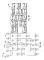
- FIG. 4Ashows a resistive network model 400 for an energy director configuration including six (6) bipolar energy directors, under the embodiment of FIGS. 2 and 3 .
- Each of the six bipolar energy directorsis represented by one of nodes 1 – 6 , wherein each node is assigned an alternating polarity 499 , but the polarity assigned in this example is not limiting.
- the model 400includes a number of resistors R 1 –R 19 coupled in various configurations among nodes 1 – 6 and current source 402 , as described further below.
- the current source 402is arbitrarily selected to produce 750 milliamps (mA) of current, but the model is not so limited.
- the resistor configurations of the model 400simulate the relative power dissipation, including the coupling effects among the various combinations of alternating polarity nodes, in the tissue volumes (“zones”) between the energy directors (nodes), as further described below.
- tissue volumeszones
- the resistor values of the modelare iteratively varied to represent different channel spacing.
- resistor RImodels the power dissipation in zone 1 as a result of current flowing between nodes 1 and 2 .
- resistors R 2 , R 3 , R 4 , and R 5each model the power dissipation as a result of current flowing between the nodes that define each of zones 2 – 5 , respectively.
- the series combination of resistors R 6 , R 7 , and R 8couple between nodes 1 and 4 and model the power dissipation across zones 1 , 2 , and 3 as a result of the current flowing between nodes 1 and 4 .
- the series combination of resistors R 9 , R 10 , and R 11couple between nodes 3 and 6 and model the power dissipation across zones 3 , 4 , and 5 as a result of the current flowing between these nodes.
- the series combination of resistors R 12 , R 13 , and R 14couple between nodes 2 and 5 and model the power dissipation across zones 2 , 3 , and 4 as a result of the current flowing between nodes 2 and 5 .
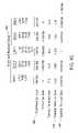
- FIG. 4Bshows a table 450 including power dissipation values corresponding to an energy director configuration providing balanced energy, under the embodiment of FIG. 4A .
- FIG. 4Cis a table 480 including power dissipation and spacing information corresponding to an energy director configuration providing balanced energy, under the embodiment of FIG. 4A .
- This table 480includes total power dissipation 482 for each zone of the resistive network model 400 .
- the balanced energy director configurationuses non-uniform channel spacing in the energy director guide to account for the effects of electromagnetic coupling, as described above, under the embodiment of FIG. 2 .
- the resistor values for the zones of an arrayare varied iteratively until the total power dissipation per zone 482 is approximately equal; the spacing per zone is proportional to the resistor values.
- the total power dissipation across zones 1 – 5 in a balanced energy director configurationis approximately 246 milliwatts (mW), 248 mW, 250 mW, 248 mW, and 246 mW, respectively, but is not so limited. Consequently, the power dissipation or distribution across the zones is approximately uniform.
- spacing ratios per zone 484 and 486are generated.
- two different spacing ratios per zone 484 and 486are generated, but the embodiment is not so limited.
- a first spacing ratio per zone 484references the spacing of the zones to the proximal-most/distal-most zones (zones 1 and 5 ) of the array, and a second spacing ratio per zone 486 references the spacing of the zones to the center zone (zone 3 ) of the array. Note, however, that the spacing ratios per zone can be referenced to any zone of the array in alternative embodiments.
- the relative spacing among the channelsis determined by assigning a reference spacing value to the reference zone (the zone for which the spacing ration is one (1)).
- the spacing values for all other zones of the arrayare then each determined using the spacing ratio for each associated zone as a multiplier against the reference spacing value.
- Reference spacing valuesare selected using techniques known in the art, wherein the largest spacing value between the energy directors of an array is approximately in the range of 0.75 cm to 2.00 cm, but the embodiment is not so limited.
- tissue ablation systeminclude differing numbers of energy directors and, therefore, differing numbers of channels in the energy director guide.
- one alternative embodimentincludes an energy director guide having a series of eight (8) channels that receive energy directors of alternating polarity.
- the channel spacing in this alternative embodimentis also determined using a resistive network model simulation, but is not so limited.
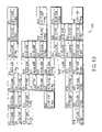
- FIG. 5Ashows a resistive network model 500 for an energy director configuration including eight (8) bipolar energy directors, under an alternative embodiment.
- the energy director guide of this exampleincludes eight (8) channels, each of which receive an energy director.
- Each of the eight bipolar energy directorsis represented by one of nodes 1 – 8 , wherein each node is assigned an alternating polarity.
- the model 500includes a number of resistors R 1 –R 44 coupled in various configurations among nodes 1 – 8 and current source 502 , as described further below.
- the current source 502is arbitrarily selected to produce one (1) amp of current, but the model is not so limited.
- resistor RImodels the power dissipation as a result of current flowing between nodes 1 and 2 .
- resistors R 2 , R 3 , R 4 , R 5 , R 6 , and R 7each model the power dissipation as a result of current flowing between the nodes that define each of zones 2 – 7 , respectively.
- the series combination of resistors R 8 , R 9 , and R 10couple between nodes 1 and 4 and model the power dissipation across zones 1 , 2 , and 3 as a result of the current flowing between nodes 1 and 4 .
- resistors R 11 , R 12 , R 13 , R 14 , and R 15couple between nodes 1 and 6 and model the power dissipation across zones 1 , 2 , 3 , 4 , and 5 as a result of the current flowing between nodes 1 and 6 .
- the series combination of resistors R 16 , R 17 , and R 18couple between nodes 3 and 6 and model the power dissipation across zones 3 , 4 , and 5 as a result of the current flowing between nodes 3 and 6 .
- the series combination of resistors R 19 , R 20 , R 21 , 22 , and R 23couple between nodes 3 and 8 and model the power dissipation across zones 3 , 4 , 5 , 6 , and 7 as a result of the current flowing between nodes 3 and 8 .
- the series combination of resistors R 24 , R 25 , and R 26couple between nodes 2 and 5 and model the power dissipation across zones 2 , 3 , and 4 as a result of the current flowing between nodes 2 and 5 .
- the series combination of resistors R 27 , R 28 , and R 29couple between nodes 5 and 8 and model the power dissipation across zones 5 , 6 , and 7 as a result of the current flowing between nodes 5 and 8 .
- the series combination of resistors R 30 , R 31 , and R 32couple between nodes 4 and 7 and model the power dissipation across zones 4 , 5 , and 6 as a result of the current flowing between nodes 4 and 7 .
- the series combination of resistors R 33 , R 34 , R 35 , R 36 , and R 37couple between nodes 2 and 7 and model the power dissipation across zones 2 , 3 , 4 , 5 , and 6 as a result of the current flowing between nodes 2 and 7 .
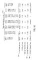
- FIG. 5Bshows a table 550 including power dissipation values corresponding to an energy director configuration providing balanced energy, under the embodiment of FIG. 5A .
- FIG. 5Cis a table 580 including power dissipation information 582 and spacing information 584 and 586 corresponding to an energy director configuration providing balanced energy, under the embodiment of FIG. 5A .
- This power dissipation table 580includes total power dissipation 582 for each zone of the resistive network model 500 .
- the balanced energy director configurationuses non-uniform channel spacing in the energy director guide to account for the effects of electromagnetic coupling, as described above.
- the total power dissipation across zones 1 – 7is approximately 563 mW, 565 mW, 564 mW, 567 mW, 564 mW, 565 mW, and 563 mW, respectively. Consequently, the power dissipation or distribution across the zones is approximately uniform.
- the embodiments described above with reference to FIGS. 2 , 3 , 4 , and 5provide approximately uniform power distribution among the tissue zones of a target tissue volume.
- alternative embodiments of the energy director arrayare configured to provide approximately uniform current density through the target tissue volume.
- the tissue ablation systems of various alternative embodimentsgenerate avascular volumes of coagulated tissue using approximately uniform current,density.
- the energy director guide channel spacing that provides uniform current densityis determined using resistive network models, as above, but is not so limited.
- FIG. 6Ashows a resistive network model 600 for an energy director configuration including six (6) bipolar energy directors, under an alternative embodiment of FIGS. 2 and 3 .
- Each of the six bipolar energy directorsis represented by one of nodes 1 – 6 , wherein each node is assigned an alternating polarity.
- the model 600includes a number of resistors R 1 –R 19 coupled in various configurations among nodes 1 – 6 and current source 602 , as described above with reference to FIG. 4A .
- the relative power dissipation among the different zonesis proportional to the current density in the associated tissue zones.
- the current source 602is arbitrarily selected to produce 750 milliamps (mA) of current, but the model is not so limited.
- FIG. 6Bshows a table 650 including power dissipation information corresponding to an energy director configuration providing balanced energy, under the embodiment of FIG. 6A .
- FIG. 6Cis a table 680 including current density and spacing information corresponding to an energy director configuration that provides balanced energy, under the embodiment of FIG. 6A .
- This table 680includes the current density per zone 682 for the zones of the resistive network model 600 .
- the balanced energy director configurationuses non-uniform channel spacing in the energy director guide to account for the effects of electromagnetic coupling, as described above.
- the resistor values for the zones of an arrayare varied iteratively until the current density per zone 682 is approximately equal; the channel spacing information is proportional to and derived from the final resistor values that provide approximately uniform current density.
- the current density per zone across zones 1 – 5is approximately 15.85 milliamps (mA)/spacing value, 15.8446 mA/spacing value, 15.80769 mA/spacing value, 15.8446 mA/spacing value, and 15.85 mA/spacing value, respectively, but is not so limited. Consequently, the current density across the zones is approximately uniform.
- spacing ratios per zone 684 and 686are generated. In an embodiment, two different spacing ratios per zone 684 and 686 are generated, but the embodiment is not so limited.
- a first spacing ratio per zone 684references the spacing of the zones to the proximal-most/distal-most zones (zones 1 and 5 ) of the array, and a second spacing ratio per zone 686 references the spacing of the zones to the center zone (zone 3 ) of the array. Note, however, that the spacing ratios per zone can be referenced to any zone of the array in alternative embodiments.
- the relative spacing among the channelsis determined by assigning a reference spacing value to the reference zone (the zone for which the spacing ration is one (1)).
- the spacing values for all other zones of the arrayare then each determined using the spacing ratio for each associated zone as a multiplier against the reference spacing value.
- Reference spacing valuesare selected using techniques known in the art.
- Alternative embodiments of the tissue ablation systeminclude differing numbers of energy directors and, therefore, differing numbers of channels in the energy director guide. As described above, the channel spacing in these alternative embodiments is also determined using a resistive network model simulation, but is not so limited.
- the energy director guide of an alternative embodimentis reconfigurable to support a number of energy director configurations.
- the energy director guidecan include channels that are moveable between a number of prespecified locations in the energy director guide so that placement of the channels in a first set of prespecified locations along the guide supports the six energy guide configuration described above, and placement of the channels in a second set of prespecified locations along the guide supports the eight energy guide configuration described above.
- a usercan support many different energy director configurations with a single energy director guide.
- the energy director guide of an embodimentindependently couples each of the energy directors to the generator via the energy director guide. Further, the energy director guide independently secures a position of each of the energy directors in the target tissue.
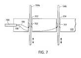
- FIG. 7is a side view of an energy director guide 102 using direct coupling, under an embodiment.
- Each channel 202 and 204 of the guide 102includes one or more contacts 702 and 704 that couple conductors 706 and 708 of an energy conduit 799 from the generator (not shown) directly to the corresponding energy director 104 a and 104 b .
- a first conductor 706 carrying signals of a first polaritycouples to a first energy director 104 a via a first contact 702 .
- a second conductor 708 carrying signals of a second polaritycouples to a second energy director 104 b via a second contact 704 .
- the contacts of an embodimentare fabricated from materials with good spring and wear properties including, for example, stainless steel and beryllium copper.
- the contacts of alternative embodimentscan also secure or assist in securing a position of the energy directors, but are not so limited.
- FIG. 8is a schematic of a circuit board 800 for use in an energy director guide, under the embodiment of FIG. 2 .
- the circuit board 800directly couples power signals having the appropriate polarity from a power source to the corresponding channels, and thus the corresponding energy directors, via conducting traces 802 and 804 .
- a first conducting trace 802carries an electrical signal having a first polarity, for example a positive polarity, among the energy directors of channels 202 , 206 , and 210 .
- a second conducting trace 804carries an electrical signal having a second polarity, for example a negative polarity, among the energy directors of channels 204 , 208 , and 212 , but the embodiment is not so limited.
- FIG. 9is a side view of a guide 102 using indirect coupling, under an embodiment.
- Each channel 202 and 204 of the guide 102includes a coil or winding of conductive material 902 and 904 that indirectly couples conductors 912 and 914 of an energy conduit 999 from the power source (not shown) to the corresponding energy director 104 a – 104 b.
- FIG. 10shows a guide 102 that provides for independent control of the insertion depth of each energy director 1002 , under an embodiment.
- the guide 102provides independent control of the insertion of each energy director 1002 to independently variable depths within the target tissue.
- the insertion of the energy directors 1002can be performed individually or simultaneously as appropriate to the procedure. As such, each energy director 1002 can be inserted into the target tissue to a different depth, thereby allowing the physician or clinician to avoid critical anatomical structures with the application of RF energy. This is particularly valuable since there often are present critical anatomical structures into which an energy director 1002 should not be inserted.
- independent control of insertion depth for each energy director 1002supports the use of various visualization methods such as ultrasound stenography, Computerized Tomography (CT), and Magnetic Resonance Imaging (MRI) in placement of the energy directors 1002 in target tissue.
- CTComputerized Tomography
- MRIMagnetic Resonance Imaging
- components of the energy director guideexert enough force on the corresponding energy directors to secure them in the target tissue so that natural body movement will not push the energy directors out.
- the components of the energy director guideexert a force on the energy directors approximately in the range of 0.5 newton to 5 newton, but are not so limited.
- FIG. 11shows operation of the tissue ablation system to generate an avascular volume of tissue, under the embodiment of FIG. 2 .
- the ablation procedurebegins by positioning the energy directors 1104 at a first depth in the target tissue 199 .
- the depth shownis exemplary only, and is not a limiting depth.
- the first depth at which the energy directors 1104 are placedis not limited to a particular depth except by the length of the energy directors 1104 used in a particular procedure or the anatomical structures present in the target tissue.
- the userapplies power to the positioned energy directors 1104 , thereby ablating the corresponding volume 1110 of engaged target tissue.
- the tissue ablation systemcan be used to incrementally ablate a volume of target tissue as the energy directors 1104 are incrementally advanced into the target tissue.
- FIG. 12shows operation of the tissue ablation system to generate an avascular volume of tissue, under an alternative embodiment of FIG. 11 .
- the energy directors 1104are further advanced to a second depth in the target tissue 199 .
- the usercouples the power to the energy directors 1104 , thereby ablating the corresponding increased volume 1210 of engaged target tissue.
- Advancement of the energy directors 1104continues until the entire desired volume of issue is rendered avascular or near-avascular.
- the shape and size of the ablation volume 1110 and 1210is controlled by the configuration of the electrode cluster, the geometry of he exposed energy director tips, the amount of power applied, the time duration that the power is applied, and cooling of the electrodes, to name a few.
- This methodis particularly useful to help control several critical parameters including energy density, thermal load from the surrounding tissue, and the electrical impedance of the tissue.
- energy densityis too low the thermal effect cannot be achieved.
- thermal load from the surrounding tissueis too large the thermal effect will also not be achieved.
- Low electrical tissue impedancemakes it difficult to heat since the dissipated power is proportional to the tissue impedance. Very low or high impedance will also be difficult for some power supplies to deliver the required energy.
- FIG. 13is a flow diagram for the operation of the tissue ablation system, under the embodiments of FIG. 1 , FIG. 11 , and FIG. 12 .
- a userselects an appropriate configuration of the energy directors, at block 1302 .
- This selectionincludes, for example, determinations as to the following factors: (i) the number of energy directors in the cluster; (ii) the relative geometry, individual size, and tip exposure of the energy directors; (iii) the geometry of the target tissue region and identification of any tissue regions to be avoided; and (iv) selecting cooled or non cooled electrodes.
- the selectioncan include processing image scan data from a CT scan, MRI, ultrasound, and/or other type of scanning device to determine the position of a targeted volume such as a tumor within the patient's body and the desired approach, placement, size, and number of energy directors.
- the positioning of the energy directors in an embodimentis preplanned, for example using a workstation, and the heat isotherms and ablation volume and time-course of the ablation are determined. Based on historical or empirical information, the user may determine the desired power to be delivered to the tissue, the temperature as measured by the electrode or measured elsewhere in the tissue by either integrated temperature sensors in the energy directors or satellite temperature-sensing electrodes, the desired time duration of heating, and the characteristics of impedance, to determine energy application timing parameters and control against charring and other undesired effects.
- the selection of an embodimentincludes sizing of the electrodes based on the target organ. For example, the user can estimate a transverse dimension of the target organ. Using the estimated dimension, the user sizes the electrodes individually or as a group so that the electrodes do not extend beyond the target organ when fully inserted in the target organ.
- the userpositions the energy director guide, and inserts the electrodes into the target tissue, at block 1304 .
- the energy directorscan be placed individually or in unison within the body tissue, as described herein. Real-time imaging can be used, for example CT, MRI, and/or ultrasound, during placement of the electrodes to determine their proper position within a targeted volume of tissue.
- the userinserts the energy directors to a desired depth. Additionally, if the energy directors are used with coolant, the user applies the coolant as appropriate.
- the userseparates the target organ from one or more adjacent organs, but the embodiment is not so limited. This is done to prevent the electrodes from piercing the adjacent organs upon or during insertion into the target organ. Alternatively, the user can place a shield between the target organ and any adjacent organs to protect the adjacent organs from penetration by the electrodes.
- the usercouples or applies power from the generator to the energy director guide and the energy directors, at block 1306 .
- the poweris coupled directly to the energy directors. While power is described in this example, various alternative embodiments can, instead of using power as the controlling parameter, use current, voltage, impedance, temperature, time, and/or any combination of these, to control the tissue ablation process.
- the powercan be coupled to all of the energy directors in unison, or sequentially in a predetermined sequence, as appropriate to the treatment procedure and/or the target tissue type. Likewise, the insertion depth of the energy directors and the amount of power coupled to the energy directors is varied according to the treatment procedure and/or the target tissue type.
- the application of powercan be controlled either automatically or manually.
- the processcan be controlled according to a microprocessor control within the generator system itself or by at least one separate controller coupled among the components of the tissue ablation system.
- the application of power to the energy directorscan be controlled in response to measurements of temperature, impedance, and/or other feedback parameters associated with the ablation process.
- the temperatureis increased at a rate approximately in the range of 25 degrees Celsius/minute to 100 degrees Celsius/minute to a temperature endpoint in the target tissue that is approximately in the range of 55 degrees Celsius to 110 degrees Celsius, but is not so limited.
- tissue temperature25–100 degrees Celsius/minute
- the highly conductive fluid inside the cellsis released. This lowers the impedance around the energy director helping to prevent charring and allowing the continued (or increasing) flow of energy to the target tissue. This release is caused by the thermal damage to the cell wall. If the energy rise is too quick, the fluid will be quickly boiled or flashed off. This will result in no significant benefit and help to increase the tendency for tissue charring and a loss of ability to deliver energy to the target tissue.
- the energy director temperatures or temperatures from satellite probes within and/or within proximity of the target tissuecan be monitored. When the monitored temperatures remain within acceptable levels, the power can be increased or the flow of coolant modified.
- Coupling power to the energy director guide/energy directors, at block 1306results in generation of a plane of coagulated tissue in the target tissue, at block 1308 .
- a prespecified period of time for the application of power to the energy directorsdetermines when the plane of coagulated tissue has been generated. Therefore, when the prespecified period of time elapses, the user stops the procedure. As described above, feedback of additional information can be used to determine successful completion of the procedure. Various portions of the procedure can be repeated, as appropriate to the target tissue, until the plane of coagulated tissue having the appropriate size and shape is generated, at block 1310 .
- tissue ablation system and associated processes described abovecan include other components in a variety of combinations.
- a stereotactic frame or frameless navigator systemmay be used to direct and place the energy director guide/energy directors.
- Various guide tubes, templates, holding apparatus, arc systems, and spatial digitizerscan also be used to assist in placement of the energy directors in the target tissue.
- Imaging modalitiessuch as CT, MRI, ultrasound and the like can be used before, during, or after placement of the energy directors and/or creation of the ablation volume.
- tissue ablation system componentsIn addition to including numerous types and combinations of components, there are many alternative embodiments of the tissue ablation system components described above. Some of these alternatives include alternative embodiments of the energy director guide and the energy directors, as described below.
- the energy director guide of one alternative embodimentincludes a soft conformal bottom element that forms a conformal surface between the target tissue and the energy director guide.
- the conformal elementtakes on the shape of the surface of the underlying target tissue.
- Conformal bottom elementscan be constructed from a variety of materials including silicone, biocompatible foam rubbers, and urethanes. Conformal bottom elements can also be formed with the use of inflated members.
- the energy director guide of various alternative embodimentsmay take on a variety of shapes including, but not limited to, semi-circular, arcs, and angles. Many other shapes will be recognized by those skilled in the art.
- FIG. 14shows a flexible or semi-flexible guide 1402 , under an embodiment.
- This flexible guide 1402provides flexibility in two planes.
- FIG. 15shows a flexible or semi-flexible guide 1502 , under another alternative embodiment, that provides flexibility in one plane.
- These guides 1402 and 1502while being configured to secure and couple power to the energy directors as described above with reference to FIGS. 2 , 3 , 7 , 8 , and 9 , permit the user to alter the guide within limits to create a desired shape which, in turn, allows the resulting coagulation plane to match the desired outcome or avoid critical anatomical structures.
- desired shapes including curved portionsare formed from a series of coagulation planes having various dimensions, but the embodiment is not so limited.
- These guidescan be flexible or semi-flexible in a single or multiple planes.
- the guideIn a single plane, the guide can be shaped to the tissue targeted below the guide. With a second plane of flexibility, the guide can be used to contour to the shape of the surface or as necessary for location of the operative site.
- FIG. 16is an energy director array including a joining member 1602 that provides for simultaneous insertion or retraction of energy directors 1604 into target tissue, under an embodiment.
- the energy directorsare connected to the joining member 1602 to allow for the simultaneous insertion or retraction of all energy directors 1604 via the energy director guide.
- all energy directors 1604can be of the same length, thereby allowing the simultaneous insertion of all energy directors 1604 to a desired depth within the tissue. This is of benefit when a full thickness ablation plane is desired, there are no anatomical structures that would be contraindicated for the energy directors, and ease of use is important.
- FIG. 17is an energy director array including a joining member 1702 connected to energy directors 1704 , under an alternative embodiment.
- Select energy directors 1704have non-uniform lengths as they are tailored to match the thickness and shape of the target tissue or organ and/or to avoid critical anatomical structures.
- the joining member 1702therefore, supports the simultaneous insertion and withdrawal of all energy directors regardless of length while also supporting the avoidance of critical anatomical structures by the energy directors 1704 .
- the energy directors of an embodimentcan be used with a variety of housings that enclose the energy directors prior to deployment into target tissue. Use of the housing minimizes unintentional deployment of the energy directors and reduces the potential for injury of a user or patient by the energy directors.
- FIG. 18shows energy directors 1802 , 1804 , and 1806 supporting delivery of various agents into the target tissue, under an embodiment.
- One type of energy director 1802supports delivery of agents through a lumen in the energy director and apertures 1812 around the outer surface of the energy director 1802 .
- Another type of energy director 1804supports delivery of agents through a lumen in the energy director and at least one aperture 1814 in the distal end of the energy director 1804 .
- Yet another type of energy director 1806supports delivery of agents through a lumen in the energy director in communication with a porous material 1816 around the outer surface of the energy director 1806 .
- the energy directors 1802 , 1804 , and 1806support deliver of agents including, but not limited to, contrast agents used to better visualizes the detailed anatomy, sclerotic agents to help decrease the overall circulation in the target region, and chemotherapy agents for use as an adjunctive therapy.
- agentsincluding, but not limited to, contrast agents used to better visualizes the detailed anatomy, sclerotic agents to help decrease the overall circulation in the target region, and chemotherapy agents for use as an adjunctive therapy.
- Still another example agentis a hyper- or hypo-tonic solution used to create a wet electrode.
- FIG. 19shows energy directors 1904 that capacitively couple to target tissue, under an embodiment.
- the energy directors 1904are fully, or near-fully insulated.
- An example of this configurationincludes one or more conducting cores 1906 suitable for conducting energy, where the conducting core 1906 is fully or near fully insulated with an appropriate dielectric material 1908 , coating, or sleeve.
- the thickness of coating 1908varies according to the dielectric properties of the material used as the electrical insulator. Coating thicknesses of the various embodiments range from approximately 0.00005 inch to 0.001 inch, but are not so limited.
- the energy directors 1904induce an energy flow into the target tissue. When appropriately applied, this energy would then cause the target tissue to heat and coagulate, as described above.
- the use of capacitive coupling in this formcan increase the relatively low electrical impedance that results when several energy directors 1904 are used at a relatively close spacing.
- the tissue ablation system of an embodimentincludes one or more energy directors that support temperature monitoring within and/or around the target tissue.
- the temperature monitoring supported by the energy directorssupports the real-time evaluation of an ablation procedure both outside and within the effected tissue zone.
- An example of thiscould be one or more thermocouples arranged in a configuration suitable for placement within the tissue, for example on and/or within an associated energy director, wherein the thermocouples couple to temperature monitoring equipment known in the art.
- the tissue ablation system and associated procedures of an embodimentdeliver energy that results in tissue core temperatures approximately in the range between 65 degrees Celsius and 80 degrees Celsius in the coldest portions of the target tissue volume.
- the coldest portions of the target tissue volumeare typically those areas that are the most distant from the energy directors or are thermally shielded from the effect of the energy directors by other anatomical structures.
- tissue ablation system and associated proceduresdeliver energy that results in tissue core temperatures approximately in the range between 85 degrees Celsius and 105 degrees Celsius in the warmest portions of the target tissue volume. At temperatures below this, procedural times may be unnecessarily extended. At temperatures above this, instability may result due to the superficial charring caused by the excessive tissue heating. As noted herein, these conditions can be further mitigated with the use of other factors such has hypertonic agents. In particular, a continuous infusion of a 0.9% to 8% saline solution at an approximate rate of between 0.01 cc/min to 0.5 cc/min will aid in preventing tissue charring.
- the temperature monitoring energy directorprovides the ability to control the energy delivered to the target tissue by controlling the energy with the use of a closed- or open-loop temperature feedback system. As such, optimum energy delivery can be achieved, thereby avoiding over delivery or under delivery of energy. Over delivery of energy can create superficially charred tissue resulting in a reduction or inability to deliver energy and an incomplete ablation. Under delivery of energy could significantly increase the procedural duration or even prevent the ability to complete the procedure. By controlling the transfer of energy to the target tissue in this manner, and by using non-stick surfaces such as fluoropolymers like polypropelene and parylene on the energy directors, charring can be minimized to produce optimal energy delivery and tissue ablation. In addition, the use of temperature monitoring also provides evidence and feedback as to the completion of the procedure, as described above.
- the energy director guide of an embodimentconfigures the energy directors to provide approximately uniform power or energy distribution through the target tissue volume.
- Alternative embodiments of the tissue ablation systemsupport the application of non-uniform energy distribution via either linear or non-linearly spaced arrays. This configuration monitors a parameter such as temperature, power, or impedance and, in response, controls the delivered energy to maintain the parameter(s) within a desired target range. By using individual energy channels for each bipolar pair, the energy can easily be altered as needed.
- the time-temperature slopesare evaluated for each zone based on a predetermined ramp (approximately in the range of 50–80 degrees Celsius/minute). Based on the temperature ramp the power is altered to better match the desired rate.
Landscapes
- Health & Medical Sciences (AREA)
- Surgery (AREA)
- Engineering & Computer Science (AREA)
- Life Sciences & Earth Sciences (AREA)
- Biomedical Technology (AREA)
- Otolaryngology (AREA)
- Nuclear Medicine, Radiotherapy & Molecular Imaging (AREA)
- Plasma & Fusion (AREA)
- Physics & Mathematics (AREA)
- Heart & Thoracic Surgery (AREA)
- Medical Informatics (AREA)
- Molecular Biology (AREA)
- Animal Behavior & Ethology (AREA)
- General Health & Medical Sciences (AREA)
- Public Health (AREA)
- Veterinary Medicine (AREA)
- Surgical Instruments (AREA)
Abstract
Description
Claims (28)
Priority Applications (12)
| Application Number | Priority Date | Filing Date | Title |
|---|---|---|---|
| US10/413,112US7008421B2 (en) | 2002-08-21 | 2003-04-14 | Apparatus and method for tissue resection |
| AU2003249061AAU2003249061B2 (en) | 2002-08-21 | 2003-07-11 | Apparatus and method for tissue resection |
| EP03792964.3AEP1531748B1 (en) | 2002-08-21 | 2003-07-11 | Apparatus for tissue resection |
| JP2004530820AJP2005536278A (en) | 2002-08-21 | 2003-07-11 | Tissue excision apparatus and excision method |
| CA002495791ACA2495791A1 (en) | 2002-08-21 | 2003-07-11 | Apparatus and method for tissue resection |
| PCT/US2003/021766WO2004017851A1 (en) | 2002-08-21 | 2003-07-11 | Apparatus and method for tissue resection |
| US10/800,451US7223264B2 (en) | 2002-08-21 | 2004-03-15 | Thermal coagulation of tissue during tissue resection |
| US10/890,055US7341586B2 (en) | 2002-08-21 | 2004-07-12 | Thermal coagulation of tissue during tissue resection |
| US11/256,500US20060100620A1 (en) | 2002-08-21 | 2005-10-20 | Thermal hemostasis and/or coagulation of tissue |
| US11/335,295US8986297B2 (en) | 2002-08-21 | 2006-01-18 | Thermal hemostasis and/or coagulation of tissue |
| US11/335,092US20060142757A1 (en) | 2002-08-21 | 2006-01-18 | Apparatus and method for tissue resection |
| US11/605,905US20080125775A1 (en) | 2001-02-28 | 2006-11-28 | Hemostasis and/or coagulation of tissue |
Applications Claiming Priority (2)
| Application Number | Priority Date | Filing Date | Title |
|---|---|---|---|
| US40505102P | 2002-08-21 | 2002-08-21 | |
| US10/413,112US7008421B2 (en) | 2002-08-21 | 2003-04-14 | Apparatus and method for tissue resection |
Related Child Applications (4)
| Application Number | Title | Priority Date | Filing Date |
|---|---|---|---|
| US09/797,409Continuation-In-PartUS7422586B2 (en) | 2001-02-28 | 2001-02-28 | Tissue surface treatment apparatus and method |
| PCT/US2003/021766Continuation-In-PartWO2004017851A1 (en) | 2002-08-21 | 2003-07-11 | Apparatus and method for tissue resection |
| US10/800,451Continuation-In-PartUS7223264B2 (en) | 2002-08-21 | 2004-03-15 | Thermal coagulation of tissue during tissue resection |
| US11/335,092ContinuationUS20060142757A1 (en) | 2002-08-21 | 2006-01-18 | Apparatus and method for tissue resection |
Publications (2)
| Publication Number | Publication Date |
|---|---|
| US20040039429A1 US20040039429A1 (en) | 2004-02-26 |
| US7008421B2true US7008421B2 (en) | 2006-03-07 |
Family
ID=31946989
Family Applications (2)
| Application Number | Title | Priority Date | Filing Date |
|---|---|---|---|
| US10/413,112Expired - LifetimeUS7008421B2 (en) | 2001-02-28 | 2003-04-14 | Apparatus and method for tissue resection |
| US11/335,092AbandonedUS20060142757A1 (en) | 2002-08-21 | 2006-01-18 | Apparatus and method for tissue resection |
Family Applications After (1)
| Application Number | Title | Priority Date | Filing Date |
|---|---|---|---|
| US11/335,092AbandonedUS20060142757A1 (en) | 2002-08-21 | 2006-01-18 | Apparatus and method for tissue resection |
Country Status (2)
| Country | Link |
|---|---|
| US (2) | US7008421B2 (en) |
| WO (1) | WO2004017851A1 (en) |
Cited By (97)
| Publication number | Priority date | Publication date | Assignee | Title |
|---|---|---|---|---|
| US20020120260A1 (en)* | 2001-02-28 | 2002-08-29 | Morris David L. | Tissue surface treatment apparatus and method |
| US20050143795A1 (en)* | 1998-08-05 | 2005-06-30 | Imperial College Innovations Limited | Applicator for microwave radiation treatment |
| US20050171534A1 (en)* | 2003-09-29 | 2005-08-04 | Emcision Limited | Surgical resection device |
| US20050222565A1 (en)* | 2004-04-01 | 2005-10-06 | Dieter Manstein | Method and apparatus for dermatological treatment and tissue reshaping |
| US20060025761A1 (en)* | 2004-07-29 | 2006-02-02 | Riley Lee B | Linear-array radio frequency resections |
| US20060079885A1 (en)* | 2004-10-08 | 2006-04-13 | Rick Kyle R | Cool-tip combined electrode introducer |
| US20060224152A1 (en)* | 2005-03-31 | 2006-10-05 | Sherwood Services Ag | Method and system for compensating for external impedance of an energy carrying component when controlling an electrosurgical generator |
| US20070129726A1 (en)* | 2005-05-12 | 2007-06-07 | Eder Joseph C | Electrocautery method and apparatus |
| US20070135812A1 (en)* | 2005-12-12 | 2007-06-14 | Sherwood Services Ag | Laparoscopic apparatus for performing electrosurgical procedures |
| US20070173806A1 (en)* | 2006-01-24 | 2007-07-26 | Sherwood Services Ag | System and method for closed loop monitoring of monopolar electrosurgical apparatus |
| US20070173804A1 (en)* | 2006-01-24 | 2007-07-26 | Wham Robert H | System and method for tissue sealing |
| US20080091185A1 (en)* | 2006-10-16 | 2008-04-17 | Primaeva Medical, Inc. | Methods and devices for treating tissue |
| US20080091184A1 (en)* | 2006-10-16 | 2008-04-17 | Primaeva Medical, Inc. | Methods and devices for treating tissue |
| US20080091182A1 (en)* | 2006-10-16 | 2008-04-17 | Primaeva Medical. Inc. | Methods and devices for treating tissue |
| US20080091183A1 (en)* | 2006-10-16 | 2008-04-17 | Primaeva Medical, Inc. | Methods and devices for treating tissue |
| US20080248685A1 (en)* | 2003-11-20 | 2008-10-09 | Joe Don Sartor | Connector Systems for Electrosurgical Generator |
| US20080269734A1 (en)* | 2007-04-26 | 2008-10-30 | Agustina Vila Echague | Optical Array for Treating Biological Tissue |
| US20080281315A1 (en)* | 1997-04-09 | 2008-11-13 | David Lee Gines | Electrosurgical Generator With Adaptive Power Control |
| US20080281389A1 (en)* | 2006-10-16 | 2008-11-13 | Primaeva Medical Inc. | Methods and devices for treating tissue |
| US20090036882A1 (en)* | 2002-06-10 | 2009-02-05 | Webster John G | Circumferential electrode array for tissue ablation |
| US20090070090A1 (en)* | 2004-12-23 | 2009-03-12 | Stanley Humphries | Three-Dimensional Finite-Element Code for Electerosurgery and Thermal Ablation Simulations |
| US20090076496A1 (en)* | 2007-09-14 | 2009-03-19 | Lazure Technologies Llc. | Prostate cancer ablation |
| US7537595B2 (en) | 2001-12-12 | 2009-05-26 | Tissuelink Medical, Inc. | Fluid-assisted medical devices, systems and methods |
| US20090138004A1 (en)* | 2007-11-27 | 2009-05-28 | Vivant Medical, Inc. | System and Method for Field Ablation Prediction |
| US20090153421A1 (en)* | 2007-12-12 | 2009-06-18 | Ahmadreza Rofougaran | Method and system for an integrated antenna and antenna management |
| US7604635B2 (en) | 2000-03-06 | 2009-10-20 | Salient Surgical Technologies, Inc. | Fluid-assisted medical devices, systems and methods |
| US7645277B2 (en) | 2000-09-22 | 2010-01-12 | Salient Surgical Technologies, Inc. | Fluid-assisted medical device |
| US7651492B2 (en) | 2006-04-24 | 2010-01-26 | Covidien Ag | Arc based adaptive control system for an electrosurgical unit |
| US7682375B2 (en) | 2002-05-08 | 2010-03-23 | Stephen Ritland | Dynamic fixation device and method of use |
| US7727232B1 (en) | 2004-02-04 | 2010-06-01 | Salient Surgical Technologies, Inc. | Fluid-assisted medical devices and methods |
| US20100256735A1 (en)* | 2009-04-03 | 2010-10-07 | Board Of Regents, The University Of Texas System | Intraluminal stent with seam |
| US7811282B2 (en) | 2000-03-06 | 2010-10-12 | Salient Surgical Technologies, Inc. | Fluid-assisted electrosurgical devices, electrosurgical unit with pump and methods of use thereof |
| US7815634B2 (en) | 2000-03-06 | 2010-10-19 | Salient Surgical Technologies, Inc. | Fluid delivery system and controller for electrosurgical devices |
| US7834484B2 (en) | 2007-07-16 | 2010-11-16 | Tyco Healthcare Group Lp | Connection cable and method for activating a voltage-controlled generator |
| US7901400B2 (en) | 1998-10-23 | 2011-03-08 | Covidien Ag | Method and system for controlling output of RF medical generator |
| US20110066144A1 (en)* | 2009-09-16 | 2011-03-17 | Vivant Medical, Inc. | Perfused Core Dielectrically Loaded Dipole Microwave Antenna Probe |
| US20110077631A1 (en)* | 2009-09-28 | 2011-03-31 | Tyco Healthcare Group Lp | Electrosurgical Generator User Interface |
| US20110118731A1 (en)* | 2009-11-16 | 2011-05-19 | Tyco Healthcare Group Lp | Multi-Phase Electrode |
| US7951148B2 (en) | 2001-03-08 | 2011-05-31 | Salient Surgical Technologies, Inc. | Electrosurgical device having a tissue reduction sensor |
| US7972332B2 (en) | 2006-03-03 | 2011-07-05 | Covidien Ag | System and method for controlling electrosurgical snares |
| US7998140B2 (en) | 2002-02-12 | 2011-08-16 | Salient Surgical Technologies, Inc. | Fluid-assisted medical devices, systems and methods |
| US8025660B2 (en) | 2004-10-13 | 2011-09-27 | Covidien Ag | Universal foot switch contact port |
| US8062290B2 (en) | 2004-10-08 | 2011-11-22 | Covidien Ag | Electrosurgical system employing multiple electrodes |
| US8080008B2 (en) | 2003-05-01 | 2011-12-20 | Covidien Ag | Method and system for programming and controlling an electrosurgical generator system |
| US8096961B2 (en) | 2003-10-30 | 2012-01-17 | Covidien Ag | Switched resonant ultrasonic power amplifier system |
| US8105323B2 (en) | 1998-10-23 | 2012-01-31 | Covidien Ag | Method and system for controlling output of RF medical generator |
| US8147485B2 (en) | 2006-01-24 | 2012-04-03 | Covidien Ag | System and method for tissue sealing |
| US8187262B2 (en) | 2006-01-24 | 2012-05-29 | Covidien Ag | Dual synchro-resonant electrosurgical apparatus with bi-directional magnetic coupling |
| US8216223B2 (en) | 2006-01-24 | 2012-07-10 | Covidien Ag | System and method for tissue sealing |
| US8216220B2 (en) | 2007-09-07 | 2012-07-10 | Tyco Healthcare Group Lp | System and method for transmission of combined data stream |
| US8221459B2 (en) | 2002-02-20 | 2012-07-17 | Stephen Ritland | Pedicle screw connector apparatus and method |
| US8226639B2 (en) | 2008-06-10 | 2012-07-24 | Tyco Healthcare Group Lp | System and method for output control of electrosurgical generator |
| US8231616B2 (en) | 2006-09-28 | 2012-07-31 | Covidien Ag | Transformer for RF voltage sensing |
| US8287528B2 (en) | 1998-10-23 | 2012-10-16 | Covidien Ag | Vessel sealing system |
| USD673685S1 (en) | 2010-09-08 | 2013-01-01 | Vivant Medical, Inc. | Microwave device spacer and positioner with arcuate slot |
| US8475455B2 (en) | 2002-10-29 | 2013-07-02 | Medtronic Advanced Energy Llc | Fluid-assisted electrosurgical scissors and methods |
| US8480666B2 (en) | 2007-01-31 | 2013-07-09 | Covidien Lp | Thermal feedback systems and methods of using the same |
| US8486061B2 (en) | 2009-01-12 | 2013-07-16 | Covidien Lp | Imaginary impedance process monitoring and intelligent shut-off |
| US8512332B2 (en) | 2007-09-21 | 2013-08-20 | Covidien Lp | Real-time arc control in electrosurgical generators |
| US8523855B2 (en) | 2002-12-10 | 2013-09-03 | Covidien Ag | Circuit for controlling arc energy from an electrosurgical generator |
| US8540710B2 (en)* | 2000-07-25 | 2013-09-24 | Angiodynamics, Inc. | Methods and apparatuses for tissue treatment |
| US8647340B2 (en) | 2003-10-23 | 2014-02-11 | Covidien Ag | Thermocouple measurement system |
| US8663214B2 (en) | 2006-01-24 | 2014-03-04 | Covidien Ag | Method and system for controlling an output of a radio-frequency medical generator having an impedance based control algorithm |
| US8685016B2 (en) | 2006-01-24 | 2014-04-01 | Covidien Ag | System and method for tissue sealing |
| US8734438B2 (en) | 2005-10-21 | 2014-05-27 | Covidien Ag | Circuit and method for reducing stored energy in an electrosurgical generator |
| US8777941B2 (en) | 2007-05-10 | 2014-07-15 | Covidien Lp | Adjustable impedance electrosurgical electrodes |
| US8845694B2 (en) | 2005-07-19 | 2014-09-30 | Warsaw Orthopedic, Inc. | Rod extension for extending fusion construct |
| US8932334B2 (en) | 2002-04-05 | 2015-01-13 | Stephen Ritland | Dynamic fixation device and method of use |
| US8945144B2 (en) | 2010-09-08 | 2015-02-03 | Covidien Lp | Microwave spacers and method of use |
| US8968289B2 (en) | 2010-10-22 | 2015-03-03 | Covidien Lp | Microwave spacers and methods of use |
| US9186200B2 (en) | 2006-01-24 | 2015-11-17 | Covidien Ag | System and method for tissue sealing |
| US9204921B2 (en) | 2012-12-13 | 2015-12-08 | Cook Medical Technologies Llc | RF energy controller and method for electrosurgical medical devices |
| US9277962B2 (en) | 2010-03-26 | 2016-03-08 | Aesculap Ag | Impedance mediated control of power delivery for electrosurgery |
| WO2016037137A1 (en)* | 2014-09-05 | 2016-03-10 | Procept Biorobotics Corporation | Physician controlled tissue resection integrated with treatment mapping of target organ images |
| US9339323B2 (en) | 2005-05-12 | 2016-05-17 | Aesculap Ag | Electrocautery method and apparatus |
| US9364277B2 (en) | 2012-12-13 | 2016-06-14 | Cook Medical Technologies Llc | RF energy controller and method for electrosurgical medical devices |
| US9636165B2 (en) | 2013-07-29 | 2017-05-02 | Covidien Lp | Systems and methods for measuring tissue impedance through an electrosurgical cable |
| US9757196B2 (en) | 2011-09-28 | 2017-09-12 | Angiodynamics, Inc. | Multiple treatment zone ablation probe |
| US9757197B2 (en) | 2009-10-06 | 2017-09-12 | Angiodynamics, Inc. | Medical devices and pumps therefor |
| US9770295B2 (en) | 2003-06-23 | 2017-09-26 | Angiodynamics, Inc. | Radiation applicator for microwave medical treatment |
| US9788896B2 (en) | 2004-07-02 | 2017-10-17 | Angiodynamics, Inc. | Radiation applicator and method of radiating tissue |
| US9872719B2 (en) | 2013-07-24 | 2018-01-23 | Covidien Lp | Systems and methods for generating electrosurgical energy using a multistage power converter |
| US9895189B2 (en) | 2009-06-19 | 2018-02-20 | Angiodynamics, Inc. | Methods of sterilization and treating infection using irreversible electroporation |
| US9907613B2 (en) | 2005-07-01 | 2018-03-06 | Angiodynamics, Inc. | Radiation applicator and method of radiating tissue |
| US10130411B2 (en) | 2010-03-26 | 2018-11-20 | Aesculap Ag | Impedance mediated control of power delivery for electrosurgery |
| US10448966B2 (en) | 2010-02-04 | 2019-10-22 | Procept Biorobotics Corporation | Fluid jet tissue resection and cold coagulation methods |
| US10588609B2 (en) | 2010-02-04 | 2020-03-17 | Procept Biorobotics Corporation | Gene analysis and generation of stem cell methods and apparatus |
| US11207058B2 (en) | 2014-09-05 | 2021-12-28 | Procept Biorobotics Corporation | Apparatus for removing intact cells from a surgical site |
| US11213313B2 (en) | 2013-09-06 | 2022-01-04 | Procept Biorobotics Corporation | Tissue resection and treatment with shedding pulses |
| US11707629B2 (en) | 2009-05-28 | 2023-07-25 | Angiodynamics, Inc. | System and method for synchronizing energy delivery to the cardiac rhythm |
| US11723710B2 (en) | 2016-11-17 | 2023-08-15 | Angiodynamics, Inc. | Techniques for irreversible electroporation using a single-pole tine-style internal device communicating with an external surface electrode |
| US11931096B2 (en) | 2010-10-13 | 2024-03-19 | Angiodynamics, Inc. | System and method for electrically ablating tissue of a patient |
| US12102376B2 (en) | 2012-02-08 | 2024-10-01 | Angiodynamics, Inc. | System and method for increasing a target zone for electrical ablation |
| US12114911B2 (en) | 2014-08-28 | 2024-10-15 | Angiodynamics, Inc. | System and method for ablating a tissue site by electroporation with real-time pulse monitoring |
| US12201349B2 (en) | 2009-04-03 | 2025-01-21 | Angiodynamics, Inc. | Congestive obstruction pulmonary disease (COPD) |
| US12226143B2 (en) | 2020-06-22 | 2025-02-18 | Covidien Lp | Universal surgical footswitch toggling |
| USD1084316S1 (en) | 2023-11-20 | 2025-07-15 | Angiodynamics, Inc. | Ferrule |
Families Citing this family (32)
| Publication number | Priority date | Publication date | Assignee | Title |
|---|---|---|---|---|
| US6478793B1 (en) | 1999-06-11 | 2002-11-12 | Sherwood Services Ag | Ablation treatment of bone metastases |
| US7367974B2 (en)* | 2004-09-20 | 2008-05-06 | Wisconsin Alumni Research Foundation | Electrode array for tissue ablation |
| ES2685050T3 (en)* | 2004-04-05 | 2018-10-05 | The General Hospital Corporation | Tissue treatment device |
| US7282049B2 (en)* | 2004-10-08 | 2007-10-16 | Sherwood Services Ag | Electrosurgical system employing multiple electrodes and method thereof |
| WO2006045090A2 (en)* | 2004-10-20 | 2006-04-27 | Resect Medical, Inc. | Thermal hemostasis and/or coagulation of tissue |
| ITRM20040580A1 (en)* | 2004-11-25 | 2005-02-25 | Consorzio I P O Te S I | APPARATUS AND ELECTROSURGICAL METHOD FOR COAGULATIVE TREATMENT BY RADIOFREQUENCY. |
| WO2006078862A2 (en)* | 2005-01-18 | 2006-07-27 | Resect Medical, Inc. | Thermal hemostasis and/or coagulation of tissue |
| US7879031B2 (en) | 2005-09-27 | 2011-02-01 | Covidien Ag | Cooled RF ablation needle |
| US20070078454A1 (en)* | 2005-09-30 | 2007-04-05 | Mcpherson James W | System and method for creating lesions using bipolar electrodes |
| US7744596B2 (en)* | 2005-10-13 | 2010-06-29 | Boston Scientific Scimed, Inc. | Magnetically augmented radio frequency ablation |
| GB0604471D0 (en)* | 2006-03-06 | 2006-04-12 | Emcision Ltd | Device and method for the treatment of tumours |
| US8795270B2 (en)* | 2006-04-24 | 2014-08-05 | Covidien Ag | System and method for ablating tissue |
| US20070258838A1 (en)* | 2006-05-03 | 2007-11-08 | Sherwood Services Ag | Peristaltic cooling pump system |
| US20070260240A1 (en) | 2006-05-05 | 2007-11-08 | Sherwood Services Ag | Soft tissue RF transection and resection device |
| US7763018B2 (en)* | 2006-07-28 | 2010-07-27 | Covidien Ag | Cool-tip thermocouple including two-piece hub |
| JP5559539B2 (en)* | 2006-10-18 | 2014-07-23 | べシックス・バスキュラー・インコーポレイテッド | System that induces desirable temperature effects on body tissue |
| US9924998B2 (en)* | 2007-01-12 | 2018-03-27 | Atricure, Inc. | Ablation system, clamp and method of use |
| US9486269B2 (en)* | 2007-06-22 | 2016-11-08 | Covidien Lp | Electrosurgical systems and cartridges for use therewith |
| US9403029B2 (en)* | 2007-07-18 | 2016-08-02 | Visualase, Inc. | Systems and methods for thermal therapy |
| DE102007042524A1 (en) | 2007-09-07 | 2009-03-12 | Celon Ag Medical Instruments | Coagulation template and application device |
| US8181995B2 (en) | 2007-09-07 | 2012-05-22 | Tyco Healthcare Group Lp | Cool tip junction |
| US8292880B2 (en) | 2007-11-27 | 2012-10-23 | Vivant Medical, Inc. | Targeted cooling of deployable microwave antenna |
| US9271796B2 (en)* | 2008-06-09 | 2016-03-01 | Covidien Lp | Ablation needle guide |
| US8608739B2 (en)* | 2008-07-22 | 2013-12-17 | Covidien Lp | Electrosurgical devices, systems and methods of using the same |
| EP2413829A1 (en)* | 2009-04-03 | 2012-02-08 | Deutsches Krebsforschungszentrum, Stiftung des öffentlichen Rechts | System and computer assisted surgery |
| US9031668B2 (en)* | 2009-08-06 | 2015-05-12 | Covidien Lp | Vented positioner and spacer and method of use |
| USD613412S1 (en) | 2009-08-06 | 2010-04-06 | Vivant Medical, Inc. | Vented microwave spacer |
| KR101066650B1 (en)* | 2010-01-21 | 2011-09-22 | 신경민 | Integrated Assembly and Split Electrode Probe Body Structure |
| EP2417925B1 (en) | 2010-08-12 | 2016-12-07 | Immersion Corporation | Electrosurgical tool having tactile feedback |
| SG10201508662SA (en)* | 2011-10-28 | 2015-11-27 | Presage Biosciences Inc | Methods for drug delivery |
| US11172821B2 (en) | 2016-04-28 | 2021-11-16 | Medtronic Navigation, Inc. | Navigation and local thermometry |
| US11617621B2 (en) | 2018-08-03 | 2023-04-04 | Canon U.S.A., Inc. | System and method for multi-probe guidance |
Citations (62)
| Publication number | Priority date | Publication date | Assignee | Title |
|---|---|---|---|---|
| US3991770A (en) | 1974-01-24 | 1976-11-16 | Leveen Harry H | Method for treating benign and malignant tumors utilizing radio frequency, electromagnetic radiation |
| US4154246A (en) | 1977-07-25 | 1979-05-15 | Leveen Harry H | Field intensification in radio frequency thermotherapy |
| US4411266A (en) | 1980-09-24 | 1983-10-25 | Cosman Eric R | Thermocouple radio frequency lesion electrode |
| US5231995A (en) | 1986-11-14 | 1993-08-03 | Desai Jawahar M | Method for catheter mapping and ablation |
| US5246438A (en) | 1988-11-25 | 1993-09-21 | Sensor Electronics, Inc. | Method of radiofrequency ablation |
| US5366490A (en) | 1992-08-12 | 1994-11-22 | Vidamed, Inc. | Medical probe device and method |
| US5403311A (en) | 1993-03-29 | 1995-04-04 | Boston Scientific Corporation | Electro-coagulation and ablation and other electrotherapeutic treatments of body tissue |
| US5421819A (en) | 1992-08-12 | 1995-06-06 | Vidamed, Inc. | Medical probe device |
| US5458597A (en) | 1993-11-08 | 1995-10-17 | Zomed International | Device for treating cancer and non-malignant tumors and methods |
| US5472441A (en) | 1993-11-08 | 1995-12-05 | Zomed International | Device for treating cancer and non-malignant tumors and methods |
| US5480397A (en) | 1992-05-01 | 1996-01-02 | Hemostatic Surgery Corporation | Surgical instrument with auto-regulating heater and method of using same |
| US5484400A (en) | 1992-08-12 | 1996-01-16 | Vidamed, Inc. | Dual channel RF delivery system |
| US5486161A (en) | 1993-02-02 | 1996-01-23 | Zomed International | Medical probe device and method |
| US5536267A (en) | 1993-11-08 | 1996-07-16 | Zomed International | Multiple electrode ablation apparatus |
| US5542916A (en) | 1992-08-12 | 1996-08-06 | Vidamed, Inc. | Dual-channel RF power delivery system |
| US5556377A (en) | 1992-08-12 | 1996-09-17 | Vidamed, Inc. | Medical probe apparatus with laser and/or microwave monolithic integrated circuit probe |
| US5573533A (en) | 1992-04-10 | 1996-11-12 | Medtronic Cardiorhythm | Method and system for radiofrequency ablation of cardiac tissue |
| US5599346A (en) | 1993-11-08 | 1997-02-04 | Zomed International, Inc. | RF treatment system |
| US5609151A (en) | 1994-09-08 | 1997-03-11 | Medtronic, Inc. | Method for R-F ablation |
| US5672174A (en) | 1995-08-15 | 1997-09-30 | Rita Medical Systems, Inc. | Multiple antenna ablation apparatus and method |
| US5672173A (en) | 1995-08-15 | 1997-09-30 | Rita Medical Systems, Inc. | Multiple antenna ablation apparatus and method |
| US5697909A (en) | 1992-01-07 | 1997-12-16 | Arthrocare Corporation | Methods and apparatus for surgical cutting |
| US5720719A (en) | 1992-08-12 | 1998-02-24 | Vidamed, Inc. | Ablative catheter with conformable body |
| US5722975A (en) | 1991-11-08 | 1998-03-03 | E.P. Technologies Inc. | Systems for radiofrequency ablation with phase sensitive power detection and control |
| US5728143A (en) | 1995-08-15 | 1998-03-17 | Rita Medical Systems, Inc. | Multiple antenna ablation apparatus and method |
| US5735847A (en) | 1995-08-15 | 1998-04-07 | Zomed International, Inc. | Multiple antenna ablation apparatus and method with cooling element |
| US5782827A (en) | 1995-08-15 | 1998-07-21 | Rita Medical Systems, Inc. | Multiple antenna ablation apparatus and method with multiple sensor feedback |
| US5800484A (en) | 1995-08-15 | 1998-09-01 | Rita Medical Systems, Inc. | Multiple antenna ablation apparatus with expanded electrodes |
| US5810804A (en) | 1995-08-15 | 1998-09-22 | Rita Medical Systems | Multiple antenna ablation apparatus and method with cooling element |
| US5817092A (en) | 1995-11-09 | 1998-10-06 | Radio Therapeutics Corporation | Apparatus, system and method for delivering radio frequency energy to a treatment site |
| US5827276A (en) | 1995-03-24 | 1998-10-27 | Board Of Regents Of Univ Of Nebraksa | Apparatus for volumetric tissue ablation |
| US5863290A (en) | 1995-08-15 | 1999-01-26 | Rita Medical Systems | Multiple antenna ablation apparatus and method |
| US5865788A (en) | 1992-08-12 | 1999-02-02 | Vidamed, Inc. | Self-contained power sypply and monitoring station for RF tissue ablation |
| US5913855A (en) | 1995-08-15 | 1999-06-22 | Rita Medical Systems, Inc. | Multiple antenna ablation apparatus and method |
| US5925042A (en) | 1995-08-15 | 1999-07-20 | Rita Medical Systems, Inc. | Multiple antenna ablation apparatus and method |
| US5928159A (en)* | 1995-03-03 | 1999-07-27 | Neothermia Corporation | Apparatus and method for characterization and treatment of tumors |
| US5947964A (en) | 1995-03-03 | 1999-09-07 | Neothermia Corporation | Methods and apparatus for therapeutic cauterization of predetermined volumes of biological tissue |
| US5954717A (en) | 1997-09-25 | 1999-09-21 | Radiotherapeutics Corporation | Method and system for heating solid tissue |
| US5957961A (en) | 1996-03-11 | 1999-09-28 | Medtronic, Inc. | Multiple sensor, temperature controlled R-F ablation system |
| US5980517A (en) | 1995-08-15 | 1999-11-09 | Rita Medical Systems, Inc. | Cell necrosis apparatus |
| US5993447A (en) | 1996-08-16 | 1999-11-30 | United States Surgical | Apparatus for thermal treatment of tissue |
| US6001095A (en)* | 1997-06-23 | 1999-12-14 | Irvine Biomedical, Inc. | Catheter system having closely spaced distal bipolar electrodes |
| US6007499A (en) | 1997-10-31 | 1999-12-28 | University Of Washington | Method and apparatus for medical procedures using high-intensity focused ultrasound |
| US6016452A (en)* | 1996-03-19 | 2000-01-18 | Kasevich; Raymond S. | Dynamic heating method and radio frequency thermal treatment |
| US6050992A (en) | 1997-05-19 | 2000-04-18 | Radiotherapeutics Corporation | Apparatus and method for treating tissue with multiple electrodes |
| US6059780A (en) | 1995-08-15 | 2000-05-09 | Rita Medical Systems, Inc. | Multiple antenna ablation apparatus and method with cooling element |
| US6080149A (en) | 1998-01-09 | 2000-06-27 | Radiotherapeutics, Corporation | Method and apparatus for monitoring solid tissue heating |
| US6090105A (en) | 1995-08-15 | 2000-07-18 | Rita Medical Systems, Inc. | Multiple electrode ablation apparatus and method |
| US6123701A (en)* | 1997-10-09 | 2000-09-26 | Perfect Surgical Techniques, Inc. | Methods and systems for organ resection |
| US6212433B1 (en) | 1998-07-28 | 2001-04-03 | Radiotherapeutics Corporation | Method for treating tumors near the surface of an organ |
| US6235023B1 (en) | 1995-08-15 | 2001-05-22 | Rita Medical Systems, Inc. | Cell necrosis apparatus |
| US6241725B1 (en) | 1993-12-15 | 2001-06-05 | Sherwood Services Ag | High frequency thermal ablation of cancerous tumors and functional targets with image data assistance |
| US6312426B1 (en) | 1997-05-30 | 2001-11-06 | Sherwood Services Ag | Method and system for performing plate type radiofrequency ablation |
| US6312428B1 (en) | 1995-03-03 | 2001-11-06 | Neothermia Corporation | Methods and apparatus for therapeutic cauterization of predetermined volumes of biological tissue |
| US6358246B1 (en) | 1999-06-25 | 2002-03-19 | Radiotherapeutics Corporation | Method and system for heating solid tissue |
| US6419673B1 (en)* | 1996-05-06 | 2002-07-16 | Stuart Edwards | Ablation of rectal and other internal body structures |
| US6428538B1 (en) | 1995-10-20 | 2002-08-06 | United States Surgical Corporation | Apparatus and method for thermal treatment of body tissue |
| US20020120260A1 (en)* | 2001-02-28 | 2002-08-29 | Morris David L. | Tissue surface treatment apparatus and method |
| US6471695B1 (en)* | 2000-09-06 | 2002-10-29 | Radiotherapeutics, Inc. | Apparatus and method for shielding tissue during tumor ablation |
| US6530922B2 (en) | 1993-12-15 | 2003-03-11 | Sherwood Services Ag | Cluster ablation electrode system |
| US6628990B1 (en)* | 1998-08-05 | 2003-09-30 | Imperial College Innovations, Ltd. | Applicator for microwave radiation treatment |
| US6638275B1 (en)* | 2000-10-05 | 2003-10-28 | Medironic, Inc. | Bipolar ablation apparatus and method |
Family Cites Families (1)
| Publication number | Priority date | Publication date | Assignee | Title |
|---|---|---|---|---|
| DE69827799T2 (en)* | 1997-07-25 | 2005-12-15 | Sherwood Services Ag | MULTILECTRODE SYSTEM FOR ABLATION |
- 2003
- 2003-04-14USUS10/413,112patent/US7008421B2/ennot_activeExpired - Lifetime
- 2003-07-11WOPCT/US2003/021766patent/WO2004017851A1/enactiveApplication Filing
- 2006
- 2006-01-18USUS11/335,092patent/US20060142757A1/ennot_activeAbandoned
Patent Citations (69)
| Publication number | Priority date | Publication date | Assignee | Title |
|---|---|---|---|---|
| US3991770A (en) | 1974-01-24 | 1976-11-16 | Leveen Harry H | Method for treating benign and malignant tumors utilizing radio frequency, electromagnetic radiation |
| US4154246A (en) | 1977-07-25 | 1979-05-15 | Leveen Harry H | Field intensification in radio frequency thermotherapy |
| US4411266A (en) | 1980-09-24 | 1983-10-25 | Cosman Eric R | Thermocouple radio frequency lesion electrode |
| US5231995A (en) | 1986-11-14 | 1993-08-03 | Desai Jawahar M | Method for catheter mapping and ablation |
| US5246438A (en) | 1988-11-25 | 1993-09-21 | Sensor Electronics, Inc. | Method of radiofrequency ablation |
| US5722975A (en) | 1991-11-08 | 1998-03-03 | E.P. Technologies Inc. | Systems for radiofrequency ablation with phase sensitive power detection and control |
| US5697909A (en) | 1992-01-07 | 1997-12-16 | Arthrocare Corporation | Methods and apparatus for surgical cutting |
| US5573533A (en) | 1992-04-10 | 1996-11-12 | Medtronic Cardiorhythm | Method and system for radiofrequency ablation of cardiac tissue |
| US5480397A (en) | 1992-05-01 | 1996-01-02 | Hemostatic Surgery Corporation | Surgical instrument with auto-regulating heater and method of using same |
| US5470309A (en) | 1992-08-12 | 1995-11-28 | Vidamed, Inc. | Medical ablation apparatus utilizing a heated stylet |
| US5865788A (en) | 1992-08-12 | 1999-02-02 | Vidamed, Inc. | Self-contained power sypply and monitoring station for RF tissue ablation |
| US5421819A (en) | 1992-08-12 | 1995-06-06 | Vidamed, Inc. | Medical probe device |
| US5484400A (en) | 1992-08-12 | 1996-01-16 | Vidamed, Inc. | Dual channel RF delivery system |
| US5531676A (en) | 1992-08-12 | 1996-07-02 | Vidamed, Inc. | Medical probe device and method |
| US5370675A (en) | 1992-08-12 | 1994-12-06 | Vidamed, Inc. | Medical probe device and method |
| US5542916A (en) | 1992-08-12 | 1996-08-06 | Vidamed, Inc. | Dual-channel RF power delivery system |
| US5556377A (en) | 1992-08-12 | 1996-09-17 | Vidamed, Inc. | Medical probe apparatus with laser and/or microwave monolithic integrated circuit probe |
| US5366490A (en) | 1992-08-12 | 1994-11-22 | Vidamed, Inc. | Medical probe device and method |
| US5720719A (en) | 1992-08-12 | 1998-02-24 | Vidamed, Inc. | Ablative catheter with conformable body |
| US5486161A (en) | 1993-02-02 | 1996-01-23 | Zomed International | Medical probe device and method |
| US5403311A (en) | 1993-03-29 | 1995-04-04 | Boston Scientific Corporation | Electro-coagulation and ablation and other electrotherapeutic treatments of body tissue |
| US5536267A (en) | 1993-11-08 | 1996-07-16 | Zomed International | Multiple electrode ablation apparatus |
| US5599345A (en) | 1993-11-08 | 1997-02-04 | Zomed International, Inc. | RF treatment apparatus |
| US5599346A (en) | 1993-11-08 | 1997-02-04 | Zomed International, Inc. | RF treatment system |
| US5472441A (en) | 1993-11-08 | 1995-12-05 | Zomed International | Device for treating cancer and non-malignant tumors and methods |
| US5458597A (en) | 1993-11-08 | 1995-10-17 | Zomed International | Device for treating cancer and non-malignant tumors and methods |
| US6530922B2 (en) | 1993-12-15 | 2003-03-11 | Sherwood Services Ag | Cluster ablation electrode system |
| US6241725B1 (en) | 1993-12-15 | 2001-06-05 | Sherwood Services Ag | High frequency thermal ablation of cancerous tumors and functional targets with image data assistance |
| US5609151A (en) | 1994-09-08 | 1997-03-11 | Medtronic, Inc. | Method for R-F ablation |
| US6312428B1 (en) | 1995-03-03 | 2001-11-06 | Neothermia Corporation | Methods and apparatus for therapeutic cauterization of predetermined volumes of biological tissue |
| US5947964A (en) | 1995-03-03 | 1999-09-07 | Neothermia Corporation | Methods and apparatus for therapeutic cauterization of predetermined volumes of biological tissue |
| US5928159A (en)* | 1995-03-03 | 1999-07-27 | Neothermia Corporation | Apparatus and method for characterization and treatment of tumors |
| US5855576A (en) | 1995-03-24 | 1999-01-05 | Board Of Regents Of University Of Nebraska | Method for volumetric tissue ablation |
| US5868740A (en) | 1995-03-24 | 1999-02-09 | Board Of Regents-Univ Of Nebraska | Method for volumetric tissue ablation |
| US5827276A (en) | 1995-03-24 | 1998-10-27 | Board Of Regents Of Univ Of Nebraksa | Apparatus for volumetric tissue ablation |
| US6059780A (en) | 1995-08-15 | 2000-05-09 | Rita Medical Systems, Inc. | Multiple antenna ablation apparatus and method with cooling element |
| US5735847A (en) | 1995-08-15 | 1998-04-07 | Zomed International, Inc. | Multiple antenna ablation apparatus and method with cooling element |
| US5800484A (en) | 1995-08-15 | 1998-09-01 | Rita Medical Systems, Inc. | Multiple antenna ablation apparatus with expanded electrodes |
| US5810804A (en) | 1995-08-15 | 1998-09-22 | Rita Medical Systems | Multiple antenna ablation apparatus and method with cooling element |
| US5913855A (en) | 1995-08-15 | 1999-06-22 | Rita Medical Systems, Inc. | Multiple antenna ablation apparatus and method |
| US5925042A (en) | 1995-08-15 | 1999-07-20 | Rita Medical Systems, Inc. | Multiple antenna ablation apparatus and method |
| US6090105A (en) | 1995-08-15 | 2000-07-18 | Rita Medical Systems, Inc. | Multiple electrode ablation apparatus and method |
| US6235023B1 (en) | 1995-08-15 | 2001-05-22 | Rita Medical Systems, Inc. | Cell necrosis apparatus |
| US5728143A (en) | 1995-08-15 | 1998-03-17 | Rita Medical Systems, Inc. | Multiple antenna ablation apparatus and method |
| US5980517A (en) | 1995-08-15 | 1999-11-09 | Rita Medical Systems, Inc. | Cell necrosis apparatus |
| US5672173A (en) | 1995-08-15 | 1997-09-30 | Rita Medical Systems, Inc. | Multiple antenna ablation apparatus and method |
| US5782827A (en) | 1995-08-15 | 1998-07-21 | Rita Medical Systems, Inc. | Multiple antenna ablation apparatus and method with multiple sensor feedback |
| US5863290A (en) | 1995-08-15 | 1999-01-26 | Rita Medical Systems | Multiple antenna ablation apparatus and method |
| US5672174A (en) | 1995-08-15 | 1997-09-30 | Rita Medical Systems, Inc. | Multiple antenna ablation apparatus and method |
| US6428538B1 (en) | 1995-10-20 | 2002-08-06 | United States Surgical Corporation | Apparatus and method for thermal treatment of body tissue |
| US5817092A (en) | 1995-11-09 | 1998-10-06 | Radio Therapeutics Corporation | Apparatus, system and method for delivering radio frequency energy to a treatment site |
| US5957961A (en) | 1996-03-11 | 1999-09-28 | Medtronic, Inc. | Multiple sensor, temperature controlled R-F ablation system |
| US6016452A (en)* | 1996-03-19 | 2000-01-18 | Kasevich; Raymond S. | Dynamic heating method and radio frequency thermal treatment |
| US6419673B1 (en)* | 1996-05-06 | 2002-07-16 | Stuart Edwards | Ablation of rectal and other internal body structures |
| US5993447A (en) | 1996-08-16 | 1999-11-30 | United States Surgical | Apparatus for thermal treatment of tissue |
| US6050992A (en) | 1997-05-19 | 2000-04-18 | Radiotherapeutics Corporation | Apparatus and method for treating tissue with multiple electrodes |
| US6312426B1 (en) | 1997-05-30 | 2001-11-06 | Sherwood Services Ag | Method and system for performing plate type radiofrequency ablation |
| US6001095A (en)* | 1997-06-23 | 1999-12-14 | Irvine Biomedical, Inc. | Catheter system having closely spaced distal bipolar electrodes |
| US5954717A (en) | 1997-09-25 | 1999-09-21 | Radiotherapeutics Corporation | Method and system for heating solid tissue |
| US6123701A (en)* | 1997-10-09 | 2000-09-26 | Perfect Surgical Techniques, Inc. | Methods and systems for organ resection |
| US6007499A (en) | 1997-10-31 | 1999-12-28 | University Of Washington | Method and apparatus for medical procedures using high-intensity focused ultrasound |
| US6080149A (en) | 1998-01-09 | 2000-06-27 | Radiotherapeutics, Corporation | Method and apparatus for monitoring solid tissue heating |
| US6337998B1 (en) | 1998-07-28 | 2002-01-08 | Robert S. Behl | Apparatus and method for treating tumors near the surface of an organ |
| US6212433B1 (en) | 1998-07-28 | 2001-04-03 | Radiotherapeutics Corporation | Method for treating tumors near the surface of an organ |
| US6628990B1 (en)* | 1998-08-05 | 2003-09-30 | Imperial College Innovations, Ltd. | Applicator for microwave radiation treatment |
| US6358246B1 (en) | 1999-06-25 | 2002-03-19 | Radiotherapeutics Corporation | Method and system for heating solid tissue |
| US6471695B1 (en)* | 2000-09-06 | 2002-10-29 | Radiotherapeutics, Inc. | Apparatus and method for shielding tissue during tumor ablation |
| US6638275B1 (en)* | 2000-10-05 | 2003-10-28 | Medironic, Inc. | Bipolar ablation apparatus and method |
| US20020120260A1 (en)* | 2001-02-28 | 2002-08-29 | Morris David L. | Tissue surface treatment apparatus and method |
Cited By (193)
| Publication number | Priority date | Publication date | Assignee | Title |
|---|---|---|---|---|
| US20080281315A1 (en)* | 1997-04-09 | 2008-11-13 | David Lee Gines | Electrosurgical Generator With Adaptive Power Control |
| US20060047274A1 (en)* | 1998-08-05 | 2006-03-02 | Habib Nagy A | Applicator for microwave radiation treatment |
| US20100312237A1 (en)* | 1998-08-05 | 2010-12-09 | Imperial College Innovations Limited | Electrosurgical device for restricting loss of blood during surgery |
| US20110004206A1 (en)* | 1998-08-05 | 2011-01-06 | Emcision Limited | Method of using electrosurgical device for restricting loss of blood during surgery |
| US20050143795A1 (en)* | 1998-08-05 | 2005-06-30 | Imperial College Innovations Limited | Applicator for microwave radiation treatment |
| US8753342B2 (en) | 1998-08-05 | 2014-06-17 | Emcision Limited | Method of using electrosurgical device for restricting loss of blood during surgery |
| US7901400B2 (en) | 1998-10-23 | 2011-03-08 | Covidien Ag | Method and system for controlling output of RF medical generator |
| US9168089B2 (en) | 1998-10-23 | 2015-10-27 | Covidien Ag | Method and system for controlling output of RF medical generator |
| US8287528B2 (en) | 1998-10-23 | 2012-10-16 | Covidien Ag | Vessel sealing system |
| US8105323B2 (en) | 1998-10-23 | 2012-01-31 | Covidien Ag | Method and system for controlling output of RF medical generator |
| US9113900B2 (en) | 1998-10-23 | 2015-08-25 | Covidien Ag | Method and system for controlling output of RF medical generator |
| US8038670B2 (en) | 2000-03-06 | 2011-10-18 | Salient Surgical Technologies, Inc. | Fluid-assisted medical devices, systems and methods |
| US8361068B2 (en) | 2000-03-06 | 2013-01-29 | Medtronic Advanced Energy Llc | Fluid-assisted electrosurgical devices, electrosurgical unit with pump and methods of use thereof |
| US8048070B2 (en) | 2000-03-06 | 2011-11-01 | Salient Surgical Technologies, Inc. | Fluid-assisted medical devices, systems and methods |
| US7811282B2 (en) | 2000-03-06 | 2010-10-12 | Salient Surgical Technologies, Inc. | Fluid-assisted electrosurgical devices, electrosurgical unit with pump and methods of use thereof |
| US7604635B2 (en) | 2000-03-06 | 2009-10-20 | Salient Surgical Technologies, Inc. | Fluid-assisted medical devices, systems and methods |
| US7815634B2 (en) | 2000-03-06 | 2010-10-19 | Salient Surgical Technologies, Inc. | Fluid delivery system and controller for electrosurgical devices |
| US8540710B2 (en)* | 2000-07-25 | 2013-09-24 | Angiodynamics, Inc. | Methods and apparatuses for tissue treatment |
| US7651494B2 (en) | 2000-09-22 | 2010-01-26 | Salient Surgical Technologies, Inc. | Fluid-assisted medical device |
| US7645277B2 (en) | 2000-09-22 | 2010-01-12 | Salient Surgical Technologies, Inc. | Fluid-assisted medical device |
| US7422586B2 (en)* | 2001-02-28 | 2008-09-09 | Angiodynamics, Inc. | Tissue surface treatment apparatus and method |
| US7278991B2 (en)* | 2001-02-28 | 2007-10-09 | Angiodynamics, Inc. | Tissue surface treatment apparatus and method |
| US20020120260A1 (en)* | 2001-02-28 | 2002-08-29 | Morris David L. | Tissue surface treatment apparatus and method |
| US8216224B2 (en)* | 2001-02-28 | 2012-07-10 | Angiodynamics, Inc | Tissue surface treatment apparatus and method |
| US7625371B2 (en) | 2001-02-28 | 2009-12-01 | Angiodynamics, Inc. | Tissue surface treatment apparatus and method |
| US20050137662A1 (en)* | 2001-02-28 | 2005-06-23 | Rita Medical Systems, Inc. | Tissue surface treatment apparatus and method |
| US20090076497A1 (en)* | 2001-02-28 | 2009-03-19 | Angiodynamics, Inc. | Tissue surface treatment apparatus and method |
| US20020120261A1 (en)* | 2001-02-28 | 2002-08-29 | Morris David L. | Tissue surface treatment apparatus and method |
| US7951148B2 (en) | 2001-03-08 | 2011-05-31 | Salient Surgical Technologies, Inc. | Electrosurgical device having a tissue reduction sensor |
| US9622790B2 (en) | 2001-09-19 | 2017-04-18 | Warsaw Orthopedic, Inc. | Rod extension for extending fusion construct |
| US7537595B2 (en) | 2001-12-12 | 2009-05-26 | Tissuelink Medical, Inc. | Fluid-assisted medical devices, systems and methods |
| US7998140B2 (en) | 2002-02-12 | 2011-08-16 | Salient Surgical Technologies, Inc. | Fluid-assisted medical devices, systems and methods |
| US8221459B2 (en) | 2002-02-20 | 2012-07-17 | Stephen Ritland | Pedicle screw connector apparatus and method |
| US8932334B2 (en) | 2002-04-05 | 2015-01-13 | Stephen Ritland | Dynamic fixation device and method of use |
| US8486111B2 (en) | 2002-05-08 | 2013-07-16 | Stephen Ritland | Dynamic fixation device and method of use |
| US9232967B2 (en) | 2002-05-08 | 2016-01-12 | Stephen Ritland | Dynamic fixation device and method of use |
| US8585739B2 (en) | 2002-05-08 | 2013-11-19 | Stephen Ritland | Dynamic fixation device and method of use |
| US8690922B2 (en) | 2002-05-08 | 2014-04-08 | Stephen Ritland | Dynamic fixation device and method of use |
| US7682375B2 (en) | 2002-05-08 | 2010-03-23 | Stephen Ritland | Dynamic fixation device and method of use |
| US8685062B2 (en) | 2002-05-08 | 2014-04-01 | Stephen Ritland | Dynamic fixation device and method of use |
| US9918744B2 (en) | 2002-05-08 | 2018-03-20 | Stephen Ritland | Dynamic fixation device and method of use |
| US20090036882A1 (en)* | 2002-06-10 | 2009-02-05 | Webster John G | Circumferential electrode array for tissue ablation |
| US10130415B2 (en) | 2002-06-10 | 2018-11-20 | Wisconsin Alumni Research Foundation | Circumferential electrode array for tissue ablation |
| US8475455B2 (en) | 2002-10-29 | 2013-07-02 | Medtronic Advanced Energy Llc | Fluid-assisted electrosurgical scissors and methods |
| US8523855B2 (en) | 2002-12-10 | 2013-09-03 | Covidien Ag | Circuit for controlling arc energy from an electrosurgical generator |
| US8303580B2 (en) | 2003-05-01 | 2012-11-06 | Covidien Ag | Method and system for programming and controlling an electrosurgical generator system |
| US8080008B2 (en) | 2003-05-01 | 2011-12-20 | Covidien Ag | Method and system for programming and controlling an electrosurgical generator system |
| US8298223B2 (en) | 2003-05-01 | 2012-10-30 | Covidien Ag | Method and system for programming and controlling an electrosurgical generator system |
| US8267929B2 (en) | 2003-05-01 | 2012-09-18 | Covidien Ag | Method and system for programming and controlling an electrosurgical generator system |
| US9770295B2 (en) | 2003-06-23 | 2017-09-26 | Angiodynamics, Inc. | Radiation applicator for microwave medical treatment |
| US10772682B2 (en) | 2003-06-23 | 2020-09-15 | Angiodynamics, Inc. | Radiation applicator for microwave medical treatment |
| US20050171534A1 (en)* | 2003-09-29 | 2005-08-04 | Emcision Limited | Surgical resection device |
| US8647340B2 (en) | 2003-10-23 | 2014-02-11 | Covidien Ag | Thermocouple measurement system |
| US8485993B2 (en) | 2003-10-30 | 2013-07-16 | Covidien Ag | Switched resonant ultrasonic power amplifier system |
| US8113057B2 (en) | 2003-10-30 | 2012-02-14 | Covidien Ag | Switched resonant ultrasonic power amplifier system |
| US9768373B2 (en) | 2003-10-30 | 2017-09-19 | Covidien Ag | Switched resonant ultrasonic power amplifier system |
| US8966981B2 (en) | 2003-10-30 | 2015-03-03 | Covidien Ag | Switched resonant ultrasonic power amplifier system |
| US8096961B2 (en) | 2003-10-30 | 2012-01-17 | Covidien Ag | Switched resonant ultrasonic power amplifier system |
| US20080248685A1 (en)* | 2003-11-20 | 2008-10-09 | Joe Don Sartor | Connector Systems for Electrosurgical Generator |
| US7766693B2 (en) | 2003-11-20 | 2010-08-03 | Covidien Ag | Connector systems for electrosurgical generator |
| US7727232B1 (en) | 2004-02-04 | 2010-06-01 | Salient Surgical Technologies, Inc. | Fluid-assisted medical devices and methods |
| US8075557B2 (en) | 2004-02-04 | 2011-12-13 | Salient Surgical Technologies, Inc. | Fluid-assisted medical devices and methods |
| US10912604B2 (en) | 2004-04-01 | 2021-02-09 | The General Hospital Corporation | Method and apparatus for dermatological treatment and tissue reshaping |
| US10575897B2 (en) | 2004-04-01 | 2020-03-03 | The General Hospital Corporation | Method and apparatus for dermatological treatment and tissue reshaping |
| US20110046615A1 (en)* | 2004-04-01 | 2011-02-24 | The General Hospital Corporation | Method and apparatus for dermatological treatment and tissue reshaping |
| US9877778B2 (en) | 2004-04-01 | 2018-01-30 | The General Hospital Corporation | Method and apparatus for dermatological treatment and tissue reshaping |
| US20050222565A1 (en)* | 2004-04-01 | 2005-10-06 | Dieter Manstein | Method and apparatus for dermatological treatment and tissue reshaping |
| US7824394B2 (en) | 2004-04-01 | 2010-11-02 | The General Hospital Corporation | Method and apparatus for dermatological treatment and tissue reshaping |
| US9510899B2 (en) | 2004-04-01 | 2016-12-06 | The General Hospital Corporation | Method and apparatus for dermatological treatment and tissue reshaping |
| US9095357B2 (en) | 2004-04-01 | 2015-08-04 | The General Hospital Corporation | Method and apparatus for dermatological treatment and tissue reshaping |
| US9788896B2 (en) | 2004-07-02 | 2017-10-17 | Angiodynamics, Inc. | Radiation applicator and method of radiating tissue |
| US20060025761A1 (en)* | 2004-07-29 | 2006-02-02 | Riley Lee B | Linear-array radio frequency resections |
| US8377057B2 (en) | 2004-10-08 | 2013-02-19 | Covidien Ag | Cool-tip combined electrode introducer |
| US8062290B2 (en) | 2004-10-08 | 2011-11-22 | Covidien Ag | Electrosurgical system employing multiple electrodes |
| US8398626B2 (en) | 2004-10-08 | 2013-03-19 | Covidien Ag | Electrosurgical system employing multiple electrodes |
| US20060079885A1 (en)* | 2004-10-08 | 2006-04-13 | Rick Kyle R | Cool-tip combined electrode introducer |
| US20100292686A1 (en)* | 2004-10-08 | 2010-11-18 | Rick Kyle R | Cool-Tip Combined Electrode Introducer |
| US7776035B2 (en)* | 2004-10-08 | 2010-08-17 | Covidien Ag | Cool-tip combined electrode introducer |
| US8025660B2 (en) | 2004-10-13 | 2011-09-27 | Covidien Ag | Universal foot switch contact port |
| US7702495B2 (en) | 2004-12-23 | 2010-04-20 | Covidien Ag | Three-dimensional finite-element code for electrosurgery and thermal ablation simulations |
| US20090070090A1 (en)* | 2004-12-23 | 2009-03-12 | Stanley Humphries | Three-Dimensional Finite-Element Code for Electerosurgery and Thermal Ablation Simulations |
| US20060224152A1 (en)* | 2005-03-31 | 2006-10-05 | Sherwood Services Ag | Method and system for compensating for external impedance of an energy carrying component when controlling an electrosurgical generator |
| US11013548B2 (en) | 2005-03-31 | 2021-05-25 | Covidien Ag | Method and system for compensating for external impedance of energy carrying component when controlling electrosurgical generator |
| US9474564B2 (en) | 2005-03-31 | 2016-10-25 | Covidien Ag | Method and system for compensating for external impedance of an energy carrying component when controlling an electrosurgical generator |
| US8696662B2 (en) | 2005-05-12 | 2014-04-15 | Aesculap Ag | Electrocautery method and apparatus |
| US20090182323A1 (en)* | 2005-05-12 | 2009-07-16 | Aragon Surgical, Inc. | Electrocautery method and apparatus |
| US20070129726A1 (en)* | 2005-05-12 | 2007-06-07 | Eder Joseph C | Electrocautery method and apparatus |
| US10314642B2 (en) | 2005-05-12 | 2019-06-11 | Aesculap Ag | Electrocautery method and apparatus |
| US9339323B2 (en) | 2005-05-12 | 2016-05-17 | Aesculap Ag | Electrocautery method and apparatus |
| US9907613B2 (en) | 2005-07-01 | 2018-03-06 | Angiodynamics, Inc. | Radiation applicator and method of radiating tissue |
| US8845694B2 (en) | 2005-07-19 | 2014-09-30 | Warsaw Orthopedic, Inc. | Rod extension for extending fusion construct |
| US8734438B2 (en) | 2005-10-21 | 2014-05-27 | Covidien Ag | Circuit and method for reducing stored energy in an electrosurgical generator |
| US9522032B2 (en) | 2005-10-21 | 2016-12-20 | Covidien Ag | Circuit and method for reducing stored energy in an electrosurgical generator |
| US8241278B2 (en) | 2005-12-12 | 2012-08-14 | Covidien Ag | Laparoscopic apparatus for performing electrosurgical procedures |
| US7947039B2 (en) | 2005-12-12 | 2011-05-24 | Covidien Ag | Laparoscopic apparatus for performing electrosurgical procedures |
| US20070135812A1 (en)* | 2005-12-12 | 2007-06-14 | Sherwood Services Ag | Laparoscopic apparatus for performing electrosurgical procedures |
| US8202271B2 (en) | 2006-01-24 | 2012-06-19 | Covidien Ag | Dual synchro-resonant electrosurgical apparatus with bi-directional magnetic coupling |
| US8216223B2 (en) | 2006-01-24 | 2012-07-10 | Covidien Ag | System and method for tissue sealing |
| US20070173806A1 (en)* | 2006-01-24 | 2007-07-26 | Sherwood Services Ag | System and method for closed loop monitoring of monopolar electrosurgical apparatus |
| US8267928B2 (en) | 2006-01-24 | 2012-09-18 | Covidien Ag | System and method for closed loop monitoring of monopolar electrosurgical apparatus |
| US9642665B2 (en) | 2006-01-24 | 2017-05-09 | Covidien Ag | Method and system for controlling an output of a radio-frequency medical generator having an impedance based control algorithm |
| US9186200B2 (en) | 2006-01-24 | 2015-11-17 | Covidien Ag | System and method for tissue sealing |
| US8475447B2 (en) | 2006-01-24 | 2013-07-02 | Covidien Ag | System and method for closed loop monitoring of monopolar electrosurgical apparatus |
| US20070173804A1 (en)* | 2006-01-24 | 2007-07-26 | Wham Robert H | System and method for tissue sealing |
| US8147485B2 (en) | 2006-01-24 | 2012-04-03 | Covidien Ag | System and method for tissue sealing |
| US8187262B2 (en) | 2006-01-24 | 2012-05-29 | Covidien Ag | Dual synchro-resonant electrosurgical apparatus with bi-directional magnetic coupling |
| US7972328B2 (en) | 2006-01-24 | 2011-07-05 | Covidien Ag | System and method for tissue sealing |
| US10582964B2 (en) | 2006-01-24 | 2020-03-10 | Covidien Lp | Method and system for controlling an output of a radio-frequency medical generator having an impedance based control algorithm |
| US8685016B2 (en) | 2006-01-24 | 2014-04-01 | Covidien Ag | System and method for tissue sealing |
| US7927328B2 (en) | 2006-01-24 | 2011-04-19 | Covidien Ag | System and method for closed loop monitoring of monopolar electrosurgical apparatus |
| US8663214B2 (en) | 2006-01-24 | 2014-03-04 | Covidien Ag | Method and system for controlling an output of a radio-frequency medical generator having an impedance based control algorithm |
| US7972332B2 (en) | 2006-03-03 | 2011-07-05 | Covidien Ag | System and method for controlling electrosurgical snares |
| US8556890B2 (en) | 2006-04-24 | 2013-10-15 | Covidien Ag | Arc based adaptive control system for an electrosurgical unit |
| US9119624B2 (en) | 2006-04-24 | 2015-09-01 | Covidien Ag | ARC based adaptive control system for an electrosurgical unit |
| US7651492B2 (en) | 2006-04-24 | 2010-01-26 | Covidien Ag | Arc based adaptive control system for an electrosurgical unit |
| US8231616B2 (en) | 2006-09-28 | 2012-07-31 | Covidien Ag | Transformer for RF voltage sensing |
| US8979833B2 (en) | 2006-10-16 | 2015-03-17 | Syneron Medical Ltd. | Methods and devices for treating tissue |
| US20080281389A1 (en)* | 2006-10-16 | 2008-11-13 | Primaeva Medical Inc. | Methods and devices for treating tissue |
| US8133216B2 (en) | 2006-10-16 | 2012-03-13 | Syneron Medical Ltd. | Methods and devices for treating tissue |
| US8585693B2 (en) | 2006-10-16 | 2013-11-19 | Syneron Medical Ltd. | Methods and devices for treating tissue |
| US8142426B2 (en)* | 2006-10-16 | 2012-03-27 | Syneron Medical Ltd. | Methods and devices for treating tissue |
| US8007493B2 (en) | 2006-10-16 | 2011-08-30 | Syneron Medical Ltd. | Methods and devices for treating tissue |
| US8512327B2 (en) | 2006-10-16 | 2013-08-20 | Syneron Medical Ltd. | Methods and devices for treating tissue |
| US8273080B2 (en) | 2006-10-16 | 2012-09-25 | Syneron Medical Ltd. | Methods and devices for treating tissue |
| US20080091185A1 (en)* | 2006-10-16 | 2008-04-17 | Primaeva Medical, Inc. | Methods and devices for treating tissue |
| US20080091184A1 (en)* | 2006-10-16 | 2008-04-17 | Primaeva Medical, Inc. | Methods and devices for treating tissue |
| US20080091182A1 (en)* | 2006-10-16 | 2008-04-17 | Primaeva Medical. Inc. | Methods and devices for treating tissue |
| US20080091183A1 (en)* | 2006-10-16 | 2008-04-17 | Primaeva Medical, Inc. | Methods and devices for treating tissue |
| US8945109B2 (en) | 2006-10-16 | 2015-02-03 | Syneron Medical Ltd | Methods and devices for treating tissue |
| US8419726B2 (en) | 2006-10-16 | 2013-04-16 | Syneron Medical Ltd. | Methods and devices for treating tissue |
| US8480666B2 (en) | 2007-01-31 | 2013-07-09 | Covidien Lp | Thermal feedback systems and methods of using the same |
| US9833287B2 (en) | 2007-01-31 | 2017-12-05 | Covidien Lp | Thermal feedback systems and methods of using the same |
| US8956350B2 (en) | 2007-01-31 | 2015-02-17 | Covidien Lp | Thermal feedback systems and methods of using the same |
| US8568402B2 (en) | 2007-01-31 | 2013-10-29 | Covidien Lp | Thermal feedback systems and methods of using the same |
| US20080269734A1 (en)* | 2007-04-26 | 2008-10-30 | Agustina Vila Echague | Optical Array for Treating Biological Tissue |
| US20080269735A1 (en)* | 2007-04-26 | 2008-10-30 | Agustina Vila Echague | Optical array for treating biological tissue |
| US8777941B2 (en) | 2007-05-10 | 2014-07-15 | Covidien Lp | Adjustable impedance electrosurgical electrodes |
| US20110028969A1 (en)* | 2007-07-16 | 2011-02-03 | Tyco Healthcare Group Lp | Connection Cable and Method for Activating a Voltage-Controlled Generator |
| US8004121B2 (en) | 2007-07-16 | 2011-08-23 | Tyco Healthcare Group Lp | Connection cable and method for activating a voltage-controlled generator |
| US7834484B2 (en) | 2007-07-16 | 2010-11-16 | Tyco Healthcare Group Lp | Connection cable and method for activating a voltage-controlled generator |
| US8216220B2 (en) | 2007-09-07 | 2012-07-10 | Tyco Healthcare Group Lp | System and method for transmission of combined data stream |
| US8353905B2 (en) | 2007-09-07 | 2013-01-15 | Covidien Lp | System and method for transmission of combined data stream |
| US20090076496A1 (en)* | 2007-09-14 | 2009-03-19 | Lazure Technologies Llc. | Prostate cancer ablation |
| US8512332B2 (en) | 2007-09-21 | 2013-08-20 | Covidien Lp | Real-time arc control in electrosurgical generators |
| US9271790B2 (en) | 2007-09-21 | 2016-03-01 | Coviden Lp | Real-time arc control in electrosurgical generators |
| US8131339B2 (en) | 2007-11-27 | 2012-03-06 | Vivant Medical, Inc. | System and method for field ablation prediction |
| US20090138004A1 (en)* | 2007-11-27 | 2009-05-28 | Vivant Medical, Inc. | System and Method for Field Ablation Prediction |
| US20090153421A1 (en)* | 2007-12-12 | 2009-06-18 | Ahmadreza Rofougaran | Method and system for an integrated antenna and antenna management |
| US8226639B2 (en) | 2008-06-10 | 2012-07-24 | Tyco Healthcare Group Lp | System and method for output control of electrosurgical generator |
| US8486061B2 (en) | 2009-01-12 | 2013-07-16 | Covidien Lp | Imaginary impedance process monitoring and intelligent shut-off |
| US11406453B2 (en) | 2009-03-06 | 2022-08-09 | Procept Biorobotics Corporation | Physician controlled tissue resection integrated with treatment mapping of target organ images |
| US20100256735A1 (en)* | 2009-04-03 | 2010-10-07 | Board Of Regents, The University Of Texas System | Intraluminal stent with seam |
| US12201349B2 (en) | 2009-04-03 | 2025-01-21 | Angiodynamics, Inc. | Congestive obstruction pulmonary disease (COPD) |
| US11707629B2 (en) | 2009-05-28 | 2023-07-25 | Angiodynamics, Inc. | System and method for synchronizing energy delivery to the cardiac rhythm |
| US9895189B2 (en) | 2009-06-19 | 2018-02-20 | Angiodynamics, Inc. | Methods of sterilization and treating infection using irreversible electroporation |
| US8355803B2 (en) | 2009-09-16 | 2013-01-15 | Vivant Medical, Inc. | Perfused core dielectrically loaded dipole microwave antenna probe |
| US20110066144A1 (en)* | 2009-09-16 | 2011-03-17 | Vivant Medical, Inc. | Perfused Core Dielectrically Loaded Dipole Microwave Antenna Probe |
| US8473077B2 (en) | 2009-09-16 | 2013-06-25 | Covidien Lp | Perfused core dielectrically loaded dipole microwave antenna probe |
| US8652125B2 (en) | 2009-09-28 | 2014-02-18 | Covidien Lp | Electrosurgical generator user interface |
| US20110077631A1 (en)* | 2009-09-28 | 2011-03-31 | Tyco Healthcare Group Lp | Electrosurgical Generator User Interface |
| US9757197B2 (en) | 2009-10-06 | 2017-09-12 | Angiodynamics, Inc. | Medical devices and pumps therefor |
| US20110118731A1 (en)* | 2009-11-16 | 2011-05-19 | Tyco Healthcare Group Lp | Multi-Phase Electrode |
| US10588609B2 (en) | 2010-02-04 | 2020-03-17 | Procept Biorobotics Corporation | Gene analysis and generation of stem cell methods and apparatus |
| US10448966B2 (en) | 2010-02-04 | 2019-10-22 | Procept Biorobotics Corporation | Fluid jet tissue resection and cold coagulation methods |
| US10130411B2 (en) | 2010-03-26 | 2018-11-20 | Aesculap Ag | Impedance mediated control of power delivery for electrosurgery |
| US9277962B2 (en) | 2010-03-26 | 2016-03-08 | Aesculap Ag | Impedance mediated control of power delivery for electrosurgery |
| US9943366B2 (en) | 2010-09-08 | 2018-04-17 | Covidien Lp | Microwave spacers and method of use |
| US8945144B2 (en) | 2010-09-08 | 2015-02-03 | Covidien Lp | Microwave spacers and method of use |
| USD673685S1 (en) | 2010-09-08 | 2013-01-01 | Vivant Medical, Inc. | Microwave device spacer and positioner with arcuate slot |
| US11931096B2 (en) | 2010-10-13 | 2024-03-19 | Angiodynamics, Inc. | System and method for electrically ablating tissue of a patient |
| US8968289B2 (en) | 2010-10-22 | 2015-03-03 | Covidien Lp | Microwave spacers and methods of use |
| US11779395B2 (en) | 2011-09-28 | 2023-10-10 | Angiodynamics, Inc. | Multiple treatment zone ablation probe |
| US9757196B2 (en) | 2011-09-28 | 2017-09-12 | Angiodynamics, Inc. | Multiple treatment zone ablation probe |
| US12102376B2 (en) | 2012-02-08 | 2024-10-01 | Angiodynamics, Inc. | System and method for increasing a target zone for electrical ablation |
| US9364277B2 (en) | 2012-12-13 | 2016-06-14 | Cook Medical Technologies Llc | RF energy controller and method for electrosurgical medical devices |
| US9204921B2 (en) | 2012-12-13 | 2015-12-08 | Cook Medical Technologies Llc | RF energy controller and method for electrosurgical medical devices |
| US11957405B2 (en) | 2013-06-13 | 2024-04-16 | Angiodynamics, Inc. | Methods of sterilization and treating infection using irreversible electroporation |
| US11135001B2 (en) | 2013-07-24 | 2021-10-05 | Covidien Lp | Systems and methods for generating electrosurgical energy using a multistage power converter |
| US9872719B2 (en) | 2013-07-24 | 2018-01-23 | Covidien Lp | Systems and methods for generating electrosurgical energy using a multistage power converter |
| US9655670B2 (en) | 2013-07-29 | 2017-05-23 | Covidien Lp | Systems and methods for measuring tissue impedance through an electrosurgical cable |
| US9636165B2 (en) | 2013-07-29 | 2017-05-02 | Covidien Lp | Systems and methods for measuring tissue impedance through an electrosurgical cable |
| US11213313B2 (en) | 2013-09-06 | 2022-01-04 | Procept Biorobotics Corporation | Tissue resection and treatment with shedding pulses |
| US11350963B2 (en) | 2014-06-30 | 2022-06-07 | Procept Biorobotics Corporation | Fluid jet tissue ablation apparatus |
| US12053202B2 (en) | 2014-06-30 | 2024-08-06 | Procept Biorobotics Corporation | Tissue treatment with pulsatile shear waves |
| US12114911B2 (en) | 2014-08-28 | 2024-10-15 | Angiodynamics, Inc. | System and method for ablating a tissue site by electroporation with real-time pulse monitoring |
| CN107072591A (en)* | 2014-09-05 | 2017-08-18 | 普罗赛普特生物机器人公司 | Physician-controlled tissue resection combined with therapeutic mapping of target organ images |
| CN114224438A (en)* | 2014-09-05 | 2022-03-25 | 普罗赛普特生物机器人公司 | Physician-controlled tissue ablation in conjunction with treatment mapping of target organ images |
| WO2016037137A1 (en)* | 2014-09-05 | 2016-03-10 | Procept Biorobotics Corporation | Physician controlled tissue resection integrated with treatment mapping of target organ images |
| US11207058B2 (en) | 2014-09-05 | 2021-12-28 | Procept Biorobotics Corporation | Apparatus for removing intact cells from a surgical site |
| US12207803B2 (en) | 2014-09-05 | 2025-01-28 | Procept Biorobotics Corporation | Method for removing intact cells from a surgical site |
| US11723710B2 (en) | 2016-11-17 | 2023-08-15 | Angiodynamics, Inc. | Techniques for irreversible electroporation using a single-pole tine-style internal device communicating with an external surface electrode |
| US12226143B2 (en) | 2020-06-22 | 2025-02-18 | Covidien Lp | Universal surgical footswitch toggling |
| USD1084316S1 (en) | 2023-11-20 | 2025-07-15 | Angiodynamics, Inc. | Ferrule |
Also Published As
| Publication number | Publication date |
|---|---|
| WO2004017851A1 (en) | 2004-03-04 |
| US20040039429A1 (en) | 2004-02-26 |
| US20060142757A1 (en) | 2006-06-29 |
Similar Documents
| Publication | Publication Date | Title |
|---|---|---|
| US7008421B2 (en) | Apparatus and method for tissue resection | |
| US7223264B2 (en) | Thermal coagulation of tissue during tissue resection | |
| US7341586B2 (en) | Thermal coagulation of tissue during tissue resection | |
| US8986297B2 (en) | Thermal hemostasis and/or coagulation of tissue | |
| US20160038228A1 (en) | Thermal hemostasis and/or coagulation of tissue | |
| EP0998235B1 (en) | Cluster ablation electrode system | |
| US10722305B2 (en) | Multiple treatment zone ablation probe | |
| US6530922B2 (en) | Cluster ablation electrode system | |
| US7160296B2 (en) | Tissue ablation apparatus and method | |
| JP3560917B2 (en) | Ablation device | |
| CA2522314A1 (en) | Cool-tip combined electrode introducer | |
| EP2884928B1 (en) | Ablation device with means for heating a fluid, with an electrode and with a handle provided at an angle | |
| EP1531748B1 (en) | Apparatus for tissue resection | |
| US20060100620A1 (en) | Thermal hemostasis and/or coagulation of tissue | |
| WO2006045090A2 (en) | Thermal hemostasis and/or coagulation of tissue | |
| EP1542608A1 (en) | Thermal coagulation of tissue during tissue resection | |
| US20200268431A1 (en) | Radio frequency surgical instruments | |
| WO2006078862A2 (en) | Thermal hemostasis and/or coagulation of tissue | |
| US11707322B2 (en) | Radio frequency ablation systems |
Legal Events
| Date | Code | Title | Description |
|---|---|---|---|
| AS | Assignment | Owner name:RESECT MEDICAL, INC., CALIFORNIA Free format text:ASSIGNMENT OF ASSIGNORS INTEREST;ASSIGNORS:DANIEL, STEVEN A.;MORRIS, DAVID L.;REEL/FRAME:014054/0425;SIGNING DATES FROM 20030420 TO 20030421 | |
| STCF | Information on status: patent grant | Free format text:PATENTED CASE | |
| FPAY | Fee payment | Year of fee payment:4 | |
| SULP | Surcharge for late payment | ||
| AS | Assignment | Owner name:S.D.M.H. PTY. LTD., AUSTRALIA Free format text:ASSIGNMENT OF ASSIGNORS INTEREST;ASSIGNOR:RESECT MEDICAL, INC.;REEL/FRAME:029077/0548 Effective date:20090101 | |
| REMI | Maintenance fee reminder mailed | ||
| FEPP | Fee payment procedure | Free format text:PAT HOLDER CLAIMS SMALL ENTITY STATUS, ENTITY STATUS SET TO SMALL (ORIGINAL EVENT CODE: LTOS); ENTITY STATUS OF PATENT OWNER: SMALL ENTITY | |
| REFU | Refund | Free format text:REFUND - PAYMENT OF MAINTENANCE FEE, 8TH YEAR, LARGE ENTITY (ORIGINAL EVENT CODE: R1552); ENTITY STATUS OF PATENT OWNER: SMALL ENTITY Free format text:REFUND - 7.5 YR SURCHARGE - LATE PMT W/IN 6 MO, LARGE ENTITY (ORIGINAL EVENT CODE: R1555); ENTITY STATUS OF PATENT OWNER: SMALL ENTITY | |
| FPAY | Fee payment | Year of fee payment:8 | |
| SULP | Surcharge for late payment | Year of fee payment:7 | |
| FEPP | Fee payment procedure | Free format text:MAINTENANCE FEE REMINDER MAILED (ORIGINAL EVENT CODE: REM.) | |
| FEPP | Fee payment procedure | Free format text:11.5 YR SURCHARGE- LATE PMT W/IN 6 MO, SMALL ENTITY (ORIGINAL EVENT CODE: M2556) | |
| MAFP | Maintenance fee payment | Free format text:PAYMENT OF MAINTENANCE FEE, 12TH YR, SMALL ENTITY (ORIGINAL EVENT CODE: M2553) Year of fee payment:12 |