US7007438B1 - Crossarm systems and methods - Google Patents
Crossarm systems and methodsDownload PDFInfo
- Publication number
- US7007438B1 US7007438B1US10/254,412US25441202AUS7007438B1US 7007438 B1US7007438 B1US 7007438B1US 25441202 AUS25441202 AUS 25441202AUS 7007438 B1US7007438 B1US 7007438B1
- Authority
- US
- United States
- Prior art keywords
- nail
- crossarm
- projections
- arrays
- nail projections
- Prior art date
- Legal status (The legal status is an assumption and is not a legal conclusion. Google has not performed a legal analysis and makes no representation as to the accuracy of the status listed.)
- Expired - Fee Related
Links
Images


Classifications
- E—FIXED CONSTRUCTIONS
- E04—BUILDING
- E04C—STRUCTURAL ELEMENTS; BUILDING MATERIALS
- E04C3/00—Structural elongated elements designed for load-supporting
- E04C3/02—Joists; Girders, trusses, or trusslike structures, e.g. prefabricated; Lintels; Transoms; Braces
- E04C3/12—Joists; Girders, trusses, or trusslike structures, e.g. prefabricated; Lintels; Transoms; Braces of wood, e.g. with reinforcements, with tensioning members
- E04C3/14—Joists; Girders, trusses, or trusslike structures, e.g. prefabricated; Lintels; Transoms; Braces of wood, e.g. with reinforcements, with tensioning members with substantially solid, i.e. unapertured, web
- E—FIXED CONSTRUCTIONS
- E04—BUILDING
- E04C—STRUCTURAL ELEMENTS; BUILDING MATERIALS
- E04C3/00—Structural elongated elements designed for load-supporting
- E04C3/02—Joists; Girders, trusses, or trusslike structures, e.g. prefabricated; Lintels; Transoms; Braces
- E04C3/12—Joists; Girders, trusses, or trusslike structures, e.g. prefabricated; Lintels; Transoms; Braces of wood, e.g. with reinforcements, with tensioning members
- E04C3/18—Joists; Girders, trusses, or trusslike structures, e.g. prefabricated; Lintels; Transoms; Braces of wood, e.g. with reinforcements, with tensioning members with metal or other reinforcements or tensioning members
- H—ELECTRICITY
- H02—GENERATION; CONVERSION OR DISTRIBUTION OF ELECTRIC POWER
- H02G—INSTALLATION OF ELECTRIC CABLES OR LINES, OR OF COMBINED OPTICAL AND ELECTRIC CABLES OR LINES
- H02G7/00—Overhead installations of electric lines or cables
- H02G7/20—Spatial arrangements or dispositions of lines or cables on poles, posts or towers
- Y—GENERAL TAGGING OF NEW TECHNOLOGICAL DEVELOPMENTS; GENERAL TAGGING OF CROSS-SECTIONAL TECHNOLOGIES SPANNING OVER SEVERAL SECTIONS OF THE IPC; TECHNICAL SUBJECTS COVERED BY FORMER USPC CROSS-REFERENCE ART COLLECTIONS [XRACs] AND DIGESTS
- Y10—TECHNICAL SUBJECTS COVERED BY FORMER USPC
- Y10T—TECHNICAL SUBJECTS COVERED BY FORMER US CLASSIFICATION
- Y10T29/00—Metal working
- Y10T29/49—Method of mechanical manufacture
- Y10T29/49616—Structural member making
- Y10T29/49623—Static structure, e.g., a building component
- Y10T29/49625—Openwork, e.g., a truss, joist, frame, lattice-type or box beam
- Y—GENERAL TAGGING OF NEW TECHNOLOGICAL DEVELOPMENTS; GENERAL TAGGING OF CROSS-SECTIONAL TECHNOLOGIES SPANNING OVER SEVERAL SECTIONS OF THE IPC; TECHNICAL SUBJECTS COVERED BY FORMER USPC CROSS-REFERENCE ART COLLECTIONS [XRACs] AND DIGESTS
- Y10—TECHNICAL SUBJECTS COVERED BY FORMER USPC
- Y10T—TECHNICAL SUBJECTS COVERED BY FORMER US CLASSIFICATION
- Y10T403/00—Joints and connections
- Y10T403/49—Member deformed in situ
- Y10T403/4974—Member deformed in situ by piercing
Definitions
- the present inventionrelates to crossarm systems and, more particularly, to wood crossarms adapted to suspend power lines from power poles.
- a crossarmis a rigid member that is secured to a vertical pole for the purpose of supporting one or more power lines above the ground.
- the vertical poleis a wooden pole.
- the crossarmcan be made of many materials, but crossarms made of treated wood have the requisite structural characteristics, are relatively inexpensive, and can last up to 50 years or more when properly installed and maintained.
- the present inventionrelates to wood crossarms.
- a first portion of a crossarmis typically secured to a first location on the pole by a crossarm bolt that extends through the pole and the crossarm.
- Many crossarmsare also supported at a second portion, and often a third portion, by one or more brace assemblies.
- the brace assembliesextend between the pole at a second location below the first location and the second and/or third portions of the crossarm. Whether or not brace assemblies are used, the resulting structure is engineered to allow the loads of power lines and the like to be suspended from the crossarm.
- treated woodhas desirable cost and structural properties and, overall, is preferred for use as a crossarm.
- the term “treated wood” as used hereinrefers to a wooden member that has been treated with a preservative material.
- the preservative materialtypically includes pesticides such as insecticides, fungicides, and the like that discourage the growth of biological organisms that would otherwise degrade the structural properties of wood over time.
- the preservative materialuses oil or water as a vehicle for carrying the pesticides into the wooden member.
- a wooden memberis milled into the desired shape of a crossarm.
- the surface of the wooden memberis then incised to allow for improved penetration of the preservative into the wood.
- the wooden memberis then immersed in the preservative material in a pressure tank.
- the tankis pressurized to force the preservative material into the wooden member to obtain the treated wood crossarm.
- the preservative materialmay or may not penetrate completely through the wooden member; the preservative material may only extend into a boundary region that is protected by the preservative material, leaving an interior region that is unprotected by pesticides.
- splitting of the ends of the wooden memberIn wood crossarms that are not totally penetrated by pesticides, such splitting allows the untreated interior region of the wooden member to be exposed to biological organisms that cause it to degrade. Splitting also adversely affects the ability of a wooden crossarm to bear the loads placed thereon by power lines and the like. In either case, splitting of the crossarm member can result in failure of the crossarm system.
- FIG. 1 of the present inventionThe Applicant is aware of the use of nail end plates with railroad ties, and an example of a nail end plate adapted for use with a railroad tie is depicted in FIG. 1 of the present invention.
- the nail end plate of the Stern patentemploys a field of intermediate teeth formed in a conventional manner and edge teeth formed along at least two and preferably four opposing edges of the nail end plate.
- the edge teethare formed such that the wide surfaces defined thereby oppose each other when they penetrate the wood. Before the teeth are punched or forced from the plate, the edge teeth extend completely outwardly from the plate.
- the Stern patentfurther discloses as prior art the use of an “S-iron” and a “C-iron” that are driven into the end of a railroad tie to reduce splitting thereof.
- the nail end plate described in the Matlock patentemploys teeth or nail portions that are arranged in adjacent laterally-spaced rows, with alternating teeth in each row being laterally offset from adjacent teeth within the row.
- the teethare also defined as having a shank portion and a tip portion, with the shank portion being V-shaped in cross-section.
- U.S. Pat. No. 2,273,507 to Beeglealso relates to a device for reducing the splitting of railroad ties, but this device is not a nail end plate as described in the Matlock and Stern patents.
- the Beegle patentdiscloses an anti-splitting device similar the “S-iron” and C'iron” devices of the Stern patent, but the Beegle device employs a generally U-shaped cross-section.
- the present inventionmay be embodied as a crossarm system adapted to support power lines from a vertical pole or a method of making such a crossarm system.
- the crossarm systemcomprises a wooden crossarm member and first and second nail end plates.
- the wooden crossarm memberdefines upper, lower, inner, and outer surfaces and first and second end surfaces, a main bore, a plurality of pin bores, and at least one brace bore.
- Each nail end platecomprises a plate member defining an inner surface and an outer surface and a plurality of nail projections extending from the inner surface of the plate member.
- Each nail projectiondefines a width dimension.
- the first and second nail end platesare displaced towards the first and second end surfaces, respectively, such that the nail projections enter the wooden crossarm member.
- the nail projectionsare arranged such that the width dimensions substantially prevent splitting of the ends of the crossarm member.
- FIG. 1depicts a prior art nail plate used with railroad ties
- FIG. 2is a partial perspective view of crossarm system constructed in accordance with, and embodying, the principles of the present invention
- FIG. 3is a rear elevation view of a first embodiment of a nail end plate that may be used by the crossarm system of FIG. 2 ;
- FIG. 4is a side elevation view of the nail end plate of FIG. 3 ;
- FIG. 5is a front elevation view of a second embodiment of a nail end plate that may be used by the crossarm system of FIG. 2 ;
- FIG. 6is a front elevation view of a first embodiment of a crossarm system of the present invention.
- FIG. 7is a front elevation view of a second embodiment of a crossarm system of the present invention.
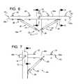
- FIG. 8is a section view of the crossarm systems of FIGS. 6 and 7 depicting insulator pin assemblies supported by these crossarm systems;
- FIG. 9is a section view taken along lines 9 — 9 in FIGS. 6 and 7 ;
- FIG. 10is a section view taken along lines 10 — 10 in FIG. 6 .
- FIGS. 6 and 7are two exemplary crossarm systems constructed in accordance with, and embodying, the principles of the present invention.
- FIG. 6illustrates first embodiment of a crossarm system 10 a
- FIG. 7illustrates a second embodiment of a crossarm system 10 b.
- the crossarm systems 10are adapted to be attached to a pole 12 .
- a crossarm bolt assembly 14 extending through a crossarm bore 16 in the pole 12forms the main point of attachment between the crossarm system and the pole 12 ( FIG. 9 ).
- the crossarm systems 10are typically additionally braced by one or more brace assemblies 20 extending between the crossarm systems 10 and the pole 12 .
- Each of the crossarm systems 10supports a plurality of insulator pin assemblies 22 that are in turn used to support power lines (not shown).
- the crossarm bolt assembly 12 , brace assemblies 20 , and insulator pin assemblies 22are or may be conventional. Examples of these assemblies 12 , 20 , and 22 will be described herein to provide a full understanding of the benefits yielded by the present invention; however, the details of these assemblies 12 , 20 , and 22 are not important to any given implementation of the present invention, and other assemblies with similar structural characteristics may be used instead.
- the brace assemblies 20may be omitted in a braceless crossarm system.
- the first exemplary crossarm system 10 aemploys two brace assemblies 20 and the second exemplary crossarm system employs a single brace assembly 20 .
- the brace assemblies 20each comprise a brace member 24 , an upper bracket assembly 26 , and a lower bracket assembly 28 .
- the bracket assembliescan take different forms, and only the upper bracket assemblies 26 of the first crossarm system 10 a will be described in detail herein.
- the upper bracket assembly 26 of the crossarm system 10 acomprises a bracket member 30 , a bracket bolt 32 , a bracket nut 34 , and a bracket washer 36 .
- the first crossarm system 10 aemploys four insulator pin assemblies 22
- the second crossarm system 10 bemploys two insulator pin assemblies 22 .
- More or fewer insulator pin assemblies 22may be used in a given circumstance, but the principles of the present invention should be clear with reference to the crossarm systems 10 a and 10 b .
- Each of the exemplary insulator pin assemblies 22comprises an insulator pin 40 , an insulator pin nut 42 , and a pair of insulator washers 44 , but other configurations of insulator pin assemblies may be used in place of the insulator pin assemblies shown.
- the crossarm bolt assembly 50 of both of the crossarm systems 10 a and 10 bcomprises a crossarm bolt 50 , a crossarm nut 52 , a crossarm plate 54 , and an anchor plate 56 .
- Other configurations of crossarm bolt assembliesmay be used.
- the crossarm system 10 of the present inventioncomprises a crossarm member 60 and a pair of nail end plates 62 .
- FIG. 6depicts a first embodiment of a crossarm system 10 a comprising a crossarm member 60 a
- FIG. 7depicts a second embodiment of a crossarm system 10 b comprising a crossarm member 60 b
- the crossarm members 60 a and 60 bare treated wooden members defining an upper surface 70 , a lower surface 72 , an inside surface 74 , an outside surface 76 , a first end surface 80 , and a second end surface 82 (see FIG. 9 ).
- the crossarm members 60 a and 60 b used by the crossarm systems 10 a and 10 bmay be identical or may be engineered to have different lengths or cross-sectional areas.
- the exemplary crossarm members 60 a and 60 bhave the same cross-sectional area but differ in length.
- the terms “vertical” and “horizontal”refer to directions relative to the crossarm member 60 when mounted to a pole 12 under normal conditions. Implicit in these definitions is the term “substantially”; in particular, during normal use the end surfaces 80 and 82 can be within ten degrees of vertical, and the upper and lower surfaces 70 and 72 can be within ten degrees of horizontal.
- a number of boresare formed in the crossarm member 60 .
- a horizontal main bore 90extends between the inside and outside surfaces 74 and 76 .
- the crossarm bolt 50extends through the main bore 90 as shown in FIG. 9 .
- a plurality of vertical pin bores 92extend between the upper and lower surfaces 70 and 72 .
- the insulator pins 40extend through the pin bores 92 .
- a brace bore 94is formed for each upper bracket assembly 26 .
- the brace bores 94may be horizontal or vertical depending upon the details of the bracket member 30 .
- FIG. 10depicts the vertical brace bore 94 formed in the example crossarm member 60 a depicted in FIG. 6 .
- the bracket bolts 32extend through the brace bores 94 .
- Structural failure of wooden members made from a solid piece of wood, such as the crossarm member 60is often caused by splitting of the wooden member along the grain. Splits in a wooden member tend to begin as small cracks in the end surfaces 80 and/or 82 that progressively increase in size as the wood endures wet and dry cycles and/or the wood is subjected to external loads.
- Splittingcan result in catastrophic structural failure of the wooden member. Splitting of the wood also facilitates deterioration of wood by exposing the untreated interior of the wooden member to the elements.
- the bores 90 , 92 , and 94make the crossarm member 60 especially susceptible to splitting and the problems associated therewith.
- the borescreate weak points in the crossarm member 60 by damaging the wood fibers and reducing the cross-sectional area of the wooden member.
- the bores 90 , 92 , and 94receive bolts that transfer external loads to the wooden member; these loads introduce stresses into the crossarm member 60 at the points where the member 60 is the weakest.
- the bores pin bores 92are most problematic because, as shown in FIG. 8 , one of the pin bores 92 is typically the bore formed in the crossarm member 60 closest to the end surfaces 80 and 82 .
- the nail end plates 62are secured to the crossarm member end surfaces 80 and 82 to reduce splitting of the crossarm member 60 .
- the nail end plates 62comprise a plate member 110 and a plurality of nail projections 112 .
- the nail projections 112are driven into the crossarm member end surfaces 80 and 82 , and the plate member 110 forms a structural base that maintains the nail projections 112 in a predetermined relationship with each other.
- the nail projections 112engage spaced apart portions of the crossarm member 60 in a manner that prevents these portions from moving relative to each other.
- the nail end plates 62thus mechanically engage the crossarm member 60 to prevent small cracks from developing into splits that could result in failure of the crossarm member 60 .
- the nail end plates 62define plate openings 114 that are associated with each of the nail projections 112 .
- the nail end plates 62are preferably formed from a flat blank that is stamped with a die (not shown) to obtain the nail projections 112 .
- the blank, and the nail end plates 62 formed therefrom,are preferably made of a rigid material such as steel. Other materials with similar structural characteristics may also be used. If steel is used, the nail end plate 62 may be made of galvanized steel or stainless steel or may be coated to resist corrosion.
- the stamping processsimultaneously cuts and bends material from the blank, forming the nail projections 112 out of the material removed from the blank and, as a byproduct, forming the plate openings 114 .
- the die used to form the nail end plates 62determines the sizes, shapes, and locations of the nail projections 112 .
- the stamping processis conventional and will not be described herein in further detail.
- the dieis made in a conventional manner, and this discussion of the nail end plates 62 will instruct one of ordinary skill in the art how to make use an appropriate die.
- nail end plates 62are preferably die-stamped, other methods of forming the nail end plates 62 , such as casting, molding, milling, or the like may be used.
- the plate member 110defines a plate inner surface 120 , a plate outer surface 122 , and first, second, third, and fourth plate edges 130 , 132 , 134 , and 136 .
- the plate member 110is substantially rectangular, but other shapes may be used.
- a thickness of the plate member 110is defined as the distance between the plate inner and outer surfaces 120 and 122 .
- a height of the plate member 110is defined as a length of the first and second edges 130 and 132 , while a width of the plate member 110 is defined as a length of the third and fourth edges 134 and 136 .
- the nail projections 112extend at substantially a right angle from the inner surface 120 of the plate member 112 .
- the nail projections 112define a tip portion 140 and a shaft portion 142 .
- the tip portion 140is generally triangular in shape, while the shaft portion 142 is generally rectangular in shape.
- the nail projections 112further define first and second side portions 144 and 146 that extend from a ridge portion 148 .
- the side portions 144 and 146are flat and extend from each other at an interior angle of less than 180°.
- the surfaces of the nail projectionsare identified in FIG.
- a tip of the nail projections 112is identified by reference character 154
- a base of the nail projections 112is identified by reference character 156 .
- the plate openings 114will now be described in further detail with respect to FIG. 3 .
- the plate openings 114are primarily a byproduct of a cost-effective and preferred method of forming the nail end plates 62 .
- the plate openings 114will be described in further detail herein to define further the relative arrangements and groupings of the nail projections 112 .
- the plate openings 114each define a projection axis 162 that is parallel to a length dimension 162 and perpendicular to a width dimension 164 of the plate openings 114 .
- the plate openings 114further define a base end 166 adjacent to the nail projection 112 associated therewith and a tip end 168 distal from the base end 166 .
- the face surface 150 of the nail projections 112is arranged towards the plate opening 114 associated therewith.
- the face surfaces 150 and back surfaces 152define a width dimension of the projections 114 (perpendicular to the projection axis 162 ).
- the dimensions of the side portions 146 and 148 and interior angle between these portions 146 and 148define a depth dimension of the projections 114 (parallel to the projection axis 162 ).
- the width dimensionis larger than the depth dimension, so each individual nail projection 114 exposes a greater surface area to the wood in the width dimension than in the depth dimension.
- the width dimensionpresents greater resistance to relative movement between the wood and the nail projection.
- the projection axes 162thus correspond to the orientation of the nail projection 112 that provides the greatest resistance to movement of the wood relative to the nail projection.
- the nail projectionsare arranged in discrete arrays. These arrays will be referred to as a first array 170 , a second array 172 , a third array 174 , and a fourth array 176 .
- a gap region 178is defined. The gap region 178 does not contain any nail projections and is substantially surrounded by the arrays 170 – 176 .
- the projection axes 162 of the nail projections 112 within each of the arrays 170 – 176are aligned with each other.
- the arrays themselvesare thus directional in that the nail projections 112 within the arrays are grouped to accumulate the increased resistance to wood movement provided by the face and back surfaces 150 and 152 .
- FIG. 2thus shows that the projection axes of the first and second arrays 170 and 172 are aligned with each other, the projection axes of the third and fourth arrays 174 and 176 are aligned with each other, and the projection axes of the first and second arrays 170 and 172 are perpendicular to the projection axes of the third and fourth arrays 174 and 176 .
- FIG. 2also shows that the nail end plates 62 are attached to the end surfaces 80 , 82 of the crossarm member 60 .
- This attachmentis formed by displacing the nail end plates 62 towards the end surfaces 80 and 82 of the crossarm member 60 such that the nail projections 112 enter the wood at these end surfaces 80 , 82 .
- the nail end plates 62are displaced until the plate inner surface 120 comes into contact with the end surfaces 80 , 82 .
- the first plate edge 130is adjacent to the crossarm upper surface 70
- the second plate edge 132is adjacent to the crossarm lower surface 72
- the third plate edge 134is adjacent to the crossarm outside surface 76
- the fourth plate edge 136is adjacent to the crossarm inside surface 74 .
- the attachment of the nail end plates 62 to the crossarm member 60provides resistance to movement of wood relative to the plate member 110 in both of two orthogonal directions relative to the plate member 110 .
- the width dimensions of the nail projections 112inhibit splitting of the wood along the projection axes as defined above.
- the interior angle between the first and second side portions 142 and 144 of the nail projectionsinhibit splitting of the wood in directions at an angle to the projection axes.
- the nail end plates 62thus mechanically engage the crossarm member 60 to inhibit splitting in most if not all radial directions from the center of the crossarm member 60 .
- Shown at 180 in FIG. 3is a first spacing distance between each of the nail projections and the closest plate opening with a collinear hole axis.
- Reference character 182identifies a second spacing distance between adjacent nail projections with parallel projection axes.
- Reference character 184identifies a minimum spacing distance between nail projections in one array and the closest nail projection in an adjacent array. The minimum spacing distance may vary between different arrays.
- the hole projectionsare arranged such that the nail projections are close enough to each other to stabilize the wood to prevent splitting but not so close that the nail projections themselves do not encourage splitting.
- rowsare defined as nail projections/plate openings with collinear projection axes (rows can contain a single nail projection/plate opening).
- the nail projectionsare arranged with the face surfaces of one nail projection facing the back surface of the adjacent nail projection in that row.
- the nail projections and tip ends of the plate openingsare alternated such that nail projections are offset from one another in the adjacent rows. This pattern spaces out the nail projections such that, within a given array, the nail projections do not enter the wood at closely spaced locations and encourage splitting.
- the minimum spacing distance between nail projections in adjacent arraysshould be kept as large as possible; when, as between the arrays 170 and 176 , the minimum spacing distance between adjacent nail projections is relatively small, the nail projections are oriented such that projection axes are perpendicular to each other. Again, the offset projection axes result in offset penetration into the wood that is less likely to encourage splitting.
- FIG. 5depicted at 62 b therein is a second exemplary nail end plate constructed in accordance with, and embodying, the principles of the present invention.
- the nail end plate 62 bis similar in most respects to the nail end plate 62 described above and will only be described herein to the extent that the two nail end plates differ.
- the nail end plate 62 bcomprises four arrays 170 , 172 , 174 , and 176 of nail projections, but the number of nail projections in each of these arrays is different for the nail end plate 62 b .
- the first and second arrays 170 and 172 of the nail end plate 62 beach contains six nail projections, while the third and fourth arrays 174 and 176 each contain twenty-six nail projections.
- nail projections and arraysare possible.
- arrays shown in the exemplary nail end plates 62 and 62 bare rectangular, other shapes are possible.
- Table Aidentifies a number of parameters defined above with reference to the nail end plates 62 of the present invention and sets forth preferred numerical values and first and second preferred numerical ranges for each of these parameters:
- nail end plates 62are preferred and is particularly suited to use with conventional crossarms, other nail end plates can be constructed that fall within the scope of the present invention.
- the scope of the present inventionshould thus be determined with reference to the following claims and not the preferred embodiments described above.
Landscapes
- Engineering & Computer Science (AREA)
- Architecture (AREA)
- Life Sciences & Earth Sciences (AREA)
- Wood Science & Technology (AREA)
- Civil Engineering (AREA)
- Structural Engineering (AREA)
- Joining Of Building Structures In Genera (AREA)
Abstract
Description
The present invention relates to crossarm systems and, more particularly, to wood crossarms adapted to suspend power lines from power poles.
A crossarm is a rigid member that is secured to a vertical pole for the purpose of supporting one or more power lines above the ground. Typically, the vertical pole is a wooden pole. The crossarm can be made of many materials, but crossarms made of treated wood have the requisite structural characteristics, are relatively inexpensive, and can last up to 50 years or more when properly installed and maintained. The present invention relates to wood crossarms.
A first portion of a crossarm is typically secured to a first location on the pole by a crossarm bolt that extends through the pole and the crossarm. Many crossarms are also supported at a second portion, and often a third portion, by one or more brace assemblies. The brace assemblies extend between the pole at a second location below the first location and the second and/or third portions of the crossarm. Whether or not brace assemblies are used, the resulting structure is engineered to allow the loads of power lines and the like to be suspended from the crossarm.
As generally discussed above, treated wood has desirable cost and structural properties and, overall, is preferred for use as a crossarm. The term “treated wood” as used herein refers to a wooden member that has been treated with a preservative material. The preservative material typically includes pesticides such as insecticides, fungicides, and the like that discourage the growth of biological organisms that would otherwise degrade the structural properties of wood over time. Typically, the preservative material uses oil or water as a vehicle for carrying the pesticides into the wooden member.
In particular, a wooden member is milled into the desired shape of a crossarm. The surface of the wooden member is then incised to allow for improved penetration of the preservative into the wood. The wooden member is then immersed in the preservative material in a pressure tank. The tank is pressurized to force the preservative material into the wooden member to obtain the treated wood crossarm. Depending on the specie of wood, the preservative material may or may not penetrate completely through the wooden member; the preservative material may only extend into a boundary region that is protected by the preservative material, leaving an interior region that is unprotected by pesticides.
One cause of the premature failure of wooden crossarm members relates to splitting of the ends of the wooden member. In wood crossarms that are not totally penetrated by pesticides, such splitting allows the untreated interior region of the wooden member to be exposed to biological organisms that cause it to degrade. Splitting also adversely affects the ability of a wooden crossarm to bear the loads placed thereon by power lines and the like. In either case, splitting of the crossarm member can result in failure of the crossarm system.
The need thus exists for crossarm systems and methods that are less susceptible to splitting and the system failures associated therewith.
The Applicant is aware of the use of nail end plates with railroad ties, and an example of a nail end plate adapted for use with a railroad tie is depicted inFIG. 1 of the present invention.
U.S. Pat. Nos. 5,116,179 to Matlock and 5,551,819 to Stern disclose nail end plates for use in railroad ties; the Stern patent specifically discusses railroad ties and generally indicates that this nail end plate could be used on other wood products but does not specifically mention any other types of products.
The nail end plate of the Stern patent employs a field of intermediate teeth formed in a conventional manner and edge teeth formed along at least two and preferably four opposing edges of the nail end plate. The edge teeth are formed such that the wide surfaces defined thereby oppose each other when they penetrate the wood. Before the teeth are punched or forced from the plate, the edge teeth extend completely outwardly from the plate.
The Stern patent further discloses as prior art the use of an “S-iron” and a “C-iron” that are driven into the end of a railroad tie to reduce splitting thereof.
The nail end plate described in the Matlock patent employs teeth or nail portions that are arranged in adjacent laterally-spaced rows, with alternating teeth in each row being laterally offset from adjacent teeth within the row. The teeth are also defined as having a shank portion and a tip portion, with the shank portion being V-shaped in cross-section.
U.S. Pat. No. 2,273,507 to Beegle also relates to a device for reducing the splitting of railroad ties, but this device is not a nail end plate as described in the Matlock and Stern patents. The Beegle patent discloses an anti-splitting device similar the “S-iron” and C'iron” devices of the Stern patent, but the Beegle device employs a generally U-shaped cross-section.
The Applicant is also aware of the use of nail plates to join two pieces of wood together. As examples, U.S. Pat. Nos. 3,910,153 to Jureit and 3,892,160 to Jureit et al. disclose nail plates engineered for forming joints between the wooden members used to form a truss.
The present invention may be embodied as a crossarm system adapted to support power lines from a vertical pole or a method of making such a crossarm system. The crossarm system comprises a wooden crossarm member and first and second nail end plates. The wooden crossarm member defines upper, lower, inner, and outer surfaces and first and second end surfaces, a main bore, a plurality of pin bores, and at least one brace bore. Each nail end plate comprises a plate member defining an inner surface and an outer surface and a plurality of nail projections extending from the inner surface of the plate member. Each nail projection defines a width dimension. In use, the first and second nail end plates are displaced towards the first and second end surfaces, respectively, such that the nail projections enter the wooden crossarm member. The nail projections are arranged such that the width dimensions substantially prevent splitting of the ends of the crossarm member.
Referring now to the drawing, identified byreference character 10 inFIGS. 6 and 7 are two exemplary crossarm systems constructed in accordance with, and embodying, the principles of the present invention.FIG. 6 illustrates first embodiment of acrossarm system 10a, whileFIG. 7 illustrates a second embodiment of acrossarm system 10b.
Thecrossarm systems 10 are adapted to be attached to apole 12. Acrossarm bolt assembly 14 extending through acrossarm bore 16 in thepole 12 forms the main point of attachment between the crossarm system and the pole12 (FIG. 9 ). Thecrossarm systems 10 are typically additionally braced by one ormore brace assemblies 20 extending between thecrossarm systems 10 and thepole 12. Each of thecrossarm systems 10 supports a plurality ofinsulator pin assemblies 22 that are in turn used to support power lines (not shown).
Thecrossarm bolt assembly 12,brace assemblies 20, andinsulator pin assemblies 22 are or may be conventional. Examples of theseassemblies assemblies brace assemblies 20 may be omitted in a braceless crossarm system.
Referring initially to thebrace assemblies 20, the firstexemplary crossarm system 10aemploys twobrace assemblies 20 and the second exemplary crossarm system employs asingle brace assembly 20. Thebrace assemblies 20 each comprise abrace member 24, anupper bracket assembly 26, and alower bracket assembly 28. The bracket assemblies can take different forms, and only theupper bracket assemblies 26 of thefirst crossarm system 10awill be described in detail herein. As shown inFIG. 10 , theupper bracket assembly 26 of thecrossarm system 10acomprises a bracket member30, abracket bolt 32, abracket nut 34, and abracket washer 36.
Thefirst crossarm system 10aemploys fourinsulator pin assemblies 22, while thesecond crossarm system 10bemploys twoinsulator pin assemblies 22. More or fewerinsulator pin assemblies 22 may be used in a given circumstance, but the principles of the present invention should be clear with reference to thecrossarm systems insulator pin assemblies 22 comprises aninsulator pin 40, aninsulator pin nut 42, and a pair ofinsulator washers 44, but other configurations of insulator pin assemblies may be used in place of the insulator pin assemblies shown.
Thecrossarm bolt assembly 50 of both of thecrossarm systems crossarm bolt 50, acrossarm nut 52, acrossarm plate 54, and ananchor plate 56. Other configurations of crossarm bolt assemblies may be used.
As shown inFIGS. 6 and 7 , thecrossarm system 10 of the present invention comprises acrossarm member 60 and a pair ofnail end plates 62. In particular,FIG. 6 depicts a first embodiment of acrossarm system 10acomprising acrossarm member 60a, whileFIG. 7 depicts a second embodiment of acrossarm system 10bcomprising acrossarm member 60b. Thecrossarm members upper surface 70, alower surface 72, aninside surface 74, anoutside surface 76, afirst end surface 80, and a second end surface82 (seeFIG. 9 ). Thecrossarm members crossarm systems exemplary crossarm members
In the following discussion, the terms “vertical” and “horizontal” refer to directions relative to thecrossarm member 60 when mounted to apole 12 under normal conditions. Implicit in these definitions is the term “substantially”; in particular, during normal use the end surfaces80 and82 can be within ten degrees of vertical, and the upper andlower surfaces
To accommodate thecrossarm bolt assembly 14,insulator pin assemblies 22, andupper bracket assemblies 26, a number of bores are formed in thecrossarm member 60. In particular, a horizontalmain bore 90 extends between the inside and outside surfaces74 and76. Thecrossarm bolt 50 extends through themain bore 90 as shown inFIG. 9 . A plurality of vertical pin bores92 extend between the upper andlower surfaces upper bracket assembly 26. The brace bores94 may be horizontal or vertical depending upon the details of the bracket member30.FIG. 10 depicts the vertical brace bore94 formed in theexample crossarm member 60adepicted inFIG. 6 . Thebracket bolts 32 extend through the brace bores94.
Structural failure of wooden members made from a solid piece of wood, such as thecrossarm member 60, is often caused by splitting of the wooden member along the grain. Splits in a wooden member tend to begin as small cracks in the end surfaces80 and/or82 that progressively increase in size as the wood endures wet and dry cycles and/or the wood is subjected to external loads.
Splitting can result in catastrophic structural failure of the wooden member. Splitting of the wood also facilitates deterioration of wood by exposing the untreated interior of the wooden member to the elements.
Thebores crossarm member 60 especially susceptible to splitting and the problems associated therewith. In particular, the bores create weak points in thecrossarm member 60 by damaging the wood fibers and reducing the cross-sectional area of the wooden member. In addition, thebores crossarm member 60 at the points where themember 60 is the weakest. The bores pin bores92 are most problematic because, as shown inFIG. 8 , one of the pin bores92 is typically the bore formed in thecrossarm member 60 closest to the end surfaces80 and82.
Thenail end plates 62 are secured to the crossarm member end surfaces80 and82 to reduce splitting of the crossarmmember 60. As shown inFIGS. 3 and 4 , thenail end plates 62 comprise aplate member 110 and a plurality of nail projections112. In use, the nail projections112 are driven into the crossarm member end surfaces80 and82, and theplate member 110 forms a structural base that maintains the nail projections112 in a predetermined relationship with each other. The nail projections112 engage spaced apart portions of the crossarmmember 60 in a manner that prevents these portions from moving relative to each other. Thenail end plates 62 thus mechanically engage thecrossarm member 60 to prevent small cracks from developing into splits that could result in failure of the crossarmmember 60.
The structure of the preferrednail end plates 62 will now be described in further detail with reference toFIGS. 3 and 4 . Thenail end plates 62 define plate openings114 that are associated with each of the nail projections112. Thenail end plates 62 are preferably formed from a flat blank that is stamped with a die (not shown) to obtain the nail projections112. The blank, and thenail end plates 62 formed therefrom, are preferably made of a rigid material such as steel. Other materials with similar structural characteristics may also be used. If steel is used, thenail end plate 62 may be made of galvanized steel or stainless steel or may be coated to resist corrosion.
The stamping process simultaneously cuts and bends material from the blank, forming the nail projections112 out of the material removed from the blank and, as a byproduct, forming the plate openings114. The die used to form thenail end plates 62 determines the sizes, shapes, and locations of the nail projections112. The stamping process is conventional and will not be described herein in further detail. The die is made in a conventional manner, and this discussion of thenail end plates 62 will instruct one of ordinary skill in the art how to make use an appropriate die.
Although thenail end plates 62 are preferably die-stamped, other methods of forming thenail end plates 62, such as casting, molding, milling, or the like may be used.
Theplate member 110 defines a plateinner surface 120, a plateouter surface 122, and first, second, third, and fourth plate edges130,132,134, and136. Theplate member 110 is substantially rectangular, but other shapes may be used. A thickness of theplate member 110 is defined as the distance between the plate inner andouter surfaces plate member 110 is defined as a length of the first andsecond edges plate member 110 is defined as a length of the third andfourth edges
The nail projections112 extend at substantially a right angle from theinner surface 120 of the plate member112. When viewed from the side as shown inFIG. 4 , the nail projections112 define atip portion 140 and ashaft portion 142. Thetip portion 140 is generally triangular in shape, while theshaft portion 142 is generally rectangular in shape. When viewed from the end as perhaps best shown inFIG. 3 , the nail projections112 further define first andsecond side portions ridge portion 148. Theside portions FIG. 3 as aface surface 150 arranged towards the plate opening114 associated therewith and aback surface 152. Theface surface 150 is arranged towards the interior angle between theside portions reference character 154, and a base of the nail projections112 is identified by reference character156.
The plate openings114 will now be described in further detail with respect toFIG. 3 . As generally discussed above, the plate openings114 are primarily a byproduct of a cost-effective and preferred method of forming thenail end plates 62. However, the plate openings114 will be described in further detail herein to define further the relative arrangements and groupings of the nail projections112.
In particular, the plate openings114 each define aprojection axis 162 that is parallel to alength dimension 162 and perpendicular to awidth dimension 164 of the plate openings114. The plate openings114 further define abase end 166 adjacent to the nail projection112 associated therewith and atip end 168 distal from thebase end 166.
Theface surface 150 of the nail projections112 is arranged towards the plate opening114 associated therewith. The face surfaces150 andback surfaces 152 define a width dimension of the projections114 (perpendicular to the projection axis162). The dimensions of theside portions portions
Referring now toFIG. 2 , as shown therein the nail projections are arranged in discrete arrays. These arrays will be referred to as afirst array 170, asecond array 172, athird array 174, and afourth array 176. In the exemplarynail end plates 62, agap region 178 is defined. Thegap region 178 does not contain any nail projections and is substantially surrounded by thearrays 170–176.
The projection axes162 of the nail projections112 within each of thearrays 170–176 are aligned with each other. The arrays themselves are thus directional in that the nail projections112 within the arrays are grouped to accumulate the increased resistance to wood movement provided by the face and back surfaces150 and152.
With thenail end plates 62 so attached to thecrossarm member 60, thefirst plate edge 130 is adjacent to the crossarmupper surface 70, thesecond plate edge 132 is adjacent to the crossarmlower surface 72, thethird plate edge 134 is adjacent to the crossarm outsidesurface 76, and thefourth plate edge 136 is adjacent to the crossarm insidesurface 74.
The attachment of thenail end plates 62 to thecrossarm member 60 provides resistance to movement of wood relative to theplate member 110 in both of two orthogonal directions relative to theplate member 110. The width dimensions of the nail projections112 inhibit splitting of the wood along the projection axes as defined above. Additionally, the interior angle between the first andsecond side portions nail end plates 62 thus mechanically engage thecrossarm member 60 to inhibit splitting in most if not all radial directions from the center of the crossarmmember 60.
Referring for a moment back toFIG. 3 , depicted therein are a number of other factors that may be considered when designing nail end plate according to the principles of the present invention. Shown at180 inFIG. 3 is a first spacing distance between each of the nail projections and the closest plate opening with a collinear hole axis.Reference character 182 identifies a second spacing distance between adjacent nail projections with parallel projection axes.Reference character 184 identifies a minimum spacing distance between nail projections in one array and the closest nail projection in an adjacent array. The minimum spacing distance may vary between different arrays.
In general, the hole projections are arranged such that the nail projections are close enough to each other to stabilize the wood to prevent splitting but not so close that the nail projections themselves do not encourage splitting.
In addition, within a given array rows are defined as nail projections/plate openings with collinear projection axes (rows can contain a single nail projection/plate opening). Within each row having more than one nail projection/plate opening, the nail projections are arranged with the face surfaces of one nail projection facing the back surface of the adjacent nail projection in that row. For two adjacent rows in a given array, the nail projections and tip ends of the plate openings are alternated such that nail projections are offset from one another in the adjacent rows. This pattern spaces out the nail projections such that, within a given array, the nail projections do not enter the wood at closely spaced locations and encourage splitting.
The minimum spacing distance between nail projections in adjacent arrays should be kept as large as possible; when, as between thearrays
Referring now toFIG. 5 , depicted at62btherein is a second exemplary nail end plate constructed in accordance with, and embodying, the principles of the present invention. Thenail end plate 62bis similar in most respects to thenail end plate 62 described above and will only be described herein to the extent that the two nail end plates differ.
Like thenail end plate 62, thenail end plate 62bcomprises fourarrays nail end plate 62b. In particular, the first andsecond arrays nail end plate 62beach contains six nail projections, while the third andfourth arrays
Other configurations of nail projections and arrays are possible. In particular, while the arrays shown in the exemplarynail end plates
The following Table A identifies a number of parameters defined above with reference to thenail end plates 62 of the present invention and sets forth preferred numerical values and first and second preferred numerical ranges for each of these parameters:
| TABLE A | |||
| SECOND | |||
| FIRST | FIRST | PRE- | |
| PREFERRED | PREFERRED | FERRED | |
| PARAMETER | EMBODIMENT | RANGE | RANGE |
| Nail projection height | 0.5″ | 0.4″–0.6″ | 0.3″–0.75″ |
| nail projection width | 0.15″ | 0.13″–0.17″ | 0.1″–0.25″ |
| first spacing distance | 0.15″ | 0.13″–0.17″ | 0.1″–0.3″ |
| second spacing dis- | 0.19″ | 0.15″–0.24″ | 0.1″–0.3″ |
| tance | |||
| plate member | 18 | 20 gauge– | 22 gauge– |
| gauge/ | 16 | 14 gauge | |
| total number of | 62 | 38–70 | 12–88 |
| projections | |||
| number of nail | 18 | 6–18 | 3–18 |
| projections in first and | |||
| second arrays | |||
| number of nail | 13 | 13–17 | 3–26 |
| projections in third and | |||
| fourth arrays | |||
| plate member height | 3.5″ | 3″–4″ | 2.25″–5″ |
| plate member width | 4.5″ | 4″–5″ | 4″–9″ |
Given the foregoing, it should be clear that, while thenail end plates 62 are preferred and is particularly suited to use with conventional crossarms, other nail end plates can be constructed that fall within the scope of the present invention. The scope of the present invention should thus be determined with reference to the following claims and not the preferred embodiments described above.
Claims (5)
1. A method of supporting power lines from a vertical pole, the method comprising the steps of:
providing a wooden crossarm member defining upper, lower, inner, and outer surfaces and first and second end surfaces;
providing a crossarm bolt assembly;
providing a plurality of insulator pin assemblies, where each insulator pin assembly is adapted to support one of the power lines;
providing at least one brace assembly comprising an upper bracket assembly a lower bracket assembly adapted to be attached to the vertical pole;
forming a main bore in the crossarm member, where the main bore extends between inner and outer surface and is adapted to receive a crossarm bolt;
forming a plurality of pin bores in the crossarm member, where the pin bores extend between the upper and lower surfaces and are adapted to receive an insulator pin;
forming at least one brace bore in the crossarm member;
providing first and second nail end plates comprising plate member defining an inner surface and an outer surface;
forming a plurality of nail projections on the plate member such that the nail projections extend from the inner surface of the plate member, and
each nail projection defines a width dimension;
displacing the first and second nail end plates towards the first and second end surfaces, respectively, such that the nail projections enter the wooden crossarm member;
extending the crossarm bolt assembly through the main bore to secure the wooden crossarm member to the vertical pole;
extending each insulator pin assembly through one of the pin bores formed in the wooden crossarm member;
securing the upper bracket assembly to the at least one brace bore; wherein
the nail projections are arranged such that the width dimensions substantially prevent splitting of the crossarm member caused by loads applied to pin bores of the crossarm member by the power lines through the insulator pin assemblies.
2. A method as recited inclaim 1 , further comprising the step of arranging the nail projections in a plurality of arrays such that projection axes of the nail projections in each array are parallel with each other.
3. A method as recited inclaim 1 , further comprising the step of forming the arrays of nail projections such that the projection axes of the nail projections in one of the arrays are perpendicular to the projection axes of the nail projections in another of the arrays.
4. A method as recited inclaim 3 , further comprising the step of arranging the nail projections in first, second, third, and fourth arrays such that
the projection axes of the nail projections in the first and second arrays are parallel to each other;
the projection axes of the nail projections in the third and fourth arrays are parallel to each other;
the first and second arrays are arranged on opposite sides of a gap region where no nail projections are formed; and
the second and third arrays are arranged on opposite sides of the gap region.
5. A method as recited inclaim 1 , in which step of forming the nail projections comprises the step of die-stamping the nail projections.
Priority Applications (1)
| Application Number | Priority Date | Filing Date | Title |
|---|---|---|---|
| US10/254,412US7007438B1 (en) | 2002-09-24 | 2002-09-24 | Crossarm systems and methods |
Applications Claiming Priority (1)
| Application Number | Priority Date | Filing Date | Title |
|---|---|---|---|
| US10/254,412US7007438B1 (en) | 2002-09-24 | 2002-09-24 | Crossarm systems and methods |
Publications (1)
| Publication Number | Publication Date |
|---|---|
| US7007438B1true US7007438B1 (en) | 2006-03-07 |
Family
ID=35966066
Family Applications (1)
| Application Number | Title | Priority Date | Filing Date |
|---|---|---|---|
| US10/254,412Expired - Fee RelatedUS7007438B1 (en) | 2002-09-24 | 2002-09-24 | Crossarm systems and methods |
Country Status (1)
| Country | Link |
|---|---|
| US (1) | US7007438B1 (en) |
Cited By (11)
| Publication number | Priority date | Publication date | Assignee | Title |
|---|---|---|---|---|
| US20050247015A1 (en)* | 2004-05-07 | 2005-11-10 | Gary Baumgartner | Method and apparatus for replacing a utility pole |
| US20080271386A1 (en)* | 2004-11-26 | 2008-11-06 | Holland Railconsult B.V. | High-Tension Tower, Power Transporting System, Power Transporting Method and Assembling Method |
| US20100192373A1 (en)* | 2009-01-30 | 2010-08-05 | Consolidated Edison Company Of New York, Inc. | Device for installing aerial electrical power lines and method of operation |
| GB2477288A (en)* | 2010-01-27 | 2011-08-03 | Illinois Tool Works | Reinforcement plate for weakened joist |
| US20120205502A1 (en)* | 2011-02-11 | 2012-08-16 | Oliphant Wesley J | Support apparatus for supporting utility cables and utility transmission line including same |
| EP2532809A3 (en)* | 2011-06-08 | 2014-09-17 | INDUO Gesellschaft zur Verwertung von Schutzrechten mbH & Co. KG | Cross arm assembly, in particular for overhead line masts |
| US20160336727A1 (en)* | 2014-01-08 | 2016-11-17 | K-Line Insulators Limited | Insulated power line framings |
| US20170063068A1 (en)* | 2015-08-27 | 2017-03-02 | Austin Cary Bennett | Resilient cross arm assembly |
| US10019500B2 (en) | 2005-02-28 | 2018-07-10 | Huawei Technologies Co., Ltd. | Method for sharing and searching playlists |
| US10865558B2 (en) | 2015-12-31 | 2020-12-15 | Simpson Strong-Tie Company, Inc. | Adjustable tension tie |
| US20210111548A1 (en)* | 2019-10-14 | 2021-04-15 | Slingco Limited | Utility line support structure |
Citations (35)
| Publication number | Priority date | Publication date | Assignee | Title |
|---|---|---|---|---|
| US839272A (en)* | 1906-09-24 | 1906-12-25 | Anderson G Crow | Cement pole. |
| US1815598A (en)* | 1929-04-19 | 1931-07-21 | Charles L Stroup | Insulating member for high tension construction |
| US2273507A (en) | 1940-06-14 | 1942-02-17 | Raymond E Beegle | Antisplitting device |
| US3241424A (en) | 1963-12-05 | 1966-03-22 | Hydro Air Eng Inc | Connector plates with rigid tooth structure |
| US3509678A (en)* | 1968-12-10 | 1970-05-05 | Joslyn Mfg & Supply Co | Apparatus for supporting electrical components and method of making the same |
| US3555747A (en)* | 1969-06-12 | 1971-01-19 | Mif Ind Inc | Lightweight crossarm assemblies |
| US3603717A (en)* | 1970-01-07 | 1971-09-07 | Cp Corp | Crossarm assembly |
| US3649740A (en)* | 1967-11-09 | 1972-03-14 | John R Boyer | Pole-top structure for electric distribution lines |
| US3653622A (en)* | 1970-04-20 | 1972-04-04 | Aluma Form Inc | Nonlineal crossarm for bracketing electrical devices |
| US3884442A (en)* | 1974-09-30 | 1975-05-20 | Hopeman Brothers Inc | Two post insulator support for utility poles |
| US3892160A (en)* | 1974-04-19 | 1975-07-01 | John Calvin Jureit | Connector plate |
| US3910153A (en)* | 1971-06-15 | 1975-10-07 | Automated Building Components | Wood joint and connector plates |
| US3911548A (en)* | 1974-10-02 | 1975-10-14 | Interpace Corp | Method for replacing existing utility pole without disturbing hardware mounted thereon |
| US4127739A (en)* | 1977-02-10 | 1978-11-28 | Aluma-Form Inc. | Level mount electrical component bracket |
| US4194080A (en)* | 1978-04-17 | 1980-03-18 | Bruce-Lake Company | Utility line support structure |
| US4262047A (en)* | 1979-10-30 | 1981-04-14 | Barnett George D | Fiberglass utility pole crossarm |
| US4418509A (en)* | 1979-08-30 | 1983-12-06 | Gang-Nail Systems, Inc. | Structural joint connector |
| US4615154A (en)* | 1985-06-28 | 1986-10-07 | Trus Joist Corporation | Utility line transmission tower apparatus |
| US4654540A (en)* | 1985-10-07 | 1987-03-31 | Bridges Ronald P | Group operated circuit disconnect apparatus for overhead electric power lines |
| US4682747A (en)* | 1986-04-24 | 1987-07-28 | King Jr Halm C | Utility insulated cross-arm |
| US4728749A (en)* | 1984-09-03 | 1988-03-01 | R.F.D. Consultants Pty. Ltd. | Utility pole assembly |
| US4742661A (en)* | 1986-11-07 | 1988-05-10 | Joslyn Corporation | End fitting for crossarm brace |
| US5116179A (en) | 1984-02-23 | 1992-05-26 | Matlock Gordon E | Nail end plate for wooden ties |
| US5551819A (en)* | 1994-12-29 | 1996-09-03 | Stern; E. George | End plate for railway crossties, scaffolding planks, and other wood products and methods of use |
| US5605017A (en)* | 1994-01-13 | 1997-02-25 | Pupi Enterprises L.L.C. | Pultruded utility line support structure and method |
| US5772158A (en)* | 1996-12-02 | 1998-06-30 | Blanding; Douglas | Apparatus for laterally offsetting power lines from utility poles |
| US5775035A (en)* | 1996-12-09 | 1998-07-07 | Papin; Neal | Plastic power pole system |
| US6066048A (en)* | 1996-09-16 | 2000-05-23 | Alpine Engineered Products, Inc. | Punch and die for producing connector plates |
| US6176058B1 (en)* | 1999-05-10 | 2001-01-23 | Landmark Truss & Lumber Inc. | Reinforcing device for wood beams with end splits |
| US6229086B1 (en)* | 1999-03-12 | 2001-05-08 | Douglas Blanding | Adapter for mounting multiple circuits to utility poles with a pair of cross-arms using candlestick holders |
| US6347488B1 (en)* | 1999-06-29 | 2002-02-19 | Jeffrey T. Koye | Utility pole cross-arm |
| US6367226B1 (en)* | 1999-05-06 | 2002-04-09 | Petroflex N.A., Inc. | Utility pole crossarm, crossarm assembly, and method of manufacture |
| US6409135B1 (en)* | 1999-12-08 | 2002-06-25 | Hubbell Incorporated | Base spacer |
| US6609345B2 (en)* | 1999-05-06 | 2003-08-26 | Petroflex, N.A., Inc. | Structural member and method of manufacturing same |
| US6626406B1 (en)* | 2000-10-03 | 2003-09-30 | Ted Olson, Jr. | Utility pole with removable crossarm |
- 2002
- 2002-09-24USUS10/254,412patent/US7007438B1/ennot_activeExpired - Fee Related
Patent Citations (35)
| Publication number | Priority date | Publication date | Assignee | Title |
|---|---|---|---|---|
| US839272A (en)* | 1906-09-24 | 1906-12-25 | Anderson G Crow | Cement pole. |
| US1815598A (en)* | 1929-04-19 | 1931-07-21 | Charles L Stroup | Insulating member for high tension construction |
| US2273507A (en) | 1940-06-14 | 1942-02-17 | Raymond E Beegle | Antisplitting device |
| US3241424A (en) | 1963-12-05 | 1966-03-22 | Hydro Air Eng Inc | Connector plates with rigid tooth structure |
| US3649740A (en)* | 1967-11-09 | 1972-03-14 | John R Boyer | Pole-top structure for electric distribution lines |
| US3509678A (en)* | 1968-12-10 | 1970-05-05 | Joslyn Mfg & Supply Co | Apparatus for supporting electrical components and method of making the same |
| US3555747A (en)* | 1969-06-12 | 1971-01-19 | Mif Ind Inc | Lightweight crossarm assemblies |
| US3603717A (en)* | 1970-01-07 | 1971-09-07 | Cp Corp | Crossarm assembly |
| US3653622A (en)* | 1970-04-20 | 1972-04-04 | Aluma Form Inc | Nonlineal crossarm for bracketing electrical devices |
| US3910153A (en)* | 1971-06-15 | 1975-10-07 | Automated Building Components | Wood joint and connector plates |
| US3892160A (en)* | 1974-04-19 | 1975-07-01 | John Calvin Jureit | Connector plate |
| US3884442A (en)* | 1974-09-30 | 1975-05-20 | Hopeman Brothers Inc | Two post insulator support for utility poles |
| US3911548A (en)* | 1974-10-02 | 1975-10-14 | Interpace Corp | Method for replacing existing utility pole without disturbing hardware mounted thereon |
| US4127739A (en)* | 1977-02-10 | 1978-11-28 | Aluma-Form Inc. | Level mount electrical component bracket |
| US4194080A (en)* | 1978-04-17 | 1980-03-18 | Bruce-Lake Company | Utility line support structure |
| US4418509A (en)* | 1979-08-30 | 1983-12-06 | Gang-Nail Systems, Inc. | Structural joint connector |
| US4262047A (en)* | 1979-10-30 | 1981-04-14 | Barnett George D | Fiberglass utility pole crossarm |
| US5116179A (en) | 1984-02-23 | 1992-05-26 | Matlock Gordon E | Nail end plate for wooden ties |
| US4728749A (en)* | 1984-09-03 | 1988-03-01 | R.F.D. Consultants Pty. Ltd. | Utility pole assembly |
| US4615154A (en)* | 1985-06-28 | 1986-10-07 | Trus Joist Corporation | Utility line transmission tower apparatus |
| US4654540A (en)* | 1985-10-07 | 1987-03-31 | Bridges Ronald P | Group operated circuit disconnect apparatus for overhead electric power lines |
| US4682747A (en)* | 1986-04-24 | 1987-07-28 | King Jr Halm C | Utility insulated cross-arm |
| US4742661A (en)* | 1986-11-07 | 1988-05-10 | Joslyn Corporation | End fitting for crossarm brace |
| US5605017A (en)* | 1994-01-13 | 1997-02-25 | Pupi Enterprises L.L.C. | Pultruded utility line support structure and method |
| US5551819A (en)* | 1994-12-29 | 1996-09-03 | Stern; E. George | End plate for railway crossties, scaffolding planks, and other wood products and methods of use |
| US6066048A (en)* | 1996-09-16 | 2000-05-23 | Alpine Engineered Products, Inc. | Punch and die for producing connector plates |
| US5772158A (en)* | 1996-12-02 | 1998-06-30 | Blanding; Douglas | Apparatus for laterally offsetting power lines from utility poles |
| US5775035A (en)* | 1996-12-09 | 1998-07-07 | Papin; Neal | Plastic power pole system |
| US6229086B1 (en)* | 1999-03-12 | 2001-05-08 | Douglas Blanding | Adapter for mounting multiple circuits to utility poles with a pair of cross-arms using candlestick holders |
| US6367226B1 (en)* | 1999-05-06 | 2002-04-09 | Petroflex N.A., Inc. | Utility pole crossarm, crossarm assembly, and method of manufacture |
| US6609345B2 (en)* | 1999-05-06 | 2003-08-26 | Petroflex, N.A., Inc. | Structural member and method of manufacturing same |
| US6176058B1 (en)* | 1999-05-10 | 2001-01-23 | Landmark Truss & Lumber Inc. | Reinforcing device for wood beams with end splits |
| US6347488B1 (en)* | 1999-06-29 | 2002-02-19 | Jeffrey T. Koye | Utility pole cross-arm |
| US6409135B1 (en)* | 1999-12-08 | 2002-06-25 | Hubbell Incorporated | Base spacer |
| US6626406B1 (en)* | 2000-10-03 | 2003-09-30 | Ted Olson, Jr. | Utility pole with removable crossarm |
Cited By (25)
| Publication number | Priority date | Publication date | Assignee | Title |
|---|---|---|---|---|
| US20050247015A1 (en)* | 2004-05-07 | 2005-11-10 | Gary Baumgartner | Method and apparatus for replacing a utility pole |
| US7278247B2 (en)* | 2004-05-07 | 2007-10-09 | Gary Baumgartner | Method and apparatus for replacing a utility pole |
| US20080271386A1 (en)* | 2004-11-26 | 2008-11-06 | Holland Railconsult B.V. | High-Tension Tower, Power Transporting System, Power Transporting Method and Assembling Method |
| US10614097B2 (en) | 2005-02-28 | 2020-04-07 | Huawei Technologies Co., Ltd. | Method for sharing a media collection in a network environment |
| US10019500B2 (en) | 2005-02-28 | 2018-07-10 | Huawei Technologies Co., Ltd. | Method for sharing and searching playlists |
| US11048724B2 (en) | 2005-02-28 | 2021-06-29 | Huawei Technologies Co., Ltd. | Method and system for exploring similarities |
| US11573979B2 (en) | 2005-02-28 | 2023-02-07 | Huawei Technologies Co., Ltd. | Method for sharing and searching playlists |
| US11709865B2 (en) | 2005-02-28 | 2023-07-25 | Huawei Technologies Co., Ltd. | Method for sharing and searching playlists |
| US10860611B2 (en) | 2005-02-28 | 2020-12-08 | Huawei Technologies Co., Ltd. | Method for sharing and searching playlists |
| US11468092B2 (en) | 2005-02-28 | 2022-10-11 | Huawei Technologies Co., Ltd. | Method and system for exploring similarities |
| US11789975B2 (en) | 2005-02-28 | 2023-10-17 | Huawei Technologies Co., Ltd. | Method and system for exploring similarities |
| US10521452B2 (en) | 2005-02-28 | 2019-12-31 | Huawei Technologies Co., Ltd. | Method and system for exploring similarities |
| US20100192373A1 (en)* | 2009-01-30 | 2010-08-05 | Consolidated Edison Company Of New York, Inc. | Device for installing aerial electrical power lines and method of operation |
| US8127436B2 (en)* | 2009-01-30 | 2012-03-06 | Consolidated Edison Company Of New York, Inc. | Device for installing aerial electrical power lines |
| GB2477288A (en)* | 2010-01-27 | 2011-08-03 | Illinois Tool Works | Reinforcement plate for weakened joist |
| US9016022B2 (en)* | 2011-02-11 | 2015-04-28 | Trinity Industries Inc. | Support apparatus for supporting utility cables and utility transmission line including same |
| US20120205502A1 (en)* | 2011-02-11 | 2012-08-16 | Oliphant Wesley J | Support apparatus for supporting utility cables and utility transmission line including same |
| EP2532809A3 (en)* | 2011-06-08 | 2014-09-17 | INDUO Gesellschaft zur Verwertung von Schutzrechten mbH & Co. KG | Cross arm assembly, in particular for overhead line masts |
| US9685772B2 (en)* | 2014-01-08 | 2017-06-20 | K-Line Insulators Limited | Insulated power line framings |
| US20160336727A1 (en)* | 2014-01-08 | 2016-11-17 | K-Line Insulators Limited | Insulated power line framings |
| US9784408B2 (en)* | 2015-08-27 | 2017-10-10 | Austin Cary Bennett | Resilient cross arm assembly |
| US20170063068A1 (en)* | 2015-08-27 | 2017-03-02 | Austin Cary Bennett | Resilient cross arm assembly |
| US10865558B2 (en) | 2015-12-31 | 2020-12-15 | Simpson Strong-Tie Company, Inc. | Adjustable tension tie |
| US12077959B2 (en) | 2015-12-31 | 2024-09-03 | Simpson Strong-Tie Company, Inc. | Adjustable tension tie |
| US20210111548A1 (en)* | 2019-10-14 | 2021-04-15 | Slingco Limited | Utility line support structure |
Similar Documents
| Publication | Publication Date | Title |
|---|---|---|
| US7007438B1 (en) | Crossarm systems and methods | |
| AU2007306956B2 (en) | Ground spike | |
| US11713589B2 (en) | Fencing system | |
| EP2698488A2 (en) | Carrier connection system | |
| US8763980B2 (en) | Post bracket and post support structure incorporating the same | |
| US3452960A (en) | Concrete wall form with load gathering and distributing members therefor | |
| US3606716A (en) | Timber piling construction | |
| US5551819A (en) | End plate for railway crossties, scaffolding planks, and other wood products and methods of use | |
| JPH0684831U (en) | Buried body to prevent root system diffusion | |
| DE102006018089A1 (en) | Carrier composite system e.g. mast arrangement has two carrier connected with each other, and shear connector is provided with armature pins, which engages in outer side of carrier for connection of carriers with armature pins | |
| CN101553636B (en) | Ground spike | |
| US1237654A (en) | Metal fence-post. | |
| EP2804985A1 (en) | A decay prevention plate and its method of assembling in a construction | |
| JP2022000555A (en) | Construction method of joist foundation | |
| KR20040061782A (en) | Floating structure for breeding fishes | |
| JPH0610411U (en) | Base protection plate | |
| JP2000290955A (en) | Caisson mat and method for attaching anchor member thereto | |
| JPH0465186B2 (en) |
Legal Events
| Date | Code | Title | Description |
|---|---|---|---|
| AS | Assignment | Owner name:BROOKS MANUFACTURING CO., WASHINGTON Free format text:ASSIGNMENT OF ASSIGNORS INTEREST;ASSIGNORS:SHIELDS, SCOTT D.;FERLIN, JOHN R.;CLARK, JOHN L.;REEL/FRAME:013444/0129 Effective date:20020923 | |
| FPAY | Fee payment | Year of fee payment:4 | |
| RR | Request for reexamination filed | Effective date:20120912 | |
| FPAY | Fee payment | Year of fee payment:8 | |
| FPB1 | Reexamination decision cancelled all claims | Filing date:20120912 Effective date:20160108 | |
| FEPP | Fee payment procedure | Free format text:MAINTENANCE FEE REMINDER MAILED (ORIGINAL EVENT CODE: REM.) | |
| LAPS | Lapse for failure to pay maintenance fees | Free format text:PATENT EXPIRED FOR FAILURE TO PAY MAINTENANCE FEES (ORIGINAL EVENT CODE: EXP.) | |
| STCH | Information on status: patent discontinuation | Free format text:PATENT EXPIRED DUE TO NONPAYMENT OF MAINTENANCE FEES UNDER 37 CFR 1.362 | |
| FP | Lapsed due to failure to pay maintenance fee | Effective date:20180307 |