US7007306B2 - Face shield assembly - Google Patents
Face shield assemblyDownload PDFInfo
- Publication number
- US7007306B2 US7007306B2US10/700,940US70094003AUS7007306B2US 7007306 B2US7007306 B2US 7007306B2US 70094003 AUS70094003 AUS 70094003AUS 7007306 B2US7007306 B2US 7007306B2
- Authority
- US
- United States
- Prior art keywords
- frame
- protective element
- face shield
- shield assembly
- user
- Prior art date
- Legal status (The legal status is an assumption and is not a legal conclusion. Google has not performed a legal analysis and makes no representation as to the accuracy of the status listed.)
- Expired - Lifetime
Links
- 0CC[C@@]1*(C)CCC1Chemical compoundCC[C@@]1*(C)CCC10.000description1
Images


Classifications
- A—HUMAN NECESSITIES
- A42—HEADWEAR
- A42B—HATS; HEAD COVERINGS
- A42B3/00—Helmets; Helmet covers ; Other protective head coverings
- A42B3/04—Parts, details or accessories of helmets
- A42B3/18—Face protection devices
- A42B3/22—Visors
- A42B3/225—Visors with full face protection, e.g. for industrial safety applications
- A—HUMAN NECESSITIES
- A42—HEADWEAR
- A42B—HATS; HEAD COVERINGS
- A42B3/00—Helmets; Helmet covers ; Other protective head coverings
- A42B3/04—Parts, details or accessories of helmets
- A42B3/10—Linings
- A42B3/14—Suspension devices
- A—HUMAN NECESSITIES
- A61—MEDICAL OR VETERINARY SCIENCE; HYGIENE
- A61F—FILTERS IMPLANTABLE INTO BLOOD VESSELS; PROSTHESES; DEVICES PROVIDING PATENCY TO, OR PREVENTING COLLAPSING OF, TUBULAR STRUCTURES OF THE BODY, e.g. STENTS; ORTHOPAEDIC, NURSING OR CONTRACEPTIVE DEVICES; FOMENTATION; TREATMENT OR PROTECTION OF EYES OR EARS; BANDAGES, DRESSINGS OR ABSORBENT PADS; FIRST-AID KITS
- A61F9/00—Methods or devices for treatment of the eyes; Devices for putting in contact-lenses; Devices to correct squinting; Apparatus to guide the blind; Protective devices for the eyes, carried on the body or in the hand
- A61F9/02—Goggles
- A61F9/029—Additional functions or features, e.g. protection for other parts of the face such as ears, nose or mouth; Screen wipers or cleaning devices
Definitions
- the present disclosureis directed to a shield to protect the face of a user, and, more particularly to an improved face shield assembly that includes a frame for supporting a protective element without the use of fasteners or the like, which easily and comfortably shields the face of the user, and which provides good visibility.
- face shieldsto protect a user's eyes and face from various occupational hazards is well known in the art. Face shields are used in numerous professions as protective equipment including, for example, in the chemical, medical, construction, and manufacturing fields. Because face shields are utilized in a wide variety of industries, the requirements for protection can vary from industry to industry. While one industry may require protection against hazardous chemicals, another may require protection against flying debris, still another may require protection against extreme temperatures or light, and others may require protection against undesirable physical contact with body fluids. Thus, developing a face shield that can be utilized for a variety of applications can be a challenging task. In addition, some industries require the use of supplemental protection equipment, such as goggles, respirators and hoods with face shields. In these industries, the face shield must be able to accommodate such accessories. Finally, because people's faces vary widely in size and shape, face shields should be capable of providing protection for a wide variety of users.
- Face shieldsare typically supported on a user's head by a headband, visor, or helmet, with the face shield attached such that it is positioned in front of the user's face during operation.
- Many face shieldscan pivot from a lowered position (during use) to an upward position (when not in use). It is common for face shields to be worn for extended periods of time. As such, it is important that the face shield be comfortable to wear.
- the face shieldshould provide adequate protection while not limiting visibility. Thus, proper fit is important because it aids in both comfort and protection.
- the lens of most face shieldscome into contact with various types of debris, all of which can damage the lens, especially over time. Thus, it is also advantageous if the lens can be replaced, as needed, during use. Because many workers use other protection gear, for example gloves, it is also desirable that the removal and insertion of the lens be readily achieved without compromising the security of the lens during use.
- a face shield assemblyincluding a frame and a removable protective element supported by the frame.
- the protective elementis removably supported in an opening of the frame by a channel, without the use of fasteners. Because the face shield lacks fasteners, it is easy to remove and replace, even with the use of gloves.
- the frameis molded as a single, unitary member and includes an upper detent, a lower detent and a channel formed between a lip and the frame, the channel receiving an edge of the protective element in order to hold the protective element within the frame.
- the frameis pivotally supported on a support structure such that the frame can be moved between an upper (out of use) and a lower (in use) position, and may further include an adjustable mounting member so that the frame can be selectively spaced relative to the user's head.
- FIG. 1is a front perspective view of a face shield assembly in accordance with the present invention including a protective element supported within a frame;
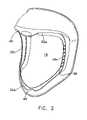
- FIG. 2is a front perspective view of the face shield assembly of FIG. 1 without the protective element;
- FIG. 3is a perspective view of one embodiment of the protective element of FIG. 1 ;
- FIG. 4Ais a perspective view of the face shield of FIG. 1 showing insertion of the protective element within the frame;
- FIG. 4Bis a partially enlarged view of the face shield of FIG. 4A showing insertion of the protective element within the right side of the frame;
- FIG. 5is a partially enlarged view of the face shield of FIG. 1 showing insertion of the protective element within the top of the frame;
- FIG. 6is a partially enlarged view of the face shield of FIG. 1 showing insertion of the protective element within the bottom of the frame;
- FIG. 7is a partially enlarged view of the face shield of FIG. 1 showing insertion of the protective element within the left side of the frame;
- FIG. 8is a left side view of the embodiment of FIG. 1 ;
- FIG. 9is a front view of the embodiment of FIG. 1 ;
- FIG. 10is a cross-sectional view taken along lines 10 — 10 of FIG. 9 ;
- FIG. 11is a cross-sectional view taken along lines 11 — 11 of FIG. 9 ;
- FIG. 12is a cross-sectional view taken along lines 12 — 12 of FIG. 9 ;
- FIG. 13is a rear perspective view of the face shield assembly of FIG. 1 mounted to a support structure;
- FIG. 14is a rear view of the face shield assembly of FIG. 13 ;
- FIG. 15is a perspective view of the support structure of FIG. 13 without the face shield;
- FIG. 16is an enlarged, exploded view of the mounting device of the support structure of FIG. 13 ;
- FIG. 17is an enlarged, partial side view of the ratchet mechanism for the support structure of FIG. 13 in the first or lowered position;
- FIG. 18is a side view of the ratchet mechanism for the support structure of FIG. 13 in the second or upper position;
- FIG. 19is a side view illustrating the face shield mounted to a distal mounting hole of the support structure
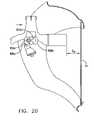
- FIG. 20is a side view illustrating the face shield mounted to a proximal mounting hole of the support structure in the lowered position
- FIG. 21is a side view illustrating the face shield mounted to a proximal mounting hole of the support structure in the upper position.
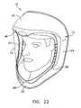
- FIG. 22is a perspective view of the face shield assembly on a user.
- FIGS. 1–22A face shield assembly for protecting a user's eyes and face is illustrated in FIGS. 1–22 .
- the face shield assembly 10includes a frame 12 and a protective element 14 that is removably supported in an opening 16 of the frame.
- the assemblymay also include a head worn support structure 18 for supporting the frame in an upper and lower position, as described in greater detail below.
- the frame 12preferably includes a top portion 20 , a bottom portion 22 , and side portions 24 .
- the top portionrests adjacent the forehead and top of the head of a user, while the bottom portion lies adjacent the jaw of the user, and the side portions are disposed adjacent the ears of the user ( FIG. 19 ).
- the top, bottom and side portionsare preferably fabricated as a single, unitary member out of a lightweight material, for example polycarbonate or nylon although other lightweight materials may be utilized, as would be known to those of skill in the art.
- An opening 16that is bounded by an inner edge 25 a , 25 b and 25 c of the top, bottom and side portions, respectively, of the frame is also provided.
- the opening 16is sized to receive the protective element 14 and preferably extends from a centerline of the face shield toward the edges of the face shield, so that the frame 12 does not obstruct the peripheral vision of the user.
- the protective element 14may be a lens made of a substantially transparent material, may be a mesh having very fine openings, or may be made of any other suitable material known in the art.
- the protective element 14is preferably formed as a single, unitary member having a shape defined by an outer edge 28 ( FIG. 3 ), which is preferably continuous. Because the protective element 14 is supported within the frame 12 without the use of fasteners, there is no need for any openings for receiving fasteners in the protective element 14 .
- the protective elementis a lens 15 , the lens preferably being substantially planar (i.e. flat) in the uninstalled position.
- the lens 15is preferably injection molded into a sheet made of, for example, polycarbonate, acrylic, polyester, or any other of a variety of materials that are well known in the art. Alternately, the lens may not be flat in the uninstalled configuration and may be molded into a spherical or other rounded shape (not shown).
- the lens 15may also be coated with a variety of chemical coatings, depending upon the particular application.
- the lensmay include an anti-fog coating, a reflective coating, may have a coating applied to improve the chemical and/or scratch resistance of the lens, or any other coating as is well known in the art.
- the lensis preferably shaped and sized to fit into the shape and size opening provided in the frame.
- the lensincludes a slightly arcuate upper edge 30 , side edges 32 , which curve slightly inward from the ends 31 a , 31 b of the upper edge, and a lower edge 34 that defines a semi-circular protrusion 36 .
- a variety of shaped lenses (or protective elements)may be utilized, depending upon the shape of the corresponding opening, as described above.
- the lensis sufficiently flexible so that it curves without fracturing when placed within the opening of the face shield frame 12 .
- Protective element 14is removably secured within the frame by a groove or channel 38 that is preferably formed between the inner edges 25 a,b,c , of the top, bottom and side portions and a lip 40 .
- the channel 38is formed between the inner edges 25 a–c of the frame 12 and the lip 40 , and is sized to receive the edges of the protective element 14 .
- a plurality of fingers or ridges 42 supported on an inner surface 44 of the lip 40are preferably provided (See FIG. 7 ).
- the ridges 42also aid in the manufacturing process of the shell by making the lip more rigid. Any suitable number of ridges may be provided, as desired.
- the lip 40 and ridges 42may also be formed as a single, unitary piece with the remaining portion of the frame. Alternately, the pieces may be formed as separate members and joined in any manner, as known to those of skill in the art.
- an upper detent 46 and a lower detent 48are also preferably provided.
- the upper and lower detentsmay be approximately centered on the top inner edge 25 a and bottom inner edge 25 b , respectively, of the frame. During use, the detents aid in placement and securing of the protective element 14 within the opening 16 .
- Both the upper detent 46 and the lower detent 48may include one or more ridges 47 to help secure the lens.
- the usermay readily replace the protective element even with gloved hands. For example, if the lens is damaged it may be replaced, or if the user is changing applications a lens having different characteristics may be replaced for the existing lens.
- the inserting and removing the lensis simple and intuitive, even during the user's first replacement or insertion. This is true, at least in part, because once the edges are inserted within the channel the lens is self locating. In other words, there is no need for a specific alignment in order to place holes in a proper position with corresponding fasteners.
- a head worn support structure 18may be provided.
- the support structuremay preferably be an adjustable strap style suspension system that fits onto the head of the user.
- Such an exemplary systemis shown in greater detail in FIGS. 10–17 .
- other types of support structuresfor example hat style structures, may be utilized as is known in the art.
- the support structure 18 of the present embodimentpreferably includes a first, adjustable strap 50 that extends around the circumference of the user's head during operation, and a second, adjustable strap 52 that extends over a top portion of the user's head during use.
- adjustable circumferential and top strapsare known in the art and may be adjusted in any of a variety of known ways.
- a knob 54may be provided to adjust the size of the circumferential strap 50
- a buckle style adjustment 56may be utilized to adjust the top strap 52 , as shown in the present embodiment. The adjustability allows for a more comfortable, custom fit of the support structure on the head of the user.
- Mounting members 58are preferably provided to mount the support structure 18 on either side 24 of the inner surface of the frame 12 .
- a fixed mounting element 59having a plurality of mounting holes 61 is secured to the inner surface of either side of the frame.
- a corresponding, adjustable mounting element 63is supported on either side of the support structure.
- the corresponding adjustable mounting elementsare supported below the juncture of the adjustable straps 50 , 52 .
- a pair of mounting holes 60 a, bmay be provided on the adjustable mounting element 63 so that the frame may be selectively positioned relative to the user's face.
- a pair of knobs 62each having a pin (not shown) are preferably utilized to support the adjustable mounting elements to the frame.
- a gap, “G p ”is formed between the user's face and an inner surface of the protective element 14 .
- the distance between the user's face and the inner surface of the protective elementis greater for G D than for G p . This allows the user to choose a specific spacing, as desired, during a particular operation. For example, if the user is wearing goggles with the face shield (as is common for many applications) then the user will probably choose to use the distal mounting hole 60 b in order to create a greater gap and, hence, room for the goggles.
- the mounting members 58also preferably include a pin 64 that is selectively engageable with at least two notches 66 a , 66 b formed in the mounting member in order to restrain the face shield in either the upper or lower positions.
- the pinis supported on the fixed mounting element and the at least two notches are formed in the adjustable mounting element, although the reverse configuration may also be utilized.
- a pair of stops 68 a , 68 bmay also be provided in order to limit the movement of the face shield during use.
- the face shieldis supported on the support structure by the distal mounting hole 60 b and is in the lowered position, i.e. is covering the face of the user.
- the pin 64is received within first notch 66 a .
- the userwould lift the face shield in the direction of arrow “B” ( FIG. 15 ) thus moving the pin out of the first notch 66 a and into engagement with stop 68 b .
- the pin 64would be in engagement with stop 68 a ( FIG. 17 ).
- the pinwould move into the second notch 66 b . In this manner, the face shield is supported in either the upper or lower position until moved by the user.
- the straps of the support structureis adjusted to fit the head of the user.
- the usercan then chose to engage either the distal or proximal mounting holes in order to position the lens relative to their face, as desired.
- the lensmay then be inserted within the opening in the frame by first inserting a side edge of the lens into a corresponding portion in the frame channel, and likewise inserting the top and bottom edges of the lens into the corresponding portion of the frame channel.
- the lensis also preferably positioned such that the central portion of the upper edge of the lens is behind the upper detent of the frame and the central portion of the lower edge of the lens is behind a lower detent of the frame.
- a continuous surfaceif formed to cover the opening in the frame and protect the user against unwanted hazards.
- the usermay then selectively raise and lower the face shield frame, as desired, with at least two notches and stops holding the frame in position and limiting movement of the shield.
- the face shield assembly disclosed hereinhas few moving parts and fasteners making it both easy to use and lightweight.
- the lightweight configuration and adjustabilityalso make it comfortable to wear over extended periods.
- the lensis easy to replace and provides good visibility.
- the face shield assemblymay also be readily adapted for use with other safety equipment. For example, a detent or snap may be placed on the top of the frame for connection with a hood and/or respirator.
Landscapes
- Health & Medical Sciences (AREA)
- Otolaryngology (AREA)
- Ophthalmology & Optometry (AREA)
- Engineering & Computer Science (AREA)
- Biomedical Technology (AREA)
- Heart & Thoracic Surgery (AREA)
- Vascular Medicine (AREA)
- Life Sciences & Earth Sciences (AREA)
- Animal Behavior & Ethology (AREA)
- General Health & Medical Sciences (AREA)
- Public Health (AREA)
- Veterinary Medicine (AREA)
- Helmets And Other Head Coverings (AREA)
Abstract
Description
Claims (25)
Priority Applications (4)
| Application Number | Priority Date | Filing Date | Title |
|---|---|---|---|
| US10/700,940US7007306B2 (en) | 2003-11-04 | 2003-11-04 | Face shield assembly |
| US10/868,525US7120939B1 (en) | 2003-11-04 | 2004-06-15 | Support for a face shield |
| EP04256845AEP1529505B1 (en) | 2003-11-04 | 2004-11-04 | Face shield assembly |
| DE602004029320TDE602004029320D1 (en) | 2003-11-04 | 2004-11-04 | Face shield device |
Applications Claiming Priority (1)
| Application Number | Priority Date | Filing Date | Title |
|---|---|---|---|
| US10/700,940US7007306B2 (en) | 2003-11-04 | 2003-11-04 | Face shield assembly |
Related Child Applications (1)
| Application Number | Title | Priority Date | Filing Date |
|---|---|---|---|
| US10/868,525Continuation-In-PartUS7120939B1 (en) | 2003-11-04 | 2004-06-15 | Support for a face shield |
Publications (2)
| Publication Number | Publication Date |
|---|---|
| US20050091732A1 US20050091732A1 (en) | 2005-05-05 |
| US7007306B2true US7007306B2 (en) | 2006-03-07 |
Family
ID=34435525
Family Applications (2)
| Application Number | Title | Priority Date | Filing Date |
|---|---|---|---|
| US10/700,940Expired - LifetimeUS7007306B2 (en) | 2003-11-04 | 2003-11-04 | Face shield assembly |
| US10/868,525Expired - Fee RelatedUS7120939B1 (en) | 2003-11-04 | 2004-06-15 | Support for a face shield |
Family Applications After (1)
| Application Number | Title | Priority Date | Filing Date |
|---|---|---|---|
| US10/868,525Expired - Fee RelatedUS7120939B1 (en) | 2003-11-04 | 2004-06-15 | Support for a face shield |
Country Status (3)
| Country | Link |
|---|---|
| US (2) | US7007306B2 (en) |
| EP (1) | EP1529505B1 (en) |
| DE (1) | DE602004029320D1 (en) |
Cited By (30)
| Publication number | Priority date | Publication date | Assignee | Title |
|---|---|---|---|---|
| US20070245467A1 (en)* | 2006-04-18 | 2007-10-25 | 3M Innovative Properties Company | Head Suspension System And Headgear That Have An Adjustable Visor And Method Of Adjusting Same |
| US20070245466A1 (en)* | 2006-04-18 | 2007-10-25 | 3M Innovative Properties Company | Head Suspension System And Headgear With Replaceable Headband Bridge And Method Of Adjusting Same |
| USD584010S1 (en)* | 2008-04-03 | 2008-12-30 | 3M Innovative Properties Company | Jaw frame for headgear article |
| USD587858S1 (en)* | 2008-04-03 | 2009-03-03 | 3M Innovative Properties Company | Visor frame for headgear article |
| USD590547S1 (en)* | 2008-04-03 | 2009-04-14 | 3M Innovative Properties Company | Headgear article having recessed portions |
| USD590548S1 (en)* | 2008-04-03 | 2009-04-14 | 3M Innovative Properties Company | Breathing tube connection for respiratory protection system |
| USD612544S1 (en)* | 2008-04-03 | 2010-03-23 | 3M Innovative Properties Company | Visor frame for headgear article |
| US20100229286A1 (en)* | 2007-10-10 | 2010-09-16 | Lars-Olov Ahlgren | Head Suspension Having Transition Arms and Rear Support |
| US20110048416A1 (en)* | 2008-04-04 | 2011-03-03 | Brace Thomas J | Respirator System Including Convertible Head Covering Member |
| US8161576B2 (en) | 2007-02-01 | 2012-04-24 | Sellstrom Manufacturing Company | Protective headgear assembly |
| USD658812S1 (en)* | 2010-02-12 | 2012-05-01 | Alphamicron, Inc. | Optical element for a helmet visor |
| US8225421B1 (en) | 2006-05-03 | 2012-07-24 | Sperian Eye & Face Protection, Inc. | Face shield |
| US8261375B1 (en) | 2003-06-19 | 2012-09-11 | Reaux Brian K | Method of forming a protective covering for the face and eyes |
| US20130031693A1 (en)* | 2011-08-03 | 2013-02-07 | Honeywell International, Inc. | Universal dual-pivot face shield assembly for a hard hat |
| USD681282S1 (en)* | 2010-09-30 | 2013-04-30 | Degil Safety Products (1989) Inc. | Industrial face-shield |
| US8850624B2 (en)* | 2011-05-23 | 2014-10-07 | Honeywell International, Inc. | Headgear with a spring buffered occipital cradle |
| US9335565B2 (en) | 2009-01-30 | 2016-05-10 | Alphamicron Incorporated | Attachable optical element arrangements and methods |
| USD778507S1 (en)* | 2015-08-11 | 2017-02-07 | Brian K. Reaux | Medical cooling personal protection helmet with camera casing and mounting attachment assembly |
| US9918508B2 (en) | 2012-11-13 | 2018-03-20 | Alphamicron Incorporated | Attachable optical element arrangements and methods |
| USD881380S1 (en) | 2017-10-16 | 2020-04-14 | Gentex Corporation | Respirator |
| USD931549S1 (en) | 2020-03-11 | 2021-09-21 | Lincoln Global, Inc | Chin guard for a face shield |
| US20210345721A1 (en)* | 2020-05-08 | 2021-11-11 | Milwaukee Electric Tool Corporation | Non-Impact Construction Face Shield |
| USD936908S1 (en) | 2020-06-09 | 2021-11-23 | Lincoln Global, Inc. | Chin guard for a face shield |
| US11553743B2 (en)* | 2020-07-11 | 2023-01-17 | Art Rubio | Personal shield |
| US11617403B2 (en) | 2020-05-26 | 2023-04-04 | Ford Global Technologies, Llc | Face shield manufacturing method and assembly |
| US11647799B2 (en) | 2020-08-03 | 2023-05-16 | Ford Global Technologies, Llc | Face shield assembly |
| US11937660B2 (en) | 2021-02-08 | 2024-03-26 | Milwaukee Electric Tool Corporation | Hard hat face shield attachment system |
| US12035765B2 (en)* | 2019-05-28 | 2024-07-16 | Honeywell International Inc. | Protective face shield assembly |
| US20240315382A1 (en)* | 2023-03-10 | 2024-09-26 | Alan Carlson | Adjustable Head Engaging Apparatus with Display |
| US12156560B2 (en) | 2021-03-12 | 2024-12-03 | Milwaukee Electric Tool Corporation | Safety headwear systems and accessories |
Families Citing this family (50)
| Publication number | Priority date | Publication date | Assignee | Title |
|---|---|---|---|---|
| US7007306B2 (en)* | 2003-11-04 | 2006-03-07 | Bacou-Dalloz Eye & Face Protection, Inc. | Face shield assembly |
| US7594151B2 (en)* | 2004-06-18 | 2009-09-22 | Qualcomm, Incorporated | Reverse link power control in an orthogonal system |
| JP4447999B2 (en)* | 2004-10-01 | 2010-04-07 | キヤノン株式会社 | Head mounting device and head mounting system |
| NZ701722A (en) | 2006-07-28 | 2016-07-29 | Resmed Ltd | Delivery of respiratory therapy |
| EP2428241B1 (en) | 2006-07-28 | 2016-07-06 | ResMed Limited | Delivery of respiratory therapy |
| EP2481434B1 (en)* | 2006-12-15 | 2016-04-13 | ResMed Ltd. | Delivery of respiratory therapy |
| USD581104S1 (en)* | 2007-05-24 | 2008-11-18 | Kenneth Fang | Hatband |
| USD581103S1 (en)* | 2007-05-24 | 2008-11-18 | Kenneth Fang | Hatband |
| AU2008311041B2 (en)* | 2007-10-10 | 2012-03-22 | 3M Innovative Properties Company | Pivoting headgear system |
| CA125941S (en)* | 2007-11-15 | 2009-01-27 | 3M Innovative Properties Co | Protective plate for a welding filter in a welding helmet |
| JP5268801B2 (en)* | 2009-06-26 | 2013-08-21 | キヤノン株式会社 | Head-mounted display device |
| USD666778S1 (en)* | 2010-03-10 | 2012-09-04 | 3M Innovative Properties Company | Welding helmet feature contour |
| WO2011141733A1 (en)* | 2010-05-11 | 2011-11-17 | Scott Health & Safety Limited | Headgear support device having front-back adjustment |
| KR101253075B1 (en)* | 2010-12-13 | 2013-04-10 | 주식회사 오토스윙 | Head band |
| US10419861B2 (en) | 2011-05-24 | 2019-09-17 | Cochlear Limited | Convertibility of a bone conduction device |
| US8336114B1 (en)* | 2011-08-12 | 2012-12-25 | Shih-Min Lee | Protective mask |
| US9179729B2 (en)* | 2012-03-13 | 2015-11-10 | Boa Technology, Inc. | Tightening systems |
| US9021616B2 (en)* | 2012-04-25 | 2015-05-05 | David Baty | Protective gear |
| US9049527B2 (en) | 2012-08-28 | 2015-06-02 | Cochlear Limited | Removable attachment of a passive transcutaneous bone conduction device with limited skin deformation |
| US9998687B2 (en)* | 2012-09-12 | 2018-06-12 | Bae Systems Information And Electronic Systems Integration Inc. | Face mounted extreme environment thermal sensor system |
| US9554610B2 (en)* | 2012-10-11 | 2017-01-31 | Honeywell International, Inc. | Protective headgear assembly |
| US9999546B2 (en) | 2014-06-16 | 2018-06-19 | Illinois Tool Works Inc. | Protective headwear with airflow |
| US10299530B2 (en) | 2014-06-16 | 2019-05-28 | Illinois Tool Works Inc. | Headgear for protective headwear |
| US11033433B2 (en) | 2014-06-16 | 2021-06-15 | Illinois Tool Works Inc | Removable shield for protective headwear |
| AT516055B1 (en)* | 2014-08-06 | 2016-02-15 | Rosenbauer Int Ag | helmet |
| US10702003B2 (en)* | 2014-12-26 | 2020-07-07 | Illinois Tool Works Inc. | Apparatus for reducing angular velocity of protective shells associated with protective headwear |
| USD767829S1 (en)* | 2015-02-04 | 2016-09-27 | Tecmen Electronics Co., Ltd. | Belt for welding helmet |
| USD776359S1 (en) | 2015-05-12 | 2017-01-10 | Illinois Tool Works Inc. | Protective helmet |
| USD777987S1 (en) | 2015-05-12 | 2017-01-31 | Illinois Tool Works Inc. | Protective helmet |
| USD769535S1 (en) | 2015-05-12 | 2016-10-18 | Illinois Tool Works Inc. | Protective helmet |
| USD776360S1 (en) | 2015-05-12 | 2017-01-10 | Illinois Tool Works Inc. | Protective helmet |
| USD770689S1 (en) | 2015-05-12 | 2016-11-01 | Illinois Tool Works Inc. | Protective helmet |
| USD782120S1 (en) | 2015-05-12 | 2017-03-21 | Illinois Tool Works Inc. | Protective helmet |
| USD769542S1 (en) | 2015-05-12 | 2016-10-18 | Illinois Tool Works Inc. | Protective helmet |
| USD769543S1 (en) | 2015-05-12 | 2016-10-18 | Illinois Tool Works Inc. | Protective helmet |
| US9814622B2 (en) | 2015-06-12 | 2017-11-14 | Illinois Tool Works Inc. | Bump cap for face protection members |
| US20160360820A1 (en) | 2015-06-12 | 2016-12-15 | Illinois Tool Works Inc. | Hard Hat Adapter for a Welding Face Member |
| JP2017011436A (en)* | 2015-06-19 | 2017-01-12 | セイコーエプソン株式会社 | Image display device |
| USD781502S1 (en) | 2016-05-20 | 2017-03-14 | Illinois Tool Works Inc. | Protective helmet |
| USD779128S1 (en)* | 2016-05-20 | 2017-02-14 | Illinois Tool Works Inc. | Protective helmet |
| CN107076996B (en)* | 2016-09-27 | 2018-10-26 | 深圳市大疆创新科技有限公司 | video glasses |
| WO2019006462A1 (en)* | 2017-06-30 | 2019-01-03 | Fulton Bowman Lee | Visor coating film, protected eyewear apparatus, and application kit |
| TWI680308B (en)* | 2017-11-03 | 2019-12-21 | 宏達國際電子股份有限公司 | Head-mounted display device |
| TWI663428B (en)* | 2018-08-01 | 2019-06-21 | 宏星技術股份有限公司 | Head-mounted display |
| CN110794579B (en)* | 2018-08-01 | 2022-05-03 | 宏星技术股份有限公司 | Head-mounted display device |
| US12256057B2 (en) | 2019-12-31 | 2025-03-18 | ResMed Asia Pte. Ltd. | Positioning, stabilising, and interfacing structures and system incorporating same |
| US12178276B2 (en) | 2020-03-27 | 2024-12-31 | ResMed Pty Ltd | Positioning and stabilising structure and system incorporating same |
| US11598967B2 (en)* | 2020-03-27 | 2023-03-07 | ResMed Pty Ltd | Positioning and stabilising structure and system incorporating same |
| US11686948B2 (en)* | 2020-03-27 | 2023-06-27 | ResMed Pty Ltd | Positioning, stabilising, and interfacing structures and system incorporating same |
| DE202020001450U1 (en) | 2020-03-28 | 2020-04-30 | SEUFERT - Gesellschaft für transparente Verpackungen mbH | Face mask to cover the face of a human user |
Citations (25)
| Publication number | Priority date | Publication date | Assignee | Title |
|---|---|---|---|---|
| US2326376A (en)* | 1943-02-17 | 1943-08-10 | Ronald Muller | Welder's hood |
| US2631287A (en)* | 1950-09-30 | 1953-03-17 | Chicago Eye Shield Company | Face protector |
| US3075201A (en)* | 1960-12-09 | 1963-01-29 | Welsh Mfg Co | Headband assembly for welder's helmet |
| US3212101A (en)* | 1963-03-05 | 1965-10-19 | Air Reduction | Protective helmet having removable paning |
| US3259908A (en) | 1964-04-13 | 1966-07-12 | Electric Storage Battery Co | Faceshield clip-on visor |
| US3789428A (en) | 1971-10-29 | 1974-02-05 | W Martin | Face protector |
| US4076373A (en) | 1976-03-10 | 1978-02-28 | E. D. Bullard Company | Method of and means for shielding the lens of a face mask |
| US4097929A (en) | 1976-05-14 | 1978-07-04 | Racal-Amplivox Communications Ltd. | Protective visor means for a helmet |
| US4101980A (en) | 1975-04-26 | 1978-07-25 | Uvex Winter Optik Gmbh | Protective device having a shield for protecting the face of a user |
| US4462119A (en) | 1981-09-18 | 1984-07-31 | Drag Specialties, Inc. | Face shield and helmet |
| US4507809A (en) | 1981-12-23 | 1985-04-02 | Uvex Winter Optik Gmbh | Visor for a protective helmet |
| US4536892A (en)* | 1984-04-23 | 1985-08-27 | Mine Safety Appliances Company | Riot faceshield assembly |
| US4542538A (en) | 1984-01-26 | 1985-09-24 | E. D. Bullard Company | Disposable protective film accessory for the lens of a respirator hood |
| US4748697A (en)* | 1987-03-26 | 1988-06-07 | Hodnett Jack L | Face mask with interchangeable lenses |
| US4748695A (en) | 1986-05-12 | 1988-06-07 | Shigematsu Works Co., Ltd. | Face shield assembly |
| US4888831A (en) | 1988-06-10 | 1989-12-26 | E. D. Bullard Company | Adjustable head band suspension system for use with hard hat shell |
| USD320870S (en) | 1989-08-29 | 1991-10-15 | Parmelee Industries, Inc. | Headgear for faceshield |
| US5077836A (en) | 1987-11-02 | 1992-01-07 | Bilsom Ab | Headgear |
| US5410757A (en) | 1990-06-01 | 1995-05-02 | Kemira Oy | Face shield |
| US5571217A (en)* | 1992-07-24 | 1996-11-05 | Optrel Ag | Protective assembly for the protection of the human head |
| US5793449A (en) | 1993-05-10 | 1998-08-11 | Optrel Ag | Protective device |
| USD416649S (en) | 1998-03-10 | 1999-11-16 | 3M Innovative Properties Company | Face shield with protective lens |
| US6102033A (en) | 1998-03-10 | 2000-08-15 | 3M Innovative Properties Company | Attachment system for replacement helmet respirator lens |
| US6260197B1 (en)* | 1999-04-09 | 2001-07-17 | Jackson Products, Inc. | Welding helmet with conical pivoting mechanism for head gear strap |
| US6317895B1 (en) | 1999-02-26 | 2001-11-20 | Mine Safety Appliances Company | Safety helmet assembly |
Family Cites Families (30)
| Publication number | Priority date | Publication date | Assignee | Title |
|---|---|---|---|---|
| US631880A (en)* | 1898-12-23 | 1899-08-29 | Charles Josiah Ross | Helmet. |
| US1601830A (en)* | 1924-10-09 | 1926-10-05 | Francis D Huntsman | Welder's mask |
| US2194492A (en)* | 1938-11-15 | 1940-03-26 | Bowers Charles Evans | Face and head protective device |
| US2272833A (en)* | 1940-07-11 | 1942-02-10 | Charles H Dockson | Protective device |
| US2283120A (en) | 1940-12-14 | 1942-05-12 | Chicago Eye Shield Company | Welder's shield |
| US2320244A (en)* | 1940-12-31 | 1943-05-25 | Fibre Metal Products Company | Adjustable headgear connection for helmets |
| US2390006A (en)* | 1942-06-08 | 1945-11-27 | American Optical Corp | Welder's helmet |
| US2360482A (en)* | 1943-07-08 | 1944-10-17 | Mine Safety Appliances Co | Face shield |
| US2396239A (en)* | 1943-12-09 | 1946-03-12 | Edward R Beck | Welder's shield |
| US2445203A (en)* | 1945-01-15 | 1948-07-13 | Fibre Metal Products Company | Headgear goggles |
| US2397722A (en)* | 1945-01-19 | 1946-04-02 | Fibre Metal Products Company | Face protective device |
| US2526582A (en)* | 1946-03-28 | 1950-10-17 | Rowan James | Goggles |
| US2594335A (en)* | 1946-10-07 | 1952-04-29 | Parmelee Plastics Co | Hinged structure |
| US2658200A (en)* | 1951-09-22 | 1953-11-10 | Fibre Metal Products Company | Adjustable stop for pivotally mounted head protective equipment |
| US2763006A (en)* | 1953-10-12 | 1956-09-18 | Fendall Co | Face shield |
| US2758307A (en)* | 1954-09-15 | 1956-08-14 | Kenneth L Treiber | Face shield |
| US3047876A (en)* | 1958-12-08 | 1962-08-07 | Chicago Eye Shield Company | Adjustable head piece |
| US3026525A (en)* | 1959-08-04 | 1962-03-27 | Gyorfy Julius | Protective helmet |
| US3181532A (en)* | 1963-04-22 | 1965-05-04 | Artell L Harris | Sand blaster's helmet |
| US3430262A (en)* | 1966-09-12 | 1969-03-04 | Bullard Co | Welder's face shield mounting bracket for safety hats |
| US3430263A (en)* | 1967-07-19 | 1969-03-04 | Welsh Mfg Co | Universal stop pin for head protective equipment |
| US3555560A (en)* | 1969-01-16 | 1971-01-19 | Bullard Co | Suspension system for safety hat |
| US3696442A (en)* | 1969-11-03 | 1972-10-10 | Fendall Co | Protective faceshield |
| US4056852A (en)* | 1976-04-19 | 1977-11-08 | The United States Of America As Represented By The Secretary Of The Army | Adjustable helmet suspension system |
| US4464800A (en)* | 1982-08-20 | 1984-08-14 | Edwards David B | Attachment device for mounting face-protective shields on headgear |
| EP0353929A1 (en)* | 1988-08-02 | 1990-02-07 | Hellberg Protection Ab | Spectacles |
| DE59207799D1 (en)* | 1991-10-04 | 1997-02-13 | Zeiss Carl Fa | Headband for a measuring, lighting or observation unit |
| US5996129A (en)* | 1998-04-30 | 1999-12-07 | Lopez; Jose A. | Goggles |
| US6154881A (en) | 1999-09-22 | 2000-12-05 | Lee; Yhan G. | Face protector |
| US7007306B2 (en)* | 2003-11-04 | 2006-03-07 | Bacou-Dalloz Eye & Face Protection, Inc. | Face shield assembly |
- 2003
- 2003-11-04USUS10/700,940patent/US7007306B2/ennot_activeExpired - Lifetime
- 2004
- 2004-06-15USUS10/868,525patent/US7120939B1/ennot_activeExpired - Fee Related
- 2004-11-04DEDE602004029320Tpatent/DE602004029320D1/ennot_activeExpired - Lifetime
- 2004-11-04EPEP04256845Apatent/EP1529505B1/ennot_activeExpired - Lifetime
Patent Citations (25)
| Publication number | Priority date | Publication date | Assignee | Title |
|---|---|---|---|---|
| US2326376A (en)* | 1943-02-17 | 1943-08-10 | Ronald Muller | Welder's hood |
| US2631287A (en)* | 1950-09-30 | 1953-03-17 | Chicago Eye Shield Company | Face protector |
| US3075201A (en)* | 1960-12-09 | 1963-01-29 | Welsh Mfg Co | Headband assembly for welder's helmet |
| US3212101A (en)* | 1963-03-05 | 1965-10-19 | Air Reduction | Protective helmet having removable paning |
| US3259908A (en) | 1964-04-13 | 1966-07-12 | Electric Storage Battery Co | Faceshield clip-on visor |
| US3789428A (en) | 1971-10-29 | 1974-02-05 | W Martin | Face protector |
| US4101980A (en) | 1975-04-26 | 1978-07-25 | Uvex Winter Optik Gmbh | Protective device having a shield for protecting the face of a user |
| US4076373A (en) | 1976-03-10 | 1978-02-28 | E. D. Bullard Company | Method of and means for shielding the lens of a face mask |
| US4097929A (en) | 1976-05-14 | 1978-07-04 | Racal-Amplivox Communications Ltd. | Protective visor means for a helmet |
| US4462119A (en) | 1981-09-18 | 1984-07-31 | Drag Specialties, Inc. | Face shield and helmet |
| US4507809A (en) | 1981-12-23 | 1985-04-02 | Uvex Winter Optik Gmbh | Visor for a protective helmet |
| US4542538A (en) | 1984-01-26 | 1985-09-24 | E. D. Bullard Company | Disposable protective film accessory for the lens of a respirator hood |
| US4536892A (en)* | 1984-04-23 | 1985-08-27 | Mine Safety Appliances Company | Riot faceshield assembly |
| US4748695A (en) | 1986-05-12 | 1988-06-07 | Shigematsu Works Co., Ltd. | Face shield assembly |
| US4748697A (en)* | 1987-03-26 | 1988-06-07 | Hodnett Jack L | Face mask with interchangeable lenses |
| US5077836A (en) | 1987-11-02 | 1992-01-07 | Bilsom Ab | Headgear |
| US4888831A (en) | 1988-06-10 | 1989-12-26 | E. D. Bullard Company | Adjustable head band suspension system for use with hard hat shell |
| USD320870S (en) | 1989-08-29 | 1991-10-15 | Parmelee Industries, Inc. | Headgear for faceshield |
| US5410757A (en) | 1990-06-01 | 1995-05-02 | Kemira Oy | Face shield |
| US5571217A (en)* | 1992-07-24 | 1996-11-05 | Optrel Ag | Protective assembly for the protection of the human head |
| US5793449A (en) | 1993-05-10 | 1998-08-11 | Optrel Ag | Protective device |
| USD416649S (en) | 1998-03-10 | 1999-11-16 | 3M Innovative Properties Company | Face shield with protective lens |
| US6102033A (en) | 1998-03-10 | 2000-08-15 | 3M Innovative Properties Company | Attachment system for replacement helmet respirator lens |
| US6317895B1 (en) | 1999-02-26 | 2001-11-20 | Mine Safety Appliances Company | Safety helmet assembly |
| US6260197B1 (en)* | 1999-04-09 | 2001-07-17 | Jackson Products, Inc. | Welding helmet with conical pivoting mechanism for head gear strap |
Cited By (41)
| Publication number | Priority date | Publication date | Assignee | Title |
|---|---|---|---|---|
| US8261375B1 (en) | 2003-06-19 | 2012-09-11 | Reaux Brian K | Method of forming a protective covering for the face and eyes |
| US7865968B2 (en) | 2006-04-18 | 2011-01-11 | 3M Innovative Properties Company | Head suspension system and headgear that have an adjustable visor and method of adjusting same |
| US20070245466A1 (en)* | 2006-04-18 | 2007-10-25 | 3M Innovative Properties Company | Head Suspension System And Headgear With Replaceable Headband Bridge And Method Of Adjusting Same |
| US8584265B2 (en) | 2006-04-18 | 2013-11-19 | 3M Innovative Properties Company | Head suspension system and headgear with replaceable headband bridge and method of adjusting same |
| US20070245467A1 (en)* | 2006-04-18 | 2007-10-25 | 3M Innovative Properties Company | Head Suspension System And Headgear That Have An Adjustable Visor And Method Of Adjusting Same |
| EP2007237A4 (en)* | 2006-04-18 | 2011-08-31 | 3M Innovative Properties Co | SUSPENSION SYSTEM FOR HEAD, HAIRSTYLE WITH ADJUSTABLE VISOR AND ITS ADJUSTMENT METHOD |
| US8225421B1 (en) | 2006-05-03 | 2012-07-24 | Sperian Eye & Face Protection, Inc. | Face shield |
| US8161576B2 (en) | 2007-02-01 | 2012-04-24 | Sellstrom Manufacturing Company | Protective headgear assembly |
| US8505121B2 (en) | 2007-10-10 | 2013-08-13 | 3M Innovative Properties Company | Head suspension having transition arms and rear support |
| US20100229286A1 (en)* | 2007-10-10 | 2010-09-16 | Lars-Olov Ahlgren | Head Suspension Having Transition Arms and Rear Support |
| US9066552B2 (en)* | 2007-10-10 | 2015-06-30 | 3M Innovative Properties Company | Head suspension having transition arms and rear support |
| US8745770B2 (en) | 2007-10-10 | 2014-06-10 | 3M Innovative Properties Company | Head suspension having transition arms and rear support |
| USD597260S1 (en)* | 2008-04-03 | 2009-07-28 | 3M Innovative Properties Company | Visor frame for headgear article |
| USD584010S1 (en)* | 2008-04-03 | 2008-12-30 | 3M Innovative Properties Company | Jaw frame for headgear article |
| USD612544S1 (en)* | 2008-04-03 | 2010-03-23 | 3M Innovative Properties Company | Visor frame for headgear article |
| USD590548S1 (en)* | 2008-04-03 | 2009-04-14 | 3M Innovative Properties Company | Breathing tube connection for respiratory protection system |
| USD590547S1 (en)* | 2008-04-03 | 2009-04-14 | 3M Innovative Properties Company | Headgear article having recessed portions |
| USD597710S1 (en)* | 2008-04-03 | 2009-08-04 | 3M Innovative Properties Company | Headgear article having recessed portions |
| USD587858S1 (en)* | 2008-04-03 | 2009-03-03 | 3M Innovative Properties Company | Visor frame for headgear article |
| US8534279B2 (en) | 2008-04-04 | 2013-09-17 | 3M Innovative Properties Company | Respirator system including convertible head covering member |
| US20110048416A1 (en)* | 2008-04-04 | 2011-03-03 | Brace Thomas J | Respirator System Including Convertible Head Covering Member |
| US9335565B2 (en) | 2009-01-30 | 2016-05-10 | Alphamicron Incorporated | Attachable optical element arrangements and methods |
| USD658812S1 (en)* | 2010-02-12 | 2012-05-01 | Alphamicron, Inc. | Optical element for a helmet visor |
| USD681282S1 (en)* | 2010-09-30 | 2013-04-30 | Degil Safety Products (1989) Inc. | Industrial face-shield |
| US9560893B2 (en) | 2011-05-23 | 2017-02-07 | Honeywell International, Inc. | Headgear with a spring buffered occipital cradle |
| US8850624B2 (en)* | 2011-05-23 | 2014-10-07 | Honeywell International, Inc. | Headgear with a spring buffered occipital cradle |
| US20130031693A1 (en)* | 2011-08-03 | 2013-02-07 | Honeywell International, Inc. | Universal dual-pivot face shield assembly for a hard hat |
| US8434167B2 (en)* | 2011-08-03 | 2013-05-07 | Honeywell International Inc. | Universal dual-pivot face shield assembly for a hard hat |
| US9918508B2 (en) | 2012-11-13 | 2018-03-20 | Alphamicron Incorporated | Attachable optical element arrangements and methods |
| USD778507S1 (en)* | 2015-08-11 | 2017-02-07 | Brian K. Reaux | Medical cooling personal protection helmet with camera casing and mounting attachment assembly |
| USD881380S1 (en) | 2017-10-16 | 2020-04-14 | Gentex Corporation | Respirator |
| US12035765B2 (en)* | 2019-05-28 | 2024-07-16 | Honeywell International Inc. | Protective face shield assembly |
| USD931549S1 (en) | 2020-03-11 | 2021-09-21 | Lincoln Global, Inc | Chin guard for a face shield |
| US20210345721A1 (en)* | 2020-05-08 | 2021-11-11 | Milwaukee Electric Tool Corporation | Non-Impact Construction Face Shield |
| US11617403B2 (en) | 2020-05-26 | 2023-04-04 | Ford Global Technologies, Llc | Face shield manufacturing method and assembly |
| USD936908S1 (en) | 2020-06-09 | 2021-11-23 | Lincoln Global, Inc. | Chin guard for a face shield |
| US11553743B2 (en)* | 2020-07-11 | 2023-01-17 | Art Rubio | Personal shield |
| US11647799B2 (en) | 2020-08-03 | 2023-05-16 | Ford Global Technologies, Llc | Face shield assembly |
| US11937660B2 (en) | 2021-02-08 | 2024-03-26 | Milwaukee Electric Tool Corporation | Hard hat face shield attachment system |
| US12156560B2 (en) | 2021-03-12 | 2024-12-03 | Milwaukee Electric Tool Corporation | Safety headwear systems and accessories |
| US20240315382A1 (en)* | 2023-03-10 | 2024-09-26 | Alan Carlson | Adjustable Head Engaging Apparatus with Display |
Also Published As
| Publication number | Publication date |
|---|---|
| DE602004029320D1 (en) | 2010-11-11 |
| US20050091732A1 (en) | 2005-05-05 |
| US7120939B1 (en) | 2006-10-17 |
| EP1529505A1 (en) | 2005-05-11 |
| EP1529505B1 (en) | 2010-09-29 |
Similar Documents
| Publication | Publication Date | Title |
|---|---|---|
| US7007306B2 (en) | Face shield assembly | |
| US6009555A (en) | Multiple component headgear system | |
| US20070033716A1 (en) | Goggles with removable frame and methods of making and using the same | |
| US8893314B2 (en) | Sport goggle with quick release lens | |
| EP2191736B1 (en) | Wearable protective device | |
| US5608917A (en) | Ergonomic head band apparatus | |
| US10226383B2 (en) | Welding helmet with removable neck guard | |
| US6666554B2 (en) | Protective eyewear kit | |
| US6481845B1 (en) | Eyewear with detachable lens portion | |
| US5410763A (en) | Eyeshield with detachable components | |
| US9949517B2 (en) | Medical face shield | |
| US20110296574A1 (en) | Protective Eyewear Including Auxiliary Lenses | |
| US6996846B1 (en) | Visor-type face shield for dentist | |
| JP2009534547A (en) | Headrest system having replaceable headband bridge, headgear, and adjustment method thereof | |
| JP2009534120A (en) | Head suspension system having adjustable visor, headgear, and adjustment method thereof | |
| US5926854A (en) | Protective helmet and eye protector assembly having fabric panel forming fabric cover for eye protector | |
| JP6826357B1 (en) | Face guard | |
| JP2021195635A (en) | Face shield | |
| US20210360997A1 (en) | Transparent Protective Face Mask | |
| EP4213674B1 (en) | Chin protector, assembly and kit of parts therewith and method of retrofitting a chin protector | |
| US20050190549A1 (en) | Eye and face shield with attached lamp | |
| US7293560B2 (en) | Respirator mask with supplementary panels | |
| US9883972B2 (en) | Eye protection goggles | |
| WO2019032513A1 (en) | Eyewear and related methods | |
| US20080078006A1 (en) | Side Shield |
Legal Events
| Date | Code | Title | Description |
|---|---|---|---|
| AS | Assignment | Owner name:BACOU-DALLOZ USA SAFETY, INC., RHODE ISLAND Free format text:ASSIGNMENT OF ASSIGNORS INTEREST;ASSIGNORS:HOWARD, JEREMY CONRAD;MICHAS, LUKE WILLIAM;CANAVAN, RICHARD W.;AND OTHERS;REEL/FRAME:014671/0580 Effective date:20031010 | |
| AS | Assignment | Owner name:BACOU-DALLOZ EYE & FACE PROTECTION, INC., RHODE IS Free format text:ASSIGNMENT OF ASSIGNORS INTEREST;ASSIGNOR:BACOU-DALLOZ USA SAFETY, INC., FORMERLY KNOWN AS BACOU USA SAFETY, INC.;REEL/FRAME:014926/0255 Effective date:20040628 | |
| STCF | Information on status: patent grant | Free format text:PATENTED CASE | |
| AS | Assignment | Owner name:SPERIAN EYE & FACE PROTECTION, INC., RHODE ISLAND Free format text:CHANGE OF NAME;ASSIGNOR:BACOU-DALLOZ EYE & FACE PROTECTION, INC.;REEL/FRAME:019725/0895 Effective date:20070820 | |
| FPAY | Fee payment | Year of fee payment:4 | |
| FEPP | Fee payment procedure | Free format text:PAYOR NUMBER ASSIGNED (ORIGINAL EVENT CODE: ASPN); ENTITY STATUS OF PATENT OWNER: LARGE ENTITY | |
| FPAY | Fee payment | Year of fee payment:8 | |
| AS | Assignment | Owner name:SPERIAN PROTECTION AMERICAS, INC., RHODE ISLAND Free format text:MERGER;ASSIGNOR:SPERIAN EYE & FACE PROTECTION, INC.;REEL/FRAME:033917/0554 Effective date:20131220 | |
| AS | Assignment | Owner name:HONEYWELL SAFETY PRODUCTS USA, INC., RHODE ISLAND Free format text:CHANGE OF NAME;ASSIGNOR:SPERIAN PROTECTION AMERICAS, INC.;REEL/FRAME:033951/0056 Effective date:20140101 | |
| MAFP | Maintenance fee payment | Free format text:PAYMENT OF MAINTENANCE FEE, 12TH YEAR, LARGE ENTITY (ORIGINAL EVENT CODE: M1553) Year of fee payment:12 |