US7007141B2 - Archival data storage system and method - Google Patents
Archival data storage system and methodDownload PDFInfo
- Publication number
- US7007141B2 US7007141B2US10/061,081US6108102AUS7007141B2US 7007141 B2US7007141 B2US 7007141B2US 6108102 AUS6108102 AUS 6108102AUS 7007141 B2US7007141 B2US 7007141B2
- Authority
- US
- United States
- Prior art keywords
- archival storage
- disk
- storage unit
- archival
- spin
- Prior art date
- Legal status (The legal status is an assumption and is not a legal conclusion. Google has not performed a legal analysis and makes no representation as to the accuracy of the status listed.)
- Expired - Lifetime, expires
Links
Images


Classifications
- G—PHYSICS
- G06—COMPUTING OR CALCULATING; COUNTING
- G06F—ELECTRIC DIGITAL DATA PROCESSING
- G06F3/00—Input arrangements for transferring data to be processed into a form capable of being handled by the computer; Output arrangements for transferring data from processing unit to output unit, e.g. interface arrangements
- G06F3/06—Digital input from, or digital output to, record carriers, e.g. RAID, emulated record carriers or networked record carriers
- G06F3/0601—Interfaces specially adapted for storage systems
- G06F3/0628—Interfaces specially adapted for storage systems making use of a particular technique
- G06F3/0646—Horizontal data movement in storage systems, i.e. moving data in between storage devices or systems
- G06F3/0647—Migration mechanisms
- G—PHYSICS
- G06—COMPUTING OR CALCULATING; COUNTING
- G06F—ELECTRIC DIGITAL DATA PROCESSING
- G06F11/00—Error detection; Error correction; Monitoring
- G06F11/07—Responding to the occurrence of a fault, e.g. fault tolerance
- G06F11/08—Error detection or correction by redundancy in data representation, e.g. by using checking codes
- G06F11/10—Adding special bits or symbols to the coded information, e.g. parity check, casting out 9's or 11's
- G06F11/1076—Parity data used in redundant arrays of independent storages, e.g. in RAID systems
- G—PHYSICS
- G06—COMPUTING OR CALCULATING; COUNTING
- G06F—ELECTRIC DIGITAL DATA PROCESSING
- G06F3/00—Input arrangements for transferring data to be processed into a form capable of being handled by the computer; Output arrangements for transferring data from processing unit to output unit, e.g. interface arrangements
- G06F3/06—Digital input from, or digital output to, record carriers, e.g. RAID, emulated record carriers or networked record carriers
- G06F3/0601—Interfaces specially adapted for storage systems
- G06F3/0602—Interfaces specially adapted for storage systems specifically adapted to achieve a particular effect
- G06F3/0614—Improving the reliability of storage systems
- G—PHYSICS
- G06—COMPUTING OR CALCULATING; COUNTING
- G06F—ELECTRIC DIGITAL DATA PROCESSING
- G06F3/00—Input arrangements for transferring data to be processed into a form capable of being handled by the computer; Output arrangements for transferring data from processing unit to output unit, e.g. interface arrangements
- G06F3/06—Digital input from, or digital output to, record carriers, e.g. RAID, emulated record carriers or networked record carriers
- G06F3/0601—Interfaces specially adapted for storage systems
- G06F3/0602—Interfaces specially adapted for storage systems specifically adapted to achieve a particular effect
- G06F3/0625—Power saving in storage systems
- G—PHYSICS
- G06—COMPUTING OR CALCULATING; COUNTING
- G06F—ELECTRIC DIGITAL DATA PROCESSING
- G06F3/00—Input arrangements for transferring data to be processed into a form capable of being handled by the computer; Output arrangements for transferring data from processing unit to output unit, e.g. interface arrangements
- G06F3/06—Digital input from, or digital output to, record carriers, e.g. RAID, emulated record carriers or networked record carriers
- G06F3/0601—Interfaces specially adapted for storage systems
- G06F3/0628—Interfaces specially adapted for storage systems making use of a particular technique
- G06F3/0629—Configuration or reconfiguration of storage systems
- G06F3/0634—Configuration or reconfiguration of storage systems by changing the state or mode of one or more devices
- G—PHYSICS
- G06—COMPUTING OR CALCULATING; COUNTING
- G06F—ELECTRIC DIGITAL DATA PROCESSING
- G06F3/00—Input arrangements for transferring data to be processed into a form capable of being handled by the computer; Output arrangements for transferring data from processing unit to output unit, e.g. interface arrangements
- G06F3/06—Digital input from, or digital output to, record carriers, e.g. RAID, emulated record carriers or networked record carriers
- G06F3/0601—Interfaces specially adapted for storage systems
- G06F3/0668—Interfaces specially adapted for storage systems adopting a particular infrastructure
- G06F3/0671—In-line storage system
- G06F3/0683—Plurality of storage devices
- G—PHYSICS
- G11—INFORMATION STORAGE
- G11B—INFORMATION STORAGE BASED ON RELATIVE MOVEMENT BETWEEN RECORD CARRIER AND TRANSDUCER
- G11B19/00—Driving, starting, stopping record carriers not specifically of filamentary or web form, or of supports therefor; Control thereof; Control of operating function ; Driving both disc and head
- G11B19/20—Driving; Starting; Stopping; Control thereof
- G—PHYSICS
- G06—COMPUTING OR CALCULATING; COUNTING
- G06F—ELECTRIC DIGITAL DATA PROCESSING
- G06F2211/00—Indexing scheme relating to details of data-processing equipment not covered by groups G06F3/00 - G06F13/00
- G06F2211/10—Indexing scheme relating to G06F11/10
- G06F2211/1002—Indexing scheme relating to G06F11/1076
- G06F2211/1088—Scrubbing in RAID systems with parity
- Y—GENERAL TAGGING OF NEW TECHNOLOGICAL DEVELOPMENTS; GENERAL TAGGING OF CROSS-SECTIONAL TECHNOLOGIES SPANNING OVER SEVERAL SECTIONS OF THE IPC; TECHNICAL SUBJECTS COVERED BY FORMER USPC CROSS-REFERENCE ART COLLECTIONS [XRACs] AND DIGESTS
- Y02—TECHNOLOGIES OR APPLICATIONS FOR MITIGATION OR ADAPTATION AGAINST CLIMATE CHANGE
- Y02D—CLIMATE CHANGE MITIGATION TECHNOLOGIES IN INFORMATION AND COMMUNICATION TECHNOLOGIES [ICT], I.E. INFORMATION AND COMMUNICATION TECHNOLOGIES AIMING AT THE REDUCTION OF THEIR OWN ENERGY USE
- Y02D10/00—Energy efficient computing, e.g. low power processors, power management or thermal management
Definitions
- the present inventionrelates generally to data storage, and more specifically, to an online archival disk-based data storage system with algorithms for reducing power consumption, improving disk longevity and reliability, and maintaining data integrity.
- Data archival systemsare typically used in information systems to restore information in the event of a failure or error.
- Tape drives and/or write-able CD driveshave historically been the storage medium of choice for data archival systems.
- Magnetic disk based archival storage systemshave generally not been considered for long term storage because the lifetime of disks is relatively short and their power consumption is high compared to magnetic tape or write-able CDs.
- Magnetic disksare typically used as primary storage for information infrastructures and as storage drives in personal computers, laptop computers, servers, and the like.
- a number of power saving techniqueshave been proposed for laptop computers.
- Software controlled power saving modeshave been used to control power consumption during periods of inactivity.
- Adaptive algorithmswhich analyze access patterns to adaptively determine when to spin disks up or down to reduce power consumption.
- Such algorithmsusually focus on reducing the power consumption of laptop computers whose disks are specifically designed to spin up and spin down more times than required during the typical life expectancy of a laptop computer.
- Disks for desktops or serversare usually engineered to handle a limited number of starts and stops. Applying the same power conservation methods used with laptop computers to disk-based archival systems would shorten disk lifetime.
- these power saving techniquesdo not address the problem of checking or maintaining the integrity of data stored on disks for extended periods of time.
- An archival disk-based data storage systemthat reduces power consumption, improves disk longevity and reliability, and maintains data integrity for extended periods of time is therefore needed.
- a disk-based archival storage systemincludes a storage unit configured to store archival data, the storage unit including at least one spindle of disks configured to magnetically store archival data, an interconnect, and a control unit configured to process requests over the interconnect to either archive or retrieve data from the storage unit.
- the systemincludes a plurality of the storage units, each including at least one spindle of disks.
- the control unitcontrols the storage unit(s) in a master-slave relationship.
- control unitis capable of issuing commands to selectively cause the storage unit(s) to shut down or power up, enter a running mode or a standby mode, cause the spindle of disk(s) to either spin up or spin down, and to perform a data integrity check of all the archival data stored in the storage system.
- control unitruns algorithms that expand the lifetime and longevity of the disk spindles, optimize power consumption, and perform data migration in the event a data integrity check identifies correctable errors.
- the present inventionprovides a disk-based storage system that practically can be used for data archival purposes.
- FIG. 1is a diagram of an exemplary information infrastructure in which the archival disk-based data storage system (hereafter storage system) of the present invention may be used.
- storage systemarchival disk-based data storage system
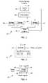
- FIG. 2is a system diagram of the storage system of the present invention.
- FIG. 3is a system diagram of a storage unit provided in the storage system of the present invention.
- FIG. 4is a system diagram of a power controller provided in the storage system of the present invention.
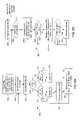
- FIG. 5 ais a flow diagram illustrating how the control unit of the archival disk-based data storage system manages the storage units with a competitive algorithm to process requests according to the present invention.
- FIG. 5 bis a flow diagram illustrating how the control unit of the storage system manages the storage units with a competitive algorithm to optimize disk lifetime and power consumption according to the present invention.
- FIG. 6 ais a flow diagram illustrating how the control unit of the storage system manages the storage units with an adaptive competitive algorithm to process requests according to the present invention.
- FIG. 6 bis a flow diagram illustrating how the control unit of the storage system manages the storage units with an adaptive competitive algorithm to optimize disk lifetime and power consumption according to the present invention.
- FIG. 7is a flow diagram illustrating how the control unit of the storage system of the present invention performs data integrity checking and migration.
- the information infrastructure 10includes a plurality of clients 12 and a server cluster 14 including one or more servers coupled together by a network 16 , a primary storage location 18 , the archival disk-based data storage system (hereafter “storage system”) 20 , and a network connection 19 coupling the primary storage location 18 and the storage system 20 .
- the clients 12can be any type of client such as but not limited to a personal computer, a “thin” client, a personal digital assistant, a web enabled appliance, or a web enabled cell phone.
- the server(s) of server cluster 14may include any type of server(s) configured as either a file server, a database server, or a combination thereof.
- the network 16can be any type of network.
- the primary storage locationmay be configured in any number of different arrangements, such as a storage array network, network attached storage, or a combination thereof.
- the primary storage location 18may be either separate or part of the server cluster 14 .
- the network connection 19can be any type of network connection, such as fiber channel, Ethernet, or SCSI.
- the storage system 20includes a control unit 22 , an interconnect 24 , a plurality of storage units (SUs) 26 , and a power controller 28 .
- the control unit 22is a standard computer such as a personal computer that interfaces with primary storage location 18 over network 19 .
- the control unit 22also operates as a master with respect to the storage units 26 and sends tasks to the storage units 26 , receives results from the storage units 26 , and controls the working modes of storage units 26 .
- the interconnect 24can be either a custom-designed interconnect or a standard local area network capable of transmitting special commands or packets to the storage units 26 .
- Each storage unit 26includes a controller 30 and one or more spindles of magnetic disks 32 .
- the storage unit 26are slaves with respect to the control unit 22 .
- the controller 30executes software that directs the storage unit 26 to shutdown or power up, change its modes between running and standby (sleep mode), and either spin up or down some or all of the magnetic disks 32 .
- the control unit 22also commands the controller 30 to periodically perform data integrity checks of the data stored on its disks 32 .
- the magnetic disks 32may assume a number of different configurations such as a Redundant Array of Independent Disks (RAID) or as individual disks in either a logical or physical arrangement.
- RAIDRedundant Array of Independent Disks
- the power controller 28includes a power input 40 for receiving power, a command input 42 for receiving an on/off command from the control unit 22 , an Input ID 44 for receiving an identity number input corresponding to one of the storage units 26 , and a number of power outputs 46 coupled to the storage units 26 respectively.
- the power controller 28can selectively provide power from input 40 to the storage units 26 through power outputs 46 respectively.
- the control unit 22is responsible for moving archived and retrieved data between the primary storage location 18 and the storage units 26 .
- the control unit 22maintains a directory of all the archived data stored in the storage system 20 .
- the directoryincludes a map of the data blocks for each of the storage units 26 in the system 20 .
- the control unit 22also includes management software that controls the physical operation of the storage units 26 and the power controller 28 . For example, the control unit 22 under the direction of the management software issues commands to determine which storage units 26 should be used, how long each storage unit 26 should run, and when a storage unit 26 should do a data integrity check.
- Power on/off commands along with an identify numberare sent to the inputs 42 and 44 of power controller 28 .
- Commands and/or packetsare sent over the interconnect 24 by the control unit 22 to instruct an individual storage unit 26 to perform the requested task.
- the controller 30 of the individual storage unit 26executes software to perform the task.
- An objective of the management software in control unit 22is to maximize the lifetime of the storage units 26 and minimize their power consumption while providing a desirable response time. Keeping the storage units 26 running all the time provides the best response time, but will consume the maximum amount of power and shorten the lifetime of disks 32 . Simply turning off the storage units 26 immediately after each request and turning them on for each request is also a poor solution in terms of response time, lifetime of disks 32 , and power consumption. This scenario provides the worst response time because the storage units 26 will be turned off as soon as the current archival or retrieval job is complete. The lifetime of the disks 32 will be shortened because most disks other than those used for laptops are engineered to handle only a limited number of starts and stops (typically less than 50,000).
- the present inventionis a competitive algorithm implemented in the management software on the control unit 22 .
- the results of using this algorithmguarantees performance to be within a factor of two of the optimal offline case.
- His the amount of time a storage unit 26 runs while waiting for another request before powering-off or entering standby.
- His set to the duration of time where the life cost and power cost of an idle spinning disk approximately equals the life cost and power cost of a disk spin up and spin down cycle.
- L and Nare variable parameters that are initialized to the spin lifetime and start-and-stop limit as defined by the disk manufacturer. These values will decrease over time as the disks consume their spin lifetime and start-and-stop limits.
- an objective of the disk-based archival storage system 20is to extend the lifetime of its disks.
- Each disktypically has a practical spin lifetime of three to five years.
- the error rate of a disktypically starts to increase significantly when the actual run time exceeds the spin lifetime of the disk.
- An important consideration thereforeis to keep track of the remaining spin lifetime of a disk or a set of disks and to use this information to determine when to spin a disk down to extend its lifetime.
- a simple algorithm to extend disk lifetimeis to spin down the disk as soon as a request is complete. Such an algorithm will preserve the remaining spin lifetime, but will typically provide an unacceptable response time following the next request.
- An improved algorithm that would generally provide better response timesis to spin the disk for a small amount of time after each request.
- the present inventionprovides an algorithm that provides both excellent response times as well as helps extend the run time and the start and stop limit of the disks.
- a diskis kept spinning after each request for the amount of time equal to the lifetime of a start and stop. Since the remaining spin lifetime and the remaining start-and-stop limit change over time, the spin time needs to be recalculated after the completion of each request.
- the algorithms of the present inventionhave the added benefit of reducing power consumption within an archival storage system 20 .
- a flow diagram 100 illustrating how the control unit 22 manages the storage units 26 with a competitive algorithm to process requests according to one embodiment of the inventionis shown.
- the control unit 22For each storage unit (SU) 26 , the control unit 22 maintains several parameters including the current threshold value of H, the remaining-spin-lifetime L, remaining number of start-and-stops N, and the time-stamp of the last-request T (step 102 ).
- the control unit 22receives either an archival or retrieval request (step 104 ), it first allocates a storage unit 26 for an archival request or finds the appropriate storage unit 26 for a retrieval request using the directory of all the archived data stored in the storage system 20 (step 106 ).
- control unit 22determines if the storage unit 26 is on (diamond 108 ). If the storage unit 26 is off or in standby mode (diamond 110 ), the control unit 22 issues commands to either power on or wake up the storage unit 26 (step 110 ). When the storage unit 26 is ready, the request will be sent (step 112 ) to that storage unit 26 . If the storage unit 26 is already on (diamond 108 ), the request is sent immediately to that storage unit 26 (step 112 ). After the request is processes by the storage unit 26 , it is reset and the values of SU.L and SU.T are all updated.
- a flow diagram 200illustrating how the control unit 22 manages the storage units 26 with a constant competitive algorithm to optimize disk lifetime and power consumption according to one embodiment of the invention is shown.
- the control unit 22checks the status of all the running storage units 26 every k seconds (step 202 ). During this check, the control unit 22 sequences through storage units 26 , one at a time, and identifies which are running (step 204 ). For each running storage unit 26 , the control unit 22 computes an individual threshold SU.H using equation (1) as defined above (step 206 ). The control unit 22 then checks to determine if the threshold SU. H for each running storage unit 26 is greater than the elapsed time since the previous request Time( ) ⁇ SU.T (step 208 ).
- controlis returned to step 204 .
- the control unit 22will turn off that storage unit 26 or issue a command to place it in standby mode.
- the values for SU.L and SU.Nare also updated (step 210 ).
- the remaining spin lifetime SU.Lis calculated as described above.
- the number of remaining start-and-stops SU.Nis calculated by decrementing the previous value of SU.N by one.
- decision diamond 212it is determined if the remaining lifetime SU.L and the remaining number of stall and stops SU.N are too small as determined by the manufacturer of the disks 32 . If no, control is returned to step 204 .
- a warningis generated (step 214 ) indicating that the storage unit 26 or at least the disks 32 should be replaced. After all the storage units have been checked, control is returned to box 202 and K seconds elapses before the above steps are repeated.
- FIG. 6Aa flow diagram 300 illustrating how the control unit 22 may manage the storage units 26 with an adaptive competitive algorithm to process requests according to another embodiment of the present invention is shown.
- an adaptive algorithmis used that dynamically adjusts the value of H for each storage unit 26 based on the frequency and timing of requests.
- the adaptive algorithmis based on the assumption that there is a high probability that the wait time for the next request will exceed the time equivalent of a spin up and down cycle if the previous wait time for a request also exceeded the spin up and down cycle time. In situations where request arrivals tend to have temporal locality, this algorithm will achieve better results than the previous competitive algorithm.
- the flow chart 300is similar to flow chart 100 of FIG. 5 a . Steps 302 – 308 are identical to those of steps 102 – 108 of FIG. 5 a respectively and therefore are not described in detail herein.
- HminSU.H
- HminMmax/10.
- the current value of SU.His greater than Hmin, then the current value is decremented (step 312 ) before the storage unit 26 is turned on or woken up (step 314 ). If the current value of SU.H is less than Hmin, then the current value is not decremented and the storage unit 26 is turned on or woken up (step 314 ). Thereafter the request is sent to the storage unit 26 (step 316 ). On the other hand, if the storage unit 26 is on, then the current value of SU.H is compared to Hmax (step 318 ). If the current value is less than Hmax, the current value is incremented (step 320 ) and then the request is sent to the storage unit 26 .
- step 316the values of SU.L and SU.T are updated in a similar manner as described above (step 316 ).
- SU.His adjusted between Hmax and Hmin in order to guarantee that the performance is within a factor of two of the optimal offline case.
- FIG. 6Bis a flow diagram 300 illustrating how a control unit of the archival disk-based data storage system manages the storage units with an adaptive competitive algorithm to optimize disk lifetime and power consumption according to the present invention.
- FIG. 6Bis identical to 5 B except in step 406 , Hmax and Hmin are recomputed. Thus the value of SU.H remains within the limits of these two thresholds. Otherwise the remainder of the flow chart for 408 – 414 are identical to 208 – 214 of FIG. 5B .
- the present inventionthus describes several approaches to extend the lifetime of disk storage in a storage unit 26 .
- the first approachkeeps track of and uses the remaining spin life of a storage unit 26 to determine when to spin up and down to extend the lifetime of the disk(s) in the storage unit 26 .
- the second approachis to use the remaining spin life and the remaining start-and-stop limit of a storage unit 26 to determine when to spin up and down to extend the lifetime of the disk(s) in the storage unit 26 .
- the thirdis to use the life cost and power cost as a measure to combine spin life, start-and-stop limit, and power consumption, in order to determine when to spin up and down the storage unit 26 in order to improve both the lifetime and the power consumption of a storage unit 26 .
- This applicationdescribed two algorithms using the third approach: a competitive algorithm and an adaptive competitive algorithm. Both algorithms have the property that their results are within a factor of two of the optimal offline case.
- the storage system 20ideally needs to maintain the integrity of its data for a long period of time. This is challenging for two reasons. Disks 32 often have undetectable errors.
- the error rate of current disk drive technologyis typically 1 in 10 13 or 10 14 .
- detectable errorscan be corrected.
- detectable errorscan be detected only when accessing data. Thus, there may be intervening catastrophic disk failures that can not be corrected even if they are detectable.
- each storage unit 26uses an algorithm to compute and store an error correction code (ECC) for each data block stored on its disks 32 .
- ECCerror correction code
- the storage unitre-computes the ECC and compares it with the code stored with the data. If they are identical, it is assumed there are no errors. On the other hand if they are not identical, the controller will re-compute the ECC value yet again. If the ECC values are still different, the storage unit 26 invokes correction code to correct the error and the data is stored in a new location. Whenever data is migrated (or scrubbed) to a new location, the directory of all the archived data stored in the storage system 20 maintained by the control unit 22 is updated.
- the data integrity checkprocesses one object at a time (step 502 ).
- the algorithmsorts the object's data blocks by location (step 504 ) and then checks one data block at a time (step 506 ). For each block, integrity errors are identified by calculating the ECC code (step 508 ). If there is no error, the data block is rewritten to the same location (step 520 ). If there are errors, then the algorithm checks to see whether the errors are correctable (step 510 ). If errors are not correctable, it will log the errors and go to check the next block ( 522 ).
- step 512For correctable errors, it tries to find a new location for data scrubbing (step 512 ). If a new location is available on the same storage unit 26 , the data be scrubbed and the directory is updated. On the other hand if it a new location can not be found, the storage unit 26 informs the control unit 22 that this object needs to be migrate to another storage unit 26 (step 524 ). If a new location is found, the data is migrated to the new storage unit 26 and the directory in the control unit 22 is updated before the next block is checked (step 514 ). When the data integrity check process completes, the control unit 22 is notified of the completion (step 516 ) and then shuts down the storage unit 26 or puts the unit into standby mode (step 518 ).
- the storage system 20can be designed without a power controller 28 .
- the control unit 22would not be capable powering off the storage units 26 . Power would be conserved only by placing the storage units into standby mode. Typically the decision to either power off or place a disk into standby mode is a trade off between lower power consumption versus response time. If power consumption is more important than response time, the disks 32 should be powered off. If response time is more important, then the disks should be placed into a standby mode.
- the controller 30can be a computer used to control the storage unit 26 . Therefore, the described embodiments should be taken as illustrative and not restrictive, and the invention should not be limited to the details given herein but should be defined by the following claims and their full scope of equivalents.
Landscapes
- Engineering & Computer Science (AREA)
- Theoretical Computer Science (AREA)
- Physics & Mathematics (AREA)
- General Engineering & Computer Science (AREA)
- General Physics & Mathematics (AREA)
- Human Computer Interaction (AREA)
- Quality & Reliability (AREA)
- Power Sources (AREA)
Abstract
Description
- where:
- CSU: the cost of the storage unit
- CW: the cost per watt
- L: the spin lifetime
- N: the total number of start-and-stops
- TUp: the time taken to spin up
- WRW: the number of watts consumed for read or write operations, and
- WUp: the number of watts consumed for a spin up.
- where:
where S is the size of the storage unit and BW is the bandwidth of checking data integrity.
Claims (50)
Priority Applications (2)
| Application Number | Priority Date | Filing Date | Title |
|---|---|---|---|
| US10/061,081US7007141B2 (en) | 2001-01-30 | 2002-01-29 | Archival data storage system and method |
| PCT/US2003/002785WO2003065360A1 (en) | 2002-01-29 | 2003-01-28 | Disk-based archival data storage system and method |
Applications Claiming Priority (2)
| Application Number | Priority Date | Filing Date | Title |
|---|---|---|---|
| US26518001P | 2001-01-30 | 2001-01-30 | |
| US10/061,081US7007141B2 (en) | 2001-01-30 | 2002-01-29 | Archival data storage system and method |
Publications (2)
| Publication Number | Publication Date |
|---|---|
| US20020144057A1 US20020144057A1 (en) | 2002-10-03 |
| US7007141B2true US7007141B2 (en) | 2006-02-28 |
Family
ID=27658365
Family Applications (1)
| Application Number | Title | Priority Date | Filing Date |
|---|---|---|---|
| US10/061,081Expired - LifetimeUS7007141B2 (en) | 2001-01-30 | 2002-01-29 | Archival data storage system and method |
Country Status (2)
| Country | Link |
|---|---|
| US (1) | US7007141B2 (en) |
| WO (1) | WO2003065360A1 (en) |
Cited By (20)
| Publication number | Priority date | Publication date | Assignee | Title |
|---|---|---|---|---|
| US20050138223A1 (en)* | 2003-12-17 | 2005-06-23 | International Business Machines Corp. | Autonomic hardware-level storage device data integrity checking |
| US20060107099A1 (en)* | 2004-10-28 | 2006-05-18 | Nec Laboratories America, Inc. | System and Method for Redundant Storage with Improved Energy Consumption |
| US20060224915A1 (en)* | 2005-03-29 | 2006-10-05 | Fujitsu Limited | Apparatus, method, and computer product for executing program |
| US20070079156A1 (en)* | 2005-09-30 | 2007-04-05 | Kazuhisa Fujimoto | Computer apparatus, storage apparatus, system management apparatus, and hard disk unit power supply controlling method |
| US20070180211A1 (en)* | 2005-11-21 | 2007-08-02 | Nobumitsu Takaoka | Computer system and method of reproducing data for the system |
| US20070220316A1 (en)* | 2002-09-03 | 2007-09-20 | Copan Systems, Inc. | Method and Apparatus for Power-Efficient High-Capacity Scalable Storage System |
| US20070234077A1 (en)* | 2006-03-31 | 2007-10-04 | Rothman Michael A | Reducing power consumption by load imbalancing |
| US20070244920A1 (en)* | 2003-12-12 | 2007-10-18 | Sudarshan Palliyil | Hash-Based Access To Resources in a Data Processing Network |
| US20080034268A1 (en)* | 2006-04-07 | 2008-02-07 | Brian Dodd | Data compression and storage techniques |
| US20080208935A1 (en)* | 2003-12-12 | 2008-08-28 | International Business Machines Corporation | Computer Program Product and Computer System for Controlling Performance of Operations within a Data Processing System or Networks |
| US20090198886A1 (en)* | 2008-02-05 | 2009-08-06 | International Business Machines Corporation | Power Conservation in a Composite Array of Data Storage Devices |
| US20100122050A1 (en)* | 2008-11-13 | 2010-05-13 | International Business Machines Corporation | Virtual storage migration technique to minimize spinning disks |
| US20100157463A1 (en)* | 2008-12-18 | 2010-06-24 | Arizono Yukiko | Disk drive spin control |
| US20100174878A1 (en)* | 2009-01-06 | 2010-07-08 | Crawford Communications | Systems and Methods for Monitoring Archive Storage Condition and Preventing the Loss of Archived Data |
| US20100281276A1 (en)* | 2009-04-29 | 2010-11-04 | Micro-Star Internationa'l Co., Ltd. | Computer system with power source control and power source control method |
| US20110167220A1 (en)* | 2003-02-17 | 2011-07-07 | Hitachi, Ltd. | Storage system for holding a remaining available lifetime of a logical storage region |
| US8099401B1 (en) | 2007-07-18 | 2012-01-17 | Emc Corporation | Efficiently indexing and searching similar data |
| US20120246432A1 (en)* | 2011-03-21 | 2012-09-27 | Hadley Ted A | Methods, systems, and apparatus to prevent memory imprinting |
| US8832045B2 (en) | 2006-04-07 | 2014-09-09 | Data Storage Group, Inc. | Data compression and storage techniques |
| US20210090762A1 (en)* | 2018-10-11 | 2021-03-25 | International Business Machines Corporation | Hybrid cable assembly |
Families Citing this family (85)
| Publication number | Priority date | Publication date | Assignee | Title |
|---|---|---|---|---|
| JP4325817B2 (en)* | 1999-04-05 | 2009-09-02 | 株式会社日立製作所 | Disk array device |
| US6859399B1 (en) | 2000-05-17 | 2005-02-22 | Marvell International, Ltd. | Memory architecture and system and multiport interface protocol |
| EP2017901A1 (en)* | 2001-09-03 | 2009-01-21 | Panasonic Corporation | Semiconductor light emitting device, light emitting apparatus and production method for semiconductor light emitting DEV |
| US7454529B2 (en)* | 2002-08-02 | 2008-11-18 | Netapp, Inc. | Protectable data storage system and a method of protecting and/or managing a data storage system |
| US7882081B2 (en) | 2002-08-30 | 2011-02-01 | Netapp, Inc. | Optimized disk repository for the storage and retrieval of mostly sequential data |
| US7437387B2 (en) | 2002-08-30 | 2008-10-14 | Netapp, Inc. | Method and system for providing a file system overlay |
| US7035972B2 (en)* | 2002-09-03 | 2006-04-25 | Copan Systems, Inc. | Method and apparatus for power-efficient high-capacity scalable storage system |
| US7210004B2 (en)* | 2003-06-26 | 2007-04-24 | Copan Systems | Method and system for background processing of data in a storage system |
| WO2004025628A2 (en) | 2002-09-12 | 2004-03-25 | Copan Systems, Inc. | Method and apparatus for power-efficient high-capacity scalable storage system |
| US8024172B2 (en) | 2002-12-09 | 2011-09-20 | Netapp, Inc. | Method and system for emulating tape libraries |
| US7567993B2 (en) | 2002-12-09 | 2009-07-28 | Netapp, Inc. | Method and system for creating and using removable disk based copies of backup data |
| US6973369B2 (en) | 2003-03-12 | 2005-12-06 | Alacritus, Inc. | System and method for virtual vaulting |
| JP4372450B2 (en)* | 2003-05-07 | 2009-11-25 | 株式会社日立製作所 | Storage system control method, storage system, and storage apparatus |
| US7437492B2 (en) | 2003-05-14 | 2008-10-14 | Netapp, Inc | Method and system for data compression and compression estimation in a virtual tape library environment |
| JP2004348464A (en) | 2003-05-22 | 2004-12-09 | Hitachi Ltd | Storage device and communication signal shaping circuit |
| JP4060235B2 (en) | 2003-05-22 | 2008-03-12 | 株式会社日立製作所 | Disk array device and disk array device control method |
| US7434097B2 (en)* | 2003-06-05 | 2008-10-07 | Copan System, Inc. | Method and apparatus for efficient fault-tolerant disk drive replacement in raid storage systems |
| JP4433372B2 (en) | 2003-06-18 | 2010-03-17 | 株式会社日立製作所 | Data access system and method |
| US7330931B2 (en)* | 2003-06-26 | 2008-02-12 | Copan Systems, Inc. | Method and system for accessing auxiliary data in power-efficient high-capacity scalable storage system |
| US20050210304A1 (en)* | 2003-06-26 | 2005-09-22 | Copan Systems | Method and apparatus for power-efficient high-capacity scalable storage system |
| US7484050B2 (en)* | 2003-09-08 | 2009-01-27 | Copan Systems Inc. | High-density storage systems using hierarchical interconnect |
| US7373559B2 (en)* | 2003-09-11 | 2008-05-13 | Copan Systems, Inc. | Method and system for proactive drive replacement for high availability storage systems |
| US20060090098A1 (en)* | 2003-09-11 | 2006-04-27 | Copan Systems, Inc. | Proactive data reliability in a power-managed storage system |
| JP4486348B2 (en)* | 2003-11-26 | 2010-06-23 | 株式会社日立製作所 | Disk array that suppresses drive operating time |
| JP4156499B2 (en) | 2003-11-28 | 2008-09-24 | 株式会社日立製作所 | Disk array device |
| US7475427B2 (en)* | 2003-12-12 | 2009-01-06 | International Business Machines Corporation | Apparatus, methods and computer programs for identifying or managing vulnerabilities within a data processing network |
| JP4497918B2 (en) | 2003-12-25 | 2010-07-07 | 株式会社日立製作所 | Storage system |
| JP2005190036A (en)* | 2003-12-25 | 2005-07-14 | Hitachi Ltd | Storage control device and control method of storage control device |
| JP4463042B2 (en)* | 2003-12-26 | 2010-05-12 | 株式会社日立製作所 | Storage system having volume dynamic allocation function |
| JP4518541B2 (en)* | 2004-01-16 | 2010-08-04 | 株式会社日立製作所 | Disk array device and disk array device control method |
| US7426617B2 (en) | 2004-02-04 | 2008-09-16 | Network Appliance, Inc. | Method and system for synchronizing volumes in a continuous data protection system |
| US7406488B2 (en) | 2004-02-04 | 2008-07-29 | Netapp | Method and system for maintaining data in a continuous data protection system |
| JP4634049B2 (en) | 2004-02-04 | 2011-02-16 | 株式会社日立製作所 | Error notification control in disk array system |
| US7720817B2 (en) | 2004-02-04 | 2010-05-18 | Netapp, Inc. | Method and system for browsing objects on a protected volume in a continuous data protection system |
| US7783606B2 (en) | 2004-02-04 | 2010-08-24 | Netapp, Inc. | Method and system for remote data recovery |
| US7559088B2 (en) | 2004-02-04 | 2009-07-07 | Netapp, Inc. | Method and apparatus for deleting data upon expiration |
| US7904679B2 (en) | 2004-02-04 | 2011-03-08 | Netapp, Inc. | Method and apparatus for managing backup data |
| US7490103B2 (en) | 2004-02-04 | 2009-02-10 | Netapp, Inc. | Method and system for backing up data |
| US7325159B2 (en) | 2004-02-04 | 2008-01-29 | Network Appliance, Inc. | Method and system for data recovery in a continuous data protection system |
| US7315965B2 (en) | 2004-02-04 | 2008-01-01 | Network Appliance, Inc. | Method and system for storing data using a continuous data protection system |
| US7295395B2 (en) | 2004-03-12 | 2007-11-13 | Seagate Technology Llc | Sensing a prior transducer position by a motion pattern |
| US8028135B1 (en) | 2004-09-01 | 2011-09-27 | Netapp, Inc. | Method and apparatus for maintaining compliant storage |
| US7434090B2 (en)* | 2004-09-30 | 2008-10-07 | Copan System, Inc. | Method and apparatus for just in time RAID spare drive pool management |
| EP1797510A2 (en) | 2004-10-06 | 2007-06-20 | Permabit, Inc. | A storage system for randomly named blocks of data |
| US7526620B1 (en) | 2004-12-14 | 2009-04-28 | Netapp, Inc. | Disk sanitization in an active file system |
| US7558839B1 (en) | 2004-12-14 | 2009-07-07 | Netapp, Inc. | Read-after-write verification for improved write-once-read-many data storage |
| US7774610B2 (en) | 2004-12-14 | 2010-08-10 | Netapp, Inc. | Method and apparatus for verifiably migrating WORM data |
| US7581118B2 (en) | 2004-12-14 | 2009-08-25 | Netapp, Inc. | Disk sanitization using encryption |
| US7380088B2 (en)* | 2005-02-04 | 2008-05-27 | Dot Hill Systems Corp. | Storage device method and apparatus |
| JP2006221335A (en)* | 2005-02-09 | 2006-08-24 | Toshiba Corp | Information recording device |
| JP2006236019A (en)* | 2005-02-25 | 2006-09-07 | Hitachi Ltd | Switching method of data copy method |
| JP4824374B2 (en)* | 2005-09-20 | 2011-11-30 | 株式会社日立製作所 | System that controls the rotation of the disc |
| US20070079086A1 (en)* | 2005-09-29 | 2007-04-05 | Copan Systems, Inc. | System for archival storage of data |
| US7401198B2 (en) | 2005-10-06 | 2008-07-15 | Netapp | Maximizing storage system throughput by measuring system performance metrics |
| US7752401B2 (en) | 2006-01-25 | 2010-07-06 | Netapp, Inc. | Method and apparatus to automatically commit files to WORM status |
| JP2007213721A (en)* | 2006-02-10 | 2007-08-23 | Hitachi Ltd | Storage system and control method thereof |
| US20080065703A1 (en)* | 2006-02-22 | 2008-03-13 | Copan Systems, Inc. | Configurable views of archived data storage |
| JP2007241334A (en)* | 2006-03-03 | 2007-09-20 | Hitachi Ltd | Storage system and control method thereof |
| JP4834434B2 (en)* | 2006-03-17 | 2011-12-14 | 富士通株式会社 | Power supply control method for storage device |
| US7650533B1 (en) | 2006-04-20 | 2010-01-19 | Netapp, Inc. | Method and system for performing a restoration in a continuous data protection system |
| JP4984689B2 (en)* | 2006-07-04 | 2012-07-25 | 日本電気株式会社 | Disk array control device, method, and program |
| GB0616375D0 (en)* | 2006-08-17 | 2006-09-27 | Ibm | An apparatus for facilitating disaster recovery |
| JP4919752B2 (en)* | 2006-09-29 | 2012-04-18 | 株式会社日立製作所 | Storage controller |
| US20090161243A1 (en)* | 2007-12-21 | 2009-06-25 | Ratnesh Sharma | Monitoring Disk Drives To Predict Failure |
| US8140754B2 (en)* | 2008-01-03 | 2012-03-20 | Hitachi, Ltd. | Methods and apparatus for managing HDD's spin-down and spin-up in tiered storage systems |
| US8914340B2 (en)* | 2008-02-06 | 2014-12-16 | International Business Machines Corporation | Apparatus, system, and method for relocating storage pool hot spots |
| US8423739B2 (en)* | 2008-02-06 | 2013-04-16 | International Business Machines Corporation | Apparatus, system, and method for relocating logical array hot spots |
| JP5328445B2 (en)* | 2008-05-02 | 2013-10-30 | キヤノン株式会社 | Information processing apparatus and information processing apparatus control method |
| JP4988653B2 (en)* | 2008-06-13 | 2012-08-01 | 株式会社日立製作所 | Disk array recording apparatus and recording control method therefor |
| WO2010109675A1 (en)* | 2009-03-24 | 2010-09-30 | Hitachi, Ltd. | Storage system |
| US8122217B2 (en) | 2009-05-06 | 2012-02-21 | International Business Machines Corporation | Method of a full coverage low power mode for storage systems storing replicated data items |
| US8627130B2 (en)* | 2009-10-08 | 2014-01-07 | Bridgette, Inc. | Power saving archive system |
| KR20120096562A (en)* | 2010-01-21 | 2012-08-30 | 후지쯔 가부시끼가이샤 | Information processing apparatus, drive control program and drive control method |
| US8677162B2 (en) | 2010-12-07 | 2014-03-18 | International Business Machines Corporation | Reliability-aware disk power management |
| US9069707B1 (en) | 2011-11-03 | 2015-06-30 | Permabit Technology Corp. | Indexing deduplicated data |
| US20140181061A1 (en)* | 2012-12-21 | 2014-06-26 | Hong Jiang | Data distribution in a cloud computing system |
| US9953042B1 (en) | 2013-03-01 | 2018-04-24 | Red Hat, Inc. | Managing a deduplicated data index |
| US9331609B1 (en)* | 2013-10-29 | 2016-05-03 | Rossie Owen Terry | Electrical motors and methods thereof having reduced electromagnetic emissions |
| WO2015175720A1 (en)* | 2014-05-13 | 2015-11-19 | Netapp, Inc. | Storage operations utilizing a multiple-data-storage-devices cartridge |
| US10289326B2 (en) | 2015-09-14 | 2019-05-14 | HGST Netherlands, B.V. | Optimized data layout for object store system |
| US10073625B2 (en)* | 2016-01-06 | 2018-09-11 | HGST Netherlands B.V. | Variable-RPM hard disk drive control |
| JP6768425B2 (en) | 2016-09-08 | 2020-10-14 | キヤノン株式会社 | Information processing equipment, its control method, and programs |
| JP2018078434A (en)* | 2016-11-09 | 2018-05-17 | 富士通株式会社 | Transmission device, information processing system, and transmission method |
| JP7045818B2 (en)* | 2017-08-09 | 2022-04-01 | キヤノン株式会社 | Image processing device and its control method |
| CN114356514B (en)* | 2021-12-03 | 2024-11-05 | 阿里巴巴(中国)有限公司 | Data processing task scheduling method, device, storage medium and electronic device |
Citations (33)
| Publication number | Priority date | Publication date | Assignee | Title |
|---|---|---|---|---|
| US3689891A (en)* | 1970-11-02 | 1972-09-05 | Texas Instruments Inc | Memory system |
| US4084231A (en) | 1975-12-18 | 1978-04-11 | International Business Machines Corporation | System for facilitating the copying back of data in disc and tape units of a memory hierarchial system |
| US4145739A (en) | 1977-06-20 | 1979-03-20 | Wang Laboratories, Inc. | Distributed data processing system |
| US4532802A (en) | 1984-05-31 | 1985-08-06 | International Business Machines Corporation | Apparatus for analyzing the interface between a recording disk and a read-write head |
| US4933785A (en) | 1988-03-01 | 1990-06-12 | Prairietek Corporation | Disk drive apparatus using dynamic loading/unloading |
| US4980896A (en) | 1986-04-15 | 1990-12-25 | Hampshire Instruments, Inc. | X-ray lithography system |
| US4987502A (en) | 1986-10-06 | 1991-01-22 | Eastman Kodak Company | Anti-wear disk drive system |
| US5124987A (en)* | 1990-04-16 | 1992-06-23 | Storage Technology Corporation | Logical track write scheduling system for a parallel disk drive array data storage subsystem |
| US5134602A (en)* | 1990-09-27 | 1992-07-28 | International Business Machines Corporation | Calibrating optical disk recorders to some parameters during disk spin up while deferring calibration of other parameters |
| US5155835A (en)* | 1990-11-19 | 1992-10-13 | Storage Technology Corporation | Multilevel, hierarchical, dynamically mapped data storage subsystem |
| US5197055A (en)* | 1990-05-21 | 1993-03-23 | International Business Machines Corporation | Idle demount in an automated storage library |
| US5210866A (en)* | 1990-09-12 | 1993-05-11 | Storage Technology Corporation | Incremental disk backup system for a dynamically mapped data storage subsystem |
| US5345347A (en) | 1992-02-18 | 1994-09-06 | Western Digital Corporation | Disk drive with reduced power modes |
| US5402200A (en) | 1988-02-04 | 1995-03-28 | Conner Peripherals, Inc. | Low-power hard disk drive system architecture |
| US5423046A (en) | 1992-12-17 | 1995-06-06 | International Business Machines Corporation | High capacity data storage system using disk array |
| US5442608A (en) | 1990-07-19 | 1995-08-15 | Mitsubishi Electric Corp | Disk apparatus having a power consumption reducing mechanism |
| US5452277A (en) | 1993-12-30 | 1995-09-19 | International Business Machines Corporation | Adaptive system for optimizing disk drive power consumption |
| US5469553A (en) | 1992-04-16 | 1995-11-21 | Quantum Corporation | Event driven power reducing software state machine |
| US5481733A (en) | 1994-06-15 | 1996-01-02 | Panasonic Technologies, Inc. | Method for managing the power distributed to a disk drive in a laptop computer |
| US5517649A (en) | 1994-04-19 | 1996-05-14 | Maxtor Corporation | Adaptive power management for hard disk drives |
| US5682273A (en) | 1995-06-30 | 1997-10-28 | International Business Machines Corporation | Disk drive for portable computer with adaptive demand-driven power management |
| US5745458A (en)* | 1994-04-05 | 1998-04-28 | Hewlett-Packard Company | Overlapped spin-up process for optical disk drive |
| US5774292A (en) | 1995-04-13 | 1998-06-30 | International Business Machines Corporation | Disk drive power management system and method |
| US5784610A (en)* | 1994-11-21 | 1998-07-21 | International Business Machines Corporation | Check image distribution and processing system and method |
| US5821924A (en) | 1992-09-04 | 1998-10-13 | Elonex I.P. Holdings, Ltd. | Computer peripherals low-power-consumption standby system |
| US5870264A (en) | 1993-09-06 | 1999-02-09 | Restle; Wilfried | Method and arrangement for significantly increasing the lifetime of magnetic disk storage devices |
| US5954820A (en) | 1997-09-26 | 1999-09-21 | International Business Machines Corporation | Portable computer with adaptive demand-driven power management |
| US5961613A (en) | 1995-06-07 | 1999-10-05 | Ast Research, Inc. | Disk power manager for network servers |
| US6115509A (en)* | 1994-03-10 | 2000-09-05 | International Business Machines Corp | High volume document image archive system and method |
| US6430005B1 (en)* | 1991-10-18 | 2002-08-06 | Syquest Technology, Inc. | Removable cartridge disk drive with a receiver for receiving a cartridge housing a hard disk |
| US6470071B1 (en)* | 2001-01-31 | 2002-10-22 | General Electric Company | Real time data acquisition system including decoupled host computer |
| US6600703B1 (en)* | 2001-04-26 | 2003-07-29 | International Business Machines Corporation | Magazine for a plurality of removable hard disk drives |
| US6732125B1 (en)* | 2000-09-08 | 2004-05-04 | Storage Technology Corporation | Self archiving log structured volume with intrinsic data protection |
Family Cites Families (2)
| Publication number | Priority date | Publication date | Assignee | Title |
|---|---|---|---|---|
| FR2642008B1 (en)* | 1989-01-26 | 1992-01-03 | Boitabloc | WRITE SUPPORT |
| US5469533A (en)* | 1992-07-10 | 1995-11-21 | Microsoft Corporation | Resource-oriented printer system and method of operation |
- 2002
- 2002-01-29USUS10/061,081patent/US7007141B2/ennot_activeExpired - Lifetime
- 2003
- 2003-01-28WOPCT/US2003/002785patent/WO2003065360A1/ennot_activeApplication Discontinuation
Patent Citations (35)
| Publication number | Priority date | Publication date | Assignee | Title |
|---|---|---|---|---|
| US3689891A (en)* | 1970-11-02 | 1972-09-05 | Texas Instruments Inc | Memory system |
| US4084231A (en) | 1975-12-18 | 1978-04-11 | International Business Machines Corporation | System for facilitating the copying back of data in disc and tape units of a memory hierarchial system |
| US4145739A (en) | 1977-06-20 | 1979-03-20 | Wang Laboratories, Inc. | Distributed data processing system |
| US4532802A (en) | 1984-05-31 | 1985-08-06 | International Business Machines Corporation | Apparatus for analyzing the interface between a recording disk and a read-write head |
| US4980896A (en) | 1986-04-15 | 1990-12-25 | Hampshire Instruments, Inc. | X-ray lithography system |
| US4987502A (en) | 1986-10-06 | 1991-01-22 | Eastman Kodak Company | Anti-wear disk drive system |
| US5402200A (en) | 1988-02-04 | 1995-03-28 | Conner Peripherals, Inc. | Low-power hard disk drive system architecture |
| US4933785A (en) | 1988-03-01 | 1990-06-12 | Prairietek Corporation | Disk drive apparatus using dynamic loading/unloading |
| US5124987A (en)* | 1990-04-16 | 1992-06-23 | Storage Technology Corporation | Logical track write scheduling system for a parallel disk drive array data storage subsystem |
| US5197055A (en)* | 1990-05-21 | 1993-03-23 | International Business Machines Corporation | Idle demount in an automated storage library |
| US5442608A (en) | 1990-07-19 | 1995-08-15 | Mitsubishi Electric Corp | Disk apparatus having a power consumption reducing mechanism |
| US5210866A (en)* | 1990-09-12 | 1993-05-11 | Storage Technology Corporation | Incremental disk backup system for a dynamically mapped data storage subsystem |
| US5134602A (en)* | 1990-09-27 | 1992-07-28 | International Business Machines Corporation | Calibrating optical disk recorders to some parameters during disk spin up while deferring calibration of other parameters |
| US5155835A (en)* | 1990-11-19 | 1992-10-13 | Storage Technology Corporation | Multilevel, hierarchical, dynamically mapped data storage subsystem |
| US6430005B1 (en)* | 1991-10-18 | 2002-08-06 | Syquest Technology, Inc. | Removable cartridge disk drive with a receiver for receiving a cartridge housing a hard disk |
| US5345347A (en) | 1992-02-18 | 1994-09-06 | Western Digital Corporation | Disk drive with reduced power modes |
| US5469553A (en) | 1992-04-16 | 1995-11-21 | Quantum Corporation | Event driven power reducing software state machine |
| US5821924A (en) | 1992-09-04 | 1998-10-13 | Elonex I.P. Holdings, Ltd. | Computer peripherals low-power-consumption standby system |
| US5423046A (en) | 1992-12-17 | 1995-06-06 | International Business Machines Corporation | High capacity data storage system using disk array |
| US5900007A (en) | 1992-12-17 | 1999-05-04 | International Business Machines Corporation | Data storage disk array having a constraint function for spatially dispersing disk files in the disk array |
| US5870264A (en) | 1993-09-06 | 1999-02-09 | Restle; Wilfried | Method and arrangement for significantly increasing the lifetime of magnetic disk storage devices |
| US5452277A (en) | 1993-12-30 | 1995-09-19 | International Business Machines Corporation | Adaptive system for optimizing disk drive power consumption |
| US6115509A (en)* | 1994-03-10 | 2000-09-05 | International Business Machines Corp | High volume document image archive system and method |
| US5745458A (en)* | 1994-04-05 | 1998-04-28 | Hewlett-Packard Company | Overlapped spin-up process for optical disk drive |
| US5517649A (en) | 1994-04-19 | 1996-05-14 | Maxtor Corporation | Adaptive power management for hard disk drives |
| US5493670A (en) | 1994-06-15 | 1996-02-20 | Panasonic Technologies, Inc. | Adaptive disk spin-down method for managing the power distributed to a disk drive in a laptop computer |
| US5481733A (en) | 1994-06-15 | 1996-01-02 | Panasonic Technologies, Inc. | Method for managing the power distributed to a disk drive in a laptop computer |
| US5784610A (en)* | 1994-11-21 | 1998-07-21 | International Business Machines Corporation | Check image distribution and processing system and method |
| US5774292A (en) | 1995-04-13 | 1998-06-30 | International Business Machines Corporation | Disk drive power management system and method |
| US5961613A (en) | 1995-06-07 | 1999-10-05 | Ast Research, Inc. | Disk power manager for network servers |
| US5682273A (en) | 1995-06-30 | 1997-10-28 | International Business Machines Corporation | Disk drive for portable computer with adaptive demand-driven power management |
| US5954820A (en) | 1997-09-26 | 1999-09-21 | International Business Machines Corporation | Portable computer with adaptive demand-driven power management |
| US6732125B1 (en)* | 2000-09-08 | 2004-05-04 | Storage Technology Corporation | Self archiving log structured volume with intrinsic data protection |
| US6470071B1 (en)* | 2001-01-31 | 2002-10-22 | General Electric Company | Real time data acquisition system including decoupled host computer |
| US6600703B1 (en)* | 2001-04-26 | 2003-07-29 | International Business Machines Corporation | Magazine for a plurality of removable hard disk drives |
Cited By (38)
| Publication number | Priority date | Publication date | Assignee | Title |
|---|---|---|---|---|
| US20070220316A1 (en)* | 2002-09-03 | 2007-09-20 | Copan Systems, Inc. | Method and Apparatus for Power-Efficient High-Capacity Scalable Storage System |
| US20110167220A1 (en)* | 2003-02-17 | 2011-07-07 | Hitachi, Ltd. | Storage system for holding a remaining available lifetime of a logical storage region |
| US8024306B2 (en) | 2003-12-12 | 2011-09-20 | International Business Machines Corporation | Hash-based access to resources in a data processing network |
| US20070244920A1 (en)* | 2003-12-12 | 2007-10-18 | Sudarshan Palliyil | Hash-Based Access To Resources in a Data Processing Network |
| US20080208935A1 (en)* | 2003-12-12 | 2008-08-28 | International Business Machines Corporation | Computer Program Product and Computer System for Controlling Performance of Operations within a Data Processing System or Networks |
| US7689835B2 (en)* | 2003-12-12 | 2010-03-30 | International Business Machines Corporation | Computer program product and computer system for controlling performance of operations within a data processing system or networks |
| US20050138223A1 (en)* | 2003-12-17 | 2005-06-23 | International Business Machines Corp. | Autonomic hardware-level storage device data integrity checking |
| US7600051B2 (en)* | 2003-12-17 | 2009-10-06 | International Business Machines Corporation | Autonomic hardware-level storage device data integrity checking |
| US7516346B2 (en)* | 2004-10-28 | 2009-04-07 | Nec Laboratories America, Inc. | System and method for dynamically changing the power mode of storage disks based on redundancy and system load |
| US20060107099A1 (en)* | 2004-10-28 | 2006-05-18 | Nec Laboratories America, Inc. | System and Method for Redundant Storage with Improved Energy Consumption |
| US20060224915A1 (en)* | 2005-03-29 | 2006-10-05 | Fujitsu Limited | Apparatus, method, and computer product for executing program |
| US7761737B2 (en)* | 2005-03-29 | 2010-07-20 | Fujitsu Limited | Apparatus, method, and computer product for executing program |
| US20090077392A1 (en)* | 2005-09-30 | 2009-03-19 | Kazuhisa Fujimoto | Computer apparatus, storage apparatus, system management apparatus, and hard disk unit power supply controlling method |
| US20070079156A1 (en)* | 2005-09-30 | 2007-04-05 | Kazuhisa Fujimoto | Computer apparatus, storage apparatus, system management apparatus, and hard disk unit power supply controlling method |
| US7640443B2 (en) | 2005-09-30 | 2009-12-29 | Hitachi, Ltd. | Computer apparatus, storage apparatus, system management apparatus, and hard disk unit power supply controlling method |
| US7426646B2 (en)* | 2005-09-30 | 2008-09-16 | Hitachi, Ltd. | Computer apparatus, storage apparatus, system management apparatus, and hard disk unit power supply controlling method |
| US8024587B2 (en) | 2005-09-30 | 2011-09-20 | Hitachi, Ltd. | Computer apparatus, storage apparatus, system management apparatus, and hard disk unit power supply controlling method |
| US20070180211A1 (en)* | 2005-11-21 | 2007-08-02 | Nobumitsu Takaoka | Computer system and method of reproducing data for the system |
| US7627610B2 (en)* | 2005-11-21 | 2009-12-01 | Hitachi, Ltd. | Computer system and method of reproducing data for the system |
| US20070234077A1 (en)* | 2006-03-31 | 2007-10-04 | Rothman Michael A | Reducing power consumption by load imbalancing |
| US20080034268A1 (en)* | 2006-04-07 | 2008-02-07 | Brian Dodd | Data compression and storage techniques |
| US7860843B2 (en) | 2006-04-07 | 2010-12-28 | Data Storage Group, Inc. | Data compression and storage techniques |
| US8832045B2 (en) | 2006-04-07 | 2014-09-09 | Data Storage Group, Inc. | Data compression and storage techniques |
| US8099401B1 (en) | 2007-07-18 | 2012-01-17 | Emc Corporation | Efficiently indexing and searching similar data |
| US8898138B2 (en) | 2007-07-18 | 2014-11-25 | Emc Corporation | Efficiently indexing and searching similar data |
| US7966451B2 (en) | 2008-02-05 | 2011-06-21 | International Business Machines Corporation | Power conservation in a composite array of data storage devices |
| US20090198886A1 (en)* | 2008-02-05 | 2009-08-06 | International Business Machines Corporation | Power Conservation in a Composite Array of Data Storage Devices |
| US20100122050A1 (en)* | 2008-11-13 | 2010-05-13 | International Business Machines Corporation | Virtual storage migration technique to minimize spinning disks |
| US8301852B2 (en)* | 2008-11-13 | 2012-10-30 | International Business Machines Corporation | Virtual storage migration technique to minimize spinning disks |
| US20100157463A1 (en)* | 2008-12-18 | 2010-06-24 | Arizono Yukiko | Disk drive spin control |
| US8111476B2 (en)* | 2008-12-18 | 2012-02-07 | Hitachi Global Storage Technologies, Netherlands B.V. | Disk drive spin control |
| US20100174878A1 (en)* | 2009-01-06 | 2010-07-08 | Crawford Communications | Systems and Methods for Monitoring Archive Storage Condition and Preventing the Loss of Archived Data |
| US8522058B2 (en)* | 2009-04-29 | 2013-08-27 | Msi Computer (Shenzhen) Co., Ltd. | Computer system with power source control and power source control method |
| US20100281276A1 (en)* | 2009-04-29 | 2010-11-04 | Micro-Star Internationa'l Co., Ltd. | Computer system with power source control and power source control method |
| US8667244B2 (en)* | 2011-03-21 | 2014-03-04 | Hewlett-Packard Development Company, L.P. | Methods, systems, and apparatus to prevent memory imprinting |
| US20120246432A1 (en)* | 2011-03-21 | 2012-09-27 | Hadley Ted A | Methods, systems, and apparatus to prevent memory imprinting |
| US20210090762A1 (en)* | 2018-10-11 | 2021-03-25 | International Business Machines Corporation | Hybrid cable assembly |
| US11676741B2 (en)* | 2018-10-11 | 2023-06-13 | International Business Machines Corporation | Hybrid cable assembly |
Also Published As
| Publication number | Publication date |
|---|---|
| WO2003065360A1 (en) | 2003-08-07 |
| US20020144057A1 (en) | 2002-10-03 |
Similar Documents
| Publication | Publication Date | Title |
|---|---|---|
| US7007141B2 (en) | Archival data storage system and method | |
| US7516346B2 (en) | System and method for dynamically changing the power mode of storage disks based on redundancy and system load | |
| US8145932B2 (en) | Systems, methods and media for reducing power consumption in multiple controller information handling systems | |
| US7174471B2 (en) | System and method for adjusting I/O processor frequency in response to determining that a power set point for a storage device has not been reached | |
| Gurumurthi et al. | Reducing disk power consumption in servers with DRPM | |
| JP5961218B2 (en) | Adaptive power saving methods in storage clusters | |
| US8327177B2 (en) | System and method for information handling system storage device power consumption management | |
| US20050268121A1 (en) | Power management of storage units in a storage array | |
| US6986064B2 (en) | Method, recording medium and apparatus for power saving control via detection of usage pattern based on stored history and accounting of a spin down cost | |
| KR100237141B1 (en) | Disk drive power management system and method | |
| US7512734B2 (en) | Adaptive storage system | |
| US5544138A (en) | Adaptive system for optimizing disk drive power consumption | |
| US6608729B1 (en) | Intelligent power management of disc drives | |
| US8954784B2 (en) | Reduced power failover | |
| JP6788420B2 (en) | Systems to control power consumption and their methods | |
| US8046597B2 (en) | System and method for managing storage device capacity use | |
| EP1540451B1 (en) | Method and apparatus for managing power consumption of a disk drive | |
| US20050188252A1 (en) | Data storage systems and methods | |
| US20090083483A1 (en) | Power Conservation In A RAID Array | |
| EP2218013B1 (en) | System and method for using reversed backup operation for minimizing the disk spinning time and the number of spin-up operations | |
| US9158466B1 (en) | Power-saving mechanisms for a dynamic mirror service policy | |
| Yan et al. | Prefigure: an analytic framework for hdd management | |
| JP7048895B2 (en) | Controllers and control programs | |
| Franke | Reducing Disk Power Consumption in Servers with DRPM | |
| KR20140047831A (en) | Cloud stroage system using low electric power |
Legal Events
| Date | Code | Title | Description |
|---|---|---|---|
| AS | Assignment | Owner name:DATA DOMAIN, CALIFORNIA Free format text:ASSIGNMENT OF ASSIGNORS INTEREST;ASSIGNORS:LI, KAI;LEE, HOWARD;REEL/FRAME:012851/0770;SIGNING DATES FROM 20020321 TO 20020403 | |
| STCF | Information on status: patent grant | Free format text:PATENTED CASE | |
| FEPP | Fee payment procedure | Free format text:PAT HOLDER NO LONGER CLAIMS SMALL ENTITY STATUS, ENTITY STATUS SET TO UNDISCOUNTED (ORIGINAL EVENT CODE: STOL); ENTITY STATUS OF PATENT OWNER: LARGE ENTITY | |
| FPAY | Fee payment | Year of fee payment:4 | |
| AS | Assignment | Owner name:DATA DOMAIN LLC,DELAWARE Free format text:CONVERSION;ASSIGNOR:DATA DOMAIN, INC.;REEL/FRAME:023985/0768 Effective date:20091218 | |
| AS | Assignment | Owner name:DATA DOMAIN HOLDING, INC.,MASSACHUSETTS Free format text:ASSIGNMENT OF ASSIGNORS INTEREST;ASSIGNOR:DATA DOMAIN LLC;REEL/FRAME:024025/0978 Effective date:20091222 | |
| AS | Assignment | Owner name:EMC CORPORATION,MASSACHUSETTS Free format text:ASSIGNMENT OF ASSIGNORS INTEREST;ASSIGNOR:DATA DOMAIN HOLDING, INC.;REEL/FRAME:024072/0829 Effective date:20091231 | |
| FEPP | Fee payment procedure | Free format text:PAYOR NUMBER ASSIGNED (ORIGINAL EVENT CODE: ASPN); ENTITY STATUS OF PATENT OWNER: LARGE ENTITY | |
| FPAY | Fee payment | Year of fee payment:8 | |
| AS | Assignment | Owner name:THE BANK OF NEW YORK MELLON TRUST COMPANY, N.A., AS NOTES COLLATERAL AGENT, TEXAS Free format text:SECURITY AGREEMENT;ASSIGNORS:ASAP SOFTWARE EXPRESS, INC.;AVENTAIL LLC;CREDANT TECHNOLOGIES, INC.;AND OTHERS;REEL/FRAME:040136/0001 Effective date:20160907 Owner name:CREDIT SUISSE AG, CAYMAN ISLANDS BRANCH, AS COLLATERAL AGENT, NORTH CAROLINA Free format text:SECURITY AGREEMENT;ASSIGNORS:ASAP SOFTWARE EXPRESS, INC.;AVENTAIL LLC;CREDANT TECHNOLOGIES, INC.;AND OTHERS;REEL/FRAME:040134/0001 Effective date:20160907 Owner name:CREDIT SUISSE AG, CAYMAN ISLANDS BRANCH, AS COLLAT Free format text:SECURITY AGREEMENT;ASSIGNORS:ASAP SOFTWARE EXPRESS, INC.;AVENTAIL LLC;CREDANT TECHNOLOGIES, INC.;AND OTHERS;REEL/FRAME:040134/0001 Effective date:20160907 Owner name:THE BANK OF NEW YORK MELLON TRUST COMPANY, N.A., A Free format text:SECURITY AGREEMENT;ASSIGNORS:ASAP SOFTWARE EXPRESS, INC.;AVENTAIL LLC;CREDANT TECHNOLOGIES, INC.;AND OTHERS;REEL/FRAME:040136/0001 Effective date:20160907 | |
| AS | Assignment | Owner name:EMC IP HOLDING COMPANY LLC, MASSACHUSETTS Free format text:ASSIGNMENT OF ASSIGNORS INTEREST;ASSIGNOR:EMC CORPORATION;REEL/FRAME:040203/0001 Effective date:20160906 | |
| MAFP | Maintenance fee payment | Free format text:PAYMENT OF MAINTENANCE FEE, 12TH YEAR, LARGE ENTITY (ORIGINAL EVENT CODE: M1553) Year of fee payment:12 | |
| AS | Assignment | Owner name:THE BANK OF NEW YORK MELLON TRUST COMPANY, N.A., T Free format text:SECURITY AGREEMENT;ASSIGNORS:CREDANT TECHNOLOGIES, INC.;DELL INTERNATIONAL L.L.C.;DELL MARKETING L.P.;AND OTHERS;REEL/FRAME:049452/0223 Effective date:20190320 Owner name:THE BANK OF NEW YORK MELLON TRUST COMPANY, N.A., TEXAS Free format text:SECURITY AGREEMENT;ASSIGNORS:CREDANT TECHNOLOGIES, INC.;DELL INTERNATIONAL L.L.C.;DELL MARKETING L.P.;AND OTHERS;REEL/FRAME:049452/0223 Effective date:20190320 | |
| AS | Assignment | Owner name:THE BANK OF NEW YORK MELLON TRUST COMPANY, N.A., TEXAS Free format text:SECURITY AGREEMENT;ASSIGNORS:CREDANT TECHNOLOGIES INC.;DELL INTERNATIONAL L.L.C.;DELL MARKETING L.P.;AND OTHERS;REEL/FRAME:053546/0001 Effective date:20200409 | |
| AS | Assignment | Owner name:WYSE TECHNOLOGY L.L.C., CALIFORNIA Free format text:RELEASE BY SECURED PARTY;ASSIGNOR:CREDIT SUISSE AG, CAYMAN ISLANDS BRANCH;REEL/FRAME:058216/0001 Effective date:20211101 Owner name:SCALEIO LLC, MASSACHUSETTS Free format text:RELEASE BY SECURED PARTY;ASSIGNOR:CREDIT SUISSE AG, CAYMAN ISLANDS BRANCH;REEL/FRAME:058216/0001 Effective date:20211101 Owner name:MOZY, INC., WASHINGTON Free format text:RELEASE BY SECURED PARTY;ASSIGNOR:CREDIT SUISSE AG, CAYMAN ISLANDS BRANCH;REEL/FRAME:058216/0001 Effective date:20211101 Owner name:MAGINATICS LLC, CALIFORNIA Free format text:RELEASE BY SECURED PARTY;ASSIGNOR:CREDIT SUISSE AG, CAYMAN ISLANDS BRANCH;REEL/FRAME:058216/0001 Effective date:20211101 Owner name:FORCE10 NETWORKS, INC., CALIFORNIA Free format text:RELEASE BY SECURED PARTY;ASSIGNOR:CREDIT SUISSE AG, CAYMAN ISLANDS BRANCH;REEL/FRAME:058216/0001 Effective date:20211101 Owner name:EMC IP HOLDING COMPANY LLC, TEXAS Free format text:RELEASE BY SECURED PARTY;ASSIGNOR:CREDIT SUISSE AG, CAYMAN ISLANDS BRANCH;REEL/FRAME:058216/0001 Effective date:20211101 Owner name:EMC CORPORATION, MASSACHUSETTS Free format text:RELEASE BY SECURED PARTY;ASSIGNOR:CREDIT SUISSE AG, CAYMAN ISLANDS BRANCH;REEL/FRAME:058216/0001 Effective date:20211101 Owner name:DELL SYSTEMS CORPORATION, TEXAS Free format text:RELEASE BY SECURED PARTY;ASSIGNOR:CREDIT SUISSE AG, CAYMAN ISLANDS BRANCH;REEL/FRAME:058216/0001 Effective date:20211101 Owner name:DELL SOFTWARE INC., CALIFORNIA Free format text:RELEASE BY SECURED PARTY;ASSIGNOR:CREDIT SUISSE AG, CAYMAN ISLANDS BRANCH;REEL/FRAME:058216/0001 Effective date:20211101 Owner name:DELL PRODUCTS L.P., TEXAS Free format text:RELEASE BY SECURED PARTY;ASSIGNOR:CREDIT SUISSE AG, CAYMAN ISLANDS BRANCH;REEL/FRAME:058216/0001 Effective date:20211101 Owner name:DELL MARKETING L.P., TEXAS Free format text:RELEASE BY SECURED PARTY;ASSIGNOR:CREDIT SUISSE AG, CAYMAN ISLANDS BRANCH;REEL/FRAME:058216/0001 Effective date:20211101 Owner name:DELL INTERNATIONAL, L.L.C., TEXAS Free format text:RELEASE BY SECURED PARTY;ASSIGNOR:CREDIT SUISSE AG, CAYMAN ISLANDS BRANCH;REEL/FRAME:058216/0001 Effective date:20211101 Owner name:DELL USA L.P., TEXAS Free format text:RELEASE BY SECURED PARTY;ASSIGNOR:CREDIT SUISSE AG, CAYMAN ISLANDS BRANCH;REEL/FRAME:058216/0001 Effective date:20211101 Owner name:CREDANT TECHNOLOGIES, INC., TEXAS Free format text:RELEASE BY SECURED PARTY;ASSIGNOR:CREDIT SUISSE AG, CAYMAN ISLANDS BRANCH;REEL/FRAME:058216/0001 Effective date:20211101 Owner name:AVENTAIL LLC, CALIFORNIA Free format text:RELEASE BY SECURED PARTY;ASSIGNOR:CREDIT SUISSE AG, CAYMAN ISLANDS BRANCH;REEL/FRAME:058216/0001 Effective date:20211101 Owner name:ASAP SOFTWARE EXPRESS, INC., ILLINOIS Free format text:RELEASE BY SECURED PARTY;ASSIGNOR:CREDIT SUISSE AG, CAYMAN ISLANDS BRANCH;REEL/FRAME:058216/0001 Effective date:20211101 | |
| AS | Assignment | Owner name:SCALEIO LLC, MASSACHUSETTS Free format text:RELEASE OF SECURITY INTEREST IN PATENTS PREVIOUSLY RECORDED AT REEL/FRAME (040136/0001);ASSIGNOR:THE BANK OF NEW YORK MELLON TRUST COMPANY, N.A., AS NOTES COLLATERAL AGENT;REEL/FRAME:061324/0001 Effective date:20220329 Owner name:EMC IP HOLDING COMPANY LLC (ON BEHALF OF ITSELF AND AS SUCCESSOR-IN-INTEREST TO MOZY, INC.), TEXAS Free format text:RELEASE OF SECURITY INTEREST IN PATENTS PREVIOUSLY RECORDED AT REEL/FRAME (040136/0001);ASSIGNOR:THE BANK OF NEW YORK MELLON TRUST COMPANY, N.A., AS NOTES COLLATERAL AGENT;REEL/FRAME:061324/0001 Effective date:20220329 Owner name:EMC CORPORATION (ON BEHALF OF ITSELF AND AS SUCCESSOR-IN-INTEREST TO MAGINATICS LLC), MASSACHUSETTS Free format text:RELEASE OF SECURITY INTEREST IN PATENTS PREVIOUSLY RECORDED AT REEL/FRAME (040136/0001);ASSIGNOR:THE BANK OF NEW YORK MELLON TRUST COMPANY, N.A., AS NOTES COLLATERAL AGENT;REEL/FRAME:061324/0001 Effective date:20220329 Owner name:DELL MARKETING CORPORATION (SUCCESSOR-IN-INTEREST TO FORCE10 NETWORKS, INC. AND WYSE TECHNOLOGY L.L.C.), TEXAS Free format text:RELEASE OF SECURITY INTEREST IN PATENTS PREVIOUSLY RECORDED AT REEL/FRAME (040136/0001);ASSIGNOR:THE BANK OF NEW YORK MELLON TRUST COMPANY, N.A., AS NOTES COLLATERAL AGENT;REEL/FRAME:061324/0001 Effective date:20220329 Owner name:DELL PRODUCTS L.P., TEXAS Free format text:RELEASE OF SECURITY INTEREST IN PATENTS PREVIOUSLY RECORDED AT REEL/FRAME (040136/0001);ASSIGNOR:THE BANK OF NEW YORK MELLON TRUST COMPANY, N.A., AS NOTES COLLATERAL AGENT;REEL/FRAME:061324/0001 Effective date:20220329 Owner name:DELL INTERNATIONAL L.L.C., TEXAS Free format text:RELEASE OF SECURITY INTEREST IN PATENTS PREVIOUSLY RECORDED AT REEL/FRAME (040136/0001);ASSIGNOR:THE BANK OF NEW YORK MELLON TRUST COMPANY, N.A., AS NOTES COLLATERAL AGENT;REEL/FRAME:061324/0001 Effective date:20220329 Owner name:DELL USA L.P., TEXAS Free format text:RELEASE OF SECURITY INTEREST IN PATENTS PREVIOUSLY RECORDED AT REEL/FRAME (040136/0001);ASSIGNOR:THE BANK OF NEW YORK MELLON TRUST COMPANY, N.A., AS NOTES COLLATERAL AGENT;REEL/FRAME:061324/0001 Effective date:20220329 Owner name:DELL MARKETING L.P. (ON BEHALF OF ITSELF AND AS SUCCESSOR-IN-INTEREST TO CREDANT TECHNOLOGIES, INC.), TEXAS Free format text:RELEASE OF SECURITY INTEREST IN PATENTS PREVIOUSLY RECORDED AT REEL/FRAME (040136/0001);ASSIGNOR:THE BANK OF NEW YORK MELLON TRUST COMPANY, N.A., AS NOTES COLLATERAL AGENT;REEL/FRAME:061324/0001 Effective date:20220329 Owner name:DELL MARKETING CORPORATION (SUCCESSOR-IN-INTEREST TO ASAP SOFTWARE EXPRESS, INC.), TEXAS Free format text:RELEASE OF SECURITY INTEREST IN PATENTS PREVIOUSLY RECORDED AT REEL/FRAME (040136/0001);ASSIGNOR:THE BANK OF NEW YORK MELLON TRUST COMPANY, N.A., AS NOTES COLLATERAL AGENT;REEL/FRAME:061324/0001 Effective date:20220329 | |
| AS | Assignment | Owner name:SCALEIO LLC, MASSACHUSETTS Free format text:RELEASE OF SECURITY INTEREST IN PATENTS PREVIOUSLY RECORDED AT REEL/FRAME (045455/0001);ASSIGNOR:THE BANK OF NEW YORK MELLON TRUST COMPANY, N.A., AS NOTES COLLATERAL AGENT;REEL/FRAME:061753/0001 Effective date:20220329 Owner name:EMC IP HOLDING COMPANY LLC (ON BEHALF OF ITSELF AND AS SUCCESSOR-IN-INTEREST TO MOZY, INC.), TEXAS Free format text:RELEASE OF SECURITY INTEREST IN PATENTS PREVIOUSLY RECORDED AT REEL/FRAME (045455/0001);ASSIGNOR:THE BANK OF NEW YORK MELLON TRUST COMPANY, N.A., AS NOTES COLLATERAL AGENT;REEL/FRAME:061753/0001 Effective date:20220329 Owner name:EMC CORPORATION (ON BEHALF OF ITSELF AND AS SUCCESSOR-IN-INTEREST TO MAGINATICS LLC), MASSACHUSETTS Free format text:RELEASE OF SECURITY INTEREST IN PATENTS PREVIOUSLY RECORDED AT REEL/FRAME (045455/0001);ASSIGNOR:THE BANK OF NEW YORK MELLON TRUST COMPANY, N.A., AS NOTES COLLATERAL AGENT;REEL/FRAME:061753/0001 Effective date:20220329 Owner name:DELL MARKETING CORPORATION (SUCCESSOR-IN-INTEREST TO FORCE10 NETWORKS, INC. AND WYSE TECHNOLOGY L.L.C.), TEXAS Free format text:RELEASE OF SECURITY INTEREST IN PATENTS PREVIOUSLY RECORDED AT REEL/FRAME (045455/0001);ASSIGNOR:THE BANK OF NEW YORK MELLON TRUST COMPANY, N.A., AS NOTES COLLATERAL AGENT;REEL/FRAME:061753/0001 Effective date:20220329 Owner name:DELL PRODUCTS L.P., TEXAS Free format text:RELEASE OF SECURITY INTEREST IN PATENTS PREVIOUSLY RECORDED AT REEL/FRAME (045455/0001);ASSIGNOR:THE BANK OF NEW YORK MELLON TRUST COMPANY, N.A., AS NOTES COLLATERAL AGENT;REEL/FRAME:061753/0001 Effective date:20220329 Owner name:DELL INTERNATIONAL L.L.C., TEXAS Free format text:RELEASE OF SECURITY INTEREST IN PATENTS PREVIOUSLY RECORDED AT REEL/FRAME (045455/0001);ASSIGNOR:THE BANK OF NEW YORK MELLON TRUST COMPANY, N.A., AS NOTES COLLATERAL AGENT;REEL/FRAME:061753/0001 Effective date:20220329 Owner name:DELL USA L.P., TEXAS Free format text:RELEASE OF SECURITY INTEREST IN PATENTS PREVIOUSLY RECORDED AT REEL/FRAME (045455/0001);ASSIGNOR:THE BANK OF NEW YORK MELLON TRUST COMPANY, N.A., AS NOTES COLLATERAL AGENT;REEL/FRAME:061753/0001 Effective date:20220329 Owner name:DELL MARKETING L.P. (ON BEHALF OF ITSELF AND AS SUCCESSOR-IN-INTEREST TO CREDANT TECHNOLOGIES, INC.), TEXAS Free format text:RELEASE OF SECURITY INTEREST IN PATENTS PREVIOUSLY RECORDED AT REEL/FRAME (045455/0001);ASSIGNOR:THE BANK OF NEW YORK MELLON TRUST COMPANY, N.A., AS NOTES COLLATERAL AGENT;REEL/FRAME:061753/0001 Effective date:20220329 Owner name:DELL MARKETING CORPORATION (SUCCESSOR-IN-INTEREST TO ASAP SOFTWARE EXPRESS, INC.), TEXAS Free format text:RELEASE OF SECURITY INTEREST IN PATENTS PREVIOUSLY RECORDED AT REEL/FRAME (045455/0001);ASSIGNOR:THE BANK OF NEW YORK MELLON TRUST COMPANY, N.A., AS NOTES COLLATERAL AGENT;REEL/FRAME:061753/0001 Effective date:20220329 | |
| AS | Assignment | Owner name:DELL MARKETING L.P. (ON BEHALF OF ITSELF AND AS SUCCESSOR-IN-INTEREST TO CREDANT TECHNOLOGIES, INC.), TEXAS Free format text:RELEASE OF SECURITY INTEREST IN PATENTS PREVIOUSLY RECORDED AT REEL/FRAME (053546/0001);ASSIGNOR:THE BANK OF NEW YORK MELLON TRUST COMPANY, N.A., AS NOTES COLLATERAL AGENT;REEL/FRAME:071642/0001 Effective date:20220329 Owner name:DELL INTERNATIONAL L.L.C., TEXAS Free format text:RELEASE OF SECURITY INTEREST IN PATENTS PREVIOUSLY RECORDED AT REEL/FRAME (053546/0001);ASSIGNOR:THE BANK OF NEW YORK MELLON TRUST COMPANY, N.A., AS NOTES COLLATERAL AGENT;REEL/FRAME:071642/0001 Effective date:20220329 Owner name:DELL PRODUCTS L.P., TEXAS Free format text:RELEASE OF SECURITY INTEREST IN PATENTS PREVIOUSLY RECORDED AT REEL/FRAME (053546/0001);ASSIGNOR:THE BANK OF NEW YORK MELLON TRUST COMPANY, N.A., AS NOTES COLLATERAL AGENT;REEL/FRAME:071642/0001 Effective date:20220329 Owner name:DELL USA L.P., TEXAS Free format text:RELEASE OF SECURITY INTEREST IN PATENTS PREVIOUSLY RECORDED AT REEL/FRAME (053546/0001);ASSIGNOR:THE BANK OF NEW YORK MELLON TRUST COMPANY, N.A., AS NOTES COLLATERAL AGENT;REEL/FRAME:071642/0001 Effective date:20220329 Owner name:EMC CORPORATION, MASSACHUSETTS Free format text:RELEASE OF SECURITY INTEREST IN PATENTS PREVIOUSLY RECORDED AT REEL/FRAME (053546/0001);ASSIGNOR:THE BANK OF NEW YORK MELLON TRUST COMPANY, N.A., AS NOTES COLLATERAL AGENT;REEL/FRAME:071642/0001 Effective date:20220329 Owner name:DELL MARKETING CORPORATION (SUCCESSOR-IN-INTEREST TO FORCE10 NETWORKS, INC. AND WYSE TECHNOLOGY L.L.C.), TEXAS Free format text:RELEASE OF SECURITY INTEREST IN PATENTS PREVIOUSLY RECORDED AT REEL/FRAME (053546/0001);ASSIGNOR:THE BANK OF NEW YORK MELLON TRUST COMPANY, N.A., AS NOTES COLLATERAL AGENT;REEL/FRAME:071642/0001 Effective date:20220329 Owner name:EMC IP HOLDING COMPANY LLC, TEXAS Free format text:RELEASE OF SECURITY INTEREST IN PATENTS PREVIOUSLY RECORDED AT REEL/FRAME (053546/0001);ASSIGNOR:THE BANK OF NEW YORK MELLON TRUST COMPANY, N.A., AS NOTES COLLATERAL AGENT;REEL/FRAME:071642/0001 Effective date:20220329 |