US7007129B2 - Tape management method by which a virtual tape file emulated on a disk drive is copied between disk drives - Google Patents
Tape management method by which a virtual tape file emulated on a disk drive is copied between disk drivesDownload PDFInfo
- Publication number
- US7007129B2 US7007129B2US10/695,890US69589003AUS7007129B2US 7007129 B2US7007129 B2US 7007129B2US 69589003 AUS69589003 AUS 69589003AUS 7007129 B2US7007129 B2US 7007129B2
- Authority
- US
- United States
- Prior art keywords
- virtual tape
- file
- tape
- virtual
- processing unit
- Prior art date
- Legal status (The legal status is an assumption and is not a legal conclusion. Google has not performed a legal analysis and makes no representation as to the accuracy of the status listed.)
- Expired - Fee Related, expires
Links
Images


Classifications
- G—PHYSICS
- G06—COMPUTING OR CALCULATING; COUNTING
- G06F—ELECTRIC DIGITAL DATA PROCESSING
- G06F3/00—Input arrangements for transferring data to be processed into a form capable of being handled by the computer; Output arrangements for transferring data from processing unit to output unit, e.g. interface arrangements
- G06F3/06—Digital input from, or digital output to, record carriers, e.g. RAID, emulated record carriers or networked record carriers
- G06F3/0601—Interfaces specially adapted for storage systems
- G06F3/0628—Interfaces specially adapted for storage systems making use of a particular technique
- G06F3/0662—Virtualisation aspects
- G06F3/0664—Virtualisation aspects at device level, e.g. emulation of a storage device or system
- G—PHYSICS
- G06—COMPUTING OR CALCULATING; COUNTING
- G06F—ELECTRIC DIGITAL DATA PROCESSING
- G06F3/00—Input arrangements for transferring data to be processed into a form capable of being handled by the computer; Output arrangements for transferring data from processing unit to output unit, e.g. interface arrangements
- G06F3/06—Digital input from, or digital output to, record carriers, e.g. RAID, emulated record carriers or networked record carriers
- G06F3/0601—Interfaces specially adapted for storage systems
- G06F3/0602—Interfaces specially adapted for storage systems specifically adapted to achieve a particular effect
- G06F3/061—Improving I/O performance
- G—PHYSICS
- G06—COMPUTING OR CALCULATING; COUNTING
- G06F—ELECTRIC DIGITAL DATA PROCESSING
- G06F3/00—Input arrangements for transferring data to be processed into a form capable of being handled by the computer; Output arrangements for transferring data from processing unit to output unit, e.g. interface arrangements
- G06F3/06—Digital input from, or digital output to, record carriers, e.g. RAID, emulated record carriers or networked record carriers
- G06F3/0601—Interfaces specially adapted for storage systems
- G06F3/0628—Interfaces specially adapted for storage systems making use of a particular technique
- G06F3/0646—Horizontal data movement in storage systems, i.e. moving data in between storage devices or systems
- G06F3/065—Replication mechanisms
- G—PHYSICS
- G06—COMPUTING OR CALCULATING; COUNTING
- G06F—ELECTRIC DIGITAL DATA PROCESSING
- G06F3/00—Input arrangements for transferring data to be processed into a form capable of being handled by the computer; Output arrangements for transferring data from processing unit to output unit, e.g. interface arrangements
- G06F3/06—Digital input from, or digital output to, record carriers, e.g. RAID, emulated record carriers or networked record carriers
- G06F3/0601—Interfaces specially adapted for storage systems
- G06F3/0668—Interfaces specially adapted for storage systems adopting a particular infrastructure
- G06F3/0671—In-line storage system
- G06F3/0683—Plurality of storage devices
- G06F3/0689—Disk arrays, e.g. RAID, JBOD
Definitions
- the present inventionrelates to a technique for transferring tape information between a plurality of computer systems.
- magnetic tapesas conventionally used recording media which provide access at a speed lower than that of magnetic disk drives.
- virtual tape unitswhich permit access faster than actual magnetic tapes by virtually emulating the tape units on magnetic disk drives capable of access at a higher speed.
- the data setWhen the data set is outputted to the magnetic tape once for use, it requires a long time for input/output processing to/from the magnetic tape as compared with a virtual tape. Further, the cost of operation for carrying the magnetic tape is high.
- An object of the present inventionis to make processing of a task using a virtual tape volume on another computer system faster and to reduce the cost.
- the virtual tape volumeis transferred using a communication line.
- a copy function between disk drives operated to be asynchronous to systems, not communication between the systems,is used.
- FIG. 1is a configuration diagram including an embodiment of the present invention
- FIG. 2Ais a structure example of virtual tape management information in FIG. 1 ;
- FIG. 2Bis a structure example of a virtual tape file in FIG. 1 ;
- FIG. 3Ais a copy function between magnetic disk drives
- FIG. 3Bis a structure example of file position information
- FIG. 4is a flowchart of a virtual tape input processing example
- FIG. 5is a flowchart of a virtual tape output processing example
- FIG. 6is an embodiment of automatic output processing to a magnetic tape in a system at a remote place
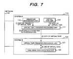
- FIG. 7is an embodiment of renting processing of a virtual tape renting task.
- FIG. 8is an embodiment of returning processing at the completion of the virtual tape renting task.
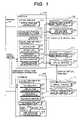
- FIG. 1is a configuration diagram of a network system which connects, via a network, a computer system and another computer system including an embodiment of the present invention.
- An embodiment in which virtual tape transfer processing is performed between a system incorporating a virtual tape unit and another systemwill be described using FIG. 1 .
- the solid line arrowsindicate data flows, and the dashed arrows indicate processing flows.
- a system A 110is connected to a virtual tape unit 130 and has a virtual tape transfer processing unit 111 and a virtual tape transfer processing unit operation instruction part 119 .
- the virtual tape transfer processing unit 111has a control part 112 , a virtual tape input/output part 113 , an exclusive processing part 114 , a file transfer part 115 , an expiration date management part 116 , virtual tape management information 117 , and a virtual tape file 118 .
- a system B 120has a virtual tape transfer processing unit 121 and a tape using task execution part 129 .
- the virtual tape transfer processing unit 121has a control part 122 , a virtual tape input/output part 123 , an exclusive processing part 124 , a file transfer part 125 , an input/output request conversion part 126 , virtual tape management information 127 , and a virtual tape file 128 .
- the virtual tape unit 130has a virtual tape unit control part 131 , a virtual tape management directory 132 , and a virtual tape storage area 133 .
- the virtual tape unit control part 131 of the system A and the input/output request conversion part 126 of the system Beach have a mechanism converting an input/output request to the tape unit to input/output to/from a disk.
- the system A 110 and the system B 120are connected via a network 140 .
- Data transfer and input/output request between the systemsare performed via the network 140 .
- the virtual tape file 118 and the virtual tape file 128have a copy function between magnetic disk drives and are stored into the magnetic disk drives capable of copying the files to be asynchronous to the systems.
- FIG. 1A processing flow using a virtual tape volume of the system A 110 in input processing of the tape using task execution part 129 of the system B 120 will be described using FIG. 1 .
- the tape using task execution part 129gives a virtual tape input request.
- the exclusive processing part 124locks the virtual tape file 128 .
- the control part 122gives a virtual tape input request to the virtual tape transfer processing unit 111 .
- the exclusive processing part 114checks whether the virtual tape volume is usable. When it is usable, the virtual tape volume and the virtual tape file 118 are locked.
- the virtual tape input/output part 113creates the virtual tape management information 117 (which defines the structure of the tape file and will be described later in detail) and the virtual tape file 118 based on the virtual tape volume. That is, the virtual tape file 118 (the same data set as that of the virtual tape storage area 133 ) is created from the virtual tape storage area 133 .
- the virtual tape file 118serves as a work area to the virtual tape storage area 133 . This is for preventing the processing of the system A from being interrupted by file transfer.
- the file transfer part 115transfers the virtual tape file 118 to the virtual tape file 128 using the copy function between the magnetic disk drives so as to be asynchronous to the systems, and stores file position information on the transferred side into the virtual tape management information 117 .
- the control part 112copies the virtual tape management information 117 to the virtual tape management information 127 .
- a technique for copying data between systems without any load on a host computeris exemplified in Japanese Unexamined Patent Application Publication No. 2000-305856.
- control part 112When the current virtual tape has been transferred to the system B 120 , the control part 112 notifies, to the virtual tape transfer processing unit 121 , that the virtual tape is usable.
- the control part 122When the control part 122 receives the notification that the virtual tape is usable, the input request from the tape using task execution part 129 is converted by the input/output request conversion part 126 .
- the virtual tape management information 127 and the virtual tape file 128are used in the input processing of the tape using task execution part 129 using the virtual tape input/output part 123 .
- the control part 122When the input processing is completed, the control part 122 notifies, to the virtual tape transfer processing unit 111 , that use of the virtual tape is completed.
- the exclusive processing part 114unlocks the virtual tape volume and the virtual tape file 118 .
- the exclusive processing part 124unlocks the virtual tape file 128 .
- FIG. 1A processing flow in which the tape using task execution part 129 of the system B 120 requests output of the virtual tape volume of the system A 110 will be described using FIG. 1 .
- the tape using task execution part 129gives a virtual tape output request.
- the exclusive processing part 124locks the virtual tape file 128 .
- the control part 122gives a virtual tape output request to the virtual tape transfer processing unit 111 .
- the exclusive processing part 114checks whether the virtual tape volume is usable. When it is usable, the virtual tape volume and the virtual tape file 118 are locked. The control part 112 notifies, to the virtual tape transfer processing unit 121 , that the virtual tape is usable.
- the virtual tape volumeis, e.g., one magnetic tape and includes a plurality of files. Exclusive control is performed in the virtual tape management directory 132 for each virtual volume. Exclusive control is performed in the virtual tape management information 117 for each file.
- the input/output request conversion part 126converts the output request from the tape using task execution part 129 between the tape interface and the disk interface.
- the virtual tape input/output part 123is used to output it to the virtual tape management information 127 and the virtual tape file 128 .
- the file transfer part 125transfers the virtual tape file 128 to the virtual tape file 118 using the copy function between the magnetic disk drives so as to be asynchronous to the systems, and stores the file position information on the transferred side into the virtual tape management information 127 .
- the control part 122copies the virtual tape management information 127 to the virtual tape management information 117 to output the virtual tape volume based on the virtual tape management information 117 and the virtual tape file 118 . Specifically, it returns the data to the virtual tape storage area 133 to rewrite the virtual tape management directory 132 .
- the control part 122When the transfer of the virtual tape management information 127 and the virtual tape file 128 to the system A 110 is completed, the control part 122 notifies, to the virtual tape transfer processing unit 111 , that use of the virtual tape is completed.
- the exclusive processing part 114unlocks the virtual tape volume and the virtual tape file 118 .
- the exclusive processing part 124unlocks the virtual tape file 128 .
- the expiration date management part 116monitors a renting expiration date in the task to rent the virtual tape of the system A 110 to the system B 120 . When the expiration date is expired, it automatically performs virtual tape returning processing. The expiration date management part 116 gives a returning request. The control part 122 of the system B performs returning control.
- the virtual tape transfer processing unit operation instruction part 119outputs the request to the virtual tape transfer processing unit 111 when performing the virtual tape transfer processing from the system A side.
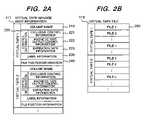
- FIG. 2Ais a structure example of the virtual tape management information 117 used for transferring a virtual tape.
- FIG. 2Bis a structure example of the virtual tape file 118 .
- the virtual tape management information 117stores a volume name 210 , control information 220 , label information 230 , and file position information 240 for each virtual tape transferred.
- the control information 220has exclusive control information 221 , magnetic tape output control information 222 , and expiration date information 223 , which are set according to a task used.
- the virtual tape file 118stores virtual tape files 250 .
- FIG. 3Ais a file copy example by the copy function between the magnetic disk drives.
- FIG. 3Bis a file position information example.
- the magnetic disk drives on the transferring side and the transferred sideare mapped in a copiable unit, respectively.
- One fileis one successive data piece on a magnetic tape.
- One file on the magnetic disk driveis divided into some successive data pieces to be written.
- the file position information 240stores data start and end positions, data continuation and end specification, and copying side block positions and copied side block positions of data for each successive data piece.
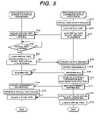
- FIG. 4is a flowchart showing a flow of input processing. The procedure of the input processing will be described using FIG. 4 .
- the tape using task execution part 129 of the system B 120gives a virtual tape input request (step 401 ).
- the system A 110 and the system B 120lock the respective targeted virtual tapes so as not to be used in other processing.
- the system B 120locks the virtual tape file 128 (step 402 ). The locking is performed by writing exclusive control specification into the exclusive control information 221 in the control information 220 in the virtual tape management information 127 by the exclusive processing part 124 .
- the control part 122gives a virtual tape input request to the virtual tape transfer processing unit 111 (step 403 ).
- the exclusive processing part 114checks whether the targeted virtual tape volume is usable (step 405 ).
- the exclusive processing part 114gives, to the virtual tape unit 130 , a request to allow the virtual tape volume to be in use, thereby writing exclusive control specification into the exclusive control information 221 of the virtual tape management information 117 to lock the virtual tape file 118 (step 406 ).
- the label information 230is stored into the targeted virtual tape management information 117 is checked.
- the update dates of the virtual tape volume and the virtual tape management information 117are compared to check whether the virtual tape is transferred (step 407 ).
- the label information 230does not exist or the update date of the virtual tape volume is later, the virtual tape is transferred.
- the virtual tape input/output part 113creates the virtual tape file 118 to be transferred based on the virtual tape storage area 133 and stores the label information of the targeted volume of the virtual tape management directory 132 into the label information 230 of the virtual tape management information 117 (step 408 ).
- the file transfer part 115uses the copy function between the magnetic disk drives to transfer the virtual tape file 118 to the virtual tape file 128 of the system B 120 so as to be asynchronous to the systems (steps 409 , 410 ).
- the file position information 240corresponding the file positions on the transferring side and the transferred side with each other is stored into the virtual tape management information 117 (step 411 ).
- the control part 112sends the virtual tape management information 117 to the virtual tape information 127 of the system B 120 (steps 412 , 413 ).
- the control part 112When the virtual tape has been transferred to the system B 120 , the control part 112 notifies, to the system B 120 , that the virtual tape is usable (step 414 ).
- the input request of the tape using task execution part 129is converted by the input/output request conversion part 126 (step 415 ).
- the virtual tape input/output part 123uses the volume name 210 and the label information 230 in the virtual tape management information 127 and the virtual tape file 128 for the input processing (step 416 ).
- the control part 122After the completion of the input processing, the control part 122 notifies, to the system A 110 , that use of the virtual tape is completed (step 417 ).
- the exclusive processing part 114gives, to the virtual tape unit 130 , a request to complete use of the virtual tape volume, removes the exclusive control specification of the exclusive control information 221 of the virtual tape management information 117 , and unlocks the virtual tape file 118 (step 418 ).
- the exclusive processing part 124removes the exclusive control specification of the exclusive control information 221 of the virtual tape management information 127 , and unlocks the virtual tape file 128 (step 419 ).
- the virtual tape transfer processing unit operation instruction part 119performs virtual tape transfer processing to the system B 120 at a predetermined timing or at a timing for each fixed time.
- the virtual tape transfer processingis eliminated at the input processing to make the input processing faster.
- the tape using task execution part 129has the effect of executing the processing quickly without waiting for the transfer of the virtual tape.
- the virtual tape transfer processing flowis as follows.
- the virtual tape transfer processing unit operation instruction part 119gives a tape transfer request.
- the system A 110 and the system B 120lock the virtual tapes.
- the virtual tape input/output part 113creates the virtual tape file 118 to be transferred based on the virtual tape storage area 133 to store the label information of the targeted volume of the virtual tape management directory 132 into the label information 230 of the virtual tape management information 117 .
- the file transfer part 115sends the virtual tape file 118 to the system B 120 to store the file position information 240 into the virtual tape management information 117 .
- the control part 112sends the virtual tape management information 117 to the system B 120 .
- FIG. 5is a flowchart showing a flow of output processing. The procedure of the output processing will be described using FIG. 5 .
- the tape using task execution part 129 of the system B 120gives a virtual tape output request (step 501 ).
- the system A 110 and the system B 120lock the targeted virtual tapes so as not to be used in other processing.
- the system B 120locks the virtual tape file 128 (step 502 ).
- the lockingis performed by writing exclusive control specification into the exclusive control information 221 in the control information 220 in the virtual tape management information 127 by the exclusive processing part 124 .
- the control part 122gives a virtual tape output request to the virtual tape transfer processing unit 111 (step 503 ).
- the exclusive processing part 114checks whether the targeted virtual tape volume is usable (step 505 ).
- the exclusive processing part 114gives, to the virtual tape unit, a request to allow the virtual tape volume to be in use, thereby writing exclusive control specification into the exclusive control information 221 of the virtual tape management information 117 to lock the virtual tape file 118 (step 506 ).
- the control part 112notifies, to the system B 120 , that the virtual tape is usable (step 507 ).
- the output request of the tape using task execution part 129is converted by the input/output request conversion part 126 (step 508 ).
- the virtual tape input/output part 123stores the output result into the label information 230 in the virtual tape management information 127 and the virtual tape file 128 (step 509 ). After the completion of the output processing, the virtual tape is transferred.
- the file transfer part 125uses the copy function between the magnetic disk drives which is known in the control of a magnetic disk to transfer the virtual tape file 128 to the virtual tape file 118 of the system A 110 so as to be asynchronous to the systems (steps 510 , 511 ).
- the file position information 240 corresponding the file positions on the transferring side and the transferred side with each otheris stored into the virtual tape management information 127 (step 512 ).
- the control part 122sends the virtual tape management information 127 to the virtual tape information 117 of the system A 110 (steps 513 , 514 ).
- the virtual tape input/output part 113outputs the virtual tape volume based on the virtual tape management information 117 and the virtual tape file 118 ( 515 ).
- the control part 122After the completion the output processing of the virtual tape volume, the control part 122 notifies, to the system A 110 , that use of the virtual tape is completed (step 516 ).
- the exclusive processing part 114gives a request to complete use of the virtual tape volume to the virtual tape unit 130 , removes the exclusive control specification of the exclusive control information 221 of the virtual tape management information 117 , and unlocks the virtual tape file 118 (step 517 ).
- the exclusive processing part 124removes the exclusive control specification of the exclusive control information 221 of the virtual tape management information 127 to unlock the virtual tape file 128 (step 518 ).
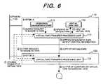
- FIG. 6is an embodiment in which the virtual tape is automatically outputted to the magnetic tape on another system.
- the drawingassumes FIGS. 1 and 2 and represents those related to this embodiment.
- a backup copycan be created at a remote place to take precautions against disaster.
- the virtual tape transfer processing unit operation instruction part 119specifies the presence or absence of erasing of a virtual tape on the outputting side to give a request to output the virtual tape of the system A 110 to the magnetic tape of the system B 120 .
- the virtual tape input/output part 113writes output specification to the magnetic tape into the magnetic tape output control information 222 in the control information 220 of the virtual tape management information 117 to specify the presence or absence of erasing of the virtual tape on the outputting side.
- the virtual tapeis transferred to the system B 120 .
- the control part 112gives an output request to the magnetic tape to the virtual tape transfer processing unit 121 .
- the virtual tape input/output part 123checks the magnetic tape output control information 222 of the virtual tape management information 127 to output the virtual tape with the output specification to the magnetic tape to an actual magnetic tape.
- the control part 122gives an erasing request of the targeted virtual tape to the virtual tape transfer processing unit 111 to erase the virtual tape on the outputting side.
- FIG. 7is an embodiment of a virtual tape renting task.
- FIG. 8is an embodiment of virtual tape returning processing at the completion of the renting task.
- the virtual tape transfer processing unit operation instruction part 119gives a renting request of the virtual tape to the virtual tape transfer processing unit 111 .
- the virtual tape input/output part 113specifies the expiration date information 223 of the virtual tape management information 117 to transfer the virtual tape of the system A 110 to the system B 120 , as in the input processing.
- the virtual tape expiration dateis monitored by the expiration date management part 116 .
- the expiration date management part 116checks the expiration date information 223 of the virtual tape management information 117 at a predetermined timing or a timing for each fixed time. When the expiration date is expired, it gives a returning request of the virtual tape to the virtual tape transfer processing unit 121 .
- the virtual tape of the system B 120is outputted to the virtual tape volume on the virtual tape unit 130 of the system A 110 , as in the output processing.
- the magnetic tapeis not used for transferring the virtual tape volume, thereby shortening the processing time and reducing the operation cost of the magnetic tape.
- the copy function between the magnetic disk drives which is operated to be asynchronous to the systemsis used to copy the virtual tape file to reduce the load of the systems of the file transfer processing.
- the file on the magnetic diskis used as the file of the magnetic tape by conversion of the input/output request. It is unnecessary to change the conventional task. The cost concerning the change of the task can be reduced.
- the magnetic diskis mainly described. It is not limited to the type of a recording medium and may be an optical disk.
- the transfer time of the virtual tape volume between the systemscan be shortened.
Landscapes
- Engineering & Computer Science (AREA)
- Theoretical Computer Science (AREA)
- Human Computer Interaction (AREA)
- Physics & Mathematics (AREA)
- General Engineering & Computer Science (AREA)
- General Physics & Mathematics (AREA)
- Information Retrieval, Db Structures And Fs Structures Therefor (AREA)
Abstract
Description
Claims (2)
Applications Claiming Priority (2)
| Application Number | Priority Date | Filing Date | Title |
|---|---|---|---|
| JP2003-017033 | 2003-01-27 | ||
| JP2003017033AJP2004227448A (en) | 2003-01-27 | 2003-01-27 | Tape management method and system |
Publications (2)
| Publication Number | Publication Date |
|---|---|
| US20040148458A1 US20040148458A1 (en) | 2004-07-29 |
| US7007129B2true US7007129B2 (en) | 2006-02-28 |
Family
ID=32732829
Family Applications (1)
| Application Number | Title | Priority Date | Filing Date |
|---|---|---|---|
| US10/695,890Expired - Fee RelatedUS7007129B2 (en) | 2003-01-27 | 2003-10-30 | Tape management method by which a virtual tape file emulated on a disk drive is copied between disk drives |
Country Status (2)
| Country | Link |
|---|---|
| US (1) | US7007129B2 (en) |
| JP (1) | JP2004227448A (en) |
Cited By (8)
| Publication number | Priority date | Publication date | Assignee | Title |
|---|---|---|---|---|
| US20060059188A1 (en)* | 2004-09-16 | 2006-03-16 | Tetsuya Shirogane | Operation environment associating data migration method |
| US20070136519A1 (en)* | 2003-07-10 | 2007-06-14 | Hitachi, Ltd. | Offsite management using disk based tape library and vault system |
| US20090237828A1 (en)* | 2008-03-19 | 2009-09-24 | Hitachi, Ltd. | Tape device data transferring method and tape management system |
| US20100100676A1 (en)* | 2008-10-22 | 2010-04-22 | Neil Johnson | Systems And Methods Of Presenting Virtual Tape Products To A Client |
| US20110066799A1 (en)* | 2009-09-15 | 2011-03-17 | Stephen Gold | Enhanced virtual storage replication |
| US9348513B2 (en) | 2011-07-27 | 2016-05-24 | Hewlett Packard Enterprise Development Lp | SAS virtual tape drive |
| US20170052718A1 (en)* | 2015-08-21 | 2017-02-23 | International Business Machines Corporation | Duplexing file system data |
| US11914883B2 (en) | 2022-03-04 | 2024-02-27 | International Business Machines Corporation | Copy from LTFS to disk |
Families Citing this family (13)
| Publication number | Priority date | Publication date | Assignee | Title |
|---|---|---|---|---|
| US20040181388A1 (en)* | 2003-03-11 | 2004-09-16 | Yung Yip | System having tape drive emulator and data tape cartridge housing carrying multiple disk drives |
| JP4559046B2 (en)* | 2003-08-04 | 2010-10-06 | 株式会社日立製作所 | Virtual tape library device |
| JP4604669B2 (en) | 2004-11-15 | 2011-01-05 | 株式会社日立製作所 | Operation method of virtual tape volume |
| JP4585292B2 (en)* | 2004-11-26 | 2010-11-24 | 株式会社日立製作所 | File allocation method and virtual tape library system |
| US7631213B2 (en)* | 2004-12-06 | 2009-12-08 | Johnson R Brent | Data center virtual tape off-site disaster recovery planning and implementation system |
| JP4756545B2 (en) | 2006-05-15 | 2011-08-24 | 株式会社日立製作所 | Storage system having a plurality of tape devices |
| WO2009040954A1 (en)* | 2007-09-28 | 2009-04-02 | Fujitsu Limited | Virtual tape device at original center, virtual tape device at duplicate center, virtual library system and virtual tape control method |
| US8214584B2 (en)* | 2008-08-29 | 2012-07-03 | Johnson R Brent | Secure virtual tape management system with early read support options |
| JP6176214B2 (en)* | 2014-09-25 | 2017-08-09 | 日本電気株式会社 | Storage system, storage system control method, and virtual tape device control program |
| US10013193B2 (en)* | 2016-08-19 | 2018-07-03 | International Business Machines Corporation | Self-expiring data in a virtual tape server |
| US10007452B2 (en)* | 2016-08-19 | 2018-06-26 | International Business Machines Corporation | Self-expiring data in a virtual tape server |
| US10423336B2 (en)* | 2017-11-28 | 2019-09-24 | International Business Machines Corporation | Fast locate using imitation reads on tape drives |
| US11474753B2 (en)* | 2020-10-30 | 2022-10-18 | Commvault Systems, Inc. | Systems and methods for backing up to a virtual tape library |
Citations (22)
| Publication number | Priority date | Publication date | Assignee | Title |
|---|---|---|---|---|
| US5127094A (en)* | 1987-11-09 | 1992-06-30 | Hitachi, Ltd. | Virtual storage type computer system |
| US5297124A (en)* | 1992-04-24 | 1994-03-22 | Miltope Corporation | Tape drive emulation system for a disk drive |
| US5438674A (en)* | 1988-04-05 | 1995-08-01 | Data/Ware Development, Inc. | Optical disk system emulating magnetic tape units |
| JPH11272426A (en) | 1998-03-20 | 1999-10-08 | Fujitsu Ltd | Data copying / restoring system and recording medium |
| US6128698A (en)* | 1997-08-04 | 2000-10-03 | Exabyte Corporation | Tape drive emulator for removable disk drive |
| US6453277B1 (en)* | 1999-01-28 | 2002-09-17 | Computer Associates Think, Inc. | Virtual I/O emulator in a mainframe environment |
| US20020144044A1 (en)* | 2001-03-29 | 2002-10-03 | Moon William G. | Removable disk storage array emulating tape library having backup and archive capability |
| US20030037211A1 (en)* | 2001-08-08 | 2003-02-20 | Alexander Winokur | Data backup method and system using snapshot and virtual tape |
| US6557073B1 (en)* | 1998-06-30 | 2003-04-29 | Fujitsu Limited | Storage apparatus having a virtual storage area |
| US20030135672A1 (en)* | 2002-01-14 | 2003-07-17 | Imation Corp. | System having tape drive emulator and data cartridge carrying a non-tape storage medium |
| US20030154340A1 (en)* | 2002-02-13 | 2003-08-14 | Thomas Bolt | Use of the universal serial bus as an internal architecture within IDE disk array |
| US20040034811A1 (en) | 2002-08-14 | 2004-02-19 | Alacritus, Inc. | Method and system for copying backup data |
| US6701455B1 (en)* | 2000-08-29 | 2004-03-02 | Hitachi, Ltd. | Remote copy system with data integrity |
| US20040044828A1 (en)* | 2002-08-29 | 2004-03-04 | International Business Machines Corporation | Method and apparatus for read-only recovery in a dual copy storage system |
| US20040044855A1 (en)* | 2002-08-29 | 2004-03-04 | International Business Machines Corporation | Method, system, and article of manufacture for borrowing physical volumes |
| US20040098244A1 (en)* | 2002-11-14 | 2004-05-20 | Imation Corp. | Method and system for emulating tape storage format using a non-tape storage medium |
| US6745212B2 (en) | 2001-06-27 | 2004-06-01 | International Business Machines Corporation | Preferential caching of uncopied logical volumes in an IBM peer-to-peer virtual tape server |
| US20040111251A1 (en)* | 2002-12-09 | 2004-06-10 | Alacritus, Inc. | Method and system for emulating tape libraries |
| US20040148484A1 (en)* | 2003-01-23 | 2004-07-29 | Hitachi, Ltd. | Throttling in storage systems |
| US20040153614A1 (en) | 2003-02-05 | 2004-08-05 | Haim Bitner | Tape storage emulation for open systems environments |
| US6779058B2 (en) | 2001-07-13 | 2004-08-17 | International Business Machines Corporation | Method, system, and program for transferring data between storage devices |
| US20040230724A1 (en)* | 2003-05-14 | 2004-11-18 | Roger Stager | Method and system for data compression and compression estimation in a virtual tape library environment |
- 2003
- 2003-01-27JPJP2003017033Apatent/JP2004227448A/enactivePending
- 2003-10-30USUS10/695,890patent/US7007129B2/ennot_activeExpired - Fee Related
Patent Citations (22)
| Publication number | Priority date | Publication date | Assignee | Title |
|---|---|---|---|---|
| US5127094A (en)* | 1987-11-09 | 1992-06-30 | Hitachi, Ltd. | Virtual storage type computer system |
| US5438674A (en)* | 1988-04-05 | 1995-08-01 | Data/Ware Development, Inc. | Optical disk system emulating magnetic tape units |
| US5297124A (en)* | 1992-04-24 | 1994-03-22 | Miltope Corporation | Tape drive emulation system for a disk drive |
| US6128698A (en)* | 1997-08-04 | 2000-10-03 | Exabyte Corporation | Tape drive emulator for removable disk drive |
| JPH11272426A (en) | 1998-03-20 | 1999-10-08 | Fujitsu Ltd | Data copying / restoring system and recording medium |
| US6557073B1 (en)* | 1998-06-30 | 2003-04-29 | Fujitsu Limited | Storage apparatus having a virtual storage area |
| US6453277B1 (en)* | 1999-01-28 | 2002-09-17 | Computer Associates Think, Inc. | Virtual I/O emulator in a mainframe environment |
| US6701455B1 (en)* | 2000-08-29 | 2004-03-02 | Hitachi, Ltd. | Remote copy system with data integrity |
| US20020144044A1 (en)* | 2001-03-29 | 2002-10-03 | Moon William G. | Removable disk storage array emulating tape library having backup and archive capability |
| US6745212B2 (en) | 2001-06-27 | 2004-06-01 | International Business Machines Corporation | Preferential caching of uncopied logical volumes in an IBM peer-to-peer virtual tape server |
| US6779058B2 (en) | 2001-07-13 | 2004-08-17 | International Business Machines Corporation | Method, system, and program for transferring data between storage devices |
| US20030037211A1 (en)* | 2001-08-08 | 2003-02-20 | Alexander Winokur | Data backup method and system using snapshot and virtual tape |
| US20030135672A1 (en)* | 2002-01-14 | 2003-07-17 | Imation Corp. | System having tape drive emulator and data cartridge carrying a non-tape storage medium |
| US20030154340A1 (en)* | 2002-02-13 | 2003-08-14 | Thomas Bolt | Use of the universal serial bus as an internal architecture within IDE disk array |
| US20040034811A1 (en) | 2002-08-14 | 2004-02-19 | Alacritus, Inc. | Method and system for copying backup data |
| US20040044855A1 (en)* | 2002-08-29 | 2004-03-04 | International Business Machines Corporation | Method, system, and article of manufacture for borrowing physical volumes |
| US20040044828A1 (en)* | 2002-08-29 | 2004-03-04 | International Business Machines Corporation | Method and apparatus for read-only recovery in a dual copy storage system |
| US20040098244A1 (en)* | 2002-11-14 | 2004-05-20 | Imation Corp. | Method and system for emulating tape storage format using a non-tape storage medium |
| US20040111251A1 (en)* | 2002-12-09 | 2004-06-10 | Alacritus, Inc. | Method and system for emulating tape libraries |
| US20040148484A1 (en)* | 2003-01-23 | 2004-07-29 | Hitachi, Ltd. | Throttling in storage systems |
| US20040153614A1 (en) | 2003-02-05 | 2004-08-05 | Haim Bitner | Tape storage emulation for open systems environments |
| US20040230724A1 (en)* | 2003-05-14 | 2004-11-18 | Roger Stager | Method and system for data compression and compression estimation in a virtual tape library environment |
Cited By (14)
| Publication number | Priority date | Publication date | Assignee | Title |
|---|---|---|---|---|
| US20070136519A1 (en)* | 2003-07-10 | 2007-06-14 | Hitachi, Ltd. | Offsite management using disk based tape library and vault system |
| US7631157B2 (en) | 2003-07-10 | 2009-12-08 | Hitachi, Ltd. | Offsite management using disk based tape library and vault system |
| US20100049924A1 (en)* | 2003-07-10 | 2010-02-25 | Hitachi, Ltd. | Offsite management using disk based tape library and vault system |
| US7996635B2 (en) | 2003-07-10 | 2011-08-09 | Hitachi, Ltd. | Offsite management using disk based tape library and vault system |
| US20060059188A1 (en)* | 2004-09-16 | 2006-03-16 | Tetsuya Shirogane | Operation environment associating data migration method |
| US20090237828A1 (en)* | 2008-03-19 | 2009-09-24 | Hitachi, Ltd. | Tape device data transferring method and tape management system |
| US8489808B2 (en) | 2008-10-22 | 2013-07-16 | Hewlett-Packard Development Company, L.P. | Systems and methods of presenting virtual tape products to a client |
| US20100100676A1 (en)* | 2008-10-22 | 2010-04-22 | Neil Johnson | Systems And Methods Of Presenting Virtual Tape Products To A Client |
| US20110066799A1 (en)* | 2009-09-15 | 2011-03-17 | Stephen Gold | Enhanced virtual storage replication |
| US8850142B2 (en)* | 2009-09-15 | 2014-09-30 | Hewlett-Packard Development Company, L.P. | Enhanced virtual storage replication |
| US9348513B2 (en) | 2011-07-27 | 2016-05-24 | Hewlett Packard Enterprise Development Lp | SAS virtual tape drive |
| US20170052718A1 (en)* | 2015-08-21 | 2017-02-23 | International Business Machines Corporation | Duplexing file system data |
| US10168920B2 (en)* | 2015-08-21 | 2019-01-01 | International Business Machines Corporation | Duplexing file system data |
| US11914883B2 (en) | 2022-03-04 | 2024-02-27 | International Business Machines Corporation | Copy from LTFS to disk |
Also Published As
| Publication number | Publication date |
|---|---|
| JP2004227448A (en) | 2004-08-12 |
| US20040148458A1 (en) | 2004-07-29 |
Similar Documents
| Publication | Publication Date | Title |
|---|---|---|
| US7007129B2 (en) | Tape management method by which a virtual tape file emulated on a disk drive is copied between disk drives | |
| JP3600414B2 (en) | Data backup / restore method and system in multiple system environment | |
| US7461201B2 (en) | Storage control method and system for performing backup and/or restoration | |
| US6745304B2 (en) | Method and device for storing computer data with back-up operations | |
| JP2004054720A (en) | Disk array system backup method | |
| US8745345B2 (en) | Backup copy enhancements to reduce primary version access | |
| US20040103247A1 (en) | Storage control apparatus and control method thereof | |
| US6453396B1 (en) | System, method and computer program product for hardware assisted backup for a computer mass storage system | |
| JP3904894B2 (en) | Backup management method and storage control device used in this method | |
| CN101034363B (en) | Data backup device, data backup method | |
| JP4074442B2 (en) | Method, apparatus, system, program and storage medium for data backup | |
| JP2005182220A (en) | Copying device, copying method, copying program, block identification information acquisition program, and recording medium | |
| US20140089263A1 (en) | File recording apparatus, file system management method, and changer drive | |
| JP2005234860A (en) | Version management system, version management server apparatus, and storage device control apparatus | |
| US7191197B2 (en) | Method and apparatus for detecting and transferring data of different formats | |
| US6175933B1 (en) | Recovery of file transfers in a data processing system | |
| JP2008084327A (en) | Method, apparatus, system, program and storage medium for data backup | |
| WO2009093280A1 (en) | Storage device | |
| JP3043662B2 (en) | Data backup method | |
| JP3794322B2 (en) | Data copy system | |
| JP2000305719A (en) | Data backup method in information processing system | |
| US20060143423A1 (en) | Storage device, data processing method thereof, data processing program thereof, and data processing system | |
| JPH0793101A (en) | Data backup device | |
| JPS6312300B2 (en) | ||
| JP2005316697A (en) | Disk array system and method for data backup |
Legal Events
| Date | Code | Title | Description |
|---|---|---|---|
| AS | Assignment | Owner name:HITACHI, LTD., JAPAN Free format text:ASSIGNMENT OF ASSIGNORS INTEREST;ASSIGNORS:SEKINE, MICHIAKI;MURAKOSO, TAKEAKI;REEL/FRAME:016990/0123;SIGNING DATES FROM 20031016 TO 20031017 | |
| FEPP | Fee payment procedure | Free format text:PAYER NUMBER DE-ASSIGNED (ORIGINAL EVENT CODE: RMPN); ENTITY STATUS OF PATENT OWNER: LARGE ENTITY Free format text:PAYOR NUMBER ASSIGNED (ORIGINAL EVENT CODE: ASPN); ENTITY STATUS OF PATENT OWNER: LARGE ENTITY | |
| FPAY | Fee payment | Year of fee payment:4 | |
| FEPP | Fee payment procedure | Free format text:PAYER NUMBER DE-ASSIGNED (ORIGINAL EVENT CODE: RMPN); ENTITY STATUS OF PATENT OWNER: LARGE ENTITY Free format text:PAYOR NUMBER ASSIGNED (ORIGINAL EVENT CODE: ASPN); ENTITY STATUS OF PATENT OWNER: LARGE ENTITY | |
| FPAY | Fee payment | Year of fee payment:8 | |
| FEPP | Fee payment procedure | Free format text:MAINTENANCE FEE REMINDER MAILED (ORIGINAL EVENT CODE: REM.) | |
| LAPS | Lapse for failure to pay maintenance fees | Free format text:PATENT EXPIRED FOR FAILURE TO PAY MAINTENANCE FEES (ORIGINAL EVENT CODE: EXP.) | |
| STCH | Information on status: patent discontinuation | Free format text:PATENT EXPIRED DUE TO NONPAYMENT OF MAINTENANCE FEES UNDER 37 CFR 1.362 | |
| FP | Lapsed due to failure to pay maintenance fee | Effective date:20180228 |