US7006845B2 - Method and system for interfacing a portable transceiver in a telematics system - Google Patents
Method and system for interfacing a portable transceiver in a telematics systemDownload PDFInfo
- Publication number
- US7006845B2 US7006845B2US10/115,761US11576102AUS7006845B2US 7006845 B2US7006845 B2US 7006845B2US 11576102 AUS11576102 AUS 11576102AUS 7006845 B2US7006845 B2US 7006845B2
- Authority
- US
- United States
- Prior art keywords
- wireless transceiver
- vehicle
- portable wireless
- power
- transceiver
- Prior art date
- Legal status (The legal status is an assumption and is not a legal conclusion. Google has not performed a legal analysis and makes no representation as to the accuracy of the status listed.)
- Expired - Lifetime, expires
Links
- 238000000034methodMethods0.000titleclaimsabstractdescription25
- 230000004044responseEffects0.000claimsabstractdescription19
- 230000000977initiatory effectEffects0.000claimsdescription3
- 238000013475authorizationMethods0.000claimsdescription2
- 230000006870functionEffects0.000abstractdescription30
- 230000008901benefitEffects0.000description4
- 230000001413cellular effectEffects0.000description3
- 238000005516engineering processMethods0.000description3
- 230000000881depressing effectEffects0.000description2
- 230000006855networkingEffects0.000description2
- 239000000523sampleSubstances0.000description2
- 230000000153supplemental effectEffects0.000description2
- 230000002411adverseEffects0.000description1
- 230000005540biological transmissionEffects0.000description1
- 238000001514detection methodMethods0.000description1
- 238000009434installationMethods0.000description1
- 230000010354integrationEffects0.000description1
- 230000003993interactionEffects0.000description1
- 230000006386memory functionEffects0.000description1
- 238000012544monitoring processMethods0.000description1
- 230000000737periodic effectEffects0.000description1
- 230000008569processEffects0.000description1
- 230000003068static effectEffects0.000description1
- 230000000007visual effectEffects0.000description1
- 230000002618waking effectEffects0.000description1
Images


Classifications
- H—ELECTRICITY
- H04—ELECTRIC COMMUNICATION TECHNIQUE
- H04B—TRANSMISSION
- H04B1/00—Details of transmission systems, not covered by a single one of groups H04B3/00 - H04B13/00; Details of transmission systems not characterised by the medium used for transmission
- H04B1/38—Transceivers, i.e. devices in which transmitter and receiver form a structural unit and in which at least one part is used for functions of transmitting and receiving
- H04B1/3827—Portable transceivers
- H04B1/3877—Arrangements for enabling portable transceivers to be used in a fixed position, e.g. cradles or boosters
- H—ELECTRICITY
- H04—ELECTRIC COMMUNICATION TECHNIQUE
- H04W—WIRELESS COMMUNICATION NETWORKS
- H04W52/00—Power management, e.g. Transmission Power Control [TPC] or power classes
- H04W52/02—Power saving arrangements
- H04W52/0209—Power saving arrangements in terminal devices
- H04W52/0225—Power saving arrangements in terminal devices using monitoring of external events, e.g. the presence of a signal
- H04W52/0229—Power saving arrangements in terminal devices using monitoring of external events, e.g. the presence of a signal where the received signal is a wanted signal
- Y—GENERAL TAGGING OF NEW TECHNOLOGICAL DEVELOPMENTS; GENERAL TAGGING OF CROSS-SECTIONAL TECHNOLOGIES SPANNING OVER SEVERAL SECTIONS OF THE IPC; TECHNICAL SUBJECTS COVERED BY FORMER USPC CROSS-REFERENCE ART COLLECTIONS [XRACs] AND DIGESTS
- Y02—TECHNOLOGIES OR APPLICATIONS FOR MITIGATION OR ADAPTATION AGAINST CLIMATE CHANGE
- Y02D—CLIMATE CHANGE MITIGATION TECHNOLOGIES IN INFORMATION AND COMMUNICATION TECHNOLOGIES [ICT], I.E. INFORMATION AND COMMUNICATION TECHNOLOGIES AIMING AT THE REDUCTION OF THEIR OWN ENERGY USE
- Y02D30/00—Reducing energy consumption in communication networks
- Y02D30/70—Reducing energy consumption in communication networks in wireless communication networks
Definitions
- This inventionrelates to a method and system for interfacing a portable transceiver in a telematics system.
- Wireless transceiverssuch as cellular telephones
- Portable devicesare interfaced with the vehicle either through hardware links such as a cradle in the vehicle or through short-range wireless links of the type used in wireless networking.
- Short range wireless linkstypically use very low power, operate at upper megahertz or in the gigahertz frequencies, and have the ability to communicate a limited range, for example 30 to 90 feet (or more depending upon local regulations and/or the standard implemented).
- Portable hand-held transceiverssuch as analog or digital cellular phones, typically have a power-off state, where all functions are disabled, and a power-on state, where functions are enabled. When in the power-on state, the device may be in a power conservation mode, which conserves energy, but still allows initiation of receipt and transmission of calls.
- this inventionprovides a method and system for interfacing a vehicle and hand-held transceiver.
- this inventionprovides a method and system for interfacing a vehicle and hand-held transceiver to provide enhanced functionality over a wireless link.
- this inventionprovides a method of interfacing a portable wireless transceiver in a telematics system comprising the steps of: a) bringing the portable wireless transceiver into a proximity of a vehicle, wherein the portable wireless transceiver has short range and long range wireless transceiving functions; b) automatically switching the portable wireless transceiver from a power-off state to a power-on state in response to a short range wireless signal from the vehicle; and c) operating the portable wireless transceiver as a telecommunications device for at least one system within the vehicle, wherein the portable wireless transceiver is coupled to the vehicle through a short range wireless link.
- this inventionadvantageously also comprises the steps of: removing the portable wireless transceiver from the proximity of the first vehicle; and automatically switching the portable wireless transceiver from the power-on state to the power-off state in response to the removing of the portable wireless transceiver from the proximity of the first vehicle.
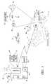
- FIG. 1illustrates an example system for implementing this invention
- FIG. 2illustrates example method steps and example functions of the system shown in FIG. 1 ;
- FIG. 3illustrates further example method steps and example functions of the system shown in FIG. 1 .
- FIG. 1illustrates an example system according to this invention including a wireless transceiver 10 such as, for example, a hand-held portable cellular telephone that includes one or more modes for communicating over one or more wireless public or private telecommunications networks.
- the wireless transceiver 10may be a stand-alone unit or may be embedded in another portable electronic unit such as, for example, a hand-held or laptop computer.
- the transceiver 10includes circuitry 11 (long-range transceiver) for transmitting and receiving over the telecommunications network as controlled by the processor (or controller) 12 in a known manner.
- the processor 12is coupled to power-on and power-off functions 20 and 21 , respectively, of a known type that power on and power off the wireless transceiver 10 in response to known user inputs, such as an operator depressing one or more buttons dedicated to power control functions. Additionally, the power-on and power-off functions respond to signals from wireless link unit 18 to control power-on and power-off functions of the wireless transceiver 10 as described herein.
- the wireless link unit 18is a short-range transceiver of any type suitable for establishing a working connection with one or more compatible wireless link units on other devices.
- the particular standard used for the short range transceiver to establish the short range wireless link described hereincan be any published standard desired by the system designer capable of meeting the functions described herein, or may be a custom standard that deviates from published standards, for example, to include increased security or to include functions not included in published standards.
- the implementation of short-range wireless communications or network linksis known to those skilled in the art.
- the wireless transceiver 10includes a battery 14 for providing power to the device in a known manner.
- the wireless transceiver 10also includes a standby power function 16 for maintaining the wireless link unit 18 in standby mode allowing the wireless link unit 18 to perform monitor function 22 , monitoring for wireless interfacing even when the wireless transceiver 10 is in the power-off state.
- the standby power function 16may be part of the battery 14 , which will not adversely affect battery life due to the low current draw required to maintain the wireless link circuit 18 in standby mode.
- a separate small battery within the wireless transceiver 10 or within the wireless link unit 18can provide the standby power function. This separate battery can be charged by the battery 14 , for example, when the unit is in the power-on state or can be a replaceable battery.
- the vehicle 30includes a telematics unit 32 , with its internal processor 38 coupled to a wireless link unit 42 for short-range wireless communications for wireless networking and bussing functions.
- the wireless link unit 42is capable of interfacing with wireless link unit 18 .
- the telematics unit 32may also include its own transceiver 40 for communicating through the wireless telecommunications network, but this transceiver 40 is optional if the system designer desires that the wireless transceiver 10 be the system's primary device for communicating with the wireless telecommunications network.
- the processor 38is coupled to a bus 44 (of any known type, including but not limited to Class II, or other hardwired bus or any functional wireless bus) for communicating with other in-vehicle processors 36 and/or sensors 34 for performing known telematics services functions.
- the telematics unit 32also interfaces with the vehicle audio system (represented by speaker 46 ), to broadcast audible messages to the vehicle user and receives inputs from one or more in-cabin microphones 48 . Additionally, if a visual display and keyboard or touch screen are included in the vehicle, the telematics unit 32 may interface with the vehicle operator through those units.
- Reference 60represents a vehicle that does not have authority to access services from wireless transceiver 10 in accordance with this invention.
- Step 70the wireless transceiver is brought into proximity of vehicle 30 , for example, by the user possessing the wireless transceiver 10 approaching or getting into the vehicle.
- Step 71represents the configuration of the wireless transceiver 10 to recognize the vehicle 30 . Any number of methods can achieve this.
- the wireless link unit 18can be pre-programmed by the vehicle OEM and sold to the user or phone retailer for installation into wireless transceiver 10 for the benefit of the vehicle owner. Or for example, referring now also to FIG.
- the vehicle 30under control of processor 38 , when the vehicle 30 is started, if it does not establish a link with a wireless transceiver because the transceiver has not been configured to accept a link from vehicle 30 , the telematics unit 32 reports this fact to the user through the vehicle audio system (step 100 ).
- the vehiclecan announce that there was a failure to link to the wireless transceiver 10 .
- the wireless link unit 18does allow the vehicle to recognize that it is present, though no operating network link supporting telematics services is created.
- the telematics unit 32knowing that a wireless transceiver 10 suitable for use is present, requests, at step 104 , to the user through one of the user interfaces (such as audio system 46 ) whether the vehicle should initiate configuration of the wireless transceiver 10 .
- the vehicleinitiates configuration of the wireless transceiver 10 .
- Any type of wireless configuration designed to ensure a secure connection with the wireless transceivercan be used, and many examples of technology for creating secure connections are known to those skilled in the art.
- the vehicleoffers a recognition code to the wireless transceiver 10 .
- the wireless transceiver 10then waits for input from the user authorizing the wireless transceiver 10 to accept and store the recognition code. Once the wireless transceiver accepts and stores the recognition code, the wireless transceiver will automatically accept network connectivity to the vehicle when in proximity of the vehicle allowing communications through the wireless link units 18 and 42 .
- recognition codewhen used in this example means any type of code or algorithm or method for allowing secure connection, including but not limited to those using various encryption technologies or password technologies, whether static or dynamic. It will also be recognized that, in an alternative to the wireless transceiver 10 storing a recognition code from the vehicle, the vehicle stores an access or recognition code received from the wireless transceiver, or both the vehicle and wireless transceiver exchange codes.
- Step 72represents the initiation of the wireless link recognition function by the vehicle.
- the vehicle telematics unit 32probes through its wireless link unit 42 for wireless transceiver 10 .
- This probingmay be initiated upon opening of the car door, upon ignition on of the vehicle, upon sensing an occupant within the vehicle or other appropriate trigger, or this probing can be a continuous or periodic function, using low current draw through wireless link unit 42 so as not to drain the vehicle battery.
- Step 74represents the recognition process within wireless transceiver 10 .
- the wireless transceiver 10determines whether the vehicle probing it has authority to automatically power-on the wireless transceiver 10 . This is accomplished either through the wireless link unit 18 waking up the processor 12 for the limited purpose of determining whether to accept a link with vehicle 30 or through functions or circuitry (such as an application specific integrated circuit) included within or in support of wireless link unit 18 .
- the latter examplehas the benefit of not requiring wake-up of the cell phone processor until after authorization for establishing a link has been verified.
- Step 76represents the power-on of the wireless transceiver 10 , which occurs if, at step 74 , it is determined that he vehicle has authority to establish a wireless link with the wireless transceiver 10 .
- the wireless transceiver 10when the wireless transceiver 10 powers-on automatically through interaction of the wireless link units 18 and 42 , the wireless transceiver 10 powers on to a limited services state. That is, the system assumes that since the wireless transceiver was switched off, the user does not desire to receive incoming calls, but desires that the phone be available only in an emergency, such as in the case of a supplemental inflatable restraint deployment sensed by telematics unit 32 , or depression of an emergency help button on the telematics unit 32 .
- the wireless transceiver 10will be switched on but will not ring in response to incoming calls and, if the system designer desires, will not acknowledge to the network receipt of network information of an incoming call. Additionally, the normal operating display for the wireless transceiver 10 (such as showing the various menu options) may remain disabled or only partially enabled. Block 86 represents operation of the wireless transceiver 10 in the partial services mode.
- the wireless transceiver 10determines that the vehicle 32 is not authorized to command automatic power-on of the wireless transceiver 10 , then the wireless transceiver 10 will not power on in response to communications from vehicle 32 . This security feature ensures that only the vehicle or vehicles authorized to utilize wireless transceiver 10 will have access to its services.
- Block 78represents the processor 12 within the wireless transceiver 10 setting a flag (any signal within any type of memory function) indicating that the wireless transceiver has been powered on through the creation of an automatic link. This flag enables the wireless transceiver to automatically power off at block 91 .
- the automatic power offis in response to the removal of the wireless transceiver from the proximity of the vehicle 30 (block 89 ) and the sensing (block 90 ) within the wireless transceiver 10 that there is no longer a short range wireless link to the vehicle 30 . This occurs when the occupant with the wireless transceiver 10 departs the vehicle and/or range of the wireless link unit 42 and/or the vehicle 30 terminates the wireless link due to sensing no occupants within the vehicle 30 . If the flag is not set at block 78 , then when the wireless transceiver 10 departs the proximity of the vehicle 32 , the wireless transceiver 10 does not automatically power off.
- Block 80represents the optional registration of the wireless transceiver 10 to the telecommunications network occurring immediately after power-up or as otherwise preferred according to the telecommunications network standards.
- the vehicleannounces over the vehicle audio system establishment of the wireless link with the wireless transceiver 10 . This informs the vehicle operator that the vehicle telematics system has communications capabilities and also that the wireless transceiver 10 has been automatically powered-on. If desired, the system designer can implement an override function allowing the user to terminate the wireless link to the vehicle.
- Blocks 82 and 84represent the functions of maintaining the wireless network link between the telematics unit 32 and the wireless transceiver 10 while the vehicle is in operation and/or the wireless transceiver 10 is in proximity to the vehicle allowing the short range wireless link between units 18 and 42 .
- Block 84represents the services that the wireless transceiver 10 provides to the vehicle while it is networked to the vehicle through the wireless link.
- Any suitable telematics service or in-vehicle wireless communications servicesmay be enabled as the system designer desires.
- Typical servicesinclude, but are not limited to: (a) allowing the in-vehicle speaker and microphones to be enabled as part of a speaker phone system for the wireless transceiver 10 for hands-free operation of wireless phone calls through the telecommunications network; (b) emergency communications services such as (i) in response to supplemental inflatable restraint deployment, or other sensor, (ii) depression of an emergency services button, and (iii) notification for detection of car theft and tracking of stolen vehicles, etc.; and (c) convenience services such as voice access to e-mail and other voice information services.
- the wireless transceiver 10can be implemented as (a) a back-up transceiver or (b) an alternative transceiver in case the user has two different billing methods and prefers using one over the other.
- Block 88represents an optional function that may be implemented on a system that, in response to automatic power-on as described above, enables only a sub-set of the full functions of wireless transceiver 10 .
- the userif the user desires to enable the remaining functions of the wireless transceiver 10 , the user provides an input to the wireless transceiver 10 , such as depressing the power on button, which input then enables the full functions of the wireless transceiver 10 .
- the user input to enable the full functioning of the wireless transceiver 10can be by voice command through the voice interface built within the telematics unit 32 . Responsive to a user command, telematics unit 32 sends a signal over the wireless link unit 42 , to unit 18 commanding wireless transceiver 32 to enable all functions.
Landscapes
- Engineering & Computer Science (AREA)
- Computer Networks & Wireless Communication (AREA)
- Signal Processing (AREA)
- Mobile Radio Communication Systems (AREA)
Abstract
Description
Claims (14)
Priority Applications (1)
| Application Number | Priority Date | Filing Date | Title |
|---|---|---|---|
| US10/115,761US7006845B2 (en) | 2002-04-03 | 2002-04-03 | Method and system for interfacing a portable transceiver in a telematics system |
Applications Claiming Priority (1)
| Application Number | Priority Date | Filing Date | Title |
|---|---|---|---|
| US10/115,761US7006845B2 (en) | 2002-04-03 | 2002-04-03 | Method and system for interfacing a portable transceiver in a telematics system |
Publications (2)
| Publication Number | Publication Date |
|---|---|
| US20040203554A1 US20040203554A1 (en) | 2004-10-14 |
| US7006845B2true US7006845B2 (en) | 2006-02-28 |
Family
ID=33129659
Family Applications (1)
| Application Number | Title | Priority Date | Filing Date |
|---|---|---|---|
| US10/115,761Expired - LifetimeUS7006845B2 (en) | 2002-04-03 | 2002-04-03 | Method and system for interfacing a portable transceiver in a telematics system |
Country Status (1)
| Country | Link |
|---|---|
| US (1) | US7006845B2 (en) |
Cited By (30)
| Publication number | Priority date | Publication date | Assignee | Title |
|---|---|---|---|---|
| US20050177478A1 (en)* | 2003-12-15 | 2005-08-11 | General Motors Corporation | Method and system for managing promotional telematics services |
| US20050272457A1 (en)* | 2004-06-07 | 2005-12-08 | Nokia Corporation | Handling transmissions via a radio link |
| US20060211400A1 (en)* | 2005-03-18 | 2006-09-21 | Lear Corporation | System and method for vehicle module wake up in response to communication activity |
| US20070016362A1 (en)* | 2005-07-14 | 2007-01-18 | Honda Motor Co., Ltd. | System and method for synchronizing data for use in a navigation system |
| US20070123191A1 (en)* | 2005-11-03 | 2007-05-31 | Andrew Simpson | Human-machine interface for a portable electronic device |
| US20070150191A1 (en)* | 2005-12-22 | 2007-06-28 | Industrial Technology Research Institute | Portable telematics device |
| US20080129114A1 (en)* | 2006-12-04 | 2008-06-05 | Fujitsu Ten Limited | In-vehicle electronic system, in-vehicle electronic apparatus and method of controlling power supply of portable electronic device |
| US20080130206A1 (en)* | 2006-12-04 | 2008-06-05 | Fujitsu Ten Limited | Attachment and detachment mechanism for portable electronic device |
| US20080158790A1 (en)* | 2006-12-28 | 2008-07-03 | Fujitsu Ten Limited | Electronic apparatus and electronic system |
| US20080162029A1 (en)* | 2006-12-27 | 2008-07-03 | Fujitsu Ten Limited | Electronic apparatus and electronic system |
| US20080162816A1 (en)* | 2006-12-27 | 2008-07-03 | Mark Buxton | Obscuring memory access patterns |
| US20080158019A1 (en)* | 2006-12-28 | 2008-07-03 | Fujitsu Ten Limited | In-vehicle electronic apparatus and in-vehicle electronic system |
| US20080158791A1 (en)* | 2006-12-28 | 2008-07-03 | Fujitsu Ten Limited | Electronic apparatus and electronic system |
| US20080159557A1 (en)* | 2006-12-27 | 2008-07-03 | Fujitsu Ten Limited | Electronic apparatus, electronic system and method of controlling sound output |
| US20080162120A1 (en)* | 2007-01-03 | 2008-07-03 | Motorola, Inc. | Method and apparatus for providing feedback of vocal quality to a user |
| US20080162030A1 (en)* | 2006-12-28 | 2008-07-03 | Fujitsu Ten Limited | Electronic apparatus and electronic system |
| US20080157941A1 (en)* | 2005-12-14 | 2008-07-03 | Siemens Vdo Automotive Ag | Electronic Device to Be Incorporated Into a Motor Vehicle in Order to Help Retrieve the Device Following a Theft |
| US20080158792A1 (en)* | 2006-12-28 | 2008-07-03 | Fujitsu Ten Limited | Electronic apparatus |
| US20080162044A1 (en)* | 2006-12-28 | 2008-07-03 | Fujitsu Ten Limited | In-vehicle electronic apparatus and in-vehicle electronic system |
| US20080157999A1 (en)* | 2006-12-28 | 2008-07-03 | Fujitsu Ten Limited | Electronic apparatus, electronic system and method of controlling audio output |
| US20080161950A1 (en)* | 2006-12-28 | 2008-07-03 | Fujitsu Ten Limited | Electronic system, electronic apparatus and method of operating audio unit |
| US20080158794A1 (en)* | 2006-12-28 | 2008-07-03 | Fujitsu Ten Limited | Electronic apparatus and electronic system |
| US20100097186A1 (en)* | 2008-10-17 | 2010-04-22 | Rockwell Automation Technologies, Inc. | User interface devices for control of machine systems |
| US20100097178A1 (en)* | 2008-10-17 | 2010-04-22 | Pisz James T | Vehicle biometric systems and methods |
| US7739009B2 (en) | 2006-12-04 | 2010-06-15 | Fujitsu Ten Limited | In-vehicle electronic system and in-vehicle electronic apparatus |
| US20100304683A1 (en)* | 2009-05-28 | 2010-12-02 | Rockwell Automation Technologies, Inc. | Wireless user interface system performance monitoring |
| US20110034128A1 (en)* | 2009-08-05 | 2011-02-10 | Kirsch David M | Mobile Communication Device Linked to In-Vehicle System |
| CN105025074A (en)* | 2014-04-29 | 2015-11-04 | 福特全球技术公司 | Apparatus and method of error monitoring with a diagnostic module |
| US9432828B1 (en) | 2015-08-03 | 2016-08-30 | GM Global Technology Operations LLC | Vehicle emergency dialing system |
| US11367033B2 (en) | 2011-06-30 | 2022-06-21 | Xrs Corporation | Fleet vehicle management systems and methods |
Families Citing this family (23)
| Publication number | Priority date | Publication date | Assignee | Title |
|---|---|---|---|---|
| JP3606498B2 (en)* | 1996-04-26 | 2005-01-05 | 三菱電機株式会社 | Portable information terminal device |
| US20040198466A1 (en)* | 2003-01-10 | 2004-10-07 | James Walby | Telematics device and method of operation |
| US7894861B2 (en)* | 2003-12-16 | 2011-02-22 | Continental Automotive Systems, Inc. | Method of enabling a remote communications device with a telematics functionality module |
| KR100641196B1 (en)* | 2005-04-13 | 2006-11-06 | 엘지전자 주식회사 | Improved Intelligent Vehicle Information System and Its Method |
| US8437729B2 (en) | 2005-05-10 | 2013-05-07 | Mobile Communication Technologies, Llc | Apparatus for and system for enabling a mobile communicator |
| US20070270122A1 (en)* | 2005-05-10 | 2007-11-22 | Ewell Robert C Jr | Apparatus, system, and method for disabling a mobile communicator |
| US7590405B2 (en)* | 2005-05-10 | 2009-09-15 | Ewell Jr Robert C | Apparatus for enabling a mobile communicator and methods of using the same |
| US8385880B2 (en)* | 2005-05-10 | 2013-02-26 | Mobile Communication Technologies, Llc | Apparatus for and system for enabling a mobile communicator |
| US20070015548A1 (en)* | 2005-07-12 | 2007-01-18 | Omega Patents, L.L.C. | Vehicle tracker using common telephone number and unique identification number and associated methods |
| US7937075B2 (en) | 2006-10-06 | 2011-05-03 | At&T Intellectual Property I, L.P. | Mode changing of a mobile communications device and vehicle settings when the mobile communications device is in proximity to a vehicle |
| KR100931810B1 (en)* | 2008-07-18 | 2009-12-14 | 현대자동차주식회사 | Telematics communication switching method |
| US9094723B2 (en)* | 2008-12-16 | 2015-07-28 | Echostar Technologies L.L.C. | Systems and methods for a remote alarm |
| US9257034B2 (en) | 2009-02-19 | 2016-02-09 | Echostar Technologies L.L.C. | Systems, methods and apparatus for providing an audio indicator via a remote control |
| US8339246B2 (en) | 2009-12-30 | 2012-12-25 | Echostar Technologies Llc | Systems, methods and apparatus for locating a lost remote control |
| US9026780B2 (en) | 2011-04-12 | 2015-05-05 | Mobile Communication Technologies, Llc | Mobile communicator device including user attentiveness detector |
| US9026779B2 (en) | 2011-04-12 | 2015-05-05 | Mobile Communication Technologies, Llc | Mobile communicator device including user attentiveness detector |
| US10139900B2 (en) | 2011-04-12 | 2018-11-27 | Mobile Communication Technologies, Llc | Mobile communicator device including user attentiveness detector |
| US8565736B2 (en)* | 2011-05-31 | 2013-10-22 | Blackberry Limited | Wireless communication device and remote user interface device with automatic disconnect apparatus and method |
| US8995945B2 (en) | 2011-08-30 | 2015-03-31 | Mobile Communication Technologies, Llc | Mobile communicator and system |
| US9349271B2 (en) | 2011-12-20 | 2016-05-24 | Telefonaktiebolaget Lm Ericsson (Publ) | Methods, user equipment, property device, and computer program products for detecting movement of the property device and of indicating such movement at the user device |
| US9813540B2 (en)* | 2015-01-27 | 2017-11-07 | Hyundai Motor Company | Method of computing statistical vehicle data using mobile terminal and apparatus for performing the same |
| KR102611371B1 (en)* | 2018-12-13 | 2023-12-06 | 엘지전자 주식회사 | Vehicle systems and methods |
| US11889402B2 (en)* | 2021-05-13 | 2024-01-30 | Verizon Patent And Licensing Inc. | Systems and methods for dynamically switching a proximity detection point between two devices |
Citations (10)
| Publication number | Priority date | Publication date | Assignee | Title |
|---|---|---|---|---|
| US5537673A (en) | 1992-05-25 | 1996-07-16 | Pioneer Electronic Corporation | Car stereo having a removable panel |
| US20020065037A1 (en)* | 2000-11-29 | 2002-05-30 | Messina Andrew Albert | Telematics application for implementation in conjunction with a satellite broadcast delivery system |
| US20020077144A1 (en)* | 2000-08-09 | 2002-06-20 | Ralf Keller | Mobile terminal with zone-dependent operational parameter settings |
| US20020115436A1 (en)* | 2000-09-29 | 2002-08-22 | Howell Robert M. | Telematics system |
| US20020142803A1 (en)* | 2000-03-02 | 2002-10-03 | Toshifumi Yamamoto | Mobile communication terminal and car mounted electronic device |
| US20020197954A1 (en)* | 2001-06-25 | 2002-12-26 | Schmitt Edward D. | System and method for providing an adapter module |
| US20030224840A1 (en)* | 2000-09-12 | 2003-12-04 | Bernard Frank | Communications device of a motor vehicle and method for setting up a call diversion |
| US6693517B2 (en)* | 2000-04-21 | 2004-02-17 | Donnelly Corporation | Vehicle mirror assembly communicating wirelessly with vehicle accessories and occupants |
| US6697638B1 (en)* | 1999-10-29 | 2004-02-24 | Denso Corporation | Intelligent portable phone with dual mode operation for automobile use |
| US6701161B1 (en)* | 1999-08-20 | 2004-03-02 | Nokia Mobile Phones Ltd. | Multimedia unit |
- 2002
- 2002-04-03USUS10/115,761patent/US7006845B2/ennot_activeExpired - Lifetime
Patent Citations (10)
| Publication number | Priority date | Publication date | Assignee | Title |
|---|---|---|---|---|
| US5537673A (en) | 1992-05-25 | 1996-07-16 | Pioneer Electronic Corporation | Car stereo having a removable panel |
| US6701161B1 (en)* | 1999-08-20 | 2004-03-02 | Nokia Mobile Phones Ltd. | Multimedia unit |
| US6697638B1 (en)* | 1999-10-29 | 2004-02-24 | Denso Corporation | Intelligent portable phone with dual mode operation for automobile use |
| US20020142803A1 (en)* | 2000-03-02 | 2002-10-03 | Toshifumi Yamamoto | Mobile communication terminal and car mounted electronic device |
| US6693517B2 (en)* | 2000-04-21 | 2004-02-17 | Donnelly Corporation | Vehicle mirror assembly communicating wirelessly with vehicle accessories and occupants |
| US20020077144A1 (en)* | 2000-08-09 | 2002-06-20 | Ralf Keller | Mobile terminal with zone-dependent operational parameter settings |
| US20030224840A1 (en)* | 2000-09-12 | 2003-12-04 | Bernard Frank | Communications device of a motor vehicle and method for setting up a call diversion |
| US20020115436A1 (en)* | 2000-09-29 | 2002-08-22 | Howell Robert M. | Telematics system |
| US20020065037A1 (en)* | 2000-11-29 | 2002-05-30 | Messina Andrew Albert | Telematics application for implementation in conjunction with a satellite broadcast delivery system |
| US20020197954A1 (en)* | 2001-06-25 | 2002-12-26 | Schmitt Edward D. | System and method for providing an adapter module |
Cited By (48)
| Publication number | Priority date | Publication date | Assignee | Title |
|---|---|---|---|---|
| US20050177478A1 (en)* | 2003-12-15 | 2005-08-11 | General Motors Corporation | Method and system for managing promotional telematics services |
| US20050272457A1 (en)* | 2004-06-07 | 2005-12-08 | Nokia Corporation | Handling transmissions via a radio link |
| US7289830B2 (en)* | 2005-03-18 | 2007-10-30 | Lear Corporation | System and method for vehicle module wake up in response to communication activity |
| US20060211400A1 (en)* | 2005-03-18 | 2006-09-21 | Lear Corporation | System and method for vehicle module wake up in response to communication activity |
| US20070016362A1 (en)* | 2005-07-14 | 2007-01-18 | Honda Motor Co., Ltd. | System and method for synchronizing data for use in a navigation system |
| US7552009B2 (en) | 2005-07-14 | 2009-06-23 | Honda Motor Co., Ltd. | System and method for synchronizing data for use in a navigation system |
| US20070123191A1 (en)* | 2005-11-03 | 2007-05-31 | Andrew Simpson | Human-machine interface for a portable electronic device |
| US8138898B2 (en)* | 2005-12-14 | 2012-03-20 | Siemens Vdo Automotive Ag | Electronic device to be incorporated into a motor vehicle in order to help retrieve the device following a theft |
| US20080157941A1 (en)* | 2005-12-14 | 2008-07-03 | Siemens Vdo Automotive Ag | Electronic Device to Be Incorporated Into a Motor Vehicle in Order to Help Retrieve the Device Following a Theft |
| US20070150191A1 (en)* | 2005-12-22 | 2007-06-28 | Industrial Technology Research Institute | Portable telematics device |
| US7778774B2 (en) | 2005-12-22 | 2010-08-17 | Industrial Technology Research Institute | Portable telematics device |
| US20080129114A1 (en)* | 2006-12-04 | 2008-06-05 | Fujitsu Ten Limited | In-vehicle electronic system, in-vehicle electronic apparatus and method of controlling power supply of portable electronic device |
| US20080130206A1 (en)* | 2006-12-04 | 2008-06-05 | Fujitsu Ten Limited | Attachment and detachment mechanism for portable electronic device |
| US7739009B2 (en) | 2006-12-04 | 2010-06-15 | Fujitsu Ten Limited | In-vehicle electronic system and in-vehicle electronic apparatus |
| US7638896B2 (en) | 2006-12-04 | 2009-12-29 | Fujitsu Ten Limited | In-vehicle electronic system, in-vehicle electronic apparatus and method of controlling power supply of portable electronic device |
| US20080162029A1 (en)* | 2006-12-27 | 2008-07-03 | Fujitsu Ten Limited | Electronic apparatus and electronic system |
| US20080162816A1 (en)* | 2006-12-27 | 2008-07-03 | Mark Buxton | Obscuring memory access patterns |
| US20080159557A1 (en)* | 2006-12-27 | 2008-07-03 | Fujitsu Ten Limited | Electronic apparatus, electronic system and method of controlling sound output |
| US7774104B2 (en) | 2006-12-27 | 2010-08-10 | Fujitsu Ten Limited | Electronic apparatus and electronic system |
| US20080158019A1 (en)* | 2006-12-28 | 2008-07-03 | Fujitsu Ten Limited | In-vehicle electronic apparatus and in-vehicle electronic system |
| US20080162030A1 (en)* | 2006-12-28 | 2008-07-03 | Fujitsu Ten Limited | Electronic apparatus and electronic system |
| US20080161950A1 (en)* | 2006-12-28 | 2008-07-03 | Fujitsu Ten Limited | Electronic system, electronic apparatus and method of operating audio unit |
| US20080158794A1 (en)* | 2006-12-28 | 2008-07-03 | Fujitsu Ten Limited | Electronic apparatus and electronic system |
| US20080162044A1 (en)* | 2006-12-28 | 2008-07-03 | Fujitsu Ten Limited | In-vehicle electronic apparatus and in-vehicle electronic system |
| US20080158792A1 (en)* | 2006-12-28 | 2008-07-03 | Fujitsu Ten Limited | Electronic apparatus |
| US7684200B2 (en) | 2006-12-28 | 2010-03-23 | Fujitsu Ten Limited | Electronic apparatus and electronic system |
| US8706396B2 (en) | 2006-12-28 | 2014-04-22 | Fujitsu Ten Limited | Electronic apparatus and electronic system |
| US20080157999A1 (en)* | 2006-12-28 | 2008-07-03 | Fujitsu Ten Limited | Electronic apparatus, electronic system and method of controlling audio output |
| US7904236B2 (en) | 2006-12-28 | 2011-03-08 | Fujitsu Ten Limited | Electronic apparatus and electronic system |
| US7765046B2 (en) | 2006-12-28 | 2010-07-27 | Fujitsu Ten Limited | In-vehicle electronic apparatus and in-vehicle electronic system |
| US7869196B2 (en) | 2006-12-28 | 2011-01-11 | Fujitsu Ten Limited | Electronic apparatus |
| US20080158791A1 (en)* | 2006-12-28 | 2008-07-03 | Fujitsu Ten Limited | Electronic apparatus and electronic system |
| US20080158790A1 (en)* | 2006-12-28 | 2008-07-03 | Fujitsu Ten Limited | Electronic apparatus and electronic system |
| US7860643B2 (en)* | 2006-12-28 | 2010-12-28 | Fujitsu Ten Limited | In-vehicle detachably electronic apparatus and in-vehicle electronic system |
| US20080162120A1 (en)* | 2007-01-03 | 2008-07-03 | Motorola, Inc. | Method and apparatus for providing feedback of vocal quality to a user |
| US8019050B2 (en)* | 2007-01-03 | 2011-09-13 | Motorola Solutions, Inc. | Method and apparatus for providing feedback of vocal quality to a user |
| US20100097178A1 (en)* | 2008-10-17 | 2010-04-22 | Pisz James T | Vehicle biometric systems and methods |
| US20100097186A1 (en)* | 2008-10-17 | 2010-04-22 | Rockwell Automation Technologies, Inc. | User interface devices for control of machine systems |
| US9207664B2 (en) | 2008-10-17 | 2015-12-08 | Rockwell Automation Technologies, Inc. | User interface devices for control of machine systems |
| US10146210B2 (en) | 2008-10-17 | 2018-12-04 | Rockwell Automation Technologies, Inc. | Wireless push button assembly for industrial automation environments |
| US20100304683A1 (en)* | 2009-05-28 | 2010-12-02 | Rockwell Automation Technologies, Inc. | Wireless user interface system performance monitoring |
| US8571486B2 (en)* | 2009-05-28 | 2013-10-29 | Rockwell Automation Technologies, Inc. | Wireless user interface system performance monitoring |
| US8892055B2 (en) | 2009-05-28 | 2014-11-18 | Rockwell Automation Technologies, Inc. | Wireless user interface system performance monitoring |
| US20110034128A1 (en)* | 2009-08-05 | 2011-02-10 | Kirsch David M | Mobile Communication Device Linked to In-Vehicle System |
| US11367033B2 (en) | 2011-06-30 | 2022-06-21 | Xrs Corporation | Fleet vehicle management systems and methods |
| CN105025074A (en)* | 2014-04-29 | 2015-11-04 | 福特全球技术公司 | Apparatus and method of error monitoring with a diagnostic module |
| CN105025074B (en)* | 2014-04-29 | 2019-08-27 | 福特全球技术公司 | The device and method of fault monitoring are carried out using diagnostic module |
| US9432828B1 (en) | 2015-08-03 | 2016-08-30 | GM Global Technology Operations LLC | Vehicle emergency dialing system |
Also Published As
| Publication number | Publication date |
|---|---|
| US20040203554A1 (en) | 2004-10-14 |
Similar Documents
| Publication | Publication Date | Title |
|---|---|---|
| US7006845B2 (en) | Method and system for interfacing a portable transceiver in a telematics system | |
| US6697638B1 (en) | Intelligent portable phone with dual mode operation for automobile use | |
| US7587194B2 (en) | Mobile station having waiting process with main power off | |
| US5953650A (en) | Portable-mobile radiotelephone architecture and method for mobile personal security systems | |
| US6223034B1 (en) | Apparatus and method for mobile communications | |
| US20070129116A1 (en) | On-vehicle hands-free device and system | |
| JP2000165952A (en) | Portable mobile telephone set and its use regulating method | |
| KR102110579B1 (en) | Device for hands-free of vehicle and method for controlling the connection with mobile phone | |
| CA2162968C (en) | Standby operation in a wireless communication device | |
| JP2003278418A (en) | Car-loaded wireless installation | |
| US7016656B2 (en) | Wireless terminal for mobile unit | |
| JP2007214756A (en) | Vehicle-mounted communication apparatus | |
| US6904289B1 (en) | Method and apparatus that annunciates when a mobile telephone is out of a service area | |
| JP4240927B2 (en) | Mobile communication device | |
| JP2001313698A (en) | In-vehicle communication control device | |
| JP2002208887A (en) | Mobile telephone set | |
| JP2003332932A (en) | Vehicle-mounted radio communication equipment | |
| KR100251540B1 (en) | Redialing method and apparatus of mobile communication system | |
| JP2003101459A (en) | Communication equipment for moving object | |
| JP2002009902A (en) | Portable telephone terminal device | |
| JP2577817Y2 (en) | In-vehicle communication device | |
| JP3372897B2 (en) | Mode setting method of portable wireless terminal | |
| JPH10210549A (en) | Automatic area notice device for portable radio equipment and automatic area notice method for portable radio equipment | |
| JP3266495B2 (en) | Incoming call notification judgment method for mobile phones | |
| JPH1175251A (en) | Local restriction system for portable radio telephone system |
Legal Events
| Date | Code | Title | Description |
|---|---|---|---|
| AS | Assignment | Owner name:GENERAL MOTORS CORPORATION, MICHIGAN Free format text:ASSIGNMENT OF ASSIGNORS INTEREST;ASSIGNOR:SIMON, ANTHONY LUKE;REEL/FRAME:012968/0935 Effective date:20020328 | |
| STCF | Information on status: patent grant | Free format text:PATENTED CASE | |
| AS | Assignment | Owner name:UNITED STATES DEPARTMENT OF THE TREASURY, DISTRICT Free format text:SECURITY AGREEMENT;ASSIGNOR:GENERAL MOTORS CORPORATION;REEL/FRAME:022191/0254 Effective date:20081231 Owner name:UNITED STATES DEPARTMENT OF THE TREASURY,DISTRICT Free format text:SECURITY AGREEMENT;ASSIGNOR:GENERAL MOTORS CORPORATION;REEL/FRAME:022191/0254 Effective date:20081231 | |
| AS | Assignment | Owner name:CITICORP USA, INC. AS AGENT FOR BANK PRIORITY SECU Free format text:SECURITY AGREEMENT;ASSIGNOR:GENERAL MOTORS CORPORATION;REEL/FRAME:022552/0006 Effective date:20090409 Owner name:CITICORP USA, INC. AS AGENT FOR HEDGE PRIORITY SEC Free format text:SECURITY AGREEMENT;ASSIGNOR:GENERAL MOTORS CORPORATION;REEL/FRAME:022552/0006 Effective date:20090409 | |
| FPAY | Fee payment | Year of fee payment:4 | |
| AS | Assignment | Owner name:MOTORS LIQUIDATION COMPANY (F/K/A GENERAL MOTORS C Free format text:RELEASE BY SECURED PARTY;ASSIGNOR:UNITED STATES DEPARTMENT OF THE TREASURY;REEL/FRAME:023119/0491 Effective date:20090709 | |
| AS | Assignment | Owner name:MOTORS LIQUIDATION COMPANY (F/K/A GENERAL MOTORS C Free format text:RELEASE BY SECURED PARTY;ASSIGNORS:CITICORP USA, INC. AS AGENT FOR BANK PRIORITY SECURED PARTIES;CITICORP USA, INC. AS AGENT FOR HEDGE PRIORITY SECURED PARTIES;REEL/FRAME:023119/0817 Effective date:20090709 Owner name:MOTORS LIQUIDATION COMPANY, MICHIGAN Free format text:CHANGE OF NAME;ASSIGNOR:GENERAL MOTORS CORPORATION;REEL/FRAME:023129/0236 Effective date:20090709 Owner name:MOTORS LIQUIDATION COMPANY,MICHIGAN Free format text:CHANGE OF NAME;ASSIGNOR:GENERAL MOTORS CORPORATION;REEL/FRAME:023129/0236 Effective date:20090709 | |
| AS | Assignment | Owner name:GENERAL MOTORS COMPANY, MICHIGAN Free format text:ASSIGNMENT OF ASSIGNORS INTEREST;ASSIGNOR:MOTORS LIQUIDATION COMPANY;REEL/FRAME:023148/0248 Effective date:20090710 Owner name:UNITED STATES DEPARTMENT OF THE TREASURY, DISTRICT Free format text:SECURITY AGREEMENT;ASSIGNOR:GENERAL MOTORS COMPANY;REEL/FRAME:023155/0814 Effective date:20090710 Owner name:UAW RETIREE MEDICAL BENEFITS TRUST, MICHIGAN Free format text:SECURITY AGREEMENT;ASSIGNOR:GENERAL MOTORS COMPANY;REEL/FRAME:023155/0849 Effective date:20090710 Owner name:GENERAL MOTORS COMPANY,MICHIGAN Free format text:ASSIGNMENT OF ASSIGNORS INTEREST;ASSIGNOR:MOTORS LIQUIDATION COMPANY;REEL/FRAME:023148/0248 Effective date:20090710 Owner name:UNITED STATES DEPARTMENT OF THE TREASURY,DISTRICT Free format text:SECURITY AGREEMENT;ASSIGNOR:GENERAL MOTORS COMPANY;REEL/FRAME:023155/0814 Effective date:20090710 Owner name:UAW RETIREE MEDICAL BENEFITS TRUST,MICHIGAN Free format text:SECURITY AGREEMENT;ASSIGNOR:GENERAL MOTORS COMPANY;REEL/FRAME:023155/0849 Effective date:20090710 | |
| AS | Assignment | Owner name:GENERAL MOTORS LLC, MICHIGAN Free format text:CHANGE OF NAME;ASSIGNOR:GENERAL MOTORS COMPANY;REEL/FRAME:023504/0691 Effective date:20091016 Owner name:GENERAL MOTORS LLC,MICHIGAN Free format text:CHANGE OF NAME;ASSIGNOR:GENERAL MOTORS COMPANY;REEL/FRAME:023504/0691 Effective date:20091016 | |
| AS | Assignment | Owner name:GM GLOBAL TECHNOLOGY OPERATIONS, INC., MICHIGAN Free format text:RELEASE BY SECURED PARTY;ASSIGNOR:UNITED STATES DEPARTMENT OF THE TREASURY;REEL/FRAME:025245/0273 Effective date:20100420 Owner name:GM GLOBAL TECHNOLOGY OPERATIONS, INC., MICHIGAN Free format text:RELEASE BY SECURED PARTY;ASSIGNOR:UAW RETIREE MEDICAL BENEFITS TRUST;REEL/FRAME:025311/0680 Effective date:20101026 | |
| AS | Assignment | Owner name:WILMINGTON TRUST COMPANY, DELAWARE Free format text:SECURITY AGREEMENT;ASSIGNOR:GENERAL MOTORS LLC;REEL/FRAME:025327/0196 Effective date:20101027 | |
| FPAY | Fee payment | Year of fee payment:8 | |
| AS | Assignment | Owner name:GENERAL MOTORS LLC, MICHIGAN Free format text:RELEASE BY SECURED PARTY;ASSIGNOR:WILMINGTON TRUST COMPANY;REEL/FRAME:034183/0436 Effective date:20141017 | |
| FPAY | Fee payment | Year of fee payment:12 |