US7006132B2 - Aperture coded camera for three dimensional imaging - Google Patents
Aperture coded camera for three dimensional imagingDownload PDFInfo
- Publication number
- US7006132B2 US7006132B2US09/935,215US93521501AUS7006132B2US 7006132 B2US7006132 B2US 7006132B2US 93521501 AUS93521501 AUS 93521501AUS 7006132 B2US7006132 B2US 7006132B2
- Authority
- US
- United States
- Prior art keywords
- camera
- aperture
- apertures
- lens
- image
- Prior art date
- Legal status (The legal status is an assumption and is not a legal conclusion. Google has not performed a legal analysis and makes no representation as to the accuracy of the status listed.)
- Expired - Lifetime, expires
Links
- 238000003384imaging methodMethods0.000titleclaimsdescription28
- 238000000034methodMethods0.000claimsdescription44
- 238000000429assemblyMethods0.000claimsdescription6
- 230000000712assemblyEffects0.000claimsdescription6
- 238000003491arrayMethods0.000abstract1
- 239000002245particleSubstances0.000description24
- 238000005259measurementMethods0.000description13
- 230000003287optical effectEffects0.000description12
- 238000012545processingMethods0.000description9
- 238000010586diagramMethods0.000description8
- 239000003086colorantSubstances0.000description7
- 238000004458analytical methodMethods0.000description6
- 238000000926separation methodMethods0.000description6
- 238000000827velocimetryMethods0.000description6
- 230000000903blocking effectEffects0.000description5
- 230000008901benefitEffects0.000description4
- 239000012530fluidSubstances0.000description4
- 238000013461designMethods0.000description3
- 238000001093holographyMethods0.000description3
- 238000004519manufacturing processMethods0.000description3
- 238000011161developmentMethods0.000description2
- 238000005516engineering processMethods0.000description2
- 238000002474experimental methodMethods0.000description2
- 238000009472formulationMethods0.000description2
- 238000005305interferometryMethods0.000description2
- 239000000203mixtureSubstances0.000description2
- 238000000917particle-image velocimetryMethods0.000description2
- 238000007781pre-processingMethods0.000description2
- 239000000700radioactive tracerSubstances0.000description2
- 238000011160researchMethods0.000description2
- 238000005070samplingMethods0.000description2
- 238000002366time-of-flight methodMethods0.000description2
- 238000012356Product developmentMethods0.000description1
- 238000000149argon plasma sinteringMethods0.000description1
- 238000004364calculation methodMethods0.000description1
- 238000012512characterization methodMethods0.000description1
- 239000002131composite materialSubstances0.000description1
- 238000012937correctionMethods0.000description1
- 208000002925dental cariesDiseases0.000description1
- 238000001514detection methodMethods0.000description1
- 238000006073displacement reactionMethods0.000description1
- JXIDLJPWUUDZFH-UHFFFAOYSA-Jdizinc;n,n-dimethylcarbamodithioate;n-[2-(sulfidocarbothioylamino)ethyl]carbamodithioateChemical compound[Zn+2].[Zn+2].CN(C)C([S-])=S.CN(C)C([S-])=S.[S-]C(=S)NCCNC([S-])=SJXIDLJPWUUDZFH-UHFFFAOYSA-J0.000description1
- 238000005183dynamical systemMethods0.000description1
- 230000007613environmental effectEffects0.000description1
- 238000011156evaluationMethods0.000description1
- 238000001914filtrationMethods0.000description1
- 238000005206flow analysisMethods0.000description1
- 238000005286illuminationMethods0.000description1
- 238000007689inspectionMethods0.000description1
- 239000004973liquid crystal related substanceSubstances0.000description1
- 238000013507mappingMethods0.000description1
- 238000000691measurement methodMethods0.000description1
- 238000012986modificationMethods0.000description1
- 230000004048modificationEffects0.000description1
- 238000012544monitoring processMethods0.000description1
- 238000001314profilometryMethods0.000description1
- 230000001902propagating effectEffects0.000description1
- 238000003908quality control methodMethods0.000description1
- 238000012552reviewMethods0.000description1
- 238000009416shutteringMethods0.000description1
- 239000007787solidSubstances0.000description1
- 238000010408sweepingMethods0.000description1
- 230000036962time dependentEffects0.000description1
- 238000013519translationMethods0.000description1
- 239000011800void materialSubstances0.000description1
Images


Classifications
- G—PHYSICS
- G01—MEASURING; TESTING
- G01B—MEASURING LENGTH, THICKNESS OR SIMILAR LINEAR DIMENSIONS; MEASURING ANGLES; MEASURING AREAS; MEASURING IRREGULARITIES OF SURFACES OR CONTOURS
- G01B11/00—Measuring arrangements characterised by the use of optical techniques
- G01B11/24—Measuring arrangements characterised by the use of optical techniques for measuring contours or curvatures
- H—ELECTRICITY
- H04—ELECTRIC COMMUNICATION TECHNIQUE
- H04N—PICTORIAL COMMUNICATION, e.g. TELEVISION
- H04N13/00—Stereoscopic video systems; Multi-view video systems; Details thereof
- H04N13/20—Image signal generators
- H04N13/204—Image signal generators using stereoscopic image cameras
- H04N13/207—Image signal generators using stereoscopic image cameras using a single 2D image sensor
- H04N13/211—Image signal generators using stereoscopic image cameras using a single 2D image sensor using temporal multiplexing
- H—ELECTRICITY
- H04—ELECTRIC COMMUNICATION TECHNIQUE
- H04N—PICTORIAL COMMUNICATION, e.g. TELEVISION
- H04N13/00—Stereoscopic video systems; Multi-view video systems; Details thereof
- H04N13/20—Image signal generators
- H04N13/204—Image signal generators using stereoscopic image cameras
- H04N13/243—Image signal generators using stereoscopic image cameras using three or more 2D image sensors
- H—ELECTRICITY
- H04—ELECTRIC COMMUNICATION TECHNIQUE
- H04N—PICTORIAL COMMUNICATION, e.g. TELEVISION
- H04N13/00—Stereoscopic video systems; Multi-view video systems; Details thereof
- H04N13/20—Image signal generators
- H04N13/257—Colour aspects
- H—ELECTRICITY
- H04—ELECTRIC COMMUNICATION TECHNIQUE
- H04N—PICTORIAL COMMUNICATION, e.g. TELEVISION
- H04N13/00—Stereoscopic video systems; Multi-view video systems; Details thereof
- H04N13/20—Image signal generators
- H04N13/296—Synchronisation thereof; Control thereof
- G—PHYSICS
- G02—OPTICS
- G02B—OPTICAL ELEMENTS, SYSTEMS OR APPARATUS
- G02B2207/00—Coding scheme for general features or characteristics of optical elements and systems of subclass G02B, but not including elements and systems which would be classified in G02B6/00 and subgroups
- G02B2207/129—Coded aperture imaging
- H—ELECTRICITY
- H04—ELECTRIC COMMUNICATION TECHNIQUE
- H04N—PICTORIAL COMMUNICATION, e.g. TELEVISION
- H04N13/00—Stereoscopic video systems; Multi-view video systems; Details thereof
- H04N13/10—Processing, recording or transmission of stereoscopic or multi-view image signals
- H—ELECTRICITY
- H04—ELECTRIC COMMUNICATION TECHNIQUE
- H04N—PICTORIAL COMMUNICATION, e.g. TELEVISION
- H04N13/00—Stereoscopic video systems; Multi-view video systems; Details thereof
- H04N13/10—Processing, recording or transmission of stereoscopic or multi-view image signals
- H04N13/189—Recording image signals; Reproducing recorded image signals
- H—ELECTRICITY
- H04—ELECTRIC COMMUNICATION TECHNIQUE
- H04N—PICTORIAL COMMUNICATION, e.g. TELEVISION
- H04N13/00—Stereoscopic video systems; Multi-view video systems; Details thereof
- H04N13/20—Image signal generators
- H04N13/204—Image signal generators using stereoscopic image cameras
- H04N13/207—Image signal generators using stereoscopic image cameras using a single 2D image sensor
- H04N13/221—Image signal generators using stereoscopic image cameras using a single 2D image sensor using the relative movement between cameras and objects
- H—ELECTRICITY
- H04—ELECTRIC COMMUNICATION TECHNIQUE
- H04N—PICTORIAL COMMUNICATION, e.g. TELEVISION
- H04N13/00—Stereoscopic video systems; Multi-view video systems; Details thereof
- H04N13/20—Image signal generators
- H04N13/204—Image signal generators using stereoscopic image cameras
- H04N13/239—Image signal generators using stereoscopic image cameras using two 2D image sensors having a relative position equal to or related to the interocular distance
- H—ELECTRICITY
- H04—ELECTRIC COMMUNICATION TECHNIQUE
- H04N—PICTORIAL COMMUNICATION, e.g. TELEVISION
- H04N13/00—Stereoscopic video systems; Multi-view video systems; Details thereof
- H04N13/30—Image reproducers
- H04N13/302—Image reproducers for viewing without the aid of special glasses, i.e. using autostereoscopic displays
- H04N13/32—Image reproducers for viewing without the aid of special glasses, i.e. using autostereoscopic displays using arrays of controllable light sources; using moving apertures or moving light sources
- H—ELECTRICITY
- H04—ELECTRIC COMMUNICATION TECHNIQUE
- H04N—PICTORIAL COMMUNICATION, e.g. TELEVISION
- H04N13/00—Stereoscopic video systems; Multi-view video systems; Details thereof
- H04N13/30—Image reproducers
- H04N13/332—Displays for viewing with the aid of special glasses or head-mounted displays [HMD]
- H04N13/334—Displays for viewing with the aid of special glasses or head-mounted displays [HMD] using spectral multiplexing
- H—ELECTRICITY
- H04—ELECTRIC COMMUNICATION TECHNIQUE
- H04N—PICTORIAL COMMUNICATION, e.g. TELEVISION
- H04N13/00—Stereoscopic video systems; Multi-view video systems; Details thereof
- H04N13/30—Image reproducers
- H04N13/332—Displays for viewing with the aid of special glasses or head-mounted displays [HMD]
- H04N13/341—Displays for viewing with the aid of special glasses or head-mounted displays [HMD] using temporal multiplexing
- H—ELECTRICITY
- H04—ELECTRIC COMMUNICATION TECHNIQUE
- H04N—PICTORIAL COMMUNICATION, e.g. TELEVISION
- H04N13/00—Stereoscopic video systems; Multi-view video systems; Details thereof
- H04N13/30—Image reproducers
- H04N13/388—Volumetric displays, i.e. systems where the image is built up from picture elements distributed through a volume
- H—ELECTRICITY
- H04—ELECTRIC COMMUNICATION TECHNIQUE
- H04N—PICTORIAL COMMUNICATION, e.g. TELEVISION
- H04N19/00—Methods or arrangements for coding, decoding, compressing or decompressing digital video signals
- H04N19/50—Methods or arrangements for coding, decoding, compressing or decompressing digital video signals using predictive coding
- H04N19/597—Methods or arrangements for coding, decoding, compressing or decompressing digital video signals using predictive coding specially adapted for multi-view video sequence encoding
- H—ELECTRICITY
- H04—ELECTRIC COMMUNICATION TECHNIQUE
- H04N—PICTORIAL COMMUNICATION, e.g. TELEVISION
- H04N13/00—Stereoscopic video systems; Multi-view video systems; Details thereof
- H04N2013/0074—Stereoscopic image analysis
- H04N2013/0081—Depth or disparity estimation from stereoscopic image signals
Definitions
- aperture coded imagingAnother technique is called aperture coded imaging. This technique uses off-axis apertures to measure the depth and location of a scattering site. The shifts in the images caused by these off- axis apertures are monitored, to determine the three-dimensional position of the site or sites.
- FIG. 1Ashows a large aperture or small f stop is used. This obtains more light from the scene, but leads to a small depth of field. The small depth of field can lead to blurring of the image. A smaller f stop increases the depth of field as shown in FIG. 1B . Less image blurring would therefore be expected. However, less light is obtained.
- FIG. 1Cshows shifting the apertures off the axis. This results in proportional shifts on the image plane for defocused objects.
- the FIG. 1C systemrecovers, the three dimensional spatial data by measuring the separation between images related to off-axis apertures b, to recover the “z” component of the images.
- the location of the similar image setis used find the in-plane components x and y.
- Three-Dimensional Profilometryis another technique, often used for measuring the three-dimensional coordinate information of objects: for applications in speeding up product development, manufacturing quality control, reverse engineering, dynamical analysis of stresses and strains, vibration measurements, automatic on-line inspection, etc. . . .
- new fields of applicationsuch as computer animation for the movies and game markets, virtual reality, crowd or traffic monitoring, biodynamics, etc, demand accurate three-dimensional measurements.
- contact methodsare still a standard for a range of industrial applications, they are condemned to disappear: as the present challenge is on non-contact techniques.
- contact-based systemsare not suitable for use with moving and/or deformable objects, which is the major achievement of the present method.
- optical measurement techniquesare the most widely used and they are constantly updated, in terms of both of concept and of processing. This progress is, for obvious reasons, parallel to the evolution observed in computer technologies, coupled with the development of high performance digital imaging devices, electro-optical components, lasers and other light sources.
- the time-of-flight methodis based on the direct measurement of the time of flight of a laser or other light source pulse, e.g. the time between its emission and the reception time of the back reflected light.
- a typical resolutionis about one millimeter.
- Light-in-flight holographyis another variant where the propagating optical wavefront is regenerated for high spatial resolution interrogation: sub-millimeter resolution has been reported at distances of 1 meter. For a surface, such technique would require the scanning of the surface, which of course is incompatible with the measurement of moving objects.
- Laser scanning techniquesare among the most widely used. They are based on point laser triangulation, achieving accuracy of about 1 part in 10000. Scanning speed and the quality of the surface are the main factors against the measurement accuracy and system performance.
- the Moiré methodis based on the use of two gratings, one is a reference (i.e. undistorted) grating, and the other one is a master grating.
- the typical measurement resolutionis 1/10 to 1/100 of a fringe in a distance range of 1 to 500 mm.
- Interferometric shape measurementis a high accuracy technique capable of 0.1 mm resolution with 100 m range, using double heterodyne interferometry by frequency shift. Accuracies 1/100 to 1/1000 of fringe are common. Variants are under development: shearography, diffraction grating, wavefront reconstruction, wavelength scanning, conoscopic holography.
- Moiré and interferometer based systemsprovide a high measurement accuracy. Both, however, may suffer from an inherent conceptual drawback, which limits depth accuracy and resolution for surfaces presenting strong irregularities.
- In order to increase the spatial resolutionone must either use shift gratings or use light sources with different wavelengths. Three to four such shifts are necessary to resolve this limitation and obtain the required depth accuracy. This makes these techniques unsuitable for time-dependent object motion.
- Attemptshave been made with three-color gratings to perform the Moiré operation without the need for grating shift.
- such attemptshave been unsuccessful in resolving another problem typical to fringe measurement systems: the cross-talk between the color bands. Even though some systems deliberately separate the bands by opaque areas to solve this problem, this is done at the expense of a much lower spatial resolution.
- Laser radar 3D imagingalso known as laser speckle pattern sampling, is achieved by utilizing the principle that the optical field in the detection plane corresponds to a 2D slice of the object's 3D Fourier transform. Different slices can be obtained by shifting the laser wavelength.
- this methodis similar to two-wavelegnth or multi-wavelength speckle interferometry. The measurement range goes from a micrometer to a few meters. Micrometer resolutions are attained in the range of 10 millimeters.
- Photogrammetryuses the stereo principle to measure 3D shape and requires the use of bright markers, either in the form of dots on the surface to be measured of by projection of a dot pattern. Multiple cameras are necessary to achieve high accuracy and a calibration procedure needs to be performed to determine the imaging parameters of each of them. Extensive research has been done on this area and accuracies in the order of one part in 100000 are being achieved. Precise and robust calibration procedures are available, making the technique relatively easy to implement.
- Laser trackersuse an interferometer to measure distances, and two high accuracy angle encoders to determine vertical and horizontal encoders. There exist commercial systems providing accuracies of +/ ⁇ 100 micrometers within a 35-meter radius volume.
- Structured light methodis a variant of the triangulation techniques. Dots or lines or projected onto the surface and their deformed pattern is recorded and directly decoded. One part over 20000 has been reported.
- Focusing techniquesthat have received a lot of attention because of their use in modern photographic cameras for rapid autofocusing. Names like depth-from-focus and shape-from-focus have been reported. These techniques may have unacceptably low accuracy and the time needed to scan any given volume with sufficient resolution have confined their use to very low requirement applications.
- Laser trackers, laser scanning, structured light and time-of-flight methodsrequire a sweeping of the surface by the interrogation light beam. Such a scanning significantly increases the measuring period. It also requires expensive scanning instruments.
- the Moiré techniquerequires very high resolution imaging devices to attain acceptable measurement accuracy.
- Laser speckle pattern sampling and interferometric techniquesare difficult and expensive to implement. For large-scale measurements, they require also more time to acquire the image if one wants to take advantage of the wavelength shifting method. Photogrammetry needs a field calibration for every configuration. Furthermore, the highest accuracy is obtained for large angular separations between the cameras, thus increasing the shading problem.
- the present systemcaries out aperture-induced three dimensional measuring by obtaining each image through each aperture.
- a complete image detectoris used to obtain the entire image.
- the complete image detectorcan be a separate camera associated with each aperture, or a single camera that is used to acquire the different images from the different apertures one at a time.
- the optical trainis preferably arranged such that the aperture coded mask causes the volume to be imaged through the defocusing region of the camera lens.
- the plane of focuscan be, and is intentionally outside of, the volume of interest.
- An aperture coded maskwhich has multiple openings of predefined shape, not all of which are necessarily the same geometry, and is off the lens axis, is used to generate multiple images.
- the variation and spacing of the multiple imagesprovides depth information.
- Planar motionprovides information in directions that are perpendicular to the depth.
- the capability to expose each of the multiple images onto a separate camera portionallows imaging of high density images but also allows proper processing of those images.
- FIGS. 1A–1Cshow views of different systems for 3 dimensional imaging
- FIG. 2shows a geometric analysis of a specified lens aperture system
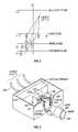
- FIG. 3shows a camera diagram with camera components
- FIG. 4Ashows a drawing of the preferred camera
- FIGS. 5 and 6shows more detailed drawings of the optical relays of the camera shown in FIG. 4A .
- FIG. 7is a schematic perspective view of the previously disclosed three-dimensional system, where one single lens is used with a three-aperture mask and a set of three separated cameras, each of which is associated with one aperture.
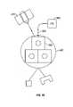
- FIG. 8A–8Bis a schematic perspective view of the present invention where 3 lens-aperture sets are used in combination with a set of three separated cameras, each of which is associated to one lens-aperture set.
- the drawingshows how the pattern defined by the geometry of the lens-aperture system (an equilateral triangle in this case) changes with the position in space of the corresponding source point.
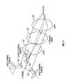
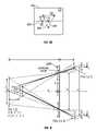
- FIG. 9is geometrical model of the present invention, using the 2-aperture arrangement for sake of clarity, and displaying all the parameters defining the optical principle of defocusing and upon which the present invention will be described in the following sections. The same parameters apply to a system with more than 2 lens-aperture systems.
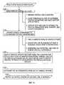
- FIG. 10is a flow diagram showing the sequence of program routines forming DE2PIV and used in the preprocessing of the combined images provided by a system with 3 lens-aperture sets.
- FIG 11is a flow diagram showing the sequence of program routines forming FINDPART and used in the image processing of the preprocessed images provided by DE2PIV, The program determines the three-dimesional coordinates of the scattering sources randomly distributed within a volume or on a surface.
- FIG. 12is a flow diagram showing the sequence of program routines forming FILTERPART and used in the processing of the results provided by FINDPART. Operations such as volume-of-interest, source characterization, 3D geometrical operations, are possible.
- FIG. 13is a flow diagram showing the sequence of program routines forming FINDFLOW and used in the processing of the results provided by FILTERPART.
- the programcalculates the 3D displacement of the scattering sources as a function of time, i.e. the 3D velocity.
- FIG. 14is a flow diagram showing the sequence of program routines forming FILTERFLOW and used in the processing of the results provided by FINDFLOW.
- the programvalidates the results and outputs the data to various standard formats. Every dataset of scattering sources is characterized by a 3D vector field comprising the 3D coordinates of every source, the 3D velocity.
- the inventorsrecognized that if all this information was obtained by a single camera, an image crowding problem could exist. This would limit the system to a lower density of number of images.
- the defocusing massesrequires multiple spatially-shaped holes. If there are n holes, then each scattering site has been imaged n times onto a single CCD. Hence, n times as many pixels are exposed. This means, however, that the capacity of the technique, i.e. the number of scattering sites that can be imaged, is correspondingly reduced by a factor of n.
- the present systemaddresses this and other issues.
- a first aspectaddresses the image crowding problem by exposing each of the multiple exposures using a separate camera portion.
- the camera systemcan be electronic or photographic based.
- the separate camera portionrequires that a whole camera imaging portion is used to obtain the images from each aperture at each time. This can use multiple separate cameras, a single camera with multiple parts, or a single camera used to obtain multiple exposures at different times.
- Another aspectobtains image information about the objects at a defocused image plane, i.e. one which is not in focus by the lens. Since the image plane is intentionally out of focus, there is less tradeoff regarding depth of field.
- the first embodimentuses image separation to expose each of the multiple exposures to its own electronic or photographic camera portion.
- the image separationcan be effected by color filters, by time coding, by spacial filters, or by using multiple independent cameras.
- the color filter embodimentis shown in FIG. 3 .
- a color camera and mask combinationis shown with three separate CCD cameras 300 , 304 (third CCD camera not shown in FIG. 3 ).
- Mask 342which includes an opaque aperture plate with three apertures formed therein.
- the aperturesare generally in the shape of a triangle.
- the lightpasses to a lens assembly 340 , which directs the light into the chamber that houses the camera.
- the color camerauses three monochrome CCD cameras, situated around a three way prism 310 which separates the incoming light according to its colors.
- a micro positioner assembly 312is provided to precisely adjust the cameras 300 , 304 such that each will view exactly the same area. Once those adjustments are made, the three cameras are locked into place so that any vibration affects each of them the same.
- Each cameraincludes an associated band filter.
- the filter 330is associated with CCD camera 300
- filter 332is associated with camera 304
- filter 334is associated with camera 304 .
- Each of these narrow band filterspasses only one of the colors that is passed by the coded apertures.
- the filtersare placed adjacent the prism output to correspond respectively to each of the primary colors, e.g. red, green and blue. Hence, the filters enable separating the different colors.
- This color camera assemblyis used in conjunction with an image lens assembly 340 and a aperture coded mask 342 .
- the system in FIG. 3shows the aperture coded mask having three mask portions in the form of an equilateral triangle.
- Each apertureis color coded according to the colors of the camera filters. This color coding can be done by, for example, using color filters on the apertures.
- the image from each aperturegoes to a separate one of the cameras 304 , 300 .
- the output from the camerais processed by the CCD electronics 350 and coupled to output cables shown as 352 .
- These three valuesare processed using a conventional processing software. The three values can be compensated separately.
- a second embodimentseparates the images from the different apertures using rapid sequential imaging.
- An embodimentis shown in FIG. 4 .
- a sceneis imaged through a mask 400 that includes multiple apertures.
- Each aperturehas an associated selective blocking means 402 .
- the blocking meansis a device that either allows light to pass through the aperture or blocks light from passing through the aperture under control of an applied control signal 404 from a control element 406 .
- the aperture blocking means 402can be a mechanical blocker e.g. a mechanical shutter, solid state optics, such as a liquid crystal which is selectively allowed to pass light, or a digital mirror which selectively reflects the light to the aperture or the like.
- Light from the scattering sitesis allowed to pass through each aperture at a separate time, under control of the controller 406 .
- the passed lightis sent to a single camera 430 that produces an image indicative of the passed light. Three different images are obtained at three different times. Each image is based on passage of the light through a different aperture.
- a purely mechanical meanscan be provided to pass light through only a single aperture by rotating the blocking element such that the blocking element is associated with different apertures at different times and hence provides different illuminations at different times.
- each of the corresponding camerasis exposed only when the corresponding aperture is allowed to receive light.
- the system shown in FIG. 4Ashows a CCD camera assembly 430 receiving the light from the various apertures.
- FIG. 5shows a preferred configuration of a spatially coded camera.
- the systemincludes a focusing lens assembly 500 , 504 , with an aperture system 506 between the two portions of the focusing lens 500 , 504 .
- An exploded view of the componentsis shown in FIG. 6 .
- Each of the prisms e.g. 510 and 514is directly located behind each aperture orifice.
- a three CW camera 520views the three images through the three aperture orifices, thereby providing three simultaneous views of the image.
- the lenses within the focusing lens assembly 500 , 504direct the scattered light from the scene through each of the three orifices at 120° angles with each other. The light is then collected through the aperture orifices and directed to the separate CCD cameras. Each of the images on each of the three cameras is recorded simultaneously and then processed to provide three dimensional spacial locations of the points on the scene.
- An alternative, but less preferred embodimentuses three separate cameras, in place of the one camera described above.
- the system as described and shown hereinincludes several advantages.
- the systemallows superior camera alignment as compared with other competing images such as stereoscopic techniques.
- This systemis also based on a defocusing technique as compared with stereoscopic techniques that require that the camera be focused on the area of interest.
- This systemhas significant advantages since it need not be focused on the area of interest, and therefore has fewer problems with trade offs between aperture size and other characteristics. (here)
- FIG. 7shows a composite and changed version of this 3D camera using one single large lens 700 with a mask 710 with 3 apertures.
- This solutionmay also require a lens assembly 720 , where F# ⁇ 1 (where F# is defined as f/d, where f is the lens' focal length, and d is the diameter of the lens).
- F#is defined as f/d, where f is the lens' focal length, and d is the diameter of the lens.
- This latter lensmay increase the cost of the assembly.
- the lensesmight need to be custom made.
- three prisms 730 , 732 , 734are used to redirect the light away from the optical axis of the camera. This may simplify the design.
- FIG. 8AAnother design is shown in FIG. 8A .
- the camera in FIG. 8Ais redesigned so that each photo sensor 804 has its own lens-aperture system 801 , 802 . Still, however, the global optical axis 804 of the camera is preserved and is unique. The system behaves as if we had replaced the original lens by a lens with infinite focal length.
- the use of small lenses 802 in front or behind the apertures 801may also improve the collection of light as to produce small images on the imaging sensors 805 , which allows the use of variable apertures and therefore allows to work in a wide range of lighting conditions.
- this lens assemblyallows for more accurate 3D imaging, as no complex optics are used, thus minimizing the optical imperfections, making the manufacturing easier and the system ruggedized for field applications where environmental concerns are an important factor.
- geometrical parameterscan be freely modified to match the specific requirements of the application, such as size of volume, depth resolution, etc
- FIGS. 8A and 8Bshows. how a point A placed on the reference plane 803 is imaged as one unique image 807 on the combined imaged 806 . Points B and C placed in between the lens-aperture plane and the reference plane will image as equilateral triangles 808 and 809 , respectively. This is due to the fact that the 3 imaging sensors were arranged to form an equilateral triangle, thereby resulting in the equilateral triangles shown by 808 and 809 . The size and the centroid of such triangles are directly related to the depth and plane location of the corresponding source point, respectively.
- This present embodimentallows for the 3 separate sensor/lens assemblies to be movable while maintaining the same geometric shape. For example, if the 3 sensor/lens sets are arranged so that they outline an equilateral triangle of a certain size, the 3 sensor/lens assemblies can be moved, thus allowing for visualizing smaller or larger volumes, in a manner that will preserve the equilateral triangle in their outline. Furthermore, the lens/pinhole assembly will be interchangeable to allow for imaging of various volume sizes. Such features will also allow the user to vary the working distance at their convenience.
- the choice of an equilateral triangle as the matching pattern, or equivalently of the number of apertures/imaging sensors (with a minimum of two),is arbitrary and is determined based on the needs of the user. It is also emphasized that the shape of the apertures is arbitrary and should only be defined by the efficiency in the collection of light and image processing. Furthermore, these apertures can be equipped with any type of light filters that would enhance any given features of the scene, such as the color. It is furthermore understood that the size of such apertures can be varied according to the light conditions, by means of any type of mechanical or electro-optical shuttering system. Finally, it is emphasized that the photo sensors can be of any sort of technology (CCD, CMOS, photographic plates, holographic plates . . .
- an off-the-shelf systemmoving cameras, analog or digital, high speed or standard frame rate, color or monochrome.
- This variety of implementationscan be combined to map features like the color of the measured points (for example in the case of measuring a live face), their size, density, etc.
- FIG. 9illustrates a 2 lens-aperture set.
- a simplified geometric model of a two-aperture defocusing optical arrangementis represented in FIG 3 .
- the interrogation domainis defined by a cube of side a.
- the back face of this cubeis on the reference plane, which is placed at a distance L from the lens plane.
- the image planeis materialized by a photo sensor (e.g. CCD) of height h.
- dbe the distance between apertures, f the focal length of the converging lens and l the distance from the lens to the image plane.
- the physical spaceis attached to a coordinate system originating in the lens plane, with the Z-axis on the optical axis of the system.
- Coordinates in the physical spaceare designated (X,Y,Z).
- the coordinates of a pixel on the imaging sensorare given by the pair (x, y).
- Point P(X,Y,Z)represents a light scattering source.
- FIG. 9shows a geometric diagram of the aperture mask.
- step 1000defines reading in three images from the three CCD cameras of any of the previous embodiments.
- preprocessing parametersmay be set up which may be used for noise processing, and background image removal.
- Particle peaksare identified at 1020 . These particle peaks may be identified by locally identifying peaks, building a particle around each peak, and then accounting for particle overlap. In this way, preprocessed peaks are obtained at 1030 , with the particle peaks being highlighted.
- a particleis built around the peaks, using the minimum and maximum particle size.
- a slope thresholdis used to determine the particle boundaries, and to build support sets around the pixels. These support sets are used to optimize the particle parameters such as maximum, intensity, size and center coordinates.
- the particle coordinatesare “dewarped”. This is done by using a calibration image of a known pattern. Distortions are determined by what is acquired as compared with what is known. The warped file is then output. The warping may thus accommodate for nonlinear imaging.
- particle triplets per pointare identified. This may be done using the conditions that triplets must form an inverted equilateral triangle.
- Each of the particle exposures on the CCD'smay be used to identify particles to accommodate for particle exposure overlap.
- the three-dimensional coordinatesare obtained from the size of the triangle pattern, and the 3-D particle spacing is output at 1140 based on location.
- the thus obtained resultsare further processed at 1200 identify the volume of interest, to translate the data set, and to rotate the data set.
- a radiusis determined at 1210 based on intensity as input from the calibration data set and the scattering formulation.
- the size related terms determined at 1220such as size histograms and void fraction.
- an output particle data fieldis obtained within the constraints given in the input parameter file.
- flow window lattice informationis set up to specify Voxel size and Voxel spacing.
- the velocityis calculated in 3-D space at 1310 . This may be done once or twice.
- the second voxelmay be locally shifted. This may be used to detect outliers and reinterpret those values. In general, this uses three-dimensional correlation of particles with in the Voxel. The correlation is not done by pixels, but rather by particle location and size.
- the resultsare output at 1320 as components of velocity within the spatial P 2 .
- the input parameters at 1400may include a region of interest, velocities of interest, and outlier correction.
- the velocity datamay be output into various formats at 1410 .
Landscapes
- Engineering & Computer Science (AREA)
- Multimedia (AREA)
- Signal Processing (AREA)
- Physics & Mathematics (AREA)
- General Physics & Mathematics (AREA)
- Length Measuring Devices By Optical Means (AREA)
Abstract
Description
Z=1/((1/L)+Kb) (1)
where
K=(L−f)/(fdL) (2)
X=(−x0Z(L−f))/(fL) (3)
Y=(−y0Z(L−f))/(fL) (4)
b=1/K((1/Z)−(1/L)) (5)
Claims (4)
Priority Applications (5)
| Application Number | Priority Date | Filing Date | Title |
|---|---|---|---|
| US09/935,215US7006132B2 (en) | 1998-02-25 | 2001-08-21 | Aperture coded camera for three dimensional imaging |
| EP02768657AEP1428071A4 (en) | 2001-08-21 | 2002-08-21 | APERTURE-CODED CAMERA FOR THREE-DIMENSIONAL IMAGING |
| PCT/US2002/026728WO2003017000A1 (en) | 2001-08-21 | 2002-08-21 | Aperture coded camera for three dimensional imaging |
| US11/365,970US7612869B2 (en) | 1998-02-25 | 2006-02-28 | Aperture coded camera for three dimensional imaging |
| US11/522,500US7612870B2 (en) | 1998-02-25 | 2006-09-14 | Single-lens aperture-coded camera for three dimensional imaging in small volumes |
Applications Claiming Priority (3)
| Application Number | Priority Date | Filing Date | Title |
|---|---|---|---|
| US7875098P | 1998-02-25 | 1998-02-25 | |
| US09/258,160US6278847B1 (en) | 1998-02-25 | 1999-02-25 | Aperture coded camera for three dimensional imaging |
| US09/935,215US7006132B2 (en) | 1998-02-25 | 2001-08-21 | Aperture coded camera for three dimensional imaging |
Related Parent Applications (1)
| Application Number | Title | Priority Date | Filing Date |
|---|---|---|---|
| US09/258,160Continuation-In-PartUS6278847B1 (en) | 1998-02-25 | 1999-02-25 | Aperture coded camera for three dimensional imaging |
Related Child Applications (1)
| Application Number | Title | Priority Date | Filing Date |
|---|---|---|---|
| US11/365,970ContinuationUS7612869B2 (en) | 1998-02-25 | 2006-02-28 | Aperture coded camera for three dimensional imaging |
Publications (2)
| Publication Number | Publication Date |
|---|---|
| US20020149691A1 US20020149691A1 (en) | 2002-10-17 |
| US7006132B2true US7006132B2 (en) | 2006-02-28 |
Family
ID=25466724
Family Applications (2)
| Application Number | Title | Priority Date | Filing Date |
|---|---|---|---|
| US09/935,215Expired - LifetimeUS7006132B2 (en) | 1998-02-25 | 2001-08-21 | Aperture coded camera for three dimensional imaging |
| US11/365,970Expired - Fee RelatedUS7612869B2 (en) | 1998-02-25 | 2006-02-28 | Aperture coded camera for three dimensional imaging |
Family Applications After (1)
| Application Number | Title | Priority Date | Filing Date |
|---|---|---|---|
| US11/365,970Expired - Fee RelatedUS7612869B2 (en) | 1998-02-25 | 2006-02-28 | Aperture coded camera for three dimensional imaging |
Country Status (3)
| Country | Link |
|---|---|
| US (2) | US7006132B2 (en) |
| EP (1) | EP1428071A4 (en) |
| WO (1) | WO2003017000A1 (en) |
Cited By (79)
| Publication number | Priority date | Publication date | Assignee | Title |
|---|---|---|---|---|
| US20040061774A1 (en)* | 2002-04-10 | 2004-04-01 | Wachtel Robert A. | Digital imaging system using overlapping images to formulate a seamless composite image and implemented using either a digital imaging sensor array |
| US20050228838A1 (en)* | 2003-04-10 | 2005-10-13 | Stetson Karl A | Processing technique for digital speckle photogrammetry |
| US20050275494A1 (en)* | 2004-05-25 | 2005-12-15 | Morteza Gharib | In-line actuator for electromagnetic operation |
| US20060196642A1 (en)* | 2004-12-28 | 2006-09-07 | Morteza Gharib | Fluidic pump for heat management |
| US20060209193A1 (en)* | 1998-02-25 | 2006-09-21 | Francisco Pereira | Aperture coded camera for three dimensional imaging |
| US20060215038A1 (en)* | 2001-05-04 | 2006-09-28 | Gruber Michael A | Large format camera systems |
| US20060216173A1 (en)* | 2005-03-25 | 2006-09-28 | Arash Kheradvar | Helically actuated positive-displacement pump and method |
| US20070038016A1 (en)* | 2005-01-10 | 2007-02-15 | Morteza Gharib | Impedance pump used in bypass grafts |
| US20070177997A1 (en)* | 2006-01-06 | 2007-08-02 | Morteza Gharib | Resonant Multilayered Impedance Pump |
| US20070179265A1 (en)* | 2005-09-21 | 2007-08-02 | Thomas Albers | Polymers for use in cleaning compositions |
| US20070181686A1 (en)* | 2005-10-16 | 2007-08-09 | Mediapod Llc | Apparatus, system and method for increasing quality of digital image capture |
| US20070188769A1 (en)* | 2006-02-13 | 2007-08-16 | Janos Rohaly | Three-channel camera systems with collinear apertures |
| US20070188601A1 (en)* | 2006-02-13 | 2007-08-16 | Janos Rohaly | Three-channel camera systems with non-collinear apertures |
| US20070195162A1 (en)* | 1998-02-25 | 2007-08-23 | Graff Emilio C | Single-lens aperture-coded camera for three dimensional imaging in small volumes |
| US20070199700A1 (en)* | 2006-02-27 | 2007-08-30 | Grant Hocking | Enhanced hydrocarbon recovery by in situ combustion of oil sand formations |
| US20080013943A1 (en)* | 2006-02-13 | 2008-01-17 | Janos Rohaly | Monocular three-dimensional imaging |
| WO2008091639A2 (en) | 2007-01-22 | 2008-07-31 | California Institute Of Technology | Method for quantitative 3-d imaging |
| US20080259354A1 (en)* | 2007-04-23 | 2008-10-23 | Morteza Gharib | Single-lens, single-aperture, single-sensor 3-D imaging device |
| US20090020714A1 (en)* | 2006-02-06 | 2009-01-22 | Qinetiq Limited | Imaging system |
| US20090022410A1 (en)* | 2006-02-06 | 2009-01-22 | Qinetiq Limited | Method and apparatus for coded aperture imaging |
| US20090052008A1 (en)* | 2006-02-06 | 2009-02-26 | Qinetiq Limited | Optical modulator |
| WO2009039117A1 (en)* | 2007-09-18 | 2009-03-26 | University Of Washington | Color-coded backlighted single camera three-dimensional defocusing particle image velocimetry system |
| US20090090868A1 (en)* | 2006-02-06 | 2009-04-09 | Qinetiq Limited | Coded aperture imaging method and system |
| US20090095912A1 (en)* | 2005-05-23 | 2009-04-16 | Slinger Christopher W | Coded aperture imaging system |
| US7605989B1 (en)* | 2008-07-22 | 2009-10-20 | Angstrom, Inc. | Compact auto-focus image taking lens system with a micromirror array lens and a lens-surfaced prism |
| US20090279737A1 (en)* | 2006-07-28 | 2009-11-12 | Qinetiq Limited | Processing method for coded aperture sensor |
| US20090295924A1 (en)* | 2002-08-28 | 2009-12-03 | M7 Visual Intelligence, L.P. | Retinal concave array compound camera system |
| US20090295908A1 (en)* | 2008-01-22 | 2009-12-03 | Morteza Gharib | Method and device for high-resolution three-dimensional imaging which obtains camera pose using defocusing |
| US20100007718A1 (en)* | 2006-02-13 | 2010-01-14 | Rohaly Jr Janos | Monocular three-dimensional imaging |
| US20100235095A1 (en)* | 2002-09-20 | 2010-09-16 | M7 Visual Intelligence, L.P. | Self-calibrated, remote imaging and data processing system |
| US20110037832A1 (en)* | 2009-08-11 | 2011-02-17 | California Institute Of Technology | Defocusing Feature Matching System to Measure Camera Pose with Interchangeable Lens Cameras |
| US20110058740A1 (en)* | 2007-01-22 | 2011-03-10 | California Institute Of Technology | Method and system for fast three-dimensional imaging using defocusing and feature recognition |
| US20110074932A1 (en)* | 2009-08-27 | 2011-03-31 | California Institute Of Technology | Accurate 3D Object Reconstruction Using a Handheld Device with a Projected Light Pattern |
| USD644243S1 (en)* | 2007-06-23 | 2011-08-30 | Apple Inc. | Icon for a portion of a display screen |
| USD644242S1 (en)* | 2007-06-23 | 2011-08-30 | Apple Inc. | Icon for a portion of a display screen |
| US20110228895A1 (en)* | 2008-12-06 | 2011-09-22 | Qinetiq Limited | Optically diverse coded aperture imaging |
| US8035085B2 (en) | 2006-02-06 | 2011-10-11 | Qinetiq Limited | Coded aperture imaging system |
| RU2431876C2 (en)* | 2008-12-24 | 2011-10-20 | Корпорация "САМСУНГ ЭЛЕКТРОНИКС Ко., Лтд." | Three-dimensional image camera with photomodulator |
| US20110286007A1 (en)* | 2010-05-21 | 2011-11-24 | John Gregory Pangrazio | Dimensional Detection System and Associated Method |
| US8068680B2 (en) | 2006-02-06 | 2011-11-29 | Qinetiq Limited | Processing methods for coded aperture imaging |
| WO2012030357A1 (en) | 2010-09-03 | 2012-03-08 | Arges Imaging, Inc. | Three-dimensional imaging system |
| USD659159S1 (en)* | 2007-06-23 | 2012-05-08 | Apple Inc. | Icon for a portion of a display screen |
| US8593565B2 (en) | 2011-03-25 | 2013-11-26 | Gary S. Shuster | Simulated large aperture lens |
| US20140267844A1 (en)* | 2013-03-14 | 2014-09-18 | Kabushiki Kaisha Toshiba | Camera module |
| US8994822B2 (en) | 2002-08-28 | 2015-03-31 | Visual Intelligence Lp | Infrastructure mapping system and method |
| US9125655B2 (en) | 2010-07-16 | 2015-09-08 | California Institute Of Technology | Correction and optimization of wave reflection in blood vessels |
| USD772932S1 (en) | 2014-09-02 | 2016-11-29 | Apple Inc. | Display screen or portion thereof with icon |
| US9524021B2 (en) | 2012-01-05 | 2016-12-20 | California Institute Of Technology | Imaging surround system for touch-free display control |
| US9530213B2 (en) | 2013-01-02 | 2016-12-27 | California Institute Of Technology | Single-sensor system for extracting depth information from image blur |
| USD780805S1 (en) | 2012-06-05 | 2017-03-07 | Apple Inc. | Display screen or portion thereof with graphical user interface |
| USD781879S1 (en) | 2014-09-02 | 2017-03-21 | Apple Inc. | Display screen or portion thereof with animated graphical user interface |
| US9656009B2 (en) | 2007-07-11 | 2017-05-23 | California Institute Of Technology | Cardiac assist system using helical arrangement of contractile bands and helically-twisting cardiac assist device |
| USD788161S1 (en) | 2015-09-08 | 2017-05-30 | Apple Inc. | Display screen or portion thereof with graphical user interface |
| USD789385S1 (en) | 2014-09-03 | 2017-06-13 | Apple Inc. | Display screen or portion thereof with graphical user interface |
| USD796543S1 (en) | 2016-06-10 | 2017-09-05 | Apple Inc. | Display screen or portion thereof with graphical user interface |
| USD804526S1 (en) | 2015-03-06 | 2017-12-05 | Apple Inc. | Display screen or portion thereof with icon |
| USD804502S1 (en) | 2016-06-11 | 2017-12-05 | Apple Inc. | Display screen or portion thereof with graphical user interface |
| USD820300S1 (en) | 2016-06-11 | 2018-06-12 | Apple Inc. | Display screen or portion thereof with graphical user interface |
| USD841664S1 (en) | 2014-09-01 | 2019-02-26 | Apple Inc. | Display screen or portion thereof with a set of graphical user interfaces |
| USD880508S1 (en) | 2014-09-01 | 2020-04-07 | Apple Inc. | Display screen or portion thereof with graphical user interface |
| USD895672S1 (en) | 2018-03-15 | 2020-09-08 | Apple Inc. | Electronic device with animated graphical user interface |
| USD898040S1 (en) | 2014-09-02 | 2020-10-06 | Apple Inc. | Display screen or portion thereof with graphical user interface |
| USD905745S1 (en) | 2010-10-20 | 2020-12-22 | Apple Inc. | Display screen or portion thereof with icon |
| USD910686S1 (en) | 2018-08-30 | 2021-02-16 | Apple Inc. | Electronic device with graphical user interface |
| USD911386S1 (en) | 2013-10-22 | 2021-02-23 | Apple Inc. | Display screen or portion thereof with icon |
| USD914756S1 (en) | 2018-10-29 | 2021-03-30 | Apple Inc. | Electronic device with graphical user interface |
| USD916133S1 (en) | 2019-09-08 | 2021-04-13 | Apple Inc. | Electronic device with icon |
| USD938492S1 (en) | 2018-05-08 | 2021-12-14 | Apple Inc. | Electronic device with animated graphical user interface |
| USD942509S1 (en) | 2020-06-19 | 2022-02-01 | Apple Inc. | Display screen or portion thereof with graphical user interface |
| USD951287S1 (en) | 2020-06-19 | 2022-05-10 | Apple Inc. | Display screen or portion thereof with graphical user interface |
| USRE49105E1 (en) | 2002-09-20 | 2022-06-14 | Vi Technologies, Llc | Self-calibrated, remote imaging and data processing system |
| USD956812S1 (en) | 2013-06-09 | 2022-07-05 | Apple Inc. | Display screen or portion thereof with graphical user interface |
| US11406264B2 (en) | 2016-01-25 | 2022-08-09 | California Institute Of Technology | Non-invasive measurement of intraocular pressure |
| USD962244S1 (en) | 2018-10-28 | 2022-08-30 | Apple Inc. | Electronic device with graphical user interface |
| USD964425S1 (en) | 2019-05-31 | 2022-09-20 | Apple Inc. | Electronic device with graphical user interface |
| US11557042B2 (en) | 2018-06-12 | 2023-01-17 | King Abdullah University Of Science And Technology | Single-camera particle tracking system and method |
| USD994688S1 (en) | 2019-03-22 | 2023-08-08 | Apple Inc. | Electronic device with animated graphical user interface |
| USD1002671S1 (en) | 2017-09-29 | 2023-10-24 | Apple Inc. | Wearable device with graphical user interface |
| USD1009931S1 (en) | 2014-09-01 | 2024-01-02 | Apple Inc. | Display screen or portion thereof with graphical user interface |
Families Citing this family (56)
| Publication number | Priority date | Publication date | Assignee | Title |
|---|---|---|---|---|
| ATE325354T1 (en)* | 2003-07-02 | 2006-06-15 | Berner Fachhochschule Hochschu | METHOD AND DEVICE FOR IMAGING WITH CODED APERTURE |
| US7154613B2 (en)* | 2004-03-15 | 2006-12-26 | Northrop Grumman Corporation | Color coded light for automated shape measurement using photogrammetry |
| US20060175561A1 (en)* | 2005-02-09 | 2006-08-10 | Innovative Scientific Solutions, Inc. | Particle shadow velocimetry |
| CN100378574C (en)* | 2005-05-25 | 2008-04-02 | 中国科学院上海光学精密机械研究所 | Three-dimensional imaging method |
| JP2009500963A (en)* | 2005-07-06 | 2009-01-08 | メディアポッド リミテッド ライアビリティ カンパニー | System and method for capturing visual and non-visual data for multi-dimensional video display |
| ATE480106T1 (en)* | 2005-11-04 | 2010-09-15 | Koninkl Philips Electronics Nv | PLAYBACK OF IMAGE DATA FOR MULTIPLE VIEW DISPLAY |
| DE102006043445A1 (en)* | 2006-09-15 | 2008-03-27 | Mtu Aero Engines Gmbh | Apparatus and method for three-dimensional flow measurement |
| US8488129B2 (en)* | 2007-10-05 | 2013-07-16 | Artec Group, Inc. | Combined object capturing system and display device and associated method |
| US20100007660A1 (en)* | 2008-07-11 | 2010-01-14 | Arian Soroush Forouhar | Pattern inversion for improved resolution in 3D imaging |
| US9495751B2 (en)* | 2010-02-19 | 2016-11-15 | Dual Aperture International Co. Ltd. | Processing multi-aperture image data |
| US8330852B2 (en)* | 2010-04-30 | 2012-12-11 | Eastman Kodak Company | Range measurement using symmetric coded apertures |
| US8436912B2 (en)* | 2010-04-30 | 2013-05-07 | Intellectual Ventures Fund 83 Llc | Range measurement using multiple coded apertures |
| US20110267485A1 (en)* | 2010-04-30 | 2011-11-03 | Kane Paul J | Range measurement using a coded aperture |
| US8582820B2 (en) | 2010-09-24 | 2013-11-12 | Apple Inc. | Coded aperture camera with adaptive image processing |
| US20140152771A1 (en)* | 2012-12-01 | 2014-06-05 | Og Technologies, Inc. | Method and apparatus of profile measurement |
| US9568713B2 (en) | 2013-01-05 | 2017-02-14 | Light Labs Inc. | Methods and apparatus for using multiple optical chains in parallel to support separate color-capture |
| US9549127B2 (en) | 2013-10-18 | 2017-01-17 | Light Labs Inc. | Image capture control methods and apparatus |
| US9851527B2 (en) | 2013-10-18 | 2017-12-26 | Light Labs Inc. | Methods and apparatus for capturing and/or combining images |
| US9374514B2 (en) | 2013-10-18 | 2016-06-21 | The Lightco Inc. | Methods and apparatus relating to a camera including multiple optical chains |
| US9736365B2 (en) | 2013-10-26 | 2017-08-15 | Light Labs Inc. | Zoom related methods and apparatus |
| US9467627B2 (en) | 2013-10-26 | 2016-10-11 | The Lightco Inc. | Methods and apparatus for use with multiple optical chains |
| US9426365B2 (en) | 2013-11-01 | 2016-08-23 | The Lightco Inc. | Image stabilization related methods and apparatus |
| US9554031B2 (en) | 2013-12-31 | 2017-01-24 | Light Labs Inc. | Camera focusing related methods and apparatus |
| US20150244949A1 (en) | 2014-02-21 | 2015-08-27 | Rajiv Laroia | Illumination methods and apparatus |
| US9979878B2 (en) | 2014-02-21 | 2018-05-22 | Light Labs Inc. | Intuitive camera user interface methods and apparatus |
| JP6130805B2 (en)* | 2014-03-31 | 2017-05-17 | アズビル株式会社 | Distance measuring apparatus and method |
| US9678099B2 (en)* | 2014-04-24 | 2017-06-13 | Cubic Corporation | Athermalized optics for laser wind sensing |
| CN106575366A (en) | 2014-07-04 | 2017-04-19 | 光实验室股份有限公司 | Method and apparatus for detecting and/or indicating dirty lens condition |
| US10110794B2 (en) | 2014-07-09 | 2018-10-23 | Light Labs Inc. | Camera device including multiple optical chains and related methods |
| WO2016061565A1 (en) | 2014-10-17 | 2016-04-21 | The Lightco Inc. | Methods and apparatus for using a camera device to support multiple modes of operation |
| US10443984B2 (en) | 2014-11-17 | 2019-10-15 | Cubic Corporation | Low-cost rifle scope display adapter |
| US9791244B2 (en) | 2014-11-17 | 2017-10-17 | Cubic Corporation | Rifle scope targeting display adapter mount |
| US10274286B2 (en) | 2014-11-17 | 2019-04-30 | Cubic Corporation | Rifle scope targeting display adapter |
| WO2016100756A1 (en) | 2014-12-17 | 2016-06-23 | The Lightco Inc. | Methods and apparatus for implementing and using camera devices |
| US9544503B2 (en) | 2014-12-30 | 2017-01-10 | Light Labs Inc. | Exposure control methods and apparatus |
| US20160255323A1 (en) | 2015-02-26 | 2016-09-01 | Dual Aperture International Co. Ltd. | Multi-Aperture Depth Map Using Blur Kernels and Down-Sampling |
| US9824427B2 (en) | 2015-04-15 | 2017-11-21 | Light Labs Inc. | Methods and apparatus for generating a sharp image |
| US9857584B2 (en) | 2015-04-17 | 2018-01-02 | Light Labs Inc. | Camera device methods, apparatus and components |
| US10091447B2 (en) | 2015-04-17 | 2018-10-02 | Light Labs Inc. | Methods and apparatus for synchronizing readout of multiple image sensors |
| US10075651B2 (en) | 2015-04-17 | 2018-09-11 | Light Labs Inc. | Methods and apparatus for capturing images using multiple camera modules in an efficient manner |
| US9967535B2 (en) | 2015-04-17 | 2018-05-08 | Light Labs Inc. | Methods and apparatus for reducing noise in images |
| US9930233B2 (en) | 2015-04-22 | 2018-03-27 | Light Labs Inc. | Filter mounting methods and apparatus and related camera apparatus |
| US10129483B2 (en) | 2015-06-23 | 2018-11-13 | Light Labs Inc. | Methods and apparatus for implementing zoom using one or more moveable camera modules |
| US10491806B2 (en) | 2015-08-03 | 2019-11-26 | Light Labs Inc. | Camera device control related methods and apparatus |
| US10365480B2 (en) | 2015-08-27 | 2019-07-30 | Light Labs Inc. | Methods and apparatus for implementing and/or using camera devices with one or more light redirection devices |
| US9749549B2 (en) | 2015-10-06 | 2017-08-29 | Light Labs Inc. | Methods and apparatus for facilitating selective blurring of one or more image portions |
| US10003738B2 (en) | 2015-12-18 | 2018-06-19 | Light Labs Inc. | Methods and apparatus for detecting and/or indicating a blocked sensor or camera module |
| US10225445B2 (en) | 2015-12-18 | 2019-03-05 | Light Labs Inc. | Methods and apparatus for providing a camera lens or viewing point indicator |
| US10306218B2 (en) | 2016-03-22 | 2019-05-28 | Light Labs Inc. | Camera calibration apparatus and methods |
| US9948832B2 (en) | 2016-06-22 | 2018-04-17 | Light Labs Inc. | Methods and apparatus for synchronized image capture in a device including optical chains with different orientations |
| US10999569B2 (en) | 2016-12-22 | 2021-05-04 | Eva—Esthetic Visual Analytics Ltd. | Three-dimensional image reconstruction using multi-layer data acquisition |
| ES3024938T3 (en) | 2016-12-22 | 2025-06-05 | Cherry Imaging Ltd | Real-time tracking for three-dimensional imaging |
| US11402740B2 (en) | 2016-12-22 | 2022-08-02 | Cherry Imaging Ltd. | Real-time tracking for three-dimensional imaging |
| US11412204B2 (en) | 2016-12-22 | 2022-08-09 | Cherry Imaging Ltd. | Three-dimensional image reconstruction using multi-layer data acquisition |
| US10186051B2 (en) | 2017-05-11 | 2019-01-22 | Dantec Dynamics A/S | Method and system for calibrating a velocimetry system |
| KR102102291B1 (en)* | 2017-12-20 | 2020-04-21 | 주식회사 고영테크놀러지 | Optical tracking system and optical tracking method |
Citations (11)
| Publication number | Priority date | Publication date | Assignee | Title |
|---|---|---|---|---|
| US4830485A (en)* | 1987-11-23 | 1989-05-16 | General Electric Company | Coded aperture light detector for three dimensional camera |
| US5075561A (en) | 1989-08-24 | 1991-12-24 | National Research Council Of Canada/Conseil National De Recherches Du Canada | Three dimensional imaging device comprising a lens system for simultaneous measurement of a range of points on a target surface |
| US5168327A (en) | 1990-04-04 | 1992-12-01 | Mitsubishi Denki Kabushiki Kaisha | Imaging device |
| US5270795A (en) | 1992-08-11 | 1993-12-14 | National Research Council Of Canada/Conseil National De Rechereches Du Canada | Validation of optical ranging of a target surface in a cluttered environment |
| US5294971A (en)* | 1990-02-07 | 1994-03-15 | Leica Heerbrugg Ag | Wave front sensor |
| US5565914A (en)* | 1994-04-08 | 1996-10-15 | Motta; Ricardo J. | Detector with a non-uniform spatial sensitivity |
| US5990934A (en)* | 1995-04-28 | 1999-11-23 | Lucent Technologies, Inc. | Method and system for panoramic viewing |
| US6278847B1 (en)* | 1998-02-25 | 2001-08-21 | California Institute Of Technology | Aperture coded camera for three dimensional imaging |
| US6353227B1 (en)* | 1998-12-18 | 2002-03-05 | Izzie Boxen | Dynamic collimators |
| US6674463B1 (en)* | 1999-08-06 | 2004-01-06 | Deiter Just | Technique for autostereoscopic image, film and television acquisition and display by multi-aperture multiplexing |
| US6737652B2 (en)* | 2000-09-29 | 2004-05-18 | Massachusetts Institute Of Technology | Coded aperture imaging |
Family Cites Families (40)
| Publication number | Priority date | Publication date | Assignee | Title |
|---|---|---|---|---|
| US3589815A (en) | 1968-06-21 | 1971-06-29 | Information Dev Corp | Noncontact measuring probe |
| US3625618A (en) | 1969-10-23 | 1971-12-07 | Infrared Ind Inc | Optical contour device and method |
| US4247177A (en) | 1979-01-15 | 1981-01-27 | Marks Alvin M | 3D Multichrome filters for spectacle frames |
| US4299491A (en) | 1979-12-11 | 1981-11-10 | United Technologies Corporation | Noncontact optical gauging system |
| US4375921A (en) | 1980-03-13 | 1983-03-08 | Selective Electronic Co. Ab | Dimension measuring apparatus |
| US4473750A (en) | 1980-07-25 | 1984-09-25 | Hitachi, Ltd. | Three-dimensional shape measuring device |
| US4494874A (en) | 1981-07-07 | 1985-01-22 | Robotic Vision Systems, Inc. | Detection of three-dimensional information using a projected point or line of light |
| US4594001A (en) | 1981-07-07 | 1986-06-10 | Robotic Vision Systems, Inc. | Detection of three-dimensional information with a projected plane of light |
| US4532723A (en) | 1982-03-25 | 1985-08-06 | General Electric Company | Optical inspection system |
| US4645347A (en)* | 1985-04-30 | 1987-02-24 | Canadian Patents And Development Limited-Societe Canadienne Des Brevets Et D'exploitation Limitee | Three dimensional imaging device |
| US4729109A (en) | 1985-05-29 | 1988-03-01 | University Of Illinois | Method and apparatus for measuring the displacements of particle images for multiple exposure velocimetry |
| SE447848B (en) | 1985-06-14 | 1986-12-15 | Anders Bengtsson | INSTRUMENTS FOR SEATING SURFACE TOPOGRAPHY |
| US4988191A (en) | 1987-03-09 | 1991-01-29 | University Of Illinois | Electro-optical method and system for determining the direction of motion in double-exposure velocimetry by shifting an optical image field |
| US4983043A (en) | 1987-04-17 | 1991-01-08 | Industrial Technology Institute | High accuracy structured light profiler |
| US4919536A (en) | 1988-06-06 | 1990-04-24 | Northrop Corporation | System for measuring velocity field of fluid flow utilizing a laser-doppler spectral image converter |
| US4935635A (en) | 1988-12-09 | 1990-06-19 | Harra Dale G O | System for measuring objects in three dimensions |
| US4979815A (en) | 1989-02-17 | 1990-12-25 | Tsikos Constantine J | Laser range imaging system based on projective geometry |
| CA1316590C (en) | 1989-04-17 | 1993-04-20 | Marc Rioux | Three-dimensional imaging device |
| US5189493A (en) | 1990-11-02 | 1993-02-23 | Industrial Technology Institute | Moire contouring camera |
| US5110204A (en) | 1990-11-06 | 1992-05-05 | Trustees Of Princeton University | Velocity measurement by the vibrational tagging of diatomic molecules |
| DE4237440C1 (en) | 1992-11-06 | 1994-03-10 | Deutsche Forsch Luft Raumfahrt | Optical imaging system for three=dimensional flow determination - has light source for short time exposure, and stereoscopic video imaging unit with synchronous image shifting by two mirrors which rotate about common axis parallel to line joining entrance-aperture objective lenses |
| US5333044A (en) | 1992-11-24 | 1994-07-26 | The United States Of America As Represented By The Department Of Energy | Fluorescent image tracking velocimeter |
| US5383021A (en) | 1993-04-19 | 1995-01-17 | Mectron Engineering Company | Optical part inspection system |
| US5367378A (en) | 1993-06-01 | 1994-11-22 | Industrial Technology Institute | Highlighted panel inspection |
| US5475422A (en)* | 1993-06-21 | 1995-12-12 | Nippon Telegraph And Telephone Corporation | Method and apparatus for reconstructing three-dimensional objects |
| US5500737A (en) | 1993-07-21 | 1996-03-19 | General Electric Company | Method for measuring the contour of a surface |
| US5491642A (en) | 1993-12-03 | 1996-02-13 | United Technologies Corporation | CCD based particle image direction and zero velocity resolver |
| DE4408072C2 (en) | 1994-02-01 | 1997-11-20 | Deutsche Forsch Luft Raumfahrt | Use of an electronic high-speed camera in a method for determining flow velocities in a flow |
| US5661667A (en) | 1994-03-14 | 1997-08-26 | Virtek Vision Corp. | 3D imaging using a laser projector |
| DE4408540C1 (en) | 1994-03-14 | 1995-03-23 | Jenoptik Technologie Gmbh | Arrangement for optical autocorrelation |
| US5548419A (en) | 1994-06-20 | 1996-08-20 | University Of Illinois | Stereo multiplexed holographic particle image velocimeter |
| US5675407A (en) | 1995-03-02 | 1997-10-07 | Zheng Jason Geng | Color ranging method for high speed low-cost three dimensional surface profile measurement |
| US5646733A (en) | 1996-01-29 | 1997-07-08 | Medar, Inc. | Scanning phase measuring method and system for an object at a vision station |
| US5850485A (en) | 1996-07-03 | 1998-12-15 | Massachusetts Institute Of Technology | Sparse array image correlation |
| US5905568A (en) | 1997-12-15 | 1999-05-18 | The United States Of America As Represented By The Administrator Of The National Aeronautics And Space Administration | Stereo imaging velocimetry |
| JPH11183797A (en) | 1997-12-19 | 1999-07-09 | Nikon Corp | Short distance correction lens |
| US7006132B2 (en) | 1998-02-25 | 2006-02-28 | California Institute Of Technology | Aperture coded camera for three dimensional imaging |
| US6252623B1 (en) | 1998-05-15 | 2001-06-26 | 3Dmetrics, Incorporated | Three dimensional imaging system |
| DE19836886C2 (en)* | 1998-08-14 | 2002-01-03 | Dieter Just | Process for autostereoscopic image generation and display |
| US6603535B1 (en)* | 2002-08-30 | 2003-08-05 | The United States Of America As Represented By The Administrator Of The National Aeronautics And Space Administration | Stereo imaging velocimetry system and method |
- 2001
- 2001-08-21USUS09/935,215patent/US7006132B2/ennot_activeExpired - Lifetime
- 2002
- 2002-08-21EPEP02768657Apatent/EP1428071A4/ennot_activeCeased
- 2002-08-21WOPCT/US2002/026728patent/WO2003017000A1/ennot_activeApplication Discontinuation
- 2006
- 2006-02-28USUS11/365,970patent/US7612869B2/ennot_activeExpired - Fee Related
Patent Citations (11)
| Publication number | Priority date | Publication date | Assignee | Title |
|---|---|---|---|---|
| US4830485A (en)* | 1987-11-23 | 1989-05-16 | General Electric Company | Coded aperture light detector for three dimensional camera |
| US5075561A (en) | 1989-08-24 | 1991-12-24 | National Research Council Of Canada/Conseil National De Recherches Du Canada | Three dimensional imaging device comprising a lens system for simultaneous measurement of a range of points on a target surface |
| US5294971A (en)* | 1990-02-07 | 1994-03-15 | Leica Heerbrugg Ag | Wave front sensor |
| US5168327A (en) | 1990-04-04 | 1992-12-01 | Mitsubishi Denki Kabushiki Kaisha | Imaging device |
| US5270795A (en) | 1992-08-11 | 1993-12-14 | National Research Council Of Canada/Conseil National De Rechereches Du Canada | Validation of optical ranging of a target surface in a cluttered environment |
| US5565914A (en)* | 1994-04-08 | 1996-10-15 | Motta; Ricardo J. | Detector with a non-uniform spatial sensitivity |
| US5990934A (en)* | 1995-04-28 | 1999-11-23 | Lucent Technologies, Inc. | Method and system for panoramic viewing |
| US6278847B1 (en)* | 1998-02-25 | 2001-08-21 | California Institute Of Technology | Aperture coded camera for three dimensional imaging |
| US6353227B1 (en)* | 1998-12-18 | 2002-03-05 | Izzie Boxen | Dynamic collimators |
| US6674463B1 (en)* | 1999-08-06 | 2004-01-06 | Deiter Just | Technique for autostereoscopic image, film and television acquisition and display by multi-aperture multiplexing |
| US6737652B2 (en)* | 2000-09-29 | 2004-05-18 | Massachusetts Institute Of Technology | Coded aperture imaging |
Cited By (184)
| Publication number | Priority date | Publication date | Assignee | Title |
|---|---|---|---|---|
| US20060209193A1 (en)* | 1998-02-25 | 2006-09-21 | Francisco Pereira | Aperture coded camera for three dimensional imaging |
| US7612870B2 (en) | 1998-02-25 | 2009-11-03 | California Institute Of Technology | Single-lens aperture-coded camera for three dimensional imaging in small volumes |
| US7612869B2 (en) | 1998-02-25 | 2009-11-03 | California Institute Of Technology | Aperture coded camera for three dimensional imaging |
| US20070195162A1 (en)* | 1998-02-25 | 2007-08-23 | Graff Emilio C | Single-lens aperture-coded camera for three dimensional imaging in small volumes |
| US7339614B2 (en)* | 2001-05-04 | 2008-03-04 | Microsoft Corporation | Large format camera system with multiple coplanar focusing systems |
| US20060215038A1 (en)* | 2001-05-04 | 2006-09-28 | Gruber Michael A | Large format camera systems |
| US20040061774A1 (en)* | 2002-04-10 | 2004-04-01 | Wachtel Robert A. | Digital imaging system using overlapping images to formulate a seamless composite image and implemented using either a digital imaging sensor array |
| US7215364B2 (en)* | 2002-04-10 | 2007-05-08 | Panx Imaging, Inc. | Digital imaging system using overlapping images to formulate a seamless composite image and implemented using either a digital imaging sensor array |
| US20090295924A1 (en)* | 2002-08-28 | 2009-12-03 | M7 Visual Intelligence, L.P. | Retinal concave array compound camera system |
| US8896695B2 (en) | 2002-08-28 | 2014-11-25 | Visual Intelligence Lp | Retinal concave array compound camera system |
| US8994822B2 (en) | 2002-08-28 | 2015-03-31 | Visual Intelligence Lp | Infrastructure mapping system and method |
| USRE49105E1 (en) | 2002-09-20 | 2022-06-14 | Vi Technologies, Llc | Self-calibrated, remote imaging and data processing system |
| US9389298B2 (en) | 2002-09-20 | 2016-07-12 | Visual Intelligence Lp | Self-calibrated, remote imaging and data processing system |
| US9797980B2 (en) | 2002-09-20 | 2017-10-24 | Visual Intelligence Lp | Self-calibrated, remote imaging and data processing system |
| US20100235095A1 (en)* | 2002-09-20 | 2010-09-16 | M7 Visual Intelligence, L.P. | Self-calibrated, remote imaging and data processing system |
| US8483960B2 (en) | 2002-09-20 | 2013-07-09 | Visual Intelligence, LP | Self-calibrated, remote imaging and data processing system |
| US20050228838A1 (en)* | 2003-04-10 | 2005-10-13 | Stetson Karl A | Processing technique for digital speckle photogrammetry |
| US8197234B2 (en) | 2004-05-25 | 2012-06-12 | California Institute Of Technology | In-line actuator for electromagnetic operation |
| US20050275494A1 (en)* | 2004-05-25 | 2005-12-15 | Morteza Gharib | In-line actuator for electromagnetic operation |
| US7398818B2 (en) | 2004-12-28 | 2008-07-15 | California Institute Of Technology | Fluidic pump for heat management |
| US20060196642A1 (en)* | 2004-12-28 | 2006-09-07 | Morteza Gharib | Fluidic pump for heat management |
| US20100241213A1 (en)* | 2005-01-10 | 2010-09-23 | California Institute Of Technology | Impedance Pump Used in Bypass Grafts |
| US7749152B2 (en) | 2005-01-10 | 2010-07-06 | California Institute Of Technology | Impedance pump used in bypass grafts |
| US20070038016A1 (en)* | 2005-01-10 | 2007-02-15 | Morteza Gharib | Impedance pump used in bypass grafts |
| US8794937B2 (en) | 2005-03-25 | 2014-08-05 | California Institute Of Technology | Helically actuated positive-displacement pump and method |
| US20060216173A1 (en)* | 2005-03-25 | 2006-09-28 | Arash Kheradvar | Helically actuated positive-displacement pump and method |
| US7883325B2 (en) | 2005-03-25 | 2011-02-08 | Arash Kheradvar | Helically actuated positive-displacement pump and method |
| US20090095912A1 (en)* | 2005-05-23 | 2009-04-16 | Slinger Christopher W | Coded aperture imaging system |
| US7888626B2 (en) | 2005-05-23 | 2011-02-15 | Qinetiq Limited | Coded aperture imaging system having adjustable imaging performance with a reconfigurable coded aperture mask |
| US20070179265A1 (en)* | 2005-09-21 | 2007-08-02 | Thomas Albers | Polymers for use in cleaning compositions |
| US7864211B2 (en) | 2005-10-16 | 2011-01-04 | Mowry Craig P | Apparatus, system and method for increasing quality of digital image capture |
| US20070181686A1 (en)* | 2005-10-16 | 2007-08-09 | Mediapod Llc | Apparatus, system and method for increasing quality of digital image capture |
| US20070177997A1 (en)* | 2006-01-06 | 2007-08-02 | Morteza Gharib | Resonant Multilayered Impedance Pump |
| US8092365B2 (en) | 2006-01-06 | 2012-01-10 | California Institute Of Technology | Resonant multilayered impedance pump |
| US8017899B2 (en) | 2006-02-06 | 2011-09-13 | Qinetiq Limited | Coded aperture imaging using successive imaging of a reference object at different positions |
| US8035085B2 (en) | 2006-02-06 | 2011-10-11 | Qinetiq Limited | Coded aperture imaging system |
| US20090020714A1 (en)* | 2006-02-06 | 2009-01-22 | Qinetiq Limited | Imaging system |
| US7969639B2 (en) | 2006-02-06 | 2011-06-28 | Qinetiq Limited | Optical modulator |
| US7923677B2 (en) | 2006-02-06 | 2011-04-12 | Qinetiq Limited | Coded aperture imager comprising a coded diffractive mask |
| US20090090868A1 (en)* | 2006-02-06 | 2009-04-09 | Qinetiq Limited | Coded aperture imaging method and system |
| US8073268B2 (en) | 2006-02-06 | 2011-12-06 | Qinetiq Limited | Method and apparatus for coded aperture imaging |
| US8068680B2 (en) | 2006-02-06 | 2011-11-29 | Qinetiq Limited | Processing methods for coded aperture imaging |
| US20090052008A1 (en)* | 2006-02-06 | 2009-02-26 | Qinetiq Limited | Optical modulator |
| US20090022410A1 (en)* | 2006-02-06 | 2009-01-22 | Qinetiq Limited | Method and apparatus for coded aperture imaging |
| US20070188601A1 (en)* | 2006-02-13 | 2007-08-16 | Janos Rohaly | Three-channel camera systems with non-collinear apertures |
| US8675291B2 (en) | 2006-02-13 | 2014-03-18 | 3M Innovative Properties Company | Monocular three-dimensional imaging |
| US20100007718A1 (en)* | 2006-02-13 | 2010-01-14 | Rohaly Jr Janos | Monocular three-dimensional imaging |
| US7646550B2 (en) | 2006-02-13 | 2010-01-12 | 3M Innovative Properties Company | Three-channel camera systems with collinear apertures |
| US7819591B2 (en) | 2006-02-13 | 2010-10-26 | 3M Innovative Properties Company | Monocular three-dimensional imaging |
| US20070188769A1 (en)* | 2006-02-13 | 2007-08-16 | Janos Rohaly | Three-channel camera systems with collinear apertures |
| US20080013943A1 (en)* | 2006-02-13 | 2008-01-17 | Janos Rohaly | Monocular three-dimensional imaging |
| US7746568B2 (en) | 2006-02-13 | 2010-06-29 | 3M Innovative Properties Company | Three-channel camera systems with non-collinear apertures |
| US8675290B2 (en) | 2006-02-13 | 2014-03-18 | 3M Innovative Properties Company | Monocular three-dimensional imaging |
| US20080204900A1 (en)* | 2006-02-13 | 2008-08-28 | 3M Innovative Properties Company | Three-channel camera systems with non-collinear apertures |
| US7372642B2 (en) | 2006-02-13 | 2008-05-13 | 3M Innovative Properties Company | Three-channel camera systems with non-collinear apertures |
| US20070199700A1 (en)* | 2006-02-27 | 2007-08-30 | Grant Hocking | Enhanced hydrocarbon recovery by in situ combustion of oil sand formations |
| US8229165B2 (en) | 2006-07-28 | 2012-07-24 | Qinetiq Limited | Processing method for coded aperture sensor |
| US20090279737A1 (en)* | 2006-07-28 | 2009-11-12 | Qinetiq Limited | Processing method for coded aperture sensor |
| US7826067B2 (en) | 2007-01-22 | 2010-11-02 | California Institute Of Technology | Method and apparatus for quantitative 3-D imaging |
| US20080239316A1 (en)* | 2007-01-22 | 2008-10-02 | Morteza Gharib | Method and apparatus for quantitative 3-D imaging |
| US20110058740A1 (en)* | 2007-01-22 | 2011-03-10 | California Institute Of Technology | Method and system for fast three-dimensional imaging using defocusing and feature recognition |
| US20080278804A1 (en)* | 2007-01-22 | 2008-11-13 | Morteza Gharib | Method and apparatus for quantitative 3-D imaging |
| US8576381B2 (en) | 2007-01-22 | 2013-11-05 | California Institute Of Technology | Method and apparatus for quantitative 3-D imaging |
| US8456645B2 (en) | 2007-01-22 | 2013-06-04 | California Institute Of Technology | Method and system for fast three-dimensional imaging using defocusing and feature recognition |
| WO2008091639A3 (en)* | 2007-01-22 | 2009-05-07 | California Inst Of Techn | Method for quantitative 3-d imaging |
| US9219907B2 (en) | 2007-01-22 | 2015-12-22 | California Institute Of Technology | Method and apparatus for quantitative 3-D imaging |
| WO2008091639A2 (en) | 2007-01-22 | 2008-07-31 | California Institute Of Technology | Method for quantitative 3-d imaging |
| US8089635B2 (en) | 2007-01-22 | 2012-01-03 | California Institute Of Technology | Method and system for fast three-dimensional imaging using defocusing and feature recognition |
| US20080259354A1 (en)* | 2007-04-23 | 2008-10-23 | Morteza Gharib | Single-lens, single-aperture, single-sensor 3-D imaging device |
| US7916309B2 (en) | 2007-04-23 | 2011-03-29 | California Institute Of Technology | Single-lens, single-aperture, single-sensor 3-D imaging device |
| AU2008244494B2 (en)* | 2007-04-23 | 2010-10-21 | California Institute Of Technology | Single-lens 3-D imaging device using a polarization-coded aperture mask combined with a polarization-sensitive sensor |
| US8619126B2 (en) | 2007-04-23 | 2013-12-31 | California Institute Of Technology | Single-lens, single-sensor 3-D imaging device with a central aperture for obtaining camera position |
| US9100641B2 (en) | 2007-04-23 | 2015-08-04 | California Institute Of Technology | Single-lens, single-sensor 3-D imaging device with a central aperture for obtaining camera position |
| US7894078B2 (en)* | 2007-04-23 | 2011-02-22 | California Institute Of Technology | Single-lens 3-D imaging device using a polarization-coded aperture masks combined with a polarization-sensitive sensor |
| US20110170100A1 (en)* | 2007-04-23 | 2011-07-14 | California Institute Of Technology | Single-Lens 3-D Imaging Device Using Polarization Coded Aperture Masks Combined with Polarization Sensitive Sensor |
| US20110193942A1 (en)* | 2007-04-23 | 2011-08-11 | California Institute Of Technology | Single-Lens, Single-Aperture, Single-Sensor 3-D Imaging Device |
| US20080278570A1 (en)* | 2007-04-23 | 2008-11-13 | Morteza Gharib | Single-lens, single-sensor 3-D imaging device with a central aperture for obtaining camera position |
| US9736463B2 (en) | 2007-04-23 | 2017-08-15 | California Institute Of Technology | Single-lens, single-sensor 3-D imaging device with a central aperture for obtaining camera position |
| US20080285034A1 (en)* | 2007-04-23 | 2008-11-20 | Morteza Gharib | Single-lens 3-D imaging device using a polarization-coded aperture maks combined with a polarization-sensitive sensor |
| US8259306B2 (en) | 2007-04-23 | 2012-09-04 | California Institute Of Technology | Single-lens, single-aperture, single-sensor 3-D imaging device |
| US20080278572A1 (en)* | 2007-04-23 | 2008-11-13 | Morteza Gharib | Aperture system with spatially-biased aperture shapes and positions (SBPSP) for static and dynamic 3-D defocusing-based imaging |
| US8472032B2 (en) | 2007-04-23 | 2013-06-25 | California Institute Of Technology | Single-lens 3-D imaging device using polarization coded aperture masks combined with polarization sensitive sensor |
| USD644243S1 (en)* | 2007-06-23 | 2011-08-30 | Apple Inc. | Icon for a portion of a display screen |
| USD659159S1 (en)* | 2007-06-23 | 2012-05-08 | Apple Inc. | Icon for a portion of a display screen |
| USD644242S1 (en)* | 2007-06-23 | 2011-08-30 | Apple Inc. | Icon for a portion of a display screen |
| US9656009B2 (en) | 2007-07-11 | 2017-05-23 | California Institute Of Technology | Cardiac assist system using helical arrangement of contractile bands and helically-twisting cardiac assist device |
| WO2009039117A1 (en)* | 2007-09-18 | 2009-03-26 | University Of Washington | Color-coded backlighted single camera three-dimensional defocusing particle image velocimetry system |
| US8638358B2 (en)* | 2007-09-18 | 2014-01-28 | University Of Washington | Color-coded backlighted single camera three-dimensional defocusing particle image velocimetry system |
| US20110025826A1 (en)* | 2007-09-18 | 2011-02-03 | University Of Washington | Color-coded backlighted single camera three-dimensional defocusing particle image velocimetry system |
| US8514268B2 (en)* | 2008-01-22 | 2013-08-20 | California Institute Of Technology | Method and device for high-resolution three-dimensional imaging which obtains camera pose using defocusing |
| US20090295908A1 (en)* | 2008-01-22 | 2009-12-03 | Morteza Gharib | Method and device for high-resolution three-dimensional imaging which obtains camera pose using defocusing |
| US7605989B1 (en)* | 2008-07-22 | 2009-10-20 | Angstrom, Inc. | Compact auto-focus image taking lens system with a micromirror array lens and a lens-surfaced prism |
| US20140022350A1 (en)* | 2008-08-27 | 2014-01-23 | California Institute Of Technology | Method and device for high-resolution imaging which obtains camera pose using defocusing |
| US9247235B2 (en)* | 2008-08-27 | 2016-01-26 | California Institute Of Technology | Method and device for high-resolution imaging which obtains camera pose using defocusing |
| US20110228895A1 (en)* | 2008-12-06 | 2011-09-22 | Qinetiq Limited | Optically diverse coded aperture imaging |
| RU2431876C2 (en)* | 2008-12-24 | 2011-10-20 | Корпорация "САМСУНГ ЭЛЕКТРОНИКС Ко., Лтд." | Three-dimensional image camera with photomodulator |
| US8773507B2 (en)* | 2009-08-11 | 2014-07-08 | California Institute Of Technology | Defocusing feature matching system to measure camera pose with interchangeable lens cameras |
| US20110037832A1 (en)* | 2009-08-11 | 2011-02-17 | California Institute Of Technology | Defocusing Feature Matching System to Measure Camera Pose with Interchangeable Lens Cameras |
| US9596452B2 (en) | 2009-08-11 | 2017-03-14 | California Institute Of Technology | Defocusing feature matching system to measure camera pose with interchangeable lens cameras |
| US20110074932A1 (en)* | 2009-08-27 | 2011-03-31 | California Institute Of Technology | Accurate 3D Object Reconstruction Using a Handheld Device with a Projected Light Pattern |
| US8773514B2 (en) | 2009-08-27 | 2014-07-08 | California Institute Of Technology | Accurate 3D object reconstruction using a handheld device with a projected light pattern |
| US8134717B2 (en)* | 2010-05-21 | 2012-03-13 | LTS Scale Company | Dimensional detection system and associated method |
| US20110286007A1 (en)* | 2010-05-21 | 2011-11-24 | John Gregory Pangrazio | Dimensional Detection System and Associated Method |
| US9125655B2 (en) | 2010-07-16 | 2015-09-08 | California Institute Of Technology | Correction and optimization of wave reflection in blood vessels |
| US10742957B2 (en) | 2010-09-03 | 2020-08-11 | California Institute Of Technology | Three-dimensional imaging system |
| WO2012030357A1 (en) | 2010-09-03 | 2012-03-08 | Arges Imaging, Inc. | Three-dimensional imaging system |
| EP3091508A2 (en) | 2010-09-03 | 2016-11-09 | California Institute of Technology | Three-dimensional imaging system |
| US10182223B2 (en) | 2010-09-03 | 2019-01-15 | California Institute Of Technology | Three-dimensional imaging system |
| USD905745S1 (en) | 2010-10-20 | 2020-12-22 | Apple Inc. | Display screen or portion thereof with icon |
| US8902354B2 (en) | 2011-03-25 | 2014-12-02 | Gary Stephen Shuster | Simulated large aperture lens |
| US9325891B2 (en) | 2011-03-25 | 2016-04-26 | Gary Stephen Shuster | Simulated large aperture lens |
| US10205876B2 (en) | 2011-03-25 | 2019-02-12 | Gary Stephen Shuster | Apparatus for correcting motion blur |
| US8593565B2 (en) | 2011-03-25 | 2013-11-26 | Gary S. Shuster | Simulated large aperture lens |
| US9524021B2 (en) | 2012-01-05 | 2016-12-20 | California Institute Of Technology | Imaging surround system for touch-free display control |
| USD780805S1 (en) | 2012-06-05 | 2017-03-07 | Apple Inc. | Display screen or portion thereof with graphical user interface |
| US9530213B2 (en) | 2013-01-02 | 2016-12-27 | California Institute Of Technology | Single-sensor system for extracting depth information from image blur |
| US10291894B2 (en) | 2013-01-02 | 2019-05-14 | California Institute Of Technology | Single-sensor system for extracting depth information from image blur |
| US9100560B2 (en)* | 2013-03-14 | 2015-08-04 | Kabushiki Kaisha Toshiba | Camera module |
| US20140267844A1 (en)* | 2013-03-14 | 2014-09-18 | Kabushiki Kaisha Toshiba | Camera module |
| USD956812S1 (en) | 2013-06-09 | 2022-07-05 | Apple Inc. | Display screen or portion thereof with graphical user interface |
| USD911386S1 (en) | 2013-10-22 | 2021-02-23 | Apple Inc. | Display screen or portion thereof with icon |
| USD1089297S1 (en) | 2014-09-01 | 2025-08-19 | Apple Inc. | Display screen or portion thereof with graphical user interface |
| USD880508S1 (en) | 2014-09-01 | 2020-04-07 | Apple Inc. | Display screen or portion thereof with graphical user interface |
| USD841664S1 (en) | 2014-09-01 | 2019-02-26 | Apple Inc. | Display screen or portion thereof with a set of graphical user interfaces |
| USD1009931S1 (en) | 2014-09-01 | 2024-01-02 | Apple Inc. | Display screen or portion thereof with graphical user interface |
| USD888762S1 (en) | 2014-09-02 | 2020-06-30 | Apple Inc. | Display screen or portion thereof with a group of graphical user interfaces |
| USD805550S1 (en) | 2014-09-02 | 2017-12-19 | Apple Inc. | Display screen or portion thereof with animated graphical user interface |
| USD772932S1 (en) | 2014-09-02 | 2016-11-29 | Apple Inc. | Display screen or portion thereof with icon |
| USD910075S1 (en) | 2014-09-02 | 2021-02-09 | Apple Inc. | Display screen or portion thereof with graphical user interface |
| USD830410S1 (en) | 2014-09-02 | 2018-10-09 | Apple Inc. | Display screen or portion thereof with graphical user interface |
| USD781879S1 (en) | 2014-09-02 | 2017-03-21 | Apple Inc. | Display screen or portion thereof with animated graphical user interface |
| USD984462S1 (en) | 2014-09-02 | 2023-04-25 | Apple Inc. | Display screen or portion thereof with graphical user interface |
| USD892166S1 (en) | 2014-09-02 | 2020-08-04 | Apple Inc. | Display screen or portion thereof with graphical user interface |
| USD781878S1 (en) | 2014-09-02 | 2017-03-21 | Apple Inc. | Display screen or portion thereof with animated graphical user interface |
| USD898040S1 (en) | 2014-09-02 | 2020-10-06 | Apple Inc. | Display screen or portion thereof with graphical user interface |
| USD871425S1 (en) | 2014-09-02 | 2019-12-31 | Apple Inc. | Display screen or portion thereof with graphical user interface |
| USD787533S1 (en) | 2014-09-02 | 2017-05-23 | Apple Inc. | Display screen or portion thereof with graphical user interface |
| USD920371S1 (en) | 2014-09-02 | 2021-05-25 | Apple Inc. | Display screen or portion thereof with graphical user interface |
| USD888097S1 (en) | 2014-09-02 | 2020-06-23 | Apple Inc. | Display screen or portion thereof with graphical user interface |
| USD940156S1 (en) | 2014-09-03 | 2022-01-04 | Apple Inc. | Display screen or portion thereof with graphical user interface |
| USD808402S1 (en) | 2014-09-03 | 2018-01-23 | Apple Inc. | Display screen or portion thereof with graphical user interface |
| USD836651S1 (en) | 2014-09-03 | 2018-12-25 | Apple Inc. | Display screen or portion thereof with graphical user interface |
| USD892823S1 (en) | 2014-09-03 | 2020-08-11 | Apple Inc. | Display screen or portion thereof with graphical user interface |
| USD1056925S1 (en) | 2014-09-03 | 2025-01-07 | Apple Inc. | Display screen or portion thereof with animated graphical user interface |
| USD789385S1 (en) | 2014-09-03 | 2017-06-13 | Apple Inc. | Display screen or portion thereof with graphical user interface |
| USD916793S1 (en) | 2015-03-06 | 2021-04-20 | Apple Inc. | Display screen or portion thereof with animated graphical user interface |
| USD804526S1 (en) | 2015-03-06 | 2017-12-05 | Apple Inc. | Display screen or portion thereof with icon |
| USD892821S1 (en) | 2015-09-08 | 2020-08-11 | Apple Inc. | Display screen or portion thereof with animated graphical user interface |
| USD831674S1 (en) | 2015-09-08 | 2018-10-23 | Apple Inc. | Display screen or portion thereof with graphical user interface |
| USD788161S1 (en) | 2015-09-08 | 2017-05-30 | Apple Inc. | Display screen or portion thereof with graphical user interface |
| US11406264B2 (en) | 2016-01-25 | 2022-08-09 | California Institute Of Technology | Non-invasive measurement of intraocular pressure |
| USD796543S1 (en) | 2016-06-10 | 2017-09-05 | Apple Inc. | Display screen or portion thereof with graphical user interface |
| USD822058S1 (en) | 2016-06-10 | 2018-07-03 | Apple Inc. | Display screen or portion thereof with graphical user interface |
| USD842326S1 (en) | 2016-06-11 | 2019-03-05 | Apple Inc. | Display screen or portion thereof with graphical user interface |
| USD820300S1 (en) | 2016-06-11 | 2018-06-12 | Apple Inc. | Display screen or portion thereof with graphical user interface |
| USD831040S1 (en) | 2016-06-11 | 2018-10-16 | Apple Inc. | Display screen or portion thereof with graphical user interface |
| USD921690S1 (en) | 2016-06-11 | 2021-06-08 | Apple Inc. | Display screen or portion thereof with graphical user interface |
| USD978182S1 (en) | 2016-06-11 | 2023-02-14 | Apple Inc. | Display screen or portion thereof with graphical user interface |
| USD886843S1 (en) | 2016-06-11 | 2020-06-09 | Apple Inc. | Display screen or portion thereof with graphical user interface |
| USD1071968S1 (en) | 2016-06-11 | 2025-04-22 | Apple Inc. | Display screen or portion thereof with graphical user interface |
| USD949903S1 (en) | 2016-06-11 | 2022-04-26 | Apple Inc. | Display screen or portion thereof with graphical user interface |
| USD910040S1 (en) | 2016-06-11 | 2021-02-09 | Apple Inc. | Display screen or portion thereof with animated graphical user interface |
| USD804502S1 (en) | 2016-06-11 | 2017-12-05 | Apple Inc. | Display screen or portion thereof with graphical user interface |
| USD910043S1 (en) | 2016-06-11 | 2021-02-09 | Apple Inc. | Display screen or portion thereof with graphical user interface |
| USD1016842S1 (en) | 2016-06-11 | 2024-03-05 | Apple Inc. | Display screen or portion thereof with animated graphical user interface |
| USD1002671S1 (en) | 2017-09-29 | 2023-10-24 | Apple Inc. | Wearable device with graphical user interface |
| USD958184S1 (en) | 2018-03-15 | 2022-07-19 | Apple Inc. | Electronic device with animated graphical user interface |
| USD895672S1 (en) | 2018-03-15 | 2020-09-08 | Apple Inc. | Electronic device with animated graphical user interface |
| USD928811S1 (en) | 2018-03-15 | 2021-08-24 | Apple Inc. | Electronic device with animated graphical user interface |
| USD938492S1 (en) | 2018-05-08 | 2021-12-14 | Apple Inc. | Electronic device with animated graphical user interface |
| US11557042B2 (en) | 2018-06-12 | 2023-01-17 | King Abdullah University Of Science And Technology | Single-camera particle tracking system and method |
| USD910686S1 (en) | 2018-08-30 | 2021-02-16 | Apple Inc. | Electronic device with graphical user interface |
| USD962244S1 (en) | 2018-10-28 | 2022-08-30 | Apple Inc. | Electronic device with graphical user interface |
| USD1038994S1 (en) | 2018-10-29 | 2024-08-13 | Apple Inc. | Electronic device with animated graphical user interface |
| USD914756S1 (en) | 2018-10-29 | 2021-03-30 | Apple Inc. | Electronic device with graphical user interface |
| USD994688S1 (en) | 2019-03-22 | 2023-08-08 | Apple Inc. | Electronic device with animated graphical user interface |
| USD964425S1 (en) | 2019-05-31 | 2022-09-20 | Apple Inc. | Electronic device with graphical user interface |
| USD1009067S1 (en) | 2019-09-08 | 2023-12-26 | Apple Inc. | Display screen or portion thereof with animated graphical user interface |
| USD916133S1 (en) | 2019-09-08 | 2021-04-13 | Apple Inc. | Electronic device with icon |
| USD957439S1 (en) | 2019-09-08 | 2022-07-12 | Apple Inc. | Display screen or portion thereof with graphical user interface |
| USD1086200S1 (en) | 2019-09-08 | 2025-07-29 | Apple Inc. | Display screen or portion thereof with graphical user interface |
| USD1032653S1 (en) | 2020-06-19 | 2024-06-25 | Apple Inc. | Display screen or portion thereof with graphical user interface |
| USD951287S1 (en) | 2020-06-19 | 2022-05-10 | Apple Inc. | Display screen or portion thereof with graphical user interface |
| USD942509S1 (en) | 2020-06-19 | 2022-02-01 | Apple Inc. | Display screen or portion thereof with graphical user interface |
Also Published As
| Publication number | Publication date |
|---|---|
| EP1428071A4 (en) | 2006-06-28 |
| EP1428071A1 (en) | 2004-06-16 |
| US20060209193A1 (en) | 2006-09-21 |
| US20020149691A1 (en) | 2002-10-17 |
| WO2003017000A1 (en) | 2003-02-27 |
| US7612869B2 (en) | 2009-11-03 |
Similar Documents
| Publication | Publication Date | Title |
|---|---|---|
| US7006132B2 (en) | Aperture coded camera for three dimensional imaging | |
| US7612870B2 (en) | Single-lens aperture-coded camera for three dimensional imaging in small volumes | |
| US6084712A (en) | Three dimensional imaging using a refractive optic design | |
| US8922636B1 (en) | Synthetic aperture imaging for fluid flows | |
| US6611344B1 (en) | Apparatus and method to measure three dimensional data | |
| JP7386185B2 (en) | Apparatus, method, and system for generating dynamic projection patterns in a confocal camera | |
| US4645347A (en) | Three dimensional imaging device | |
| US4842411A (en) | Method of automatically measuring the shape of a continuous surface | |
| US20030072011A1 (en) | Method and apparatus for combining views in three-dimensional surface profiling | |
| JPH05203414A (en) | Method and apparatus for detecting abso- lute coordinate of object | |
| KR20100017236A (en) | Single-lens, single-sensor 3-d imaging device with a central aperture for obtaining camera position | |
| US6587208B2 (en) | Optical system for measuring diameter, distribution and so forth of micro bubbles and micro liquid drop | |
| KR20090104857A (en) | Method and apparatus for quantitative 3-D imaging | |
| Cenedese et al. | 3D particle reconstruction using light field imaging | |
| DE19749974C2 (en) | Method and apparatus for generating a 3D point cloud | |
| EP0343158B1 (en) | Range finding by diffraction | |
| CN116678584A (en) | Flow field measurement method and system based on structured light coding and double-view light field imaging | |
| JP2001356010A (en) | Three-dimensional shape measuring apparatus | |
| US3989378A (en) | Method for no-contact measurement | |
| JP2001349713A (en) | Three-dimensional shape measuring device | |
| Vuylsteke et al. | Image Sensors for Real-Time 3D Acquisition: Part-1-Three Dimensional Image Acquisition | |
| CN116380408B (en) | Three-dimensional super-resolution flow field measurement method and system based on structured light and light field imaging | |
| JP2004279137A (en) | Simultaneous measurement of dynamic shape and dynamic position | |
| JP3396949B2 (en) | Method and apparatus for measuring three-dimensional shape | |
| Balasubramanian | Optical processing in photogrammetry |
Legal Events
| Date | Code | Title | Description |
|---|---|---|---|
| AS | Assignment | Owner name:CALIFORNIA INSTITUTE OF TECHNOLOGY, CALIFORNIA Free format text:ASSIGNMENT OF ASSIGNORS INTEREST;ASSIGNORS:JEON, DAVID;MODARRESS, DARIUS;DABIRI, DANA;AND OTHERS;REEL/FRAME:012768/0522;SIGNING DATES FROM 20020306 TO 20020326 | |
| AS | Assignment | Owner name:NAVY, SECRETARY OF THE, UNITED STATES OF AMERICA O Free format text:CONFIRMATORY LICENSE;ASSIGNOR:CALIFORNIA INSTITUTE OF TECHNOLOGY;REEL/FRAME:013301/0309 Effective date:20011023 | |
| STCF | Information on status: patent grant | Free format text:PATENTED CASE | |
| FEPP | Fee payment procedure | Free format text:PAYOR NUMBER ASSIGNED (ORIGINAL EVENT CODE: ASPN); ENTITY STATUS OF PATENT OWNER: LARGE ENTITY | |
| FEPP | Fee payment procedure | Free format text:PAT HOLDER NO LONGER CLAIMS SMALL ENTITY STATUS, ENTITY STATUS SET TO UNDISCOUNTED (ORIGINAL EVENT CODE: STOL); ENTITY STATUS OF PATENT OWNER: LARGE ENTITY | |
| FPAY | Fee payment | Year of fee payment:4 | |
| FEPP | Fee payment procedure | Free format text:PAYOR NUMBER ASSIGNED (ORIGINAL EVENT CODE: ASPN); ENTITY STATUS OF PATENT OWNER: LARGE ENTITY Free format text:PAYER NUMBER DE-ASSIGNED (ORIGINAL EVENT CODE: RMPN); ENTITY STATUS OF PATENT OWNER: LARGE ENTITY | |
| AS | Assignment | Owner name:CALIFORNIA INSTITUTE OF TECHNOLOGY, CALIFORNIA Free format text:ASSIGNMENT OF ASSIGNORS INTEREST;ASSIGNOR:GRAFF, EMILIO CASTANO;REEL/FRAME:027015/0226 Effective date:20111003 | |
| CC | Certificate of correction | ||
| FPAY | Fee payment | Year of fee payment:8 | |
| FEPP | Fee payment procedure | Free format text:11.5 YR SURCHARGE- LATE PMT W/IN 6 MO, LARGE ENTITY (ORIGINAL EVENT CODE: M1556) | |
| MAFP | Maintenance fee payment | Free format text:PAYMENT OF MAINTENANCE FEE, 12TH YEAR, LARGE ENTITY (ORIGINAL EVENT CODE: M1553) Year of fee payment:12 |