US7004923B2 - Catheter for uniform delivery of medication - Google Patents
Catheter for uniform delivery of medicationDownload PDFInfo
- Publication number
- US7004923B2 US7004923B2US10/104,171US10417102AUS7004923B2US 7004923 B2US7004923 B2US 7004923B2US 10417102 AUS10417102 AUS 10417102AUS 7004923 B2US7004923 B2US 7004923B2
- Authority
- US
- United States
- Prior art keywords
- catheter
- fluid
- tube
- coils
- exit holes
- Prior art date
- Legal status (The legal status is an assumption and is not a legal conclusion. Google has not performed a legal analysis and makes no representation as to the accuracy of the status listed.)
- Expired - Lifetime
Links
- 229940079593drugDrugs0.000titleabstractdescription35
- 239000003814drugSubstances0.000titleabstractdescription35
- 239000012530fluidSubstances0.000claimsabstractdescription222
- 238000001802infusionMethods0.000claimsabstractdescription98
- 210000003484anatomyAnatomy0.000claimsabstractdescription43
- 239000000853adhesiveSubstances0.000claimsdescription22
- 230000001070adhesive effectEffects0.000claimsdescription22
- 229910001220stainless steelInorganic materials0.000claimsdescription6
- 239000010935stainless steelSubstances0.000claimsdescription5
- 239000012528membraneSubstances0.000abstractdescription82
- 238000009827uniform distributionMethods0.000abstractdescription2
- 239000000463materialSubstances0.000description30
- 206010052428WoundDiseases0.000description18
- 208000027418Wounds and injuryDiseases0.000description18
- 239000011148porous materialSubstances0.000description16
- 238000004519manufacturing processMethods0.000description10
- 238000000034methodMethods0.000description10
- 239000007788liquidSubstances0.000description7
- 239000004677NylonSubstances0.000description6
- 229920001778nylonPolymers0.000description6
- 241000894006BacteriaSpecies0.000description5
- 238000013461designMethods0.000description5
- 229920006395saturated elastomerPolymers0.000description5
- 239000004809TeflonSubstances0.000description4
- 229920006362Teflon®Polymers0.000description4
- -1polyethylenePolymers0.000description4
- 230000009257reactivityEffects0.000description4
- 239000004642PolyimideSubstances0.000description3
- 208000007536ThrombosisDiseases0.000description3
- 238000003780insertionMethods0.000description3
- 230000037431insertionEffects0.000description3
- 229920001721polyimidePolymers0.000description3
- 238000000926separation methodMethods0.000description3
- 239000004593EpoxySubstances0.000description2
- 239000004695Polyether sulfoneSubstances0.000description2
- 239000004698PolyethyleneSubstances0.000description2
- 239000004743PolypropyleneSubstances0.000description2
- 238000005452bendingMethods0.000description2
- 238000009826distributionMethods0.000description2
- 239000003292glueSubstances0.000description2
- 229920001903high density polyethylenePolymers0.000description2
- 239000004700high-density polyethyleneSubstances0.000description2
- 239000012510hollow fiberSubstances0.000description2
- 229940124583pain medicationDrugs0.000description2
- 229920002492poly(sulfone)Polymers0.000description2
- 229920000515polycarbonatePolymers0.000description2
- 239000004417polycarbonateSubstances0.000description2
- 229920006393polyether sulfonePolymers0.000description2
- 229920000573polyethylenePolymers0.000description2
- 229920001155polypropylenePolymers0.000description2
- 229920002981polyvinylidene fluoridePolymers0.000description2
- 238000004382pottingMethods0.000description2
- 239000007787solidSubstances0.000description2
- 239000004952PolyamideSubstances0.000description1
- 208000002847Surgical WoundDiseases0.000description1
- 210000001367arteryAnatomy0.000description1
- 238000004891communicationMethods0.000description1
- 230000007423decreaseEffects0.000description1
- 230000000694effectsEffects0.000description1
- 238000001361intraarterial administrationMethods0.000description1
- 238000007913intrathecal administrationMethods0.000description1
- 238000007726management methodMethods0.000description1
- 238000012986modificationMethods0.000description1
- 230000004048modificationEffects0.000description1
- 210000005036nerveAnatomy0.000description1
- 210000001640nerve endingAnatomy0.000description1
- 210000000578peripheral nerveAnatomy0.000description1
- 229920002647polyamidePolymers0.000description1
- 238000003825pressingMethods0.000description1
- 238000007920subcutaneous administrationMethods0.000description1
- 239000000126substanceSubstances0.000description1
- 230000001988toxicityEffects0.000description1
- 231100000419toxicityToxicity0.000description1
- 210000003462veinAnatomy0.000description1
Images


Classifications
- A—HUMAN NECESSITIES
- A61—MEDICAL OR VETERINARY SCIENCE; HYGIENE
- A61M—DEVICES FOR INTRODUCING MEDIA INTO, OR ONTO, THE BODY; DEVICES FOR TRANSDUCING BODY MEDIA OR FOR TAKING MEDIA FROM THE BODY; DEVICES FOR PRODUCING OR ENDING SLEEP OR STUPOR
- A61M25/00—Catheters; Hollow probes
- A61M25/0067—Catheters; Hollow probes characterised by the distal end, e.g. tips
- A61M25/0074—Dynamic characteristics of the catheter tip, e.g. openable, closable, expandable or deformable
- A—HUMAN NECESSITIES
- A61—MEDICAL OR VETERINARY SCIENCE; HYGIENE
- A61M—DEVICES FOR INTRODUCING MEDIA INTO, OR ONTO, THE BODY; DEVICES FOR TRANSDUCING BODY MEDIA OR FOR TAKING MEDIA FROM THE BODY; DEVICES FOR PRODUCING OR ENDING SLEEP OR STUPOR
- A61M25/00—Catheters; Hollow probes
- A61M25/0043—Catheters; Hollow probes characterised by structural features
- A—HUMAN NECESSITIES
- A61—MEDICAL OR VETERINARY SCIENCE; HYGIENE
- A61M—DEVICES FOR INTRODUCING MEDIA INTO, OR ONTO, THE BODY; DEVICES FOR TRANSDUCING BODY MEDIA OR FOR TAKING MEDIA FROM THE BODY; DEVICES FOR PRODUCING OR ENDING SLEEP OR STUPOR
- A61M25/00—Catheters; Hollow probes
- A61M25/0067—Catheters; Hollow probes characterised by the distal end, e.g. tips
- A61M25/0068—Static characteristics of the catheter tip, e.g. shape, atraumatic tip, curved tip or tip structure
- A61M25/007—Side holes, e.g. their profiles or arrangements; Provisions to keep side holes unblocked
- A—HUMAN NECESSITIES
- A61—MEDICAL OR VETERINARY SCIENCE; HYGIENE
- A61M—DEVICES FOR INTRODUCING MEDIA INTO, OR ONTO, THE BODY; DEVICES FOR TRANSDUCING BODY MEDIA OR FOR TAKING MEDIA FROM THE BODY; DEVICES FOR PRODUCING OR ENDING SLEEP OR STUPOR
- A61M29/00—Dilators with or without means for introducing media, e.g. remedies
- A—HUMAN NECESSITIES
- A61—MEDICAL OR VETERINARY SCIENCE; HYGIENE
- A61M—DEVICES FOR INTRODUCING MEDIA INTO, OR ONTO, THE BODY; DEVICES FOR TRANSDUCING BODY MEDIA OR FOR TAKING MEDIA FROM THE BODY; DEVICES FOR PRODUCING OR ENDING SLEEP OR STUPOR
- A61M25/00—Catheters; Hollow probes
- A61M25/0043—Catheters; Hollow probes characterised by structural features
- A61M2025/0057—Catheters delivering medicament other than through a conventional lumen, e.g. porous walls or hydrogel coatings
- A—HUMAN NECESSITIES
- A61—MEDICAL OR VETERINARY SCIENCE; HYGIENE
- A61M—DEVICES FOR INTRODUCING MEDIA INTO, OR ONTO, THE BODY; DEVICES FOR TRANSDUCING BODY MEDIA OR FOR TAKING MEDIA FROM THE BODY; DEVICES FOR PRODUCING OR ENDING SLEEP OR STUPOR
- A61M25/00—Catheters; Hollow probes
- A61M25/0067—Catheters; Hollow probes characterised by the distal end, e.g. tips
- A61M25/0068—Static characteristics of the catheter tip, e.g. shape, atraumatic tip, curved tip or tip structure
- A61M2025/0073—Tip designed for influencing the flow or the flow velocity of the fluid, e.g. inserts for twisted or vortex flow
- A—HUMAN NECESSITIES
- A61—MEDICAL OR VETERINARY SCIENCE; HYGIENE
- A61M—DEVICES FOR INTRODUCING MEDIA INTO, OR ONTO, THE BODY; DEVICES FOR TRANSDUCING BODY MEDIA OR FOR TAKING MEDIA FROM THE BODY; DEVICES FOR PRODUCING OR ENDING SLEEP OR STUPOR
- A61M25/00—Catheters; Hollow probes
- A—HUMAN NECESSITIES
- A61—MEDICAL OR VETERINARY SCIENCE; HYGIENE
- A61M—DEVICES FOR INTRODUCING MEDIA INTO, OR ONTO, THE BODY; DEVICES FOR TRANSDUCING BODY MEDIA OR FOR TAKING MEDIA FROM THE BODY; DEVICES FOR PRODUCING OR ENDING SLEEP OR STUPOR
- A61M25/00—Catheters; Hollow probes
- A61M25/0021—Catheters; Hollow probes characterised by the form of the tubing
- A61M25/0023—Catheters; Hollow probes characterised by the form of the tubing by the form of the lumen, e.g. cross-section, variable diameter
- A—HUMAN NECESSITIES
- A61—MEDICAL OR VETERINARY SCIENCE; HYGIENE
- A61M—DEVICES FOR INTRODUCING MEDIA INTO, OR ONTO, THE BODY; DEVICES FOR TRANSDUCING BODY MEDIA OR FOR TAKING MEDIA FROM THE BODY; DEVICES FOR PRODUCING OR ENDING SLEEP OR STUPOR
- A61M25/00—Catheters; Hollow probes
- A61M25/0067—Catheters; Hollow probes characterised by the distal end, e.g. tips
- A61M25/0068—Static characteristics of the catheter tip, e.g. shape, atraumatic tip, curved tip or tip structure
- A61M25/0069—Tip not integral with tube
- A—HUMAN NECESSITIES
- A61—MEDICAL OR VETERINARY SCIENCE; HYGIENE
- A61M—DEVICES FOR INTRODUCING MEDIA INTO, OR ONTO, THE BODY; DEVICES FOR TRANSDUCING BODY MEDIA OR FOR TAKING MEDIA FROM THE BODY; DEVICES FOR PRODUCING OR ENDING SLEEP OR STUPOR
- A61M25/00—Catheters; Hollow probes
- A61M25/10—Balloon catheters
- Y—GENERAL TAGGING OF NEW TECHNOLOGICAL DEVELOPMENTS; GENERAL TAGGING OF CROSS-SECTIONAL TECHNOLOGIES SPANNING OVER SEVERAL SECTIONS OF THE IPC; TECHNICAL SUBJECTS COVERED BY FORMER USPC CROSS-REFERENCE ART COLLECTIONS [XRACs] AND DIGESTS
- Y10—TECHNICAL SUBJECTS COVERED BY FORMER USPC
- Y10T—TECHNICAL SUBJECTS COVERED BY FORMER US CLASSIFICATION
- Y10T156/00—Adhesive bonding and miscellaneous chemical manufacture
- Y10T156/10—Methods of surface bonding and/or assembly therefor
- Y10T156/1002—Methods of surface bonding and/or assembly therefor with permanent bending or reshaping or surface deformation of self sustaining lamina
- Y10T156/1028—Methods of surface bonding and/or assembly therefor with permanent bending or reshaping or surface deformation of self sustaining lamina by bending, drawing or stretch forming sheet to assume shape of configured lamina while in contact therewith
Definitions
- This inventiongenerally relates to catheters and, in particular, to a catheter that delivers fluid medication uniformly across an infusion section of the catheter.
- Infusion cathetersfor delivery of fluid medication into anatomical systems, such as the human body, are well known in the art.
- Such cathetersgenerally include a flexible hollow tube inserted into some region of the anatomy.
- the tubetypically contains one or more axial lumens within which the fluid may flow.
- the proximal end of the catheter tubeis connected to a fluid source from which fluid is introduced into the catheter tube.
- the fluidflows within one of the lumens under pressure supplied at the proximal end of the tube.
- exit holesalong an infusion section near the distal end of the tube, for fluid to exit the tube. Such exit holes are created by piercing the side wall of the hollow tube.
- fluid medicationit is advantageous to deliver fluid medication to a plurality of sites within a wound area.
- some wounds which require pain medicationmay be in communication with many nerve endings, rather than a single nerve trunk.
- One example of such a woundis a surgical incision.
- the exit holesmay be provided at various axial and circumferential positions along the catheter tube in order to control the position of the medication delivery sites.
- An example of a catheter having this configurationis disclosed in U.S. Pat. No. 5,800,407 to Eldor.
- it is desirable to deliver such medication under low pressureso that the fluid is delivered at a relatively low rate.
- some pain medicationsmust be delivered slowly to avoid toxicity and other side effects.
- the tendency of the fluid to undesirably flow only through the most proximal exit holesdepends upon the hole size, the total number of exit holes, and the flow rate. As the hole size or number of holes increases, the fluid becomes more likely to exit only through the most proximal holes. Conversely, as the flow rate increases, the fluid becomes less likely to do so.
- the tendency of the fluid to undesirably exit only through the most proximal holes of the cathetercan in some cases be overcome by increasing the flow rate or pressure of the fluid, which causes the fluid to flow through more of the exit holes of the catheter. Indeed, if the flow rate or pressure is sufficiently high, the fluid will flow through all of the exit holes. However, sometimes it is medically desirable to deliver medication at a relatively slow rate, i.e., at a low pressure. Also, even in those cases in which high pressure fluid delivery is acceptable or desirable, prior art catheters do not provide for uniform fluid delivery along the infusion section of the catheter. Rather, the flow rate through the exit holes nearer to the proximal end of the infusion section tends to be greater than that through the exit holes nearer to the distal end.
- infusion catheterIn another known type of infusion catheter, several lumens are provided within a catheter tube. For each lumen, one exit hole is provided by piercing a hole within the wall of the tube. The exit holes are provided at different axial positions along the infusion section of the catheter tube. In this manner, fluid medication may be delivered to several positions within the wound area. While this configuration offers improved fluid distribution, it has some disadvantages.
- One disadvantageis that the fluid flow rates through the exit holes are not equal, since the more distal exit holes offer a greater flow resistance for the same reasons discussed above.
- Another disadvantageis that the number of lumens, and consequently the number of fluid exit holes, is limited by the small diameter of the catheter tube. As a result, fluid may be delivered only to a very limited number of positions within the wound area.
- Yet another disadvantageis that the proximal ends of the lumens must be attached to a complicated manifold which increases the cost of manufacturing the catheter.
- FIG. 1An example of a catheter providing a more uniform dispensation of fluid medication throughout an infusion section of the catheter is illustrated by U.S. Pat. No. 5,425,723 to Wang.
- Wangdiscloses an infusion catheter including an outer tube, an inner tube concentrically enclosed within the outer tube, and a central lumen within the inner tube.
- the inner tubehas a smaller diameter than the outer tube, so that an annular passageway is formed therebetween.
- the outer tubehas a plurality of evenly spaced exit holes defining the infusion section of the catheter.
- fluid flowing within the central lumenpasses through strategically positioned side holes within the side walls of the inner tube. In particular, the spacing between adjacent side holes decreases along a length of the inner tube to induce more fluid to pass through the more distal side holes.
- the fluidthen flows longitudinally through the annular passageway before exiting through the exit holes in the outer tube wall.
- the fluidcan flow in a distal or proximal direction, depending on the location of the nearest exit hole in the outer tube. This configuration is provided to induce a more uniform exit flow rate of fluid from the catheter.
- the Wang catheteris only effective for relatively high pressure fluid delivery.
- the catheter disclosed by Wangdoes not provide uniform dispensation of fluid. Instead, the fluid tends to exit through the side holes of the inner and outer tubes that are nearest to the proximal end of the infusion section of the catheter, since these holes offer the least flow resistance.
- the concentric tubes designis relatively complex and difficult to manufacture. Both tubes must be flexible enough to permit maneuverability through an anatomical system, yet the annular passageway must remain open so that fluid may flow uniformly therein.
- the annular passagewaymay be disturbed if there is a bend in the infusion section of the tube. A bend in the catheter may deform the annular passageway or even cause the inner and outer tubes to come into contact. This can cause an uneven fluid pressure within a longitudinal cross-section of the annular passageway, resulting in non-uniform fluid delivery.
- an improved infusion catheterfor delivering fluid medication uniformly along its infusion section in a relatively simple, easy to manufacture design which is effective for both high flow rate and low flow rate fluid delivery.
- a particular class of catheterssuch as the Wang catheter, may provide uniform fluid delivery only at high fluid pressure or flow rates.
- an infusion catheter belonging to this classthat has a relatively simple, easy to manufacture design and can maintain uniform fluid delivery while bent or otherwise physically deformed.
- a catheterfor the uniform delivery of fluid across an anatomical region, comprising an elongated tubular member made of a porous membrane.
- the membraneis sized to be inserted through a subcutaneous layer surrounding the anatomical region, such as a person's skin.
- the membraneis configured so that a fluid introduced under pressure into an open end of the tubular member will flow through side walls of the tubular member at a substantially uniform rate along a length of the tubular member.
- the present inventionalso provides a method of uniformly delivering fluid throughout an anatomical region, comprising the steps of inserting the elongated tubular member into the anatomical region and introducing a fluid under pressure into an open end of the tubular member.
- the cathetercomprises an elongated support and a porous membrane wrapped around the support.
- the supportis configured so that one or more lumens are formed between the support and the membrane.
- the supportmay be a tubular member having a plurality of holes therein.
- the methodcomprises the steps of inserting the above-described catheter into the anatomical region and introducing a fluid under pressure into the proximal end of at least one of the lumens.
- the fluidpasses through the membrane at a substantially uniform rate into the anatomical region.
- the present inventionfurther provides a method of manufacturing this catheter comprising the steps of forming an elongated support and wrapping a porous membrane around the support so that one or more lumens are formed between the support and the membrane.
- the cathetercomprises an elongated tube including a plurality of exit holes along a length thereof and a tubular porous membrane concentrically enclosed within the tube.
- the tube and membranedefine a lumen.
- the methodcomprises the steps of inserting the above-mentioned catheter into the anatomical region and introducing a fluid under pressure into the proximal end of the lumen so that the fluid advantageously passes through the membrane and the exit holes at a substantially uniform rate into the anatomical region.
- the present inventionfurther provides a method of manufacturing this catheter, comprising the steps of forming an elongated tube, providing a plurality of exit holes along a length of the tube, forming a tubular porous membrane, and concentrically enclosing the tubular porous membrane within the tube so that the tube and membrane define a lumen.
- Yet another embodiment of the present inventionprovides a device and method for the uniform delivery of fluid throughout an anatomical region.
- the deviceis advantageously simple and easy to manufacture, comprising an elongated catheter having a plurality of exit holes along a length thereof.
- the exit holesmay serve as the flow-restricting orifice.
- a flow-restricting orificemay be provided elsewhere within the catheter or proximal to the catheter.
- the exit holesmay gradually increase in size along the length of the catheter, so that the largest exit hole is further distal than the smallest exit hole.
- the holescan be laser drilled and be of approximately the same size.
- a fluid flowing under pressure within the catheterwill flow through substantially all of the exit holes at a substantially equal rate.
- the methodcomprises the steps of inserting the catheter into the anatomical region and introducing a fluid under pressure into the proximal end of the catheter.
- the fluidflows through the exit holes and enters the anatomical region, advantageously flowing through substantially all of the exit holes at a substantially equal rate.
- the present inventionfurther provides a method of manufacturing this device, comprising the steps of forming an elongated catheter and providing a plurality of exit holes along a length of the catheter in a manner so that the exit holes gradually increase in size along the length of the catheter from the proximal end to the distal end thereof.
- the cathetercomprises a tube, a “weeping” tubular coil spring attached to a distal end of the tube, and a stop closing a distal end of the spring.
- the tube and springeach define a portion of a central lumen.
- the springhas adjacent coils in contact with one another so that fluid within the spring and below a threshold dispensation pressure is prevented from exiting the lumen by flowing radially between the coils.
- the springhas the property of stretching when the fluid pressure is greater than or equal to the threshold dispensation pressure permitting the fluid to be dispensed from the lumen by flowing radially between the coils, i.e. “weeping” through the spring.
- the fluidmay weep through imperfections in the spring coil.
- the fluidis dispensed substantially uniformly throughout the length and circumference of a portion of the spring.
- fluidis introduced into an open proximal end of the tube, allowed to flow into the spring, and brought to a pressure greater than or equal to the threshold dispensation pressure so that the fluid weeps through the spring.
- the cathetercomprises a distally closed tube and a “weeping” tubular coil spring, as described above, concentrically enclosed within the tube.
- a plurality of exit holesare provided in side walls along a length of the tube, defining an infusion section of the tube.
- the springis enclosed within the infusion section so that a lumen is defined within the tube and spring.
- fluidis introduced into a proximal end of the tube, allowed to flow into the spring, and brought to a pressure greater than or equal to the threshold dispensation pressure of the spring so that the fluid is dispensed from the lumen by weeping through the spring and then flowing through the exit holes of the tube.
- Yet another embodiment of the present inventionprovides a catheter comprising an elongated tube and a solid flexible member positioned within the tube.
- the tubehas a closed distal end and a plurality of exit holes in side walls of the tube. The exit holes are provided along a length of the tube defining an infusion section of the catheter.
- the tubeis sized to be inserted into an anatomical region.
- the memberis positioned within the tube and is sized so that an annular space is formed between the tube and the member.
- the memberis formed of a porous material.
- the catheteris configured so that a fluid introduced into a proximal end of the tube will flow through the exit holes at a substantially uniform rate throughout the infusion section.
- the present inventionprovides a catheter comprising an elongated tube having a plurality of exit slots in side walls of the tube.
- the slotsare provided along a length of the tube defining an infusion section of the catheter.
- the exit slotsare oriented generally parallel to the longitudinal axis of the tube.
- the tubeis configured so that a fluid flowing therein will flow through substantially all of the exit slots at a substantially equal rate.
- the slotsincrease in length from the proximal to the distal ends of the infusion section.
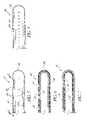
- FIG. 1is a schematic side view of a catheter having features and advantages in accordance with a first embodiment of the present invention
- FIG. 2is a sectional view of the catheter of FIG. 1 , taken along line 2 — 2 of FIG. 1 ;
- FIG. 3is a sectional view of the catheter of FIG. 1 , taken along line 3 — 3 of FIG. 1 ;
- FIG. 4is a perspective view of the end portion and support beam of the catheter of FIG. 1 , illustrating a cross-section taken along line 4 — 4 of FIG. 1 ;
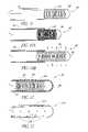
- FIG. 5is a side view of a catheter having features and advantages in accordance with a second embodiment of the present invention.
- FIG. 6is a cross-sectional view of the infusion section of the catheter of FIG. 5 taken along line 6 — 6 of FIG. 5 ;
- FIG. 7is a cross-sectional view of a catheter having features and advantages in accordance with a third embodiment of the present invention.
- FIG. 8is a side view of a catheter having features and advantages in accordance with a fourth embodiment of the present invention.
- FIG. 9is a side view of a catheter having features and advantages in accordance with a fifth embodiment of the present invention.
- FIG. 10Ais a cross-sectional view of the catheter of FIG. 9 , illustrating an unstretched state of the spring;
- FIG. 10Bis a cross-sectional view of the catheter of FIG. 9 , illustrating a stretched state of the spring
- FIG. 11is a cross-sectional view of a catheter having features and advantages in accordance with a sixth embodiment of the present invention.
- FIG. 12is a side view of a catheter having features and advantages in accordance with the sixth embodiment of the present invention.
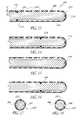
- FIG. 13is a longitudinal cross-sectional view of a catheter having features and advantages in accordance with the seventh embodiment of the present invention.
- FIGS. 14–16are longitudinal cross-sectional views of catheters similar to that of FIG. 13 , illustrating alternative attachments between the internal porous member and the tube;
- FIG. 17is a transverse cross-sectional view of a catheter according to FIGS. 13–16 , wherein the internal porous member is concentric with the outer tube;
- FIG. 18is a transverse cross-sectional view of a catheter according to FIGS. 13–16 , wherein the internal porous member is not concentric with the outer tube;
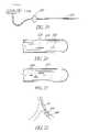
- FIG. 19is a schematic illustration of a catheter of the present invention used in conjunction with an air eliminating filter
- FIG. 20is a side view of a catheter having features and advantages in accordance with the eighth embodiment of the present invention.
- FIG. 21is a side view of a catheter having features and advantages in accordance with the ninth embodiment of the present invention.
- FIG. 22is a schematic illustration of the use of a catheter of the present invention for treating a blood clot.
- FIGS. 1–4illustrate an infusion catheter 20 according to one embodiment of the present invention.
- Catheter 20preferably includes a flexible support 22 ( FIGS. 2–4 ), a non-porous membrane 24 , and a porous membrane 26 .
- the membranes 24 and 26are wrapped around the support 22 to form a plurality of axial lumens between the inner surfaces of the membranes 24 and 26 and the surface of the support 22 , as described in greater detail below.
- the non-porous membrane 24defines a non-infusing section 28 of the catheter 20 , and preferably covers the support 22 from the proximal end thereof to a point 30 , shown in FIG. 1 .
- the porous membrane 26defines an infusion section 32 of catheter 20 , and preferably covers the support 22 from the point 30 to the distal end of support 22 .
- the catheter 20may be configured without a non-porous membrane 24 .
- the porous membrane 26covers the entire length of the support 22 , so that the entire length of the support 22 corresponds to the infusion section of the catheter 20 .
- the infusion sectioncan have any desired length.
- the proximal end of the catheter 20may be connected to a fluid supply 34 containing a fluid 36 such as a liquid medication.
- the distal end of catheter 20may include a cap 48 ( FIG. 4 ) defining the endpoint of the axial lumens within the catheter 20 .
- the catheter 20is inserted into an anatomical system, such as a human body, to deliver fluid medication directly to a wound area within the anatomical system.
- the catheter 20is designed to deliver medication throughout a generally linear segment of the wound area, corresponding to the infusion section 32 of the catheter 20 .
- the catheteris preferably inserted so that the infusion section 32 is positioned within the wound area.
- a physician or nursemay insert the catheter 20 with the aid of an axial guide wire 46 positioned within an axial guide wire lumen 44 of the catheter. Once the catheter is positioned as desired, the guide wire 46 is simply pulled back out through the proximal end of the catheter 20 .
- the catheter 20may be provided without a guide wire or a guide wire lumen.
- FIGS. 2 and 3illustrate a preferred configuration of the support 22 .
- the surface of the support 22includes interruptions such as a plurality of ribs 40 as shown in the figures.
- the interruptionsare configured so that when the membranes 24 and 26 are wrapped around the support 22 , the membranes form a portion of the walls of a plurality of axial lumens 38 within which the fluid 36 may flow.
- a plurality of ribs 40extend radially from a common axial center portion 42 of the support 22 .
- the ribs 40also extend longitudinally along a length of the support 22 , and preferably along the entire length thereof. In the non-infusing section 28 , shown in FIG.
- the non-porous membrane 24is preferably tightly wrapped around the outer edges of the ribs 40 .
- the axial lumens 38are formed between the inner surface of the non-porous membrane 24 and the outer surface of support 22 .
- the porous membrane 26is preferably tightly wrapped around the outer edges of the ribs 40 , so that the axial lumens 38 are formed between the inner surface of porous membrane 26 and the outer surface of support 22 .
- the porous membrane 26may be wrapped around the entire length of the support 20 , thus replacing the non-porous membrane 24 .
- the entire length of the support 22corresponds to the infusion section 32 .
- the support 22may extend only within the infusion section 32 , and a tube may be provided extending from the fluid supply 34 to the proximal end of the support 22 .
- the tubereplaces the non-porous membrane 24 and the portion of the support 22 extending within the non-infusing section 28 of the preferred embodiment. In other words, the tube defines the non-infusing section 28 .
- the number of ribs 40equals the number of axial lumens 38 .
- five ribs 40 and axial lumens 38are shown in FIGS. 2 and 3 , any suitable number of ribs 40 and lumens 38 may be provided, giving due consideration to the goals of providing a plurality of lumens within the catheter 20 , maintaining flexibility, and, if desired, maintaining the fluid independence of the lumens.
- the membranes 24 and 26are preferably glued along the outer edges of the ribs 40 , utilizing any suitable glue, such as a medical grade glue or epoxy. This prevents the membranes 24 and 26 from slipping, which might occur as the catheter is inserted or removed from the anatomy. More preferably, the membranes are glued along the entire length of the outer edges of each of the ribs 40 . Alternatively, the membrane may be wrapped around the support and not secured to the support by a foreign substance. The membrane and support may also be secured to each other by other means known to those of skill in the art. This maintains the fluid independence of the lumens 38 . If desired, an axial guide wire lumen 44 may be provided within the axial central portion 42 of the support 22 . The guide wire lumen 44 is adapted to receive a guide wire 46 which may be used to aid in the insertion of the catheter 20 into the anatomy, as described above and as will be easily understood by those of skill in the art.
- the catheter 20preferably includes an end portion or cap 48 secured to the distal end of support 22 .
- End portion 48may be formed integrally with the support 22 or may be adhesively bonded thereto.
- the proximal end of end portion 48is circular and has a diameter such that the outer surface of the proximal end of end portion 48 is aligned with the outer edges of the ribs 40 of the support 22 , as shown.
- the porous membrane 26is wrapped around the proximal end of the end portion 48 .
- the membrane 26is preferably glued to the end portion 48 so that fluid 36 within the lumens 38 is prevented from exiting the catheter 20 without passing through the walls of the membrane 26 .
- End portion 48blocks axial fluid flow through the distal end of catheter 20 .
- end portion 48may optionally be formed from a porous material to permit some axial dispensation of fluid from the distal end of the catheter 20 , if desired.
- the distal end of end portion 48is preferably dome-shaped, as shown, to permit the catheter 20 to more easily be inserted into an anatomical region.
- the support 22can be formed from a variety of materials, giving due consideration to the goals of flexibility, light-weight, strength, smoothness, and non-reactivity to anatomical systems, i.e., safety. Suitable materials for the support 22 include nylon, polyamide, teflon, and other materials known to those skilled in the art.
- the porous membrane 26is preferably a sponge-like or foam-like material or a hollow fiber. The membrane 26 may be formed from a variety of suitable materials, giving due consideration to the goals of being flexible and non-reactive to anatomical systems.
- the membrane 26preferably has a porosity resulting in substantially uniform dispensation of fluid along the surface area of the infusion section 32 of the catheter 20 , and has an average pore size sufficiently small to limit the flow of bacteria through the membrane walls.
- Some suitable materials for the membrane 26are polyethylene, polysulfone, polyethersulfone, polypropylene, polyvinylidene difluoride, polycarbonate, nylon, or high density polyethylene. These materials are advantageously biocompatible.
- the porous membrane 26may filter out unwanted bacteria from the fluid medication as it passes through the membrane 26 . It is known that the smallest bacteria cannot pass through a pore any smaller than 0.23 microns.
- the average pore size, or pore diameter, of the porous membrane 26may be less than 0.23 microns to prevent bacteria from traversing the membrane 26 .
- the average pore size, or pore diameter, of the membrane 26is preferably within the range of about 0.1 to 1.2 microns, more preferably within the range of about 0.3 to 1 micron, and even more preferably about 0.8 microns.
- the proximal end of catheter 20may be connected to a fluid supply 34 .
- the catheter 20may be configured so that each axial lumen 38 is fluidly independent. In other words, the lumens 38 would not fluidly communicate with one another.
- the catheter 20may be connected to a single fluid supply 34 , so that the fluid 36 flows within each of the lumens 38 .
- the catheter 20may be connected to a plurality of separate fluid supplies so that several different fluids may separately flow within the lumens 38 .
- each lumen 38may be connected to a separate fluid supply so that the total number of different fluids that may be delivered to the anatomy is equal to the number of lumens 38 .
- the fluid lumensneed not be fluidly independent.
- the membrane 26may not be secured to the support 22 along the entire length of the support 22 , thus permitting fluid 36 to migrate between lumens 38 .
- the catheter 20delivers fluid directly to the area of the anatomy that is adjacent to the infusion section 32 .
- the fluid 36 from the fluid source 34is introduced into the axial lumens 38 at the proximal end of the catheter 20 .
- the fluid 36initially flows through the non-infusing section 28 .
- the fluid 36first reaches the infusion section 32 , it soaks into the porous membrane 26 .
- As more fluid 36 enters the infusion section 32it diffuses longitudinally within the walls of the membrane 26 until the entire membrane 26 and infusion section 32 are saturated with fluid. At this point the fluid 36 begins to pass through the membrane 26 , thereby exiting the catheter 20 and entering the anatomy.
- the fluid 36advantageously passes through the entire surface area of the porous membrane 26 at a substantially uniform rate, due to the characteristics of the membrane 26 .
- the fluidis delivered at a substantially equal rate throughout a generally linear segment of the wound area of the anatomy. Furthermore, this advantage is obtained for both low and high pressure fluid delivery.
- FIGS. 5 and 6illustrate a catheter 50 according to an alternative embodiment of the present invention.
- the catheter 50includes an elongated outer tube 52 and an inner elongated tubular porous membrane 54 .
- the tubular membrane 54is preferably concentrically enclosed within the outer tube 52 . More preferably, the tube 52 tightly surrounds and supports the tubular membrane 54 so that a relatively tight fit is achieved between the inner dimensions of tube 52 and the outer dimensions of membrane 54 .
- a plurality of fluid exit holes 56are provided within the tube 52 , preferably throughout the entire circumference thereof. The portion of tube 52 that includes the exit holes 56 defines the infusion section of catheter 50 .
- the tubular membrane 54need only be provided along the length of the infusion section, but could be longer.
- axial exit holesmay be provided within the distal tip 58 of the tube 52 .
- a guide wire and/or guide wire lumenmay be provided to aid in the insertion of the catheter 50 into the anatomy, as will be understood by those skilled in the art.
- the tube 52may be formed from any of a variety of suitable materials, such as nylon, polyimide, teflon and other materials known to those skilled in the art, giving due consideration to the goals of non-reactivity to anatomical systems, flexibility, light-weight, strength, smoothness, and safety.
- the tube 52is preferably a 20 gauge catheter tube, having inside and outside diameters of 0.019 inches and 0.031 inches, respectively.
- the exit holes 56 of tube 52are preferably about 0.015 inches in diameter and provided at equally spaced axial positions along the tube 52 .
- the holes 56are preferably arranged so that every hole is angularly displaced about 120° relative to the longitudinal axis of the tube 52 , from the angular location of the previous hole.
- the axial separation between adjacent exit holes 56is preferably within the range of about 0.125 to 0.25 inches, and more preferably about 3/16 inch.
- the infusion sectioncan have any desirable length. This configuration results in a thorough, uniform delivery of fluid throughout a generally linear segment of the wound area.
- the exit holes 56may be provided in any of a variety of alternative arrangements.
- the tubular porous membrane 54is preferably a sponge-like or foam-like material or a hollow fiber.
- the tubular membrane 54may have an average pore size, or pore diameter, less than 0.23 microns to filter bacteria.
- the pore diameteris preferably within the range of about 0.1 to 1.2 microns, more preferably within the range of about 0.3 to 1 micron, and even more preferably about 0.8 microns.
- the tubular membrane 54may be formed from any of a variety of suitable materials, giving due consideration to the goals of non-reactivity to anatomical systems, maintaining flexibility, fitting within the size constraints of the tube 52 , and having a porosity resulting in the substantially uniform dispensation of fluid through all of the exit holes 56 in tube 52 .
- the membrane 54is polyethylene, polysulfone, polyethersulfone, polypropylene, polyvinylidene difluoride, polycarbonate, nylon, or high density polyethylene. Preferable inside and outside diameters of the tubular membrane 54 are 0.010 inches and 0.018 inches, respectively. In the event that a guide wire 46 is provided, the guide wire may be a stainless steel wire about 0.005 inches in diameter.
- the tube 52may be secured to the membrane 54 by epoxy or other means known to those skilled in the art. Alternatively, the membrane 54 may contact the tube 52 with an interference fit and not use other materials to secure the membrane 54 in the tube 52 .
- the catheter 50delivers fluid to the region of an anatomical system adjacent to the infusion section of catheter 50 .
- the fluidflows into the infusion section, it initially soaks into the tubular porous membrane 54 .
- the fluiddiffuses longitudinally within the walls of the tubular member 54 .
- the membrane 54 and the tubular space thereinare saturated, the fluid passes through the membrane 54 and exits the catheter 50 by flowing through the exit holes 56 of the tube 52 .
- the fluidadvantageously passes through the membrane substantially uniformly throughout the surface area of the membrane 54 , resulting in a substantially uniform flow through substantially all of the exit holes 56 .
- the fluidis delivered at a substantially equal rate throughout the wound area of the anatomy. Furthermore, this advantage is obtained for both low and high pressure fluid delivery.
- FIG. 7illustrates a catheter 70 according to another embodiment of the present invention.
- Catheter 70includes a tube 72 having a plurality of exit holes 76 in side walls of the tube, and a tubular porous membrane 74 concentrically enclosing the tube 72 .
- Catheter 70operates in a similar manner to catheter 50 described above in connection with FIGS. 5 and 6 .
- fluid medicationpasses through the exit holes 76 and then begins to soak into the porous membrane 74 .
- the fluiddiffuses longitudinally within the walls of the membrane until the membrane is saturated. Thereafter, the fluid leaves the membrane walls and enters the anatomy.
- the fluidis dispensed to the anatomy at a substantially uniform rate throughout the surface area of the membrane 74 . As in the previous embodiments, this advantage is obtained for both low and high pressure fluid delivery.
- FIG. 8illustrates a catheter 60 according to another embodiment of the present invention.
- Catheter 60is better suited for relatively high flow rate delivery of fluid to a region within an anatomical system.
- Catheter 60includes a tube 62 having a plurality of exit holes 64 of increasing size. In particular, the more distal exit holes are larger in diameter than the more proximal exit holes.
- the position of the exit holes 64 on the tube 62defines the length of the infusion section of the catheter 60 .
- the infusion sectioncan have any desired length.
- the proximal end of catheter 60is connected to a fluid supply, and a guide wire and/or guide wire lumen may also be provided for aiding in the insertion of catheter 60 into the anatomy.
- exit holes nearer to the distal end of a catheter tubegenerally have increased flow resistance compared to exit holes nearer to the proximal end of the tube.
- the fluid flowing through the more distal holesexperiences a greater pressure drop. Consequently, there is generally a greater flow rate of fluid through the more proximal holes, resulting in non-uniform fluid delivery.
- catheter 60advantageously provides substantially uniform fluid delivery through substantially all of the exit holes 64 , under relatively high flow rate conditions. This is because the larger size of the more distal holes compensates for their increased flow resistance and pressure drop.
- the holes 64are provided in a gradually increasing size which results in substantially uniform fluid delivery.
- the exit holes 64may be sized so that they combine to form a flow-restricting orifice, as described below in connection with the embodiment of FIG. 12 .
- catheter 60is advantageously simple and easy to manufacture. All that is required is to drill a plurality of exit holes 64 in the tube 62 . Furthermore, catheter 60 can sustain greater bending than prior art catheters while maintaining operability. In contrast to prior art catheters, such as the Wang catheter, if the tube 62 is bent somewhat, it will still deliver fluid relatively uniformly. This is because the tube 62 has a single lumen with a relatively large cross-section. When the tube 62 is somewhat bent, fluid flowing within the lumen is less likely to experience blockage and a consequent pressure change which might lead to non-uniform fluid dispensation.
- the tube 62 of catheter 60may be formed from any of a wide variety of materials, giving due consideration to the goals of non-reactivity to anatomical systems, flexibility, light-weight, strength, smoothness, and safety. Suitable materials include nylon, polyimide, teflon, and other materials known to those skilled in the art.
- the infusion sectioncan have any desired length but is preferably about 0.5 to 20 inches long, and more preferably about 10 inches long.
- the diameter of the exit holes 64preferably ranges from about 0.0002 inches at the proximal end of the infusion section to about 0.01 inches at the distal end thereof. The largest, i.e., most distal, exit hole 64 is preferably about 0.25 inches from the distal end of the tube 62 .
- the axial separation between adjacent holes 64is within the range of about 0.125 to 0.25 inches, and more preferably about 3/16 inch.
- the holes 64may be provided so that adjacent holes are angularly displaced by about 120 ⁇ as in the embodiment of FIG. 5 .
- the tube 62may be undesirably weakened.
- FIGS. 9 , 10 A, and 10 Billustrate a catheter 80 according to another embodiment of the present invention.
- the catheter 80comprises a tube 82 , a “weeping” tubular coil spring 84 , and a stop 86 .
- the proximal end of the spring 84is attached to the distal end of the tube 82 so that the tube and spring each define a portion of a central lumen.
- a preferably dome-shaped stop 86is attached to and closes the distal end of the spring 84 .
- the portion of the spring 84 that is distal to the tube 82comprises the infusion section of the catheter 80 . In an unstretched state, shown in FIG.
- the spring 84has adjacent coils in contact with one another so that fluid within the spring and below a threshold dispensation pressure is prevented from exiting the lumen by flowing radially between the coils.
- the spring 84has the property of stretching longitudinally, as shown in FIG. 10B , when the fluid pressure is greater than or equal to the threshold dispensation pressure of the spring, thereby permitting the fluid to be dispensed from the lumen by “weeping,” i.e., leaking radially outward between the coils.
- the springmay stretch radially without elongating to permit fluid to weep through the coils of the spring.
- the springmay stretch both longitudinally and radially to permit weeping, as will be understood by those of skill in the art.
- the fluid between the coils of the springis dispensed substantially uniformly throughout the length and circumference of the portion of the spring that is distal to the tube 82 , i.e., the infusion section.
- the catheter 80can be used for both high or low flow rate fluid delivery.
- the catheter 80is inserted into an anatomical region so that the spring 84 is in a region to which fluid medication is desired to be delivered.
- the springis initially in an unstretched state, as shown in FIG. 10A .
- the fluidis introduced into a proximal end of the tube 82 of the catheter 80 and flows into and through the spring 84 until it reaches the stop 86 .
- the fluidbuilds inside of the spring 84 .
- the spring 84is filled with fluid, the fluid pressure rises more quickly. The fluid imparts a force directed radially outward onto the spring coils. As the pressure builds, the outward force becomes larger.
- the outward forcecauses the spring coils to separate slightly so that the spring stretches longitudinally, as shown in FIG. 10B .
- the coilsmay separate radially, as discussed above.
- the fluidthen flows through the separated coils to be dispensed from the catheter 80 .
- the dispensationis advantageously uniform throughout the infusion section of the catheter 80 .
- the spring 84remains stretched to continually dispense fluid to the desired region within the anatomy. If the fluid introduction temporarily ceases, the fluid pressure within the spring 84 may fall below the threshold dispensation pressure. If so, the spring will compress so that the coils are once again adjacent and the fluid is no longer dispensed.
- Suitable spring typesare 316L or 402L, which can be readily purchased.
- the spring 84has about 200 coils per inch along its length. In this configuration, the spring can advantageously sustain a high degree of bending without leaking fluid from within, and only a severe bend will cause adjacent coils to separate. Thus, the spring 84 may be flexed considerably within an anatomical region without causing fluid to leak and therefore be dispensed to only one region within the anatomy.
- the spring 84can have any desired length to define the length of the infusion section of the catheter 80 .
- the springmay be formed from a variety of materials, giving due consideration to the goals of strength, flexibility, and safety. A preferred material is stainless steel.
- the inside and outside diameters of the springare about 0.02 inches and 0.03 inches, respectively, and the spring wire has a diameter of about 0.005 inches.
- the proximal end of the spring 84is preferably concentrically enclosed within the distal end of the tube 82 .
- the springcan be glued to the inside wall of the tube 82 using, for example, a U.V. adhesive, a potting material, or other bonding materials.
- the springcan be soldered within the tube 82 or be fitted with a proximal plug and tightly plugged into the tube 82 .
- the tube 82 and stop 86can be formed from any of a variety of materials, giving due consideration to the goals of flexibility, light-weight, strength, smoothness, and safety. Suitable materials include nylon, polyimide, teflon, and other materials known to those skilled in the art.
- FIG. 11illustrates a catheter 90 according to another embodiment of the present invention.
- the catheter 90comprises a distally closed tube 92 and a “weeping” tubular coil spring 94 concentrically enclosed within the tube 92 so that a lumen is defined within the tube and spring.
- a plurality of exit holes 96are provided along a length of the tube 92 , in the side wall thereof.
- the length of the tube 92 including such exit holes 96defines an infusion section of the catheter 90 .
- the exit holes 96are preferably provided throughout the walls of the infusion section.
- the infusion sectioncan have any desired length.
- the axial spacing between adjacent holes 96is within the range of about 0.125 to 0.25 inches, and more preferably about 3/16 inch.
- Adjacent holes 96are preferably angularly spaced apart by about 120°.
- the spring 94is preferably enclosed within the infusion section of the catheter and configured similarly to the spring 84 of the embodiment of FIGS. 9 , 10 A and 10 B.
- the spring 94is preferably longer than the infusion portion and positioned so that all of the exit holes 96 are adjacent to the spring 94 . In this configuration, the fluid is prevented from exiting the lumen without flowing between the spring coils.
- a stopis preferably attached to the tube to close the distal end thereof.
- the tube 92may be formed with a closed distal end.
- the catheter 90can be used for high or low flow rate fluid delivery.
- the catheter 90is inserted into an anatomical region so that the infusion section is in a region to which fluid medication is desired to be delivered.
- the fluidis introduced into a proximal end of the tube 92 of the catheter 90 and flows through the spring 94 until it reaches the closed distal end of the tube 92 .
- the fluidbuilds inside of the spring 94 .
- the spring 94becomes filled with fluid, the fluid pressure rises, and the fluid weeps through the spring coils as described above in connection with the embodiment of FIGS. 9 , 10 A, and 10 B.
- the fluidflows through the spring coils substantially uniformly throughout the length and circumference of the spring 94 .
- the fluidthen exits the tube 92 by flowing through the exit holes 96 of the infusion section.
- the exit holesare preferably equal in size so that the fluid flows at a substantially equal rate through the exit holes, advantageously resulting in a generally uniform distribution of fluid throughout a desired region of the anatomy.
- the spring 94As fluid is continually introduced into the catheter 90 , the spring 94 remains stretched to continually dispense fluid from the catheter. If the fluid introduction ceases temporarily, the fluid pressure within the spring 94 may fall below the threshold dispensation pressure. If so, the spring may compress so that the coils are once again adjacent and the fluid is no longer dispensed.
- the spring 94 and tube 92are in contact along the entire length of the spring, so that the fluid weeping through the spring is forced to flow through the holes 96 of the infusion section.
- one end of the spring 94is attached to the inside walls of the tube 92 , permitting the other end of the spring to be displaced as the spring stretches.
- the springcan be glued to the tube 92 with, for example, a U.V. adhesive, potting material, or other bonding materials.
- an end of the springcan be soldered onto the inner walls of the tube 92 .
- the tube 92can be formed from any suitable material.
- the inside walls of the tube 92are preferably smooth so that the spring can more freely stretch and compress.
- FIG. 12illustrates a catheter 100 according to another embodiment of the present invention.
- the catheter 100comprises a distally closed tube 102 having a plurality of exit holes 104 in side walls of the tube 102 .
- the portion of the tube 102 having exit holes 104defines an infusion section of the catheter 100 .
- the exit holes 104are sized to have a combined area of opening that is smaller than the area of any other flow-restricting cross-section or orifice of the catheter.
- the exit holes 104are the flow-restrictor of the catheter 100 .
- the catheteradvantageously dispenses fluid through substantially all of the exit holes 104 .
- a fluid introduced into a proximal end of the tube 102flows through the tube until it reaches the closed distal end thereof.
- the fluidbuilds within the infusion portion of the catheter.
- the fluidis substantially prevented from flowing through the holes 104 , due to their small size.
- the infusion portion of the catheterbecomes filled with fluid.
- the fluid pressurebegins to build. At some point the pressure becomes sufficiently high to force the fluid through the exit holes 104 .
- the fluidflows through substantially all of the exit holes 104 .
- the exit holes 104are all equal in size so that the fluid is dispensed at a substantially equal rate through substantially all of the holes.
- the holes 104are preferably laser drilled to achieve a very small hole diameter.
- a preferred diameter of the exit holes 104is about 0.0002 inches, or about 5 microns.
- Numerous exit holes 104may be provided within the tube 102 .
- the holesare advantageously provided throughout the circumference of the infusion portion of the catheter 100 , to more uniformly deliver the fluid throughout an anatomical region.
- a preferred axial spacing between adjacent holes 104is within the range of about 0.125 to 0.25 inches, and more preferably about 3/16 inch.
- the catheter 100can be used for high or low flow rate fluid delivery.
- the tube 102can be formed from any of a variety of materials known to those skilled in the art and discussed previously.
- FIG. 13illustrates a catheter 200 according to another embodiment of the present invention.
- Catheter 200includes a distally closed tube 202 having a plurality of exit holes 204 therein along an infusion section of the catheter, as in the above-described embodiments.
- the holes 204are desirably provided throughout the circumference of the tube 202 .
- an elongated member 206formed of a porous material.
- the member 206is generally cylindrical in shape, and solid.
- the member 206is positioned within the tube 204 so that an annular space 208 is formed between the outer surface of the member 206 and the inner surface of the tube 202 .
- the member 206extends from the distal end 210 of the tube 202 rearwardly to a point proximal of the infusion section of the catheter. Alternatively, the member 206 may extend along only a portion of the infusion section.
- the member 206is preferably generally concentric with the tube 202 , but non-concentric designs will achieve the advantages of the invention.
- the member 206is manufactured of a flexible material to assist with the placement of the catheter 200 in the body of a patient.
- fluid medication flowing in the tube 202saturates the porous member 206 and flows into the annular region 208 .
- the fluid in the member 206flows into the region 208 and out of the catheter 200 through the exit holes 204 .
- the fluid pressureis uniform throughout the annular region 208 , the fluid flows substantially uniformly through all of the holes 204 .
- the annular region 208may be formed from a porous material that tends to expand when saturated with liquid. If so, the member 206 preferably expands into the annular region 208 without pressing against the tube 202 . This limits the possibility of high pressure regions at the interior surface of the tube 202 , which could cause uneven exit flow of the medication within the wound site. Alternatively, the member 206 may expand and come into contact with the tube 202 , and still accomplish the goals of the present invention.
- the member 206is formed of a porous material having an average pore size preferably within the range of 0.1–50 microns, and more preferably about 0.45 microns.
- the radial width W of the annular region 208is preferably within the range of 0 to about 0.005 microns, and more preferably about 0.003 microns.
- the member 206can be formed of any of a variety of materials, giving due consideration to the goals of porosity, flexibility, strength, and durability. A preferred material is Mentek.
- the member 206can be secured within the tube 202 by the use of an adhesive.
- the adhesiveis applied at the distal end of the member 206 to form a bond with the interior surface of the distal end of the tube 202 .
- adhesiveis applied at or near the proximal end of the infusion section of the catheter 200 .
- the adhesivecan be applied to the circumference of the member 206 at any longitudinal position thereof, forming a ring-shaped bond with the interior surface of the tube 202 .
- a ring-shaped bond 214is provided just proximal of the infusion section of the catheter 200 .
- FIG. 13Other configurations are possible. For example, FIG.
- FIG. 14shows an embodiment in which the adhesive is applied to the distal end of the member 206 to form a bond 216 , and also at generally the center of the infusion section to form a ring-shaped bond 218 .
- FIG. 15shows an embodiment in which the adhesive is applied only to the distal end of the member 206 to form a bond 220 .
- FIG. 16shows an embodiment in which the adhesive is applied only to the center of the infusion section to form a ring-shaped bond 222 .
- the adhesivemay be applied in any of a variety of configurations. Thus, for example, adhesive at the distal end of the catheter (i.e., 212 , 216 , and 220 in FIGS. 13 , 14 , and 15 , respectively) is not required.
- each bondis formed with an adhesive as described below.
- the ring-shaped bond 214can be formed by pouring the adhesive in liquid form through one of the exit holes 204 when the member 206 is in the tube 202 .
- the adhesivehaving a generally high viscosity, tends to flow about the circumference of the member 206 , rather than into the body of the member.
- the adhesivethus forms a ring-shaped bond with the tube 202 , as will be understood by those of skill in the art.
- the adhesiveplugs the exit hole 204 through which it is poured. Any of a variety of different types of adhesives will be acceptable, a preferred adhesive being Loctite.
- the member 206is preferably concentric with the tube 202 .
- FIG. 17shows a cross-section of a catheter 200 in which the member 206 is concentrically enclosed within the tube 202 .
- the member 206may be positioned adjacent to the tube 202 , as shown in FIG. 18 .
- the configuration of FIG. 18may be easier to manufacture than that of FIG. 17 , since the member 206 does not have to be centered within the tube 202 .
- the member 206can be of any desired length and can extend along any desired length of the infusion section of the catheter 200 .
- the member 206does not have to extend to the distal end of the tube 202 .
- the proximal end of the member 206may be either distal or proximal to the proximal end of the infusion section.
- the cathetermay initially have air inside of the catheter tube.
- the catheter 200 shown in FIG. 13may have air inside of the porous material of the member 206 .
- the introduction of liquid medication into the catheterforces the air to flow out of the exit holes. However, this may take several hours.
- the catheteris inserted into a patient while air is inside, and liquid medication is introduced into the catheter, the patient's wound site may receive little or no medication until air is expelled from the catheter tube.
- an air filter 224can be inserted into the catheter tubing proximal the infusion section 226 of the catheter 200 . The filter 224 prevents undesirable air from entering the infusion section 226 of the catheter 200 .
- FIGS. 20 and 21illustrate catheter tubes having elongated exit holes or slots. These catheter tubes may be used in place of the catheter tubes shown and described above.
- FIG. 20shows a tube 230 having exit holes or slots 232 that are elongated in the longitudinal direction of the tube 230 .
- the slots 232are preferably provided throughout the circumference of the tube 230 , along the infusion section of the catheter. Compared to smaller exit holes, the elongated slots 232 tend to increase the flowrate of fluid exiting the catheter, by reducing the flow impedance experienced by the fluid.
- the slots 232may be oriented longitudinally on the catheter body so as not to compromise the structural integrity of the catheter 200 , as will be easily understood by those of skill in the art.
- FIG. 21shows a tube 234 having exit holes or slots 236 whose lengths increase along the length of the tube in the distal direction.
- the slots nearer to the proximal end of the infusion section of the tube 234are shorter in length than the slots nearer to the distal end of the infusion section.
- the catheter tube 234advantageously provides substantially uniform fluid delivery through substantially all of the exit slots 236 , under relatively high flow rate conditions. This is because the larger size of the more distal slots compensates for their increased flow resistance and pressure drop.
- the slots 236are provided in a gradually increasing length, which results in substantially uniform fluid delivery. Further, the elongated slots result in generally higher exit flowrates, as in the embodiment of FIG. 20 .
- an independent guide wire lumenmay be provided within or adjacent to the lumen(s) disclosed, as will be understood by those skilled in the art.
- a catheter 20(reference numeral 20 is used to identify the catheter, but any of the above-described catheters can be used) is inserted into a blood clot 240 inside of a vein or artery 242 .
- the infusion section of the catheteris within the blood clot 240 .
- Liquid medicationis preferably introduced into the proximal end of the catheter tube.
- the medicationexits the catheter 20 at a uniform rate throughout the infusion section to dissolve the clot 240 .
- any of the catheter embodiments described hereinmay be used in a variety of applications including, but not limited to, peripheral nerve blocks, intrathecal infusions, epideral infusions, intravascular infusions, intraarterial infusions and intraarticular infusions, as well as in wound site pain management.
- any of the catheters disclosed hereinmay be integral with a fluid line eminating from an infusion pump as opposed to being an independent catheter designed to be connected or secured to an infusion pump.
Landscapes
- Health & Medical Sciences (AREA)
- Life Sciences & Earth Sciences (AREA)
- Animal Behavior & Ethology (AREA)
- Engineering & Computer Science (AREA)
- Anesthesiology (AREA)
- Biomedical Technology (AREA)
- Heart & Thoracic Surgery (AREA)
- Hematology (AREA)
- General Health & Medical Sciences (AREA)
- Public Health (AREA)
- Veterinary Medicine (AREA)
- Pulmonology (AREA)
- Biophysics (AREA)
- Media Introduction/Drainage Providing Device (AREA)
- Infusion, Injection, And Reservoir Apparatuses (AREA)
Abstract
Description
Claims (30)
Priority Applications (2)
| Application Number | Priority Date | Filing Date | Title |
|---|---|---|---|
| US10/104,171US7004923B2 (en) | 1999-07-19 | 2002-03-21 | Catheter for uniform delivery of medication |
| US11/364,767US7438711B2 (en) | 1999-07-19 | 2006-02-28 | Catheter for uniform delivery of medication |
Applications Claiming Priority (4)
| Application Number | Priority Date | Filing Date | Title |
|---|---|---|---|
| US09/363,228US6350253B1 (en) | 1999-07-19 | 1999-07-19 | Catheter for uniform delivery of medication |
| PCT/US2000/019746WO2001005210A2 (en) | 1999-07-19 | 2000-07-19 | Catheter for uniform delivery of medication |
| US10/104,171US7004923B2 (en) | 1999-07-19 | 2002-03-21 | Catheter for uniform delivery of medication |
| US3191302A | 2002-05-21 | 2002-05-21 |
Related Parent Applications (2)
| Application Number | Title | Priority Date | Filing Date |
|---|---|---|---|
| US10/031,913ContinuationUS7780638B1 (en) | 1999-07-19 | 2000-07-19 | Catheter for uniform delivery of medication |
| PCT/US2000/019746ContinuationWO2001005210A2 (en) | 1999-07-19 | 2000-07-19 | Catheter for uniform delivery of medication |
Related Child Applications (1)
| Application Number | Title | Priority Date | Filing Date |
|---|---|---|---|
| US11/364,767ContinuationUS7438711B2 (en) | 1999-07-19 | 2006-02-28 | Catheter for uniform delivery of medication |
Publications (2)
| Publication Number | Publication Date |
|---|---|
| US20030181887A1 US20030181887A1 (en) | 2003-09-25 |
| US7004923B2true US7004923B2 (en) | 2006-02-28 |
Family
ID=31996418
Family Applications (3)
| Application Number | Title | Priority Date | Filing Date |
|---|---|---|---|
| US10/104,171Expired - LifetimeUS7004923B2 (en) | 1999-07-19 | 2002-03-21 | Catheter for uniform delivery of medication |
| US10/828,923Expired - Fee RelatedUS7569045B2 (en) | 1999-07-19 | 2004-04-21 | Catheter for uniform delivery of medication |
| US12/534,764Expired - LifetimeUS8628633B2 (en) | 1999-07-19 | 2009-08-03 | Catheter for uniform delivery of medication |
Family Applications After (2)
| Application Number | Title | Priority Date | Filing Date |
|---|---|---|---|
| US10/828,923Expired - Fee RelatedUS7569045B2 (en) | 1999-07-19 | 2004-04-21 | Catheter for uniform delivery of medication |
| US12/534,764Expired - LifetimeUS8628633B2 (en) | 1999-07-19 | 2009-08-03 | Catheter for uniform delivery of medication |
Country Status (1)
| Country | Link |
|---|---|
| US (3) | US7004923B2 (en) |
Cited By (52)
| Publication number | Priority date | Publication date | Assignee | Title |
|---|---|---|---|---|
| US20030158538A1 (en)* | 1999-07-19 | 2003-08-21 | Deniega Jose Castillo | Catheter for uniform delivery of medication |
| US20030216710A1 (en)* | 2002-03-26 | 2003-11-20 | Hurt Robert F. | Catheter |
| US20040073194A1 (en)* | 2002-10-14 | 2004-04-15 | Medicinelodge, Inc. | Catheter assemblies for controlled movement of fluid |
| US20040199144A1 (en)* | 1999-07-19 | 2004-10-07 | Deniega Jose Castillo | Catheter for uniform delivery of medication |
| US20050106225A1 (en)* | 2003-09-16 | 2005-05-19 | Roger Massengale | Fluid medication delivery device |
| US20060135941A1 (en)* | 1999-07-19 | 2006-06-22 | Porto James D | Anti-microbial catheter |
| US20070213688A1 (en)* | 2003-05-21 | 2007-09-13 | Klein Jeffrey A | Infiltration cannula |
| US20070255230A1 (en)* | 2006-04-27 | 2007-11-01 | Sdgi Holdings, Inc. | Vented directional delivery cannula with openings of different size for use with flowable materials and method for use thereof |
| US20070255231A1 (en)* | 2006-04-27 | 2007-11-01 | Sdgi Holdings, Inc. | Vented directional delivery cannula with openings of different shape for use with flowable materials and method for use thereof |
| US20080300530A1 (en)* | 2007-06-04 | 2008-12-04 | I-Flow Corporation | Stimulating catheter |
| US20090155770A1 (en)* | 2007-12-12 | 2009-06-18 | Kimberly-Clark Worldwide, Inc. | Implantable devices for fiber optic based detection of nosocomial infection |
| US20090254062A1 (en)* | 2008-04-03 | 2009-10-08 | Mcglothlin Mark W | Infusion catheters with slit valves and of simplified construction |
| US20100249747A1 (en)* | 2009-03-26 | 2010-09-30 | Organic Medical Ventures, L.L.C. | Transdermal venous access locking solution |
| US20110071483A1 (en)* | 2007-08-06 | 2011-03-24 | Benjamin Gordon | Apparatus |
| US20110257622A1 (en)* | 2010-03-24 | 2011-10-20 | Amr Salahieh | Intravascular Tissue Disruption |
| US20120095404A1 (en)* | 2010-10-18 | 2012-04-19 | Roger Dillard Massengale | Echogenic Nerve Block Apparatus and System |
| US8177772B2 (en) | 2005-09-26 | 2012-05-15 | C. R. Bard, Inc. | Catheter connection systems |
| US8337475B2 (en) | 2004-10-12 | 2012-12-25 | C. R. Bard, Inc. | Corporeal drainage system |
| WO2013032464A1 (en) | 2011-08-31 | 2013-03-07 | Organic Medical Ventures, L.L.C. | Transdermal venous access locking solutions |
| USD679804S1 (en) | 2011-09-22 | 2013-04-09 | Vital 5, Llc | Catheter |
| US8568369B2 (en) | 2010-08-05 | 2013-10-29 | Cook Medical Technologies Llc | Infusion catheter and method |
| US8636721B2 (en) | 2003-11-20 | 2014-01-28 | Henry M. Jackson Foundation For The Advancement Of Military Medicine, Inc. | Portable hand pump for evacuation of fluids |
| WO2014074237A1 (en) | 2012-11-09 | 2014-05-15 | Solodex Llc | Continuous anesthesia nerve conduction apparatus, system and method thereof |
| US8805466B2 (en) | 2008-11-11 | 2014-08-12 | Shifamed Holdings, Llc | Low profile electrode assembly |
| US20140316327A1 (en)* | 2011-05-18 | 2014-10-23 | Solodex Llc | Continuous anesthesia nerve conduction apparatus, system and method thereof |
| US8957060B2 (en) | 2009-11-30 | 2015-02-17 | Jeffrey Alan KLEIN | Tumescent antibiotic solution |
| WO2015044808A1 (en) | 2013-09-26 | 2015-04-02 | Avent, Inc. | Catheter-positioning slide cover clamp assembly |
| US9072296B2 (en) | 2009-03-26 | 2015-07-07 | Organic Medical Ventures, L.L.C. | Transdermal venous access locking solutions |
| WO2015102934A1 (en) | 2013-12-30 | 2015-07-09 | Avent, Inc. | Catheter site insertion plug |
| US9179968B2 (en) | 2010-05-10 | 2015-11-10 | St. Jude Medical Luxembourg Holding S.À.R.L. | Irrigated finned ablation head |
| US9265913B2 (en) | 2010-09-22 | 2016-02-23 | Vital 5, Llc | Catheter assembly |
| US9333031B2 (en) | 2013-04-08 | 2016-05-10 | Apama Medical, Inc. | Visualization inside an expandable medical device |
| US9402973B2 (en) | 2007-07-06 | 2016-08-02 | Vital 5, Llc | Constrained fluid delivery device |
| US9427498B2 (en) | 2009-03-26 | 2016-08-30 | Organic Medical Ventures, L.L.C. | Syringe treated with transdermal venous access locking solutions and method of treating the syringe |
| US9433209B2 (en) | 2009-03-26 | 2016-09-06 | Organic Medical Ventures, L.L.C. | Transdermal venous access locking solutions |
| US9446224B2 (en) | 2010-09-22 | 2016-09-20 | Vital 5, L.L.C. | Barrier catheter |
| US9636440B2 (en) | 2006-10-13 | 2017-05-02 | Bluesky Medical Group Inc. | Control circuit and method for negative pressure wound treatment apparatus |
| US9655677B2 (en) | 2010-05-12 | 2017-05-23 | Shifamed Holdings, Llc | Ablation catheters including a balloon and electrodes |
| US9668654B2 (en) | 2011-05-18 | 2017-06-06 | Sundar Rajendran | Ultrasound monitored continuous anesthesia nerve conduction apparatus and method by bolus injection |
| US9694166B2 (en) | 2002-03-26 | 2017-07-04 | Medtronics Ps Medical, Inc. | Method of draining cerebrospinal fluid |
| US9795442B2 (en) | 2008-11-11 | 2017-10-24 | Shifamed Holdings, Llc | Ablation catheters |
| US9821141B2 (en) | 2012-07-26 | 2017-11-21 | Twin Star Medical, Inc. | Macroporous catheter |
| US10098694B2 (en) | 2013-04-08 | 2018-10-16 | Apama Medical, Inc. | Tissue ablation and monitoring thereof |
| US10328187B2 (en) | 2007-07-02 | 2019-06-25 | Smith & Nephew Plc | Systems and methods for controlling operation of negative pressure wound therapy apparatus |
| US10349824B2 (en) | 2013-04-08 | 2019-07-16 | Apama Medical, Inc. | Tissue mapping and visualization systems |
| US10617801B2 (en) | 2007-08-06 | 2020-04-14 | Smith & Nephew Plc | Canister status determination |
| US10736693B2 (en) | 2015-11-16 | 2020-08-11 | Apama Medical, Inc. | Energy delivery devices |
| US11213481B2 (en) | 2004-06-25 | 2022-01-04 | Hk Pharma | Tumescent drug delivery |
| US11344318B2 (en) | 2016-07-18 | 2022-05-31 | Merit Medical Systems, Inc. | Inflatable radial artery compression device |
| US12121648B2 (en) | 2007-08-06 | 2024-10-22 | Smith & Nephew Plc | Canister status determination |
| US12290302B2 (en) | 2011-09-30 | 2025-05-06 | Covidien Lp | Energy delivery device and methods of use |
| US12426864B2 (en) | 2021-06-18 | 2025-09-30 | Merit Medical Systems, Inc. | Hemostasis devices and methods of use |
Families Citing this family (31)
| Publication number | Priority date | Publication date | Assignee | Title |
|---|---|---|---|---|
| US20070161949A1 (en)* | 2006-01-06 | 2007-07-12 | Knox Susan J | Catheter system for minimizing retrograde bacterial transmission from a catheter tubing |
| US20080287982A1 (en)* | 2007-05-16 | 2008-11-20 | Boston Scientific Scimed, Inc. | Catheters for electrolytically detachable embolic devices |
| US20100228178A1 (en)* | 2009-03-06 | 2010-09-09 | Mcgraw J Kevin | Hemodialysis catheter apparatus |
| EP2414028A4 (en)* | 2009-03-30 | 2012-09-19 | Medingo Ltd | DEVICES AND METHOD FOR INCREASING THE ACTIVE ABSORPTION RATE |
| US20130345665A1 (en)* | 2012-06-26 | 2013-12-26 | Gary Swaddle | Catheter system |
| EP2679268A1 (en)* | 2012-06-27 | 2014-01-01 | Peak Medical Ltd. | Infusion catheter system |
| AU2015209240B2 (en) | 2014-01-24 | 2019-06-13 | Avent, Inc. | Traumatic wound dressing system with wrap |
| WO2015112810A1 (en) | 2014-01-24 | 2015-07-30 | Avent, Inc. | Traumatic wound dressing system with conformal cover |
| JP6655102B2 (en) | 2015-06-18 | 2020-02-26 | アヴェント インコーポレイテッド | Echogenic catheter member |
| CA2989771C (en) | 2015-06-18 | 2021-03-02 | Avent, Inc. | Echogenic coil member for a catheter assembly |
| US10765834B2 (en) | 2015-07-20 | 2020-09-08 | Strataca Systems Limited | Ureteral and bladder catheters and methods of inducing negative pressure to increase renal perfusion |
| US12064567B2 (en) | 2015-07-20 | 2024-08-20 | Roivios Limited | Percutaneous urinary catheter |
| HUE049050T2 (en) | 2015-07-20 | 2020-08-28 | Strataca Systems Ltd | Ureteral and bladder catheters |
| US11040180B2 (en) | 2015-07-20 | 2021-06-22 | Strataca Systems Limited | Systems, kits and methods for inducing negative pressure to increase renal function |
| US11040172B2 (en) | 2015-07-20 | 2021-06-22 | Strataca Systems Limited | Ureteral and bladder catheters and methods of inducing negative pressure to increase renal perfusion |
| US10918827B2 (en) | 2015-07-20 | 2021-02-16 | Strataca Systems Limited | Catheter device and method for inducing negative pressure in a patient's bladder |
| US10926062B2 (en) | 2015-07-20 | 2021-02-23 | Strataca Systems Limited | Ureteral and bladder catheters and methods of inducing negative pressure to increase renal perfusion |
| US11229771B2 (en) | 2015-07-20 | 2022-01-25 | Roivios Limited | Percutaneous ureteral catheter |
| US10512713B2 (en) | 2015-07-20 | 2019-12-24 | Strataca Systems Limited | Method of removing excess fluid from a patient with hemodilution |
| US11541205B2 (en) | 2015-07-20 | 2023-01-03 | Roivios Limited | Coated urinary catheter or ureteral stent and method |
| US10493232B2 (en) | 2015-07-20 | 2019-12-03 | Strataca Systems Limited | Ureteral catheters, bladder catheters, systems, kits and methods for inducing negative pressure to increase renal function |
| MX387162B (en) | 2015-07-21 | 2025-03-18 | Avent Inc | ULTRASOUND CATHETER ASSEMBLY. |
| CA3014643A1 (en)* | 2016-02-26 | 2017-08-31 | Neuronano Ab | Method of providing an implantation site in soft tissue |
| EP3535013A4 (en) | 2016-11-02 | 2021-01-20 | The Cooper Health System | Method and apparatus for delivery of cell therapies |
| CN107281619B (en)* | 2017-08-03 | 2022-12-06 | 南华大学附属第二医院 | Thrombolytic catheter |
| JP2020531159A (en) | 2017-08-25 | 2020-11-05 | ストラタカ システムズ リミテッド | Indwelling pump to facilitate removal of urine from the urinary tract |
| CN111568601B (en)* | 2019-02-15 | 2023-03-31 | 金诺机械医疗有限公司 | Filler-injected orthopedic implant |
| US11638805B2 (en) | 2019-02-27 | 2023-05-02 | Avent, Inc. | Multi-headed catheter for fluid delivery |
| KR20220124144A (en)* | 2019-09-02 | 2022-09-13 | 스템플랜트 엘엘씨 | Methods and Devices for Delivery of Cell Therapy |
| US20230173223A1 (en)* | 2021-12-02 | 2023-06-08 | Saint Louis University | Urinary catheter for endoscope |
| WO2024047081A1 (en) | 2022-09-02 | 2024-03-07 | Universiteit Gent | Catheter for delivery of therapeutic liquid formulation |
Citations (27)
| Publication number | Priority date | Publication date | Assignee | Title |
|---|---|---|---|---|
| US3595241A (en) | 1969-02-19 | 1971-07-27 | David S Sheridan | Insured internal flow medicosurgical tubes |
| US3821956A (en) | 1973-08-14 | 1974-07-02 | D Gordhamer | Bovine teat dilator and medicament dispenser |
| US3841308A (en) | 1973-10-15 | 1974-10-15 | Medical Evaluation Devices & I | Distally valved catheter device |
| US3938529A (en)* | 1974-07-22 | 1976-02-17 | Gibbons Robert P | Indwelling ureteral catheter |
| US4976689A (en)* | 1984-09-18 | 1990-12-11 | Medtronic Versaflex, Inc. | Outer exchange catheter system |
| US5066278A (en) | 1989-08-09 | 1991-11-19 | Siemens Aktiengesellschaft | Implantable injection body |
| US5184627A (en) | 1991-01-18 | 1993-02-09 | Boston Scientific Corporation | Infusion guidewire including proximal stiffening sheath |
| US5201723A (en)* | 1991-08-27 | 1993-04-13 | Cordis Corporation | Inclined side holes in the distal end of a catheter |
| US5267979A (en) | 1990-09-17 | 1993-12-07 | E-Z-Em, Inc. | Pressure responsive valve catheter |
| US5269755A (en) | 1992-09-11 | 1993-12-14 | Sherwood Medical Company | Catheter with outer membrane medicament delivery system |
| US5356388A (en) | 1992-09-22 | 1994-10-18 | Target Therapeutics, Inc. | Perfusion catheter system |
| US5376083A (en) | 1990-10-31 | 1994-12-27 | Lake Region Manufacturing Company, Inc. | Steerable infusion guide wire |
| US5405316A (en)* | 1993-11-17 | 1995-04-11 | Magram; Gary | Cerebrospinal fluid shunt |
| US5425723A (en) | 1993-12-30 | 1995-06-20 | Boston Scientific Corporation | Infusion catheter with uniform distribution of fluids |
| US5569219A (en)* | 1994-09-13 | 1996-10-29 | Hakki; A-Hamid | Collapsible catheter |
| US5643228A (en) | 1995-11-13 | 1997-07-01 | Uresil Corporation | Catheter |
| US5702372A (en) | 1995-02-08 | 1997-12-30 | Medtronic, Inc. | Lined infusion catheter |
| US5709874A (en) | 1993-04-14 | 1998-01-20 | Emory University | Device for local drug delivery and methods for using the same |
| US5776111A (en) | 1996-11-07 | 1998-07-07 | Medical Components, Inc. | Multiple catheter assembly |
| US5800407A (en) | 1995-12-21 | 1998-09-01 | Eldor; Joseph | Multiple hole epidural catheter |
| US5833652A (en) | 1995-09-18 | 1998-11-10 | Y. Pierre Gobin | Component mixing catheter |
| US5846216A (en) | 1995-04-06 | 1998-12-08 | G & P Technologies, Inc. | Mucous membrane infusor and method of use for dispensing medications |
| US6123688A (en)* | 1995-08-22 | 2000-09-26 | Mdc Investment Holdings, Inc. | Pre-filled retractable needle injection devices |
| US6350253B1 (en)* | 1999-07-19 | 2002-02-26 | I-Flow Corporation | Catheter for uniform delivery of medication |
| US6623449B2 (en)* | 1991-07-15 | 2003-09-23 | Larry D. Paskar | Catheter with up-going and down-going configurations |
| US6676643B2 (en)* | 2000-03-24 | 2004-01-13 | Nicor, Inc. | Anesthesia conduction catheter |
| US20040064129A1 (en)* | 1999-07-19 | 2004-04-01 | Deniega Jose Castillo | Catheter for uniform delivery of medication |
Family Cites Families (55)
| Publication number | Priority date | Publication date | Assignee | Title |
|---|---|---|---|---|
| US3601320A (en)* | 1968-06-26 | 1971-08-24 | Neil M Du Plessis | Apparatus for breaking up a directional fluid stream |
| US4054139A (en) | 1975-11-20 | 1977-10-18 | Crossley Kent B | Oligodynamic catheter |
| US4186745A (en)* | 1976-07-30 | 1980-02-05 | Kauzlarich James J | Porous catheters |
| US4180068A (en)* | 1978-04-13 | 1979-12-25 | Motion Control, Incorporated | Bi-directional flow catheter with retractable trocar/valve structure |
| US4402684A (en)* | 1981-09-16 | 1983-09-06 | The Kendall Company | Cannula with soft tip |
| FR2539298A1 (en) | 1983-01-14 | 1984-07-20 | Descartes Paris V Universite R | Device for the treatment of hydrocephalus with an improved catheter |
| DE3400874C1 (en) | 1984-01-12 | 1985-02-07 | Karl Dr. 6301 Pohlheim Aigner | Double-lumen catheter for a device for in-vivo blood purification |
| SE442377B (en)* | 1984-06-29 | 1985-12-23 | Mediplast Ab | CATS, HEALTH OR SIMILAR DEVICE |
| US5069874A (en)* | 1986-09-08 | 1991-12-03 | Oiles Corporation | Method for reducing high-load, low-speed wear resistance in sliding members |
| US6210395B1 (en)* | 1987-09-30 | 2001-04-03 | Lake Region Mfg., Inc. | Hollow lumen cable apparatus |
| FR2622805A1 (en) | 1987-11-09 | 1989-05-12 | Cleef Jean Francois Van | Catheter for angiectomy by suction |
| US5201724A (en) | 1987-12-23 | 1993-04-13 | The Victoria University Of Manchester | Catheter |
| US4994047A (en)* | 1988-05-06 | 1991-02-19 | Menlo Care, Inc. | Multi-layer cannula structure |
| US4846791A (en)* | 1988-09-02 | 1989-07-11 | Advanced Medical Technology & Development Corp. | Multi-lumen catheter |
| US4985022A (en) | 1988-11-23 | 1991-01-15 | Med Institute, Inc. | Catheter having durable and flexible segments |
| JPH02142576A (en)* | 1988-11-25 | 1990-05-31 | Japan Gore Tex Inc | catheter |
| US5032113A (en)* | 1989-04-13 | 1991-07-16 | Scimed Life Systems, Inc. | Innerless catheter |
| US5021044A (en)* | 1989-01-30 | 1991-06-04 | Advanced Cardiovascular Systems, Inc. | Catheter for even distribution of therapeutic fluids |
| WO1991007203A1 (en)* | 1989-11-22 | 1991-05-30 | W.L. Gore & Associates, Inc. | A catheter device |
| US5971954A (en)* | 1990-01-10 | 1999-10-26 | Rochester Medical Corporation | Method of making catheter |
| JPH06503972A (en) | 1990-06-26 | 1994-05-12 | アドヴァンスド カーディオヴァスキュラーシステムズ インコーポレイテッド | Intravascular drug delivery method and catheter therefor |
| WO1992011895A1 (en) | 1990-12-28 | 1992-07-23 | Boston Scientific Corporation | Balloon drug delivery system |
| JP3131948B2 (en) | 1991-04-26 | 2001-02-05 | 株式会社ニッショー | Peritoneal dialysis machine |
| US5213576A (en)* | 1991-06-11 | 1993-05-25 | Cordis Corporation | Therapeutic porous balloon catheter |
| CA2071353C (en)* | 1991-12-10 | 1998-10-06 | Amy M. Wendell | Microbore catheter with side port(s) |
| WO1994001160A1 (en) | 1992-07-14 | 1994-01-20 | Arrow International Investment Corporation | Unibody construction dual durometer epidural catheter |
| US5370610A (en)* | 1993-02-09 | 1994-12-06 | Reynolds; James R. | Surgical drainage tube system |
| GB9307312D0 (en) | 1993-04-07 | 1993-06-02 | United Surgical Services Ltd | Surgical wound dressings |
| US5348536A (en)* | 1993-08-02 | 1994-09-20 | Quinton Instrument Company | Coextruded catheter and method of forming |
| AU680265B2 (en)* | 1993-08-18 | 1997-07-24 | Ramasoft3 Pty Limited | Optical fibre flat screen |
| US5735892A (en)* | 1993-08-18 | 1998-04-07 | W. L. Gore & Associates, Inc. | Intraluminal stent graft |
| US5462521A (en)* | 1993-12-21 | 1995-10-31 | Angeion Corporation | Fluid cooled and perfused tip for a catheter |
| DE4402475C2 (en) | 1994-01-28 | 1999-03-25 | Vygon Gmbh & Co Kg | Catheter that can be placed using a Tuohy needle |
| CA2199418A1 (en) | 1994-09-09 | 1996-03-14 | Applied Medical Resources Corporation | Embolectomy catheter and method for making same |
| US5790874A (en)* | 1994-09-30 | 1998-08-04 | Kabushiki Kaisha Toshiba | Information processing apparatus for reducing power consumption by minimizing hamming distance between consecutive instruction |
| WO1996016690A1 (en) | 1994-11-29 | 1996-06-06 | Becton, Dickinson And Company | A catheter having wall support to prevent collapse thereof |
| US5891084A (en)* | 1994-12-27 | 1999-04-06 | Lee; Vincent W. | Multiple chamber catheter delivery system |
| WO1996033761A1 (en)* | 1995-04-28 | 1996-10-31 | Medtronic, Inc. | Intraparenchymal infusion catheter system |
| US5843050A (en)* | 1995-11-13 | 1998-12-01 | Micro Therapeutics, Inc. | Microcatheter |
| WO1997018936A1 (en) | 1995-11-22 | 1997-05-29 | Rijksuniversiteit Te Groningen | A method and a system for manufacturing a catheter and a catheter manufactured by that method |
| US6235007B1 (en)* | 1995-11-27 | 2001-05-22 | Therox, Inc. | Atraumatic fluid delivery devices |
| US5957899A (en) | 1995-11-27 | 1999-09-28 | Therox, Inc. | High pressure transluminal fluid delivery device |
| US6102903A (en)* | 1995-12-14 | 2000-08-15 | Medtronics, Inc. | Device and method for selectively delivering fluid into an anatomical lumen |
| US6117125A (en) | 1996-05-02 | 2000-09-12 | Cook Incorporated | Method for predetermining uniform flow rate of a fluid from a tubular body and device therefrom |
| US5814064A (en)* | 1997-03-06 | 1998-09-29 | Scimed Life Systems, Inc. | Distal protection device |
| US5947940A (en)* | 1997-06-23 | 1999-09-07 | Beisel; Robert F. | Catheter reinforced to prevent luminal collapse and tensile failure thereof |
| US5957901A (en)* | 1997-10-14 | 1999-09-28 | Merit Medical Systems, Inc. | Catheter with improved spray pattern for pharmaco-mechanical thrombolysis therapy |
| GB9726820D0 (en) | 1997-12-20 | 1998-02-18 | Smiths Industries Plc | Tubes |
| US6183461B1 (en)* | 1998-03-11 | 2001-02-06 | Situs Corporation | Method for delivering a medication |
| US6280786B1 (en)* | 1998-06-22 | 2001-08-28 | Sara Lee Corporation | Production of corn dogs |
| US7004923B2 (en)* | 1999-07-19 | 2006-02-28 | I-Flow Corporation | Catheter for uniform delivery of medication |
| US6716895B1 (en) | 1999-12-15 | 2004-04-06 | C.R. Bard, Inc. | Polymer compositions containing colloids of silver salts |
| US6629969B2 (en) | 2001-07-26 | 2003-10-07 | Durect Corporation | Catheter for modification of agent formulation |
| BRPI0410351A (en) | 2003-05-12 | 2006-07-04 | I Flow Corp | catheter for uniform distribution of medication |
| FR2863189B1 (en) | 2003-12-03 | 2006-03-10 | Jean-Louis Negroni | METHOD FOR DRILLING OPTICAL LENSES USING A DIGITAL CONTROL DRILL, AND DEVICE FOR CARRYING OUT SAID METHOD |
- 2002
- 2002-03-21USUS10/104,171patent/US7004923B2/ennot_activeExpired - Lifetime
- 2004
- 2004-04-21USUS10/828,923patent/US7569045B2/ennot_activeExpired - Fee Related
- 2009
- 2009-08-03USUS12/534,764patent/US8628633B2/ennot_activeExpired - Lifetime
Patent Citations (30)
| Publication number | Priority date | Publication date | Assignee | Title |
|---|---|---|---|---|
| US3595241A (en) | 1969-02-19 | 1971-07-27 | David S Sheridan | Insured internal flow medicosurgical tubes |
| US3821956A (en) | 1973-08-14 | 1974-07-02 | D Gordhamer | Bovine teat dilator and medicament dispenser |
| US3841308A (en) | 1973-10-15 | 1974-10-15 | Medical Evaluation Devices & I | Distally valved catheter device |
| US3938529A (en)* | 1974-07-22 | 1976-02-17 | Gibbons Robert P | Indwelling ureteral catheter |
| US4976689A (en)* | 1984-09-18 | 1990-12-11 | Medtronic Versaflex, Inc. | Outer exchange catheter system |
| US5066278A (en) | 1989-08-09 | 1991-11-19 | Siemens Aktiengesellschaft | Implantable injection body |
| US5267979A (en) | 1990-09-17 | 1993-12-07 | E-Z-Em, Inc. | Pressure responsive valve catheter |
| US5376083A (en) | 1990-10-31 | 1994-12-27 | Lake Region Manufacturing Company, Inc. | Steerable infusion guide wire |
| US5184627A (en) | 1991-01-18 | 1993-02-09 | Boston Scientific Corporation | Infusion guidewire including proximal stiffening sheath |
| US6623449B2 (en)* | 1991-07-15 | 2003-09-23 | Larry D. Paskar | Catheter with up-going and down-going configurations |
| US5201723A (en)* | 1991-08-27 | 1993-04-13 | Cordis Corporation | Inclined side holes in the distal end of a catheter |
| US5269755A (en) | 1992-09-11 | 1993-12-14 | Sherwood Medical Company | Catheter with outer membrane medicament delivery system |
| US5356388A (en) | 1992-09-22 | 1994-10-18 | Target Therapeutics, Inc. | Perfusion catheter system |
| US5709874A (en) | 1993-04-14 | 1998-01-20 | Emory University | Device for local drug delivery and methods for using the same |
| US5405316A (en)* | 1993-11-17 | 1995-04-11 | Magram; Gary | Cerebrospinal fluid shunt |
| US5425723A (en) | 1993-12-30 | 1995-06-20 | Boston Scientific Corporation | Infusion catheter with uniform distribution of fluids |
| US5569219A (en)* | 1994-09-13 | 1996-10-29 | Hakki; A-Hamid | Collapsible catheter |
| US5702372A (en) | 1995-02-08 | 1997-12-30 | Medtronic, Inc. | Lined infusion catheter |
| US5846216A (en) | 1995-04-06 | 1998-12-08 | G & P Technologies, Inc. | Mucous membrane infusor and method of use for dispensing medications |
| US6123688A (en)* | 1995-08-22 | 2000-09-26 | Mdc Investment Holdings, Inc. | Pre-filled retractable needle injection devices |
| US5833652A (en) | 1995-09-18 | 1998-11-10 | Y. Pierre Gobin | Component mixing catheter |
| US5643228A (en) | 1995-11-13 | 1997-07-01 | Uresil Corporation | Catheter |
| US5800407A (en) | 1995-12-21 | 1998-09-01 | Eldor; Joseph | Multiple hole epidural catheter |
| US5776111A (en) | 1996-11-07 | 1998-07-07 | Medical Components, Inc. | Multiple catheter assembly |
| US6350253B1 (en)* | 1999-07-19 | 2002-02-26 | I-Flow Corporation | Catheter for uniform delivery of medication |
| US20020133142A1 (en)* | 1999-07-19 | 2002-09-19 | Deniega Jose Castillo | Catheter for uniform delivery of medication |
| US20030158538A1 (en)* | 1999-07-19 | 2003-08-21 | Deniega Jose Castillo | Catheter for uniform delivery of medication |
| US20020082547A1 (en)* | 1999-07-19 | 2002-06-27 | Deniega Jose Castillo | Catheter for uniform delivery of medication |
| US20040064129A1 (en)* | 1999-07-19 | 2004-04-01 | Deniega Jose Castillo | Catheter for uniform delivery of medication |
| US6676643B2 (en)* | 2000-03-24 | 2004-01-13 | Nicor, Inc. | Anesthesia conduction catheter |
Cited By (109)
| Publication number | Priority date | Publication date | Assignee | Title |
|---|---|---|---|---|
| US8343135B2 (en) | 1999-07-19 | 2013-01-01 | Kimberly-Clark Worldwide, Inc. | Anti-microbial catheter |
| US7547302B2 (en) | 1999-07-19 | 2009-06-16 | I-Flow Corporation | Anti-microbial catheter |
| US20110190731A1 (en)* | 1999-07-19 | 2011-08-04 | I-Flow | Method for Fluid Delivery and Catheters for Use with Same |
| US20040199144A1 (en)* | 1999-07-19 | 2004-10-07 | Deniega Jose Castillo | Catheter for uniform delivery of medication |
| US8628633B2 (en) | 1999-07-19 | 2014-01-14 | Kimberly-Clark Worldwide, Inc. | Catheter for uniform delivery of medication |
| US20060135941A1 (en)* | 1999-07-19 | 2006-06-22 | Porto James D | Anti-microbial catheter |
| US20060149192A1 (en)* | 1999-07-19 | 2006-07-06 | Deniega Jose C | Catheter for uniform delivery of medication |
| US7438711B2 (en) | 1999-07-19 | 2008-10-21 | I-Flow Corporation | Catheter for uniform delivery of medication |
| US20100000666A1 (en)* | 1999-07-19 | 2010-01-07 | I-Flow Corporation | Catheter for uniform delivery of medication |
| US20030158538A1 (en)* | 1999-07-19 | 2003-08-21 | Deniega Jose Castillo | Catheter for uniform delivery of medication |
| US7569045B2 (en) | 1999-07-19 | 2009-08-04 | I-Flow Corporation | Catheter for uniform delivery of medication |
| US20090187152A1 (en)* | 1999-07-19 | 2009-07-23 | L-Flow Corporation | Anti-microbial catheter |
| US8043465B2 (en) | 1999-07-19 | 2011-10-25 | I-Flow Corporation | Catheter for uniform delivery of medication |
| US8328771B2 (en)* | 1999-07-19 | 2012-12-11 | Roger Dillard Massengale | Method for fluid delivery and catheters for use with same |
| US9084870B2 (en) | 1999-07-19 | 2015-07-21 | Avent, Inc. | Catheter for uniform delivery of medication |
| US7780638B1 (en) | 1999-07-19 | 2010-08-24 | I-Flow Corporation | Catheter for uniform delivery of medication |
| US20070142817A1 (en)* | 2002-03-26 | 2007-06-21 | Medtronic Ps Medical, Inc. | Catheter |
| US20030216710A1 (en)* | 2002-03-26 | 2003-11-20 | Hurt Robert F. | Catheter |
| US9694166B2 (en) | 2002-03-26 | 2017-07-04 | Medtronics Ps Medical, Inc. | Method of draining cerebrospinal fluid |
| US7326196B2 (en)* | 2002-10-14 | 2008-02-05 | Breg, Inc. | Catheter assemblies for controlled movement of fluid |
| US20040073194A1 (en)* | 2002-10-14 | 2004-04-15 | Medicinelodge, Inc. | Catheter assemblies for controlled movement of fluid |
| US8105310B2 (en) | 2003-05-21 | 2012-01-31 | Klein Jeffrey A | Infiltration cannula |
| US20070213688A1 (en)* | 2003-05-21 | 2007-09-13 | Klein Jeffrey A | Infiltration cannula |
| US8323266B2 (en) | 2003-09-16 | 2012-12-04 | Kimberly-Clark Worldwide, Inc. | Fluid medication delivery device |
| US8241269B2 (en) | 2003-09-16 | 2012-08-14 | Kimberly-Clark Worldwide, Inc. | Fluid medication delivery device |
| US7854732B2 (en) | 2003-09-16 | 2010-12-21 | I-Flow Corporation | Fluid medication delivery device |
| US7771413B2 (en)* | 2003-09-16 | 2010-08-10 | I-Flow Corporation | Fluid medication delivery device |
| US20050106225A1 (en)* | 2003-09-16 | 2005-05-19 | Roger Massengale | Fluid medication delivery device |
| US20090105667A1 (en)* | 2003-09-16 | 2009-04-23 | I-Flow Corporation | Fluid medication delivery device |
| US7470266B2 (en) | 2003-09-16 | 2008-12-30 | I-Flow Corporation | Fluid medication delivery device |
| US9393353B2 (en) | 2003-11-20 | 2016-07-19 | The Henry M. Jackson Foundation For The Advancement Of Military Medicine, Inc. | Portable hand pump for evacuation of fluids |
| US8636721B2 (en) | 2003-11-20 | 2014-01-28 | Henry M. Jackson Foundation For The Advancement Of Military Medicine, Inc. | Portable hand pump for evacuation of fluids |
| US10213532B2 (en) | 2003-11-20 | 2019-02-26 | The Henry M. Jackson Foundation For The Advancement Of Military Medicine, Inc. | Portable hand pump for evacuation of fluids |
| US9907887B2 (en) | 2003-11-20 | 2018-03-06 | The Henry M. Jackson Foundation For The Advancement Of Military Medicine, Inc. | Portable hand pump for evacuation of fluids |
| US11213481B2 (en) | 2004-06-25 | 2022-01-04 | Hk Pharma | Tumescent drug delivery |
| US9623030B2 (en) | 2004-06-25 | 2017-04-18 | Jeffrey Alan KLEIN | Tumescent antibiotic solution |
| US10322083B2 (en) | 2004-06-25 | 2019-06-18 | Hk Pharma | Tumescent drug delivery |
| US10946123B2 (en) | 2004-10-12 | 2021-03-16 | Merit Medical Systems, Inc. | Corporeal drainage system |
| US8337475B2 (en) | 2004-10-12 | 2012-12-25 | C. R. Bard, Inc. | Corporeal drainage system |
| US9913935B2 (en) | 2004-10-12 | 2018-03-13 | C. R. Bard, Inc. | Corporeal drainage system |
| US8814839B2 (en) | 2004-10-12 | 2014-08-26 | C. R. Bard, Inc. | Corporeal drainage system |
| US9295764B2 (en) | 2004-10-12 | 2016-03-29 | C. R. Bard, Inc. | Corporeal drainage system |
| US8235971B2 (en) | 2005-09-26 | 2012-08-07 | C. R. Bard, Inc. | Catheter connection systems |
| US8177772B2 (en) | 2005-09-26 | 2012-05-15 | C. R. Bard, Inc. | Catheter connection systems |
| US20070255231A1 (en)* | 2006-04-27 | 2007-11-01 | Sdgi Holdings, Inc. | Vented directional delivery cannula with openings of different shape for use with flowable materials and method for use thereof |
| US20070255230A1 (en)* | 2006-04-27 | 2007-11-01 | Sdgi Holdings, Inc. | Vented directional delivery cannula with openings of different size for use with flowable materials and method for use thereof |
| US9636440B2 (en) | 2006-10-13 | 2017-05-02 | Bluesky Medical Group Inc. | Control circuit and method for negative pressure wound treatment apparatus |
| US10709826B2 (en) | 2006-10-13 | 2020-07-14 | Smith & Nephew, Inc. | Control circuit and method for negative pressure wound treatment apparatus |
| US11850348B2 (en) | 2006-10-13 | 2023-12-26 | Smith & Nephew, Inc. | Control circuit and method for negative pressure wound treatment apparatus |
| US8005538B2 (en) | 2007-06-04 | 2011-08-23 | I-Flow Corporation | Stimulating catheter |
| US20080300530A1 (en)* | 2007-06-04 | 2008-12-04 | I-Flow Corporation | Stimulating catheter |
| US11969541B2 (en) | 2007-07-02 | 2024-04-30 | Smith & Nephew Plc | Systems and methods for controlling operation of negative pressure wound therapy apparatus |
| US10328187B2 (en) | 2007-07-02 | 2019-06-25 | Smith & Nephew Plc | Systems and methods for controlling operation of negative pressure wound therapy apparatus |
| US9402973B2 (en) | 2007-07-06 | 2016-08-02 | Vital 5, Llc | Constrained fluid delivery device |
| US20110071483A1 (en)* | 2007-08-06 | 2011-03-24 | Benjamin Gordon | Apparatus |
| US8974429B2 (en) | 2007-08-06 | 2015-03-10 | Smith & Nephew Plc | Apparatus and method for applying topical negative pressure |
| US12121648B2 (en) | 2007-08-06 | 2024-10-22 | Smith & Nephew Plc | Canister status determination |
| US10617801B2 (en) | 2007-08-06 | 2020-04-14 | Smith & Nephew Plc | Canister status determination |
| US11559620B2 (en) | 2007-08-06 | 2023-01-24 | Smith & Nephew Plc | Canister status determination |
| US10994060B2 (en) | 2007-08-06 | 2021-05-04 | Smith & Nephew Plc | Canister status determination |
| US20090155770A1 (en)* | 2007-12-12 | 2009-06-18 | Kimberly-Clark Worldwide, Inc. | Implantable devices for fiber optic based detection of nosocomial infection |
| US20090254062A1 (en)* | 2008-04-03 | 2009-10-08 | Mcglothlin Mark W | Infusion catheters with slit valves and of simplified construction |
| US9795442B2 (en) | 2008-11-11 | 2017-10-24 | Shifamed Holdings, Llc | Ablation catheters |
| US9717557B2 (en) | 2008-11-11 | 2017-08-01 | Apama Medical, Inc. | Cardiac ablation catheters and methods of use thereof |
| US8805466B2 (en) | 2008-11-11 | 2014-08-12 | Shifamed Holdings, Llc | Low profile electrode assembly |
| US10251700B2 (en) | 2008-11-11 | 2019-04-09 | Shifamed Holdings, Llc | Ablation catheters |
| US11744639B2 (en) | 2008-11-11 | 2023-09-05 | Shifamed Holdings Llc | Ablation catheters |
| US9610006B2 (en) | 2008-11-11 | 2017-04-04 | Shifamed Holdings, Llc | Minimally invasive visualization systems |
| US20100249747A1 (en)* | 2009-03-26 | 2010-09-30 | Organic Medical Ventures, L.L.C. | Transdermal venous access locking solution |
| US9433209B2 (en) | 2009-03-26 | 2016-09-06 | Organic Medical Ventures, L.L.C. | Transdermal venous access locking solutions |
| US9427498B2 (en) | 2009-03-26 | 2016-08-30 | Organic Medical Ventures, L.L.C. | Syringe treated with transdermal venous access locking solutions and method of treating the syringe |
| US9380780B2 (en) | 2009-03-26 | 2016-07-05 | Organic Medical Ventures, L.L.C. | Transdermal venous access locking solutions |
| US9072296B2 (en) | 2009-03-26 | 2015-07-07 | Organic Medical Ventures, L.L.C. | Transdermal venous access locking solutions |
| US8957060B2 (en) | 2009-11-30 | 2015-02-17 | Jeffrey Alan KLEIN | Tumescent antibiotic solution |
| US8840601B2 (en)* | 2010-03-24 | 2014-09-23 | Shifamed Holdings, Llc | Intravascular tissue disruption |
| US20110257622A1 (en)* | 2010-03-24 | 2011-10-20 | Amr Salahieh | Intravascular Tissue Disruption |
| US10631926B2 (en) | 2010-05-10 | 2020-04-28 | St. Jude Medical International Holding S.À R.L. | Irrigated finned ablation head |
| US9179968B2 (en) | 2010-05-10 | 2015-11-10 | St. Jude Medical Luxembourg Holding S.À.R.L. | Irrigated finned ablation head |
| US10149963B2 (en) | 2010-05-11 | 2018-12-11 | Vital 5, Llc | Catheter assembly |
| US9655677B2 (en) | 2010-05-12 | 2017-05-23 | Shifamed Holdings, Llc | Ablation catheters including a balloon and electrodes |
| US8568369B2 (en) | 2010-08-05 | 2013-10-29 | Cook Medical Technologies Llc | Infusion catheter and method |
| US9446224B2 (en) | 2010-09-22 | 2016-09-20 | Vital 5, L.L.C. | Barrier catheter |
| US9265913B2 (en) | 2010-09-22 | 2016-02-23 | Vital 5, Llc | Catheter assembly |
| AU2016202667B2 (en)* | 2010-10-18 | 2017-02-16 | Avent, Inc. | Echogenic nerve block apparatus and system |
| US9254146B2 (en)* | 2010-10-18 | 2016-02-09 | Avent, Inc. | Echogenic nerve block apparatus and system |
| US20120095404A1 (en)* | 2010-10-18 | 2012-04-19 | Roger Dillard Massengale | Echogenic Nerve Block Apparatus and System |
| AU2011319493B2 (en)* | 2010-10-18 | 2016-03-03 | Avent, Inc. | Echogenic nerve block apparatus and system |
| US10080549B2 (en) | 2010-10-18 | 2018-09-25 | Avent, Inc. | Echogenic nerve block apparatus and system |
| US10238830B2 (en)* | 2011-05-18 | 2019-03-26 | Solodex Llc | Continuous anesthesia nerve conduction apparatus, system and method thereof |
| EP3263038A1 (en) | 2011-05-18 | 2018-01-03 | Solodex LLC | Continuous anesthesia nerve conduction apparatus, system and method |
| US8986283B2 (en) | 2011-05-18 | 2015-03-24 | Solo-Dex, Llc | Continuous anesthesia nerve conduction apparatus, system and method thereof |
| US10315003B2 (en) | 2011-05-18 | 2019-06-11 | Solodex Llc | Continuous anesthesia nerve conduction apparatus, system and method thereof |
| US20140316327A1 (en)* | 2011-05-18 | 2014-10-23 | Solodex Llc | Continuous anesthesia nerve conduction apparatus, system and method thereof |
| US9668654B2 (en) | 2011-05-18 | 2017-06-06 | Sundar Rajendran | Ultrasound monitored continuous anesthesia nerve conduction apparatus and method by bolus injection |
| WO2013032464A1 (en) | 2011-08-31 | 2013-03-07 | Organic Medical Ventures, L.L.C. | Transdermal venous access locking solutions |
| USD679804S1 (en) | 2011-09-22 | 2013-04-09 | Vital 5, Llc | Catheter |
| US12290302B2 (en) | 2011-09-30 | 2025-05-06 | Covidien Lp | Energy delivery device and methods of use |
| US9821141B2 (en) | 2012-07-26 | 2017-11-21 | Twin Star Medical, Inc. | Macroporous catheter |
| WO2014074237A1 (en) | 2012-11-09 | 2014-05-15 | Solodex Llc | Continuous anesthesia nerve conduction apparatus, system and method thereof |
| US9333031B2 (en) | 2013-04-08 | 2016-05-10 | Apama Medical, Inc. | Visualization inside an expandable medical device |
| US11439298B2 (en) | 2013-04-08 | 2022-09-13 | Boston Scientific Scimed, Inc. | Surface mapping and visualizing ablation system |
| US11684415B2 (en) | 2013-04-08 | 2023-06-27 | Boston Scientific Scimed, Inc. | Tissue ablation and monitoring thereof |
| US10349824B2 (en) | 2013-04-08 | 2019-07-16 | Apama Medical, Inc. | Tissue mapping and visualization systems |
| US10098694B2 (en) | 2013-04-08 | 2018-10-16 | Apama Medical, Inc. | Tissue ablation and monitoring thereof |
| WO2015044808A1 (en) | 2013-09-26 | 2015-04-02 | Avent, Inc. | Catheter-positioning slide cover clamp assembly |
| WO2015102934A1 (en) | 2013-12-30 | 2015-07-09 | Avent, Inc. | Catheter site insertion plug |
| US10736693B2 (en) | 2015-11-16 | 2020-08-11 | Apama Medical, Inc. | Energy delivery devices |
| US11344318B2 (en) | 2016-07-18 | 2022-05-31 | Merit Medical Systems, Inc. | Inflatable radial artery compression device |
| US12426864B2 (en) | 2021-06-18 | 2025-09-30 | Merit Medical Systems, Inc. | Hemostasis devices and methods of use |
Also Published As
| Publication number | Publication date |
|---|---|
| US20030181887A1 (en) | 2003-09-25 |
| US7569045B2 (en) | 2009-08-04 |
| US20040199144A1 (en) | 2004-10-07 |
| US8628633B2 (en) | 2014-01-14 |
| US20100000666A1 (en) | 2010-01-07 |
Similar Documents
| Publication | Publication Date | Title |
|---|---|---|
| US7004923B2 (en) | Catheter for uniform delivery of medication | |
| US7438711B2 (en) | Catheter for uniform delivery of medication | |
| US7510550B2 (en) | Catheter for uniform delivery of medication | |
| US7854730B2 (en) | Catheter for uniform delivery of medication | |
| CA2525649C (en) | Catheter for uniform delivery of medication | |
| US20030181864A1 (en) | Catheter for uniform delivery of medication | |
| HK1122515A (en) | Catheter for uniform delivery of medication |
Legal Events
| Date | Code | Title | Description |
|---|---|---|---|
| STCF | Information on status: patent grant | Free format text:PATENTED CASE | |
| FPAY | Fee payment | Year of fee payment:4 | |
| AS | Assignment | Owner name:KIMBERLY-CLARK WORLDWIDE, INC., WISCONSIN Free format text:ASSIGNMENT OF ASSIGNORS INTEREST;ASSIGNOR:I-FLOW CORPORATION;REEL/FRAME:026577/0329 Effective date:20110124 | |
| FPAY | Fee payment | Year of fee payment:8 | |
| AS | Assignment | Owner name:AVENT, INC., GEORGIA Free format text:ASSIGNMENT OF ASSIGNORS INTEREST;ASSIGNOR:KIMBERLY-CLARK WORLDWIDE, INC.;REEL/FRAME:034754/0001 Effective date:20141030 | |
| AS | Assignment | Owner name:MORGAN STANLEY SENIOR FUNDING, INC., NEW YORK Free format text:SECURITY INTEREST;ASSIGNOR:AVENT, INC.;REEL/FRAME:035375/0867 Effective date:20150227 | |
| FPAY | Fee payment | Year of fee payment:12 | |
| AS | Assignment | Owner name:CITIBANK, N.A., NEW YORK Free format text:INTELLECTUAL PROPERTY SECURITY INTEREST ASSIGNMENT AGREEMENT;ASSIGNOR:MORGAN STANLEY SENIOR FUNDING, INC.;REEL/FRAME:048173/0137 Effective date:20181029 | |
| AS | Assignment | Owner name:AVANOS MEDICAL SALES, LLC, GEORGIA Free format text:RELEASE BY SECURED PARTY;ASSIGNOR:CITIBANK, N.A.;REEL/FRAME:060557/0062 Effective date:20220624 Owner name:AVENT, INC., GEORGIA Free format text:RELEASE BY SECURED PARTY;ASSIGNOR:CITIBANK, N.A.;REEL/FRAME:060557/0062 Effective date:20220624 |