US7003433B2 - Apparatus and method for event correlation and problem reporting - Google Patents
Apparatus and method for event correlation and problem reportingDownload PDFInfo
- Publication number
- US7003433B2 US7003433B2US11/034,192US3419205AUS7003433B2US 7003433 B2US7003433 B2US 7003433B2US 3419205 AUS3419205 AUS 3419205AUS 7003433 B2US7003433 B2US 7003433B2
- Authority
- US
- United States
- Prior art keywords
- event
- events
- symptoms
- readable media
- computer readable
- Prior art date
- Legal status (The legal status is an assumption and is not a legal conclusion. Google has not performed a legal analysis and makes no representation as to the accuracy of the status listed.)
- Expired - Lifetime
Links
Images


Classifications
- G—PHYSICS
- G06—COMPUTING OR CALCULATING; COUNTING
- G06F—ELECTRIC DIGITAL DATA PROCESSING
- G06F11/00—Error detection; Error correction; Monitoring
- G06F11/22—Detection or location of defective computer hardware by testing during standby operation or during idle time, e.g. start-up testing
- G06F11/2257—Detection or location of defective computer hardware by testing during standby operation or during idle time, e.g. start-up testing using expert systems
- G—PHYSICS
- G06—COMPUTING OR CALCULATING; COUNTING
- G06F—ELECTRIC DIGITAL DATA PROCESSING
- G06F11/00—Error detection; Error correction; Monitoring
- G06F11/22—Detection or location of defective computer hardware by testing during standby operation or during idle time, e.g. start-up testing
- G06F11/2273—Test methods
- G—PHYSICS
- G06—COMPUTING OR CALCULATING; COUNTING
- G06F—ELECTRIC DIGITAL DATA PROCESSING
- G06F11/00—Error detection; Error correction; Monitoring
- G06F11/30—Monitoring
- G06F11/34—Recording or statistical evaluation of computer activity, e.g. of down time, of input/output operation ; Recording or statistical evaluation of user activity, e.g. usability assessment
- G06F11/3466—Performance evaluation by tracing or monitoring
- G—PHYSICS
- G06—COMPUTING OR CALCULATING; COUNTING
- G06F—ELECTRIC DIGITAL DATA PROCESSING
- G06F2201/00—Indexing scheme relating to error detection, to error correction, and to monitoring
- G06F2201/86—Event-based monitoring
Definitions
- This inventionrelates to the field of event correlation and, more particularly, to a method and apparatus for efficiently determining the occurrence of and the source of problems in a complex system based on observable events.
- the inventionhas broad application to any type of complex system including computer networks, satellites, communication systems, weapons systems, complex vehicles such as spacecraft, medical diagnosis, and financial market analysis.
- Problemscan include faults, performance degradation, intrusion attempts and other exceptional operational conditions requiring handling. Problems generate observable events, and these events can be monitored, detected, reported, analyzed and acted upon by humans or by programs. However, as systems have become more complex, the rate at which observable events occur has increased super-linearly, making problem management more difficult.
- Automated management systemscan help to cope with this increase in the number and complexity of events by (1) automating the collection and reporting of events, thereby reducing the load on human operators or programs; (2) using event correlation techniques to group distinct events, thereby compressing the event stream into a form more easily managed by human operators; (3) mapping groups of events to their underlying causes, thus reducing the time between faults and repairs; and (4) automatically correcting diagnosed problems, thereby minimizing operator intervention.
- Event correlation and management techniquesare a particularly important method of reducing the number of symptoms in a system which need to be analyzed and accurately determining the number and identity of discrete problems which need to be rectified. Unless events are correlated, a single problem in a single subsystem could result in multiple, uncoordinated corrective actions. This can lead to wasteful resources spent on duplicate efforts and inconsistent corrective actions which result in an escalation of problems.
- Event correlation and management approachescan be generally grouped into five categories: (1) rule-based reasoning; (2) case-based reasoning; (3) reasoning with generic models; (4) probability networks; and (5) model-based reasoning.
- rule-based reasoning(2) case-based reasoning
- reasoning with generic models(3) reasoning with generic models
- probability networks(4) probability networks
- model-based reasoninga number of different architectures have been considered to carry out event correlation and management.
- the following terminologyis defined:
- KNOWLEDGE REPRESENTATIONThe format and means for representing knowledge about the system being monitored, such as the types of network components and the network topology. Such knowledge maybe stored in a hierarchical relational or object-oriented database.
- KNOWLEDGE ACOUISITIONThe methods and means for acquiring the knowledge about the system to be monitored. Ideally, knowledge is automatically obtained during system operation to minimize human resource requirements. However, in actuality much knowledge acquisition involves humans familiar with the operation and idiosyncrasies of a system.
- EVENT CORRELATIONThe methods and means for detecting the occurrence of exceptional events in a complex system and identifying which particular event occurred and where it occurred.
- the set of events which occur and can be detected in the system over a period of timewill be referred to as an “event stream.” It will be noted that the location of the event is not necessarily the location where it is observed, because events can propagate across related entities in a system. Although every possible reportable measurement (such as voltage level, disk error, or temperature level) could be considered to be an “event”, many of these measurements do not contribute to identifying exceptional events in the system.
- Event correlationtakes as input an event stream, detects occurrence of exceptional events, identifies the particular events that have occurred, and reports them as an output.
- Event correlationcan take place in both the space and time dimensions. For example, two events whose sources are determined to be in the same protocol layer in the same network element may be related spatially. However, they may not be correlated if they occur on different days, because they would not be related temporally.
- Rule-based expert systemsgenerally contain two components:
- Rule-based reasoningcan proceed in one of two possible modes of operation.
- FORWARD CHAINING modethe working memory is constantly scanned for facts which can be used to satisfy the condition part of each rule. When a condition is found, the rule is executed. Executing a rule means that the working memory is updated based on the conclusion contained in the rule. These newly updated data can be used to satisfy the conditions of other rules, resulting in a “chain reaction” of rule executions.
- BACKWARD CHAINING modethe system is presented with a “goal” working memory datum, which it is asked to either confirm or deny.
- the systemsearches for rules whose action part could assert the goal; for each such rule, the condition corresponding to the action is checked against the working memory to see if it is satisfied.
- the conditionscan be satisfied by either finding the appropriate working memory data or by finding other rules whose conditions are satisfied which could assert the desired working memory data.
- Rule-based expert systemsbenefit from straightforward knowledge acquisition because the “if-then” format of the rules often mimics the format of expert knowledge.
- the knowledge basecan be incrementally modified because rules can be added or modified easily.
- attempts to automate knowledge acquisition for such systemshave produced limited results.
- Rule-based expert systemscan be used to perform event detection and event correlation by providing a link between the working memory and the event stream.
- the search associated with rule-based systemscan be of exponential complexity in the number of rules (size of knowledge base). It is difficult to ensure that firing sequences of a complex rule-based system actually terminate.
- the complexity of the searchis also exponential in the size of the working memory.
- the working memoryincludes the events to be correlated. If the system involves a large number of events, the working memory (and therefore the search) may be unbounded.
- a rule based systemcan be very sensitive to lost or spurious event data.
- a rule-based systemcan be sensitive even to the order in which input patterns are provided. Different orders may lead to different results and time to converge. There are no techniques to ensure that a rule based system contains sufficient rules to resolve correlations.
- an arbitrary set of rulesmay execute an indefinite or even infinite number of rules before completion; a rule-based algorithm can involve an arbitrarily long or even infinite cycle of rule firings.
- a minor defect in the knowledge basecould render the system useless.
- the knowledge baseis “brittle” in that if the problem domain changes in any way, the system will no longer perform.
- Case-based reasoning methods and systemsinvolve storing knowledge as a repository of successful cases of solved problems called a case base.
- a case baseWhen the system is presented with a problem, it searches the case base for similar cases. Once the similar cases are retrieved, various problem-solving strategies must be adapted to the case at hand. If the adapted strategy successfully solves the problem, then the newly solved problem can be added to the case base with the adapted solution.
- Determinatorsare a way of narrowing the similarity criteria to attributes of a problem which are relevant to solving the problem. For example, the solution to the problem “file transfer throughput is slow” could be determined by looking at bandwidth, network load, packet collision rate and packet deferment rate; these would constitute determinators. Parameterized adaptation such as interpolating among solutions to similar problems located in the case base can be used to provide solutions to new problems.
- case-based approacheshave inherent disadvantages.
- the case basegrows as problems are solved over a long period of time, and there may be more cases in the case base than is strictly necessary to solve the range of problems encountered.
- Effortmust be expended not only on acquiring knowledge for storage in the case base, but also on identifying and creating appropriate determinators to operate the system effectively. It may be necessary for experts to directly enter cases into the system to fully capture their value, and it may be difficult to determine when the case base is sufficiently large to solve a prescribed range of problems. In some cases, the experts may even need to participate directly in knowledge acquisition while the system is operating. The system may not be usable until a large number of problems have been encountered and solved.
- case-based systemscan involve significant and slow search, can be difficult to validate and may be sensitive to loss or spurious generation of symptoms (these may be seen as different cases).
- Generic modelsrely on generic algorithms, rather than expert knowledge, to correlate events based on an abstraction of the system architecture and its components.
- each eventcan be normalized to include a list of all possible faults which could have been responsible for the event. (This is an abstraction of a real event which could carry much more varied information). Then all the various events are collected and the intersection of their sources is determined and output as the diagnosis.
- a rule of the form “if A then B”can be augmented with a certainty factor: “if A then B with certainty 90%.”
- the element of a probability networkis a proposition, which is a hypothesis about the state of the system being monitored. For example, the hypothesis “node A is faulty” is a proposition. A probability is associated with each proposition, which is its a priori probability of truth. Additionally, probabilities can be assigned to the relationships between propositions. For example, “the truth of proposition A causes the truth of proposition B with probability 90%.” When an event occurs, the probability of the proposition representing the occurrence of that event is updated to 100%, and this change is propagated to other propositions in the network based on the relationships. A diagnosis can be generated by simply listing those propositions having the highest probabilities.
- Probability networksmay be advantageous in that they can produce hypotheses with a precise confidence level. However, in the worst case, every proposition has a causal relationship with every other proposition, in which case the number of connections in the probability network would be approximately equal to the square of the number of propositions in the network. Moreover, the complexity of an event correlation algorithm using probability networks is typically high.
- Fuzzy logicdescribes uncertain knowledge in terms of subintervals of [0, 1]. For example, the likelihood of a problem can be represented as an interval [0, 0.4]. The certainty (fuzziness) of the problem is given by 0.4. Fuzzy logic, in a manner similar to Boolean logic, defines operations in terms of intervals. The product of two intervals is their intersection, while the sum is their union.
- FBRcan be used to model causality among problems and symptoms using a matrix R of fuzziness indicators.
- this approachhas severe disadvantages. For example, there may be no solutions to the equation, or there may be many solutions to the equation.
- a small error in the modele.g., in the fuzziness indicators of R
- a small errorcan also transform an equation with multiple solutions into one with no solutions and vice versa, or yield completely different solutions. Lost or spurious symptoms may result in no solution to the equation rather than detecting the possible loss.
- the FBR approachdoes not permit simple reduction of symptoms to be observed (e.g., reducing a fuzziness matrix R to a much smaller matrix R′).
- the complexity of FBRcan be exponential in the number of problems, because it seeks to compute all possible combinations of problems that could yield a particular observation. In short, the FBR approach does not solve the problems outlined above with respect to complexity and performance.
- Model-based reasoninginvolves creating a model which represents the underlying system being monitored.
- a modelis a finite state machine (FSM) for modelling possible states of the system. As messages are observed at any location in the system, the model is used to update the estimate of the current state of the system.
- FSMfinite state machine
- an FSM representationcan quickly grow to unmanageable size because of the simplicity of the model.
- the time complexity of an event correlation algorithm using an FSMis typically linear in the number of events at each machine.
- a number of different architectureshave been proposed for carrying out event correlation and management along the principles discussed above. These can be generally grouped into: (A) blackboard architectures; (B) event detection architectures; (C) network modelling architectures; and (D) simulation architectures.
- a blackboard architecturegenerally comprises one or more knowledge sources (KS's), a blackboard, and a control shell.
- Each KSis a knowledge base which has a specific domain of expertise.
- the blackboardis a data structure which acts as a shared memory for the KS's; each KS can read from and write to the blackboard.
- the control shellcoordinates the activities of the various KS's based on “triggering” blackboard events. Once a KS is scheduled by the control shell, it scans the blackboard for knowledge that it needs to perform its inference. The output of a scheduled KS may be further blackboard events (i.e., changes to the data on the blackboard).
- a basic systemcould have two knowledge sources: a protocol diagnoser and a hardware diagnoser.
- the protocol diagnoser KScould be implemented with model-based reasoning using an FSM model of the protocol, while the hardware diagnoser could use a rule-based system as outlined above.
- the protocol diagnoser KScould write a diagnosis to the blackboard indicating that a given router is not obeying the protocol specifications.
- the hardware diagnoser KScould then read this diagnosis from the blackboard and initiate a hardware diagnosis for the given router. To achieve this sequence, the control shell would be instructed to activate the hardware diagnoser KS whenever the protocol diagnoser indicates a hardware fault.
- blackboard architecturesare modular (i.e., they allow the integration of many types of reasoning methods for a single system) and allow various KS's to be developed independently (i.e., knowledge can be acquired independently from experts of each domain and then assembled into a complete system), they also have disadvantages. For example, because the blackboard must act as a global memory for all KS's, all communication must be converted into a common format understandable by all other KS's. Thus, the integration task can be enormous. Furthermore, it may be impossible to decide which KS should be scheduled without special knowledge about what is contained in the KS's themselves.
- a rule-based systemcan be implemented for event detection whereby generated events are converted into working memory elements and inserted into the working memory of the rule-based system.
- the rule basewould contain rules matching these memory elements, and would report a subset or summary of the events to an event correlator by inserting other working memory elements into the correlator's working memory.
- OVERLOAD eventFor example, suppose it is desired that an OVERLOAD event be generated when a delay on 20% of the communications links in a network exceeds 5 seconds.
- One approachwould be to continuously insert all current delays on all communications links into the working memory of the event detector, and the event detector could define the OVERLOAD event. However, this would cause a large load on the system whether or not the OVERLOAD event was of interest.
- OVERLOAD eventcan be defined as a data pattern event which is generated whenever one of the event retrieval queries returns a value.
- One advantage of this approachis that new events can be defined in a declarative manner using a database query language. However, it may be difficult to implement because there must be a mapping from the query language to actual queries to the objects in the network. Moreover, when a new query is produced, it may be difficult to determine the cost of producing the event to which the query maps; not all queries which can be generated are capable of an efficient implementation. Therefore, the complexity of this approach could be difficult to predict.
- the system under observationcan be modelled as an object-oriented hierarchy, where network elements are modelled as object having associated functions for querying the values of the object's attributes. Calls to these functions would invoke a query to the database or return a value which was stored from a previous query. For example, GET_CPU_UTILZATION would return the current CPU utilization rate for a particular CPU.
- Logical objects representing abstractions of other objectscan be defined to further expand the model. Diagnostic knowledge may be derived and represented in an object-oriented fashion, thus providing a manageable database. However, as with other object-oriented approaches, the performance of the system can be poor. Moreover, this model only provides one component of an event correlation system (i.e., the knowledge base); it does not address how to correlate events and provide a problem diagnosis.
- Simulationcan be used to help predict underlying problems in a system. If the simulator can be made to operate in real-time, then the performance of the system can be tested under realistic conditions. The simulation can be monitored more easily than a real system, so that hidden trends may be uncovered and added to an event correlation system. Simulation techniques, however, do not generally address the problem of correlating events and producing a diagnosis of underlying problems.
- the present inventionovercomes the aforementioned problems by providing a method and apparatus for efficiently determining problem events from observable symptoms.
- the inventors of the present inventionhave discovered that by treating the detection and identification of exceptional events in a system as a coding problem, it can be performed extremely efficiently. More specifically, event correlation (correlating observed events to specific problems) can be split into two separate activities: (1) generating efficient codes (sets of symptom events) for problem identification, and (2) decoding the event stream. Detection and identification of problems in the system can be done efficiently because (1) redundant and inefficient data is eliminated during code generation, leaving a greatly reduced amount of data to be analyzed during the decoding phase, and (2) comparing codes against observed symptoms is of minimal computational complexity.
- An exceptional eventmay be an event that requires some handling action (e.g., a problem such as a defective disk drive, or adding a workstation to a LAN) while a symptom may be an observable event (e.g., excessive read/write errors for the disk, or a change in routing tables) caused by the exceptional event.
- Eventsmay propagate between objects along relationships associated with their classes. For example, components of a type “LINK” may have an exceptional event “LINK FAILURE”. Links may have a relationship “connected-to” with components of type NODE. Link failure can propagate from a LINK to a NODE along this “connected-to” relationship, being observed in NODE via the symptom “NODE-UNREACHABLE”.
- the causality data representationincludes data to describe problems, events and their causal relations both within a component and across components. This representation may associate with causal relations probabilities, or other measures of likelihood, that certain events cause each other. It may also associate other performance measures that may be useful in correlating events, such as the expected time for the causal relations among events to happen.
- the causality data representationutilizes a matrix. This causality matrix contains a mapping of symptoms to likely problems in the systems, with probabilities for each cell of the matrix.
- the matrixis manipulated to ensure that columns are sufficiently distinguishable from one another (i.e., no two problems are close to one another under a defined distance measure).
- a distance measurewhich can be defined arbitrarily, adds robustness by allowing the invention to tolerate a loss of events or spurious symptoms. (In a rule-based system, a large number of combinations of subsets of the rules would need to be tried to get the same effect).
- the causality data representationmay be created by a human, or it may be automatically generated based on an event/propagation model such as that specified in step (1) and a configuration specification (which may be stored in a database), or by other means.
- an event/propagation modelsuch as that specified in step (1) and a configuration specification (which may be stored in a database), or by other means.
- a causality matrixmay be very large and unwieldy. In such systems, other causality data representations may be more advantageous.
- An output such as a reportis generated indicating the most likely problem or problems based on the observable events.
- the decoding stepcan occur very efficiently because (1) the codebook has a greatly reduced amount of information and (2) determination of the “best fit” codes for the observed symptoms can be carried out very quickly.
- An additional feature of the inventionis the ability to handle “second-order” symptoms (artificial symptoms created by analyzing changes and patterns in existing symptoms). As an example, the rate at which a particular group of symptoms changes can be monitored itself as a “symptom”.
- the inventionprovides a method and apparatus for using a formal machine-compilable language to capture event information and event propagation information in a system based on classes of components in the system. This captured information may then be used to determine which symptoms can be most effectively monitored in order to achieve a selected degree of certainty with respect to problem identification and isolation. The captured information may also be selectively reduced to increase the efficiency of automated problem identification.
- the inventionfurther provides a method and apparatus for generating a causality matrix for a dynamically changing system from static event information and event propagation information for component classes, and the dynamic specification of a particular system configuration.
- the causality matrixmay be used to decode problems in the system based on observable symptoms with increased efficiency.
- the inventionfurther provides a method and apparatus for detecting problems in a dynamically changing system through the use of efficient “codes” (sets of symptom events); the “codes” may be determined and optimized outside the critical real-time path, making it possible to optimize performance in the real-time path.
- the inventionfurther provides a method and apparatus for decoding observed symptoms in a dynamically changing system to efficiently detect and identify problems in real-time by comparing vectors of observed symptoms to “codes” for the problems.
- a mismatch measurecan be used to vary the degree of certainty required in reporting particular problems. Additional advantages of the present invention will become apparent through the following detailed explanation and the drawings incorporated herein,
- FIG. 1Ashows a system of computer nodes employing apparatus 5 in accordance with various embodiments of the present invention
- FIG. 1Bshows a method for employing the principles of the present invention
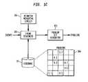
- FIG. 1Cshows details of one possible embodiment of event decoder 10
- FIG. 1Dshows details of one possible embodiment of codebook generator 12 .
- FIG. 2Ashows a causality graph of events which may occur in a system.
- FIG. 2Bshows the same information of FIG. 2A in an incidence matrix comprising rows and columns.
- FIG. 2Cshows a simplified causality graph in which certain nodes have been deleted.
- FIG. 2Dshows certain nodes of FIG. 2C having been designated as problems (rectangles) and symptoms (triangles).
- FIG. 2Eshows a further simplification to the graph of FIG. 2D .
- FIG. 2Fshows a correlation matrix corresponding to the simplified graph of FIG. 2E .
- FIG. 2Gshows a matrix in which redundant symptoms have been eliminated.
- FIGS. 3A and 3Bshow a process for generating an optimized codebook in accordance with various embodiments of the invention.
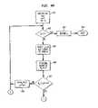
- FIGS. 4A and 4Bshow a process for decoding problems using a codebook in accordance with various embodiments of the invention.
- FIG. 5Ashows a well-formed correlation matrix for 6 problems producing 20 symptoms.
- FIG. 5Eshows a sample mismatch measure for use in a decoding process.
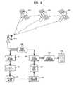
- FIG. 6is a block diagram showing how the principles of the present invention can be applied to a satellite system.
- FIG. 7is a block diagram showing how the principles of the present invention can be applied to medical diagnosis of patient symptoms.
- FIG. 8shows how a causality matrix may be generated either through a semi-automatic process or through a systematic process using event/propagation model specifications (such as GDME specifications which are compiled), and a specification of the system configuration.
- event/propagation model specificationssuch as GDME specifications which are compiled
- FIG. 9illustrates steps used by matrix generator 811 of FIG. 8 to generate a causality matrix.
- FIG. 1Ashows a networked computer system connected to apparatus 5 in accordance with the principles of the present invention.
- Three computer nodes 1 , 2 , and 3are shown connected to a computer network N.
- the network Nis interconnected with other networks (N 1 , N 2 , N 3 , N 4 ) via communication nodes, a bridge node 17 and a router node 18 .
- the phrase “network of computer nodes” as used herein and in the claimswill be understood to refer to both a network which only includes computer nodes and to a network which further includes communication nodes.
- Each computer nodemay also be connected to peripherals such as 1 a , 2 a , and 3 a – 3 c .
- two or more computer nodesmay be connected via an interface 4 .
- Each computer nodemay generate one or more signals on network N, or through other means, corresponding to symptoms in the system. Examples of symptoms for which signals may be generated could include power failure, peripheral failure, temperature limit exceeded, network interface error, adding a new address on the network, or the like. Of course, any conceivable type of symptom which can be detected could be generated.
- apparatus 5the networked computer system may be monitored and problems reported based on observed symptoms.
- Apparatus 5which may be implemented on a computer of any of various types, is connected to network N, although it may be connected to the system through any other means such as direct I/O connections to the various computer nodes or by a wireless link.
- Apparatus 5includes event detector 6 which receives and monitors events representing symptoms and determines that a particular event has occurred (for example, a power failure message received from one of the computer nodes). These events, generated by computer nodes 1 – 3 , may be transmitted by any suitable means, such as sending data packets over an Ethernet which are received by apparatus 5 .
- Apparatus 5also includes event decoder 10 which receives detected events from event detector 6 and, by way of codebook 11 , determines one or more “best fit” problems corresponding to the detected event.
- Codebook 11may be stored in a computer storage device such as a disk file or in computer memory, and event decoder 10 comprises means for reading values from codebook 11 . After determining the best fit problem, event decoder 10 causes report generator 13 to generate a report 14 which provides an indication of a problem for which corrective action might be taken.
- Report 14may be generated in any of various forms such as a message sent to computer systems responsible for automated handling of problems, a record of the problem logged in a storage device (such as a file or a database), a computer-generated printout, a computer display 15 , data sent to a software client 16 , indicators on a control panel, or the like. Additionally, the reported information may be displayed in alphanumeric or graphical form, or it may comprise a signal containing the reported information which may be further transmitted to another location.
- Codebook 11may be generated by codebook generator 12 in accordance with the principles of the invention as outlined in more detail herein.
- fileas used herein will be understood to include any computer accessible storage including memory, disk, or the like.
- causality matrix 9contains a mapping of system symptoms to likely problems, preferably with probabilities corresponding to each mapping.
- the likelihood that a reported power failure in one of the computer nodes is the result of a blown fusemight be assigned a probability of 0.25.
- causality matrix 9may be generated by manual means, it may be generated automatically using event capture 7 and event validation 8 based on events which are observed over a period of time, or it may be generated by interpreting a formal specification of an event model and an event propagation model in a specific domain, both described in more detail herein.
- the lattermay be performed by generating a causality matrix by compiling a formal language that specifies the event and propagation model into methods and data structures that interpret the models in a specific configuration. This process is described in more detail herein.
- Event capture 7 and event validation 8may be controlled interactively by way of control means C 1 and C 2 , respectively, such as through operator input using a suitable command stream.
- FIG. 1Billustrates a method for employing the principles of the present invention in various embodiments.
- a causality matrixis created, the matrix comprising a mapping of observable symptoms in the system to likely problems corresponding thereto.
- the causality matrixis made “well-formed” by eliminating redundant information in rows and columns.
- an optimal codebookis generated which further reduces the amount of information in the matrix; this optimal codebook may be tailored for a particular level of error tolerance or symptom loss as described in more detail herein.
- observable symptoms generated by the systemare monitored, and at step 24 these monitored symptoms are decoded into problems, preferably using a mismatch measure to determine their closeness to the observable symptoms contained in the optimized codebook.
- a reportis generated corresponding to the one or more likely problems decoded from the optimized codebook.
- the processmay then either repeat at step 23 , or the generated report can be fed to either step 20 or step 22 to refine the causality matrix or the codebook respectively.
- FIG. 1Cshows details of one possible embodiment for event decoder 10 .
- Codebook 30which represents the same element as codebook 11 of FIG. 1A , contains an illustrative set of numerical probability values shown as 30 M.
- Event sequencer 10 breceives events such as vectors of symptoms and, for each such vector, retrieves values from codebook 30 .
- Mismatch measuring circuit 10 ais used by event sequencer 10 b to compare symptom vectors with values contained in codebook 30 .
- the “best fit” matches between values contained in codebook 30 and incoming symptom vectorsare provided to problem set generator 10 c , which outputs a likely problem set.
- FIG. 1Dshows details of one possible embodiment for codebook generator 12 .
- Causality matrix 40which represents the same element as causality matrix 9 in FIG. 1A , contains an illustrative set of discrete probability values shown as 40 M.
- Optimized codebook 60which represents the same element as codebook 11 in FIG. 1A , contains an illustrative set of discrete probability values shown as 60 M.
- Well-formed matrix generator 12 areads values from causality matrix 40 and, through various operations described in more detail herein, removes redundant data from the matrix and generates well-formed causality matrix 50 as an intermediate product. In the illustrative example, rows 5 and 6 of causality matrix 40 M have been deleted as shown in 50 M.
- Optimizer 12 breads values from well-formed causality matrix 50 and, through the use of mismatch measuring circuit 12 c and a desired radius R, reduces the amount of information in well-formed causality matrix 50 to a smaller set which meets a given set of desirable criteria.
- Optimizer 12 bproduces optimized codebook 60 as an output, having illustrative values shown as 60 M.
- FIGS. 2A to 2Gshow one example of how codebook 11 can be generated from causality matrix 9 .
- FIG. 2Ashows a causality graph of events which may occur in the computer system being monitored by apparatus 5 .
- the causality graphcomprises a set of numbered nodes, each representing an event in the system, and directed edges (arrows) connecting these nodes, each representing a causality relationship between the events at the tail and head of the edge.
- event 1causes event 3 , which causes event 4 , which in turn causes event 5 , and so on.
- event 1may be a disk drive failure in a peripheral attached to one of the computer nodes in FIG. 1A .
- Event 3caused by event 1 , may be an error message generated by the computer to which the failed disk drive is attached, the error message indicating the detected disk drive failure.
- event 1can be classified as a problem (i.e., it can be fixed), while event 3 can be classified as a symptom caused by the problem.
- event 3might have other causes, such as event 5 , as indicated in FIG. 2A .
- FIG. 2Bshows the same information in the causality graph of FIG. 2A in the form of an incidence matrix comprising a plurality of rows and columns which define a plurality of cells, each cell corresponding to an intersection of one row and one column.
- Each cellcontains a value (in this example, either 0 or 1) indicating whether or not a particular event is caused by another event.
- event 3third column
- events 3 , 4 , and 7because these rows contain a “1” for the third column.
- the cell valuescan be any value which would indicate the probability that the given event causes a corresponding event.
- the information in the incidence matrix of FIG. 2Bcan be simplified by noting that certain events always occur in combination.
- the events ⁇ 3 , 4 , 5 ⁇form a correlated set (i.e., one cannot occur without the other), and they can therefore be combined into a single event 3 as illustrated in FIG. 2C whereby nodes 4 and 5 have been deleted.
- This first simplification of the informationis thus done by replacing “cycles” in the causality graph with single aggregate nodes.
- the information in FIGS. 2A to 2Gmay be stored in a computer memory or the like in various data structures, or it may be displayed graphically on a computer screen for manipulation by a human.
- this informationmay be represented and manipulated in various ways, and further elaboration is not required.
- Each node in the simplified causality graph of FIG. 2Cmay be designated as either a problem or a symptom.
- a problemis an event that requires handling, while a symptom is an event that may be observed.
- An eventcan be designated as both a problem and a symptom, or it may be neither.
- rectangleshave been used to designate nodes which are problems, and triangles have been used to designate nodes which are symptoms.
- event 1is a disk drive failure (problem)
- event 3is an I/O error message generated by the computer connected to the failed disk drive (symptom of the problem).
- node 8has been deleted from the causality graph of FIG. 2D in the simplified graph of FIG. 2E . All remaining nodes are now designated as either an observable symptom or a problem that requires handling.
- the information in the simplified graph of FIG. 2Ecan now be represented in a correlation matrix as shown in FIG. 2F .
- the matrix of FIG. 2Fcontains columns corresponding to the problems of FIG. 2E and rows corresponding to the observable symptoms of FIG. 2E .
- a symptomis correlated with a problem if there is a causal path leading from the problem to the symptom.
- problem 1leads to (directly or indirectly) symptoms 3 , 7 , 9 , and 10 .
- these rows of column 1are indicated with a “1” while remaining row 6 is indicated with a “0” because there is no causal relationship between problem 1 and symptom 6 .
- the correlation matrix of FIG. 2Fmay contain symptoms which do not contribute useful information for detecting problems, or it may contain problems that cannot be distinguished by the given symptoms, it is desirable to further reduce the correlation matrix to eliminate such non-informative rows and columns.
- the first simplificationis to eliminate identical rows, because such rows indicate that the respective sets of symptoms provide identical information about the problems. For example, rows 3 , 7 , 9 , and 10 of the correlation matrix in FIG. 2F contain identical information, and these redundant symptoms may be eliminated as shown in FIG. 2G and replaced with row 3 only.
- the second simplificationis to eliminate identical columns, because such columns indicate that the respective problems cannot be distinguished by the observed symptoms. Indistinguishable problems can be aggregated into a single abstract problem. This is particularly useful when a large collection of similar problems need to be handled in a similar manner. For example, various different problems with an Ethernet interface card (e.g., loose connector, defective collision-detection circuits) all lead to similar symptoms. The problem can therefore be generally abstracted as an “interface problem” and the correlation process will only identify that such a problem exists, but will not be able to determine which specific condition (loose connector or defective circuits) exists. Further resolution of the specific problem could then be pursued by running diagnostics.
- Ethernet interface carde.g., loose connector, defective collision-detection circuits
- problems 1 and 11 in FIG. 2Fhave been aggregated into a “problem 1 / 11 ” in FIG. 2G .
- the correlation matrix of FIG. 2Gis considered to be well formed because it has distinct rows and columns. Each column provides a distinct signature of the respective problem.
- a column vectorwill hereinafter be referred to as a “code” of the problem corresponding to the column representing the problem.
- a codebookis a set of symptoms whose respective rows in the correlation matrix provide a distinct code for every problem.
- the various data reductions described abovecan be used to convert a correlation matrix into such a codebook.
- the codebookmay still contain a very large number of symptoms which contribute little to detecting or identifying problems (although the example outlined above is, of course, small). Therefore, additional mechanisms are needed to reduce the size of codebooks while providing optimal identification of problems.
- One approach for further reducing the size of codebooksis to develop a measure of distance among codes and use this measure to determine the distinguishability among the codes. A process can then be used to generate codebooks that accomplish a desired level of distinguishability using a minimal set of symptoms.
- the Hamming distance between two codes p and qis the number of coordinates where the two codes are not similar.
- This distance between problems p and q relative to a set of symptoms S (rows)will be referred to as d s (p,q).
- This distancemeasures the distinguishability between the codes of the respective problems for a given set of symptoms.
- the distance of a problem p from an entire set of problems P relative to a set of symptoms Swill be designated as d s (p,P), which is the minimal distance between p and members of P for the given set of symptoms S.
- d s (p, ⁇ ⁇ )i.e., the distance of a problem p from an empty set, is infinite.
- the radius of a set of problems Pis the minimal distance between the codes of the set of problems P relative to a set of symptoms S.
- the radiusmeasures the minimal (worst case) distinguishability between the codes of P.
- an optimal codebookcan be generated by finding a minimal subset of the symptoms that provides an acceptable level of identification of the problems, where the radius provides a measure of the identification level.
- a codebook of a given radiusis minimal if none of its symptoms can be eliminated without decreasing its radius.
- the objectiveis to find a minimal set of symptoms S′ ⁇ S (codebook) such that r s .(P) ⁇ d.
- the creation of an optimal codebookmay be performed in a “preprocessing” stage, which allows one to trade off computation time in creating the codebook for faster execution time during a decoding stage using the optimized codebook.
- the process for generating an optimal codebook in accordance with the aforementioned objectiveswill now be described with reference to FIG. 3 .
- step 302a test is made to determine whether the problems covered by the codebook are identical to the problems covered by the well-formed correlation matrix. If all the problems are covered by the codebook S, the process continues to step 317 to generate the optimized codebook S by eliminating symptoms from S while maintaining the radius above the required one d. Accordingly, step 317 is executed in which the next symptom s (not already examined) is retrieved from S.
- step 318if there are no more symptoms, i.e., all the symptoms in S have been examined, the codebook S is considered to be complete and minimal in step 303 and the process terminates and exits at step 304 , the optimized codebook being represented by S. Otherwise, if there are more symptoms, the process continues to step 319 , in which the radius of the set of problems P relative to codebook S minus the symptom s is compared to the required distance d. If the radius is not smaller than d, the symptom s is removed from S in step 320 . In any case, the process iterates to step 317 . If in step 302 not all problems are covered by the codebook S, the process continues to step 305 .
- step 305the next problem p is selected from the problem set P ⁇ Q, and the Hamming distance between this problem and the problem set Q covered by the optimized codebook is determined in step 306 .
- Executing step 308indicates that the codebook S already distinguishes p from Q by an appropriate distance.
- step 309is executed, in which the next symptom s (not already covered in S) is retrieved from the well-formed correlation matrix.
- step 310if there are no more symptoms, this indicates that all the symptoms not included in optimized codebook S have been examined, and step 311 is executed.
- step 313the subset of problems Q′ of Q is determined in step 313 .
- Q′is the subset of problems of Q such that the Hamming distance of every problem q ⁇ Q′ from p relative to the codebook S, d s (p,q), is equal to the Hamming distance of p from the entire set of problems Q, d s (p,q). Then, s can be a candidate only if by adding it to the codebook S the distance of p from a member of Q′ increases.
- step 314a search for a problem q ⁇ Q′ such that d s ⁇ s ⁇ (p,q)>d s (p,q) is performed. If such q does not exist, the symptom s is ignored (step 315 ). Otherwise, s is considered to be a candidate for S in step 316 , and processing resumes at step 309 .
- the above processcan be used to generate an optimal codebook from a well-formed correlation matrix.
- the processis finite due to the specified restriction r(P) ⁇ d.
- the set Qequals the set P and all problems are covered by the optimal codebook S.
- the optimal codebook Ssatisfies the distinguishing criterion d ⁇ r s (P) and is minimal.
- the complexity of the processis polynomial in the number of problems and symptoms.
- the processcan be incrementally applied with minor variations to handle additional new problems by simply extending the codebook to cover the new problems. There is no need to regenerate the entire codebook. Similarly, if certain symptoms become unavailable, they may be replaced with new symptoms by extending the codebook rather than regenerating it. This flexibility to handle changes in the codebook may be important in an environment where the problems of interest and the observable symptoms can vary. Distance measures other than Hamming distances can, of course, be used, and the invention is not limited in this regard.
- GRAPH CAUSALITY MATRIX symptom node row problem node columndirected path from event to a matrix cell problem node weight on path probability (Correlation symbol) set of symptom nodes reachable code of a problem from a problem node viadirected paths.
- S(P)symptoms of P. size of difference among two sets Hamming distance among of nodes
- rMin ⁇
- mappings abovecan also be used to generate a codebook directly from a graph by mimicking the process for the causality matrix.
- direct generation of the codebookcan be performed by the following steps:
- a probabilistic correlation modelis a matrix which contains for each problem p (column) and each symptom s (row) the conditional probability that s will be caused by p. This is really just a special case of the general model outlined previously where the probabilities were 0 or 1. Where it is difficult to obtain accurate estimates of the probabilities, discrete probability values such as high (h), medium (m), or low (l) may be used to indicate relative probability levels. That is, the elements of the correlation matrix may take on values from the set ⁇ h,m,l ⁇ .
- Temporal correlations among eventsmay also be indicated by values which represent a time period from the occurrence of the problem until generation of the symptom. Additionally, temporal correlations among symptoms may also be specified. In either case, a discrete measure from the set comprising ⁇ l (long), m (medium), s (short), 0 (never) ⁇ may be used.
- the correlation matrixmay include pairs of the form ⁇ Pr, t) where Pr is a probability indication from ⁇ h,m,l ⁇ and t is a time indication from (l,m,s,0 ⁇ .
- Pris a probability indication from ⁇ h,m,l ⁇
- tis a time indication from (l,m,s,0 ⁇ .
- the pair (h,s) in the correlation matrixwould indicate that the respective problem may cause the symptom with high probability over a short time window.
- a generalized correlation modelmay be defined to include:
- the code of a problem pis the vector of indicator values of the respective correlation matrix column.
- the distance between two such codes p and qis given by the following function:
- d s (p,q)⁇ s ⁇ s ⁇ (p s ,q s )
- p sis the coordinate of p corresponding to the symptom s, that is, the component of the correlation matrix in column p and row s.
- the distance between two codes, determined using ⁇ H in the table above,is the number of coordinates where the vectors have different components.
- the factors 0 ⁇ , ( ⁇ )1measure the similarity between medium and low probability (respectively, high and medium probability).
- This distancereflects coordinates where one problem is very likely to show a symptom while the other problem is unlikely to show the symptom. Coordinates where symptoms provide uncertain signals are ignored.
- the codebook generation process as described abovewill yield a minimal one whose codes are sufficiently distinct in the sense of distance between probabilistic codes defined above.
- the optimal codebookcan be used to decode symptoms which occur during system operation and to generate reports indicating detected and/or identified problems (see FIG. 1A ).
- the event decoder 10 of FIG. 1Aclassifies a vector of observed symptoms into the most appropriate code. Generally, symptoms are either observed or not observed, but the principles of the invention are easily applied to probabilistic determinations where observations are uncertain.
- a codebookcontains 6 symptoms.
- symptomsmay be lost or generated spuriously, so it is necessary for the decoding process to find the “best fit” problem even though none matches exactly the set of symptoms.
- One method of finding the “best fit” problemis to use a mismatch measure.
- a mismatch measurecan be defined as a function ⁇ : ⁇ 0,1 ⁇ I ⁇ + which assigns to a symptom (1 if the symptom is observed, 0 if it is not observed) and a corresponding correlation indicator i, a measure of mismatch between the observation and a code.
- the value of ⁇ (1,i)measures the mismatch between an observation of a symptom and a code where it occurs with correlation i.
- ⁇ (0,i)measures the mismatch between the lack of observation of a symptom and a code where it occurs with correlation i.
- the codeexpects the symptom to occur (or not to occur) and it is observed (or is not observed), there is a perfect match between the observation and the code.
- Mismatch measuresmay be described using tables in a manner similar to distance measures. Columns represent correlation symbols, while rows represent observations ⁇ 0,1 ⁇ . For example, the mismatch measure for the deterministic model is given below:
- mismatch measurerepresents the degree to which the observed and absent symptoms of a match the code of p. It is expressly understood that the term “mismatch measure” can be more generally referred to as a correlation measure or correlation distance without limiting its application in the present invention. The above described tables can thus be replaced by measures of correlation (similarity) to produce die same results.
- a decoder for a correlation model over a codebook Scan be defined as a process that maps an observation a to the set of problems whose codes have minimal mismatch with a.
- a codebook Sa set of problems P with codes over S, and a mismatch measure m s , an input observation a over S will be decoded, and an output will be generated corresponding to all problems p that minimize m s over P.
- FIG. 4the decoding process will now be described in detail in accordance with the above objectives.
- step 401Q (the set of problems to be considered) is initialized to P, P* (the set of decoded problems) is initialized to the null set, and m* (the minimal mismatch) is initialized to infinity.
- step 402a test is made to see if the set of problems to be considered has been exhausted. If so, step 403 is executed, in which all decoded problems are returned and the process exits in step 404 .
- step 405a problem is selected from Q and the problem is removed from Q.
- step 406the mismatch m s (a,p) is determined between the observed vector a and the problem p as described previously.
- step 407the determined mismatch is compared with the current minimal mismatch m*. If the newly determined mismatch is less than the current minimal mismatch, then step 408 is executed.
- step 408a new value for m* is assigned corresponding to the newly determined mismatch, and the problem p corresponding thereto is inserted into P* (i.e., the decoded problem set). Processing then resumes at step 402 .
- step 407If, in step 407 , the determined mismatch is not less than the current minimum mismatch value, a test is performed in step 409 to determine whether the determined mismatch is equal to the current minimum mismatch value. If they are equal, step 410 is executed, in which the problem p is added to the decoded problem set P*. It will be noted that multiple problems could have the same degree of mismatch and thus more than one problem could be inserted into P* in this instance.
- step 409processing resumes at step 402 .
- the decoded problem set P*is generated as an output in step 403 .
- the complexity of the above processis determined by step 406 .
- the mismatch measurerequires additions of
- the processis suitable for executing in real-time and, due to the reduced complexity and amount of data in the optimized codebook, the amount of computation over other approaches is greatly reduced. Particularly in very large and complex systems, the increase in performance can be substantial.
- the decoding processcan be modified slightly to identify, instead of “best fit” matches for a given observation, codes which match the observation up to a particular level of tolerance from the “best” mismatch. That is, a level of tolerance T can be set and all codes that are within a mismatch of T above the minimum mismatch will result in the corresponding problem being output as part of the decoded problem set P*. To accomplish this, steps 407 and 409 of FIG. 4 would be modified slightly to compare m s (a,p) with m*+T rather than m*.
- the steps in FIG. 4determine the minimally mismatched codes that would explain a given observation vector.
- the measure of mismatch usedcan be selected to reflect a variety of considerations and sensitivities specific to a given system. Due to the simplicity of the decoding process (i.e., involving simple operations such as additions and comparisons), the process can be executed very fast and in real time.
- FIG. 5Ashows a well-formed deterministic correlation matrix (i.e., all problems cause certain symptoms with certainty) for 6 problems P producing 20 symptoms S.
- codebook S 2With the 5 symptoms shown in FIG. 5D , the number of possible non-trivial observations is 31, of which only 6 are exact codes. Considering first observations resulting from the loss of 1 symptom in the codes, since the distance among the codes in FIG. 5D is at least 2, none of these observations can be a code. This set includes the following 15 observations: ⁇ 11000, 10100, 01100, 00110, 01010, 01111, 10111, 11011, 11101, 11110, 10010, 00011, 00101, 00001, 10000 ⁇ . These observations will be decoded into the codes at distance 1 from which a symptom is lost. This means that at most two codes will be decoded from these observations.
- this setincludes the 10 observations ⁇ 00100, 00010, 01000, 10101, 10011, 11001, 101110, 01110, 01101, 01011 ⁇ .
- the first 3may be generated by multiple codes, while the remaining 7 may only be generated from the code for problem 3 by deleting two symptoms. That is, each of these 7 observations will be decoded as problem 3 .
- FIG. 6shows how the principles of the present invention can be applied in a system which includes satellites communicating with a ground station.
- elements 606 to 613perform functions identically or similar to those of elements 6 to 13 in FIG. 1A .
- a ground station 620communicates with a plurality of satellites 621 , 622 and 623 by way of radio wave propagation.
- Each satellitemay typically comprise numerous processing components including sensors and devices which may generate symptoms such as low power, device failures, and the like. These symptoms can be transmitted to ground station 629 , which is connected to event detector 606 .
- the inventiondecodes events which occur during system operation and generates a report 614 corresponding to the one or more likely problems in the system. Because the number of events in the system of satellites can be quite large and the relationships among events complex, the data reduction principles of the present invention can result in significant performance advantages over conventional approaches.
- the satellites shown in FIG. 6may comprise a telecommunication system, for example.
- elements 621 – 623may instead comprise ground-based telecommunication nodes having switches and multiplexors which may generate symptoms.
- FIG. 7shows how the principles of the present invention can be applied in medical diagnosis applications.
- Elements 706 to 713perform the same or similar functions as elements 6 to 13 of FIG. 1 .
- One or more sensors 720may receive symptoms from a patient such as temperature, blood pressure, chemical levels, breathing rate, and the like.
- a doctormay manually enter other symptoms through input means 721 , such as through a menu.
- These symptomscould include not only those directly observable such as skin color, pain locations and the like, but could also include derived symptoms such as partial diagnoses based on the doctor's own knowledge or suspicions.
- Symptoms from sensors 720 and input means 721are fed to event detector 706 in a manner similar to that for other embodiments of the invention. Based on the observed symptoms, the invention produces a report 714 or other indication of the likely diagnosis, such as on a graphics display or the like.
- the apparatus of FIG. 7may also be used to analyze financial market events by replacing sensors 720 with an appropriate data collection device (such as a computer program or other statistical filtering device) to compile prices, ratios, trends, etc. into events for event detector 706 .
- an input device suitable for receiving human-observable eventsmay be provided so that a market analyst may input such events.
- the decoding tablemay be generated in advance, and decoding becomes a simple and fast table lookup process. This is particularly useful when the code is efficient.
- the size of the lookup tablecould be 21
- the codescould admit significant perturbations while accomplishing unique decoding. This is entirely analogous to the design of error-correcting codes. With sufficient redundancy in the codebook, decoding can be very robust to lost or spuriously generated symptoms.
- the radiusis r, the number of observations that decode into a given code is approximately 2 r/2 , leading to a total of some
- Real-time correlation computationsare reduced significantly by preprocessing event knowledge to generate codebooks prior to real-time event detection and correlation. This is in contrast to typical event correlation systems based on artificial intelligence techniques which conduct indefinite searches during real time to correlate events. In extremely large and complex systems, the reduction in real-time processing requirements can significantly reduce the amount of hardware required and can result in faster problem diagnosis.
- the set of events to be monitoredcan be narrowed to only those that provide the highest information benefit, rather than arbitrarily monitoring all possible events, or an ad hoc set of events. This reduces the complexity of the correlation process and minimizes the waste of computer processing resources.
- the instrumentalities of the inventioncan be implemented with a relatively small set of code that can be operated on a single computer.
- causality matricesIn addition to creating causality matrices manually, they may be generated through the use of a formalized language which verifies various data relationships and creates a matrix, or they may be created semi-automatically using statistical analysis and filtering using well-known techniques. Thus, event capture 7 and event validation 8 shown in FIG. 1A may be used to generate causality matrix 9 using either approach shown in FIG. 8 , as described in more detail below.
- the left side of FIG. 8shows how events which result from event detector 6 (see FIG. 1A ) may be processed using elements 801 through 806 to generate causality matrix 807 (these elements also illustrate the process which may be used).
- the right side of FIG. 8shows how causality matrix 807 may be generated from an event model 809 , an event propagation model 810 , and a configuration specification 812 .
- the latter approachprovides significant benefits in that a formal, automatable process is provided for generating causality matrix 807 for a dynamically changing system from static event knowledge associated with the types of components in the system and the dynamic specification of a particular configuration.
- Either approachmay be implemented using computer software and corresponding data files, and the resulting causality matrix 807 may be stored in a storage device such as a computer disk for later access.
- a storage devicesuch as a computer disk for later access.
- events received from event detector 6are logged in event logger 801 .
- This elementmay time-stamp the event and record “what happened”; for example, a disk drive error in one of the networked computer nodes illustrated in FIG. 1A .
- These eventsmay be stored in an intermediate data file (not shown) for statistical analysis by element 802 .
- Statistical analysis 802analyzes the data produced by element 801 to identify correlations among events, and may be performed either in quasi-real time or in an off-line mode using historical data collected over a long period of time.
- Statistical analysis 802may be performed using any well-known method, such as multiple linear regression analysis, and a detailed explanation of these well-known methods is not provided here.
- the purpose of element 802is to identify correlations among events which are detected in the system (i.e., identify events that occur in pairs, where one event probably causes another event), and to store the correlation information into a data file 803 .
- a filter 804is applied to this data to remove weakly correlated data. This may be done by allowing a user to specify a particular correlation threshold or any other means to weed out weakly correlated events.
- the filtered datais then formatted into causality matrix 807 through the use of matrix generator 806 in accordance with the description of this matrix as previously described.
- Each of these operationscan be programmed easily using a digital computer and any suitable computer language, such as C, FORTRAN, or LISP.
- the GDME specifications shown in FIG. 8represent one possible embodiment of a formal language for specifying the event and propagation models. Such a language may be processed by a compiler 808 , such as a GDFME compiler which reads “statements” read from a file or entered by a user. Other possible embodiments include languages with a different syntax from that described herein, different data structures, graphical representations, or any other means of specifying the static information in event model 809 and propagation model 810 .
- Any particular system monitored using the principles of the present inventioncan be characterized by a domain consisting of a set of objects (hardware, software, communications or others) which can generate events. These objects within the domain will be called event source objects (ESOs), indicating that each such object can be the source of one or more events.
- ESOevent source objects
- Each ESOcan be characterized as belonging to a particular class, and each can be related to other ESOs via certain relationships.
- a power supply objectmay be related to a CPU board object via the relationship “provides-power-to”. Events may propagate among such relationships.
- a problem event in the power supplymay cause symptom events (as well as problem events) at the CPU board and other objects to which it “provides-power-to”.
- the information required to analyze eventscan be divided into two kinds:
- This knowledgemay comprise an event model and an event propagation model which can be provided by the designer of each component at design time.
- the class to which an ESO belongsdetermines the set of exceptional events (problems) that may occur in the component, the local symptoms they cause, and the probability that they may cause these local symptoms. This information constitutes the event model for the class.
- the class to which an ESO belongsalso may determine the set of relationships that ESOs of the class may participate in. Events may propagate along relationships to and from related ESOS. For example, the knowledge of various events of a power supply component and the manner in which these events may cause events occurring at ESOs to which the component “provides-power-to”. This knowledge is typically generic to various types (classes) of ESOs. The specification of which class events may propagate along which relationships constitutes the event propagation model for the class.
- a given domainmay include 14 workstations, each of which contains an instance of a power supply object and of various boards which this specific power supply object “provides-power-to”
- This datais assumed to be organized into a configuration specification for the particular domain, illustrated by element 812 in FIG. 8 .
- Any data representationmay be used to store this data, such as a memory data structure, a file, an object-oriented database, or others.
- Matrix generator 811generates causality matrix 807 by interpreting event and propagation models 809 and 810 , respectively, in a domain specified by configuration specification 812 . This process may be performed either with compiler 808 using compilable statements or specifications (as described in more detail herein), or directly from even model 809 and propagation model 810 . The interpretation may be performed as follows:
- step (b)Determine the causality closure. For every event in the set determined in step (a) above, the causality closure is the union of all observable events the event may cause and the probability it may cause each of them. This causality closure may be determined through the following recursive steps:
- GDME specificationsmay be input to compiler 808 in FIG. 8 in various embodiments of the invention as described in more detail below.
- alternative forms of specificationsmay be used, such as graphical representations, and the invention is not intended to be limited in this regard.
- the GDME specificationsmay comprise the following compilable statements input to compiler 808 :
- INTERFACE statementdefines a class of event source objects and provides the start of a definition block. All statements between an INTERFACE statement and an END statement are associated with a definition block.
- a preferred statement syntaxis:
- class-nameis alphanumeric name of the new type of objects being defined
- parent-class-nameis an is alphanumeric name of the generic type of objects the new class inherits from.
- the parent classmust be either a “basic” class of the data model or a previously defined class.
- ATTRIBUTE statementspecifies an attribute, property and/or real-time measurement of an object.
- a preferred syntax for this statementis:
- EVENT statementspecifies an event that might be generated by objects in the class. Each event is specified by an EVENT statement as a Boolean expression on properties of the class or as a user function.
- a preferred statement syntaxis:
- IMPORT statementspecifies an event that an object in the class may import from another object.
- the eventmay propagate from an object of this class to other objects via one of the relationships that exists between the respective objects.
- a preferred statement syntax for this statementis:
- CAUSALITY statementspecifies a problem which may cause a set of observable events in the instances of the class. Observable events are those specified by an EVENT or IMPORT statement.
- a preferred syntaxis:
- EXPORT statementgroups sets of events into a single abstract event. Only events specified by an export statement are exported to the external world outside the class instance.
- a preferred syntax for this statementis:
- END statementterminates each definition block; each END statement should have a corresponding INTERFACE statement.
- a preferred syntaxis:
- GDME specification statementsspecify event knowledge associated with each object class (EVENT statements); the events that may occur in objects of the class and the symptoms that each such problem may cause (CAUSALITY statements); the events that may propagate to objects of the class from other related objects (IMPORT statements), and the events that can be externally observed in objects of the class (EXPORT statements).
- EVENT statementsthe events that may occur in objects of the class and the symptoms that each such problem may cause
- CAUSALITY statementsthe events that may propagate to objects of the class from other related objects
- IMPORT statementsthe events that can be externally observed in objects of the class
- GDME statementscomprising a plurality of the above statements are entered by a user into GDME compiler 808 .
- the statementsmay be tailored for the particular system being monitored and the specific classes, attributes, probabilities and other parameters will be selected according to the particular type of system.
- GDME compiler 808which may be constructed using the normal parsers and other well-known components in the software engineering field details of which are not provided here, generates event model 809 and propagation model 810 for each ESO class. These models are used by matrix generator 811 to analyze the events and causality associated with a specific domain described by the collection of entities and relationships stored in configuration specification 812 .
- Event model 809for an embodiment using a formal GDME event model, is a data structure comprising, in various preferred embodiments, three things:
- a list of problems associated with a classFor each problem, a list of events it may cause is included, each specifying the probability of this causality. This list is generated by compiler 808 from the CAUSALITY statements.
- a list of aggregated events associated with a classEach aggregate event has a name and a method to evaluate it. An aggregate event holds if any of the events it aggregates holds. This list is generated by compiler 808 from the EXPORT statements.
- Propagation model 810is a data structure comprising a list of all relationships associated with a class. It may additionally contain methods that are generated for determining the closure of the events that may propagate to other objects. This information may be generated by compiler 808 from the IMPORT statements.
- Matrix generator 811which differs from matrix generator 806 , generates causality matrix 807 from event model 809 , propagation model 810 , and configuration specification 812 using steps illustrated in FIG. 9 .
- matrix generator 811first determines the set of problems as the union of all the problems of all the ESOs in the domain. These are determined by the class of each ESO recorded in event model 809 and appearing in configuration specification 812 ( FIG. 8 ).
- matrix generator 811determines the set of symptoms in the domain as the union of all the symptoms of all the entities in the domain.
- each element of the causality matrixis generated using the direct causality stored in event model 809 , and using the indirect causality (events imported from other objects via relationships) by using the transitive closure of causality propagation using propagation model 810 .
- the transitive closuremay be determined via methods generated by compiler 808 , or by other means. These methods encapsulate the event propagation model and use the configuration specification to infer the possible paths for propagation of events required in computing the closure.
- the resulting causality matrix 904is used to generate an efficient codebook as described previously with relation to FIG. 1A .
- the inventionmay be practiced by distributing the decoding process across a number of computers, such that a complex system domain is partitioned into smaller domains, each domain having a local event correlator. Event correlators for the different domains may operate concurrently and interact with one another to selectively import/export events from one another. Numbered steps in the appended method claims should not be considered as limiting the particular order in which the claimed steps are practiced.
Landscapes
- Engineering & Computer Science (AREA)
- General Engineering & Computer Science (AREA)
- Theoretical Computer Science (AREA)
- Computer Hardware Design (AREA)
- Quality & Reliability (AREA)
- Physics & Mathematics (AREA)
- General Physics & Mathematics (AREA)
- Debugging And Monitoring (AREA)
- Alarm Systems (AREA)
- Mobile Radio Communication Systems (AREA)
Abstract
Description
- (1) a working memory which represents knowledge of the current state of the system being monitored; and
- (2) a rule base which contains expert knowledge in the form of “if-then” or “condition-action” rules. The condition part of each rule determines whether the rule can be applied based on the current state of the working memory; the action part of a rule contains a conclusion which can be drawn from the rule when the condition is satisfied.
| GRAPH | CAUSALITY MATRIX | ||
| symptom node | row | ||
| problem node | column | ||
| directed path from event to a | matrix cell | ||
| problem node | |||
| weight on path | probability | ||
| (Correlation symbol) | |||
| set of symptom nodes reachable | code of a problem | ||
| from a problem node viadirected | |||
| paths. S(P) = symptoms of P. | |||
| size of difference among two sets | Hamming distance among | ||
| of nodes |S(p1) Δ S(p2)| | codes | ||
| a minimal difference set among | radius | ||
| symptoms set of two problems. | |||
| r = Min{|S(p1) Δ S(p2)|; p1, p2} | |||
- a set of problem events P and a set of symptom events S
- a set of correlation indicators I
- a correlation matrix whose columns correspond to members of P, whose rows correspond to members of S, and whose elements are indicators from I.
- a distance measure δ:IXI→+ where
 + is the set of non-negative real numbers. This measure δ provides the distance (a similarity measure) between two correlation indicators.
| 0 | 1 | |
| 0 | 0 | 1 |
| 1 | 1 | 0 |
| δ | l | m | |||
| l | |||||
| 0 | α | 1 | |||
| m | 0 | ||||
| h | |||||
| 1 | 0 | ||||
p=(l,l,h,m,m,h)
q=(m,l,m,h,l,l)
d(p,q)=δ(l,m)+δ(l,l)+δ(h,m)+δ(m,h)+δ(m,l)+δ(h,l)=0.5+0+0.5+0.5+0.5+1=3.
d(p,q)=0+0+0+0+0+1=1.

| 0 | 1 | |
| 0 | 0 | |
| 1 | 0 | |
| δ | l | m | |||
| 0 | 0 | 0 | |||
| 1 | 0 | 0 | |||
ms(a,p)=Σsεs∂(as,ps)
- where attribute-name is an alphanumeric name of an attribute which is unique within the scope of the definition block, and attribute-type is the one of the pre-defined set of basic types.
- where event-name is an alphanumeric name of an event unique within the scope of the definition block, description is quoted free text that describes the event and/or associates an action with it (intended for presentation to human operators), and expression is either a Boolean expression in terms of the object's attributes and events or a function name to be used to detect the event.
- FROM class-name VIA relationship-name
- WHERE imported-event-name;
- where event-name is an alphanumeric name associated with the imported event used to uniquely identify the event within the scope of the definition block; description is a quoted free text string that describes the event and/or associates an action with it (a programmed action or one intended to be presented to human operators); class-name is an alphanumeric name of the class from which the following events are imported; relationship-name is an alphanumeric name of one of the relationship attributes of this class; and imported-event-name is an alphanumeric name of an event being imported from the specified class.
- where problem-name is an alphanumeric name of a possible problem with an object of the class; description is a quoted free text string that describes the problem and/or associates an action with it (a programmed action or one intended to be presented to human operators); symptom is an alphanumeric name of an observable event specified by either an EVENT of IMPORT statement; and probability may be l (low) m (medium), or h (high).
- IS event-name, . . . , event-name;
- where aggregate-name is an alphanumeric name of an abstract problem exported by the object, description is a quoted free text string that describes the problem and/or associates an action with it (a programmed action or one intended to be presented to human operators); and event-name is an alphanumeric name of an event that is specified by an EVENT, IMPORT or PROBLEM statement.
- where class-name is an alphanumeric name of the class being defined in the INTERFACE statement.
Claims (30)
Priority Applications (3)
| Application Number | Priority Date | Filing Date | Title |
|---|---|---|---|
| US11/034,192US7003433B2 (en) | 1994-05-25 | 2005-01-12 | Apparatus and method for event correlation and problem reporting |
| US11/263,689US7107185B1 (en) | 1994-05-25 | 2005-11-01 | Apparatus and method for event correlation and problem reporting |
| US11/494,250US7337090B1 (en) | 1994-05-25 | 2006-07-27 | Apparatus and method for event correlation and problem reporting |
Applications Claiming Priority (7)
| Application Number | Priority Date | Filing Date | Title |
|---|---|---|---|
| US08/249,282US5528516A (en) | 1994-05-25 | 1994-05-25 | Apparatus and method for event correlation and problem reporting |
| US46575495A | 1995-06-06 | 1995-06-06 | |
| US08/679,443US5661668A (en) | 1994-05-25 | 1996-07-12 | Apparatus and method for analyzing and correlating events in a system using a causality matrix |
| US08/893,263US6249755B1 (en) | 1994-05-25 | 1997-07-15 | Apparatus and method for event correlation and problem reporting |
| US80976901A | 2001-03-16 | 2001-03-16 | |
| US10/400,718US6868367B2 (en) | 1994-05-25 | 2003-03-27 | Apparatus and method for event correlation and problem reporting |
| US11/034,192US7003433B2 (en) | 1994-05-25 | 2005-01-12 | Apparatus and method for event correlation and problem reporting |
Related Parent Applications (1)
| Application Number | Title | Priority Date | Filing Date |
|---|---|---|---|
| US10/400,718ContinuationUS6868367B2 (en) | 1994-05-25 | 2003-03-27 | Apparatus and method for event correlation and problem reporting |
Related Child Applications (1)
| Application Number | Title | Priority Date | Filing Date |
|---|---|---|---|
| US11/263,689ContinuationUS7107185B1 (en) | 1994-05-25 | 2005-11-01 | Apparatus and method for event correlation and problem reporting |
Publications (2)
| Publication Number | Publication Date |
|---|---|
| US20050137832A1 US20050137832A1 (en) | 2005-06-23 |
| US7003433B2true US7003433B2 (en) | 2006-02-21 |
Family
ID=22942800
Family Applications (5)
| Application Number | Title | Priority Date | Filing Date |
|---|---|---|---|
| US08/249,282Expired - LifetimeUS5528516A (en) | 1994-05-25 | 1994-05-25 | Apparatus and method for event correlation and problem reporting |
| US08/679,443Expired - LifetimeUS5661668A (en) | 1994-05-25 | 1996-07-12 | Apparatus and method for analyzing and correlating events in a system using a causality matrix |
| US08/893,263Expired - LifetimeUS6249755B1 (en) | 1994-05-25 | 1997-07-15 | Apparatus and method for event correlation and problem reporting |
| US10/400,718Expired - LifetimeUS6868367B2 (en) | 1994-05-25 | 2003-03-27 | Apparatus and method for event correlation and problem reporting |
| US11/034,192Expired - LifetimeUS7003433B2 (en) | 1994-05-25 | 2005-01-12 | Apparatus and method for event correlation and problem reporting |
Family Applications Before (4)
| Application Number | Title | Priority Date | Filing Date |
|---|---|---|---|
| US08/249,282Expired - LifetimeUS5528516A (en) | 1994-05-25 | 1994-05-25 | Apparatus and method for event correlation and problem reporting |
| US08/679,443Expired - LifetimeUS5661668A (en) | 1994-05-25 | 1996-07-12 | Apparatus and method for analyzing and correlating events in a system using a causality matrix |
| US08/893,263Expired - LifetimeUS6249755B1 (en) | 1994-05-25 | 1997-07-15 | Apparatus and method for event correlation and problem reporting |
| US10/400,718Expired - LifetimeUS6868367B2 (en) | 1994-05-25 | 2003-03-27 | Apparatus and method for event correlation and problem reporting |
Country Status (6)
| Country | Link |
|---|---|
| US (5) | US5528516A (en) |
| EP (1) | EP0760939B1 (en) |
| AT (1) | ATE208064T1 (en) |
| AU (1) | AU2599495A (en) |
| DE (1) | DE69523588T2 (en) |
| WO (1) | WO1995032411A1 (en) |
Cited By (27)
| Publication number | Priority date | Publication date | Assignee | Title |
|---|---|---|---|---|
| US20050097146A1 (en)* | 2003-08-21 | 2005-05-05 | Konstantinou Alexander V. | Methods and systems for autonomously managing a network |
| US20060097718A1 (en)* | 2004-10-08 | 2006-05-11 | Schlicker Darrell E | Local feature characterization using quasistatic electromagnetic sensors |
| US20060287843A1 (en)* | 2005-05-30 | 2006-12-21 | Omron Corporation | Process management apparatus, and process management method |
| US20080062885A1 (en)* | 2006-09-12 | 2008-03-13 | Microsoft Corporation | Major problem review and trending system |
| US20080178131A1 (en)* | 2006-09-25 | 2008-07-24 | Kabushiki Kaisha Toshiba | Testing method and method for manufacturing an electronic device |
| US20080188972A1 (en)* | 2006-10-11 | 2008-08-07 | Fisher-Rosemount Systems, Inc. | Method and System for Detecting Faults in a Process Plant |
| US7430495B1 (en) | 2006-12-13 | 2008-09-30 | Emc Corporation | Method and apparatus for representing, managing, analyzing and problem reporting in home networks |
| US7464132B1 (en)* | 2002-06-12 | 2008-12-09 | Emc Corporation | Method and apparatus for reference model change generation in managed systems |
| US20080313118A1 (en)* | 2007-06-13 | 2008-12-18 | International Business Machines Corporation | Method and apparatus for component association inference, failure diagnosis and misconfiguration detection based on historical failure data |
| US7805136B1 (en) | 2006-04-06 | 2010-09-28 | Sprint Spectrum L.P. | Automated form-based feedback of wireless user experiences accessing content, e.g., web content |
| US20100249551A1 (en)* | 2009-03-31 | 2010-09-30 | Nelicor Puritan Bennett LLC | System And Method For Generating Corrective Actions Correlated To Medical Sensor Errors |
| US7836156B1 (en) | 2008-03-31 | 2010-11-16 | Emc Corporation | Method and apparatus for analyzing network infrastructure |
| WO2013010253A1 (en)* | 2011-07-15 | 2013-01-24 | Inetco Systems Limited | Method and system for monitoring performance of an application system |
| US20130080624A1 (en)* | 2011-09-26 | 2013-03-28 | Hitachi, Ltd. | Management computer and method for root cause analysis |
| US8510149B1 (en)* | 2008-05-27 | 2013-08-13 | Abb Research Ltd. | Method of constructing causality network graphs and visual inference presentations for business rule applications |
| US20130275812A1 (en)* | 2012-04-16 | 2013-10-17 | Ruth Bernstein | Determining root cause |
| US20140122691A1 (en)* | 2012-10-25 | 2014-05-01 | Hewlett-Packard Development Company, L.P. | Determining root causes of network issues |
| US8812542B1 (en) | 2012-03-30 | 2014-08-19 | Emc Corporation | On-the-fly determining of alert relationships in a distributed system |
| US8832498B1 (en) | 2012-07-30 | 2014-09-09 | Emc Corporation | Scalable codebook correlation for cloud scale topology |
| US8856257B1 (en) | 2012-06-29 | 2014-10-07 | Emc Corporation | Sending alerts from cloud computing systems |
| US9262719B2 (en) | 2011-03-22 | 2016-02-16 | Patrick Soon-Shiong | Reasoning engines |
| US9413685B1 (en) | 2012-06-28 | 2016-08-09 | Emc Corporation | Method and apparatus for cross domain and cross-layer event correlation |
| US9736046B1 (en) | 2013-05-30 | 2017-08-15 | EMC IP Holding Company LLC | Path analytics using codebook correlation |
| US10229026B1 (en) | 2007-11-17 | 2019-03-12 | EMC IP Holding Company LLC | Method and apparatus for providing environmental management in distributed system data centers |
| US10346566B2 (en) | 2015-12-29 | 2019-07-09 | EMC IP Holding Company LLC | Method and device for simulating disk drive |
| US10693711B1 (en) | 2018-03-15 | 2020-06-23 | EMC IP Holding Company LLC | Real-time event correlation in information networks |
| US11233709B2 (en) | 2011-07-15 | 2022-01-25 | Inetco Systems Limited | Method and system for monitoring performance of an application system |
Families Citing this family (534)
| Publication number | Priority date | Publication date | Assignee | Title |
|---|---|---|---|---|
| US10361802B1 (en) | 1999-02-01 | 2019-07-23 | Blanding Hovenweep, Llc | Adaptive pattern recognition based control system and method |
| US5692186A (en)* | 1994-01-20 | 1997-11-25 | Fujitsu Limited | Production system, hierarchical network and method of node control of hierarchical network |
| US5528516A (en)* | 1994-05-25 | 1996-06-18 | System Management Arts, Inc. | Apparatus and method for event correlation and problem reporting |
| JPH0855029A (en)* | 1994-08-09 | 1996-02-27 | Komatsu Ltd | Reasoning device |
| JP3265131B2 (en)* | 1994-08-29 | 2002-03-11 | 日本電気株式会社 | Event generation distribution method |
| US6925397B2 (en) | 1994-11-29 | 2005-08-02 | Warren Rogers Associates | Meter calibration accuracy |
| US5757664A (en)* | 1996-06-04 | 1998-05-26 | Warren Rogers Associates, Inc. | Method and apparatus for monitoring operational performance of fluid storage systems |
| JPH08278890A (en)* | 1995-04-05 | 1996-10-22 | Sharp Corp | Evolutionary adaptive inference knowledge extraction device and point-of-sale data analysis device using the device |
| US5765026A (en)* | 1995-06-16 | 1998-06-09 | International Business Machines Corporation | Method for implementing state machine using link lists by dividing each one of the combinations into an initial section, an immediate section, and a final section |
| US6122759A (en)* | 1995-10-10 | 2000-09-19 | Lucent Technologies Inc. | Method and apparatus for restoration of an ATM network |
| US5872911A (en)* | 1995-12-29 | 1999-02-16 | Mci Communications Corporations | Method and system of service impact analysis in a communications network |
| US6017143A (en)* | 1996-03-28 | 2000-01-25 | Rosemount Inc. | Device in a process system for detecting events |
| US6704686B2 (en)* | 1999-02-08 | 2004-03-09 | Geoffrey M. Jacquez | Method for measuring a degree of association for dimensionally referenced data |
| US6539267B1 (en) | 1996-03-28 | 2003-03-25 | Rosemount Inc. | Device in a process system for determining statistical parameter |
| US7623932B2 (en) | 1996-03-28 | 2009-11-24 | Fisher-Rosemount Systems, Inc. | Rule set for root cause diagnostics |
| US7085610B2 (en) | 1996-03-28 | 2006-08-01 | Fisher-Rosemount Systems, Inc. | Root cause diagnostics |
| US8290721B2 (en) | 1996-03-28 | 2012-10-16 | Rosemount Inc. | Flow measurement diagnostics |
| US7254518B2 (en) | 1996-03-28 | 2007-08-07 | Rosemount Inc. | Pressure transmitter with diagnostics |
| US7949495B2 (en) | 1996-03-28 | 2011-05-24 | Rosemount, Inc. | Process variable transmitter with diagnostics |
| US7630861B2 (en) | 1996-03-28 | 2009-12-08 | Rosemount Inc. | Dedicated process diagnostic device |
| AU2422797A (en)* | 1996-03-28 | 1997-10-17 | Bio-Analytics, Inc. Doing Business As Biomedware | Method for measuring a degree of association for dimensionally referenced data |
| US6654697B1 (en) | 1996-03-28 | 2003-11-25 | Rosemount Inc. | Flow measurement with diagnostics |
| US6907383B2 (en) | 1996-03-28 | 2005-06-14 | Rosemount Inc. | Flow diagnostic system |
| KR100274951B1 (en) | 1996-05-16 | 2000-12-15 | 윤종용 | Fault translation method and device of base station for digital cellular system |
| US6909986B2 (en)* | 1996-06-04 | 2005-06-21 | Warren Rogers Associates, Inc. | Method and apparatus for monitoring operational performance of fluid storage systems |
| US6934644B2 (en)* | 1996-06-04 | 2005-08-23 | Warren Rogers Associates, Inc. | Method and apparatus for monitoring operational performance of fluid storage systems |
| US6691061B1 (en) | 1996-06-04 | 2004-02-10 | Warren Rogers Associates, Inc. | Method and apparatus for monitoring operational performance of fluid storage systems |
| FI104599B (en)* | 1996-08-29 | 2000-02-29 | Nokia Networks Oy | Storage of transactions in a service database system |
| US5798950A (en)* | 1996-10-31 | 1998-08-25 | International Business Machines Corporation | Method and apparatus for estimating durations of activities in forming a current system, based on past durations of activities in forming past systems |
| US6434504B1 (en) | 1996-11-07 | 2002-08-13 | Rosemount Inc. | Resistance based process control device diagnostics |
| US6449574B1 (en) | 1996-11-07 | 2002-09-10 | Micro Motion, Inc. | Resistance based process control device diagnostics |
| US6519546B1 (en) | 1996-11-07 | 2003-02-11 | Rosemount Inc. | Auto correcting temperature transmitter with resistance based sensor |
| US6601005B1 (en) | 1996-11-07 | 2003-07-29 | Rosemount Inc. | Process device diagnostics using process variable sensor signal |
| US6754601B1 (en) | 1996-11-07 | 2004-06-22 | Rosemount Inc. | Diagnostics for resistive elements of process devices |
| JPH10222493A (en)* | 1997-02-06 | 1998-08-21 | Kokusai Denshin Denwa Co Ltd <Kdd> | Mutual causality analysis system |
| DE19707173C5 (en)* | 1997-02-22 | 2006-06-14 | Voith Siemens Hydro Power Generation Gmbh & Co. Kg | Machine diagnostic system and method for condition-based operation monitoring of a machine |
| DE19723079C1 (en) | 1997-06-02 | 1998-11-19 | Bosch Gmbh Robert | Fault diagnosis device for automobile |
| JPH1185853A (en)* | 1997-09-01 | 1999-03-30 | Hitachi Ltd | Disaster recovery response system |
| US6807583B2 (en)* | 1997-09-24 | 2004-10-19 | Carleton University | Method of determining causal connections between events recorded during process execution |
| DE19742448C1 (en)* | 1997-09-26 | 1998-12-17 | Daimler Benz Ag | Diagnostic module for electric automation circuits for overall system diagnosis |
| US6418469B1 (en)* | 1997-09-30 | 2002-07-09 | Compaq Information Technologies Group, L.P. | Managing conditions in a network |
| AU9795598A (en) | 1997-10-13 | 1999-05-03 | Rosemount Inc. | Communication technique for field devices in industrial processes |
| US6047279A (en)* | 1997-11-17 | 2000-04-04 | Objective Systems Integrators, Inc. | System and method for automatic network management support using artificial intelligence |
| JP3507681B2 (en)* | 1998-01-08 | 2004-03-15 | インターナショナル・ビジネス・マシーンズ・コーポレーション | Information processing method, information processing apparatus, information processing system, and storage medium storing program for controlling information processing apparatus |
| US6108800A (en)* | 1998-02-10 | 2000-08-22 | Hewlett-Packard Company | Method and apparatus for analyzing the performance of an information system |
| US6311175B1 (en) | 1998-03-06 | 2001-10-30 | Perot Systems Corp. | System and method for generating performance models of complex information technology systems |
| US6393387B1 (en) | 1998-03-06 | 2002-05-21 | Perot Systems Corporation | System and method for model mining complex information technology systems |
| US6393386B1 (en) | 1998-03-26 | 2002-05-21 | Visual Networks Technologies, Inc. | Dynamic modeling of complex networks and prediction of impacts of faults therein |
| DE19850122A1 (en) | 1998-04-17 | 1999-10-28 | Siemens Ag | Automatic configuration arrangement for technical object testing arrangement e.g. for electric motors |
| US6553403B1 (en)* | 1998-06-03 | 2003-04-22 | International Business Machines Corporation | System, method and computer program product for monitoring in a distributed computing environment |
| JP2000050123A (en)* | 1998-07-27 | 2000-02-18 | Sony Corp | Image pickup device, navigation device, ic card and method for displaying still image |
| DE19836347C2 (en) | 1998-08-11 | 2001-11-15 | Ericsson Telefon Ab L M | Fault-tolerant computer system |
| US6321338B1 (en)* | 1998-11-09 | 2001-11-20 | Sri International | Network surveillance |
| US6611775B1 (en) | 1998-12-10 | 2003-08-26 | Rosemount Inc. | Electrode leakage diagnostics in a magnetic flow meter |
| US6615149B1 (en) | 1998-12-10 | 2003-09-02 | Rosemount Inc. | Spectral diagnostics in a magnetic flow meter |
| US6018732A (en)* | 1998-12-22 | 2000-01-25 | Ac Properties B.V. | System, method and article of manufacture for a runtime program regression analysis tool for a simulation engine |
| US6550055B1 (en)* | 1998-12-29 | 2003-04-15 | Intel Corp. | Method and apparatus for cheating an information report resulting from a diagnostic session |
| US6724729B1 (en) | 1998-12-30 | 2004-04-20 | Finisar Corporation | System analyzer and method for synchronizing a distributed system |
| US6446136B1 (en)* | 1998-12-31 | 2002-09-03 | Computer Associates Think, Inc. | System and method for dynamic correlation of events |
| US6393586B1 (en) | 1999-02-04 | 2002-05-21 | Dell Usa, L.P. | Method and apparatus for diagnosing and conveying an identification code in post on a non-booting personal computer |
| US6629106B1 (en)* | 1999-02-26 | 2003-09-30 | Computing Services Support Solutions, Inc. | Event monitoring and correlation system |
| NO315100B1 (en) | 1999-12-03 | 2003-07-07 | Ericsson Telefon Ab L M | Analysis of computer networks |
| US6636771B1 (en) | 1999-04-02 | 2003-10-21 | General Electric Company | Method and system for analyzing continuous parameter data for diagnostics and repairs |
| US6336065B1 (en) | 1999-10-28 | 2002-01-01 | General Electric Company | Method and system for analyzing fault and snapshot operational parameter data for diagnostics of machine malfunctions |
| US6622264B1 (en) | 1999-10-28 | 2003-09-16 | General Electric Company | Process and system for analyzing fault log data from a machine so as to identify faults predictive of machine failures |
| US6947797B2 (en)* | 1999-04-02 | 2005-09-20 | General Electric Company | Method and system for diagnosing machine malfunctions |
| US6463528B1 (en)* | 1999-04-20 | 2002-10-08 | Covad Communications Group, Inc. | Method and apparatus for simplifying the configuration of several models of customer premise equipment |
| US6707795B1 (en)* | 1999-04-26 | 2004-03-16 | Nortel Networks Limited | Alarm correlation method and system |
| US6393559B1 (en) | 1999-04-30 | 2002-05-21 | Dell Usa, L.P. | Method and computer for self-healing BIOS initialization code |
| US6785636B1 (en)* | 1999-05-14 | 2004-08-31 | Siemens Corporate Research, Inc. | Fault diagnosis in a complex system, such as a nuclear plant, using probabilistic reasoning |
| US6615259B1 (en) | 1999-05-20 | 2003-09-02 | International Business Machines Corporation | Method and apparatus for scanning a web site in a distributed data processing system for problem determination |
| AU5156800A (en) | 1999-05-24 | 2000-12-12 | Aprisma Management Technologies, Inc. | Service level management |
| US6654914B1 (en)* | 1999-05-28 | 2003-11-25 | Teradyne, Inc. | Network fault isolation |
| US6467052B1 (en) | 1999-06-03 | 2002-10-15 | Microsoft Corporation | Method and apparatus for analyzing performance of data processing system |
| US6356191B1 (en) | 1999-06-17 | 2002-03-12 | Rosemount Inc. | Error compensation for a process fluid temperature transmitter |
| US7010459B2 (en) | 1999-06-25 | 2006-03-07 | Rosemount Inc. | Process device diagnostics using process variable sensor signal |
| US6473710B1 (en) | 1999-07-01 | 2002-10-29 | Rosemount Inc. | Low power two-wire self validating temperature transmitter |
| US6910135B1 (en)* | 1999-07-07 | 2005-06-21 | Verizon Corporate Services Group Inc. | Method and apparatus for an intruder detection reporting and response system |
| ATE284021T1 (en)* | 1999-07-09 | 2004-12-15 | Warren Rogers Associates Inc | METHOD AND APPARATUS FOR MONITORING THE OPERATING PERFORMANCE OF LIQUID STORAGE SYSTEMS |
| US6505517B1 (en) | 1999-07-23 | 2003-01-14 | Rosemount Inc. | High accuracy signal processing for magnetic flowmeter |
| US7783507B2 (en)* | 1999-08-23 | 2010-08-24 | General Electric Company | System and method for managing a fleet of remote assets |
| US6263265B1 (en) | 1999-10-01 | 2001-07-17 | General Electric Company | Web information vault |
| US20110208567A9 (en)* | 1999-08-23 | 2011-08-25 | Roddy Nicholas E | System and method for managing a fleet of remote assets |
| US7046929B1 (en)* | 1999-08-24 | 2006-05-16 | Ciena Corporation | Fault detection and isolation in an optical network |
| US6701274B1 (en) | 1999-08-27 | 2004-03-02 | Rosemount Inc. | Prediction of error magnitude in a pressure transmitter |
| US7263558B1 (en) | 1999-09-15 | 2007-08-28 | Narus, Inc. | Method and apparatus for providing additional information in response to an application server request |
| US6556145B1 (en) | 1999-09-24 | 2003-04-29 | Rosemount Inc. | Two-wire fluid temperature transmitter with thermocouple diagnostics |
| US6898185B1 (en)* | 1999-10-20 | 2005-05-24 | Broadcom Corporation | Diagnostics of cable and link performance for a high-speed communication system |
| US6405108B1 (en) | 1999-10-28 | 2002-06-11 | General Electric Company | Process and system for developing predictive diagnostics algorithms in a machine |
| US6625589B1 (en) | 1999-10-28 | 2003-09-23 | General Electric Company | Method for adaptive threshold computation for time and frequency based anomalous feature identification in fault log data |
| US6615367B1 (en) | 1999-10-28 | 2003-09-02 | General Electric Company | Method and apparatus for diagnosing difficult to diagnose faults in a complex system |
| US6286479B1 (en) | 1999-10-28 | 2001-09-11 | General Electric Company | Method and system for predictably assessing performance of a fuel pump in a locomotive |
| US6651034B1 (en)* | 1999-10-28 | 2003-11-18 | General Electric Company | Apparatus and method for performance and fault data analysis |
| US6795935B1 (en) | 1999-10-28 | 2004-09-21 | General Electric Company | Diagnosis of faults in a complex system |
| US6959235B1 (en)* | 1999-10-28 | 2005-10-25 | General Electric Company | Diagnosis and repair system and method |
| US6643801B1 (en) | 1999-10-28 | 2003-11-04 | General Electric Company | Method and system for estimating time of occurrence of machine-disabling failures |
| US6446026B1 (en) | 1999-10-28 | 2002-09-03 | General Electric Company | Method and system for identifying performance degradation of a cooling subsystem in a locomotive |
| US6543007B1 (en) | 1999-10-28 | 2003-04-01 | General Electric Company | Process and system for configuring repair codes for diagnostics of machine malfunctions |
| US6338152B1 (en) | 1999-10-28 | 2002-01-08 | General Electric Company | Method and system for remotely managing communication of data used for predicting malfunctions in a plurality of machines |
| CA2783174A1 (en) | 1999-10-28 | 2001-05-10 | General Electric Company | Method and system for remotely managing communication of data used for predicting malfunctions in a plurality of machines |
| US6324659B1 (en) | 1999-10-28 | 2001-11-27 | General Electric Company | Method and system for identifying critical faults in machines |
| US6725190B1 (en) | 1999-11-02 | 2004-04-20 | International Business Machines Corporation | Method and system for speech reconstruction from speech recognition features, pitch and voicing with resampled basis functions providing reconstruction of the spectral envelope |
| US6532554B1 (en) | 1999-11-29 | 2003-03-11 | Sun Microsystems, Inc. | Network event correlation system using formally specified models of protocol behavior |
| DE19959526A1 (en) | 1999-12-09 | 2001-06-13 | Bosch Gmbh Robert | Method for recognizing faults in a motor vehicle |
| US6651242B1 (en)* | 1999-12-14 | 2003-11-18 | Novell, Inc. | High performance computing system for distributed applications over a computer |
| US6891930B1 (en)* | 1999-12-17 | 2005-05-10 | Sbc Properties, Lp | Method and system of providing cataloging and detecting network faults |
| US6516288B2 (en) | 1999-12-22 | 2003-02-04 | Curtis A. Bagne | Method and system to construct action coordination profiles |
| US6567935B1 (en)* | 1999-12-22 | 2003-05-20 | Qwest Communications International Inc. | Performance linking methodologies |
| US6604093B1 (en) | 1999-12-27 | 2003-08-05 | International Business Machines Corporation | Situation awareness system |
| US6694362B1 (en)* | 2000-01-03 | 2004-02-17 | Micromuse Inc. | Method and system for network event impact analysis and correlation with network administrators, management policies and procedures |
| US7096502B1 (en)* | 2000-02-08 | 2006-08-22 | Harris Corporation | System and method for assessing the security posture of a network |
| US6883101B1 (en)* | 2000-02-08 | 2005-04-19 | Harris Corporation | System and method for assessing the security posture of a network using goal oriented fuzzy logic decision rules |
| US7788631B2 (en)* | 2000-02-24 | 2010-08-31 | General Dynamics Advanced Information Systems, Inc. | Process automation system |
| US6792562B1 (en)* | 2000-03-06 | 2004-09-14 | Pc-Doctor, Inc. | Format for extensible error and event codes |
| US6691244B1 (en) | 2000-03-14 | 2004-02-10 | Sun Microsystems, Inc. | System and method for comprehensive availability management in a high-availability computer system |
| US6553289B2 (en)* | 2000-04-28 | 2003-04-22 | Denso Corporation | Control apparatus having object-oriented self-diagnosis program |
| GB2362536B (en)* | 2000-05-17 | 2002-05-15 | 3Com Corp | Network management apparatus and method for identifying events on a network |
| US6983362B1 (en) | 2000-05-20 | 2006-01-03 | Ciena Corporation | Configurable fault recovery policy for a computer system |
| US6708291B1 (en)* | 2000-05-20 | 2004-03-16 | Equipe Communications Corporation | Hierarchical fault descriptors in computer systems |
| US7917647B2 (en)* | 2000-06-16 | 2011-03-29 | Mcafee, Inc. | Method and apparatus for rate limiting |
| US20030121027A1 (en)* | 2000-06-23 | 2003-06-26 | Hines Kenneth J. | Behavioral abstractions for debugging coordination-centric software designs |
| US7113988B2 (en)* | 2000-06-29 | 2006-09-26 | International Business Machines Corporation | Proactive on-line diagnostics in a manageable network |
| US7587368B2 (en)* | 2000-07-06 | 2009-09-08 | David Paul Felsher | Information record infrastructure, system and method |
| IL137305A (en)* | 2000-07-13 | 2005-08-31 | Clicksoftware Technologies Ld | Method and system for sharing knowledge |
| CA2355771C (en)* | 2000-08-18 | 2010-10-12 | Hermedus Inc. | Medical information system, method and article of manufacture |
| US6681344B1 (en)* | 2000-09-14 | 2004-01-20 | Microsoft Corporation | System and method for automatically diagnosing a computer problem |
| US7222268B2 (en)* | 2000-09-18 | 2007-05-22 | Enterasys Networks, Inc. | System resource availability manager |
| US6735484B1 (en) | 2000-09-20 | 2004-05-11 | Fargo Electronics, Inc. | Printer with a process diagnostics system for detecting events |
| US6985845B1 (en)* | 2000-09-26 | 2006-01-10 | Koninklijke Philips Electronics N.V. | Security monitor of system runs software simulator in parallel |
| US7016809B1 (en)* | 2000-09-26 | 2006-03-21 | Intel Corporation | Method and system for automatically interpreting computer system performance measurements |
| US20050157654A1 (en)* | 2000-10-12 | 2005-07-21 | Farrell Craig A. | Apparatus and method for automated discovery and monitoring of relationships between network elements |
| US7043661B2 (en) | 2000-10-19 | 2006-05-09 | Tti-Team Telecom International Ltd. | Topology-based reasoning apparatus for root-cause analysis of network faults |
| US6968540B2 (en)* | 2000-10-25 | 2005-11-22 | Opnet Technologies Inc. | Software instrumentation method and apparatus |
| US20020146129A1 (en)* | 2000-11-09 | 2002-10-10 | Kaplan Ari D. | Method and system for secure wireless database management |
| US7383191B1 (en) | 2000-11-28 | 2008-06-03 | International Business Machines Corporation | Method and system for predicting causes of network service outages using time domain correlation |
| US6859770B2 (en)* | 2000-11-30 | 2005-02-22 | Hewlett-Packard Development Company, L.P. | Method and apparatus for generating transaction-based stimulus for simulation of VLSI circuits using event coverage analysis |
| US7086403B2 (en)* | 2000-12-05 | 2006-08-08 | Church & Dwight Co., Inc. | Condom with male genital desensitizer lubricant |
| US7814194B2 (en)* | 2000-12-07 | 2010-10-12 | International Business Machines Corporation | Method and system for machine-aided rule construction for event management |
| US6931644B2 (en)* | 2000-12-21 | 2005-08-16 | International Business Machines Corporation | Hierarchical connected graph model for implementation of event management design |
| US7017185B1 (en) | 2000-12-21 | 2006-03-21 | Cisco Technology, Inc. | Method and system for maintaining network activity data for intrusion detection |
| WO2002054556A1 (en)* | 2000-12-29 | 2002-07-11 | Pitney Bowes Inc. | System and method for recognizing faults in machines |
| US20020152185A1 (en)* | 2001-01-03 | 2002-10-17 | Sasken Communication Technologies Limited | Method of network modeling and predictive event-correlation in a communication system by the use of contextual fuzzy cognitive maps |
| US20020099584A1 (en)* | 2001-01-24 | 2002-07-25 | United States Air Force | System management tool and method |
| US6907545B2 (en)* | 2001-03-02 | 2005-06-14 | Pitney Bowes Inc. | System and method for recognizing faults in machines |
| US6970003B2 (en) | 2001-03-05 | 2005-11-29 | Rosemount Inc. | Electronics board life prediction of microprocessor-based transmitters |
| US7080290B2 (en)* | 2001-03-08 | 2006-07-18 | California Institute Of Technology | Exception analysis for multimissions |
| US6966015B2 (en)* | 2001-03-22 | 2005-11-15 | Micromuse, Ltd. | Method and system for reducing false alarms in network fault management systems |
| US7181017B1 (en) | 2001-03-23 | 2007-02-20 | David Felsher | System and method for secure three-party communications |
| US6945780B2 (en)* | 2001-04-02 | 2005-09-20 | United Defense, L.P. | Integrated performance simulation system for military weapon systems |
| US6697791B2 (en) | 2001-05-04 | 2004-02-24 | International Business Machines Corporation | System and method for systematic construction of correlation rules for event management |
| US6629059B2 (en) | 2001-05-14 | 2003-09-30 | Fisher-Rosemount Systems, Inc. | Hand held diagnostic and communication device with automatic bus detection |
| US6744739B2 (en)* | 2001-05-18 | 2004-06-01 | Micromuse Inc. | Method and system for determining network characteristics using routing protocols |
| US6839655B2 (en) | 2001-05-25 | 2005-01-04 | University Of Chicago | System for monitoring non-coincident, nonstationary process signals |
| US7043727B2 (en)* | 2001-06-08 | 2006-05-09 | Micromuse Ltd. | Method and system for efficient distribution of network event data |
| AU2002329611A1 (en) | 2001-07-20 | 2003-03-03 | Altaworks Corporation | System and method for adaptive threshold determination for performance metrics |
| US7516208B1 (en) | 2001-07-20 | 2009-04-07 | International Business Machines Corporation | Event database management method and system for network event reporting system |
| US20030028353A1 (en)* | 2001-08-06 | 2003-02-06 | Brian Gventer | Production pattern-recognition artificial neural net (ANN) with event-response expert system (ES)--yieldshieldTM |
| US20050286685A1 (en)* | 2001-08-10 | 2005-12-29 | Nikola Vukovljak | System and method for testing multiple dial-up points in a communications network |
| US6772036B2 (en) | 2001-08-30 | 2004-08-03 | Fisher-Rosemount Systems, Inc. | Control system using process model |
| US7219034B2 (en) | 2001-09-13 | 2007-05-15 | Opnet Technologies, Inc. | System and methods for display of time-series data distribution |
| US7076564B2 (en)* | 2001-09-17 | 2006-07-11 | Micromuse Ltd. | Method and apparatus for determining and resolving missing topology features of a network for improved topology accuracy |
| US20070129988A1 (en)* | 2001-09-28 | 2007-06-07 | Business Objects, S.A. | Apparatus and method for supplementing a data report with a highlighted exception trend |
| JP3901484B2 (en)* | 2001-10-05 | 2007-04-04 | 株式会社ジェイテクト | Electric power steering device |
| US7631058B2 (en)* | 2001-10-12 | 2009-12-08 | International Business Machines Corporation | Systems and methods for validation, completion and construction of event relationship networks |
| US20030074439A1 (en)* | 2001-10-12 | 2003-04-17 | International Business Machines Corporation | Systems and methods for providing off-line decision support for correlation analysis |
| ATE323371T1 (en)* | 2001-10-25 | 2006-04-15 | Gen Dynamics Gov Sys Corp | METHOD AND SYSTEM FOR MODELING, ANALYZING AND DISPLAYING NETWORK SECURITY EVENTS |
| US20030135749A1 (en)* | 2001-10-31 | 2003-07-17 | Gales George S. | System and method of defining the security vulnerabilities of a computer system |
| US20030084318A1 (en)* | 2001-10-31 | 2003-05-01 | Schertz Richard L. | System and method of graphically correlating data for an intrusion protection system |
| US7107257B2 (en)* | 2001-11-05 | 2006-09-12 | Lenovo (Singapore) Pte. Ltd. | Consolidated monitoring system and method using the internet for diagnosis of an installed product set on a computing device |
| GB0127551D0 (en)* | 2001-11-16 | 2002-01-09 | Abb Ab | Analysing events |
| US7000154B1 (en)* | 2001-11-28 | 2006-02-14 | Intel Corporation | System and method for fault detection and recovery |
| US7930756B1 (en) | 2001-12-12 | 2011-04-19 | Crocker Steven Toye | Multi-level cryptographic transformations for securing digital assets |
| US7921450B1 (en) | 2001-12-12 | 2011-04-05 | Klimenty Vainstein | Security system using indirect key generation from access rules and methods therefor |
| US7380120B1 (en) | 2001-12-12 | 2008-05-27 | Guardian Data Storage, Llc | Secured data format for access control |
| US7921284B1 (en) | 2001-12-12 | 2011-04-05 | Gary Mark Kinghorn | Method and system for protecting electronic data in enterprise environment |
| US8006280B1 (en) | 2001-12-12 | 2011-08-23 | Hildebrand Hal S | Security system for generating keys from access rules in a decentralized manner and methods therefor |
| US8065713B1 (en) | 2001-12-12 | 2011-11-22 | Klimenty Vainstein | System and method for providing multi-location access management to secured items |
| US7565683B1 (en) | 2001-12-12 | 2009-07-21 | Weiqing Huang | Method and system for implementing changes to security policies in a distributed security system |
| US10033700B2 (en) | 2001-12-12 | 2018-07-24 | Intellectual Ventures I Llc | Dynamic evaluation of access rights |
| US10360545B2 (en) | 2001-12-12 | 2019-07-23 | Guardian Data Storage, Llc | Method and apparatus for accessing secured electronic data off-line |
| US7178033B1 (en) | 2001-12-12 | 2007-02-13 | Pss Systems, Inc. | Method and apparatus for securing digital assets |
| US7260555B2 (en) | 2001-12-12 | 2007-08-21 | Guardian Data Storage, Llc | Method and architecture for providing pervasive security to digital assets |
| US7921288B1 (en) | 2001-12-12 | 2011-04-05 | Hildebrand Hal S | System and method for providing different levels of key security for controlling access to secured items |
| US7950066B1 (en) | 2001-12-21 | 2011-05-24 | Guardian Data Storage, Llc | Method and system for restricting use of a clipboard application |
| US7225193B2 (en)* | 2001-12-21 | 2007-05-29 | Honeywell International Inc. | Method and apparatus for retrieving event data related to an activity |
| US7027954B2 (en)* | 2001-12-21 | 2006-04-11 | Honeywell International Inc. | Method and apparatus for retrieving activity data related to an activity |
| US7363368B2 (en) | 2001-12-24 | 2008-04-22 | International Business Machines Corporation | System and method for transaction recording and playback |
| US6651187B2 (en) | 2001-12-31 | 2003-11-18 | Globespanvirata Inc. | System and method for determining fault path behavior |
| US7127441B2 (en)* | 2002-01-03 | 2006-10-24 | Scott Abram Musman | System and method for using agent-based distributed case-based reasoning to manage a computer network |
| US8176334B2 (en) | 2002-09-30 | 2012-05-08 | Guardian Data Storage, Llc | Document security system that permits external users to gain access to secured files |
| US7024600B2 (en)* | 2002-02-19 | 2006-04-04 | Agilent Technologies, Inc. | Diagnosis of data transfer faults using constraints |
| US7249345B2 (en)* | 2002-02-28 | 2007-07-24 | Hewlett-Packard Development Company, L.P. | Method and system for automatically generating source code based on a mark-up language message definition |
| US7051240B2 (en)* | 2002-03-14 | 2006-05-23 | Agilent Technologies, Inc. | Diagnosis of data packet transfer faults using constraints |
| WO2003088142A2 (en)* | 2002-04-10 | 2003-10-23 | Instasolv, Inc. | Method and system for managing computer systems |
| US6922656B2 (en) | 2002-04-18 | 2005-07-26 | Caterpillar Inc | Method and system of identifying a problem prone part |
| DE10218812A1 (en)* | 2002-04-26 | 2003-11-20 | Siemens Ag | Generic stream description |
| US7899893B2 (en) | 2002-05-01 | 2011-03-01 | At&T Intellectual Property I, L.P. | System and method for proactive management of a communication network through monitoring a user network interface |
| CN1659561A (en)* | 2002-06-07 | 2005-08-24 | 爱科来株式会社 | Trouble countermeasure support system and terminal device connected to the same |
| US7680753B2 (en)* | 2002-07-10 | 2010-03-16 | Satyam Computer Services Limited | System and method for fault identification in an electronic system based on context-based alarm analysis |
| US20040010733A1 (en)* | 2002-07-10 | 2004-01-15 | Veena S. | System and method for fault identification in an electronic system based on context-based alarm analysis |
| US7080287B2 (en)* | 2002-07-11 | 2006-07-18 | International Business Machines Corporation | First failure data capture |
| US7007200B2 (en)* | 2002-07-11 | 2006-02-28 | International Business Machines Corporation | Error analysis fed from a knowledge base |
| US7190718B2 (en)* | 2002-07-17 | 2007-03-13 | Broadcom Corporation | Method and apparatus for determining a receiver sampling phase for use in diagnosing a channel |
| US7239680B2 (en)* | 2002-07-17 | 2007-07-03 | Broadcom Corporation | Methods for performing channel diagnostics |
| GB0216858D0 (en)* | 2002-07-19 | 2002-08-28 | Bae Systems Plc | Fault diagnosis system |
| US20040017779A1 (en)* | 2002-07-25 | 2004-01-29 | Moxa Technologies Co., Ltd. | Remote equipment monitoring system with active warning function |
| US6993675B2 (en)* | 2002-07-31 | 2006-01-31 | General Electric Company | Method and system for monitoring problem resolution of a machine |
| US20040025077A1 (en)* | 2002-07-31 | 2004-02-05 | International Business Machines Corporation | Method and apparatus for the dynamic tuning of recovery actions in a server by modifying hints and symptom entries from a remote location |
| US7096459B2 (en)* | 2002-09-11 | 2006-08-22 | International Business Machines Corporation | Methods and apparatus for root cause identification and problem determination in distributed systems |
| JP2004118693A (en)* | 2002-09-27 | 2004-04-15 | Toshiba Corp | Plant control system abnormality diagnosis system and abnormality diagnosis method |
| US6810312B2 (en)* | 2002-09-30 | 2004-10-26 | General Electric Company | Method for identifying a loss of utilization of mobile assets |
| US20040066747A1 (en)* | 2002-10-02 | 2004-04-08 | Ben Jorgensen | Methods and structure for automated troubleshooting of a virtual private network connection |
| US7055062B2 (en)* | 2002-10-31 | 2006-05-30 | General Electric Company | Method, system and program product for establishing a self-diagnosing and self-repairing automated system |
| US7840856B2 (en)* | 2002-11-07 | 2010-11-23 | International Business Machines Corporation | Object introspection for first failure data capture |
| US7103610B2 (en)* | 2002-11-25 | 2006-09-05 | General Electric Company | Method, system and computer product for integrating case based reasoning data and failure modes, effects and corrective action data |
| US7171651B1 (en)* | 2002-11-26 | 2007-01-30 | Microsoft Corporation | Method and system for remotely controlling the reporting of events occurring within a computer system |
| US7457864B2 (en)* | 2002-11-27 | 2008-11-25 | International Business Machines Corporation | System and method for managing the performance of a computer system based on operational characteristics of the system components |
| US20040128295A1 (en)* | 2002-12-27 | 2004-07-01 | International Business Machines Corporation | Data structure depicting an event for use in a computer implemented situation manager and method and system for use therewith |
| US8250202B2 (en)* | 2003-01-04 | 2012-08-21 | International Business Machines Corporation | Distributed notification and action mechanism for mirroring-related events |
| US9818136B1 (en) | 2003-02-05 | 2017-11-14 | Steven M. Hoffberg | System and method for determining contingent relevance |
| US20040158626A1 (en)* | 2003-02-11 | 2004-08-12 | Douglas Christopher Paul | Method and apparatus for monitoring data flow to a router |
| JP4500256B2 (en)* | 2003-03-07 | 2010-07-14 | 株式会社構造化知識研究所 | Design support apparatus, design support method, and program |
| US7340649B2 (en)* | 2003-03-20 | 2008-03-04 | Dell Products L.P. | System and method for determining fault isolation in an enterprise computing system |
| WO2004090691A2 (en)* | 2003-03-31 | 2004-10-21 | System Management Arts, Inc. | Method and apparatus for system management using codebook correlation with symptom exclusion |
| EP1614018A4 (en)* | 2003-04-14 | 2012-07-04 | Telchemy Inc | SYSTEM FOR IDENTIFYING AND LOCATING NETWORK PROBLEMS |
| US7885792B2 (en)* | 2003-04-15 | 2011-02-08 | The Mathworks, Inc. | Programming Environment |
| US7062683B2 (en)* | 2003-04-22 | 2006-06-13 | Bmc Software, Inc. | Two-phase root cause analysis |
| US8707034B1 (en) | 2003-05-30 | 2014-04-22 | Intellectual Ventures I Llc | Method and system for using remote headers to secure electronic files |
| US7137041B2 (en)* | 2003-06-20 | 2006-11-14 | International Business Machines Corporation | Methods, systems and computer program products for resolving problems in an application program utilizing a situational representation of component status |
| US7500144B2 (en)* | 2003-06-20 | 2009-03-03 | International Business Machines Corporation | Resolving problems in a business process utilizing a situational representation of component status |
| US6990431B2 (en)* | 2003-06-23 | 2006-01-24 | Municipal And Industrial Data Labs, Inc. | System and software to monitor cyclic equipment efficiency and related methods |
| EP1646864B1 (en) | 2003-07-18 | 2018-11-07 | Rosemount Inc. | Process diagnostics |
| US7634817B2 (en)* | 2003-07-22 | 2009-12-15 | Gateway, Inc. | Diagnostic authentication codes |
| US7018800B2 (en) | 2003-08-07 | 2006-03-28 | Rosemount Inc. | Process device with quiescent current diagnostics |
| US6961677B1 (en)* | 2003-08-25 | 2005-11-01 | Itt Manufacturing Enterprises, Inc. | Method and apparatus for categorizing unexplained residuals |
| US7519604B2 (en)* | 2003-08-29 | 2009-04-14 | Nokia Corporation | Troubleshooting engine and method for using same |
| JP4121125B2 (en)* | 2003-09-10 | 2008-07-23 | インターナショナル・ビジネス・マシーンズ・コーポレーション | Graphics image generation apparatus and method, data analysis apparatus and method, and program |
| US7765175B2 (en)* | 2003-09-18 | 2010-07-27 | Optimum Power Technology, L.P. | Optimization expert system |
| US20050075075A1 (en)* | 2003-09-23 | 2005-04-07 | Gabriel Wechter | Method and system for determining a network management scalability threshold of a network manager with respect to a network |
| US7454488B2 (en)* | 2003-09-23 | 2008-11-18 | Hewlett-Packard Development Company, L.P. | Method and system for managing a network of nodes |
| US7441023B2 (en)* | 2003-09-25 | 2008-10-21 | Emc Corporation | Method and apparatus for modeling and analyzing MPLS and virtual private networks |
| US8127366B2 (en) | 2003-09-30 | 2012-02-28 | Guardian Data Storage, Llc | Method and apparatus for transitioning between states of security policies used to secure electronic documents |
| US7703140B2 (en) | 2003-09-30 | 2010-04-20 | Guardian Data Storage, Llc | Method and system for securing digital assets using process-driven security policies |
| US7627441B2 (en) | 2003-09-30 | 2009-12-01 | Rosemount Inc. | Process device with vibration based diagnostics |
| GB2406741B (en)* | 2003-09-30 | 2006-04-12 | Siemens Ag | A method and apparatus for identifying faults in a network that has generated a plurality of fault alarms |
| US20050097396A1 (en)* | 2003-10-20 | 2005-05-05 | International Business Machines Corporation | System and method for root cause linking of trouble tickets |
| US20050091356A1 (en)* | 2003-10-24 | 2005-04-28 | Matthew Izzo | Method and machine-readable medium for using matrices to automatically analyze network events and objects |
| GB0325560D0 (en)* | 2003-10-31 | 2003-12-03 | Seebyte Ltd | Intelligent integrated diagnostics |
| US8639489B2 (en)* | 2003-11-10 | 2014-01-28 | Brooks Automation, Inc. | Methods and systems for controlling a semiconductor fabrication process |
| US20070282480A1 (en)* | 2003-11-10 | 2007-12-06 | Pannese Patrick D | Methods and systems for controlling a semiconductor fabrication process |
| US7668953B1 (en)* | 2003-11-13 | 2010-02-23 | Cisco Technology, Inc. | Rule-based network management approaches |
| US7743420B2 (en)* | 2003-12-02 | 2010-06-22 | Imperva, Inc. | Dynamic learning method and adaptive normal behavior profile (NBP) architecture for providing fast protection of enterprise applications |
| US7529979B2 (en)* | 2003-12-12 | 2009-05-05 | International Business Machines Corporation | Hardware/software based indirect time stamping methodology for proactive hardware/software event detection and control |
| US7542998B1 (en) | 2003-12-16 | 2009-06-02 | Precise Software Solutions Ltd. | Cause to effect methodology for monitoring database performance |
| US8272053B2 (en)* | 2003-12-18 | 2012-09-18 | Honeywell International Inc. | Physical security management system |
| US7793229B1 (en)* | 2003-12-19 | 2010-09-07 | Unisys Corporation | Recording relevant information in a GUI window of a panel dump browser tool |
| US7702909B2 (en)* | 2003-12-22 | 2010-04-20 | Klimenty Vainstein | Method and system for validating timestamps |
| US7523667B2 (en) | 2003-12-23 | 2009-04-28 | Rosemount Inc. | Diagnostics of impulse piping in an industrial process |
| US7624192B2 (en)* | 2003-12-30 | 2009-11-24 | Microsoft Corporation | Framework for user interaction with multiple network devices |
| US7210073B1 (en) | 2003-12-31 | 2007-04-24 | Precise Software Solutions Ltd. | Workflows for performance management methodology |
| US7260743B2 (en)* | 2004-01-13 | 2007-08-21 | International Business Machines Corporation | System and method for achieving autonomic computing self-healing, utilizing meta level reflection and reasoning |
| JP3922375B2 (en)* | 2004-01-30 | 2007-05-30 | インターナショナル・ビジネス・マシーンズ・コーポレーション | Anomaly detection system and method |
| US7949739B2 (en)* | 2004-03-12 | 2011-05-24 | Emc Corporation | Method and apparatus for determining causality mapping of distributed systems |
| US7546609B2 (en) | 2004-03-12 | 2009-06-09 | Emc Corporation | Method and apparatus for determining monitoring locations in distributed systems |
| US7519504B2 (en)* | 2004-03-31 | 2009-04-14 | Emc Corporation | Method and apparatus for representing, managing and problem reporting in surveillance networks |
| US20060129998A1 (en)* | 2004-03-31 | 2006-06-15 | Danilo Florissi | Method and apparatus for analyzing and problem reporting in storage area networks |
| US7788109B2 (en)* | 2004-04-03 | 2010-08-31 | Altusys Corp. | Method and apparatus for context-sensitive event correlation with external control in situation-based management |
| US20050222895A1 (en)* | 2004-04-03 | 2005-10-06 | Altusys Corp | Method and Apparatus for Creating and Using Situation Transition Graphs in Situation-Based Management |
| US20050222810A1 (en)* | 2004-04-03 | 2005-10-06 | Altusys Corp | Method and Apparatus for Coordination of a Situation Manager and Event Correlation in Situation-Based Management |
| US8694475B2 (en)* | 2004-04-03 | 2014-04-08 | Altusys Corp. | Method and apparatus for situation-based management |
| US6920799B1 (en) | 2004-04-15 | 2005-07-26 | Rosemount Inc. | Magnetic flow meter with reference electrode |
| US7046180B2 (en) | 2004-04-21 | 2006-05-16 | Rosemount Inc. | Analog-to-digital converter with range error detection |
| US7406199B2 (en)* | 2004-05-12 | 2008-07-29 | Northrop Grumman Corporation | Event capture and filtering system |
| US7552447B2 (en)* | 2004-05-26 | 2009-06-23 | International Business Machines Corporation | System and method for using root cause analysis to generate a representation of resource dependencies |
| US7340651B2 (en)* | 2004-05-28 | 2008-03-04 | International Business Machines Corporation | System and method for maintaining functionality during component failures |
| WO2006002108A2 (en) | 2004-06-21 | 2006-01-05 | Musman Scott A | Computer network management using agent-based distributed reasoning |
| WO2006007460A2 (en)* | 2004-06-21 | 2006-01-19 | Spirent Communications Of Rockville, Inc. | Service-centric computer network services diagnostic conclusions |
| US7379846B1 (en) | 2004-06-29 | 2008-05-27 | Sun Microsystems, Inc. | System and method for automated problem diagnosis |
| US7516025B1 (en)* | 2004-06-29 | 2009-04-07 | Sun Microsystems, Inc. | System and method for providing a data structure representative of a fault tree |
| CA2510556C (en)* | 2004-07-01 | 2013-02-19 | Cae Inc. | Method and system for simulation-based troubleshooting and fault verification in operator-controlled complex systems |
| US8880664B1 (en) | 2004-07-26 | 2014-11-04 | Cisco Technology, Inc. | Method and apparatus for generating a network profile and device profile |
| US7299385B2 (en)* | 2004-07-28 | 2007-11-20 | Hewlett-Packard Development Company, L.P. | Managing a fault tolerant system |
| US7860016B1 (en)* | 2004-08-25 | 2010-12-28 | Emc Corporation | Method and apparatus for configuration and analysis of network routing protocols |
| US7173539B2 (en)* | 2004-09-30 | 2007-02-06 | Florida Power And Light Company | Condition assessment system and method |
| US20060094028A1 (en)* | 2004-11-04 | 2006-05-04 | Welch Allyn, Inc. | Rapid diagnostic assay |
| US7702435B2 (en)* | 2004-11-05 | 2010-04-20 | Honeywell International Inc. | Method and apparatus for system monitoring and maintenance |
| US7529181B2 (en)* | 2004-12-07 | 2009-05-05 | Emc Corporation | Method and apparatus for adaptive monitoring and management of distributed systems |
| US20060156141A1 (en)* | 2004-12-07 | 2006-07-13 | Ouchi Norman K | Defect symptom repair system and methods |
| US7900201B1 (en) | 2004-12-21 | 2011-03-01 | Zenprise, Inc. | Automated remedying of problems in software application deployments |
| EP1708064A1 (en)* | 2005-03-30 | 2006-10-04 | Ineos Europe Limited | Method and system for selecting variables relevant to failure detection , recording medium and program thereof |
| US7689455B2 (en)* | 2005-04-07 | 2010-03-30 | Olista Ltd. | Analyzing and detecting anomalies in data records using artificial intelligence |
| US20060229777A1 (en)* | 2005-04-12 | 2006-10-12 | Hudson Michael D | System and methods of performing real-time on-board automotive telemetry analysis and reporting |
| US8001297B2 (en)* | 2005-04-25 | 2011-08-16 | Microsoft Corporation | Dynamic adjusting send rate of buffered data |
| US7707061B2 (en)* | 2005-04-27 | 2010-04-27 | Van Der Linde Leon | Method for data processing and display for detecting and/or predicting possible trends |
| US8117058B2 (en)* | 2005-04-27 | 2012-02-14 | Van Der Linde Leon | Method for data processing and display for detecting and/or predicting possible trends |
| US20060248236A1 (en)* | 2005-04-28 | 2006-11-02 | Agere Systems Inc. | Method and apparatus for time correlating defects found on hard disks |
| US7634506B2 (en)* | 2005-05-11 | 2009-12-15 | Microsoft Corporation | Client-side sampling of reportable event information |
| EP1729147A1 (en)* | 2005-06-02 | 2006-12-06 | Northrop Grumman Corporation | Event capture and filtering system |
| US8112565B2 (en) | 2005-06-08 | 2012-02-07 | Fisher-Rosemount Systems, Inc. | Multi-protocol field device interface with automatic bus detection |
| ATE547858T1 (en)* | 2005-07-06 | 2012-03-15 | Telecom Italia Spa | METHOD AND SYSTEM FOR IDENTIFYING ERRORS IN COMMUNICATION NETWORKS |
| JP4626852B2 (en)* | 2005-07-11 | 2011-02-09 | 日本電気株式会社 | Communication network failure detection system, communication network failure detection method, and failure detection program |
| US7698186B2 (en)* | 2005-07-26 | 2010-04-13 | International Business Machines Corporation | Multi-level transaction flow monitoring |
| CA2620369A1 (en)* | 2005-08-05 | 2007-02-15 | Vantos, Inc. | Determining event causality in a wavefront environment |
| WO2007022111A1 (en)* | 2005-08-17 | 2007-02-22 | Honeywell International Inc. | Physical security management system |
| US7792045B1 (en)* | 2005-08-25 | 2010-09-07 | Emc Corporation | Method and apparatus for configuration and analysis of internal network routing protocols |
| US20070050318A1 (en)* | 2005-08-26 | 2007-03-01 | Tirri Seppo I | Graph rewriting based parallel system for automated problem solving |
| US7484121B2 (en)* | 2005-08-30 | 2009-01-27 | International Business Machines Corporation | Self-aware and self-healing computing system |
| JP4527642B2 (en)* | 2005-09-29 | 2010-08-18 | 富士通株式会社 | Network failure diagnosis apparatus, network failure diagnosis method, and network failure diagnosis program |
| US7774657B1 (en)* | 2005-09-29 | 2010-08-10 | Symantec Corporation | Automatically estimating correlation between hardware or software changes and problem events |
| US20070068225A1 (en) | 2005-09-29 | 2007-03-29 | Brown Gregory C | Leak detector for process valve |
| US8874477B2 (en) | 2005-10-04 | 2014-10-28 | Steven Mark Hoffberg | Multifactorial optimization system and method |
| US8255861B2 (en)* | 2005-10-17 | 2012-08-28 | Freescale Semiconductor, Inc. | Efficient replaying of autograded coverage regressions and performance verification with directed testcases |
| US8352428B2 (en)* | 2005-10-17 | 2013-01-08 | Freescale Semiconductor, Inc. | Network file update mechanism with integrity assurance |
| US8161449B2 (en)* | 2005-10-17 | 2012-04-17 | Freescale Semiconductor, Inc. | Improving test pattern coverage through parallel discard, flow control, and quality metrics |
| US7409654B2 (en)* | 2005-10-17 | 2008-08-05 | Freescale Semiconductor, Inc. | Method and apparatus for performing test pattern autograding |
| US7900183B2 (en)* | 2005-10-17 | 2011-03-01 | Freescale Semiconductor, Inc. | Vendor independent method to merge coverage results for different designs |
| US7308658B2 (en)* | 2005-10-17 | 2007-12-11 | Freescale Semiconductor, Inc. | Method and apparatus for measuring test coverage |
| US20070088570A1 (en)* | 2005-10-18 | 2007-04-19 | Honeywell International, Inc. | System and method for predicting device deterioration |
| US8232860B2 (en) | 2005-10-21 | 2012-07-31 | Honeywell International Inc. | RFID reader for facility access control and authorization |
| US20070124265A1 (en)* | 2005-11-29 | 2007-05-31 | Honeywell International Inc. | Complex system diagnostics from electronic manuals |
| DE102006009585A1 (en)* | 2005-12-06 | 2007-06-14 | Volkswagen Ag | Diagnostic method and diagnostic device for function-oriented diagnosis of a system with networked components |
| US7500142B1 (en)* | 2005-12-20 | 2009-03-03 | International Business Machines Corporation | Preliminary classification of events to facilitate cause-based analysis |
| US7805482B2 (en)* | 2005-12-30 | 2010-09-28 | Senactive It-Dienstleistungs Gmbh | Method of correlating events in data packet streams |
| US7797420B1 (en)* | 2006-01-03 | 2010-09-14 | Emc Corporation | Method and apparatus for representing, managing and problem reporting in VoIP networks |
| GB2434461A (en)* | 2006-01-24 | 2007-07-25 | Hawkgrove Ltd | System for monitoring the performance of the components of a software system by detecting the messages between the components and decoding them |
| US7685092B2 (en)* | 2006-01-26 | 2010-03-23 | International Business Machines Corporation | Automatic problem-oriented transformation of database performance data |
| DE102006004582B4 (en)* | 2006-02-01 | 2010-08-19 | Siemens Ag | Procedure for diagnosing clogging of a pulse line in a pressure transmitter and pressure transmitter |
| JP4944454B2 (en)* | 2006-02-20 | 2012-05-30 | 大陽日酸株式会社 | Nitrogen analyzer |
| US8635596B2 (en)* | 2006-04-21 | 2014-01-21 | Microsoft Corporation | Model-based event processing |
| US7369932B2 (en)* | 2006-05-04 | 2008-05-06 | Honeywell International, Inc. | System and method for turbine engine fault detection using discrete event system modeling |
| US20070260342A1 (en)* | 2006-05-08 | 2007-11-08 | Standard Aero Limited | Method for inspection process development or improvement and parts inspection process |
| US8504679B2 (en)* | 2006-05-09 | 2013-08-06 | Netlq Corporation | Methods, systems and computer program products for managing execution of information technology (IT) processes |
| US8661113B2 (en)* | 2006-05-09 | 2014-02-25 | International Business Machines Corporation | Cross-cutting detection of event patterns |
| US20070272744A1 (en)* | 2006-05-24 | 2007-11-29 | Honeywell International Inc. | Detection and visualization of patterns and associations in access card data |
| US7454313B2 (en)* | 2006-05-30 | 2008-11-18 | Honeywell International Inc. | Hierarchical workload monitoring for optimal subordinate tasking |
| US8428813B2 (en) | 2006-06-14 | 2013-04-23 | Service Solutions Us Llc | Dynamic decision sequencing method and apparatus for optimizing a diagnostic test plan |
| US8423226B2 (en)* | 2006-06-14 | 2013-04-16 | Service Solutions U.S. Llc | Dynamic decision sequencing method and apparatus for optimizing a diagnostic test plan |
| US7865278B2 (en)* | 2006-06-14 | 2011-01-04 | Spx Corporation | Diagnostic test sequence optimization method and apparatus |
| US20070293998A1 (en)* | 2006-06-14 | 2007-12-20 | Underdal Olav M | Information object creation based on an optimized test procedure method and apparatus |
| US8762165B2 (en) | 2006-06-14 | 2014-06-24 | Bosch Automotive Service Solutions Llc | Optimizing test procedures for a subject under test |
| US7643916B2 (en) | 2006-06-14 | 2010-01-05 | Spx Corporation | Vehicle state tracking method and apparatus for diagnostic testing |
| US9081883B2 (en) | 2006-06-14 | 2015-07-14 | Bosch Automotive Service Solutions Inc. | Dynamic decision sequencing method and apparatus for optimizing a diagnostic test plan |
| US7801712B2 (en)* | 2006-06-15 | 2010-09-21 | Microsoft Corporation | Declaration and consumption of a causality model for probable cause analysis |
| US7653881B2 (en) | 2006-06-19 | 2010-01-26 | Microsoft Corporation | Failure handling and debugging with causalities |
| US7664997B2 (en)* | 2006-06-19 | 2010-02-16 | Microsoft Corporation | Failure handling and debugging with causalities |
| US7757120B2 (en)* | 2006-06-23 | 2010-07-13 | International Business Machines Corporation | Ignoring redundant symptoms in modular self-healing systems |
| US8326969B1 (en)* | 2006-06-28 | 2012-12-04 | Emc Corporation | Method and apparatus for providing scalability in resource management and analysis system- three way split architecture |
| US8868718B1 (en)* | 2006-06-28 | 2014-10-21 | Emc Corporation | Method and apparatus for providing scalability in resource management and analysis systems |
| US20100324376A1 (en)* | 2006-06-30 | 2010-12-23 | Spx Corporation | Diagnostics Data Collection and Analysis Method and Apparatus |
| CN101507185B (en)* | 2006-06-30 | 2012-09-05 | 意大利电信股份公司 | Fault Localization in Telecommunications Networks Using Bayesian Networks |
| WO2008009303A1 (en)* | 2006-07-20 | 2008-01-24 | Siemens Aktiengesellschaft | Method for the diagnosis of a blockage of an impulse line in a pressure measurement transducer, and pressure measurement transducer |
| US8331430B2 (en)* | 2006-08-02 | 2012-12-11 | Broadcom Corporation | Channel diagnostic systems and methods |
| US7953501B2 (en) | 2006-09-25 | 2011-05-31 | Fisher-Rosemount Systems, Inc. | Industrial process control loop monitor |
| US8788070B2 (en) | 2006-09-26 | 2014-07-22 | Rosemount Inc. | Automatic field device service adviser |
| US7750642B2 (en) | 2006-09-29 | 2010-07-06 | Rosemount Inc. | Magnetic flowmeter with verification |
| US7321846B1 (en) | 2006-10-05 | 2008-01-22 | Rosemount Inc. | Two-wire process control loop diagnostics |
| US20080140817A1 (en)* | 2006-12-06 | 2008-06-12 | Agarwal Manoj K | System and method for performance problem localization |
| US7627551B2 (en)* | 2007-01-23 | 2009-12-01 | Gm Global Technology Operations, Inc. | Retrieving case-based reasoning information from archive records |
| DE102007006715A1 (en)* | 2007-02-10 | 2008-08-14 | Volkswagen Ag | Diagnosis method for electrical components comprehensive electrical system, involves providing structural data set and structural data set has circuit diagram of electrical system, in which components and measuring points are included |
| EP2150901B1 (en)* | 2007-05-28 | 2015-09-16 | Honeywell International Inc. | Systems and methods for configuring access control devices |
| WO2008144804A1 (en)* | 2007-05-28 | 2008-12-04 | Honeywell International Inc | Systems and methods for commissioning access control devices |
| US8711840B1 (en)* | 2007-06-29 | 2014-04-29 | Emc Corporation | Method and apparatus for management and analysis of services in VoIP networks |
| US8068104B2 (en)* | 2007-06-29 | 2011-11-29 | Carlyle Rampersad | Totally integrated intelligent dynamic systems display |
| US7746844B1 (en)* | 2007-06-29 | 2010-06-29 | Emc Corporation | Method and apparatus for analysis of VoIP network performance |
| US7877645B2 (en)* | 2007-07-30 | 2011-01-25 | Hewlett-Packard Development Company, L.P. | Use of operational configuration parameters to predict system failures |
| US8898036B2 (en) | 2007-08-06 | 2014-11-25 | Rosemount Inc. | Process variable transmitter with acceleration sensor |
| KR100923232B1 (en) | 2007-09-11 | 2009-10-27 | 한국원자력연구원 | Causality Graph Analysis Apparatus and Method |
| US7590511B2 (en) | 2007-09-25 | 2009-09-15 | Rosemount Inc. | Field device for digital process control loop diagnostics |
| US8315990B2 (en)* | 2007-11-08 | 2012-11-20 | Microsoft Corporation | Consistency sensitive streaming operators |
| US20090125550A1 (en)* | 2007-11-08 | 2009-05-14 | Microsoft Corporation | Temporal event stream model |
| US20090138153A1 (en)* | 2007-11-26 | 2009-05-28 | Honeywell International, Inc. | Advanced algorithm framework |
| US8107381B2 (en)* | 2007-11-27 | 2012-01-31 | At&T Intellectual Property I, Lp | Method of performing ethernet gateway switch trouble diagnostics |
| US8301755B2 (en)* | 2007-12-14 | 2012-10-30 | Bmc Software, Inc. | Impact propagation in a directed acyclic graph |
| US8051164B2 (en)* | 2007-12-14 | 2011-11-01 | Bmc Software, Inc. | Impact propagation in a directed acyclic graph having restricted views |
| JP5008006B2 (en)* | 2007-12-27 | 2012-08-22 | インターナショナル・ビジネス・マシーンズ・コーポレーション | Computer system, method and computer program for enabling symptom verification |
| US20090171876A1 (en)* | 2007-12-27 | 2009-07-02 | Seppo Ilari Tirri | Cover type controlled graph rewriting based parallel system for automated problem solving |
| JP5266764B2 (en)* | 2008-01-15 | 2013-08-21 | 富士通株式会社 | Support device, support program, and support method |
| US7979371B2 (en)* | 2008-01-17 | 2011-07-12 | International Business Machines Corporation | Predictive monitoring for events at computer network resources |
| US8543356B2 (en)* | 2008-01-24 | 2013-09-24 | National Institute Of Standards And Technology | Low cost multi-channel data acquisition system |
| US20110071929A1 (en)* | 2008-01-30 | 2011-03-24 | Honeywell International Inc. | Systems and methods for managing building services |
| US20090216401A1 (en)* | 2008-02-27 | 2009-08-27 | Underdal Olav M | Feedback loop on diagnostic procedure |
| US20090216584A1 (en)* | 2008-02-27 | 2009-08-27 | Fountain Gregory J | Repair diagnostics based on replacement parts inventory |
| US8010528B2 (en)* | 2008-03-03 | 2011-08-30 | International Business Machines Corporation | Problem isolation through weighted search of knowledge bases |
| US8599725B2 (en) | 2008-03-17 | 2013-12-03 | Comcast Cable Communications, Llc | Representing and searching network multicast trees |
| US8259594B2 (en) | 2008-03-17 | 2012-09-04 | Comcast Cable Holding, Llc | Method for detecting video tiling |
| US8031634B1 (en)* | 2008-03-31 | 2011-10-04 | Emc Corporation | System and method for managing a virtual domain environment to enable root cause and impact analysis |
| WO2009122525A1 (en)* | 2008-03-31 | 2009-10-08 | 富士通株式会社 | Trouble handling system, method, and program intended for it |
| US8239094B2 (en)* | 2008-04-23 | 2012-08-07 | Spx Corporation | Test requirement list for diagnostic tests |
| WO2010074772A2 (en)* | 2008-05-03 | 2010-07-01 | Eisenberg, Daniel | Method for detecting and predicting performance trends in stock markets |
| US9070086B2 (en)* | 2008-05-12 | 2015-06-30 | Microsoft Technology Licensing, Llc | Data driven component reputation |
| US7814369B2 (en)* | 2008-06-12 | 2010-10-12 | Honeywell International Inc. | System and method for detecting combinations of perfomance indicators associated with a root cause |
| US8631117B2 (en)* | 2008-08-19 | 2014-01-14 | Vmware, Inc. | System and method for correlating fingerprints for automated intelligence |
| US8676738B2 (en)* | 2008-09-03 | 2014-03-18 | Nec Corporation | Relationship detector, relationship detection method, and recording medium |
| US8234522B2 (en)* | 2008-09-04 | 2012-07-31 | Telcordia Technologies, Inc. | Computing diagnostic explanations of network faults from monitoring data |
| US9704313B2 (en) | 2008-09-30 | 2017-07-11 | Honeywell International Inc. | Systems and methods for interacting with access control devices |
| JP5237034B2 (en) | 2008-09-30 | 2013-07-17 | 株式会社日立製作所 | Root cause analysis method, device, and program for IT devices that do not acquire event information. |
| US20100088325A1 (en) | 2008-10-07 | 2010-04-08 | Microsoft Corporation | Streaming Queries |
| KR101210275B1 (en)* | 2008-12-22 | 2012-12-10 | 한국전자통신연구원 | Integration agent device for node comprising equipments of multi-layer and fault management method thereof |
| US7996722B2 (en)* | 2009-01-02 | 2011-08-09 | International Business Machines Corporation | Method for debugging a hang condition in a process without affecting the process state |
| US8832657B1 (en)* | 2009-01-12 | 2014-09-09 | Bank Of America Corporation | Customer impact predictive model and combinatorial analysis |
| US8813025B1 (en) | 2009-01-12 | 2014-08-19 | Bank Of America Corporation | Customer impact predictive model and combinatorial analysis |
| US9632857B2 (en)* | 2009-01-15 | 2017-04-25 | International Business Machines Corporation | Intelligent dump suppression |
| US8280835B2 (en)* | 2009-01-29 | 2012-10-02 | Telcordia Technologies, Inc. | Method for automated distributed diagnostics for networks |
| US8224765B2 (en)* | 2009-02-05 | 2012-07-17 | Honeywell International Inc. | Method for computing the relative likelihood of failures |
| US8175846B2 (en)* | 2009-02-05 | 2012-05-08 | Honeywell International Inc. | Fault splitting algorithm |
| US7979747B2 (en)* | 2009-02-20 | 2011-07-12 | International Business Machines Corporation | Interactive problem resolution presented within the context of major observable application behaviors |
| US8878931B2 (en) | 2009-03-04 | 2014-11-04 | Honeywell International Inc. | Systems and methods for managing video data |
| US9019070B2 (en) | 2009-03-19 | 2015-04-28 | Honeywell International Inc. | Systems and methods for managing access control devices |
| JP4981974B2 (en) | 2009-03-24 | 2012-07-25 | 株式会社日立製作所 | Management system and information processing system |
| CN101510549B (en)* | 2009-03-31 | 2010-12-01 | 电子科技大学 | A semiconductor lateral device |
| US7921734B2 (en) | 2009-05-12 | 2011-04-12 | Rosemount Inc. | System to detect poor process ground connections |
| US8365019B2 (en)* | 2009-06-16 | 2013-01-29 | International Business Machines Corporation | System and method for incident management enhanced with problem classification for technical support services |
| US8788097B2 (en)* | 2009-06-22 | 2014-07-22 | Johnson Controls Technology Company | Systems and methods for using rule-based fault detection in a building management system |
| US9196009B2 (en) | 2009-06-22 | 2015-11-24 | Johnson Controls Technology Company | Systems and methods for detecting changes in energy usage in a building |
| US8532839B2 (en) | 2009-06-22 | 2013-09-10 | Johnson Controls Technology Company | Systems and methods for statistical control and fault detection in a building management system |
| US8532808B2 (en) | 2009-06-22 | 2013-09-10 | Johnson Controls Technology Company | Systems and methods for measuring and verifying energy savings in buildings |
| US8731724B2 (en) | 2009-06-22 | 2014-05-20 | Johnson Controls Technology Company | Automated fault detection and diagnostics in a building management system |
| US9606520B2 (en) | 2009-06-22 | 2017-03-28 | Johnson Controls Technology Company | Automated fault detection and diagnostics in a building management system |
| US10739741B2 (en) | 2009-06-22 | 2020-08-11 | Johnson Controls Technology Company | Systems and methods for detecting changes in energy usage in a building |
| US9753455B2 (en)* | 2009-06-22 | 2017-09-05 | Johnson Controls Technology Company | Building management system with fault analysis |
| US8600556B2 (en) | 2009-06-22 | 2013-12-03 | Johnson Controls Technology Company | Smart building manager |
| US11269303B2 (en) | 2009-06-22 | 2022-03-08 | Johnson Controls Technology Company | Systems and methods for detecting changes in energy usage in a building |
| US9286582B2 (en) | 2009-06-22 | 2016-03-15 | Johnson Controls Technology Company | Systems and methods for detecting changes in energy usage in a building |
| US8648700B2 (en)* | 2009-06-23 | 2014-02-11 | Bosch Automotive Service Solutions Llc | Alerts issued upon component detection failure |
| US9384080B2 (en)* | 2009-09-01 | 2016-07-05 | International Business Machines Corporation | Synchronizing problem resolution task status using awareness of current state and transaction history |
| JP5542398B2 (en) | 2009-09-30 | 2014-07-09 | 株式会社日立製作所 | Root cause analysis result display method, apparatus and system for failure |
| JP2011076292A (en)* | 2009-09-30 | 2011-04-14 | Hitachi Ltd | Method for designing failure cause analysis rule in accordance with available device information, and computer |
| JPWO2011046228A1 (en)* | 2009-10-15 | 2013-03-07 | 日本電気株式会社 | System operation management apparatus, system operation management method, and program storage medium |
| US8413169B2 (en)* | 2009-10-21 | 2013-04-02 | Microsoft Corporation | Time-based event processing using punctuation events |
| US9158816B2 (en) | 2009-10-21 | 2015-10-13 | Microsoft Technology Licensing, Llc | Event processing with XML query based on reusable XML query template |
| WO2011056144A1 (en)* | 2009-11-06 | 2011-05-12 | Nanyang Polytechnic | Fault signature-based case library system and method for power system trouble-shooting and recovery |
| US8438000B2 (en) | 2009-11-29 | 2013-05-07 | International Business Machines Corporation | Dynamic generation of tests |
| US8849947B1 (en) | 2009-12-16 | 2014-09-30 | Emc Corporation | IT discovery of virtualized environments by scanning VM files and images |
| US9280365B2 (en)* | 2009-12-17 | 2016-03-08 | Honeywell International Inc. | Systems and methods for managing configuration data at disconnected remote devices |
| US8464279B2 (en)* | 2009-12-18 | 2013-06-11 | Hewlett-Packard Development Company, L.P. | Domain event correlation |
| US8707414B2 (en)* | 2010-01-07 | 2014-04-22 | Honeywell International Inc. | Systems and methods for location aware access control management |
| US8694836B2 (en)* | 2010-01-27 | 2014-04-08 | Telcordia Technologies, Inc. | Fault diagnosis employing probabilistic models and statistical learning |
| US8868987B2 (en)* | 2010-02-05 | 2014-10-21 | Tripwire, Inc. | Systems and methods for visual correlation of log events, configuration changes and conditions producing alerts in a virtual infrastructure |
| US8875129B2 (en)* | 2010-02-05 | 2014-10-28 | Tripwire, Inc. | Systems and methods for monitoring and alerting events that virtual machine software produces in a virtual infrastructure |
| US8566823B2 (en)* | 2010-02-05 | 2013-10-22 | Tripwire, Inc. | Systems and methods for triggering scripts based upon an alert within a virtual infrastructure |
| JP5419746B2 (en) | 2010-02-23 | 2014-02-19 | 株式会社日立製作所 | Management device and management program |
| US8862250B2 (en)* | 2010-05-07 | 2014-10-14 | Exxonmobil Research And Engineering Company | Integrated expert system for identifying abnormal events in an industrial plant |
| US8595553B2 (en)* | 2010-06-03 | 2013-11-26 | Siemens Aktiengesellschaft | Error pattern identification in an installed base of systems |
| JP5419819B2 (en)* | 2010-07-16 | 2014-02-19 | 株式会社日立製作所 | Computer system management method and management system |
| US9043761B2 (en)* | 2010-09-01 | 2015-05-26 | International Business Machines Corporation | Fault localization using condition modeling and return value modeling |
| US8787725B2 (en) | 2010-11-11 | 2014-07-22 | Honeywell International Inc. | Systems and methods for managing video data |
| US8464102B2 (en)* | 2010-12-23 | 2013-06-11 | GM Global Technology Operations LLC | Methods and systems for diagnosing hardware and software faults using time-stamped events |
| US8671186B2 (en)* | 2011-03-08 | 2014-03-11 | Hitachi, Ltd. | Computer system management method and management apparatus |
| US9207670B2 (en) | 2011-03-21 | 2015-12-08 | Rosemount Inc. | Degrading sensor detection implemented within a transmitter |
| CN103562863A (en)* | 2011-04-04 | 2014-02-05 | 惠普发展公司,有限责任合伙企业 | Creating a correlation rule defining a relationship between event types |
| US9894261B2 (en) | 2011-06-24 | 2018-02-13 | Honeywell International Inc. | Systems and methods for presenting digital video management system information via a user-customizable hierarchical tree interface |
| US8838931B1 (en) | 2012-03-30 | 2014-09-16 | Emc Corporation | Techniques for automated discovery and performing storage optimizations on a component external to a data storage system |
| US8868797B1 (en) | 2012-03-30 | 2014-10-21 | Emc Corporation | Techniques for automated discovery of storage devices and their performance characteristics |
| WO2013020165A2 (en) | 2011-08-05 | 2013-02-14 | HONEYWELL INTERNATIONAL INC. Attn: Patent Services | Systems and methods for managing video data |
| US9344684B2 (en) | 2011-08-05 | 2016-05-17 | Honeywell International Inc. | Systems and methods configured to enable content sharing between client terminals of a digital video management system |
| US10362273B2 (en) | 2011-08-05 | 2019-07-23 | Honeywell International Inc. | Systems and methods for managing video data |
| US8600992B2 (en) | 2011-08-17 | 2013-12-03 | International Business Machines Corporation | Coordinating problem resolution in complex systems using disparate information sources |
| JP5751115B2 (en)* | 2011-09-28 | 2015-07-22 | 富士通株式会社 | Test support program, test support method, and test support apparatus |
| US8719196B2 (en) | 2011-12-19 | 2014-05-06 | Go Daddy Operating Company, LLC | Methods for monitoring computer resources using a first and second matrix, and a feature relationship tree |
| US8600915B2 (en) | 2011-12-19 | 2013-12-03 | Go Daddy Operating Company, LLC | Systems for monitoring computer resources |
| US10311019B1 (en)* | 2011-12-21 | 2019-06-04 | EMC IP Holding Company LLC | Distributed architecture model and management |
| US9170951B1 (en) | 2012-03-30 | 2015-10-27 | Emc Corporation | Method and apparatus for event/alert enrichment |
| US9923787B2 (en)* | 2012-04-27 | 2018-03-20 | International Business Machines Corporation | Network configuration predictive analytics engine |
| US9390388B2 (en) | 2012-05-31 | 2016-07-12 | Johnson Controls Technology Company | Systems and methods for measuring and verifying energy usage in a building |
| CN103455313B (en) | 2012-05-31 | 2017-03-22 | 国际商业机器公司 | Method and device for associating input information with output information of detected system |
| US9229800B2 (en) | 2012-06-28 | 2016-01-05 | Microsoft Technology Licensing, Llc | Problem inference from support tickets |
| US9298582B1 (en) | 2012-06-28 | 2016-03-29 | Emc Corporation | Method and apparatus for performance data transformation in a cloud computing system |
| US9262253B2 (en)* | 2012-06-28 | 2016-02-16 | Microsoft Technology Licensing, Llc | Middlebox reliability |
| US9052240B2 (en) | 2012-06-29 | 2015-06-09 | Rosemount Inc. | Industrial process temperature transmitter with sensor stress diagnostics |
| US9298538B2 (en)* | 2012-08-16 | 2016-03-29 | Vmware, Inc. | Methods and systems for abnormality analysis of streamed log data |
| US20140156539A1 (en)* | 2012-08-17 | 2014-06-05 | CrowdCare Corporation | Device Profile-Based Rule Making for Customer Care |
| CN103684816B (en) | 2012-09-04 | 2017-12-22 | 华为技术有限公司 | resource information display method and device |
| US9207129B2 (en) | 2012-09-27 | 2015-12-08 | Rosemount Inc. | Process variable transmitter with EMF detection and correction |
| US9053000B1 (en)* | 2012-09-27 | 2015-06-09 | Emc Corporation | Method and apparatus for event correlation based on causality equivalence |
| US9602122B2 (en) | 2012-09-28 | 2017-03-21 | Rosemount Inc. | Process variable measurement noise diagnostic |
| DE112012006649T5 (en) | 2012-10-25 | 2015-03-19 | Hewlett Packard Development Company, L.P. | Event Correlation |
| CN103794006B (en)* | 2012-10-31 | 2016-12-21 | 国际商业机器公司 | For the method and apparatus processing the time series data of multiple sensor |
| US9565080B2 (en) | 2012-11-15 | 2017-02-07 | Microsoft Technology Licensing, Llc | Evaluating electronic network devices in view of cost and service level considerations |
| US9325748B2 (en) | 2012-11-15 | 2016-04-26 | Microsoft Technology Licensing, Llc | Characterizing service levels on an electronic network |
| US8893098B2 (en)* | 2012-12-14 | 2014-11-18 | Oracle International Corporation | Deferred type inference of generic type parameters in function calls to overloaded functions |
| US10438269B2 (en) | 2013-03-12 | 2019-10-08 | Mastercard International Incorporated | Systems and methods for recommending merchants |
| US20140317019A1 (en)* | 2013-03-14 | 2014-10-23 | Jochen Papenbrock | System and method for risk management and portfolio optimization |
| US9619314B2 (en)* | 2013-04-05 | 2017-04-11 | Hitachi, Ltd. | Management system and management program |
| BR102013008594B1 (en) | 2013-04-09 | 2021-06-01 | Companhia Hidro Elétrica Do São Francisco - Chesf | SYSTEM AND METHOD FOR AUTOMATIC AND REAL-TIME DIAGNOSTICS IN ELECTRIC NETWORKS |
| US9350601B2 (en) | 2013-06-21 | 2016-05-24 | Microsoft Technology Licensing, Llc | Network event processing and prioritization |
| US9430311B2 (en)* | 2013-07-23 | 2016-08-30 | Halliburton Energy Services, Inc. | Cause and effect mapping for failure mode effect analysis creation and risk management |
| US9122605B2 (en) | 2013-09-23 | 2015-09-01 | Honeywell International Inc. | Methods for determining multiple simultaneous fault conditions |
| US10523903B2 (en) | 2013-10-30 | 2019-12-31 | Honeywell International Inc. | Computer implemented systems frameworks and methods configured for enabling review of incident data |
| US20150142677A1 (en)* | 2013-11-21 | 2015-05-21 | Cellco Partnership D/B/A Verizon Wireless | Method and apparatus for determining a metric for a predicted operational status of a product |
| US9619311B2 (en)* | 2013-11-26 | 2017-04-11 | International Business Machines Corporation | Error identification and handling in storage area networks |
| US9262465B1 (en)* | 2013-12-18 | 2016-02-16 | Amazon Technologies, Inc. | Detection of mismatch between book content and description |
| JP6354192B2 (en) | 2014-02-14 | 2018-07-11 | オムロン株式会社 | Causal network generation system |
| WO2015151014A1 (en)* | 2014-03-31 | 2015-10-08 | Bombardier Inc. | Specific risk toolkit |
| DE102014208034A1 (en)* | 2014-04-29 | 2015-10-29 | Siemens Aktiengesellschaft | Method for providing reliable sensor data |
| US10248508B1 (en)* | 2014-06-20 | 2019-04-02 | Amazon Technologies, Inc. | Distributed data validation service |
| FR3024567B1 (en)* | 2014-07-31 | 2016-09-02 | Inria Inst Nat De Rech En Informatique Et En Automatique | METHOD FOR THE AUTOMATIC DETERMINATION OF MALFUNCTION CAUSES OF A SYSTEM COMPRISING A PLURALITY OF MATERIAL OR SOFTWARE COMPONENTS |
| US9778639B2 (en) | 2014-12-22 | 2017-10-03 | Johnson Controls Technology Company | Systems and methods for adaptively updating equipment models |
| US10176071B1 (en) | 2015-03-31 | 2019-01-08 | EMC IP Holding Company LLC | Methods and apparatus for systems determining a probable set of problems to explain symptoms |
| US9811588B1 (en) | 2015-03-31 | 2017-11-07 | EMC IP Holding Company LLC | Methods and apparatus for generating causality matrix and impacts using graph processing |
| US20160292445A1 (en) | 2015-03-31 | 2016-10-06 | Secude Ag | Context-based data classification |
| US9934326B1 (en) | 2015-03-31 | 2018-04-03 | EMC IP Holding Company LLC | Methods and apparatus for systems providing distributed expression evaluation over streams |
| US9652316B2 (en)* | 2015-03-31 | 2017-05-16 | Ca, Inc. | Preventing and servicing system errors with event pattern correlation |
| WO2017011632A1 (en)* | 2015-07-14 | 2017-01-19 | Mastercard International Incorporated | Systems and methods for merging networks of heterogeneous data |
| US9916194B2 (en) | 2015-10-01 | 2018-03-13 | International Business Machines Corporation | System component failure diagnosis |
| US10229368B2 (en) | 2015-10-19 | 2019-03-12 | International Business Machines Corporation | Machine learning of predictive models using partial regression trends |
| EP3196798A1 (en) | 2016-01-19 | 2017-07-26 | Secude AG | Context-sensitive copy and paste block |
| CN107196780A (en)* | 2016-03-15 | 2017-09-22 | 伊姆西公司 | Method and apparatus for the failure of management equipment |
| US10552427B2 (en) | 2016-04-29 | 2020-02-04 | Nutanix, Inc. | Searching for information relating to virtualization environments |
| US10503413B1 (en) | 2016-06-01 | 2019-12-10 | EMC IP Holding Company LLC | Methods and apparatus for SAN having local server storage including SSD block-based storage |
| US20180025121A1 (en)* | 2016-07-20 | 2018-01-25 | Baidu Usa Llc | Systems and methods for finer-grained medical entity extraction |
| US11195128B2 (en) | 2016-08-02 | 2021-12-07 | Baidu Usa Llc | Systems and methods for estimating healthcare resource demand |
| US10402289B2 (en)* | 2016-09-07 | 2019-09-03 | Nec Corporation | Fine-grained causal anomaly inference for complex system fault diagnosis |
| TWI608365B (en)* | 2016-09-23 | 2017-12-11 | 財團法人工業技術研究院 | Disturbance source tracing method |
| US10061566B2 (en)* | 2016-10-05 | 2018-08-28 | Vmware, Inc. | Methods and systems to identify log write instructions of a source code as sources of event messages |
| US10902357B2 (en) | 2017-02-28 | 2021-01-26 | International Business Machines Corporation | Dynamic cognitive issue archiving and resolution insight |
| US10984352B2 (en) | 2017-02-28 | 2021-04-20 | International Business Machines Corporation | Dynamic cognitive issue archiving and resolution insight |
| US10585737B2 (en)* | 2017-02-28 | 2020-03-10 | International Business Machines Corporation | Dynamic cognitive issue archiving and resolution insight |
| US10643187B2 (en)* | 2017-06-09 | 2020-05-05 | Kidde Technologies, Inc. | Reporting and prioritizing faults for aircraft downtime reduction |
| US11195107B1 (en)* | 2017-09-13 | 2021-12-07 | Hrl Laboratories, Llc | Method of malicious social activity prediction using spatial-temporal social network data |
| US10528600B1 (en)* | 2017-09-13 | 2020-01-07 | Hrl Laboratories, Llc | System to identify unknown communication behavior relationships from time series |
| US20190138422A1 (en)* | 2017-11-03 | 2019-05-09 | Sap Se | Predictive insight analysis over data logs |
| US10635521B2 (en)* | 2017-12-15 | 2020-04-28 | International Business Machines Corporation | Conversational problem determination based on bipartite graph |
| US10785237B2 (en)* | 2018-01-19 | 2020-09-22 | General Electric Company | Learning method and system for separating independent and dependent attacks |
| CN110072287B (en)* | 2018-01-24 | 2022-05-10 | 华为技术有限公司 | Data transmission method based on scrambling |
| US11023472B2 (en) | 2018-02-27 | 2021-06-01 | Nutanix, Inc. | System and method for troubleshooting in a virtual computing system |
| US11184327B2 (en) | 2018-07-05 | 2021-11-23 | Vmware, Inc. | Context aware middlebox services at datacenter edges |
| US10999220B2 (en) | 2018-07-05 | 2021-05-04 | Vmware, Inc. | Context aware middlebox services at datacenter edge |
| US11947413B2 (en) | 2018-08-25 | 2024-04-02 | International Business Machines Corporation | Dynamic system log preprocessing |
| US10977113B2 (en)* | 2019-01-29 | 2021-04-13 | Dell Products L.P. | System and method for fault identification, logging, and remediation |
| US11641305B2 (en)* | 2019-12-16 | 2023-05-02 | Vmware, Inc. | Network diagnosis in software-defined networking (SDN) environments |
| US12020163B2 (en) | 2020-02-04 | 2024-06-25 | Bank Of America Corporation | Knowledge persistent and structurally dynamic neural network |
| US11269706B2 (en) | 2020-07-15 | 2022-03-08 | Beijing Wodong Tianjun Information Technology Co., Ltd. | System and method for alarm correlation and aggregation in IT monitoring |
| CA3142131A1 (en) | 2020-12-15 | 2022-06-15 | Bagne-Miller Enterprises, Inc. | Complex adaptive systems metrology by computation methods and systems |
| US11856014B2 (en)* | 2021-04-23 | 2023-12-26 | Capital One Services, Llc | Anomaly detection in computing computing system events |
Citations (5)
| Publication number | Priority date | Publication date | Assignee | Title |
|---|---|---|---|---|
| US4730259A (en)* | 1985-03-01 | 1988-03-08 | Gallant Stephen I | Matrix controlled expert system producible from examples |
| US5263123A (en)* | 1990-09-10 | 1993-11-16 | Hitachi Engineering Co., Ltd. | Fuzzy backward reasoning system and expert system utilizing the same |
| US5369756A (en)* | 1990-01-18 | 1994-11-29 | Hitachi, Ltd. | Fault tree displaying method and process diagnosis support system |
| US5412753A (en)* | 1991-11-29 | 1995-05-02 | Alcatel N.V. | Expert system capable of meeting real time constraints |
| US6868367B2 (en)* | 1994-05-25 | 2005-03-15 | System Management Arts, Inc. | Apparatus and method for event correlation and problem reporting |
Family Cites Families (46)
| Publication number | Priority date | Publication date | Assignee | Title |
|---|---|---|---|---|
| US4632802A (en) | 1982-09-16 | 1986-12-30 | Combustion Engineering, Inc. | Nuclear plant safety evaluation system |
| JPH0618377B2 (en) | 1983-09-08 | 1994-03-09 | 株式会社日立製作所 | Transmission system |
| US4649515A (en) | 1984-04-30 | 1987-03-10 | Westinghouse Electric Corp. | Methods and apparatus for system fault diagnosis and control |
| US4633467A (en) | 1984-07-26 | 1986-12-30 | At&T Bell Laboratories | Computer system fault recovery based on historical analysis |
| US4642782A (en) | 1984-07-31 | 1987-02-10 | Westinghouse Electric Corp. | Rule based diagnostic system with dynamic alteration capability |
| JPS624663A (en) | 1985-07-01 | 1987-01-10 | Nissan Motor Co Ltd | Fault diagnosing apparatus for vehicle |
| US4935882A (en)* | 1986-09-15 | 1990-06-19 | International Business Machines Corporation | Probability adaptation for arithmetic coders |
| US4885717A (en) | 1986-09-25 | 1989-12-05 | Tektronix, Inc. | System for graphically representing operation of object-oriented programs |
| US5101494A (en) | 1986-09-26 | 1992-03-31 | Bull Hn Information Systems Inc. | System for producing memory maps by interpreting a descriptor file which identifies and describes the data structures present in memory |
| US4995088A (en)* | 1987-04-09 | 1991-02-19 | Trustees Of The University Of Pennsylvania | Super resolution |
| US4847795A (en)* | 1987-08-24 | 1989-07-11 | Hughes Aircraft Company | System for diagnosing defects in electronic assemblies |
| US4817092A (en) | 1987-10-05 | 1989-03-28 | International Business Machines | Threshold alarms for processing errors in a multiplex communications system |
| US4881230A (en) | 1987-10-05 | 1989-11-14 | Ibm Corporation | Expert system for processing errors in a multiplex communications system |
| US4866635A (en) | 1987-10-19 | 1989-09-12 | Carnegie Group Inc. | Domain independent shell for building a diagnostic expert system |
| US4965743A (en)* | 1988-07-14 | 1990-10-23 | The United States Of America As Represented By The Administrator Of The National Aeronautics And Space Administration | Discrete event simulation tool for analysis of qualitative models of continuous processing system |
| US4964125A (en) | 1988-08-19 | 1990-10-16 | Hughes Aircraft Company | Method and apparatus for diagnosing faults |
| US5099436A (en)* | 1988-11-03 | 1992-03-24 | Allied-Signal Inc. | Methods and apparatus for performing system fault diagnosis |
| US5067099A (en) | 1988-11-03 | 1991-11-19 | Allied-Signal Inc. | Methods and apparatus for monitoring system performance |
| US5351247A (en)* | 1988-12-30 | 1994-09-27 | Digital Equipment Corporation | Adaptive fault identification system |
| US5280565A (en)* | 1989-03-10 | 1994-01-18 | Mitsubishi Denki Kabushiki Kaisha | Fuzzy backward reasoning device |
| US5040134A (en)* | 1989-05-26 | 1991-08-13 | Intel Corporation | Neural network employing leveled summing scheme with blocked array |
| US5272704A (en)* | 1989-08-18 | 1993-12-21 | General Electric Company | Method and apparatus for generation of multi-branched diagnostic trees |
| JP3224226B2 (en) | 1989-09-22 | 2001-10-29 | 株式会社リコー | Fault diagnosis expert system |
| US5161158A (en) | 1989-10-16 | 1992-11-03 | The Boeing Company | Failure analysis system |
| CA2027705C (en)* | 1989-10-17 | 1994-02-15 | Masami Akamine | Speech coding system utilizing a recursive computation technique for improvement in processing speed |
| US4977390A (en) | 1989-10-19 | 1990-12-11 | Niagara Mohawk Power Corporation | Real time method for processing alaarms generated within a predetermined system |
| US5224206A (en) | 1989-12-01 | 1993-06-29 | Digital Equipment Corporation | System and method for retrieving justifiably relevant cases from a case library |
| DE69113077T2 (en) | 1990-02-15 | 1996-05-30 | Digital Equipment Corp | Model-based deductive system for network fault diagnosis. |
| US5255187A (en) | 1990-04-03 | 1993-10-19 | Sorensen Mark C | Computer aided medical diagnostic method and apparatus |
| US5157667A (en) | 1990-04-30 | 1992-10-20 | International Business Machines Corporation | Methods and apparatus for performing fault isolation and failure analysis in link-connected systems |
| US5216750A (en)* | 1990-06-07 | 1993-06-01 | Texas Instruments Incorporated | Computation system and method using hamming distance |
| US5130936A (en)* | 1990-09-14 | 1992-07-14 | Arinc Research Corporation | Method and apparatus for diagnostic testing including a neural network for determining testing sufficiency |
| JPH06501118A (en) | 1990-09-17 | 1994-01-27 | ケーブルトロン・システムス・インコーポレーテッド | Network management system with model-based intelligence |
| US5194864A (en)* | 1990-10-03 | 1993-03-16 | Olympus Optical Co., Ltd. | Vector quantization method and apparatus |
| SG44761A1 (en)* | 1991-01-09 | 1997-12-19 | Philips Electronics Uk Ltd | Signal transmission system |
| US5301258A (en)* | 1991-03-11 | 1994-04-05 | Hitachi, Engineering Corp, Ltd. | Fuzzy backward reasoning system and expert system utilizing the same |
| AU1893392A (en) | 1991-05-03 | 1992-12-21 | Storage Technology Corporation | Knowledge based resource management |
| JP2985505B2 (en)* | 1991-07-08 | 1999-12-06 | 株式会社日立製作所 | Quality information collection and diagnosis system and method |
| JPH0546697A (en)* | 1991-08-14 | 1993-02-26 | Nec Corp | Logical simulator |
| US5398197A (en)* | 1991-10-06 | 1995-03-14 | Mitsubishi Denki Kabushiki Kaisha | Method of creating debug specification and test program creating specification |
| US5418889A (en)* | 1991-12-02 | 1995-05-23 | Ricoh Company, Ltd. | System for generating knowledge base in which sets of common causal relation knowledge are generated |
| IT1253921B (en)* | 1991-12-20 | 1995-08-31 | Gd Spa | FAULT IDENTIFICATION SYSTEM IN PACKAGING AND PACKAGING PLANTS |
| US5309448A (en)* | 1992-01-03 | 1994-05-03 | International Business Machines Corporation | Methods and systems for alarm correlation and fault localization in communication networks |
| US5442555A (en)* | 1992-05-18 | 1995-08-15 | Argonne National Laboratory | Combined expert system/neural networks method for process fault diagnosis |
| JP3620860B2 (en)* | 1992-06-05 | 2005-02-16 | 株式会社メガチップス | Simulation device |
| EP0686336B1 (en) | 1993-02-23 | 1998-05-20 | BRITISH TELECOMMUNICATIONS public limited company | Event correlation |
- 1994
- 1994-05-25USUS08/249,282patent/US5528516A/ennot_activeExpired - Lifetime
- 1995
- 1995-05-24WOPCT/US1995/006426patent/WO1995032411A1/enactiveIP Right Grant
- 1995-05-24EPEP95920589Apatent/EP0760939B1/ennot_activeExpired - Lifetime
- 1995-05-24AUAU25994/95Apatent/AU2599495A/ennot_activeAbandoned
- 1995-05-24DEDE69523588Tpatent/DE69523588T2/ennot_activeExpired - Lifetime
- 1995-05-24ATAT95920589Tpatent/ATE208064T1/ennot_activeIP Right Cessation
- 1996
- 1996-07-12USUS08/679,443patent/US5661668A/ennot_activeExpired - Lifetime
- 1997
- 1997-07-15USUS08/893,263patent/US6249755B1/ennot_activeExpired - Lifetime
- 2003
- 2003-03-27USUS10/400,718patent/US6868367B2/ennot_activeExpired - Lifetime
- 2005
- 2005-01-12USUS11/034,192patent/US7003433B2/ennot_activeExpired - Lifetime
Patent Citations (5)
| Publication number | Priority date | Publication date | Assignee | Title |
|---|---|---|---|---|
| US4730259A (en)* | 1985-03-01 | 1988-03-08 | Gallant Stephen I | Matrix controlled expert system producible from examples |
| US5369756A (en)* | 1990-01-18 | 1994-11-29 | Hitachi, Ltd. | Fault tree displaying method and process diagnosis support system |
| US5263123A (en)* | 1990-09-10 | 1993-11-16 | Hitachi Engineering Co., Ltd. | Fuzzy backward reasoning system and expert system utilizing the same |
| US5412753A (en)* | 1991-11-29 | 1995-05-02 | Alcatel N.V. | Expert system capable of meeting real time constraints |
| US6868367B2 (en)* | 1994-05-25 | 2005-03-15 | System Management Arts, Inc. | Apparatus and method for event correlation and problem reporting |
Cited By (44)
| Publication number | Priority date | Publication date | Assignee | Title |
|---|---|---|---|---|
| US7464132B1 (en)* | 2002-06-12 | 2008-12-09 | Emc Corporation | Method and apparatus for reference model change generation in managed systems |
| US20050097146A1 (en)* | 2003-08-21 | 2005-05-05 | Konstantinou Alexander V. | Methods and systems for autonomously managing a network |
| US20060097718A1 (en)* | 2004-10-08 | 2006-05-11 | Schlicker Darrell E | Local feature characterization using quasistatic electromagnetic sensors |
| US7289913B2 (en)* | 2004-10-08 | 2007-10-30 | Jentek Sensors, Inc. | Local feature characterization using quasistatic electromagnetic sensors |
| US20060287843A1 (en)* | 2005-05-30 | 2006-12-21 | Omron Corporation | Process management apparatus, and process management method |
| US7805136B1 (en) | 2006-04-06 | 2010-09-28 | Sprint Spectrum L.P. | Automated form-based feedback of wireless user experiences accessing content, e.g., web content |
| US20080062885A1 (en)* | 2006-09-12 | 2008-03-13 | Microsoft Corporation | Major problem review and trending system |
| US7739631B2 (en)* | 2006-09-25 | 2010-06-15 | Kabushiki Kaisha Toshiba | Testing method and method for manufacturing an electronic device |
| US20080178131A1 (en)* | 2006-09-25 | 2008-07-24 | Kabushiki Kaisha Toshiba | Testing method and method for manufacturing an electronic device |
| US20080188972A1 (en)* | 2006-10-11 | 2008-08-07 | Fisher-Rosemount Systems, Inc. | Method and System for Detecting Faults in a Process Plant |
| US7430495B1 (en) | 2006-12-13 | 2008-09-30 | Emc Corporation | Method and apparatus for representing, managing, analyzing and problem reporting in home networks |
| US20080313118A1 (en)* | 2007-06-13 | 2008-12-18 | International Business Machines Corporation | Method and apparatus for component association inference, failure diagnosis and misconfiguration detection based on historical failure data |
| US7937347B2 (en)* | 2007-06-13 | 2011-05-03 | International Business Machines Corporation | Method and apparatus for component association inference, failure diagnosis and misconfiguration detection based on historical failure data |
| US10229026B1 (en) | 2007-11-17 | 2019-03-12 | EMC IP Holding Company LLC | Method and apparatus for providing environmental management in distributed system data centers |
| US7836156B1 (en) | 2008-03-31 | 2010-11-16 | Emc Corporation | Method and apparatus for analyzing network infrastructure |
| US8510149B1 (en)* | 2008-05-27 | 2013-08-13 | Abb Research Ltd. | Method of constructing causality network graphs and visual inference presentations for business rule applications |
| US20100249551A1 (en)* | 2009-03-31 | 2010-09-30 | Nelicor Puritan Bennett LLC | System And Method For Generating Corrective Actions Correlated To Medical Sensor Errors |
| US11900276B2 (en) | 2011-03-22 | 2024-02-13 | Nant Holdings Ip, Llc | Distributed relationship reasoning engine for generating hypothesis about relations between aspects of objects in response to an inquiry |
| US9530100B2 (en) | 2011-03-22 | 2016-12-27 | Patrick Soon-Shiong | Reasoning engines |
| US10762433B2 (en) | 2011-03-22 | 2020-09-01 | Nant Holdings Ip, Llc | Distributed relationship reasoning engine for generating hypothesis about relations between aspects of objects in response to an inquiry |
| US10354194B2 (en) | 2011-03-22 | 2019-07-16 | Patrick Soon-Shiong | Reasoning engine services |
| US10296839B2 (en) | 2011-03-22 | 2019-05-21 | Patrick Soon-Shiong | Relationship reasoning engines |
| US10296840B2 (en) | 2011-03-22 | 2019-05-21 | Patrick Soon-Shiong | Reasoning engine services |
| US10255552B2 (en) | 2011-03-22 | 2019-04-09 | Patrick Soon-Shiong | Reasoning engine services |
| US12340320B2 (en) | 2011-03-22 | 2025-06-24 | Nant Holdings Ip, Llc | Reasoning engine services |
| US9262719B2 (en) | 2011-03-22 | 2016-02-16 | Patrick Soon-Shiong | Reasoning engines |
| US9576242B2 (en) | 2011-03-22 | 2017-02-21 | Patrick Soon-Shiong | Reasoning engine services |
| US11233709B2 (en) | 2011-07-15 | 2022-01-25 | Inetco Systems Limited | Method and system for monitoring performance of an application system |
| US8732302B2 (en) | 2011-07-15 | 2014-05-20 | Inetco Systems Limited | Method and system for monitoring performance of an application system |
| WO2013010253A1 (en)* | 2011-07-15 | 2013-01-24 | Inetco Systems Limited | Method and system for monitoring performance of an application system |
| US9294338B2 (en)* | 2011-09-26 | 2016-03-22 | Hitachi, Ltd. | Management computer and method for root cause analysis |
| US9021077B2 (en)* | 2011-09-26 | 2015-04-28 | Hitachi, Ltd. | Management computer and method for root cause analysis |
| US20130080624A1 (en)* | 2011-09-26 | 2013-03-28 | Hitachi, Ltd. | Management computer and method for root cause analysis |
| US8812542B1 (en) | 2012-03-30 | 2014-08-19 | Emc Corporation | On-the-fly determining of alert relationships in a distributed system |
| US8930773B2 (en)* | 2012-04-16 | 2015-01-06 | Hewlett-Packard Development Company, L.P. | Determining root cause |
| US20130275812A1 (en)* | 2012-04-16 | 2013-10-17 | Ruth Bernstein | Determining root cause |
| US9413685B1 (en) | 2012-06-28 | 2016-08-09 | Emc Corporation | Method and apparatus for cross domain and cross-layer event correlation |
| US8856257B1 (en) | 2012-06-29 | 2014-10-07 | Emc Corporation | Sending alerts from cloud computing systems |
| US8832498B1 (en) | 2012-07-30 | 2014-09-09 | Emc Corporation | Scalable codebook correlation for cloud scale topology |
| US9071510B2 (en)* | 2012-10-25 | 2015-06-30 | Hewlett-Packard Development Company, L.P. | Determining root causes of network issues |
| US20140122691A1 (en)* | 2012-10-25 | 2014-05-01 | Hewlett-Packard Development Company, L.P. | Determining root causes of network issues |
| US9736046B1 (en) | 2013-05-30 | 2017-08-15 | EMC IP Holding Company LLC | Path analytics using codebook correlation |
| US10346566B2 (en) | 2015-12-29 | 2019-07-09 | EMC IP Holding Company LLC | Method and device for simulating disk drive |
| US10693711B1 (en) | 2018-03-15 | 2020-06-23 | EMC IP Holding Company LLC | Real-time event correlation in information networks |
Also Published As
| Publication number | Publication date |
|---|---|
| US20050137832A1 (en) | 2005-06-23 |
| DE69523588T2 (en) | 2002-08-01 |
| AU2599495A (en) | 1995-12-18 |
| US5528516A (en) | 1996-06-18 |
| EP0760939A4 (en) | 1997-12-03 |
| WO1995032411A1 (en) | 1995-11-30 |
| ATE208064T1 (en) | 2001-11-15 |
| EP0760939A1 (en) | 1997-03-12 |
| US6249755B1 (en) | 2001-06-19 |
| US5661668A (en) | 1997-08-26 |
| US20030204370A1 (en) | 2003-10-30 |
| US6868367B2 (en) | 2005-03-15 |
| DE69523588D1 (en) | 2001-12-06 |
| EP0760939B1 (en) | 2001-10-31 |
Similar Documents
| Publication | Publication Date | Title |
|---|---|---|
| US7003433B2 (en) | Apparatus and method for event correlation and problem reporting | |
| US7107185B1 (en) | Apparatus and method for event correlation and problem reporting | |
| US7337090B1 (en) | Apparatus and method for event correlation and problem reporting | |
| Bobbio et al. | Improving the analysis of dependable systems by mapping fault trees into Bayesian networks | |
| US7680753B2 (en) | System and method for fault identification in an electronic system based on context-based alarm analysis | |
| US6539337B1 (en) | Embedded diagnostic system and method | |
| US5138694A (en) | Parallel processing qualitative reasoning system | |
| Bobbio et al. | Comparing fault trees and bayesian networks for dependability analysis | |
| Zhang et al. | Failure diagnosis in microservice systems: A comprehensive survey and analysis | |
| Rodler | Reuse, reduce and recycle: Optimizing Reiter’s HS-tree for sequential diagnosis | |
| Linard et al. | Induction of fault trees through bayesian networks | |
| Strasser et al. | Diagnostic alarm sequence maturation in timed failure propagation graphs | |
| Guan et al. | Diagnostic reasoning with fault propagation digraph and sequential testing | |
| Menzies et al. | Adequacy of limited testing for knowledge based systems | |
| Zeng et al. | Causal DAG summarization (full version) | |
| Hansen | Trend analysis and modeling of uni/multi-processor event logs | |
| Wang et al. | Cross-System Categorization of Abnormal Traces in Microservice-Based Systems via Meta-Learning | |
| Lin et al. | Location of a faulty module in a computing system | |
| Chen et al. | Proverr: System level statistical fault diagnosis using dependency model | |
| Shankar et al. | Credible execution of bounded-time parallel systems with delayed diagnosis | |
| Sreenivasulu et al. | A Distributed Fault Analysis (DFA) | |
| Laurentino et al. | Probabilities of Causation and Root Cause Analysis with Quasi-Markovian Models | |
| Frakes et al. | CEST: An expert system function library and workbench for unix® System/C language | |
| Abreu et al. | Techniques for diagnosing software faults | |
| Menzies et al. | On the sufficiency of limited testing for knowledge based systems |
Legal Events
| Date | Code | Title | Description |
|---|---|---|---|
| FEPP | Fee payment procedure | Free format text:PAYOR NUMBER ASSIGNED (ORIGINAL EVENT CODE: ASPN); ENTITY STATUS OF PATENT OWNER: LARGE ENTITY | |
| AS | Assignment | Owner name:SYSTEM MANAGEMENT ARTS, INC., NEW YORK Free format text:ASSIGNMENT OF ASSIGNORS INTEREST;ASSIGNORS:YEMINI, YECHIAM;YEMINI, SHAULA;KLIGER, SHMUEL;REEL/FRAME:016161/0022;SIGNING DATES FROM 19940503 TO 19940531 | |
| AS | Assignment | Owner name:EMC CORPORATION, MASSACHUSETTS Free format text:MERGER;ASSIGNOR:SYSTEM MANAGEMENT ARTS INCORPORATED;REEL/FRAME:016708/0671 Effective date:20041220 | |
| STCF | Information on status: patent grant | Free format text:PATENTED CASE | |
| FPAY | Fee payment | Year of fee payment:4 | |
| FPAY | Fee payment | Year of fee payment:8 | |
| AS | Assignment | Owner name:THE BANK OF NEW YORK MELLON TRUST COMPANY, N.A., AS NOTES COLLATERAL AGENT, TEXAS Free format text:SECURITY AGREEMENT;ASSIGNORS:ASAP SOFTWARE EXPRESS, INC.;AVENTAIL LLC;CREDANT TECHNOLOGIES, INC.;AND OTHERS;REEL/FRAME:040136/0001 Effective date:20160907 Owner name:CREDIT SUISSE AG, CAYMAN ISLANDS BRANCH, AS COLLATERAL AGENT, NORTH CAROLINA Free format text:SECURITY AGREEMENT;ASSIGNORS:ASAP SOFTWARE EXPRESS, INC.;AVENTAIL LLC;CREDANT TECHNOLOGIES, INC.;AND OTHERS;REEL/FRAME:040134/0001 Effective date:20160907 Owner name:CREDIT SUISSE AG, CAYMAN ISLANDS BRANCH, AS COLLAT Free format text:SECURITY AGREEMENT;ASSIGNORS:ASAP SOFTWARE EXPRESS, INC.;AVENTAIL LLC;CREDANT TECHNOLOGIES, INC.;AND OTHERS;REEL/FRAME:040134/0001 Effective date:20160907 Owner name:THE BANK OF NEW YORK MELLON TRUST COMPANY, N.A., A Free format text:SECURITY AGREEMENT;ASSIGNORS:ASAP SOFTWARE EXPRESS, INC.;AVENTAIL LLC;CREDANT TECHNOLOGIES, INC.;AND OTHERS;REEL/FRAME:040136/0001 Effective date:20160907 | |
| AS | Assignment | Owner name:EMC IP HOLDING COMPANY LLC, MASSACHUSETTS Free format text:ASSIGNMENT OF ASSIGNORS INTEREST;ASSIGNOR:EMC CORPORATION;REEL/FRAME:040203/0001 Effective date:20160906 | |
| MAFP | Maintenance fee payment | Free format text:PAYMENT OF MAINTENANCE FEE, 12TH YEAR, LARGE ENTITY (ORIGINAL EVENT CODE: M1553) Year of fee payment:12 | |
| AS | Assignment | Owner name:VMWARE, INC., CALIFORNIA Free format text:ASSIGNMENT OF ASSIGNORS INTEREST;ASSIGNOR:EMC IP HOLDING COMPANY LLC;REEL/FRAME:046858/0845 Effective date:20180904 | |
| AS | Assignment | Owner name:THE BANK OF NEW YORK MELLON TRUST COMPANY, N.A., T Free format text:SECURITY AGREEMENT;ASSIGNORS:CREDANT TECHNOLOGIES, INC.;DELL INTERNATIONAL L.L.C.;DELL MARKETING L.P.;AND OTHERS;REEL/FRAME:049452/0223 Effective date:20190320 Owner name:THE BANK OF NEW YORK MELLON TRUST COMPANY, N.A., TEXAS Free format text:SECURITY AGREEMENT;ASSIGNORS:CREDANT TECHNOLOGIES, INC.;DELL INTERNATIONAL L.L.C.;DELL MARKETING L.P.;AND OTHERS;REEL/FRAME:049452/0223 Effective date:20190320 | |
| AS | Assignment | Owner name:WYSE TECHNOLOGY L.L.C., CALIFORNIA Free format text:RELEASE BY SECURED PARTY;ASSIGNOR:CREDIT SUISSE AG, CAYMAN ISLANDS BRANCH;REEL/FRAME:058216/0001 Effective date:20211101 Owner name:SCALEIO LLC, MASSACHUSETTS Free format text:RELEASE BY SECURED PARTY;ASSIGNOR:CREDIT SUISSE AG, CAYMAN ISLANDS BRANCH;REEL/FRAME:058216/0001 Effective date:20211101 Owner name:MOZY, INC., WASHINGTON Free format text:RELEASE BY SECURED PARTY;ASSIGNOR:CREDIT SUISSE AG, CAYMAN ISLANDS BRANCH;REEL/FRAME:058216/0001 Effective date:20211101 Owner name:MAGINATICS LLC, CALIFORNIA Free format text:RELEASE BY SECURED PARTY;ASSIGNOR:CREDIT SUISSE AG, CAYMAN ISLANDS BRANCH;REEL/FRAME:058216/0001 Effective date:20211101 Owner name:FORCE10 NETWORKS, INC., CALIFORNIA Free format text:RELEASE BY SECURED PARTY;ASSIGNOR:CREDIT SUISSE AG, CAYMAN ISLANDS BRANCH;REEL/FRAME:058216/0001 Effective date:20211101 Owner name:EMC IP HOLDING COMPANY LLC, TEXAS Free format text:RELEASE BY SECURED PARTY;ASSIGNOR:CREDIT SUISSE AG, CAYMAN ISLANDS BRANCH;REEL/FRAME:058216/0001 Effective date:20211101 Owner name:EMC CORPORATION, MASSACHUSETTS Free format text:RELEASE BY SECURED PARTY;ASSIGNOR:CREDIT SUISSE AG, CAYMAN ISLANDS BRANCH;REEL/FRAME:058216/0001 Effective date:20211101 Owner name:DELL SYSTEMS CORPORATION, TEXAS Free format text:RELEASE BY SECURED PARTY;ASSIGNOR:CREDIT SUISSE AG, CAYMAN ISLANDS BRANCH;REEL/FRAME:058216/0001 Effective date:20211101 Owner name:DELL SOFTWARE INC., CALIFORNIA Free format text:RELEASE BY SECURED PARTY;ASSIGNOR:CREDIT SUISSE AG, CAYMAN ISLANDS BRANCH;REEL/FRAME:058216/0001 Effective date:20211101 Owner name:DELL PRODUCTS L.P., TEXAS Free format text:RELEASE BY SECURED PARTY;ASSIGNOR:CREDIT SUISSE AG, CAYMAN ISLANDS BRANCH;REEL/FRAME:058216/0001 Effective date:20211101 Owner name:DELL MARKETING L.P., TEXAS Free format text:RELEASE BY SECURED PARTY;ASSIGNOR:CREDIT SUISSE AG, CAYMAN ISLANDS BRANCH;REEL/FRAME:058216/0001 Effective date:20211101 Owner name:DELL INTERNATIONAL, L.L.C., TEXAS Free format text:RELEASE BY SECURED PARTY;ASSIGNOR:CREDIT SUISSE AG, CAYMAN ISLANDS BRANCH;REEL/FRAME:058216/0001 Effective date:20211101 Owner name:DELL USA L.P., TEXAS Free format text:RELEASE BY SECURED PARTY;ASSIGNOR:CREDIT SUISSE AG, CAYMAN ISLANDS BRANCH;REEL/FRAME:058216/0001 Effective date:20211101 Owner name:CREDANT TECHNOLOGIES, INC., TEXAS Free format text:RELEASE BY SECURED PARTY;ASSIGNOR:CREDIT SUISSE AG, CAYMAN ISLANDS BRANCH;REEL/FRAME:058216/0001 Effective date:20211101 Owner name:AVENTAIL LLC, CALIFORNIA Free format text:RELEASE BY SECURED PARTY;ASSIGNOR:CREDIT SUISSE AG, CAYMAN ISLANDS BRANCH;REEL/FRAME:058216/0001 Effective date:20211101 Owner name:ASAP SOFTWARE EXPRESS, INC., ILLINOIS Free format text:RELEASE BY SECURED PARTY;ASSIGNOR:CREDIT SUISSE AG, CAYMAN ISLANDS BRANCH;REEL/FRAME:058216/0001 Effective date:20211101 | |
| AS | Assignment | Owner name:SCALEIO LLC, MASSACHUSETTS Free format text:RELEASE OF SECURITY INTEREST IN PATENTS PREVIOUSLY RECORDED AT REEL/FRAME (045455/0001);ASSIGNOR:THE BANK OF NEW YORK MELLON TRUST COMPANY, N.A., AS NOTES COLLATERAL AGENT;REEL/FRAME:061753/0001 Effective date:20220329 Owner name:EMC IP HOLDING COMPANY LLC (ON BEHALF OF ITSELF AND AS SUCCESSOR-IN-INTEREST TO MOZY, INC.), TEXAS Free format text:RELEASE OF SECURITY INTEREST IN PATENTS PREVIOUSLY RECORDED AT REEL/FRAME (045455/0001);ASSIGNOR:THE BANK OF NEW YORK MELLON TRUST COMPANY, N.A., AS NOTES COLLATERAL AGENT;REEL/FRAME:061753/0001 Effective date:20220329 Owner name:EMC CORPORATION (ON BEHALF OF ITSELF AND AS SUCCESSOR-IN-INTEREST TO MAGINATICS LLC), MASSACHUSETTS Free format text:RELEASE OF SECURITY INTEREST IN PATENTS PREVIOUSLY RECORDED AT REEL/FRAME (045455/0001);ASSIGNOR:THE BANK OF NEW YORK MELLON TRUST COMPANY, N.A., AS NOTES COLLATERAL AGENT;REEL/FRAME:061753/0001 Effective date:20220329 Owner name:DELL MARKETING CORPORATION (SUCCESSOR-IN-INTEREST TO FORCE10 NETWORKS, INC. AND WYSE TECHNOLOGY L.L.C.), TEXAS Free format text:RELEASE OF SECURITY INTEREST IN PATENTS PREVIOUSLY RECORDED AT REEL/FRAME (045455/0001);ASSIGNOR:THE BANK OF NEW YORK MELLON TRUST COMPANY, N.A., AS NOTES COLLATERAL AGENT;REEL/FRAME:061753/0001 Effective date:20220329 Owner name:DELL PRODUCTS L.P., TEXAS Free format text:RELEASE OF SECURITY INTEREST IN PATENTS PREVIOUSLY RECORDED AT REEL/FRAME (045455/0001);ASSIGNOR:THE BANK OF NEW YORK MELLON TRUST COMPANY, N.A., AS NOTES COLLATERAL AGENT;REEL/FRAME:061753/0001 Effective date:20220329 Owner name:DELL INTERNATIONAL L.L.C., TEXAS Free format text:RELEASE OF SECURITY INTEREST IN PATENTS PREVIOUSLY RECORDED AT REEL/FRAME (045455/0001);ASSIGNOR:THE BANK OF NEW YORK MELLON TRUST COMPANY, N.A., AS NOTES COLLATERAL AGENT;REEL/FRAME:061753/0001 Effective date:20220329 Owner name:DELL USA L.P., TEXAS Free format text:RELEASE OF SECURITY INTEREST IN PATENTS PREVIOUSLY RECORDED AT REEL/FRAME (045455/0001);ASSIGNOR:THE BANK OF NEW YORK MELLON TRUST COMPANY, N.A., AS NOTES COLLATERAL AGENT;REEL/FRAME:061753/0001 Effective date:20220329 Owner name:DELL MARKETING L.P. (ON BEHALF OF ITSELF AND AS SUCCESSOR-IN-INTEREST TO CREDANT TECHNOLOGIES, INC.), TEXAS Free format text:RELEASE OF SECURITY INTEREST IN PATENTS PREVIOUSLY RECORDED AT REEL/FRAME (045455/0001);ASSIGNOR:THE BANK OF NEW YORK MELLON TRUST COMPANY, N.A., AS NOTES COLLATERAL AGENT;REEL/FRAME:061753/0001 Effective date:20220329 Owner name:DELL MARKETING CORPORATION (SUCCESSOR-IN-INTEREST TO ASAP SOFTWARE EXPRESS, INC.), TEXAS Free format text:RELEASE OF SECURITY INTEREST IN PATENTS PREVIOUSLY RECORDED AT REEL/FRAME (045455/0001);ASSIGNOR:THE BANK OF NEW YORK MELLON TRUST COMPANY, N.A., AS NOTES COLLATERAL AGENT;REEL/FRAME:061753/0001 Effective date:20220329 |