US7003102B2 - Telecommunications gateway and method - Google Patents
Telecommunications gateway and methodDownload PDFInfo
- Publication number
- US7003102B2 US7003102B2US09/975,142US97514201AUS7003102B2US 7003102 B2US7003102 B2US 7003102B2US 97514201 AUS97514201 AUS 97514201AUS 7003102 B2US7003102 B2US 7003102B2
- Authority
- US
- United States
- Prior art keywords
- power
- line
- telecommunications
- subscriber
- module
- Prior art date
- Legal status (The legal status is an assumption and is not a legal conclusion. Google has not performed a legal analysis and makes no representation as to the accuracy of the status listed.)
- Expired - Fee Related, expires
Links
- 238000000034methodMethods0.000titleclaimsabstractdescription24
- 238000004891communicationMethods0.000claimsabstractdescription15
- 238000000605extractionMethods0.000claimsabstractdescription3
- 238000006243chemical reactionMethods0.000claimsdescription7
- 230000004044responseEffects0.000claimsdescription4
- 238000005260corrosionMethods0.000claimsdescription3
- 230000007797corrosionEffects0.000claimsdescription3
- 238000001228spectrumMethods0.000claimsdescription3
- 238000001514detection methodMethods0.000claimsdescription2
- 230000007480spreadingEffects0.000claimsdescription2
- 230000001276controlling effectEffects0.000claims2
- 238000010248power generationMethods0.000claims1
- 230000001105regulatory effectEffects0.000claims1
- 239000000284extractSubstances0.000abstractdescription7
- 238000010586diagramMethods0.000description12
- 238000009434installationMethods0.000description11
- 230000006855networkingEffects0.000description10
- 238000005516engineering processMethods0.000description9
- 238000013459approachMethods0.000description5
- 230000008901benefitEffects0.000description5
- 238000012360testing methodMethods0.000description5
- 230000005540biological transmissionEffects0.000description4
- 230000003750conditioning effectEffects0.000description3
- 230000037361pathwayEffects0.000description3
- 230000002093peripheral effectEffects0.000description3
- XUIMIQQOPSSXEZ-UHFFFAOYSA-NSiliconChemical compound[Si]XUIMIQQOPSSXEZ-UHFFFAOYSA-N0.000description2
- 239000003990capacitorSubstances0.000description2
- 230000001413cellular effectEffects0.000description2
- 238000013497data interchangeMethods0.000description2
- 230000008569processEffects0.000description2
- 238000005070samplingMethods0.000description2
- 229910052710siliconInorganic materials0.000description2
- 239000010703siliconSubstances0.000description2
- 230000003595spectral effectEffects0.000description2
- RYGMFSIKBFXOCR-UHFFFAOYSA-NCopperChemical compound[Cu]RYGMFSIKBFXOCR-UHFFFAOYSA-N0.000description1
- 239000000853adhesiveSubstances0.000description1
- 230000001070adhesive effectEffects0.000description1
- 238000003491arrayMethods0.000description1
- 230000033228biological regulationEffects0.000description1
- 230000000295complement effectEffects0.000description1
- 238000010276constructionMethods0.000description1
- 229910052802copperInorganic materials0.000description1
- 239000010949copperSubstances0.000description1
- 230000008878couplingEffects0.000description1
- 238000010168coupling processMethods0.000description1
- 238000005859coupling reactionMethods0.000description1
- 235000019800disodium phosphateNutrition0.000description1
- 230000008030eliminationEffects0.000description1
- 238000003379elimination reactionMethods0.000description1
- 238000001914filtrationMethods0.000description1
- 238000003780insertionMethods0.000description1
- 230000037431insertionEffects0.000description1
- 230000010354integrationEffects0.000description1
- 238000012423maintenanceMethods0.000description1
- 238000004519manufacturing processMethods0.000description1
- 230000000116mitigating effectEffects0.000description1
- 238000012545processingMethods0.000description1
- 238000011084recoveryMethods0.000description1
- 230000011664signalingEffects0.000description1
- 238000006467substitution reactionMethods0.000description1
- 238000012546transferMethods0.000description1
- 230000009466transformationEffects0.000description1
Images


Classifications
- H—ELECTRICITY
- H04—ELECTRIC COMMUNICATION TECHNIQUE
- H04M—TELEPHONIC COMMUNICATION
- H04M1/00—Substation equipment, e.g. for use by subscribers
- H04M1/738—Interface circuits for coupling substations to external telephone lines
- H—ELECTRICITY
- H04—ELECTRIC COMMUNICATION TECHNIQUE
- H04B—TRANSMISSION
- H04B3/00—Line transmission systems
- H04B3/54—Systems for transmission via power distribution lines
- H—ELECTRICITY
- H04—ELECTRIC COMMUNICATION TECHNIQUE
- H04M—TELEPHONIC COMMUNICATION
- H04M1/00—Substation equipment, e.g. for use by subscribers
- H04M1/02—Constructional features of telephone sets
- H04M1/0293—Terminal boxes for telephone sets
- H—ELECTRICITY
- H04—ELECTRIC COMMUNICATION TECHNIQUE
- H04B—TRANSMISSION
- H04B2203/00—Indexing scheme relating to line transmission systems
- H04B2203/54—Aspects of powerline communications not already covered by H04B3/54 and its subgroups
- H04B2203/5429—Applications for powerline communications
- H04B2203/5454—Adapter and plugs
- H—ELECTRICITY
- H04—ELECTRIC COMMUNICATION TECHNIQUE
- H04W—WIRELESS COMMUNICATION NETWORKS
- H04W52/00—Power management, e.g. Transmission Power Control [TPC] or power classes
- H04W52/02—Power saving arrangements
- H04W52/0209—Power saving arrangements in terminal devices
- H04W52/0212—Power saving arrangements in terminal devices managed by the network, e.g. network or access point is leader and terminal is follower
- H—ELECTRICITY
- H04—ELECTRIC COMMUNICATION TECHNIQUE
- H04W—WIRELESS COMMUNICATION NETWORKS
- H04W88/00—Devices specially adapted for wireless communication networks, e.g. terminals, base stations or access point devices
- H04W88/16—Gateway arrangements
- Y—GENERAL TAGGING OF NEW TECHNOLOGICAL DEVELOPMENTS; GENERAL TAGGING OF CROSS-SECTIONAL TECHNOLOGIES SPANNING OVER SEVERAL SECTIONS OF THE IPC; TECHNICAL SUBJECTS COVERED BY FORMER USPC CROSS-REFERENCE ART COLLECTIONS [XRACs] AND DIGESTS
- Y02—TECHNOLOGIES OR APPLICATIONS FOR MITIGATION OR ADAPTATION AGAINST CLIMATE CHANGE
- Y02D—CLIMATE CHANGE MITIGATION TECHNOLOGIES IN INFORMATION AND COMMUNICATION TECHNOLOGIES [ICT], I.E. INFORMATION AND COMMUNICATION TECHNOLOGIES AIMING AT THE REDUCTION OF THEIR OWN ENERGY USE
- Y02D30/00—Reducing energy consumption in communication networks
- Y02D30/70—Reducing energy consumption in communication networks in wireless communication networks
Definitions
- the present inventionrelates generally to electronics used in telecommunications applications, and particularly to an improved apparatus and methods for installing and operating a digital subscriber line (DSL) system.
- DSLdigital subscriber line
- Asymmetric Digital Subscriber Line(ADSL), and Very high bit rate Digital Subscriber Line (VDSL) can provide broadband access to various nodes (e.g., homes and small offices) “piggybacked” on the existing telephone lines.
- ADSLAsymmetric Digital Subscriber Line
- VDSLVery high bit rate Digital Subscriber Line
- ADSLdata rates of up to 8 Mbit/s are possible with ADSL.
- VDSL utilized on shorter loopscan provide data rates up to 50 Mbit/s.
- Wireless interfaces and home phone networking (HPN) systemshave become increasing prevalent.
- Wireless systemsincluding those compliant with IEEE Standards 802.11A and 802.11B or the more recent Bluetooth/3G standards, are designed to allow wireless interface between one or more mobile or remote units such as laptop computers, personal digital assistant (PDA), or telephone, without the need for telephone line infrastructure or other networking devices.
- PDApersonal digital assistant
- These systemsare often characterized by a local gateway or base station which facilitates two-way communication between the mobile/remote unit(s) and the network to which the gateway is connected, as well as between individual mobile/remote units.
- HPN systemsalso commonly referred to as “HomePNA”, allow data interchange between various locations within a localized site such as a residence or small business.
- HPN systemsare generally based on the specifications developed by the Home Phone Networking Alliance (HPNA).
- HPNA Standard 1.0the original version of the standard, sets forth specifications for systems operating at 1 Mbps.
- HPNA 2.0is based on technology developed by, inter alia, Broadcom, and operates at a faster data rate of 10 Mbps. Even faster variants are presently being contemplated.
- Advantages of HPN systemsinclude ease of installation, low cost, the ability to have multiple nodes on the network, compatibility with existing networking and PC technologies, and effectively constant data rate (largely independent of concurrent telephone voice signals).
- HPN systemsalso have the advantage of obviating expensive and complex server, hub, and router devices.
- HPN systemsrequire that a phone jack be physically located near the desired location of each computer, gateway, or other network node, and generally has limitations on the length of interposed wiring between the various HPN nodes.
- the foregoing wireless and HPN systemsmust be supplied with electrical power derived from the local power system (i.e., utility provided power service), or from a separate subscriber-maintained power supply. Loss of electrical service interrupts wireless/HPN system operation unless an uninterruptible power supply (UPS) or similar device is maintained, the latter representing a significant cost and maintenance issue for the subscriber.
- UPSuninterruptible power supply
- an improved apparatus and method of providing reliable, continuous power to the subscribers of DSL systemsis needed.
- Such improved apparatus and methodswould (i) be readily implemented by the subscriber, (ii) make use of existing telecommunications and/or power line infrastructure, and (iii) be compatible with a variety of different device types and configurations present at the subscriber site, such as standard telephones, multi-line digital telephones using home phone network (HPN) systems, wireless, and HomePlug compatible devices.
- HPNhome phone network
- the present inventionsatisfies the aforementioned needs by providing an improved digital subscriber line communications system and associated components, and methods of installing and operating the same.
- an improved line-powered digital subscriber line systemcomprises a digital subscriber line access multiplexer (DSLAM), line power converter unit (LPCU), self-install line power gateway module, and one or more self-install jack adapter modules.
- DSLAMdigital subscriber line access multiplexer
- LPCUline power converter unit
- self-install line power gateway moduleone or more self-install jack adapter modules.
- the gateway and jack adapter modulesare located at the subscriber site and plugged into the existing telecommunications jacks, with the gateway also having HPN, wireless, and HomePlug (or similar) modules being connected to the local power line (such as via a standard wall plug).
- HPN, wireless, and HomePlugor similar
- the gateway modulecan advantageously be line powered from the serving central office (CO), or from the remote DSLAM.
- the line poweringis accomplished by replacing the conventional CO splitter with the aforementioned line-powering converter unit (LPCU), and eliminating the prior art plain-old telephone system (POTS) connection to the CO switch line circuit.
- POTSplain-old telephone system
- the subscriber's linehas both the DSL signal with VoDSL plus the DC power signal from the LPCU, but no telephone ringing and battery feed signals from the CO.
- DSL multiplexer (DSLAM) modulefor use with the foregoing system is disclosed.
- the improved DSLAMcomprises a backbone connection and multiplexer having multiple channels connected to the various subscriber lines, and is configured for extended bandwidth capability (e.g., from 200 Hz up to 25 KHz) resulting in longer range and/or faster data rates.
- extended bandwidth capabilitye.g., from 200 Hz up to 25 KHz
- an improved line power conversion unitcomprises a low-frequency splitter apparatus, power control module, DC/DC converter unit, and ground fault detector.
- the LPCUfurther includes a line interface to the aforementioned line power gateway (i.e., via the Telco subscriber line), as well as a second interface to the DSLAM. Control signals generated by the remote gateway module are fed back to the LPCU to interactively control the provision of DC power over the subscriber line.
- an improved DSL gateway apparatuscomprises a line power extractor unit, controller, DSL circuit, and HPN interface unit.
- the power extractorextracts DC power from the Telco subscriber line for use by the gateway and any devices coupled thereto.
- a wireless interfacesuch as that compliant with IEEE Standard 802.11B, is included with the gateway apparatus in order to provide a wireless data link to other equipment such as portable laptop computers, cordless telephones, etc.
- an improved jack adapter modulecomprises a power extractor circuit, SLIC/power circuit, and home phone network (HPN) interface circuit, interposed between a conventional RJ-type wall jack and extension device such as a standard telephone, HPN gateway, or multi-line digital telephone.
- the modulefurther includes an auto-sensing feature which determines the type of extension device plugged into the module jack, and the appropriate operating mode for the adapter module based on the sensed configuration.
- the adapter moduleis further made lockable with respect to the wall jack, such that it frustrates inadvertent or casual removal of the adapter module.
- an improved method of installing the foregoing system and associated componentsgenerally comprises: determining scope and location of telecommunications wiring within the site; positioning at least one gateway module in a location having access to both the telecommunications wiring (jacks) and a local power supply; positioning one or more adapter modules in respective ones of said jacks; and plugging in one or more extension devices into respective ones of the adapter modules.
- FIG. 1is a block diagram of a typical prior art ADSL installation in a home or small business environment, including power supply thereto.
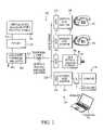
- FIG. 2is a block diagram of one exemplary embodiment of the gateway system of the present invention.
- FIG. 3is a block diagram and partial schematic of one embodiment of the line power converter unit (LPCU) according to the invention.
- LPCUline power converter unit
- FIG. 4is a block diagram and partial schematic of one embodiment of the DSL gateway unit according to the invention.
- FIG. 5is a block diagram including partial schematic of one embodiment of the jack adapter module according to the invention.
- FIG. 5 ais a perspective view of an exemplary embodiment of the jack adapter module of FIG. 5 .
- FIG. 5 bis a block diagram including partial schematic illustrating a first (standard telephone) operating mode of the adapter module of FIG. 5 .
- FIG. 5 cis a block diagram including partial schematic illustrating a second (HPN bypass) operating mode of the adapter module of FIG. 5 .
- FIG. 5 dis a block diagram including partial schematic illustrating a third (digital multi-line line powered telephone or equivalent) operating mode of the adapter module of FIG. 5 .
- FIG. 5 eis a block diagram including partial schematic illustrating a first low-cost alternate embodiment (adapted for a standard telephone) of the adapter module of FIG. 5 .
- FIG. 5 fis a block diagram including partial schematic illustrating a second low-cost alternate embodiment (adapted for HPN bypass) of the adapter module of FIG. 5 .
- FIG. 5 gis a block diagram including partial schematic illustrating a third low-cost alternate embodiment (adapted for a digital telephone) of the adapter module of FIG. 5 .
- FIG. 6is a logical flow diagram illustrating one embodiment of the method of installing the system of FIG. 2 .
- signal conditioningshall be understood to include, but not be limited to, signal voltage transformation, filtering and noise mitigation or elimination, current limiting, sampling, signal processing, and time delay.
- integrated circuitshall include any type of integrated device of any function, whether single or multiple die, or small or large scale of integration, including without limitation applications specific integrated circuits (ASICs), field programmable gate arrays (FPGAs), digital processors (e.g., DSPs, CISC microprocessors, or RISC processors), and so-called “system-on-a-chip” (SoC) devices.
- ASICsapplications specific integrated circuits
- FPGAsfield programmable gate arrays
- DSPsdigital signal processors
- CISC microprocessorsCISC microprocessors
- RISCRISC processors
- homeplugas used herein is meant specifically to include devices and systems compliant with the HomePlugTM Powerline Alliance Version 1.0 Specification for powerline-based home networks, and generally to include all other comparable devices adapted for powerline networking.
- the ADSL unit of the present inventionis married with (i) a power recovery circuit, (ii) a home phone network (HPN) interface module device (using for example the existing house or building wiring), and (iii) a home power plug interface module, all coupled to the same Telco line.
- HPNhome phone network
- HPNhome phone network
- a home power plug interface moduleall coupled to the same Telco line.
- This combination of componentsis referred to generally herein as the gateway module, described in further detail below.
- a wireless interfaces module(such as those compliant with IEEE Std.
- 802.11B or the “Bluetooth” 2.4 GHz wireless interface standardis also optionally provided to facilitate wireless data interchange between the system and a remote or mobile device such as a laptop computer, personal digital assistant (PDA), cellular or cordless telephone, and the like.
- a remote or mobile devicesuch as a laptop computer, personal digital assistant (PDA), cellular or cordless telephone, and the like.
- the line powered gateway module of the present inventioncan be advantageously installed by the subscriber by simply locating a power plug (e.g., 115 VAC, 60 Hz single-phase outlet) in physical proximity to a telephone jack (e.g., RJ-type modular jack), and plugging the gateway module into the power plug, with a cord running to the closest telephone jack.
- a power pluge.g., 115 VAC, 60 Hz single-phase outlet
- a telephone jacke.g., RJ-type modular jack
- the present inventionutilizes one or more specially configured adapter modules which are plugged into respective phone jacks at the installation premises, and which receive extension devices (e.g., telephones) via an extension port on the adapter modules.
- the aforementioned adapter moduleadvantageously extracts its power from the wall jack as the ADSL unit does, and provides power to both an associated HPN unit (e.g., integrated circuit specifically adapted for home phone network applications) and low voltage subscriber's line interface circuit (SLIC) for a standard type telephone.
- HPN unite.g., integrated circuit specifically adapted for home phone network applications
- SLICsubscriber's line interface circuit
- the adapter module(s)also is/are configured to provide an automatic jack sensor circuit that automatically senses the type or configuration of the device attached to the new derived port (e.g., a regular phone, an HPN device, or a new multi-line digital phone), and applies the correct interface for the sensed device.
- the adapter moduleis self-configuring, thereby providing for ease of installation and use, especially when switching between various types of subscriber extension devices.
- HPN signals on the existing house or building telephone wiring, the RF signals associated with the air interface, and the signals present on the homeplug (or other suitable power line technologies) running through the structureallows ready data connection and interchange in any physical location within the structure (and potentially outside the structure, consistent with the limitations of the air interface).
- Any computer, notebook, PDA, or other data capable devicecan easily be connected around the structure via either HPN or wireless interface.
- printers or other computer peripheralscan also be connected and shared by all computers or other networked devices using the HPN circuitry by simply plugging into one of the installed telephone jacks present in the structure.
- miscellaneous devicescan be connected to the gateway module (and thus made available for all computers/devices on the network) via the house power wiring using devices equipped with homeplug or comparable interfaces.
- Any homeplug equipped devicessuch as video cameras, alarm devices, coffee makers, refrigerators, intercoms, etc. are automatically connected the gateway module of the present invention by plugging the device into the wall power receptacle.
- the entire house or structure(or even series of structures) can be rapidly and easily interconnected via a simple self-installation by the user with no additional wiring, cables, etc.
- the systemgenerally comprises a digital subscriber line access multiplexer (DSLAM) 202 , a line power converter unit (LPCU) 204 , a gateway module 206 , and one or more adapter modules 208 , 210 , 212 .
- DSLAMdigital subscriber line access multiplexer
- LPCUline power converter unit
- gateway module 206a gateway module 206 , and one or more adapter modules 208 , 210 , 212 .
- the system 200is connected via Telco line 214 from the DSLAM 202 to the Internet Service Provider (ISP) and/or indirectly to a central office (CO) telecommunications switch 220 (or other dial tone source) of the type well understood in the telecommunications art.
- COcentral office
- a direct current (DC) power supply 222such as from one or more conventional batteries, is provided for the LPCU 204 , which in the illustrated embodiment provides a minus 48 VDC to the LPCU for use therein as described in greater detail with respect to FIG. 3 , although other values may be substituted.
- the LPCU 204is accordingly connected to the wiring within the designated installation site 226 (e.g., home, small business, etc.) via a conventional installed analog telephone line 214 .
- An interposed signal repeater/amplifier 216is also optionally provided within the telephone line 224 to enhance signal quality over longer distances or particularly noisy pathways if required.
- Such repeaters and amplifiersare well understood in the telecommunications arts, and accordingly are discussed further herein.
- the installed telecommunications wiring 228 within the site 226is used as the basis for interconnection and communication between the various components 206 , 208 , 210 , 212 of the system 200 .
- the gateway module 206is connected to the telecommunications wiring 228 via a first modular jack 230 (here, the RJ-type, yet others may be readily substituted), while the one or more adapter modules 208 , 210 , 212 are interfaced with the wiring 228 via other respective jacks 232 , 236 , 238 located throughout the site 226 .
- the extension devices 240 , 242 , 244are accordingly plugged into respective adapter modules 208 , 210 , 212 as described in greater detail below, thereby providing signal continuity between the ISP or Telco switch 220 and the various extension devices 240 , 242 , 244 .
- the gateway module 206is also plugged into a nearby wall power outlet, such as the 115 VAC, 60 Hz single phase variety of the type in widespread use today. It will be recognized, however, that other types of power sources may be used either in the alternative or in conjunction with the foregoing, including for example 220 VAC, 50 Hz, single phase.
- the gateway module 206advantageously extracts power from the telecommunications wiring 228 , as do the various adapter modules 208 , 210 , 212 via their own respective power extraction circuits.
- the DSLAM 202 of the illustrated embodimentdiffers from the standard prior art DSLAM in that the DSL of the present DSLAM 202 is also adapted to utilize the desirable 200 Hz–25 KHz bands for longer range (or faster data rates), plus the new or derived phone lines. Specifically, the DSLAM 202 of the illustrated embodiment utilizes a high-pass filter tuned to start at 200 Hz versus 25 KHz, as well as additional software.
- the LPCU 204 of the embodiment of FIG. 2replaces the splitters typically found in prior art configurations in the central office, and converts the ⁇ 48V input power signal 222 to a higher voltage (up to +/ ⁇ 135 V) to provide the gateway module 206 with up to 12 Watts of power.
- the LPCU 204 in the illustrated embodimentcomprises a current source of approximately 60–100 mA, and is partially under control of the gateway module's power extractor unit 406 (see discussion of FIG. 4 ) in order to adjust for the desired power at the gateway module(s) 206 .
- FIG. 3shows the internal details of the LPCU 204 of the system 200 of FIG. 2 .
- the DSLAM signalspass through the low frequency splitter/combiner capacitors 302 to the subscriber's line.
- the power feed currentpasses through the feed inductors 304 to the subscriber's line 308 .
- the inductance values of the feed inductors 304 of the present embodimentare selected to achieve a resonance condition for the best hi-pass/low-pass response at 200 Hz, although it will be appreciated that other frequencies and/or inductor selection criterion may be substituted if desired.
- a component of the total inductanceis provided by the DC/DC converter circuit 320 , so as to minimize the inductors cost and size, thereby allowing the LPCU 204 to be smaller and less costly to manufacture.
- the ground fault detection circuitry 310 of the LPCU 204senses any ground-based current, and trips the converter output in the feed circuit when a fault is detected (such as from a ground occurring when someone touches the line 308 ).
- the LPCU 204is advantageously adapted to be flexible in supplying both minimum power for short loops and providing elevated voltage and power for the longer loops (and long loops with mid-span line powered repeaters or amplifiers).
- the control circuitrysends a signal to the LPCU to increase the power provided.
- the DC/DC converter 320 included within the LPCU 204also regulates the positive voltage applied to the subscriber's line 308 to minimize the corrosion rate of the copper used within that line.
- the polarity of the line powercan optionally be reversed periodically to minimize the corrosion rate.
- the gateway module 206includes all of the technologies needed to network the site 226 .
- the gateway 206includes a line power extractor block (LPEB) 406 which regulates the tip/ring (T/R) line voltage to approximately 72V in the illustrated embodiment (or alternatively some other voltage adapted for long range applications), and extracts power for the DSL module 430 , HPN module 440 , and wireless interface 450 and homeplug circuitry 460 if so equipped.
- the gateway module 206may also communicate with the LPCU 204 to adjust the magnitude of the power provided thereby as required for various loop lengths and number of jack adapters 208 , 210 , 212 .
- the gateway module 206further includes a controller 422 that manages all the states, features, and data flow of the system.
- the controller 422is physically part of the DSL modem chip (described below), although it will be recognized that discrete components or circuits may be used in place of the integrated circuits if desired.
- the DSL module 430 of the gateway module 206comprises a conventional DSL modulator/demodulator apparatus of the type well know in the telecommunication arts, which is further adapted to use the added 200 Hz–25 khz bandwidth previously described provided by the system configuration to generate multiple telephone dial tone circuits, while not taking bandwidth away from the original DSL modem channel.
- the DSL module 430 of the illustrated embodimentcomprises an integrated circuit chipset (such as the Wildwire® ADSL modem chipsets manufactured by Lucent Technologies or the Alcatel DynaMiTeTM DSL chipset, although other chipsets may be used).
- the use of such IC chipsetsaffords the advantages of low cost and space savings, as well as integrating the aforementioned control features associated with the controller 422 .
- the gateway module 206further comprises an HPN module 440 of the type well understood in the networking arts, which interfaces with the DSL module 430 in order to couple data from the DSL to the home network over the installed telephone lines 228 .
- This arrangementallows the generated or “derived” phone lines to be routed over the telephone wiring 228 to any phone jack at the site 226 .
- a wireless module 450which communicates to any remote module within or proximate to the site 226 (or for that matter with physically remote devices via a local interface) using the antenna in the gateway's wireless module 450 , such as in a notebook computer or video monitor.
- Any number of different wireless transmission methodologiesmay be employed to transfer data between these entities including, inter alia, point to point transmission via the Infrared Data Association's (“IrDA”) infrared based wireless transmission standard; wireless radio frequency (“RF”) based local area network (“LAN”) connections based on the IEEE 802.11A or 802.11B LAN access standards, or the Home RF Shared Wireless Access Protocol.
- IrDAInfrared Data Association's
- RFwireless radio frequency
- LANlocal area network
- the construction and operation of each of these air interfacesis well known in the communications arts, and accordingly are not described further herein.
- a “Bluetooth” wireless interface(or alternatively, other so-called “3G” (third generation) communications technology) is utilized for transferring data between the gateway module 206 and mobile or remote devices, and/or between the PC extension device and its peripherals/accessories.
- the wireless module 450 of the gateway 206comprises a transceiver and modulator device (not shown) used in the form of an SoC integrated circuit.
- the Bluetooth topologysupports both point-to-point and point-to-multipoint connections. Multiple “slave” devices can be set to communicate with a “master” device.
- the gateway module 206 of the present inventionwhen outfitted with a Bluetooth or comparable wireless suite, may communicate directly with other Bluetooth compliant mobile or fixed devices including the subject's cellular telephone, PDA, notebook computer, or desktop computer.
- Bluetooth-compliant devicesoperate in the 2.4 GHz ISM band.
- the ISM bandis dedicated to unlicensed users, including medical facilities, thereby advantageously allowing for unrestricted spectral access in home or small office environments of the type in which the present invention is especially useful.
- the modulator of the SoC device previously describeduses one or more variants of frequency shift keying, such as Gaussian Frequency Shift Keying (GFSK) or Gaussian Minimum Shift keying (GMSK) of the type well known in the art to modulate data onto the carrier(s), although other types of modulation (such as phase modulation or amplitude modulation) may be used.
- frequency shift keyingsuch as Gaussian Frequency Shift Keying (GFSK) or Gaussian Minimum Shift keying (GMSK) of the type well known in the art to modulate data onto the carrier(s), although other types of modulation (such as phase modulation or amplitude modulation) may be used.
- GFSKGaussian Frequency Shift Keying
- GMSKGaussian Minimum Shift keying
- Spectral access of the devicecan be accomplished via frequency divided multiple access (FDMA), although other types of access such as frequency hopping spread spectrum (FHSS), direct sequence spread spectrum (DSSS, including code division multiple access) using a pseudo-noise spreading code, or even time division multiple access may be used depending on the needs of the particular application and site 226 .
- FDMAfrequency divided multiple access
- FHSSfrequency hopping spread spectrum
- DSSSdirect sequence spread spectrum
- pseudo-noise spreading codeor even time division multiple access may be used depending on the needs of the particular application and site 226 .
- An exemplary SoCis the SiW1502 Radio Modem IC manufactured by Silicon Wave Corporation of San Diego, Calif., a low-power consumption device with integrated RF logic and Bluetooth protocol stack adapted for Bluetooth applications.
- the deviceis a fully integrated 2.4 GHz radio transceiver with a GFSK modem contained on a single chip.
- the SiW1502 chipis offered as a stand alone IC or, may be obtained with the Silicon Wave Odyssey SiW1601 Link Controller IC.
- the SiW1502 form factoris 7.0 ⁇ 7.0 ⁇ 1.0 mm package which is readily disposed within the interior volume of the gateway module 206 described herein.
- the gateway module 206 of the inventionfurther comprises a homeplug (or other power line carrier technology) interface module 460 .
- the output 464 of the homeplug module 460is coupled via, e.g., a standard 115 VAC, 60 Hz, single phase grounded electrical cord 464 to the power lines within in the site 226 (not shown) by simply plugging the gateway module 206 into a wall power outlet.
- This homeplug interface 460 and connection to the site wiringallows any equipment or device (e.g., appliances, home entertainment systems, HVAC control systems, etc.) to communicate with the gateway module directly without the need for additional wiring or air interfaces.
- the adapter modules 208 , 210 , 212 of FIG. 2provide self-install capability of the line power gateway of the present invention. These adapter modules are now described in detail with respect to FIG. 5 .
- each adapter moduleis semi-permanently attached or “lockable” so as to prevent plugging any standard telephones or similar devices into the existing telephone wiring jacks 230 , 232 , 236 , 238 , which is necessary to prevent overloading the DC line power voltage present at the phone jacks.
- the adapter modules 208 , 210 , 212 of the present inventionare plugged into the telephone jacks, and extract power from the telephone line 228 via a power extractor module 504 which is electrically coupled to the wall jack and a SLIC module 530 .
- the adapter modulesuse this extracted power to provide power to an internal HPN circuit 510 within the respective modules, an/or to an HPN circuit 520 in a digital phone which is in turn plugged into the jack 524 of the module.
- the internal module HPN circuit 510 of each moduleextracts a derived phone line from the HPN module 440 in the gateway module 206 ( FIG. 4 ), and drives the SLIC module 530 within each respective adapter module 208 , 210 , 212 to generate tip and ring lead signals to drive the module's phone jack 524 .
- FIG. 5 aillustrates one exemplary embodiment of the physical configuration of the adapter modules.
- the module 208 , 210 , 212comprises a housing element 570 having a modular plug 572 with associated locking tab 574 , and at least one modular jack 524 disposed on the upper surface 578 of the housing element 570 .
- a second jack 529may also be provided for any variety of different purposes, such as additional extension devices, RJ- 11 interface, etc.
- the housing element 570 and modular plug 572are configured such that the tab 574 is rendered inaccessible by the subscriber when the adapter is installed, thereby frustrating inadvertent or unintentional removal. It will be recognized, however, that while an obscured plug/tab arrangement is used in the illustrated embodiment, other methods of frustrating adapter module removal by the subscriber may also be employed, including for example the use of one or more fasteners (e.g., nut/bolt, screw, snap, or rivet) which mate the housing element 570 to the wall jack, adhesives, or even magnetic coupling between complementary magnets disposed in the housing element 570 and wall jack.
- the wall jackmay actually be manufactured to include the adapter module circuitry as an integral component, such that the subscriber replaces the existing wall jack with the combined wall jack and adapter unit.
- the functions provided by the adapter modules 208 , 210 , 212 of the present inventionneed not necessarily be lockable or semi-permanent in nature; non-lockable modules may be used with equal success.
- the use of locking modulesacts effectively as a safety device for the subscriber, to help frustrate inadvertent removal of the module(s) and subsequent insertion of a modular plug from a telephone or similar device into the wall jack.
- the extension port jack 524 of the adapter module and its supporting circuitryis also adapted to automatically sense and adjust the function of the jack for a standard phone (SLIC output), a HPN Broad Band interface (HPN only output), or a new line powered digital phone (HPN output and a power feed). This sensing and adjustment is accomplished in the illustrated embodiment as described below.
- SLIC outputstandard phone
- HPN Broad Band interfaceHPN only output
- HPN output and a power feeda new line powered digital phone
- the jack adapter modulesenses the type of device plugged into the adapter module jack 524 .
- devicesThere are generally three types of devices that may be used: (i) regular telephone equipment such as standard telephones (either wired or with cordless base station), answering machines, fax machines, caller ID devices, or analog modems; (ii) standard HPN (1.0 or 2.0) devices that are AC coupled and include any HPN to PC interface modules, or printer or other peripherals that have an HPN input; or (iii) a new line powered single or multi-line HPN telephone (or other desired low-power function), such devices using DC power as well as communicating via HPN signals.
- regular telephone equipmentsuch as standard telephones (either wired or with cordless base station), answering machines, fax machines, caller ID devices, or analog modems
- standard HPN (1.0 or 2.0) devicesthat are AC coupled and include any HPN to PC interface modules, or printer or other peripherals that have an HPN input
- the typical automatic sensing and adapter module configurationstarts with the SLIC always feeding a DC battery voltage of approximately 10 VDC on T/R.
- the SLIC 530 and HPN circuit 510 of the adapter modulelooks for an HPN signal from the extension device, and if none is present, will determine that the device is a conventional phone or similar device. If the extension device is conventional, the adapter module communicates to the HPN circuitry (e.g., chip) to request dial tone through the gateway to the serving CO. Once the requested dial tone signal is detected from the CO, the SLIC 530 generates dial tone for the local phone which can then dial the desired number. When the off hook condition appears, the HPN signals are blocked by a relay K 1 and associated switches 544 , which forms a splitter 550 within the module.
- the HPN circuitrye.g., chip
- the HPN circuitrywill sense the HPN signal from the device, and bypass the HPN signal around the adapter module circuitry as shown in FIG. 5 c herein.
- the SLIC loop current sensorwill sense DC current flow and the adapter module HPN circuitry will detect an HPN request which will then bypass the HPN phone signal to the gateway module 206 , and switch the SLIC 530 to the power feed mode to power the phone, as illustrated in FIG. 5 d herein.
- the power extractor module 504obtains power from the line (wall jack), powers the HPN circuitry 510 of the module 206 to obtain a phone circuit with send/receive transmission, and provides signaling (on/off hook and ringing).
- the HPN 510drives the low power SLIC module 530 , which generates the 10 VDC battery feed voltage for the telephone, as well as generating the ringing voltage to ring the phone. This configuration is illustrated in FIG. 5 a .
- the adapter modulefurther includes means for setting or selecting the line (of the multiple derived lines) to connect to the adapter's phone jack.
- this meanscomprises a multi-position selector switch, although other configurations (e.g., automatic selection based on parametric sampling, algorithmic control, etc.) may be used as well. Since each HPN circuit has a unique address, the line selection may be selected at the gateway upon installation as well.
- the line HPN signalis simply bypassed from the installed line 228 (wall jack) to the adapter phone jack 524 via a bypass circuit 540 and in-line capacitors 542 as shown in FIG. 5 b.
- the HPN signalis bypassed to the digital phone jack 524 , and the feed or SLIC circuit 530 switches modes and feeds power to the digital phone. Since the digital phone can be a multi-line phone, it is equivalent to a key system. This is ideal for example in a small office, where multiple lines with multiple phones are used. Other lower cost digital phones or devices can be set to the desired derived phone line such as, for example, in a teenager's room or other home application.
- FIG. 5 eillustrates one exemplary embodiment of such a low-cost adapter module 594 , configured for use with a standard telephone (first operating mode described above).
- the configuration of this module 594is generally similar to that of the module 208 of FIG. 5 , with the exception that the contacts 542 and bypass pathway 540 are removed since the need for such components is obviated.
- FIG. 5 fillustrates a second embodiment of the “low-cost” adapter module 596 adapted for use in the “HPN only” mode previously described.
- the adapter modulesimply comprises a current path 540 with contacts 542 disposed between the extension device jack 524 and the wall jack.
- FIG. 5 gillustrates a third embodiment of the low-cost adapter module, configured for use with digital telephones as discussed above.
- the adapter module 598comprises a power extractor 504 , power circuit 597 , bypass pathway 540 with contacts 542 , and splitter arrangement.
- the HPN circuitry 510 of the embodiment of FIG. 5is removed in that it is not required, and the SLIC 530 of FIG. 5 is replaced with a simplified power supply circuit which supplies power directly to the extension device as shown in FIG. 5 g.
- FIG. 6the method of installing the aforementioned system 200 and associated components is described in detail. It is noted that while the following description is cast in terms of the system of FIG. 2 as installed in a typical residential structure, the broader method of the invention is equally applicable to other configurations and types of sites.
- the method 600generally comprises first determining scope and location of telecommunications wiring and any HPN systems within the site 226 , including the number of wall jacks present therein (step 602 ).
- the gateway module 206is positioned in a location having access to both a telecommunications wiring jack and a power supply jack (e.g., wall plug) per step 604 .
- the gateway module's phone line portis connected (via appropriate cabling) to the telephone jack, and the module's power plug 464 is connected to the local power supply jack.
- the gateway moduleis, in one embodiment, sized such that it's weight and bulk is mechanically supported by the power plug when the module is plugged into the latter.
- adapter modules 208 , 210 , 212are then positioned at respective ones of each of the remaining telephone jacks throughout the site 226 , the adapter modules being plugged into the wall jacks such that they lock into place (if so equipped) as previously described. It is noted that not every telecommunications line wall jack must be outfitted with an adapter module 208 , 210 , 212 ; however, those not so equipped should not have a standard telephone or other device installed, since the potential for DC line voltage overload exists as previously described.
- step 608the various extension devices (i.e., standard telephones, HPN gateways, digital multi-line phones, etc) are plugged into the jacks 524 of their respective adapter modules 208 , 210 , 212 .
- the flexibility inherent with the present inventionis underscored here, since any of the foregoing devices can be indiscriminately plugged into the adapter module jack 524 of any adapter module without any particular configuration restrictions or additional wiring requirements (other than setting the line selection means associated with the applicable adapter module when a standard phone is plugged into the jack 524 to permit selection between multiple derived lines).
- step 610the system 200 is tested to ensure proper functionality.
- testingcan be optionally built into the system (e.g. a self-test algorithm and supporting hardware adapted to run and provide the subscriber test results upon system installation and/or startup), or performed by external test equipment as is well understood in the telecommunications art.
- Self-testperformed automatically by the system when installed, with simple instructions to the user, is optimal, since it reduces the installation burden on the subscriber.
- Parameters to be testedmay include, for example, the data rate across the Telco line/DSL module, proper line voltage regulation under normal and loss-of-power conditions by the LPCU 204 , proper communication between the gateway module controller unit 422 and the LPCU 204 , etc.
Landscapes
- Engineering & Computer Science (AREA)
- Signal Processing (AREA)
- Power Engineering (AREA)
- Computer Networks & Wireless Communication (AREA)
- Telephonic Communication Services (AREA)
- Cable Transmission Systems, Equalization Of Radio And Reduction Of Echo (AREA)
Abstract
Description
Claims (39)
Priority Applications (3)
| Application Number | Priority Date | Filing Date | Title |
|---|---|---|---|
| US09/975,142US7003102B2 (en) | 2001-10-10 | 2001-10-10 | Telecommunications gateway and method |
| TW091123222ATW589839B (en) | 2001-10-10 | 2002-10-08 | Telecommunications gateway and method |
| PCT/US2002/032290WO2003041369A1 (en) | 2001-10-10 | 2002-10-09 | Telecommunications gateway and method |
Applications Claiming Priority (1)
| Application Number | Priority Date | Filing Date | Title |
|---|---|---|---|
| US09/975,142US7003102B2 (en) | 2001-10-10 | 2001-10-10 | Telecommunications gateway and method |
Publications (2)
| Publication Number | Publication Date |
|---|---|
| US20030068033A1 US20030068033A1 (en) | 2003-04-10 |
| US7003102B2true US7003102B2 (en) | 2006-02-21 |
Family
ID=25522735
Family Applications (1)
| Application Number | Title | Priority Date | Filing Date |
|---|---|---|---|
| US09/975,142Expired - Fee RelatedUS7003102B2 (en) | 2001-10-10 | 2001-10-10 | Telecommunications gateway and method |
Country Status (3)
| Country | Link |
|---|---|
| US (1) | US7003102B2 (en) |
| TW (1) | TW589839B (en) |
| WO (1) | WO2003041369A1 (en) |
Cited By (34)
| Publication number | Priority date | Publication date | Assignee | Title |
|---|---|---|---|---|
| US20040125819A1 (en)* | 2001-07-05 | 2004-07-01 | Yehuda Binder | Telephone outlet with packet telephony adapter, and a network using same |
| US20040170193A1 (en)* | 2003-02-28 | 2004-09-02 | Schauer Steven A. | Large transmissions on packetized data bus |
| US20050010954A1 (en)* | 2003-07-09 | 2005-01-13 | Serconet Ltd. | Modular outlet |
| US20050025162A1 (en)* | 2002-11-13 | 2005-02-03 | Yehuda Binder | Addressable outlet, and a network using same |
| US20050100043A1 (en)* | 2000-04-19 | 2005-05-12 | Serconet Ltd | Network combining wired and non-wired segments |
| US20050117603A1 (en)* | 2000-04-18 | 2005-06-02 | Serconet, Ltd. | Telephone communication system over a single telephone line |
| US20050117723A1 (en)* | 2002-03-13 | 2005-06-02 | Enrique Romero Lopez | System for adapting a data and voice transmission local network to an analog telephone line |
| US20050180561A1 (en)* | 2004-02-16 | 2005-08-18 | Serconet Ltd. | Outlet add-on module |
| US20050249245A1 (en)* | 2004-05-06 | 2005-11-10 | Serconet Ltd. | System and method for carrying a wireless based signal over wiring |
| US20060003816A1 (en)* | 2004-06-30 | 2006-01-05 | Takeshi Yamashita | Telephone terminal and method for supplying power to the same |
| US20060018339A1 (en)* | 1998-07-28 | 2006-01-26 | Serconet, Ltd | Local area network of serial intelligent cells |
| US20060072741A1 (en)* | 2003-01-30 | 2006-04-06 | Serconet Ltd | Method and system for providing DC power on local telephone lines |
| US20060098638A1 (en)* | 2001-10-11 | 2006-05-11 | Serconet Ltd. | Outlet with analog signal adapter, a method for use thereof and a network using said outlet |
| US20060133588A1 (en)* | 2000-03-20 | 2006-06-22 | Serconet Ltd. | Telephone outlet for implementing a local area network over telephone lines and a local area network using such outlets |
| US20060197428A1 (en)* | 2005-02-21 | 2006-09-07 | Takeshi Tonegawa | Electron devices with non-evaporation-type getters and method for manufacturing the same |
| US20070014290A1 (en)* | 2005-07-12 | 2007-01-18 | Cisco Technology, Inc. | Address resolution mechanism for ethernet maintenance endpoints |
| US20070076595A1 (en)* | 2005-09-30 | 2007-04-05 | Samsung Electronics Co., Ltd. | Power line communication method and apparatus |
| US20070086444A1 (en)* | 2003-03-13 | 2007-04-19 | Serconet Ltd. | Telephone system having multiple distinct sources and accessories therefor |
| US20070124418A1 (en)* | 2004-01-13 | 2007-05-31 | Yehuda Binder | Information device |
| US20070173202A1 (en)* | 2006-01-11 | 2007-07-26 | Serconet Ltd. | Apparatus and method for frequency shifting of a wireless signal and systems using frequency shifting |
| US20080030971A1 (en)* | 2006-08-01 | 2008-02-07 | Tyco Electronics Corporation | Wall-Mounted Network Outlet |
| US20080292073A1 (en)* | 1999-07-20 | 2008-11-27 | Serconet, Ltd | Network for telephony and data communication |
| US20090167099A1 (en)* | 2007-12-28 | 2009-07-02 | Chung-Ta Chin | Switch Device for Switching Different Type Signals |
| US20100039242A1 (en)* | 2006-11-09 | 2010-02-18 | Main.Net Communications Ltd. | Apparatus and method for data communication over power lines |
| US7826408B1 (en) | 2005-03-14 | 2010-11-02 | Ozmo, Inc. | Apparatus and method for integrating short-range wireless personal area networks for a wireless local area network infrastructure |
| US7873058B2 (en) | 2004-11-08 | 2011-01-18 | Mosaid Technologies Incorporated | Outlet with analog signal adapter, a method for use thereof and a network using said outlet |
| US8175649B2 (en) | 2008-06-20 | 2012-05-08 | Corning Mobileaccess Ltd | Method and system for real time control of an active antenna over a distributed antenna system |
| US8582598B2 (en) | 1999-07-07 | 2013-11-12 | Mosaid Technologies Incorporated | Local area network for distributing data communication, sensing and control signals |
| US8594133B2 (en) | 2007-10-22 | 2013-11-26 | Corning Mobileaccess Ltd. | Communication system using low bandwidth wires |
| US8897215B2 (en) | 2009-02-08 | 2014-11-25 | Corning Optical Communications Wireless Ltd | Communication system using cables carrying ethernet signals |
| US9184960B1 (en) | 2014-09-25 | 2015-11-10 | Corning Optical Communications Wireless Ltd | Frequency shifting a communications signal(s) in a multi-frequency distributed antenna system (DAS) to avoid or reduce frequency interference |
| US9338823B2 (en) | 2012-03-23 | 2016-05-10 | Corning Optical Communications Wireless Ltd | Radio-frequency integrated circuit (RFIC) chip(s) for providing distributed antenna system functionalities, and related components, systems, and methods |
| US20170366923A1 (en)* | 2016-06-16 | 2017-12-21 | I/O Interconnect, Ltd. | Method for making a host personal computer act as an accessory in bluetooth piconet |
| US10165612B2 (en)* | 2016-06-16 | 2018-12-25 | I/O Interconnected, Ltd. | Wireless connecting method, computer, and non-transitory computer-readable storage medium |
Families Citing this family (32)
| Publication number | Priority date | Publication date | Assignee | Title |
|---|---|---|---|---|
| EP1316170A2 (en)* | 2000-06-07 | 2003-06-04 | Conexant Systems, Inc. | Method and apparatus for medium access control in powerline communication network systems |
| US6868117B1 (en)* | 2001-02-26 | 2005-03-15 | Apple Computer, Inc. | Splitter and microfilter dongle for a single RJ11 DSL/analog combo modem |
| US20030212802A1 (en)* | 2002-05-09 | 2003-11-13 | Gateway, Inc. | Proximity network encryption and setup |
| KR100859408B1 (en)* | 2002-09-28 | 2008-09-22 | 주식회사 케이티 | Digital subscriber network terminal and digital subscriber network access device for home auto communication |
| US6998964B2 (en)* | 2003-05-30 | 2006-02-14 | Adc Dsl Systems, Inc. | Splitter |
| US7583703B2 (en)* | 2003-10-23 | 2009-09-01 | Cisco Technology Inc. | System and method for power injection and out of band communications on shared medium |
| US20060018328A1 (en)* | 2004-07-23 | 2006-01-26 | Comcast Cable Holdings, Llc | Method and system for powerline networking |
| RU2007117902A (en)* | 2004-10-15 | 2008-11-20 | Юниверссел Корпорейшн (Us) | SYSTEM AND METHOD OF COMMUNICATION USING ADAPTERS OF A WIRED COMMUNICATION LINK |
| US20060188266A1 (en)* | 2004-12-28 | 2006-08-24 | Optical Solutions, Inc. | Optical network terminal with wide input range power converter |
| US9596031B2 (en)* | 2005-03-01 | 2017-03-14 | Alexander Ivan Soto | System and method for a subscriber-powered network element |
| US7856032B2 (en)* | 2005-04-04 | 2010-12-21 | Current Technologies, Llc | Multi-function modem device |
| US20060255930A1 (en)* | 2005-05-12 | 2006-11-16 | Berkman William H | Power line communications system and method |
| US7672448B2 (en)* | 2005-06-23 | 2010-03-02 | 2Wire, Inc. | Network interface device with a remote power source |
| EP1764992A1 (en)* | 2005-09-16 | 2007-03-21 | Hon Hai Precision Industry Co., Ltd. | Network device for receiving ADSL and HPNA signals |
| US7589536B2 (en)* | 2007-01-05 | 2009-09-15 | Apple Inc. | Systems and methods for determining the configuration of electronic connections |
| KR100648263B1 (en)* | 2005-11-29 | 2006-11-23 | 엘에스전선 주식회사 | Power line communication system and communication equipment used in the power line communication system |
| US7923855B2 (en) | 2006-02-17 | 2011-04-12 | Calix, Inc. | Communication between network interface device and subscriber devices via power supply lines |
| US8520835B2 (en)* | 2006-04-18 | 2013-08-27 | 2Wire, Inc. | Method and apparatus for providing power to a network interface device via telephone lines |
| US7965977B2 (en)* | 2006-04-18 | 2011-06-21 | 2Wire, Inc. | Remote antenna system |
| US8588402B2 (en)* | 2007-10-26 | 2013-11-19 | Stephen H. Gould | Method and system for providing power and data over a voice grade/pots infrastructure for use in communicating with and/or controlling multiple remote network and non-network devices |
| FR2926942A1 (en)* | 2008-01-24 | 2009-07-31 | Herve Michel Eric Breton | Unified network access point for communicating and transmitting data via e.g. telephony cable of building, has Ethernet interface realizing multi-medium unified Ethernet access point, and microcontroller managing functionalities of point |
| GB0910741D0 (en)* | 2009-06-22 | 2009-08-05 | Tangotec Ltd | Ethernet adapter |
| SG185731A1 (en) | 2010-05-28 | 2013-01-30 | Apple Inc | Dual orientation connector with external contacts |
| US20130022132A1 (en)* | 2011-07-21 | 2013-01-24 | Calix, Inc. | Communication among network devices at subscriber premises |
| US9293876B2 (en) | 2011-11-07 | 2016-03-22 | Apple Inc. | Techniques for configuring contacts of a connector |
| US8799527B2 (en) | 2012-09-07 | 2014-08-05 | Apple Inc. | Data structures for facilitating communication between a host device and an accessory |
| US8724281B2 (en) | 2012-04-25 | 2014-05-13 | Apple Inc. | Techniques for detecting removal of a connector |
| US8891216B2 (en) | 2012-04-25 | 2014-11-18 | Apple Inc. | Techniques for detecting removal of a connector |
| CN102710824A (en)* | 2012-05-30 | 2012-10-03 | 洪珍 | Fax machine adapter special for mobile phone |
| US9307312B2 (en) | 2013-03-15 | 2016-04-05 | Apple Inc. | Audio accessory with internal clock |
| EP2835934B1 (en)* | 2013-08-07 | 2021-04-07 | Alcatel Lucent | Reverse powered remote node and method for reverse powering a remote node |
| EP4047911A1 (en)* | 2021-02-23 | 2022-08-24 | Deutsche Telekom AG | Plug-in module for a tae, method for its identification and reader |
Citations (1)
| Publication number | Priority date | Publication date | Assignee | Title |
|---|---|---|---|---|
| US6658108B1 (en)* | 1999-04-09 | 2003-12-02 | Premisenet Incorporated | System and method for distributing power over a premises network |
Family Cites Families (13)
| Publication number | Priority date | Publication date | Assignee | Title |
|---|---|---|---|---|
| GB2071461B (en)* | 1980-02-14 | 1984-01-25 | Standard Telephones Cables Ltd | Telephone line feed |
| US4578533A (en)* | 1980-11-03 | 1986-03-25 | Universal Data Systems, Inc. | Switchable line powered modem |
| US5237606A (en)* | 1991-05-01 | 1993-08-17 | Charles Industries, Ltd. | Enhanced synchronous rectifier |
| US5504811A (en)* | 1994-12-29 | 1996-04-02 | Wilcom, Inc. | Enhanced line powered amplifier |
| US6047016A (en)* | 1997-06-23 | 2000-04-04 | Cellnet Data Systems, Inc. | Processing a spread spectrum signal in a frequency adjustable system |
| US6212274B1 (en)* | 1997-06-26 | 2001-04-03 | Data Race, Inc. | Line powered modem |
| US6104791A (en)* | 1998-06-11 | 2000-08-15 | Conexant Systems, Inc. | System and method for performing telephone line-in-use detection, extension pick-up detection, and remote hang-up detection in a modem |
| US6252957B1 (en)* | 1998-10-07 | 2001-06-26 | Teledex Corporation | Low power line selection circuit for a telephone |
| US6212259B1 (en)* | 1998-11-19 | 2001-04-03 | Excelsus Technologies, Inc. | Impedance blocking filter circuit |
| US6298037B1 (en)* | 1998-12-14 | 2001-10-02 | Analog Devices, Inc. | Network data filtering |
| CA2390945A1 (en)* | 1999-11-15 | 2001-05-25 | Amos R. Mansfield | Highly reliable power line communications system |
| WO2001084806A2 (en)* | 2000-05-02 | 2001-11-08 | Phonex Broadband Corporation | Method and system for adapting a telephone line modem for use on the power line |
| US6404393B1 (en)* | 2000-10-04 | 2002-06-11 | 3Com Corporation | Embedded antenna in a type II PCMCIA card |
- 2001
- 2001-10-10USUS09/975,142patent/US7003102B2/ennot_activeExpired - Fee Related
- 2002
- 2002-10-08TWTW091123222Apatent/TW589839B/ennot_activeIP Right Cessation
- 2002-10-09WOPCT/US2002/032290patent/WO2003041369A1/ennot_activeApplication Discontinuation
Patent Citations (1)
| Publication number | Priority date | Publication date | Assignee | Title |
|---|---|---|---|---|
| US6658108B1 (en)* | 1999-04-09 | 2003-12-02 | Premisenet Incorporated | System and method for distributing power over a premises network |
Cited By (174)
| Publication number | Priority date | Publication date | Assignee | Title |
|---|---|---|---|---|
| US8885660B2 (en) | 1998-07-28 | 2014-11-11 | Conversant Intellectual Property Management Incorporated | Local area network of serial intelligent cells |
| US8270430B2 (en) | 1998-07-28 | 2012-09-18 | Mosaid Technologies Incorporated | Local area network of serial intelligent cells |
| US7830858B2 (en) | 1998-07-28 | 2010-11-09 | Mosaid Technologies Incorporated | Local area network of serial intelligent cells |
| US7852874B2 (en) | 1998-07-28 | 2010-12-14 | Mosaid Technologies Incorporated | Local area network of serial intelligent cells |
| US7965735B2 (en) | 1998-07-28 | 2011-06-21 | Mosaid Technologies Incorporated | Local area network of serial intelligent cells |
| US7969917B2 (en) | 1998-07-28 | 2011-06-28 | Mosaid Technologies Incorporated | Local area network of serial intelligent cells |
| US7978726B2 (en) | 1998-07-28 | 2011-07-12 | Mosaid Technologies Incorporated | Local area network of serial intelligent cells |
| US7986708B2 (en) | 1998-07-28 | 2011-07-26 | Mosaid Technologies Incorporated | Local area network of serial intelligent cells |
| US7424031B2 (en) | 1998-07-28 | 2008-09-09 | Serconet, Ltd. | Local area network of serial intelligent cells |
| US8908673B2 (en) | 1998-07-28 | 2014-12-09 | Conversant Intellectual Property Management Incorporated | Local area network of serial intelligent cells |
| US7653015B2 (en) | 1998-07-28 | 2010-01-26 | Mosaid Technologies Incorporated | Local area network of serial intelligent cells |
| US8325636B2 (en) | 1998-07-28 | 2012-12-04 | Mosaid Technologies Incorporated | Local area network of serial intelligent cells |
| US20060291497A1 (en)* | 1998-07-28 | 2006-12-28 | Israeli Company Of Serconet Ltd. | Local area network of serial intelligent cells |
| US8867523B2 (en) | 1998-07-28 | 2014-10-21 | Conversant Intellectual Property Management Incorporated | Local area network of serial intelligent cells |
| US8885659B2 (en) | 1998-07-28 | 2014-11-11 | Conversant Intellectual Property Management Incorporated | Local area network of serial intelligent cells |
| US20060018339A1 (en)* | 1998-07-28 | 2006-01-26 | Serconet, Ltd | Local area network of serial intelligent cells |
| US20060018338A1 (en)* | 1998-07-28 | 2006-01-26 | Serconet, Ltd. | Local area network of serial intelligent cells |
| US20060062241A1 (en)* | 1998-07-28 | 2006-03-23 | Serconet, Ltd | Local area network of serial intelligent cells |
| US7221679B2 (en) | 1998-07-28 | 2007-05-22 | Serconet Ltd. | Local area network of serial intelligent cells |
| US7187695B2 (en) | 1998-07-28 | 2007-03-06 | Serconet Ltd. | Local area network of serial intelligent cells |
| US8582598B2 (en) | 1999-07-07 | 2013-11-12 | Mosaid Technologies Incorporated | Local area network for distributing data communication, sensing and control signals |
| US7492875B2 (en) | 1999-07-20 | 2009-02-17 | Serconet, Ltd. | Network for telephony and data communication |
| US7522713B2 (en) | 1999-07-20 | 2009-04-21 | Serconet, Ltd. | Network for telephony and data communication |
| US8351582B2 (en) | 1999-07-20 | 2013-01-08 | Mosaid Technologies Incorporated | Network for telephony and data communication |
| US8929523B2 (en) | 1999-07-20 | 2015-01-06 | Conversant Intellectual Property Management Inc. | Network for telephony and data communication |
| US20080292073A1 (en)* | 1999-07-20 | 2008-11-27 | Serconet, Ltd | Network for telephony and data communication |
| US7483524B2 (en) | 1999-07-20 | 2009-01-27 | Serconet, Ltd | Network for telephony and data communication |
| US8855277B2 (en) | 2000-03-20 | 2014-10-07 | Conversant Intellectual Property Managment Incorporated | Telephone outlet for implementing a local area network over telephone lines and a local area network using such outlets |
| US20060133588A1 (en)* | 2000-03-20 | 2006-06-22 | Serconet Ltd. | Telephone outlet for implementing a local area network over telephone lines and a local area network using such outlets |
| US7715534B2 (en) | 2000-03-20 | 2010-05-11 | Mosaid Technologies Incorporated | Telephone outlet for implementing a local area network over telephone lines and a local area network using such outlets |
| US7522714B2 (en) | 2000-03-20 | 2009-04-21 | Serconet Ltd. | Telephone outlet for implementing a local area network over telephone lines and a local area network using such outlets |
| US8363797B2 (en) | 2000-03-20 | 2013-01-29 | Mosaid Technologies Incorporated | Telephone outlet for implementing a local area network over telephone lines and a local area network using such outlets |
| US7397791B2 (en) | 2000-04-18 | 2008-07-08 | Serconet, Ltd. | Telephone communication system over a single telephone line |
| US7466722B2 (en) | 2000-04-18 | 2008-12-16 | Serconet Ltd | Telephone communication system over a single telephone line |
| US20060182095A1 (en)* | 2000-04-18 | 2006-08-17 | Serconet Ltd. | Telephone communication system over a single telephone line |
| US8559422B2 (en) | 2000-04-18 | 2013-10-15 | Mosaid Technologies Incorporated | Telephone communication system over a single telephone line |
| US20060182094A1 (en)* | 2000-04-18 | 2006-08-17 | Serconet Ltd. | Telephone communication system over a single telephone line |
| US7593394B2 (en) | 2000-04-18 | 2009-09-22 | Mosaid Technologies Incorporated | Telephone communication system over a single telephone line |
| US7197028B2 (en) | 2000-04-18 | 2007-03-27 | Serconet Ltd. | Telephone communication system over a single telephone line |
| US20050117603A1 (en)* | 2000-04-18 | 2005-06-02 | Serconet, Ltd. | Telephone communication system over a single telephone line |
| US8000349B2 (en) | 2000-04-18 | 2011-08-16 | Mosaid Technologies Incorporated | Telephone communication system over a single telephone line |
| US8223800B2 (en) | 2000-04-18 | 2012-07-17 | Mosaid Technologies Incorporated | Telephone communication system over a single telephone line |
| US20080043646A1 (en)* | 2000-04-18 | 2008-02-21 | Serconet Ltd. | Telephone communication system over a single telephone line |
| US20050100043A1 (en)* | 2000-04-19 | 2005-05-12 | Serconet Ltd | Network combining wired and non-wired segments |
| US7933297B2 (en) | 2000-04-19 | 2011-04-26 | Mosaid Technologies Incorporated | Network combining wired and non-wired segments |
| US20050254516A1 (en)* | 2000-04-19 | 2005-11-17 | Serconet, Ltd. | Network combining wired and non-wired segments |
| US8873586B2 (en) | 2000-04-19 | 2014-10-28 | Conversant Intellectual Property Management Incorporated | Network combining wired and non-wired segments |
| US8289991B2 (en) | 2000-04-19 | 2012-10-16 | Mosaid Technologies Incorporated | Network combining wired and non-wired segments |
| US20100135191A1 (en)* | 2000-04-19 | 2010-06-03 | Mosaid Technologies Incorporated | Network Combining Wired and Non-Wired Segments |
| US20050259691A1 (en)* | 2000-04-19 | 2005-11-24 | Serconet Ltd | Network combining wired and non-wired segments |
| US8982904B2 (en) | 2000-04-19 | 2015-03-17 | Conversant Intellectual Property Management Inc. | Network combining wired and non-wired segments |
| US7636373B2 (en) | 2000-04-19 | 2009-12-22 | Mosaid Technologies Incorporated | Network combining wired and non-wired segments |
| US8982903B2 (en) | 2000-04-19 | 2015-03-17 | Conversant Intellectual Property Management Inc. | Network combining wired and non-wired segments |
| US7633966B2 (en) | 2000-04-19 | 2009-12-15 | Mosaid Technologies Incorporated | Network combining wired and non-wired segments |
| US20050277328A1 (en)* | 2000-04-19 | 2005-12-15 | Serconet Ltd | Network combining wired and non-wired segments |
| US8873575B2 (en) | 2000-04-19 | 2014-10-28 | Conversant Intellectual Property Management Incorporated | Network combining wired and non-wired segments |
| US8867506B2 (en) | 2000-04-19 | 2014-10-21 | Conversant Intellectual Property Management Incorporated | Network combining wired and non-wired segments |
| US7715441B2 (en) | 2000-04-19 | 2010-05-11 | Mosaid Technologies Incorporated | Network combining wired and non-wired segments |
| US7876767B2 (en) | 2000-04-19 | 2011-01-25 | Mosaid Technologies Incorporated | Network combining wired and non-wired segments |
| US8848725B2 (en) | 2000-04-19 | 2014-09-30 | Conversant Intellectual Property Management Incorporated | Network combining wired and non-wired segments |
| US20050063403A1 (en)* | 2001-07-05 | 2005-03-24 | Serconet Ltd. | Telephone outlet with packet telephony adaptor, and a network using same |
| US20050083959A1 (en)* | 2001-07-05 | 2005-04-21 | Serconet, Ltd. | Telephone outlet with packet telephony adapter, and a network using same |
| US7542554B2 (en) | 2001-07-05 | 2009-06-02 | Serconet, Ltd | Telephone outlet with packet telephony adapter, and a network using same |
| US7680255B2 (en) | 2001-07-05 | 2010-03-16 | Mosaid Technologies Incorporated | Telephone outlet with packet telephony adaptor, and a network using same |
| US20040125819A1 (en)* | 2001-07-05 | 2004-07-01 | Yehuda Binder | Telephone outlet with packet telephony adapter, and a network using same |
| US7769030B2 (en) | 2001-07-05 | 2010-08-03 | Mosaid Technologies Incorporated | Telephone outlet with packet telephony adapter, and a network using same |
| US8761186B2 (en) | 2001-07-05 | 2014-06-24 | Conversant Intellectual Property Management Incorporated | Telephone outlet with packet telephony adapter, and a network using same |
| US8472593B2 (en) | 2001-07-05 | 2013-06-25 | Mosaid Technologies Incorporated | Telephone outlet with packet telephony adaptor, and a network using same |
| US7889720B2 (en) | 2001-10-11 | 2011-02-15 | Mosaid Technologies Incorporated | Outlet with analog signal adapter, a method for use thereof and a network using said outlet |
| US7453895B2 (en) | 2001-10-11 | 2008-11-18 | Serconet Ltd | Outlet with analog signal adapter, a method for use thereof and a network using said outlet |
| US7860084B2 (en) | 2001-10-11 | 2010-12-28 | Mosaid Technologies Incorporated | Outlet with analog signal adapter, a method for use thereof and a network using said outlet |
| US7436842B2 (en) | 2001-10-11 | 2008-10-14 | Serconet Ltd. | Outlet with analog signal adapter, a method for use thereof and a network using said outlet |
| US20060098638A1 (en)* | 2001-10-11 | 2006-05-11 | Serconet Ltd. | Outlet with analog signal adapter, a method for use thereof and a network using said outlet |
| US7953071B2 (en) | 2001-10-11 | 2011-05-31 | Mosaid Technologies Incorporated | Outlet with analog signal adapter, a method for use thereof and a network using said outlet |
| US20080134263A1 (en)* | 2001-10-11 | 2008-06-05 | Serconet Ltd. | Outlet with analog signal adapter, a method for use thereof and a network using said outlet |
| US20110096778A1 (en)* | 2001-10-11 | 2011-04-28 | Mosaid Technologies Incorporated | Outlet with analog signal adapter, a method for use thereof and a network using said outlet |
| US7212616B2 (en)* | 2002-03-13 | 2007-05-01 | Enrique Romero Lopez | System for adapting a conventional telephone line to a data and voice transmission local network |
| US20050117723A1 (en)* | 2002-03-13 | 2005-06-02 | Enrique Romero Lopez | System for adapting a data and voice transmission local network to an analog telephone line |
| US8295185B2 (en) | 2002-11-13 | 2012-10-23 | Mosaid Technologies Inc. | Addressable outlet for use in wired local area network |
| US20080198777A1 (en)* | 2002-11-13 | 2008-08-21 | Serconet Ltd. | Addressable outlet, and a network using the same |
| US7911992B2 (en) | 2002-11-13 | 2011-03-22 | Mosaid Technologies Incorporated | Addressable outlet, and a network using the same |
| US20050025162A1 (en)* | 2002-11-13 | 2005-02-03 | Yehuda Binder | Addressable outlet, and a network using same |
| US7522615B2 (en) | 2002-11-13 | 2009-04-21 | Serconet, Ltd. | Addressable outlet, and a network using same |
| US7990908B2 (en) | 2002-11-13 | 2011-08-02 | Mosaid Technologies Incorporated | Addressable outlet, and a network using the same |
| US20060072741A1 (en)* | 2003-01-30 | 2006-04-06 | Serconet Ltd | Method and system for providing DC power on local telephone lines |
| US8107618B2 (en)* | 2003-01-30 | 2012-01-31 | Mosaid Technologies Incorporated | Method and system for providing DC power on local telephone lines |
| US20060233354A1 (en)* | 2003-01-30 | 2006-10-19 | Serconet Ltd | Method and system for providing DC power on local telephone Lines |
| US7317793B2 (en) | 2003-01-30 | 2008-01-08 | Serconet Ltd | Method and system for providing DC power on local telephone lines |
| US8787562B2 (en) | 2003-01-30 | 2014-07-22 | Conversant Intellectual Property Management Inc. | Method and system for providing DC power on local telephone lines |
| US7702095B2 (en) | 2003-01-30 | 2010-04-20 | Mosaid Technologies Incorporated | Method and system for providing DC power on local telephone lines |
| US20070127715A1 (en)* | 2003-01-30 | 2007-06-07 | Serconet Ltd | Method and system for providing DC power on local telephone lines |
| US20040170193A1 (en)* | 2003-02-28 | 2004-09-02 | Schauer Steven A. | Large transmissions on packetized data bus |
| US7609725B2 (en)* | 2003-02-28 | 2009-10-27 | Lsi Corporation | Large transmissions on packetized data bus |
| US20070086444A1 (en)* | 2003-03-13 | 2007-04-19 | Serconet Ltd. | Telephone system having multiple distinct sources and accessories therefor |
| US20070147433A1 (en)* | 2003-03-13 | 2007-06-28 | Serconet Ltd. | Telephone system having multiple distinct sources and accessories therefor |
| US20070153836A1 (en)* | 2003-03-13 | 2007-07-05 | Serconet, Ltd. | Telephone system having multiple distinct sources and accessories therefor |
| US7656904B2 (en) | 2003-03-13 | 2010-02-02 | Mosaid Technologies Incorporated | Telephone system having multiple distinct sources and accessories therefor |
| US8238328B2 (en) | 2003-03-13 | 2012-08-07 | Mosaid Technologies Incorporated | Telephone system having multiple distinct sources and accessories therefor |
| US7738453B2 (en) | 2003-03-13 | 2010-06-15 | Mosaid Technologies Incorporated | Telephone system having multiple sources and accessories therefor |
| US7867035B2 (en) | 2003-07-09 | 2011-01-11 | Mosaid Technologies Incorporated | Modular outlet |
| US7873062B2 (en) | 2003-07-09 | 2011-01-18 | Mosaid Technologies Incorporated | Modular outlet |
| US20070019669A1 (en)* | 2003-07-09 | 2007-01-25 | Serconet Ltd. | Modular outlet |
| US7688841B2 (en) | 2003-07-09 | 2010-03-30 | Mosaid Technologies Incorporated | Modular outlet |
| US20050010954A1 (en)* | 2003-07-09 | 2005-01-13 | Serconet Ltd. | Modular outlet |
| US8235755B2 (en) | 2003-09-07 | 2012-08-07 | Mosaid Technologies Incorporated | Modular outlet |
| US8092258B2 (en) | 2003-09-07 | 2012-01-10 | Mosaid Technologies Incorporated | Modular outlet |
| US20110097939A1 (en)* | 2003-09-07 | 2011-04-28 | Mosaid Technologies Incorporated | Modular outlet |
| US7686653B2 (en) | 2003-09-07 | 2010-03-30 | Mosaid Technologies Incorporated | Modular outlet |
| US8591264B2 (en) | 2003-09-07 | 2013-11-26 | Mosaid Technologies Incorporated | Modular outlet |
| US8360810B2 (en) | 2003-09-07 | 2013-01-29 | Mosaid Technologies Incorporated | Modular outlet |
| US7690949B2 (en) | 2003-09-07 | 2010-04-06 | Mosaid Technologies Incorporated | Modular outlet |
| US20100115564A1 (en)* | 2004-01-13 | 2010-05-06 | Yehuda Binder | Information device |
| US20110013759A1 (en)* | 2004-01-13 | 2011-01-20 | May Patents Ltd. | Information device |
| US11095708B2 (en) | 2004-01-13 | 2021-08-17 | May Patents Ltd. | Information device |
| US11032353B2 (en) | 2004-01-13 | 2021-06-08 | May Patents Ltd. | Information device |
| US10986164B2 (en) | 2004-01-13 | 2021-04-20 | May Patents Ltd. | Information device |
| US10986165B2 (en) | 2004-01-13 | 2021-04-20 | May Patents Ltd. | Information device |
| US20100115571A1 (en)* | 2004-01-13 | 2010-05-06 | Yehuda Binder | Information device |
| US20090147934A1 (en)* | 2004-01-13 | 2009-06-11 | Yehuda Binder | Information device |
| US20110013758A1 (en)* | 2004-01-13 | 2011-01-20 | May Patents Ltd. | Information device |
| US20090132679A1 (en)* | 2004-01-13 | 2009-05-21 | Serconet, Ltd. | Information device |
| US20070124418A1 (en)* | 2004-01-13 | 2007-05-31 | Yehuda Binder | Information device |
| US20110009077A1 (en)* | 2004-01-13 | 2011-01-13 | May Patents Ltd. | Information device |
| US20090198795A1 (en)* | 2004-01-13 | 2009-08-06 | Yehuda Binder | Information device |
| US8611528B2 (en)* | 2004-02-16 | 2013-12-17 | Mosaid Technologies Incorporated | Outlet add-on module |
| US20050180561A1 (en)* | 2004-02-16 | 2005-08-18 | Serconet Ltd. | Outlet add-on module |
| US20080227333A1 (en)* | 2004-02-16 | 2008-09-18 | Serconet Ltd. | Outlet add-on module |
| US20080231111A1 (en)* | 2004-02-16 | 2008-09-25 | Serconet Ltd. | Outlet add-on module |
| US7756268B2 (en)* | 2004-02-16 | 2010-07-13 | Mosaid Technologies Incorporated | Outlet add-on module |
| US20070275595A1 (en)* | 2004-02-16 | 2007-11-29 | Serconet Ltd. | Outlet add-on module |
| US20080226060A1 (en)* | 2004-02-16 | 2008-09-18 | Serconet Ltd. | Outlet add-on module |
| US8565417B2 (en)* | 2004-02-16 | 2013-10-22 | Mosaid Technologies Incorporated | Outlet add-on module |
| US7881462B2 (en)* | 2004-02-16 | 2011-02-01 | Mosaid Technologies Incorporated | Outlet add-on module |
| US8542819B2 (en)* | 2004-02-16 | 2013-09-24 | Mosaid Technologies Incorporated | Outlet add-on module |
| US8243918B2 (en)* | 2004-02-16 | 2012-08-14 | Mosaid Technologies Incorporated | Outlet add-on module |
| US20080219430A1 (en)* | 2004-02-16 | 2008-09-11 | Serconet Ltd. | Outlet add-on module |
| US8325759B2 (en)* | 2004-05-06 | 2012-12-04 | Corning Mobileaccess Ltd | System and method for carrying a wireless based signal over wiring |
| US20050249245A1 (en)* | 2004-05-06 | 2005-11-10 | Serconet Ltd. | System and method for carrying a wireless based signal over wiring |
| US8325693B2 (en) | 2004-05-06 | 2012-12-04 | Corning Mobileaccess Ltd | System and method for carrying a wireless based signal over wiring |
| US20080280569A1 (en)* | 2004-05-06 | 2008-11-13 | Serconet Ltd. | System and Method for Carrying a Wireless Based Signal Over Wiring |
| US7634079B2 (en)* | 2004-06-30 | 2009-12-15 | Kabushiki Kaisha Toshiba | Telephone terminal and method for supplying power to the same |
| US20060003816A1 (en)* | 2004-06-30 | 2006-01-05 | Takeshi Yamashita | Telephone terminal and method for supplying power to the same |
| US7873058B2 (en) | 2004-11-08 | 2011-01-18 | Mosaid Technologies Incorporated | Outlet with analog signal adapter, a method for use thereof and a network using said outlet |
| US20060197428A1 (en)* | 2005-02-21 | 2006-09-07 | Takeshi Tonegawa | Electron devices with non-evaporation-type getters and method for manufacturing the same |
| US9264991B1 (en) | 2005-03-14 | 2016-02-16 | Omega Sub Holdings, Inc. | Apparatus and method for integrating short-range wireless personal area networks for a wireless local area network infrastructure |
| US7826408B1 (en) | 2005-03-14 | 2010-11-02 | Ozmo, Inc. | Apparatus and method for integrating short-range wireless personal area networks for a wireless local area network infrastructure |
| US8599814B1 (en) | 2005-03-14 | 2013-12-03 | Omega Sub Holdings, Inc. | Apparatus and method for integrating short-range wireless personal area networks for a wireless local area network infrastructure |
| US8165102B1 (en) | 2005-03-14 | 2012-04-24 | Ozmo, Inc. | Apparatus and method for integrating short-range wireless personal area networks for a wireless local area network infrastructure |
| US7889754B2 (en)* | 2005-07-12 | 2011-02-15 | Cisco Technology, Inc. | Address resolution mechanism for ethernet maintenance endpoints |
| US20070014290A1 (en)* | 2005-07-12 | 2007-01-18 | Cisco Technology, Inc. | Address resolution mechanism for ethernet maintenance endpoints |
| US20070076595A1 (en)* | 2005-09-30 | 2007-04-05 | Samsung Electronics Co., Ltd. | Power line communication method and apparatus |
| US8169923B2 (en)* | 2005-09-30 | 2012-05-01 | Samsung Electronics Co., Ltd. | Power line communication method and apparatus |
| US7587001B2 (en) | 2006-01-11 | 2009-09-08 | Serconet Ltd. | Apparatus and method for frequency shifting of a wireless signal and systems using frequency shifting |
| US20070173202A1 (en)* | 2006-01-11 | 2007-07-26 | Serconet Ltd. | Apparatus and method for frequency shifting of a wireless signal and systems using frequency shifting |
| US7813451B2 (en) | 2006-01-11 | 2010-10-12 | Mobileaccess Networks Ltd. | Apparatus and method for frequency shifting of a wireless signal and systems using frequency shifting |
| US8184681B2 (en) | 2006-01-11 | 2012-05-22 | Corning Mobileaccess Ltd | Apparatus and method for frequency shifting of a wireless signal and systems using frequency shifting |
| US7612653B2 (en) | 2006-08-01 | 2009-11-03 | Tyco Electronics Corporation | Wall-mounted network outlet |
| US20080030971A1 (en)* | 2006-08-01 | 2008-02-07 | Tyco Electronics Corporation | Wall-Mounted Network Outlet |
| US8149106B2 (en)* | 2006-11-09 | 2012-04-03 | Main.Net Communications Ltd. | Apparatus and method for data communication over power lines |
| US20100039242A1 (en)* | 2006-11-09 | 2010-02-18 | Main.Net Communications Ltd. | Apparatus and method for data communication over power lines |
| US9813229B2 (en) | 2007-10-22 | 2017-11-07 | Corning Optical Communications Wireless Ltd | Communication system using low bandwidth wires |
| US8594133B2 (en) | 2007-10-22 | 2013-11-26 | Corning Mobileaccess Ltd. | Communication system using low bandwidth wires |
| US9549301B2 (en) | 2007-12-17 | 2017-01-17 | Corning Optical Communications Wireless Ltd | Method and system for real time control of an active antenna over a distributed antenna system |
| US20090167099A1 (en)* | 2007-12-28 | 2009-07-02 | Chung-Ta Chin | Switch Device for Switching Different Type Signals |
| US8175649B2 (en) | 2008-06-20 | 2012-05-08 | Corning Mobileaccess Ltd | Method and system for real time control of an active antenna over a distributed antenna system |
| US8897215B2 (en) | 2009-02-08 | 2014-11-25 | Corning Optical Communications Wireless Ltd | Communication system using cables carrying ethernet signals |
| US9338823B2 (en) | 2012-03-23 | 2016-05-10 | Corning Optical Communications Wireless Ltd | Radio-frequency integrated circuit (RFIC) chip(s) for providing distributed antenna system functionalities, and related components, systems, and methods |
| US9948329B2 (en) | 2012-03-23 | 2018-04-17 | Corning Optical Communications Wireless, LTD | Radio-frequency integrated circuit (RFIC) chip(s) for providing distributed antenna system functionalities, and related components, systems, and methods |
| US9184960B1 (en) | 2014-09-25 | 2015-11-10 | Corning Optical Communications Wireless Ltd | Frequency shifting a communications signal(s) in a multi-frequency distributed antenna system (DAS) to avoid or reduce frequency interference |
| US9515855B2 (en) | 2014-09-25 | 2016-12-06 | Corning Optical Communications Wireless Ltd | Frequency shifting a communications signal(s) in a multi-frequency distributed antenna system (DAS) to avoid or reduce frequency interference |
| US9253003B1 (en) | 2014-09-25 | 2016-02-02 | Corning Optical Communications Wireless Ltd | Frequency shifting a communications signal(S) in a multi-frequency distributed antenna system (DAS) to avoid or reduce frequency interference |
| US10165612B2 (en)* | 2016-06-16 | 2018-12-25 | I/O Interconnected, Ltd. | Wireless connecting method, computer, and non-transitory computer-readable storage medium |
| US9906893B2 (en)* | 2016-06-16 | 2018-02-27 | I/O Interconnect, Ltd. | Method for making a host personal computer act as an accessory in bluetooth piconet |
| US20170366923A1 (en)* | 2016-06-16 | 2017-12-21 | I/O Interconnect, Ltd. | Method for making a host personal computer act as an accessory in bluetooth piconet |
Also Published As
| Publication number | Publication date |
|---|---|
| WO2003041369A1 (en) | 2003-05-15 |
| WO2003041369A8 (en) | 2004-05-06 |
| TW589839B (en) | 2004-06-01 |
| US20030068033A1 (en) | 2003-04-10 |
Similar Documents
| Publication | Publication Date | Title |
|---|---|---|
| US7003102B2 (en) | Telecommunications gateway and method | |
| US8107618B2 (en) | Method and system for providing DC power on local telephone lines | |
| US8594115B2 (en) | Distributing voice and data information over wireless and wireline networks | |
| EP1302023B1 (en) | System and method for providing power over a home phone line network | |
| US6535983B1 (en) | System and method for signaling and detecting request for power over ethernet | |
| US6107912A (en) | Wireless modem jack | |
| US7526034B2 (en) | Method and apparatus for communicating between devices having no common electrical ground | |
| US4703499A (en) | Distributed privacy oriented telephone extension system | |
| US6658108B1 (en) | System and method for distributing power over a premises network | |
| US8520835B2 (en) | Method and apparatus for providing power to a network interface device via telephone lines | |
| JP5360964B2 (en) | A device that provides telephone service to telephones that are plugged into private telephone wiring that is not connected to a central office telephone exchange | |
| JPH07505029A (en) | Hybrid fiber in loop telephone system | |
| KR20010102721A (en) | Ring signal and direct current generating device for telephone line when wireless connection |
Legal Events
| Date | Code | Title | Description |
|---|---|---|---|
| AS | Assignment | Owner name:EXCELSUS TECHNOLOGIES, INC., CALIFORNIA Free format text:ASSIGNMENT OF ASSIGNORS INTEREST;ASSIGNOR:KIKO, FREDERICK J.;REEL/FRAME:012814/0426 Effective date:20020327 | |
| AS | Assignment | Owner name:PULSE ENGINEERING, INC., CALIFORNIA Free format text:MERGER;ASSIGNOR:EXCELSUS TECHNOLOGIES, INC.;REEL/FRAME:015156/0919 Effective date:20040622 Owner name:PULSE ENGINEERING, INC.,CALIFORNIA Free format text:MERGER;ASSIGNOR:EXCELSUS TECHNOLOGIES, INC.;REEL/FRAME:015156/0919 Effective date:20040622 | |
| AS | Assignment | Owner name:JPMORGAN CHASE BANK, N.A., AS ADMINISTRATIVE AGENT Free format text:SECURITY AGREEMENT;ASSIGNOR:PULSE ENGINEERING, INC.;REEL/FRAME:022343/0821 Effective date:20090304 | |
| FPAY | Fee payment | Year of fee payment:4 | |
| AS | Assignment | Owner name:PULSE ELECTRONICS, INC., CALIFORNIA Free format text:CHANGE OF NAME;ASSIGNOR:PULSE ENGINEERING, INC.;REEL/FRAME:025689/0448 Effective date:20101029 | |
| AS | Assignment | Owner name:PULSE ELECTRONICS, INC., CALIFORNIA Free format text:CHANGE OF NAME;ASSIGNOR:PULSE ENGINEERING, INC.;REEL/FRAME:026661/0234 Effective date:20101028 | |
| REMI | Maintenance fee reminder mailed | ||
| AS | Assignment | Owner name:CANTOR FITZGERALD SECURITIES, NEW YORK Free format text:NOTICE OF SUBSTITUTION OF ADMINISTRATIVE AGENT IN TRADEMARKS AND PATENTS;ASSIGNOR:JPMORGAN CHASE BANK, N.A.;REEL/FRAME:031898/0476 Effective date:20131030 | |
| LAPS | Lapse for failure to pay maintenance fees | ||
| STCH | Information on status: patent discontinuation | Free format text:PATENT EXPIRED DUE TO NONPAYMENT OF MAINTENANCE FEES UNDER 37 CFR 1.362 | |
| FP | Lapsed due to failure to pay maintenance fee | Effective date:20140221 |