US7002333B2 - Process and device for compensating the low frequency magnetic field in an inductive signal coupling unit - Google Patents
Process and device for compensating the low frequency magnetic field in an inductive signal coupling unitDownload PDFInfo
- Publication number
- US7002333B2 US7002333B2US11/010,535US1053504AUS7002333B2US 7002333 B2US7002333 B2US 7002333B2US 1053504 AUS1053504 AUS 1053504AUS 7002333 B2US7002333 B2US 7002333B2
- Authority
- US
- United States
- Prior art keywords
- coupling unit
- current
- magnetic field
- compensating
- low frequency
- Prior art date
- Legal status (The legal status is an assumption and is not a legal conclusion. Google has not performed a legal analysis and makes no representation as to the accuracy of the status listed.)
- Expired - Lifetime
Links
- 230000005291magnetic effectEffects0.000titleclaimsabstractdescription64
- 230000008878couplingEffects0.000titleclaimsabstractdescription49
- 238000010168coupling processMethods0.000titleclaimsabstractdescription49
- 238000005859coupling reactionMethods0.000titleclaimsabstractdescription49
- 230000001939inductive effectEffects0.000titleclaimsabstractdescription29
- 238000000034methodMethods0.000titleclaimsabstractdescription12
- 230000008569processEffects0.000titleclaimsabstractdescription10
- 230000005294ferromagnetic effectEffects0.000claimsabstractdescription38
- 239000004020conductorSubstances0.000claimsabstractdescription35
- 238000002347injectionMethods0.000claimsabstractdescription16
- 239000007924injectionSubstances0.000claimsabstractdescription16
- 230000005611electricityEffects0.000claimsabstractdescription10
- 238000004804windingMethods0.000claimsdescription33
- 230000004907fluxEffects0.000claimsdescription9
- 230000000694effectsEffects0.000claimsdescription4
- 230000035699permeabilityEffects0.000claimsdescription4
- 238000001514detection methodMethods0.000abstractdescription11
- 238000003780insertionMethods0.000abstractdescription8
- 230000037431insertionEffects0.000abstractdescription8
- 230000005540biological transmissionEffects0.000abstractdescription4
- 238000004891communicationMethods0.000abstractdescription3
- 229920006395saturated elastomerPolymers0.000description4
- 230000008901benefitEffects0.000description3
- 230000006698inductionEffects0.000description2
- 239000000243solutionSubstances0.000description2
- 230000005355Hall effectEffects0.000description1
- 230000009471actionEffects0.000description1
- 230000003247decreasing effectEffects0.000description1
- 238000005259measurementMethods0.000description1
- 230000009467reductionEffects0.000description1
- 229910000859α-FeInorganic materials0.000description1
Images


Classifications
- G—PHYSICS
- G01—MEASURING; TESTING
- G01R—MEASURING ELECTRIC VARIABLES; MEASURING MAGNETIC VARIABLES
- G01R15/00—Details of measuring arrangements of the types provided for in groups G01R17/00 - G01R29/00, G01R33/00 - G01R33/26 or G01R35/00
- G01R15/14—Adaptations providing voltage or current isolation, e.g. for high-voltage or high-current networks
- G01R15/18—Adaptations providing voltage or current isolation, e.g. for high-voltage or high-current networks using inductive devices, e.g. transformers
- G01R15/183—Adaptations providing voltage or current isolation, e.g. for high-voltage or high-current networks using inductive devices, e.g. transformers using transformers with a magnetic core
- G01R15/185—Adaptations providing voltage or current isolation, e.g. for high-voltage or high-current networks using inductive devices, e.g. transformers using transformers with a magnetic core with compensation or feedback windings or interacting coils, e.g. 0-flux sensors
Definitions
- the present inventionrelates to a process and a device that allow to compensate the low frequency magnetic field which is produced in an inductive coupling unit.
- the inventionis preferably applicable for injecting high frequency signals on the electricity grid by means of an inductive coupling unit, and its object is to minimize the insertion loss of a high frequency signal on the electricity grid, to which end it avoids the effect of magnetic saturation which occurs in the inductive coupling unit.
- the way of carrying out the injectiondepends mainly on the transmission medium employed.
- inductive coupling unitswhich are usually constituted by current transformers which are placed around the power conductors in which it is desired to induce the signal.
- the operationis based on the principle that currents which vary in time generate magnetic fields which vary in time and viceversa.
- the radiofrequency (RF) current it is desired to injectproduces a variable magnetic field (in time, and therefore a magnetic flux also variable in time) inside the ferromagnetic core of the coupling unit and, besides, the variation of magnetic flux around a conductor, induces therein a current proportional to this variation.
- An inductor to which this method can be appliedcomprises a main coil, a magnetic core, a control coil means to detect the presence in this main coil of current at a frequency below a determined limit, and means to apply a control circuit to said control coil, which tends to compensate the flux produced by the detected current.
- the present inventionallows the inductive coupling to be carried out without saturation of the ferromagnetic core taking place and without additional insertion loss occurring.
- the invention as claimedcomprises a process for compensating the low frequency magnetic field in an inductive signal coupling unit, wherein the coupling unit comprises a magnetic core which surrounds a conductor through which a low frequency current is circulating in order to inject a high frequency signal therein.
- the process of the inventionis characterised in that it foresees a selective detection of the current which is circulating through the conductor or of the magnetic field produced in the coupling unit, in order to obtain thereafter a compensating current based on the value obtained in the detection performed, said injection current being produced with an external source, by the actual equipment which wishes to transmit the high frequency signal over the grid or automatically by induction on a winding around the coupler. Subsequently the injection of the compensating current obtained in the coupling unit is produced through a low pass filter which offers a high impedance to the high frequency signal it is desired to inject.
- the action of injecting the compensating currentresults in that, in the inductive coupling unit, a magnetic field is produced equal and opposite to that produced by the current which is circulating through the conductor, whereby saturation is avoided in the magnetic core of the inductive coupling unit without adding insertion loss for the desired signal it is to transmit, and maximum efficiency is obtained.
- the inventionhas been specially conceived to send high frequency signals over the electricity grid in which a low frequency current is circulating.
- the detection of the magnetic fieldis carried out in the ferromagnetic core of the inductive signal coupling unit.
- the magnetic field detectedis compared with a reference signal in order to obtain the compensating current, so that the signal of the measure of the magnetic field is maintained practically equal to the reference signal, wherein said reference signal lies between 0 and a value such that the coupling unit is prevented from becoming saturated, that is, the signal inside the ferromagnetic core of the coupling unit never surpasses the maximum flux density it is capable of withstanding.
- the detectionis achieved by measuring the current which is circulating in the electricity grid.
- the injection of the compensating current obtainedis carried out by means of a compensation winding which is applied on the ferromagnetic core of the inductive signal coupling unit through a low pass filter which offers a high impedance for the high frequency signals it is desired to inject.
- the measurement of the current which is circulating through the conductoris carried out by means of a winding arranged on a ferromagnetic core which is independent of the inductive signal coupling unit.
- the inventionalso foresees that the detection, the obtaining of the compensating current, and the injection of said current are carried out simultaneously by locating a winding with a single winding around a double core which forms the ferromagnetic core of the coupling unit.
- the inventionalso refers to a low frequency magnetic field compensating device in an inductive signal coupling unit which works according to the aforementioned process.
- the device of the inventioncomprises a detector which is selectively constituted by a current detector which is circulating through the conductor or by a detector of the magnetic field produced in the coupling unit.
- the device of the inventioncomprises a control module by means of which a compensating current is calculated and produced, based on the value obtained in the detector.
- the current produced by the control moduleis injected in the conductor by means of a compensation winding arranged on the ferromagnetic core of the coupling unit, and through a filter offering high impedance to high frequencies which prevents the high frequency signal to be injected from being affected by the injection of the compensating current.
- the injection of the compensating currentproduces a magnetic field in the ferromagnetic core, equal and opposite to that produced by the current which is circulating through the conductor, so that saturation is avoided of the magnetic core of the inductive coupling unit, whereby insertion loss is not added and the maximum efficiency is obtained in the transmission of the signals over the electricity grid.
- the detectoris constituted by means of a device for measuring the magnetic field inside the ferromagnetic core of the coupling unit.
- the signal provided by the detectoris compared with a reference signal, which preferably is zero, and is applied to the control module so that the latter generates the compensating current to obtain a signal from the detector equal to the reference signal.
- the injection of the current produced by the control moduleis carried out through a low pass filter and by means of a compensation winding which is arranged around the ferromagnetic core of the inductive signal coupling unit.
- the device of the inventionalso foresees that it comprises a single winding around a double core which constitutes the ferromagnetic core of the coupling unit in order to carry out simultaneously the detection, the obtaining of the compensating current and the injection of said current.
- FIG. 1shows an inductive coupler of the state of the art in schematic form, in which the problem of saturation of the ferrite core can arise.
- FIG. 2shows an embodiment of the device of the invention which carries out magnetic field detection in order to inject the compensating current.
- FIG. 3shows an embodiment of the device of the invention wherein the current is measured in the conductor and the compensating current is automatically injected.
- FIG. 4shows another embodiment of the device in which the current is measured in the cable and the compensating current is injected automatically.
- FIG. 5shows another embodiment of the device wherein, as in the case of the previous figure, the current is measured in the conductor and the compensating current is automatically injected.
- FIG. 6represents another embodiment of the device wherein the detection, the obtaining of the compensating current and the injection of said current are carried out simultaneously by means of a single winding.
- the embodiments of the inventionrefer to the injection of a specific signal onto a conductor of the electricity grid, over which a low frequency current 1 is circulating, and onto which conductor a high frequency signal is desired to be injected.
- the inductive coupleris known for injecting a determined signal onto a conductor through which a current 1 is circulating.
- the inductive coupleris constituted by a ferromagnetic core 30 arranged around the conductor onto which one desires to inject the signal, and in which is included a winding 31 to which a current 2 is applied that produces a magnetic field 4 in the ferromagnetic core 30 , which induces a current in the conductor.
- This devicehas the drawback that the current 1 which is circulating through the conductor also produces a magnetic field 3 in the ferromagnetic core 30 , so that if said magnetic field 3 is high, saturation of the ferromagnetic core 30 occurs, whereby the current 2 is unable to increase the value of the magnetic field and hence no current is induced in the conductor, and therefore the desired signal is not injected.
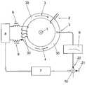
- FIG. 2an embodiment is shown in FIG. 2 wherein a Hall-effect sensor 5 is mounted on the ferromagnetic core 30 , which sensor requires an external power supply in order to be able to work (not shown in the figure).
- the current 1 which is circulating through the conductorlikewise produces a magnetic field 3 in the ferromagnetic core 30 , which is detected by the sensor 5 , the signal obtained being applied to a low pass filter 6 which smoothes the obtained signal.
- the detected and filtered signalhas been referred to with the number 20 , which signal is applied to a comparator 32 which in turn receives a reference signal 21 , and which moreover is connected to a control module 7 , which calculates and generates a compensating current to maintain the signal 20 equal to the value of the reference signal 21 .
- the compensating currentis applied through a power stage 8 and a radiofrequency choke 9 to a winding 33 arranged on the ferromagnetic core 30 , producing in the latter a magnetic field 4 equal and opposite to the field 3 produced by the current 1 , so that a compensation of the magnetic field 3 occurs, so that the ferromagnetic core 30 is not saturated, whereby the current 2 is induced in the conductor without additional insertion loss.
- the current 1 which circulates through the conductoris obtained by means of an external ferromagnetic core 11 on which a coil 34 has been arranged wherein, from the magnetic field produce by current 1 in the ferromagnetic core 11 , said current 1 is produced in the coil 34 , this current 1 being applied, through the radiofrequency choke 9 to the winding 33 , the compensation of the magnetic field being produced in the manner described for the example in the previous figure.
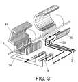
- FIGS. 4 and 5other examples are shown for compensation of the magnetic field 3 produced by current 1 .
- the employis foreseen of two inductive couplers constituted by a double ferromagnetic core 16 and 17 that form the ferromagnetic core 30 .
- the ferromagnetic core 16is a power transformer, not suitable for radiofrequency, that is, it has a very high magnetic permeability at low frequencies and very low at high frequencies; whilst the ferromagnetic core 17 is suitable for radiofrequency; that is, it has a very low magnetic permeability at low frequency and very high at high frequency.
- the detection and obtaining of the compensating currentis carried out simultaneously by locating a winding around the double ring of the coupler.
- the magnetic induction, produced by the current which is passing through the cable,is detected by the winding and produces therein the current which later serves to perform the compensation.
- n coilsare mounted which act as radiofrequency chokes 18 and which enclose both ferromagnetic cores 16 and 17 , a smaller nominal current being achieved in each winding 19 , so that said current carries out the desired compensation of the magnetic field induced by the current 1 which is circulating through the conductor.
- the magnetic field 3is only induced in the ferromagnetic core 16 and the magnetic field 4 in the ferromagnetic core 17 preventing the aforesaid saturation from taking place.
- FIG. 5an alternative embodiment is shown in which n windings are mounted short-circuited by means of a radiofrequency choke 15 .
- This caseis equivalent to the previous one, but it has the advantage of reducing the number of choke coils necessary to carry out the compensation.
- FIG. 6another alternative embodiment is shown of a device which implements the process of the invention.
- a single winding 35is used around the double ferromagnetic core 16 and 17 that forms the ferromagnetic core 30 of the coupling unit.
- This caseis similar to that presented in FIG. 5 , but with the advantage of reducing the number of windings and without having to use choke coils for the compensation.
- the detection and obtaining of the compensating currentare carried out simultaneously.
- the injection of the compensating currentis carried out simultaneously by mounting said winding 35 , whereby a low cost solution is obtained.
Landscapes
- Engineering & Computer Science (AREA)
- Power Engineering (AREA)
- Physics & Mathematics (AREA)
- General Physics & Mathematics (AREA)
- Measuring Instrument Details And Bridges, And Automatic Balancing Devices (AREA)
- Cable Transmission Systems, Equalization Of Radio And Reduction Of Echo (AREA)
- Filters And Equalizers (AREA)
- Near-Field Transmission Systems (AREA)
Abstract
Description
Claims (7)
Applications Claiming Priority (3)
| Application Number | Priority Date | Filing Date | Title |
|---|---|---|---|
| ESP200201357 | 2002-06-12 | ||
| ES200201357AES2197020B1 (en) | 2002-06-12 | 2002-06-12 | PROCEDURE AND DEVICE FOR COMPENSATION OF MAGNETIC FIELD OF LOW FREQUENCY IN AN INDUCTIVE SIGNAL COUPLING UNIT. |
| PCT/ES2003/000283WO2003107561A1 (en) | 2002-06-12 | 2003-06-11 | Device and method for low-frequency magnetic field compensation in an inductive signal coupling unit |
Related Parent Applications (1)
| Application Number | Title | Priority Date | Filing Date |
|---|---|---|---|
| PCT/ES2003/000283ContinuationWO2003107561A1 (en) | 2002-06-12 | 2003-06-11 | Device and method for low-frequency magnetic field compensation in an inductive signal coupling unit |
Publications (2)
| Publication Number | Publication Date |
|---|---|
| US20050122092A1 US20050122092A1 (en) | 2005-06-09 |
| US7002333B2true US7002333B2 (en) | 2006-02-21 |
Family
ID=29724728
Family Applications (1)
| Application Number | Title | Priority Date | Filing Date |
|---|---|---|---|
| US11/010,535Expired - LifetimeUS7002333B2 (en) | 2002-06-12 | 2004-12-13 | Process and device for compensating the low frequency magnetic field in an inductive signal coupling unit |
Country Status (12)
| Country | Link |
|---|---|
| US (1) | US7002333B2 (en) |
| EP (1) | EP1513267A1 (en) |
| JP (1) | JP2006514790A (en) |
| CN (1) | CN1675851A (en) |
| AU (1) | AU2003240856A1 (en) |
| BR (1) | BR0311753A (en) |
| CA (1) | CA2489329A1 (en) |
| EA (1) | EA006417B1 (en) |
| ES (1) | ES2197020B1 (en) |
| IL (1) | IL165722A0 (en) |
| MX (1) | MXPA04011462A (en) |
| WO (1) | WO2003107561A1 (en) |
Cited By (6)
| Publication number | Priority date | Publication date | Assignee | Title |
|---|---|---|---|---|
| KR100359254B1 (en)* | 1997-09-04 | 2002-11-04 | 더 프록터 앤드 갬블 캄파니 | Absorbent article fastening device |
| WO2008033527A3 (en)* | 2006-09-14 | 2008-09-04 | Ambient Corp | Housing for inductive coupler for power line communications |
| US20100134943A1 (en)* | 2008-12-02 | 2010-06-03 | Abb Schweiz Ag | Method for disturbance current compensation for an electrical system, and disturbance current compensation device |
| US20100289595A1 (en)* | 2007-10-02 | 2010-11-18 | Diseno De Sistemas En Silicio, S.A. | Device for inductive multi-injection on multiple conductors |
| US20110215788A1 (en)* | 2008-08-28 | 2011-09-08 | Taiyo Yuden Mobile Technology Co., Ltd. | Dc-dc converter |
| US9513343B2 (en) | 2013-05-08 | 2016-12-06 | Micronas Gmbh | Measuring system |
Families Citing this family (18)
| Publication number | Priority date | Publication date | Assignee | Title |
|---|---|---|---|---|
| US7245201B1 (en) | 2000-08-09 | 2007-07-17 | Current Technologies, Llc | Power line coupling device and method of using the same |
| US7248148B2 (en)* | 2000-08-09 | 2007-07-24 | Current Technologies, Llc | Power line coupling device and method of using the same |
| US7245472B2 (en)* | 2001-05-18 | 2007-07-17 | Curretn Grid, Llc | Medium voltage signal coupling structure for last leg power grid high-speed data network |
| US7307512B2 (en)* | 2005-04-29 | 2007-12-11 | Current Technologies, Llc | Power line coupling device and method of use |
| JP2006352664A (en)* | 2005-06-17 | 2006-12-28 | Mitsubishi Electric Corp | Signal coupling device |
| JP4720575B2 (en)* | 2006-03-29 | 2011-07-13 | Kddi株式会社 | Power line communication device |
| JPWO2008026281A1 (en)* | 2006-08-31 | 2010-01-14 | 三菱電機株式会社 | Inductive coupling device |
| US7876174B2 (en)* | 2007-06-26 | 2011-01-25 | Current Technologies, Llc | Power line coupling device and method |
| US7795994B2 (en)* | 2007-06-26 | 2010-09-14 | Current Technologies, Llc | Power line coupling device and method |
| US20090085726A1 (en)* | 2007-09-27 | 2009-04-02 | Radtke William O | Power Line Communications Coupling Device and Method |
| FR2940557B1 (en)* | 2008-12-23 | 2015-07-24 | Sagem Defense Securite | POWER LINE DIGITAL BUS COUPLER WITH LOW FREQUENCY FLOW CANCELLATION |
| FR2960722B1 (en)* | 2010-05-26 | 2013-03-08 | Sagem Defense Securite | POWER COUPLER / LOW FREQUENCY FLOW CANCELLATION DATA |
| US20130027021A1 (en)* | 2011-07-28 | 2013-01-31 | Abb Inc. | Current sensor |
| DE102018130690B3 (en)* | 2018-12-03 | 2020-03-26 | Bender Gmbh & Co. Kg | Magnetic field measuring device and method for detecting a localization current in a branched AC power supply system |
| US11538628B2 (en) | 2019-12-02 | 2022-12-27 | Panoramic Power Ltd. | Self calibration by signal injection |
| CN111562417B (en)* | 2020-05-26 | 2025-07-15 | 新纳传感系统有限公司 | Current sensor using coil for frequency compensation |
| US20240418751A1 (en)* | 2021-11-04 | 2024-12-19 | China Electric Power Research Institute | Iron core-annular array multi-ring magnetosensitive current sensor and current measurement method |
| CN116500320B (en)* | 2023-06-28 | 2023-09-22 | 广东电网有限责任公司珠海供电局 | Injection current probe for cable fault detection |
Citations (10)
| Publication number | Priority date | Publication date | Assignee | Title |
|---|---|---|---|---|
| US2998564A (en) | 1957-09-03 | 1961-08-29 | Sperry Rand Corp | Magnetic current regulator |
| US4234824A (en)* | 1979-01-10 | 1980-11-18 | Rca Corporation | Combined linearity and side pincushion correction arrangement |
| US4255705A (en)* | 1979-09-24 | 1981-03-10 | General Electric Company | Peak detection and electronic compensation of D. C. saturation magnetization in current transformers used in watt hour meter installations |
| US4346340A (en) | 1980-04-30 | 1982-08-24 | Hackett Jones Francis C | Method and means for controlling the flux density in the core of an inductor |
| US4571569A (en)* | 1983-08-26 | 1986-02-18 | Siemens Aktiengesellschaft | Mounting for an especially current-compensated, ferrite ring-core choke |
| US4862014A (en) | 1986-07-01 | 1989-08-29 | Hughes Aircraft Company | Method and apparatus for controlling the phase of signal driving a ferrimagnetic load |
| EP0521250A2 (en) | 1991-07-03 | 1993-01-07 | Landis & Gyr Business Support AG | Current measuring transducer using a magnetic field sensor |
| EP0661864A1 (en) | 1993-12-28 | 1995-07-05 | AT&T Corp. | Battery feed for telephone line cards |
| WO1998020468A1 (en) | 1996-11-01 | 1998-05-14 | Foster-Miller, Inc. | Modular core, self-powered powerline sensor |
| US6657529B1 (en)* | 1999-07-23 | 2003-12-02 | Koninklijke Philips Electronics N.V. | Magnetic component |
- 2002
- 2002-06-12ESES200201357Apatent/ES2197020B1/ennot_activeExpired - Fee Related
- 2003
- 2003-06-11WOPCT/ES2003/000283patent/WO2003107561A1/ennot_activeApplication Discontinuation
- 2003-06-11CACA002489329Apatent/CA2489329A1/ennot_activeAbandoned
- 2003-06-11CNCN03818987.9Apatent/CN1675851A/enactivePending
- 2003-06-11BRBR0311753-7Apatent/BR0311753A/ennot_activeIP Right Cessation
- 2003-06-11JPJP2004514242Apatent/JP2006514790A/ennot_activeWithdrawn
- 2003-06-11AUAU2003240856Apatent/AU2003240856A1/ennot_activeAbandoned
- 2003-06-11MXMXPA04011462Apatent/MXPA04011462A/enactiveIP Right Grant
- 2003-06-11EPEP03730222Apatent/EP1513267A1/ennot_activeWithdrawn
- 2003-06-11EAEA200401582Apatent/EA006417B1/ennot_activeIP Right Cessation
- 2004
- 2004-12-12ILIL16572204Apatent/IL165722A0/enunknown
- 2004-12-13USUS11/010,535patent/US7002333B2/ennot_activeExpired - Lifetime
Patent Citations (10)
| Publication number | Priority date | Publication date | Assignee | Title |
|---|---|---|---|---|
| US2998564A (en) | 1957-09-03 | 1961-08-29 | Sperry Rand Corp | Magnetic current regulator |
| US4234824A (en)* | 1979-01-10 | 1980-11-18 | Rca Corporation | Combined linearity and side pincushion correction arrangement |
| US4255705A (en)* | 1979-09-24 | 1981-03-10 | General Electric Company | Peak detection and electronic compensation of D. C. saturation magnetization in current transformers used in watt hour meter installations |
| US4346340A (en) | 1980-04-30 | 1982-08-24 | Hackett Jones Francis C | Method and means for controlling the flux density in the core of an inductor |
| US4571569A (en)* | 1983-08-26 | 1986-02-18 | Siemens Aktiengesellschaft | Mounting for an especially current-compensated, ferrite ring-core choke |
| US4862014A (en) | 1986-07-01 | 1989-08-29 | Hughes Aircraft Company | Method and apparatus for controlling the phase of signal driving a ferrimagnetic load |
| EP0521250A2 (en) | 1991-07-03 | 1993-01-07 | Landis & Gyr Business Support AG | Current measuring transducer using a magnetic field sensor |
| EP0661864A1 (en) | 1993-12-28 | 1995-07-05 | AT&T Corp. | Battery feed for telephone line cards |
| WO1998020468A1 (en) | 1996-11-01 | 1998-05-14 | Foster-Miller, Inc. | Modular core, self-powered powerline sensor |
| US6657529B1 (en)* | 1999-07-23 | 2003-12-02 | Koninklijke Philips Electronics N.V. | Magnetic component |
Cited By (13)
| Publication number | Priority date | Publication date | Assignee | Title |
|---|---|---|---|---|
| KR100359254B1 (en)* | 1997-09-04 | 2002-11-04 | 더 프록터 앤드 갬블 캄파니 | Absorbent article fastening device |
| US7859378B2 (en) | 2006-09-14 | 2010-12-28 | Ambient Corporation | Housing for inductive coupler for power line communications |
| WO2008033527A3 (en)* | 2006-09-14 | 2008-09-04 | Ambient Corp | Housing for inductive coupler for power line communications |
| EA013485B1 (en)* | 2006-09-14 | 2010-04-30 | Амбиент Корпорэйшн | Housing of an inductive coupler using for power line communications |
| US8269574B2 (en)* | 2007-10-02 | 2012-09-18 | Marvell Hispania, S.L.U. | Device for inductive multi-injection on multiple conductors |
| US20100289595A1 (en)* | 2007-10-02 | 2010-11-18 | Diseno De Sistemas En Silicio, S.A. | Device for inductive multi-injection on multiple conductors |
| US20110109399A1 (en)* | 2007-10-02 | 2011-05-12 | Jorge Vicente Blasco Claret | Device for inductive multi-injection on multiple conductors |
| US8274341B2 (en)* | 2007-10-02 | 2012-09-25 | Marvell Hispania, S.L.U. | Device for inductive multi-injection on multiple conductors |
| US20110215788A1 (en)* | 2008-08-28 | 2011-09-08 | Taiyo Yuden Mobile Technology Co., Ltd. | Dc-dc converter |
| US8258772B2 (en)* | 2008-08-28 | 2012-09-04 | Fujitsu Limited | DC-DC converter |
| US20100134943A1 (en)* | 2008-12-02 | 2010-06-03 | Abb Schweiz Ag | Method for disturbance current compensation for an electrical system, and disturbance current compensation device |
| US8369059B2 (en)* | 2008-12-02 | 2013-02-05 | Abb Schweiz Ag | Method for disturbance current compensation for an electrical system, and disturbance current compensation device |
| US9513343B2 (en) | 2013-05-08 | 2016-12-06 | Micronas Gmbh | Measuring system |
Also Published As
| Publication number | Publication date |
|---|---|
| AU2003240856A1 (en) | 2003-12-31 |
| EP1513267A1 (en) | 2005-03-09 |
| ES2197020A1 (en) | 2003-12-16 |
| MXPA04011462A (en) | 2005-02-14 |
| EA200401582A1 (en) | 2005-08-25 |
| BR0311753A (en) | 2005-03-08 |
| EA006417B1 (en) | 2005-12-29 |
| ES2197020B1 (en) | 2005-03-01 |
| CA2489329A1 (en) | 2003-12-24 |
| US20050122092A1 (en) | 2005-06-09 |
| WO2003107561A1 (en) | 2003-12-24 |
| JP2006514790A (en) | 2006-05-11 |
| IL165722A0 (en) | 2006-01-15 |
| CN1675851A (en) | 2005-09-28 |
Similar Documents
| Publication | Publication Date | Title |
|---|---|---|
| US7002333B2 (en) | Process and device for compensating the low frequency magnetic field in an inductive signal coupling unit | |
| KR100569748B1 (en) | Powerline noise filter | |
| US7061370B2 (en) | High current inductive coupler and current transformer for power lines | |
| US7898827B2 (en) | Active EMI filtering using magnetic coupling cancellation | |
| US7170367B2 (en) | Inductive coupler for power line communications | |
| CN100423418C (en) | Current-compensated choke and circuit arrangement comprising the current-compensated choke | |
| WO2006064499B1 (en) | Magnetic induction device | |
| US7164331B2 (en) | RF choke for cable system | |
| HK1071244A (en) | Device and method for low-frequency magnetic field compensation in an inductive signal coupling unit | |
| Oates | The design and use of Rogowski coils | |
| EP1641138A1 (en) | Signal filling/extraction device | |
| KR20050020993A (en) | Device and method for low frequency magnetic field compensation in an inductive signal coupling unit | |
| JP3756774B2 (en) | Impedance adjuster | |
| WO1999049572A1 (en) | Ac power passing rf choke | |
| JP5140022B2 (en) | Signal coupling device for power line carrier communication | |
| JP2002290288A (en) | Power-line carrier communication network system | |
| CN203480011U (en) | Magnetic resonance imaging device |
Legal Events
| Date | Code | Title | Description |
|---|---|---|---|
| AS | Assignment | Owner name:DISENO DE SISTEMAS EN SILICIO, S.A., SPAIN Free format text:ASSIGNMENT OF ASSIGNORS INTEREST;ASSIGNORS:BLASCO CLARET, JORGE VICENTE;POVEDA LERMA, ANTONIO;REEL/FRAME:016081/0620 Effective date:20040730 | |
| STCF | Information on status: patent grant | Free format text:PATENTED CASE | |
| REMI | Maintenance fee reminder mailed | ||
| FPAY | Fee payment | Year of fee payment:4 | |
| SULP | Surcharge for late payment | ||
| AS | Assignment | Owner name:MARVELL HISPANIA, S. L. U., SPAIN Free format text:ASSIGNMENT OF ASSIGNORS INTEREST;ASSIGNOR:DISENO DE SISTEMAS EN SILICIO, S. A.;REEL/FRAME:024963/0854 Effective date:20100730 | |
| FPAY | Fee payment | Year of fee payment:8 | |
| AS | Assignment | Owner name:MAXLINEAR HISPANIA, S.L.U., SPAIN Free format text:CHANGE OF NAME;ASSIGNOR:MARVELL HISPANIA, S.L.U.;REEL/FRAME:043563/0064 Effective date:20170404 | |
| MAFP | Maintenance fee payment | Free format text:PAYMENT OF MAINTENANCE FEE, 12TH YEAR, LARGE ENTITY (ORIGINAL EVENT CODE: M1553) Year of fee payment:12 | |
| FEPP | Fee payment procedure | Free format text:PAYOR NUMBER ASSIGNED (ORIGINAL EVENT CODE: ASPN) Free format text:PAT HOLDER NO LONGER CLAIMS SMALL ENTITY STATUS, ENTITY STATUS SET TO UNDISCOUNTED (ORIGINAL EVENT CODE: STOL) |