US7001671B2 - Kinetic sprayed electrical contacts on conductive substrates - Google Patents
Kinetic sprayed electrical contacts on conductive substratesDownload PDFInfo
- Publication number
- US7001671B2 US7001671B2US10/676,393US67639303AUS7001671B2US 7001671 B2US7001671 B2US 7001671B2US 67639303 AUS67639303 AUS 67639303AUS 7001671 B2US7001671 B2US 7001671B2
- Authority
- US
- United States
- Prior art keywords
- particles
- tin
- embedded
- electrical connector
- copper
- Prior art date
- Legal status (The legal status is an assumption and is not a legal conclusion. Google has not performed a legal analysis and makes no representation as to the accuracy of the status listed.)
- Expired - Lifetime, expires
Links
- 239000000758substrateSubstances0.000titledescription30
- 239000002245particleSubstances0.000claimsabstractdescription107
- 239000004020conductorSubstances0.000claimsabstractdescription48
- ATJFFYVFTNAWJD-UHFFFAOYSA-NTinChemical compound[Sn]ATJFFYVFTNAWJD-UHFFFAOYSA-N0.000claimsdescription31
- 229910052718tinInorganic materials0.000claimsdescription31
- RYGMFSIKBFXOCR-UHFFFAOYSA-NCopperChemical compound[Cu]RYGMFSIKBFXOCR-UHFFFAOYSA-N0.000claimsdescription28
- 229910052802copperInorganic materials0.000claimsdescription28
- 239000010949copperSubstances0.000claimsdescription28
- 229910052751metalInorganic materials0.000claimsdescription9
- 239000002184metalSubstances0.000claimsdescription9
- KUNSUQLRTQLHQQ-UHFFFAOYSA-Ncopper tinChemical compound[Cu].[Sn]KUNSUQLRTQLHQQ-UHFFFAOYSA-N0.000claimsdescription6
- 239000000203mixtureSubstances0.000claimsdescription6
- 229910045601alloyInorganic materials0.000claimsdescription5
- 239000000956alloySubstances0.000claimsdescription5
- PCHJSUWPFVWCPO-UHFFFAOYSA-NgoldChemical compound[Au]PCHJSUWPFVWCPO-UHFFFAOYSA-N0.000claimsdescription4
- 229910052737goldInorganic materials0.000claimsdescription4
- 239000010931goldSubstances0.000claimsdescription4
- BASFCYQUMIYNBI-UHFFFAOYSA-NplatinumChemical compound[Pt]BASFCYQUMIYNBI-UHFFFAOYSA-N0.000claimsdescription4
- 229910001369BrassInorganic materials0.000claimsdescription3
- BQCADISMDOOEFD-UHFFFAOYSA-NSilverChemical compound[Ag]BQCADISMDOOEFD-UHFFFAOYSA-N0.000claimsdescription3
- QCEUXSAXTBNJGO-UHFFFAOYSA-N[Ag].[Sn]Chemical compound[Ag].[Sn]QCEUXSAXTBNJGO-UHFFFAOYSA-N0.000claimsdescription3
- 229910052782aluminiumInorganic materials0.000claimsdescription3
- XAGFODPZIPBFFR-UHFFFAOYSA-NaluminiumChemical compound[Al]XAGFODPZIPBFFR-UHFFFAOYSA-N0.000claimsdescription3
- 239000010951brassSubstances0.000claimsdescription3
- LQBJWKCYZGMFEV-UHFFFAOYSA-Nlead tinChemical compound[Sn].[Pb]LQBJWKCYZGMFEV-UHFFFAOYSA-N0.000claimsdescription3
- 229910052709silverInorganic materials0.000claimsdescription3
- 239000004332silverSubstances0.000claimsdescription3
- 239000010935stainless steelSubstances0.000claimsdescription3
- 229910001220stainless steelInorganic materials0.000claimsdescription3
- 239000011135tinSubstances0.000claimsdescription3
- WFKWXMTUELFFGS-UHFFFAOYSA-NtungstenChemical compound[W]WFKWXMTUELFFGS-UHFFFAOYSA-N0.000claimsdescription3
- 229910052721tungstenInorganic materials0.000claimsdescription3
- 239000010937tungstenSubstances0.000claimsdescription3
- 229910001092metal group alloyInorganic materials0.000claims2
- 238000000576coating methodMethods0.000description17
- 239000010410layerSubstances0.000description17
- 238000000034methodMethods0.000description16
- 230000008569processEffects0.000description11
- 239000002344surface layerSubstances0.000description9
- 239000007921spraySubstances0.000description7
- 238000005507sprayingMethods0.000description7
- 239000007789gasSubstances0.000description6
- 239000011248coating agentSubstances0.000description4
- 238000009713electroplatingMethods0.000description4
- 238000004519manufacturing processMethods0.000description4
- 238000000151depositionMethods0.000description3
- 239000000463materialSubstances0.000description3
- 230000008018meltingEffects0.000description3
- 238000002844meltingMethods0.000description3
- 238000012546transferMethods0.000description3
- 229910000881Cu alloyInorganic materials0.000description2
- 230000008859changeEffects0.000description2
- 230000008021depositionEffects0.000description2
- 238000005516engineering processMethods0.000description2
- 230000013011matingEffects0.000description2
- 230000003647oxidationEffects0.000description2
- 238000007254oxidation reactionMethods0.000description2
- 239000000843powderSubstances0.000description2
- 238000012545processingMethods0.000description2
- 239000000523sampleSubstances0.000description2
- 238000001878scanning electron micrographMethods0.000description2
- 239000002699waste materialSubstances0.000description2
- 101001126084Homo sapiens Piwi-like protein 2Proteins0.000description1
- 102100029365Piwi-like protein 2Human genes0.000description1
- 229910001128Sn alloyInorganic materials0.000description1
- GYMWQLRSSDFGEQ-ADRAWKNSSA-N[(3e,8r,9s,10r,13s,14s,17r)-13-ethyl-17-ethynyl-3-hydroxyimino-1,2,6,7,8,9,10,11,12,14,15,16-dodecahydrocyclopenta[a]phenanthren-17-yl] acetate;(8r,9s,13s,14s,17r)-17-ethynyl-13-methyl-7,8,9,11,12,14,15,16-octahydro-6h-cyclopenta[a]phenanthrene-3,17-diolChemical compoundOC1=CC=C2[C@H]3CC[C@](C)([C@](CC4)(O)C#C)[C@@H]4[C@@H]3CCC2=C1.O/N=C/1CC[C@@H]2[C@H]3CC[C@](CC)([C@](CC4)(OC(C)=O)C#C)[C@@H]4[C@@H]3CCC2=C\1GYMWQLRSSDFGEQ-ADRAWKNSSA-N0.000description1
- QVGXLLKOCUKJST-UHFFFAOYSA-Natomic oxygenChemical compound[O]QVGXLLKOCUKJST-UHFFFAOYSA-N0.000description1
- 230000009286beneficial effectEffects0.000description1
- 230000008901benefitEffects0.000description1
- 230000015556catabolic processEffects0.000description1
- 239000002131composite materialSubstances0.000description1
- 239000011246composite particleSubstances0.000description1
- 238000006731degradation reactionMethods0.000description1
- 238000010438heat treatmentMethods0.000description1
- 238000010348incorporationMethods0.000description1
- 239000002905metal composite materialSubstances0.000description1
- 150000002739metalsChemical class0.000description1
- 238000012986modificationMethods0.000description1
- 230000004048modificationEffects0.000description1
- 239000001301oxygenSubstances0.000description1
- 229910052760oxygenInorganic materials0.000description1
- 239000012071phaseSubstances0.000description1
- 230000000704physical effectEffects0.000description1
- 238000007747platingMethods0.000description1
- 229910052697platinumInorganic materials0.000description1
- 239000007790solid phaseSubstances0.000description1
- 230000035882stressEffects0.000description1
- 230000008646thermal stressEffects0.000description1
- 230000007704transitionEffects0.000description1
Images


Classifications
- H—ELECTRICITY
- H01—ELECTRIC ELEMENTS
- H01R—ELECTRICALLY-CONDUCTIVE CONNECTIONS; STRUCTURAL ASSOCIATIONS OF A PLURALITY OF MUTUALLY-INSULATED ELECTRICAL CONNECTING ELEMENTS; COUPLING DEVICES; CURRENT COLLECTORS
- H01R13/00—Details of coupling devices of the kinds covered by groups H01R12/70 or H01R24/00 - H01R33/00
- H01R13/02—Contact members
- H01R13/03—Contact members characterised by the material, e.g. plating, or coating materials
- H—ELECTRICITY
- H01—ELECTRIC ELEMENTS
- H01R—ELECTRICALLY-CONDUCTIVE CONNECTIONS; STRUCTURAL ASSOCIATIONS OF A PLURALITY OF MUTUALLY-INSULATED ELECTRICAL CONNECTING ELEMENTS; COUPLING DEVICES; CURRENT COLLECTORS
- H01R4/00—Electrically-conductive connections between two or more conductive members in direct contact, i.e. touching one another; Means for effecting or maintaining such contact; Electrically-conductive connections having two or more spaced connecting locations for conductors and using contact members penetrating insulation
- H01R4/58—Electrically-conductive connections between two or more conductive members in direct contact, i.e. touching one another; Means for effecting or maintaining such contact; Electrically-conductive connections having two or more spaced connecting locations for conductors and using contact members penetrating insulation characterised by the form or material of the contacting members
- Y—GENERAL TAGGING OF NEW TECHNOLOGICAL DEVELOPMENTS; GENERAL TAGGING OF CROSS-SECTIONAL TECHNOLOGIES SPANNING OVER SEVERAL SECTIONS OF THE IPC; TECHNICAL SUBJECTS COVERED BY FORMER USPC CROSS-REFERENCE ART COLLECTIONS [XRACs] AND DIGESTS
- Y10—TECHNICAL SUBJECTS COVERED BY FORMER USPC
- Y10T—TECHNICAL SUBJECTS COVERED BY FORMER US CLASSIFICATION
- Y10T428/00—Stock material or miscellaneous articles
- Y10T428/12—All metal or with adjacent metals
- Y10T428/12014—All metal or with adjacent metals having metal particles
- Y10T428/12028—Composite; i.e., plural, adjacent, spatially distinct metal components [e.g., layers, etc.]
- Y10T428/12063—Nonparticulate metal component
- Y10T428/12104—Particles discontinuous
- Y—GENERAL TAGGING OF NEW TECHNOLOGICAL DEVELOPMENTS; GENERAL TAGGING OF CROSS-SECTIONAL TECHNOLOGIES SPANNING OVER SEVERAL SECTIONS OF THE IPC; TECHNICAL SUBJECTS COVERED BY FORMER USPC CROSS-REFERENCE ART COLLECTIONS [XRACs] AND DIGESTS
- Y10—TECHNICAL SUBJECTS COVERED BY FORMER USPC
- Y10T—TECHNICAL SUBJECTS COVERED BY FORMER US CLASSIFICATION
- Y10T428/00—Stock material or miscellaneous articles
- Y10T428/12—All metal or with adjacent metals
- Y10T428/12486—Laterally noncoextensive components [e.g., embedded, etc.]
- Y—GENERAL TAGGING OF NEW TECHNOLOGICAL DEVELOPMENTS; GENERAL TAGGING OF CROSS-SECTIONAL TECHNOLOGIES SPANNING OVER SEVERAL SECTIONS OF THE IPC; TECHNICAL SUBJECTS COVERED BY FORMER USPC CROSS-REFERENCE ART COLLECTIONS [XRACs] AND DIGESTS
- Y10—TECHNICAL SUBJECTS COVERED BY FORMER USPC
- Y10T—TECHNICAL SUBJECTS COVERED BY FORMER US CLASSIFICATION
- Y10T428/00—Stock material or miscellaneous articles
- Y10T428/12—All metal or with adjacent metals
- Y10T428/12493—Composite; i.e., plural, adjacent, spatially distinct metal components [e.g., layers, joint, etc.]
- Y10T428/12708—Sn-base component
- Y—GENERAL TAGGING OF NEW TECHNOLOGICAL DEVELOPMENTS; GENERAL TAGGING OF CROSS-SECTIONAL TECHNOLOGIES SPANNING OVER SEVERAL SECTIONS OF THE IPC; TECHNICAL SUBJECTS COVERED BY FORMER USPC CROSS-REFERENCE ART COLLECTIONS [XRACs] AND DIGESTS
- Y10—TECHNICAL SUBJECTS COVERED BY FORMER USPC
- Y10T—TECHNICAL SUBJECTS COVERED BY FORMER US CLASSIFICATION
- Y10T428/00—Stock material or miscellaneous articles
- Y10T428/12—All metal or with adjacent metals
- Y10T428/12493—Composite; i.e., plural, adjacent, spatially distinct metal components [e.g., layers, joint, etc.]
- Y10T428/12736—Al-base component
- Y—GENERAL TAGGING OF NEW TECHNOLOGICAL DEVELOPMENTS; GENERAL TAGGING OF CROSS-SECTIONAL TECHNOLOGIES SPANNING OVER SEVERAL SECTIONS OF THE IPC; TECHNICAL SUBJECTS COVERED BY FORMER USPC CROSS-REFERENCE ART COLLECTIONS [XRACs] AND DIGESTS
- Y10—TECHNICAL SUBJECTS COVERED BY FORMER USPC
- Y10T—TECHNICAL SUBJECTS COVERED BY FORMER US CLASSIFICATION
- Y10T428/00—Stock material or miscellaneous articles
- Y10T428/12—All metal or with adjacent metals
- Y10T428/12493—Composite; i.e., plural, adjacent, spatially distinct metal components [e.g., layers, joint, etc.]
- Y10T428/12771—Transition metal-base component
- Y10T428/12861—Group VIII or IB metal-base component
- Y10T428/12903—Cu-base component
- Y—GENERAL TAGGING OF NEW TECHNOLOGICAL DEVELOPMENTS; GENERAL TAGGING OF CROSS-SECTIONAL TECHNOLOGIES SPANNING OVER SEVERAL SECTIONS OF THE IPC; TECHNICAL SUBJECTS COVERED BY FORMER USPC CROSS-REFERENCE ART COLLECTIONS [XRACs] AND DIGESTS
- Y10—TECHNICAL SUBJECTS COVERED BY FORMER USPC
- Y10T—TECHNICAL SUBJECTS COVERED BY FORMER US CLASSIFICATION
- Y10T428/00—Stock material or miscellaneous articles
- Y10T428/24—Structurally defined web or sheet [e.g., overall dimension, etc.]
- Y10T428/24802—Discontinuous or differential coating, impregnation or bond [e.g., artwork, printing, retouched photograph, etc.]
- Y10T428/24851—Intermediate layer is discontinuous or differential
- Y—GENERAL TAGGING OF NEW TECHNOLOGICAL DEVELOPMENTS; GENERAL TAGGING OF CROSS-SECTIONAL TECHNOLOGIES SPANNING OVER SEVERAL SECTIONS OF THE IPC; TECHNICAL SUBJECTS COVERED BY FORMER USPC CROSS-REFERENCE ART COLLECTIONS [XRACs] AND DIGESTS
- Y10—TECHNICAL SUBJECTS COVERED BY FORMER USPC
- Y10T—TECHNICAL SUBJECTS COVERED BY FORMER US CLASSIFICATION
- Y10T428/00—Stock material or miscellaneous articles
- Y10T428/24—Structurally defined web or sheet [e.g., overall dimension, etc.]
- Y10T428/24802—Discontinuous or differential coating, impregnation or bond [e.g., artwork, printing, retouched photograph, etc.]
- Y10T428/24917—Discontinuous or differential coating, impregnation or bond [e.g., artwork, printing, retouched photograph, etc.] including metal layer
- Y—GENERAL TAGGING OF NEW TECHNOLOGICAL DEVELOPMENTS; GENERAL TAGGING OF CROSS-SECTIONAL TECHNOLOGIES SPANNING OVER SEVERAL SECTIONS OF THE IPC; TECHNICAL SUBJECTS COVERED BY FORMER USPC CROSS-REFERENCE ART COLLECTIONS [XRACs] AND DIGESTS
- Y10—TECHNICAL SUBJECTS COVERED BY FORMER USPC
- Y10T—TECHNICAL SUBJECTS COVERED BY FORMER US CLASSIFICATION
- Y10T428/00—Stock material or miscellaneous articles
- Y10T428/25—Web or sheet containing structurally defined element or component and including a second component containing structurally defined particles
Definitions
- the present inventionis directed to electrical contacts that comprise spaced particles embedded into the surface of conductors in which the particles have been kinetically sprayed onto the conductors with sufficient energy to form direct mechanical bonds between the particles and the conductors in a pre-selected location and particle number density that promotes high surface-to-surface contact and reduced contact resistance between the conductors.
- the method of making such electrical contactsis also provided.
- Most electrical contactsare copper or copper alloy conductors with a tin-plated surface layer.
- the tin surface layeris a single continuous layer directly bonded to a clean non-oxidized copper substrate in order to promote maximum conductance between conductors while limiting resistance from the tin-copper metallic bond.
- Tinis used as a surface layer since it is substantially softer than copper and may be recurrently wiped to provide a fresh de-oxidized surface for metal-to-metal connection between conductors.
- Electrodeshave been traditionally made by electroplating a layer of tin to copper substrates followed by stamping out individual conductors.
- the copper substratesmust be cleaned prior to placement in the electroplating bath to remove any oxidized surface layers that may otherwise create additional electrical resistance.
- the substratesare coated to a thickness of about 3 to 5 microns of tin.
- the threshold thickness for electroplating tin onto copperis about 5 microns.
- Alkimov et al.disclosed producing dense continuous layer coatings with powder particles having a particle size of from 1 to 50 microns using a supersonic spray.
- Van Steenkiste articlereported on work conducted by the National Center for Manufacturing Sciences (NCMS) to improve on the earlier Alkimov process and apparatus. Van Steenkiste et al. demonstrated that Alkimov's apparatus and process could be modified to produce kinetic spray coatings using particle sizes of greater than 50 microns and up to about 106 microns.
- the present inventionis directed to kinetic spraying electrically conductive materials onto conductive substrates. More particularly, the present invention is directed to electrical contacts that comprise spaced electrically conductive particles embedded into the surface of conductors in which the particles have been kinetically sprayed onto the conductors with sufficient energy to form direct mechanical bonds between the particles and the conductors in a pre-selected location and particle number density that promotes high surface-to-surface contact and reduced contact resistance between the conductors.
- the particle number densitydefines the quantity of spaced particles deposited within a selected location.
- the present inventorsused this process to embed a large number of spaced apart particles in the surface of conductors to provide multiple contact points that are particularly useful for electrical contacts.
- a large number of spaced particles embedded in the surface of the conductorsprovide a structure having a surface layer with a plurality of particles forming ridges and valleys. Each embedded particle defines a ridge, and the space in between particles defines a valley.
- the ridgesprovide multiple contact points for conductance while the spaces provide multiple avenues for the removal of debris produced from repeated fretting.
- the discontinuous nature of the particle coating caused by the method of applicationleads to an electrically conductive contact that can with stand repeated fretting, as discussed further below.
- the present inventionprovides the means for controlling the location of deposition of kinetic sprayed particles and the particle number density deposited in that location on the conductive substrate by simply controlling the feed rate of particles into the gas stream and the traverse speed of the substrate across the apparatus and/or nozzle. By doing so, the spray of conductive materials is controlled so that particles are only deposited on those portions that are to be stamped out as conductors.
- the present processeliminates this step.
- the impact of the initial kinetic sprayed particles on the surfaceis sufficiently forceful to fracture any oxide layer on the surface.
- the subsequent particles striking the now cleaned surfacestick.
- electrical contacts produced by kinetic spraying spaced electrically conductive particlesare particularly useful.
- the present inventionprovides that particles can be kinetic sprayed onto conductors with sufficient energy to form direct mechanical bonds between the particles and the conductors in a pre-selected location and particle number density that promotes high surface-to-surface contact between the conductors with reduced contact resistance.
- FIG. 1is a scanning electron micrograph of an electrical contact of the present invention comprising a copper conductor with kinetic sprayed tin particles, having an original particle diameter of about 50 to 65 microns, embedded on its surface;
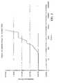
- FIG. 2is a chart that shows the contact resistance as a function of fretting cycles of a prior art electroplated tin electrical contact
- FIG. 3is a chart that shows the contact resistance as a function of fretting cycles of a tin-copper electrical contact made according to the present invention.
- An electrical contact of the present inventionpreferably has a contact resistance of less than about 10 milli-ohms and more preferably less than about 2 milli-ohms (when measured with a 1 Newton load and a 1.6 mm radius gold probe per ASTM B667).
- the electrical contactcomprises first and second mated conductors. While more than two conductors may be used to form an electrical contact, two are preferred.
- the conductorsare stamped out of conductive substrates made of any suitable conductive material including, but not limited, to copper, copper alloys, aluminum, brass, stainless steel and tungsten. It is preferred, however, that the substrate be made of copper.
- At least one of the conductorscomprises a plurality of spaced particles that have been embedded into the surface of the conductor in a pre-selected location and particle number density.
- the spaced particlesare embedded and bonded into the surface using the kinetic spray process as described herein and as further generally described in U.S. Pat. No. 6,139,913 and the Van Steenkiste et al article (“Kinetic Spray Coatings,” published in Surface and Coatings Technology, Vol. III, pages 62–71, Jan. 10, 1999), both of which are incorporated herein by reference.
- the particlesmay be selected from any electrically conductive particle. Due to the impact of the particle on the substrate, it has been found that it is no longer necessary to select the particle from a material that is softer than the material being selected for the conductors.
- Any electrically conductive particle, including mixtures thereof,may be used in the present invention, including for example, particles comprising monoliths, composites and alloys.
- Suitable monolithic conductive particlesinclude, for example, tin, silver, gold, and platinum;
- suitable composite particlesinclude, for example, metal/metal composites of metals that do not easily form alloys; and suitable alloys include, for example, alloys of tin, such as tin-copper, tin-silver, tin-lead and the like.
- tin or mixtures with tinare preferred. It has been found that particles having a nominal diameter of about 25 microns to about 106 microns are suitable, but the preferred range has a nominal diameter of greater than about 50 microns and more preferably have a nominal diameter of about 75 microns.
- Each embedded particledue to the kinetic impact force, flattens into a nub-like structure with an aspect ratio of about 5 to 1, reducing in height to about one third of its original diameter.
- the nubsare discontinuous and define ridges for conductance when mating the conductors and the spaces in between the nubs define valleys for removal of debris produced from the rubbing, or “fretting,” that occurs from relative movement between mated contacts.
- FIG. 1A scanning electron micrograph of the surface of an electrical contact of the present invention is shown in FIG. 1 .
- the lumps (or nubs)are the tin particles and the substrate is copper.
- the original particle sizewas about 50 to 65 microns.
- Electrical contacts of the present inventionare preferably made using the apparatus disclosed in U.S. Pat. No. 6,139,913.
- the process usedis modified from that disclosed in the prior patent in order to achieve the discontinuous layer of particles contemplated in the present invention.
- the operational parametersare modified to obtain an exit velocity of the particles from the de Laval-type nozzle of between about 300 m/s (meters per second) to less than about 1000 m/s.
- the substrateis also moved in relation to the apparatus and/or the nozzle to provide movement along the surface of the substrate at a traverse speed of about 1 m/s to about 10 m/s, and preferably about 2 m/s, adjusted as necessary to obtain the discontinuous particle layer of the present invention.
- the particle feed ratemay also be adjusted to obtain the desired particle number density.
- the temperature of the gas streamis also modified to be in the range of about 100° C. to about 550° C., ie. lower than in a typical kinetic spray process. More preferably, the temperature range is from 100° C. to 300° C., with about 200° C. being the most preferred operating temperature especially for kinetic spraying tin onto copper.
- the temperature of the particles in the gas streamwill vary depending on the particle size being kinetic sprayed and the main gas stream temperature. Since these temperatures are substantially less than the melting point of the original particles, even upon impact, there is no change of the solid phase of the original particles due to transfer of kinetic and thermal energy, and therefore no change in their original physical properties.
- the electrical contacthas a contact resistance of about 1 to 2 milli-ohms and comprises first and second mating copper conductors.
- Each of these copper conductorsfurther comprises a plurality of spaced tin particles kinetic sprayed onto the surface of the conductors in a pre-selected location and particle number density.
- the kinetic sprayed particleshave an original nominal particle diameter of about 75 microns and are embedded into the surface of each conductor forming a direct metallic bond between the tin and copper.
- the direct bondis formed when the kinetic sprayed particle impacts the copper surface and fractures the oxidized surface layer and subsequently forms a direct metal-to-metal bond between the tin particle and the copper substrate.
- Each embedded tin particlehas a nub-like shape with the average height of each particle being about 25 microns from the surface of the copper substrate.
- tin particlesare introduced into a focused air stream, pre-heated to about 200° C., and accelerated through a de Laval-type nozzle to produce an exit velocity of about 300 m/s (meters per second) to less than about 1000 m/s.
- the entrained particlesgain kinetic and thermal energy during transfer.
- the particlesare accelerated through the nozzle as the surface of a copper substrate begins to move across the apparatus and/or nozzle at a traverse speed of about 2 m/s within a pre-selected location on the substrate that approximates the shape of the copper conductor contemplated to be stamped out of the copper substrate.
- the tin particlesare directed and impacted continuously onto the copper substrate forming a plurality of spaced electrically conductive particles.
- the kinetic sprayed particlestransfer substantially all of their kinetic and thermal energy to the copper substrate, fracturing any oxidation layer on the surface of the copper substrate while simultaneously mechanically deforming the tin particle onto the surface.
- the particlesbecome embedded and mechanically bond the tin to the copper via a metallic bond.
- the resulting deformed particleshave a nub-like shape with an aspect ratio of about 5 to 1.
- FIGS. 2 and 3Performance results of an electrical contact produced according to the present invention and a standard electroplated contact are depicted in FIGS. 2 and 3 .
- FIG. 2shows the contact resistance as a function of fretting cycles of a prior art electrical contact having two copper conductors electroplated with tin. The electroplating forms a continuous layer as opposed to the discontinuous layer formed by the present process. The results show that the contact initially maintained a resistance of less than about 1 milli-ohm for the first 50 cycles, but then resistance began increasing to reach about 10 milli-ohms at about 120 cycles and over 100 milli-ohms at about 1000 cycles.
- FIG. 1shows the contact initially maintained a resistance of less than about 1 milli-ohm for the first 50 cycles, but then resistance began increasing to reach about 10 milli-ohms at about 120 cycles and over 100 milli-ohms at about 1000 cycles.
- FIGS. 2 and 3shows the contact resistance as a function of fretting cycles of a tin-copper electrical contact made according to the present invention in which two copper conductors were kinetic sprayed with tin particles.
- the resultsshow that the contact initially maintained a resistance of less than about 1 milli-ohm for about 5000 cycles before resistance began increasing.
- the present inventioncan produce improved electrical contacts that maintain a low resistance over time.
Landscapes
- Other Surface Treatments For Metallic Materials (AREA)
- Coating By Spraying Or Casting (AREA)
- Manufacturing Of Printed Wiring (AREA)
- Manufacture Of Switches (AREA)
Abstract
Description
| CONTACT RESISTANCE | |||
| Spot | Spot | Spot | Spot | Spot | Aver- | |||
| 1 | 2 | 3 | 4 | 5 | age | Standard | ||
| Sample | (g) | (mΩ) | (mΩ) | (mΩ) | (mΩ) | (mΩ) | (mΩ) | |
| 801a |
| 100 | 1.43 | 0.85 | 1.62 | 1.17 | 0.88 | 1.19 | 0.34 | |
| (150° C.) | 200 | 0.76 | 0.52 | 1.15 | 0.80 | 0.57 | 0.78 | 0.23 |
| 100 | 0.92 | 0.91 | 0.86 | 0.99 | 1.17 | 0.97 | 0.12 | |
| (200° C.) | 200 | 0.62 | 0.60 | 0.64 | 0.55 | 0.82 | 0.67 | 0.09 |
| 901a | 100 | 1.14 | 1.00 | 1.30 | 1.20 | 1.75 | 1.28 | 0.29 |
| (150° C.) | 200 | NT | NT | 0.85 | 0.90 | 1.20 | 0.98 | 0.19 |
| 100 | 2.19 | 0.89 | 0.89 | 0.95 | 1.36 | 1.26 | 0.56 | |
| (100° C.) | 200 | NT | NT | NT | NT | NT | NT | |
Claims (19)
Priority Applications (1)
| Application Number | Priority Date | Filing Date | Title |
|---|---|---|---|
| US10/676,393US7001671B2 (en) | 2001-10-09 | 2003-10-01 | Kinetic sprayed electrical contacts on conductive substrates |
Applications Claiming Priority (2)
| Application Number | Priority Date | Filing Date | Title |
|---|---|---|---|
| US09/974,243US6685988B2 (en) | 2001-10-09 | 2001-10-09 | Kinetic sprayed electrical contacts on conductive substrates |
| US10/676,393US7001671B2 (en) | 2001-10-09 | 2003-10-01 | Kinetic sprayed electrical contacts on conductive substrates |
Related Parent Applications (1)
| Application Number | Title | Priority Date | Filing Date |
|---|---|---|---|
| US09/974,243DivisionUS6685988B2 (en) | 2001-10-09 | 2001-10-09 | Kinetic sprayed electrical contacts on conductive substrates |
Publications (2)
| Publication Number | Publication Date |
|---|---|
| US20040072008A1 US20040072008A1 (en) | 2004-04-15 |
| US7001671B2true US7001671B2 (en) | 2006-02-21 |
Family
ID=25521786
Family Applications (2)
| Application Number | Title | Priority Date | Filing Date |
|---|---|---|---|
| US09/974,243Expired - Fee RelatedUS6685988B2 (en) | 2001-10-09 | 2001-10-09 | Kinetic sprayed electrical contacts on conductive substrates |
| US10/676,393Expired - LifetimeUS7001671B2 (en) | 2001-10-09 | 2003-10-01 | Kinetic sprayed electrical contacts on conductive substrates |
Family Applications Before (1)
| Application Number | Title | Priority Date | Filing Date |
|---|---|---|---|
| US09/974,243Expired - Fee RelatedUS6685988B2 (en) | 2001-10-09 | 2001-10-09 | Kinetic sprayed electrical contacts on conductive substrates |
Country Status (3)
| Country | Link |
|---|---|
| US (2) | US6685988B2 (en) |
| EP (1) | EP1303007B1 (en) |
| DE (1) | DE60204198T2 (en) |
Cited By (3)
| Publication number | Priority date | Publication date | Assignee | Title |
|---|---|---|---|---|
| US20100031627A1 (en)* | 2008-08-07 | 2010-02-11 | United Technologies Corp. | Heater Assemblies, Gas Turbine Engine Systems Involving Such Heater Assemblies and Methods for Manufacturing Such Heater Assemblies |
| US20110244262A1 (en)* | 2010-03-31 | 2011-10-06 | Hitachi, Ltd. | Metal Bonding Member and Fabrication Method of the Same |
| US20220314322A1 (en)* | 2021-04-06 | 2022-10-06 | Eaton Intelligent Power Limited | Cold spray additive manufacturing of multi-material electrical contacts |
Families Citing this family (14)
| Publication number | Priority date | Publication date | Assignee | Title |
|---|---|---|---|---|
| GB2388741B (en)* | 2002-05-17 | 2004-06-30 | Morgan Crucible Co | Transducer assembly |
| US7104850B2 (en)* | 2004-08-18 | 2006-09-12 | Yazaki Corporation | Low insertion-force connector terminal, method of producing the same and substrate for the same |
| DE102006049604C5 (en)* | 2006-10-02 | 2011-02-03 | Lisa Dräxlmaier GmbH | High-current cable for vehicles and cable duct for electrically insulating receiving such a high-current cable |
| US7758916B2 (en)* | 2006-11-13 | 2010-07-20 | Sulzer Metco (Us), Inc. | Material and method of manufacture of a solder joint with high thermal conductivity and high electrical conductivity |
| DE102007025268B4 (en)* | 2007-05-30 | 2019-02-14 | Auto-Kabel Management Gmbh | Motor vehicle power conductors and method for manufacturing a motor vehicle power conductor |
| WO2009089376A2 (en)* | 2008-01-08 | 2009-07-16 | Treadstone Technologies, Inc. | Highly electrically conductive surfaces for electrochemical applications |
| EP2337044A1 (en)* | 2009-12-18 | 2011-06-22 | Metalor Technologies International S.A. | Methods for manufacturing a stud of an electric contact and an electric contact |
| JP2013033656A (en)* | 2011-08-02 | 2013-02-14 | Yazaki Corp | Terminal |
| WO2014016779A1 (en)* | 2012-07-25 | 2014-01-30 | Tyco Electronics Amp Gmbh | Plug type contact connection |
| US9567681B2 (en) | 2013-02-12 | 2017-02-14 | Treadstone Technologies, Inc. | Corrosion resistant and electrically conductive surface of metallic components for electrolyzers |
| CN112575282B (en) | 2015-04-15 | 2023-12-19 | 踏石科技有限公司 | Method for treating metal component surface to achieve lower contact resistance |
| DE102015210460B4 (en)* | 2015-06-08 | 2021-10-07 | Te Connectivity Germany Gmbh | Method for changing mechanical and / or electrical properties of at least one area of an electrical contact element |
| US10446336B2 (en) | 2016-12-16 | 2019-10-15 | Abb Schweiz Ag | Contact assembly for electrical devices and method for making |
| DE102020112829A1 (en)* | 2020-05-12 | 2021-11-18 | Eaton Intelligent Power Limited | Earthing element and electrical installation component with an earthing element |
Citations (96)
| Publication number | Priority date | Publication date | Assignee | Title |
|---|---|---|---|---|
| US2861900A (en) | 1955-05-02 | 1958-11-25 | Union Carbide Corp | Jet plating of high melting point materials |
| US3100724A (en) | 1958-09-22 | 1963-08-13 | Microseal Products Inc | Device for treating the surface of a workpiece |
| US3876456A (en) | 1973-03-16 | 1975-04-08 | Olin Corp | Catalyst for the reduction of automobile exhaust gases |
| US3993411A (en) | 1973-06-01 | 1976-11-23 | General Electric Company | Bonds between metal and a non-metallic substrate |
| US3996398A (en) | 1972-11-08 | 1976-12-07 | Societe De Fabrication D'elements Catalytiques | Method of spray-coating with metal alloys |
| JPS5531161A (en) | 1978-08-26 | 1980-03-05 | Nikken Toso Kogyo Kk | Coating film for decomposing fat and oil |
| US4263335A (en) | 1978-07-26 | 1981-04-21 | Ppg Industries, Inc. | Airless spray method for depositing electroconductive tin oxide coatings |
| US4416421A (en) | 1980-10-09 | 1983-11-22 | Browning Engineering Corporation | Highly concentrated supersonic liquified material flame spray method and apparatus |
| US4606495A (en) | 1983-12-22 | 1986-08-19 | United Technologies Corporation | Uniform braze application process |
| JPS61249541A (en) | 1985-04-26 | 1986-11-06 | Matsushita Electric Ind Co Ltd | oxidation catalyst |
| US4891275A (en) | 1982-10-29 | 1990-01-02 | Norsk Hydro A.S. | Aluminum shapes coated with brazing material and process of coating |
| US4939022A (en) | 1988-04-04 | 1990-07-03 | Delco Electronics Corporation | Electrical conductors |
| JPH04180770A (en) | 1990-11-15 | 1992-06-26 | Tdk Corp | Sterilizing/deodorizing device |
| JPH04243524A (en) | 1991-01-25 | 1992-08-31 | Matsushita Electric Ind Co Ltd | Trap for purifying diesel exhaust gas |
| US5187021A (en) | 1989-02-08 | 1993-02-16 | Diamond Fiber Composites, Inc. | Coated and whiskered fibers for use in composite materials |
| US5217746A (en) | 1990-12-13 | 1993-06-08 | Fisher-Barton Inc. | Method for minimizing decarburization and other high temperature oxygen reactions in a plasma sprayed material |
| US5271965A (en) | 1991-01-16 | 1993-12-21 | Browning James A | Thermal spray method utilizing in-transit powder particle temperatures below their melting point |
| US5302414A (en) | 1990-05-19 | 1994-04-12 | Anatoly Nikiforovich Papyrin | Gas-dynamic spraying method for applying a coating |
| US5308463A (en) | 1991-09-13 | 1994-05-03 | Hoechst Aktiengesellschaft | Preparation of a firm bond between copper layers and aluminum oxide ceramic without use of coupling agents |
| US5328751A (en) | 1991-07-12 | 1994-07-12 | Kabushiki Kaisha Toshiba | Ceramic circuit board with a curved lead terminal |
| US5340015A (en) | 1993-03-22 | 1994-08-23 | Westinghouse Electric Corp. | Method for applying brazing filler metals |
| US5362523A (en) | 1991-09-05 | 1994-11-08 | Technalum Research, Inc. | Method for the production of compositionally graded coatings by plasma spraying powders |
| US5395679A (en) | 1993-03-29 | 1995-03-07 | Delco Electronics Corp. | Ultra-thick thick films for thermal management and current carrying capabilities in hybrid circuits |
| US5424101A (en) | 1994-10-24 | 1995-06-13 | General Motors Corporation | Method of making metallized epoxy tools |
| US5464146A (en) | 1994-09-29 | 1995-11-07 | Ford Motor Company | Thin film brazing of aluminum shapes |
| US5465627A (en) | 1991-07-29 | 1995-11-14 | Magnetoelastic Devices, Inc. | Circularly magnetized non-contact torque sensor and method for measuring torque using same |
| US5476725A (en) | 1991-03-18 | 1995-12-19 | Aluminum Company Of America | Clad metallurgical products and methods of manufacture |
| US5493921A (en) | 1993-09-29 | 1996-02-27 | Daimler-Benz Ag | Sensor for non-contact torque measurement on a shaft as well as a measurement layer for such a sensor |
| US5520059A (en) | 1991-07-29 | 1996-05-28 | Magnetoelastic Devices, Inc. | Circularly magnetized non-contact torque sensor and method for measuring torque using same |
| US5525570A (en)* | 1991-03-09 | 1996-06-11 | Forschungszentrum Julich Gmbh | Process for producing a catalyst layer on a carrier and a catalyst produced therefrom |
| US5527627A (en) | 1993-03-29 | 1996-06-18 | Delco Electronics Corp. | Ink composition for an ultra-thick thick film for thermal management of a hybrid circuit |
| US5585574A (en) | 1993-02-02 | 1996-12-17 | Mitsubishi Materials Corporation | Shaft having a magnetostrictive torque sensor and a method for making same |
| US5593740A (en) | 1995-01-17 | 1997-01-14 | Synmatix Corporation | Method and apparatus for making carbon-encapsulated ultrafine metal particles |
| US5648123A (en) | 1992-04-02 | 1997-07-15 | Hoechst Aktiengesellschaft | Process for producing a strong bond between copper layers and ceramic |
| US5683615A (en) | 1996-06-13 | 1997-11-04 | Lord Corporation | Magnetorheological fluid |
| US5708216A (en) | 1991-07-29 | 1998-01-13 | Magnetoelastic Devices, Inc. | Circularly magnetized non-contact torque sensor and method for measuring torque using same |
| US5725023A (en) | 1995-02-21 | 1998-03-10 | Lectron Products, Inc. | Power steering system and control valve |
| WO1998022639A1 (en) | 1996-11-13 | 1998-05-28 | O.O.O. Obninsky Tsentr Poroshkovogo Napylenia | Apparatus for gas-dynamic coating |
| US5795626A (en) | 1995-04-28 | 1998-08-18 | Innovative Technology Inc. | Coating or ablation applicator with a debris recovery attachment |
| US5854966A (en) | 1995-05-24 | 1998-12-29 | Virginia Tech Intellectual Properties, Inc. | Method of producing composite materials including metallic matrix composite reinforcements |
| US5889215A (en) | 1996-12-04 | 1999-03-30 | Philips Electronics North America Corporation | Magnetoelastic torque sensor with shielding flux guide |
| US5894054A (en) | 1997-01-09 | 1999-04-13 | Ford Motor Company | Aluminum components coated with zinc-antimony alloy for manufacturing assemblies by CAB brazing |
| US5907761A (en) | 1994-03-28 | 1999-05-25 | Mitsubishi Aluminum Co., Ltd. | Brazing composition, aluminum material provided with the brazing composition and heat exchanger |
| US5907105A (en) | 1997-07-21 | 1999-05-25 | General Motors Corporation | Magnetostrictive torque sensor utilizing RFe2 -based composite materials |
| US5952056A (en) | 1994-09-24 | 1999-09-14 | Sprayform Holdings Limited | Metal forming process |
| US5965193A (en) | 1994-04-11 | 1999-10-12 | Dowa Mining Co., Ltd. | Process for preparing a ceramic electronic circuit board and process for preparing aluminum or aluminum alloy bonded ceramic material |
| US5989310A (en) | 1997-11-25 | 1999-11-23 | Aluminum Company Of America | Method of forming ceramic particles in-situ in metal |
| US5993565A (en) | 1996-07-01 | 1999-11-30 | General Motors Corporation | Magnetostrictive composites |
| US6033622A (en) | 1998-09-21 | 2000-03-07 | The United States Of America As Represented By The Secretary Of The Air Force | Method for making metal matrix composites |
| US6042894A (en)* | 1994-05-10 | 2000-03-28 | Hitachi Chemical Company, Ltd. | Anisotropically electroconductive resin film |
| US6047605A (en) | 1997-10-21 | 2000-04-11 | Magna-Lastic Devices, Inc. | Collarless circularly magnetized torque transducer having two phase shaft and method for measuring torque using same |
| US6051045A (en) | 1996-01-16 | 2000-04-18 | Ford Global Technologies, Inc. | Metal-matrix composites |
| US6051277A (en) | 1996-02-16 | 2000-04-18 | Nils Claussen | Al2 O3 composites and methods for their production |
| US6074737A (en) | 1996-03-05 | 2000-06-13 | Sprayform Holdings Limited | Filling porosity or voids in articles formed in spray deposition processes |
| US6098741A (en) | 1999-01-28 | 2000-08-08 | Eaton Corporation | Controlled torque steering system and method |
| US6119667A (en) | 1999-07-22 | 2000-09-19 | Delphi Technologies, Inc. | Integrated spark plug ignition coil with pressure sensor for an internal combustion engine |
| US6129948A (en) | 1996-12-23 | 2000-10-10 | National Center For Manufacturing Sciences | Surface modification to achieve improved electrical conductivity |
| US6139913A (en)* | 1999-06-29 | 2000-10-31 | National Center For Manufacturing Sciences | Kinetic spray coating method and apparatus |
| US6149736A (en) | 1995-12-05 | 2000-11-21 | Honda Giken Kogyo Kabushiki Kaisha | Magnetostructure material, and process for producing the same |
| US6159430A (en) | 1998-12-21 | 2000-12-12 | Delphi Technologies, Inc. | Catalytic converter |
| US6189663B1 (en) | 1998-06-08 | 2001-02-20 | General Motors Corporation | Spray coatings for suspension damper rods |
| DE19959515A1 (en) | 1999-12-09 | 2001-06-13 | Dacs Dvorak Advanced Coating S | Process for plastic coating by means of a spraying process, a device therefor and the use of the layer |
| US6261703B1 (en) | 1997-05-26 | 2001-07-17 | Sumitomo Electric Industries, Ltd. | Copper circuit junction substrate and method of producing the same |
| US6283859B1 (en) | 1998-11-10 | 2001-09-04 | Lord Corporation | Magnetically-controllable, active haptic interface system and apparatus |
| US6289748B1 (en) | 1999-11-23 | 2001-09-18 | Delphi Technologies, Inc. | Shaft torque sensor with no air gap |
| EP1160348A2 (en) | 2000-05-22 | 2001-12-05 | Praxair S.T. Technology, Inc. | Process for producing graded coated articles |
| US6338827B1 (en) | 1999-06-29 | 2002-01-15 | Delphi Technologies, Inc. | Stacked shape plasma reactor design for treating auto emissions |
| DE10037212A1 (en) | 2000-07-07 | 2002-01-17 | Linde Gas Ag | Plastic surfaces with a thermally sprayed coating and process for their production |
| US6344237B1 (en) | 1999-03-05 | 2002-02-05 | Alcoa Inc. | Method of depositing flux or flux and metal onto a metal brazing substrate |
| US6374664B1 (en) | 2000-01-21 | 2002-04-23 | Delphi Technologies, Inc. | Rotary position transducer and method |
| US20020071906A1 (en) | 2000-12-13 | 2002-06-13 | Rusch William P. | Method and device for applying a coating |
| US20020073982A1 (en) | 2000-12-16 | 2002-06-20 | Shaikh Furqan Zafar | Gas-dynamic cold spray lining for aluminum engine block cylinders |
| US6424896B1 (en) | 2000-03-30 | 2002-07-23 | Delphi Technologies, Inc. | Steering column differential angle position sensor |
| US6422360B1 (en) | 2001-03-28 | 2002-07-23 | Delphi Technologies, Inc. | Dual mode suspension damper controlled by magnetostrictive element |
| US20020102360A1 (en) | 2001-01-30 | 2002-08-01 | Siemens Westinghouse Power Corporation | Thermal barrier coating applied with cold spray technique |
| US20020110682A1 (en) | 2000-12-12 | 2002-08-15 | Brogan Jeffrey A. | Non-skid coating and method of forming the same |
| US20020112549A1 (en) | 2000-11-21 | 2002-08-22 | Abdolreza Cheshmehdoost | Torque sensing apparatus and method |
| US6442039B1 (en) | 1999-12-03 | 2002-08-27 | Delphi Technologies, Inc. | Metallic microstructure springs and method of making same |
| US6446857B1 (en) | 2001-05-31 | 2002-09-10 | Delphi Technologies, Inc. | Method for brazing fittings to pipes |
| US6465039B1 (en) | 2001-08-13 | 2002-10-15 | General Motors Corporation | Method of forming a magnetostrictive composite coating |
| US6485852B1 (en) | 2000-01-07 | 2002-11-26 | Delphi Technologies, Inc. | Integrated fuel reformation and thermal management system for solid oxide fuel cell systems |
| US6488115B1 (en) | 2001-08-01 | 2002-12-03 | Delphi Technologies, Inc. | Apparatus and method for steering a vehicle |
| US20020182311A1 (en) | 2001-05-30 | 2002-12-05 | Franco Leonardi | Method of manufacturing electromagnetic devices using kinetic spray |
| DE10126100A1 (en) | 2001-05-29 | 2002-12-05 | Linde Ag | Production of a coating or a molded part comprises injecting powdered particles in a gas stream only in the divergent section of a Laval nozzle, and applying the particles at a specified speed |
| US6511135B2 (en) | 1999-12-14 | 2003-01-28 | Delphi Technologies, Inc. | Disk brake mounting bracket and high gain torque sensor |
| WO2003009934A1 (en) | 2001-07-24 | 2003-02-06 | Honda Giken Kabushiki Kaisha | Metal oxide and noble metal catalyst coatings |
| US20030039856A1 (en) | 2001-08-15 | 2003-02-27 | Gillispie Bryan A. | Product and method of brazing using kinetic sprayed coatings |
| US6537507B2 (en) | 2000-02-23 | 2003-03-25 | Delphi Technologies, Inc. | Non-thermal plasma reactor design and single structural dielectric barrier |
| US6551734B1 (en) | 2000-10-27 | 2003-04-22 | Delphi Technologies, Inc. | Solid oxide fuel cell having a monolithic heat exchanger and method for managing thermal energy flow of the fuel cell |
| WO2002052064A9 (en) | 2000-08-25 | 2003-07-24 | Obschestvo S Ogranichennoi Otv | Coating method |
| US6615488B2 (en) | 2002-02-04 | 2003-09-09 | Delphi Technologies, Inc. | Method of forming heat exchanger tube |
| US6623796B1 (en) | 2002-04-05 | 2003-09-23 | Delphi Technologies, Inc. | Method of producing a coating using a kinetic spray process with large particles and nozzles for the same |
| US6623704B1 (en) | 2000-02-22 | 2003-09-23 | Delphi Technologies, Inc. | Apparatus and method for manufacturing a catalytic converter |
| US6624113B2 (en) | 2001-03-13 | 2003-09-23 | Delphi Technologies, Inc. | Alkali metal/alkaline earth lean NOx catalyst |
| US20030190414A1 (en) | 2002-04-05 | 2003-10-09 | Van Steenkiste Thomas Hubert | Low pressure powder injection method and system for a kinetic spray process |
| US20030219542A1 (en) | 2002-05-25 | 2003-11-27 | Ewasyshyn Frank J. | Method of forming dense coatings by powder spraying |
Family Cites Families (7)
| Publication number | Priority date | Publication date | Assignee | Title |
|---|---|---|---|---|
| US3697389A (en)* | 1968-01-02 | 1972-10-10 | Amp Inc | Method of forming electrical contact materials |
| GB9102562D0 (en)* | 1991-02-06 | 1991-03-27 | Bicc Plc | Electric connectors and methods of making them |
| US5711142A (en) | 1996-09-27 | 1998-01-27 | Sonoco Products Company | Adapter for rotatably supporting a yarn carrier in a winding assembly of a yarn processing machine |
| US6254979B1 (en)* | 1998-06-03 | 2001-07-03 | Delphi Technologies, Inc. | Low friction electrical terminals |
| KR100304713B1 (en)* | 1999-10-12 | 2001-11-02 | 윤종용 | Semiconductor device having quasi-SOI structure and manufacturing method thereof |
| US6465852B1 (en)* | 1999-10-20 | 2002-10-15 | Advanced Micro Devices, Inc. | Silicon wafer including both bulk and SOI regions and method for forming same on a bulk silicon wafer |
| US6402020B1 (en)* | 2001-01-08 | 2002-06-11 | Weyerhaeuser Company | Container with locking reinforcement panels |
- 2001
- 2001-10-09USUS09/974,243patent/US6685988B2/ennot_activeExpired - Fee Related
- 2002
- 2002-09-23EPEP02078929Apatent/EP1303007B1/ennot_activeExpired - Lifetime
- 2002-09-23DEDE60204198Tpatent/DE60204198T2/ennot_activeExpired - Fee Related
- 2003
- 2003-10-01USUS10/676,393patent/US7001671B2/ennot_activeExpired - Lifetime
Patent Citations (106)
| Publication number | Priority date | Publication date | Assignee | Title |
|---|---|---|---|---|
| US2861900A (en) | 1955-05-02 | 1958-11-25 | Union Carbide Corp | Jet plating of high melting point materials |
| US3100724A (en) | 1958-09-22 | 1963-08-13 | Microseal Products Inc | Device for treating the surface of a workpiece |
| US3996398A (en) | 1972-11-08 | 1976-12-07 | Societe De Fabrication D'elements Catalytiques | Method of spray-coating with metal alloys |
| US3876456A (en) | 1973-03-16 | 1975-04-08 | Olin Corp | Catalyst for the reduction of automobile exhaust gases |
| US3993411A (en) | 1973-06-01 | 1976-11-23 | General Electric Company | Bonds between metal and a non-metallic substrate |
| US4263335A (en) | 1978-07-26 | 1981-04-21 | Ppg Industries, Inc. | Airless spray method for depositing electroconductive tin oxide coatings |
| JPS5531161A (en) | 1978-08-26 | 1980-03-05 | Nikken Toso Kogyo Kk | Coating film for decomposing fat and oil |
| US4416421A (en) | 1980-10-09 | 1983-11-22 | Browning Engineering Corporation | Highly concentrated supersonic liquified material flame spray method and apparatus |
| US4891275A (en) | 1982-10-29 | 1990-01-02 | Norsk Hydro A.S. | Aluminum shapes coated with brazing material and process of coating |
| US4606495A (en) | 1983-12-22 | 1986-08-19 | United Technologies Corporation | Uniform braze application process |
| JPS61249541A (en) | 1985-04-26 | 1986-11-06 | Matsushita Electric Ind Co Ltd | oxidation catalyst |
| US4939022A (en) | 1988-04-04 | 1990-07-03 | Delco Electronics Corporation | Electrical conductors |
| US5187021A (en) | 1989-02-08 | 1993-02-16 | Diamond Fiber Composites, Inc. | Coated and whiskered fibers for use in composite materials |
| US5302414A (en) | 1990-05-19 | 1994-04-12 | Anatoly Nikiforovich Papyrin | Gas-dynamic spraying method for applying a coating |
| US5302414B1 (en) | 1990-05-19 | 1997-02-25 | Anatoly N Papyrin | Gas-dynamic spraying method for applying a coating |
| JPH04180770A (en) | 1990-11-15 | 1992-06-26 | Tdk Corp | Sterilizing/deodorizing device |
| US5217746A (en) | 1990-12-13 | 1993-06-08 | Fisher-Barton Inc. | Method for minimizing decarburization and other high temperature oxygen reactions in a plasma sprayed material |
| US5271965A (en) | 1991-01-16 | 1993-12-21 | Browning James A | Thermal spray method utilizing in-transit powder particle temperatures below their melting point |
| JPH04243524A (en) | 1991-01-25 | 1992-08-31 | Matsushita Electric Ind Co Ltd | Trap for purifying diesel exhaust gas |
| US5525570A (en)* | 1991-03-09 | 1996-06-11 | Forschungszentrum Julich Gmbh | Process for producing a catalyst layer on a carrier and a catalyst produced therefrom |
| US5476725A (en) | 1991-03-18 | 1995-12-19 | Aluminum Company Of America | Clad metallurgical products and methods of manufacture |
| US5328751A (en) | 1991-07-12 | 1994-07-12 | Kabushiki Kaisha Toshiba | Ceramic circuit board with a curved lead terminal |
| US5520059A (en) | 1991-07-29 | 1996-05-28 | Magnetoelastic Devices, Inc. | Circularly magnetized non-contact torque sensor and method for measuring torque using same |
| US5887335A (en) | 1991-07-29 | 1999-03-30 | Magna-Lastic Devices, Inc. | Method of producing a circularly magnetized non-contact torque sensor |
| US5465627A (en) | 1991-07-29 | 1995-11-14 | Magnetoelastic Devices, Inc. | Circularly magnetized non-contact torque sensor and method for measuring torque using same |
| US6490934B2 (en) | 1991-07-29 | 2002-12-10 | Magnetoelastic Devices, Inc. | Circularly magnetized non-contact torque sensor and method for measuring torque using the same |
| US5708216A (en) | 1991-07-29 | 1998-01-13 | Magnetoelastic Devices, Inc. | Circularly magnetized non-contact torque sensor and method for measuring torque using same |
| US5706572A (en) | 1991-07-29 | 1998-01-13 | Magnetoelastic Devices, Inc. | Method for producing a circularly magnetized non-contact torque sensor |
| US5362523A (en) | 1991-09-05 | 1994-11-08 | Technalum Research, Inc. | Method for the production of compositionally graded coatings by plasma spraying powders |
| US5308463A (en) | 1991-09-13 | 1994-05-03 | Hoechst Aktiengesellschaft | Preparation of a firm bond between copper layers and aluminum oxide ceramic without use of coupling agents |
| US5648123A (en) | 1992-04-02 | 1997-07-15 | Hoechst Aktiengesellschaft | Process for producing a strong bond between copper layers and ceramic |
| US5585574A (en) | 1993-02-02 | 1996-12-17 | Mitsubishi Materials Corporation | Shaft having a magnetostrictive torque sensor and a method for making same |
| US5340015A (en) | 1993-03-22 | 1994-08-23 | Westinghouse Electric Corp. | Method for applying brazing filler metals |
| US5527627A (en) | 1993-03-29 | 1996-06-18 | Delco Electronics Corp. | Ink composition for an ultra-thick thick film for thermal management of a hybrid circuit |
| US5395679A (en) | 1993-03-29 | 1995-03-07 | Delco Electronics Corp. | Ultra-thick thick films for thermal management and current carrying capabilities in hybrid circuits |
| US5493921A (en) | 1993-09-29 | 1996-02-27 | Daimler-Benz Ag | Sensor for non-contact torque measurement on a shaft as well as a measurement layer for such a sensor |
| US5907761A (en) | 1994-03-28 | 1999-05-25 | Mitsubishi Aluminum Co., Ltd. | Brazing composition, aluminum material provided with the brazing composition and heat exchanger |
| US5965193A (en) | 1994-04-11 | 1999-10-12 | Dowa Mining Co., Ltd. | Process for preparing a ceramic electronic circuit board and process for preparing aluminum or aluminum alloy bonded ceramic material |
| US6042894A (en)* | 1994-05-10 | 2000-03-28 | Hitachi Chemical Company, Ltd. | Anisotropically electroconductive resin film |
| US5952056A (en) | 1994-09-24 | 1999-09-14 | Sprayform Holdings Limited | Metal forming process |
| US5464146A (en) | 1994-09-29 | 1995-11-07 | Ford Motor Company | Thin film brazing of aluminum shapes |
| US5424101A (en) | 1994-10-24 | 1995-06-13 | General Motors Corporation | Method of making metallized epoxy tools |
| US5593740A (en) | 1995-01-17 | 1997-01-14 | Synmatix Corporation | Method and apparatus for making carbon-encapsulated ultrafine metal particles |
| US5725023A (en) | 1995-02-21 | 1998-03-10 | Lectron Products, Inc. | Power steering system and control valve |
| US5795626A (en) | 1995-04-28 | 1998-08-18 | Innovative Technology Inc. | Coating or ablation applicator with a debris recovery attachment |
| US5854966A (en) | 1995-05-24 | 1998-12-29 | Virginia Tech Intellectual Properties, Inc. | Method of producing composite materials including metallic matrix composite reinforcements |
| US6149736A (en) | 1995-12-05 | 2000-11-21 | Honda Giken Kogyo Kabushiki Kaisha | Magnetostructure material, and process for producing the same |
| US6051045A (en) | 1996-01-16 | 2000-04-18 | Ford Global Technologies, Inc. | Metal-matrix composites |
| US6051277A (en) | 1996-02-16 | 2000-04-18 | Nils Claussen | Al2 O3 composites and methods for their production |
| US6074737A (en) | 1996-03-05 | 2000-06-13 | Sprayform Holdings Limited | Filling porosity or voids in articles formed in spray deposition processes |
| US5683615A (en) | 1996-06-13 | 1997-11-04 | Lord Corporation | Magnetorheological fluid |
| US5993565A (en) | 1996-07-01 | 1999-11-30 | General Motors Corporation | Magnetostrictive composites |
| US6402050B1 (en) | 1996-11-13 | 2002-06-11 | Alexandr Ivanovich Kashirin | Apparatus for gas-dynamic coating |
| WO1998022639A1 (en) | 1996-11-13 | 1998-05-28 | O.O.O. Obninsky Tsentr Poroshkovogo Napylenia | Apparatus for gas-dynamic coating |
| US5889215A (en) | 1996-12-04 | 1999-03-30 | Philips Electronics North America Corporation | Magnetoelastic torque sensor with shielding flux guide |
| US6129948A (en) | 1996-12-23 | 2000-10-10 | National Center For Manufacturing Sciences | Surface modification to achieve improved electrical conductivity |
| US5894054A (en) | 1997-01-09 | 1999-04-13 | Ford Motor Company | Aluminum components coated with zinc-antimony alloy for manufacturing assemblies by CAB brazing |
| US6261703B1 (en) | 1997-05-26 | 2001-07-17 | Sumitomo Electric Industries, Ltd. | Copper circuit junction substrate and method of producing the same |
| US5907105A (en) | 1997-07-21 | 1999-05-25 | General Motors Corporation | Magnetostrictive torque sensor utilizing RFe2 -based composite materials |
| US6047605A (en) | 1997-10-21 | 2000-04-11 | Magna-Lastic Devices, Inc. | Collarless circularly magnetized torque transducer having two phase shaft and method for measuring torque using same |
| US6260423B1 (en) | 1997-10-21 | 2001-07-17 | Ivan J. Garshelis | Collarless circularly magnetized torque transducer and method for measuring torque using same |
| US6145387A (en) | 1997-10-21 | 2000-11-14 | Magna-Lastic Devices, Inc | Collarless circularly magnetized torque transducer and method for measuring torque using same |
| US6553847B2 (en) | 1997-10-21 | 2003-04-29 | Magna-Lastic Devices, Inc. | Collarless circularly magnetized torque transducer and method for measuring torque using the same |
| US5989310A (en) | 1997-11-25 | 1999-11-23 | Aluminum Company Of America | Method of forming ceramic particles in-situ in metal |
| US6189663B1 (en) | 1998-06-08 | 2001-02-20 | General Motors Corporation | Spray coatings for suspension damper rods |
| US6033622A (en) | 1998-09-21 | 2000-03-07 | The United States Of America As Represented By The Secretary Of The Air Force | Method for making metal matrix composites |
| US6283859B1 (en) | 1998-11-10 | 2001-09-04 | Lord Corporation | Magnetically-controllable, active haptic interface system and apparatus |
| US6159430A (en) | 1998-12-21 | 2000-12-12 | Delphi Technologies, Inc. | Catalytic converter |
| US6098741A (en) | 1999-01-28 | 2000-08-08 | Eaton Corporation | Controlled torque steering system and method |
| US6344237B1 (en) | 1999-03-05 | 2002-02-05 | Alcoa Inc. | Method of depositing flux or flux and metal onto a metal brazing substrate |
| US6283386B1 (en) | 1999-06-29 | 2001-09-04 | National Center For Manufacturing Sciences | Kinetic spray coating apparatus |
| US6139913A (en)* | 1999-06-29 | 2000-10-31 | National Center For Manufacturing Sciences | Kinetic spray coating method and apparatus |
| US6338827B1 (en) | 1999-06-29 | 2002-01-15 | Delphi Technologies, Inc. | Stacked shape plasma reactor design for treating auto emissions |
| US6119667A (en) | 1999-07-22 | 2000-09-19 | Delphi Technologies, Inc. | Integrated spark plug ignition coil with pressure sensor for an internal combustion engine |
| US6289748B1 (en) | 1999-11-23 | 2001-09-18 | Delphi Technologies, Inc. | Shaft torque sensor with no air gap |
| US6442039B1 (en) | 1999-12-03 | 2002-08-27 | Delphi Technologies, Inc. | Metallic microstructure springs and method of making same |
| DE19959515A1 (en) | 1999-12-09 | 2001-06-13 | Dacs Dvorak Advanced Coating S | Process for plastic coating by means of a spraying process, a device therefor and the use of the layer |
| US6511135B2 (en) | 1999-12-14 | 2003-01-28 | Delphi Technologies, Inc. | Disk brake mounting bracket and high gain torque sensor |
| US6485852B1 (en) | 2000-01-07 | 2002-11-26 | Delphi Technologies, Inc. | Integrated fuel reformation and thermal management system for solid oxide fuel cell systems |
| US6374664B1 (en) | 2000-01-21 | 2002-04-23 | Delphi Technologies, Inc. | Rotary position transducer and method |
| US6623704B1 (en) | 2000-02-22 | 2003-09-23 | Delphi Technologies, Inc. | Apparatus and method for manufacturing a catalytic converter |
| US6537507B2 (en) | 2000-02-23 | 2003-03-25 | Delphi Technologies, Inc. | Non-thermal plasma reactor design and single structural dielectric barrier |
| US6424896B1 (en) | 2000-03-30 | 2002-07-23 | Delphi Technologies, Inc. | Steering column differential angle position sensor |
| EP1160348A2 (en) | 2000-05-22 | 2001-12-05 | Praxair S.T. Technology, Inc. | Process for producing graded coated articles |
| DE10037212A1 (en) | 2000-07-07 | 2002-01-17 | Linde Gas Ag | Plastic surfaces with a thermally sprayed coating and process for their production |
| WO2002052064A9 (en) | 2000-08-25 | 2003-07-24 | Obschestvo S Ogranichennoi Otv | Coating method |
| US6551734B1 (en) | 2000-10-27 | 2003-04-22 | Delphi Technologies, Inc. | Solid oxide fuel cell having a monolithic heat exchanger and method for managing thermal energy flow of the fuel cell |
| US20020112549A1 (en) | 2000-11-21 | 2002-08-22 | Abdolreza Cheshmehdoost | Torque sensing apparatus and method |
| US20020110682A1 (en) | 2000-12-12 | 2002-08-15 | Brogan Jeffrey A. | Non-skid coating and method of forming the same |
| US20020071906A1 (en) | 2000-12-13 | 2002-06-13 | Rusch William P. | Method and device for applying a coating |
| US20020073982A1 (en) | 2000-12-16 | 2002-06-20 | Shaikh Furqan Zafar | Gas-dynamic cold spray lining for aluminum engine block cylinders |
| US20020102360A1 (en) | 2001-01-30 | 2002-08-01 | Siemens Westinghouse Power Corporation | Thermal barrier coating applied with cold spray technique |
| US6624113B2 (en) | 2001-03-13 | 2003-09-23 | Delphi Technologies, Inc. | Alkali metal/alkaline earth lean NOx catalyst |
| US6422360B1 (en) | 2001-03-28 | 2002-07-23 | Delphi Technologies, Inc. | Dual mode suspension damper controlled by magnetostrictive element |
| EP1245854A2 (en) | 2001-03-28 | 2002-10-02 | Delphi Technologies, Inc. | Dual mode suspension damper controlled by magnetostrictive element |
| DE10126100A1 (en) | 2001-05-29 | 2002-12-05 | Linde Ag | Production of a coating or a molded part comprises injecting powdered particles in a gas stream only in the divergent section of a Laval nozzle, and applying the particles at a specified speed |
| US20020182311A1 (en) | 2001-05-30 | 2002-12-05 | Franco Leonardi | Method of manufacturing electromagnetic devices using kinetic spray |
| US6446857B1 (en) | 2001-05-31 | 2002-09-10 | Delphi Technologies, Inc. | Method for brazing fittings to pipes |
| WO2003009934A1 (en) | 2001-07-24 | 2003-02-06 | Honda Giken Kabushiki Kaisha | Metal oxide and noble metal catalyst coatings |
| US6488115B1 (en) | 2001-08-01 | 2002-12-03 | Delphi Technologies, Inc. | Apparatus and method for steering a vehicle |
| US6465039B1 (en) | 2001-08-13 | 2002-10-15 | General Motors Corporation | Method of forming a magnetostrictive composite coating |
| US20030039856A1 (en) | 2001-08-15 | 2003-02-27 | Gillispie Bryan A. | Product and method of brazing using kinetic sprayed coatings |
| US6615488B2 (en) | 2002-02-04 | 2003-09-09 | Delphi Technologies, Inc. | Method of forming heat exchanger tube |
| US6623796B1 (en) | 2002-04-05 | 2003-09-23 | Delphi Technologies, Inc. | Method of producing a coating using a kinetic spray process with large particles and nozzles for the same |
| US20030190414A1 (en) | 2002-04-05 | 2003-10-09 | Van Steenkiste Thomas Hubert | Low pressure powder injection method and system for a kinetic spray process |
| US20030219542A1 (en) | 2002-05-25 | 2003-11-27 | Ewasyshyn Frank J. | Method of forming dense coatings by powder spraying |
Non-Patent Citations (33)
| Title |
|---|
| Alkhimov, et al; A Method of "Cold" Gas-Dynamic Deposition; Sov. Phys. Kokl. 36 (Dec. 12, 1990; pp. 1047-1049). |
| Boley, et al; The Effects of Heat Treatment on the Magnetic Behavior of Ring-Type Magnetoelastic Torque Sensors; Proceedings of Sicon '01; Nov. 2001. |
| Cetek 930580 Compass Sensor, Specifications, Jun. 1997. |
| Davis, et al; Thermal Conductivity of Metal-Matrix Composites; J. Applied Physics 77 (10), May 15, 1995; pp. 4494-4960. |
| Derac Son, A New Type of Fluxgate Magnetometer Using Apparent Coercive Field Strength Measurement, IEEE Transactions on Magnetics, vol. 25, No. 5, Sep. 1989, pp. 3420-3422. |
| Dykuizen, et al.; Gas Dynamic Principles of Cold Spray; Journal of Thermal Spray Technology; Jun. 1998; pp. 205-212. |
| Dykuizen, et al; Impact of High Velocity Cold Spray Particles; in Journal of Thermal Spray Technology 8 (4); 1999 pp. 559-564, no month. |
| European Search Report dated Jan. 29, 2004 and it's Annex. |
| Geyger, Basic Principles Characteristics and Applications, Magnetic Amplifier Circuits, 1954, pp. 219-232, no month. |
| Henriksen, et al; Digital Detection and Feedback Fluxgate Magnetometer, Meas. Sci. Technol. 7 (1996) pp. 897-903. |
| Hoton How, et al; Development of High-Sensitivity Fluxgate Magnetometer Using Single-Crystal Yttrium Iron Garnet Thick Film as the Core Material, ElectroMagnnetic Applications, Inc., no date. |
| How, et al; Generation of High-Order Harmonics in Insulator Magnetic Fluxgate Sensor Cores, IEEE Transactions on Magnetics, vol. 37, No. 4, Jul. 2001, pp. 2448-2450. |
| I.J. Garshelis, et al; A Magnetoelastic Torque Transducer Utilizing a Ring Divided into Two Oppositely Polarized Circumferential Regions; MMM 1995; Paper No. BB-08, no month. |
| I.J. Garshelis, et al; Development of a Non-Contact Torque Transducer for Electric Power Steering Systems; SAE Paper No. 920707; 1992; pp. 173-182, no month. |
| Ibrahim, et al; Particulate Reinforced Metal Matrix Composites-A Review; Journal of Materials Science 26; pp. 1137-1156, 1991, no month. |
| J.E. Snyder, et al; Low Coercivity Magnetostrictive Material with Giant Piezomagnetic d33, Abstract Submitted for the MAR99 Meeting of the American Physical Society, no date. |
| Johnson, et al; Diamond/ Al Metal Matrix Composites Formed by the Pressureless Metal Infiltration Process; J. Mater, Res., vol. 8, No. 5, May 1993; pp. 11691173. |
| LEC Manufacturing and Engineering Components; Lanxide Electronic Components, Inc., no date. |
| Liu, et al; Recent Development in the Fabricationof Metal Matrix-Particulate Composites Using Powder Metallurgy Techniques; in Journal of Material Science 29' 1994; pp. 1999-2007; National University of Singapore, Japan, no month. |
| McCune, et al; An Exploration of the Cold Gas-Dynamic Spray Method for Several Materials Systems, no date. |
| McCune, et al; Characterization of Copper and Steel Coatings Made by the Cold Gas-Dynamic Spray Method; National Thermal Spray Conference, 1996 no month. |
| Moreland, Fluxgate Magnetometer, Carl W. Moreland, 199-2000, pp. 1-9, no month 2002. |
| O. Dezauri, et al; Printed Circuit Board Integrated Fluxgate Sensor, Elsevier Science S. A. (2000) Sensors and Actuators, pp. 200-203, no month. |
| Papyrin; The Cold Gas-Dynamic Spraying Method a New Method for Coatings Deposition Promises a New Generation of Technologies; Novosibirsk, Russia, no date. |
| Pavel Ripka, et al; Pulse Excitation of Micro-Fluxgate Sensors, IEEE Transactions on Magnetics, vol. 37, No. 4, Jul. 2001, pp. 1998-2000. |
| Rajan, et al; Reinforcement Coatings and Interfaces in Aluminum Metal Matrix Composites; pp. 3491-3503, 1998, no month. |
| Ripka, et al; Microfluxgate Sensor with Closed Core, submitted for Sensors and Actuators, Version 1, Jun. 17, 2000. |
| Ripka, et al; Symmetrical Core Improves Micro-Fluxgate Sensors, Sensors and Actuators, Version 1, Aug. 25, 2000, pp. 1-9. |
| Stoner, et al; Kapitza Conductance and Heat Flow Between Solids at Temperatures from 50 to 300K; Physical Review B, vol. 48, No. 22, Dec. 1, 1993-II; pp. 16374-16387. |
| Stoner, et al; Measurements of the Kapitza Conductance Between Diamond and Several Metals; Physical Review Letters, vol. 68, No. 10; Mar. 9, 1992; pp. 1563-1566. |
| Swartz, et al; Thermal Resistance At Interfaces; Applied Physics Letter, vol. 51, No. 26, Dec. 28, 1987; pp. 2201-2202. |
| Trifon M. Liakopoulos, et al; Ultrahigh Resolution DC Magnetic Field Measurements Using Microfabricated Fluxgate Sensor Chips, University of Cincinnati, Ohio, Center for Microelectronic Sensors and MEMS, Dept. of ECECS pp. 630-631, no date. |
| Van Steenkiste, et al; Kinetic Spray Coatings; in Surface & Coatings Technology III; 1999, pp. 62-71, no month. |
Cited By (4)
| Publication number | Priority date | Publication date | Assignee | Title |
|---|---|---|---|---|
| US20100031627A1 (en)* | 2008-08-07 | 2010-02-11 | United Technologies Corp. | Heater Assemblies, Gas Turbine Engine Systems Involving Such Heater Assemblies and Methods for Manufacturing Such Heater Assemblies |
| US20110244262A1 (en)* | 2010-03-31 | 2011-10-06 | Hitachi, Ltd. | Metal Bonding Member and Fabrication Method of the Same |
| US20220314322A1 (en)* | 2021-04-06 | 2022-10-06 | Eaton Intelligent Power Limited | Cold spray additive manufacturing of multi-material electrical contacts |
| US11951542B2 (en)* | 2021-04-06 | 2024-04-09 | Eaton Intelligent Power Limited | Cold spray additive manufacturing of multi-material electrical contacts |
Also Published As
| Publication number | Publication date |
|---|---|
| DE60204198T2 (en) | 2005-10-13 |
| US20030077952A1 (en) | 2003-04-24 |
| EP1303007A3 (en) | 2004-02-18 |
| DE60204198D1 (en) | 2005-06-23 |
| US6685988B2 (en) | 2004-02-03 |
| EP1303007A2 (en) | 2003-04-16 |
| EP1303007B1 (en) | 2005-05-18 |
| US20040072008A1 (en) | 2004-04-15 |
Similar Documents
| Publication | Publication Date | Title |
|---|---|---|
| US7001671B2 (en) | Kinetic sprayed electrical contacts on conductive substrates | |
| US6808817B2 (en) | Kinetically sprayed aluminum metal matrix composites for thermal management | |
| CN101063203B (en) | Method for manufacturing Metallic plate with coating | |
| JP2944215B2 (en) | How to create a strong bond between a copper layer and a ceramic | |
| US20060251823A1 (en) | Kinetic spray application of coatings onto covered materials | |
| US20130072075A1 (en) | Conductive member and method of manufacturing the same | |
| CN1256175A (en) | Hot spray of polymerization material | |
| US6872427B2 (en) | Method for producing electrical contacts using selective melting and a low pressure kinetic spray process | |
| EP1365637A3 (en) | Copper circuit formed by kinetic spray | |
| MX2012007066A (en) | Methods for manufacturing an electrical contact pad and electrical contact. | |
| WO2019142828A1 (en) | Busbar, and busbar manufacturing method | |
| JP2583580B2 (en) | Method of manufacturing molten metal bath member | |
| HU189862B (en) | Method for making electric contact | |
| JP3403627B2 (en) | Ceramic dispersion plating method | |
| JP3403460B2 (en) | Method for producing carbon material having non-oxide ceramic spray coating | |
| KR20190112946A (en) | Cooking vessel of steel plate with improved thermal transfer efficiency | |
| Zhao et al. | The microstructure of spray‐formed Ti‐6Al‐4V/SiCf metal‐matrix composites | |
| Ohmori et al. | The Structure of Plasma-Sprayed Coatings Revealed by Copper Electroplating | |
| KR101967422B1 (en) | Metal Thermal Sprayed Aluminum Products And Metal Thermal Spraying Method Thereon | |
| CN114657499B (en) | A metal-based coating on the surface of a brittle substrate and its preparation device and method | |
| JPS62112769A (en) | Formation of thermally sprayed film having superior wear and corrosion resistance and durability | |
| CA2044763C (en) | Process for producing spray-plated metal strip | |
| Elmoursi et al. | A Novel Method for Twin-Wire Arc Metallization of Plastic Surfaces using High-Melting Temperature Materials | |
| GB2294227A (en) | The production of an article using a thermal spray technique | |
| KR20050065911A (en) | Metal preparations and processing method of a coating film thereof |
Legal Events
| Date | Code | Title | Description |
|---|---|---|---|
| STCF | Information on status: patent grant | Free format text:PATENTED CASE | |
| AS | Assignment | Owner name:F.W. GARTNER THERMAL SPRAYING, LTD., TEXAS Free format text:ASSIGNMENT OF ASSIGNORS INTEREST;ASSIGNOR:DELPHI TECHNOLOGIES, INC.;REEL/FRAME:022793/0494 Effective date:20090422 Owner name:F.W. GARTNER THERMAL SPRAYING, LTD.,TEXAS Free format text:ASSIGNMENT OF ASSIGNORS INTEREST;ASSIGNOR:DELPHI TECHNOLOGIES, INC.;REEL/FRAME:022793/0494 Effective date:20090422 | |
| REMI | Maintenance fee reminder mailed | ||
| FEPP | Fee payment procedure | Free format text:PAT HOLDER CLAIMS SMALL ENTITY STATUS, ENTITY STATUS SET TO SMALL (ORIGINAL EVENT CODE: LTOS); ENTITY STATUS OF PATENT OWNER: SMALL ENTITY | |
| FPAY | Fee payment | Year of fee payment:4 | |
| SULP | Surcharge for late payment | ||
| AS | Assignment | Owner name:FLAME-SPRAY INDUSTRIES, INC., NEW YORK Free format text:ASSIGNMENT OF ASSIGNORS INTEREST;ASSIGNOR:F.W. GARTNER THERMAL SPRAYING, LTD.;REEL/FRAME:027902/0906 Effective date:20120312 | |
| FPAY | Fee payment | Year of fee payment:8 | |
| FEPP | Fee payment procedure | Free format text:MAINTENANCE FEE REMINDER MAILED (ORIGINAL EVENT CODE: REM.) | |
| FEPP | Fee payment procedure | Free format text:11.5 YR SURCHARGE- LATE PMT W/IN 6 MO, SMALL ENTITY (ORIGINAL EVENT CODE: M2556) | |
| MAFP | Maintenance fee payment | Free format text:PAYMENT OF MAINTENANCE FEE, 12TH YR, SMALL ENTITY (ORIGINAL EVENT CODE: M2553) Year of fee payment:12 |