US7001433B2 - Artificial intervertebral disc device - Google Patents
Artificial intervertebral disc deviceDownload PDFInfo
- Publication number
- US7001433B2 US7001433B2US10/282,620US28262002AUS7001433B2US 7001433 B2US7001433 B2US 7001433B2US 28262002 AUS28262002 AUS 28262002AUS 7001433 B2US7001433 B2US 7001433B2
- Authority
- US
- United States
- Prior art keywords
- bearing
- surface portions
- central
- bearing surface
- vertebrae
- Prior art date
- Legal status (The legal status is an assumption and is not a legal conclusion. Google has not performed a legal analysis and makes no representation as to the accuracy of the status listed.)
- Expired - Fee Related
Links
Images


Classifications
- A—HUMAN NECESSITIES
- A61—MEDICAL OR VETERINARY SCIENCE; HYGIENE
- A61F—FILTERS IMPLANTABLE INTO BLOOD VESSELS; PROSTHESES; DEVICES PROVIDING PATENCY TO, OR PREVENTING COLLAPSING OF, TUBULAR STRUCTURES OF THE BODY, e.g. STENTS; ORTHOPAEDIC, NURSING OR CONTRACEPTIVE DEVICES; FOMENTATION; TREATMENT OR PROTECTION OF EYES OR EARS; BANDAGES, DRESSINGS OR ABSORBENT PADS; FIRST-AID KITS
- A61F2/00—Filters implantable into blood vessels; Prostheses, i.e. artificial substitutes or replacements for parts of the body; Appliances for connecting them with the body; Devices providing patency to, or preventing collapsing of, tubular structures of the body, e.g. stents
- A61F2/02—Prostheses implantable into the body
- A61F2/30—Joints
- A61F2/44—Joints for the spine, e.g. vertebrae, spinal discs
- A61F2/442—Intervertebral or spinal discs, e.g. resilient
- A61F2/4425—Intervertebral or spinal discs, e.g. resilient made of articulated components
- A—HUMAN NECESSITIES
- A61—MEDICAL OR VETERINARY SCIENCE; HYGIENE
- A61F—FILTERS IMPLANTABLE INTO BLOOD VESSELS; PROSTHESES; DEVICES PROVIDING PATENCY TO, OR PREVENTING COLLAPSING OF, TUBULAR STRUCTURES OF THE BODY, e.g. STENTS; ORTHOPAEDIC, NURSING OR CONTRACEPTIVE DEVICES; FOMENTATION; TREATMENT OR PROTECTION OF EYES OR EARS; BANDAGES, DRESSINGS OR ABSORBENT PADS; FIRST-AID KITS
- A61F2/00—Filters implantable into blood vessels; Prostheses, i.e. artificial substitutes or replacements for parts of the body; Appliances for connecting them with the body; Devices providing patency to, or preventing collapsing of, tubular structures of the body, e.g. stents
- A61F2/02—Prostheses implantable into the body
- A61F2/30—Joints
- A61F2/44—Joints for the spine, e.g. vertebrae, spinal discs
- A61F2/442—Intervertebral or spinal discs, e.g. resilient
- A—HUMAN NECESSITIES
- A61—MEDICAL OR VETERINARY SCIENCE; HYGIENE
- A61F—FILTERS IMPLANTABLE INTO BLOOD VESSELS; PROSTHESES; DEVICES PROVIDING PATENCY TO, OR PREVENTING COLLAPSING OF, TUBULAR STRUCTURES OF THE BODY, e.g. STENTS; ORTHOPAEDIC, NURSING OR CONTRACEPTIVE DEVICES; FOMENTATION; TREATMENT OR PROTECTION OF EYES OR EARS; BANDAGES, DRESSINGS OR ABSORBENT PADS; FIRST-AID KITS
- A61F2/00—Filters implantable into blood vessels; Prostheses, i.e. artificial substitutes or replacements for parts of the body; Appliances for connecting them with the body; Devices providing patency to, or preventing collapsing of, tubular structures of the body, e.g. stents
- A61F2/02—Prostheses implantable into the body
- A61F2/30—Joints
- A61F2/30721—Accessories
- A61F2/30742—Bellows or hose-like seals; Sealing membranes
- A—HUMAN NECESSITIES
- A61—MEDICAL OR VETERINARY SCIENCE; HYGIENE
- A61F—FILTERS IMPLANTABLE INTO BLOOD VESSELS; PROSTHESES; DEVICES PROVIDING PATENCY TO, OR PREVENTING COLLAPSING OF, TUBULAR STRUCTURES OF THE BODY, e.g. STENTS; ORTHOPAEDIC, NURSING OR CONTRACEPTIVE DEVICES; FOMENTATION; TREATMENT OR PROTECTION OF EYES OR EARS; BANDAGES, DRESSINGS OR ABSORBENT PADS; FIRST-AID KITS
- A61F2/00—Filters implantable into blood vessels; Prostheses, i.e. artificial substitutes or replacements for parts of the body; Appliances for connecting them with the body; Devices providing patency to, or preventing collapsing of, tubular structures of the body, e.g. stents
- A61F2/02—Prostheses implantable into the body
- A61F2/30—Joints
- A61F2/3094—Designing or manufacturing processes
- A61F2/30965—Reinforcing the prosthesis by embedding particles or fibres during moulding or dipping
- A—HUMAN NECESSITIES
- A61—MEDICAL OR VETERINARY SCIENCE; HYGIENE
- A61F—FILTERS IMPLANTABLE INTO BLOOD VESSELS; PROSTHESES; DEVICES PROVIDING PATENCY TO, OR PREVENTING COLLAPSING OF, TUBULAR STRUCTURES OF THE BODY, e.g. STENTS; ORTHOPAEDIC, NURSING OR CONTRACEPTIVE DEVICES; FOMENTATION; TREATMENT OR PROTECTION OF EYES OR EARS; BANDAGES, DRESSINGS OR ABSORBENT PADS; FIRST-AID KITS
- A61F2/00—Filters implantable into blood vessels; Prostheses, i.e. artificial substitutes or replacements for parts of the body; Appliances for connecting them with the body; Devices providing patency to, or preventing collapsing of, tubular structures of the body, e.g. stents
- A61F2/02—Prostheses implantable into the body
- A61F2/30—Joints
- A61F2002/30001—Additional features of subject-matter classified in A61F2/28, A61F2/30 and subgroups thereof
- A61F2002/30003—Material related properties of the prosthesis or of a coating on the prosthesis
- A61F2002/30004—Material related properties of the prosthesis or of a coating on the prosthesis the prosthesis being made from materials having different values of a given property at different locations within the same prosthesis
- A61F2002/30014—Material related properties of the prosthesis or of a coating on the prosthesis the prosthesis being made from materials having different values of a given property at different locations within the same prosthesis differing in elasticity, stiffness or compressibility
- A—HUMAN NECESSITIES
- A61—MEDICAL OR VETERINARY SCIENCE; HYGIENE
- A61F—FILTERS IMPLANTABLE INTO BLOOD VESSELS; PROSTHESES; DEVICES PROVIDING PATENCY TO, OR PREVENTING COLLAPSING OF, TUBULAR STRUCTURES OF THE BODY, e.g. STENTS; ORTHOPAEDIC, NURSING OR CONTRACEPTIVE DEVICES; FOMENTATION; TREATMENT OR PROTECTION OF EYES OR EARS; BANDAGES, DRESSINGS OR ABSORBENT PADS; FIRST-AID KITS
- A61F2/00—Filters implantable into blood vessels; Prostheses, i.e. artificial substitutes or replacements for parts of the body; Appliances for connecting them with the body; Devices providing patency to, or preventing collapsing of, tubular structures of the body, e.g. stents
- A61F2/02—Prostheses implantable into the body
- A61F2/30—Joints
- A61F2002/30001—Additional features of subject-matter classified in A61F2/28, A61F2/30 and subgroups thereof
- A61F2002/30003—Material related properties of the prosthesis or of a coating on the prosthesis
- A61F2002/30004—Material related properties of the prosthesis or of a coating on the prosthesis the prosthesis being made from materials having different values of a given property at different locations within the same prosthesis
- A61F2002/30016—Material related properties of the prosthesis or of a coating on the prosthesis the prosthesis being made from materials having different values of a given property at different locations within the same prosthesis differing in hardness, e.g. Vickers, Shore, Brinell
- A—HUMAN NECESSITIES
- A61—MEDICAL OR VETERINARY SCIENCE; HYGIENE
- A61F—FILTERS IMPLANTABLE INTO BLOOD VESSELS; PROSTHESES; DEVICES PROVIDING PATENCY TO, OR PREVENTING COLLAPSING OF, TUBULAR STRUCTURES OF THE BODY, e.g. STENTS; ORTHOPAEDIC, NURSING OR CONTRACEPTIVE DEVICES; FOMENTATION; TREATMENT OR PROTECTION OF EYES OR EARS; BANDAGES, DRESSINGS OR ABSORBENT PADS; FIRST-AID KITS
- A61F2/00—Filters implantable into blood vessels; Prostheses, i.e. artificial substitutes or replacements for parts of the body; Appliances for connecting them with the body; Devices providing patency to, or preventing collapsing of, tubular structures of the body, e.g. stents
- A61F2/02—Prostheses implantable into the body
- A61F2/30—Joints
- A61F2002/30001—Additional features of subject-matter classified in A61F2/28, A61F2/30 and subgroups thereof
- A61F2002/30108—Shapes
- A61F2002/3011—Cross-sections or two-dimensional shapes
- A61F2002/30112—Rounded shapes, e.g. with rounded corners
- A61F2002/30113—Rounded shapes, e.g. with rounded corners circular
- A61F2002/30121—Rounded shapes, e.g. with rounded corners circular with lobes
- A61F2002/30123—Rounded shapes, e.g. with rounded corners circular with lobes with two diametrically opposed lobes
- A—HUMAN NECESSITIES
- A61—MEDICAL OR VETERINARY SCIENCE; HYGIENE
- A61F—FILTERS IMPLANTABLE INTO BLOOD VESSELS; PROSTHESES; DEVICES PROVIDING PATENCY TO, OR PREVENTING COLLAPSING OF, TUBULAR STRUCTURES OF THE BODY, e.g. STENTS; ORTHOPAEDIC, NURSING OR CONTRACEPTIVE DEVICES; FOMENTATION; TREATMENT OR PROTECTION OF EYES OR EARS; BANDAGES, DRESSINGS OR ABSORBENT PADS; FIRST-AID KITS
- A61F2/00—Filters implantable into blood vessels; Prostheses, i.e. artificial substitutes or replacements for parts of the body; Appliances for connecting them with the body; Devices providing patency to, or preventing collapsing of, tubular structures of the body, e.g. stents
- A61F2/02—Prostheses implantable into the body
- A61F2/30—Joints
- A61F2002/30001—Additional features of subject-matter classified in A61F2/28, A61F2/30 and subgroups thereof
- A61F2002/30108—Shapes
- A61F2002/30199—Three-dimensional shapes
- A61F2002/302—Three-dimensional shapes toroidal, e.g. rings
- A—HUMAN NECESSITIES
- A61—MEDICAL OR VETERINARY SCIENCE; HYGIENE
- A61F—FILTERS IMPLANTABLE INTO BLOOD VESSELS; PROSTHESES; DEVICES PROVIDING PATENCY TO, OR PREVENTING COLLAPSING OF, TUBULAR STRUCTURES OF THE BODY, e.g. STENTS; ORTHOPAEDIC, NURSING OR CONTRACEPTIVE DEVICES; FOMENTATION; TREATMENT OR PROTECTION OF EYES OR EARS; BANDAGES, DRESSINGS OR ABSORBENT PADS; FIRST-AID KITS
- A61F2/00—Filters implantable into blood vessels; Prostheses, i.e. artificial substitutes or replacements for parts of the body; Appliances for connecting them with the body; Devices providing patency to, or preventing collapsing of, tubular structures of the body, e.g. stents
- A61F2/02—Prostheses implantable into the body
- A61F2/30—Joints
- A61F2002/30001—Additional features of subject-matter classified in A61F2/28, A61F2/30 and subgroups thereof
- A61F2002/30108—Shapes
- A61F2002/30199—Three-dimensional shapes
- A61F2002/30242—Three-dimensional shapes spherical
- A61F2002/30245—Partial spheres
- A—HUMAN NECESSITIES
- A61—MEDICAL OR VETERINARY SCIENCE; HYGIENE
- A61F—FILTERS IMPLANTABLE INTO BLOOD VESSELS; PROSTHESES; DEVICES PROVIDING PATENCY TO, OR PREVENTING COLLAPSING OF, TUBULAR STRUCTURES OF THE BODY, e.g. STENTS; ORTHOPAEDIC, NURSING OR CONTRACEPTIVE DEVICES; FOMENTATION; TREATMENT OR PROTECTION OF EYES OR EARS; BANDAGES, DRESSINGS OR ABSORBENT PADS; FIRST-AID KITS
- A61F2/00—Filters implantable into blood vessels; Prostheses, i.e. artificial substitutes or replacements for parts of the body; Appliances for connecting them with the body; Devices providing patency to, or preventing collapsing of, tubular structures of the body, e.g. stents
- A61F2/02—Prostheses implantable into the body
- A61F2/30—Joints
- A61F2002/30001—Additional features of subject-matter classified in A61F2/28, A61F2/30 and subgroups thereof
- A61F2002/30108—Shapes
- A61F2002/30199—Three-dimensional shapes
- A61F2002/30299—Three-dimensional shapes umbrella-shaped or mushroom-shaped
- A—HUMAN NECESSITIES
- A61—MEDICAL OR VETERINARY SCIENCE; HYGIENE
- A61F—FILTERS IMPLANTABLE INTO BLOOD VESSELS; PROSTHESES; DEVICES PROVIDING PATENCY TO, OR PREVENTING COLLAPSING OF, TUBULAR STRUCTURES OF THE BODY, e.g. STENTS; ORTHOPAEDIC, NURSING OR CONTRACEPTIVE DEVICES; FOMENTATION; TREATMENT OR PROTECTION OF EYES OR EARS; BANDAGES, DRESSINGS OR ABSORBENT PADS; FIRST-AID KITS
- A61F2/00—Filters implantable into blood vessels; Prostheses, i.e. artificial substitutes or replacements for parts of the body; Appliances for connecting them with the body; Devices providing patency to, or preventing collapsing of, tubular structures of the body, e.g. stents
- A61F2/02—Prostheses implantable into the body
- A61F2/30—Joints
- A61F2002/30001—Additional features of subject-matter classified in A61F2/28, A61F2/30 and subgroups thereof
- A61F2002/30316—The prosthesis having different structural features at different locations within the same prosthesis; Connections between prosthetic parts; Special structural features of bone or joint prostheses not otherwise provided for
- A61F2002/30329—Connections or couplings between prosthetic parts, e.g. between modular parts; Connecting elements
- A61F2002/30331—Connections or couplings between prosthetic parts, e.g. between modular parts; Connecting elements made by longitudinally pushing a protrusion into a complementarily-shaped recess, e.g. held by friction fit
- A—HUMAN NECESSITIES
- A61—MEDICAL OR VETERINARY SCIENCE; HYGIENE
- A61F—FILTERS IMPLANTABLE INTO BLOOD VESSELS; PROSTHESES; DEVICES PROVIDING PATENCY TO, OR PREVENTING COLLAPSING OF, TUBULAR STRUCTURES OF THE BODY, e.g. STENTS; ORTHOPAEDIC, NURSING OR CONTRACEPTIVE DEVICES; FOMENTATION; TREATMENT OR PROTECTION OF EYES OR EARS; BANDAGES, DRESSINGS OR ABSORBENT PADS; FIRST-AID KITS
- A61F2/00—Filters implantable into blood vessels; Prostheses, i.e. artificial substitutes or replacements for parts of the body; Appliances for connecting them with the body; Devices providing patency to, or preventing collapsing of, tubular structures of the body, e.g. stents
- A61F2/02—Prostheses implantable into the body
- A61F2/30—Joints
- A61F2002/30001—Additional features of subject-matter classified in A61F2/28, A61F2/30 and subgroups thereof
- A61F2002/30316—The prosthesis having different structural features at different locations within the same prosthesis; Connections between prosthetic parts; Special structural features of bone or joint prostheses not otherwise provided for
- A61F2002/30329—Connections or couplings between prosthetic parts, e.g. between modular parts; Connecting elements
- A61F2002/30383—Connections or couplings between prosthetic parts, e.g. between modular parts; Connecting elements made by laterally inserting a protrusion, e.g. a rib into a complementarily-shaped groove
- A61F2002/3039—Connections or couplings between prosthetic parts, e.g. between modular parts; Connecting elements made by laterally inserting a protrusion, e.g. a rib into a complementarily-shaped groove with possibility of relative movement of the rib within the groove
- A—HUMAN NECESSITIES
- A61—MEDICAL OR VETERINARY SCIENCE; HYGIENE
- A61F—FILTERS IMPLANTABLE INTO BLOOD VESSELS; PROSTHESES; DEVICES PROVIDING PATENCY TO, OR PREVENTING COLLAPSING OF, TUBULAR STRUCTURES OF THE BODY, e.g. STENTS; ORTHOPAEDIC, NURSING OR CONTRACEPTIVE DEVICES; FOMENTATION; TREATMENT OR PROTECTION OF EYES OR EARS; BANDAGES, DRESSINGS OR ABSORBENT PADS; FIRST-AID KITS
- A61F2/00—Filters implantable into blood vessels; Prostheses, i.e. artificial substitutes or replacements for parts of the body; Appliances for connecting them with the body; Devices providing patency to, or preventing collapsing of, tubular structures of the body, e.g. stents
- A61F2/02—Prostheses implantable into the body
- A61F2/30—Joints
- A61F2002/30001—Additional features of subject-matter classified in A61F2/28, A61F2/30 and subgroups thereof
- A61F2002/30316—The prosthesis having different structural features at different locations within the same prosthesis; Connections between prosthetic parts; Special structural features of bone or joint prostheses not otherwise provided for
- A61F2002/30329—Connections or couplings between prosthetic parts, e.g. between modular parts; Connecting elements
- A61F2002/30476—Connections or couplings between prosthetic parts, e.g. between modular parts; Connecting elements locked by an additional locking mechanism
- A61F2002/305—Snap connection
- A—HUMAN NECESSITIES
- A61—MEDICAL OR VETERINARY SCIENCE; HYGIENE
- A61F—FILTERS IMPLANTABLE INTO BLOOD VESSELS; PROSTHESES; DEVICES PROVIDING PATENCY TO, OR PREVENTING COLLAPSING OF, TUBULAR STRUCTURES OF THE BODY, e.g. STENTS; ORTHOPAEDIC, NURSING OR CONTRACEPTIVE DEVICES; FOMENTATION; TREATMENT OR PROTECTION OF EYES OR EARS; BANDAGES, DRESSINGS OR ABSORBENT PADS; FIRST-AID KITS
- A61F2/00—Filters implantable into blood vessels; Prostheses, i.e. artificial substitutes or replacements for parts of the body; Appliances for connecting them with the body; Devices providing patency to, or preventing collapsing of, tubular structures of the body, e.g. stents
- A61F2/02—Prostheses implantable into the body
- A61F2/30—Joints
- A61F2002/30001—Additional features of subject-matter classified in A61F2/28, A61F2/30 and subgroups thereof
- A61F2002/30316—The prosthesis having different structural features at different locations within the same prosthesis; Connections between prosthetic parts; Special structural features of bone or joint prostheses not otherwise provided for
- A61F2002/30329—Connections or couplings between prosthetic parts, e.g. between modular parts; Connecting elements
- A61F2002/30518—Connections or couplings between prosthetic parts, e.g. between modular parts; Connecting elements with possibility of relative movement between the prosthetic parts
- A61F2002/30528—Means for limiting said movement
- A—HUMAN NECESSITIES
- A61—MEDICAL OR VETERINARY SCIENCE; HYGIENE
- A61F—FILTERS IMPLANTABLE INTO BLOOD VESSELS; PROSTHESES; DEVICES PROVIDING PATENCY TO, OR PREVENTING COLLAPSING OF, TUBULAR STRUCTURES OF THE BODY, e.g. STENTS; ORTHOPAEDIC, NURSING OR CONTRACEPTIVE DEVICES; FOMENTATION; TREATMENT OR PROTECTION OF EYES OR EARS; BANDAGES, DRESSINGS OR ABSORBENT PADS; FIRST-AID KITS
- A61F2/00—Filters implantable into blood vessels; Prostheses, i.e. artificial substitutes or replacements for parts of the body; Appliances for connecting them with the body; Devices providing patency to, or preventing collapsing of, tubular structures of the body, e.g. stents
- A61F2/02—Prostheses implantable into the body
- A61F2/30—Joints
- A61F2002/30001—Additional features of subject-matter classified in A61F2/28, A61F2/30 and subgroups thereof
- A61F2002/30316—The prosthesis having different structural features at different locations within the same prosthesis; Connections between prosthetic parts; Special structural features of bone or joint prostheses not otherwise provided for
- A61F2002/30535—Special structural features of bone or joint prostheses not otherwise provided for
- A61F2002/30563—Special structural features of bone or joint prostheses not otherwise provided for having elastic means or damping means, different from springs, e.g. including an elastomeric core or shock absorbers
- A—HUMAN NECESSITIES
- A61—MEDICAL OR VETERINARY SCIENCE; HYGIENE
- A61F—FILTERS IMPLANTABLE INTO BLOOD VESSELS; PROSTHESES; DEVICES PROVIDING PATENCY TO, OR PREVENTING COLLAPSING OF, TUBULAR STRUCTURES OF THE BODY, e.g. STENTS; ORTHOPAEDIC, NURSING OR CONTRACEPTIVE DEVICES; FOMENTATION; TREATMENT OR PROTECTION OF EYES OR EARS; BANDAGES, DRESSINGS OR ABSORBENT PADS; FIRST-AID KITS
- A61F2/00—Filters implantable into blood vessels; Prostheses, i.e. artificial substitutes or replacements for parts of the body; Appliances for connecting them with the body; Devices providing patency to, or preventing collapsing of, tubular structures of the body, e.g. stents
- A61F2/02—Prostheses implantable into the body
- A61F2/30—Joints
- A61F2002/30001—Additional features of subject-matter classified in A61F2/28, A61F2/30 and subgroups thereof
- A61F2002/30316—The prosthesis having different structural features at different locations within the same prosthesis; Connections between prosthetic parts; Special structural features of bone or joint prostheses not otherwise provided for
- A61F2002/30535—Special structural features of bone or joint prostheses not otherwise provided for
- A61F2002/30581—Special structural features of bone or joint prostheses not otherwise provided for having a pocket filled with fluid, e.g. liquid
- A—HUMAN NECESSITIES
- A61—MEDICAL OR VETERINARY SCIENCE; HYGIENE
- A61F—FILTERS IMPLANTABLE INTO BLOOD VESSELS; PROSTHESES; DEVICES PROVIDING PATENCY TO, OR PREVENTING COLLAPSING OF, TUBULAR STRUCTURES OF THE BODY, e.g. STENTS; ORTHOPAEDIC, NURSING OR CONTRACEPTIVE DEVICES; FOMENTATION; TREATMENT OR PROTECTION OF EYES OR EARS; BANDAGES, DRESSINGS OR ABSORBENT PADS; FIRST-AID KITS
- A61F2/00—Filters implantable into blood vessels; Prostheses, i.e. artificial substitutes or replacements for parts of the body; Appliances for connecting them with the body; Devices providing patency to, or preventing collapsing of, tubular structures of the body, e.g. stents
- A61F2/02—Prostheses implantable into the body
- A61F2/30—Joints
- A61F2002/30001—Additional features of subject-matter classified in A61F2/28, A61F2/30 and subgroups thereof
- A61F2002/30621—Features concerning the anatomical functioning or articulation of the prosthetic joint
- A61F2002/30649—Ball-and-socket joints
- A—HUMAN NECESSITIES
- A61—MEDICAL OR VETERINARY SCIENCE; HYGIENE
- A61F—FILTERS IMPLANTABLE INTO BLOOD VESSELS; PROSTHESES; DEVICES PROVIDING PATENCY TO, OR PREVENTING COLLAPSING OF, TUBULAR STRUCTURES OF THE BODY, e.g. STENTS; ORTHOPAEDIC, NURSING OR CONTRACEPTIVE DEVICES; FOMENTATION; TREATMENT OR PROTECTION OF EYES OR EARS; BANDAGES, DRESSINGS OR ABSORBENT PADS; FIRST-AID KITS
- A61F2/00—Filters implantable into blood vessels; Prostheses, i.e. artificial substitutes or replacements for parts of the body; Appliances for connecting them with the body; Devices providing patency to, or preventing collapsing of, tubular structures of the body, e.g. stents
- A61F2/02—Prostheses implantable into the body
- A61F2/30—Joints
- A61F2002/30001—Additional features of subject-matter classified in A61F2/28, A61F2/30 and subgroups thereof
- A61F2002/30667—Features concerning an interaction with the environment or a particular use of the prosthesis
- A61F2002/30673—Lubricating means, e.g. synovial pocket
- A—HUMAN NECESSITIES
- A61—MEDICAL OR VETERINARY SCIENCE; HYGIENE
- A61F—FILTERS IMPLANTABLE INTO BLOOD VESSELS; PROSTHESES; DEVICES PROVIDING PATENCY TO, OR PREVENTING COLLAPSING OF, TUBULAR STRUCTURES OF THE BODY, e.g. STENTS; ORTHOPAEDIC, NURSING OR CONTRACEPTIVE DEVICES; FOMENTATION; TREATMENT OR PROTECTION OF EYES OR EARS; BANDAGES, DRESSINGS OR ABSORBENT PADS; FIRST-AID KITS
- A61F2/00—Filters implantable into blood vessels; Prostheses, i.e. artificial substitutes or replacements for parts of the body; Appliances for connecting them with the body; Devices providing patency to, or preventing collapsing of, tubular structures of the body, e.g. stents
- A61F2/02—Prostheses implantable into the body
- A61F2/30—Joints
- A61F2002/30001—Additional features of subject-matter classified in A61F2/28, A61F2/30 and subgroups thereof
- A61F2002/30667—Features concerning an interaction with the environment or a particular use of the prosthesis
- A61F2002/30682—Means for preventing migration of particles released by the joint, e.g. wear debris or cement particles
- A61F2002/30685—Means for reducing or preventing the generation of wear particulates
- A—HUMAN NECESSITIES
- A61—MEDICAL OR VETERINARY SCIENCE; HYGIENE
- A61F—FILTERS IMPLANTABLE INTO BLOOD VESSELS; PROSTHESES; DEVICES PROVIDING PATENCY TO, OR PREVENTING COLLAPSING OF, TUBULAR STRUCTURES OF THE BODY, e.g. STENTS; ORTHOPAEDIC, NURSING OR CONTRACEPTIVE DEVICES; FOMENTATION; TREATMENT OR PROTECTION OF EYES OR EARS; BANDAGES, DRESSINGS OR ABSORBENT PADS; FIRST-AID KITS
- A61F2/00—Filters implantable into blood vessels; Prostheses, i.e. artificial substitutes or replacements for parts of the body; Appliances for connecting them with the body; Devices providing patency to, or preventing collapsing of, tubular structures of the body, e.g. stents
- A61F2/02—Prostheses implantable into the body
- A61F2/30—Joints
- A61F2/30721—Accessories
- A61F2/30734—Modular inserts, sleeves or augments, e.g. placed on proximal part of stem for fixation purposes or wedges for bridging a bone defect
- A61F2002/30738—Sleeves
- A—HUMAN NECESSITIES
- A61—MEDICAL OR VETERINARY SCIENCE; HYGIENE
- A61F—FILTERS IMPLANTABLE INTO BLOOD VESSELS; PROSTHESES; DEVICES PROVIDING PATENCY TO, OR PREVENTING COLLAPSING OF, TUBULAR STRUCTURES OF THE BODY, e.g. STENTS; ORTHOPAEDIC, NURSING OR CONTRACEPTIVE DEVICES; FOMENTATION; TREATMENT OR PROTECTION OF EYES OR EARS; BANDAGES, DRESSINGS OR ABSORBENT PADS; FIRST-AID KITS
- A61F2/00—Filters implantable into blood vessels; Prostheses, i.e. artificial substitutes or replacements for parts of the body; Appliances for connecting them with the body; Devices providing patency to, or preventing collapsing of, tubular structures of the body, e.g. stents
- A61F2/02—Prostheses implantable into the body
- A61F2/30—Joints
- A61F2/30767—Special external or bone-contacting surface, e.g. coating for improving bone ingrowth
- A61F2/30771—Special external or bone-contacting surface, e.g. coating for improving bone ingrowth applied in original prostheses, e.g. holes or grooves
- A61F2002/30772—Apertures or holes, e.g. of circular cross section
- A61F2002/30784—Plurality of holes
- A—HUMAN NECESSITIES
- A61—MEDICAL OR VETERINARY SCIENCE; HYGIENE
- A61F—FILTERS IMPLANTABLE INTO BLOOD VESSELS; PROSTHESES; DEVICES PROVIDING PATENCY TO, OR PREVENTING COLLAPSING OF, TUBULAR STRUCTURES OF THE BODY, e.g. STENTS; ORTHOPAEDIC, NURSING OR CONTRACEPTIVE DEVICES; FOMENTATION; TREATMENT OR PROTECTION OF EYES OR EARS; BANDAGES, DRESSINGS OR ABSORBENT PADS; FIRST-AID KITS
- A61F2/00—Filters implantable into blood vessels; Prostheses, i.e. artificial substitutes or replacements for parts of the body; Appliances for connecting them with the body; Devices providing patency to, or preventing collapsing of, tubular structures of the body, e.g. stents
- A61F2/02—Prostheses implantable into the body
- A61F2/30—Joints
- A61F2/30767—Special external or bone-contacting surface, e.g. coating for improving bone ingrowth
- A61F2/30771—Special external or bone-contacting surface, e.g. coating for improving bone ingrowth applied in original prostheses, e.g. holes or grooves
- A61F2002/30841—Sharp anchoring protrusions for impaction into the bone, e.g. sharp pins, spikes
- A—HUMAN NECESSITIES
- A61—MEDICAL OR VETERINARY SCIENCE; HYGIENE
- A61F—FILTERS IMPLANTABLE INTO BLOOD VESSELS; PROSTHESES; DEVICES PROVIDING PATENCY TO, OR PREVENTING COLLAPSING OF, TUBULAR STRUCTURES OF THE BODY, e.g. STENTS; ORTHOPAEDIC, NURSING OR CONTRACEPTIVE DEVICES; FOMENTATION; TREATMENT OR PROTECTION OF EYES OR EARS; BANDAGES, DRESSINGS OR ABSORBENT PADS; FIRST-AID KITS
- A61F2/00—Filters implantable into blood vessels; Prostheses, i.e. artificial substitutes or replacements for parts of the body; Appliances for connecting them with the body; Devices providing patency to, or preventing collapsing of, tubular structures of the body, e.g. stents
- A61F2/02—Prostheses implantable into the body
- A61F2/30—Joints
- A61F2/30767—Special external or bone-contacting surface, e.g. coating for improving bone ingrowth
- A61F2/30907—Nets or sleeves applied to surface of prostheses or in cement
- A61F2002/30919—Sleeves
- A—HUMAN NECESSITIES
- A61—MEDICAL OR VETERINARY SCIENCE; HYGIENE
- A61F—FILTERS IMPLANTABLE INTO BLOOD VESSELS; PROSTHESES; DEVICES PROVIDING PATENCY TO, OR PREVENTING COLLAPSING OF, TUBULAR STRUCTURES OF THE BODY, e.g. STENTS; ORTHOPAEDIC, NURSING OR CONTRACEPTIVE DEVICES; FOMENTATION; TREATMENT OR PROTECTION OF EYES OR EARS; BANDAGES, DRESSINGS OR ABSORBENT PADS; FIRST-AID KITS
- A61F2/00—Filters implantable into blood vessels; Prostheses, i.e. artificial substitutes or replacements for parts of the body; Appliances for connecting them with the body; Devices providing patency to, or preventing collapsing of, tubular structures of the body, e.g. stents
- A61F2/02—Prostheses implantable into the body
- A61F2/30—Joints
- A61F2/30767—Special external or bone-contacting surface, e.g. coating for improving bone ingrowth
- A61F2002/30934—Special articulating surfaces
- A61F2002/30935—Concave articulating surface composed of a central conforming area surrounded by a peripheral annular non-conforming area
- A—HUMAN NECESSITIES
- A61—MEDICAL OR VETERINARY SCIENCE; HYGIENE
- A61F—FILTERS IMPLANTABLE INTO BLOOD VESSELS; PROSTHESES; DEVICES PROVIDING PATENCY TO, OR PREVENTING COLLAPSING OF, TUBULAR STRUCTURES OF THE BODY, e.g. STENTS; ORTHOPAEDIC, NURSING OR CONTRACEPTIVE DEVICES; FOMENTATION; TREATMENT OR PROTECTION OF EYES OR EARS; BANDAGES, DRESSINGS OR ABSORBENT PADS; FIRST-AID KITS
- A61F2/00—Filters implantable into blood vessels; Prostheses, i.e. artificial substitutes or replacements for parts of the body; Appliances for connecting them with the body; Devices providing patency to, or preventing collapsing of, tubular structures of the body, e.g. stents
- A61F2/02—Prostheses implantable into the body
- A61F2/30—Joints
- A61F2/44—Joints for the spine, e.g. vertebrae, spinal discs
- A61F2/442—Intervertebral or spinal discs, e.g. resilient
- A61F2/4425—Intervertebral or spinal discs, e.g. resilient made of articulated components
- A61F2002/443—Intervertebral or spinal discs, e.g. resilient made of articulated components having two transversal endplates and at least one intermediate component
- A—HUMAN NECESSITIES
- A61—MEDICAL OR VETERINARY SCIENCE; HYGIENE
- A61F—FILTERS IMPLANTABLE INTO BLOOD VESSELS; PROSTHESES; DEVICES PROVIDING PATENCY TO, OR PREVENTING COLLAPSING OF, TUBULAR STRUCTURES OF THE BODY, e.g. STENTS; ORTHOPAEDIC, NURSING OR CONTRACEPTIVE DEVICES; FOMENTATION; TREATMENT OR PROTECTION OF EYES OR EARS; BANDAGES, DRESSINGS OR ABSORBENT PADS; FIRST-AID KITS
- A61F2/00—Filters implantable into blood vessels; Prostheses, i.e. artificial substitutes or replacements for parts of the body; Appliances for connecting them with the body; Devices providing patency to, or preventing collapsing of, tubular structures of the body, e.g. stents
- A61F2/02—Prostheses implantable into the body
- A61F2/30—Joints
- A61F2/44—Joints for the spine, e.g. vertebrae, spinal discs
- A61F2/442—Intervertebral or spinal discs, e.g. resilient
- A61F2002/444—Intervertebral or spinal discs, e.g. resilient for replacing the nucleus pulposus
- A—HUMAN NECESSITIES
- A61—MEDICAL OR VETERINARY SCIENCE; HYGIENE
- A61F—FILTERS IMPLANTABLE INTO BLOOD VESSELS; PROSTHESES; DEVICES PROVIDING PATENCY TO, OR PREVENTING COLLAPSING OF, TUBULAR STRUCTURES OF THE BODY, e.g. STENTS; ORTHOPAEDIC, NURSING OR CONTRACEPTIVE DEVICES; FOMENTATION; TREATMENT OR PROTECTION OF EYES OR EARS; BANDAGES, DRESSINGS OR ABSORBENT PADS; FIRST-AID KITS
- A61F2220/00—Fixations or connections for prostheses classified in groups A61F2/00 - A61F2/26 or A61F2/82 or A61F9/00 or A61F11/00 or subgroups thereof
- A61F2220/0025—Connections or couplings between prosthetic parts, e.g. between modular parts; Connecting elements
- A61F2220/0033—Connections or couplings between prosthetic parts, e.g. between modular parts; Connecting elements made by longitudinally pushing a protrusion into a complementary-shaped recess, e.g. held by friction fit
- A—HUMAN NECESSITIES
- A61—MEDICAL OR VETERINARY SCIENCE; HYGIENE
- A61F—FILTERS IMPLANTABLE INTO BLOOD VESSELS; PROSTHESES; DEVICES PROVIDING PATENCY TO, OR PREVENTING COLLAPSING OF, TUBULAR STRUCTURES OF THE BODY, e.g. STENTS; ORTHOPAEDIC, NURSING OR CONTRACEPTIVE DEVICES; FOMENTATION; TREATMENT OR PROTECTION OF EYES OR EARS; BANDAGES, DRESSINGS OR ABSORBENT PADS; FIRST-AID KITS
- A61F2230/00—Geometry of prostheses classified in groups A61F2/00 - A61F2/26 or A61F2/82 or A61F9/00 or A61F11/00 or subgroups thereof
- A61F2230/0002—Two-dimensional shapes, e.g. cross-sections
- A61F2230/0004—Rounded shapes, e.g. with rounded corners
- A61F2230/0006—Rounded shapes, e.g. with rounded corners circular
- A—HUMAN NECESSITIES
- A61—MEDICAL OR VETERINARY SCIENCE; HYGIENE
- A61F—FILTERS IMPLANTABLE INTO BLOOD VESSELS; PROSTHESES; DEVICES PROVIDING PATENCY TO, OR PREVENTING COLLAPSING OF, TUBULAR STRUCTURES OF THE BODY, e.g. STENTS; ORTHOPAEDIC, NURSING OR CONTRACEPTIVE DEVICES; FOMENTATION; TREATMENT OR PROTECTION OF EYES OR EARS; BANDAGES, DRESSINGS OR ABSORBENT PADS; FIRST-AID KITS
- A61F2230/00—Geometry of prostheses classified in groups A61F2/00 - A61F2/26 or A61F2/82 or A61F9/00 or A61F11/00 or subgroups thereof
- A61F2230/0063—Three-dimensional shapes
- A61F2230/0065—Three-dimensional shapes toroidal, e.g. ring-shaped, doughnut-shaped
- A—HUMAN NECESSITIES
- A61—MEDICAL OR VETERINARY SCIENCE; HYGIENE
- A61F—FILTERS IMPLANTABLE INTO BLOOD VESSELS; PROSTHESES; DEVICES PROVIDING PATENCY TO, OR PREVENTING COLLAPSING OF, TUBULAR STRUCTURES OF THE BODY, e.g. STENTS; ORTHOPAEDIC, NURSING OR CONTRACEPTIVE DEVICES; FOMENTATION; TREATMENT OR PROTECTION OF EYES OR EARS; BANDAGES, DRESSINGS OR ABSORBENT PADS; FIRST-AID KITS
- A61F2230/00—Geometry of prostheses classified in groups A61F2/00 - A61F2/26 or A61F2/82 or A61F9/00 or A61F11/00 or subgroups thereof
- A61F2230/0063—Three-dimensional shapes
- A61F2230/0071—Three-dimensional shapes spherical
- A—HUMAN NECESSITIES
- A61—MEDICAL OR VETERINARY SCIENCE; HYGIENE
- A61F—FILTERS IMPLANTABLE INTO BLOOD VESSELS; PROSTHESES; DEVICES PROVIDING PATENCY TO, OR PREVENTING COLLAPSING OF, TUBULAR STRUCTURES OF THE BODY, e.g. STENTS; ORTHOPAEDIC, NURSING OR CONTRACEPTIVE DEVICES; FOMENTATION; TREATMENT OR PROTECTION OF EYES OR EARS; BANDAGES, DRESSINGS OR ABSORBENT PADS; FIRST-AID KITS
- A61F2230/00—Geometry of prostheses classified in groups A61F2/00 - A61F2/26 or A61F2/82 or A61F9/00 or A61F11/00 or subgroups thereof
- A61F2230/0063—Three-dimensional shapes
- A61F2230/0093—Umbrella-shaped, e.g. mushroom-shaped
- A—HUMAN NECESSITIES
- A61—MEDICAL OR VETERINARY SCIENCE; HYGIENE
- A61F—FILTERS IMPLANTABLE INTO BLOOD VESSELS; PROSTHESES; DEVICES PROVIDING PATENCY TO, OR PREVENTING COLLAPSING OF, TUBULAR STRUCTURES OF THE BODY, e.g. STENTS; ORTHOPAEDIC, NURSING OR CONTRACEPTIVE DEVICES; FOMENTATION; TREATMENT OR PROTECTION OF EYES OR EARS; BANDAGES, DRESSINGS OR ABSORBENT PADS; FIRST-AID KITS
- A61F2250/00—Special features of prostheses classified in groups A61F2/00 - A61F2/26 or A61F2/82 or A61F9/00 or A61F11/00 or subgroups thereof
- A61F2250/0014—Special features of prostheses classified in groups A61F2/00 - A61F2/26 or A61F2/82 or A61F9/00 or A61F11/00 or subgroups thereof having different values of a given property or geometrical feature, e.g. mechanical property or material property, at different locations within the same prosthesis
- A61F2250/0018—Special features of prostheses classified in groups A61F2/00 - A61F2/26 or A61F2/82 or A61F9/00 or A61F11/00 or subgroups thereof having different values of a given property or geometrical feature, e.g. mechanical property or material property, at different locations within the same prosthesis differing in elasticity, stiffness or compressibility
- A—HUMAN NECESSITIES
- A61—MEDICAL OR VETERINARY SCIENCE; HYGIENE
- A61F—FILTERS IMPLANTABLE INTO BLOOD VESSELS; PROSTHESES; DEVICES PROVIDING PATENCY TO, OR PREVENTING COLLAPSING OF, TUBULAR STRUCTURES OF THE BODY, e.g. STENTS; ORTHOPAEDIC, NURSING OR CONTRACEPTIVE DEVICES; FOMENTATION; TREATMENT OR PROTECTION OF EYES OR EARS; BANDAGES, DRESSINGS OR ABSORBENT PADS; FIRST-AID KITS
- A61F2250/00—Special features of prostheses classified in groups A61F2/00 - A61F2/26 or A61F2/82 or A61F9/00 or A61F11/00 or subgroups thereof
- A61F2250/0014—Special features of prostheses classified in groups A61F2/00 - A61F2/26 or A61F2/82 or A61F9/00 or A61F11/00 or subgroups thereof having different values of a given property or geometrical feature, e.g. mechanical property or material property, at different locations within the same prosthesis
- A61F2250/0019—Special features of prostheses classified in groups A61F2/00 - A61F2/26 or A61F2/82 or A61F9/00 or A61F11/00 or subgroups thereof having different values of a given property or geometrical feature, e.g. mechanical property or material property, at different locations within the same prosthesis differing in hardness, e.g. Vickers, Shore, Brinell
- A—HUMAN NECESSITIES
- A61—MEDICAL OR VETERINARY SCIENCE; HYGIENE
- A61F—FILTERS IMPLANTABLE INTO BLOOD VESSELS; PROSTHESES; DEVICES PROVIDING PATENCY TO, OR PREVENTING COLLAPSING OF, TUBULAR STRUCTURES OF THE BODY, e.g. STENTS; ORTHOPAEDIC, NURSING OR CONTRACEPTIVE DEVICES; FOMENTATION; TREATMENT OR PROTECTION OF EYES OR EARS; BANDAGES, DRESSINGS OR ABSORBENT PADS; FIRST-AID KITS
- A61F2310/00—Prostheses classified in A61F2/28 or A61F2/30 - A61F2/44 being constructed from or coated with a particular material
- A61F2310/00005—The prosthesis being constructed from a particular material
- A61F2310/00011—Metals or alloys
- A61F2310/00017—Iron- or Fe-based alloys, e.g. stainless steel
- A—HUMAN NECESSITIES
- A61—MEDICAL OR VETERINARY SCIENCE; HYGIENE
- A61F—FILTERS IMPLANTABLE INTO BLOOD VESSELS; PROSTHESES; DEVICES PROVIDING PATENCY TO, OR PREVENTING COLLAPSING OF, TUBULAR STRUCTURES OF THE BODY, e.g. STENTS; ORTHOPAEDIC, NURSING OR CONTRACEPTIVE DEVICES; FOMENTATION; TREATMENT OR PROTECTION OF EYES OR EARS; BANDAGES, DRESSINGS OR ABSORBENT PADS; FIRST-AID KITS
- A61F2310/00—Prostheses classified in A61F2/28 or A61F2/30 - A61F2/44 being constructed from or coated with a particular material
- A61F2310/00005—The prosthesis being constructed from a particular material
- A61F2310/00011—Metals or alloys
- A61F2310/00023—Titanium or titanium-based alloys, e.g. Ti-Ni alloys
- A—HUMAN NECESSITIES
- A61—MEDICAL OR VETERINARY SCIENCE; HYGIENE
- A61F—FILTERS IMPLANTABLE INTO BLOOD VESSELS; PROSTHESES; DEVICES PROVIDING PATENCY TO, OR PREVENTING COLLAPSING OF, TUBULAR STRUCTURES OF THE BODY, e.g. STENTS; ORTHOPAEDIC, NURSING OR CONTRACEPTIVE DEVICES; FOMENTATION; TREATMENT OR PROTECTION OF EYES OR EARS; BANDAGES, DRESSINGS OR ABSORBENT PADS; FIRST-AID KITS
- A61F2310/00—Prostheses classified in A61F2/28 or A61F2/30 - A61F2/44 being constructed from or coated with a particular material
- A61F2310/00005—The prosthesis being constructed from a particular material
- A61F2310/00179—Ceramics or ceramic-like structures
- A—HUMAN NECESSITIES
- A61—MEDICAL OR VETERINARY SCIENCE; HYGIENE
- A61F—FILTERS IMPLANTABLE INTO BLOOD VESSELS; PROSTHESES; DEVICES PROVIDING PATENCY TO, OR PREVENTING COLLAPSING OF, TUBULAR STRUCTURES OF THE BODY, e.g. STENTS; ORTHOPAEDIC, NURSING OR CONTRACEPTIVE DEVICES; FOMENTATION; TREATMENT OR PROTECTION OF EYES OR EARS; BANDAGES, DRESSINGS OR ABSORBENT PADS; FIRST-AID KITS
- A61F2310/00—Prostheses classified in A61F2/28 or A61F2/30 - A61F2/44 being constructed from or coated with a particular material
- A61F2310/00389—The prosthesis being coated or covered with a particular material
- A61F2310/00574—Coating or prosthesis-covering structure made of carbon, e.g. of pyrocarbon
- Y—GENERAL TAGGING OF NEW TECHNOLOGICAL DEVELOPMENTS; GENERAL TAGGING OF CROSS-SECTIONAL TECHNOLOGIES SPANNING OVER SEVERAL SECTIONS OF THE IPC; TECHNICAL SUBJECTS COVERED BY FORMER USPC CROSS-REFERENCE ART COLLECTIONS [XRACs] AND DIGESTS
- Y10—TECHNICAL SUBJECTS COVERED BY FORMER USPC
- Y10S—TECHNICAL SUBJECTS COVERED BY FORMER USPC CROSS-REFERENCE ART COLLECTIONS [XRACs] AND DIGESTS
- Y10S606/00—Surgery
- Y10S606/907—Composed of particular material or coated
Definitions
- Artificial disc technologyhas been employed to correct damaged spinal discs for relieving back pain and restoring or maintaining intervertebral spacing while attempting to minimize their constraining effects on the normal biomechanical movement of the spine.
- Two types of artificial discshave generally been employed: the artificial total disc which is designed to substitute for the entire disc, i.e. the annulus, nucleus and possibly the end plates as well; and the artificial nucleus where only the nucleus is replaced with the annulus and end plates remaining intact.
- the disc of the present inventionis not intended to be limited to one or the other of the above types.
- a number of prior artificial disc devicesinclude upper and lower members that are rigidly fixed to the adjacent upper and lower vertebrae. These fixed members sandwich a bearing therebetween along which they can slide to allow for relative movement between the adjacent vertebrae, see, e.g. U.S. Patent Application Publication 2002/0035400.
- devices such as theseusually require special surface materials and/or surface treatments that allow for bone ingrowth for fixing the members to the vertebrae.
- these deviceshave had problems with migration where the intermediate bearing body shifts out from between the vertebrae, and thus generally require more complex shapes to form stops for resisting such disc shifting.
- an artificial disc deviceincluding a central, enlarged bearing portion and an outer, annular bearing portion generally extending about the central bearing portion and allowing for movement therebetween.
- the inner or central, enlarged bearing portionpreferably has a body including upper and lower arcuate surfaces or surface portions that can shift relative to the outer bearing portion as well as with respect to the confronting surfaces of the spine, such as the end plates of the vertebrae.
- the arcuate surfacesare not rigidly fixed to the vertebrae and are curved so as to allow the upper and lower vertebrae to shift with respect to each other such as when the spine is bent from side to side or front to back and twists or turns.
- the enlarged central bearing portioncan engage in small indentations in the respective vertebral surfaces that keeps the central bearing in a relative locked position thereby preventing lateral shifting with respect to the vertebrae so that the implant does not migrate despite the shifting vertebrae above and below these bearing surfaces.
- the enlarged central bearing portionlocates the artificial disc device relative to the vertebrae.
- the main body of the central bearing or bearing portion or bearing assembly including the arcuate bearing surfaces thereofcan be a hard metallic material or alloy for load bearing purposes.
- a hard plasticcould be employed to provide the central bearing portion with resiliency under compressive loading.
- the bearing bodymay be provided with a hollow core or one that is liquid or gel filled or filled with other elastic material.
- the size of the corecould be enlarged or decreased accordingly, or the modulus of elasticity of the body material can be varied.
- the outer bearing portionhas a body that includes radially inner surfaces adjacent the arcuate surfaces adapted or configured for allowing relative movement therebetween.
- the outer bearingshares the compressive loading generated between the vertebrae via upper and lower bearing surfaces or surface portions thereof so that the load is better distributed across the present artificial disc device minimizing localized forces thereon.
- the present deviceis well suited to avoid subsidence problems as could occur in prior devices having highly localized loading thereon.
- the outer bearing or bearing assemblyalso may be constructed to provide improved shock absorption capabilities such as with an inner portion of the body that is softer than the harder outer portion.
- an elastomeric layer of materialcan be employed between attached upper and lower bearing plates of the outer bearing, or the core layer of an annular portion and/or an inner ball bearing portion of the outer bearing can be of elastomeric or liquid gelled material.
- material combinationscan also be employed to achieve desired shock absorption proportions.
- the outer bearingcan further include a compression limiter so as to maintain proper tolerances between the outer bearing inner surfaces and the inner bearing surfaces in confronting relation therewith as the outer bearing is loaded. In this manner, the inner bearing maintains its freedom of movement despite the compressive loading that is being borne by the outer bearing, as will be described more fully hereinafter.
- the artificial discincludes a central ball as the enlarged, central bearing portion with an annular body of the outer bearing extending thereabout.
- the upper and lower load bearing surfaces or surface portions of the outer bearing bodypreferably do not project axially as far toward the upper and lower vertebrae as the ball surface portions such as by having a larger radius of curvature than the radius of the ball.
- the load bearing surface portionshave a more gradual curvature than the center bearing surface portions or for that matter they can have a flat configuration. This allows the enlarged ball to seat in the indents in the end plates for positioning the artificial disc securely between the vertebrae while the annular body is also effective in taking up the compressive loading between the upper and lower vertebrae.
- the central bearing portionincludes a pair of generally dome-shaped shell members that ride on a generally spherical inner bearing portion integral with the outer bearing portion for sliding thereover.
- the inner bearing portionis integrally connected to the outer bearing portion via a circumferential web wall.
- the domes or shellsare sized relative to the inner spherical bearing portion so that there are gap spaces between the peripheral edges of the domes and the web wall.
- the web wallpositions the outer, annular load bearing portion such that interference with shifting of the domes on the central spherical bearing portion is minimized.
- snap-fitting the domes in place over the inner ball bearing portioncould be employed; however, the above described loose-fitting construction is preferred to minimize binding of the dome shells under compressive load forces.
- the domescan readily slide on the inner ball portion and, at the same time, the vertebral end plates or other vertebral surfaces in engagement with the arcuate surfaces of the domes can also shift with respect thereto to provide a bi-polar device with two interfaces that shift with respect to each other.
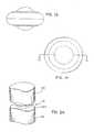
- FIGS. 1A-1Eare directed to various views of one form of an artificial disc implant device in accordance with the present invention showing an enlarged spherical central bearing and an outer annular bearing;
- FIGS. 1F-1H and 1 Jare directed to various views of a disc device slightly modified over that shown in FIGS. 1A-1E to better conform to the vertebrae;
- FIGS. 2A-2Dare directed to various views of the artificial disc device of FIGS. 1A-1E as implanted between adjacent upper and lower vertebrae;
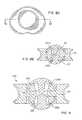
- FIGS. 3A-3Dare directed to various views of an alternative artificial disc in accordance with the present invention showing a pair of dome shells that ride on an inner, spherical bearing portion integral with the outer annular bearing portion;
- FIGS. 4A-4Dare directed to various views of the artificial disc device of FIGS. 3A-3D implanted between upper and lower vertebrae;
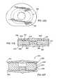
- FIGS. 5A-5Eare directed to various views of an artificial disc device similar to that shown in FIGS. 3A-3D except having a circumferential groove extending about the periphery of the outer bearing portion;
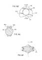
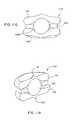
- FIGS. 6A-6Fare directed to various views of another artificial disc device in accordance with the present invention showing a pair of outer, annular bearings that fit about an enlarged, central spherical bearing;
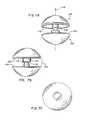
- FIGS. 7A-7Care directed to various views of an alternative construction of the central bearing showing opposing dome shells, one having a central post projection and the other having a central hub;
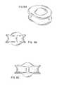
- FIGS. 8A-8Eare directed to various views of an artificial disc device including the dome shells of FIGS. 7A-7C projecting into an opening formed in the inner bearing portion;
- FIG. 9is a cross-sectional view of an alternate form of the artificial disc device of FIGS. 8A-8E showing a pair of inner bearing rings on which the respective dome shells ride with a cushion web wall therebetween.
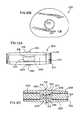
- FIGS. 10A-10Dare directed to various views of another alternative artificial disc device having an axially enlarged central bearing member and an outer, annular bearing member showing an hour-glass configuration for the central-bearing member and an apertured body of the outer bearing member;
- FIGS. 10E-10Hare directed to a modified version of the disc device of FIGS. 10A-10D showing different sizes of through apertures formed in the outer bearing member;
- FIGS. 11A-11Hare directed to various views of alternative artificial disc devices showing upper and lower bearing members and a load bearing member therebetween;
- FIGS. 12A-12Iare directed to various views of an alternative disc device showing upper and lower plate members, and an annular load bearing member and a plug member therebetween.
- an artificial disc device 10which includes an enlarged, central bearing portion 12 , and a substantially annular, outer bearing portion 14 having a through opening 15 in which the central bearing portion 12 is disposed.
- preferred shapes, configurations and material selections for the inner and outer bearing portionsare set forth. However, in each case, these selections are not meant to be limiting as other selections that serve the purpose of the disc implant described herein are also contemplated.
- several embodimentsare disclosed that have structural features that can be implemented substantially interchangeably among the disc implants.
- the central bearing 12has an axially enlarged body 13 relative to the outer bearing 14 so that it generally includes arcuate surface portions 16 and 18 that project above and below the radially outer bearing portion 14 for engaging in indents in confronting surfaces 20 a and 22 a of the adjacent upper and lower vertebrae 20 and 22 , respectively, for seating the implant 10 therein.
- the central bearing 12can be in the form of a generally spherical ball such that the surface portions 16 and 18 are part of the outer spherical surface 24 thereof.
- the annular bearing portion 14has a generally ring-shaped (e.g.
- circular, oval or ellipsoidal body 17that includes an arcuate inner side surface 26 extending about the opening 15 that faces the ball bearing 12 having generally the same radius of curvature as that of the spherical ball surface 24 so that the ball bearing 12 can substantially freely rotate in the small, concave indents, divots or depressions 27 and 29 formed in the vertebrae confronting surfaces in which the ball 12 seats, as described above and shown in FIGS. 2A-2D .
- the vertebral surfaces 20 a and 22 aand particularly the concave indents 27 and 29 formed therein can readily slide over the ball surface 24 .
- the configuration and rotation of the ball bearing 12allows the spine vertebrae 20 and 22 to substantially undergo the normal range of biomechanical movement such as when the patient is twisting their back and/or bending it in various directions.
- the outer bearing 14When the implanted disc 10 undergoes compressive loading, the outer bearing 14 , and in particular the upper and lower surface portions 28 and 30 thereof will substantially maintain the effective spacing between the vertebrae 20 and 22 .
- the outer ring bearing body 17shares the loading with the ball bearing body 13 created between the dynamically moving vertebrae 20 and 22 so as to avoid subsidence problems as occurred with prior ball bearing-type devices. Accordingly, in the disc 10 , the outer bearing 14 generally will not allow the end plates to subside around the ball bearing 12 .
- the curvature of the upper and lower surface portions 28 and 30 of the outer bearing body 17is more gradual than that of the arc surface portions 16 and 18 of the central ball bearing body 13 to provide it with a doughnut-type configuration.
- the surface portions 28 and 30are part of a substantially continuously curved outer ring bearing surface 32 such that they curve around the radially outermost point 29 of the outer bearing body 17 to form an outwardly projecting convex configuration 29 for the outer surface 32 of the annular bearing 14 .
- the surface portions 16 and 18extend to their greatest spacing at the central section 17 a adjacent the central opening 15 of the bearing body 17 .
- the spacing of the surface portions 16 and 18is less than the diameter of the ball bearing 12 so that the surface portions 16 and 18 protrude from the opening 15 to extend above and below the respective outer bearing surface portions 28 and 30 for engaging in the concave depressions 27 and 29 .
- the gradual curvature of the surface portions 28 and 30allows the ring bearing 14 to better conform to the general concavity of the vertebral surfaces 20 a and 22 a including any attached end plates over time.
- the ball bearing diametercan be approximately between 6-18 mm and the maximum thickness of the outer bearing section 17 a can be approximately 16 mm. Manifestly, these sizes are to be tailored according to the anatomy of the patient being treated.
- artificial disc device 10 awhich has a slightly modified wedged or bulged configuration for corresponding outer bearing body 14 ′ thereof. More particularly, as can be seen in the cross-sectional view of FIG. 1J , the outer bearing body 14 ′ has a thickened section 17 a and thinner section 17 b as measured between the corresponding upper and lower surface portions 28 a and 30 a with these sections being generally diametrically opposite each other with a smooth transition therebetween.
- the section 17 a of the disc device 10 awill better conform to the area between the surfaces 20 a and 22 a that are spaced further from each other with the section 17 b fitting better in the more confined, closely spaced area between the vertebrae surfaces 20 a and 22 a allowing the implant device 10 a to be tightly fit or wedged between the vertebrae 20 and 22 .
- the projecting surface portions 16 and 18 of the center ball bearing 12will securely engage in the indented recesses 27 and 29 in the confronting vertebral surfaces 20 a and 22 a for seating the ball bearing 12 therein.
- the present artificial disc device 10resists both migration by the seating of the central ball bearing 12 as well as avoiding subsidence problems by providing load bearing which is well distributed across a large radially extending surface area of the device 10 as by the device upper surfaces 16 and 28 and lower surfaces 18 and 30 .
- the distance from the central axis 19 of the ring bearing 14 extending through the opening 15 to the outer end 29can be approximately 12 mm.
- the inner ball bearing 12preferably will be of a harder material than the outer bearing 14 so that the harder ball 12 is more apt to maintain its conformity with and thus stay seated in the indents 27 and 29 in the surfaces 20 a and 22 a .
- the ball 12can be of a biocompatible material including titanium or metallic material such as stainless steel, while the ring bearing 14 can be of a material of a lower modulus of elasticity such as plastic material, e.g polyethylene, so as to have some resilience under compressive loading forces.
- a support hoop 34 of a harder material than that of the outer bearing 14such as of metal material similar to that of the ball bearing 12 can be embedded therein.
- the hardness of the ball bearing 12 and the hoop 34will both be greater than the outer bearing 14 , although they may not be the same as each other.
- the hoop 34can be of a hard metal material whereas the center bearing 12 can have a hardness similar to the human bone.
- the plastic outer bearing 14can be a molded component of the artificial disc device 10 .
- the metal support hoop 34can be molded in situ in the outer ring bearing 14 .
- the support hoop 34serves as a compression limiter to resist deformation of the resilient plastic ring bearing 14 due to the compressive loading generated between the vertebrae 20 and 22 so that it is better able to maintain its configuration despite the stresses exerted thereon.
- the hoop 34also resists shear forces generated by spinal movements for reducing such forces in the resilient material of the outer bearing 14 .
- outer bearing body 17can have an inner core portion that is of different and softer material than that of the harder outer portion so that the annular bearing 14 has improved shock absorbing properties for high force impacts on the artificial disc 10 with the harder outer layer minimizing wear on the bearing 14 .
- the wear layercan be of hard polyethylene material with the inner cushion material of the bearing body 17 being of a softer polymeric or elastomeric material.
- the body 17can include a hollowed inner portion that is filled with liquid or gel or other elastic material, e.g. Hydrogel and/or polyurethane, for shock absorption purposes.
- FIGS. 3A-3D and 5 A- 5 Eare directed to alternative artificial disc devices 36 and 38 , respectively.
- the disc devices 36 and 38are of similar construction as each include a central bearing portion 39 formed from two opposing shells 40 and 42 having a generally dome-shaped configuration riding on a central or inner, spherical ball bearing portion 44 that can be formed integrally with a body 43 of radially enlarged bearing 46 including outer bearing portion 45 thereof.
- Opposite upper and lower annular arcuate spaces 43 a and 43 bare formed in the body 43 separating the bearing portions 44 and 45 by a distance greater than the thickness of the shells 40 and 42 so that respective shell end portions 47 and 49 fit therein allowing the dome shells 40 and 42 to slide on the ball bearing portion 44 .
- the devices 36 and 38have their bearing portion 45 provided with a pair of lobe sections 48 and 50 that extend in a continuously curved path about the majority of their peripheries until the lobe perimeters meet at their juncture formed at a recessed area 52 therebetween.
- the plan shape of the lobed bearing 46more closely approximates that of the vertebrae 20 and 22 between which the devices 36 and 38 are implanted.
- Ring bearing 14could be provided with a similar lobed plan configuration.
- the outer bearings 14 and 46can be formed with other configuration, e.g. oval in plan, so as to be more closely match that of the intervertebral space in which they are to be implanted.
- load bearing surface portions 54 and 56 of the bearing 46generally corresponding to the load bearing surface portions 28 and 30 of the bearing 14 .
- the surfaces 54 and 56are shown as having a generally flat, parallel configuration so that the bearing body 43 has more of a disc or plate-like configuration.
- some curvature on these bearings surfaces 54 and 56will be desirable although perhaps modified from that shown for bearing surfaces 28 and 30 for the implant 10 .
- the surfaces 54 and 56are provided with a spacing smaller than that of the diameter of the central bearing portion 44 and thus of the central bearing assembly 39 with the dome shells 40 and 42 thereon so that they project above and below the respective surfaces 54 and 56 .
- the dome shells 40 and 42are able to seat in indents 27 and 29 in the vertebral surfaces 20 a and 22 a like the bearing ball surface portion 16 and 18 .
- the shells 40 and 42can be of harder material than that of the bearing body 43 , and particularly the ball bearing portion 44 thereof.
- the dome shells 40 and 42can be of a ceramic material or a stainless-steel metal, titanium or alloys thereof, whereas the ring bearing 46 is preferably of a plastic or polymer material such as polyethylene to provide it with stiffness and resiliency under compressive loading.
- the bearing 46could also be of like material to that of the dome shells 40 and 42 for higher load bearing capacity.
- the dome shells 40 and 42are sized relative to the spherical bearing portion 44 such that there are gap spacings 57 between peripheral end edges 58 and 60 of the respective shells 40 and 42 at their largest diameters and web wall 62 in the bearing 46 , as best seen in the cross sectional views of FIGS. 3D and 5D . Accordingly, the diameter across the end edges 58 and 60 of the dome shells is less than the diameter of the ball bearing portion 44 . In use, the dome shells 40 and 42 can slide to take up these spaces 57 .
- the web wall 62extends laterally or radially and centrally from the ball bearing portion 44 to the annular load bearing portion 45 that extends about the ball bearing portion 44 on which the shells 40 and 42 ride.
- the circumferential web wall 62extends radially for a sufficient distance, such that the outer bearing portion 45 is spaced from the ball bearing portion 44 to provide recesses 43 a and 43 b large enough to allow the dome edges 58 and 60 to slide into engagement with the web wall 62 without encountering interference from the annular load bearing portion 45 of the bearing 46 .
- the annular bearing portion 45includes a radially inner surface 51 that extends generally axially or tangentially to outer spherical surface 44 a of the inner bearing portion 44 , albeit spaced slightly therefrom via web wall 62 .
- the corresponding spaces 43 a and 43 b in the body 43 of the device 38are enlarged over those in device 36 such that overhanging portions of the bearing portion 45 that can be compressed against the dome shell portions 47 and 49 and potentially cause binding in the spaces 43 a and 43 b are avoided.
- the artificial disc devices 36 and 38have a bi-polar construction in that relative movement between the vertebrae 20 and 22 and the dome shells 40 and 42 can occur along with relative movement between the dome shells 40 and 42 and the ball bearing portion 44 .
- the smooth surface interface between inner surfaces 40 a and 42 a of the respective shells 40 and 42 and the outer surface 44 a of the ball bearing portion 44will have a lower coefficient of friction therebetween than that between outer surfaces 40 b and 42 b of the respective shells 40 and 42 and the indents 27 and 29 in the vertebrae surfaces 20 a and 22 a .
- FIGS. 4A-4Dillustrate the lobed artificial disc device 36 implanted between the adjacent upper and lower vertebrae 20 and 22 .
- the disc device 36is employed with the annulus 65 kept intact, and in the other view, the annulus 65 is removed with the disc device 36 implanted.
- the disc device 36is inserted through an incision in the annulus 65 which may be repaired once the device 36 is implanted. In this instance, the device 36 reinflates the annulus 65 keeping it taut and relieves the compressive loading on the annulus 65 .
- the other artificial disc devices described hereincan be employed in a like manner to that of device 36 .
- the annular load bearing body portion 45 of the device 36has an outer peripheral surface 66 ( FIG. 3C ) with a generally convex configuration similar to the convex curved configuration at the corresponding radially outer location of the outer annular bearing 14 .
- the corresponding surface 68 of the load bearing portion 46 of the device 38 shown in FIG. 5Chas a grooved or concave configuration to form thinned upper and lower flange rims 70 and 72 thereof.
- the above-described construction for the bearing 46 as shown in FIG. 5Cprovides it with greater flexibility as the flanges 70 and 72 are better able to flex toward each other under compressive loading and thus are optimized from a shock absorption standpoint.
- upper and lower annular layers including the flanges 70 and 72can be provided of harder material than a more flexible core material of the bearing body 43 for optimized wear resistance at the interfaces with the vertebral surfaces 20 a and 22 a and also for improved shock absorbing properties for the device 38 a .
- the wear layerscan be of hard polyethylene while the core of the body 43 would be of more flexible, e.g. elastomeric, cushioning material.
- FIGS. 6A-6Fanother artificial disc device 74 in accordance with the invention is illustrated.
- the artificial disc device 74is similar to the device 10 of FIGS. 1A-1E in that it includes a central ball bearing 76 such as of ceramic material or stainless steel or titanium metal and alloys thereof or having carbon fiber or other biocompatible materials therein and including projecting arc surface portions 78 and 80 for seating in the indents 27 and 29 in the vertebral surfaces 20 a and 22 a , as previously described.
- a central ball bearing 76such as of ceramic material or stainless steel or titanium metal and alloys thereof or having carbon fiber or other biocompatible materials therein and including projecting arc surface portions 78 and 80 for seating in the indents 27 and 29 in the vertebral surfaces 20 a and 22 a , as previously described.
- the device 74is modified over device 10 in that rather than having a doughnut shaped bearing 14 , the device 74 includes a pair of annular plates or discs 82 and 84 such as of a metallic material vertically spaced along central axis 86 that extends through the central openings 88 and 90 formed in the respective discs 82 and 84 in which the ball bearing 76 is received.
- the disc openings 88 and 90are of a maximum diameter that is slightly less than that of the diameter of the ball bearing 76 such that when the arcuate surfaces 83 and 85 about the openings 88 and 90 are in close fit with the outer ball surface 92 and the discs 82 and 84 are in a generally parallel orientation, the discs 82 and 84 will be spaced by a gap 94 therebetween.
- the device 74With the device 74 loaded and the confronting vertebral surfaces 20 a and 22 a engaging and pushing on the discs 82 and 84 , they will shift and pivot relative to each other and axis 86 closing the gap 94 at certain locations thereabout and opening it at others.
- the upper surface 82 a and lower surface 84 a of the respective upper and lower discs 82 and 84that are the major load bearing surfaces for the device 74 .
- these surfaces 82 a and 84 acan be contoured so that the respective discs become thicker as extending from the periphery toward the respective openings 88 and 90 of the discs 82 and 84 .
- a resilient and flexible cushioning material 95can be attached between the discs 82 and 84 .
- the material 95will keep the unloaded discs 82 and 84 in the illustrated, generally parallel orientation, but also allow them to undergo relative shifting under compressive loading.
- the material 95is selected so that it can resiliently expand and contract as the discs 82 and 84 shift and tilt or pivot with respect to each other.
- the unloaded discs 82 and 84could be canted to a non-parallel orientation relative to each other to provide the disc device 74 with a wedged configuration similar to the previously-described device 10 a.
- the spine and particularly the vertebrae 20 and 22exert compressive loading on the discs 82 and 84 , they can shift relative to one another so they are better able to conform to the position of the vertebrae 20 and 22 as they shift with spine movement.
- the upper disc 82can tilt relative to the axis 86 so the gap spacing 94 between the discs 82 and 84 can be greater at the rear portion than at the forward portions thereof.
- the upper disc 82can pivot about axis 86 such that the gap spacing 94 can be greater at the forward portions relative to the spacing at the rear portions.
- the discs 82 and 84can have a plan configuration akin to that of the lobed bearing 46 , or alternatively they can be oval or ellipsoidal. As shown in the plan view of FIG. 6D , the configuration of the discs 82 and 84 includes a larger recessed or concave area 94 as compared with the corresponding recess area 52 of the ring bearing 46 . Further, the curvature of the remainder of the disc periphery 96 varies from a convexly curved portion 98 opposite the recessed area 94 to straighter opposite sides 100 and 102 on either side of the recessed area 94 .
- FIGS. 7A-7Can alternative construction for the central bearing 39 is shown.
- a pair of opposing domes 104 and 106are provided which ride on an inner bearing portion 107 similar to previously-described ball bearing portion 44 , albeit modified to accommodate the projecting post 108 and hub 110 , which are described below.
- the hub 110can have a recess 112 which can engage against the distal curved end 114 of the post 108 to resist the compressive forces that otherwise would push the dome shells 104 and 106 further toward each other. More particularly, the dome shell 104 has an end edge 116 and the post 108 extends centrally from the shell 104 along axis 118 so that it projects beyond the edge 116 . Likewise, the shell 106 includes an end edge 120 beyond which the hub 110 can project along the central axis 118 so that it is in alignment with the post 108 .
- the post 108 and hub 110have their respective sizes coordinated so that they define a limit at which spacing 122 between the dome shells 104 and 106 cannot be exceeded with the end edges 116 and 120 extending generally parallel to each other.
- the dome shells 104 and 106which are preferably of a harder material such as metal employ the cooperating integral post 108 and hub 110 for limiting the maximum compression that can occur therebetween.
- the post 108 and hub 110will be spaced or only lightly engaged so that they do not bear the loads generated between the vertebrae 20 and 22 .
- the central or inner bearing portion 107is modified so that the post 108 and hub 110 can project therethrough.
- the bearing portion 107has an axial through opening 124 having reversely configured upper and lower frustoconical surface portions 124 a and 124 b into which the post 108 and hub 110 extend, respectively.
- the surface portions 124 a and 124 btaper from the largest size of the opening 124 at the dome surfaces to the smallest size of the opening 124 at the center of the ball bearing portion 107 .
- Thisprovides the domes 104 and 106 with freedom of movement about the ball bearing portion 107 allowing the post 108 and hub 110 to rock back and forth until the dome ends 116 and 120 engage the web wall 62 without encountering interference from the surface portions 124 a and 124 b , respectively.
- FIG. 9a further variation of the central bearing assembly shown in FIGS. 8A-8E is illustrated.
- upper and lower inner bearing rings 126 and 128are provided supported by an inner extension 130 of the web wall 62 that extends therebetween.
- the rings 126 and 128each have an outer arcuate bearing surface 126 a and 128 a on which the dome shells 104 and 106 ride.
- the rings 126 and 128can also translate along the web wall 62 to provide for lateral movement of either or both dome shells 104 and 106 during articulation of the spine such as when the patient bends their spine in flexion or extension.
- the device 125provides for an even greater range of motion than the previously described devices as there are now three shifting interfaces including the innermost interface between the rings 126 and 128 and web wall 62 enabling the dome shells 104 and 106 to reciprocate therealong.
- the shells 104 and 106may be rotating in the indents 27 and 29 and rotating about the rings surfaces 126 a and 128 a , such as in the previously-described devices.
- the rings 126 and 128can be of a hard polyethylene material while the web wall 62 is preferably of a more flexible or pliant material for shock absorption purposes.
- the rings 126 and 128 on the web wall 62can be coated with a harder material or have washers of metallic or a like hardness material attached to upper and lower surfaces thereof to reduce the friction coefficient with the rings 126 and 128 sliding thereon.
- FIGS. 10A-10Han alternative artificial disc implant device 132 is illustrated in which there is an enlarged, central bearing member 134 and an outer bearing member 136 which share the compressive loads generated between the vertebrae 20 and 22 during typical spine movements.
- the central bearing member 134has a post body 138 that is axially elongated such that upper and lower arcuate bearing surfaces 140 and 142 generally extend beyond corresponding upper and lower bearing surfaces 144 and 146 formed on annular body 148 of the outer bearing member 136 , similar to the previously-described disc implants herein.
- the outer bearing body 148has a central through opening 150 that is bounded by a cylindrical inner surface 152 in close confronting relation to outer side surface 154 on the post body 138 .
- through apertures 156can be formed at selected locations extending axially therethrough, as shown in FIG. 10 D. These apertures 156 provide an increase in the normal compressibility or coefficient of restitution of the material, e.g. plastic, of the bearing body 148 . Based on the position, pattern and/or density of the through apertures 156 , the flexibility or compressibility of the body 148 can be increased or decreased in a localized fashion.
- apertures 156could be employed in the other disc implants and specifically the bodies of the outer bearings thereof in a like fashion.
- the previously-described liquid or gel material, e.g. Hydrogel, used in the outer bearing body 17could also be provided in the apertures 156 so that they do not extend all the way through the body 138 and instead serve as chambers for the visco-elastic material therein to vary compressibility of the body 148 .
- the frequency of the apertures 156can be increased in a radially outward direction from the central opening 150 to the periphery of the bearing body 148 so that in a like fashion the body 148 can be more easily compressed toward the periphery thereof.
- the size or diameter of the holes 156can vary such as by having, for example, smaller size apertures 156 a closer to the central opening 150 , larger size apertures 156 b closest to the radially outer periphery of the body 148 , with apertures 156 c having sizes intermediate those of apertures 156 a and 156 b generally disposed therebetween, as shown in FIG. 10 E.
- the bearing body 148can be made to be more or less flexibly resilient at precise locations thereabout. In this manner, the bearing body 148 can be stiffer in locations where load bearing is more critical and more compressible at positions were shock absorption is more important. It is also anticipated that the apertures 156 will provide stress relief for the load bearing body 148 so as to increase the life thereof.
- the post body 138preferably is provided with a recess in its surface 154 such as annular groove 139 formed approximately midway along the body length between the bearing surfaces 140 and 142 thereof.
- a recess in its surface 154such as annular groove 139 formed approximately midway along the body length between the bearing surfaces 140 and 142 thereof.
- this groove 139there is a gap 155 that is formed between the confronting bearing surfaces 152 and 154 .
- FIGS. 11A-11DAn alternative disc device 175 is shown in FIGS. 11A-11D having upper and lower disc plate members 176 and 178 with there being a load bearing member 180 therebetween.
- the device 175like other devices described herein allows for relative movement between the vertebrae 20 and 22 and the respective vertebral engaging members 176 and 178 .
- the plate members 176 and 178have arcuate vertebral engaging surfaces 182 and 184 formed thereon having a gradual curvature or slope extending from the outer periphery up toward central axis 186 of the device 175 . As the surfaces 182 and 184 approach the axis 186 they begin to extend more axially than radially to form center projections 188 and 190 .
- projections 188 and 190are shown in FIGS. 11C and 11D as being provided with a tip or point end 191 and 193 for piercing into the vertebral bone locating the device 175 implanted between the vertebrae 20 and 22 although they also could simply be curved or sloped as shown in FIGS. 11A and 11B to serve the same locating function similar to the center arcuate surface portions of previously-described devices.
- the surfaces 182 and 184include radially extending bearing surface portions 182 a and 184 a that extend radially along the respective facing vertebral surfaces and central, axially extending bearings surface portions 182 b and 184 b that serve to locate the device 175 while also allowing relative sliding rotation of the vertebrae 20 and 22 thereabout and specifically 360° about device axis 186 since the plate members 176 and 178 are not fixed to the respective vertebrae 20 and 22 .
- the center surface portion 182 b and 184 bonly resist lateral sliding of the plates 176 and 178 by fitting in correspondingly shaped recesses or openings in the vertebral facing surfaces 20 and 22 a and otherwise are not fixed or fastened thereto.
- the member 180has a spherical ball configuration.
- the plates 176 and 178have arcuate recessed surfaces 192 and 194 opposite their surfaces 182 and 184 and in which the ball member 180 seats.
- the ball member 180can be of a harder material, e.g. steel, than the softer disc plate members 176 and 178 .
- the materials for the members 176 - 180is preferably selected for low frictional resistance to relative sliding movement therebetween to allow rotation of the members 176 - 180 such as when the spine is twisted and to allow relative sliding between the plate members 176 and 178 and ball 180 such as when the spine is bent in flexion and extension with the plates 176 and 178 pivoting with respect to each other.
- the device 175is bi-polar since there are two shifting interfaces thereof, i.e. between the plates 176 and 178 and the vertebrae 20 and 22 and between the ball 180 and the plates 176 and 178 .
- FIGS. 11E-11Hare views of another device 175 ′ similarly constructed to device 175 including upper and lower plates 176 and 178 with a ball bearing 180 therebetween.
- the device 175 ′also includes an annular member 196 that extends about the ball bearing 180 with the plates 176 and 178 engaged against upper and lower surfaces 196 a and 196 b thereof.
- the annular member 196acts as a shock absorber and can be formed of an elastomeric or other resilient material.
- the various forms of artificial disc devices disclosed hereinrely on both a center bearing portion and an outer, annular bearing portion extending about the center bearing portion to provide implants that resist migration without relying on disc fixing mechanisms such as intrusive bone fasteners, clamps and the like while also avoiding subsidence problems about the center bearing portion.
- the upper and lower arcuate surfaces of the center bearing or bearing portion or bearing assemblyseat in correspondingly shaped recesses 27 and 29 in the vertebral surfaces 20 a and 22 a to locate the artificial disc device between the vertebrae 20 and 22 .
- the interface between the center bearing surface portions and the recesses 27 and 29is preferably a sliding one, i.e.
- the convex curvature of the center surface portions seated in the concave recessesprovides resistance against migration or lateral shifting of the device out from between the vertebrae.
- outer bearing surface portionsthat also extend radially outwardly therefrom, generally with a more gradual curvature or with a flat configuration.
- the outer bearing surface portionsextend so that their radial outer ends are close to the periphery of the respective vertebral bodies thereabove and therebelow.
- the upper outer bearing surface portionis generally lower than the axially projecting upper center bearing surface portion, and they form a juncture at which the direction in which the surface portions of the disc device for engaging the vertebrae changes or transitions from one extending more axially to one extending more radially.
- This junctureis a direction transition area and does not necessarily mean that the surface portions are joined thereat, such as can be seen with the previously-described ball bearing 12 and ring bearing 14 which are separate components with the ring bearing 14 extending annularly around the ball bearing 12 so as to allow for relative movement therebetween.
- the lower outer bearing surface portionis generally higher than the axially projecting lower center bearing surface portion, and at their juncture the direction of the vertebral engagement surface portion of the device also changes as described above with respect to the upper vertebral engagement surface portions. In this manner, these radially extending outer surface portions limit the ability of the vertebrae or their attached end plates to subside around the center bearing.
- the spacing of the upper and lower vertebraecan not be less than the spacing between the outer bearing surface portions, thereby limiting subsidence problems accordingly.
- upper and lower arcuate center bearing surface portions 202 and 204that are convexly curved are provided for locating the device 200 between adjacent vertebrae in corresponding arcuate concave recesses formed therein.
- Upper and lower outer bearing surface portions 206 and 208extend annularly about respective center bearing surface portions 202 and 204 and limit subsidence between the vertebrae about the center bearing portion 210 of the device 200 .
- the upper surface portions 202 and 206are formed integrally on an upper plate member 212
- the lower surface portions 204 and 208are formed integrally on a lower plate member 214 .
- the plate members 212 and 214can be of a hard biocompatible material such as titanium coated with a pyroletic carbon.
- the center bearing surface portions 202 and 204are spaced by an axially greater distance than the outer bearing surface portions 206 and 208 , and they have a smaller radius of curvature than the more gradual curvature of the surface portions 206 and 208 .
- the plate members 212 and 214include respective small, axial projections 213 and 215 that are centrally disposed relative to disc axis 216 and on which the respective center bearing surface portions 202 and 204 are formed.
- annular load bearing portion or member 224is provided axially between the upper and lower bearing plates 212 and 214 .
- the member 224is preferably of a resilient material such as an elastomeric or resiliently compressible polymeric material, e.g. polyurethane and silicone combination, or a hydrogel material, for taking loads that are generated between the vertebrae during normal spinal movements.
- the annular member 224has an axial thickness sized to maintain the plates 212 and 214 spaced axially by an anatomically correct distance from each other for engaging the vertebrae and keeping them properly spaced.
- the resilient material of the load bearing member 224allows the plates 212 and 214 to shift or deflect relative to each other during dynamic relative movements of the spine vertebrae 20 and 22 such as when the spine is being twisted and bent as in flexion or extension movements.
- the plates 212 and 214may be pivoting toward each other compressing the member 224 therebetween while at a generally diametrically opposite end the plates 212 and 214 will pivot or shift away from each other allowing for expansion of the resilient material of the member 224 in this area between the plates 212 and 214 .
- the annular bearing member 224can be a composite to include a harder low friction wear coating on its upper and lower surfaces to allow the facing lower and upper surfaces of the respective upper and lower bearing plates 212 and 214 to minimize wear in this interface area such as when compressional and/or torsional forces are applied therebetween.
- upper and lower annular washers or wear plates 226 and 228can be inserted in the interfaces between the upper bearing plate 212 and the load bearing member 224 and the lower bearing plate 214 and the load bearing member 224 to allow the plates 212 and 214 to have a low friction surface in engagement therewith.
- the annular configuration of the load bearing member 224 of the outer bearing portion 222forms an interior central space 230 in which a bumper or plug member 232 is provided as part of the center bearing portion 210 of the device 200 .
- the bumper member 232fits somewhat loosely in the interior space 230 and is of a harder material having a higher modulus of elasticity than the outer bearing member 224 .
- the plug member 232is operable during high impact loading on the vertebrae to keep the annular member 224 from deforming too much and overloading. In normal loading conditions, there is a spacing between the upper plate member 212 and the bumper member 232 .
- the harder plug member 232allows the annular member 224 to be softer so that its cushioning function between the vertebrae can be maximized.
- the material of the member 224needs to be of sufficient stiffness or resiliency so as to be substantially shape retentive for maintaining stability between the vertebrae over millions of cycles and without experiencing undesirable material creep or plastic deformation due to the heavy loading it will undergo.
- the plates 212 and 214have respective arcuate projections 234 and 236 that extend toward each other in the interior space 230 .
- the plug member 232has upper and lower arcuate recesses 238 and 240 concavely configured to mate with the convex configuration of the arcuate projections 234 and 236 , respectively.
- the relative sizing of the space 230 and the plug member 232 thereinis such that when the plug member 232 rests on the lower plate 214 via seating of the projection 236 in the recess 240 , there will be an axial gap 242 between the plug 232 and the upper plate 212 and specifically the respective surface 238 and projection 234 thereof.
- the annular member 224has a greater axial thickness than the plug member 232 .
- the space 230has a larger diameter than the plug member 232 so that there is a generally lateral space between the inner surface 224 a of the annular member 224 and the plug member 232 allowing for lateral deformation of the resilient member 224 when loaded.
- the normal loading ring member 224is compressed taking up the axial gap 242 such that the projection 234 engages the harder plug member 232 in the recess 238 thereof. In this manner, further compression and overloading of the resilient member 224 is avoided.
- engagement of the projections 234 and 236 in their recesses 238 and 240resists relative lateral shifting between the plates 212 and 214 , and the annular member 222 .
- annular member 224 and plug member 232could be integrally formed with one another, although having the members 224 and 232 as separate components is the preferred form for the present disc device 200 .
- the arcuate projections 234 and 236are larger than the respective arcuate surface portions 202 and 204 .
- the projections 234 and 236are centrally disposed relative to axis 216 and extend radially for a greater distance on either side of axis 216 than do the arcuate surface portions 202 and 204 so that there is a greater bearing surface interface between the plate projections 234 and 236 and the plug member 232 than between the locating surface portions 202 and 204 and the vertebrae.
- the plug member 232when the plug member 232 is loaded, it provides relatively large bearing surfaces for the plates 212 and 214 , and also allows for pivoting between the plates 212 and 214 with the plate central projections 234 and 236 sliding in respective recesses 238 and 240 and with compression and expansion of generally diametrically opposed portions of the member 224 depending on the exact location of the loads placed on the device 200 .
- the surface portions 202 and 204can be similarly sized to the projections 234 and 236 or even larger for maximizing the bearing surface area they provide between the device and the vertebrae.
- the disc device 200is shown with modifications including an annular sheath 244 that extends about the outer periphery of the device 200 .
- the sheath 244includes upper and lower lips 246 and 248 and that grip around and onto the upper and lower surfaces 206 and 208 , respectively, of the outer bearing assembly 222 to hold the device 200 in its assembled form for implantation.
- a bag completely encasing the device 200could be employed.
- a retaining structurecan be provided between the plates 212 and 214 and the annular member 224 for resisting relative lateral shifting between the plates 212 and 214 , and the member 222 , as well as resisting relative rotational shifting therebetween for keeping these disc components aligned.
- Projecting posts 252 and 254can project down from the underside of the upper plate 212
- posts 256 and 258can project up from the upper side of the lower plate 214 .
- Corresponding aperture pairs 260 and 262can be formed in the upper and lower surfaces of the annular bearing member 224 for receiving the respective post pairs 252 , 254 and 256 , 258 therein, as can be seen in FIG. 12 E.
- upper and lower annular grooves 261can be formed in upper and lower surfaces of the annular bearing member 224 for receipt of corresponding upper and lower raised ridges formed on the resilient annular member 224 . Since the plan shape or configuration of the plates 212 and 214 and member 224 are other than circular, it is desirable for the ridges and grooves to be similarly configured so that relative rotational sliding as well as translational or lateral sliding between these components is resisted. Again, the components on which the cooperating grooves and ridges are formed can be reversed from that described above.
- the structure 250can be provided at the periphery of the device 200 , as shown in FIG. 12 F.
- the upper plate 212includes a downwardly extending peripheral lip projection 263
- the lower plate 214includes an upwardly extending peripheral lip projection 264 .
- the resilient member 224is provided with peripheral grooves 266 and 268 in which the lips 262 and 264 extend so as to restrain the member 224 against lateral and rotational shifting relative to the plates 212 and 214 .
- FIGS. 12G-12Ishow device 200 modified to include upper and lower recessed channels 270 formed in the upper and lower surfaces of the annular member 224 that extend from the inner, axially extending surface 224 a to the outer peripheral surface 224 b of the member 224 to form openings at each surface.
- the interior space 230 in which the plug member 232 is receivedcommunicates with the space external to the device 200 via the flowpaths provided by the channels 270 .
- the channels 270allow for fluid flow into and out from the device between the plates 212 and 214 and the annular member 224 .
- the channels 270also keep vacuum conditions from developing in the space 230 as its volume continually varies with vertebral movements and thus the channels 270 serve as a vacuum breaker for the device 200 .
- the channels 270can be provided in a radial pattern so that there are several pairs of channels 270 extending in radially opposite directions from the center space 230 , as best seen in FIG. 12 H.
Landscapes
- Health & Medical Sciences (AREA)
- Engineering & Computer Science (AREA)
- Biomedical Technology (AREA)
- Neurology (AREA)
- Orthopedic Medicine & Surgery (AREA)
- Cardiology (AREA)
- Oral & Maxillofacial Surgery (AREA)
- Transplantation (AREA)
- Heart & Thoracic Surgery (AREA)
- Vascular Medicine (AREA)
- Life Sciences & Earth Sciences (AREA)
- Animal Behavior & Ethology (AREA)
- General Health & Medical Sciences (AREA)
- Public Health (AREA)
- Veterinary Medicine (AREA)
- Prostheses (AREA)
Abstract
Description
Claims (11)
Priority Applications (10)
| Application Number | Priority Date | Filing Date | Title |
|---|---|---|---|
| US10/282,620US7001433B2 (en) | 2002-05-23 | 2002-10-29 | Artificial intervertebral disc device |
| CNA038169894ACN1668259A (en) | 2002-05-23 | 2003-05-23 | Artificial Disc Device |
| AU2003245321AAU2003245321A1 (en) | 2002-05-23 | 2003-05-23 | Artificial intervertebral disc device |
| JP2004506700AJP2005527296A (en) | 2002-05-23 | 2003-05-23 | Artificial intervertebral disc device |
| EP03738960AEP1513475A4 (en) | 2002-05-23 | 2003-05-23 | Artificial intervertebral disc device |
| PCT/US2003/016394WO2003099172A1 (en) | 2002-05-23 | 2003-05-23 | Artificial intervertebral disc device |
| US10/692,468US8388684B2 (en) | 2002-05-23 | 2003-10-22 | Artificial disc device |
| US10/971,734US8241360B2 (en) | 2002-05-23 | 2004-10-22 | Artificial disc device |
| US11/184,625US8262731B2 (en) | 2002-05-23 | 2005-07-19 | Artificial disc device |
| US13/585,607US9351852B2 (en) | 2002-05-23 | 2012-08-14 | Artificial disc device |
Applications Claiming Priority (2)
| Application Number | Priority Date | Filing Date | Title |
|---|---|---|---|
| US38275802P | 2002-05-23 | 2002-05-23 | |
| US10/282,620US7001433B2 (en) | 2002-05-23 | 2002-10-29 | Artificial intervertebral disc device |
Related Parent Applications (1)
| Application Number | Title | Priority Date | Filing Date |
|---|---|---|---|
| US10/692,468Continuation-In-PartUS8388684B2 (en) | 2002-05-23 | 2003-10-22 | Artificial disc device |
Related Child Applications (3)
| Application Number | Title | Priority Date | Filing Date |
|---|---|---|---|
| US10/692,468Continuation-In-PartUS8388684B2 (en) | 2002-05-23 | 2003-10-22 | Artificial disc device |
| US10/971,734Continuation-In-PartUS8241360B2 (en) | 2002-05-23 | 2004-10-22 | Artificial disc device |
| US11/184,625ContinuationUS8262731B2 (en) | 2002-05-23 | 2005-07-19 | Artificial disc device |
Publications (2)
| Publication Number | Publication Date |
|---|---|
| US20030220691A1 US20030220691A1 (en) | 2003-11-27 |
| US7001433B2true US7001433B2 (en) | 2006-02-21 |
Family
ID=29552964
Family Applications (2)
| Application Number | Title | Priority Date | Filing Date |
|---|---|---|---|
| US10/282,620Expired - Fee RelatedUS7001433B2 (en) | 2002-05-23 | 2002-10-29 | Artificial intervertebral disc device |
| US11/184,625Expired - Fee RelatedUS8262731B2 (en) | 2002-05-23 | 2005-07-19 | Artificial disc device |
Family Applications After (1)
| Application Number | Title | Priority Date | Filing Date |
|---|---|---|---|
| US11/184,625Expired - Fee RelatedUS8262731B2 (en) | 2002-05-23 | 2005-07-19 | Artificial disc device |
Country Status (6)
| Country | Link |
|---|---|
| US (2) | US7001433B2 (en) |
| EP (1) | EP1513475A4 (en) |
| JP (1) | JP2005527296A (en) |
| CN (1) | CN1668259A (en) |
| AU (1) | AU2003245321A1 (en) |
| WO (1) | WO2003099172A1 (en) |
Cited By (52)
| Publication number | Priority date | Publication date | Assignee | Title |
|---|---|---|---|---|
| US20050187632A1 (en)* | 2004-02-20 | 2005-08-25 | Rafail Zubok | Artificial intervertebral disc having a bored semispherical bearing with a compression locking post and retaining caps |
| US20050192671A1 (en)* | 2002-05-23 | 2005-09-01 | Pioneer Laboratories, Inc. | Artificial disc device |
| US20050256581A1 (en)* | 2002-05-23 | 2005-11-17 | Pioneer Laboratories, Inc. | Artificial disc device |
| US20060136061A1 (en)* | 2003-04-04 | 2006-06-22 | Theken Disc, Llc | Artificial disc prosthesis |
| US20060224240A1 (en)* | 2005-04-04 | 2006-10-05 | Sdgi Holdings, Inc. | Non-circular stabilization sphere and method |
| US20060229725A1 (en)* | 2003-07-22 | 2006-10-12 | Beat Lechmann | Intervertebral implant comprising dome-shaped joint surfaces |
| US20060235531A1 (en)* | 2004-10-18 | 2006-10-19 | Karin Buettner-Janz | Intervertebral disc prosthesis with transversally arched, curved cylindrical articulation surfaces for the lumbar and cervical spine |
| US20070088441A1 (en)* | 2004-06-30 | 2007-04-19 | Synergy Disc Replacement, Inc. | Artificial Spinal Disc |
| US20070100453A1 (en)* | 2005-10-31 | 2007-05-03 | Depuy Spine, Inc. | Intervertebral disc prosthesis |
| US20070203580A1 (en)* | 2006-02-24 | 2007-08-30 | Paonan Biotech Co., Ltd. | Intervertebral filling |
| US20070270970A1 (en)* | 2006-03-14 | 2007-11-22 | Sdgi Holdings, Inc. | Spinal implants with improved wear resistance |
| US20080109081A1 (en)* | 2003-10-22 | 2008-05-08 | Qi-Bin Bao | Joint Arthroplasty Devices Having Articulating Members |
| US20080114453A1 (en)* | 2006-11-13 | 2008-05-15 | Warsaw Orthopedic, Inc. | Intervertebral prosthetic devices and surgical methods |
| US20080133013A1 (en)* | 2004-06-30 | 2008-06-05 | Synergy Disc Replacement, Inc. | Artificial Spinal Disc |
| US20080154380A1 (en)* | 2000-01-30 | 2008-06-26 | Dixon Richard H | Articulating diamond-surfaced spinal implants |
| US20080215156A1 (en)* | 2004-06-30 | 2008-09-04 | Synergy Disc Replacement | Joint Prostheses |
| US20090069897A1 (en)* | 2007-09-12 | 2009-03-12 | Butler Michael S | Spinal Interbody Device |
| US20090076616A1 (en)* | 2004-06-30 | 2009-03-19 | Synergy Disc | Systems and Methods for Vertebral Disc Replacement |
| US20090248161A1 (en)* | 2008-03-20 | 2009-10-01 | K2M, Inc. | Artificial disc replacement device |
| US20100016970A1 (en)* | 2008-07-17 | 2010-01-21 | John Kapitan | Spinal interbody spacers |
| US20100100185A1 (en)* | 2008-10-22 | 2010-04-22 | Warsaw Orthopedic, Inc. | Intervertebral Disc Prosthesis Having Viscoelastic Properties |
| US20100161064A1 (en)* | 2006-11-07 | 2010-06-24 | Kellar Franz W | Prosthetic joint |
| US20100185288A1 (en)* | 2009-01-21 | 2010-07-22 | Warsaw Orthopedic, Inc | Spinal nucleus replacement implant |
| US20100228350A1 (en)* | 2009-03-04 | 2010-09-09 | Warsaw Orthopedic, Inc. | Spinal nucleus replacement implants |
| US20100262250A1 (en)* | 2006-11-07 | 2010-10-14 | Kellar Franz W | Prosthetic ball-and-socket joint |
| US20100312348A1 (en)* | 2009-06-04 | 2010-12-09 | Howmedica Osteonics Corp. | Orthopedic paek-on-polymer bearings |
| US20100324688A1 (en)* | 2009-06-18 | 2010-12-23 | Mekatronix | Intervertebral spinal disc prosthesis |
| US20110035010A1 (en)* | 2009-08-07 | 2011-02-10 | Ebi, Llc | Toroid-shaped spinal disc |
| US20110035006A1 (en)* | 2009-08-07 | 2011-02-10 | Ebi, Llc | Toroid-Shaped Spinal Disc |
| US20110071636A1 (en)* | 2009-09-18 | 2011-03-24 | National Yang Ming University | Displacement Leaf Spring and Artificial Intervertebral Disc Containing the Same |
| US20110118845A1 (en)* | 2008-07-14 | 2011-05-19 | Synthes Usa, Llc | Flexible dampening intervertebral spacer device |
| US20110230912A1 (en)* | 2010-03-18 | 2011-09-22 | Dennis M David | Cortical, anti-migration, facet dowel for fusion of facet joints in the spine and devices for setting the same in place |
| US20110238185A1 (en)* | 2004-05-18 | 2011-09-29 | Zimmer Gmbh | Intervertebral disk implant |
| US8029574B2 (en) | 2006-11-07 | 2011-10-04 | Biomedflex Llc | Prosthetic knee joint |
| US8070823B2 (en) | 2006-11-07 | 2011-12-06 | Biomedflex Llc | Prosthetic ball-and-socket joint |
| US8163023B2 (en) | 2007-02-09 | 2012-04-24 | Diamicron, Inc. | Multi-lobe artificial spine joint |
| US8277505B1 (en) | 2011-06-10 | 2012-10-02 | Doty Keith L | Devices for providing up to six-degrees of motion having kinematically-linked components and methods of use |
| US8287598B1 (en) | 2011-12-05 | 2012-10-16 | TrueMotion Spine, Inc. | True spinal motion preserving, shock absorbing, intervertebral spinal disc prosthesis |
| US8308812B2 (en) | 2006-11-07 | 2012-11-13 | Biomedflex, Llc | Prosthetic joint assembly and joint member therefor |
| US8512413B2 (en) | 2006-11-07 | 2013-08-20 | Biomedflex, Llc | Prosthetic knee joint |
| US9005306B2 (en) | 2006-11-07 | 2015-04-14 | Biomedflex, Llc | Medical Implants With Compliant Wear-Resistant Surfaces |
| US9005307B2 (en) | 2006-11-07 | 2015-04-14 | Biomedflex, Llc | Prosthetic ball-and-socket joint |
| US9011538B2 (en) | 2009-01-21 | 2015-04-21 | Warsaw Orthopedic, Inc. | Methods of spinal nucleus replacemennt |
| US20150245916A1 (en)* | 2013-03-14 | 2015-09-03 | Brian D. Burkinshaw | Unitary Spinal Disc Implant |
| US9233011B2 (en) | 2006-09-15 | 2016-01-12 | Pioneer Surgical Technology, Inc. | Systems and apparatuses for inserting an implant in intervertebral space |
| US9241807B2 (en) | 2011-12-23 | 2016-01-26 | Pioneer Surgical Technology, Inc. | Systems and methods for inserting a spinal device |
| US9566157B2 (en) | 2006-11-07 | 2017-02-14 | Biomedflex, Llc | Three-member prosthetic joint |
| US9700425B1 (en) | 2011-03-20 | 2017-07-11 | Nuvasive, Inc. | Vertebral body replacement and insertion methods |
| USD899597S1 (en) | 2014-02-10 | 2020-10-20 | Brian D. Burkinshaw | Unitary spinal disc implant with at least one conic protrusion |
| USD907771S1 (en) | 2017-10-09 | 2021-01-12 | Pioneer Surgical Technology, Inc. | Intervertebral implant |
| US11147682B2 (en) | 2017-09-08 | 2021-10-19 | Pioneer Surgical Technology, Inc. | Intervertebral implants, instruments, and methods |
| US11452618B2 (en) | 2019-09-23 | 2022-09-27 | Dimicron, Inc | Spinal artificial disc removal tool |
Families Citing this family (98)
| Publication number | Priority date | Publication date | Assignee | Title |
|---|---|---|---|---|
| FR2824261B1 (en) | 2001-05-04 | 2004-05-28 | Ldr Medical | INTERVERTEBRAL DISC PROSTHESIS AND IMPLEMENTATION METHOD AND TOOLS |
| US20060129242A1 (en)* | 2001-12-28 | 2006-06-15 | Brian Bergeron | Pseudo arthrosis device |
| US20040068320A1 (en)* | 2002-10-04 | 2004-04-08 | Robie Bruce H. | Prosthetic disc and vertebral body replacement device having pyrolytic carbon bearing members |
| US7156876B2 (en)* | 2002-10-09 | 2007-01-02 | Depuy Acromed, Inc. | Intervertebral motion disc having articulation and shock absorption |
| FR2846550B1 (en) | 2002-11-05 | 2006-01-13 | Ldr Medical | INTERVERTEBRAL DISC PROSTHESIS |
| US7169181B2 (en)* | 2002-12-10 | 2007-01-30 | Axiomed Spine Corporation | Artificial disc |
| US7407513B2 (en)* | 2003-05-02 | 2008-08-05 | Smart Disc, Inc. | Artificial spinal disk |
| US7291173B2 (en) | 2003-05-06 | 2007-11-06 | Aesculap Ii, Inc. | Artificial intervertebral disc |
| US7105024B2 (en) | 2003-05-06 | 2006-09-12 | Aesculap Ii, Inc. | Artificial intervertebral disc |
| DE10324108B3 (en)* | 2003-05-21 | 2005-01-27 | Aesculap Ag & Co. Kg | Backbone implant is inserted with contracted contact disc which is expanded to optimum area following insertion |
| US7442211B2 (en) | 2003-05-27 | 2008-10-28 | Spinalmotion, Inc. | Intervertebral prosthetic disc |
| DE20310433U1 (en) | 2003-07-08 | 2003-09-04 | Aesculap AG & Co. KG, 78532 Tuttlingen | Surgical device for inserting dual component implant into appropriate space at spine, comprising particularly shaped holding area |
| DE10330698B4 (en) | 2003-07-08 | 2005-05-25 | Aesculap Ag & Co. Kg | Intervertebral implant |
| KR100991982B1 (en)* | 2003-07-14 | 2010-11-04 | 소니 주식회사 | Communication method |
| DE10339170B4 (en) | 2003-08-22 | 2009-10-15 | Aesculap Ag | Intervertebral implant |
| US20050102029A1 (en)* | 2003-10-28 | 2005-05-12 | Nu Vasive, Inc. | Total disc replacement system and related methods |
| EP2113227B1 (en) | 2004-02-04 | 2015-07-29 | LDR Medical | Intervertebral disc prosthesis |
| FR2865629B1 (en) | 2004-02-04 | 2007-01-26 | Ldr Medical | INTERVERTEBRAL DISC PROSTHESIS |
| ATE520372T1 (en)* | 2004-03-26 | 2011-09-15 | Nuvasive Inc | POROUS IMPLANT FOR DISC NUCLEUS REPLACEMENT |
| EP1732479B1 (en)* | 2004-03-26 | 2011-04-27 | NuVasive, Inc. | Prosthetic spinal disc |
| FR2869528B1 (en) | 2004-04-28 | 2007-02-02 | Ldr Medical | INTERVERTEBRAL DISC PROSTHESIS |
| WO2005112833A1 (en)* | 2004-05-20 | 2005-12-01 | Pearsalls Limited | Improvements in and relating to surgical implants |
| DE202004009542U1 (en) | 2004-06-16 | 2004-08-12 | Aesculap Ag & Co. Kg | Artificial intervertebral disk, comprising core with intensely curved upper and less curved lower surface |
| PL1857079T3 (en)* | 2004-09-08 | 2010-01-29 | Synthes Gmbh | Universal intervertebral disc prosthesis |
| CA2585124A1 (en)* | 2004-10-22 | 2006-05-04 | Trans1, Inc. | Spinal motion preservation assemblies |
| FR2879436B1 (en) | 2004-12-22 | 2007-03-09 | Ldr Medical | INTERVERTEBRAL DISC PROSTHESIS |
| US8696707B2 (en)* | 2005-03-08 | 2014-04-15 | Zyga Technology, Inc. | Facet joint stabilization |
| US7267690B2 (en)* | 2005-03-09 | 2007-09-11 | Vertebral Technologies, Inc. | Interlocked modular disc nucleus prosthesis |
| FR2884136B1 (en)* | 2005-04-08 | 2008-02-22 | Spinevision Sa | INTERVERTEBRAL SURGICAL IMPLANT FORMING BALL |
| WO2006133130A2 (en)* | 2005-06-03 | 2006-12-14 | Nuvasive, Inc. | Fibrous spinal implant and method of implantation |
| DE102005025685B4 (en)* | 2005-06-03 | 2015-05-21 | Mathys Ag Bettlach | Intervertebral disc implant |
| GB0514891D0 (en)* | 2005-07-20 | 2005-08-24 | Pearsalls Ltd | Improvements in and relating to implants |
| FR2887762B1 (en) | 2005-06-29 | 2007-10-12 | Ldr Medical Soc Par Actions Si | INTERVERTEBRAL DISC PROSTHESIS INSERTION INSTRUMENTATION BETWEEN VERTEBRATES |
| AU2006287217A1 (en)* | 2005-09-01 | 2007-03-08 | Spinal Kinetics, Inc. | Prosthetic intervertebral discs |
| FR2891135B1 (en) | 2005-09-23 | 2008-09-12 | Ldr Medical Sarl | INTERVERTEBRAL DISC PROSTHESIS |
| US8202320B2 (en)* | 2005-10-31 | 2012-06-19 | Depuy Spine, Inc. | Intervertebral disc prosthesis |
| US10045856B2 (en) | 2005-11-04 | 2018-08-14 | Nuvasive, Inc. | Method of reducing loading failure for a prosthetic component |
| AU2006308801B2 (en)* | 2005-11-04 | 2012-03-22 | Nuvasive, Inc. | A method of reducing loading failure for a prosthetic component |
| FR2893838B1 (en) | 2005-11-30 | 2008-08-08 | Ldr Medical Soc Par Actions Si | PROSTHESIS OF INTERVERTEBRAL DISC AND INSTRUMENTATION OF INSERTION OF THE PROSTHESIS BETWEEN VERTEBRATES |
| US20110022177A1 (en)* | 2006-02-24 | 2011-01-27 | Paonan Biotech Co., Ltd. | Intervertebral filling for cervical vertebrae |
| FR2898487B1 (en)* | 2006-03-14 | 2008-11-14 | Spineart Sa Sa | PROSTHETICS OF INTERVERTEBRAL DISCS |
| WO2008021972A2 (en)* | 2006-08-10 | 2008-02-21 | Pioneer Surgical Technology, Inc. | Intervertebral disc space sizing tools and methods |
| DE602006021239D1 (en)* | 2006-08-22 | 2011-05-19 | Synthes Gmbh | DEVICE FOR RIBBED TOTAL HEADSET |
| US9737414B2 (en) | 2006-11-21 | 2017-08-22 | Vertebral Technologies, Inc. | Methods and apparatus for minimally invasive modular interbody fusion devices |
| US8715352B2 (en) | 2006-12-14 | 2014-05-06 | Depuy Spine, Inc. | Buckling disc replacement |
| US7905922B2 (en) | 2006-12-20 | 2011-03-15 | Zimmer Spine, Inc. | Surgical implant suitable for replacement of an intervertebral disc |
| US7942104B2 (en) | 2007-01-22 | 2011-05-17 | Nuvasive, Inc. | 3-dimensional embroidery structures via tension shaping |
| US7946236B2 (en) | 2007-01-31 | 2011-05-24 | Nuvasive, Inc. | Using zigzags to create three-dimensional embroidered structures |
| WO2008098125A2 (en)* | 2007-02-08 | 2008-08-14 | Nuvasive, Inc. | Medical implants with pre-settled cores and related methods |
| US8465546B2 (en) | 2007-02-16 | 2013-06-18 | Ldr Medical | Intervertebral disc prosthesis insertion assemblies |
| US20080269903A1 (en)* | 2007-04-25 | 2008-10-30 | Warsaw Orthopedic, Inc. | Intervertebral disc nucleus replacement implants and methods |
| US9005290B2 (en)* | 2007-06-08 | 2015-04-14 | Medgem Llc | Spinal interbody device |
| FR2916956B1 (en) | 2007-06-08 | 2012-12-14 | Ldr Medical | INTERSOMATIC CAGE, INTERVERTEBRAL PROSTHESIS, ANCHORING DEVICE AND IMPLANTATION INSTRUMENTATION |
| US20100191333A1 (en)* | 2007-06-08 | 2010-07-29 | Morrison Iii Thomas J | Load-bearing spinal interbody device |
| WO2008151426A1 (en)* | 2007-06-12 | 2008-12-18 | Kinetic Spine Technologies Inc. | Artificial intervertebral disc |
| US8956412B2 (en)* | 2007-06-22 | 2015-02-17 | Axiomed, LLC | Artificial disc |
| US8298287B2 (en)* | 2007-06-26 | 2012-10-30 | Depuy Spine, Inc. | Intervertebral motion disc with helical shock absorber |
| US20090043391A1 (en)* | 2007-08-09 | 2009-02-12 | Spinalmotion, Inc. | Customized Intervertebral Prosthetic Disc with Shock Absorption |
| US8282681B2 (en)* | 2007-08-13 | 2012-10-09 | Nuvasive, Inc. | Bioresorbable spinal implant and related methods |
| US20100331986A1 (en)* | 2007-12-28 | 2010-12-30 | Takiron Co., Ltd. | Biomaterial for artificial cartilage |
| US20090222097A1 (en)* | 2008-02-28 | 2009-09-03 | Warsaw Orthopedic, Inc. | Nucleus implant and method of installing same |
| US20090222093A1 (en)* | 2008-02-28 | 2009-09-03 | Warsaw Orthopedic, Inc. | Nucleus Implant and Method of Installing Same |
| EP2268233A4 (en)* | 2008-02-28 | 2013-04-10 | Kinetic Spine Technologies Inc | Intervertebral disc prosthesis having ball and ring structure |
| US8083796B1 (en) | 2008-02-29 | 2011-12-27 | Nuvasive, Inc. | Implants and methods for spinal fusion |
| US8377135B1 (en) | 2008-03-31 | 2013-02-19 | Nuvasive, Inc. | Textile-based surgical implant and related methods |
| US8518113B2 (en)* | 2008-05-20 | 2013-08-27 | Warsaw Othopedic, Inc. | Intervertebral implant and methods of implantation and manufacture |
| DE102009027371A1 (en)* | 2008-07-03 | 2010-01-07 | Ceramtec Ag | intervertebral disc prosthesis |
| EP2379017A4 (en)* | 2009-01-21 | 2013-06-19 | Warsaw Orthopedic Inc | Spinal nucleus replacement implants |
| CN101627931B (en)* | 2009-08-06 | 2010-12-01 | 雷伟 | A kind of artificial cervical compound joint |
| US8496713B2 (en)* | 2010-12-10 | 2013-07-30 | Globus Medical, Inc. | Spine stabilization device and methods |
| WO2012083101A1 (en) | 2010-12-17 | 2012-06-21 | Synthes Usa, Llc | Methods and systems for minimally invasive posterior arch expansion |
| US20120191193A1 (en)* | 2011-01-26 | 2012-07-26 | Warsaw Orthopedic | Interbody implant system and methods of use |
| US8685101B2 (en)* | 2011-10-10 | 2014-04-01 | DePuy Synthes Products, LLC | Implant with compliant layer |
| US9510953B2 (en) | 2012-03-16 | 2016-12-06 | Vertebral Technologies, Inc. | Modular segmented disc nucleus implant |
| US9907671B2 (en)* | 2012-11-16 | 2018-03-06 | In Queue Innovations, Llc | Oblique expanding fusion cage device and method |
| US20140200668A1 (en)* | 2013-01-15 | 2014-07-17 | X-Spine Systems, Inc. | Implant system having a multifunctional inserter and complementary implant |
| WO2014145766A1 (en)* | 2013-03-15 | 2014-09-18 | Paradigm Spine, Llc | Modular, customizable spine stabilization system |
| US9655735B2 (en)* | 2013-03-15 | 2017-05-23 | Atlas Spine, Inc. | Spinal disc prosthesis |
| CN103190969A (en)* | 2013-05-02 | 2013-07-10 | 山东威高骨科材料有限公司 | Artificial intervertebral disc |
| US10307263B2 (en)* | 2017-04-04 | 2019-06-04 | Robert B. Dzioba | Mobile cage system for restoring motion kinematics of the spine |
| US11371556B2 (en) | 2018-07-30 | 2022-06-28 | Xr Reserve Llc | Polycrystalline diamond linear bearings |
| US11187040B2 (en) | 2018-07-30 | 2021-11-30 | XR Downhole, LLC | Downhole drilling tool with a polycrystalline diamond bearing |
| US11286985B2 (en) | 2018-07-30 | 2022-03-29 | Xr Downhole Llc | Polycrystalline diamond bearings for rotating machinery with compliance |
| US11014759B2 (en) | 2018-07-30 | 2021-05-25 | XR Downhole, LLC | Roller ball assembly with superhard elements |
| US10738821B2 (en) | 2018-07-30 | 2020-08-11 | XR Downhole, LLC | Polycrystalline diamond radial bearing |
| US10465775B1 (en) | 2018-07-30 | 2019-11-05 | XR Downhole, LLC | Cam follower with polycrystalline diamond engagement element |
| US11035407B2 (en) | 2018-07-30 | 2021-06-15 | XR Downhole, LLC | Material treatments for diamond-on-diamond reactive material bearing engagements |
| US11603715B2 (en) | 2018-08-02 | 2023-03-14 | Xr Reserve Llc | Sucker rod couplings and tool joints with polycrystalline diamond elements |
| CN216873443U (en) | 2019-01-04 | 2022-07-01 | 恩格特公司 | Precisely aligned assembly |
| EP3966462A4 (en) | 2019-05-08 | 2023-11-15 | XR Downhole, LLC | Polycrystalline diamond bearings for rotating machinery with compliance |
| US11642227B2 (en) | 2019-12-20 | 2023-05-09 | Institute for Musculoskeletal Science and Education, Ltd. | Dynamic disc assembly |
| CN111317597B (en)* | 2020-02-24 | 2022-03-18 | 汕头大学 | A 3D printed bionic artificial cervical intervertebral joint |
| US11614126B2 (en) | 2020-05-29 | 2023-03-28 | Pi Tech Innovations Llc | Joints with diamond bearing surfaces |
| US12228177B2 (en) | 2020-05-29 | 2025-02-18 | Pi Tech Innovations Llc | Driveline with double conical bearing joints having polycrystalline diamond power transmission surfaces |
| JP7557766B2 (en) | 2020-09-25 | 2024-09-30 | オイレス工業株式会社 | Artificial intervertebral disc |
| WO2022099186A1 (en)* | 2020-11-09 | 2022-05-12 | Gregory Prevost | Diamond surface bearings for sliding engagement with metal surfaces |
| WO2022099184A1 (en)* | 2020-11-09 | 2022-05-12 | Gregory Prevost | Continuous diamond surface bearings for sliding engagement with metal surfaces |
| CN117618166B (en)* | 2024-01-25 | 2024-04-26 | 中国人民解放军总医院第一医学中心 | Intervertebral implant component |
Citations (149)
| Publication number | Priority date | Publication date | Assignee | Title |
|---|---|---|---|---|
| US3867728A (en) | 1971-12-30 | 1975-02-25 | Cutter Lab | Prosthesis for spinal repair |
| US4021382A (en) | 1973-02-15 | 1977-05-03 | Ceskoslovenska Akademie Ved | Method for the preparation of hydrophilic spongy gels |
| US4081402A (en) | 1973-07-31 | 1978-03-28 | National Patent Development Corporation | Hydrophilic absorbents |
| US4147764A (en) | 1975-02-19 | 1979-04-03 | National Patent Development Corporation | Hydrophilic absorbents |
| US4309777A (en) | 1980-11-13 | 1982-01-12 | Patil Arun A | Artificial intervertebral disc |
| US4349921A (en) | 1980-06-13 | 1982-09-21 | Kuntz J David | Intervertebral disc prosthesis |
| US4714469A (en) | 1987-02-26 | 1987-12-22 | Pfizer Hospital Products Group, Inc. | Spinal implant |
| US4759766A (en) | 1984-09-04 | 1988-07-26 | Humboldt-Universitaet Zu Berlin | Intervertebral disc endoprosthesis |
| JPH01142293A (en) | 1987-11-30 | 1989-06-05 | Tsurumi Mfg Co Ltd | Method and device for operating submersible pump |
| US4863476A (en) | 1986-08-29 | 1989-09-05 | Shepperd John A N | Spinal implant |
| US4863477A (en) | 1987-05-12 | 1989-09-05 | Monson Gary L | Synthetic intervertebral disc prosthesis |
| EP0346129A1 (en) | 1988-06-10 | 1989-12-13 | University Of Medicine And Dentistry Of New Jersey | Functional and biocompatible intervertebral disc spacer |
| US4917704A (en) | 1987-07-09 | 1990-04-17 | Sulzer Brothers Limited | Intervertebral prosthesis |
| US4936848A (en) | 1989-09-22 | 1990-06-26 | Bagby George W | Implant for vertebrae |
| US4946378A (en) | 1987-11-24 | 1990-08-07 | Asahi Kogaku Kogyo Kabushiki Kaisha | Artificial intervertebral disc |
| WO1990011740A1 (en) | 1989-04-08 | 1990-10-18 | Robert Bosch Gmbh | Artificial spinal disc |
| US5035716A (en) | 1987-12-07 | 1991-07-30 | Downey Ernest L | Replacement disc |
| US5047055A (en) | 1990-12-21 | 1991-09-10 | Pfizer Hospital Products Group, Inc. | Hydrogel intervertebral disc nucleus |
| WO1991016867A1 (en) | 1990-05-07 | 1991-11-14 | Regen Corporation | Prosthetic intervertebral disc |
| JPH03275056A (en) | 1990-03-23 | 1991-12-05 | Tokai Rubber Ind Ltd | Artificial intervertebral disk |
| JPH03275055A (en) | 1990-03-23 | 1991-12-05 | Tokai Rubber Ind Ltd | Artificial intervertebral disk |
| US5071437A (en) | 1989-02-15 | 1991-12-10 | Acromed Corporation | Artificial disc |
| US5147404A (en) | 1987-12-07 | 1992-09-15 | Downey Ernest L | Vertebra prosthesis |
| JPH04303444A (en) | 1991-03-29 | 1992-10-27 | Kyocera Corp | artificial intervertebral disc |
| US5171281A (en) | 1988-08-18 | 1992-12-15 | University Of Medicine & Dentistry Of New Jersey | Functional and biocompatible intervertebral disc spacer containing elastomeric material of varying hardness |
| US5192326A (en) | 1990-12-21 | 1993-03-09 | Pfizer Hospital Products Group, Inc. | Hydrogel bead intervertebral disc nucleus |
| WO1993016664A1 (en) | 1992-02-28 | 1993-09-02 | Limbs & Things Limited | Artificial spinal disc |
| JPH05277141A (en) | 1992-03-30 | 1993-10-26 | Tokai Rubber Ind Ltd | Artificial intervertebral disk |
| US5258043A (en) | 1987-07-20 | 1993-11-02 | Regen Corporation | Method for making a prosthetic intervertebral disc |
| US5258031A (en) | 1992-01-06 | 1993-11-02 | Danek Medical | Intervertebral disk arthroplasty |
| US5273742A (en) | 1991-12-30 | 1993-12-28 | Tyndale Plains-Hunter Ltd. | Biomedical water soluble hydrophilic polyurethane polymers and method of use thereof |
| US5306309A (en) | 1992-05-04 | 1994-04-26 | Calcitek, Inc. | Spinal disk implant and implantation kit |
| US5306308A (en)* | 1989-10-23 | 1994-04-26 | Ulrich Gross | Intervertebral implant |
| US5320644A (en) | 1991-08-30 | 1994-06-14 | Sulzer Brothers Limited | Intervertebral disk prosthesis |
| JPH06285099A (en) | 1993-02-09 | 1994-10-11 | Acromed Corp | Spinal intervertebral disk prosthesis for exchanging injured spinal intervertebral disk |
| WO1995000082A1 (en) | 1993-06-28 | 1995-01-05 | Michel Bisserie | Intervertebral disk prosthesis |
| US5401269A (en) | 1992-03-13 | 1995-03-28 | Waldemar Link Gmbh & Co. | Intervertebral disc endoprosthesis |
| US5425773A (en) | 1992-01-06 | 1995-06-20 | Danek Medical, Inc. | Intervertebral disk arthroplasty device |
| US5458642A (en) | 1994-01-18 | 1995-10-17 | Beer; John C. | Synthetic intervertebral disc |
| WO1996001598A1 (en) | 1994-07-08 | 1996-01-25 | Smith & Nephew Plc | Prosthetic devices |
| JPH0898850A (en) | 1994-09-30 | 1996-04-16 | Kyocera Corp | Artificial disc |
| US5507816A (en) | 1991-12-04 | 1996-04-16 | Customflex Limited | Spinal vertebrae implants |
| WO1996011642A1 (en) | 1994-10-17 | 1996-04-25 | Raymedica, Inc. | Prosthetic spinal disc nucleus |
| US5514180A (en) | 1994-01-14 | 1996-05-07 | Heggeness; Michael H. | Prosthetic intervertebral devices |
| US5522899A (en) | 1988-06-28 | 1996-06-04 | Sofamor Danek Properties, Inc. | Artificial spinal fusion implants |
| US5534028A (en) | 1993-04-20 | 1996-07-09 | Howmedica, Inc. | Hydrogel intervertebral disc nucleus with diminished lateral bulging |
| US5549679A (en) | 1994-05-20 | 1996-08-27 | Kuslich; Stephen D. | Expandable fabric implant for stabilizing the spinal motion segment |
| WO1996027339A1 (en) | 1995-03-08 | 1996-09-12 | Advanced Microbotics Corporation | Spinal disc implant |
| US5556431A (en) | 1992-03-13 | 1996-09-17 | B+E,Uml U+Ee Ttner-Janz; Karin | Intervertebral disc endoprosthesis |
| US5562736A (en) | 1994-10-17 | 1996-10-08 | Raymedica, Inc. | Method for surgical implantation of a prosthetic spinal disc nucleus |
| US5595563A (en) | 1995-09-05 | 1997-01-21 | Moisdon; Roger G. F. | Method and apparatus for maintaining the position of body parts |
| EP0773008A1 (en) | 1995-11-08 | 1997-05-14 | Sulzer Orthopädie AG | Intervertebral prosthesis |
| US5645596A (en) | 1993-07-07 | 1997-07-08 | Asahi Kogaku Kogyo Kabushiki Kaisha | Ceramic vertebrae prosthesis |
| US5645597A (en) | 1995-12-29 | 1997-07-08 | Krapiva; Pavel I. | Disc replacement method and apparatus |
| US5658336A (en) | 1994-03-18 | 1997-08-19 | Pisharodi; Madhavan | Rotating, locking, middle-expanded intervertebral disk stabilizer |
| US5665122A (en) | 1995-01-31 | 1997-09-09 | Kambin; Parviz | Expandable intervertebral cage and surgical method |
| US5674296A (en) | 1994-11-14 | 1997-10-07 | Spinal Dynamics Corporation | Human spinal disc prosthesis |
| US5676701A (en) | 1993-01-14 | 1997-10-14 | Smith & Nephew, Inc. | Low wear artificial spinal disc |
| US5676702A (en) | 1994-12-16 | 1997-10-14 | Tornier S.A. | Elastic disc prosthesis |
| US5683465A (en) | 1996-03-18 | 1997-11-04 | Shinn; Gary Lee | Artificial intervertebral disk prosthesis |
| US5693100A (en) | 1991-02-22 | 1997-12-02 | Pisharodi; Madhavan | Middle expandable intervertebral disk implant |
| US5716416A (en) | 1996-09-10 | 1998-02-10 | Lin; Chih-I | Artificial intervertebral disk and method for implanting the same |
| WO1998005274A1 (en) | 1996-08-08 | 1998-02-12 | The Trustees Of The University Of Pennsylvania | Compositions and methods for intervertebral disc reformation |
| US5728762A (en) | 1994-11-16 | 1998-03-17 | Tyndale Plains-Hunter, Ltd. | Polyether polyurethane polymers, gels, solutions and uses thereof |
| US5755798A (en) | 1995-10-26 | 1998-05-26 | Artos Medizinische Produkte Gmbh | Intervertebral implant |
| US5755797A (en) | 1993-04-21 | 1998-05-26 | Sulzer Medizinaltechnik Ag | Intervertebral prosthesis and a process for implanting such a prosthesis |
| US5782832A (en) | 1996-10-01 | 1998-07-21 | Surgical Dynamics, Inc. | Spinal fusion implant and method of insertion thereof |
| US5824093A (en) | 1994-10-17 | 1998-10-20 | Raymedica, Inc. | Prosthetic spinal disc nucleus |
| US5824094A (en) | 1997-10-17 | 1998-10-20 | Acromed Corporation | Spinal disc |
| JPH119618A (en) | 1997-04-30 | 1999-01-19 | Howmedica Inc | Method and device for implanting elastic spinal implant |
| US5865845A (en) | 1996-03-05 | 1999-02-02 | Thalgott; John S. | Prosthetic intervertebral disc |
| WO1999011203A1 (en) | 1997-08-28 | 1999-03-11 | Sabitzer Ronald J | Prosthesis of the spinal column |
| US5888226A (en) | 1997-11-12 | 1999-03-30 | Rogozinski; Chaim | Intervertebral prosthetic disc |
| US5888223A (en) | 1995-12-08 | 1999-03-30 | Bray, Jr.; Robert S. | Anterior stabilization device |
| US5893889A (en) | 1997-06-20 | 1999-04-13 | Harrington; Michael | Artificial disc |
| US5895428A (en) | 1996-11-01 | 1999-04-20 | Berry; Don | Load bearing spinal joint implant |
| JPH11137585A (en) | 1997-11-05 | 1999-05-25 | Chubu Bearing Kk | Artificial vertebral disk |
| WO1999030651A1 (en) | 1997-12-12 | 1999-06-24 | Depuy Acromed, Inc. | Artificial spinal disc |
| WO1999022675A9 (en) | 1997-10-31 | 1999-08-12 | Depuy Acromed Inc | Spinal disc prosthesis |
| US5976186A (en) | 1994-09-08 | 1999-11-02 | Stryker Technologies Corporation | Hydrogel intervertebral disc nucleus |
| US5980572A (en) | 1997-04-15 | 1999-11-09 | Asahi Kogaku Kogyo Kabushiki Kaisha | Artificial spines |
| US6019793A (en) | 1996-10-21 | 2000-02-01 | Synthes | Surgical prosthetic device |
| US6022376A (en) | 1997-06-06 | 2000-02-08 | Raymedica, Inc. | Percutaneous prosthetic spinal disc nucleus and method of manufacture |
| US6039763A (en) | 1998-10-27 | 2000-03-21 | Disc Replacement Technologies, Inc. | Articulating spinal disc prosthesis |
| US6074390A (en) | 1997-01-02 | 2000-06-13 | St. Francis Medical Technologies, Inc. | Spine distraction implant and method |
| US6093207A (en) | 1994-03-18 | 2000-07-25 | Pisharodi; Madhavan | Middle expanded, removable intervertebral disk stabilizer disk |
| US6093205A (en) | 1997-06-25 | 2000-07-25 | Bridport-Gundry Plc C/O Pearsalls Implants | Surgical implant |
| US6127597A (en) | 1997-03-07 | 2000-10-03 | Discotech N.V. | Systems for percutaneous bone and spinal stabilization, fixation and repair |
| US6132465A (en) | 1998-06-04 | 2000-10-17 | Raymedica, Inc. | Tapered prosthetic spinal disc nucleus |
| US6136031A (en) | 1998-06-17 | 2000-10-24 | Surgical Dynamics, Inc. | Artificial intervertebral disc |
| US6143031A (en) | 1995-10-20 | 2000-11-07 | Synthes (U.S.A.) | Intervertebral implant with compressible shaped hollow element |
| US6146422A (en) | 1999-01-25 | 2000-11-14 | Lawson; Kevin Jon | Prosthetic nucleus replacement for surgical reconstruction of intervertebral discs and treatment method |
| US6183518B1 (en) | 1999-02-22 | 2001-02-06 | Anthony C. Ross | Method of replacing nucleus pulposus and repairing the intervertebral disk |
| US6187048B1 (en) | 1994-05-24 | 2001-02-13 | Surgical Dynamics, Inc. | Intervertebral disc implant |
| US6190387B1 (en) | 1997-01-02 | 2001-02-20 | St. Francis Medical Technologies, Inc. | Spine distraction implant |
| WO2001015638A1 (en) | 1998-04-23 | 2001-03-08 | Sdgi Holdings, Inc. | Articulating spinal implant |
| US6206924B1 (en) | 1999-10-20 | 2001-03-27 | Interpore Cross Internat | Three-dimensional geometric bio-compatible porous engineered structure for use as a bone mass replacement or fusion augmentation device |
| EP1104665A1 (en) | 1998-10-22 | 2001-06-06 | Hassan Razian | Intervertebral cage |
| US6251140B1 (en) | 1998-05-27 | 2001-06-26 | Nuvasive, Inc. | Interlocking spinal inserts |
| US6264695B1 (en) | 1999-09-30 | 2001-07-24 | Replication Medical, Inc. | Spinal nucleus implant |
| US20010010021A1 (en) | 1999-01-08 | 2001-07-26 | Boyd Lawrence M. | Flexible implant using partially demineralized bone |
| US20010012938A1 (en) | 1997-01-02 | 2001-08-09 | Zucherman James F. | Spine distraction implant |
| US20010016772A1 (en) | 1997-03-07 | 2001-08-23 | Lee David A. | Tissue implant |
| US20010016773A1 (en) | 1998-10-15 | 2001-08-23 | Hassan Serhan | Spinal disc |
| US6283998B1 (en) | 1999-05-13 | 2001-09-04 | Board Of Trustees Of The University Of Arkansas | Alloplastic vertebral disk replacement |
| US6283968B1 (en) | 2000-03-07 | 2001-09-04 | Hamid M. Mehdizadeh | Posterior laminectomy procedure |
| US20010027343A1 (en) | 2000-04-04 | 2001-10-04 | Arnold Keller | Plastic implant |
| US20010032019A1 (en) | 1999-09-13 | 2001-10-18 | Southwest Research Institute And Keraplast Technol | Implantable prosthetic or tissue expanding device |
| US6315795B1 (en) | 1996-09-06 | 2001-11-13 | Osteotech, Inc. | Fusion implant device and method of use |
| US20010047208A1 (en) | 1999-12-08 | 2001-11-29 | Michelson Gary K. | Spinal implant surface configuration |
| US20010051829A1 (en) | 1998-06-17 | 2001-12-13 | Middleton Lance M. | Artificial intervertebral disc |
| US20020013600A1 (en) | 1997-08-15 | 2002-01-31 | Kyphon Inc. | Expandable, asymmetric structures for deployment in interior body regions |
| US20020022883A1 (en) | 2000-06-13 | 2002-02-21 | Burg Karen J.L. | Tissue engineering composite |
| US20020026244A1 (en) | 2000-08-30 | 2002-02-28 | Trieu Hai H. | Intervertebral disc nucleus implants and methods |
| US20020029083A1 (en) | 1999-09-13 | 2002-03-07 | Zucherman James F. | Implantable prosthetic or tissue expanding device |
| US20020029082A1 (en) | 2000-08-29 | 2002-03-07 | Muhanna Nabil L. | Vertebral spacer and method of use |
| US20020035400A1 (en) | 2000-08-08 | 2002-03-21 | Vincent Bryan | Implantable joint prosthesis |
| US6368350B1 (en) | 1999-03-11 | 2002-04-09 | Sulzer Spine-Tech Inc. | Intervertebral disc prosthesis and method |
| US6371990B1 (en) | 1999-10-08 | 2002-04-16 | Bret A. Ferree | Annulus fibrosis augmentation methods and apparatus |
| US20020045942A1 (en) | 2000-10-16 | 2002-04-18 | Ham Michael J. | Procedure for repairing damaged discs |
| US20020045944A1 (en) | 2000-09-08 | 2002-04-18 | Muhanna Nabil L. | System and methods for inserting a vertebral spacer |
| US6375682B1 (en) | 2001-08-06 | 2002-04-23 | Lewis W. Fleischmann | Collapsible, rotatable and expandable spinal hydraulic prosthetic device |
| US20020049498A1 (en) | 2000-10-24 | 2002-04-25 | Yuksel K. Umit | In situ bioprosthetic filler and methods, particularly for the in situ formation of vertebral disc bioprosthetics |
| US6395032B1 (en) | 1998-12-11 | 2002-05-28 | Dimso (Distribution Medicale Du Sud-Ouest) | Intervertebral disc prosthesis with liquid chamber |
| US6402784B1 (en) | 1997-07-10 | 2002-06-11 | Aberdeen Orthopaedic Developments Limited | Intervertebral disc nucleus prosthesis |
| US6402785B1 (en) | 1999-06-04 | 2002-06-11 | Sdgi Holdings, Inc. | Artificial disc implant |
| US20020082608A1 (en) | 1994-01-26 | 2002-06-27 | Kyphon Inc. | Systems and methods using expandable bodies to push apart cortical bone surfaces |
| US6419704B1 (en) | 1999-10-08 | 2002-07-16 | Bret Ferree | Artificial intervertebral disc replacement methods and apparatus |
| US20020099444A1 (en) | 2001-01-22 | 2002-07-25 | Boyd Lawrence M. | Modular interbody fusion implant |
| US20020107573A1 (en) | 1999-03-07 | 2002-08-08 | Discure Ltd. | Method and apparatus for computerized surgery |
| US20020165612A1 (en) | 2001-05-03 | 2002-11-07 | David Gerber | Intervertebral implant for transforaminal posterior lumbar interbody fusion procedure |
| US6478822B1 (en)* | 2001-03-20 | 2002-11-12 | Spineco, Inc. | Spherical spinal implant |
| US20030009226A1 (en) | 1999-12-29 | 2003-01-09 | Henry Graf | Device and assembly for intervertebral stabilisation |
| US6508839B1 (en) | 1999-08-18 | 2003-01-21 | Intrinsic Orthopedics, Inc. | Devices and methods of vertebral disc augmentation |
| US20030023311A1 (en) | 2000-08-30 | 2003-01-30 | Trieu Hai H. | Intervertebral disc nucleus implants and methods |
| US20030028197A1 (en) | 2000-07-06 | 2003-02-06 | Hanson David A. | Bone implants and methods |
| US20030028251A1 (en) | 2001-07-30 | 2003-02-06 | Mathews Hallett H. | Methods and devices for interbody spinal stabilization |
| US6527804B1 (en) | 1998-12-11 | 2003-03-04 | Dimso (Distribution Medicale Du Sud-Quest) | Intervertebral disk prosthesis |
| US20030074076A1 (en) | 1999-10-08 | 2003-04-17 | Ferree Bret A. | Artificial intervertebral disc replacements with endplates |
| US6562047B2 (en) | 2001-07-16 | 2003-05-13 | Spine Core, Inc. | Vertebral bone distraction instruments |
| US6579320B1 (en) | 1998-12-11 | 2003-06-17 | Stryker Spine | Intervertebral disc prosthesis with contact blocks |
| US6582466B1 (en) | 1998-12-11 | 2003-06-24 | Stryker Spine | Intervertebral disc prosthesis with reduced friction |
| US6592624B1 (en) | 1999-11-24 | 2003-07-15 | Depuy Acromed, Inc. | Prosthetic implant element |
| US20030135277A1 (en) | 2001-11-26 | 2003-07-17 | Sdgi Holdings, Inc. | Implantable joint prosthesis and associated instrumentation |
| US6602291B1 (en) | 1999-04-05 | 2003-08-05 | Raymedica, Inc. | Prosthetic spinal disc nucleus having a shape change characteristic |
| US6679915B1 (en) | 1998-04-23 | 2004-01-20 | Sdgi Holdings, Inc. | Articulating spinal implant |
| US6682562B2 (en) | 2000-03-10 | 2004-01-27 | Eurosurgical Sa | Intervertebral disc prosthesis |
| US20040024462A1 (en) | 2002-04-12 | 2004-02-05 | Ferree Bret A. | Spacerless artificial disc replacements |
| US20040030391A1 (en) | 2002-04-24 | 2004-02-12 | Bret Ferree | Artificial intervertebral disc spacers |
Family Cites Families (109)
| Publication number | Priority date | Publication date | Assignee | Title |
|---|---|---|---|---|
| US3875595A (en) | 1974-04-15 | 1975-04-08 | Edward C Froning | Intervertebral disc prosthesis and instruments for locating same |
| US3975778A (en)* | 1975-07-14 | 1976-08-24 | Newton Iii St Elmo | Total ankle arthroplasty |
| FR2372622A1 (en)* | 1976-12-03 | 1978-06-30 | Fassio Bernard | Intervertebral prosthesis for surgical use - has flat semicircular disc with hemispherical boss each side to support between vertebrae |
| FR2570594B1 (en) | 1984-09-26 | 1989-02-24 | Kehr Pierre | VERTEBRAL PROSTHESIS, PARTICULARLY FOR CERVICAL VERTEBRES |
| US4650490A (en)* | 1985-01-22 | 1987-03-17 | Figgie International Inc. | Surgical implant process for a prosthetic knee |
| CH671691A5 (en) | 1987-01-08 | 1989-09-29 | Sulzer Ag | |
| CA1283501C (en)* | 1987-02-12 | 1991-04-30 | Thomas P. Hedman | Artificial spinal disc |
| US5127920A (en)* | 1987-03-27 | 1992-07-07 | Macarthur A Creig | Prosthesis and methods for subtotal dome arthroplasty of the hip joint |
| DE3809793A1 (en)* | 1988-03-23 | 1989-10-05 | Link Waldemar Gmbh Co | SURGICAL INSTRUMENT SET |
| DE8807485U1 (en) | 1988-06-06 | 1989-08-10 | Mecron Medizinische Produkte Gmbh, 1000 Berlin | Intervertebral disc endoprosthesis |
| DE9000094U1 (en) | 1990-01-04 | 1991-01-31 | Mecron Medizinische Produkte Gmbh, 1000 Berlin | Intervertebral disc endoprosthesis |
| US5133772B1 (en)* | 1990-01-17 | 1997-08-05 | Osteonics Corp | Femoral implant for hip arthroplasty |
| FR2659226B1 (en) | 1990-03-07 | 1992-05-29 | Jbs Sa | PROSTHESIS FOR INTERVERTEBRAL DISCS AND ITS IMPLEMENTATION INSTRUMENTS. |
| US5176710A (en)* | 1991-01-23 | 1993-01-05 | Orthopaedic Research Institute | Prosthesis with low stiffness factor |
| US5133759A (en)* | 1991-05-24 | 1992-07-28 | Turner Richard H | Asymmetrical femoral condye total knee arthroplasty prosthesis |
| US5320625A (en)* | 1993-01-21 | 1994-06-14 | Bertin Kim C | Apparatus and method for implanting a prosthetic acetabular cup and then testing the stability of the implant |
| ATE263511T1 (en) | 1993-06-10 | 2004-04-15 | Karlin Technology Inc | PROTECTIVE DEVICE WITH TWO PASSAGES FOR SURGERY OF THE INTERVERBEL SPACE |
| FR2723841B1 (en) | 1994-08-23 | 1998-11-06 | Fabien Gauchet | INTERVERTEBRAL DISK PROSTHESIS. |
| US5556433A (en)* | 1994-12-01 | 1996-09-17 | Johnson & Johnson Professional, Inc. | Modular knee prosthesis |
| US5609643A (en)* | 1995-03-13 | 1997-03-11 | Johnson & Johnson Professional, Inc. | Knee joint prosthesis |
| US5571191A (en)* | 1995-03-16 | 1996-11-05 | Fitz; William R. | Artificial facet joint |
| US8545569B2 (en) | 2001-05-25 | 2013-10-01 | Conformis, Inc. | Patient selectable knee arthroplasty devices |
| AU744371B2 (en) | 1997-04-25 | 2002-02-21 | Stryker European Holdings I, Llc | Two-part intersomatic implant |
| US5860980A (en)* | 1997-09-15 | 1999-01-19 | Axelson, Jr.; Stuart L. | Surgical apparatus for use in total knee arthroplasty and surgical methods for using said apparatus |
| US5899941A (en) | 1997-12-09 | 1999-05-04 | Chubu Bearing Kabushiki Kaisha | Artificial intervertebral disk |
| US6090145A (en) | 1997-12-10 | 2000-07-18 | Societe Industrielle De Combustible Nucleaire S I C N | Partial scaphoid implant and method of treating ailments of the scaphoid |
| WO1999053871A1 (en)* | 1998-04-23 | 1999-10-28 | Cauthen Research Group, Inc. | Articulating spinal implant |
| US6224630B1 (en) | 1998-05-29 | 2001-05-01 | Advanced Bio Surfaces, Inc. | Implantable tissue repair device |
| FR2782632B1 (en) | 1998-08-28 | 2000-12-29 | Materiel Orthopedique En Abreg | EXPANSIBLE INTERSOMATIC FUSION CAGE |
| WO2000013619A1 (en)* | 1998-09-04 | 2000-03-16 | Spinal Dynamics Corporation | Peanut spectacle multi discoid thoraco-lumbar disc prosthesis |
| US6113637A (en)* | 1998-10-22 | 2000-09-05 | Sofamor Danek Holdings, Inc. | Artificial intervertebral joint permitting translational and rotational motion |
| BR9805340B1 (en) | 1998-12-14 | 2009-01-13 | variable expansion insert for spinal stabilization. | |
| US6547823B2 (en) | 1999-01-22 | 2003-04-15 | Osteotech, Inc. | Intervertebral implant |
| US6113639A (en)* | 1999-03-23 | 2000-09-05 | Raymedica, Inc. | Trial implant and trial implant kit for evaluating an intradiscal space |
| US6110210A (en) | 1999-04-08 | 2000-08-29 | Raymedica, Inc. | Prosthetic spinal disc nucleus having selectively coupled bodies |
| US6579321B1 (en)* | 1999-05-17 | 2003-06-17 | Vanderbilt University | Intervertebral disc replacement prosthesis |
| US6936071B1 (en)* | 1999-07-02 | 2005-08-30 | Spine Solutions, Inc. | Intervertebral implant |
| AU5701200A (en) | 1999-07-02 | 2001-01-22 | Petrus Besselink | Reinforced expandable cage |
| US6488716B1 (en)* | 1999-07-30 | 2002-12-03 | Guofu Huang | Anatomic femoral prosthesis for total hip arthroplasty |
| FR2797179B1 (en) | 1999-08-03 | 2002-03-08 | Michel Gau | INTERVERTEBRAL NUCLEAR PROSTHESIS AND SURGICAL IMPLANTATION METHOD |
| US6352557B1 (en) | 1999-08-13 | 2002-03-05 | Bret A. Ferree | Treating degenerative disc disease through transplantion of extracellular nucleus pulposus matrix and autograft nucleus pulposus cells |
| FR2799116B1 (en) | 1999-09-30 | 2002-03-01 | Euros Sa | INTERVERTEBRAL IMPLANT |
| US6432107B1 (en) | 2000-01-15 | 2002-08-13 | Bret A. Ferree | Enhanced surface area spinal fusion devices |
| US6436101B1 (en) | 1999-10-13 | 2002-08-20 | James S. Hamada | Rasp for use in spine surgery |
| ATE285207T1 (en)* | 1999-10-22 | 2005-01-15 | Archus Orthopedics Inc | FACET ARTHROPLASTY DEVICES |
| EP1229873B1 (en) | 1999-10-29 | 2004-01-07 | Drexel University | Associating hydrogels for nucleus pulposus replacement in intervertebral discs |
| US6432106B1 (en) | 1999-11-24 | 2002-08-13 | Depuy Acromed, Inc. | Anterior lumbar interbody fusion cage with locking plate |
| ES2270888T3 (en) | 1999-12-01 | 2007-04-16 | Henry Graf | INTERVERTEBRAL STABILIZATION DEVICE. |
| TW447286U (en) | 1999-12-10 | 2001-07-21 | Lin Jr Yi | Intervertebral restorer |
| KR200188511Y1 (en) | 2000-01-06 | 2000-07-15 | 구자교 | A supplement plug for spinal colulm |
| DE60110375T2 (en) | 2000-02-04 | 2006-03-02 | Michelson, Gary Karlin, Los Angeles | EXPANDABLE INTERSPINAL FUSION IMPLANT |
| WO2001078798A1 (en) | 2000-02-10 | 2001-10-25 | Regeneration Technologies, Inc. | Assembled implant |
| US6899716B2 (en)* | 2000-02-16 | 2005-05-31 | Trans1, Inc. | Method and apparatus for spinal augmentation |
| US6342075B1 (en)* | 2000-02-18 | 2002-01-29 | Macarthur A. Creig | Prosthesis and methods for total knee arthroplasty |
| FR2805733B1 (en)* | 2000-03-03 | 2002-06-07 | Scient X | DISC PROSTHESIS FOR CERVICAL VERTEBRUS |
| US6436141B2 (en) | 2000-04-07 | 2002-08-20 | Surgical Dynamics, Inc. | Apparatus for fusing adjacent bone structures |
| US7204851B2 (en)* | 2000-08-30 | 2007-04-17 | Sdgi Holdings, Inc. | Method and apparatus for delivering an intervertebral disc implant |
| GB0027210D0 (en) | 2000-11-07 | 2000-12-27 | Benoist Girard & Cie | Prosthesis bearing component |
| US6440170B1 (en) | 2000-12-04 | 2002-08-27 | Roger P. Jackson | Threaded interbody device |
| US6743257B2 (en)* | 2000-12-19 | 2004-06-01 | Cortek, Inc. | Dynamic implanted intervertebral spacer |
| US20020087480A1 (en)* | 2000-12-28 | 2002-07-04 | Nicholas Sauriol | Secure database for E-commerce |
| DK1355593T3 (en) | 2001-01-30 | 2006-07-31 | Synthes Ag | Bone implant, especially intervertebral implant |
| US6562073B2 (en) | 2001-02-06 | 2003-05-13 | Sdgi Holding, Inc. | Spinal bone implant |
| US6576017B2 (en) | 2001-02-06 | 2003-06-10 | Sdgi Holdings, Inc. | Spinal implant with attached ligament and methods |
| US6673075B2 (en) | 2001-02-23 | 2004-01-06 | Albert N. Santilli | Porous intervertebral spacer |
| US6652585B2 (en) | 2001-02-28 | 2003-11-25 | Sdgi Holdings, Inc. | Flexible spine stabilization system |
| US7229441B2 (en) | 2001-02-28 | 2007-06-12 | Warsaw Orthopedic, Inc. | Flexible systems for spinal stabilization and fixation |
| EP1250898A1 (en)* | 2001-04-05 | 2002-10-23 | Waldemar Link (GmbH & Co.) | Intervertebral disc prosthesis system |
| FR2824261B1 (en) | 2001-05-04 | 2004-05-28 | Ldr Medical | INTERVERTEBRAL DISC PROSTHESIS AND IMPLEMENTATION METHOD AND TOOLS |
| DE10130825A1 (en)* | 2001-06-26 | 2002-03-07 | Helge Steffen | Inter articular disk prosthesis, comprises a spiral which is made of a metal with memory, and has spherical ends extending into the prosthesis coupling knobs |
| US6436102B1 (en) | 2001-07-16 | 2002-08-20 | Third Millennium Engineering, Llc | Method of distracting vertebral bones |
| US6428544B1 (en) | 2001-07-16 | 2002-08-06 | Third Millennium Engineering, Llc | Insertion tool for use with trial intervertebral distraction spacers |
| DE50114038D1 (en)* | 2001-08-24 | 2008-07-31 | Zimmer Gmbh | Artificial disc |
| US7105023B2 (en) | 2002-01-17 | 2006-09-12 | Concept Matrix, L.L.C. | Vertebral defect device |
| US7011684B2 (en) | 2002-01-17 | 2006-03-14 | Concept Matrix, Llc | Intervertebral disk prosthesis |
| ES2322446T3 (en) | 2002-03-12 | 2009-06-22 | Cervitech Inc. | INTERVERTEBRAL PROTESIS. |
| DE50210270D1 (en)* | 2002-03-12 | 2007-07-19 | Cervitech Inc | Intervertebral prosthesis, especially for the cervical spine |
| US20030176921A1 (en) | 2002-03-13 | 2003-09-18 | Lawson Kevin Jon | Two-part prosthetic nucleus replacement for surgical reconstruction of intervertebral discs |
| CN100574728C (en) | 2002-03-30 | 2009-12-30 | 无限整形外科有限公司 | Intervertebral disc replacement device and system |
| US20040093082A1 (en)* | 2002-04-19 | 2004-05-13 | Ferree Bret A. | Mobile-bearing artificial disc replacement |
| US7179294B2 (en)* | 2002-04-25 | 2007-02-20 | Warsaw Orthopedic, Inc. | Articular disc prosthesis and method for implanting the same |
| US7338525B2 (en)* | 2002-04-30 | 2008-03-04 | Ferree Bret A | Methods and apparatus for preventing the migration of intradiscal devices |
| US7235102B2 (en)* | 2002-05-10 | 2007-06-26 | Ferree Bret A | Prosthetic components with contained compressible resilient members |
| US8388684B2 (en) | 2002-05-23 | 2013-03-05 | Pioneer Signal Technology, Inc. | Artificial disc device |
| US7001433B2 (en)* | 2002-05-23 | 2006-02-21 | Pioneer Laboratories, Inc. | Artificial intervertebral disc device |
| US6770095B2 (en)* | 2002-06-18 | 2004-08-03 | Depuy Acroned, Inc. | Intervertebral disc |
| US6793678B2 (en)* | 2002-06-27 | 2004-09-21 | Depuy Acromed, Inc. | Prosthetic intervertebral motion disc having dampening |
| US7156876B2 (en)* | 2002-10-09 | 2007-01-02 | Depuy Acromed, Inc. | Intervertebral motion disc having articulation and shock absorption |
| US20040133278A1 (en)* | 2002-10-31 | 2004-07-08 | Marino James F. | Spinal disc implant |
| US7204852B2 (en)* | 2002-12-13 | 2007-04-17 | Spine Solutions, Inc. | Intervertebral implant, insertion tool and method of inserting same |
| JP4303688B2 (en)* | 2003-05-21 | 2009-07-29 | 富士通株式会社 | Data access response system and method for accessing data access response system |
| US20070027547A1 (en)* | 2003-06-27 | 2007-02-01 | Advanced Bio Surfaces, Inc. | System and method for ankle arthroplasty |
| WO2005004756A2 (en)* | 2003-07-12 | 2005-01-20 | Scolio Gmbh | Intervertebral disk prosthesis |
| US7422605B2 (en) | 2003-07-17 | 2008-09-09 | Exactech, Inc. | Mobile bearing knee prosthesis |
| US7803162B2 (en)* | 2003-07-21 | 2010-09-28 | Spine Solutions, Inc. | Instruments and method for inserting an intervertebral implant |
| US7722673B2 (en)* | 2003-07-22 | 2010-05-25 | Cervitech, Inc. | Intervertebral disc prosthesis |
| US20050048661A1 (en)* | 2003-08-25 | 2005-03-03 | Droit Jimmy L. | Methods and apparatus for analyzing materials |
| US7628813B2 (en)* | 2003-10-20 | 2009-12-08 | Cervitech, Inc. | Cervical intervertebral prosthesis system |
| DE102004027986A1 (en) | 2003-12-22 | 2005-07-21 | Meisel, Hans Jörg, Dr. med. | Component for a prosthesis, especially a cervica vertebra, comprises two base parts coupled together by a hinge |
| US7250060B2 (en)* | 2004-01-27 | 2007-07-31 | Sdgi Holdings, Inc. | Hybrid intervertebral disc system |
| US8021428B2 (en)* | 2004-06-30 | 2011-09-20 | Depuy Spine, Inc. | Ceramic disc prosthesis |
| US20060020342A1 (en)* | 2004-07-21 | 2006-01-26 | Ferree Bret A | Facet-preserving artificial disc replacements |
| WO2006016384A1 (en) | 2004-08-12 | 2006-02-16 | Sintea Biotech S.P.A. | Disc prosthesis |
| WO2006042484A1 (en)* | 2004-10-18 | 2006-04-27 | Buettner-Janz Karin | Bent sliding core as part of an intervertebral disk endoprosthesis |
| WO2006042487A1 (en)* | 2004-10-18 | 2006-04-27 | Buettner-Janz Karin | Intervertebral disc endoprosthesis having cylindrical articulation surfaces |
| WO2006042486A1 (en)* | 2004-10-18 | 2006-04-27 | Buettner-Janz Karin | Intervertebral disk endoprosthesis having a motion-adapted edge for the lumbar and cervical spine |
| DE102004059298B3 (en) | 2004-12-09 | 2006-07-13 | Aesculap Ag & Co. Kg | Kit for an intervertebral implant and intervertebral implant |
| DE202005005405U1 (en) | 2005-03-31 | 2005-06-16 | Aesculap Ag & Co. Kg | Implant for insertion into a human or animal body includes an intermediate layer between a bone-abutting surface and an osteointegrative layer |
| US8202320B2 (en)* | 2005-10-31 | 2012-06-19 | Depuy Spine, Inc. | Intervertebral disc prosthesis |
- 2002
- 2002-10-29USUS10/282,620patent/US7001433B2/ennot_activeExpired - Fee Related
- 2003
- 2003-05-23WOPCT/US2003/016394patent/WO2003099172A1/enactiveApplication Filing
- 2003-05-23JPJP2004506700Apatent/JP2005527296A/enactivePending
- 2003-05-23AUAU2003245321Apatent/AU2003245321A1/ennot_activeAbandoned
- 2003-05-23CNCNA038169894Apatent/CN1668259A/enactivePending
- 2003-05-23EPEP03738960Apatent/EP1513475A4/ennot_activeWithdrawn
- 2005
- 2005-07-19USUS11/184,625patent/US8262731B2/ennot_activeExpired - Fee Related
Patent Citations (174)
| Publication number | Priority date | Publication date | Assignee | Title |
|---|---|---|---|---|
| US3867728A (en) | 1971-12-30 | 1975-02-25 | Cutter Lab | Prosthesis for spinal repair |
| US4021382A (en) | 1973-02-15 | 1977-05-03 | Ceskoslovenska Akademie Ved | Method for the preparation of hydrophilic spongy gels |
| US4081402A (en) | 1973-07-31 | 1978-03-28 | National Patent Development Corporation | Hydrophilic absorbents |
| US4147764A (en) | 1975-02-19 | 1979-04-03 | National Patent Development Corporation | Hydrophilic absorbents |
| US4349921A (en) | 1980-06-13 | 1982-09-21 | Kuntz J David | Intervertebral disc prosthesis |
| US4309777A (en) | 1980-11-13 | 1982-01-12 | Patil Arun A | Artificial intervertebral disc |
| US4759766A (en) | 1984-09-04 | 1988-07-26 | Humboldt-Universitaet Zu Berlin | Intervertebral disc endoprosthesis |
| US4863476A (en) | 1986-08-29 | 1989-09-05 | Shepperd John A N | Spinal implant |
| US4714469A (en) | 1987-02-26 | 1987-12-22 | Pfizer Hospital Products Group, Inc. | Spinal implant |
| US4863477A (en) | 1987-05-12 | 1989-09-05 | Monson Gary L | Synthetic intervertebral disc prosthesis |
| US4917704A (en) | 1987-07-09 | 1990-04-17 | Sulzer Brothers Limited | Intervertebral prosthesis |
| US5258043A (en) | 1987-07-20 | 1993-11-02 | Regen Corporation | Method for making a prosthetic intervertebral disc |
| US4946378A (en) | 1987-11-24 | 1990-08-07 | Asahi Kogaku Kogyo Kabushiki Kaisha | Artificial intervertebral disc |
| JPH01142293A (en) | 1987-11-30 | 1989-06-05 | Tsurumi Mfg Co Ltd | Method and device for operating submersible pump |
| US5035716A (en) | 1987-12-07 | 1991-07-30 | Downey Ernest L | Replacement disc |
| US5147404A (en) | 1987-12-07 | 1992-09-15 | Downey Ernest L | Vertebra prosthesis |
| EP0346129A1 (en) | 1988-06-10 | 1989-12-13 | University Of Medicine And Dentistry Of New Jersey | Functional and biocompatible intervertebral disc spacer |
| US5522899A (en) | 1988-06-28 | 1996-06-04 | Sofamor Danek Properties, Inc. | Artificial spinal fusion implants |
| US5171281A (en) | 1988-08-18 | 1992-12-15 | University Of Medicine & Dentistry Of New Jersey | Functional and biocompatible intervertebral disc spacer containing elastomeric material of varying hardness |
| US5071437A (en) | 1989-02-15 | 1991-12-10 | Acromed Corporation | Artificial disc |
| US5108438A (en) | 1989-03-02 | 1992-04-28 | Regen Corporation | Prosthetic intervertebral disc |
| WO1990011740A1 (en) | 1989-04-08 | 1990-10-18 | Robert Bosch Gmbh | Artificial spinal disc |
| US4936848A (en) | 1989-09-22 | 1990-06-26 | Bagby George W | Implant for vertebrae |
| US5306308A (en)* | 1989-10-23 | 1994-04-26 | Ulrich Gross | Intervertebral implant |
| JPH03275055A (en) | 1990-03-23 | 1991-12-05 | Tokai Rubber Ind Ltd | Artificial intervertebral disk |
| JPH03275056A (en) | 1990-03-23 | 1991-12-05 | Tokai Rubber Ind Ltd | Artificial intervertebral disk |
| WO1991016867A1 (en) | 1990-05-07 | 1991-11-14 | Regen Corporation | Prosthetic intervertebral disc |
| US5192326A (en) | 1990-12-21 | 1993-03-09 | Pfizer Hospital Products Group, Inc. | Hydrogel bead intervertebral disc nucleus |
| US5047055A (en) | 1990-12-21 | 1991-09-10 | Pfizer Hospital Products Group, Inc. | Hydrogel intervertebral disc nucleus |
| US5693100A (en) | 1991-02-22 | 1997-12-02 | Pisharodi; Madhavan | Middle expandable intervertebral disk implant |
| JPH04303444A (en) | 1991-03-29 | 1992-10-27 | Kyocera Corp | artificial intervertebral disc |
| US5320644A (en) | 1991-08-30 | 1994-06-14 | Sulzer Brothers Limited | Intervertebral disk prosthesis |
| US5507816A (en) | 1991-12-04 | 1996-04-16 | Customflex Limited | Spinal vertebrae implants |
| US5273742A (en) | 1991-12-30 | 1993-12-28 | Tyndale Plains-Hunter Ltd. | Biomedical water soluble hydrophilic polyurethane polymers and method of use thereof |
| US5258031A (en) | 1992-01-06 | 1993-11-02 | Danek Medical | Intervertebral disk arthroplasty |
| US5425773A (en) | 1992-01-06 | 1995-06-20 | Danek Medical, Inc. | Intervertebral disk arthroplasty device |
| US5562738A (en) | 1992-01-06 | 1996-10-08 | Danek Medical, Inc. | Intervertebral disk arthroplasty device |
| WO1993016664A1 (en) | 1992-02-28 | 1993-09-02 | Limbs & Things Limited | Artificial spinal disc |
| US5401269A (en) | 1992-03-13 | 1995-03-28 | Waldemar Link Gmbh & Co. | Intervertebral disc endoprosthesis |
| US5556431A (en) | 1992-03-13 | 1996-09-17 | B+E,Uml U+Ee Ttner-Janz; Karin | Intervertebral disc endoprosthesis |
| JPH05277141A (en) | 1992-03-30 | 1993-10-26 | Tokai Rubber Ind Ltd | Artificial intervertebral disk |
| US5306309A (en) | 1992-05-04 | 1994-04-26 | Calcitek, Inc. | Spinal disk implant and implantation kit |
| US5676701A (en) | 1993-01-14 | 1997-10-14 | Smith & Nephew, Inc. | Low wear artificial spinal disc |
| JPH06285099A (en) | 1993-02-09 | 1994-10-11 | Acromed Corp | Spinal intervertebral disk prosthesis for exchanging injured spinal intervertebral disk |
| US5534028A (en) | 1993-04-20 | 1996-07-09 | Howmedica, Inc. | Hydrogel intervertebral disc nucleus with diminished lateral bulging |
| EP0919209A1 (en) | 1993-04-20 | 1999-06-02 | Howmedica Inc. | Hydrogel intervertabral disc nucleus with diminished lateral bulging |
| US5755797A (en) | 1993-04-21 | 1998-05-26 | Sulzer Medizinaltechnik Ag | Intervertebral prosthesis and a process for implanting such a prosthesis |
| US5702450A (en) | 1993-06-28 | 1997-12-30 | Bisserie; Michel | Intervertebral disk prosthesis |
| WO1995000082A1 (en) | 1993-06-28 | 1995-01-05 | Michel Bisserie | Intervertebral disk prosthesis |
| US5645596A (en) | 1993-07-07 | 1997-07-08 | Asahi Kogaku Kogyo Kabushiki Kaisha | Ceramic vertebrae prosthesis |
| US5514180A (en) | 1994-01-14 | 1996-05-07 | Heggeness; Michael H. | Prosthetic intervertebral devices |
| US5458642A (en) | 1994-01-18 | 1995-10-17 | Beer; John C. | Synthetic intervertebral disc |
| US20020082608A1 (en) | 1994-01-26 | 2002-06-27 | Kyphon Inc. | Systems and methods using expandable bodies to push apart cortical bone surfaces |
| US5658336A (en) | 1994-03-18 | 1997-08-19 | Pisharodi; Madhavan | Rotating, locking, middle-expanded intervertebral disk stabilizer |
| US6093207A (en) | 1994-03-18 | 2000-07-25 | Pisharodi; Madhavan | Middle expanded, removable intervertebral disk stabilizer disk |
| US5549679A (en) | 1994-05-20 | 1996-08-27 | Kuslich; Stephen D. | Expandable fabric implant for stabilizing the spinal motion segment |
| US5571189A (en)* | 1994-05-20 | 1996-11-05 | Kuslich; Stephen D. | Expandable fabric implant for stabilizing the spinal motion segment |
| US6187048B1 (en) | 1994-05-24 | 2001-02-13 | Surgical Dynamics, Inc. | Intervertebral disc implant |
| WO1996001598A1 (en) | 1994-07-08 | 1996-01-25 | Smith & Nephew Plc | Prosthetic devices |
| US6280475B1 (en) | 1994-09-08 | 2001-08-28 | Stryker Technologies Corporation | Hydrogel intervertebral disc nucleus implantation method |
| US5976186A (en) | 1994-09-08 | 1999-11-02 | Stryker Technologies Corporation | Hydrogel intervertebral disc nucleus |
| JPH0898850A (en) | 1994-09-30 | 1996-04-16 | Kyocera Corp | Artificial disc |
| US5674295A (en) | 1994-10-17 | 1997-10-07 | Raymedica, Inc. | Prosthetic spinal disc nucleus |
| WO1996011642A1 (en) | 1994-10-17 | 1996-04-25 | Raymedica, Inc. | Prosthetic spinal disc nucleus |
| US5824093A (en) | 1994-10-17 | 1998-10-20 | Raymedica, Inc. | Prosthetic spinal disc nucleus |
| US5562736A (en) | 1994-10-17 | 1996-10-08 | Raymedica, Inc. | Method for surgical implantation of a prosthetic spinal disc nucleus |
| US6156067A (en) | 1994-11-14 | 2000-12-05 | Spinal Dynamics Corporation | Human spinal disc prosthesis |
| US6001130A (en) | 1994-11-14 | 1999-12-14 | Bryan; Vincent | Human spinal disc prosthesis with hinges |
| US5674296A (en) | 1994-11-14 | 1997-10-07 | Spinal Dynamics Corporation | Human spinal disc prosthesis |
| US5865846A (en) | 1994-11-14 | 1999-02-02 | Bryan; Vincent | Human spinal disc prosthesis |
| US5728762A (en) | 1994-11-16 | 1998-03-17 | Tyndale Plains-Hunter, Ltd. | Polyether polyurethane polymers, gels, solutions and uses thereof |
| US5676702A (en) | 1994-12-16 | 1997-10-14 | Tornier S.A. | Elastic disc prosthesis |
| US5665122A (en) | 1995-01-31 | 1997-09-09 | Kambin; Parviz | Expandable intervertebral cage and surgical method |
| WO1996027339A1 (en) | 1995-03-08 | 1996-09-12 | Advanced Microbotics Corporation | Spinal disc implant |
| US5595563A (en) | 1995-09-05 | 1997-01-21 | Moisdon; Roger G. F. | Method and apparatus for maintaining the position of body parts |
| US6143031A (en) | 1995-10-20 | 2000-11-07 | Synthes (U.S.A.) | Intervertebral implant with compressible shaped hollow element |
| US5755798A (en) | 1995-10-26 | 1998-05-26 | Artos Medizinische Produkte Gmbh | Intervertebral implant |
| US5919235A (en) | 1995-11-08 | 1999-07-06 | Sulzer Orthopaedie Ag | Intervertebral prosthesis |
| EP0773008A1 (en) | 1995-11-08 | 1997-05-14 | Sulzer Orthopädie AG | Intervertebral prosthesis |
| US5888223A (en) | 1995-12-08 | 1999-03-30 | Bray, Jr.; Robert S. | Anterior stabilization device |
| US5645597A (en) | 1995-12-29 | 1997-07-08 | Krapiva; Pavel I. | Disc replacement method and apparatus |
| US5865845A (en) | 1996-03-05 | 1999-02-02 | Thalgott; John S. | Prosthetic intervertebral disc |
| US5683465A (en) | 1996-03-18 | 1997-11-04 | Shinn; Gary Lee | Artificial intervertebral disk prosthesis |
| WO1998005274A1 (en) | 1996-08-08 | 1998-02-12 | The Trustees Of The University Of Pennsylvania | Compositions and methods for intervertebral disc reformation |
| US6240926B1 (en) | 1996-08-08 | 2001-06-05 | The Trustees Of The University Of Pennsylvania | Compositions and methods for intervertebral disc reformation |
| US5964807A (en) | 1996-08-08 | 1999-10-12 | Trustees Of The University Of Pennsylvania | Compositions and methods for intervertebral disc reformation |
| US20010020476A1 (en) | 1996-08-08 | 2001-09-13 | The Trustees Of The University Of Pennsylvania | Compositions and methods for intervertebral disc reformation |
| US6315795B1 (en) | 1996-09-06 | 2001-11-13 | Osteotech, Inc. | Fusion implant device and method of use |
| US5716416A (en) | 1996-09-10 | 1998-02-10 | Lin; Chih-I | Artificial intervertebral disk and method for implanting the same |
| US5782832A (en) | 1996-10-01 | 1998-07-21 | Surgical Dynamics, Inc. | Spinal fusion implant and method of insertion thereof |
| US6019793A (en) | 1996-10-21 | 2000-02-01 | Synthes | Surgical prosthetic device |
| US5895428A (en) | 1996-11-01 | 1999-04-20 | Berry; Don | Load bearing spinal joint implant |
| US20010012938A1 (en) | 1997-01-02 | 2001-08-09 | Zucherman James F. | Spine distraction implant |
| US20010016776A1 (en) | 1997-01-02 | 2001-08-23 | St. Francis Medical Technologies | Spine distraction implant and method |
| US6190387B1 (en) | 1997-01-02 | 2001-02-20 | St. Francis Medical Technologies, Inc. | Spine distraction implant |
| US6074390A (en) | 1997-01-02 | 2000-06-13 | St. Francis Medical Technologies, Inc. | Spine distraction implant and method |
| US20010016772A1 (en) | 1997-03-07 | 2001-08-23 | Lee David A. | Tissue implant |
| US6127597A (en) | 1997-03-07 | 2000-10-03 | Discotech N.V. | Systems for percutaneous bone and spinal stabilization, fixation and repair |
| US5980572A (en) | 1997-04-15 | 1999-11-09 | Asahi Kogaku Kogyo Kabushiki Kaisha | Artificial spines |
| JPH119618A (en) | 1997-04-30 | 1999-01-19 | Howmedica Inc | Method and device for implanting elastic spinal implant |
| US6022376A (en) | 1997-06-06 | 2000-02-08 | Raymedica, Inc. | Percutaneous prosthetic spinal disc nucleus and method of manufacture |
| WO1998055053A1 (en) | 1997-06-06 | 1998-12-10 | Raymedica, Inc. | Prosthetic spinal disc nucleus |
| US5893889A (en) | 1997-06-20 | 1999-04-13 | Harrington; Michael | Artificial disc |
| US6093205A (en) | 1997-06-25 | 2000-07-25 | Bridport-Gundry Plc C/O Pearsalls Implants | Surgical implant |
| US6402784B1 (en) | 1997-07-10 | 2002-06-11 | Aberdeen Orthopaedic Developments Limited | Intervertebral disc nucleus prosthesis |
| US20020013600A1 (en) | 1997-08-15 | 2002-01-31 | Kyphon Inc. | Expandable, asymmetric structures for deployment in interior body regions |
| WO1999011203A1 (en) | 1997-08-28 | 1999-03-11 | Sabitzer Ronald J | Prosthesis of the spinal column |
| US20020022888A1 (en) | 1997-10-17 | 2002-02-21 | Hassan Serhan | Spinal disc |
| US5824094A (en) | 1997-10-17 | 1998-10-20 | Acromed Corporation | Spinal disc |
| US20030100951A1 (en) | 1997-10-17 | 2003-05-29 | Hassan Serhan | Spinal disc |
| WO1999022675A9 (en) | 1997-10-31 | 1999-08-12 | Depuy Acromed Inc | Spinal disc prosthesis |
| US6139579A (en) | 1997-10-31 | 2000-10-31 | Depuy Motech Acromed, Inc. | Spinal disc |
| US6348071B1 (en) | 1997-10-31 | 2002-02-19 | Depuy Acromed, Inc. | Spinal disc |
| JPH11137585A (en) | 1997-11-05 | 1999-05-25 | Chubu Bearing Kk | Artificial vertebral disk |
| US5888226A (en) | 1997-11-12 | 1999-03-30 | Rogozinski; Chaim | Intervertebral prosthetic disc |
| WO1999030651A1 (en) | 1997-12-12 | 1999-06-24 | Depuy Acromed, Inc. | Artificial spinal disc |
| US6162252A (en) | 1997-12-12 | 2000-12-19 | Depuy Acromed, Inc. | Artificial spinal disc |
| WO2001015638A1 (en) | 1998-04-23 | 2001-03-08 | Sdgi Holdings, Inc. | Articulating spinal implant |
| US6440168B1 (en) | 1998-04-23 | 2002-08-27 | Sdgi Holdings, Inc. | Articulating spinal implant |
| US6679915B1 (en) | 1998-04-23 | 2004-01-20 | Sdgi Holdings, Inc. | Articulating spinal implant |
| US6251140B1 (en) | 1998-05-27 | 2001-06-26 | Nuvasive, Inc. | Interlocking spinal inserts |
| US6132465A (en) | 1998-06-04 | 2000-10-17 | Raymedica, Inc. | Tapered prosthetic spinal disc nucleus |
| US20010051829A1 (en) | 1998-06-17 | 2001-12-13 | Middleton Lance M. | Artificial intervertebral disc |
| US6136031A (en) | 1998-06-17 | 2000-10-24 | Surgical Dynamics, Inc. | Artificial intervertebral disc |
| US6315797B1 (en) | 1998-06-17 | 2001-11-13 | Surgical Dynamics, Inc. | Artificial intervertebral disc |
| US20010016773A1 (en) | 1998-10-15 | 2001-08-23 | Hassan Serhan | Spinal disc |
| EP1104665A1 (en) | 1998-10-22 | 2001-06-06 | Hassan Razian | Intervertebral cage |
| US6039763A (en) | 1998-10-27 | 2000-03-21 | Disc Replacement Technologies, Inc. | Articulating spinal disc prosthesis |
| US6527804B1 (en) | 1998-12-11 | 2003-03-04 | Dimso (Distribution Medicale Du Sud-Quest) | Intervertebral disk prosthesis |
| US6395032B1 (en) | 1998-12-11 | 2002-05-28 | Dimso (Distribution Medicale Du Sud-Ouest) | Intervertebral disc prosthesis with liquid chamber |
| US6579320B1 (en) | 1998-12-11 | 2003-06-17 | Stryker Spine | Intervertebral disc prosthesis with contact blocks |
| US6582466B1 (en) | 1998-12-11 | 2003-06-24 | Stryker Spine | Intervertebral disc prosthesis with reduced friction |
| US20010010021A1 (en) | 1999-01-08 | 2001-07-26 | Boyd Lawrence M. | Flexible implant using partially demineralized bone |
| US6146422A (en) | 1999-01-25 | 2000-11-14 | Lawson; Kevin Jon | Prosthetic nucleus replacement for surgical reconstruction of intervertebral discs and treatment method |
| US6183518B1 (en) | 1999-02-22 | 2001-02-06 | Anthony C. Ross | Method of replacing nucleus pulposus and repairing the intervertebral disk |
| US20020107573A1 (en) | 1999-03-07 | 2002-08-08 | Discure Ltd. | Method and apparatus for computerized surgery |
| US6368350B1 (en) | 1999-03-11 | 2002-04-09 | Sulzer Spine-Tech Inc. | Intervertebral disc prosthesis and method |
| US6602291B1 (en) | 1999-04-05 | 2003-08-05 | Raymedica, Inc. | Prosthetic spinal disc nucleus having a shape change characteristic |
| US6283998B1 (en) | 1999-05-13 | 2001-09-04 | Board Of Trustees Of The University Of Arkansas | Alloplastic vertebral disk replacement |
| US20020082701A1 (en) | 1999-06-04 | 2002-06-27 | Zdeblick Thomas A. | Artificial disc implant |
| US6402785B1 (en) | 1999-06-04 | 2002-06-11 | Sdgi Holdings, Inc. | Artificial disc implant |
| US6508839B1 (en) | 1999-08-18 | 2003-01-21 | Intrinsic Orthopedics, Inc. | Devices and methods of vertebral disc augmentation |
| US20010032019A1 (en) | 1999-09-13 | 2001-10-18 | Southwest Research Institute And Keraplast Technol | Implantable prosthetic or tissue expanding device |
| US20020029083A1 (en) | 1999-09-13 | 2002-03-07 | Zucherman James F. | Implantable prosthetic or tissue expanding device |
| US6264695B1 (en) | 1999-09-30 | 2001-07-24 | Replication Medical, Inc. | Spinal nucleus implant |
| US20030074076A1 (en) | 1999-10-08 | 2003-04-17 | Ferree Bret A. | Artificial intervertebral disc replacements with endplates |
| US6419704B1 (en) | 1999-10-08 | 2002-07-16 | Bret Ferree | Artificial intervertebral disc replacement methods and apparatus |
| US6371990B1 (en) | 1999-10-08 | 2002-04-16 | Bret A. Ferree | Annulus fibrosis augmentation methods and apparatus |
| US6206924B1 (en) | 1999-10-20 | 2001-03-27 | Interpore Cross Internat | Three-dimensional geometric bio-compatible porous engineered structure for use as a bone mass replacement or fusion augmentation device |
| US6592624B1 (en) | 1999-11-24 | 2003-07-15 | Depuy Acromed, Inc. | Prosthetic implant element |
| US20010047208A1 (en) | 1999-12-08 | 2001-11-29 | Michelson Gary K. | Spinal implant surface configuration |
| US20030009226A1 (en) | 1999-12-29 | 2003-01-09 | Henry Graf | Device and assembly for intervertebral stabilisation |
| US6283968B1 (en) | 2000-03-07 | 2001-09-04 | Hamid M. Mehdizadeh | Posterior laminectomy procedure |
| US6682562B2 (en) | 2000-03-10 | 2004-01-27 | Eurosurgical Sa | Intervertebral disc prosthesis |
| US20010027343A1 (en) | 2000-04-04 | 2001-10-04 | Arnold Keller | Plastic implant |
| US20020022883A1 (en) | 2000-06-13 | 2002-02-21 | Burg Karen J.L. | Tissue engineering composite |
| US20030028197A1 (en) | 2000-07-06 | 2003-02-06 | Hanson David A. | Bone implants and methods |
| US20020035400A1 (en) | 2000-08-08 | 2002-03-21 | Vincent Bryan | Implantable joint prosthesis |
| US20020029082A1 (en) | 2000-08-29 | 2002-03-07 | Muhanna Nabil L. | Vertebral spacer and method of use |
| US20030023311A1 (en) | 2000-08-30 | 2003-01-30 | Trieu Hai H. | Intervertebral disc nucleus implants and methods |
| US20020026244A1 (en) | 2000-08-30 | 2002-02-28 | Trieu Hai H. | Intervertebral disc nucleus implants and methods |
| US20020045944A1 (en) | 2000-09-08 | 2002-04-18 | Muhanna Nabil L. | System and methods for inserting a vertebral spacer |
| US20020045942A1 (en) | 2000-10-16 | 2002-04-18 | Ham Michael J. | Procedure for repairing damaged discs |
| US20020049498A1 (en) | 2000-10-24 | 2002-04-25 | Yuksel K. Umit | In situ bioprosthetic filler and methods, particularly for the in situ formation of vertebral disc bioprosthetics |
| US20020099444A1 (en) | 2001-01-22 | 2002-07-25 | Boyd Lawrence M. | Modular interbody fusion implant |
| US20030040799A1 (en) | 2001-01-22 | 2003-02-27 | Boyd Lawrence M. | Modular interbody fusion implant |
| US6478822B1 (en)* | 2001-03-20 | 2002-11-12 | Spineco, Inc. | Spherical spinal implant |
| US20020165612A1 (en) | 2001-05-03 | 2002-11-07 | David Gerber | Intervertebral implant for transforaminal posterior lumbar interbody fusion procedure |
| US6562047B2 (en) | 2001-07-16 | 2003-05-13 | Spine Core, Inc. | Vertebral bone distraction instruments |
| US20030028251A1 (en) | 2001-07-30 | 2003-02-06 | Mathews Hallett H. | Methods and devices for interbody spinal stabilization |
| US6375682B1 (en) | 2001-08-06 | 2002-04-23 | Lewis W. Fleischmann | Collapsible, rotatable and expandable spinal hydraulic prosthetic device |
| US20030135277A1 (en) | 2001-11-26 | 2003-07-17 | Sdgi Holdings, Inc. | Implantable joint prosthesis and associated instrumentation |
| US20040024462A1 (en) | 2002-04-12 | 2004-02-05 | Ferree Bret A. | Spacerless artificial disc replacements |
| US20040030391A1 (en) | 2002-04-24 | 2004-02-12 | Bret Ferree | Artificial intervertebral disc spacers |
Non-Patent Citations (1)
| Title |
|---|
| Artificial Disc Technology Neurosurg. Focus/vol. 9/Oct. 2000. |
Cited By (120)
| Publication number | Priority date | Publication date | Assignee | Title |
|---|---|---|---|---|
| US8016889B2 (en) | 2000-01-30 | 2011-09-13 | Diamicron, Inc | Articulating diamond-surfaced spinal implants |
| US20080154380A1 (en)* | 2000-01-30 | 2008-06-26 | Dixon Richard H | Articulating diamond-surfaced spinal implants |
| US8388684B2 (en) | 2002-05-23 | 2013-03-05 | Pioneer Signal Technology, Inc. | Artificial disc device |
| US20050192671A1 (en)* | 2002-05-23 | 2005-09-01 | Pioneer Laboratories, Inc. | Artificial disc device |
| US20050256581A1 (en)* | 2002-05-23 | 2005-11-17 | Pioneer Laboratories, Inc. | Artificial disc device |
| US9351852B2 (en) | 2002-05-23 | 2016-05-31 | Pioneer Surgical Technology, Inc. | Artificial disc device |
| US8241360B2 (en) | 2002-05-23 | 2012-08-14 | Pioneer Surgical Technology, Inc. | Artificial disc device |
| US8262731B2 (en) | 2002-05-23 | 2012-09-11 | Pioneer Surgical Technology, Inc. | Artificial disc device |
| US20060136061A1 (en)* | 2003-04-04 | 2006-06-22 | Theken Disc, Llc | Artificial disc prosthesis |
| US7771478B2 (en) | 2003-04-04 | 2010-08-10 | Theken Spine, Llc | Artificial disc prosthesis |
| US20060229725A1 (en)* | 2003-07-22 | 2006-10-12 | Beat Lechmann | Intervertebral implant comprising dome-shaped joint surfaces |
| US8133281B2 (en)* | 2003-07-22 | 2012-03-13 | Synthes Usa, Llc | Intervertebral implant comprising dome-shaped joint surfaces |
| US20080109081A1 (en)* | 2003-10-22 | 2008-05-08 | Qi-Bin Bao | Joint Arthroplasty Devices Having Articulating Members |
| US9445916B2 (en) | 2003-10-22 | 2016-09-20 | Pioneer Surgical Technology, Inc. | Joint arthroplasty devices having articulating members |
| US8425609B2 (en) | 2004-02-20 | 2013-04-23 | Spinecore, Inc. | Artificial intervertebral disc having a bored semispherical bearing with a compression locking post and retaining caps |
| US20050187632A1 (en)* | 2004-02-20 | 2005-08-25 | Rafail Zubok | Artificial intervertebral disc having a bored semispherical bearing with a compression locking post and retaining caps |
| US7393361B2 (en)* | 2004-02-20 | 2008-07-01 | Spinecore, Inc. | Artificial intervertebral disc having a bored semispherical bearing with a compression locking post and retaining caps |
| US20080306594A1 (en)* | 2004-02-20 | 2008-12-11 | Spinecore, Inc. | Artificial intervertebral disc having a bored semispherical bearing with a compression locking post and retaining caps |
| US8968407B2 (en)* | 2004-05-18 | 2015-03-03 | Zimmer Gmbh | Intervertebral disk implant |
| US20110238185A1 (en)* | 2004-05-18 | 2011-09-29 | Zimmer Gmbh | Intervertebral disk implant |
| US9237958B2 (en) | 2004-06-30 | 2016-01-19 | Synergy Disc Replacement Inc. | Joint prostheses |
| US20070088441A1 (en)* | 2004-06-30 | 2007-04-19 | Synergy Disc Replacement, Inc. | Artificial Spinal Disc |
| US20090076616A1 (en)* | 2004-06-30 | 2009-03-19 | Synergy Disc | Systems and Methods for Vertebral Disc Replacement |
| US10786362B2 (en) | 2004-06-30 | 2020-09-29 | Synergy Disc Replacement, Inc. | Systems and methods for vertebral disc replacement |
| US20090069894A1 (en)* | 2004-06-30 | 2009-03-12 | Synergy Disc Replacement, Inc. | Artificial Spinal Disc |
| US10064739B2 (en) | 2004-06-30 | 2018-09-04 | Synergy Disc Replacement, Inc. | Systems and methods for vertebral disc replacement |
| US8852193B2 (en) | 2004-06-30 | 2014-10-07 | Synergy Disc Replacement, Inc. | Systems and methods for vertebral disc replacement |
| US20080133013A1 (en)* | 2004-06-30 | 2008-06-05 | Synergy Disc Replacement, Inc. | Artificial Spinal Disc |
| US8231677B2 (en) | 2004-06-30 | 2012-07-31 | Synergy Disc Replacement, Inc. | Artificial spinal disc |
| US20090043392A1 (en)* | 2004-06-30 | 2009-02-12 | Synergy Disc Replacement, Inc. | Artificial Spinal Disc |
| US20090043393A1 (en)* | 2004-06-30 | 2009-02-12 | Synergy Disc Replacement, Inc. | Artificial Spinal Disc |
| US8894709B2 (en) | 2004-06-30 | 2014-11-25 | Synergy Disc Replacement, Inc. | Systems and methods for vertebral disc replacement |
| US8038716B2 (en) | 2004-06-30 | 2011-10-18 | Synergy Disc Replacement, Inc | Artificial spinal disc |
| US7927374B2 (en) | 2004-06-30 | 2011-04-19 | Synergy Disc Replacement, Inc. | Artificial spinal disc |
| US8172904B2 (en) | 2004-06-30 | 2012-05-08 | Synergy Disc Replacement, Inc. | Artificial spinal disc |
| US9125754B2 (en) | 2004-06-30 | 2015-09-08 | Synergy Disc Replacement, Inc. | Artificial spinal disc |
| US8454699B2 (en) | 2004-06-30 | 2013-06-04 | Synergy Disc Replacement, Inc | Systems and methods for vertebral disc replacement |
| US20080215156A1 (en)* | 2004-06-30 | 2008-09-04 | Synergy Disc Replacement | Joint Prostheses |
| US8100974B2 (en) | 2004-06-30 | 2012-01-24 | Synergy Disc Replacement, Inc. | Artificial spinal disc |
| US20110082556A1 (en)* | 2004-06-30 | 2011-04-07 | Synergy Disc Replacement, Inc. | Artificial Spinal Disc |
| US8016888B2 (en)* | 2004-10-18 | 2011-09-13 | Karin Buettner-Janz | Intervertebral disc prosthesis with transversally arched, curved cyclindrical articulation surfaces for the lumbar and cervical spine |
| US20060235531A1 (en)* | 2004-10-18 | 2006-10-19 | Karin Buettner-Janz | Intervertebral disc prosthesis with transversally arched, curved cylindrical articulation surfaces for the lumbar and cervical spine |
| US8888851B2 (en) | 2004-10-18 | 2014-11-18 | Karin Buettner-Janz | Intervertebral disc prosthesis with transversally arched, curved cylindrical articulation surfaces for the lumbar and cervical spine |
| US8083798B2 (en)* | 2005-04-04 | 2011-12-27 | Warsaw Orthopedic, Inc. | Non-circular stabilization sphere and method |
| US20060224240A1 (en)* | 2005-04-04 | 2006-10-05 | Sdgi Holdings, Inc. | Non-circular stabilization sphere and method |
| US20070100453A1 (en)* | 2005-10-31 | 2007-05-03 | Depuy Spine, Inc. | Intervertebral disc prosthesis |
| US7909876B2 (en) | 2005-10-31 | 2011-03-22 | Depuy Spine, Inc. | Intervertebral disc prosthesis with shear-limiting core |
| US7927373B2 (en) | 2005-10-31 | 2011-04-19 | Depuy Spine, Inc. | Intervertebral disc prosthesis |
| US20070203580A1 (en)* | 2006-02-24 | 2007-08-30 | Paonan Biotech Co., Ltd. | Intervertebral filling |
| US20070270970A1 (en)* | 2006-03-14 | 2007-11-22 | Sdgi Holdings, Inc. | Spinal implants with improved wear resistance |
| US10080667B2 (en) | 2006-09-15 | 2018-09-25 | Pioneer Surgical Technology, Inc. | Intervertebral disc implant |
| US9693872B2 (en) | 2006-09-15 | 2017-07-04 | Pioneer Surgical Technology, Inc. | Intervertebral disc implant |
| US9233011B2 (en) | 2006-09-15 | 2016-01-12 | Pioneer Surgical Technology, Inc. | Systems and apparatuses for inserting an implant in intervertebral space |
| US20100280623A9 (en)* | 2006-11-07 | 2010-11-04 | Kellar Franz W | Prosthetic joint |
| US8512413B2 (en) | 2006-11-07 | 2013-08-20 | Biomedflex, Llc | Prosthetic knee joint |
| US9107754B2 (en) | 2006-11-07 | 2015-08-18 | Biomedflex, Llc | Prosthetic joint assembly and prosthetic joint member |
| US9005306B2 (en) | 2006-11-07 | 2015-04-14 | Biomedflex, Llc | Medical Implants With Compliant Wear-Resistant Surfaces |
| US20100262250A1 (en)* | 2006-11-07 | 2010-10-14 | Kellar Franz W | Prosthetic ball-and-socket joint |
| US9566157B2 (en) | 2006-11-07 | 2017-02-14 | Biomedflex, Llc | Three-member prosthetic joint |
| US7914580B2 (en) | 2006-11-07 | 2011-03-29 | Biomedflex Llc | Prosthetic ball-and-socket joint |
| US9005307B2 (en) | 2006-11-07 | 2015-04-14 | Biomedflex, Llc | Prosthetic ball-and-socket joint |
| US20100161064A1 (en)* | 2006-11-07 | 2010-06-24 | Kellar Franz W | Prosthetic joint |
| US8070823B2 (en) | 2006-11-07 | 2011-12-06 | Biomedflex Llc | Prosthetic ball-and-socket joint |
| US7905919B2 (en) | 2006-11-07 | 2011-03-15 | Biomedflex Llc | Prosthetic joint |
| US8308812B2 (en) | 2006-11-07 | 2012-11-13 | Biomedflex, Llc | Prosthetic joint assembly and joint member therefor |
| US8029574B2 (en) | 2006-11-07 | 2011-10-04 | Biomedflex Llc | Prosthetic knee joint |
| US20080114453A1 (en)* | 2006-11-13 | 2008-05-15 | Warsaw Orthopedic, Inc. | Intervertebral prosthetic devices and surgical methods |
| US8603169B2 (en) | 2007-02-09 | 2013-12-10 | Dimicron, Inc. | Multi-lobe artificial spine joint |
| US10098752B2 (en) | 2007-02-09 | 2018-10-16 | Dimicron, Inc. | Multi-lobe artificial spine joint |
| US9439772B2 (en) | 2007-02-09 | 2016-09-13 | Dimicron, Inc. | Multi-lobe artificial spine joint |
| US9078763B2 (en) | 2007-02-09 | 2015-07-14 | Dimicron, Inc | Multi-lobe artificial spine joint |
| US8163023B2 (en) | 2007-02-09 | 2012-04-24 | Diamicron, Inc. | Multi-lobe artificial spine joint |
| US9814597B2 (en) | 2007-02-09 | 2017-11-14 | Dimicron, Inc | Multi-lobe artificial spine joint |
| US20090069897A1 (en)* | 2007-09-12 | 2009-03-12 | Butler Michael S | Spinal Interbody Device |
| USD724212S1 (en)* | 2007-09-12 | 2015-03-10 | Life Spine, Inc. | Spinal interbody device |
| US20090248161A1 (en)* | 2008-03-20 | 2009-10-01 | K2M, Inc. | Artificial disc replacement device |
| US8728163B2 (en) | 2008-03-20 | 2014-05-20 | K2M, Inc. | Artificial disc replacement device |
| US20110118845A1 (en)* | 2008-07-14 | 2011-05-19 | Synthes Usa, Llc | Flexible dampening intervertebral spacer device |
| US8915964B2 (en)* | 2008-07-14 | 2014-12-23 | DePuy Synthes Products, LLC | Flexible dampening intervertebral spacer device |
| US20100016970A1 (en)* | 2008-07-17 | 2010-01-21 | John Kapitan | Spinal interbody spacers |
| US8172902B2 (en) | 2008-07-17 | 2012-05-08 | Spinemedica, Llc | Spinal interbody spacers |
| US20100100185A1 (en)* | 2008-10-22 | 2010-04-22 | Warsaw Orthopedic, Inc. | Intervertebral Disc Prosthesis Having Viscoelastic Properties |
| US9011538B2 (en) | 2009-01-21 | 2015-04-21 | Warsaw Orthopedic, Inc. | Methods of spinal nucleus replacemennt |
| US9011539B2 (en) | 2009-01-21 | 2015-04-21 | Warsaw Orthopedic, Inc. | Spinal nucleus replacement implant |
| US9066816B2 (en) | 2009-01-21 | 2015-06-30 | Warsaw Orthopedic, Inc. | Spinal nucleus replacement implants |
| US20100185288A1 (en)* | 2009-01-21 | 2010-07-22 | Warsaw Orthopedic, Inc | Spinal nucleus replacement implant |
| US20100228350A1 (en)* | 2009-03-04 | 2010-09-09 | Warsaw Orthopedic, Inc. | Spinal nucleus replacement implants |
| US8292962B2 (en) | 2009-03-04 | 2012-10-23 | Warsaw Orthopedic, Inc. | Spinal nucleus replacement implants |
| US12076246B2 (en) | 2009-06-04 | 2024-09-03 | Howmedica Osteonics Corp. | Orthopedic PAEK-on-polymer bearings |
| US20100312348A1 (en)* | 2009-06-04 | 2010-12-09 | Howmedica Osteonics Corp. | Orthopedic paek-on-polymer bearings |
| US9907660B2 (en) | 2009-06-04 | 2018-03-06 | Howmedica Osteonics Corp. | Orthopedic paek-on-polymer bearings |
| US20100324688A1 (en)* | 2009-06-18 | 2010-12-23 | Mekatronix | Intervertebral spinal disc prosthesis |
| US8226724B2 (en) | 2009-06-18 | 2012-07-24 | Doty Keith L | Intervertebral spinal disc prosthesis |
| US20110035010A1 (en)* | 2009-08-07 | 2011-02-10 | Ebi, Llc | Toroid-shaped spinal disc |
| US20110035006A1 (en)* | 2009-08-07 | 2011-02-10 | Ebi, Llc | Toroid-Shaped Spinal Disc |
| US9173748B2 (en) | 2009-08-07 | 2015-11-03 | Ebi, Llc | Toroid-shaped spinal disc |
| US20110071636A1 (en)* | 2009-09-18 | 2011-03-24 | National Yang Ming University | Displacement Leaf Spring and Artificial Intervertebral Disc Containing the Same |
| US20110230912A1 (en)* | 2010-03-18 | 2011-09-22 | Dennis M David | Cortical, anti-migration, facet dowel for fusion of facet joints in the spine and devices for setting the same in place |
| US8926665B2 (en)* | 2010-03-18 | 2015-01-06 | Facsecure, Llc | Cortical, anti-migration, facet dowel for fusion of facet joints in the spine and devices for setting the same in place |
| US9700425B1 (en) | 2011-03-20 | 2017-07-11 | Nuvasive, Inc. | Vertebral body replacement and insertion methods |
| US12186198B2 (en) | 2011-03-20 | 2025-01-07 | Nuvasive, Inc. | Vertebral body replacement and insertion methods |
| US10485672B2 (en) | 2011-03-20 | 2019-11-26 | Nuvasive, Inc. | Vertebral body replacement and insertion methods |
| US11389301B2 (en) | 2011-03-20 | 2022-07-19 | Nuvasive, Inc. | Vertebral body replacement and insertion methods |
| US8277505B1 (en) | 2011-06-10 | 2012-10-02 | Doty Keith L | Devices for providing up to six-degrees of motion having kinematically-linked components and methods of use |
| US8287598B1 (en) | 2011-12-05 | 2012-10-16 | TrueMotion Spine, Inc. | True spinal motion preserving, shock absorbing, intervertebral spinal disc prosthesis |
| US10980575B2 (en) | 2011-12-23 | 2021-04-20 | Pioneer Surgical Technology, Inc. | Instrument for inserting a spinal device |
| US9241807B2 (en) | 2011-12-23 | 2016-01-26 | Pioneer Surgical Technology, Inc. | Systems and methods for inserting a spinal device |
| US10159514B2 (en) | 2011-12-23 | 2018-12-25 | Pioneer Surgical Technology, Inc. | Method of implanting a bone plate |
| US11696786B2 (en) | 2011-12-23 | 2023-07-11 | Pioneer Surgical Technology, Inc. | Instrument for inserting a spinal device |
| US20160331545A1 (en)* | 2013-02-11 | 2016-11-17 | Brian D. Burkinshaw | Unitary spinal disc implant |
| US10369006B2 (en)* | 2013-02-11 | 2019-08-06 | Brian D. Burkinshaw | Unitary spinal disc implant |
| US20150245916A1 (en)* | 2013-03-14 | 2015-09-03 | Brian D. Burkinshaw | Unitary Spinal Disc Implant |
| US9408711B2 (en)* | 2013-03-14 | 2016-08-09 | Brian D. Burkinshaw | Unitary spinal disc implant |
| USD899597S1 (en) | 2014-02-10 | 2020-10-20 | Brian D. Burkinshaw | Unitary spinal disc implant with at least one conic protrusion |
| US11147682B2 (en) | 2017-09-08 | 2021-10-19 | Pioneer Surgical Technology, Inc. | Intervertebral implants, instruments, and methods |
| US12279965B2 (en) | 2017-09-08 | 2025-04-22 | Xtant Medical Holdings, Inc. | Intervertebral implants, instruments, and methods |
| USD907771S1 (en) | 2017-10-09 | 2021-01-12 | Pioneer Surgical Technology, Inc. | Intervertebral implant |
| USD968613S1 (en) | 2017-10-09 | 2022-11-01 | Pioneer Surgical Technology, Inc. | Intervertebral implant |
| US11452618B2 (en) | 2019-09-23 | 2022-09-27 | Dimicron, Inc | Spinal artificial disc removal tool |
| US11590003B2 (en) | 2019-09-23 | 2023-02-28 | Dimicron Inc. | Spinal artificial disc removal tool |
Also Published As
| Publication number | Publication date |
|---|---|
| CN1668259A (en) | 2005-09-14 |
| WO2003099172A1 (en) | 2003-12-04 |
| EP1513475A1 (en) | 2005-03-16 |
| US20050256581A1 (en) | 2005-11-17 |
| US8262731B2 (en) | 2012-09-11 |
| AU2003245321A1 (en) | 2003-12-12 |
| US20030220691A1 (en) | 2003-11-27 |
| JP2005527296A (en) | 2005-09-15 |
| EP1513475A4 (en) | 2008-03-19 |
Similar Documents
| Publication | Publication Date | Title |
|---|---|---|
| US7001433B2 (en) | Artificial intervertebral disc device | |
| US6527806B2 (en) | Intervertebral spacer device having a spiral wave washer force restoring element | |
| US6468310B1 (en) | Intervertebral spacer device having a wave washer force restoring element | |
| JP4651306B2 (en) | Artificial disc | |
| US6887274B2 (en) | Intervertebral spacer device utilizing a belleville washer having radially spaced concentric grooves | |
| EP1850806B1 (en) | Artificial intervertebral disc assembly | |
| CA2503294C (en) | An intervertebral disk implant | |
| US20100030335A1 (en) | Compliant Implantable Prosthetic Joint With Preloaded Spring | |
| US20060293752A1 (en) | Intervertebral disc prosthesis and associated methods | |
| US20060235529A1 (en) | Intervertebral implant having features for controlling angulation thereof | |
| US20070032875A1 (en) | Orthopaedic Medical Device | |
| US20060149381A1 (en) | Prosthetic spinal discs | |
| US20050038515A1 (en) | Lumbar composite nucleus | |
| US20020111681A1 (en) | Intervertebral spacer device having a radially thinning slotted belleville spring | |
| US20040111158A1 (en) | Intervertebral spacer device utilizing a spirally slotted belleville washer having radially extending grooves | |
| US20030014112A1 (en) | Artificial intervertebral disc having a wave washer force restoring element | |
| US20020111682A1 (en) | Intervertebral spacer device having a radially thinning belleville spring | |
| KR20060118485A (en) | Semi-Restricted Moving-Bearing Disc Prosthesis | |
| US20040204762A1 (en) | Intervertebral spacer device utilizing a spirally slotted belleville washer having radially spaced concentric grooves | |
| US20100268345A1 (en) | Intervertebral spacer device | |
| CN112294503B (en) | A combined elastic artificial intervertebral disc | |
| AU2002362920A1 (en) | Artificial intervertebral disc having a spider spring force restoring element |
Legal Events
| Date | Code | Title | Description |
|---|---|---|---|
| AS | Assignment | Owner name:PIONEER LABORATORIES, INC., MICHIGAN Free format text:ASSIGNMENT OF ASSIGNORS INTEREST;ASSIGNORS:SONGER, MATTHEW N.;JANOWSKI, PRIAN P.;GEPHARD, MATTHEW;AND OTHERS;REEL/FRAME:013812/0196;SIGNING DATES FROM 20030214 TO 20030219 | |
| AS | Assignment | Owner name:PIONEER SURGICAL TECHNOLOGY, INC., MICHIGAN Free format text:CHANGE OF NAME;ASSIGNOR:PIONEER LABORATORIES, INC.;REEL/FRAME:020105/0308 Effective date:20061211 Owner name:PIONEER SURGICAL TECHNOLOGY, INC.,MICHIGAN Free format text:CHANGE OF NAME;ASSIGNOR:PIONEER LABORATORIES, INC.;REEL/FRAME:020105/0308 Effective date:20061211 | |
| FPAY | Fee payment | Year of fee payment:4 | |
| CC | Certificate of correction | ||
| CC | Certificate of correction | ||
| FEPP | Fee payment procedure | Free format text:PAT HOLDER NO LONGER CLAIMS SMALL ENTITY STATUS, ENTITY STATUS SET TO UNDISCOUNTED (ORIGINAL EVENT CODE: STOL); ENTITY STATUS OF PATENT OWNER: LARGE ENTITY | |
| FPAY | Fee payment | Year of fee payment:8 | |
| AS | Assignment | Owner name:TD BANK, N.A., AS ADMINISTRATIVE AGENT, FLORIDA Free format text:SECURITY AGREEMENT;ASSIGNOR:PIONEER SURGICAL TECHNOLOGY, INC.;REEL/FRAME:030892/0193 Effective date:20130716 | |
| SULP | Surcharge for late payment | ||
| FEPP | Fee payment procedure | Free format text:MAINTENANCE FEE REMINDER MAILED (ORIGINAL EVENT CODE: REM.) | |
| LAPS | Lapse for failure to pay maintenance fees | Free format text:PATENT EXPIRED FOR FAILURE TO PAY MAINTENANCE FEES (ORIGINAL EVENT CODE: EXP.) | |
| STCH | Information on status: patent discontinuation | Free format text:PATENT EXPIRED DUE TO NONPAYMENT OF MAINTENANCE FEES UNDER 37 CFR 1.362 | |
| FP | Lapsed due to failure to pay maintenance fee | Effective date:20180221 | |
| AS | Assignment | Owner name:PIONEER SURGICAL TECHNOLOGY, INC., FLORIDA Free format text:RELEASE BY SECURED PARTY;ASSIGNOR:TD BANK, N.A., AS ADMINISTRATIVE AGENT;REEL/FRAME:046320/0040 Effective date:20180605 |