US7001402B2 - Medical device having magnetic properties - Google Patents
Medical device having magnetic propertiesDownload PDFInfo
- Publication number
- US7001402B2 US7001402B2US10/235,446US23544602AUS7001402B2US 7001402 B2US7001402 B2US 7001402B2US 23544602 AUS23544602 AUS 23544602AUS 7001402 B2US7001402 B2US 7001402B2
- Authority
- US
- United States
- Prior art keywords
- medical device
- particulate
- composite
- tube
- magnetic
- Prior art date
- Legal status (The legal status is an assumption and is not a legal conclusion. Google has not performed a legal analysis and makes no representation as to the accuracy of the status listed.)
- Expired - Fee Related, expires
Links
Images


Classifications
- A—HUMAN NECESSITIES
- A61—MEDICAL OR VETERINARY SCIENCE; HYGIENE
- A61B—DIAGNOSIS; SURGERY; IDENTIFICATION
- A61B17/00—Surgical instruments, devices or methods
- A61B17/11—Surgical instruments, devices or methods for performing anastomosis; Buttons for anastomosis
- A—HUMAN NECESSITIES
- A61—MEDICAL OR VETERINARY SCIENCE; HYGIENE
- A61B—DIAGNOSIS; SURGERY; IDENTIFICATION
- A61B17/00—Surgical instruments, devices or methods
- A61B2017/00831—Material properties
- A61B2017/00876—Material properties magnetic
- A—HUMAN NECESSITIES
- A61—MEDICAL OR VETERINARY SCIENCE; HYGIENE
- A61B—DIAGNOSIS; SURGERY; IDENTIFICATION
- A61B17/00—Surgical instruments, devices or methods
- A61B17/11—Surgical instruments, devices or methods for performing anastomosis; Buttons for anastomosis
- A61B2017/1107—Surgical instruments, devices or methods for performing anastomosis; Buttons for anastomosis for blood vessels
- A—HUMAN NECESSITIES
- A61—MEDICAL OR VETERINARY SCIENCE; HYGIENE
- A61B—DIAGNOSIS; SURGERY; IDENTIFICATION
- A61B17/00—Surgical instruments, devices or methods
- A61B17/11—Surgical instruments, devices or methods for performing anastomosis; Buttons for anastomosis
- A61B2017/1135—End-to-side connections, e.g. T- or Y-connections
Definitions
- the present inventionrelates generally to medical devices, and more particularly to devices for performing anastomosis.
- Anastomosisis a procedure where two separate tubular or hollow organs are surgically grafted together to form a continuous fluid channel between them.
- Vascular anastomosis between blood vesselscreates or restores blood flow.
- CADcoronary artery disease
- an occlusion or stenosis in a coronary arteryrestricts blood flow to the heart muscle.
- anastomosisis performed between a graft vessel and the affected coronary artery in order to bypass the occlusion and restore adequate blood flow to the heart muscle.
- This surgical procedureis known as coronary artery bypass grafting (CABG).
- Anastomosismay be performed in other surgical contexts, such as carotid artery bypass surgery or microvascular surgery.
- high-energy density magnetic materialssuch as samarium cobalt (e.g., SmCo 5 , Sm 2 Co 17 , SM 3 Co 4 ) and neodymium iron boron (e.g., Nd 2 Fe 14 B) tend to be brittle, and are prone to chipping or cracking in the manufacturing process. Neodymium iron boron also exhibits poor corrosion resistance. Thus, despite their useful magnetic properties, high-energy density magnetic materials pose challenges in manufacturing, and in ongoing use within a living body. Further, the magnetic rings disclosed in U.S. Pat. No. 6,352,543 place a relatively large amount of metal in direct contact with the bloodstream, increasing the risk of thrombosis, and potentially contributing to restenosis.
- high-energy density magnetic materialis crushed, ground or otherwise processed into a particulate form, and mixed with a biocompatible material, such as a polymer.
- a biocompatible materialsuch as a polymer.
- the biocompatible materialis then cured or otherwise hardened or solidified.
- the high-energy density magnetic materialis held within the matrix of biocompatible material to form a composite, such that the composite exhibits better handling qualities than the high-density magnetic material alone.
- a magnetic fieldis induced in the individual particles of magnetic material within the matrix, such as by subjecting the composite material to an external magnetic field.
- the magnetic domains of the particlesare substantially aligned such that the composite as a whole has a substantially uniform magnetic field.
- a magnetic field with desired propertiescan be generated by the magnetic particles held within the biocompatible matrix.
- the compositemay be formed into a sheet.
- the sheetmay then be rolled into a tube or other desired shape.
- the tubeis laser-cut to form at least one medical device, such as one piece of a multi-piece anastomosis device.
- existing equipment used to laser-cut stents, anastomosis devices and other devices from tubes of materialcan be adapted easily and at low cost to manufacture medical devices from a composite tube.
- a composite tubeis laser-cut to form an annulus having a major passage therethrough and a number of minor passages therein.
- a network of interconnecting membersis formed, such that the annulus itself is formed from a plurality of interconnecting members. The dimensions of these members are chosen such that any portion of the annulus placed in the bloodstream is substantially non-thrombogenic.
- FIG. 1is a perspective view of a sheet of biocompatible material with magnetic particles bound within it.
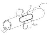
- FIG. 2is a perspective view of the sheet of FIG. 1 formed into a tube, with a medical device cut into it.
- FIG. 3is a top view of the medical device of FIG. 2 .
- FIG. 4is a side view of the medical device of FIG. 2 .
- FIG. 5is a perspective view of the medical device of FIG. 2 .
- a medical deviceis constructed from a composite that includes a high-energy density magnetic material and a biocompatible substance such as a polymer.
- This high-energy density magnetic materialmay be samarium cobalt, neodymium iron boron, aluminum nickel cobalt, or other material. This material initially has a strong and/or uniform magnetic field. Alternately, this material does not have a strong and/or uniform magnetic field, due to a lack of alignment between the individual magnetic domains within the material.
- This high-energy density magnetic materialis then crushed, ground or otherwise processed into a particulate, such as a powder or aggregate.
- the average size of the constituent particles of the particulateis not critical to the invention.
- the particulateis created or sorted such that substantially none of the constituent particles of the particulate are larger than a selected size. However, the particulate may be produced such that the sizes of the individual particles forming the particulate are unconstrained.
- the high-energy density magnetic materialis initially provided in a particulate form, such as a powder or aggregate.
- the high-energy density magnetic material in particulate formis then mixed with a biocompatible material, such as but not limited to a polymer.
- a biocompatible materialsuch as but not limited to a polymer.
- the specific type of biocompatible material usedis not critical to the invention.
- the particulatemay be treated with an agent to reduce surface tension, thereby allowing wetting by the biocompatible material. Such agents are standard.
- the mixing of the magnetic particulate with the biocompatible materialmay be performed when the biocompatible material is in a liquid, partially liquid or colloidal form.
- the magnetic particulateis mixed with the biocompatible material such that the magnetic particulate is substantially uniformly distributed within the biocompatible material.
- the mixtureis then cooled or otherwise treated such that the biocompatible material solidifies by cooling, drying, curing or otherwise transitioning to a solid state.
- the resultis a composite of magnetic particles within a biocompatible material, where the magnetic particles are held within a biocompatible matrix.
- the biocompatible materialis crushed, ground or otherwise formed into a particulate as well, and this particulate is mixed with the magnetic particulate.
- the mixtureis then heated or otherwise treated such that the biocompatible material liquefies, then cooled or otherwise treated such that the biocompatible material solidifies, cures or otherwise transitions to form a composite with magnetic particulate held within a matrix of biocompatible material.
- Other or additional appropriate methods or techniquesmay be used to combine the magnetic particles with the biocompatible material.
- the magnetic particlesmay be coated with gold, gold alloy or other material before they are mixed with the biocompatible material. If coated magnetic particles are present at a surface of the composite material such that the biocompatible material does not cover those particles, the coating of the magnetic material and not the magnetic material itself is exposed to tissue. A standard vapor deposition process may be used to coat the particles with gold or other material.
- the composite materialis formed into a sheet 2 having a thickness 4 .
- the composite materialmay be formed in the configuration of the sheet 2 . Such construction may be advantageous, as the thickness 4 of the sheet 2 may be selected in part to provide for rapid and/or efficient cooling or curing of the composite. Alternately, the composite may be formed in solid bricks, blocks, ingots, or other shapes, after which sheets 2 are individually sliced or cut therefrom, such as by laser cutting.
- the sheet 2can be manipulated, cut, formed, rolled, pressed, stamped, or otherwise acted upon to manufacture at least one component of a medical device.
- the sheet 2can be used as the basis for manufacturing at least one element of a multi-element anastomosis device useful for coronary artery bypass graft (CABG) surgery, carotid artery bypass surgery, or other such surgical procedures.
- CABGcoronary artery bypass graft
- the thickness 4 of the sheet 2is advantageously equal to or less than 0.010 inches.
- the selected size of the largest particle within the particulateis preferably less than the thickness 4 of the sheet 2 . In this way, the particles are sized such that the individual particles do not substantially extend out of any surface of the sheet 2 .
- the sheet 2is rolled into a tube 6 , as shown in FIG. 2 , such that two edges 8 of the sheet 2 substantially abut one another. These edges 8 may be secured together, such as by adhesive, by melting them together, or by other structures, mechanisms and/or methods.
- the tube 6may have a cross section that is substantially circular, substantially elliptical, complex, or shaped differently.
- the tube 6may have a constant diameter along its length, or a variable diameter. Alternately, the edges 8 of the sheet 2 that abut one another in the tube 6 configuration are not secured together.
- the tube 6maintains its tubular shape due to the stiffness of the sheet 2 , by securing the sheet 2 to a mandrel or other fixture, or by other methods, structures and/or mechanisms.
- the sheet 2is rolled into a shape other than a tube 6 such that the edges 8 do not touch.
- Such a shapemay have a semicircular cross-section, or other cross section.
- the tube 6is extruded or otherwise formed from a precursor shape, such as a thicker tube. Other methods may be utilized to form the tube 6 from the composite.
- a laseris then used to cut material from the tube 6 to form a medical device 10 .
- the use of a laser to cut stainless steel tubing into medical devices such as stentsis standard in the art.
- the lasermay be used in a way to cut the medical device 10 from the composite tube 6 .
- a major passage 12is cut within an outer perimeter 14 of the medical device 10 , where the edge of the major passage 12 defines an inner perimeter 20 in the medical device 10 .
- the medical device 10is substantially an annulus bounded by the outer perimeter 14 and the inner perimeter 20 , curved in a manner that corresponds to the curvature of the tube 6 . Due to the curvature of the tube 6 from which it is cut, the annulus is not flat, and thus possesses a compound curvature. Alternately, the medical device 10 is shaped differently.
- a number of minor passages 16are also laser cut through the tube 6 between the outer perimeter 14 and the inner perimeter 20 . These minor passages 16 are advantageously cut through the medical device 10 before the medical device 10 is cut from the tube 6 , to simplify manufacturing. Although the minor passages 16 are shown having substantially triangular shapes, the minor passages 16 may be shaped differently, and may be slots, squares, diamonds, rectangles, polygons, circles, ovals, complex shapes, or any other shape. After the minor passages 16 have been cut, a number of members 18 remain, where the members 18 are defined between adjacent minor passages 16 , between the minor passages 16 and the outer perimeter 14 , and between the minor passages 16 and the inner perimeter 20 .
- the tube 6is then placed in a magnetic field.
- the magnetic fieldis strong enough to cause the individual magnetic domains within the particulate in the composite material to align with one another.
- a magnetic fieldis induced in the tube 6 and the medical device 10 .
- the external magnetic field applied to the tube 6is oriented relative to the tube 6 such that the magnetic polarity of the medical device 10 is in a desired direction.
- the medical device 10is then cut from the tube 6 .
- the medical device 10may then be ready for use, or may then be processed further. Alternately, the medical device 10 is cut from the tube 6 before a magnetic field is induced in it.
- a network of interconnected members 18is formed. That is, as a result of cutting minor passages 16 into the medical device 10 , the medical device 10 is formed from a number of interconnected members 18 .
- the members 18are sized such that they are substantially no larger than 0.010 inches in any dimension. For this reason, the thickness 4 of the sheet 2 is advantageously no larger than 0.010 inches, as described above. It is well established in the literature that members 18 of this size are less thrombogenic in the bloodstream.
- a medical device 10substantially composed of a number of interconnected members 18 each no larger than 0.010 in any dimension can be placed, in whole or in part, in the bloodstream with minimal or no thrombogenic effects, if the material from which the members 18 are constructed is properly chosen.
- stentssuch as those commonly available in the United States and other countries.
- the medical device 10is a piece of a multiple-piece anastomosis device
- the medical device 10may be utilized in accordance with U.S. Pat. No. 6,352,543, which is hereby incorporated by reference in its entirety.
- four medical devices 10 formed by the method described aboveare provided.
- An end of a graft vesselis placed through the major passage 12 of one medical device 10 and everted.
- a second medical device 10is placed against the everted end of the graft vessel, such that magnetic attraction pulls the medical devices 10 together and thereby holds the everted end of the graft vessel securely therebetween.
- a third medical device 10is placed within a target vessel, such that the major passage 12 of the medical device 10 is aligned with an opening in the target vessel.
- a fourth medical device 10is placed against the outside wall of the target vessel, such that magnetic attraction pulls the medical devices 10 together and secures them against the wall of the target vessel. That is, the area of the target vessel in proximity to the opening therein is held between two medical devices 10 . As the end of the graft vessel is moved in proximity to the wall of the target vessel, magnetic attraction causes the medical device 10 placed against the outer wall of the target vessel to contact and hold the medical device 10 placed against the everted end of the graft vessel. The anastomosis is thereby completed.
Landscapes
- Health & Medical Sciences (AREA)
- Life Sciences & Earth Sciences (AREA)
- Surgery (AREA)
- Heart & Thoracic Surgery (AREA)
- Engineering & Computer Science (AREA)
- Biomedical Technology (AREA)
- Nuclear Medicine, Radiotherapy & Molecular Imaging (AREA)
- Medical Informatics (AREA)
- Molecular Biology (AREA)
- Animal Behavior & Ethology (AREA)
- General Health & Medical Sciences (AREA)
- Public Health (AREA)
- Veterinary Medicine (AREA)
- Surgical Instruments (AREA)
- Materials For Medical Uses (AREA)
Abstract
Description
Claims (14)
Priority Applications (1)
| Application Number | Priority Date | Filing Date | Title |
|---|---|---|---|
| US10/235,446US7001402B2 (en) | 2002-09-04 | 2002-09-04 | Medical device having magnetic properties |
Applications Claiming Priority (1)
| Application Number | Priority Date | Filing Date | Title |
|---|---|---|---|
| US10/235,446US7001402B2 (en) | 2002-09-04 | 2002-09-04 | Medical device having magnetic properties |
Publications (2)
| Publication Number | Publication Date |
|---|---|
| US20040087983A1 US20040087983A1 (en) | 2004-05-06 |
| US7001402B2true US7001402B2 (en) | 2006-02-21 |
Family
ID=32174472
Family Applications (1)
| Application Number | Title | Priority Date | Filing Date |
|---|---|---|---|
| US10/235,446Expired - Fee RelatedUS7001402B2 (en) | 2002-09-04 | 2002-09-04 | Medical device having magnetic properties |
Country Status (1)
| Country | Link |
|---|---|
| US (1) | US7001402B2 (en) |
Cited By (8)
| Publication number | Priority date | Publication date | Assignee | Title |
|---|---|---|---|---|
| US20060074448A1 (en)* | 2004-09-29 | 2006-04-06 | The Regents Of The University Of California | Apparatus and methods for magnetic alteration of deformities |
| US20060079897A1 (en)* | 2004-09-29 | 2006-04-13 | Harrison Michael R | Apparatus and methods for magnetic alteration of anatomical features |
| US20060271107A1 (en)* | 2004-09-29 | 2006-11-30 | Harrison Michael R | Apparatus and methods for magnetic alteration of anatomical features |
| US20070270629A1 (en)* | 2006-05-19 | 2007-11-22 | Charles Filipi J | System and techniques for magnetic manipulation of internal organs during minimally invasive surgery |
| US20070276378A1 (en)* | 2004-09-29 | 2007-11-29 | The Regents Of The University Of California | Apparatus and methods for magnetic alteration of anatomical features |
| US20090048618A1 (en)* | 2004-09-29 | 2009-02-19 | The Regents Of The University Of California | Apparatus and method for magnetic alteration of anatomical features |
| US20100114103A1 (en)* | 2008-11-06 | 2010-05-06 | The Regents Of The University Of California | Apparatus and methods for alteration of anatomical features |
| US11607223B2 (en) | 2017-06-30 | 2023-03-21 | The Regents Of The University Of California | Magnetic devices, systems, and methods |
Citations (10)
| Publication number | Priority date | Publication date | Assignee | Title |
|---|---|---|---|---|
| US2999275A (en)* | 1958-07-15 | 1961-09-12 | Leyman Corp | Mechanical orientation of magnetically anisotropic particles |
| US4028255A (en)* | 1973-01-31 | 1977-06-07 | Ici Australia Limited | Preparation of polymer composites |
| US4873504A (en)* | 1987-02-25 | 1989-10-10 | The Electrodyne Company, Inc. | Bonded high energy rare earth permanent magnets |
| WO2001017440A1 (en) | 1999-09-10 | 2001-03-15 | Ventrica, Inc. | Anastomotic device and methods for placement |
| WO2001082803A1 (en) | 2000-04-29 | 2001-11-08 | Ventrica, Inc. | Methods and devices using magnetic force to form an anastomosis between hollow bodies |
| WO2002013698A1 (en) | 2000-08-12 | 2002-02-21 | Ventrica, Inc. | Processes for producing anastomotic components having magnetic properties |
| US6491842B1 (en)* | 1998-02-14 | 2002-12-10 | Studiengesellschaft Kohle Mbh | Anticorrosive magnetic nanocolloids protected by precious metals |
| US6555018B2 (en)* | 2001-02-28 | 2003-04-29 | Magnequench, Inc. | Bonded magnets made with atomized permanent magnetic powders |
| US6641919B1 (en)* | 1998-12-07 | 2003-11-04 | Sumitomo Metal Mining Co., Ltd. | Resin-bonded magnet |
| US6673104B2 (en)* | 2001-03-15 | 2004-01-06 | Scimed Life Systems, Inc. | Magnetic stent |
- 2002
- 2002-09-04USUS10/235,446patent/US7001402B2/ennot_activeExpired - Fee Related
Patent Citations (14)
| Publication number | Priority date | Publication date | Assignee | Title |
|---|---|---|---|---|
| US2999275A (en)* | 1958-07-15 | 1961-09-12 | Leyman Corp | Mechanical orientation of magnetically anisotropic particles |
| US4028255A (en)* | 1973-01-31 | 1977-06-07 | Ici Australia Limited | Preparation of polymer composites |
| US4873504A (en)* | 1987-02-25 | 1989-10-10 | The Electrodyne Company, Inc. | Bonded high energy rare earth permanent magnets |
| US6491842B1 (en)* | 1998-02-14 | 2002-12-10 | Studiengesellschaft Kohle Mbh | Anticorrosive magnetic nanocolloids protected by precious metals |
| US6641919B1 (en)* | 1998-12-07 | 2003-11-04 | Sumitomo Metal Mining Co., Ltd. | Resin-bonded magnet |
| WO2001017440A1 (en) | 1999-09-10 | 2001-03-15 | Ventrica, Inc. | Anastomotic device and methods for placement |
| US6352543B1 (en) | 2000-04-29 | 2002-03-05 | Ventrica, Inc. | Methods for forming anastomoses using magnetic force |
| WO2001082803A1 (en) | 2000-04-29 | 2001-11-08 | Ventrica, Inc. | Methods and devices using magnetic force to form an anastomosis between hollow bodies |
| WO2002013704A1 (en) | 2000-08-12 | 2002-02-21 | Ventrica, Inc. | Devices and methods for forming magnetic anastomoses and ports in vessels |
| WO2002013699A1 (en) | 2000-08-12 | 2002-02-21 | Ventrica, Inc. | Extravascular anastomotic components and methods for forming magnetic anastomoses |
| WO2002013703A1 (en) | 2000-08-12 | 2002-02-21 | Ventrica, Inc. | Magnetic components for forming anastomoses and creating ports in vessels |
| WO2002013698A1 (en) | 2000-08-12 | 2002-02-21 | Ventrica, Inc. | Processes for producing anastomotic components having magnetic properties |
| US6555018B2 (en)* | 2001-02-28 | 2003-04-29 | Magnequench, Inc. | Bonded magnets made with atomized permanent magnetic powders |
| US6673104B2 (en)* | 2001-03-15 | 2004-01-06 | Scimed Life Systems, Inc. | Magnetic stent |
Cited By (11)
| Publication number | Priority date | Publication date | Assignee | Title |
|---|---|---|---|---|
| US20060074448A1 (en)* | 2004-09-29 | 2006-04-06 | The Regents Of The University Of California | Apparatus and methods for magnetic alteration of deformities |
| US20060079897A1 (en)* | 2004-09-29 | 2006-04-13 | Harrison Michael R | Apparatus and methods for magnetic alteration of anatomical features |
| US20060271107A1 (en)* | 2004-09-29 | 2006-11-30 | Harrison Michael R | Apparatus and methods for magnetic alteration of anatomical features |
| US20070276378A1 (en)* | 2004-09-29 | 2007-11-29 | The Regents Of The University Of California | Apparatus and methods for magnetic alteration of anatomical features |
| US20090048618A1 (en)* | 2004-09-29 | 2009-02-19 | The Regents Of The University Of California | Apparatus and method for magnetic alteration of anatomical features |
| US8043290B2 (en) | 2004-09-29 | 2011-10-25 | The Regents Of The University Of California, San Francisco | Apparatus and methods for magnetic alteration of deformities |
| US8142454B2 (en) | 2004-09-29 | 2012-03-27 | The Regents Of The University Of California, San Francisco | Apparatus and method for magnetic alteration of anatomical features |
| US8439915B2 (en) | 2004-09-29 | 2013-05-14 | The Regents Of The University Of California | Apparatus and methods for magnetic alteration of anatomical features |
| US20070270629A1 (en)* | 2006-05-19 | 2007-11-22 | Charles Filipi J | System and techniques for magnetic manipulation of internal organs during minimally invasive surgery |
| US20100114103A1 (en)* | 2008-11-06 | 2010-05-06 | The Regents Of The University Of California | Apparatus and methods for alteration of anatomical features |
| US11607223B2 (en) | 2017-06-30 | 2023-03-21 | The Regents Of The University Of California | Magnetic devices, systems, and methods |
Also Published As
| Publication number | Publication date |
|---|---|
| US20040087983A1 (en) | 2004-05-06 |
Similar Documents
| Publication | Publication Date | Title |
|---|---|---|
| US6932827B2 (en) | Methods and devices using magnetic force to form an anastomosis between hollow bodies | |
| JP4934269B2 (en) | Medical graft with multiple micropores | |
| US20020072758A1 (en) | Processes for producing anastomotic components having magnetic properties | |
| CA2657682C (en) | Stent | |
| US11766506B2 (en) | Stent device for spinal fusion | |
| US10711334B2 (en) | Metal alloy for medical devices | |
| JP3544550B2 (en) | Artificial prosthesis member and method of manufacturing the same | |
| JP4799412B2 (en) | Implantable metal graft and method for producing the same | |
| US7001402B2 (en) | Medical device having magnetic properties | |
| US20100042206A1 (en) | Bioabsorbable coatings for medical devices | |
| US7490396B2 (en) | Method of making metal wire with filaments for biomedical applications | |
| US20060264914A1 (en) | Metal alloys for medical devices | |
| US20190008995A1 (en) | Molybdenum Alloys for Medical Devices | |
| JP2003522002A (en) | Non-thrombotic implantable device | |
| BRPI0807039A2 (en) | PORTABLE, DEGRADABLE IMPLANT MADE BY POWDER MOLDING. | |
| KR20120123331A (en) | Endoprosthesis containing multi-phase ferrous steel | |
| CA2583252A1 (en) | Medical devices and methods of making the same | |
| JP2008541853A (en) | Medical device | |
| US20200254140A1 (en) | Alloy For Medical Device | |
| WO2012122567A2 (en) | Anti-thrombogenic heart valve and medical implements | |
| CA2387282A1 (en) | Processes for producing anastomotic components having magnetic properties | |
| CN112584876A (en) | Iron-based biodegradable metals for implantable medical devices | |
| CA2680229A1 (en) | Bioabsorbable coatings for medical devices | |
| DE10113659A1 (en) | Stent for treating arteriosclerosis is made of magnetic alloy with specified permeability and Curie temperature, for self-controlled, limited induction heating to prevent re-stenosis | |
| EP2170423A2 (en) | Implant, and method for the production thereof |
Legal Events
| Date | Code | Title | Description |
|---|---|---|---|
| AS | Assignment | Owner name:CARDICA, INC., CALIFORNIA Free format text:ASSIGNMENT OF ASSIGNORS INTEREST;ASSIGNOR:YENCHO, STEPHEN A.;REEL/FRAME:013275/0674 Effective date:20020830 | |
| AS | Assignment | Owner name:CEMTURY MEDICAL, JAPAN Free format text:SECURITY AGREEMENT;ASSIGNOR:CARDICA, INC.;REEL/FRAME:014154/0925 Effective date:20030619 Owner name:DALE ARAKI, ESQ., CALIFORNIA Free format text:SECURITY AGREEMENT;ASSIGNOR:CARDICA, INC.;REEL/FRAME:014154/0925 Effective date:20030619 | |
| AS | Assignment | Owner name:GUIDANT INVESTMENT CORPORATION, CALIFORNIA Free format text:SECURITY AGREEMENT;ASSIGNOR:CARDICA, INC.;REEL/FRAME:013900/0414 Effective date:20030819 | |
| AS | Assignment | Owner name:CARDICA, INC., CALIFORNIA Free format text:RELEASE BY SECURED PARTY;ASSIGNOR:VENTURE LENDING AND LEASING III, INC.;REEL/FRAME:016967/0291 Effective date:20051228 | |
| AS | Assignment | Owner name:CARDICA, INC., CALIFORNIA Free format text:RELEASE BY SECURED PARTY;ASSIGNOR:GUIDANT INVESTMENT CORPORATION;REEL/FRAME:021912/0073 Effective date:20081023 | |
| REMI | Maintenance fee reminder mailed | ||
| LAPS | Lapse for failure to pay maintenance fees | ||
| STCH | Information on status: patent discontinuation | Free format text:PATENT EXPIRED DUE TO NONPAYMENT OF MAINTENANCE FEES UNDER 37 CFR 1.362 | |
| FP | Lapsed due to failure to pay maintenance fee | Effective date:20100221 | |
| AS | Assignment | Owner name:CARDICA, INC., CALIFORNIA Free format text:RELEASE BY SECURED PARTY;ASSIGNOR:CENTURY MEDICAL, INC.;REEL/FRAME:025311/0890 Effective date:20100928 | |
| AS | Assignment | Owner name:AESCULAP AG, GERMANY Free format text:ASSET PURCHASE AGREEMENT;ASSIGNOR:AESDEX, LLC;REEL/FRAME:045870/0567 Effective date:20180220 Owner name:AESDEX, LLC, PENNSYLVANIA Free format text:ASSIGNMENT OF ASSIGNORS INTEREST;ASSIGNOR:DEXTERA SURGICAL INC.;REEL/FRAME:045870/0478 Effective date:20180214 |