US7001390B2 - Anchoring element for anchoring a ligament transplant - Google Patents
Anchoring element for anchoring a ligament transplantDownload PDFInfo
- Publication number
- US7001390B2 US7001390B2US10/361,741US36174103AUS7001390B2US 7001390 B2US7001390 B2US 7001390B2US 36174103 AUS36174103 AUS 36174103AUS 7001390 B2US7001390 B2US 7001390B2
- Authority
- US
- United States
- Prior art keywords
- channel
- anchoring element
- ligament
- bone
- transplant
- Prior art date
- Legal status (The legal status is an assumption and is not a legal conclusion. Google has not performed a legal analysis and makes no representation as to the accuracy of the status listed.)
- Expired - Fee Related, expires
Links
- 238000004873anchoringMethods0.000titleclaimsabstractdescription63
- 210000003041ligamentAnatomy0.000titleclaimsabstractdescription57
- 210000000988bone and boneAnatomy0.000claimsabstractdescription36
- 239000002245particleSubstances0.000claimsabstractdescription16
- 239000000463materialSubstances0.000claimsdescription37
- 238000000034methodMethods0.000claimsdescription13
- 238000005553drillingMethods0.000claimsdescription2
- 238000004519manufacturing processMethods0.000claimsdescription2
- 210000002435tendonAnatomy0.000description21
- 238000013461designMethods0.000description8
- 238000001356surgical procedureMethods0.000description7
- 210000000689upper legAnatomy0.000description7
- 210000000629knee jointAnatomy0.000description5
- 230000000694effectsEffects0.000description4
- 210000001503jointAnatomy0.000description3
- 230000033001locomotionEffects0.000description3
- 210000000426patellar ligamentAnatomy0.000description3
- 210000002303tibiaAnatomy0.000description3
- 230000002349favourable effectEffects0.000description2
- 239000012530fluidSubstances0.000description2
- 239000007943implantSubstances0.000description2
- 230000010354integrationEffects0.000description2
- 210000000323shoulder jointAnatomy0.000description2
- 239000007787solidSubstances0.000description2
- LCSKNASZPVZHEG-UHFFFAOYSA-N3,6-dimethyl-1,4-dioxane-2,5-dione;1,4-dioxane-2,5-dioneChemical compoundO=C1COC(=O)CO1.CC1OC(=O)C(C)OC1=OLCSKNASZPVZHEG-UHFFFAOYSA-N0.000description1
- 230000006978adaptationEffects0.000description1
- 238000013459approachMethods0.000description1
- 210000000544articulatio talocruralisAnatomy0.000description1
- 230000015572biosynthetic processEffects0.000description1
- 210000002805bone matrixAnatomy0.000description1
- 210000000845cartilageAnatomy0.000description1
- 238000006243chemical reactionMethods0.000description1
- 239000002131composite materialSubstances0.000description1
- 230000006735deficitEffects0.000description1
- 230000001419dependent effectEffects0.000description1
- 230000001771impaired effectEffects0.000description1
- 210000003127kneeAnatomy0.000description1
- 230000007774longtermEffects0.000description1
- 239000007769metal materialSubstances0.000description1
- 239000000203mixtureSubstances0.000description1
- 238000012986modificationMethods0.000description1
- 230000004048modificationEffects0.000description1
- 238000012544monitoring processMethods0.000description1
- 210000000056organAnatomy0.000description1
- 210000000963osteoblastAnatomy0.000description1
- 239000011236particulate materialSubstances0.000description1
- 230000002093peripheral effectEffects0.000description1
- 238000003825pressingMethods0.000description1
- 239000004576sandSubstances0.000description1
- 231100000241scarToxicity0.000description1
- 238000009958sewingMethods0.000description1
- 239000000126substanceSubstances0.000description1
- 239000000725suspensionSubstances0.000description1
- 210000001179synovial fluidAnatomy0.000description1
- 210000001519tissueAnatomy0.000description1
- 238000012546transferMethods0.000description1
Images


Classifications
- A—HUMAN NECESSITIES
- A61—MEDICAL OR VETERINARY SCIENCE; HYGIENE
- A61F—FILTERS IMPLANTABLE INTO BLOOD VESSELS; PROSTHESES; DEVICES PROVIDING PATENCY TO, OR PREVENTING COLLAPSING OF, TUBULAR STRUCTURES OF THE BODY, e.g. STENTS; ORTHOPAEDIC, NURSING OR CONTRACEPTIVE DEVICES; FOMENTATION; TREATMENT OR PROTECTION OF EYES OR EARS; BANDAGES, DRESSINGS OR ABSORBENT PADS; FIRST-AID KITS
- A61F2/00—Filters implantable into blood vessels; Prostheses, i.e. artificial substitutes or replacements for parts of the body; Appliances for connecting them with the body; Devices providing patency to, or preventing collapsing of, tubular structures of the body, e.g. stents
- A61F2/02—Prostheses implantable into the body
- A61F2/08—Muscles; Tendons; Ligaments
- A61F2/0811—Fixation devices for tendons or ligaments
- A—HUMAN NECESSITIES
- A61—MEDICAL OR VETERINARY SCIENCE; HYGIENE
- A61B—DIAGNOSIS; SURGERY; IDENTIFICATION
- A61B17/00—Surgical instruments, devices or methods
- A61B17/04—Surgical instruments, devices or methods for suturing wounds; Holders or packages for needles or suture materials
- A61B17/06—Needles ; Sutures; Needle-suture combinations; Holders or packages for needles or suture materials
- A61B17/06166—Sutures
- A—HUMAN NECESSITIES
- A61—MEDICAL OR VETERINARY SCIENCE; HYGIENE
- A61F—FILTERS IMPLANTABLE INTO BLOOD VESSELS; PROSTHESES; DEVICES PROVIDING PATENCY TO, OR PREVENTING COLLAPSING OF, TUBULAR STRUCTURES OF THE BODY, e.g. STENTS; ORTHOPAEDIC, NURSING OR CONTRACEPTIVE DEVICES; FOMENTATION; TREATMENT OR PROTECTION OF EYES OR EARS; BANDAGES, DRESSINGS OR ABSORBENT PADS; FIRST-AID KITS
- A61F2/00—Filters implantable into blood vessels; Prostheses, i.e. artificial substitutes or replacements for parts of the body; Appliances for connecting them with the body; Devices providing patency to, or preventing collapsing of, tubular structures of the body, e.g. stents
- A61F2/02—Prostheses implantable into the body
- A61F2/08—Muscles; Tendons; Ligaments
- A61F2/0811—Fixation devices for tendons or ligaments
- A61F2002/0817—Structure of the anchor
- A61F2002/0823—Modular anchors comprising a plurality of separate parts
- A61F2002/0829—Modular anchors comprising a plurality of separate parts without deformation of anchor parts, e.g. fixation screws on bone surface, extending barbs, cams, butterflies, spring-loaded pins
- A—HUMAN NECESSITIES
- A61—MEDICAL OR VETERINARY SCIENCE; HYGIENE
- A61F—FILTERS IMPLANTABLE INTO BLOOD VESSELS; PROSTHESES; DEVICES PROVIDING PATENCY TO, OR PREVENTING COLLAPSING OF, TUBULAR STRUCTURES OF THE BODY, e.g. STENTS; ORTHOPAEDIC, NURSING OR CONTRACEPTIVE DEVICES; FOMENTATION; TREATMENT OR PROTECTION OF EYES OR EARS; BANDAGES, DRESSINGS OR ABSORBENT PADS; FIRST-AID KITS
- A61F2/00—Filters implantable into blood vessels; Prostheses, i.e. artificial substitutes or replacements for parts of the body; Appliances for connecting them with the body; Devices providing patency to, or preventing collapsing of, tubular structures of the body, e.g. stents
- A61F2/02—Prostheses implantable into the body
- A61F2/08—Muscles; Tendons; Ligaments
- A61F2/0811—Fixation devices for tendons or ligaments
- A61F2002/0847—Mode of fixation of anchor to tendon or ligament
- A61F2002/0852—Fixation of a loop or U-turn, e.g. eyelets, anchor having multiple holes
- A—HUMAN NECESSITIES
- A61—MEDICAL OR VETERINARY SCIENCE; HYGIENE
- A61F—FILTERS IMPLANTABLE INTO BLOOD VESSELS; PROSTHESES; DEVICES PROVIDING PATENCY TO, OR PREVENTING COLLAPSING OF, TUBULAR STRUCTURES OF THE BODY, e.g. STENTS; ORTHOPAEDIC, NURSING OR CONTRACEPTIVE DEVICES; FOMENTATION; TREATMENT OR PROTECTION OF EYES OR EARS; BANDAGES, DRESSINGS OR ABSORBENT PADS; FIRST-AID KITS
- A61F2/00—Filters implantable into blood vessels; Prostheses, i.e. artificial substitutes or replacements for parts of the body; Appliances for connecting them with the body; Devices providing patency to, or preventing collapsing of, tubular structures of the body, e.g. stents
- A61F2/02—Prostheses implantable into the body
- A61F2/08—Muscles; Tendons; Ligaments
- A61F2/0811—Fixation devices for tendons or ligaments
- A61F2002/0847—Mode of fixation of anchor to tendon or ligament
- A61F2002/0858—Fixation of tendon or ligament between anchor and bone, e.g. interference screws, wedges
- A—HUMAN NECESSITIES
- A61—MEDICAL OR VETERINARY SCIENCE; HYGIENE
- A61F—FILTERS IMPLANTABLE INTO BLOOD VESSELS; PROSTHESES; DEVICES PROVIDING PATENCY TO, OR PREVENTING COLLAPSING OF, TUBULAR STRUCTURES OF THE BODY, e.g. STENTS; ORTHOPAEDIC, NURSING OR CONTRACEPTIVE DEVICES; FOMENTATION; TREATMENT OR PROTECTION OF EYES OR EARS; BANDAGES, DRESSINGS OR ABSORBENT PADS; FIRST-AID KITS
- A61F2/00—Filters implantable into blood vessels; Prostheses, i.e. artificial substitutes or replacements for parts of the body; Appliances for connecting them with the body; Devices providing patency to, or preventing collapsing of, tubular structures of the body, e.g. stents
- A61F2/02—Prostheses implantable into the body
- A61F2/08—Muscles; Tendons; Ligaments
- A61F2/0811—Fixation devices for tendons or ligaments
- A61F2002/0847—Mode of fixation of anchor to tendon or ligament
- A61F2002/0864—Fixation of tendon or ligament between anchor elements, e.g. by additional screws in the anchor, anchor crimped around tendon
- A—HUMAN NECESSITIES
- A61—MEDICAL OR VETERINARY SCIENCE; HYGIENE
- A61F—FILTERS IMPLANTABLE INTO BLOOD VESSELS; PROSTHESES; DEVICES PROVIDING PATENCY TO, OR PREVENTING COLLAPSING OF, TUBULAR STRUCTURES OF THE BODY, e.g. STENTS; ORTHOPAEDIC, NURSING OR CONTRACEPTIVE DEVICES; FOMENTATION; TREATMENT OR PROTECTION OF EYES OR EARS; BANDAGES, DRESSINGS OR ABSORBENT PADS; FIRST-AID KITS
- A61F2/00—Filters implantable into blood vessels; Prostheses, i.e. artificial substitutes or replacements for parts of the body; Appliances for connecting them with the body; Devices providing patency to, or preventing collapsing of, tubular structures of the body, e.g. stents
- A61F2/02—Prostheses implantable into the body
- A61F2/08—Muscles; Tendons; Ligaments
- A61F2/0811—Fixation devices for tendons or ligaments
- A61F2002/0876—Position of anchor in respect to the bone
- A61F2002/0882—Anchor in or on top of a bone tunnel, i.e. a hole running through the entire bone
- A—HUMAN NECESSITIES
- A61—MEDICAL OR VETERINARY SCIENCE; HYGIENE
- A61F—FILTERS IMPLANTABLE INTO BLOOD VESSELS; PROSTHESES; DEVICES PROVIDING PATENCY TO, OR PREVENTING COLLAPSING OF, TUBULAR STRUCTURES OF THE BODY, e.g. STENTS; ORTHOPAEDIC, NURSING OR CONTRACEPTIVE DEVICES; FOMENTATION; TREATMENT OR PROTECTION OF EYES OR EARS; BANDAGES, DRESSINGS OR ABSORBENT PADS; FIRST-AID KITS
- A61F2/00—Filters implantable into blood vessels; Prostheses, i.e. artificial substitutes or replacements for parts of the body; Appliances for connecting them with the body; Devices providing patency to, or preventing collapsing of, tubular structures of the body, e.g. stents
- A61F2/02—Prostheses implantable into the body
- A61F2/28—Bones
- A61F2002/2835—Bone graft implants for filling a bony defect or an endoprosthesis cavity, e.g. by synthetic material or biological material
- A—HUMAN NECESSITIES
- A61—MEDICAL OR VETERINARY SCIENCE; HYGIENE
- A61F—FILTERS IMPLANTABLE INTO BLOOD VESSELS; PROSTHESES; DEVICES PROVIDING PATENCY TO, OR PREVENTING COLLAPSING OF, TUBULAR STRUCTURES OF THE BODY, e.g. STENTS; ORTHOPAEDIC, NURSING OR CONTRACEPTIVE DEVICES; FOMENTATION; TREATMENT OR PROTECTION OF EYES OR EARS; BANDAGES, DRESSINGS OR ABSORBENT PADS; FIRST-AID KITS
- A61F2/00—Filters implantable into blood vessels; Prostheses, i.e. artificial substitutes or replacements for parts of the body; Appliances for connecting them with the body; Devices providing patency to, or preventing collapsing of, tubular structures of the body, e.g. stents
- A61F2/02—Prostheses implantable into the body
- A61F2/30—Joints
- A61F2002/30001—Additional features of subject-matter classified in A61F2/28, A61F2/30 and subgroups thereof
- A61F2002/30003—Material related properties of the prosthesis or of a coating on the prosthesis
- A61F2002/3006—Properties of materials and coating materials
- A61F2002/30062—(bio)absorbable, biodegradable, bioerodable, (bio)resorbable, resorptive
- A—HUMAN NECESSITIES
- A61—MEDICAL OR VETERINARY SCIENCE; HYGIENE
- A61F—FILTERS IMPLANTABLE INTO BLOOD VESSELS; PROSTHESES; DEVICES PROVIDING PATENCY TO, OR PREVENTING COLLAPSING OF, TUBULAR STRUCTURES OF THE BODY, e.g. STENTS; ORTHOPAEDIC, NURSING OR CONTRACEPTIVE DEVICES; FOMENTATION; TREATMENT OR PROTECTION OF EYES OR EARS; BANDAGES, DRESSINGS OR ABSORBENT PADS; FIRST-AID KITS
- A61F2/00—Filters implantable into blood vessels; Prostheses, i.e. artificial substitutes or replacements for parts of the body; Appliances for connecting them with the body; Devices providing patency to, or preventing collapsing of, tubular structures of the body, e.g. stents
- A61F2/02—Prostheses implantable into the body
- A61F2/30—Joints
- A61F2002/30001—Additional features of subject-matter classified in A61F2/28, A61F2/30 and subgroups thereof
- A61F2002/30108—Shapes
- A61F2002/3011—Cross-sections or two-dimensional shapes
- A61F2002/30112—Rounded shapes, e.g. with rounded corners
- A61F2002/30113—Rounded shapes, e.g. with rounded corners circular
- A—HUMAN NECESSITIES
- A61—MEDICAL OR VETERINARY SCIENCE; HYGIENE
- A61F—FILTERS IMPLANTABLE INTO BLOOD VESSELS; PROSTHESES; DEVICES PROVIDING PATENCY TO, OR PREVENTING COLLAPSING OF, TUBULAR STRUCTURES OF THE BODY, e.g. STENTS; ORTHOPAEDIC, NURSING OR CONTRACEPTIVE DEVICES; FOMENTATION; TREATMENT OR PROTECTION OF EYES OR EARS; BANDAGES, DRESSINGS OR ABSORBENT PADS; FIRST-AID KITS
- A61F2/00—Filters implantable into blood vessels; Prostheses, i.e. artificial substitutes or replacements for parts of the body; Appliances for connecting them with the body; Devices providing patency to, or preventing collapsing of, tubular structures of the body, e.g. stents
- A61F2/02—Prostheses implantable into the body
- A61F2/30—Joints
- A61F2002/30001—Additional features of subject-matter classified in A61F2/28, A61F2/30 and subgroups thereof
- A61F2002/30108—Shapes
- A61F2002/3011—Cross-sections or two-dimensional shapes
- A61F2002/30112—Rounded shapes, e.g. with rounded corners
- A61F2002/30131—Rounded shapes, e.g. with rounded corners horseshoe- or crescent- or C-shaped or U-shaped
- A—HUMAN NECESSITIES
- A61—MEDICAL OR VETERINARY SCIENCE; HYGIENE
- A61F—FILTERS IMPLANTABLE INTO BLOOD VESSELS; PROSTHESES; DEVICES PROVIDING PATENCY TO, OR PREVENTING COLLAPSING OF, TUBULAR STRUCTURES OF THE BODY, e.g. STENTS; ORTHOPAEDIC, NURSING OR CONTRACEPTIVE DEVICES; FOMENTATION; TREATMENT OR PROTECTION OF EYES OR EARS; BANDAGES, DRESSINGS OR ABSORBENT PADS; FIRST-AID KITS
- A61F2/00—Filters implantable into blood vessels; Prostheses, i.e. artificial substitutes or replacements for parts of the body; Appliances for connecting them with the body; Devices providing patency to, or preventing collapsing of, tubular structures of the body, e.g. stents
- A61F2/02—Prostheses implantable into the body
- A61F2/30—Joints
- A61F2002/30001—Additional features of subject-matter classified in A61F2/28, A61F2/30 and subgroups thereof
- A61F2002/30108—Shapes
- A61F2002/30199—Three-dimensional shapes
- A61F2002/30205—Three-dimensional shapes conical
- A61F2002/3021—Three-dimensional shapes conical frustoconical
- A—HUMAN NECESSITIES
- A61—MEDICAL OR VETERINARY SCIENCE; HYGIENE
- A61F—FILTERS IMPLANTABLE INTO BLOOD VESSELS; PROSTHESES; DEVICES PROVIDING PATENCY TO, OR PREVENTING COLLAPSING OF, TUBULAR STRUCTURES OF THE BODY, e.g. STENTS; ORTHOPAEDIC, NURSING OR CONTRACEPTIVE DEVICES; FOMENTATION; TREATMENT OR PROTECTION OF EYES OR EARS; BANDAGES, DRESSINGS OR ABSORBENT PADS; FIRST-AID KITS
- A61F2/00—Filters implantable into blood vessels; Prostheses, i.e. artificial substitutes or replacements for parts of the body; Appliances for connecting them with the body; Devices providing patency to, or preventing collapsing of, tubular structures of the body, e.g. stents
- A61F2/02—Prostheses implantable into the body
- A61F2/30—Joints
- A61F2002/30001—Additional features of subject-matter classified in A61F2/28, A61F2/30 and subgroups thereof
- A61F2002/30108—Shapes
- A61F2002/30199—Three-dimensional shapes
- A61F2002/30224—Three-dimensional shapes cylindrical
- A—HUMAN NECESSITIES
- A61—MEDICAL OR VETERINARY SCIENCE; HYGIENE
- A61F—FILTERS IMPLANTABLE INTO BLOOD VESSELS; PROSTHESES; DEVICES PROVIDING PATENCY TO, OR PREVENTING COLLAPSING OF, TUBULAR STRUCTURES OF THE BODY, e.g. STENTS; ORTHOPAEDIC, NURSING OR CONTRACEPTIVE DEVICES; FOMENTATION; TREATMENT OR PROTECTION OF EYES OR EARS; BANDAGES, DRESSINGS OR ABSORBENT PADS; FIRST-AID KITS
- A61F2/00—Filters implantable into blood vessels; Prostheses, i.e. artificial substitutes or replacements for parts of the body; Appliances for connecting them with the body; Devices providing patency to, or preventing collapsing of, tubular structures of the body, e.g. stents
- A61F2/02—Prostheses implantable into the body
- A61F2/30—Joints
- A61F2002/30001—Additional features of subject-matter classified in A61F2/28, A61F2/30 and subgroups thereof
- A61F2002/30316—The prosthesis having different structural features at different locations within the same prosthesis; Connections between prosthetic parts; Special structural features of bone or joint prostheses not otherwise provided for
- A61F2002/30329—Connections or couplings between prosthetic parts, e.g. between modular parts; Connecting elements
- A61F2002/30461—Connections or couplings between prosthetic parts, e.g. between modular parts; Connecting elements sutured, ligatured or stitched
- A—HUMAN NECESSITIES
- A61—MEDICAL OR VETERINARY SCIENCE; HYGIENE
- A61F—FILTERS IMPLANTABLE INTO BLOOD VESSELS; PROSTHESES; DEVICES PROVIDING PATENCY TO, OR PREVENTING COLLAPSING OF, TUBULAR STRUCTURES OF THE BODY, e.g. STENTS; ORTHOPAEDIC, NURSING OR CONTRACEPTIVE DEVICES; FOMENTATION; TREATMENT OR PROTECTION OF EYES OR EARS; BANDAGES, DRESSINGS OR ABSORBENT PADS; FIRST-AID KITS
- A61F2/00—Filters implantable into blood vessels; Prostheses, i.e. artificial substitutes or replacements for parts of the body; Appliances for connecting them with the body; Devices providing patency to, or preventing collapsing of, tubular structures of the body, e.g. stents
- A61F2/02—Prostheses implantable into the body
- A61F2/30—Joints
- A61F2002/30001—Additional features of subject-matter classified in A61F2/28, A61F2/30 and subgroups thereof
- A61F2002/30316—The prosthesis having different structural features at different locations within the same prosthesis; Connections between prosthetic parts; Special structural features of bone or joint prostheses not otherwise provided for
- A61F2002/30535—Special structural features of bone or joint prostheses not otherwise provided for
- A61F2002/30581—Special structural features of bone or joint prostheses not otherwise provided for having a pocket filled with fluid, e.g. liquid
- A61F2002/30588—Special structural features of bone or joint prostheses not otherwise provided for having a pocket filled with fluid, e.g. liquid filled with solid particles
- A—HUMAN NECESSITIES
- A61—MEDICAL OR VETERINARY SCIENCE; HYGIENE
- A61F—FILTERS IMPLANTABLE INTO BLOOD VESSELS; PROSTHESES; DEVICES PROVIDING PATENCY TO, OR PREVENTING COLLAPSING OF, TUBULAR STRUCTURES OF THE BODY, e.g. STENTS; ORTHOPAEDIC, NURSING OR CONTRACEPTIVE DEVICES; FOMENTATION; TREATMENT OR PROTECTION OF EYES OR EARS; BANDAGES, DRESSINGS OR ABSORBENT PADS; FIRST-AID KITS
- A61F2210/00—Particular material properties of prostheses classified in groups A61F2/00 - A61F2/26 or A61F2/82 or A61F9/00 or A61F11/00 or subgroups thereof
- A61F2210/0004—Particular material properties of prostheses classified in groups A61F2/00 - A61F2/26 or A61F2/82 or A61F9/00 or A61F11/00 or subgroups thereof bioabsorbable
- A—HUMAN NECESSITIES
- A61—MEDICAL OR VETERINARY SCIENCE; HYGIENE
- A61F—FILTERS IMPLANTABLE INTO BLOOD VESSELS; PROSTHESES; DEVICES PROVIDING PATENCY TO, OR PREVENTING COLLAPSING OF, TUBULAR STRUCTURES OF THE BODY, e.g. STENTS; ORTHOPAEDIC, NURSING OR CONTRACEPTIVE DEVICES; FOMENTATION; TREATMENT OR PROTECTION OF EYES OR EARS; BANDAGES, DRESSINGS OR ABSORBENT PADS; FIRST-AID KITS
- A61F2220/00—Fixations or connections for prostheses classified in groups A61F2/00 - A61F2/26 or A61F2/82 or A61F9/00 or A61F11/00 or subgroups thereof
- A61F2220/0025—Connections or couplings between prosthetic parts, e.g. between modular parts; Connecting elements
- A61F2220/0075—Connections or couplings between prosthetic parts, e.g. between modular parts; Connecting elements sutured, ligatured or stitched, retained or tied with a rope, string, thread, wire or cable
- A—HUMAN NECESSITIES
- A61—MEDICAL OR VETERINARY SCIENCE; HYGIENE
- A61F—FILTERS IMPLANTABLE INTO BLOOD VESSELS; PROSTHESES; DEVICES PROVIDING PATENCY TO, OR PREVENTING COLLAPSING OF, TUBULAR STRUCTURES OF THE BODY, e.g. STENTS; ORTHOPAEDIC, NURSING OR CONTRACEPTIVE DEVICES; FOMENTATION; TREATMENT OR PROTECTION OF EYES OR EARS; BANDAGES, DRESSINGS OR ABSORBENT PADS; FIRST-AID KITS
- A61F2230/00—Geometry of prostheses classified in groups A61F2/00 - A61F2/26 or A61F2/82 or A61F9/00 or A61F11/00 or subgroups thereof
- A61F2230/0002—Two-dimensional shapes, e.g. cross-sections
- A61F2230/0004—Rounded shapes, e.g. with rounded corners
- A61F2230/0006—Rounded shapes, e.g. with rounded corners circular
- A—HUMAN NECESSITIES
- A61—MEDICAL OR VETERINARY SCIENCE; HYGIENE
- A61F—FILTERS IMPLANTABLE INTO BLOOD VESSELS; PROSTHESES; DEVICES PROVIDING PATENCY TO, OR PREVENTING COLLAPSING OF, TUBULAR STRUCTURES OF THE BODY, e.g. STENTS; ORTHOPAEDIC, NURSING OR CONTRACEPTIVE DEVICES; FOMENTATION; TREATMENT OR PROTECTION OF EYES OR EARS; BANDAGES, DRESSINGS OR ABSORBENT PADS; FIRST-AID KITS
- A61F2230/00—Geometry of prostheses classified in groups A61F2/00 - A61F2/26 or A61F2/82 or A61F9/00 or A61F11/00 or subgroups thereof
- A61F2230/0002—Two-dimensional shapes, e.g. cross-sections
- A61F2230/0004—Rounded shapes, e.g. with rounded corners
- A61F2230/0013—Horseshoe-shaped, e.g. crescent-shaped, C-shaped, U-shaped
- A—HUMAN NECESSITIES
- A61—MEDICAL OR VETERINARY SCIENCE; HYGIENE
- A61F—FILTERS IMPLANTABLE INTO BLOOD VESSELS; PROSTHESES; DEVICES PROVIDING PATENCY TO, OR PREVENTING COLLAPSING OF, TUBULAR STRUCTURES OF THE BODY, e.g. STENTS; ORTHOPAEDIC, NURSING OR CONTRACEPTIVE DEVICES; FOMENTATION; TREATMENT OR PROTECTION OF EYES OR EARS; BANDAGES, DRESSINGS OR ABSORBENT PADS; FIRST-AID KITS
- A61F2230/00—Geometry of prostheses classified in groups A61F2/00 - A61F2/26 or A61F2/82 or A61F9/00 or A61F11/00 or subgroups thereof
- A61F2230/0063—Three-dimensional shapes
- A61F2230/0067—Three-dimensional shapes conical
- A—HUMAN NECESSITIES
- A61—MEDICAL OR VETERINARY SCIENCE; HYGIENE
- A61F—FILTERS IMPLANTABLE INTO BLOOD VESSELS; PROSTHESES; DEVICES PROVIDING PATENCY TO, OR PREVENTING COLLAPSING OF, TUBULAR STRUCTURES OF THE BODY, e.g. STENTS; ORTHOPAEDIC, NURSING OR CONTRACEPTIVE DEVICES; FOMENTATION; TREATMENT OR PROTECTION OF EYES OR EARS; BANDAGES, DRESSINGS OR ABSORBENT PADS; FIRST-AID KITS
- A61F2230/00—Geometry of prostheses classified in groups A61F2/00 - A61F2/26 or A61F2/82 or A61F9/00 or A61F11/00 or subgroups thereof
- A61F2230/0063—Three-dimensional shapes
- A61F2230/0069—Three-dimensional shapes cylindrical
- Y—GENERAL TAGGING OF NEW TECHNOLOGICAL DEVELOPMENTS; GENERAL TAGGING OF CROSS-SECTIONAL TECHNOLOGIES SPANNING OVER SEVERAL SECTIONS OF THE IPC; TECHNICAL SUBJECTS COVERED BY FORMER USPC CROSS-REFERENCE ART COLLECTIONS [XRACs] AND DIGESTS
- Y10—TECHNICAL SUBJECTS COVERED BY FORMER USPC
- Y10S—TECHNICAL SUBJECTS COVERED BY FORMER USPC CROSS-REFERENCE ART COLLECTIONS [XRACs] AND DIGESTS
- Y10S606/00—Surgery
- Y10S606/907—Composed of particular material or coated
- Y10S606/908—Bioabsorbable material
Definitions
- the inventionrelates to an anchoring element for anchoring a ligament transplant in a channel in a bone, with a body which can be brought into an intermediate space between an inner wall of the channel and the outer side of the ligament transplant introduced therein and, as a result, clamps the ligament transplant in the channel.
- An anchoring element of this typeis known for example from German Patent Application 198 51 152.
- Anchoring elements of this typeare used in operations in which a damaged ligament is replaced by a ligament transplant.
- a typical caseis, for example, a cruciate ligament replacement in a knee joint.
- the patellar tendon or the semitendinosus tendonshave proven in particular to be suitable for producing the required cruciate ligament replacement.
- This surgical techniqueis to be explained by way of example in the case of the replacement of a cruciate ligament on a knee joint.
- This techniquemay also be applied to other joints, for example the shoulder joint, or else other parts of the body in which bones are joined to one another by means of ligaments.
- the semitendinosus tendonis used as a cruciate ligament replacement. It is removed from the patient with the aid of a tendon cutter and subsequently divided up into individual segments or portions. Some of these segments are placed together in the form of a loop, creating double-stranded segments. These individual segments or else the double strands are subsequently placed alongside one another and joined to one another at their ends by suture threads. If two double strands are joined to each other, this is referred to as a quadruple technique. The tendon cluster produced in this way forms the cruciate ligament replacement that is the ligament transplant.
- the transplantis fastened between the distal end of the femur and the proximal end of the tibia.
- a through-holeis drilled in the proximal end of the tibia and a blind-hole is drilled in the distal end of the femur.
- a respective end of the cruciate ligament replacementis inserted into these two holes and fixed in the holes.
- the drilled channelhas a circular cross section. If a ligament transplant in the form of a double strand is inserted into such a drilled channel, its cross section has approximately the shape of an “8”. Accordingly, an intermediate space is produced between the inner wall of the drilled channel and the outer side of the ligament transplant introduced into it, which in the example of a cruciate ligament replacement in the form of a double strand has on each side a cross section approximately in the form of a double sickle.
- anchoring elementsare then provided and are driven into the intermediate space between the inner wall of the drilled channel and the outer side of the ligament transplant.
- the anchoring elementstake the form of cylindrical plugs.
- These cylindrical plugsconsist of a compacted and consequently non-plastic bone material, and they are of such a size that they act as clamping pieces between the outer side of the double strand of the tendon transplant and the inner wall of the drilled channel.
- the cylindrical plugsare in contact with the transplant, in particular in the region of the constriction of the “8” of the double strand, on the opposite side with a certain peripheral region against the inner side of the circular channel wall.
- the plugs of compressed bone materialare not plastically deformable and their hardness is greater than that of the tendon material, so that the tendon is squeezed somewhat by deformation.
- the size and shape of the ligament transplantis dependent on numerous factors, that is for example the age and stature of the patient, and on the technique applied, that is a single-strand technique, a double-strand technique or a quadruple-strand technique.
- fixation screwsIn the case of other approaches to a solution, it is attempted to anchor the tendon or fix it in the drilled channel by what are known as fixation screws.
- U.S. Pat. No. 5,961,521discloses the combined use of anchoring elements in a specific adapted shape together with a fixation screw.
- one type of anchoring elementcan be used for different surgical techniques, i.e. for different forms of tendon transplants.
- This objectis achieved by a body having an outer flexible sheath filled with particles which are of low compressibility, said particles within said outer flexible sheath allowing the body to accommodate to a shape of said intermediate space between said ligament and said channel.
- the bodyDue to the flexibility of the outer flexible sheath and the particulate material contained therein, the body is deformable to a certain extent, which means allowing a certain deformation to adapt to the respective space.
- the individual particles within the outer flexible sheathallow this deformation to a certain extent. But, due to the low compressibility of the particles, the deformed or adapted body can nevertheless exert clamping forces onto the tendon to be clamped within the channel of the bone.
- the outer flexible sheathprevents that the body loses its entire shape; it allows only a deformation within the surface defined by the outer flexible sheath.
- the plastically deformable bodyadapts itself to the corresponding geometry of the intermediate space.
- the same anchoring elementcan also be inserted, however, into an intermediate space which is produced on one side between a round drilled channel and a double-stranded transplant. The same is possible in the case of a strand which has been produced by the quadruple technique. It has been found that the adaptation of the body to the intermediate space does not cause loosening to take place, since the snugly fitting body is in contact over a large surface area both with the inner wall of the drilled channel and with the outer side of the tendon implant.
- the flexible sheathmakes the deformation possible, but on account of the sheath the material is held within this sheath, so that quite definite retaining or anchoring points are created in a certain delimited region, for example not over an entire length of a drilled channel but only over a specific region, for example in the end region of a drilled channel.
- the particles itselfcan be very hard and the plastic deformability is produced by the desired shapes being able to form on the basis of the divided nature of the material in the sheath. This can be imagined as resembling a filled bag of sand which can be correspondingly deformed, but can withstand sudden compressive loads, such as for example moving of a tendon.
- the sheathhas a perforated structure.
- This measurehas the advantage that bone material can grow into the body via the perforated structure, so that a solid bond is then produced between the body and the bone surrounding it.
- the material of the sheathis biodegradable.
- This measurehas the advantage that the sheath is gradually biodegraded and the material present in the sheath is three-dimensionally grown through by a bone matrix.
- the plastically deformable materialis biodegradable.
- This measurehas the advantage that the material is gradually biodegraded after it has grown three-dimensionally together with the bone, and can then be replaced by further growth of the bone material.
- the plastically deformable materialis formed as divided bone material.
- the bone material which was previously removed in the region of the drilled channelmay be used, for example by finely divided comminution of this bone material.
- the sheathmay initially be formed as an open sheath, into which the bone material can be filled and which is subsequently closed, for example by sewing.
- the sheathis thus formed almost as a quill into which the finely divided bone material of the patient is filled.
- the perforated structure of the sheathhas the considerable advantage in this connection that “hemorrhaging” can take place from the surroundings through the mesh and consequently an integration of the “foreign body” can take place particularly rapidly.
- the bodyis joined to a pulling thread.
- This measurehas the considerable advantage that the handling, introduction and positioning of the body is facilitated.
- the bodyoriginally has an approximately cylindrical shape.
- This measurehas the considerable advantage that this shape facilitates introduction or pulling into the intermediate space, after which the body is formed plastically into the respectively existing shape of the intermediate space by corresponding manipulations.
- the bodyoriginally has an approximately frustoconical shape.
- This measurehas the advantage that a simple attachment of the, anchoring element to the intermediate space is provided by means of the thinner end.
- the bodymay in this case either be prefabricated, depending on design and materials, or it may be fabricated shortly before the operation.
- the sheathis, for example, designed as a quill or merely as a rectangular formation, to which the bone material is applied in divided form, for example as small cubes, and this mesh is subsequently closed, for example sewn, to form a closed body.
- FIG. 1shows a side view of an anchoring element according to the invention in the form of a sewn quill comprising a mesh structure, which is joined to a pulling thread and is filled with small cubes of spongiosa,
- FIG. 2shows a cross section through the anchoring element from FIG. 1 , along the line II—II,
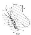
- FIG. 3shows in a greatly schematized form a longitudinal section through a femur in which a ligament transplant is being inserted, with the aid of anchoring elements according to the invention
- FIG. 4shows a greatly enlarged cross section along the line IV—IV in FIG. 3 after anchoring the ligament transplant
- FIG. 5shows a representation comparable to the section of FIG. 4 when a differently shaped ligament transplant is used.
- FIGS. 1 and 2An anchoring element according to the invention, represented in FIGS. 1 and 2 , is provided overall with the reference numeral 10 .
- the anchoring element 10has a roughly rod-shaped or cylindrical body 12 , which is joined to a pulling thread 14 .
- the outer side of the body 12is closed off by a sheath 16 , which has a mesh-like structure 18 .
- Mesh-likemeans that there are numerous openings in the sheath 16 , making it possible for example for a fluid to penetrate from the outside into the space inside the sheath 16 .
- Accommodated in the sheath 16is a material 20 in the form of numerous particles in the form of cubes 22 of spongiosa. The cubes do not have to have the exact form of a cube and are approximately 0.5–3 mm in size.
- the sheath 16In the unwound state, the sheath 16 has an approximately rectangular shape and a quantity of the cubes 22 were placed approximately centrally onto this shape.
- the cubes 22may result from a drilling process for preparing a bore channel in a bone, i.e. the femur 30 shown in FIG. 3 .
- the core of bone material drilled outis divided into the cubes 22 .
- two opposite sideswere folded over and placed against each other and the body sewn by means of an approximately U-shaped seam 24 to form a closed body 12 or quill. Accordingly, the sheath 16 encloses the plastically deformable mass of cubes 22 of spongiosa accommodated therein.
- the sheath 16is, furthermore, joined to a pulling thread 14 , which has simply been inserted through the body 12 by piercing with a needle.
- the pulling thread 14is tied together at its outer ends, consequently joined to form a loop.
- FIG. 3only the femur of the knee joint is represented.
- the ligament transplant 38 indicated there in the form of a cruciate ligament replacementalso extends as far as the tibia, as known per se in the case of this surgical technique.
- a continuous channel 32which has a first portion 34 of a larger diameter which is followed by a second portion 36 of a smaller diameter, has been drilled into the femur in an outwardly inclined manner, from the side of the joint.
- the second portion 36opens out on the outer side of the femur, the first portion 34 opens out in the region of the joint.
- the ligament transplant 38 usedcomprises a semitendinosus tendon, which has been placed in such a way as to produce two strands 44 and 45 running alongside each other, which are joined together via a loop 42 .
- this cruciate ligament replacementis pulled into the first portion 34 of larger diameter of the channel 32 .
- the loop 42is joined to a number of threads 46 , which were previously threaded through the channel 32 .
- the surgeoncan pull on the corresponding threads 46 and thereby pull the loop 42 into the channel and position it.
- a first anchoring element 10has already been pulled into the first portion 34 of larger diameter, its pulling thread 14 likewise having been threaded through the channel 32 in advance and protruding out via the mouth of the second portion 36 of smaller diameter.
- the body of the anchoring element 10can be brought into the intermediate space 48 between the inner wall 50 of the portion 34 of larger diameter and the outer side 52 of the ligament transplant 38 , as can be seen in FIG. 4 at the upper end.
- the body 12 of the anchoring element 10assumes the shape of this intermediate space 48 , that is approximately the shape of a double sickle.
- the ligament transplant 38is indicated as twisted somewhat, in order to show its double-stranded nature.
- the second anchoring element 10 ′can then also be pulled in, by pulling on its pulling thread 14 ′, which has likewise been threaded through the channel 32 in advance, as indicated in FIG. 3 by the arrow 55 .
- the anchoring elements 10 , 10 ′almost completely fill the intermediate space 48 present on both sides of the double-stranded ligament transplant 38 , so that an exact anchored fit is created.
- sheath 16has a perforated structure 18 means that it is possible for appropriate fluids that promote the growth of corresponding osteoblasts to enter, so that intimate growing together of the transplant 38 and the bone 30 can take place as soon as possible in the region of the anchoring elements 10 and 10 ′.
- the entire space inside the channelis filled by substances taken from the same patient, that is by the patient's own semitendinosus tendon and own spongiosa cubes, so that a particularly favorable inward growth is possible without reactions of rejection.
- a bioresorbable materialis used for the sheath 16 , for example a biodegradable VICRYL mesh, this is biodegraded as soon as possible, so that only materials taken from the same body are present.
- the pulling threads 14 , 14 ′ of the anchoring elements 10 and 10 ′not only facilitate handling when introducing or pulling in the anchoring elements 10 , 10 ′ but also provide fixing, at least until the respective anchoring element 10 , 10 ′ has grown in.
- an appropriate circular channel 32 ′has equally been drilled into a bone 30 ′ and a ligament transplant 58 , which originally has a somewhat elongate rectangular cross section, for example a patellar tendon taken from the same body, has been inserted.
- the corresponding anchoring element 60is formed like the anchoring elements 10 , 10 ′ and can then fill the corresponding intermediate space between the channel 32 ′ and the ligament implant 58 on account of its plastic deformability, as can be seen from the sectional representation.
- corresponding markersmay be introduced into the anchoring elements for monitoring purposes, whether in the mesh or between the cubes of spongy material, in order to allow the actual operating site nevertheless to be radiologically picked up.
- the surgical techniques described abovewere described in conjunction with a cruciate ligament replacement, but may equally be used also in the case of other surgical techniques for other joints, whether in the shoulder joint, in the ankle joint or other joints.
Landscapes
- Health & Medical Sciences (AREA)
- Orthopedic Medicine & Surgery (AREA)
- Rehabilitation Therapy (AREA)
- Rheumatology (AREA)
- Cardiology (AREA)
- Oral & Maxillofacial Surgery (AREA)
- Transplantation (AREA)
- Engineering & Computer Science (AREA)
- Biomedical Technology (AREA)
- Heart & Thoracic Surgery (AREA)
- Vascular Medicine (AREA)
- Life Sciences & Earth Sciences (AREA)
- Animal Behavior & Ethology (AREA)
- General Health & Medical Sciences (AREA)
- Public Health (AREA)
- Veterinary Medicine (AREA)
- Surgical Instruments (AREA)
- Prostheses (AREA)
Abstract
Description
Claims (12)
Applications Claiming Priority (2)
| Application Number | Priority Date | Filing Date | Title |
|---|---|---|---|
| EP02002861.9 | 2002-02-08 | ||
| EP02002861AEP1334702B1 (en) | 2002-02-08 | 2002-02-08 | Anchor element to anchor a ligament transplant |
Publications (2)
| Publication Number | Publication Date |
|---|---|
| US20050004670A1 US20050004670A1 (en) | 2005-01-06 |
| US7001390B2true US7001390B2 (en) | 2006-02-21 |
Family
ID=27589092
Family Applications (1)
| Application Number | Title | Priority Date | Filing Date |
|---|---|---|---|
| US10/361,741Expired - Fee RelatedUS7001390B2 (en) | 2002-02-08 | 2003-02-10 | Anchoring element for anchoring a ligament transplant |
Country Status (3)
| Country | Link |
|---|---|
| US (1) | US7001390B2 (en) |
| EP (1) | EP1334702B1 (en) |
| DE (1) | DE50200594D1 (en) |
Cited By (21)
| Publication number | Priority date | Publication date | Assignee | Title |
|---|---|---|---|---|
| US20070098756A1 (en)* | 2005-11-01 | 2007-05-03 | Keyvan Behnam | Bone Matrix Compositions and Methods |
| US20070154563A1 (en)* | 2003-12-31 | 2007-07-05 | Keyvan Behnam | Bone matrix compositions and methods |
| US20070231788A1 (en)* | 2003-12-31 | 2007-10-04 | Keyvan Behnam | Method for In Vitro Assay of Demineralized Bone Matrix |
| US20090087471A1 (en)* | 2007-06-15 | 2009-04-02 | Shimp Lawrence A | Method of treating tissue |
| US20090130173A1 (en)* | 2007-06-15 | 2009-05-21 | Keyvan Behnam | Bone matrix compositions and methods |
| US20090155378A1 (en)* | 2003-12-31 | 2009-06-18 | Keyvan Behnam | Osteoinductive demineralized cancellous bone |
| US20090157087A1 (en)* | 2007-07-10 | 2009-06-18 | Guobao Wei | Delivery system attachment |
| US20090220605A1 (en)* | 2007-06-15 | 2009-09-03 | Osteotech | Bone matrix compositions having nanoscale textured surfaces |
| US20090226523A1 (en)* | 2007-10-19 | 2009-09-10 | Keyvan Behnam | Demineralized bone matrix compositions and methods |
| US20090242081A1 (en)* | 2008-03-26 | 2009-10-01 | Richard Bauer | Aluminum Treatment Composition |
| US20100121448A1 (en)* | 2001-03-13 | 2010-05-13 | Depuy Mitek, Inc. | Method and apparatus for fixing a graft in a bone tunnel |
| US20100204699A1 (en)* | 2009-02-12 | 2010-08-12 | Guobao Wei | Delivery system cartridge |
| US20100249930A1 (en)* | 2009-03-31 | 2010-09-30 | Medicinelodge, Inc. Dba Imds Co-Innovation | Double bundle acl repair |
| US20110054408A1 (en)* | 2007-07-10 | 2011-03-03 | Guobao Wei | Delivery systems, devices, tools, and methods of use |
| US20130204367A1 (en)* | 2012-02-02 | 2013-08-08 | Smith & Nephew, Inc. | Implantable biologic holder |
| US8900620B2 (en) | 2005-10-13 | 2014-12-02 | DePuy Synthes Products, LLC | Drug-impregnated encasement |
| US8968402B2 (en) | 2011-10-18 | 2015-03-03 | Arthrocare Corporation | ACL implants, instruments, and methods |
| US9232939B2 (en) | 2012-09-11 | 2016-01-12 | Biomet Sports Medicine, Llc | Flexible planar member for tissue fixation |
| US9381683B2 (en) | 2011-12-28 | 2016-07-05 | DePuy Synthes Products, Inc. | Films and methods of manufacture |
| US20190143001A1 (en)* | 2017-11-15 | 2019-05-16 | De Novo Orthopedics Inc. | Bioinductive patch |
| US10500304B2 (en) | 2013-06-21 | 2019-12-10 | DePuy Synthes Products, Inc. | Films and methods of manufacture |
Families Citing this family (64)
| Publication number | Priority date | Publication date | Assignee | Title |
|---|---|---|---|---|
| US6893462B2 (en)* | 2000-01-11 | 2005-05-17 | Regeneration Technologies, Inc. | Soft and calcified tissue implants |
| US8512376B2 (en) | 2002-08-30 | 2013-08-20 | Arthrex, Inc. | Method and apparatus for internal fixation of an acromioclavicular joint dislocation of the shoulder |
| US7909851B2 (en) | 2006-02-03 | 2011-03-22 | Biomet Sports Medicine, Llc | Soft tissue repair device and associated methods |
| US8298262B2 (en) | 2006-02-03 | 2012-10-30 | Biomet Sports Medicine, Llc | Method for tissue fixation |
| US8137382B2 (en) | 2004-11-05 | 2012-03-20 | Biomet Sports Medicine, Llc | Method and apparatus for coupling anatomical features |
| US7749250B2 (en) | 2006-02-03 | 2010-07-06 | Biomet Sports Medicine, Llc | Soft tissue repair assembly and associated method |
| US7905904B2 (en) | 2006-02-03 | 2011-03-15 | Biomet Sports Medicine, Llc | Soft tissue repair device and associated methods |
| US8088130B2 (en) | 2006-02-03 | 2012-01-03 | Biomet Sports Medicine, Llc | Method and apparatus for coupling soft tissue to a bone |
| US8118836B2 (en) | 2004-11-05 | 2012-02-21 | Biomet Sports Medicine, Llc | Method and apparatus for coupling soft tissue to a bone |
| US8303604B2 (en) | 2004-11-05 | 2012-11-06 | Biomet Sports Medicine, Llc | Soft tissue repair device and method |
| US7658751B2 (en) | 2006-09-29 | 2010-02-09 | Biomet Sports Medicine, Llc | Method for implanting soft tissue |
| US9017381B2 (en) | 2007-04-10 | 2015-04-28 | Biomet Sports Medicine, Llc | Adjustable knotless loops |
| US8128658B2 (en) | 2004-11-05 | 2012-03-06 | Biomet Sports Medicine, Llc | Method and apparatus for coupling soft tissue to bone |
| US8361113B2 (en) | 2006-02-03 | 2013-01-29 | Biomet Sports Medicine, Llc | Method and apparatus for coupling soft tissue to a bone |
| US9801708B2 (en) | 2004-11-05 | 2017-10-31 | Biomet Sports Medicine, Llc | Method and apparatus for coupling soft tissue to a bone |
| US8652171B2 (en) | 2006-02-03 | 2014-02-18 | Biomet Sports Medicine, Llc | Method and apparatus for soft tissue fixation |
| US8562647B2 (en) | 2006-09-29 | 2013-10-22 | Biomet Sports Medicine, Llc | Method and apparatus for securing soft tissue to bone |
| US8652172B2 (en) | 2006-02-03 | 2014-02-18 | Biomet Sports Medicine, Llc | Flexible anchors for tissue fixation |
| US9078644B2 (en) | 2006-09-29 | 2015-07-14 | Biomet Sports Medicine, Llc | Fracture fixation device |
| US8801783B2 (en) | 2006-09-29 | 2014-08-12 | Biomet Sports Medicine, Llc | Prosthetic ligament system for knee joint |
| US9538998B2 (en) | 2006-02-03 | 2017-01-10 | Biomet Sports Medicine, Llc | Method and apparatus for fracture fixation |
| US9468433B2 (en) | 2006-02-03 | 2016-10-18 | Biomet Sports Medicine, Llc | Method and apparatus for forming a self-locking adjustable loop |
| US11259792B2 (en) | 2006-02-03 | 2022-03-01 | Biomet Sports Medicine, Llc | Method and apparatus for coupling anatomical features |
| US9149267B2 (en) | 2006-02-03 | 2015-10-06 | Biomet Sports Medicine, Llc | Method and apparatus for coupling soft tissue to a bone |
| US10517587B2 (en) | 2006-02-03 | 2019-12-31 | Biomet Sports Medicine, Llc | Method and apparatus for forming a self-locking adjustable loop |
| US8562645B2 (en) | 2006-09-29 | 2013-10-22 | Biomet Sports Medicine, Llc | Method and apparatus for forming a self-locking adjustable loop |
| US9408599B2 (en) | 2006-02-03 | 2016-08-09 | Biomet Sports Medicine, Llc | Method and apparatus for coupling soft tissue to a bone |
| US8968364B2 (en) | 2006-02-03 | 2015-03-03 | Biomet Sports Medicine, Llc | Method and apparatus for fixation of an ACL graft |
| US11311287B2 (en) | 2006-02-03 | 2022-04-26 | Biomet Sports Medicine, Llc | Method for tissue fixation |
| US8597327B2 (en) | 2006-02-03 | 2013-12-03 | Biomet Manufacturing, Llc | Method and apparatus for sternal closure |
| US20080027443A1 (en)* | 2006-07-26 | 2008-01-31 | Lambert Systms, L.L.C. | Biocompatible Anchoring Device For A Soft Tissue Graft, Method Of Making And Method Of Using |
| US8500818B2 (en) | 2006-09-29 | 2013-08-06 | Biomet Manufacturing, Llc | Knee prosthesis assembly with ligament link |
| US9918826B2 (en) | 2006-09-29 | 2018-03-20 | Biomet Sports Medicine, Llc | Scaffold for spring ligament repair |
| US8672969B2 (en) | 2006-09-29 | 2014-03-18 | Biomet Sports Medicine, Llc | Fracture fixation device |
| US11259794B2 (en) | 2006-09-29 | 2022-03-01 | Biomet Sports Medicine, Llc | Method for implanting soft tissue |
| US12245759B2 (en) | 2008-08-22 | 2025-03-11 | Biomet Sports Medicine, Llc | Method and apparatus for coupling soft tissue to bone |
| US12419632B2 (en) | 2008-08-22 | 2025-09-23 | Biomet Sports Medicine, Llc | Method and apparatus for coupling anatomical features |
| US8460379B2 (en) | 2009-03-31 | 2013-06-11 | Arthrex, Inc. | Adjustable suture button construct and methods of tissue reconstruction |
| US8439976B2 (en)* | 2009-03-31 | 2013-05-14 | Arthrex, Inc. | Integrated adjustable button-suture-graft construct with two fixation devices |
| US12096928B2 (en) | 2009-05-29 | 2024-09-24 | Biomet Sports Medicine, Llc | Method and apparatus for coupling soft tissue to a bone |
| US9307977B2 (en) | 2010-11-04 | 2016-04-12 | Conmed Corporation | Method and apparatus for securing an object to bone, including the provision and use of a novel suture assembly for securing suture to bone |
| US9307978B2 (en) | 2010-11-04 | 2016-04-12 | Linvatec Corporation | Method and apparatus for securing an object to bone, including the provision and use of a novel suture assembly for securing an object to bone |
| EP2455002B1 (en) | 2010-11-17 | 2019-04-03 | Arthrex, Inc. | Adjustable suture-button construct for ankle syndesmosis repair |
| EP2455001B1 (en) | 2010-11-17 | 2020-07-22 | Arthrex, Inc. | Adjustable suture-button constructs for ligament reconstruction |
| EP2455040B1 (en) | 2010-11-17 | 2015-03-04 | Arthrex, Inc. | Adjustable suture-button construct for knotless stabilization of cranial cruciate deficient ligament stifle |
| EP2675363B1 (en) | 2011-02-16 | 2018-05-23 | Linvatec Corporation | Apparatus for securing an object to bone |
| US12329373B2 (en) | 2011-05-02 | 2025-06-17 | Biomet Sports Medicine, Llc | Method and apparatus for soft tissue fixation |
| US9301745B2 (en) | 2011-07-21 | 2016-04-05 | Arthrex, Inc. | Knotless suture constructs |
| US9332979B2 (en) | 2011-07-22 | 2016-05-10 | Arthrex, Inc. | Tensionable knotless acromioclavicular repairs and constructs |
| US9107653B2 (en) | 2011-09-22 | 2015-08-18 | Arthrex, Inc. | Tensionable knotless anchors with splice and methods of tissue repair |
| US10245016B2 (en) | 2011-10-12 | 2019-04-02 | Arthrex, Inc. | Adjustable self-locking loop constructs for tissue repairs and reconstructions |
| US9357991B2 (en) | 2011-11-03 | 2016-06-07 | Biomet Sports Medicine, Llc | Method and apparatus for stitching tendons |
| US9381013B2 (en) | 2011-11-10 | 2016-07-05 | Biomet Sports Medicine, Llc | Method for coupling soft tissue to a bone |
| US9314241B2 (en) | 2011-11-10 | 2016-04-19 | Biomet Sports Medicine, Llc | Apparatus for coupling soft tissue to a bone |
| EP2601894B1 (en) | 2011-12-09 | 2018-08-29 | Arthrex, Inc. | Tensionable knotless anchor systems |
| GB2502959A (en)* | 2012-06-11 | 2013-12-18 | Xiros Ltd | Synthetic ligament assembly |
| US9737292B2 (en) | 2012-06-22 | 2017-08-22 | Arthrex, Inc. | Knotless suture anchors and methods of tissue repair |
| US9757119B2 (en) | 2013-03-08 | 2017-09-12 | Biomet Sports Medicine, Llc | Visual aid for identifying suture limbs arthroscopically |
| US9918827B2 (en) | 2013-03-14 | 2018-03-20 | Biomet Sports Medicine, Llc | Scaffold for spring ligament repair |
| EP3052203A4 (en) | 2013-09-30 | 2017-08-23 | Silk Therapeutics Inc. | Silk protein fragment compositions and articles manufactured therefrom |
| EP3322434B1 (en) | 2015-07-14 | 2024-12-11 | Evolved by Nature, Inc. | Silk performance apparel and products and methods of preparing the same |
| US10265060B2 (en) | 2015-08-20 | 2019-04-23 | Arthrex, Inc. | Tensionable constructs with multi-limb locking mechanism through single splice and methods of tissue repair |
| US10335136B2 (en) | 2015-08-20 | 2019-07-02 | Arthrex, Inc. | Tensionable constructs with multi-limb locking mechanism through single splice and methods of tissue repair |
| US11390988B2 (en) | 2017-09-27 | 2022-07-19 | Evolved By Nature, Inc. | Silk coated fabrics and products and methods of preparing the same |
Citations (10)
| Publication number | Priority date | Publication date | Assignee | Title |
|---|---|---|---|---|
| US4755184A (en)* | 1986-01-09 | 1988-07-05 | Mark Silverberg | Bone augmentation implant |
| WO1993015694A1 (en) | 1992-02-14 | 1993-08-19 | Board Of Regents, The University Of Texas System | Multi-phase bioerodible implant/carrier and method of manufacturing and using same |
| EP0642773A1 (en) | 1993-09-14 | 1995-03-15 | Lanny L. Johnson | Biological replacement ligament |
| US5501706A (en) | 1994-11-29 | 1996-03-26 | Wildflower Communications, Inc. | Medical implant structure and method for using the same |
| WO1998037835A1 (en) | 1997-02-25 | 1998-09-03 | Philip Stuart Esnouf | Surgical aid for connective tissue grafting and method for employing same |
| US5899938A (en)* | 1996-11-27 | 1999-05-04 | Joseph H. Sklar | Graft ligament anchor and method for attaching a graft ligament to a bone |
| WO1999044544A1 (en) | 1998-03-02 | 1999-09-10 | Bionx Implants Oy | Improved bioabsorbable bone block fixation implant |
| DE19851152A1 (en) | 1998-11-06 | 2000-05-11 | Storz Karl Gmbh & Co Kg | Instruments for implanting a cruciate ligament replacement in a knee joint |
| WO2001082989A1 (en) | 2000-05-04 | 2001-11-08 | Phillips Plastics Corporation | Packable ceramic beads for bone repair |
| US6746483B1 (en)* | 2000-03-16 | 2004-06-08 | Smith & Nephew, Inc. | Sheaths for implantable fixation devices |
Family Cites Families (1)
| Publication number | Priority date | Publication date | Assignee | Title |
|---|---|---|---|---|
| ES2185651T3 (en) | 1993-06-04 | 2003-05-01 | Smith & Nephew Inc | SURGICAL SCREW AND WASHER. |
- 2002
- 2002-02-08EPEP02002861Apatent/EP1334702B1/ennot_activeExpired - Lifetime
- 2002-02-08DEDE50200594Tpatent/DE50200594D1/ennot_activeExpired - Lifetime
- 2003
- 2003-02-10USUS10/361,741patent/US7001390B2/ennot_activeExpired - Fee Related
Patent Citations (11)
| Publication number | Priority date | Publication date | Assignee | Title |
|---|---|---|---|---|
| US4755184A (en)* | 1986-01-09 | 1988-07-05 | Mark Silverberg | Bone augmentation implant |
| WO1993015694A1 (en) | 1992-02-14 | 1993-08-19 | Board Of Regents, The University Of Texas System | Multi-phase bioerodible implant/carrier and method of manufacturing and using same |
| EP0642773A1 (en) | 1993-09-14 | 1995-03-15 | Lanny L. Johnson | Biological replacement ligament |
| US5501706A (en) | 1994-11-29 | 1996-03-26 | Wildflower Communications, Inc. | Medical implant structure and method for using the same |
| US5899938A (en)* | 1996-11-27 | 1999-05-04 | Joseph H. Sklar | Graft ligament anchor and method for attaching a graft ligament to a bone |
| WO1998037835A1 (en) | 1997-02-25 | 1998-09-03 | Philip Stuart Esnouf | Surgical aid for connective tissue grafting and method for employing same |
| WO1999044544A1 (en) | 1998-03-02 | 1999-09-10 | Bionx Implants Oy | Improved bioabsorbable bone block fixation implant |
| DE19851152A1 (en) | 1998-11-06 | 2000-05-11 | Storz Karl Gmbh & Co Kg | Instruments for implanting a cruciate ligament replacement in a knee joint |
| US6267767B1 (en)* | 1998-11-06 | 2001-07-31 | Karl Storz Gmbh & Co. Kg | Instrumentarium and method for implanting a cruciate ligament replacement in a knee joint |
| US6746483B1 (en)* | 2000-03-16 | 2004-06-08 | Smith & Nephew, Inc. | Sheaths for implantable fixation devices |
| WO2001082989A1 (en) | 2000-05-04 | 2001-11-08 | Phillips Plastics Corporation | Packable ceramic beads for bone repair |
Cited By (66)
| Publication number | Priority date | Publication date | Assignee | Title |
|---|---|---|---|---|
| US20100121448A1 (en)* | 2001-03-13 | 2010-05-13 | Depuy Mitek, Inc. | Method and apparatus for fixing a graft in a bone tunnel |
| US8591580B2 (en) | 2001-03-13 | 2013-11-26 | Depuy Mitek, Llc | Folded ligament graft |
| US8226716B2 (en)* | 2001-03-13 | 2012-07-24 | Depuy Mitek, Inc. | Method and apparatus for fixing a graft in a bone tunnel |
| US9314332B2 (en) | 2001-03-13 | 2016-04-19 | Depuy Mitek, Llc | Method and apparatus for fixing a graft in a bone tunnel |
| US20070154563A1 (en)* | 2003-12-31 | 2007-07-05 | Keyvan Behnam | Bone matrix compositions and methods |
| US20070231788A1 (en)* | 2003-12-31 | 2007-10-04 | Keyvan Behnam | Method for In Vitro Assay of Demineralized Bone Matrix |
| US8734525B2 (en) | 2003-12-31 | 2014-05-27 | Warsaw Orthopedic, Inc. | Osteoinductive demineralized cancellous bone |
| US8328876B2 (en) | 2003-12-31 | 2012-12-11 | Warsaw Orthopedic, Inc. | Bone matrix compositions and methods |
| US20090155378A1 (en)* | 2003-12-31 | 2009-06-18 | Keyvan Behnam | Osteoinductive demineralized cancellous bone |
| US9034358B2 (en) | 2003-12-31 | 2015-05-19 | Warsaw Orthopedic, Inc. | Bone matrix compositions and methods |
| US9415136B2 (en) | 2003-12-31 | 2016-08-16 | Warsaw Orthopedic, Inc. | Osteoinductive demineralized cancellous bone |
| US10814112B2 (en) | 2005-10-13 | 2020-10-27 | DePuy Synthes Products, Inc. | Drug-impregnated encasement |
| US9579260B2 (en) | 2005-10-13 | 2017-02-28 | DePuy Synthes Products, Inc. | Drug-impregnated encasement |
| US8900620B2 (en) | 2005-10-13 | 2014-12-02 | DePuy Synthes Products, LLC | Drug-impregnated encasement |
| US8992965B2 (en) | 2005-11-01 | 2015-03-31 | Warsaw Orthopedic, Inc. | Bone matrix compositions and methods |
| US8911759B2 (en) | 2005-11-01 | 2014-12-16 | Warsaw Orthopedic, Inc. | Bone matrix compositions and methods |
| US20070098756A1 (en)* | 2005-11-01 | 2007-05-03 | Keyvan Behnam | Bone Matrix Compositions and Methods |
| US10328179B2 (en) | 2005-11-01 | 2019-06-25 | Warsaw Orthopedic, Inc. | Bone matrix compositions and methods |
| US20070110820A1 (en)* | 2005-11-01 | 2007-05-17 | Keyvan Behnam | Bone Matrix Compositions and Methods |
| US20090220605A1 (en)* | 2007-06-15 | 2009-09-03 | Osteotech | Bone matrix compositions having nanoscale textured surfaces |
| US9717822B2 (en) | 2007-06-15 | 2017-08-01 | Warsaw Orthopedic, Inc. | Bone matrix compositions and methods |
| US8642061B2 (en) | 2007-06-15 | 2014-02-04 | Warsaw Orthopedic, Inc. | Method of treating bone tissue |
| US20090130173A1 (en)* | 2007-06-15 | 2009-05-21 | Keyvan Behnam | Bone matrix compositions and methods |
| US8357384B2 (en) | 2007-06-15 | 2013-01-22 | Warsaw Orthopedic, Inc. | Bone matrix compositions and methods |
| US10357511B2 (en) | 2007-06-15 | 2019-07-23 | Warsaw Orthopedic, Inc. | Bone matrix compositions and methods |
| US10220115B2 (en) | 2007-06-15 | 2019-03-05 | Warsaw Orthopedic, Inc. | Bone matrix compositions having nanoscale textured surfaces |
| US20090087471A1 (en)* | 2007-06-15 | 2009-04-02 | Shimp Lawrence A | Method of treating tissue |
| US9554920B2 (en) | 2007-06-15 | 2017-01-31 | Warsaw Orthopedic, Inc. | Bone matrix compositions having nanoscale textured surfaces |
| US9492278B2 (en) | 2007-07-10 | 2016-11-15 | Warsaw Orthopedic, Inc. | Delivery system |
| US10028837B2 (en) | 2007-07-10 | 2018-07-24 | Warsaw Orthopedic, Inc. | Delivery system attachment |
| US20090157087A1 (en)* | 2007-07-10 | 2009-06-18 | Guobao Wei | Delivery system attachment |
| US20090192474A1 (en)* | 2007-07-10 | 2009-07-30 | Guobao Wei | Delivery system |
| US9358113B2 (en) | 2007-07-10 | 2016-06-07 | Warsaw Orthopedic, Inc. | Delivery system |
| US20090234277A1 (en)* | 2007-07-10 | 2009-09-17 | Guobao Wei | Delivery system |
| US9333082B2 (en) | 2007-07-10 | 2016-05-10 | Warsaw Orthopedic, Inc. | Delivery system attachment |
| US20110054408A1 (en)* | 2007-07-10 | 2011-03-03 | Guobao Wei | Delivery systems, devices, tools, and methods of use |
| US8435566B2 (en) | 2007-10-19 | 2013-05-07 | Warsaw Orthopedic, Inc. | Demineralized bone matrix compositions and methods |
| US20090226523A1 (en)* | 2007-10-19 | 2009-09-10 | Keyvan Behnam | Demineralized bone matrix compositions and methods |
| US8202539B2 (en) | 2007-10-19 | 2012-06-19 | Warsaw Orthopedic, Inc. | Demineralized bone matrix compositions and methods |
| US20090242081A1 (en)* | 2008-03-26 | 2009-10-01 | Richard Bauer | Aluminum Treatment Composition |
| US9220598B2 (en) | 2009-02-12 | 2015-12-29 | Warsaw Orthopedic, Inc. | Delivery systems, tools, and methods of use |
| US20100203155A1 (en)* | 2009-02-12 | 2010-08-12 | Guobao Wei | Segmented delivery system |
| US10098681B2 (en) | 2009-02-12 | 2018-10-16 | Warsaw Orthopedic, Inc. | Segmented delivery system |
| US9101475B2 (en)* | 2009-02-12 | 2015-08-11 | Warsaw Orthopedic, Inc. | Segmented delivery system |
| US9011537B2 (en) | 2009-02-12 | 2015-04-21 | Warsaw Orthopedic, Inc. | Delivery system cartridge |
| US20100204699A1 (en)* | 2009-02-12 | 2010-08-12 | Guobao Wei | Delivery system cartridge |
| US20100268232A1 (en)* | 2009-02-12 | 2010-10-21 | Osteotech, Inc. | Delivery systems, tools, and methods of use |
| US20100249930A1 (en)* | 2009-03-31 | 2010-09-30 | Medicinelodge, Inc. Dba Imds Co-Innovation | Double bundle acl repair |
| US20110137416A1 (en)* | 2009-03-31 | 2011-06-09 | Thomas H. Myers | Double bundle acl repair |
| US8617241B2 (en)* | 2009-03-31 | 2013-12-31 | Imds Corporation | Double bundle ACL repair |
| US8579975B2 (en)* | 2009-03-31 | 2013-11-12 | Imds Corporation | Double bundle ACL repair |
| US9549811B2 (en) | 2009-03-31 | 2017-01-24 | Imds Llc | Double bundle ACL repair |
| US9216079B2 (en) | 2009-03-31 | 2015-12-22 | Imds Llc | Double bundle ACL repair |
| US8968402B2 (en) | 2011-10-18 | 2015-03-03 | Arthrocare Corporation | ACL implants, instruments, and methods |
| US9381683B2 (en) | 2011-12-28 | 2016-07-05 | DePuy Synthes Products, Inc. | Films and methods of manufacture |
| US10617653B2 (en) | 2011-12-28 | 2020-04-14 | DePuy Synthes Products, Inc. | Films and methods of manufacture |
| US9913710B2 (en) | 2012-02-02 | 2018-03-13 | Smith & Nephew, Inc. | Implantable biologic holder |
| US20130204367A1 (en)* | 2012-02-02 | 2013-08-08 | Smith & Nephew, Inc. | Implantable biologic holder |
| US9204959B2 (en)* | 2012-02-02 | 2015-12-08 | Smith & Nephew, Inc. | Implantable biologic holder |
| US10130355B2 (en) | 2012-09-11 | 2018-11-20 | Biomet Sports Medicine, Llc | Flexible planar member for tissue fixation |
| US9232939B2 (en) | 2012-09-11 | 2016-01-12 | Biomet Sports Medicine, Llc | Flexible planar member for tissue fixation |
| US10500304B2 (en) | 2013-06-21 | 2019-12-10 | DePuy Synthes Products, Inc. | Films and methods of manufacture |
| US20190143001A1 (en)* | 2017-11-15 | 2019-05-16 | De Novo Orthopedics Inc. | Bioinductive patch |
| US20190142997A1 (en)* | 2017-11-15 | 2019-05-16 | De Novo Orthopedics Inc. | Method for manufacturing bioinductive patch |
| US10881762B2 (en)* | 2017-11-15 | 2021-01-05 | De Novo Orthopedics Inc. | Method for manufacturing bioinductive patch |
| US10912867B2 (en)* | 2017-11-15 | 2021-02-09 | De Novo Orthopedics Inc. | Bioinductive patch |
Also Published As
| Publication number | Publication date |
|---|---|
| DE50200594D1 (en) | 2004-08-12 |
| EP1334702A1 (en) | 2003-08-13 |
| US20050004670A1 (en) | 2005-01-06 |
| EP1334702B1 (en) | 2004-07-07 |
Similar Documents
| Publication | Publication Date | Title |
|---|---|---|
| US7001390B2 (en) | Anchoring element for anchoring a ligament transplant | |
| US8696748B2 (en) | Sheaths for implantable fixation devices | |
| US6562071B2 (en) | Fixation anchor | |
| EP0705567B1 (en) | Expanding suture anchor | |
| EP1169979B1 (en) | Use of an adhesive substance for the manufacture of a bone adhesive for fixing a bone plug in a bone tunnel | |
| RU2567603C2 (en) | Method of fastening tissue or respective prosthesis in hole made in human or animal bone and fastening device intended for method realisation | |
| US20070055255A1 (en) | Bioabsorbable Endosteal Fixation Device and Method of Use | |
| AU2001243646A1 (en) | Sheaths for implantable fixation devices | |
| US20040117014A1 (en) | Prosthetic implant assembly | |
| JP2001505107A (en) | Apparatus and method for securing a self or artificial tendon graft to bone | |
| EP2809268B1 (en) | Implantable biologic holder | |
| JP2022548615A (en) | An implant comprising a first set and a second set of pillars for attaching a tendon or ligament to hard tissue | |
| AU2005202598B2 (en) | Sheaths for implantable fixation devices |
Legal Events
| Date | Code | Title | Description |
|---|---|---|---|
| AS | Assignment | Owner name:KARL STORZ GMBH & CO. KG, GERMANY Free format text:ASSIGNMENT OF ASSIGNORS INTEREST;ASSIGNOR:GEBHARDT, ULLRICH;REEL/FRAME:014120/0589 Effective date:20030324 | |
| AS | Assignment | Owner name:KARL STORZ GMBH & CO. KG, A GERMANY LIMITED PARTNE Free format text:ASSIGNMENT OF ASSIGNORS INTEREST;ASSIGNOR:TIMMESMANNS, ANDRE;REEL/FRAME:014209/0655 Effective date:20000205 | |
| FEPP | Fee payment procedure | Free format text:PAYOR NUMBER ASSIGNED (ORIGINAL EVENT CODE: ASPN); ENTITY STATUS OF PATENT OWNER: LARGE ENTITY | |
| FEPP | Fee payment procedure | Free format text:PAYER NUMBER DE-ASSIGNED (ORIGINAL EVENT CODE: RMPN); ENTITY STATUS OF PATENT OWNER: LARGE ENTITY Free format text:PAYOR NUMBER ASSIGNED (ORIGINAL EVENT CODE: ASPN); ENTITY STATUS OF PATENT OWNER: LARGE ENTITY | |
| FEPP | Fee payment procedure | Free format text:PAYER NUMBER DE-ASSIGNED (ORIGINAL EVENT CODE: RMPN); ENTITY STATUS OF PATENT OWNER: LARGE ENTITY Free format text:PAYOR NUMBER ASSIGNED (ORIGINAL EVENT CODE: ASPN); ENTITY STATUS OF PATENT OWNER: LARGE ENTITY | |
| FPAY | Fee payment | Year of fee payment:4 | |
| REMI | Maintenance fee reminder mailed | ||
| LAPS | Lapse for failure to pay maintenance fees | ||
| STCH | Information on status: patent discontinuation | Free format text:PATENT EXPIRED DUE TO NONPAYMENT OF MAINTENANCE FEES UNDER 37 CFR 1.362 | |
| FP | Lapsed due to failure to pay maintenance fee | Effective date:20140221 |