US7001388B2 - System for stabilization of fractures of convex articular bone surfaces including subchondral support structure - Google Patents
System for stabilization of fractures of convex articular bone surfaces including subchondral support structureDownload PDFInfo
- Publication number
- US7001388B2 US7001388B2US11/040,734US4073405AUS7001388B2US 7001388 B2US7001388 B2US 7001388B2US 4073405 AUS4073405 AUS 4073405AUS 7001388 B2US7001388 B2US 7001388B2
- Authority
- US
- United States
- Prior art keywords
- post
- peg
- holes
- hole
- fracture
- Prior art date
- Legal status (The legal status is an assumption and is not a legal conclusion. Google has not performed a legal analysis and makes no representation as to the accuracy of the status listed.)
- Expired - Lifetime
Links
Images


Classifications
- A—HUMAN NECESSITIES
- A61—MEDICAL OR VETERINARY SCIENCE; HYGIENE
- A61B—DIAGNOSIS; SURGERY; IDENTIFICATION
- A61B17/00—Surgical instruments, devices or methods
- A61B17/56—Surgical instruments or methods for treatment of bones or joints; Devices specially adapted therefor
- A61B17/58—Surgical instruments or methods for treatment of bones or joints; Devices specially adapted therefor for osteosynthesis, e.g. bone plates, screws or setting implements
- A61B17/68—Internal fixation devices, including fasteners and spinal fixators, even if a part thereof projects from the skin
- A61B17/80—Cortical plates, i.e. bone plates; Instruments for holding or positioning cortical plates, or for compressing bones attached to cortical plates
- A61B17/8061—Cortical plates, i.e. bone plates; Instruments for holding or positioning cortical plates, or for compressing bones attached to cortical plates specially adapted for particular bones
- A—HUMAN NECESSITIES
- A61—MEDICAL OR VETERINARY SCIENCE; HYGIENE
- A61B—DIAGNOSIS; SURGERY; IDENTIFICATION
- A61B17/00—Surgical instruments, devices or methods
- A61B17/56—Surgical instruments or methods for treatment of bones or joints; Devices specially adapted therefor
- A61B17/58—Surgical instruments or methods for treatment of bones or joints; Devices specially adapted therefor for osteosynthesis, e.g. bone plates, screws or setting implements
- A61B17/68—Internal fixation devices, including fasteners and spinal fixators, even if a part thereof projects from the skin
- A61B17/72—Intramedullary devices, e.g. pins or nails
- A61B17/7233—Intramedullary devices, e.g. pins or nails with special means of locking the nail to the bone
- A61B17/725—Intramedullary devices, e.g. pins or nails with special means of locking the nail to the bone with locking pins or screws of special form
- A—HUMAN NECESSITIES
- A61—MEDICAL OR VETERINARY SCIENCE; HYGIENE
- A61B—DIAGNOSIS; SURGERY; IDENTIFICATION
- A61B17/00—Surgical instruments, devices or methods
- A61B17/56—Surgical instruments or methods for treatment of bones or joints; Devices specially adapted therefor
- A61B17/58—Surgical instruments or methods for treatment of bones or joints; Devices specially adapted therefor for osteosynthesis, e.g. bone plates, screws or setting implements
- A61B17/68—Internal fixation devices, including fasteners and spinal fixators, even if a part thereof projects from the skin
- A61B17/74—Devices for the head or neck or trochanter of the femur
- A61B17/742—Devices for the head or neck or trochanter of the femur having one or more longitudinal elements oriented along or parallel to the axis of the neck
- A61B17/744—Devices for the head or neck or trochanter of the femur having one or more longitudinal elements oriented along or parallel to the axis of the neck the longitudinal elements coupled to an intramedullary nail
- A—HUMAN NECESSITIES
- A61—MEDICAL OR VETERINARY SCIENCE; HYGIENE
- A61B—DIAGNOSIS; SURGERY; IDENTIFICATION
- A61B17/00—Surgical instruments, devices or methods
- A61B17/56—Surgical instruments or methods for treatment of bones or joints; Devices specially adapted therefor
- A61B17/58—Surgical instruments or methods for treatment of bones or joints; Devices specially adapted therefor for osteosynthesis, e.g. bone plates, screws or setting implements
- A61B17/68—Internal fixation devices, including fasteners and spinal fixators, even if a part thereof projects from the skin
- A61B17/74—Devices for the head or neck or trochanter of the femur
- A61B17/742—Devices for the head or neck or trochanter of the femur having one or more longitudinal elements oriented along or parallel to the axis of the neck
- A61B17/746—Devices for the head or neck or trochanter of the femur having one or more longitudinal elements oriented along or parallel to the axis of the neck the longitudinal elements coupled to a plate opposite the femoral head
- A—HUMAN NECESSITIES
- A61—MEDICAL OR VETERINARY SCIENCE; HYGIENE
- A61B—DIAGNOSIS; SURGERY; IDENTIFICATION
- A61B17/00—Surgical instruments, devices or methods
- A61B17/56—Surgical instruments or methods for treatment of bones or joints; Devices specially adapted therefor
- A61B17/58—Surgical instruments or methods for treatment of bones or joints; Devices specially adapted therefor for osteosynthesis, e.g. bone plates, screws or setting implements
- A61B17/68—Internal fixation devices, including fasteners and spinal fixators, even if a part thereof projects from the skin
- A61B17/80—Cortical plates, i.e. bone plates; Instruments for holding or positioning cortical plates, or for compressing bones attached to cortical plates
- A61B17/8052—Cortical plates, i.e. bone plates; Instruments for holding or positioning cortical plates, or for compressing bones attached to cortical plates immobilised relative to screws by interlocking form of the heads and plate holes, e.g. conical or threaded
- A61B17/8057—Cortical plates, i.e. bone plates; Instruments for holding or positioning cortical plates, or for compressing bones attached to cortical plates immobilised relative to screws by interlocking form of the heads and plate holes, e.g. conical or threaded the interlocking form comprising a thread
- Y—GENERAL TAGGING OF NEW TECHNOLOGICAL DEVELOPMENTS; GENERAL TAGGING OF CROSS-SECTIONAL TECHNOLOGIES SPANNING OVER SEVERAL SECTIONS OF THE IPC; TECHNICAL SUBJECTS COVERED BY FORMER USPC CROSS-REFERENCE ART COLLECTIONS [XRACs] AND DIGESTS
- Y10—TECHNICAL SUBJECTS COVERED BY FORMER USPC
- Y10S—TECHNICAL SUBJECTS COVERED BY FORMER USPC CROSS-REFERENCE ART COLLECTIONS [XRACs] AND DIGESTS
- Y10S606/00—Surgery
- Y10S606/902—Cortical plate specifically adapted for a particular bone
Definitions
- This inventionrelates broadly to surgical devices. More particularly, this invention relates to a fracture fixation system including an orthopedic plate and associated fasteners for fastening the plate to the bone and tendons.
- the proximal humeruscomprises the upper portion of the humerus, i.e. upper arm of the human body, commonly known as the shoulder area. Fractures of the proximal humerus typically result from traumatic injuries such as sporting accidents and can be more frequent with age due to bone loss. Fractures of the proximal humerus are treated by exposing the fracture site and reducing the bone fracture and then placing a plate or other means onto the bone to fixate the fracture for healing in the reduced position. Reducing the fracture includes realigning and positioning the fractured portions of the bone to their original position or similar stable position. Fixating the fracture includes positioning a plate over the fractured portions and securing the plate onto the fractured bones and adjacent non-fractured bones with bone screws.
- fixation plateshave several shortcomings when applied to the proximal humerus. In general, they are not well shaped for the humeral anatomy, and when provided in a size necessary to provide the structural rigidity for stability of a humeral fracture are not easily shaped by the surgeon. Furthermore, such plates require large screws which do not provide purchase in underlying osteoporotic bone.
- Two plates particularly contoured for the proximal humerusare the locking proximal humeral plate (LPHP) and PHILOS from Synthes of Paoli, Pa. These plates include a proximal head portion which receives several fixed angle fasteners which extend into the rounded head of the humerus perpendicular to the articular surface and threadably couple to the plate. Particularly in osteoporotic bone, there is a tendency for the fasteners to pierce the bone and enter the articular space between the head of the humerus and the shoulder socket which can cause significant irritation and potentially greater orthopedic damage. Such damage can interfere with, prolong, or prevent proper healing of the humeral fracture, in addition to causing the patient additional pain and the development of post-traumatic arthritis.
- LPHPlocking proximal humeral plate
- PHILOSfrom Synthes of Paoli, Pa.
- These platesinclude a proximal head portion which receives several fixed angle fasteners which extend into the rounded head of the hum
- a humeral fracture fixation systemincludes a plate, a plurality of cortical screws, and a plurality of posts, cross pegs, and set screws for coupling the plate to the humerus and stabilizing the fracture.
- the systempreferably also includes K-wires and suture material, as discussed below.
- the plateincludes a plurality of post holes.
- a postis provided for each post hole, and extends through the head portion of the plate generally perpendicular to the articular surface of the shoulder.
- each postincludes a head which preferably can be fixed in a particular rotational orientation relative to the post hole.
- the postalso includes a plurality of transverse, preferably parallel holes longitudinally displaced along its shaft.
- the postpreferably further includes an axial bore which extends at least to the furthest transverse hole, and an internal thread below a driver recess.
- a cross pegcan be extended through a hole drilled into the bone and through one of the transverse holes of a post.
- the holeis preferably not drilled completely through the head of the humerus.
- the cross pegis subject to little resistance and the surgeon has tactile sensation as to when the cross peg has been extended through the appropriate transverse hole and when the end of the cross peg has reached cortical bone.
- the cross pegis optionally provided with a threaded head for engagement with the cancellous bone, but such is not required.
- a set screw of appropriate lengthis then inserted through the axial bore of the post until the set screw contacts the shaft of the cross peg where the cross peg extends through the transverse hole of the post.
- the set screwis threadably locked relative to the post to exert pressure on the cross peg and thereby retain the cross peg.
- Set screws of various lengthsmay be provided, or alternatively common length set screws may be cut down in size, if necessary, to the appropriate prior to insertion through a post.
- the head portionincludes a plurality of alignment holes which are sized to closely receive individual K-wires in a particular orientation.
- the orientation of axes through the alignment holes, and consequently K-wires inserted therethrough,closely conforms to the space defined by the posts when coupled to the head portion of the plate.
- the surgeondrills K-wires through the alignment holes on the head portion of the plate to temporarily fix the orientation of the head of the plate to the head of the humerus.
- the fractureis examined, e.g., under fluoroscopy, to determine whether the fracture is reduced in an anatomically correct manner and if the K-wires are properly aligned relative to the anatomy.
- the fluoroscopically viewed K-wiresprovide an indication as to whether the posts will be properly oriented in relation to the fracture and articular surface. If the placement is correct, the K-wires maintain the position of the plate over the fracture while holes are drilled for the posts.
- the K-wirescan be removed and the surgeon has an opportunity to relocate and/or reorient the K-wires and drill again. Since each K-wire is of relatively small diameter, the bone is not significantly damaged by the drilling process and the surgeon is not committed to the initial drill location and/or orientation.
- the plate, posts, and cross pegscan be implanted as discussed above, and the K-wires can be removed.
- the head portionincludes a lower proximal recess and a plurality of suture holes thereabout.
- the recessraises the proximal head portion of the plate off the surface of the bone to allow the surgeon to pass a needle with suture material through the suture holes and between the plate and the bone to permit tendon and bone fragments to be sutured to the plate.
- the postsare oriented perpendicular to the articular surface but do not extend far enough to break through the articular surface.
- the cross pegsextend through the transverse holes in the posts and are oriented parallel to the articular surface to provide a structure which locks the plate relative to the bone. Furthermore, such orientation of the cross pegs will not result in any damage to, irritation to, or interference with the articular surface of the shoulder joint.
- FIG. 1is a perspective of a first embodiment of a proximal humeral fracture fixation system according to the invention, shown with a humeral plate, posts, transverse cross pegs, and set screws;
- FIG. 2is another perspective view of the first embodiment of FIG. 1 , showing the humeral plate provided with one fixation post;
- FIG. 3is a perspective view showing the relationship between a fixation post, a transverse cross peg, and a set screw;
- FIG. 4illustrates the first embodiment of the proximal humeral fracture fixation system implanted on the humerus to stabilize a fracture
- FIG. 5is a schematic view of an alternate embodiment of a cross peg for use in a fixation system according to the invention.
- FIG. 6is a perspective view of a second embodiment of a proximal humeral fixation system according to the invention.
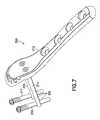
- FIG. 7is a perspective view of a third embodiment of a proximal humeral fixation system according to the invention.
- FIGS. 1 through 4a first embodiment of a proximal humeral fixation system 10 for fixation of a humeral fracture 11 ( FIG. 4 ) of the left arm is shown.
- the system 10includes a humeral plate 12 , and a plurality of rigid posts 14 , rigid cross pegs 16 , set screws 18 , and cortical screws 19 , all for coupling the plate 12 to the humerus 20 ( FIG. 4 ) and stabilizing the fracture.
- the system 10preferably also includes K-wires 22 and suture material 24 , as discussed below.
- the humeral plate 12has a shaft portion 30 and a head portion 34 .
- the head portion 34is angled slightly relatively to the shaft portion to properly seat on the humeral anatomy.
- the shaft portion 30includes screw holes 32 , one of which may be slotted or oblong (as indicated by dotted line 32 a in FIG. 1 ) to permit the plate 12 to be longitudinally moved relative to a screw placed therethrough.
- the shaft portionmay also include one or more K-wire holes 33 .
- the head portion 34is provided with post holes 36 . As indicated by the posts 14 in FIG. 1 , axes through the post holes 36 are preferably substantially in a common plane but preferably diverge from each other within the common plane.
- the planeis in 10° retroversion relative to a frontal and vertical plane.
- the post holes 36define a locking structure 38 , discussed in more detail below.
- tangential to each post holes 36 on diametrically opposite sides thereofare slots 40 for receiving an alignment jig (not shown) to aid in drilling respective holes for cross pegs 16 .
- each post 14is provided for each post hole 36 , and extends through the head portion 34 of the plate 12 generally perpendicular to the articular surface 42 of the humeral head 44 ( FIG. 4 ).
- each post 14includes a head portion 46 with slots 48 which lock in a particular rotational orientation relative to the locking structure 38 of the post hole 36 , similar to a bayonet lock.
- each post 14be locked relative to the plate 12 without a threaded coupling therebetween, because it is difficult to machine a threaded coupling in which (i) the components are both fixedly and rigidly coupled together, and (ii) in which the rotational orientation of the post can be predetermined with certainty upon locking.
- the lock between a post 14 and its respective post hole 36preferably occurs within less than one complete rotation of the post 14 relative to the post hole 36 , and more preferably within 90° rotation.
- the post 14also includes a plurality of transverse, preferably parallel holes 50 longitudinally displaced along the shaft 52 of the post 14 .
- the post 14further includes an axial bore 54 which extends from the head portion 46 at least to the furthest transverse hole 50 , and an internal thread (not shown) below a driver recess 56 and preferably below the slots 48 .
- the cross pegs 16each include a head 60 for receiving a driver, and a shaft portion 62 .
- the shaft portion 62is optionally threaded at 64 adjacent the head 60 for engagement with cancellous bone, but such is not required.
- the cross pegs 16can be extended through a transverse hole 50 in a post 14 in the anterior-posterior plane and locked in place with a set screw 18 .
- the set screw 18includes a head 66 with a driver recess 68 and external threads 70 , and a shaft 72 .
- a set screw of appropriate lengthis inserted through the axial bore 54 of the post 14 until the end 76 of the set screw 18 contacts the portion of the shaft 62 of the cross peg 16 extending through a transverse hole 50 of the post 14 .
- the set screw 18is threadably locked relative to the post 14 to exert pressure on the cross peg 16 and thereby retain the cross peg 16 .
- Set screws 18 of various lengthsmay be provided for locking cross pegs in any of the longitudinally displaced transverse holes.
- common length set screwsmay be cut down in size, if necessary, to the appropriate length prior to insertion through the bore 54 of a post 14 .
- the set screws 18may be scored along the shaft 72 to facilitate breaking or cutting the set screws to appropriate length.
- the cross pegsmay include transverse holes through which the set screws can be passed. In that manner common length set screws can be used, provided the cross pegs are rotationally aligned to receive the set screws through the transverse holes.
- the head portion 34 of the plate 12includes a lower proximal recess 80 and a plurality of suture holes 82 thereabout.
- the recess 80raises the proximal portion of the head portion 34 of the plate 12 off the surface of the bone (as shown in FIG. 4 ) to allow the surgeon to pass a needle (not shown) with suture material 24 through the suture holes 82 and between the plate 12 and the bone 20 .
- suture material 24can be used to secure tendons 84 of the rotator cuff to the plate 12 to place retaining force on smaller fragments of the fracture.
- the suture material 24is preferably metal braid or cable.
- the head portion 34includes a plurality of alignment holes 86 , 88 , and 90 which are sized to closely receive individual K-wires in a particular orientation.
- proximal alignment hole 86is located to define an axis which corresponds to the anterior-superior boundary of the posts 14
- distal alignment hole 88is located to define an axis which corresponds to the anterior-inferior boundary of the posts 14
- relatively central alignment hole 90is located to define an axis which corresponds to the posterior boundary of the posts 14 .
- the fractureis reduced and the humeral plate 12 is placed on the proximal humerus in an apparently appropriate location, with the head portion 34 generally opposite the articular surface 42 .
- the head portion 34is then tacked onto the humeral head 44 with K-wires 22 drilled through the alignment holes 86 , 88 , 90 , and the shaft portion 30 is preferably tacked to the distal fragment with one or more K-wires 22 , through K-wires holes 33 in the shaft portion, or with one or more screws 19 in the screw holes 32 .
- the fracture and location of the K-wires 22are examined, e.g., under fluoroscopy, to determine whether the fracture is reduced in an anatomically correct manner and if the K-wires 22 are properly aligned relative to the anatomy.
- the fluoroscopically viewed K-wires 22provide an indication as to whether the posts 14 will be properly oriented in relation to the fracture and the articular surface of the subchondral bone. If placement is not optimal, the K-wires 22 can be removed and the surgeon has an opportunity to relocate and/or reorient the K-wires 22 and drill again. Since each K-wire 22 is of relatively small diameter relative to the posts 14 , the bone is not significantly damaged by the drilling process and the surgeon is not committed to the initial drill location and/or orientation.
- shaft portion 30 fixationmay be delayed until after placement of the head portion 34 of the plate 12 is determined to be desirable (via visualization of the K-wires), and then preferably at least one cortical screw 19 is inserted through a screw hole 32 to stabilize the shaft portion 30 to the humerus 20 .
- Holesare then drilled through the post holes 36 of the head portion 34 of the plate 12 for the posts 14 .
- the holesare drilled across fracture 11 .
- the drill bit for drilling holes through the posts 14corresponds in diameter to the post holes 36 such that no alignment jig is necessarily required, although one may be used is desired.
- the holesare drilled through the relatively soft spongy bone of the humeral head 44 until the surgeon can ‘feel’ the harder cortex of the subchondral bone of the articular surface 42 . All posts holes may be drilled before proceeding.
- one post holemay be drilled, and for that post hole, a post can be inserted therein and coupled to the plate, an associated cross peg hole can be drilled, and a cross peg can be coupled to the post, as described in more detail below, prior to proceeding to drill the other post holes.
- the posts 14are then inserted through the post holes 36 , and rotated to lock the heads 46 of the posts 14 relative to the locking structure 38 of the head portion 34 of the plate 12 .
- the locking coupling of 46 and 38constrains the transverse holes 50 to be in a predetermined rotational orientation relative to the plate 12 .
- a jig(not shown) is then coupled to the internal threads of a post 14 and rotationally aligned relative to the tangential slots 40 of the post hole 36 to align a guide for drilling a hole in alignment with one of the transverse holes 50 of that post 14 .
- the jigmay be coupled directly the plate 12 .
- the jigis removed.
- a cross peg 16is then inserted through the drilled hole and extended through the transverse hole 50 of that post 14 such that the cross peg 16 extends parallel to the articular surface 42 of the humeral head 44 on the opposite side of the fracture 11 from the plate 12 .
- the particular transverse hole 50 in which a particular cross peg 16 is insertedcan be determined by the surgeon based upon the size of the humeral head 44 and the location of the fracture. More particularly, it is desirable for each cross peg 16 to extend just below the articular surface 42 . If the cross peg 16 is within the articular surface 42 it will cause interference with the joint. If the cross peg 16 is too far away from the articular surface 42 , there will be too much spongy bone between the hard articular surface 42 and the cross peg 16 which could cause the fractured humeral head 44 to collapse.
- the cross pegs 16are subject to little resistance through the drilled holes and the surgeon has tactile sensation as to when the cross pegs 16 have been extended through the appropriate transverse holes 50 and when the ends of the cross pegs have reached hard cortical bone. It is undesirable to force the cross pegs through the cortical bone such that the ends of the cross pegs 16 are exposed.
- the cross peg 16is properly positioned, it is desirable to lock it in position.
- the set screw 18is inserted through the axial bore 54 of the post 14 and threadably coupled to the post 14 such that the end of the set screw 18 seats against the cross peg 16 locking the cross peg in place. The process is repeated for the other posts 14 and cross pegs 16 .
- the K-wires 22are removed.
- the sutures 24are added, and the remaining cortical screws 19 , if not already inserted, are inserted to further stabilize the fracture.
- the posts 14are oriented perpendicular to the articular surface 42 but do not extend far enough to break through the articular surface.
- the plate 12 and cross pegs 16sandwich the fracture 11 to provide a stabilizing framework.
- the cross pegs 16 extending through the transverse holes 50 in the posts 14are oriented parallel to the articular surface 42 and provide a structure which locks the plate relative to the bone. Furthermore, such placement and orientation of the cross pegs 16 will not result in any damage to, irritation to, or interference with the articular surface of the shoulder joint.
- FIG. 5an alternative embodiment of a cross peg 116 for the fracture fixation system is shown.
- the cross peg 116includes threads 190 along a central portion of its shaft which are preferably self-tapping and spaced appropriately to engage the wall 51 surrounding the holes 50 of the post 14 .
- this threaded engagementmay limit the surgeon's tactile sensation of when the far cortex is reached by the cross peg.
- the cross peg 116may be provided with a shoulder 192 that limits its introduction, i.e. such that the shoulder 192 can not extend through the transverse hole 50 .
- the cross peg 116may include cutting flutes 194 which permit drill-less introduction.
- transverse holesmay be provide with machine threads, and the cross pegs may be likewise threaded with machine threads such that the cross peg and post can threadably engage together without the cross peg tapping into the post.
- any of the above described cross pegsmay be headless.
- the cross pegis adapted to be seated beneath the surface of the bone.
- such a crossis suited to extend through the articular surface without interference with the shoulder joint if extension of a cross peg through the articular surface is necessary or desirable for stabilization of a particular fracture with the system of the invention.
- a single post 214may be inserted through any of the post holes 236 in plate 212 , although only a single post hole is required in this embodiment.
- the post 214includes holes 250 , 252 which are oriented transverse to each other, preferably at 90°, and preferably perpendicular to the longitudinal axis of the post 214 .
- Cross pegs 216 , 217are then inserted through holes 250 , 252 and preferably locked relative to the post.
- Cross peg 216extends parallel to the anterior-posterior plane of the articular surface, and cross peg 217 extends parallel to the relatively transverse plane.
- Cross pegs 216 , 217are also shown in a headless design, described above, which can be seated beneath the surface of the bone and provide no interference with the articular surface.
- FIG. 7another embodiment of humeral fracture fixation system 310 according to the invention is shown.
- two posts 314 , 315are displaced in an anterior-posterior plane.
- the postsare preferably angled relative to each other in the same plane by, e.g., 20° to 90°.
- the posts 314 , 315may be vertically offset in the proximal-distal plane.
- Each of the posts 314 , 315has at least one transverse hole 350 , with an axis therethrough preferably oriented substantially transverse to the anterior-posterior plane when the system 310 is implanted at the shoulder, and may have a plurality of such holes 350 longitudinally displaced along the post.
- a cross peg 316 , 317is inserted through a selected one of the holes 350 in each post 314 , 315 .
- posts and cortical screwshave been disclosed in relation to particular embodiments, it will be understood that only one post is required, and fewer or more cortical screw holes and/or screws than shown can be used.
- cortical screwsare disclosed for coupling the shaft portion to the bone, other fasteners can likewise be used.
- postsand ‘pegs’ have been used to described particular elements of the invention, it is understood that such terms are used as a matter of convenience, and are not intended to confer particular structure when used in the claims. Thus, what is referred to as a ‘post’ is intended to broadly read on any rigid shaft-like fastener mechanically coupled to, but not integral with the plate.
- pegis intended to broadly read on any shaft-like element which extends in transverse relation one of the posts and is (i) coupled to such post and/or (ii) extends through a transverse hole formed within the post.
- the pegmay be a screw, a non-threaded rod, a K-wire, etc.
- left-hand humeral platesare shown, it is recognized that right-hand humeral plates are generally mirror-images of the illustrated left-hand plates.
Landscapes
- Health & Medical Sciences (AREA)
- Orthopedic Medicine & Surgery (AREA)
- Surgery (AREA)
- Life Sciences & Earth Sciences (AREA)
- Heart & Thoracic Surgery (AREA)
- Nuclear Medicine, Radiotherapy & Molecular Imaging (AREA)
- Engineering & Computer Science (AREA)
- Biomedical Technology (AREA)
- Neurology (AREA)
- Medical Informatics (AREA)
- Molecular Biology (AREA)
- Animal Behavior & Ethology (AREA)
- General Health & Medical Sciences (AREA)
- Public Health (AREA)
- Veterinary Medicine (AREA)
- Surgical Instruments (AREA)
- Prostheses (AREA)
Abstract
Description
Claims (7)
Priority Applications (1)
| Application Number | Priority Date | Filing Date | Title |
|---|---|---|---|
| US11/040,734US7001388B2 (en) | 2004-01-23 | 2005-01-21 | System for stabilization of fractures of convex articular bone surfaces including subchondral support structure |
Applications Claiming Priority (3)
| Application Number | Priority Date | Filing Date | Title |
|---|---|---|---|
| US53858904P | 2004-01-23 | 2004-01-23 | |
| US54612704P | 2004-02-20 | 2004-02-20 | |
| US11/040,734US7001388B2 (en) | 2004-01-23 | 2005-01-21 | System for stabilization of fractures of convex articular bone surfaces including subchondral support structure |
Publications (2)
| Publication Number | Publication Date |
|---|---|
| US20050165395A1 US20050165395A1 (en) | 2005-07-28 |
| US7001388B2true US7001388B2 (en) | 2006-02-21 |
Family
ID=34830463
Family Applications (1)
| Application Number | Title | Priority Date | Filing Date |
|---|---|---|---|
| US11/040,734Expired - LifetimeUS7001388B2 (en) | 2004-01-23 | 2005-01-21 | System for stabilization of fractures of convex articular bone surfaces including subchondral support structure |
Country Status (5)
| Country | Link |
|---|---|
| US (1) | US7001388B2 (en) |
| EP (1) | EP1713410B1 (en) |
| AT (1) | ATE489046T1 (en) |
| DE (1) | DE602005024920D1 (en) |
| WO (1) | WO2005072285A2 (en) |
Cited By (61)
| Publication number | Priority date | Publication date | Assignee | Title |
|---|---|---|---|---|
| US20040111090A1 (en)* | 2002-10-03 | 2004-06-10 | The University Of North Carolina At Chapel Hill | Modification of percutaneous intrafocal plate system |
| US20060264951A1 (en)* | 2005-05-18 | 2006-11-23 | Nelson Charles L | Minimally Invasive Actuable Bone Fixation Devices Having a Retractable Interdigitation Process |
| US20070270853A1 (en)* | 2006-04-11 | 2007-11-22 | Ebi, L.P. | Contoured bone plate |
| US20080132896A1 (en)* | 2006-11-22 | 2008-06-05 | Sonoma Orthopedic Products, Inc. | Curved orthopedic tool |
| US20080140078A1 (en)* | 2006-11-22 | 2008-06-12 | Sonoma Orthopedic Products, Inc. | Surgical tools for use in deploying bone repair devices |
| US20080149115A1 (en)* | 2006-11-22 | 2008-06-26 | Sonoma Orthopedic Products, Inc. | Surgical station for orthopedic reconstruction surgery |
| US20080161805A1 (en)* | 2006-11-22 | 2008-07-03 | Sonoma Orthopedic Products, Inc. | Fracture fixation device, tools and methods |
| US20080188897A1 (en)* | 2006-10-02 | 2008-08-07 | The Cleveland Clinic Foundation | Fastener assembly |
| US20090088805A1 (en)* | 2007-09-27 | 2009-04-02 | Depuy Products, Inc. | Plate holder and bone plate arrangement |
| US20090228010A1 (en)* | 2008-03-10 | 2009-09-10 | Eduardo Gonzalez-Hernandez | Bone fixation system |
| US20100211174A1 (en)* | 2009-02-19 | 2010-08-19 | Tyco Healthcare Group Lp | Method For Repairing A Rotator Cuff |
| US20100274245A1 (en)* | 2003-11-21 | 2010-10-28 | Eduardo Gonzalez-Hernandez | Fracture fixation system |
| US20110152943A1 (en)* | 2009-12-22 | 2011-06-23 | Eduardo Gonzalez-Hernandez | Bone plate and tool assembly and method for use thereof |
| US20110224736A1 (en)* | 2010-03-09 | 2011-09-15 | Humphrey C Scott | Proximal humerus fracture repair plate and system |
| US20120083848A1 (en)* | 2010-10-05 | 2012-04-05 | Eduardo Gonzalez-Hernandez | System and method for facilitating repair and reattachment of comminuted bone portions |
| US20120226322A1 (en)* | 2011-03-04 | 2012-09-06 | Eduardo Gonzalez-Hernandez | Extra-medullary cortical buttress fixation device and method of use associated therewith |
| US8267973B2 (en) | 2008-02-27 | 2012-09-18 | Shoulder Options, Inc. | Fixable suture anchor plate and method for tendon-to-bone repair |
| US8287541B2 (en) | 2005-05-18 | 2012-10-16 | Sonoma Orthopedic Products, Inc. | Fracture fixation device, tools and methods |
| US20130096629A1 (en)* | 2010-07-09 | 2013-04-18 | Medartis Ag | Osteosynthesis System |
| US8449583B2 (en) | 2006-10-02 | 2013-05-28 | The Cleveland Clinic Foundation | Fastener assembly |
| US8469999B2 (en) | 2008-04-17 | 2013-06-25 | Eduardo Gonzalez-Hernandez | Soft tissue attachment system and clip |
| US8591554B2 (en) | 2010-05-07 | 2013-11-26 | Osteomed Llc | System for treating bone fractures |
| US8870963B2 (en) | 2010-10-27 | 2014-10-28 | Toby Orthopaedics, Inc. | System and method for fracture replacement of comminuted bone fractures or portions thereof adjacent bone joints |
| US8961516B2 (en) | 2005-05-18 | 2015-02-24 | Sonoma Orthopedic Products, Inc. | Straight intramedullary fracture fixation devices and methods |
| US20150134010A1 (en)* | 2013-09-19 | 2015-05-14 | Dan Zlotolow | Variable angle blade plate system and method |
| US9060820B2 (en) | 2005-05-18 | 2015-06-23 | Sonoma Orthopedic Products, Inc. | Segmented intramedullary fracture fixation devices and methods |
| US9155574B2 (en) | 2006-05-17 | 2015-10-13 | Sonoma Orthopedic Products, Inc. | Bone fixation device, tools and methods |
| US9254154B2 (en) | 2011-03-03 | 2016-02-09 | Toby Orthopaedic, Inc. | Anterior lesser tuberosity fixed angle fixation device and method of use associated therewith |
| US9271772B2 (en) | 2011-10-27 | 2016-03-01 | Toby Orthopaedics, Inc. | System and method for fracture replacement of comminuted bone fractures or portions thereof adjacent bone joints |
| US9283008B2 (en) | 2012-12-17 | 2016-03-15 | Toby Orthopaedics, Inc. | Bone plate for plate osteosynthesis and method for use thereof |
| US9308034B2 (en) | 2003-05-30 | 2016-04-12 | DePuy Synthes Products, Inc. | Bone plate |
| US9314283B2 (en) | 2011-11-18 | 2016-04-19 | DePuy Synthes Products, Inc. | Femoral neck fracture implant |
| US9333014B2 (en) | 2013-03-15 | 2016-05-10 | Eduardo Gonzalez-Hernandez | Bone fixation and reduction apparatus and method for fixation and reduction of a distal bone fracture and malunion |
| US9402667B2 (en) | 2011-11-09 | 2016-08-02 | Eduardo Gonzalez-Hernandez | Apparatus and method for use of the apparatus for fracture fixation of the distal humerus |
| US20160270830A1 (en)* | 2015-03-22 | 2016-09-22 | Rahul Vaidya | Method and Apparatus for Minimally Invasive Subcutaneous Treatment of Humerus Fractures |
| US20160324555A1 (en)* | 2015-05-06 | 2016-11-10 | Treace Medical Concepts, Inc. | Intra-osseous plate system and method |
| US9510880B2 (en) | 2013-08-13 | 2016-12-06 | Zimmer, Inc. | Polyaxial locking mechanism |
| US9730797B2 (en) | 2011-10-27 | 2017-08-15 | Toby Orthopaedics, Inc. | Bone joint replacement and repair assembly and method of repairing and replacing a bone joint |
| US9770278B2 (en) | 2014-01-17 | 2017-09-26 | Arthrex, Inc. | Dual tip guide wire |
| US9788871B2 (en) | 2002-08-10 | 2017-10-17 | Howmedica Osteonics Corp. | Method and apparatus for repairing the mid-foot region via an intramedullary nail |
| US9814499B2 (en) | 2014-09-30 | 2017-11-14 | Arthrex, Inc. | Intramedullary fracture fixation devices and methods |
| US20180078290A1 (en)* | 2016-09-22 | 2018-03-22 | Globus Medical, Inc. | Systems and methods for intramedullary nail implantation |
| US10213237B2 (en) | 2014-10-03 | 2019-02-26 | Stryker European Holdings I, Llc | Periprosthetic extension plate |
| US10238438B2 (en) | 2015-04-22 | 2019-03-26 | Flower Orthopedics Corporation | Proximal humeral fracture plate |
| US10251685B2 (en) | 2016-03-17 | 2019-04-09 | Stryker European Holdings I, Llc | Floating locking insert |
| US10335211B2 (en) | 2004-01-26 | 2019-07-02 | DePuy Synthes Products, Inc. | Highly-versatile variable-angle bone plate system |
| US10335214B2 (en) | 2009-04-24 | 2019-07-02 | DePuy Synthes Products, Inc. | Multiplexed screws |
| US10342586B2 (en) | 2003-08-26 | 2019-07-09 | DePuy Synthes Products, Inc. | Bone plate |
| USD871578S1 (en) | 2015-04-22 | 2019-12-31 | Anup A. Shah | Proximal humeral fracture plate |
| US10624686B2 (en) | 2016-09-08 | 2020-04-21 | DePuy Synthes Products, Inc. | Variable angel bone plate |
| US10687860B2 (en) | 2012-04-24 | 2020-06-23 | Retrospine Pty Ltd | Segmental correction of lumbar lordosis |
| US10772665B2 (en) | 2018-03-29 | 2020-09-15 | DePuy Synthes Products, Inc. | Locking structures for affixing bone anchors to a bone plate, and related systems and methods |
| US10792081B2 (en) | 2014-08-28 | 2020-10-06 | Nextremity Solutions, Inc. | Bone fixation devices and methods |
| US10820930B2 (en) | 2016-09-08 | 2020-11-03 | DePuy Synthes Products, Inc. | Variable angle bone plate |
| US10905476B2 (en) | 2016-09-08 | 2021-02-02 | DePuy Synthes Products, Inc. | Variable angle bone plate |
| US10925651B2 (en) | 2018-12-21 | 2021-02-23 | DePuy Synthes Products, Inc. | Implant having locking holes with collection cavity for shavings |
| US11013541B2 (en) | 2018-04-30 | 2021-05-25 | DePuy Synthes Products, Inc. | Threaded locking structures for affixing bone anchors to a bone plate, and related systems and methods |
| US11026727B2 (en) | 2018-03-20 | 2021-06-08 | DePuy Synthes Products, Inc. | Bone plate with form-fitting variable-angle locking hole |
| US11213334B2 (en) | 2015-10-07 | 2022-01-04 | Stabiliz Orthopaedics, LLC | Bone fracture fixation device with transverse set screw and aiming guide |
| US11259851B2 (en) | 2003-08-26 | 2022-03-01 | DePuy Synthes Products, Inc. | Bone plate |
| US11291484B2 (en) | 2004-01-26 | 2022-04-05 | DePuy Synthes Products, Inc. | Highly-versatile variable-angle bone plate system |
Families Citing this family (43)
| Publication number | Priority date | Publication date | Assignee | Title |
|---|---|---|---|---|
| US7326212B2 (en) | 2002-11-19 | 2008-02-05 | Acumed Llc | Bone plates with reference marks |
| US7717945B2 (en) | 2002-07-22 | 2010-05-18 | Acumed Llc | Orthopedic systems |
| US20050240187A1 (en) | 2004-04-22 | 2005-10-27 | Huebner Randall J | Expanded fixation of bones |
| US7537604B2 (en)* | 2002-11-19 | 2009-05-26 | Acumed Llc | Bone plates with slots |
| CN1309352C (en)* | 2002-07-22 | 2007-04-11 | 精密医疗责任有限公司 | Bone fusion system |
| AU2003294342A1 (en) | 2002-11-19 | 2004-06-15 | Acumed Llc | Guide system for bone-repair devices |
| AU2003294414B2 (en)* | 2002-11-19 | 2009-03-12 | Acumed Llc | Deformable bone plates |
| WO2004112587A2 (en) | 2003-06-20 | 2004-12-29 | Acumed Llc | Bone plates with intraoperatively tapped apertures |
| US7635365B2 (en) | 2003-08-28 | 2009-12-22 | Ellis Thomas J | Bone plates |
| US20050085818A1 (en)* | 2003-10-17 | 2005-04-21 | Huebner Randall J. | Systems for distal radius fixation |
| AU2005206175A1 (en)* | 2004-01-16 | 2005-08-04 | Expanding Orthopedics, Inc. | Bone fracture treatment devices |
| DE102004009429A1 (en)* | 2004-02-24 | 2005-09-22 | Biedermann Motech Gmbh | Bone anchoring element |
| WO2005102193A2 (en) | 2004-04-19 | 2005-11-03 | Acumed, Llc | Placement of fasteners into bone |
| US8568413B2 (en)* | 2008-12-18 | 2013-10-29 | Sonoma Orthopedic Products, Inc. | Bone fixation device, tools and methods |
| KR101145415B1 (en)* | 2005-07-08 | 2012-05-15 | 비이더만 모테크 게엠베하 & 코. 카게 | Bone Anchoring Element |
| ES2318391T3 (en)* | 2005-08-05 | 2009-05-01 | Biedermann Motech Gmbh | OSEO ANCHORAGE ELEMENT. |
| ES2313472T3 (en)* | 2006-02-23 | 2009-03-01 | Biedermann Motech Gmbh | OSEO ANCHORAGE DEVICE. |
| US20090018542A1 (en)* | 2007-07-11 | 2009-01-15 | Sonoma Orthopedic Products,Inc. | Fracture fixation devices, systems and methods incorporating a membrane |
| US8545539B2 (en)* | 2008-05-12 | 2013-10-01 | Edwin E. Spencer | Proximal humeral fracture reduction and fixation device |
| US20130244193A1 (en)* | 2008-07-10 | 2013-09-19 | Nei-Chang Yu | System and Method for Orthodontic System |
| US12285197B2 (en) | 2008-10-10 | 2025-04-29 | Acumed Llc | Bone fixation system with opposed mounting portions |
| US9237910B2 (en) | 2012-01-26 | 2016-01-19 | Acute Innovations Llc | Clip for rib stabilization |
| WO2011044917A1 (en)* | 2009-10-13 | 2011-04-21 | Zimmer Gmbh | An orthopedic nail and an orthopedic nail system |
| US8568417B2 (en) | 2009-12-18 | 2013-10-29 | Charles River Engineering Solutions And Technologies, Llc | Articulating tool and methods of using |
| FR2956971B1 (en) | 2010-03-08 | 2012-03-02 | Memometal Technologies | PLATE OSTEOSYNTHESIS SYSTEM |
| US20110218580A1 (en)* | 2010-03-08 | 2011-09-08 | Stryker Trauma Sa | Bone fixation system with curved profile threads |
| FR2956972B1 (en) | 2010-03-08 | 2012-12-28 | Memometal Technologies | ARTICULATED OSTEOSYNTHESIS PLATE |
| US8808340B1 (en) | 2010-04-30 | 2014-08-19 | SonicSurg Innovations, LLC | Device for repairing a bone fracture |
| US8579945B2 (en) | 2010-08-13 | 2013-11-12 | DePuy Synthes Products, LLC | Bone stabilization device |
| WO2013049849A2 (en) | 2011-09-30 | 2013-04-04 | Acute Innovations, Llc, An Oregon Limited Liability Company | Bone fixation system with opposed mounting portions |
| WO2014110421A1 (en)* | 2013-01-11 | 2014-07-17 | The Uab Research Foundation | Apparatus for the fixation of proximal humerus fractures |
| EP3164093B1 (en) | 2014-07-03 | 2024-02-14 | Acumed LLC | Bone plate with movable joint |
| EP3273889B1 (en)* | 2015-03-25 | 2020-12-02 | Pier Giovanni Menci | Intramedullary nail for the treatment of fractures of long bones |
| CN106264697A (en)* | 2016-08-31 | 2017-01-04 | 常州华森医疗器械有限公司 | Greater tuberosity anatomical form steel plate |
| WO2018067538A1 (en)* | 2016-10-04 | 2018-04-12 | Acumed Llc | Fixation system and method for hoffa fractures |
| CN106725796B (en)* | 2016-12-16 | 2019-02-01 | 常州华森医疗器械有限公司 | Proximal humerus anatomical plate |
| US11033303B2 (en)* | 2017-03-13 | 2021-06-15 | Extremity Medical, Llc | Calcaneal cross medullary plate |
| WO2018187770A1 (en)* | 2017-04-06 | 2018-10-11 | Extremity Medical, Llc | Orthopedic plate with modular peg and compression screw |
| CN110537967B (en)* | 2019-09-20 | 2023-11-10 | 山东中医药大学附属医院 | An anatomical auxiliary plate for the posterior proximal humerus |
| BE1028532B1 (en) | 2020-08-05 | 2022-03-07 | Bv Dr Guy Putzeys | PROXIMAL HUMERAL FIXATION SYSTEM |
| CN112617996B (en)* | 2020-12-29 | 2021-12-28 | 中国科学院大学宁波华美医院 | A Lisfranc Injury Inter-articular Locking Plate |
| EP4460249A1 (en) | 2022-01-04 | 2024-11-13 | Extremity Medical, LLC | Orthopedic plate with locking compression slot |
| WO2024047400A1 (en)* | 2022-09-01 | 2024-03-07 | Rlfa Consultants Ltd | Screw capture system for calcaneal fracture |
Citations (27)
| Publication number | Priority date | Publication date | Assignee | Title |
|---|---|---|---|---|
| US2500370A (en) | 1947-06-30 | 1950-03-14 | Mckibbin Genevieve | Repair of femur fracture |
| US3489143A (en) | 1967-12-15 | 1970-01-13 | William X Halloran | Convertible hip pin |
| FR2606268A1 (en) | 1986-11-07 | 1988-05-13 | Landos Applic Orthopediques Fs | Device for osteosynthesis of the neck of the femur |
| US4794919A (en) | 1986-01-31 | 1989-01-03 | Nilsson John S | Fixating device |
| US4858602A (en) | 1985-12-06 | 1989-08-22 | Howmedica GmbH Werk Schonkirchen | Bone nail for the treatment of upper arm fractures |
| DE9200328U1 (en) | 1992-01-14 | 1992-02-27 | Howmedica GmbH, 2314 Schönkirchen | Locking nail for the treatment of fractures of the proximal femur |
| US5180383A (en) | 1991-10-09 | 1993-01-19 | Haydon Frank A | Method and device for attaching artificial joint implants to the ends of bones |
| US5190544A (en) | 1986-06-23 | 1993-03-02 | Pfizer Hospital Products Group, Inc. | Modular femoral fixation system |
| US5458654A (en) | 1993-07-14 | 1995-10-17 | Ao-Forschungsinstitut Davos | Screw-fixed femoral component for hip joint prosthesis |
| US5472444A (en) | 1994-05-13 | 1995-12-05 | Acumed, Inc. | Humeral nail for fixation of proximal humeral fractures |
| US5578035A (en) | 1995-05-16 | 1996-11-26 | Lin; Chih-I | Expandable bone marrow cavity fixation device |
| US5676667A (en) | 1995-12-08 | 1997-10-14 | Hausman; Michael | Bone fixation apparatus and method |
| US5709686A (en) | 1995-03-27 | 1998-01-20 | Synthes (U.S.A.) | Bone plate |
| US5749872A (en) | 1995-09-08 | 1998-05-12 | Ace Medical Company | Keyed/keyless barrel for bone plates |
| US5776194A (en) | 1996-04-25 | 1998-07-07 | Nuvana Medical Innovations, Llc | Intermedullary rod apparatus and methods of repairing proximal humerus fractures |
| US5931839A (en) | 1995-01-27 | 1999-08-03 | Medoff; Robert J. | Pin plate for fixation of bone fractures |
| US6096040A (en) | 1996-06-14 | 2000-08-01 | Depuy Ace Medical Company | Upper extremity bone plates |
| USD443060S1 (en) | 2000-06-01 | 2001-05-29 | Bristol-Myers Squibb Company | Bone plate |
| US6270499B1 (en) | 1997-10-20 | 2001-08-07 | Synthes (U.S.A.) | Bone fixation device |
| US6358250B1 (en) | 2000-02-01 | 2002-03-19 | Hand Innovations, Inc. | Volar fixation system |
| US6379359B1 (en) | 2000-05-05 | 2002-04-30 | University Of North Carolina At Chapel Hill | Percutaneous intrafocal plate system |
| US6409768B1 (en) | 2000-03-16 | 2002-06-25 | Slobodan Tepic | Screw anchored joint prosthesis |
| US6440135B2 (en) | 2000-02-01 | 2002-08-27 | Hand Innovations, Inc. | Volar fixation system with articulating stabilization pegs |
| US6468278B1 (en) | 1997-11-14 | 2002-10-22 | Medos Medizintechnik Gmbh | Implant for the stabilization of a fracture |
| US6623486B1 (en) | 1999-09-13 | 2003-09-23 | Synthes (U.S.A.) | bone plating system |
| US20050010226A1 (en) | 2003-05-30 | 2005-01-13 | Grady Mark P. | Bone plate |
| US6866665B2 (en) | 2003-03-27 | 2005-03-15 | Hand Innovations, Llc | Bone fracture fixation system with subchondral and articular surface support |
Family Cites Families (9)
| Publication number | Priority date | Publication date | Assignee | Title |
|---|---|---|---|---|
| US4733654A (en) | 1986-05-29 | 1988-03-29 | Marino James F | Intramedullar nailing assembly |
| DE8907443U1 (en) | 1989-06-19 | 1989-09-14 | Aesculap AG, 7200 Tuttlingen | Intramedullary splint for a long bone |
| JPH04138152A (en)* | 1990-09-29 | 1992-05-12 | Ikufumi Yamada | Internal fixing tool for collum humeri fracture |
| US5674222A (en)* | 1994-06-01 | 1997-10-07 | Synthes (U.S.A.) | Forked plate |
| US5976139A (en) | 1996-07-17 | 1999-11-02 | Bramlet; Dale G. | Surgical fastener assembly |
| DE19857279A1 (en)* | 1998-12-11 | 2000-06-15 | Onur Tarhan | Bone screw |
| DE29907161U1 (en)* | 1999-04-22 | 2000-08-24 | Wischhöfer, Edlef, Prof. Dr. Dr.med., 85092 Kösching | Blocking plate for osteosynthesis on the humerus |
| JP4138152B2 (en) | 1999-05-28 | 2008-08-20 | ヤンマー株式会社 | Tractor air conditioner structure |
| DE10348932B4 (en) | 2003-10-18 | 2006-01-19 | Intercus Gmbh | System for the minimally invasive treatment of a proximal humeral or femoral fracture |
- 2005
- 2005-01-21USUS11/040,734patent/US7001388B2/ennot_activeExpired - Lifetime
- 2005-01-21WOPCT/US2005/002075patent/WO2005072285A2/enactiveApplication Filing
- 2005-01-21DEDE602005024920Tpatent/DE602005024920D1/ennot_activeExpired - Lifetime
- 2005-01-21EPEP05706033Apatent/EP1713410B1/ennot_activeExpired - Lifetime
- 2005-01-21ATAT05706033Tpatent/ATE489046T1/ennot_activeIP Right Cessation
Patent Citations (28)
| Publication number | Priority date | Publication date | Assignee | Title |
|---|---|---|---|---|
| US2500370A (en) | 1947-06-30 | 1950-03-14 | Mckibbin Genevieve | Repair of femur fracture |
| US3489143A (en) | 1967-12-15 | 1970-01-13 | William X Halloran | Convertible hip pin |
| US4858602A (en) | 1985-12-06 | 1989-08-22 | Howmedica GmbH Werk Schonkirchen | Bone nail for the treatment of upper arm fractures |
| US4794919A (en) | 1986-01-31 | 1989-01-03 | Nilsson John S | Fixating device |
| US5190544A (en) | 1986-06-23 | 1993-03-02 | Pfizer Hospital Products Group, Inc. | Modular femoral fixation system |
| FR2606268A1 (en) | 1986-11-07 | 1988-05-13 | Landos Applic Orthopediques Fs | Device for osteosynthesis of the neck of the femur |
| US5180383A (en) | 1991-10-09 | 1993-01-19 | Haydon Frank A | Method and device for attaching artificial joint implants to the ends of bones |
| DE9200328U1 (en) | 1992-01-14 | 1992-02-27 | Howmedica GmbH, 2314 Schönkirchen | Locking nail for the treatment of fractures of the proximal femur |
| US5458654A (en) | 1993-07-14 | 1995-10-17 | Ao-Forschungsinstitut Davos | Screw-fixed femoral component for hip joint prosthesis |
| US5472444A (en) | 1994-05-13 | 1995-12-05 | Acumed, Inc. | Humeral nail for fixation of proximal humeral fractures |
| US5931839A (en) | 1995-01-27 | 1999-08-03 | Medoff; Robert J. | Pin plate for fixation of bone fractures |
| US5709686A (en) | 1995-03-27 | 1998-01-20 | Synthes (U.S.A.) | Bone plate |
| US5578035A (en) | 1995-05-16 | 1996-11-26 | Lin; Chih-I | Expandable bone marrow cavity fixation device |
| US5749872A (en) | 1995-09-08 | 1998-05-12 | Ace Medical Company | Keyed/keyless barrel for bone plates |
| US5676667A (en) | 1995-12-08 | 1997-10-14 | Hausman; Michael | Bone fixation apparatus and method |
| US5776194A (en) | 1996-04-25 | 1998-07-07 | Nuvana Medical Innovations, Llc | Intermedullary rod apparatus and methods of repairing proximal humerus fractures |
| US6096040A (en) | 1996-06-14 | 2000-08-01 | Depuy Ace Medical Company | Upper extremity bone plates |
| US6270499B1 (en) | 1997-10-20 | 2001-08-07 | Synthes (U.S.A.) | Bone fixation device |
| US6468278B1 (en) | 1997-11-14 | 2002-10-22 | Medos Medizintechnik Gmbh | Implant for the stabilization of a fracture |
| US6623486B1 (en) | 1999-09-13 | 2003-09-23 | Synthes (U.S.A.) | bone plating system |
| US6358250B1 (en) | 2000-02-01 | 2002-03-19 | Hand Innovations, Inc. | Volar fixation system |
| US6364882B1 (en) | 2000-02-01 | 2002-04-02 | Hand Innovations, Inc. | Volar fixation system |
| US6440135B2 (en) | 2000-02-01 | 2002-08-27 | Hand Innovations, Inc. | Volar fixation system with articulating stabilization pegs |
| US6409768B1 (en) | 2000-03-16 | 2002-06-25 | Slobodan Tepic | Screw anchored joint prosthesis |
| US6379359B1 (en) | 2000-05-05 | 2002-04-30 | University Of North Carolina At Chapel Hill | Percutaneous intrafocal plate system |
| USD443060S1 (en) | 2000-06-01 | 2001-05-29 | Bristol-Myers Squibb Company | Bone plate |
| US6866665B2 (en) | 2003-03-27 | 2005-03-15 | Hand Innovations, Llc | Bone fracture fixation system with subchondral and articular surface support |
| US20050010226A1 (en) | 2003-05-30 | 2005-01-13 | Grady Mark P. | Bone plate |
Non-Patent Citations (4)
| Title |
|---|
| Locking Compression Plate (LCP) System (brochure). SYNTHES. West Chester, PA: 2003. (6 pages). |
| The Mayo Clinic Congruent Elbow Plates (catalog). ACUMED. Hillsboro, OR: 2003. (20 pages). |
| Two non-published pages of sketches made by Eduardo Gonzalez-Hernandez (intialed 'egh') in Miami, FL on Nov. 12, 2003, provided to inventor on that date. |
| Zimmer Periarticular Plating System-Low-Profile Fixation (catalog). Zimmer, Inc., 2003. (8 pages). |
Cited By (131)
| Publication number | Priority date | Publication date | Assignee | Title |
|---|---|---|---|---|
| US9788871B2 (en) | 2002-08-10 | 2017-10-17 | Howmedica Osteonics Corp. | Method and apparatus for repairing the mid-foot region via an intramedullary nail |
| US10925650B2 (en) | 2002-08-10 | 2021-02-23 | Howmedica Osteonics Corp. | Method and apparatus for repairing the mid-foot region via an intramedullary nail |
| US10238437B2 (en) | 2002-08-10 | 2019-03-26 | Howmedica Osteonics Corp. | Method and apparatus for repairing the mid-foot region via an intramedullary nail |
| US11666363B2 (en) | 2002-08-10 | 2023-06-06 | Howmedica Osteonics Corp. | Method and apparatus for repairing the mid-foot region via an intramedullary nail |
| US9867642B2 (en) | 2002-08-10 | 2018-01-16 | Howmedica Osteonics Corp. | Method and apparatus for repairing the mid-foot region via an intramedullary nail |
| US20040111090A1 (en)* | 2002-10-03 | 2004-06-10 | The University Of North Carolina At Chapel Hill | Modification of percutaneous intrafocal plate system |
| US10653466B2 (en) | 2003-05-30 | 2020-05-19 | DePuy Synthes Products, Inc. | Bone plate |
| US11419647B2 (en) | 2003-05-30 | 2022-08-23 | DePuy Synthes Products, Inc. | Bone plate |
| US10231768B2 (en) | 2003-05-30 | 2019-03-19 | DePuy Synthes Products, Inc. | Methods for implanting bone plates |
| US9931148B2 (en) | 2003-05-30 | 2018-04-03 | DePuy Synthes Products, Inc. | Bone plate |
| US9308034B2 (en) | 2003-05-30 | 2016-04-12 | DePuy Synthes Products, Inc. | Bone plate |
| US10342586B2 (en) | 2003-08-26 | 2019-07-09 | DePuy Synthes Products, Inc. | Bone plate |
| US11259851B2 (en) | 2003-08-26 | 2022-03-01 | DePuy Synthes Products, Inc. | Bone plate |
| US20100274245A1 (en)* | 2003-11-21 | 2010-10-28 | Eduardo Gonzalez-Hernandez | Fracture fixation system |
| US8182485B1 (en)* | 2003-11-21 | 2012-05-22 | Toby Orthopaedics, Llc | Fracture fixation system |
| US8574234B2 (en) | 2003-11-21 | 2013-11-05 | Toby Orthopaedics, Inc. | Fracture fixation system |
| US8361075B2 (en) | 2003-11-21 | 2013-01-29 | Toby Orthopaedics, Inc. | Method for repairing fractured bone |
| US11291484B2 (en) | 2004-01-26 | 2022-04-05 | DePuy Synthes Products, Inc. | Highly-versatile variable-angle bone plate system |
| US10335211B2 (en) | 2004-01-26 | 2019-07-02 | DePuy Synthes Products, Inc. | Highly-versatile variable-angle bone plate system |
| US7942875B2 (en) | 2005-05-18 | 2011-05-17 | Sonoma Orthopedic Products, Inc. | Methods of using minimally invasive actuable bone fixation devices |
| US7914533B2 (en) | 2005-05-18 | 2011-03-29 | Sonoma Orthopedic Products, Inc. | Minimally invasive actuable bone fixation devices |
| US8961516B2 (en) | 2005-05-18 | 2015-02-24 | Sonoma Orthopedic Products, Inc. | Straight intramedullary fracture fixation devices and methods |
| US7846162B2 (en) | 2005-05-18 | 2010-12-07 | Sonoma Orthopedic Products, Inc. | Minimally invasive actuable bone fixation devices |
| US20060264951A1 (en)* | 2005-05-18 | 2006-11-23 | Nelson Charles L | Minimally Invasive Actuable Bone Fixation Devices Having a Retractable Interdigitation Process |
| US9060820B2 (en) | 2005-05-18 | 2015-06-23 | Sonoma Orthopedic Products, Inc. | Segmented intramedullary fracture fixation devices and methods |
| US20070233105A1 (en)* | 2005-05-18 | 2007-10-04 | Nelson Charles L | Minimally invasive actuable bone fixation devices |
| US20060264952A1 (en)* | 2005-05-18 | 2006-11-23 | Nelson Charles L | Methods of Using Minimally Invasive Actuable Bone Fixation Devices |
| US20060264950A1 (en)* | 2005-05-18 | 2006-11-23 | Nelson Charles L | Minimally Invasive Actuable Bone Fixation Devices |
| US8287541B2 (en) | 2005-05-18 | 2012-10-16 | Sonoma Orthopedic Products, Inc. | Fracture fixation device, tools and methods |
| US8287539B2 (en) | 2005-05-18 | 2012-10-16 | Sonoma Orthopedic Products, Inc. | Fracture fixation device, tools and methods |
| US8926675B2 (en) | 2006-04-11 | 2015-01-06 | Biomet Manufacturing, Llc | Contoured bone plate |
| US20070270853A1 (en)* | 2006-04-11 | 2007-11-22 | Ebi, L.P. | Contoured bone plate |
| US9750550B2 (en) | 2006-04-11 | 2017-09-05 | Biomet Manufacturing, Llc | Contoured bone plate |
| US9155574B2 (en) | 2006-05-17 | 2015-10-13 | Sonoma Orthopedic Products, Inc. | Bone fixation device, tools and methods |
| US7857840B2 (en) | 2006-10-02 | 2010-12-28 | The Cleveland Clinic Foundation | Fastener assembly |
| US8449583B2 (en) | 2006-10-02 | 2013-05-28 | The Cleveland Clinic Foundation | Fastener assembly |
| US20080188897A1 (en)* | 2006-10-02 | 2008-08-07 | The Cleveland Clinic Foundation | Fastener assembly |
| US20110144645A1 (en)* | 2006-11-22 | 2011-06-16 | Sonoma Orthopedic Products, Inc. | Fracture Fixation Device, Tools and Methods |
| US20080161805A1 (en)* | 2006-11-22 | 2008-07-03 | Sonoma Orthopedic Products, Inc. | Fracture fixation device, tools and methods |
| US8439917B2 (en) | 2006-11-22 | 2013-05-14 | Sonoma Orthopedic Products, Inc. | Fracture fixation device, tools and methods |
| US7909825B2 (en) | 2006-11-22 | 2011-03-22 | Sonoma Orthepedic Products, Inc. | Fracture fixation device, tools and methods |
| US20080132896A1 (en)* | 2006-11-22 | 2008-06-05 | Sonoma Orthopedic Products, Inc. | Curved orthopedic tool |
| US20080140078A1 (en)* | 2006-11-22 | 2008-06-12 | Sonoma Orthopedic Products, Inc. | Surgical tools for use in deploying bone repair devices |
| US20080149115A1 (en)* | 2006-11-22 | 2008-06-26 | Sonoma Orthopedic Products, Inc. | Surgical station for orthopedic reconstruction surgery |
| US9259250B2 (en) | 2006-11-22 | 2016-02-16 | Sonoma Orthopedic Products, Inc. | Fracture fixation device, tools and methods |
| US20090088805A1 (en)* | 2007-09-27 | 2009-04-02 | Depuy Products, Inc. | Plate holder and bone plate arrangement |
| US7766916B2 (en)* | 2007-09-27 | 2010-08-03 | Depuy Products, Inc. | Plate holder and bone plate arrangement |
| US8267973B2 (en) | 2008-02-27 | 2012-09-18 | Shoulder Options, Inc. | Fixable suture anchor plate and method for tendon-to-bone repair |
| US20090228010A1 (en)* | 2008-03-10 | 2009-09-10 | Eduardo Gonzalez-Hernandez | Bone fixation system |
| US8764808B2 (en) | 2008-03-10 | 2014-07-01 | Eduardo Gonzalez-Hernandez | Bone fixation system |
| US8690916B2 (en) | 2008-04-17 | 2014-04-08 | Eduardo Gonzalez-Hernandez | Soft tissue attachment system and clip |
| US8469999B2 (en) | 2008-04-17 | 2013-06-25 | Eduardo Gonzalez-Hernandez | Soft tissue attachment system and clip |
| US20100211174A1 (en)* | 2009-02-19 | 2010-08-19 | Tyco Healthcare Group Lp | Method For Repairing A Rotator Cuff |
| US10335214B2 (en) | 2009-04-24 | 2019-07-02 | DePuy Synthes Products, Inc. | Multiplexed screws |
| US20110152943A1 (en)* | 2009-12-22 | 2011-06-23 | Eduardo Gonzalez-Hernandez | Bone plate and tool assembly and method for use thereof |
| US20110224736A1 (en)* | 2010-03-09 | 2011-09-15 | Humphrey C Scott | Proximal humerus fracture repair plate and system |
| US8591554B2 (en) | 2010-05-07 | 2013-11-26 | Osteomed Llc | System for treating bone fractures |
| US9066766B2 (en) | 2010-05-07 | 2015-06-30 | Osteomed Llc | System for treating bone fractures |
| US9295506B2 (en) | 2010-05-07 | 2016-03-29 | Osteomed Llc | System for treating bone fractures |
| US10111688B2 (en) | 2010-05-07 | 2018-10-30 | Mcginley Engineered Solutions, Llc | System for treating bone fractures |
| US8603148B2 (en) | 2010-05-07 | 2013-12-10 | Raymond B. Raven, III | System for treating bone fractures |
| US9649141B2 (en) | 2010-05-07 | 2017-05-16 | Mcginley Engineered Solutions, Llc | System for treating bone fractures |
| US20130096629A1 (en)* | 2010-07-09 | 2013-04-18 | Medartis Ag | Osteosynthesis System |
| US9131973B2 (en)* | 2010-07-09 | 2015-09-15 | Medartis Ag | Osteosynthesis system |
| US20150164566A1 (en)* | 2010-10-05 | 2015-06-18 | Toby Orthopaedics, Inc. | System and method for facilitating repair and reattachment of comminuted bone portions |
| US8961573B2 (en)* | 2010-10-05 | 2015-02-24 | Toby Orthopaedics, Inc. | System and method for facilitating repair and reattachment of comminuted bone portions |
| US20120083848A1 (en)* | 2010-10-05 | 2012-04-05 | Eduardo Gonzalez-Hernandez | System and method for facilitating repair and reattachment of comminuted bone portions |
| US9271776B2 (en)* | 2010-10-05 | 2016-03-01 | Toby Orthopaedics, Inc. | System and method for facilitating repair and reattachment of comminuted bone portions |
| US11266506B2 (en) | 2010-10-27 | 2022-03-08 | Toby Orthopaedics, Inc. | System for fracture replacement of comminuted bone fractures or portions thereof adjacent bone joints |
| US9757240B2 (en) | 2010-10-27 | 2017-09-12 | Toby Orthopaedics, Inc. | System and method for fracture replacement of comminuted bone fractures or portions thereof adjacent bone joints |
| US8870963B2 (en) | 2010-10-27 | 2014-10-28 | Toby Orthopaedics, Inc. | System and method for fracture replacement of comminuted bone fractures or portions thereof adjacent bone joints |
| US10524919B2 (en) | 2010-10-27 | 2020-01-07 | Toby Orthopaedics, Inc. | System and method for fracture replacement of comminuted bone fractures or portions thereof adjacent bone joints |
| US9254154B2 (en) | 2011-03-03 | 2016-02-09 | Toby Orthopaedic, Inc. | Anterior lesser tuberosity fixed angle fixation device and method of use associated therewith |
| US20120226322A1 (en)* | 2011-03-04 | 2012-09-06 | Eduardo Gonzalez-Hernandez | Extra-medullary cortical buttress fixation device and method of use associated therewith |
| US9730797B2 (en) | 2011-10-27 | 2017-08-15 | Toby Orthopaedics, Inc. | Bone joint replacement and repair assembly and method of repairing and replacing a bone joint |
| US10299939B2 (en) | 2011-10-27 | 2019-05-28 | Toby Orthopaedics, Inc. | Bone joint replacement and repair assembly and method of repairing and replacing a bone joint |
| US11129723B2 (en) | 2011-10-27 | 2021-09-28 | Toby Orthopaedics, Inc | System and method for fracture replacement of comminuted bone fractures or portions thereof adjacent bone joints |
| US11285020B2 (en) | 2011-10-27 | 2022-03-29 | Toby Orthopaedics, Inc. | Bone joint replacement and repair assembly and method of repairing and replacing a bone joint |
| US10188522B2 (en) | 2011-10-27 | 2019-01-29 | Toby Orthopaedics, Inc. | System for replacement of at least a portion of a carpal articular surface of a radius |
| US9271772B2 (en) | 2011-10-27 | 2016-03-01 | Toby Orthopaedics, Inc. | System and method for fracture replacement of comminuted bone fractures or portions thereof adjacent bone joints |
| US9402667B2 (en) | 2011-11-09 | 2016-08-02 | Eduardo Gonzalez-Hernandez | Apparatus and method for use of the apparatus for fracture fixation of the distal humerus |
| US9999453B2 (en) | 2011-11-18 | 2018-06-19 | DePuy Synthes Products, Inc. | Femoral neck fracture implant |
| US9314283B2 (en) | 2011-11-18 | 2016-04-19 | DePuy Synthes Products, Inc. | Femoral neck fracture implant |
| US10507048B2 (en) | 2011-11-18 | 2019-12-17 | DePuy Synthes Products, Inc. | Femoral neck fracture implant |
| US9662156B2 (en) | 2011-11-18 | 2017-05-30 | DePuy Synthes Products, Inc. | Femoral neck fracture implant |
| US10687860B2 (en) | 2012-04-24 | 2020-06-23 | Retrospine Pty Ltd | Segmental correction of lumbar lordosis |
| US9283008B2 (en) | 2012-12-17 | 2016-03-15 | Toby Orthopaedics, Inc. | Bone plate for plate osteosynthesis and method for use thereof |
| US11583324B2 (en) | 2012-12-17 | 2023-02-21 | Toby Orthopaedics, Llc | Bone plate for plate osteosynthesis and method for use thereof |
| US9956017B2 (en) | 2012-12-17 | 2018-05-01 | Toby Orthopaedics, Inc. | Bone plate for plate osteosynthesis and method for use thereof |
| US10835302B2 (en) | 2012-12-17 | 2020-11-17 | Toby Orthopaedics, Inc. | Bone plate for plate osteosynthesis and method for use thereof |
| US9333014B2 (en) | 2013-03-15 | 2016-05-10 | Eduardo Gonzalez-Hernandez | Bone fixation and reduction apparatus and method for fixation and reduction of a distal bone fracture and malunion |
| US9510880B2 (en) | 2013-08-13 | 2016-12-06 | Zimmer, Inc. | Polyaxial locking mechanism |
| US9867643B2 (en) | 2013-08-13 | 2018-01-16 | Zimmer, Inc. | Polyaxial locking mechanism |
| US20150134010A1 (en)* | 2013-09-19 | 2015-05-14 | Dan Zlotolow | Variable angle blade plate system and method |
| US10117689B2 (en)* | 2013-09-19 | 2018-11-06 | Mcginley Engineered Solutions, Llc | Variable angle blade plate system and method |
| US9833270B2 (en)* | 2013-09-19 | 2017-12-05 | Mcginley Engineered Solutions, Llc | Variable angle blade plate system and method |
| US20180153595A1 (en)* | 2013-09-19 | 2018-06-07 | Mcginley Engineered Solutions, Llc | Variable angle blade plate system and method |
| AU2019200905B2 (en)* | 2013-09-19 | 2020-08-06 | Mcginley Engineered Solutions, Llc | Variable angle blade plate system and method |
| US9770278B2 (en) | 2014-01-17 | 2017-09-26 | Arthrex, Inc. | Dual tip guide wire |
| US10792081B2 (en) | 2014-08-28 | 2020-10-06 | Nextremity Solutions, Inc. | Bone fixation devices and methods |
| US11234743B2 (en) | 2014-08-28 | 2022-02-01 | Nextremity Solutions, Inc. | Bone fixation devices and methods |
| US9814499B2 (en) | 2014-09-30 | 2017-11-14 | Arthrex, Inc. | Intramedullary fracture fixation devices and methods |
| US10548648B2 (en) | 2014-09-30 | 2020-02-04 | Arthrex, Inc. | Intramedullary fracture fixation devices and methods |
| US10213237B2 (en) | 2014-10-03 | 2019-02-26 | Stryker European Holdings I, Llc | Periprosthetic extension plate |
| US20160270830A1 (en)* | 2015-03-22 | 2016-09-22 | Rahul Vaidya | Method and Apparatus for Minimally Invasive Subcutaneous Treatment of Humerus Fractures |
| US10238438B2 (en) | 2015-04-22 | 2019-03-26 | Flower Orthopedics Corporation | Proximal humeral fracture plate |
| US10966766B2 (en) | 2015-04-22 | 2021-04-06 | Anup A. Shah | Proximal humeral fracture plate |
| USD871578S1 (en) | 2015-04-22 | 2019-12-31 | Anup A. Shah | Proximal humeral fracture plate |
| US10653467B2 (en)* | 2015-05-06 | 2020-05-19 | Treace Medical Concepts, Inc. | Intra-osseous plate system and method |
| US12396771B2 (en) | 2015-05-06 | 2025-08-26 | Treace Medical Concepts, Inc. | Intra-osseous plate system and method |
| US11426219B2 (en) | 2015-05-06 | 2022-08-30 | Treace Medical Concepts, Inc. | Intra-osseous plate system and method |
| US11969193B2 (en) | 2015-05-06 | 2024-04-30 | Treace Medical Concepts, Inc. | Intra-osseous plate system and method |
| US20160324555A1 (en)* | 2015-05-06 | 2016-11-10 | Treace Medical Concepts, Inc. | Intra-osseous plate system and method |
| US11213334B2 (en) | 2015-10-07 | 2022-01-04 | Stabiliz Orthopaedics, LLC | Bone fracture fixation device with transverse set screw and aiming guide |
| US12193716B2 (en) | 2016-03-17 | 2025-01-14 | Stryker European Operations Holdings Llc | Floating locking insert |
| US10980581B2 (en) | 2016-03-17 | 2021-04-20 | Stryker European Holdings I, Llc | Floating locking insert |
| US10251685B2 (en) | 2016-03-17 | 2019-04-09 | Stryker European Holdings I, Llc | Floating locking insert |
| US10905476B2 (en) | 2016-09-08 | 2021-02-02 | DePuy Synthes Products, Inc. | Variable angle bone plate |
| US10624686B2 (en) | 2016-09-08 | 2020-04-21 | DePuy Synthes Products, Inc. | Variable angel bone plate |
| US11529176B2 (en) | 2016-09-08 | 2022-12-20 | DePuy Synthes Products, Inc. | Variable angle bone plate |
| US10820930B2 (en) | 2016-09-08 | 2020-11-03 | DePuy Synthes Products, Inc. | Variable angle bone plate |
| US20220079647A1 (en)* | 2016-09-22 | 2022-03-17 | Globus Medical, Inc. | Systems and methods for intramedullary nail implantation |
| US20240341828A1 (en)* | 2016-09-22 | 2024-10-17 | Globus Medical, Inc. | Systems and methods for intramedullary nail implantation |
| US11213337B2 (en)* | 2016-09-22 | 2022-01-04 | Globus Medical, Inc. | Systems and methods for intramedullary nail implantation |
| US10463416B2 (en)* | 2016-09-22 | 2019-11-05 | Globus Medical, Inc. | Systems and methods for intramedullary nail implantation |
| US20180078290A1 (en)* | 2016-09-22 | 2018-03-22 | Globus Medical, Inc. | Systems and methods for intramedullary nail implantation |
| US12042200B2 (en)* | 2016-09-22 | 2024-07-23 | Globus Medical, Inc. | Systems and methods for intramedullary nail implantation |
| US11026727B2 (en) | 2018-03-20 | 2021-06-08 | DePuy Synthes Products, Inc. | Bone plate with form-fitting variable-angle locking hole |
| US10772665B2 (en) | 2018-03-29 | 2020-09-15 | DePuy Synthes Products, Inc. | Locking structures for affixing bone anchors to a bone plate, and related systems and methods |
| US11013541B2 (en) | 2018-04-30 | 2021-05-25 | DePuy Synthes Products, Inc. | Threaded locking structures for affixing bone anchors to a bone plate, and related systems and methods |
| US10925651B2 (en) | 2018-12-21 | 2021-02-23 | DePuy Synthes Products, Inc. | Implant having locking holes with collection cavity for shavings |
Also Published As
| Publication number | Publication date |
|---|---|
| US20050165395A1 (en) | 2005-07-28 |
| EP1713410A4 (en) | 2009-05-06 |
| WO2005072285A3 (en) | 2005-11-10 |
| EP1713410A2 (en) | 2006-10-25 |
| WO2005072285A2 (en) | 2005-08-11 |
| EP1713410B1 (en) | 2010-11-24 |
| DE602005024920D1 (en) | 2011-01-05 |
| ATE489046T1 (en) | 2010-12-15 |
Similar Documents
| Publication | Publication Date | Title |
|---|---|---|
| US7001388B2 (en) | System for stabilization of fractures of convex articular bone surfaces including subchondral support structure | |
| US7780710B2 (en) | System for stabilization of fractures of convex articular bone surfaces including subchondral support structure | |
| CA2487571C (en) | Intramedullary fixation device for metaphyseal long bone fractures | |
| US7686808B2 (en) | Fracture fixation device and implantation jig therefor | |
| US7744638B2 (en) | System for stabilization of fractures of convex articular bone surfaces including subchondral support structure | |
| EP1723917B1 (en) | Apparatus for bone fastener implantation | |
| US7282053B2 (en) | Method of using fracture fixation plate for performing osteotomy | |
| US7780664B2 (en) | Endosteal nail | |
| EP1723920A2 (en) | Bone fixation system | |
| US20060161156A1 (en) | Fracture fixation device | |
| US20060149257A1 (en) | Fracture fixation device | |
| US20040193155A1 (en) | Fracture fixation plate with particular plate hole and fastener engagement and methods of using the same | |
| IL193043A (en) | Fracture fixation device and implantation jig therefor | |
| AU2003234384B2 (en) | Intramedullary fixation device for metaphyseal long bone fractures | |
| AU2011202774A1 (en) | System for stabilization of fractures of convex articular bone surfaces including subchondral support structure |
Legal Events
| Date | Code | Title | Description |
|---|---|---|---|
| AS | Assignment | Owner name:HAND INNOVATIONS, LLC, FLORIDA Free format text:ASSIGNMENT OF ASSIGNORS INTEREST;ASSIGNORS:ORBAY, JORGE L.;CASTANEDA, JAVIER E.;CAVALLAZZI, CESARE;REEL/FRAME:017003/0494 Effective date:20051109 | |
| STCF | Information on status: patent grant | Free format text:PATENTED CASE | |
| AS | Assignment | Owner name:DEPUY PRODUCTS, INC.,INDIANA Free format text:ASSIGNMENT OF ASSIGNORS INTEREST;ASSIGNOR:HAND INNOVATIONS, LLC;REEL/FRAME:019077/0775 Effective date:20070323 Owner name:DEPUY PRODUCTS, INC., INDIANA Free format text:ASSIGNMENT OF ASSIGNORS INTEREST;ASSIGNOR:HAND INNOVATIONS, LLC;REEL/FRAME:019077/0775 Effective date:20070323 | |
| FPAY | Fee payment | Year of fee payment:4 | |
| AS | Assignment | Owner name:BIOMET C.V., GIBRALTAR Free format text:ASSIGNMENT OF ASSIGNORS INTEREST;ASSIGNOR:DEPUY PRODUCTS, INC.;REEL/FRAME:029683/0912 Effective date:20120612 | |
| AS | Assignment | Owner name:DEPUY PRODUCTS, INC., INDIANA Free format text:CORRECTIVE ASSIGNMENT TO CORRECT THE THE NAME OF THE ASSIGNOR FROM HAND INNOVATIONS, LLC TO HAND INNOVATIONS LLC PREVIOUSLY RECORDED ON REEL 019077 FRAME 0775. ASSIGNOR(S) HEREBY CONFIRMS THE ASSIGNMENT OF ASSIGNORS INTEREST;ASSIGNOR:HAND INNOVATIONS LLC;REEL/FRAME:029839/0484 Effective date:20070323 | |
| AS | Assignment | Owner name:HAND INNOVATIONS LLC, FLORIDA Free format text:CORRECTIVE ASSIGNMENT TO CORRECT THE NAME OF THE ASSIGNEE FROM HAND INNOVATIONS, LLC TO HAND INNOVATIONS LLC PREVIOUSLY RECORDED ON REEL 017003 FRAME 0494. ASSIGNOR(S) HEREBY CONFIRMS THE ASSIGNMENT OF ASSIGNORS INTEREST;ASSIGNORS:ORBAY, JORGE L.;CASTANEDA, JAVIER E.;CAVALLAZZI, CESARE;REEL/FRAME:029892/0531 Effective date:20051109 | |
| FPAY | Fee payment | Year of fee payment:8 | |
| FEPP | Fee payment procedure | Free format text:PAYER NUMBER DE-ASSIGNED (ORIGINAL EVENT CODE: RMPN); ENTITY STATUS OF PATENT OWNER: LARGE ENTITY Free format text:PAYOR NUMBER ASSIGNED (ORIGINAL EVENT CODE: ASPN); ENTITY STATUS OF PATENT OWNER: LARGE ENTITY | |
| FPAY | Fee payment | Year of fee payment:12 | |
| AS | Assignment | Owner name:ZIMMER GMBH, SWITZERLAND Free format text:NUNC PRO TUNC ASSIGNMENT;ASSIGNOR:BIOMET C.V.;REEL/FRAME:068233/0456 Effective date:20240611 |