US7001329B2 - Capsule endoscope guidance system, capsule endoscope holder, and capsule endoscope - Google Patents
Capsule endoscope guidance system, capsule endoscope holder, and capsule endoscopeDownload PDFInfo
- Publication number
- US7001329B2 US7001329B2US10/623,643US62364303AUS7001329B2US 7001329 B2US7001329 B2US 7001329B2US 62364303 AUS62364303 AUS 62364303AUS 7001329 B2US7001329 B2US 7001329B2
- Authority
- US
- United States
- Prior art keywords
- capsule endoscope
- capsule
- engagement hole
- engagement
- flexible pipe
- Prior art date
- Legal status (The legal status is an assumption and is not a legal conclusion. Google has not performed a legal analysis and makes no representation as to the accuracy of the status listed.)
- Expired - Lifetime
Links
Images


Classifications
- A—HUMAN NECESSITIES
- A61—MEDICAL OR VETERINARY SCIENCE; HYGIENE
- A61B—DIAGNOSIS; SURGERY; IDENTIFICATION
- A61B1/00—Instruments for performing medical examinations of the interior of cavities or tubes of the body by visual or photographical inspection, e.g. endoscopes; Illuminating arrangements therefor
- A61B1/04—Instruments for performing medical examinations of the interior of cavities or tubes of the body by visual or photographical inspection, e.g. endoscopes; Illuminating arrangements therefor combined with photographic or television appliances
- A61B1/041—Capsule endoscopes for imaging
- A—HUMAN NECESSITIES
- A61—MEDICAL OR VETERINARY SCIENCE; HYGIENE
- A61B—DIAGNOSIS; SURGERY; IDENTIFICATION
- A61B1/00—Instruments for performing medical examinations of the interior of cavities or tubes of the body by visual or photographical inspection, e.g. endoscopes; Illuminating arrangements therefor
- A61B1/00002—Operational features of endoscopes
- A61B1/00011—Operational features of endoscopes characterised by signal transmission
- A61B1/00016—Operational features of endoscopes characterised by signal transmission using wireless means
- A—HUMAN NECESSITIES
- A61—MEDICAL OR VETERINARY SCIENCE; HYGIENE
- A61B—DIAGNOSIS; SURGERY; IDENTIFICATION
- A61B1/00—Instruments for performing medical examinations of the interior of cavities or tubes of the body by visual or photographical inspection, e.g. endoscopes; Illuminating arrangements therefor
- A61B1/00002—Operational features of endoscopes
- A61B1/00025—Operational features of endoscopes characterised by power management
- A61B1/00027—Operational features of endoscopes characterised by power management characterised by power supply
- A61B1/00029—Operational features of endoscopes characterised by power management characterised by power supply externally powered, e.g. wireless
- A—HUMAN NECESSITIES
- A61—MEDICAL OR VETERINARY SCIENCE; HYGIENE
- A61B—DIAGNOSIS; SURGERY; IDENTIFICATION
- A61B1/00—Instruments for performing medical examinations of the interior of cavities or tubes of the body by visual or photographical inspection, e.g. endoscopes; Illuminating arrangements therefor
- A61B1/00002—Operational features of endoscopes
- A61B1/00025—Operational features of endoscopes characterised by power management
- A61B1/00027—Operational features of endoscopes characterised by power management characterised by power supply
- A61B1/00032—Operational features of endoscopes characterised by power management characterised by power supply internally powered
- A61B1/00034—Operational features of endoscopes characterised by power management characterised by power supply internally powered rechargeable
- A—HUMAN NECESSITIES
- A61—MEDICAL OR VETERINARY SCIENCE; HYGIENE
- A61B—DIAGNOSIS; SURGERY; IDENTIFICATION
- A61B1/00—Instruments for performing medical examinations of the interior of cavities or tubes of the body by visual or photographical inspection, e.g. endoscopes; Illuminating arrangements therefor
- A61B1/00002—Operational features of endoscopes
- A61B1/00025—Operational features of endoscopes characterised by power management
- A61B1/00036—Means for power saving, e.g. sleeping mode
- A—HUMAN NECESSITIES
- A61—MEDICAL OR VETERINARY SCIENCE; HYGIENE
- A61B—DIAGNOSIS; SURGERY; IDENTIFICATION
- A61B1/00—Instruments for performing medical examinations of the interior of cavities or tubes of the body by visual or photographical inspection, e.g. endoscopes; Illuminating arrangements therefor
- A61B1/00112—Connection or coupling means
- A61B1/00121—Connectors, fasteners and adapters, e.g. on the endoscope handle
- A61B1/00124—Connectors, fasteners and adapters, e.g. on the endoscope handle electrical, e.g. electrical plug-and-socket connection
- A—HUMAN NECESSITIES
- A61—MEDICAL OR VETERINARY SCIENCE; HYGIENE
- A61B—DIAGNOSIS; SURGERY; IDENTIFICATION
- A61B1/00—Instruments for performing medical examinations of the interior of cavities or tubes of the body by visual or photographical inspection, e.g. endoscopes; Illuminating arrangements therefor
- A61B1/00147—Holding or positioning arrangements
- A—HUMAN NECESSITIES
- A61—MEDICAL OR VETERINARY SCIENCE; HYGIENE
- A61B—DIAGNOSIS; SURGERY; IDENTIFICATION
- A61B1/00—Instruments for performing medical examinations of the interior of cavities or tubes of the body by visual or photographical inspection, e.g. endoscopes; Illuminating arrangements therefor
- A61B1/005—Flexible endoscopes
- A61B1/0051—Flexible endoscopes with controlled bending of insertion part
- A—HUMAN NECESSITIES
- A61—MEDICAL OR VETERINARY SCIENCE; HYGIENE
- A61B—DIAGNOSIS; SURGERY; IDENTIFICATION
- A61B1/00—Instruments for performing medical examinations of the interior of cavities or tubes of the body by visual or photographical inspection, e.g. endoscopes; Illuminating arrangements therefor
- A61B1/04—Instruments for performing medical examinations of the interior of cavities or tubes of the body by visual or photographical inspection, e.g. endoscopes; Illuminating arrangements therefor combined with photographic or television appliances
- A61B1/05—Instruments for performing medical examinations of the interior of cavities or tubes of the body by visual or photographical inspection, e.g. endoscopes; Illuminating arrangements therefor combined with photographic or television appliances characterised by the image sensor, e.g. camera, being in the distal end portion
- A61B1/053—Instruments for performing medical examinations of the interior of cavities or tubes of the body by visual or photographical inspection, e.g. endoscopes; Illuminating arrangements therefor combined with photographic or television appliances characterised by the image sensor, e.g. camera, being in the distal end portion being detachable
- H—ELECTRICITY
- H04—ELECTRIC COMMUNICATION TECHNIQUE
- H04N—PICTORIAL COMMUNICATION, e.g. TELEVISION
- H04N23/00—Cameras or camera modules comprising electronic image sensors; Control thereof
- H04N23/50—Constructional details
- H04N23/555—Constructional details for picking-up images in sites, inaccessible due to their dimensions or hazardous conditions, e.g. endoscopes or borescopes
- H—ELECTRICITY
- H04—ELECTRIC COMMUNICATION TECHNIQUE
- H04N—PICTORIAL COMMUNICATION, e.g. TELEVISION
- H04N7/00—Television systems
- H04N7/18—Closed-circuit television [CCTV] systems, i.e. systems in which the video signal is not broadcast
- H04N7/183—Closed-circuit television [CCTV] systems, i.e. systems in which the video signal is not broadcast for receiving images from a single remote source
Definitions
- the present inventionrelates to a capsule endoscope having external terminals, and a capsule endoscope guidance system and a capsule endoscope holder which are capable of holding such a capsule endoscope at a distal end of an endoscope, and the like, for guidance thereof.
- a capsule endoscopewhich has been recently developed, captures images of the inside of a lumen (inside a patient's body) with an electronic camera equipped with a built-in image pickup device such as a CMOS image sensor while illuminating the inside of the lumen with a light source housed within a sealed capsule container. Thereafter, the capsule endoscope wirelessly transmits the captured image signals outside the patient's body.
- a processor for capsule observationwhich is provided externally, receives the transmitted image signals so as to display the images on a screen of a monitor television or the like (JP 2001-245844 and the like). A user views this monitor television screen so as to observe and examine the state of a body cavity of the patient.
- Electronic parts in the capsule endoscopesuch as the light source and the image pickup device, are powered by a battery included within the capsule container as a power source.
- Such a capsule endoscopeis orally inserted into the patient by swallowing the capsule endoscope so as to move from the esophagus through to the stomach, the duodenum and subsequently the small intestine. In the body cavity, the capsule endoscope is propelled by peristalsis of the intestines and the like.
- the capsule endoscopeproduces images with the electronic camera under the illumination of the light source as the capsule moves so as to wirelessly transmit the captured image signals.
- the usercan not control how, and in which direction, the capsule endoscope advances after the capsule endoscope enters the body cavity of a patient.
- FIG. 22illustrating a human body
- the first target application-position which is desired to be imaged, observed, examined, and the like, with the capsule endoscopeis distant from the mouth, it is impossible to know in which way and in which direction the capsule endoscope would reach the target application-position. Therefore, it cannot be ensured that the capsule endoscope reaches the target application-position with a sate desired by the user.
- the capacity of the internal batteryneeds be increased as much as possible.
- the present inventionis devised in view of the above-described problems of conventional capsule endoscopes, and provides a capsule endoscope guidance system and a capsule endoscope holder, which allow a user to place a capsule endoscope at the first target application-position desired by the user with a state desired by the user.
- the present inventionalso provides, in the capsule endoscope guidance system, a capsule endoscope having external terminals that allow power to be supplied to the capsule endoscope from outside the patient's body until the capsule endoscope is positioned at a desired position in the body, and a capsule endoscope holder for such a capsule endoscope.
- a capsule endoscope guidance systemincluding a member having an elongated flexible portion which can be guided to a desired position in a body cavity of a patient's body by manipulating a distal end portion of the member wherein the elongated flexible portion bends in accordance with an operation at a proximal end portion of the member, including a capsule endoscope holding device, provided at a distal end of the elongated flexible portion, for removably holding a capsule endoscope; and a removal/attachment manipulation device provided on the proximal end portion, for manipulating removal and attachment of the capsule endoscope holding device.
- the capsule endoscope holding deviceprefferably includes forceps inserted from the proximal end of the elongated flexible portion so as to project from the distal end thereof in order to hold a capsule endoscope.
- the member having the elongated flexible portioncan be an endoscope.
- the capsule endoscopecan include, in a water-proof sealed capsule container, an image pickup device; a driving signal output device for outputting a driving signal for driving the image pickup device; an illumination device for illuminating an object image is to be captured by the image pickup device; a transmission device for wirelessly transmitting a video signal, captured and output by the image pickup device, outside the water-proof sealed capsule container; and a power source for supplying electric power to the image pickup device, the driving signal output device, the illumination device, and the transmission device.
- the capsule endoscope guidance systemcan further include a receiving device for receiving a video signal, the video signal being transmitted from the capsule endoscope by the transmission device; and a monitor apparatus for visualizing the video signal received by the receiving device.
- the receiving device and the monitor apparatusare provided externally, outside the patient's body.
- the capsule endoscope holding deviceprefferably be equipped with a power source supply device for supplying electric power to the capsule endoscope while holding the capsule endoscope.
- the capsule endoscope holding deviceprefferably be equipped with image pickup device driving signal output device for supplying an image pickup device driving signal to the capsule endoscope while holding the capsule endoscope.
- the capsule endoscope holding deviceprefferably be equipped with a video signal transmission device for receiving transmission of a video signal output from the capsule endoscope while holding the capsule endoscope.
- the capsule endoscopeprefferably includes a switching device for switching to an operation powered by an external power source supplied from the power source supply device while the capsule endoscope is held by the capsule endoscope holding device.
- the capsule endoscopeprefferably includes a switching device for switching a driving mode of the included image pickup device driven by an image pickup device driving signal, input from the capsule endoscope holding device, while the capsule endoscope is held by the capsule endoscope holding device.
- the capsule endoscopeprefferably includes a detection device for detecting that the capsule endoscope is held by the capsule endoscope holding device; and a switching device for switching to an operation powered by an external power source supplied from the power source supply device when the detection device detects that the capsule endoscope is held by the capsule endoscope holding device.
- the capsule endoscopeprefferably includes a detection device for detecting that the capsule endoscope is held by the capsule endoscope holding device; and a switching device for switching an image pickup device driving signal for driving the included image pickup device driven by an image pickup device driving signal input from the capsule endoscope holding device when the detection device detects that the capsule endoscope is held by the capsule endoscope holding device.
- a capsule endoscope holderfor removably engaging with an engaging portion formed in a capsule container of a capsule endoscope, including a member having an elongated flexible portion which can bend in accordance with an operation at a proximal end of the member, the distal end of the flexible portion being inserted into the proximal end of the capsule endoscope, which is insertable into a patient's body, so that the capsule endoscope extends from the distal end of the flexible portion; and an engagement member provided at the distal end of the elongated flexible portion, for removably engaging with the engaging portion of the capsule endoscope.
- a capsule endoscope holderfor holding a capsule endoscope including an engagement hole having a narrow opening formed in a sealed capsule container, including a member having an elongated flexible portion which can bend in accordance with an operation at a proximal end of the member, the distal end of the flexible portion being inserted into the sealed capsule container, which is insertable into a patient's body, so that the sealed capsule container extends from the distal end of the flexible portion; and an openable/closeable engagement member provided at the distal end of the elongated flexible portion.
- the openable/closeable engagement memberis inserted into the engagement hole in a closed state, is opened outwards inside the engagement hole to be engaged in the engagement hole so as not to be pulled out of the engagement hole.
- the openable/closeable engagement memberis closed in order to be pulled out of the engagement hole.
- the openable/closeable engagement memberincludes a movement manipulation member provided at the proximal end of the flexible pipe and a cable driven by the movement manipulation member, the movement manipulation member and the cable being slidably inserted into the flexible pipe.
- the openable/closeable engagement memberis attached to the distal end of the flexible pipe, the openable/closable engagement member being closed and opened by relative movement between the cable and the flexible pipe.
- the sealed capsule containerwhich is insertable into the patient's body, to include an endoscope.
- the openable/closable engagement memberprefferably includes four connecting members; and a plate-like member driven by a cable so as to project from and be drawn back into the flexible pipe.
- the four connecting membersconstitute a quadric crank chain by a fixed shaft attached to the distal end of the flexible pipe and a driving shaft attached to the plate-like member, the fixed shaft and the driving shaft being relatively moveable to be away from each other and to approach each other.
- the fixed shaft and the driving shaftmove away from each other and approach each other in a direction orthogonal to a moving direction of the plate-like member via movement of the plate-like member in projecting and drawing directions with respect to the flexible pipe.
- the plate-like memberWhen the openable/closable engaging member is inserted into the engagement hole, the plate-like member can project forwards from the distal end of the flexible pipe, and thereafter the plate-like member is relatively moved in a drawing direction with respect to the flexible pipe.
- Two connecting members, of the four connecting members, which are supported by the fixed shaftabut against a circumferential edge of an opening of the engagement hole while being opened in a direction wherein the fixed shaft and the driving shaft approach each other to draw the flexible pipe into the engagement hole to thereby close the opening with the flexible pipe to obtain a connected state.
- the two connecting members supported by the fixed shaftcan be closed in a direction wherein the fixed shaft and the driving shaft move away from each other while the distal end of the plate-like member presses a base of the engagement hole to, thereby disconnect the flexible pipe from the engagement hole.
- the cable or the plate-like membercan be biased by a spring member in a direction wherein the openable/closeable engagement member is opened.
- a capsule endoscopeincluding an engagement hole having closed end, formed in a sealed capsule container of the capsule endoscope; and external terminals provided in the engagement hole, the external terminals being electrically conductive with an electrical wiring in the sealed capsule container, and the external terminals being electrically conductive with terminals of an engagement member inserted into the engagement hole.
- the engagement holeprefferably includes a narrowed opening, and for the engagement hole to be enlarged toward the base.
- the engagement membercan include an elongated flexible portion which can bend in accordance with an operation at a proximal end thereof, wherein the distal end of the elongated flexible portion is inserted into the proximal end of a member which is insertable into a patient's body so that the distal end of the elongated flexible portion inserted into a patient's body is held by engagement between the engagement member and the engagement hole.
- a switching devicefor starting and stopping electrical conduction between the external terminals and the electric wiring in the capsule container to be provided in the engagement hole.
- An operational portion of the switching deviceis provided at the base of the engagement hole. The switching device allows electrical conduction between the external terminals and the electric wiring in the capsule container while the engagement member is inserted into the engagement hole so as to active the operational portion.
- a capsule endoscope holderfor holding a capsule endoscope, including an engagement hole with a narrow opening, formed on an end of a capsule; and external terminals provided in the engagement hole, being electrically conductive with an electrical wiring in the capsule container, the capsule endoscope holder including an engagement member provided at a distal end of a flexible long member, the engagement member being inserted into the engagement hole in a closed state, the engagement member engaging with the engagement hole when the engagement member is opened within the engagement hole, whereas the engagement member is disengaged with the engagement hole when the engagement member is closed.
- the engagement memberfurther includes terminals being electrically conductive with the corresponding external terminals in the engagement hole while the engagement member is inserted in the engagement hole.
- the capsule endoscope holdercan include the flexible long member having an elongated flexible portion which can bend in accordance with an operation at a proximal end thereof, wherein the distal end of the elongated flexible portion of the flexible long member is inserted into the proximal end of a member which is insertable into a patient's body; wherein the engagement member being provided at the distal end of the elongated flexible portion of the flexible long member.
- the engagement memberis inserted into the engagement hole in a closed state to be opened within the engagement hole so as to engage with the engagement hole, and in order to disengage the engagement member, the engagement is closed to order to be drawn out of the engagement hole.
- the flexible long membercan include a flexible pipe.
- the engagement membercan include a movement manipulation member provided at the proximal end of the flexible pipe and a cable driven by the movement manipulation member, the movement manipulation member and the cable being slidably inserted into the flexible pipe.
- the engagement memberis attached to the distal end of the flexible pipe, wherein the engagement member is closed and opened via relative movement between the cable and the flexible pipe.
- the openable/closable engagement membercan include four connecting members; and a plate-like member driven by a cable so as to project from and be drawn back into the flexible pipe;
- the four connecting membersconstitute a quadric crank chain by a fixed shaft attached to the distal end of the flexible pipe and a driving shaft attached to the plate-like member, the fixed shaft and the driving shaft being relatively moveable in to be away from each other and to approach each other; and wherein the fixed shaft and the driving shaft move away from each other and approach each other in a direction orthogonal to a moving direction of the plate-like member via movement of the plate-like member in projecting and drawing directions with respect to the flexible pipe.
- the terminals of the engagement membercan be provided at predetermined intervals on a face of the plate-like member, opposite to a face where the fixed shaft is attached and the connecting members are positioned in a direction approximately orthogonal to a direction in which the plate-like member is inserted into and drawn out of the engagement hole.
- the external terminals of the capsule endoscopeare provided on a surface of the engagement hole so as to correspond to the terminals of the plate-like member.
- the plate-like memberWhen the openable/closable engaging member is inserted into the engagement hole, the plate-like member can project forwards from the distal end of the flexible pipe, and thereafter the plate-like member is relatively moved in a drawing direction with respect to the flexible pipe.
- Two connecting members, of the four connecting members, which are supported by the fixed shaftabut against a circumferential edge of an opening of the engagement hole while being opened in a direction wherein the fixed shaft and the driving shaft approach each other to draw the flexible pipe into the engagement hole to thereby close the opening with the flexible pipe to obtain a connected state, whereby each of the terminals attached to the plate-like member is brought into an electrically conductive state with each of the external terminals provided in the engagement hole.
- the two connecting members supported by the fixed shaftcan be closed in a direction wherein the fixed shaft and the driving shaft move away from each other while the distal end of the plate-like member presses the base of the engagement hole, so that the terminals attached to the plate-like member are not electrically connected with the respective external terminals provided in the engagement hole, thereby separating the flexible pipe from the engagement hole.
- an operational portion of a normally open switch device for starting and stopping electrical conduction between each of the external terminals provided in the engagement hole and an electronic member included in the capsulebe provided at the base of the engagement hole, wherein the operational portion is pressed by the plate-like member in the connected state to be closed when the plate-like member is inserted into the engagement hole.
- the external terminalsprefferably be connected to a driving signal switching circuit for driving a power source provided within the capsule container so that electric power is supplied from the terminals.
- the external terminalscan be connected to an image pickup device provided within the capsule container so that an image pickup device driving signal is supplied from the terminals.
- FIG. 1is a schematic diagram showing a basic system configuration of a capsule endoscope to which the present invention is applied;
- FIG. 2is a schematic diagram showing a structure of a first embodiment of a capsule endoscope guidance system to which the present invention is applied;
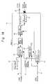
- FIG. 3is a block diagram showing a structure of a second embodiment of the capsule endoscope guidance system to which the present invention is applied;
- FIG. 4is a block diagram showing an embodiment of a capsule endoscope applied to the second embodiment of the capsule endoscope guidance system to which the present invention is applied;
- FIG. 5is a block diagram showing another embodiment of a capsule endoscope applied to the second embodiment of the capsule endoscope guidance system to which the present invention is applied;
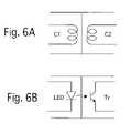
- FIGS. 6A and 6Beach shows an embodiment of a power source and signal transmission insulating structure between a capsule endoscope and capsule endoscope gripping forceps in a capsule endoscope guidance system to which the present invention is applied;
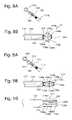
- FIGS. 7A and 7Bshow a principal portion of a third embodiment of the capsule endoscope guidance system where an capsule endoscope holder according to the present invention is applied to an electronic endoscope;
- FIGS. 8A and 8Bshow principal portions of an embodiment of a capsule endoscope holder to which the present invention is applied, in a natural state;
- FIGS. 9A and 9Bshow principal portions of an embodiment of the capsule endoscope holder in its released state
- FIG. 10is a view showing a top face of the capsule endoscope holder
- FIG. 11is a view showing a state before a capsule endoscope is connected to the capsule endoscope holder
- FIG. 12is a view showing a state where the capsule endoscope is connected to the capsule endoscope holder
- FIG. 13is a schematic diagram showing a principal portion of a fourth embodiment of the capsule endoscope guidance system including a capsule endoscope having external terminals and a capsule endoscope holder for the capsule endoscope;
- FIG. 14is a block diagram showing a principal portion of another embodiment of a capsule endoscope
- FIG. 15is a view showing a state before the capsule endoscope is connected to the capsule endoscope holder
- FIG. 16is a view showing a back face of an engaging portion of the capsule endoscope holder
- FIG. 17is a view showing a top face of the engaging portion of the capsule endoscope holder
- FIG. 18is a view showing a principal portion in a state where the capsule endoscope is engaged with the engaging portion of the capsule endoscope holder;
- FIG. 19is a plan view showing a principal portion in a state where the capsule endoscope is engaged with the engaging portion of the capsule endoscope holder;
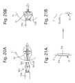
- FIG. 20Ais a view showing an embodiment of the capsule endoscope before its attachment to the capsule endoscope holder
- FIG. 20Bis a view showing the embodiment of the capsule endoscope after its attachment
- FIGS. 21A and 21Bare views respectively showing ON and OFF states of a water-proof switch of another embodiment of the capsule endoscope.
- FIG. 22is a view showing a human body for illustrating the conditions of use of a capsule endoscope.
- FIG. 1shows a basic system configuration of a capsule endoscope to which the present invention is applied.
- a capsule endoscope guidance systemincludes a capsule endoscope 10 to be swallowed by a patient, and a capsule-observation processor 50 and a monitor television TV 1 for observation which are provided outside the patient.
- the capsule endoscope 10includes, in an oval sealed (water tight/water proof) capsule container 11 , an image sensor (e.g., a CMOS or a CCD) 13 acting as image pickup device; an image pickup device driving circuit 15 for driving the CMOS image sensor 13 to perform an image pickup operation; a signal transmission section (transmission device) 17 for wirelessly transmitting an image signal captured by the CMOS image sensor 13 ; light sources (illumination device) 19 such as LEDs, for illuminating an object to be imaged; and an internal power source 21 for supplying electric power to the above-mentioned electronic members.
- the CMOS image sensor 13 and the light sources 19are placed on the shorter edge side of the sealed capsule container 11 .
- Two, three or more light sources 19are provided around the CMOS image sensor 13 .
- Light-emitting diodes (LEDs)are normally used as the light sources 19 .
- a cell, a rechargeable battery, or the like,is used as the internal power source 21 .
- the capsule endoscope 10is inserted into a body cavity while the end thereof, where the CMOS image sensor 13 and the light sources 19 are provided, is oriented forward.
- the capsule-observation processor 50includes, in a processor cabinet 51 , a signal receiving section (receiving device) 53 for receiving an image signal transmitted from the signal transmission section 17 ; and a capsule observation image processing circuit 55 .
- a video signal which is processed by the capsule observation image processing circuit 55is displayed on the monitor television TV 1 .
- a first embodiment of a capsule endoscope guidance systemwill be described with reference to a capsule endoscope guidance system shown in FIG. 2 .
- the first embodiment of the capsule endoscope guidance systemis characterized by the following structure.
- An electronic endoscopeis used for the capsule endoscope 10 as a member having an elongated flexible portion that can be guided to a desired position in a body cavity by manipulating the distal end of the electronic endoscope so that the elongated flexible portion bends in accordance with an operation at the proximal end.
- the distal end of a scope of the electronic endoscopewhich is inserted into the patient's body, is gripped with forceps provided within the endoscope.
- the electronic endoscopecan be manipulated so as to be guided to a target application-position while images produced by the capsule endoscope or the electronic endoscope are observed on the monitor.
- the components having the same functions as those of the capsule endoscope and the processor for capsule observation shown in FIG. 1are denoted by the same reference numerals in FIG. 2 , and the details thereof are herein omitted.
- the capsule endoscope guidance systemincludes a scope section (member) 100 and an endoscope processor section 200 .
- the scope section 100includes a flexible scope (elongated flexible portion) 101 , a manipulation section 103 , and a connection cable section 105 connected to the endoscope processor section 200 .
- an electronic camera 107functioning as image pickup device, an end face of a light guide 109 for illumination, and a forceps port 111 are provided.
- the electronic camera 107includes, as conventionally known, an image pickup lens serving as an imaging optical system, and for example, a CCD image sensor serving as an image pickup device.
- the electronic camera 107is operated by a driving signal transmitted from the endoscope processor section 200 via an image pickup device driving signal line 113 .
- a captured video signalis output via a video signal line 115 to the endoscope processor section 200 .
- the light guide 109guides illumination light, which is emitted from a light source 209 included in the endoscope processor section 200 , to a portion inserted into the patient's body. Thereafter, the illumination light is emitted from a distal end face of the light guide 109 , which is inserted into the patient's body.
- the forceps port 111 ais communicatively connected with a forceps insertion port 111 b provided for a portion of the scope 101 outside the patient's body.
- the capsule endoscope 10is gripped with forceps 121 , of capsule gripping forceps 120 which are inserted from the forceps insertion port 111 b , and the distal end of the forceps 121 projects from the forceps port 111 a.
- a gripping structure of the forceps 121 for the capsule endoscope 10for example, the following a mechanical engagement structure or a magnetically attracting structure can be used.
- the forceps 121are provided with claws, and the sealed capsule container 11 is provided with concave portions so as to allow the engagement of the claws with the concave portions.
- electromagnetsare provided at the distal end of the forceps 121 , and a magnetic member attracted to the electromagnets is provided on a rear end face of the sealed capsule container 11 so as to allow the magnetic member to be attracted to the electromagnets by magnetic force.
- the gripping and releasing operations of the forceps 121 for the capsule endoscope 10are effected by manipulating a handle 123 provided outside the patient's body.
- the scope section 100is connected to the endoscope processor section 200 via the connection cable section 105 .
- the endoscope processor section 200includes, inside the processor cabinet 201 , a system controller 203 for controlling the entire endoscope system; a timing controller 205 for generating a timing signal; a video signal processing circuit 207 ; the light source 209 ; and a power source section 211 for supplying electric power to these members and the electronic components of the entire system.
- the video signal processing circuit 207performs color adjustment and contour emphasis processing on a video signal, which is input through a video signal line 115 , so as to convert the video signal into a video signal that can be displayed on a monitor television TV 2 or a video signal that can be processed in a data system or the like.
- the system controller 203controls the operations of the electronic camera 107 , the video signal processing circuit 207 or the like, based on a timing signal (a clock or a pulse) generated by the timing controller 205 . For instance, the system controller 203 generates an image pickup device driving signal based on the timing signal so as to control an imaging operation of the electronic camera 107 in accordance with the image pickup device driving signal.
- a timing signala clock or a pulse
- Light emitted from the light source 209is incident on the end face of the light guide 109 to exit from the tip end face of the light guide 109 which is situated at the distal end of the scope 101 , thereby illuminating the inside of a body cavity.
- the electronic camera 107is driven under this illumination.
- a video signal captured by the electronic camera 107is input to the endoscope processor section 200 via the video signal line 115 .
- the light source 209 of the endoscope processor section 200is equipped with a shutter 209 S for switching the ON/OFF control of the illumination without directly switching the ON/OFF control of the light source.
- the video signal output from the video signal processing circuit 207is input to a video input terminal of the monitor television TV 2 so as to be displayed on the monitor television TV 2 .
- the capsule endoscope guidance system of the first embodimentis used in the following manner.
- the scope section 100is connected to the endoscope processor section 200 , and the forceps 121 are inserted through the forceps insertion port 111 b to project beyond the forceps port 111 a , thereby gripping the capsule endoscope 10 .
- the capsule-observation processor 50 and the monitor television TV 1are turned ON.
- a video signal wirelessly transmitted from the signal transmission section 17is received by the capsule-observation processor 50 so as to be viewed on the monitor television TV 1 .
- the usermanipulates the scope section 100 to insert the capsule endoscope 10 through the patient's mouth.
- the usermanipulates the scope section 100 while observing images displayed on the monitor television TV 1 so as to guide the capsule endoscope 10 to a target application-position.
- the userWhen the user confirms that the capsule endoscope 10 reaches the target application-position, the user manipulates the handle 123 so as to release the capsule endoscope 10 from the forceps 121 to leave the capsule endoscope 10 at the target application-position. Thereafter, since the user can view the images produced by the electronic camera 107 of the scope section 100 on the monitor television TV 2 , the user can manipulate the scope section 100 while the user observes the images on the monitor television TV 2 , so as to safely pull out the scope 101 from the patient's body cavity.
- the capsule endoscope 10continues transmitting images of the inner face of a lumen, which are produced by the CMOS image sensor 13 , via the signal transmission section 17 , while being propelled by peristalsis of the small intestine and the like.
- the capsule endoscope 10since it is ensured that the capsule endoscope 10 is guided to a target application-position by using the existing scope section 100 , endoscope processor section 200 , and capsule gripping forceps 120 , a state of the target application-position can be reliably observed.
- the capsule endoscope 10can be guided to a target application-position distant from the patient's mouth, such as inside the small intestine, while the user is observing images produced by the electronic camera 107 of the scope section 100 on the monitor television TV 2 rather than images produced by the CMOS image sensor 103 of the capsule endoscope 10 .
- the electronic endoscopeis used as an endoscope for guiding the capsule endoscope 10 in the first embodiment of the capsule endoscope guidance system
- an optical endoscopecan be used instead.
- any type of endoscopecan be used as long as the endoscope is capable of gripping the capsule endoscope 10 to guide the capsule endoscope 10 to a target application-position inside a lumen.
- the capsule endoscope 10normally includes a cell or rechargeable battery as an internal power source.
- the capsule endoscope 10is extremely compact, the size of the battery or cell is correspondingly limited, which prevents the capacity from being sufficiently increased. Therefore, there is a possibility that the capacity of the battery/cell may run out from the capsule endoscope 10 being inserted to being excreted.
- a second embodiment of the capsule endoscope guidance systemprovides a capsule endoscope guidance system so that an internal power source of the capsule endoscope 10 is used as little as possible during the guidance of the capsule endoscope 10 to a target position.
- the second embodiment of the capsule endoscope guidance systemwill be described with reference to FIGS. 3 to 6B .
- the same components and the components having the same functions as those of the first embodiment of the capsule endoscope guidance systemare denoted by the same reference numerals.
- the capsule gripping forceps 120include a driving power source line 125 , an image pickup device driving signal line 127 , and a video signal line 129 .
- the driving power source line 125 , the image pickup device driving signal line 127 , and the video signal line 129serve to connect the capsule-observation processor 50 to the capsule endoscope 10 .
- each of the driving power source line 125 , the image pickup device driving signal line 127 , and the video signal line 129is connected to each corresponding circuit included in the capsule-observation processor 50 .
- each of the driving power source line 125 , the image pickup device driving signal line 127 , and the video signal line 129is connected to each of corresponding circuits included in the capsule endoscope 10 .
- the respective corresponding circuits of the capsule-observation processor 50 and the capsule endoscope 10are connected to each other through the respective driving power source line 125 , the image pickup device driving signal line 127 , and the video signal line 129 .
- the capsule-observation processor 50includes a system controller 57 for controlling the capsule endoscope guidance system, a timing controller 59 , and a capsule driving power source 61 .
- the system controller 57generates an image pickup device driving signal based on a timing signal generated by the timing controller 59 so as to drive the CMOS image sensor 13 of the capsule endoscope 10 via the image pickup device driving signal line 127 .
- the capsule driving power source 61transfers capsule driving electric power to the capsule endoscope 10 via the driving power source line 125 so as to operate each of the circuits in the capsule endoscope 10 .
- a video signal of the image captured by the CMOS image sensor 13 of the capsule endoscope 10is input to the capsule observation image processing circuit 55 via the video signal line 129 .
- the capsule observation image processing circuit 55performs predetermined correction on the input signal so as to convert the input signal to a video signal which is compatible for inputting to the monitor television TV 2 .
- the obtained video signalis then output to the image switching device 301 .
- the image switching device 301performs a switching operation based on an image switching signal output from the system controller 57 via the image switching signal line 305 .
- the system controller 57receives a system control signal from the system controller 203 of the endoscope processor section 200 via the system control signal line 303 so as to control a switching operation so as to either display a video signal output from the endoscope processor section 200 (a video signal from the electronic camera 107 ) or display a video signal from the CMOS image sensor 13 .
- FIG. 4A more detailed structure of the capsule endoscope 10 used in the second embodiment is shown in FIG. 4 .
- the same components and the components having the same functions as those of the capsule endoscope 10 shown in FIGS. 1 and 2are denoted by the same reference numerals in FIG. 4 .
- the capsule endoscope 10 in this embodimentincludes a power source switching circuit 23 and an operation switching circuit 25 .
- the power source switching circuit 23switches an operation power source of built-in circuits between the internal power source 21 and an external power source.
- the operation switching circuit 25switches an operation mode of the built-in circuits between an internal power source mode and an external power source mode.
- the internal power source modeis a mode in which the built-in circuits are operated by electric power supplied from the internal power source 21 .
- the image pickup device driving circuit 15is intermittently activated to intermittently operate the CMOS image sensor 13 via the image pickup device driving signal switching circuit (driving signal output device) 27 so as to transmit a video signal output from the CMOS image sensor 13 to the signal transmission section 17 via the video signal output switching circuit 29 where the video signal is modulated to a wireless signal so as to be output therefrom.
- the internal power source modeis a normal operation mode of the capsule endoscope 10 .
- the external power source modeis a mode in which the built-in circuits are operated in response to the supply of driving electric power (external power source) via the driving power source line 125 .
- the power source switching circuit 25is switched from an internal power source operation to an external power source operation.
- the power source switching circuit 23switches OFF the internal power source 21 so as to enter the external power source mode in which an external power source is supplied to each of the included components and circuits.
- the image pickup device driving signal switching circuit 27is switched to perform an external image pickup device driving signal operation so that an image pickup device driving signal is input via the image pickup device driving signal line 127 to the CMOS image sensor 13 .
- the CMOS image sensor 13performs an image pickup operation.
- a video signal output from the CMOS image sensor 13is output via the video signal output switching circuit 29 to the external video signal line 129 (capsule observation image processing circuit).
- the external power source modeis an operation mode in which the capsule endoscope 10 is being gripped by the forceps 121 .
- the capsule endoscope 10When the capsule endoscope 10 is gripped with the forceps 121 , the capsule endoscope 10 receives driving electric power (external power source) supplied via the driving power source line 125 as well as an image pickup device driving signal supplied via the image pickup device driving signal line 127 so as to start the operation in the external power source mode. Subsequently, a video signal of the image captured by the CMOS image sensor 13 is output via the video signal line 129 to the capsule-observation processor 50 .
- driving electric powerexternal power source
- an image pickup device driving signalsupplied via the image pickup device driving signal line 127 so as to start the operation in the external power source mode.
- a video signal of the image captured by the CMOS image sensor 13is output via the video signal line 129 to the capsule-observation processor 50 .
- the capsule-observation processor 50supplies driving electric power for the connected capsule gripping forceps 120 from the capsule driving power source 61 to the driving power source line 125 , and the capsule-observation processor 50 supplies an image pickup device driving signal from the timing controller 59 to the image pickup device driving signal line 127 . Thereafter, a video signal output from the video signal line 129 is input to the capsule observation image processing circuit 55 so as to be output to the image switching signal line 305 as a capsule observation video signal. Subsequently, the capsule observation video signal is input via the image switching device 301 to the monitor television TV 2 where an image is viewed on the screen.
- the usermanipulates the scope section 100 with viewing an observation image displayed on the monitor television TV 2 to guide the capsule endoscope 10 to a target application-position.
- the usermanipulates the handle 123 to release the capsule endoscope 10 from the forceps 121 so as to leave the capsule endoscope 10 at the target application-position.
- the useroperates the image switching device 301 so that the image produced by the electronic camera 107 can be displayed on the monitor television TV 2 . Accordingly, the user can safely pull out the scope 101 from the patient's body cavity while observing the images on the monitor television TV 2 .
- the userUpon the user taking the scope 101 out of the patient, the user operates the image switching device 301 so that the images produced by the capsule endoscope 10 are displayed on the monitor television TV 2 .
- the power sourceis switched to the internal power source 21 so that the operation switching circuit 25 is switched to be operated in the internal power source operation mode, thereby starting its own capsule endoscope operation. Accordingly, since the capsule endoscope 10 can start its own capsule endoscope operation, a video signal produced by the CMOS image sensor 13 can be displayed on the monitor television TV 2 .
- FIG. 5is a block diagram showing principal circuits of another embodiment of the capsule endoscope 10 .
- the operation switching circuit 25detects the supply of driving electric power so that the power source switching circuit 23 switches the operation mode from the internal power source operation mode to the external power source operation mode.
- the mode switchingis detected by a forceps connection monitoring circuit (detection device) 30 so that the power source switching circuit 23 switches its power source.
- FIGS. 6A and 6BExamples of an insulating connection structure between the driving power source line 125 , the image pickup device driving signal line 127 and the video signal line 129 , and the capsule endoscope 10 are shown in FIGS. 6A and 6B .
- a power source transfer systemis a structure utilizing an electromagnetic induction effect of a coil.
- a primary coil C 1 included in a tip portion of the driving power source line 125 and a secondary coil C 2 included in the capsule endoscope 10are brought close to each other so that an alternating current flowing through the primary coil C 1 generates an induced current in the secondary coil C 2 .
- such a structureis utilized as an insulating structure for transferring driving electric power and an image pickup device driving signal.
- a video signal transfer systemis a structure utilizing optical communication using a light-emitting diode LED on the output side thereof and a photo-transistor Tr on the input side thereof, as shown in FIG. 6B .
- this structureis used as an insulating structure including the light-emitting diode LED in the capsule endoscope 10 so as to transmit a video signal output from the video signal output switching circuit 29 to the video signal line 129 .
- the present inventionis also applicable to an optical fiber constituted by an optical element.
- an optical fibercan be used as an electronic endoscope using the CMOS image sensor 13 of the capsule endoscope 10 .
- a capsule endoscope holder applicable to the above-described capsule endoscope guidance systemwill be described. Since the basic structures of a capsule endoscope, an electronic endoscope and a processor section for endoscope are the same as those of the capsule endoscope 10 , the scope section 100 and the endoscope processor section 200 that have been already described based on FIGS. 1 to 6B , the description thereof is herein omitted. Furthermore, the same components and the components having the same functions as those described above are denoted by the same reference numerals, and the description thereof is herein omitted.
- FIG. 7Ais a front view showing a state where the capsule endoscope 10 is held at the distal end of the scope 101 via capsule connecting forceps 150 .
- FIG. 7Bis an enlarged view of a connected portion between the capsule endoscope 10 and the capsule connecting forceps 150 .
- the forceps port 111 ais in communication with the forceps insertion port 111 b provided for a portion of the scope 101 outside the patient's body via a pipe (not shown).
- An engagement holder (openable/closeable engagement member) 151 for connecting and holding the capsule endoscope 10is attached to the distal end of the capsule connecting forceps 150 .
- the engagement holder 151 inserted from the forceps insertion port 111 bprojects beyond the forceps port 111 a .
- the capsule endoscope 10is connected to the thus projecting engagement holder 151 .
- the capsule endoscope 10is held at the distal end of the scope 101 , which is inserted into the patient's body.
- the connecting and releasing operations of the capsule endoscope 10 via the engagement holder 151are performed by manipulation of a manipulation section (removal/attachment manipulation device) 161 that is provided externally (i.e., outside the patient's body).
- a connection structure between the capsule connecting forceps 150 and the capsule endoscope 10will be described in further detail with reference to FIGS. 8A to 12 .
- An engagement hole 12 for connection(see FIG. 11 ) is formed in the center of a rear end face of the sealed capsule container 11 of the capsule endoscope 10 , which is opposite to the end face provided with the CMOS image sensor 13 and the light source 19 .
- the engagement hole 12has a narrowed opening 12 a and an enlarged hole 12 b which enlarges from the opening 12 a toward the base thereof.
- An inclined face 12 c extending from the opening 12 a toward the base thereofis formed between the opening 12 a and the enlarged hole 12 b .
- the engagement hole 12 in this embodimentis formed so that the opening 12 a is sealed by an edge of the opening 12 a and an outer circumferential face of a forceps pipe 153 in close contact with each other when the forceps pipe 153 is inserted into the opening 12 a .
- the forceps pipe 153is formed so as to serve as a sealing plug of the opening 12 a.
- the capsule connecting forceps 150are provided with the engagement holder 151 to which a quadric crank chain mechanism is applied for connecting and holding the capsule endoscope 10 .
- a cable 157is slidably inserted through the forceps pipe 153 , and the capsule endoscope 10 is connected and held at the distal end of the forceps pipe 153 .
- the engagement holder 151includes four connecting plates 158 a , 158 b , 158 c and 158 d having identical widths and lengths, as principal connecting members.
- the connecting plates 158 a to 158 dare connected to each other in a circular form so that adjacent two plates are connect with a pair by four shafts 159 a , 159 b , 159 c , and 159 d .
- the shaft 159 ais a fixed shaft fixed to a projecting piece 154 provided on the distal end of the forceps pipe 153 .
- the shaft 159 c opposed to the fixed shaft 159 aserves as a driving shaft fixed to the tip of a driving plate 155 (see FIG. 10 ) insertably housed within the forceps pipe 153 .
- the driving plate 155serves as a plate-like member that movably projects from the distal end of the forceps pipe 153 in projecting and retracting directions.
- the opposed shafts 159 b and 159 d between these shafts 159 a and 159 cserve as moving shafts.
- the distance between the moving shafts 159 b and 159 dvaries in correspondence with a variation in distance between the shafts 159 a and 159 c .
- the connecting plates 158 a and 158 d and the moving shafts 159 b and 159 dconstitute an engaging portion.
- An end of the driving plate 155which is provided in the forceps pipe 153 , is connected to one end (distal end) of the cable 157 which is slidably inserted into the forceps pipe 153 .
- the other end (proximal end) of the cable 157is connected to the handle 163 inserted from the end of the forceps pipe 153 , which is provided outside the patient's body.
- the manipulation portion 161is slidably attached to a portion of the forceps pipe 153 which is provided outside the patient's body.
- a tubular flange lever (movement manipulation member) 165is connected to the end of the forceps pipe 153 , which projects from the manipulation portion 161 , outside the patient's body so as to be slidable with respect to the manipulation section 161 .
- the manipulation portion 161is fitted and held into the forceps insertion port 111 b while the forceps pipe 153 is inserted through the forceps insertion port 111 b with the engagement holder 151 projecting from the forceps port 111 a .
- the length of the capsule connection forceps 150is set so as to match a length from the forceps insertion port 111 b to the forceps port 111 a.
- the handle 163 and the manipulation portion 161are connected to each other so as to prevent relative movement thereof, and as a result, the distance between the handle 163 and the flange lever 165 is increased between the manipulation portion 161 or the handle 163 and the flange lever 165 so as to bias the driving plate 155 into the forceps pipe 153 . Therefore, the engagement holder 151 is held in a normally open state ( FIGS. 8B and 12 ).
- the forceps pipe 153 and the driving plate 155relatively move, i.e., the driving plate 155 moves so as to project from/be drawn back into the forceps pipe 153 so that the connecting shaft 159 c moves away from/approaches the connecting shaft 159 a , respectively.
- the distance between the connecting shafts 159 b and 159 dis reduced or increased.
- the userputs his/her thumb into the handle 163 , holds the flange lever 165 with an index finger and a middle finger, and then brings the thumb, the index finger, and the middle finger close to each other to pull the flange lever 165 toward the handle 163 . Accordingly, the forceps pipe 153 is drawn back so that the driving plate 155 projects from the forceps pipe 153 .
- the driving plate 155since the driving plate 155 is biased so as to be drawn back into the forceps pipe 153 , the driving plate 155 is drawn back into the forceps pipe 153 due to biasing force of a spring 162 in a natural state, thereby opening out the engagement holder 151 in a direction perpendicular to the direction of movement of the driving plate 155 ( FIGS. 8B and 12 ).
- This capsule endoscope connection mechanismis used in the following manner.
- the engagement holder 151is inserted through the forceps insertion port 111 b into the scope section 100 connected to the endoscope processor section 200 so as to project from the forceps port 111 a .
- the flange lever 165is pulled so as to bring the engagement holder 151 into a closed (folded, or reduced in width) state ( FIGS. 9A , 9 B and 11 ).
- the manipulation portion 161is provided with a lock mechanism in such a manner that a pull of the flange lever 165 locks the flange lever 165 to prevent the flange lever 165 from projecting from the manipulation portion 161 by the biasing force of the spring 162 , and unlocking allows the flange lever 165 to move so that the engagement holder 151 projects due to the biasing force of the spring 162 , only one pull of the flange lever 165 allows the grasp to be released from the flange lever 165 when the capsule endoscope 10 is to be attached.
- the biasing direction of the spring 162 and the direction in which the lock mechanism actscan be opposite to each other.
- the engagement holder 151can be always biased so as to project to be closed by the spring 162 . In this case, when the flange lever 165 is pulled, the flange lever 165 is locked by the lock mechanism to maintain the engagement holder 151 in a opened state.
- the engagement holder 151 in a closed stateis inserted into the engagement hole 12 of the capsule endoscope 10 , as shown in FIG. 11 . Thereafter, the force for holding the handle 163 is released while the end of the engagement holder 151 is inserted to abut against the base of the engagement hole 12 , thereby the engagement holder 151 is opened (increasing in width) via the biasing force of the spring 162 ( FIG. 12 ). Namely, since the driving plate 155 moves so as to be drawn back into the forceps pipe 153 , the distance between the moving shafts 159 b and 159 d is increased, thereby widely increasing an angle formed by the connecting plates 158 a and 158 d .
- the driving plate 155presses the inclined face 12 c between the opening 12 a and the enlarged hole 12 b (so as to press the driving plate 155 against the base of the enlarged hole 12 b ) thereby preventing the engagement holder 151 from being pulled out of the opening 12 a .
- the connecting plates 158 a to 158 dare opened out within the enlarged hole 12 b to be larger than the diameter of the opening 12 a .
- the engagement holder 151is brought into a connected state so as not to be pulled out of the opening 12 a .
- the capsule endoscope 10is connected and held at the tip of the scope 101 that is inserted into the patient's body while preventing the clattering movement by the force of the connecting plates 158 a and 158 d and the driving plate 155 for pressing the inner surface of the enlarged hole 12 b .
- the engagement hole 12is formed outside the sealed capsule container 11 so as to maintain a sealed state in the capsule.
- the CMOS image sensor 13performs an image pickup operation.
- a captured video signalis wirelessly transmitted by the signal transmission section 17 to be received by the signal receiving section 53 of the capsule-observation processor 50 .
- the video signalis subjected to predetermined processing in the capsule observation image processing circuit 55 so as to be viewed on the monitor television TV 1 .
- the userinserts the capsule endoscope 10 through the patient's mouth.
- the usermanipulates the scope 101 to guide the capsule endoscope 10 to a target position while viewing the images displayed on the screen of the monitor television TV 1 .
- the userpulls the flange lever 165 to release the connection between the engagement holder 151 and the capsule endoscope 10 .
- the driving plate 155moves to project from the forceps pipe 153 so that the connecting plates 158 a to 158 d change an elongated form.
- the base of the enlarged hole 12 bis pressed by portions (the distal end of the driving plate 155 ) of the connecting plates 158 b and 158 c , which are connected by the shaft 159 c .
- the engagement holder 151is pulled out of the enlarged hole 12 b while pushing the capsule endoscope 10 .
- the capsule endoscope 10is left at the target position of the patient ( FIG. 22 ).
- the capsule endoscope 10is advanced in an excreting direction by peristalsis of the intestines while transmitting a video signal of images captured by the CMOS image sensor 13 .
- the capsule endoscope 10is ultimately excreted from the patient's body.
- the capsule endoscope 10can be easily and reliably connected to the engagement holder 151 of the capsule connection forceps 150 , and the capsule endoscope 10 can be easily and reliably guided to a target position while being held at the tip of the scope 101 . Moreover, after the capsule endoscope 10 is guided to the target position, mere manipulation of the handle 163 of the capsule connection forceps 150 allows the connection with the capsule endoscope 10 to easily and reliably release so as to leave the capsule endoscope 10 at the target position.
- the present inventionhas been applied to the electronic scope corresponding to a type of endoscope in the illustrated embodiments, the present invention is not limited to the endoscope.
- the present inventionis also applicable to a member, insertable into the patient's body, having an elongated flexible portion that can be freely manipulated in a curved manner from one end thereof. Such a member can have a smaller width than that of the endoscope.
- a fourth embodiment of the capsule endoscope guidance systemwill be described with reference to FIGS. 13 to 21 .
- Basic structures of a capsule endoscope, an electronic endoscope, and a processor section for endoscope in the following illustrated embodimentare the same as those of the capsule endoscope 10 , the scope section 100 , and the endoscope processor section 200 , which have been already described based on FIGS. 1 to 6 .
- a structure of a capsule endoscope holderis the same as that of the capsule endoscope holder shown in FIGS. 7 to 12 , the same components and the components having the same functions as those of the capsule endoscope holder shown in FIGS. 7 to 12 are denoted by the same reference numerals, therefore the descriptions thereof are omitted.
- a structure of the capsule-observation processor 50is the same as that of the capsule-observation processor 50 shown in FIG. 3 .
- an image pickup device driving signal output from the timing controller 59is transmitted via the image pickup device driving signal line 169 to the engagement holder 151 .
- Capsule driving electric power output from the capsule driving power source 61is transferred via the driving power source line 167 to the engagement holder 151 .
- a video signal of images captured by the CMOS image sensor 13 of the capsule endoscope 10is input via a video signal line 171 to the capsule observation image processing circuit 55 .
- the basic structure of the embodiment of the capsule endoscope 10 shown in FIG. 14is the same as that of the capsule endoscope 10 shown in FIG. 4 .
- the power source switching circuit 23switches an operational power source of the built-in circuits between the internal power source 21 and an external power source.
- the operation switching circuit 25switches an operation mode of the built-in circuits between the internal power source mode and the external power source mode.
- the internal power source modeis also a normal operation mode of the capsule endoscope 10 , which has been already described.
- the external power source modeis a mode in which the capsule endoscope 10 operates in response to supply of driving electric power (external power source) via an external power source input terminal 33 .
- driving electric powerexternal power source
- the operation switching circuit 25switches its operation from the internal power source operation to the external power source operation.
- the power source switching circuit 23switches OFF the internal power source 21 so as to operate in the external power source mode for supplying the external electric power to each of the included members and circuits.
- the image pickup device driving signal switching circuit 27is switched to perform an external image pickup device driving signal operation so that an image pickup device driving signal is input from the image pickup device driving signal line 169 a via an external driving signal input terminal 35 to the CMOS image sensor 13 .
- the CMOS image sensor 13performs an image pickup operation.
- a video signal from the CMOS image sensor 13is output from an external video signal output terminal 37 via the video signal output switching circuit 29 to the external video signal line 171 a (capsule observation image processing circuit).
- the external power source modeis an operation mode in which the capsule endoscope 10 is connected and held by the capsule connection forceps 150 .
- a basic structure of the capsule connection forceps 150 used in this embodimentis the same as that shown in FIGS. 7 to 12 .
- the engagement hole 12is formed in the sealed capsule container 11 of the capsule endoscope 10 (see FIG. 15 ).
- the engagement hole 12has the narrowed opening 12 a and the enlarged hole 12 b that increases in diameter from the opening 12 a toward the base thereof.
- the inclined face 12 c extending from the opening 12 a toward the base of the engagement hole 12is formed between the opening 12 a and the enlarged hole 12 b .
- the engagement hole 12 in this embodimentis formed so that the opening 12 a is sealed by the edge of the opening 12 a and the outer circumferential face of the forceps pipe 153 in close contact with each other when the forceps pipe 153 is insertable and is being inserted into the opening 12 a .
- the forceps pipe 153is formed so as to serve as a sealing plug of the opening 12 a.
- the external power source input terminal 33 , the external driving signal input terminal 35 and the external video signal output terminal 37are provided in an exposed state as external terminals.
- the external power source input terminal 33 , the external driving signal input terminal 35 and the external video signal output terminal 37extend in the same direction as that of pulling/inserting direction of the engagement holder 151 from the engagement hole 12 , and the external power source input terminal 33 , the external driving signal input terminal 35 and the external video signal output terminal 37 are arranged in a direction orthogonal to this direction at predetermined intervals.
- the external power source input terminal 33 , the external driving signal input terminal 35 and the external video signal output terminal 37are connected via a water-proof switch 31 to the respective circuits in the sealed capsule container 11 (see FIGS. 20A through 21B ).
- the water-proof switch 31includes, as an operational portion, a normally open terminal within a water-proof cover exposed at the base of the enlarged hole 12 b .
- the external power source input terminal 33 , the external driving signal input terminal 35 and the external video signal output terminal 37 and the respective circuits in the sealed capsule container 11are normally in an isolated state.
- the water-proof switch 31When the engagement holder 151 is inserted into the engagement hole 12 , the water-proof switch 31 is pressed by the end of the driving plate 155 . Furthermore, the connecting plates 158 a to 158 d open outwards so that the engagement holder 151 is connected into the engagement hole 12 so as not to come off from the engagement hole 12 . In such a state, the water-proof switch 31 is pressed strong enough to be switched ON ( FIG. 20B ). This ON state is maintained while the engagement holder 151 is engaged with the engagement hole 12 .
- terminals 167 a , 169 a , and 171 awhich extend in a longitudinal direction, are provided on one face of the driving plate 155 of the engagement holder 151 , whose face is opposite to the face where the shafts 159 a to 159 d are attached.
- the terminals 167 a , 169 a , and 171 aare respectively connected to the lines 167 , 169 , and 171 .
- the terminals 167 a , 169 a , and 171 aare brought into a sliding contact with the corresponding external power source input terminal 33 , the external driving signal input terminal 35 and the external video signal output terminal 37 , respectively, when the engagement holder 151 is inserted into the engagement holder 12 for connection. In this manner, the terminals 167 a , 169 a , and 171 a maintain an electrically conductive state when connected.
- This capsule endoscope connection mechanismis used in the following manner.
- the engagement holder 151is inserted through the forceps insertion port 111 b into the scope section 100 connected to the endoscope processor section 200 so as to project from the forceps port 111 a .
- the flange lever 165is pulled so as to bring the engagement holder 151 into a closed (reduced in width) state ( FIGS. 5 , 15 , and 20 A).
- the engagement holder 151 in a closed stateis inserted into the engagement hole 12 of the capsule endoscope 10 . Thereafter, the force for holding the handle 163 is released while the end of the engagement holder 151 is inserted into the engagement hole 12 so as to abut against the base of the engagement hole 12 , thereby opening (increasing in width) the engagement holder 151 by the biasing force of the spring 162 ( FIGS. 18 and 20B ).
- the driving plate 155moves so as to be drawn back into the forceps pipe 153 , the distance between the connecting shafts 159 b and 159 d is increased to widely open the connecting plates 158 a and 158 d , pressing the boundary inclined face 12 c between the opening 12 a and the enlarged hole 12 b .
- the end of the driving plate 155is pressed against the water-proof switch 31 attached to the bottom of the enlarged hole 12 b , and the engagement holder 151 is prevented from being pulled out of the opening 12 a .
- the connecting plates 158 a to 158 dare opened inside within the enlarged hole 12 b to be larger than the diameter of the opening 12 a , thereby providing a connected state for preventing the connecting plates 158 a to 158 d from being pulled out of the opening 12 a .
- a clattering movementis prevented by the force of the connecting plates 158 a and 158 d and the driving plate 155 for pushing the inclined face 12 c and the bottom of the enlarged hole 12 b .
- the capsule endoscope 10is connected and held at the distal end of the scope 101 that is inserted into the patient's body while the water-proof switch 31 is in an ON state.
- the tip of the forceps pipe 153is fitted into the opening 12 a in a liquid-proof state, thereby sealing the enlarged hole 12 b.
- the water-proof switch 31includes a stretchable operational portion 31 a exposed in the enlarged hole 12 b , and a contact portion 31 b positioned within the capsule.
- the operational portion 31 aprevents water from entering the capsule.
- An OFF state of the water-proof switch 31is shown in FIGS. 20A and 21A , whereas an ON state thereof is shown in FIGS. 20B and 21B .
- the terminals 167 a , 169 a , and 171 a of the driving plate 155are electrically conductive with the external power source input terminal 33 , the external driving signal input terminal 35 and the external video signal output terminal 37 , respectively, so that the capsule endoscope 10 can be switched to perform its operation in the external power source mode. Namely, in response to supply of driving electric power (external power source) via the driving power source line 167 and the terminal 167 a and the external power source input terminal 33 , the operation mode of the capsule endoscope 10 is switched to the external power source mode.
- driving electric powerexternal power source
- a video signal of images captured by the CMOS image sensor 13is output to the capsule-observation processor 50 via the external video signal output terminal 37 and the terminal 171 a , and the video signal line 171 .
- the capsule-observation processor 50supplies driving electric power from the capsule driving power source 61 to the driving power source line 167 while supplying an image pickup device driving signal from the timing controller 59 to the image pickup device driving signal line 169 . Subsequently, a video signal is input from the video signal line 171 to the capsule observation image processing circuit 55 , from which the video signal is output as a capsule observation video signal 55 S.
- the capsule observation video signal 55 Spasses through the image switching device 301 to be displayed as an image on the screen of the monitor television TV 2 .
- the userinserts the capsule endoscope 10 through the patient's mouth.
- the usermanipulates the scope 101 to guide the capsule endoscope to a target position while viewing the images on the screen of the monitor television.
- the userpulls the flange lever 165 to release the connection between the engagement holder 151 and the capsule endoscope 10 .
- the driving plate 155moves so as to project from the forceps pipe 153 , so that the connecting plates 158 a to 158 d changes to an elongated form whereby the distance between the shafts 159 a and 159 b is reduced.
- the engagement holder 151is pulled out of the enlarged hole 12 b while pressing the bottom of the enlarged hole 12 b with the connected portions of the connecting plates 158 b and 158 c through the shaft (the tip of the driving plate 155 ) to push the capsule endoscope 10 .
- the capsule endoscope 10is left at the target position of a patient ( FIG. 22 ).
- the driving plate 155is separated from the water-proof switch 31 , and the external power source input terminal 33 , the external driving signal input terminal 35 and the external video signal output terminal 37 are isolated from the respective circuits in the capsule container 11 .
- the external power sourceis replaced by the internal power source 21 so that the operation switching circuit 25 switches its operation mode to the internal power source operation mode to start the original capsule endoscope operation. Since the external power source input terminal 33 , the external driving signal input terminal 35 and the external video signal output terminal 37 are isolated from the circuits in the capsule container 11 after the capsule endoscope 10 is left at the target position in the above-described manner, electrical leakage does not occur therein.
- the capsule endoscope 10is carried in an excreting direction by peristalsis of the intestines while transmitting a video signal of images captured by the CMOS image sensor 13 .
- the capsule endoscope 10is ultimately excreted from the patient's body.
- the capsule endoscope 10is held by the engagement holder 151 of the capsule connection forceps 150 .
- the external power source input terminal 33 , the external driving signal input terminal 35 and the external video signal output terminal 37can be easily and reliably connected to the terminals 167 a , 169 a , and 171 a , respectively. Therefore, the capsule endoscope 10 is held at the distal end of the scope 101 so as to easily and reliably guide the capsule endoscope 10 to a target position while electric power is being supplied to the capsule endoscope 10 .
- the present inventionis applied to the electronic scope which is one type of endoscope in the illustrated embodiment, the present invention is not limited thereto, and can be applied to a member insertable into the patient's body, which has an elongated flexible portion allowing free manipulation in a curved manner from one end thereof.
- this memberwould be electrically conductive with the external power source input terminal 33 , the external driving signal input terminal 35 and the external video signal output terminal 37 of the capsule endoscope so as to be capable of giving and receiving electric power and signals.
- Such a memberis desirable because it can have a smaller diameter than that of the endoscope.
- the external power source input terminal 33 , the external driving signal input terminal 35 , and the external video signal output terminal 37are shown as external terminals of the capsule endoscope 10 in the illustrated embodiment, the external terminals are not limited thereto.
- the external terminals of the capsule endoscope 10can be provided on the bottom of the engagement hole, and the terminal on the engagement holder 151 side may alternatively be provided on the tip end face of the driving plate 155 .
- the engagement holder 151is constructed from four connecting plates 158 a to 158 d connected in a circular manner by overlapping their ends to form a quadrangle so as to constitute a thin quadric crank chain mechanism with the shafts 159 a through 159 d orthogonally crossing the faces of the connecting plates
- the connecting plates 158 a to 158 dcan be connected with each other in a circular manner so that their shorter sides are opposed to each other to form a thick quadric crank chain mechanism by shafts extending along the shorter sides.
- the connecting platescan be bar-like members instead of being the plate-like members.
- connecting plates 158 a to 158 dare identical with each other in the illustrated embodiment, the lengths may be varied. Moreover, if the connecting plates 158 a and 158 d are shorter than the connecting plates 158 b and 158 c , or moving shafts 159 b and 159 d are provided in the middle of the connecting plates 158 a and 158 d to reduce the length between the fixed shaft 159 a and the moving shaft 159 b , and that of between the fixed shaft 159 a and the moving shaft 159 d , the degree of opening and closing between the connecting plates 158 a and 158 d (a rate of change in narrow angle) in response to a stroke of the driving plate 155 is increased.
- the quadric crank chain mechanism applied to the structure of the engagement holder 151 in the illustrated embodimentis not limited thereto. Any structure of the engagement holder 151 is applicable as long as the engagement holder 151 is insertable into and removable from the engagement hole of the capsule endoscope so as to be opened out within the inserted state to connect and hold the capsule endoscope; for example, a balloon-like structure is applicable.
- the capsule endoscopecan be guided to a desired target application-position with the endoscope.
- a usercan quickly guide and leave the capsule endoscope at a position to which the user wishes to use the capsule endoscope, or the vicinity thereof.
- the capsule endoscope holding deviceBy providing power source supply device and image pickup device driving signal output device for the capsule endoscope holding device, it is not necessary to use an internal power source of the capsule endoscope while the capsule endoscope is being held by the capsule endoscope holding device. Moreover, if the capsule endoscope holding device is equipped with the video signal transmission device as described above, a video signal of images captured by the image pickup device included in the capsule endoscope can be output to, for example, an external monitor television to be displayed thereon. Thus, the capsule endoscope can be more precisely guided to a target position.
- the capsule endoscopecan be held at the tip of the endoscope, which is inserted in the patient's body.
- a power source and a driving pulsecan be supplied so that a video signal of images captured by a camera included in the capsule endoscope is output to external equipment.
Landscapes
- Health & Medical Sciences (AREA)
- Life Sciences & Earth Sciences (AREA)
- Surgery (AREA)
- Engineering & Computer Science (AREA)
- Radiology & Medical Imaging (AREA)
- Heart & Thoracic Surgery (AREA)
- Biophysics (AREA)
- Nuclear Medicine, Radiotherapy & Molecular Imaging (AREA)
- Optics & Photonics (AREA)
- Pathology (AREA)
- Veterinary Medicine (AREA)
- Public Health (AREA)
- Biomedical Technology (AREA)
- Physics & Mathematics (AREA)
- Medical Informatics (AREA)
- Molecular Biology (AREA)
- Animal Behavior & Ethology (AREA)
- General Health & Medical Sciences (AREA)
- Computer Networks & Wireless Communication (AREA)
- Multimedia (AREA)
- Signal Processing (AREA)
- Endoscopes (AREA)
Abstract
Description
1. Field of the Invention
The present invention relates to a capsule endoscope having external terminals, and a capsule endoscope guidance system and a capsule endoscope holder which are capable of holding such a capsule endoscope at a distal end of an endoscope, and the like, for guidance thereof.
2. Description of the Related Art
A capsule endoscope, which has been recently developed, captures images of the inside of a lumen (inside a patient's body) with an electronic camera equipped with a built-in image pickup device such as a CMOS image sensor while illuminating the inside of the lumen with a light source housed within a sealed capsule container. Thereafter, the capsule endoscope wirelessly transmits the captured image signals outside the patient's body. A processor for capsule observation, which is provided externally, receives the transmitted image signals so as to display the images on a screen of a monitor television or the like (JP 2001-245844 and the like). A user views this monitor television screen so as to observe and examine the state of a body cavity of the patient. Electronic parts in the capsule endoscope, such as the light source and the image pickup device, are powered by a battery included within the capsule container as a power source.
Such a capsule endoscope is orally inserted into the patient by swallowing the capsule endoscope so as to move from the esophagus through to the stomach, the duodenum and subsequently the small intestine. In the body cavity, the capsule endoscope is propelled by peristalsis of the intestines and the like. The capsule endoscope produces images with the electronic camera under the illumination of the light source as the capsule moves so as to wirelessly transmit the captured image signals.
For such a capsule endoscope without any self-advancing function and position control function, however, the user can not control how, and in which direction, the capsule endoscope advances after the capsule endoscope enters the body cavity of a patient. For example, as shown inFIG. 22 illustrating a human body, in the case where the first target application-position which is desired to be imaged, observed, examined, and the like, with the capsule endoscope, is distant from the mouth, it is impossible to know in which way and in which direction the capsule endoscope would reach the target application-position. Therefore, it cannot be ensured that the capsule endoscope reaches the target application-position with a sate desired by the user. Moreover, in the case where the first target application-position is distant from the mouth, a lot of time is wasted waiting for the capsule endoscope to reach the target application-position, thereby wasting the power of an internal battery for imaging, transmission and the like. Thus, the capacity of the internal battery needs be increased as much as possible.
The present invention is devised in view of the above-described problems of conventional capsule endoscopes, and provides a capsule endoscope guidance system and a capsule endoscope holder, which allow a user to place a capsule endoscope at the first target application-position desired by the user with a state desired by the user.
The present invention also provides, in the capsule endoscope guidance system, a capsule endoscope having external terminals that allow power to be supplied to the capsule endoscope from outside the patient's body until the capsule endoscope is positioned at a desired position in the body, and a capsule endoscope holder for such a capsule endoscope.
According to an aspect of the present invention, a capsule endoscope guidance system is provided, including a member having an elongated flexible portion which can be guided to a desired position in a body cavity of a patient's body by manipulating a distal end portion of the member wherein the elongated flexible portion bends in accordance with an operation at a proximal end portion of the member, including a capsule endoscope holding device, provided at a distal end of the elongated flexible portion, for removably holding a capsule endoscope; and a removal/attachment manipulation device provided on the proximal end portion, for manipulating removal and attachment of the capsule endoscope holding device.
It is desirable for the capsule endoscope holding device to include forceps inserted from the proximal end of the elongated flexible portion so as to project from the distal end thereof in order to hold a capsule endoscope.
The member having the elongated flexible portion can be an endoscope.
The capsule endoscope can include, in a water-proof sealed capsule container, an image pickup device; a driving signal output device for outputting a driving signal for driving the image pickup device; an illumination device for illuminating an object image is to be captured by the image pickup device; a transmission device for wirelessly transmitting a video signal, captured and output by the image pickup device, outside the water-proof sealed capsule container; and a power source for supplying electric power to the image pickup device, the driving signal output device, the illumination device, and the transmission device.
The capsule endoscope guidance system can further include a receiving device for receiving a video signal, the video signal being transmitted from the capsule endoscope by the transmission device; and a monitor apparatus for visualizing the video signal received by the receiving device. The receiving device and the monitor apparatus are provided externally, outside the patient's body.
It is desirable for the capsule endoscope holding device to be equipped with a power source supply device for supplying electric power to the capsule endoscope while holding the capsule endoscope.
It is desirable for the capsule endoscope holding device to be equipped with image pickup device driving signal output device for supplying an image pickup device driving signal to the capsule endoscope while holding the capsule endoscope.
It is desirable for the capsule endoscope holding device to be equipped with a video signal transmission device for receiving transmission of a video signal output from the capsule endoscope while holding the capsule endoscope.
It is desirable for the capsule endoscope to include a switching device for switching to an operation powered by an external power source supplied from the power source supply device while the capsule endoscope is held by the capsule endoscope holding device.
It is desirable for the capsule endoscope to include a switching device for switching a driving mode of the included image pickup device driven by an image pickup device driving signal, input from the capsule endoscope holding device, while the capsule endoscope is held by the capsule endoscope holding device.
It is desirable for the capsule endoscope to further include a detection device for detecting that the capsule endoscope is held by the capsule endoscope holding device; and a switching device for switching to an operation powered by an external power source supplied from the power source supply device when the detection device detects that the capsule endoscope is held by the capsule endoscope holding device.
It is desirable for the capsule endoscope to include a detection device for detecting that the capsule endoscope is held by the capsule endoscope holding device; and a switching device for switching an image pickup device driving signal for driving the included image pickup device driven by an image pickup device driving signal input from the capsule endoscope holding device when the detection device detects that the capsule endoscope is held by the capsule endoscope holding device.
In another embodiment, a capsule endoscope holder for removably engaging with an engaging portion formed in a capsule container of a capsule endoscope is provided, including a member having an elongated flexible portion which can bend in accordance with an operation at a proximal end of the member, the distal end of the flexible portion being inserted into the proximal end of the capsule endoscope, which is insertable into a patient's body, so that the capsule endoscope extends from the distal end of the flexible portion; and an engagement member provided at the distal end of the elongated flexible portion, for removably engaging with the engaging portion of the capsule endoscope.
In another embodiment, a capsule endoscope holder for holding a capsule endoscope including an engagement hole having a narrow opening formed in a sealed capsule container is provided, including a member having an elongated flexible portion which can bend in accordance with an operation at a proximal end of the member, the distal end of the flexible portion being inserted into the sealed capsule container, which is insertable into a patient's body, so that the sealed capsule container extends from the distal end of the flexible portion; and an openable/closeable engagement member provided at the distal end of the elongated flexible portion. The openable/closeable engagement member is inserted into the engagement hole in a closed state, is opened outwards inside the engagement hole to be engaged in the engagement hole so as not to be pulled out of the engagement hole. The openable/closeable engagement member is closed in order to be pulled out of the engagement hole.
It is desirable for the member of the capsule endoscope holder to be provided with a flexible pipe. The openable/closeable engagement member includes a movement manipulation member provided at the proximal end of the flexible pipe and a cable driven by the movement manipulation member, the movement manipulation member and the cable being slidably inserted into the flexible pipe.
The openable/closeable engagement member is attached to the distal end of the flexible pipe, the openable/closable engagement member being closed and opened by relative movement between the cable and the flexible pipe.
It is desirable for the sealed capsule container, which is insertable into the patient's body, to include an endoscope.
It is desirable for the openable/closable engagement member to include four connecting members; and a plate-like member driven by a cable so as to project from and be drawn back into the flexible pipe. The four connecting members constitute a quadric crank chain by a fixed shaft attached to the distal end of the flexible pipe and a driving shaft attached to the plate-like member, the fixed shaft and the driving shaft being relatively moveable to be away from each other and to approach each other. The fixed shaft and the driving shaft move away from each other and approach each other in a direction orthogonal to a moving direction of the plate-like member via movement of the plate-like member in projecting and drawing directions with respect to the flexible pipe.
When the openable/closable engaging member is inserted into the engagement hole, the plate-like member can project forwards from the distal end of the flexible pipe, and thereafter the plate-like member is relatively moved in a drawing direction with respect to the flexible pipe. Two connecting members, of the four connecting members, which are supported by the fixed shaft abut against a circumferential edge of an opening of the engagement hole while being opened in a direction wherein the fixed shaft and the driving shaft approach each other to draw the flexible pipe into the engagement hole to thereby close the opening with the flexible pipe to obtain a connected state.
When the plate-like member relatively moves with respect to the flexible pipe in a projecting direction in the connected state, the two connecting members supported by the fixed shaft can be closed in a direction wherein the fixed shaft and the driving shaft move away from each other while the distal end of the plate-like member presses a base of the engagement hole to, thereby disconnect the flexible pipe from the engagement hole.
The cable or the plate-like member can be biased by a spring member in a direction wherein the openable/closeable engagement member is opened.
In another embodiment, a capsule endoscope is provided, including an engagement hole having closed end, formed in a sealed capsule container of the capsule endoscope; and external terminals provided in the engagement hole, the external terminals being electrically conductive with an electrical wiring in the sealed capsule container, and the external terminals being electrically conductive with terminals of an engagement member inserted into the engagement hole.
It is desirable for the engagement hole to include a narrowed opening, and for the engagement hole to be enlarged toward the base.
The engagement member can include an elongated flexible portion which can bend in accordance with an operation at a proximal end thereof, wherein the distal end of the elongated flexible portion is inserted into the proximal end of a member which is insertable into a patient's body so that the distal end of the elongated flexible portion inserted into a patient's body is held by engagement between the engagement member and the engagement hole.
It is desirable for a switching device for starting and stopping electrical conduction between the external terminals and the electric wiring in the capsule container to be provided in the engagement hole. An operational portion of the switching device is provided at the base of the engagement hole. The switching device allows electrical conduction between the external terminals and the electric wiring in the capsule container while the engagement member is inserted into the engagement hole so as to active the operational portion.
In another embodiment, a capsule endoscope holder for holding a capsule endoscope is provided, including an engagement hole with a narrow opening, formed on an end of a capsule; and external terminals provided in the engagement hole, being electrically conductive with an electrical wiring in the capsule container, the capsule endoscope holder including an engagement member provided at a distal end of a flexible long member, the engagement member being inserted into the engagement hole in a closed state, the engagement member engaging with the engagement hole when the engagement member is opened within the engagement hole, whereas the engagement member is disengaged with the engagement hole when the engagement member is closed. The engagement member further includes terminals being electrically conductive with the corresponding external terminals in the engagement hole while the engagement member is inserted in the engagement hole.
The capsule endoscope holder can include the flexible long member having an elongated flexible portion which can bend in accordance with an operation at a proximal end thereof, wherein the distal end of the elongated flexible portion of the flexible long member is inserted into the proximal end of a member which is insertable into a patient's body; wherein the engagement member being provided at the distal end of the elongated flexible portion of the flexible long member. The engagement member is inserted into the engagement hole in a closed state to be opened within the engagement hole so as to engage with the engagement hole, and in order to disengage the engagement member, the engagement is closed to order to be drawn out of the engagement hole.
It is desirable for the flexible long member to include a flexible pipe. The engagement member can include a movement manipulation member provided at the proximal end of the flexible pipe and a cable driven by the movement manipulation member, the movement manipulation member and the cable being slidably inserted into the flexible pipe. The engagement member is attached to the distal end of the flexible pipe, wherein the engagement member is closed and opened via relative movement between the cable and the flexible pipe.
The openable/closable engagement member can include four connecting members; and a plate-like member driven by a cable so as to project from and be drawn back into the flexible pipe;
wherein the four connecting members constitute a quadric crank chain by a fixed shaft attached to the distal end of the flexible pipe and a driving shaft attached to the plate-like member, the fixed shaft and the driving shaft being relatively moveable in to be away from each other and to approach each other; and wherein the fixed shaft and the driving shaft move away from each other and approach each other in a direction orthogonal to a moving direction of the plate-like member via movement of the plate-like member in projecting and drawing directions with respect to the flexible pipe.
The terminals of the engagement member can be provided at predetermined intervals on a face of the plate-like member, opposite to a face where the fixed shaft is attached and the connecting members are positioned in a direction approximately orthogonal to a direction in which the plate-like member is inserted into and drawn out of the engagement hole. The external terminals of the capsule endoscope are provided on a surface of the engagement hole so as to correspond to the terminals of the plate-like member.
When the openable/closable engaging member is inserted into the engagement hole, the plate-like member can project forwards from the distal end of the flexible pipe, and thereafter the plate-like member is relatively moved in a drawing direction with respect to the flexible pipe. Two connecting members, of the four connecting members, which are supported by the fixed shaft abut against a circumferential edge of an opening of the engagement hole while being opened in a direction wherein the fixed shaft and the driving shaft approach each other to draw the flexible pipe into the engagement hole to thereby close the opening with the flexible pipe to obtain a connected state, whereby each of the terminals attached to the plate-like member is brought into an electrically conductive state with each of the external terminals provided in the engagement hole.
When the plate-like member relatively moves with respect to the flexible pipe in a projecting direction in the connected state, the two connecting members supported by the fixed shaft can be closed in a direction wherein the fixed shaft and the driving shaft move away from each other while the distal end of the plate-like member presses the base of the engagement hole, so that the terminals attached to the plate-like member are not electrically connected with the respective external terminals provided in the engagement hole, thereby separating the flexible pipe from the engagement hole.
It is desirable for an operational portion of a normally open switch device for starting and stopping electrical conduction between each of the external terminals provided in the engagement hole and an electronic member included in the capsule be provided at the base of the engagement hole, wherein the operational portion is pressed by the plate-like member in the connected state to be closed when the plate-like member is inserted into the engagement hole.
It is desirable for the external terminals to be connected to a driving signal switching circuit for driving a power source provided within the capsule container so that electric power is supplied from the terminals.
The external terminals can be connected to an image pickup device provided within the capsule container so that an image pickup device driving signal is supplied from the terminals.
The present disclosure relates to subject matter contained in Japanese Patent Application Nos. 2002-214494, 2002-214495, and 2002-214514 (all filed on Jul. 23, 2002) which is expressly incorporated herein by reference in its entirety.
Hereinafter, the present invention will be described with reference to the illustrated embodiments.FIG. 1 shows a basic system configuration of a capsule endoscope to which the present invention is applied. A capsule endoscope guidance system includes acapsule endoscope 10 to be swallowed by a patient, and a capsule-observation processor 50 and a monitor television TV1 for observation which are provided outside the patient.
Thecapsule endoscope 10 includes, in an oval sealed (water tight/water proof)capsule container 11, an image sensor (e.g., a CMOS or a CCD)13 acting as image pickup device; an image pickupdevice driving circuit 15 for driving theCMOS image sensor 13 to perform an image pickup operation; a signal transmission section (transmission device)17 for wirelessly transmitting an image signal captured by theCMOS image sensor 13; light sources (illumination device)19 such as LEDs, for illuminating an object to be imaged; and aninternal power source 21 for supplying electric power to the above-mentioned electronic members. TheCMOS image sensor 13 and the light sources19 are placed on the shorter edge side of the sealedcapsule container 11. Two, three or more light sources19 are provided around theCMOS image sensor 13. Light-emitting diodes (LEDs) are normally used as the light sources19. A cell, a rechargeable battery, or the like, is used as theinternal power source 21.
Thecapsule endoscope 10 is inserted into a body cavity while the end thereof, where theCMOS image sensor 13 and the light sources19 are provided, is oriented forward.
The capsule-observation processor 50 includes, in a processor cabinet51, a signal receiving section (receiving device)53 for receiving an image signal transmitted from thesignal transmission section 17; and a capsule observationimage processing circuit 55. A video signal which is processed by the capsule observationimage processing circuit 55 is displayed on the monitor television TV1.
(0011)
A first embodiment of a capsule endoscope guidance system will be described with reference to a capsule endoscope guidance system shown inFIG. 2 . The first embodiment of the capsule endoscope guidance system is characterized by the following structure. An electronic endoscope is used for thecapsule endoscope 10 as a member having an elongated flexible portion that can be guided to a desired position in a body cavity by manipulating the distal end of the electronic endoscope so that the elongated flexible portion bends in accordance with an operation at the proximal end. The distal end of a scope of the electronic endoscope, which is inserted into the patient's body, is gripped with forceps provided within the endoscope. In such a gripped state, the electronic endoscope can be manipulated so as to be guided to a target application-position while images produced by the capsule endoscope or the electronic endoscope are observed on the monitor. The components having the same functions as those of the capsule endoscope and the processor for capsule observation shown inFIG. 1 are denoted by the same reference numerals inFIG. 2 , and the details thereof are herein omitted.
In addition to thecapsule endoscope 10 and the capsule-observation processor 50, the capsule endoscope guidance system includes a scope section (member)100 and anendoscope processor section 200. Thescope section 100 includes a flexible scope (elongated flexible portion)101, amanipulation section 103, and aconnection cable section 105 connected to theendoscope processor section 200. At a distal end of thescope 101, which is inserted into the patient's body, anelectronic camera 107 functioning as image pickup device, an end face of alight guide 109 for illumination, and a forceps port111 are provided.
Although not illustrated in detail, theelectronic camera 107 includes, as conventionally known, an image pickup lens serving as an imaging optical system, and for example, a CCD image sensor serving as an image pickup device. Theelectronic camera 107 is operated by a driving signal transmitted from theendoscope processor section 200 via an image pickup device drivingsignal line 113. A captured video signal is output via avideo signal line 115 to theendoscope processor section 200. Thelight guide 109 guides illumination light, which is emitted from alight source 209 included in theendoscope processor section 200, to a portion inserted into the patient's body. Thereafter, the illumination light is emitted from a distal end face of thelight guide 109, which is inserted into the patient's body.
The forceps port111ais communicatively connected with aforceps insertion port 111bprovided for a portion of thescope 101 outside the patient's body. Thecapsule endoscope 10 is gripped with forceps121, of capsule gripping forceps120 which are inserted from theforceps insertion port 111b, and the distal end of the forceps121 projects from the forceps port111a.
As a gripping structure of the forceps121 for thecapsule endoscope 10, for example, the following a mechanical engagement structure or a magnetically attracting structure can be used. In a mechanical engagement structure, the forceps121 are provided with claws, and the sealedcapsule container 11 is provided with concave portions so as to allow the engagement of the claws with the concave portions. In a magnetically attracting structure, electromagnets are provided at the distal end of the forceps121, and a magnetic member attracted to the electromagnets is provided on a rear end face of the sealedcapsule container 11 so as to allow the magnetic member to be attracted to the electromagnets by magnetic force.
The gripping and releasing operations of the forceps121 for thecapsule endoscope 10 are effected by manipulating a handle123 provided outside the patient's body.
Thescope section 100 is connected to theendoscope processor section 200 via theconnection cable section 105. Theendoscope processor section 200 includes, inside theprocessor cabinet 201, asystem controller 203 for controlling the entire endoscope system; atiming controller 205 for generating a timing signal; a videosignal processing circuit 207; thelight source 209; and apower source section 211 for supplying electric power to these members and the electronic components of the entire system. The videosignal processing circuit 207 performs color adjustment and contour emphasis processing on a video signal, which is input through avideo signal line 115, so as to convert the video signal into a video signal that can be displayed on a monitor television TV2 or a video signal that can be processed in a data system or the like.
Thesystem controller 203 controls the operations of theelectronic camera 107, the videosignal processing circuit 207 or the like, based on a timing signal (a clock or a pulse) generated by thetiming controller 205. For instance, thesystem controller 203 generates an image pickup device driving signal based on the timing signal so as to control an imaging operation of theelectronic camera 107 in accordance with the image pickup device driving signal.
Light emitted from thelight source 209 is incident on the end face of thelight guide 109 to exit from the tip end face of thelight guide 109 which is situated at the distal end of thescope 101, thereby illuminating the inside of a body cavity. Theelectronic camera 107 is driven under this illumination. A video signal captured by theelectronic camera 107 is input to theendoscope processor section 200 via thevideo signal line 115. Thelight source 209 of theendoscope processor section 200 is equipped with ashutter 209S for switching the ON/OFF control of the illumination without directly switching the ON/OFF control of the light source.
The video signal output from the videosignal processing circuit 207 is input to a video input terminal of the monitor television TV2 so as to be displayed on the monitor television TV2.
The capsule endoscope guidance system of the first embodiment is used in the following manner. Thescope section 100 is connected to theendoscope processor section 200, and the forceps121 are inserted through theforceps insertion port 111bto project beyond the forceps port111a, thereby gripping thecapsule endoscope 10. In a state where the forceps121 are gripping thecapsule endoscope 10, the capsule-observation processor 50 and the monitor television TV1 are turned ON. As a result, after theCMOS image sensor 13 produces images, a video signal wirelessly transmitted from thesignal transmission section 17 is received by the capsule-observation processor 50 so as to be viewed on the monitor television TV1.
The user (e.g., a physician) manipulates thescope section 100 to insert thecapsule endoscope 10 through the patient's mouth. The user manipulates thescope section 100 while observing images displayed on the monitor television TV1 so as to guide thecapsule endoscope 10 to a target application-position.
When the user confirms that thecapsule endoscope 10 reaches the target application-position, the user manipulates the handle123 so as to release thecapsule endoscope 10 from the forceps121 to leave thecapsule endoscope 10 at the target application-position. Thereafter, since the user can view the images produced by theelectronic camera 107 of thescope section 100 on the monitor television TV2, the user can manipulate thescope section 100 while the user observes the images on the monitor television TV2, so as to safely pull out thescope 101 from the patient's body cavity.
Thereafter, thecapsule endoscope 10 continues transmitting images of the inner face of a lumen, which are produced by theCMOS image sensor 13, via thesignal transmission section 17, while being propelled by peristalsis of the small intestine and the like.
As described above, according to the first embodiment of the capsule endoscope guidance system, since it is ensured that thecapsule endoscope 10 is guided to a target application-position by using the existingscope section 100,endoscope processor section 200, and capsule gripping forceps120, a state of the target application-position can be reliably observed.
In the first embodiment of the capsule endoscope guidance system, it is ensured that thecapsule endoscope 10 can be guided to a target application-position distant from the patient's mouth, such as inside the small intestine, while the user is observing images produced by theelectronic camera 107 of thescope section 100 on the monitor television TV2 rather than images produced by theCMOS image sensor 103 of thecapsule endoscope 10.
Although the electronic endoscope is used as an endoscope for guiding thecapsule endoscope 10 in the first embodiment of the capsule endoscope guidance system, an optical endoscope can be used instead. In other words, any type of endoscope can be used as long as the endoscope is capable of gripping thecapsule endoscope 10 to guide thecapsule endoscope 10 to a target application-position inside a lumen.
Thecapsule endoscope 10 normally includes a cell or rechargeable battery as an internal power source. In addition, since thecapsule endoscope 10 is extremely compact, the size of the battery or cell is correspondingly limited, which prevents the capacity from being sufficiently increased. Therefore, there is a possibility that the capacity of the battery/cell may run out from thecapsule endoscope 10 being inserted to being excreted.
In view of this risk, a second embodiment of the capsule endoscope guidance system provides a capsule endoscope guidance system so that an internal power source of thecapsule endoscope 10 is used as little as possible during the guidance of thecapsule endoscope 10 to a target position. The second embodiment of the capsule endoscope guidance system will be described with reference toFIGS. 3 to 6B . The same components and the components having the same functions as those of the first embodiment of the capsule endoscope guidance system are denoted by the same reference numerals.
The capsule gripping forceps120 include a drivingpower source line 125, an image pickup device drivingsignal line 127, and avideo signal line 129. The drivingpower source line 125, the image pickup device drivingsignal line 127, and thevideo signal line 129 serve to connect the capsule-observation processor 50 to thecapsule endoscope 10. When the capsule gripping forceps120 are connected to the capsule-observation processor 50, each of the drivingpower source line 125, the image pickup device drivingsignal line 127, and thevideo signal line 129 is connected to each corresponding circuit included in the capsule-observation processor 50. When the forceps121 grip thecapsule endoscope 10, each of the drivingpower source line 125, the image pickup device drivingsignal line 127, and thevideo signal line 129 is connected to each of corresponding circuits included in thecapsule endoscope 10. In other words, the respective corresponding circuits of the capsule-observation processor 50 and thecapsule endoscope 10 are connected to each other through the respective drivingpower source line 125, the image pickup device drivingsignal line 127, and thevideo signal line 129.
In addition to the basic circuit shown inFIG. 1 , the capsule-observation processor 50 includes asystem controller 57 for controlling the capsule endoscope guidance system, atiming controller 59, and a capsule drivingpower source 61. Thesystem controller 57 generates an image pickup device driving signal based on a timing signal generated by thetiming controller 59 so as to drive theCMOS image sensor 13 of thecapsule endoscope 10 via the image pickup device drivingsignal line 127. The capsule drivingpower source 61 transfers capsule driving electric power to thecapsule endoscope 10 via the drivingpower source line 125 so as to operate each of the circuits in thecapsule endoscope 10. A video signal of the image captured by theCMOS image sensor 13 of thecapsule endoscope 10 is input to the capsule observationimage processing circuit 55 via thevideo signal line 129. The capsule observationimage processing circuit 55 performs predetermined correction on the input signal so as to convert the input signal to a video signal which is compatible for inputting to the monitor television TV2. The obtained video signal is then output to theimage switching device 301. Theimage switching device 301 performs a switching operation based on an image switching signal output from thesystem controller 57 via the image switchingsignal line 305. Thesystem controller 57 receives a system control signal from thesystem controller 203 of theendoscope processor section 200 via the systemcontrol signal line 303 so as to control a switching operation so as to either display a video signal output from the endoscope processor section200 (a video signal from the electronic camera107) or display a video signal from theCMOS image sensor 13.
A more detailed structure of thecapsule endoscope 10 used in the second embodiment is shown inFIG. 4 . The same components and the components having the same functions as those of thecapsule endoscope 10 shown inFIGS. 1 and 2 are denoted by the same reference numerals inFIG. 4 .
Thecapsule endoscope 10 in this embodiment includes a powersource switching circuit 23 and anoperation switching circuit 25. The powersource switching circuit 23 switches an operation power source of built-in circuits between theinternal power source 21 and an external power source. Theoperation switching circuit 25 switches an operation mode of the built-in circuits between an internal power source mode and an external power source mode.
In the illustrated embodiment, the internal power source mode is a mode in which the built-in circuits are operated by electric power supplied from theinternal power source 21. In the internal power source mode, the image pickupdevice driving circuit 15 is intermittently activated to intermittently operate theCMOS image sensor 13 via the image pickup device driving signal switching circuit (driving signal output device)27 so as to transmit a video signal output from theCMOS image sensor 13 to thesignal transmission section 17 via the video signaloutput switching circuit 29 where the video signal is modulated to a wireless signal so as to be output therefrom. In other words, the internal power source mode is a normal operation mode of thecapsule endoscope 10.
The external power source mode is a mode in which the built-in circuits are operated in response to the supply of driving electric power (external power source) via the drivingpower source line 125. For example, when the supplied external power source is input to the powersource switching circuit 23 and theoperation switching circuit 25, the powersource switching circuit 25 is switched from an internal power source operation to an external power source operation. As a result, the powersource switching circuit 23 switches OFF theinternal power source 21 so as to enter the external power source mode in which an external power source is supplied to each of the included components and circuits. Furthermore, the image pickup device drivingsignal switching circuit 27 is switched to perform an external image pickup device driving signal operation so that an image pickup device driving signal is input via the image pickup device drivingsignal line 127 to theCMOS image sensor 13. As a result, theCMOS image sensor 13 performs an image pickup operation. A video signal output from theCMOS image sensor 13 is output via the video signaloutput switching circuit 29 to the external video signal line129 (capsule observation image processing circuit). In other words, the external power source mode is an operation mode in which thecapsule endoscope 10 is being gripped by the forceps121.
An operation for guiding thecapsule endoscope 10 to a target application-position by using the capsule gripping forceps120 will be described below.
When thecapsule endoscope 10 is gripped with the forceps121, thecapsule endoscope 10 receives driving electric power (external power source) supplied via the drivingpower source line 125 as well as an image pickup device driving signal supplied via the image pickup device drivingsignal line 127 so as to start the operation in the external power source mode. Subsequently, a video signal of the image captured by theCMOS image sensor 13 is output via thevideo signal line 129 to the capsule-observation processor 50.
The capsule-observation processor 50 supplies driving electric power for the connected capsule gripping forceps120 from the capsule drivingpower source 61 to the drivingpower source line 125, and the capsule-observation processor 50 supplies an image pickup device driving signal from thetiming controller 59 to the image pickup device drivingsignal line 127. Thereafter, a video signal output from thevideo signal line 129 is input to the capsule observationimage processing circuit 55 so as to be output to the image switchingsignal line 305 as a capsule observation video signal. Subsequently, the capsule observation video signal is input via theimage switching device 301 to the monitor television TV2 where an image is viewed on the screen.
The user manipulates thescope section 100 with viewing an observation image displayed on the monitor television TV2 to guide thecapsule endoscope 10 to a target application-position. After thecapsule endoscope 10 is guided to the target application-position, the user manipulates the handle123 to release thecapsule endoscope 10 from the forceps121 so as to leave thecapsule endoscope 10 at the target application-position. When thecapsule endoscope 10 has been released, the user operates theimage switching device 301 so that the image produced by theelectronic camera 107 can be displayed on the monitor television TV2. Accordingly, the user can safely pull out thescope 101 from the patient's body cavity while observing the images on the monitor television TV2.
Upon the user taking thescope 101 out of the patient, the user operates theimage switching device 301 so that the images produced by thecapsule endoscope 10 are displayed on the monitor television TV2.
Since the supply of external driving electric power is stopped for thecapsule endoscope 10 which is released from the forceps121, the power source is switched to theinternal power source 21 so that theoperation switching circuit 25 is switched to be operated in the internal power source operation mode, thereby starting its own capsule endoscope operation. Accordingly, since thecapsule endoscope 10 can start its own capsule endoscope operation, a video signal produced by theCMOS image sensor 13 can be displayed on the monitor television TV2.
Examples of an insulating connection structure between the drivingpower source line 125, the image pickup device drivingsignal line 127 and thevideo signal line 129, and thecapsule endoscope 10 are shown inFIGS. 6A and 6B .
A power source transfer system is a structure utilizing an electromagnetic induction effect of a coil. For example, as shown inFIG. 6A , a primary coil C1 included in a tip portion of the drivingpower source line 125 and a secondary coil C2 included in thecapsule endoscope 10 are brought close to each other so that an alternating current flowing through the primary coil C1 generates an induced current in the secondary coil C2. In this embodiment, such a structure is utilized as an insulating structure for transferring driving electric power and an image pickup device driving signal.
A video signal transfer system is a structure utilizing optical communication using a light-emitting diode LED on the output side thereof and a photo-transistor Tr on the input side thereof, as shown inFIG. 6B . In this embodiment, this structure is used as an insulating structure including the light-emitting diode LED in thecapsule endoscope 10 so as to transmit a video signal output from the video signaloutput switching circuit 29 to thevideo signal line 129.
Although the electronic endoscope (electronic scope) has been described as an endoscope in the above illustrated embodiments, the present invention is also applicable to an optical fiber constituted by an optical element. In the case where the present invention is applied to an optical fiber, such an optical fiber can be used as an electronic endoscope using theCMOS image sensor 13 of thecapsule endoscope 10.
A capsule endoscope holder applicable to the above-described capsule endoscope guidance system will be described. Since the basic structures of a capsule endoscope, an electronic endoscope and a processor section for endoscope are the same as those of thecapsule endoscope 10, thescope section 100 and theendoscope processor section 200 that have been already described based onFIGS. 1 to 6B , the description thereof is herein omitted. Furthermore, the same components and the components having the same functions as those described above are denoted by the same reference numerals, and the description thereof is herein omitted.
A connection structure between thecapsule connecting forceps 150 and thecapsule endoscope 10 will be described in further detail with reference toFIGS. 8A to 12 .
Anengagement hole 12 for connection (seeFIG. 11 ) is formed in the center of a rear end face of the sealedcapsule container 11 of thecapsule endoscope 10, which is opposite to the end face provided with theCMOS image sensor 13 and the light source19. Theengagement hole 12 has a narrowed opening12aand anenlarged hole 12bwhich enlarges from the opening12atoward the base thereof. Aninclined face 12cextending from the opening12atoward the base thereof is formed between the opening12aand theenlarged hole 12b. Theengagement hole 12 in this embodiment is formed so that the opening12ais sealed by an edge of the opening12aand an outer circumferential face of aforceps pipe 153 in close contact with each other when theforceps pipe 153 is inserted into the opening12a. In other words, theforceps pipe 153 is formed so as to serve as a sealing plug of the opening12a.
Thecapsule connecting forceps 150 are provided with theengagement holder 151 to which a quadric crank chain mechanism is applied for connecting and holding thecapsule endoscope 10. In theengagement holder 151, acable 157 is slidably inserted through theforceps pipe 153, and thecapsule endoscope 10 is connected and held at the distal end of theforceps pipe 153. Theengagement holder 151 includes four connectingplates plates 158ato158dare connected to each other in a circular form so that adjacent two plates are connect with a pair by fourshafts shaft 159ais a fixed shaft fixed to a projectingpiece 154 provided on the distal end of theforceps pipe 153. Theshaft 159copposed to the fixedshaft 159aserves as a driving shaft fixed to the tip of a driving plate155 (seeFIG. 10 ) insertably housed within theforceps pipe 153. The drivingplate 155 serves as a plate-like member that movably projects from the distal end of theforceps pipe 153 in projecting and retracting directions. Theopposed shafts shafts shafts shafts shafts shafts plates shafts
An end of the drivingplate 155, which is provided in theforceps pipe 153, is connected to one end (distal end) of thecable 157 which is slidably inserted into theforceps pipe 153. The other end (proximal end) of thecable 157 is connected to thehandle 163 inserted from the end of theforceps pipe 153, which is provided outside the patient's body. Themanipulation portion 161 is slidably attached to a portion of theforceps pipe 153 which is provided outside the patient's body. A tubular flange lever (movement manipulation member)165 is connected to the end of theforceps pipe 153, which projects from themanipulation portion 161, outside the patient's body so as to be slidable with respect to themanipulation section 161. Themanipulation portion 161 is fitted and held into theforceps insertion port 111bwhile theforceps pipe 153 is inserted through theforceps insertion port 111bwith theengagement holder 151 projecting from the forceps port111a. In other words, the length of thecapsule connection forceps 150 is set so as to match a length from theforceps insertion port 111bto the forceps port111a.
Furthermore, thehandle 163 and themanipulation portion 161 are connected to each other so as to prevent relative movement thereof, and as a result, the distance between thehandle 163 and theflange lever 165 is increased between themanipulation portion 161 or thehandle 163 and theflange lever 165 so as to bias the drivingplate 155 into theforceps pipe 153. Therefore, theengagement holder 151 is held in a normally open state (FIGS. 8B and 12 ). When theflange lever 165 is pulled from/pushed to themanipulation portion 161 in this attached state, theforceps pipe 153 and the drivingplate 155 relatively move, i.e., the drivingplate 155 moves so as to project from/be drawn back into theforceps pipe 153 so that the connectingshaft 159cmoves away from/approaches the connectingshaft 159a, respectively. As a result, the distance between the connectingshafts handle 163, holds theflange lever 165 with an index finger and a middle finger, and then brings the thumb, the index finger, and the middle finger close to each other to pull theflange lever 165 toward thehandle 163. Accordingly, theforceps pipe 153 is drawn back so that the drivingplate 155 projects from theforceps pipe 153.
When the drivingplate 155 moves so as to project from an opening at the distal end of theforceps pipe 153, the distance between theshafts shafts FIGS. 9B ,10 and11). When the drivingplate 155 moves so as to be drawn back into theforceps pipe 153, the distance between theshafts shafts FIGS. 8B and 12 ). In this embodiment, since the drivingplate 155 is biased so as to be drawn back into theforceps pipe 153, the drivingplate 155 is drawn back into theforceps pipe 153 due to biasing force of aspring 162 in a natural state, thereby opening out theengagement holder 151 in a direction perpendicular to the direction of movement of the driving plate155 (FIGS. 8B and 12 ).
This capsule endoscope connection mechanism is used in the following manner. Theengagement holder 151 is inserted through theforceps insertion port 111binto thescope section 100 connected to theendoscope processor section 200 so as to project from the forceps port111a. At this time, theflange lever 165 is pulled so as to bring theengagement holder 151 into a closed (folded, or reduced in width) state (FIGS. 9A ,9B and11). If themanipulation portion 161 is provided with a lock mechanism in such a manner that a pull of theflange lever 165 locks theflange lever 165 to prevent theflange lever 165 from projecting from themanipulation portion 161 by the biasing force of thespring 162, and unlocking allows theflange lever 165 to move so that theengagement holder 151 projects due to the biasing force of thespring 162, only one pull of theflange lever 165 allows the grasp to be released from theflange lever 165 when thecapsule endoscope 10 is to be attached. Alternatively, the biasing direction of thespring 162 and the direction in which the lock mechanism acts can be opposite to each other. Theengagement holder 151 can be always biased so as to project to be closed by thespring 162. In this case, when theflange lever 165 is pulled, theflange lever 165 is locked by the lock mechanism to maintain theengagement holder 151 in a opened state.
Theengagement holder 151 in a closed state is inserted into theengagement hole 12 of thecapsule endoscope 10, as shown inFIG. 11 . Thereafter, the force for holding thehandle 163 is released while the end of theengagement holder 151 is inserted to abut against the base of theengagement hole 12, thereby theengagement holder 151 is opened (increasing in width) via the biasing force of the spring162 (FIG. 12 ). Namely, since the drivingplate 155 moves so as to be drawn back into theforceps pipe 153, the distance between the movingshafts plates plate 155 presses theinclined face 12cbetween the opening12aand theenlarged hole 12b(so as to press the drivingplate 155 against the base of theenlarged hole 12b) thereby preventing theengagement holder 151 from being pulled out of the opening12a. Owing to this opening action of theengagement holder 151, the connectingplates 158ato158dare opened out within theenlarged hole 12bto be larger than the diameter of the opening12a. As a result, theengagement holder 151 is brought into a connected state so as not to be pulled out of the opening12a. At the same time, thecapsule endoscope 10 is connected and held at the tip of thescope 101 that is inserted into the patient's body while preventing the clattering movement by the force of the connectingplates plate 155 for pressing the inner surface of theenlarged hole 12b. Theengagement hole 12 is formed outside the sealedcapsule container 11 so as to maintain a sealed state in the capsule.
In this connected state, theCMOS image sensor 13 performs an image pickup operation. A captured video signal is wirelessly transmitted by thesignal transmission section 17 to be received by thesignal receiving section 53 of the capsule-observation processor 50. Thereafter, the video signal is subjected to predetermined processing in the capsule observationimage processing circuit 55 so as to be viewed on the monitor television TV1. The user inserts thecapsule endoscope 10 through the patient's mouth. The user manipulates thescope 101 to guide thecapsule endoscope 10 to a target position while viewing the images displayed on the screen of the monitor television TV1.
After thecapsule endoscope 10 is guided to the target position, the user pulls theflange lever 165 to release the connection between theengagement holder 151 and thecapsule endoscope 10. Namely, when theflange lever 165 is pulled, the drivingplate 155 moves to project from theforceps pipe 153 so that the connectingplates 158ato158dchange an elongated form. At the same time, since a distance between theshaft 159band theshaft 159dis reduced, the base of theenlarged hole 12bis pressed by portions (the distal end of the driving plate155) of the connectingplates shaft 159c. In this manner, theengagement holder 151 is pulled out of theenlarged hole 12bwhile pushing thecapsule endoscope 10. As a result of this action, thecapsule endoscope 10 is left at the target position of the patient (FIG. 22 ). Subsequently, after thecapsule endoscope 10 is advanced in an excreting direction by peristalsis of the intestines while transmitting a video signal of images captured by theCMOS image sensor 13. Thecapsule endoscope 10 is ultimately excreted from the patient's body.
As described above, according to the embodiments of the present invention, thecapsule endoscope 10 can be easily and reliably connected to theengagement holder 151 of thecapsule connection forceps 150, and thecapsule endoscope 10 can be easily and reliably guided to a target position while being held at the tip of thescope 101. Moreover, after thecapsule endoscope 10 is guided to the target position, mere manipulation of thehandle 163 of thecapsule connection forceps 150 allows the connection with thecapsule endoscope 10 to easily and reliably release so as to leave thecapsule endoscope 10 at the target position.
Although the present invention has been applied to the electronic scope corresponding to a type of endoscope in the illustrated embodiments, the present invention is not limited to the endoscope. The present invention is also applicable to a member, insertable into the patient's body, having an elongated flexible portion that can be freely manipulated in a curved manner from one end thereof. Such a member can have a smaller width than that of the endoscope.
A fourth embodiment of the capsule endoscope guidance system will be described with reference toFIGS. 13 to 21 . Basic structures of a capsule endoscope, an electronic endoscope, and a processor section for endoscope in the following illustrated embodiment are the same as those of thecapsule endoscope 10, thescope section 100, and theendoscope processor section 200, which have been already described based onFIGS. 1 to 6 . Furthermore, since a structure of a capsule endoscope holder is the same as that of the capsule endoscope holder shown inFIGS. 7 to 12 , the same components and the components having the same functions as those of the capsule endoscope holder shown inFIGS. 7 to 12 are denoted by the same reference numerals, therefore the descriptions thereof are omitted.
As shown inFIG. 13 , a structure of the capsule-observation processor 50 is the same as that of the capsule-observation processor 50 shown inFIG. 3 . In this embodiment, an image pickup device driving signal output from thetiming controller 59 is transmitted via the image pickup device drivingsignal line 169 to theengagement holder 151. Capsule driving electric power output from the capsule drivingpower source 61 is transferred via the drivingpower source line 167 to theengagement holder 151. A video signal of images captured by theCMOS image sensor 13 of thecapsule endoscope 10 is input via avideo signal line 171 to the capsule observationimage processing circuit 55.
The basic structure of the embodiment of thecapsule endoscope 10 shown inFIG. 14 is the same as that of thecapsule endoscope 10 shown inFIG. 4 .
The powersource switching circuit 23 switches an operational power source of the built-in circuits between theinternal power source 21 and an external power source. In cooperation with the powersource switching circuit 23, theoperation switching circuit 25 switches an operation mode of the built-in circuits between the internal power source mode and the external power source mode.
The internal power source mode is also a normal operation mode of thecapsule endoscope 10, which has been already described.
The external power source mode is a mode in which thecapsule endoscope 10 operates in response to supply of driving electric power (external power source) via an external powersource input terminal 33. For example, when external electric power is input from the drivingelectric power line 167avia the external power source input terminal33 to the powersource switching circuit 23 and theoperation switching circuit 25, theoperation switching circuit 25 switches its operation from the internal power source operation to the external power source operation. Subsequently, the powersource switching circuit 23 switches OFF theinternal power source 21 so as to operate in the external power source mode for supplying the external electric power to each of the included members and circuits.
Furthermore, the image pickup device drivingsignal switching circuit 27 is switched to perform an external image pickup device driving signal operation so that an image pickup device driving signal is input from the image pickup device drivingsignal line 169avia an external drivingsignal input terminal 35 to theCMOS image sensor 13. As a result, theCMOS image sensor 13 performs an image pickup operation. A video signal from theCMOS image sensor 13 is output from an external videosignal output terminal 37 via the video signaloutput switching circuit 29 to the externalvideo signal line 171a(capsule observation image processing circuit). In other words, the external power source mode is an operation mode in which thecapsule endoscope 10 is connected and held by thecapsule connection forceps 150.
A basic structure of thecapsule connection forceps 150 used in this embodiment is the same as that shown inFIGS. 7 to 12 .
Theengagement hole 12 is formed in the sealedcapsule container 11 of the capsule endoscope10 (seeFIG. 15 ). Theengagement hole 12 has the narrowed opening12aand theenlarged hole 12bthat increases in diameter from the opening12atoward the base thereof. Theinclined face 12cextending from the opening12atoward the base of theengagement hole 12 is formed between the opening12aand theenlarged hole 12b. Theengagement hole 12 in this embodiment is formed so that the opening12ais sealed by the edge of the opening12aand the outer circumferential face of theforceps pipe 153 in close contact with each other when theforceps pipe 153 is insertable and is being inserted into the opening12a. Namely, theforceps pipe 153 is formed so as to serve as a sealing plug of the opening12a.
On the inner face of theenlarged hole 12bof the engagement hole12 (on the outer face with respect to the sealed capsule container11), the external powersource input terminal 33, the external drivingsignal input terminal 35 and the external videosignal output terminal 37 are provided in an exposed state as external terminals. The external powersource input terminal 33, the external drivingsignal input terminal 35 and the external videosignal output terminal 37 extend in the same direction as that of pulling/inserting direction of theengagement holder 151 from theengagement hole 12, and the external powersource input terminal 33, the external drivingsignal input terminal 35 and the external videosignal output terminal 37 are arranged in a direction orthogonal to this direction at predetermined intervals.
Furthermore, the external powersource input terminal 33, the external drivingsignal input terminal 35 and the external videosignal output terminal 37 are connected via a water-proof switch 31 to the respective circuits in the sealed capsule container11 (seeFIGS. 20A through 21B ). The water-proof switch 31 includes, as an operational portion, a normally open terminal within a water-proof cover exposed at the base of theenlarged hole 12b. In other words, the external powersource input terminal 33, the external drivingsignal input terminal 35 and the external videosignal output terminal 37 and the respective circuits in the sealedcapsule container 11 are normally in an isolated state.
When theengagement holder 151 is inserted into theengagement hole 12, the water-proof switch 31 is pressed by the end of the drivingplate 155. Furthermore, the connectingplates 158ato158dopen outwards so that theengagement holder 151 is connected into theengagement hole 12 so as not to come off from theengagement hole 12. In such a state, the water-proof switch 31 is pressed strong enough to be switched ON (FIG. 20B ). This ON state is maintained while theengagement holder 151 is engaged with theengagement hole 12.
As shown inFIG. 16 ,terminals plate 155 of theengagement holder 151, whose face is opposite to the face where theshafts 159ato159dare attached. Theterminals lines terminals source input terminal 33, the external drivingsignal input terminal 35 and the external videosignal output terminal 37, respectively, when theengagement holder 151 is inserted into theengagement holder 12 for connection. In this manner, theterminals
This capsule endoscope connection mechanism is used in the following manner. Theengagement holder 151 is inserted through theforceps insertion port 111binto thescope section 100 connected to theendoscope processor section 200 so as to project from the forceps port111a. At this time, theflange lever 165 is pulled so as to bring theengagement holder 151 into a closed (reduced in width) state (FIGS. 5 ,15, and20A).
Theengagement holder 151 in a closed state is inserted into theengagement hole 12 of thecapsule endoscope 10. Thereafter, the force for holding thehandle 163 is released while the end of theengagement holder 151 is inserted into theengagement hole 12 so as to abut against the base of theengagement hole 12, thereby opening (increasing in width) theengagement holder 151 by the biasing force of the spring162 (FIGS. 18 and 20B ). Namely, since the drivingplate 155 moves so as to be drawn back into theforceps pipe 153, the distance between the connectingshafts plates face 12cbetween the opening12aand theenlarged hole 12b. As a result, the end of the drivingplate 155 is pressed against the water-proof switch 31 attached to the bottom of theenlarged hole 12b, and theengagement holder 151 is prevented from being pulled out of the opening12a. Due to a opening action of theengagement holder 151, the connectingplates 158ato158dare opened inside within theenlarged hole 12bto be larger than the diameter of the opening12a, thereby providing a connected state for preventing the connectingplates 158ato158dfrom being pulled out of the opening12a. At the same time, a clattering movement is prevented by the force of the connectingplates plate 155 for pushing theinclined face 12cand the bottom of theenlarged hole 12b. In addition, thecapsule endoscope 10 is connected and held at the distal end of thescope 101 that is inserted into the patient's body while the water-proof switch 31 is in an ON state. The tip of theforceps pipe 153 is fitted into the opening12ain a liquid-proof state, thereby sealing theenlarged hole 12b.
Since the opening12ais sealed by theforceps pipe 153 as described above, there is no possibility of trouble occurring due to electrical leakage or the like.
The water-proof switch 31 includes a stretchableoperational portion 31aexposed in theenlarged hole 12b, and acontact portion 31bpositioned within the capsule. Theoperational portion 31aprevents water from entering the capsule. An OFF state of the water-proof switch 31 is shown inFIGS. 20A and 21A , whereas an ON state thereof is shown inFIGS. 20B and 21B .
Theterminals plate 155 are electrically conductive with the external powersource input terminal 33, the external drivingsignal input terminal 35 and the external videosignal output terminal 37, respectively, so that thecapsule endoscope 10 can be switched to perform its operation in the external power source mode. Namely, in response to supply of driving electric power (external power source) via the drivingpower source line 167 and the terminal167aand the external powersource input terminal 33, the operation mode of thecapsule endoscope 10 is switched to the external power source mode. In response to supply of an image pickup device driving signal via the image pickup device drivingsignal line 169 and the terminal169aand the external drivingsignal input terminal 35, a video signal of images captured by theCMOS image sensor 13 is output to the capsule-observation processor 50 via the external videosignal output terminal 37 and the terminal171a, and thevideo signal line 171.
On the other hand, for the connectedcapsule connection forceps 150, the capsule-observation processor 50 supplies driving electric power from the capsule drivingpower source 61 to the drivingpower source line 167 while supplying an image pickup device driving signal from thetiming controller 59 to the image pickup device drivingsignal line 169. Subsequently, a video signal is input from thevideo signal line 171 to the capsule observationimage processing circuit 55, from which the video signal is output as a capsuleobservation video signal 55S. The capsuleobservation video signal 55S passes through theimage switching device 301 to be displayed as an image on the screen of the monitor television TV2.
In this connected state, the user inserts thecapsule endoscope 10 through the patient's mouth. The user manipulates thescope 101 to guide the capsule endoscope to a target position while viewing the images on the screen of the monitor television.
After thecapsule endoscope 10 is guided to the target position, the user pulls theflange lever 165 to release the connection between theengagement holder 151 and thecapsule endoscope 10. Namely, when theflange lever 165 is pulled, the drivingplate 155 moves so as to project from theforceps pipe 153, so that the connectingplates 158ato158dchanges to an elongated form whereby the distance between theshafts engagement holder 151 is pulled out of theenlarged hole 12bwhile pressing the bottom of theenlarged hole 12bwith the connected portions of the connectingplates capsule endoscope 10. Subsequently, thecapsule endoscope 10 is left at the target position of a patient (FIG. 22 ).
Thereafter, the drivingplate 155 is separated from the water-proof switch 31, and the external powersource input terminal 33, the external drivingsignal input terminal 35 and the external videosignal output terminal 37 are isolated from the respective circuits in thecapsule container 11. As a result, the external power source is replaced by theinternal power source 21 so that theoperation switching circuit 25 switches its operation mode to the internal power source operation mode to start the original capsule endoscope operation. Since the external powersource input terminal 33, the external drivingsignal input terminal 35 and the external videosignal output terminal 37 are isolated from the circuits in thecapsule container 11 after thecapsule endoscope 10 is left at the target position in the above-described manner, electrical leakage does not occur therein.
Thereafter, thecapsule endoscope 10 is carried in an excreting direction by peristalsis of the intestines while transmitting a video signal of images captured by theCMOS image sensor 13. Thecapsule endoscope 10 is ultimately excreted from the patient's body.
As described above, according to the embodiments of the present invention, thecapsule endoscope 10 is held by theengagement holder 151 of thecapsule connection forceps 150. At the same time, the external powersource input terminal 33, the external drivingsignal input terminal 35 and the external videosignal output terminal 37 can be easily and reliably connected to theterminals capsule endoscope 10 is held at the distal end of thescope 101 so as to easily and reliably guide thecapsule endoscope 10 to a target position while electric power is being supplied to thecapsule endoscope 10. In addition, after thecapsule endoscope 10 is guided to the target position, mere manipulation of thehandle 163 of thecapsule endoscope forceps 150 allows the connection with thecapsule endoscope 10 to be released in an easy and reliable manner so as to leave thecapsule endoscope 10 to the target position.
Although the present invention is applied to the electronic scope which is one type of endoscope in the illustrated embodiment, the present invention is not limited thereto, and can be applied to a member insertable into the patient's body, which has an elongated flexible portion allowing free manipulation in a curved manner from one end thereof. In such a case, this member would be electrically conductive with the external powersource input terminal 33, the external drivingsignal input terminal 35 and the external videosignal output terminal 37 of the capsule endoscope so as to be capable of giving and receiving electric power and signals. Such a member is desirable because it can have a smaller diameter than that of the endoscope.
Although the external powersource input terminal 33, the external drivingsignal input terminal 35, and the external videosignal output terminal 37 are shown as external terminals of thecapsule endoscope 10 in the illustrated embodiment, the external terminals are not limited thereto.
Moreover, the external terminals of thecapsule endoscope 10 can be provided on the bottom of the engagement hole, and the terminal on theengagement holder 151 side may alternatively be provided on the tip end face of the drivingplate 155.
Although theengagement holder 151 is constructed from four connectingplates 158ato158dconnected in a circular manner by overlapping their ends to form a quadrangle so as to constitute a thin quadric crank chain mechanism with theshafts 159athrough159dorthogonally crossing the faces of the connecting plates, the present invention is not limited thereto. For example, the connectingplates 158ato158dcan be connected with each other in a circular manner so that their shorter sides are opposed to each other to form a thick quadric crank chain mechanism by shafts extending along the shorter sides. Alternatively, the connecting plates can be bar-like members instead of being the plate-like members.
Although lengths of the connectingplates 158ato158d(distances between the shafts) are identical with each other in the illustrated embodiment, the lengths may be varied. Moreover, if the connectingplates plates shafts plates shaft 159aand the movingshaft 159b, and that of between the fixedshaft 159aand the movingshaft 159d, the degree of opening and closing between the connectingplates plate 155 is increased.
The quadric crank chain mechanism applied to the structure of theengagement holder 151 in the illustrated embodiment is not limited thereto. Any structure of theengagement holder 151 is applicable as long as theengagement holder 151 is insertable into and removable from the engagement hole of the capsule endoscope so as to be opened out within the inserted state to connect and hold the capsule endoscope; for example, a balloon-like structure is applicable.
As is apparent from the above description, the capsule endoscope can be guided to a desired target application-position with the endoscope. As a result, a user can quickly guide and leave the capsule endoscope at a position to which the user wishes to use the capsule endoscope, or the vicinity thereof.
By providing power source supply device and image pickup device driving signal output device for the capsule endoscope holding device, it is not necessary to use an internal power source of the capsule endoscope while the capsule endoscope is being held by the capsule endoscope holding device. Moreover, if the capsule endoscope holding device is equipped with the video signal transmission device as described above, a video signal of images captured by the image pickup device included in the capsule endoscope can be output to, for example, an external monitor television to be displayed thereon. Thus, the capsule endoscope can be more precisely guided to a target position.
By providing an engagement hole for the capsule container of the capsule endoscope and providing electrically conductive terminals with an electric wiring in the capsule as well as with terminals of the engagement member inserted into the engagement holder, it is possible to supply electric power to the capsule endoscope to allow the communication therewith.
Moreover, the capsule endoscope can be held at the tip of the endoscope, which is inserted in the patient's body. At the same time, a power source and a driving pulse can be supplied so that a video signal of images captured by a camera included in the capsule endoscope is output to external equipment.
Obvious changes may be made in the specific embodiments of the present invention described herein, such modifications being within the spirit and scope of the invention claimed. It is indicated that all matter contained herein is illustrative and does not limit the scope of the present invention.
Claims (28)
1. A capsule endoscope guidance system including a member having an elongated flexible portion which can be guided to a desired position in a body cavity of a patient's body by manipulating a distal end portion of said member wherein the elongated flexible portion bends in accordance with an operation at a proximal end portion of said member, comprising:
a capsule endoscope holding device, provided at a distal end of said elongated flexible portion, for removably holding a capsule endoscope, said capsule endoscope holding device equipped with a power source supply device for supplying electric power to the capsule endoscope while holding the capsule endoscope; and
a removal/attachment manipulation device provided on the proximal end portion, for manipulating removal and attachment of the capsule endoscope holding device; wherein the capsule endoscope comprises, in a water-resistant sealed capsule container:
an image pickup device;
a driving signal output device for outputting a driving signal for driving the image pickup device;
an illumination device for illuminating an object image is to be captured by said image pickup device;
a transmission device for wirelessly transmitting a video signal, captured and output by the image pickup device, outside said water-proof sealed capsule container; and
a power source for supplying electric power to said image pickup device, said driving signal output device, said illumination device, and said transmission device.
2. A capsule endoscope guidance system including a member having an elongated flexible portion which can be guided to a desired position in a body cavity of a patient's body by manipulating a distal end portion of said member wherein the elongated flexible portion bends in accordance with an operation at a proximal end portion of said member, comprising:
a capsule endoscope holding device, provided at a distal end of said elongated flexible portion, for removably holding a capsule endoscope, said capsule holding device equipped with an image pickup device driving signal output device for supplying an image pickup device driving signal to the capsule endoscope while holding the capsule endoscope; and
a removal/attachment manipulation device provided on the proximal end portion, for manipulating removal and attachment of the capsule endoscope holding device;
wherein the capsule endoscope comprises, in a water-resistant sealed capsule container:
an image pickup device;
a driving signal output device for outputting a driving signal for driving the image pickup device;
an illumination device for illuminating an object image is to be captured by said image pickup device;
a transmission device for wirelessly transmitting a video signal, captured and output by the image pickup device, outside said water-proof sealed capsule container; and
a power source for supplying electric power to said image pickup device, said driving signal output device, said illumination device, and said transmission device.
3. The capsule endoscope guidance system according toclaim 2 , wherein the capsule endoscope holding device is equipped with a video signal transmission device for receiving transmission of a video signal output from the capsule endoscope while holding the capsule endoscope.
4. The capsule endoscope guidance system according toclaim 1 , wherein the capsule endoscope further includes a switching device for switching to an operation powered by an external power source supplied from the power source supply device while said capsule endoscope is held by the capsule endoscope holding device.
5. The capsule endoscope guidance system according toclaim 2 , wherein the capsule endoscope further includes a switching device for switching a driving mode of the included image pickup device driven by an image pickup device driving signal, input from the capsule endoscope holding device, while said capsule endoscope is held by the capsule endoscope holding device.
6. The capsule endoscope guidance system according toclaim 1 , wherein said capsule endoscope further comprises:
a detection device for detecting that the capsule endoscope is held by the capsule endoscope holding device; and
a switching device for switching to an operation powered by an external power source supplied from the power source supply device when the detection device detects that the capsule endoscope is held by the capsule endoscope holding device.
7. The capsule endoscope guidance system according toclaim 2 , wherein the capsule endoscope comprises:
a detection device for detecting that the capsule endoscope is held by the capsule endoscope holding device; and
a switching device for switching an image pickup device driving signal for driving the included image pickup device driven by an image pickup device driving signal input from the capsule endoscope holding device when the detection device detects that the capsule endoscope is held by the capsule endoscope holding device.
8. A capsule endoscope holder for holding a capsule endoscope including an engagement hole having a narrow opening formed in a sealed capsule container, comprising:
a member having an elongated flexible portion which can bend in accordance with an operation at a proximal end of said member, the distal end of said flexible portion being inserted into said sealed capsule container, which is insertable into a patient's body, so that said sealed capsule container projects from the distal end of the flexible portion; and
an openable/closeable engagement member provided at the distal end of said elongated flexible portion,
wherein said openable/closeable engagement member is inserted into the engagement hole in a closed state, is opened outwards inside said engagement hole to be engaged in the engagement hole so as not to be pulled out of the engagement hole; and
wherein said openable/closeable engagement member is closed in order to be pulled out of the engagement hole.
9. The capsule endoscope holder according toclaim 8 , wherein said member of said capsule endoscope holder is provided with a flexible pipe;
wherein said openable/closeable engagement member includes a movement manipulation member provided at the proximal end of said flexible pipe and a cable driven by the movement manipulation member, the movement manipulation member and the cable being slidably inserted into said flexible pipe; and
wherein said openable/closeable engagement member is attached to the distal end of said flexible pipe, said openable/closable engagement member being closed and opened by relative movement between said cable and said flexible pipe.
10. The capsule endoscope holder according toclaim 8 , wherein said sealed capsule container, which is insertable into the patient's body, comprises an endoscope.
11. The capsule endoscope holder according toclaim 9 , wherein said openable/closable engagement member comprises:
four connecting members; and
a plate-like member driven by a cable so as to project from and be drawn back into said flexible pipe;
wherein said four connecting members constitute a quadric crank chain by a fixed shaft attached to the distal end of said flexible pipe and a driving shaft attached to said plate-like member, said fixed shaft and said driving shaft being relatively moveable to be away from each other and to approach each other; and
wherein said fixed shaft and said driving shaft move away from each other and approach each other in a direction orthogonal to a moving direction of said plate-like member via movement of said plate-like member in projecting and drawing directions with respect to said flexible pipe.
12. The capsule endoscope holder according toclaim 11 , wherein when said openable/closable engaging member is inserted into said engagement hole, said plate-like member projects forwards from the distal end of said flexible pipe, and thereafter said plate-like member is relatively moved in a drawing direction with respect to said flexible pipe; and
wherein two connecting members, of said four connecting members, which are supported by said fixed shaft abut against a circumferential edge of an opening of said engagement hole while being opened in a direction wherein said fixed shaft and said driving shaft approach each other to draw said flexible pipe into said engagement hole to thereby close the opening with said flexible pipe to obtain a connected state.
13. The capsule endoscope holder according toclaim 12 , wherein, when said plate-like member relatively moves with respect to said flexible pipe in a projecting direction in said connected state, said two connecting members supported by said fixed shaft are closed so that said fixed shaft and said driving shaft move away from each other while the distal end of the plate-like member presses a base of said engagement hole to, thereby disconnect said flexible pipe from said engagement hole.
14. The capsule endoscope holder according toclaim 11 , wherein one of said cable and said plate-like member is biased by a spring member in a direction wherein said openable/closeable engagement member is opened.
15. A capsule endoscope comprising:
an engagement hole having closed end, formed in a sealed capsule container of the capsule endoscope; and
external terminals provided in the engagement hole, said external terminals being electrically conductive with an electrical wiring in the sealed capsule container, and said external terminals being electrically conductive with terminals of an engagement member inserted into the engagement hole.
16. The capsule endoscope according toclaim 15 , wherein said engagement hole comprises a narrowed opening, and said engagement hole is enlarged toward the base.
17. The capsule endoscope according toclaim 16 , wherein said engagement member comprises an elongated flexible portion which can bend in accordance with an operation at a proximal end thereof, wherein the distal end of said elongated flexible portion is inserted into the proximal end of a member which is insertable into a patient's body so that said distal end of said elongated flexible portion inserted into a patient's body is held by engagement between said engagement member and said engagement hole.
18. The capsule endoscope according toclaim 15 , wherein a switching device for starting and stopping electrical conduction between said external terminals and the electric wiring in the capsule container is provided in the engagement hole;
wherein an operational portion of the switching device is provided at the base of said engagement hole; and
wherein said switching device allows electrical conduction between the external terminals and the electric wiring in the capsule container while the engagement member is inserted into the engagement hole so as to activate said operational portion.
19. A capsule endoscope holder for holding a capsule endoscope including an engagement hole with a narrow opening, formed on an end of a capsule; and external terminals provided in the engagement hole, being electrically conductive with an electrical wiring in the capsule container, said capsule endoscope holder comprising:
an engagement member provided at a distal end of a flexible long member, said engagement member being inserted into the engagement hole in a closed state, said engagement member engaging with the engagement hole when said engagement member is opened within the engagement hole, whereas said engagement member is disengaged with the engagement hole when the engagement member is closed,
wherein the engagement member further includes terminals being electrically conductive with the corresponding external terminals in the engagement hole while the engagement member is inserted in the engagement hole.
20. The capsule endoscope holder according toclaim 19 , wherein the capsule endoscope holder includes said flexible long member having an elongated flexible portion which can bend in accordance with an operation at a proximal end thereof, wherein the distal end of said elongated flexible portion of said flexible long member is inserted into the proximal end of a member which is insertable into a patient's body; wherein said engagement member being provided at the distal end of said elongated flexible portion of said flexible long member; and
wherein the engagement member is inserted into the engagement hole in a closed state to be opened within the engagement hole so as to engage with the engagement hole, and in order to disengage said engagement member, said engagement is closed so as to be drawn out of said engagement hole.
21. The capsule endoscope holder according toclaim 19 , wherein said flexible long member comprises a flexible pipe;
wherein said engagement member includes a movement manipulation member provided at the proximal end of said flexible pipe and a cable driven by said movement manipulation member, said movement manipulation member and said cable being slidably inserted into said flexible pipe; and
said engagement member is attached to the distal end of said flexible pipe, wherein said engagement member is closed and opened with relative movement between said cable and said flexible pipe.
22. The capsule endoscope holder according toclaim 21 , wherein said openable/closable engagement member comprises:
four connecting members; and
a plate-like member driven by a cable so as to project from and be drawn back into said flexible pipe;
wherein said four connecting members constitute a quadric crank chain by a fixed shaft attached to the distal end of said flexible pipe and a driving shaft attached to said plate-like member, said fixed shaft and said driving shaft being relatively moveable to be away from each other and to approach each other; and
wherein said fixed shaft and said driving shaft move away from each other and approach each other in the same direction as said plate-like member moves along via movement of said plate-like member in projecting and drawing directions with respect to said flexible pipe.
23. The capsule endoscope holder according toclaim 22 , wherein the terminals of the engagement member are provided at predetermined intervals on a face of the plate-like member, opposite to a face where the fixed shaft is attached and the connecting members are positioned in a direction approximately orthogonal to a direction in which the plate-like member is inserted into and drawn out of the engagement hole, and
wherein the external terminals of the capsule endoscope are provided on a surface of the engagement hole so as to correspond to the terminals of the plate-like member.
24. The capsule endoscope holder according toclaim 23 , wherein when said openable/closable engaging member is inserted into said engagement hole, said plate-like member projects forwards from the distal end of said flexible pipe, and thereafter said plate-like member is relatively moved in a drawing direction with respect to said flexible pipe; and
wherein two connecting members, of said four connecting members, which are supported by said fixed shaft abut against a circumferential edge of an opening of said engagement hole while being opened in a direction wherein said fixed shaft and said driving shaft approach each other to draw said flexible pipe into said engagement hole to thereby close the opening with said flexible pipe to obtain a connected state, whereby each of the terminals attached to the plate-like member is brought into an electrically conductive state with each of the external terminals provided in the engagement hole.
25. The capsule endoscope holder according toclaim 24 , wherein, when the plate-like member relatively moves with respect to said flexible pipe in a projecting direction in the connected state, the two connecting members supported by the fixed shaft are closed in a direction wherein said fixed shaft and said driving shaft move away from each other while the distal end of the plate-like member presses the base of the engagement hole, so that the terminals attached to the plate-like member are not electrically connected with the respective external terminals provided in the engagement hole, thereby separating the flexible pipe from the engagement hole.
26. The capsule endoscope holder according toclaim 24 , wherein an operational portion of a normally open switch device for starting and stopping electrical conduction between each of the external terminals provided in the engagement hole and an electronic member included in the capsule is provided at the base of the engagement hole, wherein the operational portion is pressed by the plate-like member in said connected state to be closed when the plate-like member is inserted into the engagement hole.
27. The capsule endoscope holder according toclaim 24 , wherein the external terminals are connected to a power source provided within the capsule container so that electric power is supplied from the terminals.
28. The capsule endoscope holder according toclaim 24 , wherein the external terminals are connected to a driving signal switching circuit for driving an image pickup device provided within the capsule container so that an image pickup device driving signal is supplied from the external terminals.
Applications Claiming Priority (6)
| Application Number | Priority Date | Filing Date | Title |
|---|---|---|---|
| JP2002214495AJP4133074B2 (en) | 2002-07-23 | 2002-07-23 | Capsule endoscope holding mechanism |
| JP2002214514AJP4166525B2 (en) | 2002-07-23 | 2002-07-23 | Capsule endoscope having external terminal and capsule endoscope holder |
| JP2002-214494 | 2002-07-23 | ||
| JP2002-214495 | 2002-07-23 | ||
| JP2002214494 | 2002-07-23 | ||
| JP2002-214514 | 2002-07-23 |
Publications (2)
| Publication Number | Publication Date |
|---|---|
| US20040133076A1 US20040133076A1 (en) | 2004-07-08 |
| US7001329B2true US7001329B2 (en) | 2006-02-21 |
Family
ID=30118929
Family Applications (1)
| Application Number | Title | Priority Date | Filing Date |
|---|---|---|---|
| US10/623,643Expired - LifetimeUS7001329B2 (en) | 2002-07-23 | 2003-07-22 | Capsule endoscope guidance system, capsule endoscope holder, and capsule endoscope |
Country Status (2)
| Country | Link |
|---|---|
| US (1) | US7001329B2 (en) |
| DE (1) | DE10333572B4 (en) |
Cited By (64)
| Publication number | Priority date | Publication date | Assignee | Title |
|---|---|---|---|---|
| US20040199061A1 (en)* | 2001-08-02 | 2004-10-07 | Arkady Glukhovsky | Apparatus and methods for in vivo imaging |
| US20040267095A1 (en)* | 2003-06-24 | 2004-12-30 | Olympus Corporation | Endoscope |
| US20050049488A1 (en)* | 2003-08-29 | 2005-03-03 | Olympus Corporation | Medical system |
| US20050124875A1 (en)* | 2003-10-01 | 2005-06-09 | Olympus Corporation | Vivo observation device |
| US20050154294A1 (en)* | 2003-10-27 | 2005-07-14 | Olympus Corporation | Capsule medical apparatus |
| US20050154321A1 (en)* | 2004-01-13 | 2005-07-14 | Remon Medical Technologies Ltd | Devices for fixing a sendor in a lumen |
| US20050165272A1 (en)* | 2003-12-01 | 2005-07-28 | Yuta Okada | Endoscope system |
| US20050267361A1 (en)* | 2004-05-25 | 2005-12-01 | Younker Marlin E | Delivery device |
| US20050288555A1 (en)* | 2004-06-28 | 2005-12-29 | Binmoeller Kenneth E | Methods and devices for illuminating, vievwing and monitoring a body cavity |
| US20060122522A1 (en)* | 2004-12-03 | 2006-06-08 | Abhi Chavan | Devices and methods for positioning and anchoring implantable sensor devices |
| US20060170328A1 (en)* | 2005-01-18 | 2006-08-03 | Pentax Corporation | Capsule endoscope |
| US20060189846A1 (en)* | 2005-02-23 | 2006-08-24 | Ker-Jer Huang | Disposable two-step endoscope |
| US20060241578A1 (en)* | 2003-10-24 | 2006-10-26 | Olympus Corporation | Body-insertable apparatus |
| US20060264709A1 (en)* | 2004-01-26 | 2006-11-23 | Olympus Corporation | Capsule-type medical apparatus |
| US20060264702A1 (en)* | 2004-01-07 | 2006-11-23 | Junichi Ishibashi | Capsule-type medical device |
| USD543272S1 (en)* | 2005-05-19 | 2007-05-22 | Given-Imaging, Ltd. | Imaging device |
| US20070156205A1 (en)* | 2006-01-05 | 2007-07-05 | Larson Dennis E | Implantable medical device with inductive coil configurable for mechanical fixation |
| US20070255100A1 (en)* | 2006-01-06 | 2007-11-01 | Olympus Medical Systems Corporation | Medical method and medical system conducted percutaneous or using naturally occurring body orifice |
| US20070252892A1 (en)* | 2004-07-16 | 2007-11-01 | Manabu Fujita | Moving-State Detecting Apparatus and Moving-State Detecting System |
| US20080058963A1 (en)* | 2006-09-06 | 2008-03-06 | Garibaldi Jeffrey M | Control for, and method of, operating at least two medical systems |
| US20080071178A1 (en)* | 2006-09-15 | 2008-03-20 | Cardiac Pacemakers, Inc. | Anchor for an implantable sensor |
| US20080071248A1 (en)* | 2006-09-15 | 2008-03-20 | Cardiac Pacemakers, Inc. | Delivery stystem for an implantable physiologic sensor |
| US20080071339A1 (en)* | 2006-09-15 | 2008-03-20 | Cardiac Pacemakers, Inc. | Mechanism for releasably engaging an implantable medical device for implantation |
| US20080076965A1 (en)* | 2005-03-09 | 2008-03-27 | Fukashi Yoshizawa | Body-Insertable Apparatus and Body-Insertable Apparatus System |
| US20080108904A1 (en)* | 2006-11-08 | 2008-05-08 | Cardiac Pacemakers, Inc. | Implant for securing a sensor in a vessel |
| US20080234546A1 (en)* | 2003-10-01 | 2008-09-25 | Olympus Corporation | In vivo observation device |
| US20080275350A1 (en)* | 2007-05-02 | 2008-11-06 | Cardiac Pacemakers, Inc. | System for anchoring an implantable sensor in a vessel |
| US20080283066A1 (en)* | 2007-05-17 | 2008-11-20 | Cardiac Pacemakers, Inc. | Delivery device for implantable sensors |
| US20080312499A1 (en)* | 2007-06-14 | 2008-12-18 | Olympus Medical Systems Corp. | Endoscope system |
| US20090023998A1 (en)* | 2007-07-17 | 2009-01-22 | Nitesh Ratnakar | Rear view endoscope sheath |
| US7616982B1 (en)* | 2006-06-22 | 2009-11-10 | United States Of America As Represented By The Administrator Of The National Aeronautics And Space Administration | Determination and application of location and angular orientation of a pill transmitter within a body |
| US20100016840A1 (en)* | 2008-07-15 | 2010-01-21 | Stahmann Jeffrey E | Implant assist apparatus for acoustically enabled implantable medical device |
| US20110169931A1 (en)* | 2010-01-12 | 2011-07-14 | Amit Pascal | In-vivo imaging device with double field of view and method for use |
| US20130158348A1 (en)* | 2011-12-14 | 2013-06-20 | Ethicon Endo-Surgery, Inc. | Introducer for an internal magnetic camera |
| US8694129B2 (en) | 2009-02-13 | 2014-04-08 | Cardiac Pacemakers, Inc. | Deployable sensor platform on the lead system of an implantable device |
| US9011431B2 (en) | 2009-01-12 | 2015-04-21 | Ethicon Endo-Surgery, Inc. | Electrical ablation devices |
| US9078662B2 (en) | 2012-07-03 | 2015-07-14 | Ethicon Endo-Surgery, Inc. | Endoscopic cap electrode and method for using the same |
| US9277957B2 (en) | 2012-08-15 | 2016-03-08 | Ethicon Endo-Surgery, Inc. | Electrosurgical devices and methods |
| US20160095501A1 (en)* | 2006-12-21 | 2016-04-07 | Intuitive Surgical Operations, Inc. | Off-axis visualization systems |
| US9375268B2 (en) | 2007-02-15 | 2016-06-28 | Ethicon Endo-Surgery, Inc. | Electroporation ablation apparatus, system, and method |
| US9427255B2 (en) | 2012-05-14 | 2016-08-30 | Ethicon Endo-Surgery, Inc. | Apparatus for introducing a steerable camera assembly into a patient |
| US9545290B2 (en) | 2012-07-30 | 2017-01-17 | Ethicon Endo-Surgery, Inc. | Needle probe guide |
| US9572623B2 (en) | 2012-08-02 | 2017-02-21 | Ethicon Endo-Surgery, Inc. | Reusable electrode and disposable sheath |
| US9731141B2 (en) | 2007-06-14 | 2017-08-15 | Cardiac Pacemakers, Inc. | Multi-element acoustic recharging system |
| US9883910B2 (en) | 2011-03-17 | 2018-02-06 | Eticon Endo-Surgery, Inc. | Hand held surgical device for manipulating an internal magnet assembly within a patient |
| US10098691B2 (en) | 2009-12-18 | 2018-10-16 | Ethicon Endo-Surgery, Inc. | Surgical instrument comprising an electrode |
| US10098527B2 (en) | 2013-02-27 | 2018-10-16 | Ethidcon Endo-Surgery, Inc. | System for performing a minimally invasive surgical procedure |
| US10105141B2 (en) | 2008-07-14 | 2018-10-23 | Ethicon Endo-Surgery, Inc. | Tissue apposition clip application methods |
| US10258406B2 (en) | 2011-02-28 | 2019-04-16 | Ethicon Llc | Electrical ablation devices and methods |
| US10271764B2 (en) | 2016-09-02 | 2019-04-30 | Elwha Llc | Intraluminal devices with deployable elements |
| US10278588B2 (en) | 2005-02-02 | 2019-05-07 | Intuitive Surgical Operations, Inc. | Electrophysiology mapping and visualization system |
| US10278761B2 (en) | 2011-02-28 | 2019-05-07 | Ethicon Llc | Electrical ablation devices and methods |
| US10314649B2 (en) | 2012-08-02 | 2019-06-11 | Ethicon Endo-Surgery, Inc. | Flexible expandable electrode and method of intraluminal delivery of pulsed power |
| US10314603B2 (en) | 2008-11-25 | 2019-06-11 | Ethicon Llc | Rotational coupling device for surgical instrument with flexible actuators |
| US10368729B2 (en) | 2005-02-02 | 2019-08-06 | Intuitive Surgical Operations, Inc. | Methods and apparatus for efficient purging |
| US10390714B2 (en) | 2005-01-12 | 2019-08-27 | Remon Medical Technologies, Ltd. | Devices for fixing a sensor in a lumen |
| US10463237B2 (en) | 2005-02-02 | 2019-11-05 | Intuitive Surgical Operations, Inc. | Delivery of biological compounds to ischemic and/or infarcted tissue |
| US10470643B2 (en) | 2006-06-14 | 2019-11-12 | Intuitive Surgical Operations, Inc. | In-vivo visualization systems |
| US10779882B2 (en) | 2009-10-28 | 2020-09-22 | Ethicon Endo-Surgery, Inc. | Electrical ablation devices |
| US11337594B2 (en) | 2006-09-01 | 2022-05-24 | Intuitive Surgical Operations, Inc. | Coronary sinus cannulation |
| US11406250B2 (en) | 2005-02-02 | 2022-08-09 | Intuitive Surgical Operations, Inc. | Methods and apparatus for treatment of atrial fibrillation |
| US11478152B2 (en) | 2005-02-02 | 2022-10-25 | Intuitive Surgical Operations, Inc. | Electrophysiology mapping and visualization system |
| US11779195B2 (en) | 2006-09-01 | 2023-10-10 | Intuitive Surgical Operations, Inc. | Precision control systems for tissue visualization and manipulation assemblies |
| US12408824B2 (en) | 2005-02-02 | 2025-09-09 | Intuitive Surgical Operations, Inc. | Tissue visualization and manipulation system |
Families Citing this family (78)
| Publication number | Priority date | Publication date | Assignee | Title |
|---|---|---|---|---|
| JP4663230B2 (en) | 2001-06-28 | 2011-04-06 | ギブン イメージング リミテッド | In vivo imaging device having a small cross-sectional area and method for constructing the same |
| US20030216622A1 (en)* | 2002-04-25 | 2003-11-20 | Gavriel Meron | Device and method for orienting a device in vivo |
| US7946979B2 (en)* | 2002-12-26 | 2011-05-24 | Given Imaging, Ltd. | Immobilizable in vivo sensing device |
| US7066879B2 (en) | 2003-07-15 | 2006-06-27 | The Trustees Of Columbia University In The City Of New York | Insertable device and system for minimal access procedure |
| WO2008033133A2 (en)* | 2005-09-13 | 2008-03-20 | The Trustees Of Columbia University In The City Of New York | Insertable device and system for minimal access procedure |
| JP2005102764A (en)* | 2003-09-29 | 2005-04-21 | Fujinon Corp | Electronic endoscopic apparatus |
| JP3993550B2 (en)* | 2003-09-30 | 2007-10-17 | オリンパス株式会社 | Gastrointestinal inspection device |
| WO2005039183A1 (en)* | 2003-10-09 | 2005-04-28 | Gyntec Medical | Multi-functional video scope |
| US20070213590A1 (en)* | 2003-10-09 | 2007-09-13 | Gyntec Medical, Inc. | Apparatus and methods for examining, visualizing, diagnosing, manipulating, treating and recording of abnormalities within interior regions of body cavities |
| US8702597B2 (en)* | 2003-12-31 | 2014-04-22 | Given Imaging Ltd. | Immobilizable in-vivo imager with moveable focusing mechanism |
| US8142350B2 (en)* | 2003-12-31 | 2012-03-27 | Given Imaging, Ltd. | In-vivo sensing device with detachable part |
| AU2005284854A1 (en)* | 2004-09-10 | 2006-03-23 | Gyntec Medical, Inc. | Flexible video scope extension and methods |
| WO2006070356A2 (en)* | 2004-12-30 | 2006-07-06 | Given Imaging Ltd. | Device, system, and method for adaptive imaging |
| DE102005056560A1 (en)* | 2005-05-09 | 2006-12-07 | Thiel, Christian, Dr. | Taxable Optrone II |
| JP5003486B2 (en)* | 2005-06-03 | 2012-08-15 | コニカミノルタエムジー株式会社 | Capsule endoscope |
| JP4530931B2 (en)* | 2005-07-14 | 2010-08-25 | オリンパス株式会社 | Imaging display system and in-subject indwelling system |
| EP1905345A4 (en)* | 2005-07-20 | 2012-04-25 | Olympus Medical Systems Corp | APPARATUS AND SYSTEM FOR RETAINING AN INTRODUCTION DEVICE IN A BODY CAVITY |
| TWI285543B (en)* | 2006-01-24 | 2007-08-21 | Everest Display Inc | Capsule laparoscope having a mechanism of direction control and releasing |
| US20080015413A1 (en)* | 2006-02-22 | 2008-01-17 | Olympus Medical Systems Corporation | Capsule endoscope system and medical procedure |
| US20070270651A1 (en)* | 2006-05-19 | 2007-11-22 | Zvika Gilad | Device and method for illuminating an in vivo site |
| JP2008029527A (en)* | 2006-07-27 | 2008-02-14 | Olympus Medical Systems Corp | Endoscope system |
| EP1891883A1 (en)* | 2006-08-23 | 2008-02-27 | Chung Shan Institute of Science and Technology | Disposable two-piece endoscope |
| US20080091075A1 (en)* | 2006-10-11 | 2008-04-17 | The Board Of Regents Of The University Of Texas System | Flexible fiberoptic endoscope with introducer |
| US20080214896A1 (en)* | 2007-01-10 | 2008-09-04 | Krupa Robert J | Endoscope with detachable elongation portion |
| US20080177141A1 (en)* | 2007-01-24 | 2008-07-24 | Hsien-Ming Wu | Memory-type two-section endoscopic system |
| US9339174B2 (en)* | 2007-07-18 | 2016-05-17 | Given Imaging Ltd | Device and method for viewing a body lumen |
| US8152715B2 (en)* | 2007-09-14 | 2012-04-10 | Optim, Incorporated | Endoscope with internal light source and power supply |
| JP2009090047A (en)* | 2007-10-12 | 2009-04-30 | Hoya Corp | Action switching mechanism for swallow type medical device |
| JP2009254736A (en)* | 2008-04-21 | 2009-11-05 | Hoya Corp | Endoscope control unit and endoscope system |
| JP5489513B2 (en)* | 2009-04-08 | 2014-05-14 | オリンパス株式会社 | In-vivo observation system and driving method of in-vivo observation system |
| US12137873B2 (en) | 2009-06-18 | 2024-11-12 | Endochoice, Inc. | Compact multi-viewing element endoscope system |
| US9713417B2 (en) | 2009-06-18 | 2017-07-25 | Endochoice, Inc. | Image capture assembly for use in a multi-viewing elements endoscope |
| US9101287B2 (en) | 2011-03-07 | 2015-08-11 | Endochoice Innovation Center Ltd. | Multi camera endoscope assembly having multiple working channels |
| US9706903B2 (en) | 2009-06-18 | 2017-07-18 | Endochoice, Inc. | Multiple viewing elements endoscope system with modular imaging units |
| US10165929B2 (en) | 2009-06-18 | 2019-01-01 | Endochoice, Inc. | Compact multi-viewing element endoscope system |
| US11547275B2 (en) | 2009-06-18 | 2023-01-10 | Endochoice, Inc. | Compact multi-viewing element endoscope system |
| US9642513B2 (en) | 2009-06-18 | 2017-05-09 | Endochoice Inc. | Compact multi-viewing element endoscope system |
| US8926502B2 (en) | 2011-03-07 | 2015-01-06 | Endochoice, Inc. | Multi camera endoscope having a side service channel |
| WO2010146587A1 (en) | 2009-06-18 | 2010-12-23 | Peer Medical Ltd. | Multi-camera endoscope |
| US9492063B2 (en) | 2009-06-18 | 2016-11-15 | Endochoice Innovation Center Ltd. | Multi-viewing element endoscope |
| US11864734B2 (en) | 2009-06-18 | 2024-01-09 | Endochoice, Inc. | Multi-camera endoscope |
| US9872609B2 (en) | 2009-06-18 | 2018-01-23 | Endochoice Innovation Center Ltd. | Multi-camera endoscope |
| US9901244B2 (en) | 2009-06-18 | 2018-02-27 | Endochoice, Inc. | Circuit board assembly of a multiple viewing elements endoscope |
| US9402533B2 (en) | 2011-03-07 | 2016-08-02 | Endochoice Innovation Center Ltd. | Endoscope circuit board assembly |
| US9101268B2 (en) | 2009-06-18 | 2015-08-11 | Endochoice Innovation Center Ltd. | Multi-camera endoscope |
| US11278190B2 (en) | 2009-06-18 | 2022-03-22 | Endochoice, Inc. | Multi-viewing element endoscope |
| US20110115891A1 (en)* | 2009-11-13 | 2011-05-19 | Ethicon Endo-Surgery, Inc. | Energy delivery apparatus, system, and method for deployable medical electronic devices |
| US12220105B2 (en) | 2010-06-16 | 2025-02-11 | Endochoice, Inc. | Circuit board assembly of a multiple viewing elements endoscope |
| US8923949B2 (en)* | 2010-06-23 | 2014-12-30 | Biosense Webster (Israel) Ltd. | Transesophageal echocardiography capsule |
| US9560953B2 (en) | 2010-09-20 | 2017-02-07 | Endochoice, Inc. | Operational interface in a multi-viewing element endoscope |
| EP2618718B1 (en) | 2010-09-20 | 2020-04-15 | EndoChoice Innovation Center Ltd. | Multi-camera endoscope having fluid channels |
| CN103403605A (en) | 2010-10-28 | 2013-11-20 | 恩多巧爱思创新中心有限公司 | Optical systems for multi-sensor endoscopes |
| US12204087B2 (en) | 2010-10-28 | 2025-01-21 | Endochoice, Inc. | Optical systems for multi-sensor endoscopes |
| CN107361721B (en) | 2010-12-09 | 2019-06-18 | 恩多巧爱思创新中心有限公司 | Flexible electronic circuit boards for multi-camera endoscopes |
| US9320419B2 (en) | 2010-12-09 | 2016-04-26 | Endochoice Innovation Center Ltd. | Fluid channeling component of a multi-camera endoscope |
| US11889986B2 (en) | 2010-12-09 | 2024-02-06 | Endochoice, Inc. | Flexible electronic circuit board for a multi-camera endoscope |
| WO2012101549A1 (en)* | 2011-01-28 | 2012-08-02 | Koninklijke Philips Electronics N.V. | Endoscope with wireless lens module add-on |
| EP2672878B1 (en) | 2011-02-07 | 2017-11-22 | Endochoice Innovation Center Ltd. | Multi-element cover for a multi-camera endoscope |
| CN103687646B (en) | 2011-03-17 | 2016-09-21 | 基文影像公司 | Capsule phototherapy |
| US9282879B2 (en)* | 2011-03-24 | 2016-03-15 | EON Surgical Ltd. | Laparoscope system |
| DE102011076182A1 (en)* | 2011-05-20 | 2012-11-22 | Siemens Aktiengesellschaft | measuring phantom |
| EP2604172B1 (en) | 2011-12-13 | 2015-08-12 | EndoChoice Innovation Center Ltd. | Rotatable connector for an endoscope |
| CA2798716A1 (en) | 2011-12-13 | 2013-06-13 | Peermedical Ltd. | Removable tip endoscope |
| US9560954B2 (en) | 2012-07-24 | 2017-02-07 | Endochoice, Inc. | Connector for use with endoscope |
| US9993142B2 (en) | 2013-03-28 | 2018-06-12 | Endochoice, Inc. | Fluid distribution device for a multiple viewing elements endoscope |
| US9986899B2 (en) | 2013-03-28 | 2018-06-05 | Endochoice, Inc. | Manifold for a multiple viewing elements endoscope |
| US10499794B2 (en) | 2013-05-09 | 2019-12-10 | Endochoice, Inc. | Operational interface in a multi-viewing element endoscope |
| CN105451632B (en)* | 2013-08-08 | 2017-07-28 | 夏普株式会社 | In-body Surveillance Camera System |
| KR101510196B1 (en)* | 2013-10-10 | 2015-04-09 | 한국과학기술연구원 | Motion control system for module type capsule robot in body |
| CN106974610B (en)* | 2013-10-31 | 2018-11-06 | 夏普株式会社 | The support tube and cable retainer of photographing in vivo device, photographing in vivo device |
| WO2015080293A1 (en)* | 2013-11-29 | 2015-06-04 | シャープ株式会社 | Camera system for monitoring inside of body, accessory for support tube of camera system for monitoring inside of body, fixing tool for camera system for monitoring inside of body, and method for installing camera system for monitoring inside of body |
| CN108209851A (en)* | 2016-12-09 | 2018-06-29 | 深圳市先赞科技有限公司 | Endoscope equipped with intelligent radio camera module |
| JP2019042075A (en)* | 2017-08-31 | 2019-03-22 | シャープ株式会社 | Intra-body imaging device and intra-body monitoring camera system |
| CN110537894B (en)* | 2019-10-14 | 2021-05-07 | 南京市第一医院 | Capsule gastroscope with biopsy function |
| KR102432354B1 (en)* | 2020-08-13 | 2022-08-16 | 전남대학교산학협력단 | Digestive system diagnostic wire/wireless endoscope |
| CN111839440A (en)* | 2020-08-18 | 2020-10-30 | 重庆金山医疗技术研究院有限公司 | A PH capsule operating device and detection device |
| US20230126325A1 (en)* | 2021-10-22 | 2023-04-27 | Gyrus Acmi, Inc. D/B/A Olympus Surgical Technologies America | Temporary anatomy illumination |
| CN114847847A (en)* | 2022-04-07 | 2022-08-05 | 中国人民解放军总医院第一医学中心 | Capsule endoscope conveying device |
Citations (85)
| Publication number | Priority date | Publication date | Assignee | Title |
|---|---|---|---|---|
| US3465103A (en) | 1966-06-23 | 1969-09-02 | United Aircraft Corp | System for combining plural isolated physiological signals without mutual interference and with reduced noise level |
| US3572316A (en) | 1968-02-23 | 1971-03-23 | Chromalloy American Corp | Physiological signal monitoring system |
| US3683389A (en) | 1971-01-20 | 1972-08-08 | Corning Glass Works | Omnidirectional loop antenna array |
| US3682160A (en) | 1969-10-16 | 1972-08-08 | Matsushita Electric Industrial Co Ltd | Physiological signal transmitter for use inside the body |
| US3933612A (en) | 1971-06-30 | 1976-01-20 | Corning Glass Works | Glass electrode structure for radio capsule |
| US3971362A (en) | 1972-10-27 | 1976-07-27 | The United States Of America As Represented By The Administrator Of The National Aeronautics And Space Administration | Miniature ingestible telemeter devices to measure deep-body temperature |
| DE2606069A1 (en) | 1975-02-21 | 1976-09-02 | Rodler Ing Hans | TELEMETRIC MEASURING DEVICE FOR BIOLOGICAL OBJECTS |
| US4027510A (en) | 1974-05-15 | 1977-06-07 | Siegfried Hiltebrandt | Forceps |
| US4177800A (en) | 1978-04-10 | 1979-12-11 | Enger Carl C | Implantable biotelemetry transmitter and method of using same |
| DE2929429A1 (en) | 1978-07-27 | 1980-02-07 | Olympus Optical Co | CAMERA SYSTEM |
| US4198960A (en) | 1977-01-31 | 1980-04-22 | Olympus Optical Co., Ltd. | Apparatus for removing a foreign matter having individually operable trapping and flexing wires, a central channel for illumination, suction and injection and a laterally disposed bore for feeding fluids |
| US4217045A (en) | 1978-12-29 | 1980-08-12 | Ziskind Stanley H | Capsule for photographic use in a walled organ of the living body |
| US4262632A (en) | 1974-01-03 | 1981-04-21 | Hanton John P | Electronic livestock identification system |
| JPS5745833A (en) | 1980-09-01 | 1982-03-16 | Taeko Nakagawa | Stomack camera |
| US4439197A (en) | 1981-03-23 | 1984-03-27 | Olympus Optical Co., Ltd. | Medical capsule device |
| US4491865A (en) | 1982-09-29 | 1985-01-01 | Welch Allyn, Inc. | Image sensor assembly |
| DE3440177A1 (en) | 1984-11-02 | 1986-05-15 | Friedrich Dipl.-Ing. 8031 Eichenau Hilliges | Television recording and replay device for endoscopy on human and animal bodies |
| JPS61122845A (en) | 1984-11-16 | 1986-06-10 | 東洋通信機株式会社 | Measurement of temperature or pressure in living body |
| US4646724A (en) | 1982-10-15 | 1987-03-03 | Olympus Optical Co., Ltd. | Endoscopic photographing apparatus |
| WO1987003465A1 (en) | 1985-12-09 | 1987-06-18 | Alain Lambert | Ingestable module for the functional exploration of the digestive tract |
| US4679560A (en) | 1985-04-02 | 1987-07-14 | Board Of Trustees Of The Leland Stanford Junior University | Wide band inductive transdermal power and data link |
| US4689621A (en) | 1986-03-31 | 1987-08-25 | The United States Of America As Represented By The Administrator Of The National Aeronautics And Space Administration | Temperature responsive transmitter |
| JPS62240038A (en) | 1986-04-14 | 1987-10-20 | 財団法人ライフテクノロジー研究所 | Medical capsule and its use |
| US4741327A (en) | 1986-04-30 | 1988-05-03 | Olympus Optical Co., Ltd. | Endoscope having bent circuit board |
| WO1989001722A1 (en) | 1987-08-08 | 1989-02-23 | Enguvu Ag | Device for transmitting data from an animal body |
| US4844076A (en) | 1988-08-26 | 1989-07-04 | The Johns Hopkins University | Ingestible size continuously transmitting temperature monitoring pill |
| JPH0236849A (en) | 1988-07-27 | 1990-02-06 | Miyarisan Kk | Operating device for medical capsule |
| US4917097A (en) | 1987-10-27 | 1990-04-17 | Endosonics Corporation | Apparatus and method for imaging small cavities |
| JPH02159254A (en) | 1988-12-13 | 1990-06-19 | Nec Corp | Biosensor capsule |
| US4936823A (en) | 1988-05-04 | 1990-06-26 | Triangle Research And Development Corp. | Transendoscopic implant capsule |
| US4951135A (en) | 1988-01-11 | 1990-08-21 | Olympus Optical Co., Ltd. | Electronic-type endoscope system having capability of setting AGC variation region |
| US5010412A (en) | 1988-12-27 | 1991-04-23 | The Boeing Company | High frequency, low power light source for video camera |
| JPH03136636A (en) | 1989-10-14 | 1991-06-11 | Olympus Optical Co Ltd | Position detecting device of medical capsule |
| US5042486A (en) | 1989-09-29 | 1991-08-27 | Siemens Aktiengesellschaft | Catheter locatable with non-ionizing field and method for locating same |
| JPH03289779A (en) | 1989-12-04 | 1991-12-19 | Texas Instr Japan Ltd | Low power imaging device |
| US5099845A (en) | 1989-05-24 | 1992-03-31 | Micronix Pty Ltd. | Medical instrument location means |
| JPH04109927A (en) | 1990-08-31 | 1992-04-10 | Toshiba Corp | Electronic endoscope apparatus |
| JPH04144533A (en) | 1990-10-05 | 1992-05-19 | Olympus Optical Co Ltd | Endoscope |
| DE4037586A1 (en) | 1990-11-26 | 1992-05-27 | Siemens Ag | METHOD FOR REAL-TIME REPRESENTATION OF A MEDICAL PROBE AND PROBE FOR IMPLEMENTING THE PROCESS |
| JPH04180736A (en) | 1990-11-16 | 1992-06-26 | Olympus Optical Co Ltd | Capsule for medical treatment |
| WO1992019148A1 (en) | 1991-05-06 | 1992-11-12 | Adair Edwin Lloyd | Cervical videoscope with detachable camera unit |
| US5166787A (en) | 1989-06-28 | 1992-11-24 | Karl Storz Gmbh & Co. | Endoscope having provision for repositioning a video sensor to a location which does not provide the same cross-sectionally viewed relationship with the distal end |
| US5167626A (en) | 1990-10-02 | 1992-12-01 | Glaxo Inc. | Medical capsule device actuated by radio-frequency (RF) signal |
| WO1992021307A1 (en) | 1991-05-30 | 1992-12-10 | Schentag Jerome J | Telemetry capsule and process |
| US5170801A (en) | 1990-10-02 | 1992-12-15 | Glaxo Inc. | Medical capsule device actuated by radio-frequency (rf) signal |
| JPH057573A (en) | 1991-07-03 | 1993-01-19 | Sony Corp | Tablet type digestive organ diagnostic apparatus |
| JPH0515515A (en) | 1991-02-19 | 1993-01-26 | Nissin Electric Co Ltd | Digestive organ system diagnosing apparatus |
| US5187572A (en) | 1990-10-31 | 1993-02-16 | Olympus Optical Co., Ltd. | Endoscope system with a plurality of synchronized light source apparatuses |
| US5217449A (en) | 1990-12-11 | 1993-06-08 | Miyarisan Kabushiki Kaisha | Medical capsule and apparatus for activating the same |
| US5222477A (en) | 1991-09-30 | 1993-06-29 | Welch Allyn, Inc. | Endoscope or borescope stereo viewing system |
| US5241961A (en) | 1990-07-13 | 1993-09-07 | Cook Pacemaker Corporation | Synchronous telemetry receiver and receiving method for an implantable medical device |
| US5253647A (en) | 1990-04-13 | 1993-10-19 | Olympus Optical Co., Ltd. | Insertion position and orientation state pickup for endoscope |
| US5267033A (en) | 1990-11-28 | 1993-11-30 | Dai Nippon Printing Co., Ltd. | Hollow body inspection system, hollow body inspection apparatus and signal transmission apparatus |
| US5273025A (en) | 1990-04-13 | 1993-12-28 | Olympus Optical Co., Ltd. | Apparatus for detecting insertion condition of endoscope |
| WO1994005200A1 (en) | 1992-09-01 | 1994-03-17 | Adair Edwin Lloyd | Sterilizable endoscope with separable disposable tube assembly |
| JPH06114037A (en) | 1992-10-05 | 1994-04-26 | Olympus Optical Co Ltd | Capsule device for medical treatment |
| JPH06142081A (en) | 1992-11-05 | 1994-05-24 | Olympus Optical Co Ltd | Capsule apparatus for intracavitary diagnosis |
| US5316015A (en) | 1992-07-30 | 1994-05-31 | Sinaiko Robert J | Externally controlled intestinal content sampler |
| US5335662A (en) | 1992-08-28 | 1994-08-09 | Olympus Optical Co., Ltd. | Image pickup system comprising signal processing device which uses exclusive adaptor in probes different in image pickup system from each other |
| JPH06285044A (en) | 1993-04-07 | 1994-10-11 | Olympus Optical Co Ltd | Medical capsule detecting system |
| US5358514A (en) | 1991-12-18 | 1994-10-25 | Alfred E. Mann Foundation For Scientific Research | Implantable microdevice with self-attaching electrodes |
| US5368027A (en) | 1992-04-23 | 1994-11-29 | Avl Medical Instruments Ag | Sensor arrangement for direct or indirect optical determination of physical or chemical properties |
| US5372133A (en) | 1992-02-05 | 1994-12-13 | N.V. Nederlandsche Apparatenfabriek Nedap | Implantable biomedical sensor device, suitable in particular for measuring the concentration of glucose |
| US5373840A (en) | 1992-10-02 | 1994-12-20 | Knighton; David R. | Endoscope and method for vein removal |
| US5375596A (en) | 1992-09-29 | 1994-12-27 | Hdc Corporation | Method and apparatus for determining the position of catheters, tubes, placement guidewires and implantable ports within biological tissue |
| JPH07111985A (en) | 1993-10-18 | 1995-05-02 | Olympus Optical Co Ltd | Capsule apparatus for medical treatment |
| US5415181A (en) | 1993-12-01 | 1995-05-16 | The Johns Hopkins University | AM/FM multi-channel implantable/ingestible biomedical monitoring telemetry system |
| US5422636A (en) | 1990-08-03 | 1995-06-06 | Bio Medic Data Systems, Inc. | System monitoring programmable implantable transponder |
| US5429132A (en) | 1990-08-24 | 1995-07-04 | Imperial College Of Science Technology And Medicine | Probe system |
| US5443066A (en) | 1991-11-18 | 1995-08-22 | General Electric Company | Invasive system employing a radiofrequency tracking system |
| US5448990A (en) | 1994-02-15 | 1995-09-12 | Very Inventive Physicians, Inc. | Endoscope viewing cannula and surgical techniques |
| US5495114A (en) | 1992-09-30 | 1996-02-27 | Adair; Edwin L. | Miniaturized electronic imaging chip |
| US5604531A (en) | 1994-01-17 | 1997-02-18 | State Of Israel, Ministry Of Defense, Armament Development Authority | In vivo video camera system |
| US5603687A (en) | 1992-10-28 | 1997-02-18 | Oktas General Partnership | Asymmetric stereo-optic endoscope |
| US5662587A (en) | 1992-09-16 | 1997-09-02 | Cedars Sinai Medical Center | Robotic endoscopy |
| US5674265A (en) | 1993-12-31 | 1997-10-07 | Ela Medical S.A. | Apparatus and methods for communications with implanted active medical devices |
| US5681260A (en)* | 1989-09-22 | 1997-10-28 | Olympus Optical Co., Ltd. | Guiding apparatus for guiding an insertable body within an inspected object |
| US5681020A (en) | 1994-07-15 | 1997-10-28 | Exactocraft (Proprietary) Limited | Vertical blind suspension units |
| US5819736A (en) | 1994-03-24 | 1998-10-13 | Sightline Technologies Ltd. | Viewing method and apparatus particularly useful for viewing the interior of the large intestine |
| US5860916A (en)* | 1996-04-24 | 1999-01-19 | Pylant; Gary Lee | Dissolvable tip for a colon hydrotherapy speculum system and method of manufacture and use thereof |
| US5993378A (en) | 1980-10-28 | 1999-11-30 | Lemelson; Jerome H. | Electro-optical instruments and methods for treating disease |
| JPH11341338A (en) | 1998-05-27 | 1999-12-10 | Nec Shizuoka Ltd | Camera |
| JP2001245844A (en) | 2000-03-03 | 2001-09-11 | Asahi Optical Co Ltd | Capsule endoscope |
| US6632171B2 (en)* | 1997-12-22 | 2003-10-14 | Given Imaging Ltd. | Method for in vivo delivery of autonomous capsule |
| US6632216B2 (en) | 1999-12-21 | 2003-10-14 | Phaeton Research Ltd. | Ingestible device |
Family Cites Families (4)
| Publication number | Priority date | Publication date | Assignee | Title |
|---|---|---|---|---|
| US4419865A (en)* | 1981-12-31 | 1983-12-13 | Vilter Manufacturing Company | Oil cooling apparatus for refrigeration screw compressor |
| US5653677A (en)* | 1994-04-12 | 1997-08-05 | Fuji Photo Optical Co. Ltd | Electronic endoscope apparatus with imaging unit separable therefrom |
| IL122716A0 (en)* | 1997-12-22 | 1998-08-16 | Tally Eitan Zeev Pearl And Co | System and method for in vivo delivery of autonomous capsule |
| AU6057801A (en)* | 2000-05-23 | 2001-12-03 | Given Imaging Ltd. | Device and method for positioning an object in a body lumen |
- 2003
- 2003-07-22USUS10/623,643patent/US7001329B2/ennot_activeExpired - Lifetime
- 2003-07-23DEDE10333572.2Apatent/DE10333572B4/ennot_activeExpired - Lifetime
Patent Citations (89)
| Publication number | Priority date | Publication date | Assignee | Title |
|---|---|---|---|---|
| US3465103A (en) | 1966-06-23 | 1969-09-02 | United Aircraft Corp | System for combining plural isolated physiological signals without mutual interference and with reduced noise level |
| US3572316A (en) | 1968-02-23 | 1971-03-23 | Chromalloy American Corp | Physiological signal monitoring system |
| US3682160A (en) | 1969-10-16 | 1972-08-08 | Matsushita Electric Industrial Co Ltd | Physiological signal transmitter for use inside the body |
| US3683389A (en) | 1971-01-20 | 1972-08-08 | Corning Glass Works | Omnidirectional loop antenna array |
| US3933612A (en) | 1971-06-30 | 1976-01-20 | Corning Glass Works | Glass electrode structure for radio capsule |
| US3971362A (en) | 1972-10-27 | 1976-07-27 | The United States Of America As Represented By The Administrator Of The National Aeronautics And Space Administration | Miniature ingestible telemeter devices to measure deep-body temperature |
| US4262632A (en) | 1974-01-03 | 1981-04-21 | Hanton John P | Electronic livestock identification system |
| US4027510A (en) | 1974-05-15 | 1977-06-07 | Siegfried Hiltebrandt | Forceps |
| DE2606069A1 (en) | 1975-02-21 | 1976-09-02 | Rodler Ing Hans | TELEMETRIC MEASURING DEVICE FOR BIOLOGICAL OBJECTS |
| US4090176A (en) | 1975-02-21 | 1978-05-16 | Rodler Ing Hans | Telemetric measuring apparatus for biological objects |
| US4198960A (en) | 1977-01-31 | 1980-04-22 | Olympus Optical Co., Ltd. | Apparatus for removing a foreign matter having individually operable trapping and flexing wires, a central channel for illumination, suction and injection and a laterally disposed bore for feeding fluids |
| US4177800A (en) | 1978-04-10 | 1979-12-11 | Enger Carl C | Implantable biotelemetry transmitter and method of using same |
| DE2929429A1 (en) | 1978-07-27 | 1980-02-07 | Olympus Optical Co | CAMERA SYSTEM |
| US4278077A (en) | 1978-07-27 | 1981-07-14 | Olympus Optical Co., Ltd. | Medical camera system |
| US4217045A (en) | 1978-12-29 | 1980-08-12 | Ziskind Stanley H | Capsule for photographic use in a walled organ of the living body |
| JPS5745833A (en) | 1980-09-01 | 1982-03-16 | Taeko Nakagawa | Stomack camera |
| US5993378A (en) | 1980-10-28 | 1999-11-30 | Lemelson; Jerome H. | Electro-optical instruments and methods for treating disease |
| US4439197A (en) | 1981-03-23 | 1984-03-27 | Olympus Optical Co., Ltd. | Medical capsule device |
| US4491865A (en) | 1982-09-29 | 1985-01-01 | Welch Allyn, Inc. | Image sensor assembly |
| US4646724A (en) | 1982-10-15 | 1987-03-03 | Olympus Optical Co., Ltd. | Endoscopic photographing apparatus |
| DE3440177A1 (en) | 1984-11-02 | 1986-05-15 | Friedrich Dipl.-Ing. 8031 Eichenau Hilliges | Television recording and replay device for endoscopy on human and animal bodies |
| JPS61122845A (en) | 1984-11-16 | 1986-06-10 | 東洋通信機株式会社 | Measurement of temperature or pressure in living body |
| US4679560A (en) | 1985-04-02 | 1987-07-14 | Board Of Trustees Of The Leland Stanford Junior University | Wide band inductive transdermal power and data link |
| WO1987003465A1 (en) | 1985-12-09 | 1987-06-18 | Alain Lambert | Ingestable module for the functional exploration of the digestive tract |
| EP0248867A1 (en) | 1985-12-09 | 1987-12-16 | Alain Lambert | Ingestable module for the functional exploration of the digestive tract. |
| US4689621A (en) | 1986-03-31 | 1987-08-25 | The United States Of America As Represented By The Administrator Of The National Aeronautics And Space Administration | Temperature responsive transmitter |
| JPS62240038A (en) | 1986-04-14 | 1987-10-20 | 財団法人ライフテクノロジー研究所 | Medical capsule and its use |
| US4741327A (en) | 1986-04-30 | 1988-05-03 | Olympus Optical Co., Ltd. | Endoscope having bent circuit board |
| WO1989001722A1 (en) | 1987-08-08 | 1989-02-23 | Enguvu Ag | Device for transmitting data from an animal body |
| US4917097A (en) | 1987-10-27 | 1990-04-17 | Endosonics Corporation | Apparatus and method for imaging small cavities |
| US4951135A (en) | 1988-01-11 | 1990-08-21 | Olympus Optical Co., Ltd. | Electronic-type endoscope system having capability of setting AGC variation region |
| US4936823A (en) | 1988-05-04 | 1990-06-26 | Triangle Research And Development Corp. | Transendoscopic implant capsule |
| JPH0236849A (en) | 1988-07-27 | 1990-02-06 | Miyarisan Kk | Operating device for medical capsule |
| US4844076A (en) | 1988-08-26 | 1989-07-04 | The Johns Hopkins University | Ingestible size continuously transmitting temperature monitoring pill |
| JPH02159254A (en) | 1988-12-13 | 1990-06-19 | Nec Corp | Biosensor capsule |
| US5010412A (en) | 1988-12-27 | 1991-04-23 | The Boeing Company | High frequency, low power light source for video camera |
| US5099845A (en) | 1989-05-24 | 1992-03-31 | Micronix Pty Ltd. | Medical instrument location means |
| US5166787A (en) | 1989-06-28 | 1992-11-24 | Karl Storz Gmbh & Co. | Endoscope having provision for repositioning a video sensor to a location which does not provide the same cross-sectionally viewed relationship with the distal end |
| US5681260A (en)* | 1989-09-22 | 1997-10-28 | Olympus Optical Co., Ltd. | Guiding apparatus for guiding an insertable body within an inspected object |
| US5042486A (en) | 1989-09-29 | 1991-08-27 | Siemens Aktiengesellschaft | Catheter locatable with non-ionizing field and method for locating same |
| JPH03136636A (en) | 1989-10-14 | 1991-06-11 | Olympus Optical Co Ltd | Position detecting device of medical capsule |
| JPH03289779A (en) | 1989-12-04 | 1991-12-19 | Texas Instr Japan Ltd | Low power imaging device |
| US5273025A (en) | 1990-04-13 | 1993-12-28 | Olympus Optical Co., Ltd. | Apparatus for detecting insertion condition of endoscope |
| US5253647A (en) | 1990-04-13 | 1993-10-19 | Olympus Optical Co., Ltd. | Insertion position and orientation state pickup for endoscope |
| US5241961A (en) | 1990-07-13 | 1993-09-07 | Cook Pacemaker Corporation | Synchronous telemetry receiver and receiving method for an implantable medical device |
| US5422636A (en) | 1990-08-03 | 1995-06-06 | Bio Medic Data Systems, Inc. | System monitoring programmable implantable transponder |
| US5429132A (en) | 1990-08-24 | 1995-07-04 | Imperial College Of Science Technology And Medicine | Probe system |
| JPH04109927A (en) | 1990-08-31 | 1992-04-10 | Toshiba Corp | Electronic endoscope apparatus |
| US5167626A (en) | 1990-10-02 | 1992-12-01 | Glaxo Inc. | Medical capsule device actuated by radio-frequency (RF) signal |
| US5170801A (en) | 1990-10-02 | 1992-12-15 | Glaxo Inc. | Medical capsule device actuated by radio-frequency (rf) signal |
| JPH04144533A (en) | 1990-10-05 | 1992-05-19 | Olympus Optical Co Ltd | Endoscope |
| US5187572A (en) | 1990-10-31 | 1993-02-16 | Olympus Optical Co., Ltd. | Endoscope system with a plurality of synchronized light source apparatuses |
| JPH04180736A (en) | 1990-11-16 | 1992-06-26 | Olympus Optical Co Ltd | Capsule for medical treatment |
| DE4037586A1 (en) | 1990-11-26 | 1992-05-27 | Siemens Ag | METHOD FOR REAL-TIME REPRESENTATION OF A MEDICAL PROBE AND PROBE FOR IMPLEMENTING THE PROCESS |
| US5267033A (en) | 1990-11-28 | 1993-11-30 | Dai Nippon Printing Co., Ltd. | Hollow body inspection system, hollow body inspection apparatus and signal transmission apparatus |
| US5217449A (en) | 1990-12-11 | 1993-06-08 | Miyarisan Kabushiki Kaisha | Medical capsule and apparatus for activating the same |
| JPH0515515A (en) | 1991-02-19 | 1993-01-26 | Nissin Electric Co Ltd | Digestive organ system diagnosing apparatus |
| WO1992019148A1 (en) | 1991-05-06 | 1992-11-12 | Adair Edwin Lloyd | Cervical videoscope with detachable camera unit |
| WO1992021307A1 (en) | 1991-05-30 | 1992-12-10 | Schentag Jerome J | Telemetry capsule and process |
| US5279607A (en) | 1991-05-30 | 1994-01-18 | The State University Of New York | Telemetry capsule and process |
| JPH057573A (en) | 1991-07-03 | 1993-01-19 | Sony Corp | Tablet type digestive organ diagnostic apparatus |
| US5222477A (en) | 1991-09-30 | 1993-06-29 | Welch Allyn, Inc. | Endoscope or borescope stereo viewing system |
| US5443066A (en) | 1991-11-18 | 1995-08-22 | General Electric Company | Invasive system employing a radiofrequency tracking system |
| US5358514A (en) | 1991-12-18 | 1994-10-25 | Alfred E. Mann Foundation For Scientific Research | Implantable microdevice with self-attaching electrodes |
| US5372133A (en) | 1992-02-05 | 1994-12-13 | N.V. Nederlandsche Apparatenfabriek Nedap | Implantable biomedical sensor device, suitable in particular for measuring the concentration of glucose |
| US5368027A (en) | 1992-04-23 | 1994-11-29 | Avl Medical Instruments Ag | Sensor arrangement for direct or indirect optical determination of physical or chemical properties |
| US5316015A (en) | 1992-07-30 | 1994-05-31 | Sinaiko Robert J | Externally controlled intestinal content sampler |
| US5335662A (en) | 1992-08-28 | 1994-08-09 | Olympus Optical Co., Ltd. | Image pickup system comprising signal processing device which uses exclusive adaptor in probes different in image pickup system from each other |
| WO1994005200A1 (en) | 1992-09-01 | 1994-03-17 | Adair Edwin Lloyd | Sterilizable endoscope with separable disposable tube assembly |
| US5662587A (en) | 1992-09-16 | 1997-09-02 | Cedars Sinai Medical Center | Robotic endoscopy |
| US5375596A (en) | 1992-09-29 | 1994-12-27 | Hdc Corporation | Method and apparatus for determining the position of catheters, tubes, placement guidewires and implantable ports within biological tissue |
| US5495114A (en) | 1992-09-30 | 1996-02-27 | Adair; Edwin L. | Miniaturized electronic imaging chip |
| US5373840A (en) | 1992-10-02 | 1994-12-20 | Knighton; David R. | Endoscope and method for vein removal |
| JPH06114037A (en) | 1992-10-05 | 1994-04-26 | Olympus Optical Co Ltd | Capsule device for medical treatment |
| US5603687A (en) | 1992-10-28 | 1997-02-18 | Oktas General Partnership | Asymmetric stereo-optic endoscope |
| JPH06142081A (en) | 1992-11-05 | 1994-05-24 | Olympus Optical Co Ltd | Capsule apparatus for intracavitary diagnosis |
| JPH06285044A (en) | 1993-04-07 | 1994-10-11 | Olympus Optical Co Ltd | Medical capsule detecting system |
| JPH07111985A (en) | 1993-10-18 | 1995-05-02 | Olympus Optical Co Ltd | Capsule apparatus for medical treatment |
| US5415181A (en) | 1993-12-01 | 1995-05-16 | The Johns Hopkins University | AM/FM multi-channel implantable/ingestible biomedical monitoring telemetry system |
| US5674265A (en) | 1993-12-31 | 1997-10-07 | Ela Medical S.A. | Apparatus and methods for communications with implanted active medical devices |
| US5604531A (en) | 1994-01-17 | 1997-02-18 | State Of Israel, Ministry Of Defense, Armament Development Authority | In vivo video camera system |
| US5448990A (en) | 1994-02-15 | 1995-09-12 | Very Inventive Physicians, Inc. | Endoscope viewing cannula and surgical techniques |
| US5819736A (en) | 1994-03-24 | 1998-10-13 | Sightline Technologies Ltd. | Viewing method and apparatus particularly useful for viewing the interior of the large intestine |
| US5681020A (en) | 1994-07-15 | 1997-10-28 | Exactocraft (Proprietary) Limited | Vertical blind suspension units |
| US5860916A (en)* | 1996-04-24 | 1999-01-19 | Pylant; Gary Lee | Dissolvable tip for a colon hydrotherapy speculum system and method of manufacture and use thereof |
| US6632171B2 (en)* | 1997-12-22 | 2003-10-14 | Given Imaging Ltd. | Method for in vivo delivery of autonomous capsule |
| JPH11341338A (en) | 1998-05-27 | 1999-12-10 | Nec Shizuoka Ltd | Camera |
| US6632216B2 (en) | 1999-12-21 | 2003-10-14 | Phaeton Research Ltd. | Ingestible device |
| JP2001245844A (en) | 2000-03-03 | 2001-09-11 | Asahi Optical Co Ltd | Capsule endoscope |
Non-Patent Citations (20)
| Title |
|---|
| "Diagnostic Imaging in 3 Easy Steps," date unknown. |
| "The Heidelburg pH Capsule System Telemetric Fasting Gastric Analysis," date unknown. |
| Bio-Medical Telemetry: Sensing and transmitting Biological Information from Animals and Man, R. Stuart Mackay, John Wiley and Sons, New York, 1970, pp. 244-245. |
| English language Abstract of JP 11-341338. |
| English language Abstract of JP 2-159254. |
| English language Abstract of JP 2-36849. |
| English language Abstract of JP 3-136636. |
| English language Abstract of JP 5-15515. |
| English language Abstract of JP 57-45833. |
| English language Abstract of JP 5-7573. |
| English language Abstract of JP 61-122845. |
| English language Abstract of JP 62-240038. |
| Evan et al., "Studies of the Human Gastro-Intestinal Tract in the Ambulatory Subject using the pressure sensitive radiotelemetry capsule." |
| Fritscher-Ravens et al., "The Wireless Capsule: New Light in the Darkness," Digestive Diseases, vol. 20, No. 2, 2002. |
| Lange et al. "Heidelberger Kapsel-ein Kleinstesender fur die pH-Messung im Magen," Telefunk-Zaitung, vol. 36, No. 5, 1963, pp. 265-270. |
| Leung et al., "Wireless Capsule Endoscopy in Chinese Patients with Suspected Small Bowel Diseases," Hong Kong Med J. vol. 10, 2004, pp. 179-183. |
| Manual of Photogrammetry, vol. 1, Third Edition, American Society of Photogrammetry, 1966, pp. 812-813. |
| P. Swain, "Wireless Capsule Endoscopy," Gut, vol. 52, (Suppl. IV), 2003, iv48-iv50. |
| Rowlands et al., "The Radio Pill: Telemetering from the Digestive Tract," British Communications and Electronics, Aug. 1960, pp. 598-601. |
| Yarbrough III et al., "Evaluation of the Heidelberg pH Capsule: Method of Tubeless Gastric Analysis," The American Journal of Surgery, vol. 117, Feb. 1969, pp. 185-192. |
Cited By (106)
| Publication number | Priority date | Publication date | Assignee | Title |
|---|---|---|---|---|
| US20040199061A1 (en)* | 2001-08-02 | 2004-10-07 | Arkady Glukhovsky | Apparatus and methods for in vivo imaging |
| US7877134B2 (en)* | 2001-08-02 | 2011-01-25 | Given Imaging Ltd. | Apparatus and methods for in vivo imaging |
| US20040267095A1 (en)* | 2003-06-24 | 2004-12-30 | Olympus Corporation | Endoscope |
| US7322934B2 (en)* | 2003-06-24 | 2008-01-29 | Olympus Corporation | Endoscope |
| US20050049488A1 (en)* | 2003-08-29 | 2005-03-03 | Olympus Corporation | Medical system |
| US7922653B2 (en)* | 2003-08-29 | 2011-04-12 | Olympus Corporation | Medical system |
| US20080242928A1 (en)* | 2003-10-01 | 2008-10-02 | Olympus Corporation | In vivo observation device |
| US20050124875A1 (en)* | 2003-10-01 | 2005-06-09 | Olympus Corporation | Vivo observation device |
| US20080234546A1 (en)* | 2003-10-01 | 2008-09-25 | Olympus Corporation | In vivo observation device |
| US20060241578A1 (en)* | 2003-10-24 | 2006-10-26 | Olympus Corporation | Body-insertable apparatus |
| US7604591B2 (en)* | 2003-10-27 | 2009-10-20 | Olympus Corporation | Capsule medical apparatus |
| US20050154294A1 (en)* | 2003-10-27 | 2005-07-14 | Olympus Corporation | Capsule medical apparatus |
| US20050165272A1 (en)* | 2003-12-01 | 2005-07-28 | Yuta Okada | Endoscope system |
| US20060264702A1 (en)* | 2004-01-07 | 2006-11-23 | Junichi Ishibashi | Capsule-type medical device |
| US7558620B2 (en)* | 2004-01-07 | 2009-07-07 | Olympus Corporation | Capsule-type medical device |
| US20050154321A1 (en)* | 2004-01-13 | 2005-07-14 | Remon Medical Technologies Ltd | Devices for fixing a sendor in a lumen |
| US20090270742A1 (en)* | 2004-01-13 | 2009-10-29 | Remon Medical Technologies Ltd. | Devices for fixing a sensor in a lumen |
| US9149193B2 (en) | 2004-01-13 | 2015-10-06 | Remon Medical Technologies Ltd | Devices for fixing a sensor in a lumen |
| US7572228B2 (en) | 2004-01-13 | 2009-08-11 | Remon Medical Technologies Ltd | Devices for fixing a sensor in a lumen |
| US20060264709A1 (en)* | 2004-01-26 | 2006-11-23 | Olympus Corporation | Capsule-type medical apparatus |
| US8834355B2 (en)* | 2004-05-25 | 2014-09-16 | U.S. Endoscopy Group, Inc. | Delivery device |
| US20050267361A1 (en)* | 2004-05-25 | 2005-12-01 | Younker Marlin E | Delivery device |
| US20050288555A1 (en)* | 2004-06-28 | 2005-12-29 | Binmoeller Kenneth E | Methods and devices for illuminating, vievwing and monitoring a body cavity |
| US20070252892A1 (en)* | 2004-07-16 | 2007-11-01 | Manabu Fujita | Moving-State Detecting Apparatus and Moving-State Detecting System |
| US20060122522A1 (en)* | 2004-12-03 | 2006-06-08 | Abhi Chavan | Devices and methods for positioning and anchoring implantable sensor devices |
| US10390714B2 (en) | 2005-01-12 | 2019-08-27 | Remon Medical Technologies, Ltd. | Devices for fixing a sensor in a lumen |
| US7585275B2 (en) | 2005-01-18 | 2009-09-08 | Hoya Corporation | Capsule endoscope |
| US20060170328A1 (en)* | 2005-01-18 | 2006-08-03 | Pentax Corporation | Capsule endoscope |
| US11478152B2 (en) | 2005-02-02 | 2022-10-25 | Intuitive Surgical Operations, Inc. | Electrophysiology mapping and visualization system |
| US10463237B2 (en) | 2005-02-02 | 2019-11-05 | Intuitive Surgical Operations, Inc. | Delivery of biological compounds to ischemic and/or infarcted tissue |
| US11819190B2 (en) | 2005-02-02 | 2023-11-21 | Intuitive Surgical Operations, Inc. | Methods and apparatus for efficient purging |
| US10772492B2 (en) | 2005-02-02 | 2020-09-15 | Intuitive Surgical Operations, Inc. | Methods and apparatus for efficient purging |
| US11889982B2 (en) | 2005-02-02 | 2024-02-06 | Intuitive Surgical Operations, Inc. | Electrophysiology mapping and visualization system |
| US12329360B2 (en) | 2005-02-02 | 2025-06-17 | Intuitive Surgical Operations, Inc. | Methods and apparatus for treatment of atrial fibrillation |
| US12408824B2 (en) | 2005-02-02 | 2025-09-09 | Intuitive Surgical Operations, Inc. | Tissue visualization and manipulation system |
| US10368729B2 (en) | 2005-02-02 | 2019-08-06 | Intuitive Surgical Operations, Inc. | Methods and apparatus for efficient purging |
| US10278588B2 (en) | 2005-02-02 | 2019-05-07 | Intuitive Surgical Operations, Inc. | Electrophysiology mapping and visualization system |
| US11406250B2 (en) | 2005-02-02 | 2022-08-09 | Intuitive Surgical Operations, Inc. | Methods and apparatus for treatment of atrial fibrillation |
| US7442166B2 (en)* | 2005-02-23 | 2008-10-28 | Chung Shan Institute Of Science And Technology | Disposable two-step endoscope |
| US20060189846A1 (en)* | 2005-02-23 | 2006-08-24 | Ker-Jer Huang | Disposable two-step endoscope |
| US20080076965A1 (en)* | 2005-03-09 | 2008-03-27 | Fukashi Yoshizawa | Body-Insertable Apparatus and Body-Insertable Apparatus System |
| US8257248B2 (en)* | 2005-03-09 | 2012-09-04 | Olympus Corporation | Body-insertable apparatus and body-insertable apparatus system |
| USD543272S1 (en)* | 2005-05-19 | 2007-05-22 | Given-Imaging, Ltd. | Imaging device |
| US20070156205A1 (en)* | 2006-01-05 | 2007-07-05 | Larson Dennis E | Implantable medical device with inductive coil configurable for mechanical fixation |
| US8060214B2 (en)* | 2006-01-05 | 2011-11-15 | Cardiac Pacemakers, Inc. | Implantable medical device with inductive coil configurable for mechanical fixation |
| US8475361B2 (en)* | 2006-01-06 | 2013-07-02 | Olympus Medical Systems Corp. | Percutaneous or natural-orifice medical procedure and system therefor |
| US20070255100A1 (en)* | 2006-01-06 | 2007-11-01 | Olympus Medical Systems Corporation | Medical method and medical system conducted percutaneous or using naturally occurring body orifice |
| US10470643B2 (en) | 2006-06-14 | 2019-11-12 | Intuitive Surgical Operations, Inc. | In-vivo visualization systems |
| US11882996B2 (en) | 2006-06-14 | 2024-01-30 | Intuitive Surgical Operations, Inc. | In-vivo visualization systems |
| US12376735B2 (en) | 2006-06-14 | 2025-08-05 | Intuitive Surgical Operations, Inc. | In-vivo visualization systems |
| US7616982B1 (en)* | 2006-06-22 | 2009-11-10 | United States Of America As Represented By The Administrator Of The National Aeronautics And Space Administration | Determination and application of location and angular orientation of a pill transmitter within a body |
| US11779195B2 (en) | 2006-09-01 | 2023-10-10 | Intuitive Surgical Operations, Inc. | Precision control systems for tissue visualization and manipulation assemblies |
| US11337594B2 (en) | 2006-09-01 | 2022-05-24 | Intuitive Surgical Operations, Inc. | Coronary sinus cannulation |
| US7747960B2 (en)* | 2006-09-06 | 2010-06-29 | Stereotaxis, Inc. | Control for, and method of, operating at least two medical systems |
| US20080058963A1 (en)* | 2006-09-06 | 2008-03-06 | Garibaldi Jeffrey M | Control for, and method of, operating at least two medical systems |
| US8676349B2 (en) | 2006-09-15 | 2014-03-18 | Cardiac Pacemakers, Inc. | Mechanism for releasably engaging an implantable medical device for implantation |
| US9713427B2 (en) | 2006-09-15 | 2017-07-25 | Cardiac Pacemakers, Inc. | Mechanism for releasably engaging an implantable medical device for implantation |
| US20080071178A1 (en)* | 2006-09-15 | 2008-03-20 | Cardiac Pacemakers, Inc. | Anchor for an implantable sensor |
| US8057399B2 (en) | 2006-09-15 | 2011-11-15 | Cardiac Pacemakers, Inc. | Anchor for an implantable sensor |
| US20080071248A1 (en)* | 2006-09-15 | 2008-03-20 | Cardiac Pacemakers, Inc. | Delivery stystem for an implantable physiologic sensor |
| US9026229B2 (en) | 2006-09-15 | 2015-05-05 | Cardiac Pacemakers, Inc. | Mechanism for releasably engaging an implantable medical device for implantation |
| US20080071339A1 (en)* | 2006-09-15 | 2008-03-20 | Cardiac Pacemakers, Inc. | Mechanism for releasably engaging an implantable medical device for implantation |
| US20080108904A1 (en)* | 2006-11-08 | 2008-05-08 | Cardiac Pacemakers, Inc. | Implant for securing a sensor in a vessel |
| US12133631B2 (en) | 2006-12-21 | 2024-11-05 | Intuitive Surgical Operations, Inc. | Off-axis visualization systems |
| US11559188B2 (en) | 2006-12-21 | 2023-01-24 | Intuitive Surgical Operations, Inc. | Off-axis visualization systems |
| US10390685B2 (en)* | 2006-12-21 | 2019-08-27 | Intuitive Surgical Operations, Inc. | Off-axis visualization systems |
| US20160095501A1 (en)* | 2006-12-21 | 2016-04-07 | Intuitive Surgical Operations, Inc. | Off-axis visualization systems |
| US10478248B2 (en) | 2007-02-15 | 2019-11-19 | Ethicon Llc | Electroporation ablation apparatus, system, and method |
| US9375268B2 (en) | 2007-02-15 | 2016-06-28 | Ethicon Endo-Surgery, Inc. | Electroporation ablation apparatus, system, and method |
| US20080275350A1 (en)* | 2007-05-02 | 2008-11-06 | Cardiac Pacemakers, Inc. | System for anchoring an implantable sensor in a vessel |
| US8204599B2 (en) | 2007-05-02 | 2012-06-19 | Cardiac Pacemakers, Inc. | System for anchoring an implantable sensor in a vessel |
| US20080283066A1 (en)* | 2007-05-17 | 2008-11-20 | Cardiac Pacemakers, Inc. | Delivery device for implantable sensors |
| US8182414B2 (en)* | 2007-06-14 | 2012-05-22 | Olympus Medical Systems Corp. | Endoscope system having retaining instrument |
| US9731141B2 (en) | 2007-06-14 | 2017-08-15 | Cardiac Pacemakers, Inc. | Multi-element acoustic recharging system |
| US20080312499A1 (en)* | 2007-06-14 | 2008-12-18 | Olympus Medical Systems Corp. | Endoscope system |
| US20090023998A1 (en)* | 2007-07-17 | 2009-01-22 | Nitesh Ratnakar | Rear view endoscope sheath |
| US11399834B2 (en) | 2008-07-14 | 2022-08-02 | Cilag Gmbh International | Tissue apposition clip application methods |
| US10105141B2 (en) | 2008-07-14 | 2018-10-23 | Ethicon Endo-Surgery, Inc. | Tissue apposition clip application methods |
| US20100016840A1 (en)* | 2008-07-15 | 2010-01-21 | Stahmann Jeffrey E | Implant assist apparatus for acoustically enabled implantable medical device |
| US8934987B2 (en) | 2008-07-15 | 2015-01-13 | Cardiac Pacemakers, Inc. | Implant assist apparatus for acoustically enabled implantable medical device |
| US10314603B2 (en) | 2008-11-25 | 2019-06-11 | Ethicon Llc | Rotational coupling device for surgical instrument with flexible actuators |
| US10004558B2 (en) | 2009-01-12 | 2018-06-26 | Ethicon Endo-Surgery, Inc. | Electrical ablation devices |
| US9011431B2 (en) | 2009-01-12 | 2015-04-21 | Ethicon Endo-Surgery, Inc. | Electrical ablation devices |
| US8694129B2 (en) | 2009-02-13 | 2014-04-08 | Cardiac Pacemakers, Inc. | Deployable sensor platform on the lead system of an implantable device |
| US10779882B2 (en) | 2009-10-28 | 2020-09-22 | Ethicon Endo-Surgery, Inc. | Electrical ablation devices |
| US10098691B2 (en) | 2009-12-18 | 2018-10-16 | Ethicon Endo-Surgery, Inc. | Surgical instrument comprising an electrode |
| US20110169931A1 (en)* | 2010-01-12 | 2011-07-14 | Amit Pascal | In-vivo imaging device with double field of view and method for use |
| US10278761B2 (en) | 2011-02-28 | 2019-05-07 | Ethicon Llc | Electrical ablation devices and methods |
| US10258406B2 (en) | 2011-02-28 | 2019-04-16 | Ethicon Llc | Electrical ablation devices and methods |
| US9883910B2 (en) | 2011-03-17 | 2018-02-06 | Eticon Endo-Surgery, Inc. | Hand held surgical device for manipulating an internal magnet assembly within a patient |
| US20130158348A1 (en)* | 2011-12-14 | 2013-06-20 | Ethicon Endo-Surgery, Inc. | Introducer for an internal magnetic camera |
| US11284918B2 (en) | 2012-05-14 | 2022-03-29 | Cilag GmbH Inlernational | Apparatus for introducing a steerable camera assembly into a patient |
| US10206709B2 (en) | 2012-05-14 | 2019-02-19 | Ethicon Llc | Apparatus for introducing an object into a patient |
| US9427255B2 (en) | 2012-05-14 | 2016-08-30 | Ethicon Endo-Surgery, Inc. | Apparatus for introducing a steerable camera assembly into a patient |
| US9788888B2 (en) | 2012-07-03 | 2017-10-17 | Ethicon Endo-Surgery, Inc. | Endoscopic cap electrode and method for using the same |
| US9078662B2 (en) | 2012-07-03 | 2015-07-14 | Ethicon Endo-Surgery, Inc. | Endoscopic cap electrode and method for using the same |
| US10492880B2 (en) | 2012-07-30 | 2019-12-03 | Ethicon Llc | Needle probe guide |
| US9545290B2 (en) | 2012-07-30 | 2017-01-17 | Ethicon Endo-Surgery, Inc. | Needle probe guide |
| US10314649B2 (en) | 2012-08-02 | 2019-06-11 | Ethicon Endo-Surgery, Inc. | Flexible expandable electrode and method of intraluminal delivery of pulsed power |
| US9572623B2 (en) | 2012-08-02 | 2017-02-21 | Ethicon Endo-Surgery, Inc. | Reusable electrode and disposable sheath |
| US10342598B2 (en) | 2012-08-15 | 2019-07-09 | Ethicon Llc | Electrosurgical system for delivering a biphasic waveform |
| US9788885B2 (en) | 2012-08-15 | 2017-10-17 | Ethicon Endo-Surgery, Inc. | Electrosurgical system energy source |
| US9277957B2 (en) | 2012-08-15 | 2016-03-08 | Ethicon Endo-Surgery, Inc. | Electrosurgical devices and methods |
| US11484191B2 (en) | 2013-02-27 | 2022-11-01 | Cilag Gmbh International | System for performing a minimally invasive surgical procedure |
| US10098527B2 (en) | 2013-02-27 | 2018-10-16 | Ethidcon Endo-Surgery, Inc. | System for performing a minimally invasive surgical procedure |
| US10271764B2 (en) | 2016-09-02 | 2019-04-30 | Elwha Llc | Intraluminal devices with deployable elements |
Also Published As
| Publication number | Publication date |
|---|---|
| DE10333572A1 (en) | 2004-02-05 |
| US20040133076A1 (en) | 2004-07-08 |
| DE10333572B4 (en) | 2017-05-11 |
Similar Documents
| Publication | Publication Date | Title |
|---|---|---|
| US7001329B2 (en) | Capsule endoscope guidance system, capsule endoscope holder, and capsule endoscope | |
| JP4166525B2 (en) | Capsule endoscope having external terminal and capsule endoscope holder | |
| US20230225601A1 (en) | Endoscope Imaging Device | |
| JP4133074B2 (en) | Capsule endoscope holding mechanism | |
| US5653677A (en) | Electronic endoscope apparatus with imaging unit separable therefrom | |
| US7442166B2 (en) | Disposable two-step endoscope | |
| US7044909B2 (en) | Video laryngoscope with detachable light and image guides | |
| US20090287047A1 (en) | Endoscope apparatus | |
| US20140160261A1 (en) | Visualization instrument | |
| EP1618834A1 (en) | Capsule endoscope and capsule endoscope system | |
| JP2009101172A (en) | Imaging apparatus | |
| WO2005082227A1 (en) | Endoscope and endoscope system | |
| JP4303053B2 (en) | Capsule endoscope guidance system | |
| EP4245208A1 (en) | Endoscope system | |
| JP5390151B2 (en) | Auxiliary tool and endoscope system using the same | |
| JP6261953B2 (en) | Endoscope device | |
| JP2001286439A (en) | Portable endoscope | |
| JP2005192931A (en) | Endoscope device | |
| JP2005204886A (en) | Endoscope | |
| JPH11178789A (en) | Endoscope | |
| JP2005192738A (en) | Endoscope device | |
| JP2002224030A (en) | Endoscope and endoscope instrument | |
| EP1891883A1 (en) | Disposable two-piece endoscope | |
| HK1120716A (en) | Portable imaging apparatus |
Legal Events
| Date | Code | Title | Description |
|---|---|---|---|
| AS | Assignment | Owner name:PENTAX CORPORATION, JAPAN Free format text:ASSIGNMENT OF ASSIGNORS INTEREST;ASSIGNORS:KOBAYASHI, HIROYUKI;TARUMOTO, TETSUYA;REEL/FRAME:014314/0070 Effective date:20030722 | |
| STCF | Information on status: patent grant | Free format text:PATENTED CASE | |
| FEPP | Fee payment procedure | Free format text:PAYOR NUMBER ASSIGNED (ORIGINAL EVENT CODE: ASPN); ENTITY STATUS OF PATENT OWNER: LARGE ENTITY | |
| FPAY | Fee payment | Year of fee payment:4 | |
| FPAY | Fee payment | Year of fee payment:8 | |
| AS | Assignment | Owner name:HOYA CORPORATION, JAPAN Free format text:MERGER;ASSIGNOR:PENTAX CORPORATION;REEL/FRAME:042114/0463 Effective date:20080407 | |
| AS | Assignment | Owner name:HOYA CORPORATION, JAPAN Free format text:CHANGE OF ADDRESS OF ASSIGNEE;ASSIGNOR:HOYA CORPORATION;REEL/FRAME:042424/0318 Effective date:20160401 | |
| FPAY | Fee payment | Year of fee payment:12 |