US7000057B1 - Method and apparatus for adding OTG dual role device capability to a USB peripheral - Google Patents
Method and apparatus for adding OTG dual role device capability to a USB peripheralDownload PDFInfo
- Publication number
- US7000057B1 US7000057B1US10/073,434US7343402AUS7000057B1US 7000057 B1US7000057 B1US 7000057B1US 7343402 AUS7343402 AUS 7343402AUS 7000057 B1US7000057 B1US 7000057B1
- Authority
- US
- United States
- Prior art keywords
- usb
- otg
- circuit
- host
- interface
- Prior art date
- Legal status (The legal status is an assumption and is not a legal conclusion. Google has not performed a legal analysis and makes no representation as to the accuracy of the status listed.)
- Expired - Lifetime, expires
Links
Images


Classifications
- G—PHYSICS
- G06—COMPUTING OR CALCULATING; COUNTING
- G06F—ELECTRIC DIGITAL DATA PROCESSING
- G06F13/00—Interconnection of, or transfer of information or other signals between, memories, input/output devices or central processing units
- G06F13/38—Information transfer, e.g. on bus
- G06F13/382—Information transfer, e.g. on bus using universal interface adapter
- G06F13/385—Information transfer, e.g. on bus using universal interface adapter for adaptation of a particular data processing system to different peripheral devices
Definitions
- the present inventionrelates to a method and/or architecture for connecting USB peripheral devices generally and, more particularly, to a method and/or architecture for adding USB on-the-go (OTG) dual role device (DRD) capability to existing USB peripheral devices without modification to the existing silicon.
- OTGon-the-go
- DMDdual role device
- USB on-the-go(OTG) supplement to the USB specification 2.0 (revision 1.0, published Dec. 18, 2001 and hereby incorporated by reference in its entirety) has been developed to provide a framework for the inclusion of limited USB host capability in devices that were previously simply PC peripherals.
- Many of the USB products availablewill soon feature USB OTG rather than basic (legacy) USB capability.
- architectures that minimize the changes required to existing product designsare desirable. Such configurations allow new products to get to market as quickly as possible with as little additional investment as possible.
- USB peripheralsThe installed base of USB peripherals is in the hundreds of millions of devices, and is continuing to grow rapidly. Although many USB devices are simple input devices (i.e., mice, keyboards, etc.), many of the highest volume USB devices are products such as mass storage devices (i.e., hard disks, flash cards, CD-ROM drives, etc.), MP3 players, digital still cameras, scanners and cellular phone handsets. Directly connecting such devices to each other rather than only to desktop (or laptop) computers is desirable.
- USB peripheral deviceno matter how limited, is not a minor change.
- USB on-the-go (OTG) semiconductor devicesthat are “drop-in” (or close) replacements for existing USB peripheral silicon device families.
- OTGUSB on-the-go
- firmware requirements and architecture of a USB hostis generally very different from that of a USB peripheral.
- a typical USB OTG upgrade from legacy USBrequires substantial hardware re-design (i.e., USB peripheral silicon needs to be replaced with OTG dual role device silicon, resulting in new board design/layout), (ii) requires substantial firmware redesign (i.e., USB peripheral firmware is typically structured differently from host firmware, with different interrupt latency run-frequency required), (iii) has long time to market and substantial new product development investment that makes launching “pilot” products to test the market costly, (iv) lacks product range flexibility, (v) is difficult and expensive (i.e., vendors cannot provide both OTG and non-OTG devices on the same platform) and (vi) does not provide an upgrade path for the installed base or obsolete inventory of USB devices.
- USB OTG productswith attendant enhanced functionality
- product vendorsmay see a substantial drop-off in demand for legacy USB products after USB OTG products (with attendant enhanced functionality) are announced, but not yet available for purchase.
- the availability of an inexpensive accessory to add OTG functionality to legacy productswould find a ready market with owners and users of older devices.
- Such an accessorycould also be used by vendors to reduce the drop-off in demand during the introduction of new OTG products.
- obsolete stockcould be upgraded to a saleable level of functionality.
- the present inventionconcerns an apparatus comprising a first circuit, a second circuit and a third circuit.
- the first circuitmay be configured to communicate as a host through a first interface.
- the second circuitmay be configured to communicate through a second interface as a host when in a first mode and as a peripheral when in a second mode.
- the third circuitmay be configured to (i) control the first and the second circuits and (ii) transfer information between the first and the second circuits.
- the objects, features and advantages of the present inventioninclude providing a method and/or architecture for enabling USB peripheral devices as USB OTG dual role devices without modification to the device itself that may (i) provide a fast and low-cost on-the-go derivative of a USB peripheral, (ii) provide OTG functionality to existing USB peripheral designs without the need to re-architect the existing design and/or (iii) provide an architecture for after-market accessories adding OTG functionality to the existing installed base of USB peripherals.
- FIG. 1is a block diagram of a preferred embodiment of the present invention
- FIG. 2is a more detailed block diagram of a preferred embodiment of the present invention.
- FIG. 3is a more detailed block diagram of a host/peripheral controller in accordance with a preferred embodiment of the present invention.
- FIG. 4is a block diagram of a peripheral device in accordance with a preferred embodiment of the present invention.
- FIG. 5is a block diagram of an alternate embodiment of the present invention.
- FIG. 6is a block diagram of another alternate embodiment of the present invention.
- FIG. 7is a flow diagram of an example operation in accordance with a preferred embodiment of the present invention.
- FIG. 8is a flow diagram of another example operation in accordance with a preferred embodiment of the present invention.
- FIG. 9is a flow diagram of yet another example operation in accordance with a preferred embodiment of the present invention.
- FIG. 1a block diagram of a circuit (or system) 100 in accordance with a preferred embodiment of the present invention is shown.
- the system 100may be configured to enhance a Universal Serial Bus (USB) peripheral device by adding USB on-the-go (OTG) functionality without substantially redesigning the device.
- the circuit 100may be compliant with the USB specification version 1.0 (published November 1996), the USB specification version 1.1 (published September 1998), the USB specification version 2.0 (published April 2000), and/or the USB On-the-Go supplement to the USB 2.0 specification version 1.0 (published December 2001), which are hereby incorporated by reference in their entirety.
- USB 1.1 compliant devicescan operate at low speed (1.5 Mbits/sec) and/or full speed (12 Mbits/sec).
- USB 2.0 compliant devicescan operate at high speed (480 Mbits/sec) as well as low and full speeds.
- USB 1.1 speeds of low and full speedare often referred to as “classic” USB.
- USB 2.0is sometimes referred to as “hi-speed” USB (e.g., a USB 2.0 device may be labeled with a logo indicating hi-speed USB certification).
- the present inventionis generally described herein with reference to the USB 2.0 specification, the present invention is applicable to low speed, full speed and high speed USB, and any combination thereof. In one example, a preferred embodiment of the present invention may be implemented to exclusively support full speed devices.
- the present inventionmay enable manufacturers of USB peripheral devices to convert a legacy USB peripheral device into a USB OTG dual role device (DRD) with no modification.
- the system 100may be implemented as a USB OTG to legacy USB bridge.
- the system 100may provide a hardware architecture where a single additional integrated circuit (IC) provides OTG functionality to an existing USB peripheral device design with little or no modification.
- ICintegrated circuit
- the system 100may be implemented either as an integrated solution (e.g., implementing an additional IC within the enclosure of a product) or as an accessory architecture (e.g., implementing an IC within an external enclosure).
- the circuit 100may have a port (interface) 102 and a port (interface) 104 .
- the port 102may be configured to couple the circuit 100 as a host to a legacy USB device.
- the port 104may be configured, in one example, to couple the circuit 100 to either a USB OTG host or peripheral device.
- the circuit 100may be configured to make the legacy USB device appear to be a USB OTG device.
- the circuit 100may be configured to implement OTG features such as the host negotiation protocol (HNP) and session request protocol (SRP).
- HNPhost negotiation protocol
- SRPsession request protocol
- the circuit 100may comprise a block (or circuit) 106 , a block (or circuit) 108 , and a block (or circuit) 110 .
- the circuit 106may be implemented, in one example, as a controller circuit.
- the circuit 106may be implemented as a microcontroller or microprocessor.
- other types of hardwaremay be implemented to meet the design criteria of a particular application (e.g., an application specific integrated circuit (ASIC), digital signal processor (DSP), programmable logic device, CPLD, FPGA, etc.).
- ASICapplication specific integrated circuit
- DSPdigital signal processor
- CPLDprogrammable logic device
- FPGAFPGA
- the circuit 108may be implemented, in one example, as a USB 2.0 controller (e.g., compliant with the USB 2.0 specification).
- the circuit 108may be configured to appear as a host to a connected device.
- the circuit 110may be implemented, in one example, as a USB 2.0 OTG DRD controller (e.g., compliant with both the USB 2.0 specification and the On-The-Go supplement to the USB 2.0 specification, revision 1.0).
- the port 110may be configured to appear as either a USB 2.0 OTG host or USB 2.0 OTG peripheral device.
- the port 110may be configured to implement OTG features such as the host negotiation protocol (HNP) and session request protocol (SRP).
- HNPhost negotiation protocol
- SRPsession request protocol
- the circuit 100may further comprise an analog block (circuit) 112 and an analog block (circuit) 114 .
- the analog blocks 112 and 114may be configured to detect and/or control VBUS thresholds, host D+ and D ⁇ pull-down, slave D+pull-up, VBUS pulsing, ID pin sensing, overcurrent control and detection, host/slave LED indication, and VBUS On/Off control.
- the analog blocks 112 and 114may be coupled to the controller 106 via general purpose input/output (GPIO) lines.
- the circuit 108may comprise a type A connector and the circuit 110 may comprise a mini AB connector. However, other connectors may be implemented accordingly to meet the design criteria of a particular implementation.
- the circuit 106may be coupled to the circuit 108 via a bus 116 .
- the bus 116may carry a number of signals between the circuit 106 and the circuit 108 (e.g., DATA 1 , RD 1 , WR 1 , CS 1 , RST 1 , IRQ 1 , etc.).
- the signal DATA 1may be implemented as a data signal.
- the signal RD 1may be implemented as a read control signal.
- the signal WR 1may be implemented as a write control signal.
- the signal CS 1may be implemented as a chip select signal.
- the signal RST 1may be implemented as a reset signal.
- the signal IRQ 1may be implemented as an interrupt request signal.
- the circuit 106may be coupled to the circuit 110 via a bus 118 .
- the bus 118may carry a number of signals between the circuit 106 and the circuit 110 (e.g., DATA 2 , RD 2 , WR 2 , CS 2 , RST 2 , IRQ 2 , etc.).
- the signal DATA 2may be implemented as a data signal.
- the signal RD 2may be implemented as a read control signal.
- the signal WR 2may be implemented as a write control signal.
- the signal CS 2may be implemented as a chip select signal.
- the signal RST 2may be implemented as a reset signal.
- the signal IRQ 2may be implemented as an interrupt request signal.
- the circuits 108 and 110may comprise a USB transceiver 120 , a clock generator 122 , a serial interface engine (SIE) 124 , a memory and control register block 126 and an interface block 128 .
- the SIE 124may be configured to handle host and/or peripheral device protocols.
- the interface blockmay be configured to receive control and data signals (e.g., RD, WR, CS, RST, DATA) and present interrupts and data signals (e.g., IRQ and DATA).
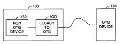
- the peripheral device 130may comprise a non-OTG compliant device 132 and the circuit 100 .
- the non-OTG device 132may be coupled to an OTG compliant device 134 via the circuit 100 .
- the circuit 100may be configured such that the circuit 132 appears to the OTG compliant device 134 as an OTG compliant device.
- the circuit 100may be configured to couple a first legacy device (e.g., a digital still camera) 142 to a second legacy device (e.g., a printer) 144 .
- the circuit 100may be configured to manage communications between the two legacy devices.
- the configuration of the circuit 100may be implemented in software.
- the configuration of the circuit 100may be implemented in firmware or logic (e.g., programmable logic or a state machine).
- the circuit 100may be implemented as part of either the camera or the printer.
- the circuit 100may be implemented as a stand-alone device.
- FIG. 6a block diagram of a circuit 100 ′ illustrating an alternative embodiment of the present invention is shown.
- the circuit 100 ′may be implemented similarly to the circuit 100 except that the circuit 100 ′ may comprise a controller 106 ′ and a number of host/peripheral ports 110 a ′– 110 n ′.
- the controller circuit 106 ′may be configured to relay signals received from any one port (e.g., 110 i ′) to all of the other ports 110 a ′– 110 n′.
- the circuit 100may first enumerate both the legacy device coupled to the port 102 and the USB OTG device coupled to the port 104 (e.g., the block 152 ).
- the circuit 100may be configured to continuously poll the legacy device coupled to the port 102 for data on each of a number of IN endpoints (e.g., the block 154 ).
- the circuit 100may also poll for data on ISO and interrupt IN endpoints with a frequency specified by the descriptors of the device coupled to the port 102 .
- the dataWhen data is received from the device coupled to the port 102 , the data may be transmitted by the circuit 100 to the USB OTG device coupled to the port 104 (e.g., the block 156 ) using an appropriate OUT endpoint (if one has been enumerated).
- the circuit 100may also perform the converse operation.
- the circuit 100may be configured to poll the IN endpoints of the USB OTG device coupled to the port 104 (e.g., the block 154 ) and relay the data to the device coupled to the port 102 via one or more OUT endpoints (e.g., the block 156 ).
- the endpoints of the USB OTG device coupled to the port 104 and the endpoints of the device coupled to the port 102need to match in order for the configuration to function properly.
- a similar configurationmay be necessary for any OTG dual role device (DRD), since OTG devices do not necessarily inter-operate as USB peripherals and PCs typically do.
- DDDOTG dual role device
- the circuit 100may allow a legacy USB device coupled to the port 102 to inter-operate with OTG devices having compatible endpoint sets to the legacy USB device.
- the system 100may be configured to implement firmware that may be mapped differently but with an endpoint set compatible to an endpoint set of the USB OTG device on the port 104 and an endpoint set of the device coupled to the port 102 .
- the circuit 100may first enumerate the legacy USB device coupled to the port 102 (e.g., the block 162 ).
- the circuit 100may be configured to report the descriptors (modified to report OTG capability) received from the device coupled to the port 102 (e.g., the block 166 ).
- the circuit 100may be configured to act as a relay station (e.g., the block 168 ).
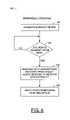
- FIG. 9a flow diagram 170 illustrating yet another example operation of the present invention is shown.
- the circuit 100may respond with a “not acknowledge” (NAK) to the IN token (e.g., the block 174 ).
- NAKnot acknowledge
- the circuit 100may be configured to immediately issue an IN token on the port 102 (or any other port to which the existing (legacy) USB device is connected (e.g., the block 176 ).
- the circuit 100may continue to NAK further IN tokens (on the same endpoint) from the USB OTG device coupled to the port 104 (e.g., the blocks 178 – 182 ).
- the circuit 100may respond to the next IN token from the USB OTG device coupled to the port 104 with the data received from the device on the port 102 (e.g., the blocks 184 and 186 ).
- the circuit 100may be configured to schedule IN requests to the legacy device coupled to the port 102 in anticipation of the IN request from the USB OTG device on the port 104 (e.g., the blocks 188 and 190 ).
- the datamay be ready and waiting for the IN request from the USB OTG device on the port 104 .
- the operationmay be similar, except that the “not acknowledge” stage and associated delay is generally unnecessary.
- the OUT transmissionmay be received and acknowledged, and then relayed to the device coupled to the port 102 by an OUT packet from the device coupled to the port 104 .
- the present inventionmay implement a microcontroller with two USB host/peripheral SIEs.
- An alternative implementation of the inventionmay implement one or both of the SIEs external to the controller 106 .
- the functionality of the controller 106 and associated firmwaremay be implemented using a state machine or other appropriate logic.
- the system 100may be configured to connect a legacy USB camera to a legacy USB printer, allowing the camera to print pictures without a PC being required.
- a configurationmay be implemented either within a USB device such as a printer, or as an after-market accessory.
- the system 100may be configured to take into account the often substantial architectural differences between USB hosts and USB peripherals.
- the system 100may provide an architecture for after-market accessories adding OTG functionality to the installed base of USB peripherals.
- the system 100may provide a bridging function between legacy USB and OTG USB devices.
- the system 100may also provide automatic retransmission by a device having two or more USB host or USB OTG dual role device ports (or a mix thereof) of data received from one port to device(s) connected to the other ports.
- the system 100may bring a fast and low-cost derivative of the USB OTG peripheral to the market.
- the system 100may add OTG functionality to existing USB peripheral designs without the need to re-architect the existing design.
- the system 100may be applicable to USB OTG implementations of future generations of cellular phone handsets.
- FIGS. 7–9may be implemented using a conventional general purpose digital computer programmed according to the teachings of the present specification, as will be apparent to those skilled in the relevant art (s). Appropriate software and/or firmware coding can readily be prepared by skilled programmers based on the teachings of the present disclosure, as will also be apparent to those skilled in the relevant art(s).
- the present inventionmay also be implemented by the preparation of ASICs, FPGAs, PLDS, or by interconnecting an appropriate network of conventional component circuits, as is described herein, modifications of which will be readily apparent to those skilled in the art(s).
- the present inventionthus may also include a computer product which may be a storage medium including instructions which can be used to program a computer to perform a process in accordance with the present invention.
- the storage mediumcan include, but is not limited to, any type of disk including floppy disk, optical disk, CD-ROM, and magneto-optical disks, ROMs, RAMS, EPROMs, EEPROMS, Flash memory, magnetic or optical cards, or any type of media suitable for storing electronic instructions.
Landscapes
- Engineering & Computer Science (AREA)
- Theoretical Computer Science (AREA)
- Physics & Mathematics (AREA)
- General Engineering & Computer Science (AREA)
- General Physics & Mathematics (AREA)
- Information Transfer Systems (AREA)
Abstract
Description
Claims (23)
Priority Applications (1)
| Application Number | Priority Date | Filing Date | Title |
|---|---|---|---|
| US10/073,434US7000057B1 (en) | 2002-02-11 | 2002-02-11 | Method and apparatus for adding OTG dual role device capability to a USB peripheral |
Applications Claiming Priority (1)
| Application Number | Priority Date | Filing Date | Title |
|---|---|---|---|
| US10/073,434US7000057B1 (en) | 2002-02-11 | 2002-02-11 | Method and apparatus for adding OTG dual role device capability to a USB peripheral |
Publications (1)
| Publication Number | Publication Date |
|---|---|
| US7000057B1true US7000057B1 (en) | 2006-02-14 |
Family
ID=35768068
Family Applications (1)
| Application Number | Title | Priority Date | Filing Date |
|---|---|---|---|
| US10/073,434Expired - LifetimeUS7000057B1 (en) | 2002-02-11 | 2002-02-11 | Method and apparatus for adding OTG dual role device capability to a USB peripheral |
Country Status (1)
| Country | Link |
|---|---|
| US (1) | US7000057B1 (en) |
Cited By (25)
| Publication number | Priority date | Publication date | Assignee | Title |
|---|---|---|---|---|
| US20040037310A1 (en)* | 2002-04-26 | 2004-02-26 | Seiko Epson Corporation | Data transfer control device, electronic equipment, and data transfer control method |
| US20040073697A1 (en)* | 2002-06-17 | 2004-04-15 | Seiko Epson Corporation | Data transfer control device, electronic equipment, and data transfer control method |
| US20040243756A1 (en)* | 2003-04-09 | 2004-12-02 | Chanson Lin | USB device for decreasing the current at load |
| US20050091437A1 (en)* | 2003-10-28 | 2005-04-28 | Hung-Chun Yang | Multi-function universal serial bus wireless bridge |
| US20050120343A1 (en)* | 2003-12-01 | 2005-06-02 | Horng-Ming Tai | Method and system for firmware downloads |
| US20050182883A1 (en)* | 2004-02-03 | 2005-08-18 | Overtoom Eric J. | USB OTG intelligent hub/router for debugging USB OTG devices |
| US20050216650A1 (en)* | 2002-06-12 | 2005-09-29 | Jerome Tjia | Bus system, station for use in a bus system, and bus interface |
| US20050251589A1 (en)* | 2004-05-04 | 2005-11-10 | Jung-Chung Wang | Method of authenticating universal serail bus on-the-go device |
| US20060059289A1 (en)* | 2002-09-24 | 2006-03-16 | Koninklijke Phillips Electronics N.C. | Bus connection system |
| US20060065743A1 (en)* | 2004-09-30 | 2006-03-30 | Stmicroelectronics, Inc. | USB device with secondary USB on-the-go function |
| US20060076977A1 (en)* | 2004-09-20 | 2006-04-13 | Xiaoming Zhu | USB 1.1 for USB OTG implementation |
| US20060106962A1 (en)* | 2004-11-17 | 2006-05-18 | Woodbridge Nancy G | USB On-The-Go implementation |
| US20060268940A1 (en)* | 2005-05-31 | 2006-11-30 | Asmedia Technology Inc. | Apparatus for extending a serial port interface |
| US20070038785A1 (en)* | 2005-08-15 | 2007-02-15 | Research In Motion Limited | Universal peripheral connector |
| US20070245059A1 (en)* | 1994-05-28 | 2007-10-18 | Jerome Tjia | Bus Connection Device |
| US20080098139A1 (en)* | 2006-10-24 | 2008-04-24 | Via Technologies, Inc. | High speed data transmission system and method |
| US20080215774A1 (en)* | 2007-01-26 | 2008-09-04 | Hae Jin Kim | Wireless Universal Serial Bus Dual Role Device |
| US20090172384A1 (en)* | 2007-12-31 | 2009-07-02 | Datalogic Mobile, Inc. | Systems and methods for configuring, updating, and booting an alternate operating system on a portable data reader |
| US7606951B2 (en) | 2004-11-12 | 2009-10-20 | Woodbridge Nancy G | Memory reuse for multiple endpoints in USB device |
| US7660938B1 (en)* | 2004-10-01 | 2010-02-09 | Super Talent Electronics, Inc. | Flash card reader and data exchanger utilizing low power extended USB protocol without polling |
| US20100169511A1 (en)* | 2008-12-31 | 2010-07-01 | Dunstan Robert A | Universal serial bus host to host communications |
| US20160277235A1 (en)* | 2015-03-17 | 2016-09-22 | Microsoft Technology Licensing, Llc | Intelligent role selection for dual-role devices |
| US10691838B2 (en)* | 2014-06-20 | 2020-06-23 | Cypress Semiconductor Corporation | Encryption for XIP and MMIO external memories |
| CN112713460A (en)* | 2019-10-24 | 2021-04-27 | 意法半导体(大西部)公司 | USB connector device |
| US20220327087A1 (en)* | 2019-10-18 | 2022-10-13 | Autel Intelligent Technology Corp., Ltd. | Interface circuit, and method and apparatus for interface communication thereof |
Citations (9)
| Publication number | Priority date | Publication date | Assignee | Title |
|---|---|---|---|---|
| US6128732A (en)* | 1997-12-15 | 2000-10-03 | Compaq Computer Corporation | Implementing universal serial bus support with a minimum of system RAM |
| US20030030412A1 (en)* | 2001-08-10 | 2003-02-13 | Seiko Epson Corporation | Power control circuit, electronic instrument, and charging method |
| US20030101311A1 (en)* | 2001-09-28 | 2003-05-29 | Chang Yeow Khai | Bus system and bus interface for connection to a bus |
| US20030101308A1 (en)* | 2001-09-27 | 2003-05-29 | Chang Yeow Khai | Bus system and bus interface for connection to a bus |
| US20030104835A1 (en)* | 2001-11-23 | 2003-06-05 | Alcatel | Mobile terminal comprising connection means |
| US20040008684A1 (en)* | 1999-12-28 | 2004-01-15 | Garney John I. | Transaction scheduling for a bus system in a multiple speed environment |
| US6721332B1 (en)* | 1998-11-10 | 2004-04-13 | Nortel Networks Limited | USB networking on a multiple access transmission medium |
| US6754811B1 (en)* | 2000-06-16 | 2004-06-22 | International Business Machines Corporation | Operating system device centric agent |
| US6816750B1 (en)* | 2000-06-09 | 2004-11-09 | Cirrus Logic, Inc. | System-on-a-chip |
- 2002
- 2002-02-11USUS10/073,434patent/US7000057B1/ennot_activeExpired - Lifetime
Patent Citations (9)
| Publication number | Priority date | Publication date | Assignee | Title |
|---|---|---|---|---|
| US6128732A (en)* | 1997-12-15 | 2000-10-03 | Compaq Computer Corporation | Implementing universal serial bus support with a minimum of system RAM |
| US6721332B1 (en)* | 1998-11-10 | 2004-04-13 | Nortel Networks Limited | USB networking on a multiple access transmission medium |
| US20040008684A1 (en)* | 1999-12-28 | 2004-01-15 | Garney John I. | Transaction scheduling for a bus system in a multiple speed environment |
| US6816750B1 (en)* | 2000-06-09 | 2004-11-09 | Cirrus Logic, Inc. | System-on-a-chip |
| US6754811B1 (en)* | 2000-06-16 | 2004-06-22 | International Business Machines Corporation | Operating system device centric agent |
| US20030030412A1 (en)* | 2001-08-10 | 2003-02-13 | Seiko Epson Corporation | Power control circuit, electronic instrument, and charging method |
| US20030101308A1 (en)* | 2001-09-27 | 2003-05-29 | Chang Yeow Khai | Bus system and bus interface for connection to a bus |
| US20030101311A1 (en)* | 2001-09-28 | 2003-05-29 | Chang Yeow Khai | Bus system and bus interface for connection to a bus |
| US20030104835A1 (en)* | 2001-11-23 | 2003-06-05 | Alcatel | Mobile terminal comprising connection means |
Non-Patent Citations (6)
| Title |
|---|
| "Cypress Introduces Industry's First USB On-The-Go (OTG) Reference Design", Cypress Press Release, Dec. 18, 2001, pp. 1-2. |
| "On-The-Go Supplement to the USB Specification", Revision 1.0, Dec. 18, 2001, pp. 1-66. |
| "SL811HS OTG Application Note", Cypress Semiconductor Corporation, Dec. 17, 2001, pp. 1-4. |
| "Universal Serial Bus Specification", Revision 1.1, Sep. 23, 1998, pp. 1-311. |
| "Universal Serial Bus Specification", Revision 2.0, Apr. 27, 2000, pp. 1-622. |
| "USB On-The-Go Basics", Application Note 1822, Maxim Integrated Products, Dec. 20, 2002, 4 pp. (http://pdfserv.maxim-ic.com/en/an/AN1822.pdf).* |
Cited By (45)
| Publication number | Priority date | Publication date | Assignee | Title |
|---|---|---|---|---|
| US20070245059A1 (en)* | 1994-05-28 | 2007-10-18 | Jerome Tjia | Bus Connection Device |
| US7428600B2 (en)* | 2002-04-26 | 2008-09-23 | Seiko Epson Corporation | Data transfer control device, electronic equipment, and data transfer control method |
| US20040037310A1 (en)* | 2002-04-26 | 2004-02-26 | Seiko Epson Corporation | Data transfer control device, electronic equipment, and data transfer control method |
| US20050216650A1 (en)* | 2002-06-12 | 2005-09-29 | Jerome Tjia | Bus system, station for use in a bus system, and bus interface |
| US7383372B2 (en)* | 2002-06-12 | 2008-06-03 | Nxp B.V. | Bus system, station for use in a bus system, and bus interface |
| US7349973B2 (en)* | 2002-06-17 | 2008-03-25 | Seiko Epson Corporation | Data transfer control device, electronic equipment, and data transfer control method |
| US20040073697A1 (en)* | 2002-06-17 | 2004-04-15 | Seiko Epson Corporation | Data transfer control device, electronic equipment, and data transfer control method |
| US20060059289A1 (en)* | 2002-09-24 | 2006-03-16 | Koninklijke Phillips Electronics N.C. | Bus connection system |
| US7640385B2 (en)* | 2002-09-24 | 2009-12-29 | St-Ericsson Sa | Dual-mode bus station and system for communications |
| US20040243756A1 (en)* | 2003-04-09 | 2004-12-02 | Chanson Lin | USB device for decreasing the current at load |
| US20050091437A1 (en)* | 2003-10-28 | 2005-04-28 | Hung-Chun Yang | Multi-function universal serial bus wireless bridge |
| US7562360B2 (en)* | 2003-12-01 | 2009-07-14 | Texas Instruments Incorporated | Method and system for firmware downloads |
| US20050120343A1 (en)* | 2003-12-01 | 2005-06-02 | Horng-Ming Tai | Method and system for firmware downloads |
| US20050182883A1 (en)* | 2004-02-03 | 2005-08-18 | Overtoom Eric J. | USB OTG intelligent hub/router for debugging USB OTG devices |
| US7152190B2 (en)* | 2004-02-03 | 2006-12-19 | Motorola Inc. | USB OTG intelligent hub/router for debugging USB OTG devices |
| US20070067525A1 (en)* | 2004-04-09 | 2007-03-22 | Chanson Lin | USB device for decreasing the current at load |
| US20050251589A1 (en)* | 2004-05-04 | 2005-11-10 | Jung-Chung Wang | Method of authenticating universal serail bus on-the-go device |
| US7484031B2 (en)* | 2004-05-28 | 2009-01-27 | Nxp B.V. | Bus connection device |
| US20060076977A1 (en)* | 2004-09-20 | 2006-04-13 | Xiaoming Zhu | USB 1.1 for USB OTG implementation |
| US7193442B2 (en)* | 2004-09-20 | 2007-03-20 | Texas Instruments Incorporated | USB 1.1 for USB OTG implementation |
| US7413129B2 (en)* | 2004-09-30 | 2008-08-19 | Stmicroelectronics, Inc. | USB device with secondary USB on-the-go function |
| US20060065743A1 (en)* | 2004-09-30 | 2006-03-30 | Stmicroelectronics, Inc. | USB device with secondary USB on-the-go function |
| US7660938B1 (en)* | 2004-10-01 | 2010-02-09 | Super Talent Electronics, Inc. | Flash card reader and data exchanger utilizing low power extended USB protocol without polling |
| US7606951B2 (en) | 2004-11-12 | 2009-10-20 | Woodbridge Nancy G | Memory reuse for multiple endpoints in USB device |
| USRE45457E1 (en) | 2004-11-12 | 2015-04-07 | Micron Technology, Inc. | Memory reuse for multiple endpoints in USB device |
| US20060106962A1 (en)* | 2004-11-17 | 2006-05-18 | Woodbridge Nancy G | USB On-The-Go implementation |
| US20060268940A1 (en)* | 2005-05-31 | 2006-11-30 | Asmedia Technology Inc. | Apparatus for extending a serial port interface |
| US10049066B2 (en) | 2005-08-15 | 2018-08-14 | Fundamental Innovation Systems International Llc | Universal peripheral connector |
| US20070038785A1 (en)* | 2005-08-15 | 2007-02-15 | Research In Motion Limited | Universal peripheral connector |
| US8024500B2 (en)* | 2005-08-15 | 2011-09-20 | Research In Motion Limited | Universal peripheral connector |
| US8554971B2 (en) | 2005-08-15 | 2013-10-08 | Blackberry Limited | Universal peripheral connector |
| US9098429B2 (en) | 2005-08-15 | 2015-08-04 | Blackberry Limited | Universal peripheral connector |
| US20080098139A1 (en)* | 2006-10-24 | 2008-04-24 | Via Technologies, Inc. | High speed data transmission system and method |
| US20080215774A1 (en)* | 2007-01-26 | 2008-09-04 | Hae Jin Kim | Wireless Universal Serial Bus Dual Role Device |
| US20090172384A1 (en)* | 2007-12-31 | 2009-07-02 | Datalogic Mobile, Inc. | Systems and methods for configuring, updating, and booting an alternate operating system on a portable data reader |
| US9298479B2 (en) | 2007-12-31 | 2016-03-29 | Datalogic ADC, Inc. | Systems and methods for configuring, updating, and booting an alternate operating system on a portable data reader |
| US20100169511A1 (en)* | 2008-12-31 | 2010-07-01 | Dunstan Robert A | Universal serial bus host to host communications |
| US9104821B2 (en)* | 2008-12-31 | 2015-08-11 | Intel Corporation | Universal serial bus host to host communications |
| US10691838B2 (en)* | 2014-06-20 | 2020-06-23 | Cypress Semiconductor Corporation | Encryption for XIP and MMIO external memories |
| US10122576B2 (en)* | 2015-03-17 | 2018-11-06 | Microsoft Technology Licensing, Llc | Intelligent role selection for dual-role devices |
| US20160277235A1 (en)* | 2015-03-17 | 2016-09-22 | Microsoft Technology Licensing, Llc | Intelligent role selection for dual-role devices |
| US20220327087A1 (en)* | 2019-10-18 | 2022-10-13 | Autel Intelligent Technology Corp., Ltd. | Interface circuit, and method and apparatus for interface communication thereof |
| US11989150B2 (en)* | 2019-10-18 | 2024-05-21 | Autel Intelligent Technology Corp., Ltd. | Interface circuit, and method and apparatus for interface communication thereof |
| CN112713460A (en)* | 2019-10-24 | 2021-04-27 | 意法半导体(大西部)公司 | USB connector device |
| US11636060B2 (en)* | 2019-10-24 | 2023-04-25 | STMicroelectronics (Grand Ouest) SAS | USB connector device |
Similar Documents
| Publication | Publication Date | Title |
|---|---|---|
| US7000057B1 (en) | Method and apparatus for adding OTG dual role device capability to a USB peripheral | |
| US6012111A (en) | PC chipset with integrated clock synthesizer | |
| KR100572165B1 (en) | Universal Serial Bus Device Controller | |
| KR100306636B1 (en) | PCI-ISA Interrupt Protocol Converter and Selection Mechanism | |
| US6845420B2 (en) | System for supporting both serial and parallel storage devices on a connector | |
| US6272584B1 (en) | System board with consolidated EEPROM module | |
| US5941965A (en) | Universal docking station | |
| KR101043842B1 (en) | Physical device(phy) support of the usb2.0 link power management addendum using a ulpi phy interface standard | |
| CN101604301B (en) | Use of bond option to alternate between pci configuration space | |
| CA2273719C (en) | High performance pci with backward compatibility | |
| US6502156B1 (en) | Controlling I/O devices independently of a host processor | |
| US5561772A (en) | Expansion bus system for replicating an internal bus as an external bus with logical interrupts replacing physical interrupt lines | |
| CN112988637B (en) | I3C hub to facilitate backward compatibility with I2C | |
| US5655142A (en) | High performance derived local bus and computer system employing the same | |
| JPH08180013A (en) | Computer system,method for reconfiguration of configuration register of pci bus device in response to change in pci bus clock signal frequency and method in which pci bus interfacenotifies operator of operating speed different from pci bus | |
| US7225288B2 (en) | Extended host controller test mode support for use with full-speed USB devices | |
| US5794014A (en) | Method and apparatus for interfacing between peripherals of multiple formats and a single system bus | |
| US6014717A (en) | PCMCIA host adapter and method for variable data transfers | |
| US7469304B2 (en) | Data transfer control device, electronic equipment, and method for a data transfer through a bus, the data transfer control device including a register and a packet buffer that are commonly used during a host operation and a peripheral operation | |
| TW476882B (en) | Computer system | |
| US20010042150A1 (en) | Universal docking station | |
| US7103703B1 (en) | Back to back connection of PCI host bridges on a single PCI bus | |
| Abbott | PCI bus demystified | |
| US7386648B2 (en) | PC card controller with reduced number of terminals | |
| US20060095626A1 (en) | Multifunction adapter |
Legal Events
| Date | Code | Title | Description |
|---|---|---|---|
| AS | Assignment | Owner name:CYPRESS SEMICONDUCTOR CORPORATION, CALIFORNIA Free format text:ASSIGNMENT OF ASSIGNORS INTEREST;ASSIGNORS:NOVELL, PAUL;WRIGHT, DAVID G.;REEL/FRAME:012587/0540;SIGNING DATES FROM 20020207 TO 20020211 | |
| STCF | Information on status: patent grant | Free format text:PATENTED CASE | |
| REMI | Maintenance fee reminder mailed | ||
| FPAY | Fee payment | Year of fee payment:4 | |
| SULP | Surcharge for late payment | ||
| FPAY | Fee payment | Year of fee payment:8 | |
| AS | Assignment | Owner name:MORGAN STANLEY SENIOR FUNDING, INC., NEW YORK Free format text:SECURITY INTEREST;ASSIGNORS:CYPRESS SEMICONDUCTOR CORPORATION;SPANSION LLC;REEL/FRAME:035240/0429 Effective date:20150312 | |
| AS | Assignment | Owner name:SPANSION LLC, CALIFORNIA Free format text:PARTIAL RELEASE OF SECURITY INTEREST IN PATENTS;ASSIGNOR:MORGAN STANLEY SENIOR FUNDING, INC., AS COLLATERAL AGENT;REEL/FRAME:039708/0001 Effective date:20160811 Owner name:CYPRESS SEMICONDUCTOR CORPORATION, CALIFORNIA Free format text:PARTIAL RELEASE OF SECURITY INTEREST IN PATENTS;ASSIGNOR:MORGAN STANLEY SENIOR FUNDING, INC., AS COLLATERAL AGENT;REEL/FRAME:039708/0001 Effective date:20160811 | |
| FEPP | Fee payment procedure | Free format text:PAYOR NUMBER ASSIGNED (ORIGINAL EVENT CODE: ASPN); ENTITY STATUS OF PATENT OWNER: LARGE ENTITY | |
| AS | Assignment | Owner name:MONTEREY RESEARCH, LLC, CALIFORNIA Free format text:ASSIGNMENT OF ASSIGNORS INTEREST;ASSIGNOR:CYPRESS SEMICONDUCTOR CORPORATION;REEL/FRAME:040911/0238 Effective date:20160811 | |
| FEPP | Fee payment procedure | Free format text:MAINTENANCE FEE REMINDER MAILED (ORIGINAL EVENT CODE: REM.) | |
| FEPP | Fee payment procedure | Free format text:11.5 YR SURCHARGE- LATE PMT W/IN 6 MO, LARGE ENTITY (ORIGINAL EVENT CODE: M1556) | |
| MAFP | Maintenance fee payment | Free format text:PAYMENT OF MAINTENANCE FEE, 12TH YEAR, LARGE ENTITY (ORIGINAL EVENT CODE: M1553) Year of fee payment:12 | |
| AS | Assignment | Owner name:MORGAN STANLEY SENIOR FUNDING, INC., NEW YORK Free format text:CORRECTIVE ASSIGNMENT TO CORRECT THE 8647899 PREVIOUSLY RECORDED ON REEL 035240 FRAME 0429. ASSIGNOR(S) HEREBY CONFIRMS THE SECURITY INTERST;ASSIGNORS:CYPRESS SEMICONDUCTOR CORPORATION;SPANSION LLC;REEL/FRAME:058002/0470 Effective date:20150312 |