US6998871B2 - Configurable integrated circuit for use in a multi-function handheld device - Google Patents
Configurable integrated circuit for use in a multi-function handheld deviceDownload PDFInfo
- Publication number
- US6998871B2 US6998871B2US10/723,634US72363403AUS6998871B2US 6998871 B2US6998871 B2US 6998871B2US 72363403 AUS72363403 AUS 72363403AUS 6998871 B2US6998871 B2US 6998871B2
- Authority
- US
- United States
- Prior art keywords
- input
- operably coupled
- data
- gpio
- output
- Prior art date
- Legal status (The legal status is an assumption and is not a legal conclusion. Google has not performed a legal analysis and makes no representation as to the accuracy of the status listed.)
- Expired - Lifetime, expires
Links
Images


Classifications
- G—PHYSICS
- G06—COMPUTING OR CALCULATING; COUNTING
- G06F—ELECTRIC DIGITAL DATA PROCESSING
- G06F1/00—Details not covered by groups G06F3/00 - G06F13/00 and G06F21/00
- G06F1/16—Constructional details or arrangements
- G06F1/1613—Constructional details or arrangements for portable computers
- G—PHYSICS
- G06—COMPUTING OR CALCULATING; COUNTING
- G06F—ELECTRIC DIGITAL DATA PROCESSING
- G06F3/00—Input arrangements for transferring data to be processed into a form capable of being handled by the computer; Output arrangements for transferring data from processing unit to output unit, e.g. interface arrangements
- G06F3/16—Sound input; Sound output
- G—PHYSICS
- G11—INFORMATION STORAGE
- G11C—STATIC STORES
- G11C7/00—Arrangements for writing information into, or reading information out from, a digital store
- G11C7/16—Storage of analogue signals in digital stores using an arrangement comprising analogue/digital [A/D] converters, digital memories and digital/analogue [D/A] converters
- G—PHYSICS
- G11—INFORMATION STORAGE
- G11B—INFORMATION STORAGE BASED ON RELATIVE MOVEMENT BETWEEN RECORD CARRIER AND TRANSDUCER
- G11B20/00—Signal processing not specific to the method of recording or reproducing; Circuits therefor
- G11B20/10—Digital recording or reproducing
- G11B20/10527—Audio or video recording; Data buffering arrangements
- G—PHYSICS
- G11—INFORMATION STORAGE
- G11C—STATIC STORES
- G11C2207/00—Indexing scheme relating to arrangements for writing information into, or reading information out from, a digital store
- G11C2207/16—Solid state audio
Definitions
- This inventionrelates generally to portable electronic equipment and more particularly to integrated circuits used within such portable electronic equipment.
- Integrated circuitsare used in a wide variety of electronic equipment, including portable, or handheld, devices.
- Such handheld devicesinclude personal digital assistants (PDA), CD players, MP3 players, DVD players, AM/FM radio, a pager, cellular telephones, computer memory extension (commonly referred to as a thumb drive or USB flash disk), etc.
- PDApersonal digital assistants
- CD playersCD players
- MP3 playersdigital versatile players
- DVD playersdigital versatile disc drives
- AM/FM radioa pager
- cellular telephonescommonly referred to as a thumb drive or USB flash disk
- a thumb drivemay include an integrated circuit for interfacing with a computer (e.g., personal computer, laptop, server, workstation, etc.) via one of the ports of the computer (e.g., Universal Serial Bus (USB), parallel port, FireWire, etc.) and at least one other memory integrated circuit (e.g., flash memory).
- USBUniversal Serial Bus
- thumb drivewhen the thumb drive is coupled to a computer, data can be read from and written to the memory of the thumb drive. Accordingly, a user may store personalized information (e.g., presentations, Internet access account information, etc.) on his/her thumb drive and use any computer to access the information.
- personalized informatione.g., presentations, Internet access account information, etc.
- an MP3 playermay include multiple integrated circuits to support the storage and playback of digitally formatted audio (e.g., formatted in accordance with the MP3 specification).
- one integrated circuitmay be used for interfacing with a computer, another integrated circuit for generating a power supply voltage, another for processing the storage and/or playback of the digitally formatted audio data, and still another for rendering the playback of the digitally formatted audio data audible.
- integrated circuitshave enabled the creation of a plethora of handheld devices, however, to be “wired” in today's electronic world, a person needs to posses multiple handheld devices.
- a personmay own a cellular telephone for cellular telephone service, a PDA for scheduling, address book, etc., one or more thumb drives for extended memory functionality, an MP3 player for storage and/or playback of digitally recorded music, a radio, etc.
- a single handheld devicemay be relatively small, carrying multiple handheld devices on one's person can become quite burdensome.
- each manufacturer of such handheld devicestypically offers different look and feel (e.g., features, functions, input/output configurations, etc.) of its handheld devices to distinguish itself in the market place.
- a manufacturermay offer several versions of a handheld device with varying feature sets to appeal to multiple market groups. Accordingly, such manufacturers require a multitude of integrated circuits to accommodate their various handheld products. For an integrated circuit manufacturer's perspective, they are required to develop multiple integrated circuits for each of their handheld manufacturing clients or, at a minimum, develop client specific integrated circuits for each handheld manufacturing client that includes multiple features that may or may not be used. As is well known in the integrated circuit field, having to develop multiple versions of essentially the same integrated circuit is costly and substantially impacts profit margins. As is further known, including multiple features on an integrated circuit increases the integrated circuit's pin count, which further adds to the cost of the integrated circuit.
- a configurable integrated circuitfor use in a multiple function handheld device of the present invention substantially meets these needs and others.
- a configurable integrated circuitincludes at least one general purpose input/output (GPIO) interface module, a first functional module, and a second functional module.
- the GPIO interface moduleincludes a plurality of GPIO cells, wherein each of the GPIO cells is operably coupled to a corresponding pin of the configurable integrated circuit.
- GPIOgeneral purpose input/output
- the configurable integrated circuitWhen the configurable integrated circuit is in a second functional mode, at least one of the GPIO cells is operably coupled to its corresponding pin such that the corresponding pin functions as a digital output pin for the second functional module.
- the corresponding pinfunctions as a digital output pin for the second functional module.
- FIG. 1is a schematic block diagram of a multi-function handheld device in accordance with the present invention.
- FIG. 2is a schematic block diagram of another multi-function handheld device in accordance with the present invention.
- FIG. 3is a schematic block diagram of a configurable integrated circuit in accordance with the present invention.
- FIG. 4is a schematic block diagram of a general purpose input/output interface module in accordance with the present invention.
- FIG. 5is a schematic block diagram of another general purpose input/output interface module in accordance with the present invention.
- FIG. 6is a schematic block diagram of a general purpose input/output cell in accordance with the present invention.
- FIG. 7is a schematic block diagram of another configurable integrated circuit in accordance with the present invention.
- FIG. 8is a schematic block diagram of yet another configurable integrated circuit in accordance with the present invention.
- FIG. 1is a schematic block diagram of a multi-function handheld device 10 and corresponding integrated circuit 12 operably coupled to a host device A, B, or C.
- the multi-function handheld device 10also includes memory integrated circuit (IC) 16 and a battery 14 .
- the integrated circuit 12includes a host interface 18 , a processing module 20 , a memory interface 22 , a multimedia module 24 , a DC-to-DC converter 26 , and a bus 28 .
- the multimedia module 24alone or in combination with the processing module 20 provides the functional circuitry for the integrated circuit 12 .
- the DC-to-DC converter 26which may be constructed in accordance with the teaching of U.S. Pat. No.
- the processing module 20When the multi-function handheld device 10 is operably coupled to a host device A, B, or C, which may be a personal computer, workstation, server (which are represented by host device A), a laptop computer (host device B), a personal digital assistant (host device C), and/or any other device that may transceive data with the multifunction handheld device, the processing module 20 performs at least one algorithm 30 , where the corresponding operational instructions of the algorithm 30 are stored in memory 16 and/or in memory incorporated in the processing module 20 .
- the processing module 20may be a single processing device or a plurality of processing devices.
- Such a processing devicemay be a microprocessor, micro-controller, digital signal processor, microcomputer, central processing unit, field programmable gate array, programmable logic device, state machine, logic circuitry, analog circuitry, digital circuitry, and/or any device that manipulates signals (analog and/or digital) based on operational instructions.
- the associated memorymay be a single memory device or a plurality of memory devices.
- Such a memory devicemay be a read-only memory, random access memory, volatile memory, non-volatile memory, static memory, dynamic memory, flash memory, and/or any device that stores digital information.
- the processing module 20implements one or more of its functions via a state machine, analog circuitry, digital circuitry, and/or logic circuitry
- the associated memory storing the corresponding operational instructionsis embedded with the circuitry comprising the state machine, analog circuitry, digital circuitry, and/or logic circuitry.
- the integrated circuit 12facilitates the transfer of data between the host device A, B, or C and memory 16 , which may be non-volatile memory (e.g., flash memory, disk memory, SDRAM) and/or volatile memory (e.g., DRAM).
- the memory IC 16is a NAND flash memory that stores both data and the operational instructions of at least some of the algorithms 30 .
- the processing module 30retrieves a first set of operational instructions (e.g., a file system algorithm, which is known in the art) from the memory 16 to coordinate the transfer of data.
- a first set of operational instructionse.g., a file system algorithm, which is known in the art
- data received from the host device A, B, or Ce.g., Rx data
- the host interface module 18e.g., Rx data
- the received datawill be formatted in a particular manner. For example, if the handheld device 10 is coupled to the host device via a USB cable, the received data will be in accordance with the format proscribed by the USB specification.
- the host interface module 18converts the format of the received data (e.g., USB format) into a desired format by removing overhead data that corresponds to the format of the received data and storing the remaining data as data words.
- the size of the data wordsgenerally corresponds directly to, or a multiple of, the bus width of bus 28 and the word line size (i.e., the size of data stored in a line of memory) of memory 16 .
- the data wordsare provided, via the memory interface 22 , to memory 16 for storage.
- the handheld device 10is functioning as extended memory of the host device (e.g., like a thumb drive).
- the host devicemay retrieve data (e.g., Tx data) from memory 16 as if the memory were part of the computer. Accordingly, the host device provides a read command to the handheld device, which is received via the host interface 18 .
- the host interface 18converts the read request into a generic format and provides the request to the processing module 20 .
- the processing module 20interprets the read request and coordinates the retrieval of the requested data from memory 16 via the memory interface 22 .
- the retrieved data(e.g., Tx data) is provided to the host interface 18 , which converts the format of the retrieved data from the generic format of the handheld device into the format of the coupling between the handheld device and the host device.
- the host interface 18then provides the formatted data to the host device via the coupling.
- the coupling between the host device and the handheld devicemay be a wireless connection or a wired connection.
- a wireless connectionmay be in accordance with Bluetooth, IEEE 802.11(a), (b) or (g), and/or any other wireless LAN (local area network) protocol, IrDA, etc.
- the wired connectionmay be in accordance with one or more Ethernet protocols, FireWire, USB, etc.
- the host interface module 18includes a corresponding encoder and decoder. For example, when the handheld device 10 is coupled to the host device via a USB cable, the host interface module 18 includes a USB encoder and a USB decoder.
- the data stored in memory 16may be text files, presentation files, user profile information for access to varies computer services (e.g., Internet access, email, etc.), digital audio files (e.g., MP3 files, WMA—Windows Media Architecture-, MP3 PRO, Ogg Vorbis, AAC—Advanced Audio Coding, MIDI—Musical Interface), digital video files [e.g., still images or motion video such as MPEG (motion picture expert group) files, JPEG (joint photographic expert group) files, etc.], address book information, and/or any other type of information that may be stored in a digital format.
- the handheld device 10when the handheld device 10 is coupled to the host device A, B, or C, the host device may power the handheld device 10 such that the battery is unused.
- the processing module 20executes an algorithm 30 to detect the disconnection and to place the handheld device in a second functional mode.
- the processing module 20retrieves, and subsequently executes, a second set of operational instructions from memory 16 to support the second functional mode.
- the second functional modemay correspond to MP3 file playback, digital dictaphone recording, MPEG file playback, JPEG file playback, text messaging display, cellular telephone functionality, and/or AM/FM radio reception.
- the second functional modemay correspond to MP3 file playback, digital dictaphone recording, MPEG file playback, JPEG file playback, text messaging display, cellular telephone functionality, and/or AM/FM radio reception.
- the multimedia module 24retrieves multimedia data 34 from memory 16 .
- the multimedia data 34includes at least one of digitized audio data, digital video data, and text data.
- the multimedia module 24converts the data 34 into rendered output data 36 .
- the multimedia module 24may convert digitized data into analog signals that are subsequently rendered audible via a speaker or via a headphone jack.
- the multimedia module 24may render digital video data and/or digital text data into RGB (red-green-blue), YUV, etc., data for display on an LCD (liquid crystal display) monitor, projection CRT, and/or on a plasma type display.
- the multimedia module 24will be described in greater detail with reference to FIG. 2 .
- the handheld device 10may be packaged similarly to a thumb drive, a cellular telephone, pager (e.g., text messaging), a PDA, an MP3 player, a radio, and/or a digital dictaphone and offer the corresponding functions of multiple ones of the handheld devices (e.g., provide a combination of a thumb drive and MP3 player/recorder, a combination of a thumb drive, MP3 player/recorder, and a radio, a combination of a thumb drive, MP3 player/recorder, and a digital dictaphone, combination of a thumb drive, MP3 player/recorder, radio, digital dictaphone, and cellular telephone, etc.).
- FIG. 2is a schematic block diagram of another handheld device 40 and a configurable integrated circuit 12 .
- the handheld device 40includes the configurable integrated circuit 12 , the battery 14 , the memory 16 , a crystal clock source 42 , one or more multimedia input devices (e.g., one or more video capture device(s) 44 , keypad(s) 54 , microphone(s) 46 , etc.), and one or more multimedia output devices (e.g., one or more video and/or text display(s) 48 , speaker(s) 50 , headphone jack(s) 52 , etc.).
- multimedia input devicese.g., one or more video capture device(s) 44 , keypad(s) 54 , microphone(s) 46 , etc.
- multimedia output devicese.g., one or more video and/or text display(s) 48 , speaker(s) 50 , headphone jack(s) 52 , etc.
- the configurable integrated circuit 12includes the host interface 18 , the processing module 20 , the memory interface 22 , the multimedia module 24 , the DC-to-DC converter 26 , random access memory (RAM) 33 , read only memory (ROM) 35 , at least one general purpose input/output (GPIO) interface module 80 , and a clock generator 56 , which produces a clock signal (CLK) for use by the other modules.
- CLKclock signal
- the clock signal CLKmay include multiple synchronized clock signals at varying rates for the various operations of the multifunction handheld device.
- Handheld device 40functions in a similar manner as handheld device 10 when exchanging data with the host device (i.e., when the handheld device is in the first functional mode).
- the handheld device 40may store digital information received via one of the multimedia input devices (e.g., video capture device 44 , microphone 46 , and keypad 54 ).
- a voice recording received via the microphone 46may be provided as multimedia input data 58 , digitized via the multimedia module 24 and digitally stored in memory 16 .
- video recordingsmay be captured via the video capture device 44 (e.g., a digital camera, a camcorder, VCR output, DVD output, etc.) and processed by the multimedia module 24 for storage as digital video data in memory 16 .
- the key pad 54(which may be a keyboard, touch screen interface, or other mechanism for inputting text information) provides text data to the multimedia module 24 for storage as digital text data in memory 16 .
- the processing module 20arbitrates write access to the memory 16 among the various input sources (e.g., the host and the multimedia module).
- the handheld device 40When the handheld device 40 is in the second functional mode (i.e., not connected to the host), the handheld device may record multimedia data to and/or playback multimedia data from the memory 16 .
- the data provided by the host when the handheld device 40 was in the first functional modeincludes the multimedia data.
- the playback of the multimedia datais similar to the playback described with reference to the handheld device 10 of FIG. 1 .
- the rendered output data 36may be provided to one or more of the multimedia output devices.
- rendered audio datamay be provided to the headphone jack 52 and/or to the speaker 50
- rendered video and/or text datamay be provided to the display 48 .
- the handheld device 40may also record multimedia data 34 while in the second functional mode.
- the handheld device 40may store digital information received via one of the multimedia input devices 44 , 46 , and 54 .
- the GPIO interface module 80which will be described in greater detail with reference to FIGS. 4–6 , is operably coupled to bus 28 and to one or more peripheral components of the multi-function handheld device 40 .
- the peripheral componentsinclude, but are not limited to, a CDROM drive, control buttons, switches, light emitting diode (LED) display, liquid crystal display (LCD) display, MMC/SC card, flash memory module, a RAM memory module, a two-wire interface module, hard drive, and a system packet interface module.
- the GPIO interface module 80may be configured to provide an input and/or an output for one or more of the peripheral components of the multi-function handheld device 40 to functional modules of the integrated circuit 12 .
- the functional modulesinclude the processing module 20 , while executing one or more of algorithms 30 , one or more of the functions of the multimedia module 24 , and/or one or more functions of the host.
- the multi-function handheld devicemay be reading data from a CD for recording to memory 16 or for playback via the multimedia module 24 .
- the GPIO interface module 80is configured, with respect to its connection to the CDROM drive, to receive digital data, i.e., the corresponding pins are configured as input pins.
- the multi-function handheld devicemay provide control information (e.g., stop, pause, fast forward, etc.) to the CDROM drive using the same corresponding pins.
- control informatione.g., stop, pause, fast forward, etc.
- the GPIO moduleis reconfigured, with respect to its connection to the CDROM drive, to output digital data i.e., the corresponding pins are configured as output pins.
- pins of the integrated circuit 12 coupled to the GPIO interface module 80may be shared between multiple peripheral devices and/or between multiple functional modules of the integrated circuit 12 .
- the same pins of the integrated circuit 12may be used to output digital data to a display (e.g., LCD or LED) in one mode and, in another mode, be used to receive digital data from buttons and/or switches.
- a displaye.g., LCD or LED
- the pins of the integrated circuitmay be shared via the GPIO interface module 80 to support a multitude of functions provided by the multi-function handheld device.
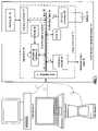
- FIG. 3is a schematic block diagram of another embodiment of the integrated circuit 12 that may be incorporated in the multi-function handheld device 10 .
- the integrated circuit 12includes the GPIO interface module 80 , a CD control interface 82 , a serial packet interface (SPI) module 83 , a two-wire interface module 84 , an LCD display interface module 86 , a static and/or dynamic RAM interface 88 , an LED interface module 90 , processing module 20 , ROM 35 , RAM 33 , a peripheral bus 104 , a memory bus 106 , a system-on-a-chip (SOC) management module 100 , a universal serial bus (USB) interface 102 , a digital-to-analog converter 72 , an analog-to-digital converter 68 , a multiplexer, buffers, mixing module 78 , DC to DC converter 26 , a programmable driver 92 , and a microphone bias module 96 .
- SPIserial packet interface
- the integrated circuit 12may facilitate the transceiving of data with a host device between system memory of a multi-function handheld device and a host device, may playback multimedia data, and/or may record multimedia data via input ports.
- the USB interface 102operably couples the integrated circuit 12 to a host device.
- the RAM interface 88couples, either via the general purpose input/output interface module 80 or directly, to the system memory (e.g., memory IC 16 ) of the multi-function handheld device 10 . In this configuration, data that is received from the host device is placed on the memory bus 106 by the USB interface 102 .
- the SDRAM interface 88retrieves the data from the memory bus 106 and forwards it for storage to the system memory under the control of the processing module 20 that is executing a file system storage algorithm.
- the data being storedmay correspond to playback data, such as an MP3 file, a WMA file, a video file, a text file, and/or a combination thereof.
- the data being received from the hostmay correspond to programming instructions of an algorithm 30 , which may be an MP3 decoder algorithm, a WMA decoder algorithm, a MPEG algorithm, a JPEG algorithm, et cetera.
- the RAM interface 88retrieves data from the system memory and places it on the memory bus 106 under the control of the processing module 20 as it executes a file system algorithm.
- the USB interface 102retrieves the data from the memory bus 106 and forwards it to the host device in accordance with one of the versions of the USB standard.
- Datamay also be stored in the system memory that is received via the CD (compact disk) control interface 82 , and/or via the two-wire interface 84 , which may be expanded to a three or four wire interface. Via these interfaces 82 and 84 , data is received via the general purpose input/output module 80 , which will be described in greater detail with reference to FIGS. 4–8 , and placed on the memory bus 106 .
- the RAM interface 88retrieves the data from the memory bus 106 and provides it to the system memory, which is done under the control of the processing module as it executes a data storage algorithm.
- the microphone bias circuit 96biases the audio input signals for optimal operations and provides them to the mixing module 78 and to the multiplexer (mux) via a buffer.
- the received audio input signalsare converted to digital audio signals via the analog-to-digital converter 68 .
- the digital audio signalsmay then be stored in system memory (e.g., memory IC 16 ).
- the audio input signalmay be provided to the summing module 78 and subsequently provided to headphone jack 94 via the programmable driver 92 as a component of a summed analog signal.
- the summing module 78may sum one or more of the analog input signals it receives from a line input, an FM radio input, the microphone bias circuit 96 , and the analog output of the DAC 72 to produce the summed analog signal.
- digital multimedia datais retrieved from the system memory and provided to the digital-to-analog converter 72 .
- the digital-to-analog converter 72converts the digital multimedia signals, which may be audio data, video data and/or text data, into analog multimedia signals and provides the analog multimedia signals to mixing module 78 .
- the mixing module 78will generally have the other inputs muted, such that its output corresponds directly to the analog multimedia signals provided by the digital-to-analog converter 72 .
- the programmable driver 92increases the drive power of the analog multimedia signals (e.g., audio signals when the analog multimedia signals are provided to a headphone) and provides it to the headphone jack 94 .
- the analog multimedia signalse.g., audio signals when the analog multimedia signals are provided to a headphone
- a fixed drivermay replace the programmable driver 92 to drive the headphone jack 94 .
- the integrated circuit 12may provide video outputs via the LCD interface 86 .
- the display interface 86drives an LCD display, which, alternatively, may be an LED display, plasma display and/or any other type of display.
- the data being displayedmay correspond to the multimedia data retrieved from the system memory, and/or may correspond to the commands inputted via the GPIO interface module 80 .
- the system-on-a-chip (SOC) management module 100processes interrupt controls, generates clock signals for the integrated circuit 12 , performs bit manipulations, performs debugging operations, and executes a Reed-Solomon, or other type of encoding/decoding algorithm to encode and/or decode data.
- SOCsystem-on-a-chip
- the DC to DC converter 26provides at least one supply voltage for the integrated circuit 12 - 3 and typically provides two supply voltages.
- the DC to DC converter 26may produce a 3.3 volts supply and a 1.8 volt supply.
- FIG. 4is a schematic block diagram of an embodiment of the GPIO interface module 80 that includes a plurality of GPIO cells 110 – 118 , which will be described in greater detail with reference to FIG. 6 .
- Each of the GPIO cells 110 – 118is coupled to provide digital output signals from a first functional module 120 to its corresponding IC pin and to receive digital input signals from its corresponding pin and provide them to the second functional module 122 .
- one GPIO cellmay be functioning to receive digital input signals for the second functional module 122
- another GPIO cellmay be functioning to provide digital output signals from the first functional module 120 to its corresponding pin.
- the configuration of whether a GPIO cell will function as an input or an outputis controlled by the processing module 20 as it executes one of it plurality of algorithms 30 .
- the first functional moduleis shown to provide digital output signals it may also include connections to receive digital input signals from the GPIO 80 and the second functional module may also include connections to provide digital output signals to the GPIO 80 .
- the first and second modules 120 and 122may be algorithms being executed by the processing module 20 , operations performed by the multimedia module 24 , and/or any of the interfaces 82 – 90 of FIG. 3 .
- FIG. 5is a schematic block diagram of another embodiment of the GPIO interface module 80 that includes programmable logic fabric 124 and the plurality of GPIO cells 110 – 118 , which will be described in greater detail with reference to FIG. 6 .
- Each of the GPIO cells 110 – 118is coupled to its corresponding IC pin and to receive digital output signals from the programmable logic fabric and to provide them to its corresponding pin and to provide digital input signals from its corresponding pin to the programmable logic fabric 124 .
- the programmable logic fabric 124which may be a field programmable gate array (FPGA), programmable logic device, and/or any other programmable logic circuitry, is coupled to the first and second functional modules 120 and 122 .
- FPGAfield programmable gate array
- the programmable logic fabric 124may be programmed to provide different coupling between the IC pins and the first and second functional modules 120 and 122 to enable a handheld device manufacturer to selectively configure the pin of the integrated circuit 12 to facilitate printed circuit board layout.
- the programmable logic fabric 124may be programmed to process the digital input and output signals prior to providing them to the first and/or second functional modules and/or prior to providing them the corresponding pins.
- Such processingincludes, but is not limited to, encoding the signals in accordance with an encoding protocol (e.g., non-return to zero, multi-level digital encoding, etc.), decoding the signals in accordance with the encoding protocol, encrypting the signals in accordance with an encryption protocol, decrypting the signals in accordance with the encryption protocol, adjusting transmit power levels, amplifying power levels of received signals, forward error correction, and equalization.
- an encoding protocole.g., non-return to zero, multi-level digital encoding, etc.
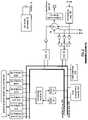
- FIG. 6is a schematic block diagram of a GPIO cell 110 – 118 that is coupled to one pin of the integrated circuit 12 .
- Each of the GPIO cells 110 – 118includes a plurality of registers 130 – 136 , a plurality of multiplexers 138 and 140 , and a plurality of drivers 142 and 144 .
- Register 132stores a mode select signal that controls the multiplexers 138 and 140 .
- register 132In a 1st state of the GPIO cell, which may correspond to configuring the pin as an output pin, register 132 stores a digital value that causes the multiplexer 138 to pass output data from the first or second functional module 120 or 122 to driver 144 .
- register 132provides the digital value corresponding to the first state of the GPIO cell to multiplexer 140 , which causes it to pass an output enable signal, which is produced by the processing module 20 while executing one of its algorithms, to the driver 144 .
- the output enable signaleither activates or deactivates the driver 144 .
- register 132may store an alternative digital value that causes multiplexer 138 to pass data stored in register 134 to driver 144 .
- the data stored in register 134may be provided by the processing module 20 while executing the current algorithm or another algorithm.
- register 132provides the alternative digital value to multiplexer 140 , which passes the output enable signal to driver 144 .
- register 132In a 3 rd state of the GPIO cell, register 132 provides a third digital value to multiplexer 140 , which causes it to pass the data stored in register 136 to control the activation or deactivation of the driver 144 .
- the data stored in register 136may be provided by the processing module 20 which executing one of its algorithms.
- register 132provides the third digital value to multiplexer 138 , which causes it to pass the output data from the first or second functional module to driver 144 .
- register 132may store a fourth digital value that causes multiplexer 138 to pass data stored in register 134 to driver 144 .
- the data stored in register 134may be provided by the processing module 20 while executing the current algorithm or another algorithm.
- register 132provides the fourth digital value to multiplexer 140 , which causes it to pass the data stored in register 136 to control the activation or deactivation of the driver 144 .
- the same pinmay be used for outputting multiple signals from different functional modules, thus reducing the number of pins needed for the integrated circuit.
- the GPIO cellmay be configured to receive digital input signals from its corresponding pin via buffer 142 and to provide the received digital input signals to register 130 and/or to the first or second functional module 120 or 122 (e.g., data in).
- the processing module 20while it executes an algorithm, controls whether the received digital input signals will be provided to register 130 and/or to the first or second functional modules 120 or 122 .
- the processing module 20deactivates the driver 144 .
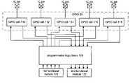
- FIG. 7is a schematic block diagram of another embodiment of integrated circuit 12 , where the integrated circuit 12 includes a plurality of general purpose input/output (GPIO) modules 80 - 1 and 80 - 2 .
- Each GPIO module 80 - 1 and 80 - 2is coupled to the first and second functional modules 120 and 122 , respectively.
- the functional modules 120 and 122may correspond to the processing module 20 , the CD control interface module 82 , the I 2 C interface module 84 , display interface module 86 , RAM interface module 88 , the interface module 90 , and/or any other type of data interface that may be used in a handheld multi-function device.
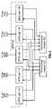
- FIG. 8is a schematic block diagram of an alternate embodiment of an integrated circuit 12 that includes a plurality of GPIOs 80 - 1 and 80 - 2 , a plurality of functional modules 120 and 122 , and programmable logic fabric 124 .
- the programmable logic fabricmay be field programmable gate array circuitry, programmable gate array circuitry and/or any other type of configurable circuitry.
- the integrated circuit 12may include more or less GPIO modules, more or less functional modules 120 and 122 , and more or less programmable logic fabric 124 than shown in FIG. 8 .
- the term “substantially” or “approximately”, as may be used herein,provides an industry-accepted tolerance to its corresponding term. Such an industry-accepted tolerance ranges from less than one percent to twenty percent and corresponds to, but is not limited to, component values, integrated circuit process variations, temperature variations, rise and fall times, and/or thermal noise.
- the term “operably coupled”, as may be used herein,includes direct coupling and indirect coupling via another component, element, circuit, or module where, for indirect coupling, the intervening component, element, circuit, or module does not modify the information of a signal but may adjust its current level, voltage level, and/or power level.
- inferred couplingincludes direct and indirect coupling between two elements in the same manner as “operably coupled”.
- the term “compares favorably”, as may be used herein,indicates that a comparison between two or more elements, items, signals, etc., provides a desired relationship. For example, when the desired relationship is that signal 1 has a greater magnitude than signal 2 , a favorable comparison may be achieved when the magnitude of signal 1 is greater than that of signal 2 or when the magnitude of signal 2 is less than that of signal 1 .
Landscapes
- Engineering & Computer Science (AREA)
- Theoretical Computer Science (AREA)
- Physics & Mathematics (AREA)
- Human Computer Interaction (AREA)
- General Engineering & Computer Science (AREA)
- General Physics & Mathematics (AREA)
- Computer Hardware Design (AREA)
- Health & Medical Sciences (AREA)
- Audiology, Speech & Language Pathology (AREA)
- General Health & Medical Sciences (AREA)
- Semiconductor Integrated Circuits (AREA)
- Telephone Function (AREA)
- Microcomputers (AREA)
- Power Sources (AREA)
- Stored Programmes (AREA)
Abstract
Description
Claims (21)
Priority Applications (4)
| Application Number | Priority Date | Filing Date | Title |
|---|---|---|---|
| US10/723,634US6998871B2 (en) | 2002-11-29 | 2003-11-26 | Configurable integrated circuit for use in a multi-function handheld device |
| US11/189,308US7109745B2 (en) | 2002-11-29 | 2005-07-26 | Configurable integrated circuit for use in a multi-function handheld device |
| US11/407,475US7129743B2 (en) | 2002-11-29 | 2006-04-20 | Digital audio system on a chip |
| US11/526,839US7250787B2 (en) | 2002-11-29 | 2006-09-25 | Digital audio system on a chip with configurable GPIOs |
Applications Claiming Priority (2)
| Application Number | Priority Date | Filing Date | Title |
|---|---|---|---|
| US42994102P | 2002-11-29 | 2002-11-29 | |
| US10/723,634US6998871B2 (en) | 2002-11-29 | 2003-11-26 | Configurable integrated circuit for use in a multi-function handheld device |
Related Child Applications (3)
| Application Number | Title | Priority Date | Filing Date |
|---|---|---|---|
| US11/189,308ContinuationUS7109745B2 (en) | 2002-11-29 | 2005-07-26 | Configurable integrated circuit for use in a multi-function handheld device |
| US11/407,475ContinuationUS7129743B2 (en) | 2002-11-29 | 2006-04-20 | Digital audio system on a chip |
| US11/526,839ContinuationUS7250787B2 (en) | 2002-11-29 | 2006-09-25 | Digital audio system on a chip with configurable GPIOs |
Publications (2)
| Publication Number | Publication Date |
|---|---|
| US20040107303A1 US20040107303A1 (en) | 2004-06-03 |
| US6998871B2true US6998871B2 (en) | 2006-02-14 |
Family
ID=32397230
Family Applications (4)
| Application Number | Title | Priority Date | Filing Date |
|---|---|---|---|
| US10/723,634Expired - LifetimeUS6998871B2 (en) | 2002-11-29 | 2003-11-26 | Configurable integrated circuit for use in a multi-function handheld device |
| US11/189,308Expired - LifetimeUS7109745B2 (en) | 2002-11-29 | 2005-07-26 | Configurable integrated circuit for use in a multi-function handheld device |
| US11/407,475Expired - LifetimeUS7129743B2 (en) | 2002-11-29 | 2006-04-20 | Digital audio system on a chip |
| US11/526,839Expired - LifetimeUS7250787B2 (en) | 2002-11-29 | 2006-09-25 | Digital audio system on a chip with configurable GPIOs |
Family Applications After (3)
| Application Number | Title | Priority Date | Filing Date |
|---|---|---|---|
| US11/189,308Expired - LifetimeUS7109745B2 (en) | 2002-11-29 | 2005-07-26 | Configurable integrated circuit for use in a multi-function handheld device |
| US11/407,475Expired - LifetimeUS7129743B2 (en) | 2002-11-29 | 2006-04-20 | Digital audio system on a chip |
| US11/526,839Expired - LifetimeUS7250787B2 (en) | 2002-11-29 | 2006-09-25 | Digital audio system on a chip with configurable GPIOs |
Country Status (1)
| Country | Link |
|---|---|
| US (4) | US6998871B2 (en) |
Cited By (12)
| Publication number | Priority date | Publication date | Assignee | Title |
|---|---|---|---|---|
| US20050127402A1 (en)* | 2003-12-15 | 2005-06-16 | Dybsetter Gerald L. | Configurable input/output terminals |
| US20060103558A1 (en)* | 2004-11-12 | 2006-05-18 | Duane Evans | Multiplexing |
| US20060130510A1 (en)* | 2004-11-30 | 2006-06-22 | Gary Murray | Modular recovery apparatus and method |
| US20070180154A1 (en)* | 2006-01-27 | 2007-08-02 | Cornwell Michael J | Reducing dismount time for mass storage class devices |
| US20080085824A1 (en)* | 2006-10-04 | 2008-04-10 | Fortuna Spezialmaschinen Gmbh | Device for folding and bolding plastic-laminated pre-cut blanks |
| US20080091848A1 (en)* | 2006-10-13 | 2008-04-17 | Macronix International Co., Ltd. | Multi-input/output serial peripheral interface and method for data transmission |
| US20080288681A1 (en)* | 2007-05-15 | 2008-11-20 | High Tech Computer, Corp. | Devices with multiple functions, and methods for switching functions thereof |
| US20090150691A1 (en)* | 2007-12-10 | 2009-06-11 | Aten International Co., Ltd. | Power management method and system |
| US7583216B2 (en)* | 2007-09-28 | 2009-09-01 | Sigmatel, Inc. | Adjustable DAC and applications thereof |
| US20110185095A1 (en)* | 2010-01-28 | 2011-07-28 | Eckermann Benjamin C | Arbitration scheme for accessing a shared resource |
| US20120286821A1 (en)* | 2011-05-09 | 2012-11-15 | Altera Corporation | Systems and methods for configuring an sopc without a need to use an external memory |
| US20130080677A1 (en)* | 2011-09-27 | 2013-03-28 | Microchip Technology Incorporated | Virtual General Purpose Input/Output for a Microcontroller |
Families Citing this family (31)
| Publication number | Priority date | Publication date | Assignee | Title |
|---|---|---|---|---|
| JP2002288112A (en)* | 2001-03-27 | 2002-10-04 | Hitachi Ltd | Communication control semiconductor device and interface system |
| US20050041473A1 (en)* | 2003-08-06 | 2005-02-24 | Phison Electronics Corp. | Non-volatile memory storage integrated circuit |
| US7218313B2 (en) | 2003-10-31 | 2007-05-15 | Zeetoo, Inc. | Human interface system |
| WO2005052794A1 (en)* | 2003-11-28 | 2005-06-09 | Micronas Gmbh | Monolithically integrated interface circuit |
| US7546357B2 (en)* | 2004-01-07 | 2009-06-09 | Microsoft Corporation | Configuring network settings using portable storage media |
| US20060069819A1 (en)* | 2004-09-28 | 2006-03-30 | Microsoft Corporation | Universal serial bus device |
| TWM289940U (en)* | 2005-06-17 | 2006-04-21 | Genesys Logic Inc | I/O interface device for playing multimedia equipment on airplane seat |
| TWI279711B (en)* | 2005-08-19 | 2007-04-21 | Mitac Technology Corp | Dual-processor multimedia system, and method for fast activation of the multimedia system |
| US7669770B2 (en)* | 2005-09-06 | 2010-03-02 | Zeemote, Inc. | Method of remapping the input elements of a hand-held device |
| US7280097B2 (en) | 2005-10-11 | 2007-10-09 | Zeetoo, Inc. | Human interface input acceleration system |
| US8142287B2 (en)* | 2005-10-11 | 2012-03-27 | Zeemote Technology Inc. | Universal controller for toys and games |
| US7649522B2 (en)* | 2005-10-11 | 2010-01-19 | Fish & Richardson P.C. | Human interface input acceleration system |
| US7652660B2 (en)* | 2005-10-11 | 2010-01-26 | Fish & Richardson P.C. | Mobile device customizer |
| TWM298189U (en)* | 2005-11-10 | 2006-09-21 | Genesys Logic Inc | Loading apparatus for firmware of integrated circuit |
| TWI297115B (en)* | 2005-11-25 | 2008-05-21 | Lite On Technology Corp | Portable device and method for setting a hardware identity code corresponding to the portable device |
| CN100416533C (en)* | 2006-09-13 | 2008-09-03 | 四川长虹电器股份有限公司 | Chip pin extension circuit |
| TW200834339A (en)* | 2007-02-09 | 2008-08-16 | Ddtic Corp Ltd | Digital data integrated component, digital data integrated device and method for the same |
| US20080243299A1 (en)* | 2007-03-27 | 2008-10-02 | Haas Automation, Inc. | Machine tool control system |
| US8719112B2 (en)* | 2009-11-24 | 2014-05-06 | Microsoft Corporation | Invocation of accessory-specific user experience |
| US7865629B1 (en)* | 2009-11-24 | 2011-01-04 | Microsoft Corporation | Configurable connector for system-level communication |
| JP5623111B2 (en)* | 2010-04-01 | 2014-11-12 | 船井電機株式会社 | Portable information processing device |
| US9026913B2 (en)* | 2010-06-11 | 2015-05-05 | Linkedin Corporation | Replacing an image with a media player |
| US9275685B2 (en)* | 2010-06-11 | 2016-03-01 | Linkedin Corporation | Smooth playing of video |
| TWI480731B (en)* | 2010-06-30 | 2015-04-11 | Insyde Software Corp | Adapter device and method for debugging via the same |
| CN103279436A (en)* | 2013-04-25 | 2013-09-04 | 深圳市芯海科技有限公司 | Configuration method of functions of chip pin and chip |
| GB2546232A (en)* | 2015-06-16 | 2017-07-19 | Nordic Semiconductor Asa | Integrated circuit inputs and outputs |
| WO2020036481A1 (en)* | 2018-08-15 | 2020-02-20 | Mimos Berhad | A circuit and method for operation mode selection |
| US10656203B1 (en)* | 2019-02-18 | 2020-05-19 | Qualcomm Incorporated | Low pin count test controller |
| GB201909270D0 (en)* | 2019-06-27 | 2019-08-14 | Nordic Semiconductor Asa | Microcontroller system with GPIOS |
| US11182312B2 (en)* | 2020-04-02 | 2021-11-23 | Micron Technology, Inc. | Memory sub-system manufacturing mode |
| CN116760416B (en)* | 2023-08-11 | 2023-10-20 | 电子科技大学 | A dual-configuration mode high-precision oversampling analog-to-digital converter control module |
Citations (2)
| Publication number | Priority date | Publication date | Assignee | Title |
|---|---|---|---|---|
| US5402014A (en)* | 1993-07-14 | 1995-03-28 | Waferscale Integration, Inc. | Peripheral port with volatile and non-volatile configuration |
| US6580288B1 (en)* | 1999-09-09 | 2003-06-17 | International Business Machines Corporation | Multi-property microprocessor with no additional logic overhead to shared pins |
Family Cites Families (37)
| Publication number | Priority date | Publication date | Assignee | Title |
|---|---|---|---|---|
| US3061840A (en)* | 1961-08-10 | 1962-11-06 | Presseisen Goldie | Disposable bed pan |
| US3095578A (en)* | 1961-12-27 | 1963-07-02 | George A Stanford | Disposable urinal bag |
| US3997484A (en)* | 1974-04-03 | 1976-12-14 | The United States Of America As Represented By The Secretary Of Agriculture | Highly-absorbent starch-containing polymeric compositions |
| US3936890A (en)* | 1974-05-06 | 1976-02-10 | Oberstein N | Bio-disposable bag-type liner for bedpans and the like |
| US4011606A (en)* | 1975-08-21 | 1977-03-15 | Scrafield Catherine A | Bedpan liner, kit and method |
| US4338371A (en)* | 1980-12-24 | 1982-07-06 | The United States Of America As Represented By The Administrator Of The National Aeronautics And Space Administration | Absorbent product to absorb fluids |
| US5176668A (en)* | 1984-04-13 | 1993-01-05 | Kimberly-Clark Corporation | Absorbent structure designed for absorbing body fluids |
| US4759086A (en)* | 1984-06-27 | 1988-07-26 | Booth Cox Charlotte A | Disposable receptacle for bodily waste |
| US4699823A (en)* | 1985-08-21 | 1987-10-13 | Kimberly-Clark Corporation | Non-layered absorbent insert having Z-directional superabsorbent concentration gradient |
| US4749600A (en)* | 1986-05-16 | 1988-06-07 | Multiform Desiccants, Inc. | Liquid absorbing and immobilizing packet |
| US4882794A (en)* | 1988-02-26 | 1989-11-28 | Stewart Iii Elijah E | Disposable waste containment unit |
| US4996727A (en)* | 1989-07-28 | 1991-03-05 | Guardian Products, Inc. | Disposable waste bag |
| GB2243594B (en)* | 1990-04-30 | 1994-08-31 | Alan Frederick Sandy | Disposable containers |
| JP2810772B2 (en)* | 1990-08-01 | 1998-10-15 | 花王株式会社 | Absorbent articles |
| ATE119382T1 (en)* | 1991-01-03 | 1995-03-15 | Procter & Gamble | ABSORBENT ARTICLE WITH A FAST-ABSORBING MULTIPLE LAYER ABSORBING CORE. |
| US5324561A (en)* | 1992-10-02 | 1994-06-28 | The Procter & Gamble Company | Porous, absorbent macrostructures of bonded absorbent particles surface crosslinked with cationic amino-epichlorohydrin adducts |
| MX213505B (en)* | 1993-02-24 | 2003-04-03 | ||
| EP0640330B1 (en)* | 1993-06-30 | 2000-05-24 | The Procter & Gamble Company | Hygienic absorbent articles |
| US5868724A (en)* | 1993-10-22 | 1999-02-09 | The Procter & Gamble Company | Non-continuous absorbent cores comprising a porous macrostructure of absorbent gelling particles |
| US5536264A (en)* | 1993-10-22 | 1996-07-16 | The Procter & Gamble Company | Absorbent composites comprising a porous macrostructure of absorbent gelling particles and a substrate |
| US5455972A (en)* | 1994-07-26 | 1995-10-10 | R. B. Williams Company | Disposable bed pan bag and method of using same |
| US5585092A (en)* | 1995-04-13 | 1996-12-17 | The Procter & Gamble Company | Gel deodorant compositions |
| US6225524B1 (en)* | 1996-06-07 | 2001-05-01 | The Procter & Gamble Company | Absorbent articles having an odor control system consisting of absorbent gelling material and silica |
| IL140342A0 (en)* | 1998-06-29 | 2002-02-10 | Procter & Gamble | Absorbent article including a reducing agent for feces |
| US6347344B1 (en)* | 1998-10-14 | 2002-02-12 | Hitachi, Ltd. | Integrated multimedia system with local processor, data transfer switch, processing modules, fixed functional unit, data streamer, interface unit and multiplexer, all integrated on multimedia processor |
| US6115855A (en)* | 1999-01-02 | 2000-09-12 | Lorenzo; Myriam Di | Disposable biodegradable potty liner |
| US6070277A (en)* | 1999-01-21 | 2000-06-06 | Thomas; Cynthia S. | Waste receptacle bag |
| US7186245B1 (en)* | 1999-06-29 | 2007-03-06 | Cheng Gordon C | Personal urine management system for human males |
| EP1068848B2 (en)* | 1999-07-13 | 2010-08-25 | Bristol-Myers Squibb Company | Pouch for collecting matter excreted by the body |
| US6960655B2 (en)* | 2000-04-25 | 2005-11-01 | The Procter & Gamble Company | Articles having an odor control system comprising a cationic polysaccharide and an odor controlling agent |
| US6887564B2 (en)* | 2000-04-25 | 2005-05-03 | The Procter & Gamble Company | Articles comprising chitosan material and an anionic absorbent gelling material |
| US6532605B1 (en)* | 2001-10-19 | 2003-03-18 | Sherry Howell | Disposable potty/bed pan liner |
| JP3754351B2 (en)* | 2001-11-09 | 2006-03-08 | ユニ・チャーム株式会社 | Disposable diapers |
| US6625823B1 (en)* | 2002-01-22 | 2003-09-30 | Brian K. Abbott | Disposable waste container for a potty-chair |
| DE60201601T2 (en)* | 2002-08-26 | 2005-11-10 | The Procter & Gamble Company, Cincinnati | Superabsorbent polymer-containing absorbent cores for diapers with reduced thickness and improved fluid intake and retention performance |
| US7996588B2 (en)* | 2002-10-04 | 2011-08-09 | Hewlett-Packard Company | Method and apparatus for real-time transport of multi-media information in a network |
| US6912737B2 (en)* | 2002-11-22 | 2005-07-05 | Theresa Ernest | Disposable urine collection device |
- 2003
- 2003-11-26USUS10/723,634patent/US6998871B2/ennot_activeExpired - Lifetime
- 2005
- 2005-07-26USUS11/189,308patent/US7109745B2/ennot_activeExpired - Lifetime
- 2006
- 2006-04-20USUS11/407,475patent/US7129743B2/ennot_activeExpired - Lifetime
- 2006-09-25USUS11/526,839patent/US7250787B2/ennot_activeExpired - Lifetime
Patent Citations (2)
| Publication number | Priority date | Publication date | Assignee | Title |
|---|---|---|---|---|
| US5402014A (en)* | 1993-07-14 | 1995-03-28 | Waferscale Integration, Inc. | Peripheral port with volatile and non-volatile configuration |
| US6580288B1 (en)* | 1999-09-09 | 2003-06-17 | International Business Machines Corporation | Multi-property microprocessor with no additional logic overhead to shared pins |
Cited By (27)
| Publication number | Priority date | Publication date | Assignee | Title |
|---|---|---|---|---|
| US20050127402A1 (en)* | 2003-12-15 | 2005-06-16 | Dybsetter Gerald L. | Configurable input/output terminals |
| US7426586B2 (en)* | 2003-12-15 | 2008-09-16 | Finisar Corporation | Configurable input/output terminals |
| US7561118B2 (en)* | 2004-11-12 | 2009-07-14 | Hewlett-Packard Development Company, L.P. | Multiplexing |
| US20060103558A1 (en)* | 2004-11-12 | 2006-05-18 | Duane Evans | Multiplexing |
| US20060130510A1 (en)* | 2004-11-30 | 2006-06-22 | Gary Murray | Modular recovery apparatus and method |
| US20070180154A1 (en)* | 2006-01-27 | 2007-08-02 | Cornwell Michael J | Reducing dismount time for mass storage class devices |
| US7594043B2 (en)* | 2006-01-27 | 2009-09-22 | Apple Inc. | Reducing dismount time for mass storage class devices |
| US20080085824A1 (en)* | 2006-10-04 | 2008-04-10 | Fortuna Spezialmaschinen Gmbh | Device for folding and bolding plastic-laminated pre-cut blanks |
| US7788438B2 (en)* | 2006-10-13 | 2010-08-31 | Macronix International Co., Ltd. | Multi-input/output serial peripheral interface and method for data transmission |
| US8135896B2 (en) | 2006-10-13 | 2012-03-13 | Macronix International Co., Ltd. | Serial peripheral interface and method for data transmission |
| US9747247B2 (en) | 2006-10-13 | 2017-08-29 | Macronix International Co., Ltd. | Serial peripheral interface and method for data transmission |
| US9075925B2 (en) | 2006-10-13 | 2015-07-07 | Macronix International Co., Ltd. | Serial peripheral interface and method for data transmission |
| US20080091848A1 (en)* | 2006-10-13 | 2008-04-17 | Macronix International Co., Ltd. | Multi-input/output serial peripheral interface and method for data transmission |
| US8341324B2 (en) | 2006-10-13 | 2012-12-25 | Macronix International Co., Ltd. | Serial peripheral interface and method for data transmission |
| US20100299473A1 (en)* | 2006-10-13 | 2010-11-25 | Macronix International Co., Ltd. | Serial peripheral interface and method for data transmission |
| US7840721B2 (en)* | 2007-05-15 | 2010-11-23 | Htc Corporation | Devices with multiple functions, and methods for switching functions thereof |
| US20080288681A1 (en)* | 2007-05-15 | 2008-11-20 | High Tech Computer, Corp. | Devices with multiple functions, and methods for switching functions thereof |
| US7583216B2 (en)* | 2007-09-28 | 2009-09-01 | Sigmatel, Inc. | Adjustable DAC and applications thereof |
| US20090150691A1 (en)* | 2007-12-10 | 2009-06-11 | Aten International Co., Ltd. | Power management method and system |
| US20110185095A1 (en)* | 2010-01-28 | 2011-07-28 | Eckermann Benjamin C | Arbitration scheme for accessing a shared resource |
| US8397006B2 (en) | 2010-01-28 | 2013-03-12 | Freescale Semiconductor, Inc. | Arbitration scheme for accessing a shared resource |
| US20120286821A1 (en)* | 2011-05-09 | 2012-11-15 | Altera Corporation | Systems and methods for configuring an sopc without a need to use an external memory |
| US9543956B2 (en)* | 2011-05-09 | 2017-01-10 | Intel Corporation | Systems and methods for configuring an SOPC without a need to use an external memory |
| US9912337B2 (en) | 2011-05-09 | 2018-03-06 | Altera Corporation | Systems and methods for configuring an SOPC without a need to use an external memory |
| US20130080677A1 (en)* | 2011-09-27 | 2013-03-28 | Microchip Technology Incorporated | Virtual General Purpose Input/Output for a Microcontroller |
| US9904646B2 (en)* | 2011-09-27 | 2018-02-27 | Microchip Technology Incorporated | Virtual general purpose input/output for a microcontroller |
| US10339087B2 (en) | 2011-09-27 | 2019-07-02 | Microship Technology Incorporated | Virtual general purpose input/output for a microcontroller |
Also Published As
| Publication number | Publication date |
|---|---|
| US20050270060A1 (en) | 2005-12-08 |
| US7109745B2 (en) | 2006-09-19 |
| US20070103345A1 (en) | 2007-05-10 |
| US7129743B2 (en) | 2006-10-31 |
| US20040107303A1 (en) | 2004-06-03 |
| US7250787B2 (en) | 2007-07-31 |
| US20060186916A1 (en) | 2006-08-24 |
Similar Documents
| Publication | Publication Date | Title |
|---|---|---|
| US6998871B2 (en) | Configurable integrated circuit for use in a multi-function handheld device | |
| US7861206B2 (en) | System-on-a-chip for processing multimedia data and applications thereof | |
| US7164565B2 (en) | ESD protection circuit | |
| US7566993B2 (en) | Battery optimized circuit and system on a chip | |
| US7302560B2 (en) | Use of NAND flash for hidden memory blocks to store an operating system program | |
| US6965334B2 (en) | Variable bandgap reference | |
| US6940303B2 (en) | System and method to establish an adjustable on-chip impedance | |
| US20040104707A1 (en) | Method and apparatus for efficient battery use by a handheld multiple function device | |
| US20020175665A1 (en) | Integrated battery and media decoder for a portable host device, and methods of operating and manufacturing the same | |
| US7372967B2 (en) | Microphone bias circuit | |
| US20040083315A1 (en) | Integrated circuit for a multi-function handheld device | |
| US7036029B2 (en) | Conserving power of a system on a chip using speed sensing | |
| US5881317A (en) | Adaptive operation of audio peripherals based on the functionality of analog audio interface | |
| US7430659B2 (en) | System and method to initialize a multiple function device with a multi-part boot algorithm | |
| US7210032B2 (en) | Method for initializing multifunction handheld device by downloading second boot algorithm from a coupled host if second boot algorithm in the handheld device is not executable | |
| US6853171B2 (en) | Low loss multiple output stage for a DC-to-DC converter | |
| US20040107322A1 (en) | System and method for dynamically allocating shared memory within a multiple function device | |
| US20040212399A1 (en) | Programmable driver for use in a multiple function handheld device | |
| US7656331B2 (en) | System on a chip with multiple independent outputs | |
| US20060285700A1 (en) | Anti-pop driver circuit | |
| US20060285702A1 (en) | Multi-mode driver circuit | |
| CN1963803A (en) | Storage apparatus for play medium | |
| WO2008082606A1 (en) | Semiconductor device and method of controlling the same | |
| JP2002207534A (en) | Electronic equipment system, electronic equipment and expansion device |
Legal Events
| Date | Code | Title | Description |
|---|---|---|---|
| AS | Assignment | Owner name:SIGMATEL, INC., TEXAS Free format text:ASSIGNMENT OF ASSIGNORS INTEREST;ASSIGNOR:MULLIGAN, DANIEL;REEL/FRAME:014756/0484 Effective date:20031125 | |
| STCF | Information on status: patent grant | Free format text:PATENTED CASE | |
| FEPP | Fee payment procedure | Free format text:PAYOR NUMBER ASSIGNED (ORIGINAL EVENT CODE: ASPN); ENTITY STATUS OF PATENT OWNER: LARGE ENTITY | |
| AS | Assignment | Owner name:CITIBANK, N.A., NEW YORK Free format text:SECURITY AGREEMENT;ASSIGNOR:SIGMATEL, INC.;REEL/FRAME:021212/0372 Effective date:20080605 Owner name:CITIBANK, N.A.,NEW YORK Free format text:SECURITY AGREEMENT;ASSIGNOR:SIGMATEL, INC.;REEL/FRAME:021212/0372 Effective date:20080605 | |
| FPAY | Fee payment | Year of fee payment:4 | |
| AS | Assignment | Owner name:CITIBANK, N.A.,NEW YORK Free format text:SECURITY AGREEMENT;ASSIGNOR:SIGMATEL, LLC;REEL/FRAME:024079/0406 Effective date:20100219 Owner name:CITIBANK, N.A., NEW YORK Free format text:SECURITY AGREEMENT;ASSIGNOR:SIGMATEL, LLC;REEL/FRAME:024079/0406 Effective date:20100219 | |
| AS | Assignment | Owner name:CITIBANK, N.A., AS NOTES COLLATERAL AGENT,NEW YORK Free format text:SECURITY AGREEMENT;ASSIGNOR:SIGMATEL, LLC;REEL/FRAME:024358/0439 Effective date:20100413 Owner name:CITIBANK, N.A., AS NOTES COLLATERAL AGENT, NEW YOR Free format text:SECURITY AGREEMENT;ASSIGNOR:SIGMATEL, LLC;REEL/FRAME:024358/0439 Effective date:20100413 | |
| FPAY | Fee payment | Year of fee payment:8 | |
| AS | Assignment | Owner name:ZENITH INVESTMENTS, LLC, DELAWARE Free format text:ASSIGNMENT OF ASSIGNORS INTEREST;ASSIGNOR:SIGMATEL, L.L.C.;REEL/FRAME:033677/0968 Effective date:20120926 | |
| AS | Assignment | Owner name:APPLE INC., CALIFORNIA Free format text:ASSIGNMENT OF ASSIGNORS INTEREST;ASSIGNOR:ZENITH INVESTMENTS, LLC;REEL/FRAME:034749/0791 Effective date:20141219 | |
| AS | Assignment | Owner name:SIGMATEL, INC., TEXAS Free format text:PATENT RELEASE;ASSIGNOR:CITIBANK, N.A., AS COLLATERAL AGENT;REEL/FRAME:037354/0734 Effective date:20151207 Owner name:SIGMATEL, INC., TEXAS Free format text:PATENT RELEASE;ASSIGNOR:CITIBANK, N.A., AS COLLATERAL AGENT;REEL/FRAME:037355/0838 Effective date:20151207 Owner name:SIGMATEL, INC., TEXAS Free format text:PATENT RELEASE;ASSIGNOR:CITIBANK, N.A., AS COLLATERAL AGENT;REEL/FRAME:037354/0773 Effective date:20151207 | |
| AS | Assignment | Owner name:SIGMATEL, LLC, TEXAS Free format text:CORRECTIVE ASSIGNMENT TO CORRECT THE ASSIGNEE NAME PREVIOUSLY RECORDED AT REEL: 037354 FRAME: 0773. ASSIGNOR(S) HEREBY CONFIRMS THE PATENT RELEASE;ASSIGNOR:CITIBANK, N.A., AS COLLATERAL AGENT;REEL/FRAME:039723/0777 Effective date:20151207 | |
| FPAY | Fee payment | Year of fee payment:12 |