US6998841B1 - Method and system which forms an isotropic, high-resolution, three-dimensional diagnostic image of a subject from two-dimensional image data scans - Google Patents
Method and system which forms an isotropic, high-resolution, three-dimensional diagnostic image of a subject from two-dimensional image data scansDownload PDFInfo
- Publication number
- US6998841B1 US6998841B1US09/540,524US54052400AUS6998841B1US 6998841 B1US6998841 B1US 6998841B1US 54052400 AUS54052400 AUS 54052400AUS 6998841 B1US6998841 B1US 6998841B1
- Authority
- US
- United States
- Prior art keywords
- resolution
- image data
- slices
- image
- subject
- Prior art date
- Legal status (The legal status is an assumption and is not a legal conclusion. Google has not performed a legal analysis and makes no representation as to the accuracy of the status listed.)
- Expired - Lifetime
Links
Images


Classifications
- G—PHYSICS
- G01—MEASURING; TESTING
- G01R—MEASURING ELECTRIC VARIABLES; MEASURING MAGNETIC VARIABLES
- G01R33/00—Arrangements or instruments for measuring magnetic variables
- G01R33/20—Arrangements or instruments for measuring magnetic variables involving magnetic resonance
- G01R33/44—Arrangements or instruments for measuring magnetic variables involving magnetic resonance using nuclear magnetic resonance [NMR]
- G01R33/48—NMR imaging systems
- G01R33/483—NMR imaging systems with selection of signals or spectra from particular regions of the volume, e.g. in vivo spectroscopy
- G01R33/4833—NMR imaging systems with selection of signals or spectra from particular regions of the volume, e.g. in vivo spectroscopy using spatially selective excitation of the volume of interest, e.g. selecting non-orthogonal or inclined slices
- G01R33/4835—NMR imaging systems with selection of signals or spectra from particular regions of the volume, e.g. in vivo spectroscopy using spatially selective excitation of the volume of interest, e.g. selecting non-orthogonal or inclined slices of multiple slices
- A—HUMAN NECESSITIES
- A61—MEDICAL OR VETERINARY SCIENCE; HYGIENE
- A61B—DIAGNOSIS; SURGERY; IDENTIFICATION
- A61B5/00—Measuring for diagnostic purposes; Identification of persons
- A61B5/05—Detecting, measuring or recording for diagnosis by means of electric currents or magnetic fields; Measuring using microwaves or radio waves
- A61B5/055—Detecting, measuring or recording for diagnosis by means of electric currents or magnetic fields; Measuring using microwaves or radio waves involving electronic [EMR] or nuclear [NMR] magnetic resonance, e.g. magnetic resonance imaging
- A—HUMAN NECESSITIES
- A61—MEDICAL OR VETERINARY SCIENCE; HYGIENE
- A61B—DIAGNOSIS; SURGERY; IDENTIFICATION
- A61B5/00—Measuring for diagnostic purposes; Identification of persons
- A61B5/45—For evaluating or diagnosing the musculoskeletal system or teeth
- A61B5/4528—Joints
- G—PHYSICS
- G01—MEASURING; TESTING
- G01R—MEASURING ELECTRIC VARIABLES; MEASURING MAGNETIC VARIABLES
- G01R33/00—Arrangements or instruments for measuring magnetic variables
- G01R33/20—Arrangements or instruments for measuring magnetic variables involving magnetic resonance
- G01R33/44—Arrangements or instruments for measuring magnetic variables involving magnetic resonance using nuclear magnetic resonance [NMR]
- G01R33/48—NMR imaging systems
- G01R33/54—Signal processing systems, e.g. using pulse sequences ; Generation or control of pulse sequences; Operator console
- G01R33/56—Image enhancement or correction, e.g. subtraction or averaging techniques, e.g. improvement of signal-to-noise ratio and resolution
- G01R33/5608—Data processing and visualization specially adapted for MR, e.g. for feature analysis and pattern recognition on the basis of measured MR data, segmentation of measured MR data, edge contour detection on the basis of measured MR data, for enhancing measured MR data in terms of signal-to-noise ratio by means of noise filtering or apodization, for enhancing measured MR data in terms of resolution by means for deblurring, windowing, zero filling, or generation of gray-scaled images, colour-coded images or images displaying vectors instead of pixels
Definitions
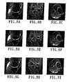
- FIGS. 8A , 8 B and 8 Cshow axial, sagittal and coronal slices, respectively, of simple fusion without registration.
- FIGS. 8D , 8 E and 8 Fshow the same slices with simple fusion after registration.
- FIGS. 8G , 8 H and 8 Ishow the same slices with complete image fusion.
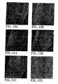
- FIGS. 9A-9Ishow fusion of orthogonal images without correlation.
- FIGS. 9A , 9 B and 9 Cshow axial views of the original MRI sagittal scan, the original axial scan and the fused image, respectively, for an axial view.
- FIGS. 9D , 9 E and 9 Fshow the same for a sagittal view.
- FIGS. 9G , 9 H and 9 Ishow the same for a coronal view.
Landscapes
- Physics & Mathematics (AREA)
- Health & Medical Sciences (AREA)
- Life Sciences & Earth Sciences (AREA)
- High Energy & Nuclear Physics (AREA)
- Nuclear Medicine, Radiotherapy & Molecular Imaging (AREA)
- Heart & Thoracic Surgery (AREA)
- Animal Behavior & Ethology (AREA)
- Pathology (AREA)
- Engineering & Computer Science (AREA)
- Biomedical Technology (AREA)
- Radiology & Medical Imaging (AREA)
- Medical Informatics (AREA)
- Molecular Biology (AREA)
- Surgery (AREA)
- Biophysics (AREA)
- General Health & Medical Sciences (AREA)
- Public Health (AREA)
- Veterinary Medicine (AREA)
- Optics & Photonics (AREA)
- Spectroscopy & Molecular Physics (AREA)
- Condensed Matter Physics & Semiconductors (AREA)
- General Physics & Mathematics (AREA)
- Magnetic Resonance Imaging Apparatus (AREA)
Abstract
Description
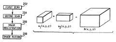
If u(x, y, z) is just a displaced version of v(x, y, z), or in other words, u(x, y, z)=v(x+Δx, y+Δy, z+Δz), then the maximum is at (−Δx, −Δy, −Δz), the displacement between the functions.
g1(x,y,z)=f(x,y,z)*w1(x,y,z)*Π(x,y,z)
g2(x,y,z)=f(x+Δx,y+yΔy,z+Δz)*w2(x,y,z)*Π(x,y,z)
where w1(x, y, z) and w2(x, y, z) are the 3D windows for the two orthogonal scanning directions, (Δx, Δy, Δz) is a small displacement, and Π(x, y, z) is the sampling function. Therefore, the correlation of the two sampled volumes is
r(x,y,z)=g1(x,y,z)*g2(x,y,z)
=f(x+Δx,y+Δy,z+Δz)*f(x,y,z)*w2(x,y,z)*Π(x,y,z).
That is just a blurred version of the original correlation; the exact location of the maxima is shaped by the blurring function h(x, y, z)=w1(x, y, z)* w2(x, y, z). That is, the correlation is distorted by the function h(x, y, z).
r(x,y,z)=g1(x,y,z)*g2(x,y,z)
=[f(x+Δx,y+Δy,z+Δz)*f(x,y,z)+
f(x+Δx,y+Δy,z+Δz)*n1(x,y,z)+
f(x,y,z)*n2(x,y,z)]*h(x,y,z)* Π(x,y,z),
and the maximum is no longer guaranteed to be given by the displacement, especially for functions with smooth autocorrelation functions like standard MRI. The smooth autocorrelation functions make the error a function of the noise power. Autocorrelation functions whose shapes are closer to a Dirac delta function δ(x, y, z) are less sensitive to noise, which is the reason why many registration algorithms work with edges. The autocorrelation function of the gradient magnitude of standard MRI is closer to a Dirac delta function. Therefore, the registration of the gradient is less sensitive to noise.
where
where δx, δy, δz are the sampling rates, and l(x, y, z) is a low pass filter used to remove noise from the images and to compensate the differences between in-slice sampling and inter-slice sampling.
g(x,y,z)=h1(x/sd,y,z)+h2(x,y/sd,z),
where h1, h2are two functions which are back projected in such a way that
That represents a linear system with the same number of knowns as unknowns. The known values are the observed image voxels, while the values to back-project which match the observation are estimated. Noise and inhomogeneous sampling make the problem a little bit harder; but that linear system can efficiently be solved using projection on convex sets (POCS). Although, in theory, all the components have to be orthogonally projected, it can be shown that the following projecting scheme also works:
where 0<α<1, n=the window size of w1, m=the window size of w2, h10(x, y, z)=g(x, y, z) and h20(x, y, z)=g2(x, y, z) are the initial guesses for the estimation of back-projected functions. The advantage of that approach over standard orthogonal projection is that is equations are simpler and that they can be implemented efficiently on a computer.
and the covariance matrix is defined as
where M is the number of voxels in the image.
y=A(x−m)x
is the discrete K-L transform, and yi, i=1, 2, . . . N, are the components of a multispectral image.
Claims (18)
Priority Applications (9)
| Application Number | Priority Date | Filing Date | Title |
|---|---|---|---|
| US09/540,524US6998841B1 (en) | 2000-03-31 | 2000-03-31 | Method and system which forms an isotropic, high-resolution, three-dimensional diagnostic image of a subject from two-dimensional image data scans |
| JP2001573103AJP2004525654A (en) | 2000-03-31 | 2001-04-02 | Magnetic resonance imaging system and method |
| AU2001251150AAU2001251150A1 (en) | 2000-03-31 | 2001-04-02 | Magnetic resonance imaging with resolution and contrast enhancement |
| CA002405000ACA2405000A1 (en) | 2000-03-31 | 2001-04-02 | Magnetic resonance imaging with resolution and contrast enhancement |
| TW090107831ATW570771B (en) | 2000-03-31 | 2001-04-02 | Magnetic resonance imaging with resolution and contrast enhancement |
| PCT/US2001/010308WO2001075483A1 (en) | 2000-03-31 | 2001-04-02 | Magnetic resonance imaging with resolution and contrast enhancement |
| EP01924501AEP1295152A1 (en) | 2000-03-31 | 2001-04-02 | Magnetic resonance imaging with resolution and contrast enhancement |
| US11/110,717US6984981B2 (en) | 2000-03-31 | 2005-04-21 | Magnetic resonance method and system forming an isotropic, high resolution, three-dimensional diagnostic image of a subject from two-dimensional image data scans |
| US11/320,743US20060122486A1 (en) | 2000-03-31 | 2005-12-30 | Magnetic resonance imaging with resolution and contrast enhancement |
Applications Claiming Priority (1)
| Application Number | Priority Date | Filing Date | Title |
|---|---|---|---|
| US09/540,524US6998841B1 (en) | 2000-03-31 | 2000-03-31 | Method and system which forms an isotropic, high-resolution, three-dimensional diagnostic image of a subject from two-dimensional image data scans |
Related Child Applications (1)
| Application Number | Title | Priority Date | Filing Date |
|---|---|---|---|
| US11/110,717DivisionUS6984981B2 (en) | 2000-03-31 | 2005-04-21 | Magnetic resonance method and system forming an isotropic, high resolution, three-dimensional diagnostic image of a subject from two-dimensional image data scans |
Publications (1)
| Publication Number | Publication Date |
|---|---|
| US6998841B1true US6998841B1 (en) | 2006-02-14 |
Family
ID=24155815
Family Applications (3)
| Application Number | Title | Priority Date | Filing Date |
|---|---|---|---|
| US09/540,524Expired - LifetimeUS6998841B1 (en) | 2000-03-31 | 2000-03-31 | Method and system which forms an isotropic, high-resolution, three-dimensional diagnostic image of a subject from two-dimensional image data scans |
| US11/110,717Expired - LifetimeUS6984981B2 (en) | 2000-03-31 | 2005-04-21 | Magnetic resonance method and system forming an isotropic, high resolution, three-dimensional diagnostic image of a subject from two-dimensional image data scans |
| US11/320,743AbandonedUS20060122486A1 (en) | 2000-03-31 | 2005-12-30 | Magnetic resonance imaging with resolution and contrast enhancement |
Family Applications After (2)
| Application Number | Title | Priority Date | Filing Date |
|---|---|---|---|
| US11/110,717Expired - LifetimeUS6984981B2 (en) | 2000-03-31 | 2005-04-21 | Magnetic resonance method and system forming an isotropic, high resolution, three-dimensional diagnostic image of a subject from two-dimensional image data scans |
| US11/320,743AbandonedUS20060122486A1 (en) | 2000-03-31 | 2005-12-30 | Magnetic resonance imaging with resolution and contrast enhancement |
Country Status (7)
| Country | Link |
|---|---|
| US (3) | US6998841B1 (en) |
| EP (1) | EP1295152A1 (en) |
| JP (1) | JP2004525654A (en) |
| AU (1) | AU2001251150A1 (en) |
| CA (1) | CA2405000A1 (en) |
| TW (1) | TW570771B (en) |
| WO (1) | WO2001075483A1 (en) |
Cited By (43)
| Publication number | Priority date | Publication date | Assignee | Title |
|---|---|---|---|---|
| US20020087274A1 (en)* | 1998-09-14 | 2002-07-04 | Alexander Eugene J. | Assessing the condition of a joint and preventing damage |
| US20030055502A1 (en)* | 2001-05-25 | 2003-03-20 | Philipp Lang | Methods and compositions for articular resurfacing |
| US20040153079A1 (en)* | 2002-11-07 | 2004-08-05 | Imaging Therapeutics, Inc. | Methods for determining meniscal size and shape and for devising treatment |
| US20040167390A1 (en)* | 1998-09-14 | 2004-08-26 | Alexander Eugene J. | Assessing the condition of a joint and devising treatment |
| US20040204644A1 (en)* | 2002-12-04 | 2004-10-14 | Imaging Therapeutics, Inc. | Fusion of multiple imaging planes for isotropic imaging in MRI and quantitative image analysis using isotropic or near-isotropic imaging |
| US20040204760A1 (en)* | 2001-05-25 | 2004-10-14 | Imaging Therapeutics, Inc. | Patient selectable knee arthroplasty devices |
| US20040249314A1 (en)* | 2003-06-09 | 2004-12-09 | Salla Prathyusha K. | Tempero-spatial physiological signal detection method and apparatus |
| US20050267584A1 (en)* | 2001-05-25 | 2005-12-01 | Burdulis Albert G Jr | Patient selectable knee joint arthroplasty devices |
| US20050285947A1 (en)* | 2004-06-21 | 2005-12-29 | Grindstaff Gene A | Real-time stabilization |
| US20060064004A1 (en)* | 2004-09-22 | 2006-03-23 | Kabushiki Kaisha Toshiba | Magnetic resonance imaging apparatus and magnetic resonance imaging method |
| US20060082200A1 (en)* | 2004-10-15 | 2006-04-20 | Tom Woellert | Harness adjustment mechanism for a child vehicle seat |
| US20060107706A1 (en)* | 2004-11-24 | 2006-05-25 | Samsung Electronics Co., Ltd. | Washing machine |
| US20060122486A1 (en)* | 2000-03-31 | 2006-06-08 | Jose Tamez-Pena | Magnetic resonance imaging with resolution and contrast enhancement |
| US20060132132A1 (en)* | 2004-12-21 | 2006-06-22 | General Electric Company | Method and system for MR scan acceleration using selective excitation and parallel transmission |
| US20060261810A1 (en)* | 2005-04-22 | 2006-11-23 | Hans-Peter Fautz | MRT imaging on the basis of conventional PPA reconstruction methods |
| US20070100462A1 (en)* | 2001-05-25 | 2007-05-03 | Conformis, Inc | Joint Arthroplasty Devices |
| US20070203430A1 (en)* | 1998-09-14 | 2007-08-30 | The Board Of Trustees Of The Leland Stanford Junior University | Assessing the Condition of a Joint and Assessing Cartilage Loss |
| US20070233269A1 (en)* | 2001-05-25 | 2007-10-04 | Conformis, Inc. | Interpositional Joint Implant |
| US20070276224A1 (en)* | 1998-09-14 | 2007-11-29 | The Board Of Trustees Of The Leland Stanford Junior University | Assessing the Condition of a Joint and Devising Treatment |
| US20080157764A1 (en)* | 2006-12-19 | 2008-07-03 | Hiroyuki Kabasawa | Magnetic resonance imaging apparatus, magnetic resonance imaging method, and diffusion tensor color map image generating apparatus |
| US20080195216A1 (en)* | 2001-05-25 | 2008-08-14 | Conformis, Inc. | Implant Device and Method for Manufacture |
| US20090058419A1 (en)* | 2007-08-29 | 2009-03-05 | Hiroyuki Kabasawa | Magnetic resonance imaging apparatus and magnetic resonance image displaying method |
| US20090067692A1 (en)* | 2004-11-10 | 2009-03-12 | Koninklijke Philips Electronics, N.V. | System and method for registration of medical images |
| EP2098990A1 (en) | 2008-03-04 | 2009-09-09 | Carestream Health, Inc. | Method for enhanced voxel resolution in MRI image |
| US20090228113A1 (en)* | 2008-03-05 | 2009-09-10 | Comformis, Inc. | Edge-Matched Articular Implant |
| US20090276045A1 (en)* | 2001-05-25 | 2009-11-05 | Conformis, Inc. | Devices and Methods for Treatment of Facet and Other Joints |
| US20100274534A1 (en)* | 2001-05-25 | 2010-10-28 | Conformis, Inc. | Automated Systems for Manufacturing Patient-Specific Orthopedic Implants and Instrumentation |
| US20110029091A1 (en)* | 2009-02-25 | 2011-02-03 | Conformis, Inc. | Patient-Adapted and Improved Orthopedic Implants, Designs, and Related Tools |
| US20110066245A1 (en)* | 2002-10-07 | 2011-03-17 | Conformis, Inc. | Minimally Invasive Joint Implant with 3-Dimensional Geometry Matching the Articular Surfaces |
| US20110071645A1 (en)* | 2009-02-25 | 2011-03-24 | Ray Bojarski | Patient-adapted and improved articular implants, designs and related guide tools |
| US20110071802A1 (en)* | 2009-02-25 | 2011-03-24 | Ray Bojarski | Patient-adapted and improved articular implants, designs and related guide tools |
| US20110087332A1 (en)* | 2001-05-25 | 2011-04-14 | Ray Bojarski | Patient-adapted and improved articular implants, designs and related guide tools |
| US20110144760A1 (en)* | 2004-01-05 | 2011-06-16 | Conformis, Inc. | Patient-Specific and Patient-Engineered Orthopedic Implants |
| WO2011106821A1 (en)* | 2010-03-03 | 2011-09-09 | Brain Research Institute Foundation Pty Ltd | Image processing system |
| US8480754B2 (en) | 2001-05-25 | 2013-07-09 | Conformis, Inc. | Patient-adapted and improved articular implants, designs and related guide tools |
| US20130221964A1 (en)* | 2012-02-27 | 2013-08-29 | Perinatronics Medical Systems, Inc. | Reducing noise in magnetic resonance imaging using conductive loops |
| US8556983B2 (en) | 2001-05-25 | 2013-10-15 | Conformis, Inc. | Patient-adapted and improved orthopedic implants, designs and related tools |
| US8682052B2 (en) | 2008-03-05 | 2014-03-25 | Conformis, Inc. | Implants for altering wear patterns of articular surfaces |
| US8735773B2 (en) | 2007-02-14 | 2014-05-27 | Conformis, Inc. | Implant device and method for manufacture |
| US9020788B2 (en) | 1997-01-08 | 2015-04-28 | Conformis, Inc. | Patient-adapted and improved articular implants, designs and related guide tools |
| WO2015112804A1 (en)* | 2014-01-23 | 2015-07-30 | The General Hospital Corporation | System and method for generating magnetic resonance imaging (mri) images using structures of the images |
| US9454643B2 (en) | 2013-05-02 | 2016-09-27 | Smith & Nephew, Inc. | Surface and image integration for model evaluation and landmark determination |
| US10551458B2 (en) | 2017-06-29 | 2020-02-04 | General Electric Company | Method and systems for iteratively reconstructing multi-shot, multi-acquisition MRI data |
Families Citing this family (25)
| Publication number | Priority date | Publication date | Assignee | Title |
|---|---|---|---|---|
| US20090222103A1 (en)* | 2001-05-25 | 2009-09-03 | Conformis, Inc. | Articular Implants Providing Lower Adjacent Cartilage Wear |
| FI20035205A0 (en) | 2003-11-12 | 2003-11-12 | Valtion Teknillinen | Procedure for combining short- and long-axis heart images when quantifying the heart |
| WO2006023354A1 (en)* | 2004-08-18 | 2006-03-02 | Virtualscopics, Llc | Use of multiple pulse sequences for 3d discrimination of sub-structures of the knee |
| US7920730B2 (en)* | 2005-10-07 | 2011-04-05 | Siemens Medical Solutions Usa, Inc. | Automatic bone detection in MRI images |
| WO2007062079A2 (en)* | 2005-11-21 | 2007-05-31 | Philipp Lang | Devices and methods for treating facet joints, uncovertebral joints, costovertebral joints and other joints |
| US20070165989A1 (en)* | 2005-11-30 | 2007-07-19 | Luis Serra Del Molino | Method and systems for diffusion tensor imaging |
| US7411393B2 (en)* | 2005-11-30 | 2008-08-12 | Bracco Imaging S.P.A. | Method and system for fiber tracking |
| US7279893B1 (en)* | 2006-04-20 | 2007-10-09 | General Electric Company | Receiver channel data combining in parallel mr imaging |
| US7372267B2 (en)* | 2006-05-04 | 2008-05-13 | University Of Basel | Method and apparatus for generation of magnetization transfer contrast in steady state free precession magnetic resonance imaging |
| US9089274B2 (en)* | 2011-01-31 | 2015-07-28 | Seiko Epson Corporation | Denoise MCG measurements |
| US8688192B2 (en)* | 2011-01-31 | 2014-04-01 | Seiko Epson Corporation | High-resolution magnetocardiogram restoration for cardiac electric current localization |
| KR102078335B1 (en)* | 2013-05-03 | 2020-02-17 | 삼성전자주식회사 | Medical imaging apparatus and control method for the same |
| BR112017004353A2 (en) | 2014-09-05 | 2017-12-05 | Hyperfine Res Inc | ferromagnetic magnification for magnetic resonance imaging |
| WO2016077417A1 (en) | 2014-11-11 | 2016-05-19 | Hyperfine Research, Inc. | Low field magnetic resonance methods and apparatus |
| KR102349449B1 (en)* | 2014-12-11 | 2022-01-10 | 삼성전자주식회사 | Magnetic resonance imaging apparatus and image processing method thereof |
| US9811881B2 (en)* | 2015-12-09 | 2017-11-07 | Goodrich Corporation | Off-band resolution emhancement |
| US10627464B2 (en) | 2016-11-22 | 2020-04-21 | Hyperfine Research, Inc. | Low-field magnetic resonance imaging methods and apparatus |
| US10718842B2 (en) | 2016-11-22 | 2020-07-21 | Hyperfine Research, Inc. | Systems and methods for automated detection in magnetic resonance images |
| US10539637B2 (en) | 2016-11-22 | 2020-01-21 | Hyperfine Research, Inc. | Portable magnetic resonance imaging methods and apparatus |
| US11039814B2 (en) | 2016-12-04 | 2021-06-22 | Exo Imaging, Inc. | Imaging devices having piezoelectric transducers |
| US11971477B2 (en) | 2018-09-25 | 2024-04-30 | Exo Imaging, Inc. | Imaging devices with selectively alterable characteristics |
| CA3124116A1 (en) | 2018-12-27 | 2020-07-02 | Exo Imaging, Inc. | Methods to maintain image quality in ultrasound imaging at reduced cost, size, and power |
| IL311310B2 (en) | 2020-03-05 | 2025-05-01 | Exo Imaging Inc | Ultrasonic imaging device with programmable anatomy and flow imaging |
| JP7744744B2 (en)* | 2020-12-17 | 2025-09-26 | 富士フイルム株式会社 | Image processing device, image processing method, and magnetic resonance imaging device |
| US11803939B2 (en) | 2021-04-28 | 2023-10-31 | Shanghai United Imaging Intelligence Co., Ltd. | Unsupervised interslice super-resolution for medical images |
Citations (23)
| Publication number | Priority date | Publication date | Assignee | Title |
|---|---|---|---|---|
| US5133357A (en) | 1991-02-07 | 1992-07-28 | General Electric Company | Quantitative measurement of blood flow using cylindrically localized fourier velocity encoding |
| US5245282A (en)* | 1991-06-28 | 1993-09-14 | University Of Virginia Alumni Patents Foundation | Three-dimensional magnetic resonance imaging |
| US5305204A (en) | 1989-07-19 | 1994-04-19 | Kabushiki Kaisha Toshiba | Digital image display apparatus with automatic window level and window width adjustment |
| US5374889A (en) | 1988-08-19 | 1994-12-20 | National Research Development Corporation | Magnetic resonance measurement |
| US5412563A (en) | 1993-09-16 | 1995-05-02 | General Electric Company | Gradient image segmentation method |
| US5442733A (en) | 1992-03-20 | 1995-08-15 | The Research Foundation Of State University Of New York | Method and apparatus for generating realistic images using a discrete representation |
| US5446384A (en) | 1993-12-27 | 1995-08-29 | General Electric Company | Simultaneous imaging of multiple spectroscopic components with magnetic resonance |
| US5633951A (en) | 1992-12-18 | 1997-05-27 | North America Philips Corporation | Registration of volumetric images which are relatively elastically deformed by matching surfaces |
| US5709208A (en) | 1994-04-08 | 1998-01-20 | The United States Of America As Represented By The Department Of Health And Human Services | Method and system for multidimensional localization and for rapid magnetic resonance spectroscopic imaging |
| US5749834A (en) | 1996-12-30 | 1998-05-12 | General Electric Company | Intersecting multislice MRI data acquistion method |
| WO1998024063A1 (en) | 1996-11-28 | 1998-06-04 | Picker Medical Systems, Ltd. | Ct systems with oblique image planes |
| US5786692A (en) | 1995-08-18 | 1998-07-28 | Brigham And Women's Hospital, Inc. | Line scan diffusion imaging |
| US5818231A (en) | 1992-05-15 | 1998-10-06 | University Of Washington | Quantitation and standardization of magnetic resonance measurements |
| US5825909A (en) | 1996-02-29 | 1998-10-20 | Eastman Kodak Company | Automated method and system for image segmentation in digital radiographic images |
| US5839440A (en) | 1994-06-17 | 1998-11-24 | Siemens Corporate Research, Inc. | Three-dimensional image registration method for spiral CT angiography |
| US5891030A (en) | 1997-01-24 | 1999-04-06 | Mayo Foundation For Medical Education And Research | System for two dimensional and three dimensional imaging of tubular structures in the human body |
| US5926568A (en) | 1997-06-30 | 1999-07-20 | The University Of North Carolina At Chapel Hill | Image object matching using core analysis and deformable shape loci |
| US5928146A (en) | 1996-03-15 | 1999-07-27 | Hitachi Medical Corporation | Inspection apparatus using nuclear magnetic resonance |
| US6031935A (en) | 1998-02-12 | 2000-02-29 | Kimmel; Zebadiah M. | Method and apparatus for segmenting images using constant-time deformable contours |
| US6239597B1 (en)* | 1999-10-14 | 2001-05-29 | General Electric Company | Method and apparatus for rapid T2 weighted MR image acquisition |
| US6480565B1 (en)* | 1999-11-18 | 2002-11-12 | University Of Rochester | Apparatus and method for cone beam volume computed tomography breast imaging |
| US6526305B1 (en)* | 1998-11-25 | 2003-02-25 | The Johns Hopkins University | Method of fiber reconstruction employing data acquired by magnetic resonance imaging |
| US20030135103A1 (en)* | 2001-11-12 | 2003-07-17 | Mistretta Charles A. | Three-dimensional phase contrast imaging using interleaved projection data |
Family Cites Families (8)
| Publication number | Priority date | Publication date | Assignee | Title |
|---|---|---|---|---|
| US4843322A (en)* | 1988-08-15 | 1989-06-27 | General Electric Company | Method for producing multi-slice NMR images |
| US5826568A (en)* | 1997-05-13 | 1998-10-27 | Dallas Metal Fabricators, Inc. | Ball pitching apparatus |
| US6539126B1 (en)* | 1998-04-17 | 2003-03-25 | Equinox Corporation | Visualization of local contrast for n-dimensional image data |
| WO2000019889A1 (en)* | 1998-10-08 | 2000-04-13 | University Of Kentucky Research Foundation | Methods and apparatus for in vivo identification and characterization of vulnerable atherosclerotic plaques |
| US6341257B1 (en)* | 1999-03-04 | 2002-01-22 | Sandia Corporation | Hybrid least squares multivariate spectral analysis methods |
| US6265875B1 (en)* | 1999-05-17 | 2001-07-24 | General Electric Company | Method and apparatus for efficient MRI tissue differentiation |
| JP2003528666A (en)* | 2000-03-24 | 2003-09-30 | コーニンクレッカ フィリップス エレクトロニクス エヌ ヴィ | Magnetic resonance imaging method by subsampling |
| US6998841B1 (en)* | 2000-03-31 | 2006-02-14 | Virtualscopics, Llc | Method and system which forms an isotropic, high-resolution, three-dimensional diagnostic image of a subject from two-dimensional image data scans |
- 2000
- 2000-03-31USUS09/540,524patent/US6998841B1/ennot_activeExpired - Lifetime
- 2001
- 2001-04-02TWTW090107831Apatent/TW570771B/enactive
- 2001-04-02CACA002405000Apatent/CA2405000A1/ennot_activeAbandoned
- 2001-04-02WOPCT/US2001/010308patent/WO2001075483A1/enactiveApplication Filing
- 2001-04-02EPEP01924501Apatent/EP1295152A1/ennot_activeWithdrawn
- 2001-04-02AUAU2001251150Apatent/AU2001251150A1/ennot_activeAbandoned
- 2001-04-02JPJP2001573103Apatent/JP2004525654A/enactivePending
- 2005
- 2005-04-21USUS11/110,717patent/US6984981B2/ennot_activeExpired - Lifetime
- 2005-12-30USUS11/320,743patent/US20060122486A1/ennot_activeAbandoned
Patent Citations (24)
| Publication number | Priority date | Publication date | Assignee | Title |
|---|---|---|---|---|
| US5374889A (en) | 1988-08-19 | 1994-12-20 | National Research Development Corporation | Magnetic resonance measurement |
| US5305204A (en) | 1989-07-19 | 1994-04-19 | Kabushiki Kaisha Toshiba | Digital image display apparatus with automatic window level and window width adjustment |
| US5133357A (en) | 1991-02-07 | 1992-07-28 | General Electric Company | Quantitative measurement of blood flow using cylindrically localized fourier velocity encoding |
| US5245282A (en)* | 1991-06-28 | 1993-09-14 | University Of Virginia Alumni Patents Foundation | Three-dimensional magnetic resonance imaging |
| US5442733A (en) | 1992-03-20 | 1995-08-15 | The Research Foundation Of State University Of New York | Method and apparatus for generating realistic images using a discrete representation |
| US5818231A (en) | 1992-05-15 | 1998-10-06 | University Of Washington | Quantitation and standardization of magnetic resonance measurements |
| US5633951A (en) | 1992-12-18 | 1997-05-27 | North America Philips Corporation | Registration of volumetric images which are relatively elastically deformed by matching surfaces |
| US5412563A (en) | 1993-09-16 | 1995-05-02 | General Electric Company | Gradient image segmentation method |
| US5446384A (en) | 1993-12-27 | 1995-08-29 | General Electric Company | Simultaneous imaging of multiple spectroscopic components with magnetic resonance |
| US5709208A (en) | 1994-04-08 | 1998-01-20 | The United States Of America As Represented By The Department Of Health And Human Services | Method and system for multidimensional localization and for rapid magnetic resonance spectroscopic imaging |
| US5839440A (en) | 1994-06-17 | 1998-11-24 | Siemens Corporate Research, Inc. | Three-dimensional image registration method for spiral CT angiography |
| US5786692A (en) | 1995-08-18 | 1998-07-28 | Brigham And Women's Hospital, Inc. | Line scan diffusion imaging |
| US5825909A (en) | 1996-02-29 | 1998-10-20 | Eastman Kodak Company | Automated method and system for image segmentation in digital radiographic images |
| US5928146A (en) | 1996-03-15 | 1999-07-27 | Hitachi Medical Corporation | Inspection apparatus using nuclear magnetic resonance |
| WO1998024063A1 (en) | 1996-11-28 | 1998-06-04 | Picker Medical Systems, Ltd. | Ct systems with oblique image planes |
| US6178220B1 (en) | 1996-11-28 | 2001-01-23 | Marconi Medical Systems Israel Ltd. | CT systems with oblique image planes |
| US5749834A (en) | 1996-12-30 | 1998-05-12 | General Electric Company | Intersecting multislice MRI data acquistion method |
| US5891030A (en) | 1997-01-24 | 1999-04-06 | Mayo Foundation For Medical Education And Research | System for two dimensional and three dimensional imaging of tubular structures in the human body |
| US5926568A (en) | 1997-06-30 | 1999-07-20 | The University Of North Carolina At Chapel Hill | Image object matching using core analysis and deformable shape loci |
| US6031935A (en) | 1998-02-12 | 2000-02-29 | Kimmel; Zebadiah M. | Method and apparatus for segmenting images using constant-time deformable contours |
| US6526305B1 (en)* | 1998-11-25 | 2003-02-25 | The Johns Hopkins University | Method of fiber reconstruction employing data acquired by magnetic resonance imaging |
| US6239597B1 (en)* | 1999-10-14 | 2001-05-29 | General Electric Company | Method and apparatus for rapid T2 weighted MR image acquisition |
| US6480565B1 (en)* | 1999-11-18 | 2002-11-12 | University Of Rochester | Apparatus and method for cone beam volume computed tomography breast imaging |
| US20030135103A1 (en)* | 2001-11-12 | 2003-07-17 | Mistretta Charles A. | Three-dimensional phase contrast imaging using interleaved projection data |
Non-Patent Citations (11)
| Title |
|---|
| Bushberg et al., textbook "The Essential Physics of Medical Imaging", Williams and Wilkins Philadelphia pp. 325-327; 332-333; 336-339 1994.* |
| Catherine Westbrook and Carolyn Kaut textbook "MRI in Practice Second Edition" Blackwell Science, Inc., pp. 47-57 and pp. 101-103 1998.* |
| E.A. Ashton, et al., Segmentation and Feature Extraction Techniques, with Applications to MRI Head Studies, IEEE Transactions on Medical Imaging, vol. 16, pp. 365-371, 1997. |
| Henson M M; et al., "Imaging the cochlea by magnetic resonance microscopy" Hearing research (Netherlands) May 1994, 75 (1-2) pp. 75-80, ISSN 0378-5955.* |
| Higashi M "FASE" (fast advanced spin echo) Nippon rinsho. Japanese journal of clinical medicine (Japan) Nov. 1998, 56 (11) p2783-91, ISSN 0047-1852.* |
| Jagath C. Rajapakse, et al., Statistical Approach to Segmentation of Single-Channel Cerebral MR Images, IEEE Transactions on medical imaging, vol. 16, No. 2, pp. 176-186, 1997. |
| José G. Tamez Peña, et al., Automatic Statistical Segmentation of Medical Volumetric Images, IEEE Computer Vision and Pattern Recognition 98, pp 1-7. |
| M.W. Hansen, et al., "Relaxation Methods for Supervised Image Segmentation", IEEE Trans. Patt. Anal. Mach. Intel., vol. 19, pp. 949-962, 1997. |
| Mellin, A.F. et al, "Three dimensional magnetic resonance microangiography of rat neurovasculature" magnetic resonance in medicine vol. 32, No. 2, pp. 199-205 1994.* |
| W.E. Higgins, et al., "Extraction of Left-Ventricular Chamber from 3-D CT Images of the Heart", Transactions on Medical Imaging, vol. 9, No. 4, pp. 384-394, 1990. |
| W.M. Wells III et al., "Adaptive Segmentation of MRI Data", IEEE Transactions on Medical Imaging, pp. 429-440, 1996. |
Cited By (111)
| Publication number | Priority date | Publication date | Assignee | Title |
|---|---|---|---|---|
| US9020788B2 (en) | 1997-01-08 | 2015-04-28 | Conformis, Inc. | Patient-adapted and improved articular implants, designs and related guide tools |
| US8265730B2 (en) | 1998-09-14 | 2012-09-11 | The Board Of Trustees Of The Leland Stanford Junior University | Assessing the condition of a joint and preventing damage |
| US8036729B2 (en) | 1998-09-14 | 2011-10-11 | The Board Of Trustees Of The Leland Stanford Junior University | Assessing the condition of a joint and devising treatment |
| US20040167390A1 (en)* | 1998-09-14 | 2004-08-26 | Alexander Eugene J. | Assessing the condition of a joint and devising treatment |
| US20020087274A1 (en)* | 1998-09-14 | 2002-07-04 | Alexander Eugene J. | Assessing the condition of a joint and preventing damage |
| US8862202B2 (en) | 1998-09-14 | 2014-10-14 | The Board Of Trustees Of The Leland Stanford Junior University | Assessing the condition of a joint and preventing damage |
| US8369926B2 (en) | 1998-09-14 | 2013-02-05 | The Board Of Trustees Of The Leland Stanford Junior University | Assessing the condition of a joint and devising treatment |
| US9286686B2 (en) | 1998-09-14 | 2016-03-15 | The Board Of Trustees Of The Leland Stanford Junior University | Assessing the condition of a joint and assessing cartilage loss |
| USRE43282E1 (en) | 1998-09-14 | 2012-03-27 | The Board Of Trustees Of The Leland Stanford Junior University | Assessing the condition of a joint and devising treatment |
| US8306601B2 (en) | 1998-09-14 | 2012-11-06 | The Board Of Trustees Of The Leland Stanford Junior University | Assessing the condition of a joint and devising treatment |
| US8112142B2 (en) | 1998-09-14 | 2012-02-07 | The Board Of Trustees Of The Leland Stanford Junior University | Assessing the condition of a joint and devising treatment |
| US20070203430A1 (en)* | 1998-09-14 | 2007-08-30 | The Board Of Trustees Of The Leland Stanford Junior University | Assessing the Condition of a Joint and Assessing Cartilage Loss |
| US20070276224A1 (en)* | 1998-09-14 | 2007-11-29 | The Board Of Trustees Of The Leland Stanford Junior University | Assessing the Condition of a Joint and Devising Treatment |
| US7881768B2 (en) | 1998-09-14 | 2011-02-01 | The Board Of Trustees Of The Leland Stanford Junior University | Assessing the condition of a joint and devising treatment |
| US20080015433A1 (en)* | 1998-09-14 | 2008-01-17 | The Board Of Trustees Of The Leland Stanford Junior University | Assessing the Condition of a Joint and Devising Treatment |
| US20060122486A1 (en)* | 2000-03-31 | 2006-06-08 | Jose Tamez-Pena | Magnetic resonance imaging with resolution and contrast enhancement |
| US8945230B2 (en) | 2001-05-25 | 2015-02-03 | Conformis, Inc. | Patient selectable knee joint arthroplasty devices |
| US9055953B2 (en) | 2001-05-25 | 2015-06-16 | Conformis, Inc. | Methods and compositions for articular repair |
| US20070233269A1 (en)* | 2001-05-25 | 2007-10-04 | Conformis, Inc. | Interpositional Joint Implant |
| US20070100462A1 (en)* | 2001-05-25 | 2007-05-03 | Conformis, Inc | Joint Arthroplasty Devices |
| US9877790B2 (en) | 2001-05-25 | 2018-01-30 | Conformis, Inc. | Tibial implant and systems with variable slope |
| US9775680B2 (en) | 2001-05-25 | 2017-10-03 | Conformis, Inc. | Patient-adapted and improved articular implants, designs and related guide tools |
| US20080195216A1 (en)* | 2001-05-25 | 2008-08-14 | Conformis, Inc. | Implant Device and Method for Manufacture |
| US9700971B2 (en) | 2001-05-25 | 2017-07-11 | Conformis, Inc. | Implant device and method for manufacture |
| US9603711B2 (en) | 2001-05-25 | 2017-03-28 | Conformis, Inc. | Patient-adapted and improved articular implants, designs and related guide tools |
| US9495483B2 (en) | 2001-05-25 | 2016-11-15 | Conformis, Inc. | Automated Systems for manufacturing patient-specific orthopedic implants and instrumentation |
| US9439767B2 (en) | 2001-05-25 | 2016-09-13 | Conformis, Inc. | Patient-adapted and improved articular implants, designs and related guide tools |
| US9387079B2 (en) | 2001-05-25 | 2016-07-12 | Conformis, Inc. | Patient-adapted and improved articular implants, designs and related guide tools |
| US9333085B2 (en) | 2001-05-25 | 2016-05-10 | Conformis, Inc. | Patient selectable knee arthroplasty devices |
| US20090276045A1 (en)* | 2001-05-25 | 2009-11-05 | Conformis, Inc. | Devices and Methods for Treatment of Facet and Other Joints |
| US20090306676A1 (en)* | 2001-05-25 | 2009-12-10 | Conformis, Inc. | Methods and compositions for articular repair |
| US9308091B2 (en) | 2001-05-25 | 2016-04-12 | Conformis, Inc. | Devices and methods for treatment of facet and other joints |
| US20090312805A1 (en)* | 2001-05-25 | 2009-12-17 | Conformis, Inc. | Methods and compositions for articular repair |
| US20030055502A1 (en)* | 2001-05-25 | 2003-03-20 | Philipp Lang | Methods and compositions for articular resurfacing |
| US9186254B2 (en) | 2001-05-25 | 2015-11-17 | Conformis, Inc. | Patient selectable knee arthroplasty devices |
| US20050267584A1 (en)* | 2001-05-25 | 2005-12-01 | Burdulis Albert G Jr | Patient selectable knee joint arthroplasty devices |
| US8974539B2 (en) | 2001-05-25 | 2015-03-10 | Conformis, Inc. | Patient-adapted and improved articular implants, designs and related guide tools |
| US20100274534A1 (en)* | 2001-05-25 | 2010-10-28 | Conformis, Inc. | Automated Systems for Manufacturing Patient-Specific Orthopedic Implants and Instrumentation |
| US20100305708A1 (en)* | 2001-05-25 | 2010-12-02 | Conformis, Inc. | Patient Selectable Knee Joint Arthroplasty Devices |
| US8926706B2 (en) | 2001-05-25 | 2015-01-06 | Conformis, Inc. | Patient-adapted and improved articular implants, designs and related guide tools |
| US20100329530A1 (en)* | 2001-05-25 | 2010-12-30 | Conformis, Inc. | Patient Selectable Knee Joint Arthroplasty Devices |
| US8906107B2 (en) | 2001-05-25 | 2014-12-09 | Conformis, Inc. | Patient-adapted and improved orthopedic implants, designs and related tools |
| US8882847B2 (en) | 2001-05-25 | 2014-11-11 | Conformis, Inc. | Patient selectable knee joint arthroplasty devices |
| US8234097B2 (en) | 2001-05-25 | 2012-07-31 | Conformis, Inc. | Automated systems for manufacturing patient-specific orthopedic implants and instrumentation |
| US20040204760A1 (en)* | 2001-05-25 | 2004-10-14 | Imaging Therapeutics, Inc. | Patient selectable knee arthroplasty devices |
| US8768028B2 (en) | 2001-05-25 | 2014-07-01 | Conformis, Inc. | Methods and compositions for articular repair |
| US20110087332A1 (en)* | 2001-05-25 | 2011-04-14 | Ray Bojarski | Patient-adapted and improved articular implants, designs and related guide tools |
| US8337507B2 (en) | 2001-05-25 | 2012-12-25 | Conformis, Inc. | Methods and compositions for articular repair |
| US8690945B2 (en) | 2001-05-25 | 2014-04-08 | Conformis, Inc. | Patient selectable knee arthroplasty devices |
| US8617242B2 (en) | 2001-05-25 | 2013-12-31 | Conformis, Inc. | Implant device and method for manufacture |
| US8556983B2 (en) | 2001-05-25 | 2013-10-15 | Conformis, Inc. | Patient-adapted and improved orthopedic implants, designs and related tools |
| US8545569B2 (en) | 2001-05-25 | 2013-10-01 | Conformis, Inc. | Patient selectable knee arthroplasty devices |
| US8480754B2 (en) | 2001-05-25 | 2013-07-09 | Conformis, Inc. | Patient-adapted and improved articular implants, designs and related guide tools |
| US8343218B2 (en) | 2001-05-25 | 2013-01-01 | Conformis, Inc. | Methods and compositions for articular repair |
| US8709089B2 (en) | 2002-10-07 | 2014-04-29 | Conformis, Inc. | Minimally invasive joint implant with 3-dimensional geometry matching the articular surfaces |
| US20110066245A1 (en)* | 2002-10-07 | 2011-03-17 | Conformis, Inc. | Minimally Invasive Joint Implant with 3-Dimensional Geometry Matching the Articular Surfaces |
| US20040153079A1 (en)* | 2002-11-07 | 2004-08-05 | Imaging Therapeutics, Inc. | Methods for determining meniscal size and shape and for devising treatment |
| US8077950B2 (en) | 2002-11-07 | 2011-12-13 | Conformis, Inc. | Methods for determining meniscal size and shape and for devising treatment |
| US20100303317A1 (en)* | 2002-11-07 | 2010-12-02 | Conformis, Inc. | Methods for Determining Meniscal Size and Shape and for Devising Treatment |
| US8965088B2 (en) | 2002-11-07 | 2015-02-24 | Conformis, Inc. | Methods for determining meniscal size and shape and for devising treatment |
| US7796791B2 (en) | 2002-11-07 | 2010-09-14 | Conformis, Inc. | Methods for determining meniscal size and shape and for devising treatment |
| US8932363B2 (en) | 2002-11-07 | 2015-01-13 | Conformis, Inc. | Methods for determining meniscal size and shape and for devising treatment |
| US8634617B2 (en) | 2002-11-07 | 2014-01-21 | Conformis, Inc. | Methods for determining meniscal size and shape and for devising treatment |
| US8638998B2 (en) | 2002-12-04 | 2014-01-28 | Conformis, Inc. | Fusion of multiple imaging planes for isotropic imaging in MRI and quantitative image analysis using isotropic or near-isotropic imaging |
| US20040204644A1 (en)* | 2002-12-04 | 2004-10-14 | Imaging Therapeutics, Inc. | Fusion of multiple imaging planes for isotropic imaging in MRI and quantitative image analysis using isotropic or near-isotropic imaging |
| US8094900B2 (en) | 2002-12-04 | 2012-01-10 | Conformis, Inc. | Fusion of multiple imaging planes for isotropic imaging in MRI and quantitative image analysis using isotropic or near-isotropic imaging |
| US7634119B2 (en) | 2002-12-04 | 2009-12-15 | Conformis, Inc. | Fusion of multiple imaging planes for isotropic imaging in MRI and quantitative image analysis using isotropic or near-isotropic imaging |
| US20100054572A1 (en)* | 2002-12-04 | 2010-03-04 | Conformis, Inc. | Fusion of Multiple Imaging Planes for Isotropic Imaging in MRI and Quantitative Image Analysis using Isotropic or Near-isotropic Imaging |
| US9687945B2 (en) | 2002-12-04 | 2017-06-27 | Conformis, Inc. | Fusion of multiple imaging planes for isotropic imaging in MRI and quantitative image analysis using isotropic or near-isotropic imaging |
| US20040249314A1 (en)* | 2003-06-09 | 2004-12-09 | Salla Prathyusha K. | Tempero-spatial physiological signal detection method and apparatus |
| US8064979B2 (en)* | 2003-06-09 | 2011-11-22 | General Electric Company | Tempero-spatial physiological signal detection method and apparatus |
| US10085839B2 (en) | 2004-01-05 | 2018-10-02 | Conformis, Inc. | Patient-specific and patient-engineered orthopedic implants |
| US20110144760A1 (en)* | 2004-01-05 | 2011-06-16 | Conformis, Inc. | Patient-Specific and Patient-Engineered Orthopedic Implants |
| US20050285947A1 (en)* | 2004-06-21 | 2005-12-29 | Grindstaff Gene A | Real-time stabilization |
| US7256580B2 (en)* | 2004-09-22 | 2007-08-14 | Kabushiki Kaisha Toshiba | Magnetic resonance imaging apparatus and magnetic resonance imaging method |
| US20060064004A1 (en)* | 2004-09-22 | 2006-03-23 | Kabushiki Kaisha Toshiba | Magnetic resonance imaging apparatus and magnetic resonance imaging method |
| US20060082200A1 (en)* | 2004-10-15 | 2006-04-20 | Tom Woellert | Harness adjustment mechanism for a child vehicle seat |
| US20090067692A1 (en)* | 2004-11-10 | 2009-03-12 | Koninklijke Philips Electronics, N.V. | System and method for registration of medical images |
| US8244007B2 (en)* | 2004-11-10 | 2012-08-14 | Koninklijke Philips Electronics N.V. | System and method for registration of medical images based on insufficiently similar image areas |
| US20060107706A1 (en)* | 2004-11-24 | 2006-05-25 | Samsung Electronics Co., Ltd. | Washing machine |
| US20060132132A1 (en)* | 2004-12-21 | 2006-06-22 | General Electric Company | Method and system for MR scan acceleration using selective excitation and parallel transmission |
| US20060261810A1 (en)* | 2005-04-22 | 2006-11-23 | Hans-Peter Fautz | MRT imaging on the basis of conventional PPA reconstruction methods |
| US7511489B2 (en)* | 2005-04-22 | 2009-03-31 | Siemens Aktiengesellschaft | MRT imaging on the basis of conventional PPA reconstruction methods |
| US20080157764A1 (en)* | 2006-12-19 | 2008-07-03 | Hiroyuki Kabasawa | Magnetic resonance imaging apparatus, magnetic resonance imaging method, and diffusion tensor color map image generating apparatus |
| US7683616B2 (en) | 2006-12-19 | 2010-03-23 | Ge Medical Systems Global Technology Company, Llc | Magnetic resonance imaging apparatus, magnetic resonance imaging method, and diffusion tensor color map image generating apparatus |
| US8735773B2 (en) | 2007-02-14 | 2014-05-27 | Conformis, Inc. | Implant device and method for manufacture |
| US20090058419A1 (en)* | 2007-08-29 | 2009-03-05 | Hiroyuki Kabasawa | Magnetic resonance imaging apparatus and magnetic resonance image displaying method |
| US7671592B2 (en) | 2007-08-29 | 2010-03-02 | Ge Medical Systems Global Technology Company, Llc | Magnetic resonance imaging apparatus and magnetic resonance image displaying method |
| EP2098990A1 (en) | 2008-03-04 | 2009-09-09 | Carestream Health, Inc. | Method for enhanced voxel resolution in MRI image |
| US8472689B2 (en) | 2008-03-04 | 2013-06-25 | Carestream Health, Inc. | Method for enhanced voxel resolution in MRI image |
| US20090226067A1 (en)* | 2008-03-04 | 2009-09-10 | Carestream Health, Inc. | Method for enhanced voxel resolution in mri image |
| US9700420B2 (en) | 2008-03-05 | 2017-07-11 | Conformis, Inc. | Implants for altering wear patterns of articular surfaces |
| US20090228113A1 (en)* | 2008-03-05 | 2009-09-10 | Comformis, Inc. | Edge-Matched Articular Implant |
| US8682052B2 (en) | 2008-03-05 | 2014-03-25 | Conformis, Inc. | Implants for altering wear patterns of articular surfaces |
| US9180015B2 (en) | 2008-03-05 | 2015-11-10 | Conformis, Inc. | Implants for altering wear patterns of articular surfaces |
| US9320620B2 (en) | 2009-02-24 | 2016-04-26 | Conformis, Inc. | Patient-adapted and improved articular implants, designs and related guide tools |
| US20110029091A1 (en)* | 2009-02-25 | 2011-02-03 | Conformis, Inc. | Patient-Adapted and Improved Orthopedic Implants, Designs, and Related Tools |
| US20110071645A1 (en)* | 2009-02-25 | 2011-03-24 | Ray Bojarski | Patient-adapted and improved articular implants, designs and related guide tools |
| US8771365B2 (en) | 2009-02-25 | 2014-07-08 | Conformis, Inc. | Patient-adapted and improved orthopedic implants, designs, and related tools |
| US20110071802A1 (en)* | 2009-02-25 | 2011-03-24 | Ray Bojarski | Patient-adapted and improved articular implants, designs and related guide tools |
| WO2011106821A1 (en)* | 2010-03-03 | 2011-09-09 | Brain Research Institute Foundation Pty Ltd | Image processing system |
| US9720062B2 (en) | 2010-03-03 | 2017-08-01 | Brain Research Institute Foundation Pty Ltd. | Image processing system |
| US8659297B2 (en)* | 2012-02-27 | 2014-02-25 | Perinatronics Medical Systems, Inc. | Reducing noise in magnetic resonance imaging using conductive loops |
| US20130221964A1 (en)* | 2012-02-27 | 2013-08-29 | Perinatronics Medical Systems, Inc. | Reducing noise in magnetic resonance imaging using conductive loops |
| US9454643B2 (en) | 2013-05-02 | 2016-09-27 | Smith & Nephew, Inc. | Surface and image integration for model evaluation and landmark determination |
| US9747688B2 (en) | 2013-05-02 | 2017-08-29 | Smith & Nephew, Inc. | Surface and image integration for model evaluation and landmark determination |
| US10586332B2 (en) | 2013-05-02 | 2020-03-10 | Smith & Nephew, Inc. | Surface and image integration for model evaluation and landmark determination |
| US11145121B2 (en) | 2013-05-02 | 2021-10-12 | Smith & Nephew, Inc. | Surface and image integration for model evaluation and landmark determination |
| US11704872B2 (en) | 2013-05-02 | 2023-07-18 | Smith & Nephew, Inc. | Surface and image integration for model evaluation and landmark determination |
| WO2015112804A1 (en)* | 2014-01-23 | 2015-07-30 | The General Hospital Corporation | System and method for generating magnetic resonance imaging (mri) images using structures of the images |
| US10551458B2 (en) | 2017-06-29 | 2020-02-04 | General Electric Company | Method and systems for iteratively reconstructing multi-shot, multi-acquisition MRI data |
Also Published As
| Publication number | Publication date |
|---|---|
| US20060122486A1 (en) | 2006-06-08 |
| WO2001075483A1 (en) | 2001-10-11 |
| JP2004525654A (en) | 2004-08-26 |
| AU2001251150A1 (en) | 2001-10-15 |
| CA2405000A1 (en) | 2001-10-11 |
| US6984981B2 (en) | 2006-01-10 |
| EP1295152A1 (en) | 2003-03-26 |
| US20050184730A1 (en) | 2005-08-25 |
| TW570771B (en) | 2004-01-11 |
Similar Documents
| Publication | Publication Date | Title |
|---|---|---|
| US6998841B1 (en) | Method and system which forms an isotropic, high-resolution, three-dimensional diagnostic image of a subject from two-dimensional image data scans | |
| JP3976684B2 (en) | Method and apparatus for reducing the effects of motion in images | |
| US6160398A (en) | Adaptive reconstruction of phased array NMR imagery | |
| US5602934A (en) | Adaptive digital image signal filtering | |
| US7024027B1 (en) | Method and apparatus for three-dimensional filtering of angiographic volume data | |
| US8810242B2 (en) | Spatial intensity correction for RF shading non-uniformities in MRI | |
| Jog et al. | Improving magnetic resonance resolution with supervised learning | |
| US7020314B1 (en) | Black blood angiography method and apparatus | |
| DE69706684T2 (en) | METHOD AND DEVICE FOR IMAGING ARTIFACT REDUCTION | |
| KR880001364B1 (en) | Nuclear magnetic resonance imaging data generation method | |
| US6724190B2 (en) | Retrospective selection and various types of image alignment to improve DTI SNR | |
| EP1506427B1 (en) | Real-time tractography | |
| JPWO2002056767A1 (en) | Parallel MR imaging using high-precision coil sensitivity map | |
| WO2003050761A2 (en) | Method for compensating for motion artifacts in magnetic resonance imaging by phase line prediction | |
| US6486667B1 (en) | Combination of fluid-attenuated inversion-recovery complex images acquired using magnetic resonance imaging | |
| US7218107B2 (en) | Adaptive image homogeneity correction for high field magnetic resonance imaging | |
| Vemuri et al. | Coil sensitivity estimation for optimal SNR reconstruction and intensity inhomogeneity correction in phased array MR imaging | |
| Simmons et al. | Improvements to the quality of MRI cluster analysis | |
| EP1176555A2 (en) | Image processing method and apparatus, recording medium, and imaging apparatus | |
| Patel et al. | A robust algorithm for reduction of truncation artifact in chemical shift images | |
| Chen et al. | Particle filtering for slice-to-volume motion correction in EPI based functional MRI | |
| Chen et al. | Renormalization method for inhomogeneity correction of MR images | |
| Kim et al. | Bayesian processing for fMRI | |
| Ro et al. | Local motion suppression in magnetic resonance imaging | |
| Machida et al. | 4896111 Method and system for improving resolution of images in magnetic resonance imaging |
Legal Events
| Date | Code | Title | Description |
|---|---|---|---|
| AS | Assignment | Owner name:UNIVERSITY OF ROCHESTER, NEW YORK Free format text:ASSIGNMENT OF ASSIGNORS INTEREST;ASSIGNORS:TAMEZ-PENA, JOSE;TOTTERMAN, SAARA M.S.;PARKER, KEVIN J.;REEL/FRAME:010718/0459 Effective date:20000330 | |
| AS | Assignment | Owner name:VIRTUALSCOPICS, LLC, NEW YORK Free format text:ASSIGNMENT OF ASSIGNORS INTEREST;ASSIGNOR:UNIVERSITY OF ROCHESTER, THE;REEL/FRAME:013056/0478 Effective date:20020405 | |
| STCF | Information on status: patent grant | Free format text:PATENTED CASE | |
| FPAY | Fee payment | Year of fee payment:4 | |
| FPAY | Fee payment | Year of fee payment:8 | |
| AS | Assignment | Owner name:VIRTUALSCOPICS INC., NEW YORK Free format text:ASSIGNMENT OF ASSIGNORS INTEREST;ASSIGNOR:VIRTUALSCOPICS NEW YORK, LLC;REEL/FRAME:038751/0772 Effective date:20160525 Owner name:VIRTUALSCOPICS NEW YORK, LLC, NEW YORK Free format text:CHANGE OF NAME;ASSIGNOR:VIRTUALSCOPICS, LLC;REEL/FRAME:038891/0584 Effective date:20000713 | |
| AS | Assignment | Owner name:HEALTHCARE FINANCIAL SOLUTIONS, LLC, MARYLAND Free format text:SECURITY INTEREST;ASSIGNOR:VIRTUALSCOPICS, LLC;REEL/FRAME:039188/0419 Effective date:20160719 | |
| FEPP | Fee payment procedure | Free format text:PAT HOLDER NO LONGER CLAIMS SMALL ENTITY STATUS, ENTITY STATUS SET TO UNDISCOUNTED (ORIGINAL EVENT CODE: STOL); ENTITY STATUS OF PATENT OWNER: LARGE ENTITY | |
| AS | Assignment | Owner name:VIRTUALSCOPICS, LLC, NEW YORK Free format text:ENTITY CONVERSION;ASSIGNOR:VIRTUALSCOPICS, INC.;REEL/FRAME:043107/0097 Effective date:20160608 | |
| AS | Assignment | Owner name:VIRTUALSCOPICS, LLC, PENNSYLVANIA Free format text:RELEASE BY SECURED PARTY;ASSIGNOR:HEALTHCARE FINANCIAL SOLUTIONS, LLC;REEL/FRAME:043168/0775 Effective date:20170712 | |
| AS | Assignment | Owner name:SUNTRUST BANK, AS ADMINISTRATIVE AGENT, GEORGIA Free format text:NOTICE OF GRANT OF SECURITY INTEREST IN PATENTS;ASSIGNOR:VIRTUALSCOPICS, LLC;REEL/FRAME:043267/0860 Effective date:20170712 | |
| FPAY | Fee payment | Year of fee payment:12 | |
| AS | Assignment | Owner name:VIRTUALSCOPICS, LLC, PENNSYLVANIA Free format text:TERMINATION AND RELEASE OF SECURITY INTEREST IN PATENTS;ASSIGNOR:TRUIST BANK (SUCCESSOR BY MERGER TO SUNTRUST BANK), AS ADMINISTRATIVE AGENT;REEL/FRAME:055272/0306 Effective date:20210209 |