US6997929B2 - Tissue distraction device - Google Patents
Tissue distraction deviceDownload PDFInfo
- Publication number
- US6997929B2 US6997929B2US10/846,235US84623504AUS6997929B2US 6997929 B2US6997929 B2US 6997929B2US 84623504 AUS84623504 AUS 84623504AUS 6997929 B2US6997929 B2US 6997929B2
- Authority
- US
- United States
- Prior art keywords
- wafer
- channel
- base wafer
- wafers
- track assembly
- Prior art date
- Legal status (The legal status is an assumption and is not a legal conclusion. Google has not performed a legal analysis and makes no representation as to the accuracy of the status listed.)
- Expired - Lifetime
Links
- 235000012431wafersNutrition0.000claimsabstractdescription660
- 238000003780insertionMethods0.000claimsabstractdescription68
- 230000037431insertionEffects0.000claimsabstractdescription68
- 239000012620biological materialSubstances0.000claimsabstractdescription6
- 230000014759maintenance of locationEffects0.000claimsdescription61
- 230000007246mechanismEffects0.000claimsdescription46
- 239000000463materialSubstances0.000claimsdescription24
- 229920003229poly(methyl methacrylate)Polymers0.000claimsdescription4
- 239000004926polymethyl methacrylateSubstances0.000claimsdescription4
- 238000000034methodMethods0.000abstractdescription20
- 210000001519tissueAnatomy0.000description36
- 210000000988bone and boneAnatomy0.000description25
- 206010010214Compression fractureDiseases0.000description19
- 230000033001locomotionEffects0.000description19
- 206010017076FractureDiseases0.000description14
- 239000000945fillerSubstances0.000description13
- 208000010392Bone FracturesDiseases0.000description10
- 230000004927fusionEffects0.000description10
- 239000002639bone cementSubstances0.000description7
- 238000011282treatmentMethods0.000description6
- 239000000853adhesiveSubstances0.000description5
- 230000001070adhesive effectEffects0.000description5
- 230000000712assemblyEffects0.000description4
- 238000000429assemblyMethods0.000description4
- 230000008901benefitEffects0.000description4
- 230000000994depressogenic effectEffects0.000description4
- 238000011065in-situ storageMethods0.000description4
- 238000001356surgical procedureMethods0.000description4
- 239000007943implantSubstances0.000description3
- 230000003993interactionEffects0.000description3
- 229920000642polymerPolymers0.000description3
- 230000009467reductionEffects0.000description3
- 210000004872soft tissueAnatomy0.000description3
- 210000002303tibiaAnatomy0.000description3
- 206010021639IncontinenceDiseases0.000description2
- 230000003416augmentationEffects0.000description2
- 230000009286beneficial effectEffects0.000description2
- 239000000560biocompatible materialSubstances0.000description2
- 230000008859changeEffects0.000description2
- 230000000881depressing effectEffects0.000description2
- 230000009977dual effectEffects0.000description2
- 230000003028elevating effectEffects0.000description2
- 230000006870functionEffects0.000description2
- 238000001727in vivoMethods0.000description2
- 208000014674injuryDiseases0.000description2
- 230000007774longtermEffects0.000description2
- 229910052751metalInorganic materials0.000description2
- 239000002184metalSubstances0.000description2
- 238000012986modificationMethods0.000description2
- 230000004048modificationEffects0.000description2
- 210000003491skinAnatomy0.000description2
- 239000010935stainless steelSubstances0.000description2
- 229910001220stainless steelInorganic materials0.000description2
- 238000011144upstream manufacturingMethods0.000description2
- 210000000707wristAnatomy0.000description2
- 208000008035Back PainDiseases0.000description1
- 206010010356Congenital anomalyDiseases0.000description1
- 229920001651CyanoacrylatePolymers0.000description1
- 206010015866ExtravasationDiseases0.000description1
- 206010061246Intervertebral disc degenerationDiseases0.000description1
- MWCLLHOVUTZFKS-UHFFFAOYSA-NMethyl cyanoacrylateChemical compoundCOC(=O)C(=C)C#NMWCLLHOVUTZFKS-UHFFFAOYSA-N0.000description1
- 208000002193PainDiseases0.000description1
- 206010041541Spinal compression fractureDiseases0.000description1
- 208000004367Tibial FracturesDiseases0.000description1
- RTAQQCXQSZGOHL-UHFFFAOYSA-NTitaniumChemical compound[Ti]RTAQQCXQSZGOHL-UHFFFAOYSA-N0.000description1
- 208000027418Wounds and injuryDiseases0.000description1
- 230000004913activationEffects0.000description1
- 230000001154acute effectEffects0.000description1
- 238000004026adhesive bondingMethods0.000description1
- 229910045601alloyInorganic materials0.000description1
- 239000000956alloySubstances0.000description1
- 230000004075alterationEffects0.000description1
- 238000002399angioplastyMethods0.000description1
- 238000013459approachMethods0.000description1
- 230000002146bilateral effectEffects0.000description1
- 239000000919ceramicSubstances0.000description1
- 238000006243chemical reactionMethods0.000description1
- 239000003795chemical substances by applicationSubstances0.000description1
- 238000004891communicationMethods0.000description1
- 239000002131composite materialSubstances0.000description1
- 230000006835compressionEffects0.000description1
- 238000007906compressionMethods0.000description1
- 239000002537cosmeticSubstances0.000description1
- 238000002316cosmetic surgeryMethods0.000description1
- 230000006378damageEffects0.000description1
- 230000005786degenerative changesEffects0.000description1
- 208000018180degenerative disc diseaseDiseases0.000description1
- 238000006073displacement reactionMethods0.000description1
- 239000003814drugSubstances0.000description1
- 229940079593drugDrugs0.000description1
- 238000002651drug therapyMethods0.000description1
- 230000000694effectsEffects0.000description1
- 238000000605extractionMethods0.000description1
- 230000036251extravasationEffects0.000description1
- 230000001815facial effectEffects0.000description1
- 238000010304firingMethods0.000description1
- 238000011902gastrointestinal surgeryMethods0.000description1
- 239000003102growth factorSubstances0.000description1
- 239000000017hydrogelSubstances0.000description1
- 238000002513implantationMethods0.000description1
- 238000002347injectionMethods0.000description1
- 239000007924injectionSubstances0.000description1
- 208000021600intervertebral disc degenerative diseaseDiseases0.000description1
- 239000011824nuclear materialSubstances0.000description1
- 238000011369optimal treatmentMethods0.000description1
- 230000002138osteoinductive effectEffects0.000description1
- 239000004033plasticSubstances0.000description1
- 229920003023plasticPolymers0.000description1
- 230000008569processEffects0.000description1
- 230000001737promoting effectEffects0.000description1
- 238000002271resectionMethods0.000description1
- 239000007787solidSubstances0.000description1
- 206010041569spinal fractureDiseases0.000description1
- 230000006641stabilisationEffects0.000description1
- 238000011105stabilizationMethods0.000description1
- 239000000126substanceSubstances0.000description1
- 238000011477surgical interventionMethods0.000description1
- 230000001225therapeutic effectEffects0.000description1
- 206010043827tibia fractureDiseases0.000description1
- 239000010936titaniumSubstances0.000description1
- 229910052719titaniumInorganic materials0.000description1
- 238000013519translationMethods0.000description1
- 230000008733traumaEffects0.000description1
Images


Classifications
- A—HUMAN NECESSITIES
- A61—MEDICAL OR VETERINARY SCIENCE; HYGIENE
- A61B—DIAGNOSIS; SURGERY; IDENTIFICATION
- A61B17/00—Surgical instruments, devices or methods
- A61B17/56—Surgical instruments or methods for treatment of bones or joints; Devices specially adapted therefor
- A61B17/58—Surgical instruments or methods for treatment of bones or joints; Devices specially adapted therefor for osteosynthesis, e.g. bone plates, screws or setting implements
- A61B17/88—Osteosynthesis instruments; Methods or means for implanting or extracting internal or external fixation devices
- A61B17/885—Tools for expanding or compacting bones or discs or cavities therein
- A61B17/8852—Tools for expanding or compacting bones or discs or cavities therein capable of being assembled or enlarged, or changing shape, inside the bone or disc
- A—HUMAN NECESSITIES
- A61—MEDICAL OR VETERINARY SCIENCE; HYGIENE
- A61B—DIAGNOSIS; SURGERY; IDENTIFICATION
- A61B17/00—Surgical instruments, devices or methods
- A61B17/02—Surgical instruments, devices or methods for holding wounds open, e.g. retractors; Tractors
- A61B17/025—Joint distractors
- A—HUMAN NECESSITIES
- A61—MEDICAL OR VETERINARY SCIENCE; HYGIENE
- A61B—DIAGNOSIS; SURGERY; IDENTIFICATION
- A61B17/00—Surgical instruments, devices or methods
- A61B17/12—Surgical instruments, devices or methods for ligaturing or otherwise compressing tubular parts of the body, e.g. blood vessels or umbilical cord
- A61B17/128—Surgical instruments, devices or methods for ligaturing or otherwise compressing tubular parts of the body, e.g. blood vessels or umbilical cord for applying or removing clamps or clips
- A61B17/1285—Surgical instruments, devices or methods for ligaturing or otherwise compressing tubular parts of the body, e.g. blood vessels or umbilical cord for applying or removing clamps or clips for minimally invasive surgery
- A—HUMAN NECESSITIES
- A61—MEDICAL OR VETERINARY SCIENCE; HYGIENE
- A61B—DIAGNOSIS; SURGERY; IDENTIFICATION
- A61B17/00—Surgical instruments, devices or methods
- A61B17/02—Surgical instruments, devices or methods for holding wounds open, e.g. retractors; Tractors
- A61B17/025—Joint distractors
- A61B2017/0256—Joint distractors for the spine
- A—HUMAN NECESSITIES
- A61—MEDICAL OR VETERINARY SCIENCE; HYGIENE
- A61F—FILTERS IMPLANTABLE INTO BLOOD VESSELS; PROSTHESES; DEVICES PROVIDING PATENCY TO, OR PREVENTING COLLAPSING OF, TUBULAR STRUCTURES OF THE BODY, e.g. STENTS; ORTHOPAEDIC, NURSING OR CONTRACEPTIVE DEVICES; FOMENTATION; TREATMENT OR PROTECTION OF EYES OR EARS; BANDAGES, DRESSINGS OR ABSORBENT PADS; FIRST-AID KITS
- A61F2/00—Filters implantable into blood vessels; Prostheses, i.e. artificial substitutes or replacements for parts of the body; Appliances for connecting them with the body; Devices providing patency to, or preventing collapsing of, tubular structures of the body, e.g. stents
- A61F2/02—Prostheses implantable into the body
- A61F2/30—Joints
- A61F2/44—Joints for the spine, e.g. vertebrae, spinal discs
- A61F2/4455—Joints for the spine, e.g. vertebrae, spinal discs for the fusion of spinal bodies, e.g. intervertebral fusion of adjacent spinal bodies, e.g. fusion cages
Definitions
- the present inventioninvolves the field of surgery, and particularly surgical instruments and methods of using the same.
- tissue surfacesthat, for treatment of the condition, need to be distracted from one another and then supported away from one another. Such distraction may be to gain exposure to select tissue structures, to apply a therapeutic pressure to select tissues, to return tissue structures to their anatomic position and form, or in some cases to deliver a drug or growth factor to alter, influence or deter further growth of select tissues.
- the tissue surfacesmay be opposed or contiguous and may be bone, skin, soft tissue, or a combination thereof.
- An optimal treatment methodincludes distracting and supporting the tissue surfaces simultaneously.
- a minimally invasive distraction and support devicewould have significant application in orthopaedic surgical procedures, including acute and elective procedures to treat bone fractures and degenerative changes of the skeletal system and including vertebral compression fractures, interbody fusion, vertebral disc augmentation or replacement, and other compression fractures including, but not limited to tibial plateau compression fractures, calcaneous compression fractures, distal tibia fractures, distal radius (wrist) fractures, crushed or fractured orbit and orthopaedic oncology.
- a minimally invasive distraction and support devicewould have application in non-orthopaedic surgical procedures in plastic surgery (for example facial reconstruction), gastrointestinal surgery and urological surgery (for example the treatment of incontinence).
- Vertebroplastyinvolves injecting bone filler (for example, bone cement) into the collapsed vertebra to stabilize and strengthen the crushed bone.
- bone fillerfor example, bone cement
- lower viscosities and higher pressurestend to disperse the bone filler throughout the vertebral body.
- such conditionsdramatically increase the risk of bone filler extravasation from the vertebral body.
- Kyphoplastyis a modified vertebral fracture treatment that uses one or two balloons, similar to angioplasty balloons, to attempt to reduce the fracture and restore vertebral height prior to injecting the bone filler.
- Two balloonsare typically introduced into the vertebra via bilateral transpedicular cannulae. The balloons are inflated to reduce the fracture. After the balloon(s) is deflated and removed, leaving a relatively empty cavity, bone cement is injected into the vertebra. In theory, inflation of the balloons restores vertebral height. However, it is difficult to consistently attain meaningful height restoration. It appears the inconsistent results are due, in part, to the manner in which the balloon expands in a compressible media and the structural orientation of the trabecular bone within the vertebra.
- a tibial plateau fractureis a crushing injury to one or both of the tibial condyles resulting in a depression in the articular surface of the condyle.
- Appropriate treatment for compression fracturesdepends on the severity of the fracture. Minimally displaced compression fractures may be stabilized in a cast or brace without surgical intervention. More severely displaced compression with or without displacement fractures are treated via open reduction and internal fixation.
- the underside of the compression fractureis accessed either through a window cut (a relatively small resection) into the side of the tibia or by opening or displacing a splitting fracture.
- a bone elevatoris then used to reduce the fracture and align the articular surface of the tibial condyle.
- a fluoroscope or arthroscopemay be used to visualize and confirm the reduction.
- Bone filleris placed into the cavity under the reduced compression fracture to maintain the reduction. If a window was cut into the side of the tibia, the window is packed with graft material and may be secured with a bone plate. If a splitting fracture was opened to gain access, then the fracture is reduced and may be stabilized with bone screws, bone plate and screws, or a buttress plate and screws. Both of these methods are very invasive and require extensive rehabilitation.
- Spinal fusionis most frequently indicated to treat chronic back pain associated with instability or degenerative disc disease that has not responded to less invasive treatments. Fusion is also prescribed to treat trauma and congenital deformities. Spinal fusion involves removal of the spinal disc and fusing or joining the two adjacent vertebrae. The primary objective for patients suffering from instability is to diminish the patient's pain by reducing spinal motion.
- Spinal fusionsare generally categorized into two large groups: instrumented and non-instrumented.
- non-instrumented proceduresthe physician removes tissue from the unstable disc space and fills it with some form of bone graft that facilitates the fusion of the two adjacent vertebral bodies.
- Instrumented proceduresare similar to non-instrumented procedures, except that implants (generally metallic) are also applied to further stabilize the vertebrae and improve the likelihood of fusion.
- the inventionprovides a combination of a temporary or long term implantable device and instrumentation to place the device, in which tissue surfaces are distracted along an axis to enable access to the space between the tissues.
- the inventionprovides wafers for stacking upon one another to provide an axially extending column to distract and support tissue surfaces. While a primary use of the invention is to reduce and stabilize vertebral compression fractures, the invention may be used in any situation where it is desirable to distract two tissue surfaces.
- the tissuemay be bone, skin, soft tissue, or combinations thereof. Further, the surfaces may be opposed surfaces of contiguous elements or surfaces of opposed elements.
- the inventionmay be used to treat vertebral compression fractures, for replacement of vertebral discs, as an interbody fusion device, wedge opening high tibial osteotomy, tibial tuberosity elevation, as well as for treating other compression fractures including, but not limited to tibia plateau fractures, calcaneous, distal tibial fractures, or distal radius (wrist) fractures.
- the inventionmay also be used for restoring the floor of the orbit, for elevating soft tissue in cosmetic applications, or in incontinence applications as a urethral restrictor. Alternately, the invention may be used in similar veterinary applications.
- the X-axisrefers to the axis extending generally in the direction of movement of each wafer as it is advanced to a position beneath a preceding wafer, and the Y-axis is perpendicular to both the X- and Z-axes.
- the wafersare sometimes described with reference to permitted degrees of freedom or restraint when they are placed in a column. It should be understood that these permitted degrees of freedom or restraint refer to the permitted or restrained movement of one wafer with respect to an adjacent wafer along one or more of the three axes, and the permitted or restrained rotation between adjacent wafers about one or more of these axes.
- the distraction deviceincludes a plurality of stackable wafers designed for insertion between tissue surfaces to form a column.
- the wafer columnis assembled in vivo to provide a distraction force as well as support and stabilization of the distracted tissue.
- the wafersplace distraction force in one direction only and thus provide directional distraction.
- the distraction devicemay be permanently implanted, in which case the wafer column may be used alone or in conjunction with a bone filler material. Alternately, the distraction device may be used temporarily to manipulate tissues and then removed.
- the wafersare preferably stacked between two tissue surfaces as they are implanted, thereby distracting and supporting the tissue surfaces simultaneously.
- the features of a wafer and a column of waferswill be described relative to position and direction.
- the top of a wafer or the top of the columnis defined as the face of the wafer or column in the direction of distraction.
- the bottom of a wafer or the bottom of the columnis defined as the face opposite the top face.
- a wafer or columnimplies along the top and bottom of the wafer or column, respectively.
- Each waferhas a leading edge that enters the forming column first and a trailing edge opposite the leading edge.
- the sides of the waferare adjacent the leading and trailing edges and the top and bottom faces of the wafer. In general, the sides are longer than the leading and trailing edges, however the sides may be shorter than the leading and trailing edges.
- the axis of the columnis defined as a line parallel to the direction of distraction.
- a wafer inserterIn order to place the wafers between the tissue surfaces, a wafer inserter is positioned within the surgical site with access at its distal tip to the tissue surfaces to be distracted and supported.
- a waferis placed on the track and a plunger is used to advance the wafer to the distal end of the track. This is repeated with consecutive wafers until a column of sufficient height is created per physician discretion.
- the insertion apparatusis removed.
- the distal end of the insertion apparatusmay be manufactured from the same material as the wafers and/or be detachable. In this embodiment, the distal end of the insertion instrument would be detached after placing the wafer column, and the instrument removed.
- the wafer insertercan be configured for one-hand operation.
- the wafer inserterincludes a handle/trigger assembly that is configured to receive a replaceable wafer cartridge.
- the cartridgecarries a number of wafers to be sequentially inserted into the distraction space by the wafer inserter.
- the cartridgeis biased, meaning that constant pressure is applied to the last wafer of the stack to continually advance wafers to the discharge end of the cartridge.
- the handle/trigger assemblyincludes a finger trigger that operates a linkage mechanism to advance a wafer pusher.
- the wafer inserterincludes a dual track assembly mounted to the handle/trigger assembly.
- the dual track assemblyincludes a bottom track and a top track with a wafer “stay” that prevents retrograde motion of a wafer on the way to the distraction site.
- the top trackserves as a carrier for traversing a series of wafers from the cartridge to a delivery end of the track assembly.
- the bottom trackaccepts an individual wafer from the top track near the tip or delivery end of the track assembly and place that wafer in proper position before being advanced or pushed into the distraction site. Wafer stays hold the position of wafers in transit within the track assembly as the pusher and advancing mechanisms are retracted for a subsequent firing.
- the wafer insertercan further include a wafer finger advancer and pusher mechanism.
- the finger advancerconveys each wafer on by one with every squeeze of the trigger of the handle/trigger assembly. With every actuation of the trigger, the finger advancer advances each wafer within the track assembly incrementally farther down the track to the track tip.
- the finger advancercan include a series of raised fingers that engage the bottom rear of each wafer.
- the pusher mechanismpreferably resides within the lower track and is configured to push a wafer positioned within the lower track into the distraction site.
- the pusher mechanismis also actuated by movement of the trigger of the handle/trigger assembly.
- a detachable wafer assemblyin which the end of the insertion apparatus constitutes a wafer component that is detached and left in situ.
- the detachable wafer assemblyincludes a base wafer and a top cap wafer that, in effect, sandwich intermediate wafers inserted between the base and top cap wafers.
- the base and top cap wafersare pre-loaded onto a bottom track of a wafer insertion apparatus prior to insertion of the apparatus into the tissue space to be distracted.
- the base waferoperates as a stop for successive wafers advanced along the wafer insertion apparatus so that the advanced wafers are positioned at the discharge end of the bottom track.
- As the first additional waferis advanced, it dislodges the top cap wafer from the bottom track and pushes it upward into the working space. Each subsequently advanced wafer pushes the stack upward until the top cap contacts the upper limit of the space to be distracted.
- the base waferis disassociated from the bottom track of the wafer insertion apparatus. Once the base wafer is so disassociated, the bottom track can be removed, leaving the entire stack, including the base wafer, in the distracted space with little or no change in overall distracted height.
- the base waferincludes a number of bosses projecting from the bottom surface of the wafer.
- the bossespass through openings in an intermediate slide cutter and engage within receptacles or bores defined in the bottom track of the wafer insertion apparatus.
- the bossescan be initially press-fit within the receptacles so that the base wafer is held firmly in position while other wafers are inserted into the working space.
- the bossesare integral with the remainder of the base wafer and are formed of the same material as the wafer.
- the slide cutter, and particularly the boss openingsincludes cutting edges that are used to sever the bosses from the base wafer as the slide cutter is retracted within the bottom track. Once the bosses are severed, the base wafer is disassociated from the wafer insertion apparatus and can remain in situ when the apparatus is removed from the tissue.
- the base waferis initially held in position by interaction of retention posts on the bottom track with retention notches on the base wafer.
- a release plateis interposed between the base wafer and the bottom track.
- the release plateincludes a ramp or cam surface that pushes the base wafer upward to dislodge the retention notches form the retention posts, thereby allowing the bottom track to be removed without disturbing the base wafer within the tissue space.
- the bottom trackincludes a split line at its working end that allows lateral portions of the track to separate.
- the split linedefines a retention slot that received a retention key on the underside of the base wafer.
- a release plateis interposed between the base wafer and bottom track.
- the release platedefines a release cam on its bottom surface that initially rests within a notch in the split line of the bottom track. As the release plate is withdrawn, the cam exits the retention notch and travels along the split line, causing the lateral portions of the track to separate. As these portions separate along the split line, the retention slot widens allowing the retention key on the bottom of the base wafer to exit the retention slot and remain in situ as the bottom track and wafer insertion apparatus is retracted and removed.
- a methodfor sequentially inserting wafers, stackable consecutively one upon another to form a column extending in the given direction, into a space to be distracted.
- the methodcomprises the steps of providing a wafer channel having a top cap wafer removably supported on a distal end thereof adapted to be inserted into the space to be distracted, and providing a source of wafers to be inserted into the space.
- the wafersare sequentially conveyed from the source through the wafer channel into the space to be distracted to form a stack of wafers within the space.
- the top cap waferis dislodged as the wafers are sequentially conveyed into the space to be distracted.
- the top cap waferhas a planar area greater than the planar are of the remaining wafers in the stack.
- the larger top cap waferforms a gap around the remaining wafers as the top cap wafer is advanced within the distracted space.
- the methodthen can include the additional step of injecting a biologic material into that gap.
- an apparatusfor sequentially inserting wafers, stackable consecutively one upon another to form a stack extending in a given direction into a space to be distracted.
- the apparatuscomprises a source of wafers, a track assembly configured to sequentially advance wafers from the source of wafers into the space to be distracted, the track having a distal end and a defining a channel at the distal end, and a base wafer supported on the channel of the track assembly, the base wafer defining a support surface for supporting subsequent wafers advanced thereon by the track assembly.
- a connection mechanismis disposed between the channel and the base wafer that is configured to releasably connect the base wafer to the channel.
- connection mechanismincludes at least one bore defined in the channel, and a corresponding boss projecting from the base wafer and sized for engagement within the bore.
- the apparatusfurther comprises a slide cutter slidably disposed within the channel, the slide cutter defining at least one opening therethrough corresponding to the at least one bore and configured to receive the corresponding boss therethrough when the boss is engaged within the bore.
- the openingis configured to sever the boss from the base wafer when the cutter is translated within the channel.
- the channeldefines a wafer channel sized for passage of the wafers therethrough, and the track assembly is configured to support the base wafer beneath the wafer channel.
- the channelfurther defines a cutter channel beneath the base wafer when the base wafer is supported on the channel for slidably receiving the slide cutter therein.
- connection mechanismincludes at least one retention post projecting from the channel, and a corresponding retention notch defined in the base wafer to engage the retention post when the base wafer is within the channel.
- This embodimentfurther comprises a release plate slidably disposed within the channel, the release plate having a surface configured to contact the base wafer and dislodge the corresponding retention notch from the at least one retention post when the release plate is translated within the channel.
- connection mechanismincludes: a retention slot defined in the channel, and a key projecting from the base wafer and configured to be received within the retention slot when the base wafer is disposed within the channel.
- a split lineis defined in the channel and intersecting the retention slot, and a release plate is slidably disposed within the channel.
- the release platehas an element extending through the split line and configured to separate the channel along the split line as the release plate is translated within the channel, whereby the retention slot expands as the channel is separated to release the key from the retention slot.
- the channel of the apparatusdefines a wafer channel sized for passage of the wafers therethrough.
- the track assemblyis configured to support the base wafer beneath the wafer channel.
- Another embodiment of the inventioncontemplates an apparatus for sequentially inserting wafers, stackable consecutively one upon another to form a column extending in the given direction, into a space to be distracted, the apparatus that comprises a source of wafers, a track assembly adapted to sequentially advance wafers from the source of wafers into the space to be distracted, and a top cap wafer removably engaged with a distal end of the track assembly disposed within the space to be distracted, the top cap wafer adapted to be dislodged by the sequentially advanced wafers.
- the track assemblyincludes a track defining a wafer channel sized to receive a wafer advanced therethrough, and the track assembly defines a surface for supporting the top cap wafer above the wafer channel at the distal end thereof.
- the surfaceincludes a pair of slots on opposite sides of the wafer channel, and the top cap wafer is configured to engage the pair of slots.
- the wafers from the source of wafersdefine a first planar area and the top cap wafer defines a second planar area greater than the first planar area.
- the wafers from the source of wafersdefine a first width, and the top cap wafer defines a second width greater than the first width.
- the present inventionfurther contemplates a system for distracting a space within a body comprising a series of bio-compatible wafers forming a stack within the space, a first one of the wafers in contact with a surface of the body defining the space, the first one of the wafers having a larger area than the remaining wafers in the stack.
- This systemcan further comprise a base wafer in contact with an opposite surface of the body defining the space, the base wafer having a planar dimension greater than the remaining wafers.
- a more specific objectis to distract the space using a stack of wafers formed of a bio-compatible material.
- a further objectis to provide a system for distracting a space that ensures proper alignment of the wafer stack, and that can avoid changes in the distraction height once the associated wafer insertion apparatus has been removed.
- FIG. 1shows a vertebral body having a compression fracture displacing its superior and anterior edge.
- FIG. 2shows a vertebral body, following treatment of a compression fracture.
- FIG. 3illustrates a plan view of a distraction device insertion apparatus for use with an embodiment of the invention, placed within a vertebral body shown in cross-section.
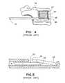
- FIG. 4shows a plan view of a further configuration of distraction device being deployed within a vertebral body, shown in sectional view.
- FIG. 5illustrates a cross-sectional view of the insertion apparatus of FIG. 3 deploying a distraction device in a manner usable with an embodiment of the present invention.
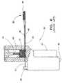
- FIG. 6shows a sectional view of an insertion apparatus usable with an embodiment of the present invention.
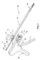
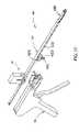
- FIG. 7is a perspective, partially exploded view of a wafer insertion apparatus in accordance with a further embodiment of the invention.
- FIG. 8is an exploded view of the advancement gun component of the wafer insertion apparatus shown in FIG. 7 .
- FIG. 9is an exploded view of the wafer cartridge component of the wafer insertion apparatus shown in FIG. 7
- FIG. 10is an enlarged view of the interface between the wafer cartridge component shown in FIG. 9 and a cartridge latch component of the wafer insertion apparatus shown in FIGS. 7 and 8 .
- FIG. 11is an enlarged side cut-away view of the wafer insertion apparatus shown in FIG. 7 .
- FIG. 12is an enlarged perspective view of the trigger and advancer carriage components of the advancement gun shown in FIG. 8 .
- FIG. 13is an exploded view of the track assembly component of the wafer insertion apparatus shown in FIG. 7 .
- FIG. 14is an exploded view of an advancer/pusher assembly for use with the wafer insertion apparatus shown in FIG. 7 .
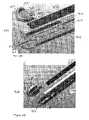
- FIGS. 15( a )– 15 ( c )are side partial views of the advancer/pusher shown in FIG. 14 mounted within the track assembly shown in FIG. 13 in different stages of operation to advance a wafer along the track assembly.
- FIGS. 16( a )–( c )are side views of the apparatus depicting various stages of advancement of a wafer to the discharge end.
- FIG. 17is perspective cut-away view of a wafer insertion apparatus according to a further embodiment of the invention.
- FIG. 18is a side cross-sectional view of the wafer cartridge portion of the apparatus shown in FIG. 17 .
- FIG. 19is a perspective cut-away view of a wafer insertion apparatus according to a further embodiment of the invention.
- FIG. 20is a side cross-sectional view of a detachable tip for a wafer inserter according to any of the prior embodiments.
- FIG. 21is a front partial perspective view of the detachable tip depicted in FIG. 20 .
- FIG. 22is a top perspective view of a detachable wafer assembly according to one embodiment of the invention.
- FIG. 23is a top exploded perspective view of the detachable wafer assembly shown in FIG. 22 .
- FIG. 24is a bottom exploded perspective view of the detachable wafer assembly shown in FIG. 22 .
- FIG. 25is a side perspective view of a bone cement delivery system according to a further embodiment of the invention.
- FIG. 26is an end perspective view of the bone cement delivery system shown in FIG. 25 .
- FIG. 27is a top perspective view of a detachable wafer assembly according to another embodiment of the invention.
- FIG. 28is a top perspective view of a detachable wafer assembly according to a further embodiment of the invention.
- FIG. 29is a bottom perspective view of the detachable wafer assembly shown in FIG. 28 .
- FIG. 30is a perspective, partially exploded view of a wafer insertion apparatus with a detachable wafer component in accordance with a further embodiment of the invention.
- FIG. 1shows a vertebral body 10 having a compression fracture displacing its superior and anterior edge 11 .
- FIG. 2shows a vertebral body 10 wherein the height has been restored.
- a plurality of stackable waferscan be provided for insertion between two tissues and can be delivered to a surgical site along an axis transverse to the axis of distraction. Multiple wafer insertions result in a column of wafers at the surgical site that simultaneously distracts and supports the two tissues.
- the wafersmay be formed from a solid form of bone filler material, and/or any other suitable material such as, but not limited to, implantable grade alloys, medical grade composites, medical grade polymers, ceramics, hydrogels and resorbable polymers.
- the wafersmay be dense or porous, while porous wafers may be filled with resorbable polymers, drug therapies or osteoinductive agents.
- FIG. 3illustrates the distal or discharge end portion 16 of a wafer insertion apparatus 15 placed within a vertebral body 10 with a wafer 18 positioned distally on the wafer insertion apparatus 15 .
- a plurality of such wafers 18is stacked to form a column to restore vertebral height, such as the column 20 depicted in FIG. 5 .
- Details of an exemplary wafer insertion apparatus 15can be found in U.S. Pat. No. 6,595,998 [the '998 Patent], entitled “Tissue Distraction Device”, which issued on Jul. 22, 2003, to the assignee of the present invention. The disclosure of this '998 Patent is incorporated herein by reference.
- the trailing edge of a wafercan be beveled or otherwise configured to guide the next wafer under the first.
- the wafer 22depicted in FIG. 5 , includes a beveled leading edge 23 .
- This beveled edge 23facilitates guiding the wafer under the trailing edge 24 of a preceding wafer 22 .
- the trailing edgeis correspondingly beveled to guide the subsequent wafer underneath.
- the wafers 22can have a variety of configurations and dimensions depending upon the particular surgical application. For instance, for vertebral compression fracture applications, exemplary wafer dimensions range as follows:
- the wafersmay be secured to one another after insertion. Any suitable method for securing the wafers to one another as known by those skilled in the arts may be used. Wafers may be secured to one another by means of an adhesive bond, a chemical bond, and/or a mechanical interlock (as described above). Applying a generic fluent adhesive, for example cyanoacrylate, into the cavity surrounding the column provides adhesive bonding. The fluent adhesive hardens and locks the wafers.
- a generic fluent adhesivefor example cyanoacrylate
- the wafersmay also include tunnels, grooves, or holes to facilitate movement of bone filler or other fluent materials through the wafer column into the surrounding bone. Further, openings may be provided through the wafers to allow communication between the tunnels, grooves, or holes or adjacent wafers. In any configuration, bone filler material injected into the wafer column would then flow through the column, fully encapsulating the wafers and better bonding the wafers to the bone filler. Further details of suitable wafers are disclosed in the '998 Patent, which details are again incorporated herein by reference.
- the wafersare inserted such that consecutive wafer insertions form a column 20 , as shown in FIG. 5 .
- the wafers in the columncan be equally sized wafers, such as the intermediate wafers 26 .
- the columncan include larger top and bottom wafers 27 , 28 , respectively, to provide a larger surface area over which to distribute loads.
- the larger waferscreate a space or channel 30 between the edges of the intermediate wafers 26 and the surrounding tissue. This channel provides a path around the interspaced wafers through which a bone filler or other fluent material may flow to fully encapsulate the wafers and to interdigitate with surrounding tissue.
- a wafer insertion apparatusis provided as part of the invention to deliver the wafers to the surgical site and to form a column of wafers.
- the wafer insertion apparatusapplies a force along the X-axis (the axis of insertion) to a wafer that is to be added to the column.
- the wafersmay be configured with beveled ends to facilitate growth of the column along the Z-axis (the vertical axis through the wafers) as the additional wafer is inserted.
- the wafer insertion apparatusis comprised of a track, which is a long narrow channel through which wafers pass when placed into the wafer column.
- a plungergenerally advances wafers down the track.
- Multiple waferscan be housed in a cartridge of the wafer insertion apparatus for advancement down the track.
- a mechanism for feeding subsequent wafers into the track in front of the plungeris configured for removal from the surgical site while leaving the wafer column intact.
- FIG. 6One embodiment of a wafer insertion apparatus 35 described in the '998 Patent is illustrated in FIG. 6 .
- the handle 36may be gripped to position the wafer insertion apparatus 35 .
- the wafer insertion apparatushas, at its proximal end 38 , a magazine 40 containing wafers 41 .
- the wafers 41may be stacked in the magazine 40 with a top surface of one wafer supporting the bottom surface of an adjacent wafer.
- the handle 36is equipped with a trigger 37 for forcing wafers out of the magazine 40 .
- the magazine 40is equipped with a spring 43 to load wafers 41 along a track 45 of the inserter 35 .
- the track 45extends from the magazine 40 to the surgical site at its distal end 46 .
- the track 45 in the wafer insert 35 shown in FIG. 6includes a lower cavity 48 and an upper cavity 49 .
- a plunger 51extends through the lower cavity 48 while the wafers 41 are aligned along the upper surface of the plunger.
- An openingis provided along the top surface of the lower cavity 48 at the distal end 46 of the track 45 to accommodate a wafer.
- a wafer insertion apparatus 60includes a wafer cartridge 61 , a track assembly 63 and an advancement gun 65 , as shown in FIGS. 7–16 .
- Details of this wafer insertion apparatuscan be found in co-pending U.S. patent application Ser. No. 10/813,819 [the '819 application], entitled “Tissue Distraction Device”, which was filed on Mar. 31, 2004, and which is assigned to the owner of the present application.
- the disclosure of this co-pending '819 applicationis incorporated herein by reference; however, for purposes of illustration certain details of this apparatus 60 will be described below.
- the advancement gun 65includes left and right housings 67 , 68 that can be coupled together in a known manner.
- the housingsare formed of a high-density plastic material that can be molded to define various interior and exterior features.
- the housingssupport a manual trigger 70 that is pivotably mounted to the housings 67 , 68 by a pivot pin 71 .
- the trigger 70includes a manual grip 72 that is accessible outside the housings, and a lever arm 73 that operates within the housing.
- the lever arm 73includes a return spring tab 74 , seen best in FIG. 11 , which provides a connection point for a return spring 76 .
- the return spring 76can be mounted within the handle 78 to apply a restorative force to the trigger 70 after it has been manually depressed and released.
- the advancement gun 65includes a wafer advancement carriage 80 that is slidably disposed within an advancer channel 90 in the housings 67 , 68 , as shown in FIG. 11 .
- the carriage 80is connected to the lever arm 73 of the trigger 70 by way of a link 82 .
- the link 82is pivotably connected to the lever arm 73 and the carriage 80 by corresponding pivot pins 84 , as depicted in FIGS. 11 and 12 .
- the lever arm 73pivots in a clockwise direction, which pushes the link 82 against the carriage 80 .
- the pivoting movement of the triggeris translated to a linear movement of the carriage 80 toward the distal end 69 of the advancement gun 65 .
- Each depression of the triggerconstitutes one cycle of operation of the advancement gun, which corresponds to moving each wafer an incremental distance toward the discharge end 64 of the track assembly 63 .
- This incremental distanceis determined by the “throw” of the advancement gun, which in turn is related to the angle through which the trigger 70 can pivot within the gun.
- the throw of the advancement guncorresponds to a distance slightly greater than the length of a wafer.
- the advancement gun 65includes means for engaging a removable wafer cartridge, such as the cartridge 61 . This feature allows a cartridge to be replaced while the apparatus is still in its operative position relative to the tissue surfaces being distracted.
- the distal end 69 of the advancement gun 65defines engagement slots 95 that interface with locking cams 102 on opposite sides of the cartridge housing 100 (see FIG. 9 ).
- the cams 102are configured to slide into the engagement slots 95 .
- the advancement gun 65includes latch halves 97 pivotably mounted to corresponding housing halves 67 , 68 by a pivot pin 98 passing through a bore 99 .
- the ends 96 of the latch halves 97are turned inward to engage an end face 102 a ( FIG. 7 ) of the locking cams 102 on cartridge 61 . When the latch ends engage the end face of the cartridge, they push the locking cams 102 into the slots 95 .
- the latch halvescan be provided with finger tabs 97 a that can be pushed or pulled to engage or release the cartridge engagement means.
- the cartridge 80is shown with a housing 100 defining a cavity for receiving a stack of wafers 101 .
- the cartridgecan be provided pre-loaded so that the cartridge can be simply engaged to the advancement gun 65 , and then removed and replaced once all the wafers have been discharged.
- the cartridge 61can include a removable retainer clip 107 that spans the cavity in the housing 100 to hold the wafer stack 101 within the cartridge until it is needed. The arms of the clip 107 pass through openings 108 in the cartridge and underneath the stack 101 . The retainer clip is kept in place as the cartridge is loaded in the advancement gun and then removed so that the stack 101 moves vertically into the gun.
- the cartridge 61includes a spring plate 104 that is mounted on top of the stack 101 .
- a spring arrangement(not shown) can be disposed between the spring plate 104 and the top of the housing 100 to provide pressure on the stack 101 .
- the spring plate 104can include a number of posts 105 configured to support the spring arrangement. The spring arrangement thus ensures that the lowermost wafer of the stack 101 is situated at the base of the cartridge during operation of the apparatus 60 .
- the wafer advancement carriage 80includes an advancer attachment notch 86 at its distal operating end.
- An attachment post 87encroaches into the notch 86 , as best seen in FIG. 12 .
- the notch 86 and post 87are provided for attaching an advancer or pusher 135 shown in FIG. 14 .
- the pusher 135includes an opening 139 at its proximal or engagement end 138 .
- the engagement end 138is configured to slide into the notch 86 of the carriage until the post 87 engages the opening 139 to lock the pusher 135 to the carriage 80 .
- the carriage 80includes an upper ratchet face 109 .
- This ratchet face 109engages a full throw assembly 110 that is configured to ensure that the carriage 80 travels through its full stroke before being allowed to return to its starting position (such as by operation of the return spring 76 connected to the trigger 70 ).
- the full throw assembly 110includes a ratchet clip 111 that engages the ratchet face 109 of the carriage as the carriage is advanced toward the distal end 69 of the advancement gun. Thus, as long as the ratchet face 109 is in contact with the clip 111 , the carriage cannot move on its return stroke.
- the carriagecan be drawn back to its initial position by the lever arm 73 and link 82 , preferably by operation of the spring 76 .
- This featureensures that the trigger will be fully depressed and a wafer advanced through a full cycle of movement. Absent this feature, a partial depression of the trigger could cause the wafer insertion apparatus to jam as a partially advanced or partially loaded wafer gets lodged within the track assembly 63 .
- the track assembly 63includes a top track 115 , a bottom track 120 and a wafer stay 125 .
- the track assembly 63is mounted to the wafer cartridge 100 , which is mounted to the distal end 69 of the advancement gun 65 .
- the end walls 61 a of the wafer cartridge housing 100define a slot 103 into which the track assembly 63 is mounted.
- the top trackincludes a wafer insertion opening 116 that is disposed immediately beneath the wafer stack 101 when the track assembly is mounted within the slot 103 .
- the top trackfurther defines a wafer channel 117 along its length that provides the initial path along which a succession of wafers can be advanced to the discharge end 64 ( FIG. 7 ) of the apparatus.
- the end 118 of the top trackis configured to engage the bottom track at a location 121 .
- the end 118is configured to wrap around the bottom track at this location and can be suitably affixed so that the track assembly 63 is substantially rigid.
- the channel 117 of the top track 115retains the wafer stay 125 , which functions to hold wafers within the channel 117 as the advancer/pusher mechanism 92 follows its return stroke (as explained below).
- a tab 127 at the proximal end of the wafer stayengages the distal end of the wafer insertion opening 116 to hold the stay in place.
- the wafer stay 125includes a series of substantially evenly spaced intermediate prongs 126 .
- the prongs 126project downward at an angle into the wafer channel 117 , facing the discharge end 64 , as illustrated in FIG. 15( a ). With this orientation, the prongs 125 do not impede forward movement of wafers along the channel.
- prongs 126 of the wafer stay 125are formed of a material that is sufficiently firm to resist this retrograde movement, yet sufficiently flexible to deflect upward as a wafer passes underneath.
- the prongs, as well as the entire wafer staymay be formed of a thin gage stainless steel.
- the bottom track 120defines a pusher channel 124 that receives the advancer/pusher mechanism 92 ( FIGS. 7 and 14 ) for reciprocating linear motion.
- the top track 115is configured to overlie the bottom track 120 and engages the bottom track at the engagement end 118 , as described above.
- the engagement end 118is configured to provide an exit opening for a wafer that has traveled the length of the top track. The wafer thus exits the top track and drops into the bottom track 120 at the introduction slot 121 .
- the wafer stay 125is configured to assist in this track change.
- the distal end of the wafer stayincludes a pair of opposite spaced apart leaf springs 128 . These leaf springs help maintain the wafer stay 125 within the top track 115 and also help keep the wafers in a proper orientation for entry into the introduction opening 121 of the bottom track, as best illustrated in FIG. 15( c ).
- the wafer stay 125also includes a dislodgement leaf spring 129 that is angled downward toward the bottom track. As a wafer moves toward the discharge/engagement end 118 , the dislodgement leaf spring 129 pushes the wafer down into the introduction opening 121 of the bottom track 120 .
- the pusherFIG. 14
- the mechanismincludes an advancer 131 that includes a series of substantially evenly spaced fingers 132 . These fingers project upward into the top track 115 when the advancer/pusher mechanism is disposed within the channel 124 in the bottom track 120 , as shown in FIG. 15( b ). Like the wafer stay 125 , the fingers 132 on the inserter 131 are angled forward. This forward sweep of the fingers allows the inserter 131 to be retracted without pulling a wafer backward with it. As with the wafer stay, the fingers 132 are preferably spaced apart a distance slightly greater than the length of a wafer. In this way, the length of the tracks can be minimized and the regularity of the wafer insertion can be maintained.
- the advancer 131includes attachment clips 133 that engage attachment slots 137 in the pusher 135 .
- the advancer 131 and pusher 135are coupled and move together within the channel 124 of the bottom track.
- the pusher 135essentially only operates on a wafer that is within the discharge opening 122 of the bottom channel.
- the pusher 135includes a pusher end 136 that is configured to engage the proximal end of a wafer.
- the opposite end of the pusherdefines an engagement end 138 and opening 139 that engage the wafer advancement carriage 80 as described above.
- FIGS. 15( a )–( c )The operation of the track assembly 63 and advancer/pusher mechanism 92 can be understood from consideration of FIGS. 15( a )–( c ).
- a wafer 22is shown within the wafer channel 117 of the top track 115 .
- the waferincludes a leading beveled end 23 that facilitates introduction of the wafer 22 underneath a previously advanced wafer disposed at the distraction site.
- the proximal end of the waferpreferably defines an advancement notch 140 that can be engaged by the wafer advancer 131 and the pusher 135 . As shown in FIGS.
- a finger 132 of the advancer 131engages the notch 23 of the wafer 22 to push it along the top track 115 toward the distraction site.
- a prong 126 of the wafer stay 125is also shown in FIG. 15( a ), wherein the prong is deflected upward to allow passage of the wafer.
- the wafer 22can be provided with a notch 142 at its leading end.
- Prongs 126 of the wafer stay 125can resiliently drop into the notch 142 as the leading end of the wafer advances to prevent retrograde movement of the wafer.
- the wafer stayincludes four prongs 126 to engage the notch 142 of three wafers situated within the wafer channel 117 .
- the prongs 126are spaced along the top track by a distance slightly greater than the length of a wafer.
- prongscan be provided, with the understanding that when the wafers sit within the wafer channel at the end of a stroke some prongs will engage the retrograde notches 142 of the wafers while other prongs will be resiliently compressed by the wafers.
- the dislodgement leaf spring 129 of the wafer stay 125contacts the wafer, as shown in FIG. 15( c ).
- the spring 129pushes the wafer downward into the bottom track 120 .
- the pusher 135is beneath the wafer.
- the end 136 of the pushercan then contact the advancement notch 23 of the wafer.
- the advancer/pusher mechanism 92is propelled toward the discharge end 64 of the apparatus, so the pusher end 136 continues to push the wafer until it is firmly positioned at the bottom of the distraction stack.
- the advancer/pusher mechanism 92(including the connected advancer 131 and pusher 135 ) moves in the pusher channel 124 of the bottom track 120 relative to the stationary wafer stay 125 , which is fixed within the wafer channel 117 of the top track 115 .
- the fingers 132 of the wafer advancer 131slide along the bottom of the wafers remaining in the wafer channel 117 until the wafer advancement carriage 80 reaches the end of its return stroke.
- the rearmost prong 132 ais situated beneath the wafer cartridge 61 .
- a wafer from the stack 101 that has fallen into the opening 116 in the top track 115is engaged by the finger 132 a.
- the carriage 80propels the advancer/pusher mechanism 92 to simultaneously propel one wafer into the wafer discharge opening 122 of the bottom track 120 and other wafers within the top track along the wafer channel 117 . This procedure is repeated until the stack of wafers has been fully formed within the distracted body.
- FIGS. 16( a )–( c )A sequence of events in the use of the insertion apparatus 60 is depicted in FIGS. 16( a )–( c ).
- a wafer 22is situated at the bottom of the wafer stack 101 within the wafer channel 117 , as shown in FIG. 16( a ).
- the advancement notch 140 of the waferis engaged by a finger 132 of the wafer advancer 131 .
- the remainder of the wafer channel 117is empty.
- the wafer advancement carriage 80is translated forward (by depressing the trigger 70 of the advancement gun 65 ), the carriage pushes the wafer advancer 131 , and ultimately the finger 132 advances the wafer along the top track 115 , as shown in FIG. 16( b ).
- the wafer advancer 131is shown near the end of its stroke in FIG. 16( b ).
- the advancerWhen the advancer has been fully advanced, the wafer 22 is caught by the first prong 126 of the wafer stay 125 .
- the advanceris then retracted with the carriage 80 until the advancer 131 is aligned under the wafer stack 101 , as depicted in FIG. 16( a ).
- the next waferhas already dropped through the opening 116 in the top track 115 and is awaiting engagement by the finger 132 .
- the above stepsare repeated and with each successive depression of the trigger the wafers 22 advance to the next prong 126 of the wafer stay.
- the initial wafer 22is in the position shown in FIG. 16( c ).
- the dislodgement prong 129directs the wafer from the wafer channel 117 in the top track 115 to the pusher channel 124 in the bottom track 120 .
- the pusher 135is retracted, the wafer is held in place within the wafer introduction slot 121 .
- the advancer/pusher mechanism 92is fully retracted, the pusher 135 engages the advancement notch 140 in the lead wafer. Subsequent activation of the gun 65 causes the pusher 135 to propel the wafer into the discharge opening 122 .
- a wafer insertion apparatus 150 shown in FIGS. 17–18includes an advancement gun 152 and a wafer cartridge supported on the underside of the gun.
- the track assembly 156is supported by the gun.
- the gunincludes a trigger 158 that reciprocates a wafer advancement carriage 160 engaged to an advancement/pusher mechanism 162 . All of these components can be configured similar to the prior embodiments, except that they are modified to advance each wafer onto the top of the stack within the body cavity.
- the track assembly 156includes a top track 164 and a bottom track 166 that are essentially the analog of the bottom track 120 and top track 115 , respectively, of the previous embodiment. Thus, each wafer exits the apparatus 150 from a discharge opening 167 in the bottom track 166 .
- the moving components of the apparatus 150can be configured similar to the like components of the previous embodiment, except that components of the apparatus 150 of FIGS. 17–18 are switched between the top and bottom tracks from those in the apparatus 60 .
- the wafer cartridge 154is mounted to the underside of the advancement gun 152 .
- each waferis fed upward into the bottom track 166 and into engagement with the advancement/pusher mechanism 162 .
- a spring plate 169is biased upward into the wafer stack by an arrangement of springs 170 . This arrangement is similar to the spring biased stack described above in connection with the apparatus 60 .
- a trigger driven advancement/pusher mechanismsuch as the mechanism 92 described above.
- the triggersuch as trigger 70
- the triggeris connected to a carriage 80 by a floating link 82 .
- Other trigger or actuation mechanismsare contemplated by the invention.
- a wafer insertion apparatus 175includes an advancement gun 176 , a bottom loaded cartridge 177 and a track assembly 178 , as shown in FIG. 19 .
- An advancement/pusher mechanism 180is engaged to a carriage 181 that is slidably disposed in the gun, in a fashion similar to the embodiments described above.
- the gunfurther includes a trigger 184 that is pivotably engaged to the gun at a pivot mount 185 .
- the carriage 181includes a rack gear 182 facing the trigger.
- the trigger 184includes a clock gear 186 that meshes with the rack gear 182 as the trigger is pivoted.
- the drive interface between the trigger and the carriageis direct, without any intermediate linkage structure.
- the trigger 184defines a stop face 188 .
- This stop facecontacts a stop wall 189 of the advancement gun 176 to prevent further pivoting of the trigger. More significantly, when the trigger can no longer pivot, the translation of the carriage 181 stops, signifying the end of the stroke of the advancement/pusher mechanism 180 . With this feature, the full throw assembly 110 ( FIG. 8 ) can be eliminated. Similarly, the back face 190 of the trigger 184 can contact a rear stop wall 191 to limit the return movement of the trigger, and therefore the carriage.
- a detachable tip wafer inserter embodimentas seen in FIG. 20 , includes a distal tip 202 of a wafer inserter 200 , which can be configured like the wafer inserter of FIG. 3 or FIG. 4 , for instance.
- the distal tip 202is detachable from the main portion 204 of the inserter.
- One advantage provided by the detachable tipis that the height of the wafer column is not altered when the wafer inserter is removed.
- the tip 202is preferably manufactured of the same material as the wafers. Thus, in a preferred embodiment, if the wafers 208 are manufactured of PMMA, the distal tip 202 of the wafer inserter 200 is manufactured of PMMA.
- the distal tip 202may be manufactured of an implant grade metal or other medical grade implantable material.
- the distal tip 202has a fixed distal shoulder 206 that holds the first wafer in place while the second wafer is inserted under the first.
- the height of the distal shoulder 206may provide a stop for one wafer, or it may provide a stop for two or more wafers. The considerations applicable to the height of the distal catch apply to the height of the distal shoulder as well.
- the aforementioned '998 Patentdiscloses a detachable tip embodiment for a wafer insertion apparatus, the description of which is also incorporated herein by reference.
- wafersare inserted until the desired height or force is attained, and then, as seen in FIG. 21 , the distal tip 202 is then released from the main portion 204 of the wafer inserter and the main portion 204 of the inserter is removed.
- the distal tipmay be press-fit onto the track or may be bonded with an appropriate adhesive. In either case, the interface is designed to support the forces generated while building a wafer column 210 , but shear when the extraction plunger is used to remove the wafer inserter.
- the distal tip 202may be keyed to interlock with the main portion 204 of the wafer inserter.
- the main portion of the insertermay interlock with the distal tip by spring-loaded hooks that are mechanically compressed when the tip is to be released.
- the hooksmay be spring-loaded in the release position and mechanically expanded to engage the distal tip.
- the detachable tipmay be press-fit onto the wafer inserter or bonded with a weak adhesive. When the wafer inserter is to be removed, a force may be applied using a longer plunger or equivalent mechanism as in the fixed tip wafer inserter to dislodge the removable tip. The track of the wafer inserter may be then removed.
- the detachable wafer assembly 300includes a bottom track 302 that can be integrated into the wafer insertion assemblies described above.
- the bottom track 120 of the track assembly 33 shown in FIG. 13can be modified in the form of the bottom track 302 shown in FIGS. 22–24 .
- the bottom track 302defines a wafer channel 304 along which successive wafers can be advanced, again in the manner disclosed above.
- the wafer channelextends to an upward facing discharge opening 306 at the distal end of the bottom track.
- the wafer channel 304is also open at its end, and specifically at an end opening 308 .
- the bottom track 302further defines a cutter channel 310 beneath the wafer channel 304 .
- the cutter channelis configured to slidably receive a slide cutter 320 , shown in FIGS. 23–24 .
- the cutter channelextends at least along the length of the bottom track adjacent the distal end thereof and terminates beneath the discharge opening 306 at the end opening 308 .
- the bottom track 302defines a base wafer recess 313 that is configured to support the base wafer 330 .
- the base wafer recess 313is situated at a level above the cutter channel 310 but below the wafer channel 304 .
- the depth of the base wafer recessis calibrated so that the top surface 332 of the base wafer 330 resides substantially at the level of the wafer channel 304 so that wafers (such as wafers 208 shown in FIG. 20 ) conveyed along the channel slide directly on top of the base wafer.
- the bottom trackalso defines top cap slots 314 along the side walls adjacent the discharge opening 306 .
- the forward and rear edges of the slots 314form chamfered ends 316 and 318 , respectively.
- the slots 314 and ends 316 , 318are configured to support and retain a top cap wafer 340 .
- the top cap waferincludes end chamfers 342 , 344 that cooperate or interlock with the corresponding chamfered ends 316 , 318 to hold the top cap wafer 340 in position above the discharge opening 306 .
- the top cap wafer 340forms an end edge 346 that corresponds to a stop end 334 of the base wafer.
- the top cap wafer 340is held on top of the discharge opening as shown in FIG. 22 .
- the top cap wafer 340is configured to release from the top cap slot 314 under pressure from a wafer (such as wafer 208 ) being advanced along the bottom track 302 underneath the top cap wafer. In other words, as a new wafer moves toward the discharge opening, it moves underneath the top cap wafer 340 , dislodging the end chamfers 342 , 344 from the chamfered slot ends 316 , 318 and moving it upward within the tissue space.
- a wafersuch as wafer 208
- the top cap wafer 340is larger in dimension and/or area than the wafers conveyed along the apparatus to be added to the wafer stack S (see FIG. 25 ).
- the top cap waferhas a width or transverse dimension W ( FIG. 23 ) that is at least larger than width of the subsequently inserted wafers.
- This larger geometrycan create a vertical space or gap G ( FIG. 26 ) along the side of the wafer stack that can be subsequently filled with a biologic material, such as bone cement, bone filler, paste, putty or similar material.
- the greater area of the top cap wafer 340can increase the overall load lifting capacity of the stack by engaging a larger area of the tissue surface to be distracted.
- the top cap wafer 340can have a width dimension W that is 1–2 mm wider than the intermediate wafers. This greater dimension can also apply to the overall length of the top cap wafer, alone or in conjunction with a greater width.
- the base wafer 330is also preferably larger in area than the intermediate wafers of the stack.
- the base waferdefines an upper support surface 332 that is sized to generally approximate the size of an intermediate wafer, such as a wafer 208 .
- the stop end 334provides an end surface against which successive wafers bear when they are advanced along the bottom track.
- the stop end 334can aid in alignment and placement of the wafers as they are added to the stack.
- the stop endcan help ensure that the wafer stack is uniform and can prevent any wafers from being askew within the stack.
- the stop end 334also helps reduce or even eliminate the reaction force from the standard wafer gun insertion or from the lift forces applied by one wafer to a prior wafer.
- a connection mechanismfor releasably connecting the base wafer to the track, and more particularly to the channel defined by the track.
- the underside, or bottom surface 336 of the base wafer 330can be seen.
- the base waferincludes a number of retention bosses 338 projecting from the bottom surface 336 . These retention bosses extend first through openings 322 , 323 , 324 in the slide cutter 320 disposed beneath the base wafer. The bosses are configured to extend into boss receptacles or bores 312 defined in the cutter channel 310 of the bottom track 302 .
- the bosses 338 and bores 312form a press-fit so that the base wafer 330 is held firmly at the discharge end of the bottom track while the intermediate wafers are being inserted into the tissue space.
- the connection mechanismincludes the bosses and bores.
- the openings 322 , 323 , 324are increasingly longer from the distal to the proximal ends of the track 302 . This feature facilitates alignment of the openings 322 – 324 with the bosses 338 and bores 312 when the detachable wafer assembly 300 is constructed. As shown in FIG. 24 , the distal ends of the slots 322 – 324 define cutting edges 325 . These cutting edges 325 are configured to sever the bosses 338 from the bottom surface 336 of the base wafer 330 . Preferably, the bosses 338 are integral with the remainder of the base wafer, and most preferably formed of the same material.
- This materialis selected so that longitudinal movement of the slide cutter 320 can readily slice through the material of the boss.
- the slide cutter 320can be retracted within the bottom track 302 , severing the bosses and freeing the base wafer 330 from the bottom track 302 .
- the bottom track 302can then be removed, leaving the base wafer behind to anchor the wafer stack, as shown in FIG. 28 .
- a material delivery system 350can be provided for use once the stack S has been disposed within a tissue space, such as the interior of a vertebral body V 2 .
- the system 350includes a reusable working channel cannula 352 that can extend through an opening O formed in the vertebral wall (which is also the same opening through which the wafers are inserted).
- a cannulated material delivery port 354is concentrically disposed within the cannula of the cannula 352 and is preferably pre-filled with the biologic material, such as bone cement C.
- a plunger 356is provided to inject the biologic material C into the space surround the wafer stack S.
- an assembly 360includes a bottom track 362 that is similar to the track 302 described above in that it includes a wafer channel 364 , a wafer discharge opening 366 and an end opening 368 .
- the bottom track 362further defines a release plate channel 370 that is substantially contiguous with and beneath the wafer channel 364 .
- the release plate channel 370terminates in a release ramp 378 and catch slot 376 within the discharge opening 366 .
- the bottom track 362also defines a base wafer recess 373 that supports a base wafer 390 .
- the base wafer 390is supported with a portion of the wafer projecting from the end of the bottom track, and specifically from the end opening 368 of the bottom track 362 .
- the base wafer 390defines a wafer support surface 392 that supports the successive stack of wafers deployed through the insertion apparatus.
- the base wafer 390also includes a stop end 394 that serves the same function as the stop end for the base wafer 330 described above.
- the base waferalso defines a retention slot 396 and retention notches 398 at opposite sides of the stop end 394 .
- the retention notchesinterlock with retention posts 374 projecting upward from the bottom track 362 adjacent the release ramp 378 .
- the retention slotis configured to receive a portion of the distal end of the release plate 380 , such as the release ramp 384 .
- the underside of the release plate 380forms a catch 382 that is configured to reside within the catch slot 376 at the base of the release ramp 378 to hold the release plate 380 in position during wafer insertion.
- the base wafer 390is held to the bottom track by the interaction of the retention slot 396 and retention notches 398 with the corresponding ramp 384 and posts 374 .
- the release plate 380is retracted toward the proximal end of the bottom track 362 .
- the catch 382travels up the release ramp 378 , pushing the ramp 384 of the release plate 380 up against the underside of the base wafer 390 .
- This movementdislodges or disassociates the base wafer 390 from the release plate 380 or more specifically releases the notches 398 from the retention posts 374 .
- the bottom track 362can then be removed without disturbing the base wafer in situ.
- a detachable wafer assembly 400includes a bottom track 402 , a release plate 420 and a base wafer 430 , as shown in FIGS. 28–29 .
- the bottom track 402defines a wafer channel 404 , terminating in an end opening 405 and a wafer discharge opening 406 .
- the bottom track 402includes a split line 408 extending longitudinally along the track from the end opening 405 .
- the split lineis configured to form a base wafer retention slot 410 and a retention notch 412 at the end opening 405 . Upstream of the slot 410 is a release plate retention notch 414 .
- the features of the split line 408are configured to interlock with corresponding features on the underside of the release plate 420 and base wafer 430 .
- the release plate 420has a bottom surface 421 that includes a release cam 422 projecting therefrom. This release cam 422 is shaped to fit snugly within the notch 414 in the split line 408 when the assembly is initially put together.
- the base wafer 430includes a linear key 436 and flared key 438 formed on its underside. These keys also fit snugly within the retention slot 410 and notch 412 to hold the base wafer in association with the bottom track 402 during initial assembly.
- the bottom trackdefines angled edges at the end openings 405 that mate with corresponding angled edges 433 of the stop end 432 of the base wafer.
- the base waferfurther forms a wafer support surface 434 that supports at least a portion of subsequent wafers stacked on top of the base wafer.
- the base wafer 430is initially engaged to the bottom track 402 when the detachable wafer assembly 400 is introduced into the tissue site. As successive wafers are introduced along the wafer channel 404 , the stop end 432 of the base wafer helps maintain the alignment of the stack.
- the release plate 420is withdrawn toward the proximal end of the bottom track. As the release plate 420 moves, the release cam 422 is dislodged from the retention notch 414 and moves upstream along the split line 408 . This movement causes the bottom track to split apart along the split line 408 , thereby widening the retention slot 410 and retention notch 412 .
- the keys 436 and 438are freed from the split line so that the base wafer can be disassociated or dislodged from the bottom track.
- the bottom trackcan then be withdrawn, leaving the base wafer and the rest of the wafer stack within the distraction site.
- the detachable wafer assemblies 300 and 400can be used with a wafer insertion apparatus, such as the apparatus 35 of FIG. 6 or the apparatus 60 of FIG. 7 .
- the bottom tracks 302 and 402 of the respective assembliescan be integrated with the discharge end, such as discharge opening 122 at the distal discharge end 64 of the apparatus 60 .
- the track 63 of the wafer insertion apparatus 60would be modified to receive the slide cutter 320 , the release plate 380 or the release plate 420 and keep it clear beneath the wafer advancement components (such as the components depicted in FIG. 13 ).
- a separate triggering mechanismis preferably provided to actuate the cutter or release plates to allow dislodgement of the detachable elements of the wafer assembly.
- a detachable wafer assembly 300is integrated with the track assembly 63 of the insertion apparatus 60 , as illustrated in FIG. 30 .
- the detachable wafer assemblyincludes a slide cutter 320 that extends from the assembly 300 into the bottom track of the track assembly 63 , as depicted in dashed lines.
- a trigger assembly 450can be mounted to the underside of the track assembly, adjacent the connection between the track assembly and the gun 65 .
- a manual trigger or lever 452is engaged by a linkage 454 to the proximal end of the slide cutter. Depressing the trigger 452 propels the slide cutter to sever the retention bosses 338 , as described above. It is understood that other actuation mechanisms are contemplated to operate the slide cutter or the release plates of the other embodiments.
- the base wafer 334 , 390 and 430provide a positive stop for intermediate wafers being advanced toward the distal end of the assembly. This positive stop ensures that the wafers are stacked in substantial vertical alignment within the body cavity, even if the wafer inserter exerts an excessive axial insertion force on a newly introduced wafer to the stack.
- the detachable base waferensures that the stack height is not altered when the wafer insertion process is completed.
- Providing a top cap wafer, such as wafer 340 and a base wafer 330 with a larger area or width than the intermediate wafersprovides additional space immediately surrounding the wafer stack for the introduction of bio-compatible materials.
- the larger dimension of the cap waferhelps “clear out” cancellous bone within the body cavity as the cap wafer is pushed upward by subsequently introduced intermediate wafers.
- Impregnating the stack with a bone cement, for instance,can strengthen the stack and maintain the distraction and support capabilities of the stack.
- the detachable components of the inventive systemare formed of a material similar to the material of the intermediate wafers.
- These detachable componentssuch as the base wafer and the top cap wafer, are thus preferably formed of a PMMA, for instance.
- the base wafer and top cap wafercan be formed with bone ingrowth channels or interstices.
- one or both of the top cap wafer and base wafercan be formed of an implant grade metal, such as stainless steel or titanium.
Landscapes
- Health & Medical Sciences (AREA)
- Surgery (AREA)
- Life Sciences & Earth Sciences (AREA)
- Medical Informatics (AREA)
- Nuclear Medicine, Radiotherapy & Molecular Imaging (AREA)
- Engineering & Computer Science (AREA)
- Biomedical Technology (AREA)
- Heart & Thoracic Surgery (AREA)
- Orthopedic Medicine & Surgery (AREA)
- Molecular Biology (AREA)
- Animal Behavior & Ethology (AREA)
- General Health & Medical Sciences (AREA)
- Public Health (AREA)
- Veterinary Medicine (AREA)
- Prostheses (AREA)
- Microscoopes, Condenser (AREA)
Abstract
Description
- Wafer length between 5 mm and 50 mm;
- Wafer width between 2 mm and 16 mm;
- Wafer thickness between 0.2 mm and 6 mm; and
- Curved wafer radii between 10 mm and 500 mm.
These dimensions are provided only as guidelines and any suitable dimensions may be used. Furthermore, the dimensions of the wafer will likely vary widely when the wafers are used in other applications, such as, for example, treating tibial plateau fractures.
Claims (29)
Priority Applications (3)
| Application Number | Priority Date | Filing Date | Title |
|---|---|---|---|
| US10/846,235US6997929B2 (en) | 2003-05-16 | 2004-05-14 | Tissue distraction device |
| US11/353,711US7674278B2 (en) | 2003-05-16 | 2006-02-13 | Tissue distraction device |
| US12/625,276US8430885B2 (en) | 2003-05-16 | 2009-11-24 | Tissue distraction device |
Applications Claiming Priority (2)
| Application Number | Priority Date | Filing Date | Title |
|---|---|---|---|
| US47101503P | 2003-05-16 | 2003-05-16 | |
| US10/846,235US6997929B2 (en) | 2003-05-16 | 2004-05-14 | Tissue distraction device |
Related Child Applications (1)
| Application Number | Title | Priority Date | Filing Date |
|---|---|---|---|
| US11/353,711DivisionUS7674278B2 (en) | 2003-05-16 | 2006-02-13 | Tissue distraction device |
Publications (2)
| Publication Number | Publication Date |
|---|---|
| US20040230198A1 US20040230198A1 (en) | 2004-11-18 |
| US6997929B2true US6997929B2 (en) | 2006-02-14 |
Family
ID=33476776
Family Applications (3)
| Application Number | Title | Priority Date | Filing Date |
|---|---|---|---|
| US10/846,235Expired - LifetimeUS6997929B2 (en) | 2003-05-16 | 2004-05-14 | Tissue distraction device |
| US11/353,711Active2026-05-12US7674278B2 (en) | 2003-05-16 | 2006-02-13 | Tissue distraction device |
| US12/625,276Expired - Fee RelatedUS8430885B2 (en) | 2003-05-16 | 2009-11-24 | Tissue distraction device |
Family Applications After (2)
| Application Number | Title | Priority Date | Filing Date |
|---|---|---|---|
| US11/353,711Active2026-05-12US7674278B2 (en) | 2003-05-16 | 2006-02-13 | Tissue distraction device |
| US12/625,276Expired - Fee RelatedUS8430885B2 (en) | 2003-05-16 | 2009-11-24 | Tissue distraction device |
Country Status (2)
| Country | Link |
|---|---|
| US (3) | US6997929B2 (en) |
| WO (1) | WO2004103152A2 (en) |
Cited By (120)
| Publication number | Priority date | Publication date | Assignee | Title |
|---|---|---|---|---|
| US20040019354A1 (en)* | 2001-03-08 | 2004-01-29 | Wes Johnson | Tissue distraction device |
| US20040126557A1 (en)* | 2000-12-07 | 2004-07-01 | Lothar Thiele | Stone composite slabs |
| US20050043585A1 (en)* | 2003-01-03 | 2005-02-24 | Arindam Datta | Reticulated elastomeric matrices, their manufacture and use in implantable devices |
| US20050273171A1 (en)* | 2003-08-05 | 2005-12-08 | Gordon Charles R | Method of inserting an expandable intervertebral implant without overdistraction |
| US20060058807A1 (en)* | 2004-08-25 | 2006-03-16 | Michael Landry | Expandable interbody fusion device |
| US20060116714A1 (en)* | 2004-11-26 | 2006-06-01 | Ivan Sepetka | Coupling and release devices and methods for their assembly and use |
| US20060155296A1 (en)* | 2005-01-07 | 2006-07-13 | Celonova Biosciences, Inc. | Three-dimensional implantable bone support |
| US20060229629A1 (en)* | 2003-05-16 | 2006-10-12 | Spine Wave, Inc. | Tissue distraction device |
| US20070055271A1 (en)* | 2005-08-16 | 2007-03-08 | Laurent Schaller | Spinal Tissue Distraction Devices |
| WO2007134199A3 (en)* | 2006-05-10 | 2008-01-10 | Biomerix Corp | Spinal implants and devices and methods for their controlled insertion |
| US20080108995A1 (en)* | 2006-11-06 | 2008-05-08 | Janet Conway | Internal bone transport |
| US20080140207A1 (en)* | 2006-12-07 | 2008-06-12 | Interventional Spine, Inc. | Intervertebral implant |
| US20080208320A1 (en)* | 2006-12-15 | 2008-08-28 | Francisca Tan-Malecki | Delivery Apparatus and Methods for Vertebrostenting |
| US20080234827A1 (en)* | 2005-08-16 | 2008-09-25 | Laurent Schaller | Devices for treating the spine |
| US20080281350A1 (en)* | 2006-12-13 | 2008-11-13 | Biomerix Corporation | Aneurysm Occlusion Devices |
| US20080300598A1 (en)* | 2007-05-31 | 2008-12-04 | Spine Wave, Inc. | Expandable Interbody Fusion Device |
| US20090005816A1 (en)* | 2007-06-26 | 2009-01-01 | Denardo Andrew J | Spinal rod, insertion device, and method of using |
| US20090281551A1 (en)* | 2008-05-07 | 2009-11-12 | George Frey | Methods and apparatus for insertion of intervertebral implants and devices therefor |
| US20090326538A1 (en)* | 2006-12-15 | 2009-12-31 | Sennett Andrew R | Devices and methods for fracture reduction |
| US20100070035A1 (en)* | 2008-09-18 | 2010-03-18 | Mayer Peter L | Intervertebral disc prosthesis and method for implanting and explanting |
| US7763077B2 (en) | 2003-12-24 | 2010-07-27 | Biomerix Corporation | Repair of spinal annular defects and annulo-nucleoplasty regeneration |
| US7785351B2 (en) | 2003-08-05 | 2010-08-31 | Flexuspine, Inc. | Artificial functional spinal implant unit system and method for use |
| US7803395B2 (en) | 2003-05-15 | 2010-09-28 | Biomerix Corporation | Reticulated elastomeric matrices, their manufacture and use in implantable devices |
| US20110015747A1 (en)* | 2008-03-07 | 2011-01-20 | Mcmanus Joshua | Expandable interbody spacer device |
| US7909869B2 (en) | 2003-08-05 | 2011-03-22 | Flexuspine, Inc. | Artificial spinal unit assemblies |
| US20110087329A1 (en)* | 2009-10-13 | 2011-04-14 | Nicholas Poulos | Lumbar implant |
| US7959677B2 (en) | 2007-01-19 | 2011-06-14 | Flexuspine, Inc. | Artificial functional spinal unit system and method for use |
| US20110184530A1 (en)* | 2004-05-17 | 2011-07-28 | Biomerix Corporation | High performance reticulated elastomeric matrix preparation, properties, reinforcement, and use in surgical devices, tissue augmentation and/or tissue repair |
| US20110190776A1 (en)* | 2009-12-18 | 2011-08-04 | Palmaz Scientific, Inc. | Interosteal and intramedullary implants and method of implanting same |
| US8118869B2 (en) | 2006-03-08 | 2012-02-21 | Flexuspine, Inc. | Dynamic interbody device |
| US8157844B2 (en) | 2007-10-22 | 2012-04-17 | Flexuspine, Inc. | Dampener system for a posterior stabilization system with a variable length elongated member |
| US8162994B2 (en) | 2007-10-22 | 2012-04-24 | Flexuspine, Inc. | Posterior stabilization system with isolated, dual dampener systems |
| US8182514B2 (en) | 2007-10-22 | 2012-05-22 | Flexuspine, Inc. | Dampener system for a posterior stabilization system with a fixed length elongated member |
| US8187330B2 (en) | 2007-10-22 | 2012-05-29 | Flexuspine, Inc. | Dampener system for a posterior stabilization system with a variable length elongated member |
| US8267965B2 (en) | 2007-10-22 | 2012-09-18 | Flexuspine, Inc. | Spinal stabilization systems with dynamic interbody devices |
| US8366773B2 (en) | 2005-08-16 | 2013-02-05 | Benvenue Medical, Inc. | Apparatus and method for treating bone |
| US8454617B2 (en) | 2005-08-16 | 2013-06-04 | Benvenue Medical, Inc. | Devices for treating the spine |
| US8480748B2 (en) | 2010-10-07 | 2013-07-09 | Nicholas Poulos | Lordotic expandable interbody implant and method |
| US8523912B2 (en) | 2007-10-22 | 2013-09-03 | Flexuspine, Inc. | Posterior stabilization systems with shared, dual dampener systems |
| US8535327B2 (en) | 2009-03-17 | 2013-09-17 | Benvenue Medical, Inc. | Delivery apparatus for use with implantable medical devices |
| US8715351B1 (en) | 2012-11-29 | 2014-05-06 | Spine Wave, Inc. | Expandable interbody fusion device with graft chambers |
| US8814873B2 (en) | 2011-06-24 | 2014-08-26 | Benvenue Medical, Inc. | Devices and methods for treating bone tissue |
| US8814937B2 (en) | 2008-09-18 | 2014-08-26 | Peter L. Mayer | Intervertebral disc prosthesis, method for assembling, method for implanting prosthesis, and method for explanting |
| US8828019B1 (en) | 2013-03-13 | 2014-09-09 | Spine Wave, Inc. | Inserter for expanding an expandable interbody fusion device |
| US8900312B2 (en) | 2013-03-12 | 2014-12-02 | Spine Wave, Inc. | Expandable interbody fusion device with graft chambers |
| US8906099B2 (en) | 2009-10-13 | 2014-12-09 | Nicholas Poulos | Expandable interbody implant and method |
| US8940051B2 (en) | 2011-03-25 | 2015-01-27 | Flexuspine, Inc. | Interbody device insertion systems and methods |
| US9078767B1 (en) | 2014-03-06 | 2015-07-14 | Spine Wave, Inc. | Expandable spinal interbody fusion device |
| US9211195B2 (en) | 2009-10-13 | 2015-12-15 | Nicholas Poulos | Expandable interbody implant and method |
| US9220554B2 (en) | 2010-02-18 | 2015-12-29 | Globus Medical, Inc. | Methods and apparatus for treating vertebral fractures |
| US9265623B2 (en) | 2014-03-06 | 2016-02-23 | Spine Wave, Inc. | Method of expanding a spinal interbody fusion device |
| US9364339B2 (en) | 2012-04-30 | 2016-06-14 | Peter L. Mayer | Unilaterally placed expansile spinal prosthesis |
| US20160193056A1 (en)* | 2012-04-05 | 2016-07-07 | Warsaw Orthopedic, Inc. | Interbody bone implant device |
| US9393126B2 (en) | 2012-04-20 | 2016-07-19 | Peter L. Mayer | Bilaterally placed disc prosthesis for spinal implant and method of bilateral placement |
| US9439783B2 (en) | 2014-03-06 | 2016-09-13 | Spine Wave, Inc. | Inserter for expanding body tissue |
| US9445921B2 (en) | 2014-03-06 | 2016-09-20 | Spine Wave, Inc. | Device for expanding and supporting body tissue |
| US9480485B2 (en) | 2006-12-15 | 2016-11-01 | Globus Medical, Inc. | Devices and methods for vertebrostenting |
| US9492288B2 (en) | 2013-02-20 | 2016-11-15 | Flexuspine, Inc. | Expandable fusion device for positioning between adjacent vertebral bodies |
| US9517144B2 (en) | 2014-04-24 | 2016-12-13 | Exactech, Inc. | Limited profile intervertebral implant with incorporated fastening mechanism |
| US9522070B2 (en) | 2013-03-07 | 2016-12-20 | Interventional Spine, Inc. | Intervertebral implant |
| US9526627B2 (en) | 2011-11-17 | 2016-12-27 | Exactech, Inc. | Expandable interbody device system and method |
| US20160374737A1 (en)* | 2015-06-29 | 2016-12-29 | DePuy Synthes Products, Inc. | Implant dispenser |
| JP2017509396A (en)* | 2014-03-06 | 2017-04-06 | スパイン・ウェーヴ・インコーポレイテッド | Inserter for expandable spinal interbody fusion device |
| US9615938B2 (en) | 2008-05-07 | 2017-04-11 | Mighty Oak Medical, Inc. | Methods and apparatus for insertion of implant material |
| US9700425B1 (en) | 2011-03-20 | 2017-07-11 | Nuvasive, Inc. | Vertebral body replacement and insertion methods |
| US9788963B2 (en) | 2003-02-14 | 2017-10-17 | DePuy Synthes Products, Inc. | In-situ formed intervertebral fusion device and method |
| US9839530B2 (en) | 2007-06-26 | 2017-12-12 | DePuy Synthes Products, Inc. | Highly lordosed fusion cage |
| US9861495B2 (en) | 2013-03-14 | 2018-01-09 | Raed M. Ali, M.D., Inc. | Lateral interbody fusion devices, systems and methods |
| US9883951B2 (en) | 2012-08-30 | 2018-02-06 | Interventional Spine, Inc. | Artificial disc |
| US9895236B2 (en) | 2010-06-24 | 2018-02-20 | DePuy Synthes Products, Inc. | Enhanced cage insertion assembly |
| US9913727B2 (en) | 2015-07-02 | 2018-03-13 | Medos International Sarl | Expandable implant |
| US9931223B2 (en) | 2008-04-05 | 2018-04-03 | DePuy Synthes Products, Inc. | Expandable intervertebral implant |
| US9980750B2 (en) | 2011-03-18 | 2018-05-29 | Raed M. Ali, M.D., Inc. | Spinal fusion devices and systems |
| US9993349B2 (en) | 2002-06-27 | 2018-06-12 | DePuy Synthes Products, Inc. | Intervertebral disc |
| US10045768B2 (en) | 2014-07-06 | 2018-08-14 | Javier Garcia-Bengochea | Methods and devices for surgical access |
| US10058433B2 (en) | 2012-07-26 | 2018-08-28 | DePuy Synthes Products, Inc. | Expandable implant |
| US10085783B2 (en) | 2013-03-14 | 2018-10-02 | Izi Medical Products, Llc | Devices and methods for treating bone tissue |
| US10179054B2 (en) | 2008-02-06 | 2019-01-15 | Jeffrey B. Kleiner | Spinal fusion cage system with inserter |
| US10195053B2 (en) | 2009-09-18 | 2019-02-05 | Spinal Surgical Strategies, Llc | Bone graft delivery system and method for using same |
| US10201355B2 (en) | 2009-02-06 | 2019-02-12 | Kleiner Intellectual Property, Llc | Angled surgical tool for removing tissue from within an intervertebral space |
| US10245159B1 (en) | 2009-09-18 | 2019-04-02 | Spinal Surgical Strategies, Llc | Bone graft delivery system and method for using same |
| US10398563B2 (en) | 2017-05-08 | 2019-09-03 | Medos International Sarl | Expandable cage |
| US10398565B2 (en) | 2014-04-24 | 2019-09-03 | Choice Spine, Llc | Limited profile intervertebral implant with incorporated fastening and locking mechanism |
| US10433977B2 (en) | 2008-01-17 | 2019-10-08 | DePuy Synthes Products, Inc. | Expandable intervertebral implant and associated method of manufacturing the same |
| US10500062B2 (en) | 2009-12-10 | 2019-12-10 | DePuy Synthes Products, Inc. | Bellows-like expandable interbody fusion cage |
| US10537436B2 (en) | 2016-11-01 | 2020-01-21 | DePuy Synthes Products, Inc. | Curved expandable cage |
| US10548741B2 (en) | 2010-06-29 | 2020-02-04 | DePuy Synthes Products, Inc. | Distractible intervertebral implant |
| US10687830B2 (en) | 2015-07-06 | 2020-06-23 | Javier Garcia-Bengochea | Methods and devices for surgical access |
| US10687962B2 (en) | 2013-03-14 | 2020-06-23 | Raed M. Ali, M.D., Inc. | Interbody fusion devices, systems and methods |
| US10888433B2 (en) | 2016-12-14 | 2021-01-12 | DePuy Synthes Products, Inc. | Intervertebral implant inserter and related methods |
| US10932793B2 (en) | 2016-01-11 | 2021-03-02 | Covidien Lp | Endoscopic reposable surgical clip applier |
| US10940016B2 (en) | 2017-07-05 | 2021-03-09 | Medos International Sarl | Expandable intervertebral fusion cage |
| US10973656B2 (en) | 2009-09-18 | 2021-04-13 | Spinal Surgical Strategies, Inc. | Bone graft delivery system and method for using same |
| US10987228B2 (en) | 2011-03-18 | 2021-04-27 | Raed M. Ali, M.D., Inc. | Devices and methods for transpedicular stabilization of the spine |
| US11065132B2 (en) | 2014-03-06 | 2021-07-20 | Spine Wave, Inc. | Method of expanding a space between opposing tissue surfaces |
| US11096799B2 (en) | 2004-11-24 | 2021-08-24 | Samy Abdou | Devices and methods for inter-vertebral orthopedic device placement |
| US11173040B2 (en) | 2012-10-22 | 2021-11-16 | Cogent Spine, LLC | Devices and methods for spinal stabilization and instrumentation |
| US11179248B2 (en) | 2018-10-02 | 2021-11-23 | Samy Abdou | Devices and methods for spinal implantation |
| US11246718B2 (en) | 2015-10-14 | 2022-02-15 | Samy Abdou | Devices and methods for vertebral stabilization |
| US11259935B1 (en) | 2016-10-25 | 2022-03-01 | Samy Abdou | Devices and methods for vertebral bone realignment |
| US11324608B2 (en) | 2011-09-23 | 2022-05-10 | Samy Abdou | Spinal fixation devices and methods of use |
| US11344424B2 (en) | 2017-06-14 | 2022-05-31 | Medos International Sarl | Expandable intervertebral implant and related methods |
| US11395626B2 (en) | 2006-12-07 | 2022-07-26 | DePuy Synthes Products, Inc. | Sensor for intervertebral fusion indicia |
| US11426286B2 (en) | 2020-03-06 | 2022-08-30 | Eit Emerging Implant Technologies Gmbh | Expandable intervertebral implant |
| US11426290B2 (en) | 2015-03-06 | 2022-08-30 | DePuy Synthes Products, Inc. | Expandable intervertebral implant, system, kit and method |
| US11446156B2 (en) | 2018-10-25 | 2022-09-20 | Medos International Sarl | Expandable intervertebral implant, inserter instrument, and related methods |
| US11452607B2 (en) | 2010-10-11 | 2022-09-27 | DePuy Synthes Products, Inc. | Expandable interspinous process spacer implant |
| US11510788B2 (en) | 2016-06-28 | 2022-11-29 | Eit Emerging Implant Technologies Gmbh | Expandable, angularly adjustable intervertebral cages |
| US11559336B2 (en) | 2012-08-28 | 2023-01-24 | Samy Abdou | Spinal fixation devices and methods of use |
| US11596523B2 (en) | 2016-06-28 | 2023-03-07 | Eit Emerging Implant Technologies Gmbh | Expandable and angularly adjustable articulating intervertebral cages |
| US11612491B2 (en) | 2009-03-30 | 2023-03-28 | DePuy Synthes Products, Inc. | Zero profile spinal fusion cage |
| US11666455B2 (en) | 2009-09-18 | 2023-06-06 | Spinal Surgical Strategies, Inc., A Nevada Corporation | Bone graft delivery devices, systems and kits |
| US11752009B2 (en) | 2021-04-06 | 2023-09-12 | Medos International Sarl | Expandable intervertebral fusion cage |
| US11839413B2 (en) | 2012-02-22 | 2023-12-12 | Samy Abdou | Spinous process fixation devices and methods of use |
| US11850160B2 (en) | 2021-03-26 | 2023-12-26 | Medos International Sarl | Expandable lordotic intervertebral fusion cage |
| US11911287B2 (en) | 2010-06-24 | 2024-02-27 | DePuy Synthes Products, Inc. | Lateral spondylolisthesis reduction cage |
| US11918486B2 (en) | 2009-12-07 | 2024-03-05 | Samy Abdou | Devices and methods for minimally invasive spinal stabilization and instrumentation |
| USRE49973E1 (en) | 2013-02-28 | 2024-05-21 | DePuy Synthes Products, Inc. | Expandable intervertebral implant, system, kit and method |
| US12090064B2 (en) | 2022-03-01 | 2024-09-17 | Medos International Sarl | Stabilization members for expandable intervertebral implants, and related systems and methods |
| US12440346B2 (en) | 2023-03-31 | 2025-10-14 | DePuy Synthes Products, Inc. | Expandable intervertebral implant |
Families Citing this family (34)
| Publication number | Priority date | Publication date | Assignee | Title |
|---|---|---|---|---|
| DE60139262D1 (en) | 2000-08-28 | 2009-08-27 | Disc Dynamics Inc | SYSTEM FOR RECONSTRUCTING JOINT SURFACES OF MAMMALS |
| US7267690B2 (en) | 2005-03-09 | 2007-09-11 | Vertebral Technologies, Inc. | Interlocked modular disc nucleus prosthesis |
| CA2603400C (en)* | 2005-04-01 | 2015-11-24 | Ibalance Medical, Inc. | Method and apparatus for performing an open wedge, high tibial osteotomy |
| US20060282042A1 (en)* | 2005-06-08 | 2006-12-14 | Sensors For Medicine And Science, Inc. | Insertion device and method |
| US9737414B2 (en) | 2006-11-21 | 2017-08-22 | Vertebral Technologies, Inc. | Methods and apparatus for minimally invasive modular interbody fusion devices |
| US8387849B2 (en) | 2008-04-11 | 2013-03-05 | Ryan K. Buesseler | Fastener deployment system and method |
| EP2303196B1 (en) | 2008-07-23 | 2018-10-24 | Marc I. Malberg | Modular nucleus pulposus prosthesis |
| US9364338B2 (en) | 2008-07-23 | 2016-06-14 | Resspond Spinal Systems | Modular nucleus pulposus prosthesis |
| US8465502B2 (en) | 2008-08-25 | 2013-06-18 | Covidien Lp | Surgical clip applier and method of assembly |
| US9358015B2 (en) | 2008-08-29 | 2016-06-07 | Covidien Lp | Endoscopic surgical clip applier with wedge plate |
| WO2011098989A1 (en)* | 2010-02-15 | 2011-08-18 | Nonlinear Technologies Ltd. | Expanding conduits |
| US8403945B2 (en) | 2010-02-25 | 2013-03-26 | Covidien Lp | Articulating endoscopic surgical clip applier |
| WO2011150350A1 (en)* | 2010-05-28 | 2011-12-01 | Benvenue Medical, Inc. | Disc space sizing devices and methods of using the same |
| US9144501B1 (en) | 2010-07-16 | 2015-09-29 | Nuvasive, Inc. | Fracture reduction device and methods |
| US8968337B2 (en) | 2010-07-28 | 2015-03-03 | Covidien Lp | Articulating clip applier |
| WO2013036707A1 (en) | 2011-09-09 | 2013-03-14 | Spine Wave, Inc. | Lateral approach expandable spinal implant and method |
| US20130178940A1 (en)* | 2012-01-06 | 2013-07-11 | Thompson Mis | Expandable cage spinal implant |
| US9510953B2 (en) | 2012-03-16 | 2016-12-06 | Vertebral Technologies, Inc. | Modular segmented disc nucleus implant |
| US9480574B2 (en) | 2013-03-14 | 2016-11-01 | Benvenue Medical, Inc. | Spinal fusion implants and devices and methods for deploying such implants |
| EP3113725A4 (en)* | 2014-03-06 | 2018-04-04 | Spine Wave, Inc. | Expandable spinal interbody fusion device |
| US11246583B2 (en)* | 2014-06-18 | 2022-02-15 | Boston Scientific Scimed, Inc. | Insertion devices, anchors, and methods for securing an implant |
| US10314605B2 (en) | 2014-07-08 | 2019-06-11 | Benvenue Medical, Inc. | Apparatus and methods for disrupting intervertebral disc tissue |
| US10022243B2 (en) | 2015-02-06 | 2018-07-17 | Benvenue Medical, Inc. | Graft material injector system and method |
| CA2958160A1 (en) | 2016-02-24 | 2017-08-24 | Covidien Lp | Endoscopic reposable surgical clip applier |
| US10492795B2 (en) | 2016-11-01 | 2019-12-03 | Covidien Lp | Endoscopic surgical clip applier |
| US11583291B2 (en) | 2017-02-23 | 2023-02-21 | Covidien Lp | Endoscopic surgical clip applier |
| US10758286B2 (en) | 2017-03-22 | 2020-09-01 | Benvenue Medical, Inc. | Minimal impact access system to disc space |
| US10675043B2 (en) | 2017-05-04 | 2020-06-09 | Covidien Lp | Reposable multi-fire surgical clip applier |
| US11376015B2 (en) | 2017-11-03 | 2022-07-05 | Covidien Lp | Endoscopic surgical clip applier and handle assemblies for use therewith |
| WO2019148083A1 (en) | 2018-01-29 | 2019-08-01 | Benvenue Medical, Inc. | Minimally invasive interbody fusion |
| WO2019178575A1 (en) | 2018-03-16 | 2019-09-19 | Benvenue Medical, Inc. | Articulated instrumentation and methods of using the same |
| US11779340B2 (en) | 2020-01-02 | 2023-10-10 | Covidien Lp | Ligation clip loading device |
| US12114866B2 (en) | 2020-03-26 | 2024-10-15 | Covidien Lp | Interoperative clip loading device |
| US20230121067A1 (en)* | 2021-10-15 | 2023-04-20 | Howmedica Osteonics Corp. | Pistol Grip Joint Tensioner |
Citations (10)
| Publication number | Priority date | Publication date | Assignee | Title |
|---|---|---|---|---|
| US3486505A (en)* | 1967-05-22 | 1969-12-30 | Gordon M Morrison | Orthopedic surgical instrument |
| US5192327A (en)* | 1991-03-22 | 1993-03-09 | Brantigan John W | Surgical prosthetic implant for vertebrae |
| US5571109A (en)* | 1993-08-26 | 1996-11-05 | Man Ceramics Gmbh | System for the immobilization of vertebrae |
| US6159211A (en)* | 1998-10-22 | 2000-12-12 | Depuy Acromed, Inc. | Stackable cage system for corpectomy/vertebrectomy |
| US6478800B1 (en)* | 2000-05-08 | 2002-11-12 | Depuy Acromed, Inc. | Medical installation tool |
| US6562074B2 (en) | 2001-10-17 | 2003-05-13 | Medicinelodge, Inc. | Adjustable bone fusion implant and method |
| US6595998B2 (en)* | 2001-03-08 | 2003-07-22 | Spinewave, Inc. | Tissue distraction device |
| US20030171812A1 (en)* | 2001-12-31 | 2003-09-11 | Ilan Grunberg | Minimally invasive modular support implant device and method |
| US6656178B1 (en)* | 1999-07-28 | 2003-12-02 | Baat B.V. Engineering | Vertebral-column fusion devices and surgical methods |
| US6837904B2 (en)* | 2001-07-16 | 2005-01-04 | Spinecore, Inc. | Method of surgically treating scoliosis |
Family Cites Families (57)
| Publication number | Priority date | Publication date | Assignee | Title |
|---|---|---|---|---|
| US4524766A (en) | 1982-01-07 | 1985-06-25 | Petersen Thomas D | Surgical knee alignment method and system |
| US4683476A (en) | 1984-06-22 | 1987-07-28 | Benson S.A. | Drawing machine having automatically replaced writing members and apparatus therefor |
| US4736738A (en) | 1984-07-09 | 1988-04-12 | Matej Lipovsek | Instrument kit and procedure for performing posterior lumbar interbody fusion |
| US4888024A (en) | 1985-11-08 | 1989-12-19 | Powlan Roy Y | Prosthetic device and method of fixation within the medullary cavity of bones |
| JPS6346596A (en) | 1986-08-14 | 1988-02-27 | ニツタン株式会社 | Fire alarm equipment |
| GB8620937D0 (en) | 1986-08-29 | 1986-10-08 | Shepperd J A N | Spinal implant |
| US5484437A (en) | 1988-06-13 | 1996-01-16 | Michelson; Gary K. | Apparatus and method of inserting spinal implants |
| CA1333209C (en) | 1988-06-28 | 1994-11-29 | Gary Karlin Michelson | Artificial spinal fusion implants |
| FR2639823A1 (en) | 1988-12-06 | 1990-06-08 | Garcia Alain | Replacement of the nucleus of the intervertebral disc by a polyurethane polymerised in situ |
| US5290558A (en) | 1989-09-21 | 1994-03-01 | Osteotech, Inc. | Flowable demineralized bone powder composition and its use in bone repair |
| US5059193A (en) | 1989-11-20 | 1991-10-22 | Spine-Tech, Inc. | Expandable spinal implant and surgical method |
| US5197971A (en) | 1990-03-02 | 1993-03-30 | Bonutti Peter M | Arthroscopic retractor and method of using the same |
| US5192326A (en) | 1990-12-21 | 1993-03-09 | Pfizer Hospital Products Group, Inc. | Hydrogel bead intervertebral disc nucleus |
| EP0621020A1 (en) | 1993-04-21 | 1994-10-26 | SULZER Medizinaltechnik AG | Intervertebral prosthesis and method of implanting such a prosthesis |
| US5514180A (en) | 1994-01-14 | 1996-05-07 | Heggeness; Michael H. | Prosthetic intervertebral devices |
| ATE361028T1 (en) | 1994-01-26 | 2007-05-15 | Kyphon Inc | IMPROVED INFLATABLE DEVICE FOR USE IN SURGICAL METHODS OF FIXATION OF BONE |
| US5431658A (en) | 1994-02-14 | 1995-07-11 | Moskovich; Ronald | Facilitator for vertebrae grafts and prostheses |
| FR2719763B1 (en) | 1994-05-11 | 1996-09-27 | Jean Taylor | Vertebral implant. |
| US5980522A (en) | 1994-07-22 | 1999-11-09 | Koros; Tibor | Expandable spinal implants |
| FR2722980B1 (en) | 1994-07-26 | 1996-09-27 | Samani Jacques | INTERTEPINOUS VERTEBRAL IMPLANT |
| US5591235A (en) | 1995-03-15 | 1997-01-07 | Kuslich; Stephen D. | Spinal fixation device |
| DE19523759A1 (en) | 1995-06-29 | 1997-01-02 | Friedhelm Stecher | Flat gasket and process for its manufacture |
| US5741261A (en) | 1996-06-25 | 1998-04-21 | Sdgi Holdings, Inc. | Minimally invasive spinal surgical methods and instruments |
| US5756127A (en) | 1996-10-29 | 1998-05-26 | Wright Medical Technology, Inc. | Implantable bioresorbable string of calcium sulfate beads |
| US6190414B1 (en) | 1996-10-31 | 2001-02-20 | Surgical Dynamics Inc. | Apparatus for fusion of adjacent bone structures |
| US5860977A (en) | 1997-01-02 | 1999-01-19 | Saint Francis Medical Technologies, Llc | Spine distraction implant and method |
| US5836948A (en) | 1997-01-02 | 1998-11-17 | Saint Francis Medical Technologies, Llc | Spine distraction implant and method |
| US6045579A (en) | 1997-05-01 | 2000-04-04 | Spinal Concepts, Inc. | Adjustable height fusion device |
| CA2328229C (en) | 1997-07-09 | 2007-04-17 | Tegementa, L.L.C. | Interbody device and method for treatment of osteoporotic vertebral collapse |
| US6852095B1 (en) | 1997-07-09 | 2005-02-08 | Charles D. Ray | Interbody device and method for treatment of osteoporotic vertebral collapse |
| US5951553A (en) | 1997-07-14 | 1999-09-14 | Sdgi Holdings, Inc. | Methods and apparatus for fusionless treatment of spinal deformities |
| US6287308B1 (en) | 1997-07-14 | 2001-09-11 | Sdgi Holdings, Inc. | Methods and apparatus for fusionless treatment of spinal deformities |
| US6241771B1 (en) | 1997-08-13 | 2001-06-05 | Cambridge Scientific, Inc. | Resorbable interbody spinal fusion devices |
| FR2768609B1 (en) | 1997-09-23 | 2000-01-14 | Dimso Sa | SCREW AND PLATE SYSTEM FOR OSTEOSYNTHESIS OF THE RACHIS |
| US6033411A (en) | 1997-10-14 | 2000-03-07 | Parallax Medical Inc. | Precision depth guided instruments for use in vertebroplasty |
| GB9804473D0 (en) | 1998-03-02 | 1998-04-29 | Benoist Girard & Cie | Prosthesis inserter |
| BR9805340B1 (en) | 1998-12-14 | 2009-01-13 | variable expansion insert for spinal stabilization. | |
| US6159244A (en) | 1999-07-30 | 2000-12-12 | Suddaby; Loubert | Expandable variable angle intervertebral fusion implant |
| US6200347B1 (en) | 1999-01-05 | 2001-03-13 | Lifenet | Composite bone graft, method of making and using same |
| US6110210A (en) | 1999-04-08 | 2000-08-29 | Raymedica, Inc. | Prosthetic spinal disc nucleus having selectively coupled bodies |
| AU4246000A (en) | 1999-04-16 | 2000-11-02 | Nuvasive, Inc. | Articulation systems for positioning minimally invasive surgical tools |
| US6419705B1 (en) | 1999-06-23 | 2002-07-16 | Sulzer Spine-Tech Inc. | Expandable fusion device and method |
| AU5701200A (en) | 1999-07-02 | 2001-01-22 | Petrus Besselink | Reinforced expandable cage |
| CA2287112C (en) | 1999-09-02 | 2008-02-19 | Kieran Murphy | Method and apparatus for strengthening vertebral bodies |
| EP1792586B1 (en) | 1999-09-14 | 2012-12-26 | Spine Solutions Inc. | Insert instrument for an implant between vertebrae |
| US6432107B1 (en) | 2000-01-15 | 2002-08-13 | Bret A. Ferree | Enhanced surface area spinal fusion devices |
| US6395034B1 (en) | 1999-11-24 | 2002-05-28 | Loubert Suddaby | Intervertebral disc prosthesis |
| US6500205B1 (en) | 2000-04-19 | 2002-12-31 | Gary K. Michelson | Expandable threaded arcuate interbody spinal fusion implant with cylindrical configuration during insertion |
| US6740093B2 (en) | 2000-02-28 | 2004-05-25 | Stephen Hochschuler | Method and apparatus for treating a vertebral body |
| US6402750B1 (en) | 2000-04-04 | 2002-06-11 | Spinlabs, Llc | Devices and methods for the treatment of spinal disorders |
| AU5326701A (en) | 2000-04-05 | 2001-10-23 | Kyphon Inc | Methods and devices for treating fractured and/or diseased bone |
| CN101543422B (en) | 2000-04-07 | 2012-07-04 | 科丰有限公司 | System for determining the expansion direction of an expandable structure within a bone |
| US6852126B2 (en) | 2000-07-17 | 2005-02-08 | Nuvasive, Inc. | Stackable interlocking intervertebral support system |
| US6620196B1 (en) | 2000-08-30 | 2003-09-16 | Sdgi Holdings, Inc. | Intervertebral disc nucleus implants and methods |
| DE60224850T2 (en) | 2001-02-04 | 2009-01-22 | Warsaw Orthopedic, Inc., Warsaw | Instrumentation for introducing and positioning an expandable intervertebral fusion implant |
| US20020147496A1 (en) | 2001-04-06 | 2002-10-10 | Integrated Vascular Systems, Inc. | Apparatus for treating spinal discs |
| WO2004103152A2 (en) | 2003-05-16 | 2004-12-02 | Spine Wave, Inc. | Tissue distraction device |
- 2004
- 2004-05-14WOPCT/US2004/015092patent/WO2004103152A2/enactiveSearch and Examination
- 2004-05-14USUS10/846,235patent/US6997929B2/ennot_activeExpired - Lifetime
- 2006
- 2006-02-13USUS11/353,711patent/US7674278B2/enactiveActive
- 2009
- 2009-11-24USUS12/625,276patent/US8430885B2/ennot_activeExpired - Fee Related
Patent Citations (16)
| Publication number | Priority date | Publication date | Assignee | Title |
|---|---|---|---|---|
| US3486505A (en)* | 1967-05-22 | 1969-12-30 | Gordon M Morrison | Orthopedic surgical instrument |
| US5192327A (en)* | 1991-03-22 | 1993-03-09 | Brantigan John W | Surgical prosthetic implant for vertebrae |
| US5571109A (en)* | 1993-08-26 | 1996-11-05 | Man Ceramics Gmbh | System for the immobilization of vertebrae |
| US6159211A (en)* | 1998-10-22 | 2000-12-12 | Depuy Acromed, Inc. | Stackable cage system for corpectomy/vertebrectomy |
| US6656178B1 (en)* | 1999-07-28 | 2003-12-02 | Baat B.V. Engineering | Vertebral-column fusion devices and surgical methods |
| US6478800B1 (en)* | 2000-05-08 | 2002-11-12 | Depuy Acromed, Inc. | Medical installation tool |
| US20040220580A1 (en)* | 2001-03-08 | 2004-11-04 | Wes Johnson | Tissue distraction device |
| US6595998B2 (en)* | 2001-03-08 | 2003-07-22 | Spinewave, Inc. | Tissue distraction device |
| US20040019354A1 (en)* | 2001-03-08 | 2004-01-29 | Wes Johnson | Tissue distraction device |
| US20040064144A1 (en)* | 2001-03-08 | 2004-04-01 | Wes Johnson | Tissue distraction device |
| US6837904B2 (en)* | 2001-07-16 | 2005-01-04 | Spinecore, Inc. | Method of surgically treating scoliosis |
| US6648917B2 (en) | 2001-10-17 | 2003-11-18 | Medicinelodge, Inc. | Adjustable bone fusion implant and method |
| US6562074B2 (en) | 2001-10-17 | 2003-05-13 | Medicinelodge, Inc. | Adjustable bone fusion implant and method |
| US6852129B2 (en) | 2001-10-17 | 2005-02-08 | Movdice Holding, Inc. | Adjustable bone fusion implant and method |
| US6863673B2 (en) | 2001-10-17 | 2005-03-08 | Movdice Holding, Inc. | Methods for adjustable bone fusion implants |
| US20030171812A1 (en)* | 2001-12-31 | 2003-09-11 | Ilan Grunberg | Minimally invasive modular support implant device and method |
Cited By (340)
| Publication number | Priority date | Publication date | Assignee | Title |
|---|---|---|---|---|
| US20040126557A1 (en)* | 2000-12-07 | 2004-07-01 | Lothar Thiele | Stone composite slabs |
| US7749255B2 (en) | 2001-03-08 | 2010-07-06 | Spine Wave, Inc. | Method for fusing adjacent bones |
| US9655743B2 (en) | 2001-03-08 | 2017-05-23 | Spine Wave, Inc. | Expandable interbody fusion device |
| US20090171393A9 (en)* | 2001-03-08 | 2009-07-02 | Spine Wave, Inc. | Tissue Distraction Device |
| US20050171552A1 (en)* | 2001-03-08 | 2005-08-04 | Wes Johnson | Tissue distraction device |
| US8206398B2 (en) | 2001-03-08 | 2012-06-26 | Spine Wave, Inc. | Apparatus for spinal fusion |
| US8337531B2 (en) | 2001-03-08 | 2012-12-25 | Spine Wave, Inc. | Method of supporting and distracting opposing vertebral bodies of a spine |
| US8343193B2 (en) | 2001-03-08 | 2013-01-01 | Spine Wave, Inc. | Method of supporting and distracting opposing vertebral bodies |
| US8535353B2 (en) | 2001-03-08 | 2013-09-17 | Spine Wave, Inc. | Method of providing spinal interbody fusion |
| US8123755B2 (en) | 2001-03-08 | 2012-02-28 | Spine Wave, Inc. | Tissue distraction device |
| US8075623B2 (en) | 2001-03-08 | 2011-12-13 | Spine Wave, Inc. | Apparatus and kit for distraction of tissue surfaces |
| US8974464B2 (en) | 2001-03-08 | 2015-03-10 | Spine Wave, Inc. | Expansion member for insertion into a body tissue space |
| US20060161166A1 (en)* | 2001-03-08 | 2006-07-20 | Spine Wave, Inc. | Tissue distraction device |
| US20040019354A1 (en)* | 2001-03-08 | 2004-01-29 | Wes Johnson | Tissue distraction device |
| US7153305B2 (en)* | 2001-03-08 | 2006-12-26 | Spine Wave, Inc. | Method for treating tibial plateau compression fractures |
| US9545318B2 (en) | 2001-03-08 | 2017-01-17 | Spine Wave, Inc. | Expandable interbody fusion device |
| US20090182339A1 (en)* | 2001-03-08 | 2009-07-16 | Spine Wave, Inc. | Tissue Distraction Device |
| US7905885B2 (en) | 2001-03-08 | 2011-03-15 | Spine Wave, Inc. | Reduction system for restoration of a vertebral body |
| US7811331B2 (en) | 2001-03-08 | 2010-10-12 | Spine Wave, Inc. | Tissue distraction device |
| US20070179612A1 (en)* | 2001-03-08 | 2007-08-02 | Spine Wave, Inc. | Tissue Distraction Device |
| US7799034B2 (en) | 2001-03-08 | 2010-09-21 | Spine Wave, Inc. | Tissue distraction device |
| US20080027454A1 (en)* | 2001-03-08 | 2008-01-31 | Spine Wave, Inc. | Tissue Distraction Device |
| US20080027437A1 (en)* | 2001-03-08 | 2008-01-31 | Spine Wave, Inc. | Tissue Distraction Device |
| US20080027453A1 (en)* | 2001-03-08 | 2008-01-31 | Spine Wave, Inc. | Tissue Distraction Device |
| US7780734B2 (en) | 2001-03-08 | 2010-08-24 | Spine Wave, Inc. | Tissue distraction device |
| US7780707B2 (en) | 2001-03-08 | 2010-08-24 | Spine Wave, Inc. | Method for reducing a vertebra using stacked elements |
| US20040064144A1 (en)* | 2001-03-08 | 2004-04-01 | Wes Johnson | Tissue distraction device |
| US7744637B2 (en) | 2001-03-08 | 2010-06-29 | Spine Wave, Inc. | Method for restoring vertebral body height |
| US9913731B2 (en) | 2001-03-08 | 2018-03-13 | Spine Wave, Inc. | Expandable interbody fusion device |
| US20090234361A9 (en)* | 2001-03-08 | 2009-09-17 | Spine Wave, Inc. | Tissue Distraction Device |
| US10335290B2 (en) | 2001-03-08 | 2019-07-02 | Spine Wave, Inc. | Expandable interbody fusion device |
| US9993349B2 (en) | 2002-06-27 | 2018-06-12 | DePuy Synthes Products, Inc. | Intervertebral disc |
| US20050043585A1 (en)* | 2003-01-03 | 2005-02-24 | Arindam Datta | Reticulated elastomeric matrices, their manufacture and use in implantable devices |
| US11432938B2 (en) | 2003-02-14 | 2022-09-06 | DePuy Synthes Products, Inc. | In-situ intervertebral fusion device and method |
| US11096794B2 (en) | 2003-02-14 | 2021-08-24 | DePuy Synthes Products, Inc. | In-situ formed intervertebral fusion device and method |
| US10420651B2 (en) | 2003-02-14 | 2019-09-24 | DePuy Synthes Products, Inc. | In-situ formed intervertebral fusion device and method |
| US10376372B2 (en) | 2003-02-14 | 2019-08-13 | DePuy Synthes Products, Inc. | In-situ formed intervertebral fusion device and method |
| US10433971B2 (en) | 2003-02-14 | 2019-10-08 | DePuy Synthes Products, Inc. | In-situ formed intervertebral fusion device and method |
| US10405986B2 (en) | 2003-02-14 | 2019-09-10 | DePuy Synthes Products, Inc. | In-situ formed intervertebral fusion device and method |
| US10085843B2 (en) | 2003-02-14 | 2018-10-02 | DePuy Synthes Products, Inc. | In-situ formed intervertebral fusion device and method |
| US10492918B2 (en) | 2003-02-14 | 2019-12-03 | DePuy Synthes Products, Inc. | In-situ formed intervertebral fusion device and method |
| US9925060B2 (en) | 2003-02-14 | 2018-03-27 | DePuy Synthes Products, Inc. | In-situ formed intervertebral fusion device and method |
| US9801729B2 (en) | 2003-02-14 | 2017-10-31 | DePuy Synthes Products, Inc. | In-situ formed intervertebral fusion device and method |
| US10555817B2 (en) | 2003-02-14 | 2020-02-11 | DePuy Synthes Products, Inc. | In-situ formed intervertebral fusion device and method |
| US9814589B2 (en) | 2003-02-14 | 2017-11-14 | DePuy Synthes Products, Inc. | In-situ formed intervertebral fusion device and method |
| US9814590B2 (en) | 2003-02-14 | 2017-11-14 | DePuy Synthes Products, Inc. | In-situ formed intervertebral fusion device and method |
| US10575959B2 (en) | 2003-02-14 | 2020-03-03 | DePuy Synthes Products, Inc. | In-situ formed intervertebral fusion device and method |
| US10583013B2 (en) | 2003-02-14 | 2020-03-10 | DePuy Synthes Products, Inc. | In-situ formed intervertebral fusion device and method |
| US11207187B2 (en) | 2003-02-14 | 2021-12-28 | DePuy Synthes Products, Inc. | In-situ formed intervertebral fusion device and method |
| US10786361B2 (en) | 2003-02-14 | 2020-09-29 | DePuy Synthes Products, Inc. | In-situ formed intervertebral fusion device and method |
| US9808351B2 (en) | 2003-02-14 | 2017-11-07 | DePuy Synthes Products, Inc. | In-situ formed intervertebral fusion device and method |
| US9788963B2 (en) | 2003-02-14 | 2017-10-17 | DePuy Synthes Products, Inc. | In-situ formed intervertebral fusion device and method |
| US10639164B2 (en) | 2003-02-14 | 2020-05-05 | DePuy Synthes Products, Inc. | In-situ formed intervertebral fusion device and method |
| US7803395B2 (en) | 2003-05-15 | 2010-09-28 | Biomerix Corporation | Reticulated elastomeric matrices, their manufacture and use in implantable devices |
| US20060229629A1 (en)* | 2003-05-16 | 2006-10-12 | Spine Wave, Inc. | Tissue distraction device |
| US7674278B2 (en) | 2003-05-16 | 2010-03-09 | Spine Wave, Inc. | Tissue distraction device |
| US8647386B2 (en) | 2003-08-05 | 2014-02-11 | Charles R. Gordon | Expandable intervertebral implant system and method |
| US8603168B2 (en) | 2003-08-05 | 2013-12-10 | Flexuspine, Inc. | Artificial functional spinal unit system and method for use |
| US7799082B2 (en) | 2003-08-05 | 2010-09-21 | Flexuspine, Inc. | Artificial functional spinal unit system and method for use |
| US7785351B2 (en) | 2003-08-05 | 2010-08-31 | Flexuspine, Inc. | Artificial functional spinal implant unit system and method for use |
| US20050273171A1 (en)* | 2003-08-05 | 2005-12-08 | Gordon Charles R | Method of inserting an expandable intervertebral implant without overdistraction |
| US8052723B2 (en) | 2003-08-05 | 2011-11-08 | Flexuspine Inc. | Dynamic posterior stabilization systems and methods of use |
| US7753958B2 (en) | 2003-08-05 | 2010-07-13 | Gordon Charles R | Expandable intervertebral implant |
| US20050273173A1 (en)* | 2003-08-05 | 2005-12-08 | Gordon Charles R | Expandable articulating intervertebral implant with cam |
| US7909869B2 (en) | 2003-08-05 | 2011-03-22 | Flexuspine, Inc. | Artificial spinal unit assemblies |
| US20050283244A1 (en)* | 2003-08-05 | 2005-12-22 | Gordon Charles R | Method of insertion of an expandable intervertebral implant |
| US8172903B2 (en) | 2003-08-05 | 2012-05-08 | Gordon Charles R | Expandable intervertebral implant with spacer |
| US8753398B2 (en) | 2003-08-05 | 2014-06-17 | Charles R. Gordon | Method of inserting an expandable intervertebral implant without overdistraction |
| US9579124B2 (en) | 2003-08-05 | 2017-02-28 | Flexuspine, Inc. | Expandable articulating intervertebral implant with limited articulation |
| US8257440B2 (en) | 2003-08-05 | 2012-09-04 | Gordon Charles R | Method of insertion of an expandable intervertebral implant |
| US7708778B2 (en) | 2003-08-05 | 2010-05-04 | Flexuspine, Inc. | Expandable articulating intervertebral implant with cam |
| US8147550B2 (en) | 2003-08-05 | 2012-04-03 | Flexuspine, Inc. | Expandable articulating intervertebral implant with limited articulation |
| US8123810B2 (en) | 2003-08-05 | 2012-02-28 | Gordon Charles R | Expandable intervertebral implant with wedged expansion member |
| US7794480B2 (en) | 2003-08-05 | 2010-09-14 | Flexuspine, Inc. | Artificial functional spinal unit system and method for use |
| US8118870B2 (en) | 2003-08-05 | 2012-02-21 | Flexuspine, Inc. | Expandable articulating intervertebral implant with spacer |
| US8118871B2 (en) | 2003-08-05 | 2012-02-21 | Flexuspine, Inc. | Expandable articulating intervertebral implant |
| US7763077B2 (en) | 2003-12-24 | 2010-07-27 | Biomerix Corporation | Repair of spinal annular defects and annulo-nucleoplasty regeneration |
| US20110184530A1 (en)* | 2004-05-17 | 2011-07-28 | Biomerix Corporation | High performance reticulated elastomeric matrix preparation, properties, reinforcement, and use in surgical devices, tissue augmentation and/or tissue repair |
| US20060058880A1 (en)* | 2004-08-25 | 2006-03-16 | Steve Wysocki | Expandable interbody fusion device |
| US9192484B2 (en) | 2004-08-25 | 2015-11-24 | Spine Wave, Inc. | Expandable interbody fusion device |
| US10195052B2 (en) | 2004-08-25 | 2019-02-05 | Spine Wave, Inc. | Expandable interbody fusion device |
| US20110213465A1 (en)* | 2004-08-25 | 2011-09-01 | Spine Wave, Inc. | Expandable interbody fusion device |
| US8641767B2 (en) | 2004-08-25 | 2014-02-04 | Spine Wave, Inc. | Expandable interbody fusion device |
| US10828172B2 (en) | 2004-08-25 | 2020-11-10 | Spine Wave, Inc. | Expandable interbody fusion device |
| US9095446B2 (en) | 2004-08-25 | 2015-08-04 | Spine Wave, Inc. | Expandable interbody fusion device |
| US8337562B2 (en) | 2004-08-25 | 2012-12-25 | Spine Wave, Inc. | Device for distracting body tissue |
| US9675469B2 (en) | 2004-08-25 | 2017-06-13 | Spine Wave, Inc. | Expandable interbody fusion device |
| US7931688B2 (en) | 2004-08-25 | 2011-04-26 | Spine Wave, Inc. | Expandable interbody fusion device |
| US20060058807A1 (en)* | 2004-08-25 | 2006-03-16 | Michael Landry | Expandable interbody fusion device |
| US7875078B2 (en)* | 2004-08-25 | 2011-01-25 | Spine Wave, Inc. | Expandable interbody fusion device |
| US11992423B2 (en) | 2004-11-24 | 2024-05-28 | Samy Abdou | Devices and methods for inter-vertebral orthopedic device placement |
| US11096799B2 (en) | 2004-11-24 | 2021-08-24 | Samy Abdou | Devices and methods for inter-vertebral orthopedic device placement |
| US20060116714A1 (en)* | 2004-11-26 | 2006-06-01 | Ivan Sepetka | Coupling and release devices and methods for their assembly and use |
| US20060155296A1 (en)* | 2005-01-07 | 2006-07-13 | Celonova Biosciences, Inc. | Three-dimensional implantable bone support |
| US9044338B2 (en) | 2005-08-16 | 2015-06-02 | Benvenue Medical, Inc. | Spinal tissue distraction devices |
| US8801787B2 (en) | 2005-08-16 | 2014-08-12 | Benvenue Medical, Inc. | Methods of distracting tissue layers of the human spine |
| US20070055271A1 (en)* | 2005-08-16 | 2007-03-08 | Laurent Schaller | Spinal Tissue Distraction Devices |
| US7666226B2 (en) | 2005-08-16 | 2010-02-23 | Benvenue Medical, Inc. | Spinal tissue distraction devices |
| US20090182386A1 (en)* | 2005-08-16 | 2009-07-16 | Laurent Schaller | Spinal tissue distraction devices |
| US7967864B2 (en) | 2005-08-16 | 2011-06-28 | Benvenue Medical, Inc. | Spinal tissue distraction devices |
| US8366773B2 (en) | 2005-08-16 | 2013-02-05 | Benvenue Medical, Inc. | Apparatus and method for treating bone |
| US20080234827A1 (en)* | 2005-08-16 | 2008-09-25 | Laurent Schaller | Devices for treating the spine |
| US8454617B2 (en) | 2005-08-16 | 2013-06-04 | Benvenue Medical, Inc. | Devices for treating the spine |
| US20070055275A1 (en)* | 2005-08-16 | 2007-03-08 | Laurent Schaller | Methods for Limiting the Movement of Material Introduced Between Layers of Spinal Tissue |
| US7666227B2 (en) | 2005-08-16 | 2010-02-23 | Benvenue Medical, Inc. | Devices for limiting the movement of material introduced between layers of spinal tissue |
| US20070055265A1 (en)* | 2005-08-16 | 2007-03-08 | Laurent Schaller | Devices For Limiting the Movement Of Material Introduced Between Layers Of Spinal Tissue |
| US7785368B2 (en) | 2005-08-16 | 2010-08-31 | Benvenue Medical, Inc. | Spinal tissue distraction devices |
| US8556978B2 (en) | 2005-08-16 | 2013-10-15 | Benvenue Medical, Inc. | Devices and methods for treating the vertebral body |
| US7963993B2 (en) | 2005-08-16 | 2011-06-21 | Benvenue Medical, Inc. | Methods of distracting tissue layers of the human spine |
| US7670375B2 (en) | 2005-08-16 | 2010-03-02 | Benvenue Medical, Inc. | Methods for limiting the movement of material introduced between layers of spinal tissue |
| US8591583B2 (en) | 2005-08-16 | 2013-11-26 | Benvenue Medical, Inc. | Devices for treating the spine |
| US20100174321A1 (en)* | 2005-08-16 | 2010-07-08 | Laurent Schaller | Methods of Distracting Tissue Layers of the Human Spine |
| US20100174375A1 (en)* | 2005-08-16 | 2010-07-08 | Laurent Schaller | Spinal Tissue Distraction Devices |
| US9326866B2 (en) | 2005-08-16 | 2016-05-03 | Benvenue Medical, Inc. | Devices for treating the spine |
| US7967865B2 (en) | 2005-08-16 | 2011-06-28 | Benvenue Medical, Inc. | Devices for limiting the movement of material introduced between layers of spinal tissue |
| US9066808B2 (en) | 2005-08-16 | 2015-06-30 | Benvenue Medical, Inc. | Method of interdigitating flowable material with bone tissue |
| US9788974B2 (en) | 2005-08-16 | 2017-10-17 | Benvenue Medical, Inc. | Spinal tissue distraction devices |
| US7955391B2 (en) | 2005-08-16 | 2011-06-07 | Benvenue Medical, Inc. | Methods for limiting the movement of material introduced between layers of spinal tissue |
| US8057544B2 (en) | 2005-08-16 | 2011-11-15 | Benvenue Medical, Inc. | Methods of distracting tissue layers of the human spine |
| US7670374B2 (en) | 2005-08-16 | 2010-03-02 | Benvenue Medical, Inc. | Methods of distracting tissue layers of the human spine |
| US8808376B2 (en) | 2005-08-16 | 2014-08-19 | Benvenue Medical, Inc. | Intravertebral implants |
| US8979929B2 (en) | 2005-08-16 | 2015-03-17 | Benvenue Medical, Inc. | Spinal tissue distraction devices |
| US10028840B2 (en) | 2005-08-16 | 2018-07-24 | Izi Medical Products, Llc | Spinal tissue distraction devices |
| US8961609B2 (en) | 2005-08-16 | 2015-02-24 | Benvenue Medical, Inc. | Devices for distracting tissue layers of the human spine |
| US8882836B2 (en) | 2005-08-16 | 2014-11-11 | Benvenue Medical, Inc. | Apparatus and method for treating bone |
| US9259326B2 (en) | 2005-08-16 | 2016-02-16 | Benvenue Medical, Inc. | Spinal tissue distraction devices |
| US20070055273A1 (en)* | 2005-08-16 | 2007-03-08 | Laurent Schaller | Methods of Distracting Tissue Layers of the Human Spine |
| US8118869B2 (en) | 2006-03-08 | 2012-02-21 | Flexuspine, Inc. | Dynamic interbody device |
| WO2007134199A3 (en)* | 2006-05-10 | 2008-01-10 | Biomerix Corp | Spinal implants and devices and methods for their controlled insertion |
| US20080108995A1 (en)* | 2006-11-06 | 2008-05-08 | Janet Conway | Internal bone transport |
| US11273050B2 (en) | 2006-12-07 | 2022-03-15 | DePuy Synthes Products, Inc. | Intervertebral implant |
| US8105382B2 (en) | 2006-12-07 | 2012-01-31 | Interventional Spine, Inc. | Intervertebral implant |
| US11497618B2 (en) | 2006-12-07 | 2022-11-15 | DePuy Synthes Products, Inc. | Intervertebral implant |
| US11642229B2 (en) | 2006-12-07 | 2023-05-09 | DePuy Synthes Products, Inc. | Intervertebral implant |
| US20080140207A1 (en)* | 2006-12-07 | 2008-06-12 | Interventional Spine, Inc. | Intervertebral implant |
| US11432942B2 (en) | 2006-12-07 | 2022-09-06 | DePuy Synthes Products, Inc. | Intervertebral implant |
| US11660206B2 (en) | 2006-12-07 | 2023-05-30 | DePuy Synthes Products, Inc. | Intervertebral implant |
| US11395626B2 (en) | 2006-12-07 | 2022-07-26 | DePuy Synthes Products, Inc. | Sensor for intervertebral fusion indicia |
| US10398566B2 (en) | 2006-12-07 | 2019-09-03 | DePuy Synthes Products, Inc. | Intervertebral implant |
| US10583015B2 (en) | 2006-12-07 | 2020-03-10 | DePuy Synthes Products, Inc. | Intervertebral implant |
| US11712345B2 (en) | 2006-12-07 | 2023-08-01 | DePuy Synthes Products, Inc. | Intervertebral implant |
| US8568481B2 (en) | 2006-12-07 | 2013-10-29 | Interventional Spine, Inc. | Intervertebral implant |
| US10390963B2 (en) | 2006-12-07 | 2019-08-27 | DePuy Synthes Products, Inc. | Intervertebral implant |
| US20080281350A1 (en)* | 2006-12-13 | 2008-11-13 | Biomerix Corporation | Aneurysm Occlusion Devices |
| US8623025B2 (en) | 2006-12-15 | 2014-01-07 | Gmedelaware 2 Llc | Delivery apparatus and methods for vertebrostenting |
| US20100114111A1 (en)* | 2006-12-15 | 2010-05-06 | Francisca Tan-Malecki | Delivery apparatus and methods for vertebrostenting |
| US7909873B2 (en) | 2006-12-15 | 2011-03-22 | Soteira, Inc. | Delivery apparatus and methods for vertebrostenting |
| US9192397B2 (en) | 2006-12-15 | 2015-11-24 | Gmedelaware 2 Llc | Devices and methods for fracture reduction |
| US20080208320A1 (en)* | 2006-12-15 | 2008-08-28 | Francisca Tan-Malecki | Delivery Apparatus and Methods for Vertebrostenting |
| US20080249481A1 (en)* | 2006-12-15 | 2008-10-09 | Lawrence Crainich | Devices and Methods for Vertebrostenting |
| US9480485B2 (en) | 2006-12-15 | 2016-11-01 | Globus Medical, Inc. | Devices and methods for vertebrostenting |
| US9237916B2 (en) | 2006-12-15 | 2016-01-19 | Gmedeleware 2 Llc | Devices and methods for vertebrostenting |
| US20090326538A1 (en)* | 2006-12-15 | 2009-12-31 | Sennett Andrew R | Devices and methods for fracture reduction |
| US8940022B2 (en) | 2007-01-19 | 2015-01-27 | Flexuspine, Inc. | Artificial functional spinal unit system and method for use |
| US7959677B2 (en) | 2007-01-19 | 2011-06-14 | Flexuspine, Inc. | Artificial functional spinal unit system and method for use |
| US8597358B2 (en) | 2007-01-19 | 2013-12-03 | Flexuspine, Inc. | Dynamic interbody devices |
| US9066811B2 (en) | 2007-01-19 | 2015-06-30 | Flexuspine, Inc. | Artificial functional spinal unit system and method for use |
| US8377098B2 (en) | 2007-01-19 | 2013-02-19 | Flexuspine, Inc. | Artificial functional spinal unit system and method for use |
| US8968408B2 (en) | 2007-02-21 | 2015-03-03 | Benvenue Medical, Inc. | Devices for treating the spine |
| US9642712B2 (en) | 2007-02-21 | 2017-05-09 | Benvenue Medical, Inc. | Methods for treating the spine |
| US10426629B2 (en) | 2007-02-21 | 2019-10-01 | Benvenue Medical, Inc. | Devices for treating the spine |
| US10285821B2 (en) | 2007-02-21 | 2019-05-14 | Benvenue Medical, Inc. | Devices for treating the spine |
| US10575963B2 (en) | 2007-02-21 | 2020-03-03 | Benvenue Medical, Inc. | Devices for treating the spine |
| US11013614B2 (en) | 2007-05-31 | 2021-05-25 | Spine Wave, Inc. | Expandable interbody fusion device |
| US10292835B2 (en) | 2007-05-31 | 2019-05-21 | Spine Wave, Inc. | Expandable interbody fusion device |
| US8349014B2 (en) | 2007-05-31 | 2013-01-08 | Spine Wave, Inc. | Expandable device for distracting spinal tissue surfaces |
| US7967867B2 (en) | 2007-05-31 | 2011-06-28 | Spine Wave, Inc. | Expandable interbody fusion device |
| US9381094B2 (en) | 2007-05-31 | 2016-07-05 | Spine Wave, Inc. | Expandable interbody fusion device |
| US20080300598A1 (en)* | 2007-05-31 | 2008-12-04 | Spine Wave, Inc. | Expandable Interbody Fusion Device |
| US9095447B2 (en) | 2007-05-31 | 2015-08-04 | Spine Wave, Inc. | Expandable interbody fusion device |
| US8900313B2 (en) | 2007-05-31 | 2014-12-02 | Spine Wave, Inc. | Expandable interbody fusion device |
| US9610175B2 (en) | 2007-05-31 | 2017-04-04 | Spine Wave, Inc. | Expandable interbody fusion device |
| US9980827B2 (en) | 2007-05-31 | 2018-05-29 | Spine Wave, Inc. | Expandable interbody fusion device |
| US10973652B2 (en) | 2007-06-26 | 2021-04-13 | DePuy Synthes Products, Inc. | Highly lordosed fusion cage |
| US9839530B2 (en) | 2007-06-26 | 2017-12-12 | DePuy Synthes Products, Inc. | Highly lordosed fusion cage |
| US11622868B2 (en) | 2007-06-26 | 2023-04-11 | DePuy Synthes Products, Inc. | Highly lordosed fusion cage |
| US20090005816A1 (en)* | 2007-06-26 | 2009-01-01 | Denardo Andrew J | Spinal rod, insertion device, and method of using |
| US8157844B2 (en) | 2007-10-22 | 2012-04-17 | Flexuspine, Inc. | Dampener system for a posterior stabilization system with a variable length elongated member |
| US8162994B2 (en) | 2007-10-22 | 2012-04-24 | Flexuspine, Inc. | Posterior stabilization system with isolated, dual dampener systems |
| US8523912B2 (en) | 2007-10-22 | 2013-09-03 | Flexuspine, Inc. | Posterior stabilization systems with shared, dual dampener systems |
| US8182514B2 (en) | 2007-10-22 | 2012-05-22 | Flexuspine, Inc. | Dampener system for a posterior stabilization system with a fixed length elongated member |
| US8267965B2 (en) | 2007-10-22 | 2012-09-18 | Flexuspine, Inc. | Spinal stabilization systems with dynamic interbody devices |
| US8187330B2 (en) | 2007-10-22 | 2012-05-29 | Flexuspine, Inc. | Dampener system for a posterior stabilization system with a variable length elongated member |
| US10449058B2 (en) | 2008-01-17 | 2019-10-22 | DePuy Synthes Products, Inc. | Expandable intervertebral implant and associated method of manufacturing the same |
| US11737881B2 (en) | 2008-01-17 | 2023-08-29 | DePuy Synthes Products, Inc. | Expandable intervertebral implant and associated method of manufacturing the same |
| US10433977B2 (en) | 2008-01-17 | 2019-10-08 | DePuy Synthes Products, Inc. | Expandable intervertebral implant and associated method of manufacturing the same |
| US10179054B2 (en) | 2008-02-06 | 2019-01-15 | Jeffrey B. Kleiner | Spinal fusion cage system with inserter |
| US8574300B2 (en) | 2008-03-07 | 2013-11-05 | DePuy Synthes Products, LLC | Expandable interbody spacer device |
| US9149364B2 (en) | 2008-03-07 | 2015-10-06 | DePuy Synthes Products, Inc. | Expandable interbody spacer device |
| US20110015747A1 (en)* | 2008-03-07 | 2011-01-20 | Mcmanus Joshua | Expandable interbody spacer device |
| US9844445B2 (en) | 2008-03-07 | 2017-12-19 | DePuy Synthes Products, Inc. | Expandable interbody spacer device |
| US10449056B2 (en) | 2008-04-05 | 2019-10-22 | DePuy Synthes Products, Inc. | Expandable intervertebral implant |
| US12023255B2 (en) | 2008-04-05 | 2024-07-02 | DePuy Synthes Products, Inc. | Expandable inter vertebral implant |
| US11602438B2 (en) | 2008-04-05 | 2023-03-14 | DePuy Synthes Products, Inc. | Expandable intervertebral implant |
| US11617655B2 (en) | 2008-04-05 | 2023-04-04 | DePuy Synthes Products, Inc. | Expandable intervertebral implant |
| US11712342B2 (en) | 2008-04-05 | 2023-08-01 | DePuy Synthes Products, Inc. | Expandable intervertebral implant |
| US12011361B2 (en) | 2008-04-05 | 2024-06-18 | DePuy Synthes Products, Inc. | Expandable intervertebral implant |
| US11707359B2 (en) | 2008-04-05 | 2023-07-25 | DePuy Synthes Products, Inc. | Expandable intervertebral implant |
| US11712341B2 (en) | 2008-04-05 | 2023-08-01 | DePuy Synthes Products, Inc. | Expandable intervertebral implant |
| US9931223B2 (en) | 2008-04-05 | 2018-04-03 | DePuy Synthes Products, Inc. | Expandable intervertebral implant |
| US11701234B2 (en) | 2008-04-05 | 2023-07-18 | DePuy Synthes Products, Inc. | Expandable intervertebral implant |
| US9993350B2 (en) | 2008-04-05 | 2018-06-12 | DePuy Synthes Products, Inc. | Expandable intervertebral implant |
| US8734515B2 (en) | 2008-05-07 | 2014-05-27 | George Frey | Methods and apparatus for insertion of intervertebral implants and devices therefor |
| US9615938B2 (en) | 2008-05-07 | 2017-04-11 | Mighty Oak Medical, Inc. | Methods and apparatus for insertion of implant material |
| US20090281551A1 (en)* | 2008-05-07 | 2009-11-12 | George Frey | Methods and apparatus for insertion of intervertebral implants and devices therefor |
| US9687255B2 (en) | 2008-06-17 | 2017-06-27 | Globus Medical, Inc. | Device and methods for fracture reduction |
| US10588646B2 (en) | 2008-06-17 | 2020-03-17 | Globus Medical, Inc. | Devices and methods for fracture reduction |
| US8187333B2 (en) | 2008-09-18 | 2012-05-29 | Mayer Peter L | Intervertebral disc prosthesis and method for implanting and explanting |
| US20100070035A1 (en)* | 2008-09-18 | 2010-03-18 | Mayer Peter L | Intervertebral disc prosthesis and method for implanting and explanting |
| US8814937B2 (en) | 2008-09-18 | 2014-08-26 | Peter L. Mayer | Intervertebral disc prosthesis, method for assembling, method for implanting prosthesis, and method for explanting |
| US10201355B2 (en) | 2009-02-06 | 2019-02-12 | Kleiner Intellectual Property, Llc | Angled surgical tool for removing tissue from within an intervertebral space |
| US8535327B2 (en) | 2009-03-17 | 2013-09-17 | Benvenue Medical, Inc. | Delivery apparatus for use with implantable medical devices |
| US12097124B2 (en) | 2009-03-30 | 2024-09-24 | DePuy Synthes Products, Inc. | Zero profile spinal fusion cage |
| US11612491B2 (en) | 2009-03-30 | 2023-03-28 | DePuy Synthes Products, Inc. | Zero profile spinal fusion cage |
| US10195053B2 (en) | 2009-09-18 | 2019-02-05 | Spinal Surgical Strategies, Llc | Bone graft delivery system and method for using same |
| US11666455B2 (en) | 2009-09-18 | 2023-06-06 | Spinal Surgical Strategies, Inc., A Nevada Corporation | Bone graft delivery devices, systems and kits |
| US12053393B2 (en) | 2009-09-18 | 2024-08-06 | Spinal Surgical Strategies, Inc. | Bone graft delivery system and method for use |
| US10245159B1 (en) | 2009-09-18 | 2019-04-02 | Spinal Surgical Strategies, Llc | Bone graft delivery system and method for using same |
| US11660208B2 (en) | 2009-09-18 | 2023-05-30 | Spinal Surgical Strategies, Inc. | Bone graft delivery system and method for using same |
| US12167971B2 (en) | 2009-09-18 | 2024-12-17 | Spinal Surgical Strategies, Inc. | Bone graft delivery devices, systems and kits |
| US10973656B2 (en) | 2009-09-18 | 2021-04-13 | Spinal Surgical Strategies, Inc. | Bone graft delivery system and method for using same |
| US9211195B2 (en) | 2009-10-13 | 2015-12-15 | Nicholas Poulos | Expandable interbody implant and method |
| US20110087329A1 (en)* | 2009-10-13 | 2011-04-14 | Nicholas Poulos | Lumbar implant |
| US9180017B2 (en) | 2009-10-13 | 2015-11-10 | Nicholas Poulos | Lumbar implant |
| US8906099B2 (en) | 2009-10-13 | 2014-12-09 | Nicholas Poulos | Expandable interbody implant and method |
| US11918486B2 (en) | 2009-12-07 | 2024-03-05 | Samy Abdou | Devices and methods for minimally invasive spinal stabilization and instrumentation |
| US11607321B2 (en) | 2009-12-10 | 2023-03-21 | DePuy Synthes Products, Inc. | Bellows-like expandable interbody fusion cage |
| US10500062B2 (en) | 2009-12-10 | 2019-12-10 | DePuy Synthes Products, Inc. | Bellows-like expandable interbody fusion cage |
| US20110190776A1 (en)* | 2009-12-18 | 2011-08-04 | Palmaz Scientific, Inc. | Interosteal and intramedullary implants and method of implanting same |
| US9220554B2 (en) | 2010-02-18 | 2015-12-29 | Globus Medical, Inc. | Methods and apparatus for treating vertebral fractures |
| US12318304B2 (en) | 2010-06-24 | 2025-06-03 | DePuy Synthes Products, Inc. | Lateral spondylolisthesis reduction cage |
| US10966840B2 (en) | 2010-06-24 | 2021-04-06 | DePuy Synthes Products, Inc. | Enhanced cage insertion assembly |
| US9895236B2 (en) | 2010-06-24 | 2018-02-20 | DePuy Synthes Products, Inc. | Enhanced cage insertion assembly |
| US11872139B2 (en) | 2010-06-24 | 2024-01-16 | DePuy Synthes Products, Inc. | Enhanced cage insertion assembly |
| US11911287B2 (en) | 2010-06-24 | 2024-02-27 | DePuy Synthes Products, Inc. | Lateral spondylolisthesis reduction cage |
| US11654033B2 (en) | 2010-06-29 | 2023-05-23 | DePuy Synthes Products, Inc. | Distractible intervertebral implant |
| US10548741B2 (en) | 2010-06-29 | 2020-02-04 | DePuy Synthes Products, Inc. | Distractible intervertebral implant |
| US8480748B2 (en) | 2010-10-07 | 2013-07-09 | Nicholas Poulos | Lordotic expandable interbody implant and method |
| US11452607B2 (en) | 2010-10-11 | 2022-09-27 | DePuy Synthes Products, Inc. | Expandable interspinous process spacer implant |
| US9980750B2 (en) | 2011-03-18 | 2018-05-29 | Raed M. Ali, M.D., Inc. | Spinal fusion devices and systems |
| US10987228B2 (en) | 2011-03-18 | 2021-04-27 | Raed M. Ali, M.D., Inc. | Devices and methods for transpedicular stabilization of the spine |
| US12186198B2 (en) | 2011-03-20 | 2025-01-07 | Nuvasive, Inc. | Vertebral body replacement and insertion methods |
| US10485672B2 (en) | 2011-03-20 | 2019-11-26 | Nuvasive, Inc. | Vertebral body replacement and insertion methods |
| US9700425B1 (en) | 2011-03-20 | 2017-07-11 | Nuvasive, Inc. | Vertebral body replacement and insertion methods |
| US11389301B2 (en) | 2011-03-20 | 2022-07-19 | Nuvasive, Inc. | Vertebral body replacement and insertion methods |
| US8940051B2 (en) | 2011-03-25 | 2015-01-27 | Flexuspine, Inc. | Interbody device insertion systems and methods |
| US9314252B2 (en) | 2011-06-24 | 2016-04-19 | Benvenue Medical, Inc. | Devices and methods for treating bone tissue |
| US8814873B2 (en) | 2011-06-24 | 2014-08-26 | Benvenue Medical, Inc. | Devices and methods for treating bone tissue |
| US12167973B2 (en) | 2011-09-23 | 2024-12-17 | Samy Abdou | Spinal fixation devices and methods of use |
| US11324608B2 (en) | 2011-09-23 | 2022-05-10 | Samy Abdou | Spinal fixation devices and methods of use |
| US11517449B2 (en) | 2011-09-23 | 2022-12-06 | Samy Abdou | Spinal fixation devices and methods of use |
| US9526627B2 (en) | 2011-11-17 | 2016-12-27 | Exactech, Inc. | Expandable interbody device system and method |
| US11839413B2 (en) | 2012-02-22 | 2023-12-12 | Samy Abdou | Spinous process fixation devices and methods of use |
| US20160193056A1 (en)* | 2012-04-05 | 2016-07-07 | Warsaw Orthopedic, Inc. | Interbody bone implant device |
| US10492920B2 (en)* | 2012-04-05 | 2019-12-03 | Warsaw Orthopedic, Inc. | Interbody bone implant device |
| US9393126B2 (en) | 2012-04-20 | 2016-07-19 | Peter L. Mayer | Bilaterally placed disc prosthesis for spinal implant and method of bilateral placement |
| US9364339B2 (en) | 2012-04-30 | 2016-06-14 | Peter L. Mayer | Unilaterally placed expansile spinal prosthesis |
| US10058433B2 (en) | 2012-07-26 | 2018-08-28 | DePuy Synthes Products, Inc. | Expandable implant |
| US11559336B2 (en) | 2012-08-28 | 2023-01-24 | Samy Abdou | Spinal fixation devices and methods of use |
| US9883951B2 (en) | 2012-08-30 | 2018-02-06 | Interventional Spine, Inc. | Artificial disc |
| US11918483B2 (en) | 2012-10-22 | 2024-03-05 | Cogent Spine Llc | Devices and methods for spinal stabilization and instrumentation |
| US11173040B2 (en) | 2012-10-22 | 2021-11-16 | Cogent Spine, LLC | Devices and methods for spinal stabilization and instrumentation |
| US8715351B1 (en) | 2012-11-29 | 2014-05-06 | Spine Wave, Inc. | Expandable interbody fusion device with graft chambers |
| US9480578B2 (en) | 2012-11-29 | 2016-11-01 | Spine Wave, Inc | Expandable interbody fusion device with graft chambers |
| US12433764B2 (en) | 2013-02-20 | 2025-10-07 | Tyler Fusion Technologies, Llc | Expandable fusion device for positioning between adjacent vertebral bodies |
| US11766341B2 (en) | 2013-02-20 | 2023-09-26 | Tyler Fusion Technologies, Llc | Expandable fusion device for positioning between adjacent vertebral bodies |
| US9492288B2 (en) | 2013-02-20 | 2016-11-15 | Flexuspine, Inc. | Expandable fusion device for positioning between adjacent vertebral bodies |
| US11369484B2 (en) | 2013-02-20 | 2022-06-28 | Flexuspine Inc. | Expandable fusion device for positioning between adjacent vertebral bodies |
| USRE49973E1 (en) | 2013-02-28 | 2024-05-21 | DePuy Synthes Products, Inc. | Expandable intervertebral implant, system, kit and method |
| US9522070B2 (en) | 2013-03-07 | 2016-12-20 | Interventional Spine, Inc. | Intervertebral implant |
| US10413422B2 (en) | 2013-03-07 | 2019-09-17 | DePuy Synthes Products, Inc. | Intervertebral implant |
| US11497619B2 (en) | 2013-03-07 | 2022-11-15 | DePuy Synthes Products, Inc. | Intervertebral implant |
| US11850164B2 (en) | 2013-03-07 | 2023-12-26 | DePuy Synthes Products, Inc. | Intervertebral implant |
| US9949844B2 (en) | 2013-03-12 | 2018-04-24 | Spine Wave, Inc. | Apparatus for use in spinal interbody fusion |
| US8900312B2 (en) | 2013-03-12 | 2014-12-02 | Spine Wave, Inc. | Expandable interbody fusion device with graft chambers |
| US10376387B2 (en) | 2013-03-12 | 2019-08-13 | Spine Wave, Inc | Apparatus for use in spinal interbody fusion |
| US9517142B2 (en) | 2013-03-12 | 2016-12-13 | Spine Wave, Inc. | Insert for insertion into an expandable spinal interbody fusion device |
| US9517140B2 (en) | 2013-03-12 | 2016-12-13 | Spine Wave, Inc. | Apparatus for use in spinal interbody fusion |
| US9517141B2 (en) | 2013-03-12 | 2016-12-13 | Spine Wave, Inc. | Apparatus for use in spinal interbody fusion |
| US10022242B2 (en) | 2013-03-12 | 2018-07-17 | Spine Wave, Inc. | Apparatus for use in spinal interbody fusion |
| US9545313B2 (en) | 2013-03-13 | 2017-01-17 | Spine Wave, Inc. | Apparatus and method for expanding opposing body tissue |
| US9039767B2 (en) | 2013-03-13 | 2015-05-26 | Spine Wave, Inc. | Method and inserter for interbody fusion |
| US8828019B1 (en) | 2013-03-13 | 2014-09-09 | Spine Wave, Inc. | Inserter for expanding an expandable interbody fusion device |
| US9861495B2 (en) | 2013-03-14 | 2018-01-09 | Raed M. Ali, M.D., Inc. | Lateral interbody fusion devices, systems and methods |
| US10548742B2 (en) | 2013-03-14 | 2020-02-04 | Raed M. Ali, M.D., Inc. | Lateral interbody fusion devices, systems and methods |
| US10687962B2 (en) | 2013-03-14 | 2020-06-23 | Raed M. Ali, M.D., Inc. | Interbody fusion devices, systems and methods |
| US11413162B2 (en) | 2013-03-14 | 2022-08-16 | Raed M. Ali, M.D., Inc. | Spinal fusion devices, systems and methods |
| US10045857B2 (en) | 2013-03-14 | 2018-08-14 | Raed M. Ali, M.D., Inc. | Lateral interbody fusion devices, systems and methods |
| US10085783B2 (en) | 2013-03-14 | 2018-10-02 | Izi Medical Products, Llc | Devices and methods for treating bone tissue |
| US11304824B2 (en) | 2013-03-14 | 2022-04-19 | Raed M. Ali, M.D., Inc. | Interbody fusion devices, systems and methods |
| US10682244B2 (en) | 2014-03-06 | 2020-06-16 | Spine Wave, Inc. | Inserter for expanding body tissue |
| US9445921B2 (en) | 2014-03-06 | 2016-09-20 | Spine Wave, Inc. | Device for expanding and supporting body tissue |
| US9078767B1 (en) | 2014-03-06 | 2015-07-14 | Spine Wave, Inc. | Expandable spinal interbody fusion device |
| US9084686B1 (en) | 2014-03-06 | 2015-07-21 | Spine Wave, Inc. | Inserter for an expandable spinal interbody fusion device |
| US9107766B1 (en) | 2014-03-06 | 2015-08-18 | Spine Wave, Inc. | Expandable spinal interbody fusion device and inserter |
| US11065132B2 (en) | 2014-03-06 | 2021-07-20 | Spine Wave, Inc. | Method of expanding a space between opposing tissue surfaces |
| US9114026B1 (en) | 2014-03-06 | 2015-08-25 | Spine Wave, Inc. | Inserter for an expandable spinal interbody fusion device |
| US9925067B2 (en) | 2014-03-06 | 2018-03-27 | Spine Wave, Inc. | Device for expanding and supporting body tissue |
| US10314722B2 (en) | 2014-03-06 | 2019-06-11 | Spine Wave, Inc. | Inserter for expanding an expandable device |
| US9216094B2 (en) | 2014-03-06 | 2015-12-22 | Spine Wave, Inc. | Expandable spinal interbody fusion device and inserter |
| US10045861B2 (en) | 2014-03-06 | 2018-08-14 | Spine Wave, Inc. | Inserter for expanding body tissue |
| US9265623B2 (en) | 2014-03-06 | 2016-02-23 | Spine Wave, Inc. | Method of expanding a spinal interbody fusion device |
| US9439783B2 (en) | 2014-03-06 | 2016-09-13 | Spine Wave, Inc. | Inserter for expanding body tissue |
| JP2017509396A (en)* | 2014-03-06 | 2017-04-06 | スパイン・ウェーヴ・インコーポレイテッド | Inserter for expandable spinal interbody fusion device |
| US9517144B2 (en) | 2014-04-24 | 2016-12-13 | Exactech, Inc. | Limited profile intervertebral implant with incorporated fastening mechanism |
| US11253373B2 (en) | 2014-04-24 | 2022-02-22 | Choice Spine, Llc | Limited profile intervertebral implant with incorporated fastening and locking mechanism |
| US10398565B2 (en) | 2014-04-24 | 2019-09-03 | Choice Spine, Llc | Limited profile intervertebral implant with incorporated fastening and locking mechanism |
| US10045768B2 (en) | 2014-07-06 | 2018-08-14 | Javier Garcia-Bengochea | Methods and devices for surgical access |
| US12349891B2 (en) | 2014-07-06 | 2025-07-08 | Jgmg Bengochea, Llc | Apparatus for positioning a patient during surgery to maximize access to a surgical site of interest |
| US12070202B2 (en) | 2014-07-06 | 2024-08-27 | Jgmg Bengochea, Llc | Methods and devices for surgical access |
| US11426290B2 (en) | 2015-03-06 | 2022-08-30 | DePuy Synthes Products, Inc. | Expandable intervertebral implant, system, kit and method |
| US9918755B2 (en)* | 2015-06-29 | 2018-03-20 | DePuy Synthes Products, Inc. | Implant dispenser |
| US20160374737A1 (en)* | 2015-06-29 | 2016-12-29 | DePuy Synthes Products, Inc. | Implant dispenser |
| US9913727B2 (en) | 2015-07-02 | 2018-03-13 | Medos International Sarl | Expandable implant |
| US10687830B2 (en) | 2015-07-06 | 2020-06-23 | Javier Garcia-Bengochea | Methods and devices for surgical access |
| US11246718B2 (en) | 2015-10-14 | 2022-02-15 | Samy Abdou | Devices and methods for vertebral stabilization |
| US10932793B2 (en) | 2016-01-11 | 2021-03-02 | Covidien Lp | Endoscopic reposable surgical clip applier |
| US11510788B2 (en) | 2016-06-28 | 2022-11-29 | Eit Emerging Implant Technologies Gmbh | Expandable, angularly adjustable intervertebral cages |
| US11596522B2 (en) | 2016-06-28 | 2023-03-07 | Eit Emerging Implant Technologies Gmbh | Expandable and angularly adjustable intervertebral cages with articulating joint |
| US12390343B2 (en) | 2016-06-28 | 2025-08-19 | Eit Emerging Implant Technologies Gmbh | Expandable, angularly adjustable intervertebral cages |
| US11596523B2 (en) | 2016-06-28 | 2023-03-07 | Eit Emerging Implant Technologies Gmbh | Expandable and angularly adjustable articulating intervertebral cages |
| US12433757B2 (en) | 2016-06-28 | 2025-10-07 | Eit Emerging Implant Technologies Gmbh | Expandable, angularly adjustable and articulating intervertebral cages |
| US11259935B1 (en) | 2016-10-25 | 2022-03-01 | Samy Abdou | Devices and methods for vertebral bone realignment |
| US11752008B1 (en) | 2016-10-25 | 2023-09-12 | Samy Abdou | Devices and methods for vertebral bone realignment |
| US10537436B2 (en) | 2016-11-01 | 2020-01-21 | DePuy Synthes Products, Inc. | Curved expandable cage |
| US10888433B2 (en) | 2016-12-14 | 2021-01-12 | DePuy Synthes Products, Inc. | Intervertebral implant inserter and related methods |
| US10398563B2 (en) | 2017-05-08 | 2019-09-03 | Medos International Sarl | Expandable cage |
| US11446155B2 (en) | 2017-05-08 | 2022-09-20 | Medos International Sarl | Expandable cage |
| US12427031B2 (en) | 2017-05-08 | 2025-09-30 | Medos International Sarl | Expandable cage |
| US11344424B2 (en) | 2017-06-14 | 2022-05-31 | Medos International Sarl | Expandable intervertebral implant and related methods |
| US10940016B2 (en) | 2017-07-05 | 2021-03-09 | Medos International Sarl | Expandable intervertebral fusion cage |
| US11179248B2 (en) | 2018-10-02 | 2021-11-23 | Samy Abdou | Devices and methods for spinal implantation |
| US11446156B2 (en) | 2018-10-25 | 2022-09-20 | Medos International Sarl | Expandable intervertebral implant, inserter instrument, and related methods |
| US11806245B2 (en) | 2020-03-06 | 2023-11-07 | Eit Emerging Implant Technologies Gmbh | Expandable intervertebral implant |
| US11426286B2 (en) | 2020-03-06 | 2022-08-30 | Eit Emerging Implant Technologies Gmbh | Expandable intervertebral implant |
| US11850160B2 (en) | 2021-03-26 | 2023-12-26 | Medos International Sarl | Expandable lordotic intervertebral fusion cage |
| US12023258B2 (en) | 2021-04-06 | 2024-07-02 | Medos International Sarl | Expandable intervertebral fusion cage |
| US11752009B2 (en) | 2021-04-06 | 2023-09-12 | Medos International Sarl | Expandable intervertebral fusion cage |
| US12090064B2 (en) | 2022-03-01 | 2024-09-17 | Medos International Sarl | Stabilization members for expandable intervertebral implants, and related systems and methods |
| US12440346B2 (en) | 2023-03-31 | 2025-10-14 | DePuy Synthes Products, Inc. | Expandable intervertebral implant |
Also Published As
| Publication number | Publication date |
|---|---|
| WO2004103152A2 (en) | 2004-12-02 |
| US8430885B2 (en) | 2013-04-30 |
| US20060229629A1 (en) | 2006-10-12 |
| US7674278B2 (en) | 2010-03-09 |
| US20100087826A1 (en) | 2010-04-08 |
| US20040230198A1 (en) | 2004-11-18 |
| WO2004103152A3 (en) | 2005-07-28 |
Similar Documents
| Publication | Publication Date | Title |
|---|---|---|
| US6997929B2 (en) | Tissue distraction device | |
| US7753912B2 (en) | Tissue distraction device | |
| US10335290B2 (en) | Expandable interbody fusion device | |
| US7789912B2 (en) | Apparatus and method for injecting fluent material at a distracted tissue site |
Legal Events
| Date | Code | Title | Description |
|---|---|---|---|
| AS | Assignment | Owner name:SPINE WAVE, INC., CONNECTICUT Free format text:ASSIGNMENT OF ASSIGNORS INTEREST;ASSIGNORS:MANZI, RICHARD J.;WYSOCKI, STEVEN J.;BONO, FRANK S.;AND OTHERS;REEL/FRAME:015601/0801;SIGNING DATES FROM 20040609 TO 20040615 | |
| STCF | Information on status: patent grant | Free format text:PATENTED CASE | |
| AS | Assignment | Owner name:SPINE WAVE, INC., CONNECTICUT Free format text:TO CORRECT ASSIGNOR NAME;ASSIGNORS:MANZI, RICHARD J.;LOGAN, JOSEPH N.;WYSOCKI, STEVEN J.;AND OTHERS;REEL/FRAME:019047/0867;SIGNING DATES FROM 20040609 TO 20040615 | |
| CC | Certificate of correction | ||
| FPAY | Fee payment | Year of fee payment:4 | |
| FEPP | Fee payment procedure | Free format text:PAYOR NUMBER ASSIGNED (ORIGINAL EVENT CODE: ASPN); ENTITY STATUS OF PATENT OWNER: SMALL ENTITY | |
| FPAY | Fee payment | Year of fee payment:8 | |
| FPAY | Fee payment | Year of fee payment:12 | |
| AS | Assignment | Owner name:SILICON VALLEY BANK, MASSACHUSETTS Free format text:SECURITY INTEREST;ASSIGNOR:SPINE WAVE, INC.;REEL/FRAME:046612/0765 Effective date:20180719 Owner name:OXFORD FINANCE LLC, VIRGINIA Free format text:SECURITY INTEREST;ASSIGNOR:SPINE WAVE, INC.;REEL/FRAME:046612/0765 Effective date:20180719 | |
| AS | Assignment | Owner name:SILICON VALLEY BANK, MASSACHUSETTS Free format text:SECURITY INTEREST;ASSIGNOR:SPINE WAVE, INC.;REEL/FRAME:062886/0507 Effective date:20230228 |